Sony Group DEHR1000 Reference Tool User Manual DECR 1000 A
Sony Corporation Reference Tool DECR 1000 A
Manual

DECR-1000 A
2-886-333-11(1)
G:\Sagyou\07 Jul\0706\837913S DECR-1000
A_GB\2886333111DEHR1000\01GB01COV.fm
masterpage:Right
Reference Tool
Instruction manual
SCE CONFIDENTIAL
This manual contains safety precautions for the prevention of
accidents, and instructions for the use and handling of this product.
Read this manual carefully and use the product in a safe manner.
After reading the manual, store it in an accessible location for future
reference.
DECR-1000 A
2-886-333-11(2)
01GB01COV.book Page 1 Thursday, July 6, 2006 2:50 PM

DECR-1000 A
2-886-333-11(1)
2Important safeguards
G:\Sagyou\07 Jul\0706\837913S DECR-1000
A_GB\2886333111DEHR1000\01GB02REG.fm
masterpage:HL1_L
Important safeguards
For your protection, please read these
safety instructions completely before
operating the appliance, and keep this
manual for future reference.
Carefully observe all warnings,
precautions and instructions on the
appliance, or those described in the
instruction manual and adhere to
them.
Power sources
This unit should be operated only from the type of
power source indicated on the marking label. If you
are not sure of the type of electrical power supplied
to your home, consult your dealer or local power
company. For those units designed to operate from
battery power, or other sources, refer to the operating
instructions.
Overloading
Do not overload wall outlets, extension cords or
convenience receptacles beyond their capacity, since
this can result in fire or electric shock.
Liquid and foreign objects
Never push objects of any kind into the unit through
openings as they may touch dangerous voltage points
or short out parts that could result in a fire or electric
shock. Never spill liquid of any kind on the unit.
Attachments
Do not use attachments not recommended by the
manufacturer, as they may cause hazards.
Cleaning
Unplug the unit from the wall outlet before cleaning
or polishing it. Do not use liquid cleaners or aerosol
cleaners. Use a cloth lightly dampened with water for
cleaning the unit exterior.
Water and moisture
Do not use the powerline operated unit near water –
for example, near a bathtub, washbowl, kitchen sink,
or laundry tub, in a wet basement or near a swimming
pool, etc.
Power cord protection
Route the power cord so that it is not likely to be
walked on or pinched by items placed upon or against
it, paying particular attention to the plugs,
receptacles, and the point where the cord exits from
the unit.
Ventilation
The slots and openings in the cabinet are provided for
necessary ventilation. To ensure reliable operation of
the unit, and to protect it from overheating, these
slots and openings must never be blocked or covered.
– Never cover the slots and openings with a cloth
or other materials.
– Never block the slots and openings by placing
the unit on a bed, sofa, rug or other similar
surface.
Accessories
Do not place the unit on an unstable cart, stand,
bracket or table. The unit may fall, causing serious
injury to a child or an adult, and serious damage to
the unit.
Use only a cart, stand, tripod, bracket, or table
recommended by the manufacturer.
An appliance and cart combination should be moved
with care. Quick stops, excessive force, and uneven
surfaces may cause the appliance and cart
combination to overturn.
– Never place the unit in a confined space, such as
a bookcase, or built-in cabinet, unless proper
ventilation is provided.
– Do not place the unit near or over a radiator or
heat register, or where it is exposed to direct
sunlight.
USE
INSTALLATION
01GB01COV.book Page 2 Thursday, July 6, 2006 2:50 PM

DECR-1000 A
2-886-333-11(1)
G:\Sagyou\07 Jul\0706\837913S DECR-1000
A_GB\2886333111DEHR1000\01GB02REG.fm
masterpage:Right
3
Important safeguards
Important safeguards
Damage requiring service
Unplug the unit from the wall outlet and refer
servicing to qualified service personnel under the
following conditions:
– When the power cord or plug is damaged or
frayed.
– If liquid has been spilled or objects have fallen
onto the unit.
– If the unit has been exposed to rain or water.
– If the unit has been subject to strong physical
shock by being dropped, or the cabinet has been
damaged.
– If the unit does not operate normally when
following the instruction manual. Adjust only
those controls that are specified in the
instruction manual. Improper adjustment of
other controls may result in damage and will
often require extensive work by a qualified
technician to restore the unit to normal
operation.
– When the unit exhibits a distinct change in
performance – this indicates a need for service.
Servicing
Do not attempt to service the unit yourself as opening
or removing the exterior casing may expose you to
dangerous voltage or other hazards.
Refer all servicing to an authorized service center.
Refer to the contact information on the back cover to
receive instructions on obtaining repair/replacement
services.
Replacement parts
When replacement parts are required, be sure the
service technician has used replacement parts
specified by the manufacturer that have the same
characteristics as the original parts.
Unauthorized substitutions may result in fire, electric
shock, or other hazards.
Safety check
Upon completion of any service or repairs to the unit,
ask the service technician to perform routine safety
checks (as specified by the manufacturer) to
determine that the unit is in safe operating condition.
SERVICE
01GB01COV.book Page 3 Thursday, July 6, 2006 2:50 PM

DECR-1000 A
2-886-333-11(1)
G:\Sagyou\07 Jul\0706\837913S DECR-1000
A_GB\2886333111DEHR1000\01GB01COVTOC.fm
masterpage:Left
4Table of contents
Table of contents
Important safeguards .........................................................................................................2
Precautions ........................................................................................................................ 5
1 Overview
Overview of the reference system .....................................................................................8
Unit features.......................................................................................................................8
Equipment required to configure the reference system .....................................................9
Reference system setup ....................................................................................................9
Part names and usage..................................................................................................... 10
2 Preparing to use this unit
Attaching the vertical stand..............................................................................................16
Attaching the unit to the rack ...........................................................................................17
When using Ethernet cables ............................................................................................22
Connecting the hardware.................................................................................................22
Connections for a debugging network .............................................................................23
Setting up with the administration tool .............................................................................25
3 Appendices
Handling the unit ..............................................................................................................31
Cleaning the filter unit ......................................................................................................31
Troubleshooting ...............................................................................................................32
Specifications...................................................................................................................34
Limitations of liability ........................................................................................................35
01GB01COV.book Page 4 Thursday, July 6, 2006 2:50 PM

DECR-1000 A
2-886-333-11(1)
G:\Sagyou\07 Jul\0706\837913S DECR-1000
A_GB\2886333111DEHR1000\01GB03WAR.fm
masterpage:HL1_R
5Precautions
Precautions
Photosensitivity
• A very small percentage of individuals may experience epileptic seizures when exposed to certain light
patterns or flashing lights. Exposure to certain patterns or backgrounds on a television screen or while
playing video games, including games played on the unit, may trigger an epileptic seizure in these
individuals. Certain conditions may trigger previously undetected epileptic symptoms even in persons
who have no history of prior seizures or epilepsy. If you, or anyone in your family, has an epileptic
condition, consult your physician prior to playing. If you experience any of the following symptoms
while playing a video game - dizziness, altered vision, eye or muscle twitches, loss of awareness,
disorientation, any involuntary movement or convulsions - IMMEDIATELY discontinue use and consult
your physician before resuming play.
Radio waves
• Radio waves may affect electronic equipment or medical devices (for example, pacemakers), which may
cause malfunctions and possible injuries.
– If you use a pacemaker or other medical device, consult your physician or the manufacturer of your
medical device before using the wireless networking feature.
– Keep the unit at least 9 inches (23 cm) away from a pacemaker or other medical devices when using
the wireless networking feature.
Safety
This product has been designed with the highest concern for safety. However, any electrical device, if used
improperly, has the potential for causing fire, electrical shock or personal injury. To help ensure accident-
free operation, follow these guidelines.
• Observe all warnings, precautions and instructions.
• Stop use and unplug the AC power cord from the electrical outlet if the unit functions in an abnormal
manner, or produces unusual sounds or smells.
• Call the number listed on the back cover for technical assistance if the device does not operate properly.
• Do not remove the unit’s exterior or disassemble the unit. The laser beam emitted from the lens of this
unit may be harmful to the eyes.
• Do not use the unit near water.
• Stop using the unit immediately if you experience any of the following symptoms. If the condition
persists, consult a doctor.
– Lightheadedness, nausea or a sensation similar to motion sickness
– Tired, uncomfortable or aching hands or arms
– Tired, dry or aching eyes
• Avoid looking at the screen for prolonged periods of time.
• Listening to sound continuously for a long time with a high volume may adversely affect the ears. Be
careful, especially when using headphones. Adjust the volume so that surrounding sounds can be heard.
• The socket outlet shall be installed near the equipment and shall be easily accessible.
• An AC power cord clamp is attached to the AC power cord where it connects to the AC IN connector.
In case of an emergency, remove the plug on the other end of the cord from the wall socket.
Use and handling
• Do not use the unit or accessories outdoors.
• Do not throw or drop the unit or accessories, or expose the devices to strong physical shock.
• Do not place the unit or accessories on surfaces that are unstable, tilted or subject to vibration.
• Do not expose the unit or accessories to high temperatures, high humidity or direct sunlight.
• Do not block the vents.
• The vent on the unit rear will become extremely hot. Do not touch the vent while the unit is turned on,
or for a while after turning off the power. Doing so could result in burns. In particular, take extra caution
when operating the main power switch located near the vent.
01GB01COV.book Page 5 Thursday, July 6, 2006 2:50 PM

DECR-1000 A
2-886-333-11(1)
G:\Sagyou\07 Jul\0706\837913S DECR-1000
A_GB\2886333111DEHR1000\01GB03WAR.fm
masterpage:Left
6
Precautions
Precautions
• Do not wrap the unit or accessories in cloth or similar materials.
• Do not allow dust to build up on the unit.
• Do not place the unit in locations of poor ventilation, such as small, enclosed areas, directly against a
wall or on a thick carpet or bedding.
• When attaching the unit to a rack, leave at least 10 cm (3.94 in) of space behind the vent and prevent
cables from blocking the air flow as much as possible.
• Do not expose the unit to dust, smoke or steam.
• Do not allow liquid or small particles to get into the unit.
• Do not put heavy objects on the unit.
• Do not use damaged, reshaped or repaired discs.
• Do not touch or insert foreign objects into the connectors of the unit or accessories.
• Do not insert cords and cables at an angle. Doing so may damage the connector pins or create the risk of
fire.
• If a spring or screw is provided to secure a cable connector, use the provided spring or screw to secure
it. Take care to prevent making faulty connections.
• Always have two or more persons operate when carrying, positioning, attaching the stand or arranging
on the rack.
• Be careful when ejecting a disc or the HDD. The disc or HDD may pop out suddenly.
• Back up recorded media or HDD data in advance to prevent loss of important data.
• When attaching or detaching the rack from the unit, if steps are not taken to prevent accidental falling or
moving, the unit can drop or move unexpectedly and cause injury. Work from a stable position and use
extra caution when handling the unit. Also, check that the rack has been set up properly and is strong
enough to hold the unit.
AC power cord use
• To help ensure safe operation, during initial setup and regularly thereafter, inspect the AC power cord.
If damaged, stop use immediately and call the number on the back cover for assistance.
• Do not use AC power cords other than those provided or designated in the instruction manual. If the
provided or designated power cord is not used, electrical shock may result or the unit may not operate.
• Do not modify or damage the AC power cord.
• Do not forcibly bend the AC power cord.
• Do not place heavy objects on the AC power cord.
• Check that there is no dust or lint on the power plug before inserting into an electrical outlet. If the plug
becomes dirty, wipe it off with a dry cloth before connecting.
• When inserting the AC power cord into an electrical outlet, insert the plug straight into the electrical
outlet and not at an angle.
• Unplug the AC power cord from the electrical outlet before cleaning or moving the unit, or when you do
not intend to use the unit for an extended period of time. When disconnecting, grasp the power cord by
the plug and pull straight out of the electrical socket. Never pull by the cord and do not pull out at an
angle.
• Do not touch the plug of the AC power cord with wet hands.
• Do not touch the power plug during an electrical storm.
• Do not touch the unit for extended periods of time while the unit is turned on, as extended contact may
cause low-temperature burns.
• Immediately after disconnecting the AC power cord, do not touch the plug on the AC power cord or the
metal parts of the AC IN connector. Doing so could lead to electric shock.
Cleaning
• For safety reasons, before cleaning the unit or connected accessories, 1) turn off the unit, 2) disconnect
the power plug for the unit from the electrical outlet.
01GB01COV.book Page 6 Thursday, July 6, 2006 2:50 PM

DECR-1000 A
2-886-333-11(1)
G:\Sagyou\07 Jul\0706\837913S DECR-1000
A_GB\2886333111DEHR1000\01GB03WAR.fm
masterpage:Right
7
Precautions
Precautions
Moisture condensation
• If the unit or disc is brought directly from a cold location to a warm one, moisture may condense on the
lens inside the unit or on the disc. Should this occur, the unit may not operate properly. In this case,
remove the disc and turn off and unplug the unit. Do not put the disc back in until the moisture evaporates
(this may take several hours). If the unit still does not operate properly, obtain technical assistance using
the contact information on the back cover.
01GB01COV.book Page 7 Thursday, July 6, 2006 2:50 PM
G:\Sagyou\07 Jul\0706\837913S DECR-1000
A_GB\2886333111DEHR1000\01GB04PRE.fm
masterpage:Chapter
Title_L
DECR-1000 A
2-886-333-11(1)
8Overview of the reference system
Chapter 1
Overview
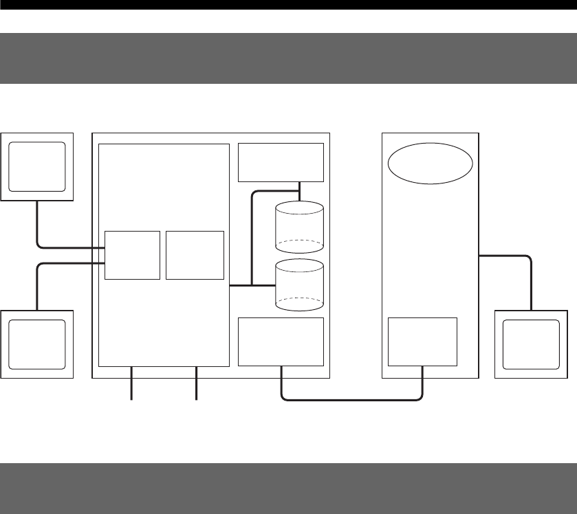
The following is a schematic drawing of the reference system.
This unit consists of the following parts:
•Cell-based system with peripherals such as Gigabit Ethernet and USB
•HDD and Blu-ray Disc drive
•Communication processor that controls communication with the development host PC
Coding and compiling should be performed on the host PC. The connection between the host PC and the
reference tool requires the use of an Ethernet connection.
The Communications Processor (CP) is hardware for debugging control that has its own flash memory,
Ethernet ports and network configuration, which are separate from those found in the PLAYSTATION®3
SDK, hardware and system software. The CP settings can be modified using the provided Web interface
which is accessible through the LAN connector for development.
Overview of the reference system
Unit features
Reference Tool Development Host Computer
LAN connection for developmentUSB
HDTV
monitor
RSXR
CPU
Cell
Broadband
EngineTM
Blu-ray Disc
Drive
Tool
Chain
HDD for
appl.
HDD for
BD emu.
PC
monitor
Communication
Processor
Ethernet
I/F
Gigabit
Ethernet
01GB01COV.book Page 8 Thursday, July 6, 2006 2:50 PM

G:\Sagyou\07 Jul\0706\837913S DECR-1000
A_GB\2886333111DEHR1000\01GB04PRE.fm
masterpage:Right
DECR-1000 A
2-886-333-11(1)
9
Equipment required to configure the reference system
Equipment required to configure the reference system
The following items are required to use the evaluation software package provided by SCE.
DECR-1000 A (this unit)
See “Part names and usage” (tpage 10).
Monitor
Either or both of the following can be used for graphics output from this unit:
•Standard PC monitor
Connected to the monitor connector of this unit
•TV monitor (supporting 480i, 480p, 1080i, 720p or 1080p)
Connected to the HDMI OUT connector or AV MULTI OUT connector of this unit
Development host PC
Coding, compiling, and debugging should be performed on a separate development host PC, which may
be a standard PC. When using a standard PC, it should be equipped with an Ethernet connector.
Refer to the “Reference Tool Software Setup Guide” document (supplied separately) for other
recommended functions and a description of performance levels.
Configuring the reference system requires the following:
•Installing the software package that comes with this unit on the development host PC.
Refer to the “Reference Tool Software Setup Guide” document (supplied separately).
•Setting up the reference tool.
Refer to “Preparing to use this unit” (tpage 16).
Equipment required to configure the reference
system
Reference system setup
01GB01COV.book Page 9 Thursday, July 6, 2006 2:50 PM
DECR-1000 A
2-886-333-11(1)
G:\Sagyou\07 Jul\0706\837913S DECR-1000
A_GB\2886333111DEHR1000\01GB04PRE.fm
masterpage:Left
10
Part names and usage
Part names and usage
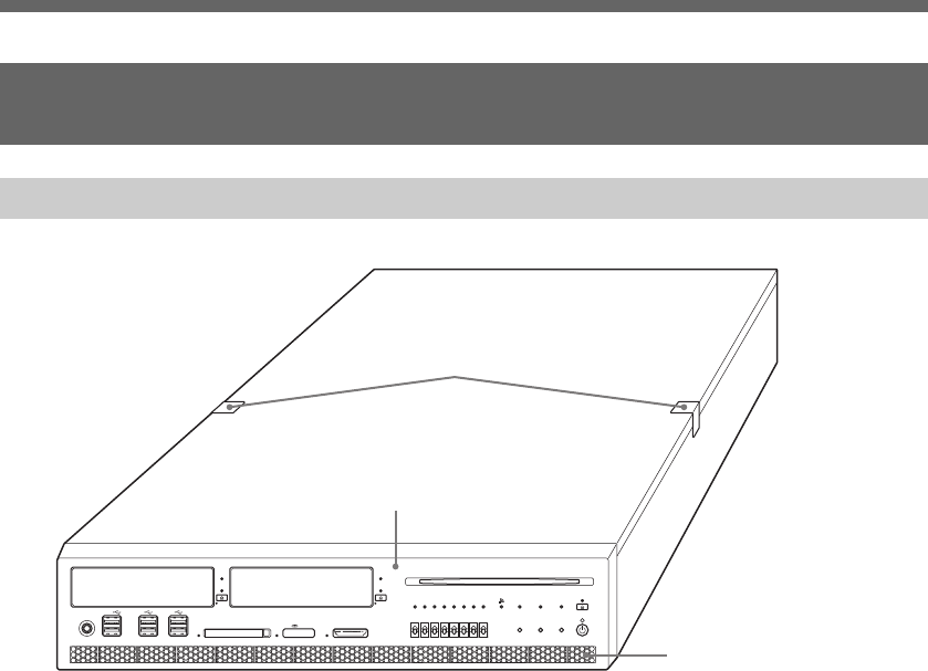
AFront panel
See “Front panel” (tpage 11) for details.
BVent
Be sure not to obstruct this vent, as doing so may cause a fire or a malfunction. Also, the unit
must be kept well away from a wall to satisfy this requirement.
CStickers
Never disassemble the unit.
Part names and usage
Unit front
1
3
2
01GB01COV.book Page 10 Thursday, July 6, 2006 2:50 PM
G:\Sagyou\07 Jul\0706\837913S DECR-1000
A_GB\2886333111DEHR1000\01GB04PRE.fm
masterpage:Right
DECR-1000 A
2-886-333-11(1)
11
Part names and usage
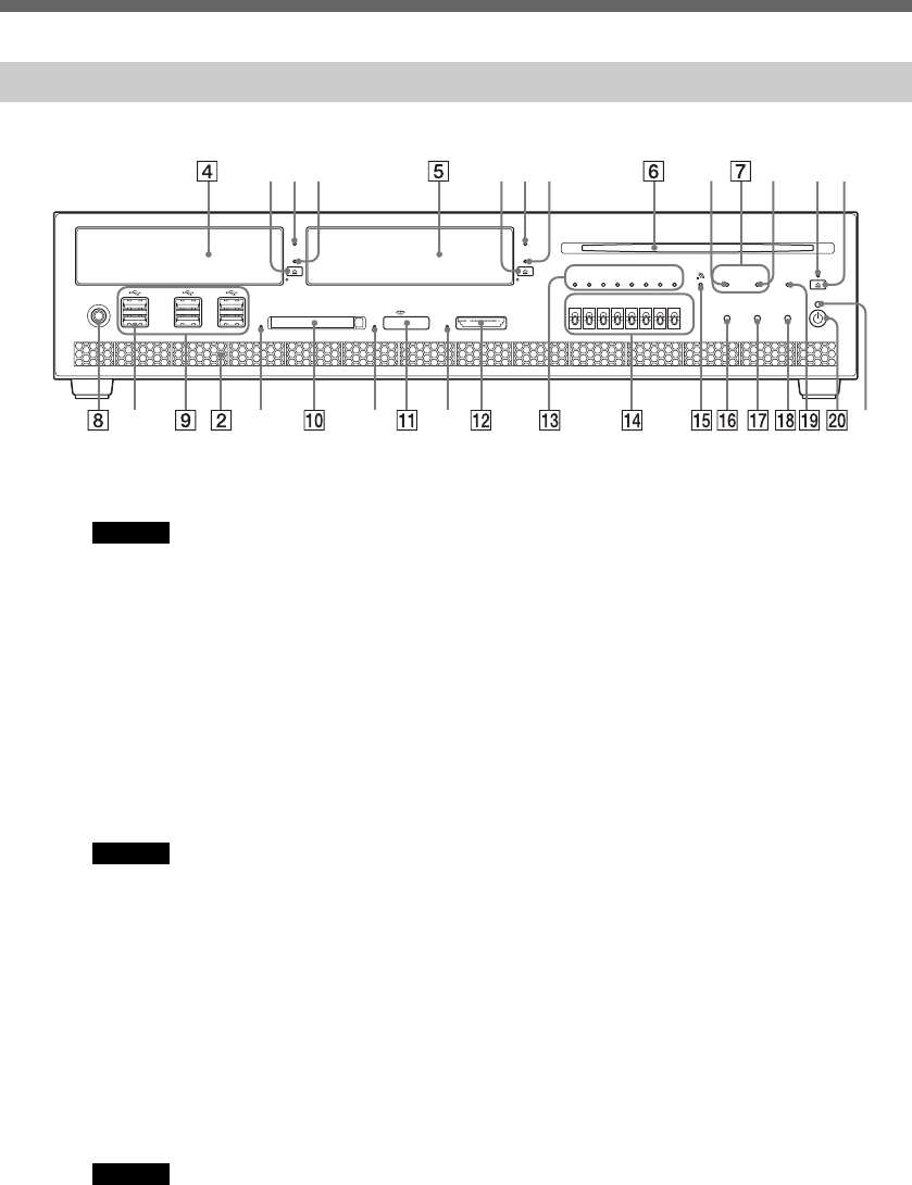
Part names and usage
DHDD bay
Corresponds to the HDD bay in the PLAYSTATION®3 console
Caution
If the HDD is removed improperly, it may result in data corruption or a malfunction. Before removing, check that the
HDD is not being accessed.
(4a) Eject button
(4b) HDD access indicator
Flashes while accessing the HDD
(4c) Eject indicator
Illuminates when the HDD is attached
EHDD(DEV) bay
This HDD is for use with the Blu-ray Disc drive emulation.
Caution
Cannot be used with the Blu-ray Disc drive simultaneously.
If the HDD is removed improperly, it may result in data corruption or a malfunction. Before removing, check that the
HDD is not being accessed.
(5a) Eject button
(5b) HDD(DEV) access indicator
Flashes while accessing the HDD(DEV)
(5c) Eject indicator
Illuminates when the HDD(DEV) is attached
FBlu-ray Disc drive
Caution
Cannot be used with the HDD(DEV) bay simultaneously. Also cannot be used with an 8 cm (3.15 in) disc adaptor.
When removing the disc, do not allow the recorded surface to become dirty or scratched.
(6a) Eject indicator
Illuminates when a disc is inserted
(6b) Eject button
Front panel
(9a) (10a) (11a) (12a) (20a)
(7a) (7b) (6a)(6b)(4a)(4b)(4c) (5a)(5b)(5c)
01GB01COV.book Page 11 Thursday, July 6, 2006 2:50 PM

DECR-1000 A
2-886-333-11(1)
G:\Sagyou\07 Jul\0706\837913S DECR-1000
A_GB\2886333111DEHR1000\01GB04PRE.fm
masterpage:Left
12
Part names and usage
Part names and usage
GDrive indicators
(7a) HDD(DEV) drive indicator
Illuminates when the HDD(DEV) bay is selected
(7b) BD drive indicator
Illuminates when the Blu-ray Disc drive is selected
HFoot switch connector
For connection to the supplied foot switch
IUSB connectors
For connecting a USB connector (A type)
(9a) Extension connectors
Currently not used
JCF slot
For inserting a CompactFlash® card
(10a) CF access indicator
Flashes while accessing a CompactFlash® card. While the slot is being accessed, do
not insert or remove the card. Doing so may result in damage to the card or data
corruption.
KMemory Stick™ slot
For inserting Memory Stick™ media
(11a) Memory Stick™ access indicator
Flashes while accessing Memory Stick™ media. While the slot is being accessed, do
not insert or remove the Memory Stick™ media. Doing so may result in damage to the
media or data corruption.
LSD Memory Card slot
For inserting an SD Memory Card
(12a) SD Memory Card access indicator
Flashes while accessing an SD Memory Card. While the slot is being accessed, do not
insert or remove the SD Memory Card. Doing so may result in damage to the card or
data corruption.
MGPO indicators
Can be controlled by the user program. Illumination status of these LEDs will change as the
boot sequence progresses.
NGPI switches
Can be used by the user program
OWLAN access indicator
Illuminates when a wireless LAN connection has been established and flashes while the
connection is being accessed
PReset button
For initiating a reset of the system
QNetwork initialise button
Restores the factory default values for the IP address settings. While holding down this button,
press the power button.
RSystem initialise button
Restores the factory default initial state to the communication processor software. While
holding down this button, press the power button.
01GB01COV.book Page 12 Thursday, July 6, 2006 2:50 PM

G:\Sagyou\07 Jul\0706\837913S DECR-1000
A_GB\2886333111DEHR1000\01GB04PRE.fm
masterpage:Right
DECR-1000 A
2-886-333-11(1)
13
Part names and usage
Part names and usage
SStatus indicator
The system status can be determined by the color and status of the status indicator.
TPower button
For turning on/off the power supply to the system. Pressing it continuously for more than 10
seconds will force the system to shut down.
(20a) Power indicator
The system status can be determined by the color and status of the power indicator.
Fast flashing red Indicates a system malfunction or that the unit’s internal
temperature may be too high. Either wait for a while and then
press the reset button, or turn the unit off once using the main
power switch and then turn it back on.
Slow flashing green Indicates startup of the communication processor, or that the
unit is updating, initializing or initializing the network
connection
Solid green Indicates the communication processor has finished startup
and is activating properly
Solid red System is powered off.
Solid green System is powered on.
Alternating red
and green
Indicates the unit’s internal temperature may be too
high. Turn the power button off, and then wait a while
before using again.
01GB01COV.book Page 13 Thursday, July 6, 2006 2:50 PM
DECR-1000 A
2-886-333-11(1)
G:\Sagyou\07 Jul\0706\837913S DECR-1000
A_GB\2886333111DEHR1000\01GB04PRE.fm
masterpage:Left
14
Part names and usage
Part names and usage
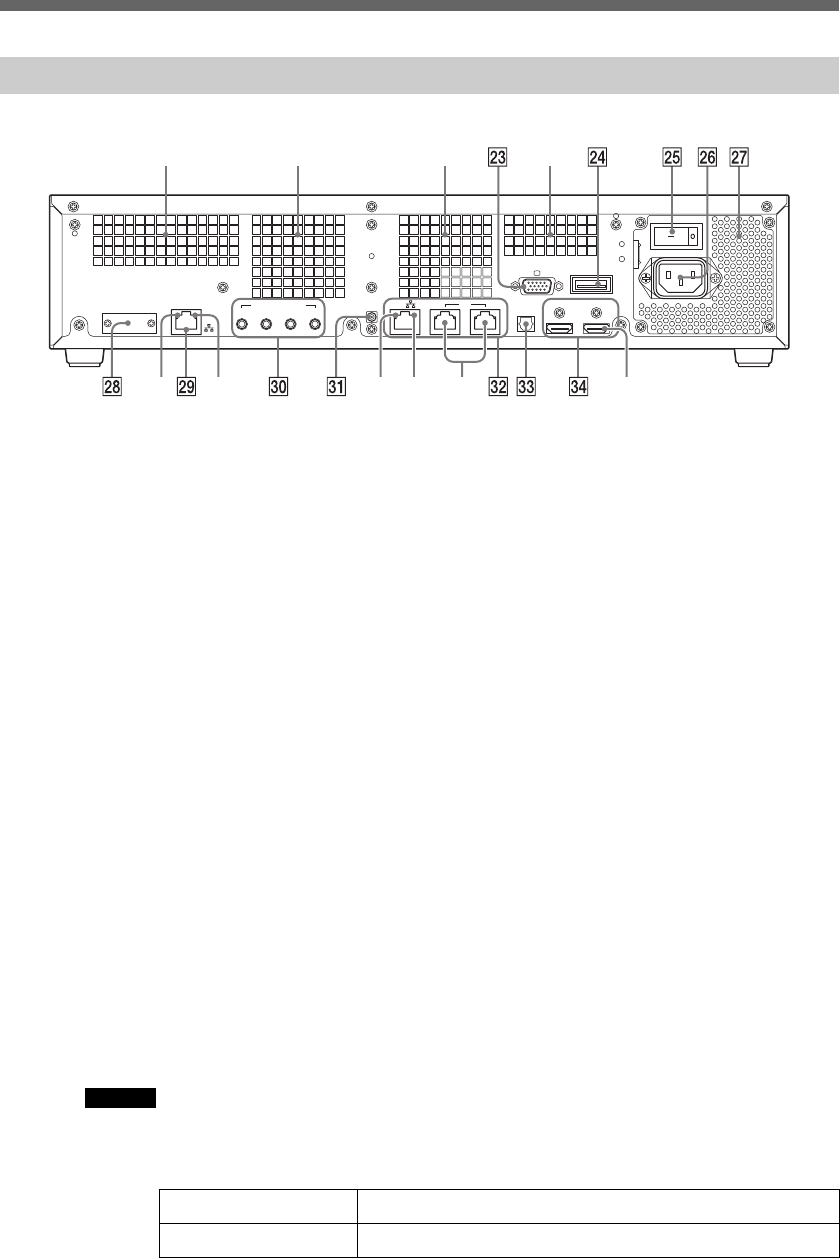
U(21a)(21b) Vent
Be sure not to obstruct these vents, as doing so may cause a fire or a malfunction. Also, the unit
must be kept at least 10 cm (3.94 in) away from a wall to satisfy this requirement.
V(22a)(22b) Vent fan
Be sure not to obstruct these vent fans, as doing so may cause a fire or a malfunction. Also, the
unit must be kept at least 10 cm (3.94 in) away from a wall to satisfy this requriement.
WMonitor connector
For connection to a device with a VGA input connector
XAV MULTI OUT connector
For connection to a device with an AV MULTI input connector
YMain power switch
ZAC IN connector
wj Vent
Be sure not to obstruct this vent, as doing so may cause a fire or a malfunction. Also, the unit
must be kept at least 10 cm (3.94 in) away from a wall or from the rear panel of the rack to
satisfy this requirement.
wk Service connector
For use by service personnel only
wl LAN connector for development
For connection to a debugging network through which the unit communicates with the
development host PC. Conforming to the auto-negotiation standard, it supports 10BASE-T,
100BASE-TX, and 1000BASE-T.
Its automatic polarity recognition feature allows the use of a straight cable instead of a cross
cable even when it is directly connected with the host PC. Use an Enhanced Category 5 or
Category 6 Ethernet cable to connect to a Gigabit hub or other Ethernet device.
The MAC address is displayed near the connector.
Caution
Be careful not to confuse this connector with the LAN connector for PLAYSTATION®3 es.
(29a) Link indicator
Unit rear
Off Transmission in 10-Mbps/100-Mbps mode
Solid green Transmission in 1000-Mbps mode
DIGITAL OUT
MONITOR AV MULTI OUT
MAIN POWER
~ AC IN
HDMI OUT
HDMI OUT(EXTRA)
(OPTICAL)
12
ANALOG AUDIO OUT EXT
DEV
LAN
LAN
34
ANT
(21a)
(29a) (29b)
(22a) (22b) (21b)
(34a)(32c)(32a)(32b)
01GB01COV.book Page 14 Thursday, July 6, 2006 2:50 PM
G:\Sagyou\07 Jul\0706\837913S DECR-1000
A_GB\2886333111DEHR1000\01GB04PRE.fm
masterpage:Right
DECR-1000 A
2-886-333-11(1)
15
Part names and usage
Part names and usage
(29b) Activity indicator
e; Analog audio out connector
For connection to a device with an ANALOG AUDIO input connector
ea Antenna connector
By connecting the supplied antenna, wireless LAN communication and Bluetooth function can
be used.
es LAN connectors for PLAYSTATION®3
Conforms to the auto-negotiation standard and supports 10BASE-T, 100BASE-TX, and
1000BASE-T.
For connection to an Ethernet device (e.g. Gigabit-hub) via an Enhanced Category 5 or
Category 6 Ethernet cable.
Caution
Be careful not to confuse this connector with the LAN connector for development wl.
(32a) Link indicator
(32b) Activity indicator
(32c) Extension connectors
Currently not used. Do not remove the sticker.
ed Digital out (optical) connector
For connection to a device with an optical digital input connector
ef HDMI OUT connectors
For connection to a device with an HDMI input conenctor
(34a) HDMI OUT (EXT) connector
Currently not used. Do not remove the sticker.
Solid yellow The Ethernet link is up but no traffic is present on it.
Flashing yellow Traffic is present on the link.
Off Transmission in 10-Mbps/100-Mbps mode
Solid green Transmission in 1000-Mbps mode
Solid yellow The Ethernet link is up but no traffic is present on it.
Flashing yellow Traffic is present on the link.
01GB01COV.book Page 15 Thursday, July 6, 2006 2:50 PM
G:\Sagyou\07 Jul\0706\837913S DECR-1000
A_GB\2886333111DEHR1000\01GB05GET.fm
masterpage:Chapter
Title_L
DECR-1000 A
2-886-333-11(1)
16 Attaching the vertical stand
Chapter 2
Preparing to use this unit
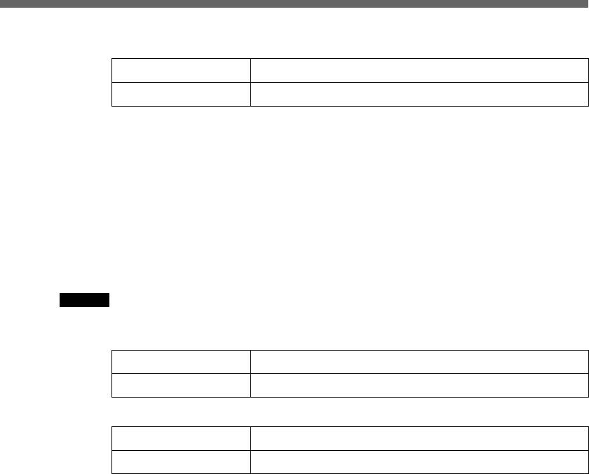
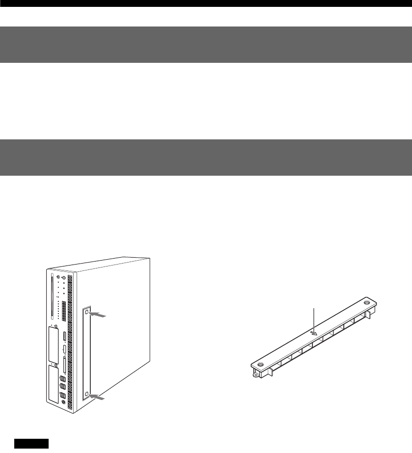
Attach the supplied vertical stand to the unit when using it in a vertical position.
Position the unit so that the mounting holes on the unit's left side align with those on the flat surface of the
stand. Use the supplied mounting screws to attach the stand.
Caution
• This operation should be done by two or more persons.
• Always attach the stand to the left side of the unit.
• If the mounting holes on the unit's left side do not align with those on the stand, try turning the stand around so that they line up
correctly.
Attaching the vertical stand
01GB01COV.book Page 16 Thursday, July 6, 2006 2:50 PM
G:\Sagyou\07 Jul\0706\837913S DECR-1000
A_GB\2886333111DEHR1000\01GB05GET.fm
masterpage:Right
DECR-1000 A
2-886-333-11(1)
17
Attaching the unit to the rack
Attaching the unit to the rack
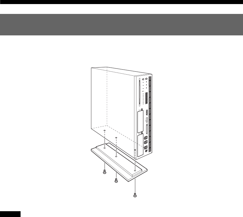
Using the supplied rack mount kit, you can attach the unit to an EIA Standard 19-inch rack.
Type A
Type B (server rack)
Attaching the unit to the rack
Applicable rack
700 mm (27.56 in) or more
Rack width
580 - 710 mm
478 mm
469 mm
452 mm
465 mm
700 mm (27.56 in) or more
Rack width
640 - 810 mm
452 mm
465 mm
01GB01COV.book Page 17 Thursday, July 6, 2006 2:50 PM
DECR-1000 A
2-886-333-11(1)
G:\Sagyou\07 Jul\0706\837913S DECR-1000
A_GB\2886333111DEHR1000\01GB05GET.fm
masterpage:Left
18
Attaching the unit to the rack
Attaching the unit to the rack
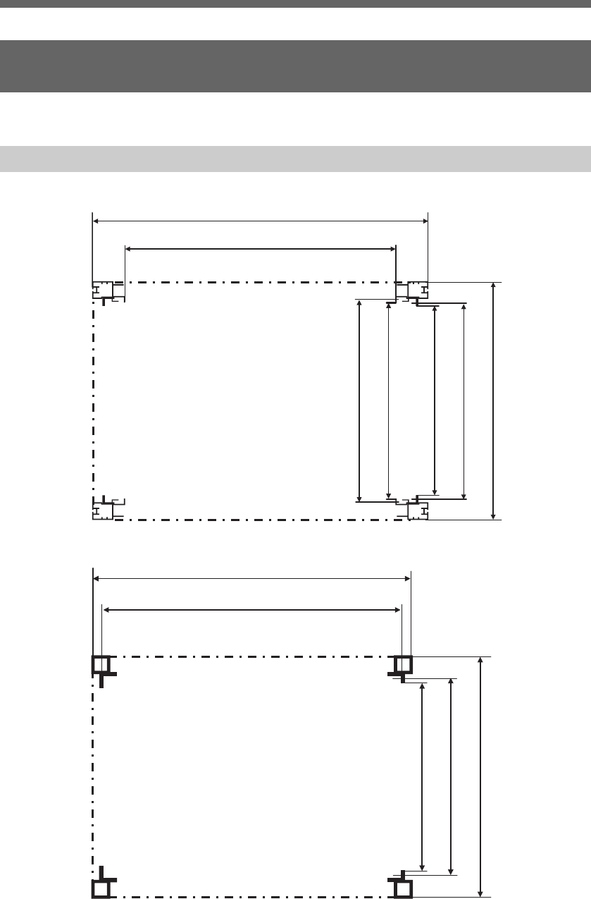
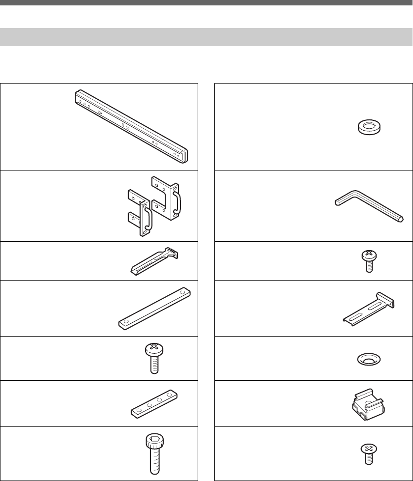
The rack mount kit contains the following components. Before you assemble the rack mount, make sure
that you have all the components. Depending on the rack type, some components may not be necessary.
List of components
ARail × 2 HFlat washer × 8
BHandle × 2 IL-shaped hexagonal
wrench × 1
CRail bracket (type A)
× 4
JScrew (B5 × 14) × 4
DPlate nut (large) × 4 KRail bracket (type B)
× 4
EScrew (B4 ×8) × 22 LSpacer × 8
FPlate nut (small) × 4 MCage nut × 8
GHexagon socket head
cap screw × 8
NScrew (K4 × 10) × 8
01GB01COV.book Page 18 Thursday, July 6, 2006 2:50 PM
G:\Sagyou\07 Jul\0706\837913S DECR-1000
A_GB\2886333111DEHR1000\01GB05GET.fm
masterpage:Right
DECR-1000 A
2-886-333-11(1)
19
Attaching the unit to the rack
Attaching the unit to the rack
Caution
• The unit should be installed into the rack mount by two or more persons. The unit must be firmly supported when it is placed onto
the rails. If not, an injury or accident could result. Take care not to catch your fingers between a stopper and a rail.
• Pay attention to elevations in the unit’s internal temperature. For information on operating conditions, see “Specifications”
(tpage 34).
• Position the unit so that there is at least 10 cm (3.94 in) of space behind the vents on the unit rear to prevent anything from blocking
the vents. Arrange the cables so that they do not block the vents. Also, if using a rack that has a front cover, check that the flow of
air into the unit’s vents is not blocked.
• Regularly clean the filter unit (tpage 31).
• When installing the rack or unit, secure all necessary parts and components and perform work under stable conditions.
• Connect the supplied AC power cord to power sources that use the appropriate capacity and protective circuitry. For information
on power capacity, refer to the label on the unit.
• Connect all AC power cords used by the devices within the rack to power strip(s).
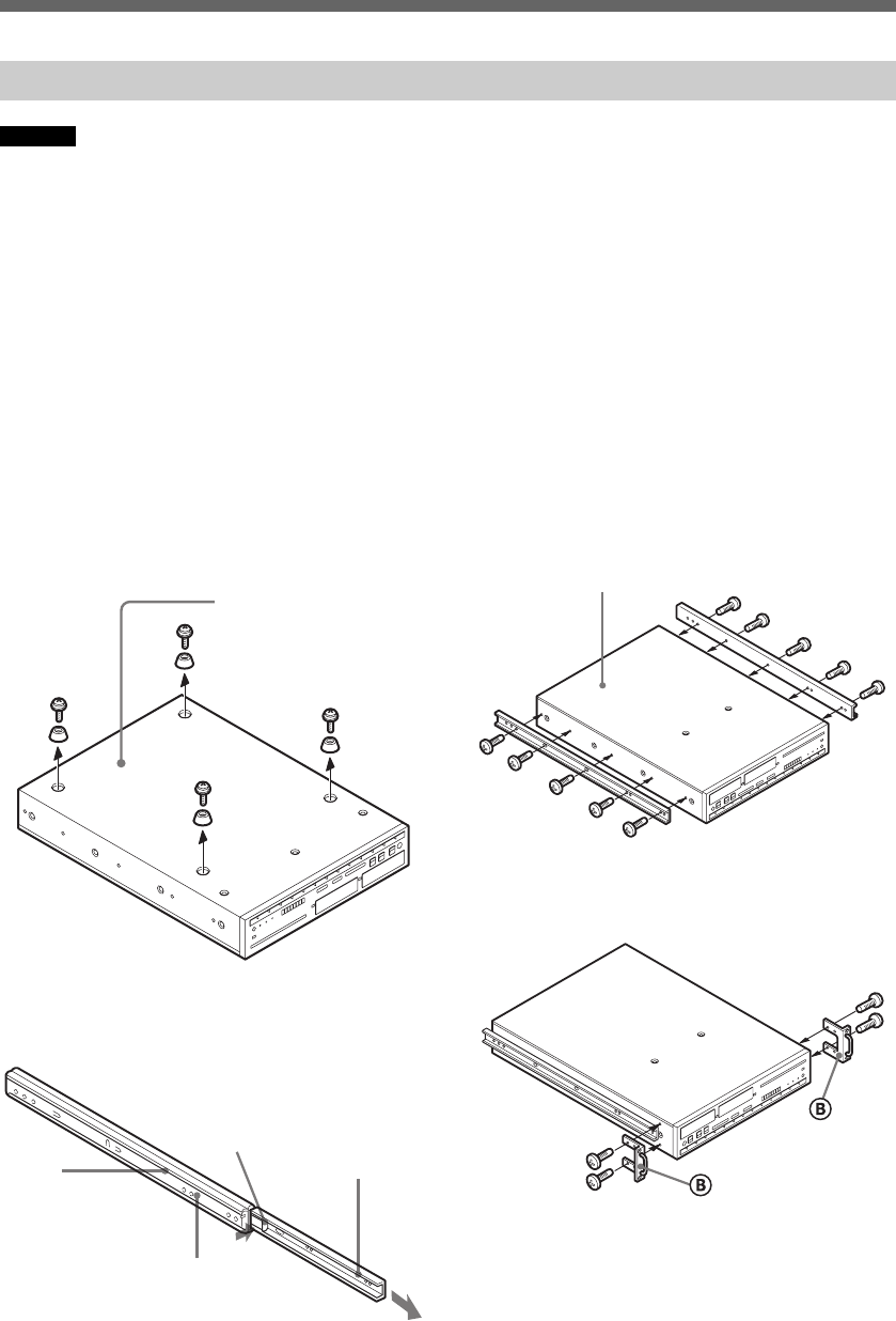
1 Attaching the inner rails to the unit
1Remove the feet and screws from the
bottom of the unit.
Retain them for possible future use.
2While pressing down the stopper, pull
out the inner rail from the rail A.
3Attach the inner rails to both sides of the
unit using the screws E.
4Attach the handles B to both sides of
the unit using the screws E.
Installation
Bottom side
A
Outer
rail
Inner rail
Stopper
Top side
01GB01COV.book Page 19 Thursday, July 6, 2006 2:50 PM
DECR-1000 A
2-886-333-11(1)
G:\Sagyou\07 Jul\0706\837913S DECR-1000
A_GB\2886333111DEHR1000\01GB05GET.fm
masterpage:Left
20
Attaching the unit to the rack
Attaching the unit to the rack
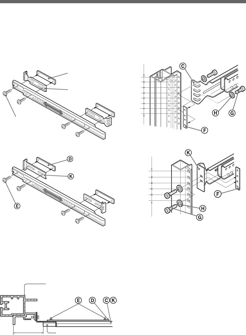
2 Attaching the outer rails to the rack
1Attach the rail brackets (type A) C or
(type B) K to the outer rails with the
large plate nuts D and screws E, but
do not tighten the screws at this point.
2Adjust the bracket position so that the
end of each rail is at least 60 mm (at least
2.36 in) away from where the handles are
to be attached to the rack, and then
tighten the screws E to secure the rail
brackets.
3Attach the brackets to the rack using the
small plate nuts F, hexagon socket head
cap screws G, and flat washers H.
E
C
D
Rack (type A)
Rack (type B)
Rack
Outer rail
60 mm
(2.36 in) or more
12.7
15.9
15.9
12.7
15.9
15.9
12.7
(mm)
15.9
15.9
12.7
15.9
15.9
(mm)
Rack (type B)
Rack (type A)
01GB01COV.book Page 20 Thursday, July 6, 2006 2:50 PM
G:\Sagyou\07 Jul\0706\837913S DECR-1000
A_GB\2886333111DEHR1000\01GB05GET.fm
masterpage:Right
DECR-1000 A
2-886-333-11(1)
21
Attaching the unit to the rack
Attaching the unit to the rack
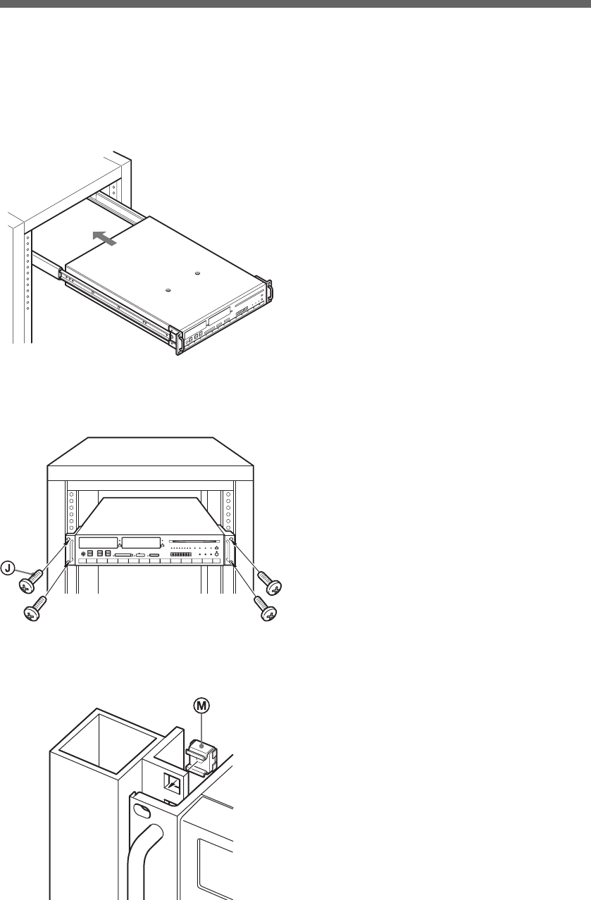
3 Mounting the unit into the rack
1While pressing the stoppers, insert the
inner rails into the outer rails. Then,
slide the unit onto the rack and push it
as far into the rack as possible.
2Use the screws J on the upper or lower
screw holes of the handles to secure
them to the rack.
When using the rack (type B), attach the cage
nut M to the metal plate on the rack prior to
installation.
01GB01COV.book Page 21 Thursday, July 6, 2006 2:50 PM
DECR-1000 A
2-886-333-11(1)
G:\Sagyou\07 Jul\0706\837913S DECR-1000
A_GB\2886333111DEHR1000\01GB05GET.fm
masterpage:Left
22
When using Ethernet cables
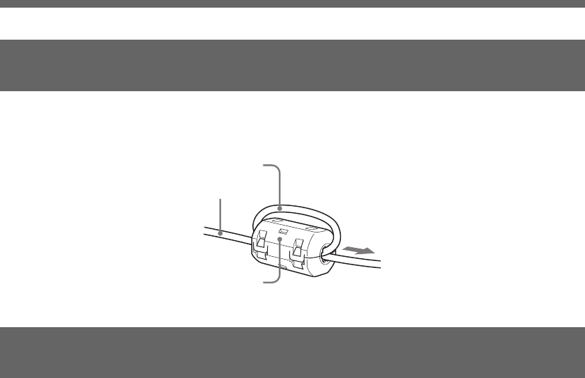
When using Ethernet cables
Install the supplied RFI filter on the Ethernet cable (shielded twisted pair cable). Install the RFI filter
10cm (3.94 in) away from the main unit.
When installing the RFI filter on the cable, wind the cable once around the RFI filter, as shown below.
1Connect the power cables.
Check that the main power switch (tpage 14) is off. Before connecting the power cord, attach the
supplied AC power cord clamp to the unit end of the power cord. Then, connect the AC power cord
connector to the AC IN connector (tpage 14).
Insert until the clamp locks in position. When disconnecting, hold the tabs of the clamp and pull.
2Connect the monitor.
If using an HDTV monitor, connect an HDMI cable to the HDMI OUT connector (tpage 15).
Optionally, connect an AV MULTI cable to the AV MULTI OUT connector (tpage 14).
3Connect this unit and the development host PC to the debugging network.
For details, see “Connections for a debugging network” (tpage 23).
4Make other interface connections.
Make connections to the Gigabit Ethernet and/or USB device as necessary.
Connect an Enhanced Category 5 or Category 6 Ethernet cable between the LAN connector for
P L AYS TATI O N ® 3 (tpage 15) and the network device (e.g. Gigabit-Ethernet hub), and then connect
the cables of USB devices to the USB connectors (tpage 12).
(For supported USB devices, refer to the documents on USB-related libraries.)
When using Ethernet cables
Connecting the hardware
cable
Install near the unit
cable
RFI filter
01GB01COV.book Page 22 Thursday, July 6, 2006 2:50 PM

G:\Sagyou\07 Jul\0706\837913S DECR-1000
A_GB\2886333111DEHR1000\01GB05GET.fm
masterpage:Right
DECR-1000 A
2-886-333-11(1)
23
Connections for a debugging network
Connections for a debugging network
The following items are necessary in order to set
up the debugging network for this unit:
Caution
Under the factory default settings, an analog RGB- or PAL-
compatible display will not display the initial settings for the
debugging network.
The following information is required to set up the
unit.
For information on the configuration of the
network you will be connecting the unit to, contact
the network administrator.
If there is no DHCP server on the network
Create a local area network using the unit and the
development PC. Under this network, the
following static IP address will be assigned to the
unit automatically.
IP address: 192.168.0.2
Subnet mask: 255.255.255.0
Caution
• The IP address and subnet mask settings are factory default
values. If the unit’s network settings change, these settings
will also change accordingly.
• If connecting to a network with settings that are different
from the above, first use a local area network to confirm the
connection following the procedures contained in this
section, and then proceed with adjusting the unit’s network
settings. For information on the unit's network settings, see
“Setting up with the administration tool” (tpage 25). After
adjusting the network settings for the unit and the
development PC, connect the two components to an existing
Ethernet hub on the network.
If there is a DHCP server on the network
Connect the unit and the development PC with the
DHCP client software to an Ethernet hub on the
network. In this case, setting such as the IP address
and subnet mask will be obtained automatically
once the power is on. Depending on the DHCP
server’s settings, settings such as those for the
DNS server or default gateway may also be set
automatically. To determine which settings are
obtained automatically, contact the network
administrator.
1Connect the unit to the hub with the
Ethernet cable.
2Connect the hub to the host PC with the
Ethernet cable.
Set up the development PC before setting up the
unit.
If there is no DHCP server on the network
1Turn on the development PC.
2Set up the network for the development
PC.
Set the following information.
IP address: 192.168.0.1
Subnet mask: 255.255.255.0
If there is a DHCP server on the network
1Turn on the development PC.
Connections for a debugging network
Items required for connection
•Reference tool (this unit)
•Ethernet cables × 2
•Ethernet hub
•AV MULTI 480i- or HDMI 480p-compatible
display
•Host PC
Information required for setup
•Availability of a DHCP server
•IP address
•Subnet mask
•IP address for the default gateway
Connection setup
Making connections
Setting up the development PC
01GB01COV.book Page 23 Thursday, July 6, 2006 2:50 PM

DECR-1000 A
2-886-333-11(1)
G:\Sagyou\07 Jul\0706\837913S DECR-1000
A_GB\2886333111DEHR1000\01GB05GET.fm
masterpage:Left
24
Connections for a debugging network
Connections for a debugging network
2Create settings for the development PC.
Start the DHCP client software and set up the
development PC in advance to obtain the IP
address and other settings from the DHCP
server. For information on operating the
software and obtaining the IP address, refer to
the instruction manual for the development PC.
3Create settings for the DHCP server.
When obtaining the IP address from the DHCP
server, the assigned IP address usually differs
each time. Using a static IP address will
facilitate operating the unit. To set a static IP
address, contact the network administrator.
After connecting the host PC and the AV MULTI
480i- or HDMI 480p-compatible display, turn on
the reference tool and the system.
1Turn on the main power switch
(tpage 14).
This turns on the unit and starts system
initialization. During initialization, the status
indicator flashes green. This indicator stops
flashing when the initialization process is
complete.
Caution
Do not operate the unit during initialization.
2Press the power button.
The power indicator will change from red to
green. After approximately 30 seconds, the
system will start up.
Caution
Do not operate while the system is starting up.
3Confirm the information that is displayed.
Check that the following information is
displayed:
Settings information appears on the display in
the following cases:
Caution
• To restore the system of the communication processor to
the factory default settings, while holding down the
system initialise button, press the power button.
• Under the factory default settings, the AV MULTI 480i-
or HDMI 480p setting is used. To restore the factory
default settings after video settings have been adjusted,
press and hold the power button for more than 5 seconds
to start the system.
• To restore the IP address to the factory default setting,
while holding down the network initialise button, press
the power button.
For details on adjusting network settings, see
“Setting up with the administration tool” >
“Network” (tpage 30).
Confirming the settings information
•IP address
•Subnet mask
•Broadcast address
•IP address for the default gateway
•MAC address
•Host name
•When the main power switch is on
•When network information is changed by the
administration tool
•When the IP address has been restored to the
factory default setting
•When the system of the communication
processor has been restored to the factory
default settings
•When the administration tool’s “Restart of
dtnem” command has been executed
Adjusting network settings
01GB01COV.book Page 24 Thursday, July 6, 2006 2:50 PM
G:\Sagyou\07 Jul\0706\837913S DECR-1000
A_GB\2886333111DEHR1000\01GB05GET.fm
masterpage:Right
DECR-1000 A
2-886-333-11(1)
25
Setting up with the administration tool
Setting up with the administration tool
Connect the host PC to the network of the unit.
Then set up a web browser disabling the use of
proxy servers. Refer to the instruction manual of
the host PC for more details.
After configuring the debugging network settings
of the host PC, turn on the unit.
1Turn on the main power switch
(tpage 14).
This turns on the unit and starts system
initialization. During initialization, the power
indicator flashes red. This LED turns solid red
when the initialization process is complete.
Start up the administration tool on the host PC.
The following section assumes use of the IP
address 192.168.0.2 for the unit.
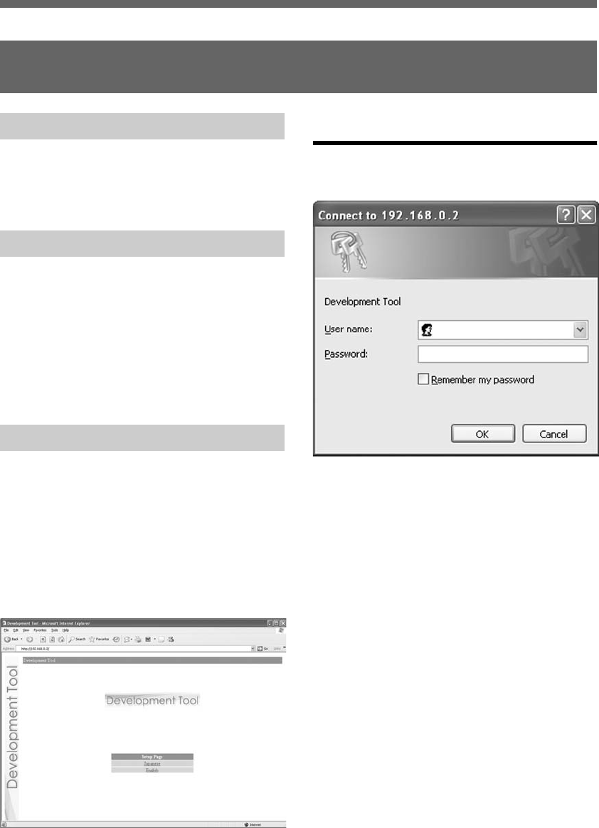
1Start the Web browser on the host PC.
2Type http://192.168.0.2/ in the address
field of the Web browser, and press the
Enter key.
The language selection screen is displayed.
3Select the display language for the
administration tool.
The login screen is displayed.
Select the language (for example English) here.
Login
Log in with a user name and password.
1Enter the user name and password as
follows:
To log in as the administrator, enter the
“Administrator” user name and password as
follows:
When logged in as the administrator, all of the
functions shown in the Administration Tools menu
are active.
To log in as a user, enter the user name and
password as follows:
When logged in as a user, only the “User”
functions shown in the Administration Tools menu
are active. The “Administrator” functions cannot
be used.
Setting up with the administration tool
Preparing for setup
Turning on the unit
Starting the administration tool
•user name: Administrator
•password: Administrator
* These are the factory default settings.
•user name: User
•password: User
* These are the factory default settings.
01GB01COV.book Page 25 Thursday, July 6, 2006 2:50 PM
DECR-1000 A
2-886-333-11(1)
G:\Sagyou\07 Jul\0706\837913S DECR-1000
A_GB\2886333111DEHR1000\01GB05GET.fm
masterpage:Left
26
Setting up with the administration tool
Setting up with the administration tool
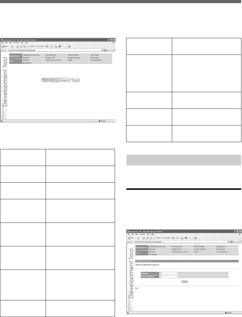
2Click “OK”.
Upon successfully logging in, the main screen of
the administration tool is displayed.
Administrator
These options allow the user to modify settings
and update the software of the unit.
User
The following unit settings can be displayed.
Some settings can also be adjusted.
Click on the desired item to the right of
“Administrator”.
Administrator password
Upon clicking “Administrator password”, the
following screen is displayed. This screen is
utilized to change the password used for
administrator authentication.
Enter the desired password in the “Password” and
“Retype Password” fields. Click “Setting” to
complete the configuration.
Administrator
password
Change the administrator
password.
User password Change the user
password.
Reset of setting Initialize the selected
settings.
Save & load Save settings, and
synchronize the saved
settings with this unit.
Network Configure the necessary
settings for network
connections.
Update of CP Update the software for
the communication
processor.
Restart of
dtnetm
Restart programs
communicating with the
host PC via the DECI
protocol.
Date & time Configure the time and
time zone.
Network Verify the network
settings.
Software
version of CP
Verify the version
numbers of software
packages for the installed
communication
processor.
Target Check the status of the
development target.
Boot
parameters
Verify and change the
boot parameters settings.
BD emulator Confirm or change the
BD emulator settings.
Setting up – Administrator
01GB01COV.book Page 26 Thursday, July 6, 2006 2:50 PM
G:\Sagyou\07 Jul\0706\837913S DECR-1000
A_GB\2886333111DEHR1000\01GB05GET.fm
masterpage:Right
DECR-1000 A
2-886-333-11(1)
27
Setting up with the administration tool
Setting up with the administration tool
Caution
• For security purposes, be sure to change the default password.
• The password must be a combination of both letters and
numeric characters. Passwords consisting of all lowercase, all
uppercase or all numeric characters are not allowed.
• A password may be seven or eight characters long. Passwords
fewer than seven characters long are not allowed. Also, if nine
or more characters are entered, only the first eight characters
are set as the password.
• If an error is made in entering the password, or the values
entered into the “Password” and “Retype password” fields do
not match, an error message is displayed. If this occurs, enter
the password again.
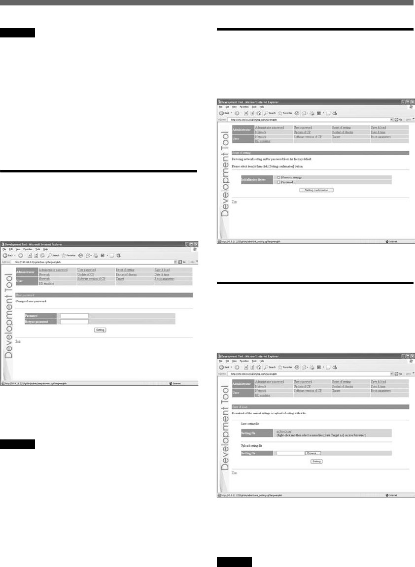
User password
Upon clicking “User password”, the following
screen is displayed. This screen is utilized to
change the user password used to log in to the
system.
Enter the desired password in the “Password” and
“Retype Password” fields. Click “Setting” to
complete the configuration.
Caution
• For security purposes, be sure to change the default password.
• The password must be a combination of both letters and
numeric characters. Passwords consisting of all lowercase, all
uppercase or all numeric characters are not allowed.
• A password may be seven or eight characters long. Passwords
fewer than seven characters long are not allowed. Also, if nine
or more characters are entered, only the first eight characters
are set as the password.
• If an error is made in entering the password, or the values
entered into the “Password” and “Retype password” fields do
not match, an error message is displayed. If this occurs, enter
the password again.
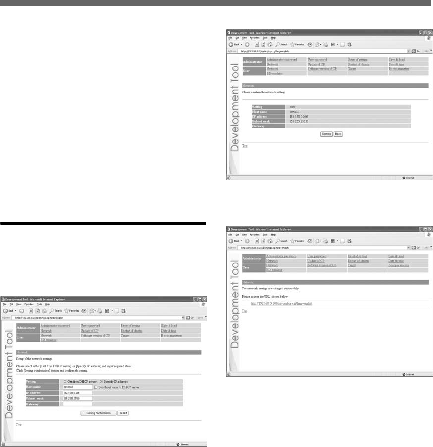
Reset of setting
Upon clicking “Reset of setting”, the following
screen is displayed. This screen is used to restore
the factory default Network & Access control
settings and/or administrator password.
Select the items to be initialized and click “Setting
confirmation” to complete initialization.
Save & load
Upon clicking “Save & load”, the following screen
is displayed. This screen is used to save the current
settings of the unit or to upload settings saved as a
file on the host PC to the unit.
To save the current setting of the unit on
the host PC:
Right-click on “ps3tool.conf” and then select
“Save Target As” or “Save Link As”.
Caution
This procedure may vary depending on the web browser used.
For details, refer to the instructions for the web browser.
01GB01COV.book Page 27 Thursday, July 6, 2006 2:50 PM
DECR-1000 A
2-886-333-11(1)
G:\Sagyou\07 Jul\0706\837913S DECR-1000
A_GB\2886333111DEHR1000\01GB05GET.fm
masterpage:Left
28
Setting up with the administration tool
Setting up with the administration tool
To configure the unit using settings
saved on the host PC:
1Check that the IP address defined in the
host PC’s settings file is the same as
that assigned to the unit.
If the IP address defined in the settings file and
the unit’s IP address are different, use a text
editor to change the IP address in the settings
file on the host PC to that assigned to the unit.
2Click “Browse” and select the setting file.
3Click “Setting”.
This causes the settings of the unit to be
updated.
Network
Upon clicking “Network”, the following screen is
displayed. This screen is used to change the
method for obtaining an IP address and to change
the values required for network configuration.
If you want to change the network settings, enter
the new network settings in the appropriate fields
in this screen and then click “Setting
confirmation”. The following confirmation screen
is then displayed.
Click “Setting” to begin processing the settings.
After the configuration is set, the following screen
is displayed.
Modify the network connection mode as needed,
and access the URL displayed on the screen.
01GB01COV.book Page 28 Thursday, July 6, 2006 2:50 PM
G:\Sagyou\07 Jul\0706\837913S DECR-1000
A_GB\2886333111DEHR1000\01GB05GET.fm
masterpage:Right
DECR-1000 A
2-886-333-11(1)
29
Setting up with the administration tool
Setting up with the administration tool
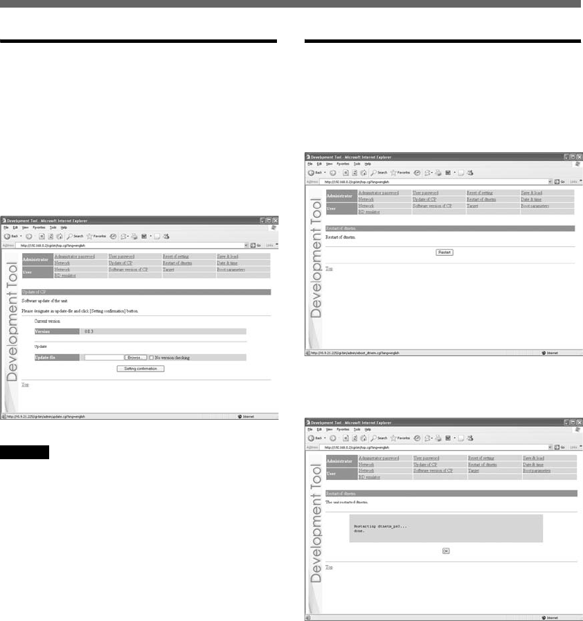
Update of CP
Upon clicking “Update of CP”, the following
screen is displayed. This screen is used to update
the software required by the communication
processors.
1Place the file for updating in the
appropriate directory on the host PC,
and click “Update of CP”.
The following screen appears.
Caution
Upon clicking “Setting confirmation” (see the step below),
the version of the file that is already installed and that of the
update file are checked to confirm whether the update file is
more recent and to confirm the dependency relationships
between them.
This check is not performed if “No version checking” is
selected. It is recommended that the default setting (“Check
versions”) be used.
2Enter the path to the file, and click
“Setting confirmation”.
The following screen is displayed, and the
contents of the update file are displayed.
3Verify the contents of the file, and click
“Setting”.
The installation will begin.
If the contents are incorrect, click “Back” to
make corrections.
Restart of dtnetm
“dtnetm” is a program used to communicate
between the unit and development host PC via the
DECI protocol.
Upon clicking “Restart of dtnetm”, the following
screen is displayed.
Click “Restart” to restart dtnetm and display the
restart status. After completing the restart, the
following screen is displayed.
01GB01COV.book Page 29 Thursday, July 6, 2006 2:50 PM
DECR-1000 A
2-886-333-11(1)
G:\Sagyou\07 Jul\0706\837913S DECR-1000
A_GB\2886333111DEHR1000\01GB05GET.fm
masterpage:Left
30
Setting up with the administration tool
Setting up with the administration tool
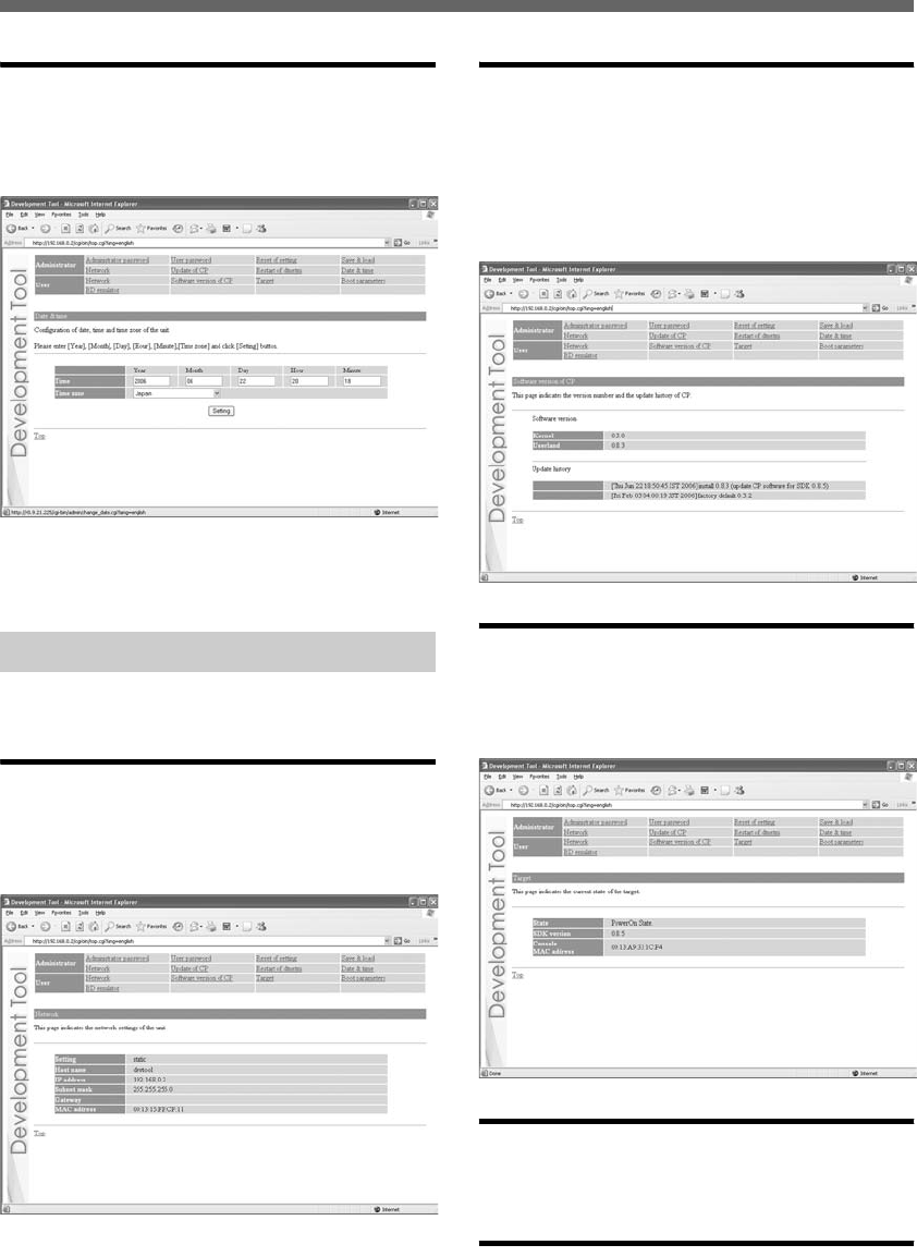
Date & time
Upon clicking “Date & time”, the following screen
is displayed. This screen is used to configure the
date, time and time zone.
Enter values for the year, month, day and time, and
select the time zone. Click “Setting” to complete
the configuration.
Click items to the right of “User” to adjust various
settings.
Network
Upon clicking “Network”, the following screen is
displayed. This screen allows the user to verify the
unit’s network settings.
Software version of CP
Upon clicking “Software version of CP”, the
following screen is displayed. This screen displays
the versions of the software packages for the
communication processor in stalled on the unit and
allows the user to verify the update history of the
unit.
Target
Upon clicking “Target”, the following screen is
displayed. This screen allows the user to verify the
status of the target.
Boot parameters
Verify and change the boot parameters settings.
For details, refer to the SDK documentation.
BD emulator
Verify and change BD emulator settings. For
details, refer to the SDK documentation.
Adjusting various settings – User
01GB01COV.book Page 30 Thursday, July 6, 2006 2:50 PM
G:\Sagyou\07 Jul\0706\837913S DECR-1000
A_GB\2886333111DEHR1000\01GB06SPC.fm
masterpage:Chapter
Title_R
DECR-1000 A
2-886-333-11(1)
31Handling the unit
Chapter 3
Appendices
•To avoid malfunction, check that the AC power cord is correctly and securely connected. Turn off the
main power switch on the unit rear when not in use.
•Do not put heavy or flammable objects on the unit, as doing so may warp the top panel.
If dust accumulates around the filter unit on the unit bottom, it may lead to malfunction. Regularly clean
the filter unit.
1Remove the filter unit from the main
unit.
Remove the screws from the unit bottom.
Caution
When the main unit is in a horizontal position, always have
two or more persons operate when removing or reinserting
the filter unit. If the main unit falls, it could lead to injury
or malfunction.
2Clean the filter unit with a vacuum
cleaner or similar product.
3Reinsert the filter unit.
Use the screws to reattach it to the main unit.
Attach so that the arrow on the filter unit is
pointing to the main unit’s rear side.
Handling the unit
Cleaning the filter unit
arrow
01GB01COV.book Page 31 Thursday, July 6, 2006 2:50 PM

DECR-1000 A
2-886-333-11(1)
G:\Sagyou\07 Jul\0706\837913S DECR-1000
A_GB\2886333111DEHR1000\01GB06SPC.fm
masterpage:Left
32 Troubleshooting
Troubleshooting
The power does not turn on.
tCheck that the AC power cord is securely connected and the main power switch (tpage 14) is
turned on.
The unit cannot be accessed over the network while in use.
tCheck that the power indicator illuminates.
tCheck that the Ethernet cable is securely connected.
tCheck that the unit’s settings have not been changed by other PCs. Contact your network
administrator for assistance.
When network settings are modified, the unit can no longer be accessed.
tThe network setting may not be correct.
Check that you can access the currently connected network using the values for IP address/subnet
mask that have been configured. For details, please consult your network administrator.
To check whether the host PC and the unit are correctly communicating, start the ping command
from the host PC. For details regarding the use of the ping command, see the “About the ping
command” section below, or refer to the instruction manual supplied with the host PC.
While holding down the network initialise button, press the power button to restore the factory
default values for the IP address settings.
About the ping command
If your host PC’s operating system supports the “ping” command, enter the ping command as
shown below.
# ping (the IP address of the unit)
When network communications are functioning, you will see information like the following at a
fixed interval.
PING 192.168.0.2(192.168.0.2):56(84)data bytes
64 bytes from 192.168.0.2:icmp_seq=0
ttl=64 time=0.1ms
64 bytes from 192.168.0.2:icmp_seq=1
ttl=64 time=0.1ms
64 bytes from 192.168.0.2:icmp_seq=2
When network communications are not functioning, the information will stop after the following:
PING 192.168.0.2(192.168.0.2):56 data bytes
Troubleshooting
01GB01COV.book Page 32 Thursday, July 6, 2006 2:50 PM

G:\Sagyou\07 Jul\0706\837913S DECR-1000
A_GB\2886333111DEHR1000\01GB06SPC.fm
masterpage:Right
DECR-1000 A
2-886-333-11(1)
33Troubleshooting
Troubleshooting
If the display appears as shown above, check the following:
• Is the Ethernet cable securely connected to the LAN connector for development on the unit?
• Is the Ethernet cable securely connected to the hub?
• Is the Ethernet cable securely connected to the host PC?
• Do the network settings of the host PC match those of the unit?
After checking the above items, start the ping command from the host PC. Then check the
indicators located near the LAN connector for development on the unit rear.
The unit cannot be accessed, even though five minutes have elapsed since it was
turned on.
tCheck that the power indicator lights up in green.
If so,
There may be a problem with the Ethernet cable or the connected hub. Change the Ethernet cable or
hub, or contact your network administrator for assistance.
Status indicator is flashing red.
tIf the status indicator (tpage 13) is flashing red, there may be a system malfunction or the
unit’s internal temperature may be too high. Wait a while and then press the reset button or turn
off the unit once using the main power switch, and then turn the unit back on.
If the status indicator flashes frequently, it may be an indication of a malfunction in the unit. In this
case, contact your sales representative.
The unit does not function properly when using storage media.
tFor information on problems related to Memory Stick™ media, CompactFlash® or SD Memory
Card use, contact the manufacturer from where you obtained the media.
01GB01COV.book Page 33 Thursday, July 6, 2006 2:50 PM

DECR-1000 A
2-886-333-11(1)
G:\Sagyou\07 Jul\0706\837913S DECR-1000
A_GB\2886333111DEHR1000\01GB06SPC.fm
masterpage:Left
34 Specifications
Specifications
Power
Input voltage AC 100-240V
Input current 9-4A
Rated frequency 50/60 Hz
Operating environment
Operating temperature 5 - 35°C (41 - 95°F)
Operating humidity 30% - 80% (with no condensation)
Dimensions (excluding protrusions)
424 × 88 × 596 mm (16.69 × 3.46 × 23.46 in)
(w/h/d)
Mass
Approx. 18 kg (39.68 lb)
Cell processor (CBE)
Clock frequency 3.2 GHz
Main memory
512 MB
Built-in peripherals
Communication processor (300 MHz)
External interfaces
Blu-ray Disc drive ×1
HDD ×2
USB connector ×4
Extension connector ×2 (currently not used)
Memory Stick™ slot ×1
CF slot ×1
SD Memory Card slot ×1
Foot switch connector ×1
Antenna connector ×1
Wireless LAN IEEE 802.11b/g
Bluetooth Ver2.0 + EDR
LAN connector for development ×1
Specifications
01GB01COV.book Page 34 Thursday, July 6, 2006 2:50 PM

G:\Sagyou\07 Jul\0706\837913S DECR-1000
A_GB\2886333111DEHR1000\01GB06SPC.fm
masterpage:Right
DECR-1000 A
2-886-333-11(1)
35Limitations of liability
Limitations of liability
LAN connector for PLAYSTATION®3 ×1
Extension connector ×2 (currently not used)
Digital out (optical) connector ×1
HDMI OUT connector ×1
Extension connector ×1 (currently not used)
AV MULTI OUT connector ×1
Monitor connector ×1
Analog audio output connector ×4
Wireless LAN Channels
USA and Canada 1-11 ch.
Europe 1-13 ch.
Instruction manual × 1
AC power cord for use in Oceania × 1
AC power cord for use in Europe × 1
AC power cord for use in Korea × 1
AC power cord for use in UK × 1
AC power cord for use in USA and Canada × 1
AC power cord clamp × 3
Foot switch × 1
Antenna × 1
Vertical stand × 1
Rack mount kit × 1
RFI filter × 4
Design and specifications are subject to change without notice.
This product is supplied pursuant to and subject to the terms and conditions set forth by applicable
agreement(s) with Sony Computer Entertainment Inc. or its affiliates. Other than as expressly set forth by
SCEI and/or any of its affiliates, except to the extent prohibited by applicable laws, SCEI and/or any of its
affiliates shall not be liable for any damages, including special, incidental or consequential damages, or
fees arising out of the use or inability to use this product.
Supplied accessories
Limitations of liability
01GB01COV.book Page 35 Thursday, July 6, 2006 2:50 PM
DECR-1000 A
2-886-333-11(1)
G:\Sagyou\07 Jul\0706\837913S DECR-1000
A_GB\2886333111DEHR1000\01GB06SPC.fm
masterpage:Left
36 Limitations of liability
“Blu-ray Disc” and are trademarks.
The Bluetooth word mark and logos are owned by the Bluetooth SIG, Inc. and any use of such marks by
Sony Computer Entertainment Inc. is under license.
HDMI, the HDMI logo and High-Definition Multimedia Interface are trademarks or registered trademarks
of HDMI Licensing, LLC.
Sony Computer Entertainment Inc. is an authorized licensee of the CompactFlash® registered trademark.
For information on other licenses and trademarks, refer to license.txt provided with the
PLAYSTATION®3 Programmer Tool Runtime Library package at https://ps3.scedev.net/.
For customers in Europe
Where you see this symbol on any of our electrical products/packaging in Europe, it means that at end of life the product must be disposed
of separately as electrical waste in accordance with any applicable laws or requirements for disposal of such electrical equipment.
Accordingly at end-of-life we will arrange for separate disposal of our loan equipment including without limitation development kits which
remain at all times the property of Sony Computer Entertainment Europe. If you would like assistance with the disposal of any other electrical
products which we have supplied to you for business use, we can arrange a take-back service on request.
Please check http://www.devtoolrec.scee.net for more information.
Dit apparaat bevat een vast ingebouwde batterij die niet vervangen hoeft te worden tijdens de levensduur van het apparaat. Raadpleeg uw
leverancier indien de batterij toch vervangen moet worden. De batterij mag alleen vervangen worden door vakbekwaam servicepersoneel.
Gooi de batterij niet weg maar lever deze in als klein chemisch afval (KCA).
Lever het apparaat aan het einde van de levensduur in voor recycling, de batterij zal dan op correcte wijze verwerkt worden.
01GB01COV.book Page 36 Thursday, July 6, 2006 2:50 PM
DECR-1000 A
2-886-333-11(1)
G:\Sagyou\07 Jul\0706\837913S DECR-1000
A_GB\2886333111DEHR1000\01GB06SPC.fm
masterpage:Left
01GB01COV.book Page 37 Thursday, July 6, 2006 2:50 PM
DECR-1000 A
2-886-333-11(1)
G:\Sagyou\07 Jul\0706\837913S DECR-1000
A_GB\2886333111DEHR1000\01GB06SPC.fm
masterpage:Left
01GB01COV.book Page 38 Thursday, July 6, 2006 2:50 PM
DECR-1000 A
2-886-333-11(1)
G:\Sagyou\07 Jul\0706\837913S DECR-1000
A_GB\2886333111DEHR1000\01GB06SPC.fm
masterpage:Left
01GB01COV.book Page 39 Thursday, July 6, 2006 2:50 PM
© 2006 Sony Computer Entertainment Inc. All rights reserved. Printed in Japan
This product may fall within the scope of national export control legislation.
You must comply fully with the requirements of such legislation and of all other applicable laws of any
jurisdiction in relation to this product.
Contact information:
Without obtaining the consent of the owner, no part of the content of this document may be copied, pursuant
to the provisions of the Copyright Act.
“ ” and “PLAYSTATION” are registered trademarks and “Cell Broadband Engine” is a trademark of Sony
Computer Entertainment Inc.
“SONY” and “ ” are registered trademarks and “Memory Stick” and “ ” are trademarks of Sony
Corporation.
Korea
Technology Group
Sony Computer Entertainment Korea Inc.
14Fl. Koosan Tower, 3250, Bangbae2-Dong
Seocho-Gu, Seoul, #137-853 Korea
E-mail: ps3_support@scek.co.kr
TEL: +82-2-6230-3596 (direct)
United Kingdom (Europe)
Technology Group
Sony Computer Entertainment Europe
13 Great Marlborough Street. 1st Floor
London W1F 7HP UK
TEL: +44 20 7911 7711
http://www.technology.scee.net/
USA
Developer Support
Sony Computer Entertainment America
919 East Hillsdale Boulevard, 2nd Floor
Foster City, CA 94404-2175 USA
E-mail: scea_support@ps3.scedev.net
TEL: +1-650-655-5566 (direct)
FAX: +1-650-655-5511 (direct)
DECR-1000 A
2-886-333-11(1)
G:\Sagyou\07 Jul\0706\837913S DECR-1000
A_GB\2886333111DEHR1000\01GB07BCO.fm
masterpage:Left
01GB01COV.book Page 40 Thursday, July 6, 2006 2:50 PM

Printed in Japan 2-892-563-11(1)
• To avoid electrical shock, do not open the cabinet. Refer servicing to qualifi ed personnel
only.
• CAUTION – Use of controls or adjustments or performance of procedures other than
those specifi ed herein may result in hazardous radiation exposure.
• This appliance is classifi ed as a CLASS 1 LASER product under IEC60825-1+A2:2001.
CLASS 1 LASER PRODUCT
LASER KLASE 1
LUOKAN 1 LASER LAITE
KLASS 1 LASERAPPARAT
For customers in the U.S.A.
• NOTICE
This equipment has been tested and found to comply with the limits for a Class B digital
device, pursuant to part 15 of the FCC Rules. These limits are designed to provide
reasonable protection against harmful interference in a residential installation.
This equipment generates, uses and can radiate radio frequency energy and, if not
installed and used in accordance with the instructions, may cause harmful interference
to radio communications. However, there is no guarantee that interference will not occur
in a particular installation. If this equipment does cause harmful interference to radio
or television reception, which can be determined by turning the equipment off and on,
the user is encouraged to try to correct the interference by one or more of the following
measures:
— Reorient or relocate the receiving antenna.
— Increase the separation between the equipment and receiver.
— Connect the equipment into an outlet on a circuit different from that to which the
receiver is connected.
— Consult the dealer or an experienced radio/TV technician for help.
• You are cautioned that any changes or modifi cations not expressly approved in this
manual could void your authority to operate this equipment.
• This device complies with Part 15 of the FCC Rules and RSS-Gen of IC Rules. Operation
is subject to the following two conditions: (1) this device may not cause harmful
interference, and (2) this device must accept any interference received, including
interference that may cause undesired operation of this device.
• This transmitter must not be co-located or operated in conjunction with any other
antenna or transmitter.
• This equipment complies with FCC/IC radiation exposure limits set forth for uncontrolled
equipment and meets the FCC radio frequency (RF) Exposure Guidelines in Supplement
C to OET65 and RSS-102 of the IC radio frequency (RF) Exposure rules. This equipment
should be installed and operated with at least 20cm and more between the radiator and
person’s body (excluding extremities: hands, wrists, feet and legs).
• If you have questions about this product, call our technical support line at
1-800-345-7669, or write to:
Sony Computer Entertainment America
Consumer Services/Technical Support
PO Box 5888, San Mateo, CA 94402-0888 U.S.A.
Declaration of Conformity
Trade Name : SONY
Model No. : DECR-1000A
Responsible Party : Sony Electronics Inc.
Address : 16450 W. Bernardo Dr. San Diego, CA 92127 U.S.A.
Telephone No. : 858-942-2230
• IC: 409B-DEHR1000
Sony Computer Entertainment Inc. Reference Tool
DECR-1000A
© 2006 Sony Computer Entertainment Inc. All rights reserved.
and Canada