Sony Group DWTP01F DIGITAL WIRELESS TRANSMITTER User Manual
Sony Corporation DIGITAL WIRELESS TRANSMITTER
User manual

4-142-337-01 (1)
© 2009 Sony Corporation
Digital Wireless
Transmitter
Operating Instructions
Before operating the unit, please read this manual thoroughly
and retain it for future reference.
DWT-P01
F

WARNING
Batteries shall not be exposed to excessive
heat such as sunshine, fire or the like.
You are cautioned that any changes or
modifications not expressly approved in
this manual could void your authority to
operate this equipment.
All interface cables used to connect
peripherals must be shielded in order to
comply with the limits for a digital device
pursuant to Subpart B of Part 15 of FCC
Rules.
For the customers in the U.S.A.
If you have any questions about this
product, you may call;
Sony Customer Information Service Center
1-800-222-7669 or http://www.sony.com/
This device complies with part 15 of the
FCC Rules. Operation is subject to the
following two conditions: (1) this device
may not cause harmful interference, and (2)
this device must accept any interference
received, including interference that may
cause undesired operation.
Use of Sony wireless devices is regulated
by the Federal Communications
Commision as described in Part 74 subpart
H of the FCC regulations and users
authorized thereby are required to obtain an
appropriate license.
IMPORTANT NOTE: To comply with the
FCC RF exposure compliance
requirements, no change to the antenna or
the device is permitted,
Any change to the antenna or the device
could result in the device exceeding the RF
exposure requirements and void user’s
authority to operate this device.
This device complies with FCC radiation
exposure limits set forth for uncontrolled
equipment and meets the FCC radio
frequency (RF) Exposure Guidelines in
Supplement C to OET65. This device has
very low levels of RF energy that it is
deemed to comply without testing of
specific absorption radio (SAR).
This equipment has been tested and found
to comply with the limits for a Class B
digital device, pursuant to Part 15 of the
FCC Rules. These limits are designed to
provide reasonable protection against
harmful interference in a residential
installation. This equipment generates,
uses, and can radiate radio frequency
energy and, if not installed and used in
accordance with the instructions, may cause
harmful interference to radio
communications. However, there is no
guarantee that interference will not occur in
a particular installation. If this equipment
does cause harmful interference to radio or
television reception, which can be
determined by turning the equipment off
and on, the user is encouraged to try to
correct the interference by one or more of
the following measures:
- Reorient or relocate the receiving
antenna.
- Increase the separation between the
equipment and receiver.
- Connect the equipment into an outlet on
a circuit different from that to which the
receiver is connected.
- Consult the dealer or an experienced
radio/TV technician for help.
Declaration of Conformity
Trade Name: SONY
Model: DWT-P01(F)
Responsible Party: Sony Electronics
Inc.
Address: 16530 Via Esprillo, San
Diego, CA 92127 U.S.A.
Telephone Number: 858-942-2230
This device complies with part 15 of the
FCC Rules. Operation is subject to the
following two conditions: (1) this device
may not cause harmful interference,
and (2) this device must accept any
interference received, including
interference that may cause undesired
operation.

For the customers in Canada
Operation is subject to the following two
conditions: (1) this device may not cause
interference, and (2) this device must accept
any interference, including interference that
may cause undesired operation of the
device.
The term “IC:” before the radio certification
number only signifies that Industry Canada
technical specifications were met.
Use of Sony wireless devices is regulated
by the Industry Canada as described in their
Radio Standard Specification RSS-123.
A licence is normally required. The local
district office of Industry Canada should
therefore be contacted. When the operation
of the device is within the broadcast band,
the licence is issued on no-interference, no-
protection basis with respect to broadcast
signals.
This model has an RF module of the
FCC/IC approval built-in.
BUILT IN MODULE RM-215
This device complies with Part 15 of the
FCC Rules. Operation is subject to the
following two conditions: (1) this device
may not cause harmful interference, and (2)
this device must accept any interference
received, including interference that may
cause undesired operation.
This Class B digital apparatus complies
with Canadian ICES-003.
For the customers in Europe
If the transmitter develops an abnormally
high temperature, a burning odor or smoke
during use, remove the battery holder and
stop using the transmitter immediately.
Take care not to burn your fingers when
removing the battery holder as the batteries
may be very hot at this time.
For the customers in Europe
Hereby, Sony Corporation, declares that
this DWT-P01 is in compliance with the
essential requirements and other relevant
provisions of the Directive 1999/5/EC.
For details, please access the following
URL: http://www.compliance.sony.de/
This product is intended to be used in the
following countries : United Kingdom,
Germany, Norway, Luxembourg, Belgium,
Denmark, France, Italy, Sweden,
Switzerland, Finland, Iceland, Turkey, and
Czech Republic.
Voor de klanten in Europa
Hierbij verklaart Sony Corporation dat het
toestel DWT-P01 in overeenstemming is
met de essentiële eisen en de andere
relevante bepalingen van richtlijn 1999/5/
EG.
Nadere informatie kunt u vinden op:
http://www.compliance.sony.de/
Dit product is bedoeld om in volgende
landen gebruikt te worden: Verenigd
Koninkrijk, Duitsland, Noorwegen,
Luxemburg, België, Denemarken,
Frankrijk, Italië, Zweden, Zwitserland,
Finland, IJsland en Turkije.
FCC ID: AK8RM215
IC: 409B-RM215
U.K. 470 - 862 MHz
Germany 470 - 606 MHz, 614 -
862 MHz
Norway 800 - 820 MHz
Luxembourg 470 - 862 MHz
Belgium 470 - 862 MHz
Denmark 800.100 - 819.900 MHz
France 470 - 830 MHz
Italy 470 - 854 MHz
Sweden 470 - 862 MHz
Switzerland 790 - 862 MHz
Finland 790.100 - 821.900 MHz,
854 - 862 MHz
Iceland 470 - 862 MHz
Turkey 470 - 862 MHz
R-16 O
K
R-E O
K
削除
移動

Features
The DWT-P01(F) is a digital wireless
transmitter for a UHF synthesized wireless
microphone system to be used for broadcast
or movie production purpose. This
transmitter is suitable for Electronic News
Gathering (ENG).
What are the strengths of a
Digital Wireless Microphone
System?
This system has the following special
features and qualities:
• High-quality audio signal transmission
approaching to the quality of wired
microphone
• Extremely tolerant to interference waves
and secure wireless transmission
• Simultaneous multi-channel operation
• Encrypted transmission
• Metadata transmission.
Note that the DWT-P01(F) Digital Wireless
Transmitter cannot be used to transmit to
analog wireless receivers.
The features of this transmitter are
described below.
Wide RF carrier frequency
range
The DWT-P01(F) transmitter covers an
extremely wide RF carrier frequency range.
US models
can cover a 66-MHz band and 60-MHz
band respectively — much wider than 24-
MHz of the analog wireless microphone
system.
This remarkably wide coverage on a
single model offers cost efficiency and
operational convenience, because it allows
one transmitter to be operated in many
different areas.
Switchable mic or line input
level and adjustable
attenuator
For details, see “Setting the audio input level
(INPUT LEVEL)” .
Selectable RF output power:
1 mW, 10 mW, and 50 mW
For details, see “Setting the RF output power (RF
POWER)” .
Power sleep mode
For details, see “Power save setting (POWER
SAVE)” .
Digital low-cut filter
For details, see “Low-cut filter setting (LCF)”.
Easy-to-see, full dot-matrix
OLED (Organic Light-Emitting
Diode) Display
The quick response of the OLED display
enables real-time operating conditions to be
displayed clearly and accurately.
+48 V power supply for a
microphone
For details, see “+48 V power supply setting
(+48V)” .
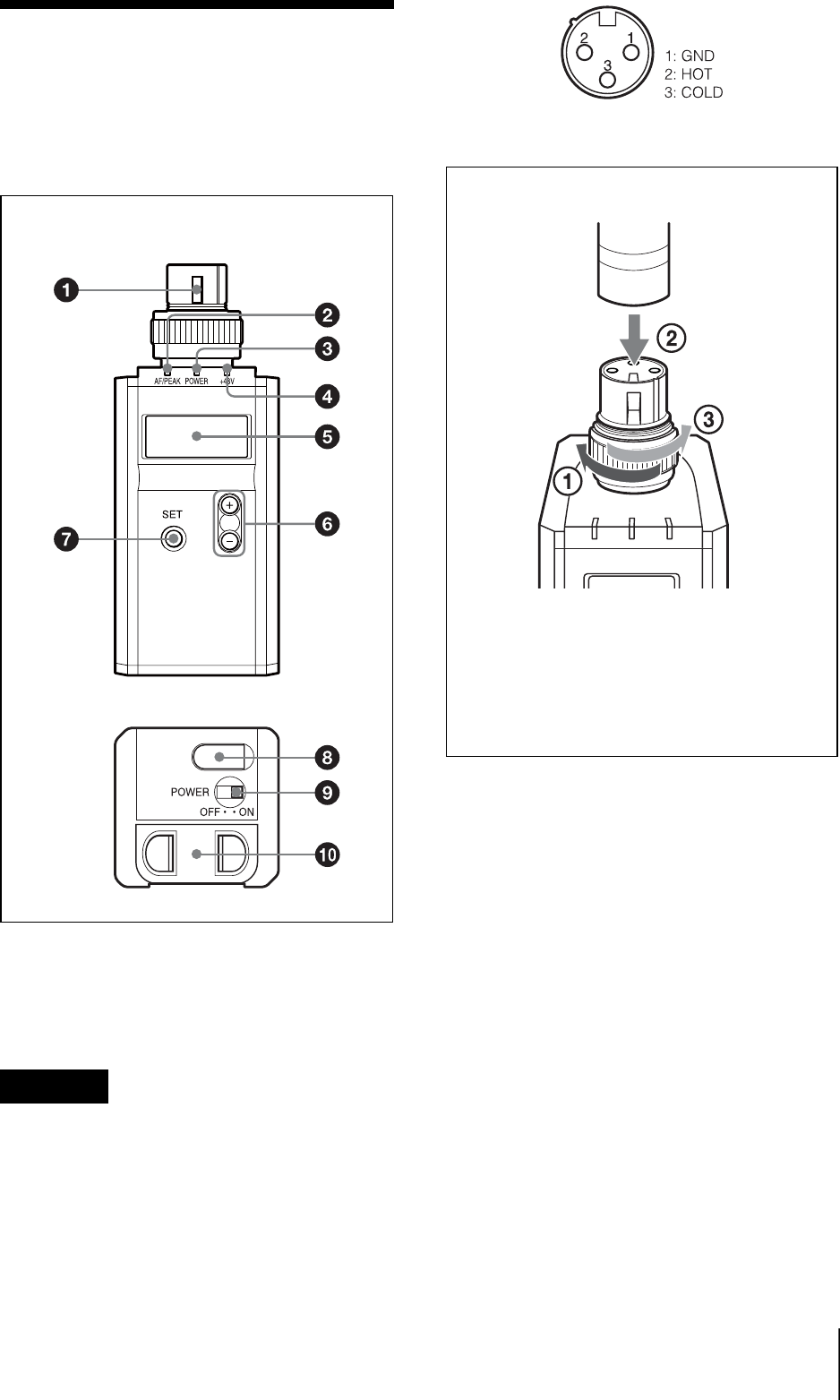
Parts
Identification
aAudio input connector (XLR-3-11C)
Connects a microphone with an XLR-3-
12C-type output connector or an audio
cable with an XLR-3-12C-type connector.
Be sure that the transmitter is turned off
before connecting a microphone or cable to
the transmitter.
To connect a microphone or a cable
bAF (audio input level) /PEAK
indicator
Lights up green when the signal input is
stronger than the reference level.
Lights up red when the signal input is 3 dB
below the level at which distortion begins.
cPOWER indicator
Lights up green when the transmitter is
turned on. When the battery is exhausted,
the indicator starts flashing.
d+48V indicator
Lights up when INPUT LEVEL is set to
MIC and +48 V power is being supplied to
a connected microphone or other device.
Caution
Front
Bottom
Microphone or a cable (optional)
Turn the connector ring clockwise (1)
and insert the microphone or cable
connector into the audio input connector
until it is fully engaged (2). Then turn the
connector ring counterclockwise to
secure the latch (3).
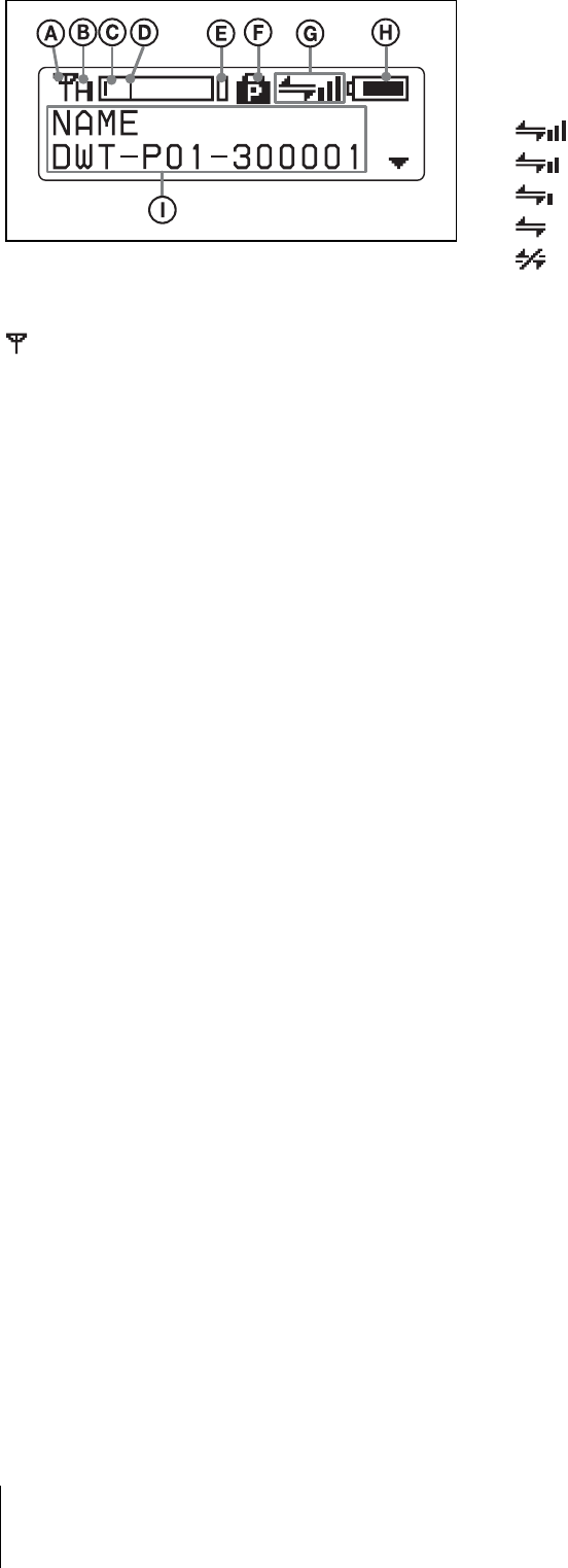
eDisplay section
ARF transmission indication
Indicates the current transmission status.
:Currently transmitting
—: Transmission stopped
BRF (radio frequency) transmission
power indication
Indicates the current transmission power
setting. You can change the setting with the
RF POWER function.
H: Transmitting at 50 mW
M: Transmitting at 10 mW
L: Transmitting at 1 mW
CAudio input level meter
Indicates the input signal level of the audio
input connector.
DReference level gauge
Indicates the reference input level. When
the attenuation is 0 dB with INPUT LEVEL
set to MIC, –58 dBu (–60 dBV) is indicated.
When LINE is selected for INPUT LEVEL,
+4 dBu is indicated.
EPeak indicator
Warns of excessive input by lighting up
when the signal is 3 dB below the level at
which distortion begins.
FPOWER switch lock indicator
Indicates that the POWER switch is locked,
preventing the transmitter from being
accidentally turned off or on.
For details, see “Locking the POWER switch
(POWER SW LOCK)”.
GWireless remote control condition
indication
Indicates the signal transmission condition
of the wireless remote control function (4
levels).
: Good transmission
: Somewhat good transmission
: Somewhat poor transmission
: Poor transmission
: Unable to communicate with paired
receiver
When the wireless remote control function
is off, this indication does not appear.
HBattery indication
Shows the battery condition.
For details, see “Battery indication”.
IMenu display section
The status of 17 different functions are
displayed here. To select the function, press
the + or – button repeatedly.
For details, See “Setting Menus”.
f + or – button
Selects functions or values shown on the
display.
Holding down the – button while switching
on the transmitter activates the pairing
operation for the wireless remote control
function.
gSET button
Adjusts displayed function settings and
enters the value.
Holding down the SET button while
switching on the power turns the transmitter
on without sending a signal.
hUSB connector (Micro USB)
Use this connector to connect an optional
USB keyboard to carry out menu functions
using key operations. By connecting the
digital wireless receiver to this connector
with the supplied USB cable, you can

exchange the encryption key for encrypted
transmission function.
iPOWER switch
Turns the transmitter ON or OFF.
jBattery compartment
Accommodates two LR6 (size AA) alkaline
batteries.
For details on how to insert the batteries, see
“Power Supply”.
Power Supply
The transmitter can operate on two LR6
(size AA) alkaline batteries continuously
for about 3.5 hours at 25°C (77°F).
Installing the batteries
1Squeeze the battery-holder tabs inward
(in the direction of the arrows) and
slide out the battery holder.
2Insert new batteries, making sure the
polarities are correct, and then return
the battery holder to its original
position.
Battery indication
The power status is indicated by eight level
indications.
Replace both batteries when the battery
indication starts to flash.
Be sure to check the expiration date printed
on the new batteries before using them.

The indication is based on the use of new
LR6 (size AA) Sony Alkaline batteries. An
incorrect indication may result when a
different kind of batteries, a different brand
of batteries or old batteries are used. If you
plan to use the transmitter for a long period
of time, it is recommended that you replace
the batteries with brand new ones.
Setting the
Transmission
Channel
The transmitter provides groups of
interference-free channels. When using
multiple microphones and transmitters at
the same time (simultaneous multi-channel
operations) within the same area, selecting
the same group and using a channel within
that group can prevent signal interference.
To set the transmission channel on the
transmitter, first you select the group and
channel using the RF indicator and
scanning functions on the receiver. Next
you set the group and channel parameters to
match the setting on the receiver.
Selecting the group/
channel
• Before doing this procedure, use the
BAND function to set the
transmitter to the bandwidth of the
receiver you are using.
• The setting for this function cannot be
changed during actual signal
transmission.
Set the transmitter group (GP) and channel
(CH) as follows:
For details on groups and channels, refer to “Sony
Digital Wireless Microphone System Frequency
Lists” on the supplied CD-ROM.
For details on menu operation, see “Basic Menu
Operations”.
Note
Notes

1Turn off the power, and then while
holding down the SET button, turn the
power on.
The signal transmission stops.
2Press the + or – button repeatedly until
the GP/CH indication is displayed.
3Hold down the SET button until the
group indication flashes.
4Press the + or – button repeatedly to
select a group.
5Press the SET button to enter the
group.
The channel indication starts flashing.
6Press the + or – button repeatedly to
select a channel.
7Press the SET button to enter the
channel.
To set the group/channel
using the pairing mode of the
wireless remote control
function
When the transmitter is paired with the
receiver, the transmission channel of the
transmitter is set to the receiving channel on
the receiver automatically.
For details, see“Pairing with a receiver”.
Using the
Wireless Remote
Control Function
This transmitter is equipped with a wireless
remote control function that can be used to
set the parameters (low-cut filter,
attenuation operation, power save mode,
etc.) of the transmitter through the receiver
or other devices. This function makes it
easier to operate and manage the
microphone system while in the field.
This wireless control is 2.4 GHz
IEEE802.15.4 compliant and has no effect
on the RF band of digital wireless audio.
This function is activated when pairing is
established between the transmitter and the
receiver using the RF REMOTE function.
Pairing must be done first before the
wireless remote control function can be
used.
Pairing with a receiver
Pairing links the transmitter with the
receiver which the wireless remote control
function is to be used.
When the transmitter has been paired with a
receiver through the receiver operation,
turning on the transmitter while holding
down the – button establishes the pairing
immediately.
To carry out pairing through menu
operations on the transmitter, do the
following.
1Set the receiver to be used for
controlling the transmitter to pairing
mode.

For details on receiver operations, refer to the
operating instructions supplied with the
receiver.
2Press the + or – button repeatedly until
the RF REMOTE indication is
displayed.
3Hold down the SET button until the
item to be set flashes.
4Press the + or – button repeatedly to
select PAIRING.
5Press the SET button to enter.
The transmitter sends a pairing request
to the receiver which is on pairing
mode.
Before established pairing, if you press
any operation key on the transmitter,
pairing mode will be cancelled.
When pairing has been established, the
wireless remote control condition level
(indicated by ) goes up, the RF
REMOTE function turns on, and the
remote control function becomes
operative.
To use the wireless remote
control function with a
previous pairing
In the RF REMOTE indication, select ON.
• When you set RF REMOTE to ON, the
transmitter will communicate with the
receiver to which it was previously
paired. To use the wireless remote
control function with another receiver,
you must perform the pairing procedure
for that receiver.
• Multiple transmitters cannot be paired
with the same receiver.
The following transmitter settings
can be done from the wireless
remote control:
• Group/channel/BAND setting
• RF transmission power setting
• Attenuator for the audio input setting
• Low-cut filter setting
• Power save setting
• +48 V power supply setting
For details on menu operation, see “Setting Menus”.
To cancel the wireless remote
control function
In the RF REMOTE indication, select OFF.
Notes on the wireless remote
control function
The wireless remote control function on the
transmitter uses the 2.4-GHz band and may
thus be subject to interference from other
devices.
• When pairing fails (“Pairing fail” is
displayed), successful communication
between the transmitter and the receiver
has not occurred within a given amount
of time. Pairing may be harder to do
when another receiver is engaged in
pairing nearby.
• When it becomes hard to use the remote
control, the remote control may be
improved by switching the wireless
remote control function off, then on again
in the RF REMOTE indication, then re-
pairing with the transmitter (change to a
channel with less interference).
Notes

Using the
Encrypted
Transmission
Function
To prevent hacking of the signal, the
transmitter scrambles the signal during
transmission. To use this function, select
one of the following encrypted transmission
modes:
Secure key mode: An encryption key
that is automatically generated by the
transmitter is used by both the transmitter
and receiver in this one-to-one encrypted
transmission method.
Password mode: You choose a
password of up to eight characters that can
be set for multiple transmitters and
receivers. This enables encrypted
transmission within a group.
Make sure the same mode is set on the
transmitter and receiver.
Using secure key mode
(SECURE KEY)
Use this mode for one-to-one encrypted
transmission between one transmitter and
one receiver.
An encryption key that cannot be read from
the outside is automatically generated by
the transmitter. This key is transmitted to
the receiver through a USB connection or
the RF REMOTE function, enabling
encrypted transmission to take place.
The encryption key used by the transmitter
and receiver is newly generated for each
key transmission, resulting in highly secure
communication.
The encryption key used between the
transmitter and the receiver is saved when
the power is turned off, so the encrypted
transmission can be resumed the next time
the power is turned on.
1Preparing the transmitter (this unit)
1Hold down the SET button until
the item to be set flashes in the
ENCRYPTION indication on the
transmitter.
2Press the + or – button repeatedly
to select SECURE KEY, and then
press the SET button.
2Preparing the receiver
Select SECURE KEY on the receiver
that receives the encryption key.
For details on receiver operations, refer to the
operating instructions supplied with the
receiver.
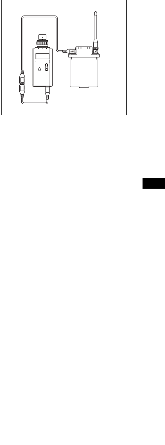
3Exchanging the encryption key
On the receiver, select USB or
REMOTE (wireless remote) as the
method for encryption key exchange.
When the RF REMOTE function is
off, REMOTE cannot be selected.
When you select USB:
Connect the transmitter to the receiver
with the supplied USB cable and USB
adapter cable.
Note
For details on receiver operations, refer to the
operating instructions supplied with the
receiver.
When you select REMOTE:
The transmitter searches for a receiver
that it has been paired with. After the
transmitter detects the receiver, the
transmitter exchanges the encryption
key with receiver and encrypted
transmission begins.
Using password mode
(PASSWORD)
Set this mode when multiple transmitters
are paired with multiple receivers for
encrypted transmission.
If both transmitters and receivers are set
with the same user-designated password,
the audio signal can be decoded. This mode
is useful when multiple transmitters and
receivers are used as a single group, or
when the audio signal from one transmitter
is received by multiple receivers at the same
time.
1Hold down the SET button until the
item to be set flashes in the
ENCRYPTION indication on the
transmitter.
2Press the + or – button repeatedly to
select PASSWORD, and then press the
SET button.
3Input a password of up to eight
characters on the transmitter.
To enter a password, use the procedure
described in “Naming of transmitter (NAME)”
on page 25.
4Set the encrypted transmission
function setting on the receiver to
PASSWORD.
5Set the same password that was set on
the transmitter.
For details on receiver operations, refer to the
operating instructions supplied with the
receiver.
It is recommended that you change the
password periodically.
USB cable (supplied)
USB adapter cable
(supplied)
Note
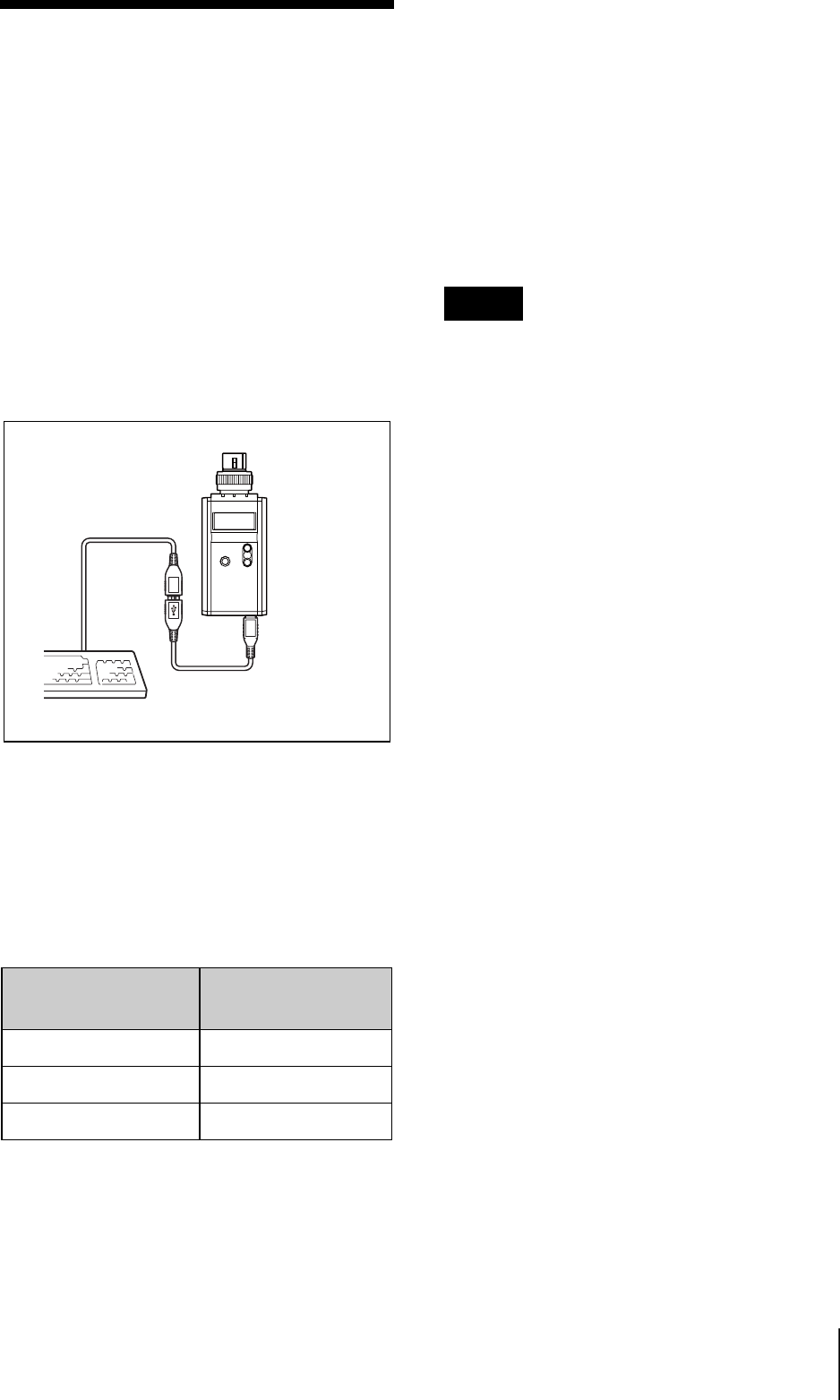
Using a USB
Keyboard
Connecting an optional USB keyboard to
the transmitter allows you to perform menu
operations and enter your name and
password for the encrypted transmission
function from the keyboard.
A Micro USB connector is used on the
transmitter. For this reason, use the supplied
USB adapter cable.
Menu operations with a USB
keyboard
You can use a USB keyboard to perform the
same menu operations that you do on the
transmitter.
The transmitter buttons correspond to the
following keys on a USB keyboard:
To enter a text
With a USB keyboard, you can enter names
and passwords for encrypted transmissions.
Characters that can be entered from
a USB keyboard: (space), 0, 1, 2, 3, 4, 5,
6, 7, 8, 9, A, B, C, D, E, F, G, H, I, J, K, L,
M, N, O, P, Q, R, S, T, U, V, W, X, Y, Z, !,
#, &, $, @, +, -, =, _, (, ), [, ]
(Passwords may consist of the numbers 0 to
9 and letters A to Z only.)
Special key: Backspace (BS) and Delete
(DEL) keys.
• The number keys on the keyboard cannot
be used.
• This transmitter is compatible with
English-language keyboards only.
• USB keyboards with multiple functions,
such as USB hub and pointing device,
cannot be used.
• Power to the connected keyboard is
supplied by the USB connector on the
transmitter. The power rating is 100 mA.
Keyboards that consume more power
than that cannot be used.
• Do not leave the transmitter connected to
the keyboard when not in use. If you do,
the batteries in the transmitter will be
drained more quickly.
• Text editing should be done with the
alphabet, BS, DEL, and Enter keys.
Buttons on the
transmitter
USB keyboard
SET ENTER
+R
–r
USB adapter cable
(supplied)
Notes

Basic Menu
Operations
1Press the + or – button repeatedly until
the function to be set appears.
2Hold down the SET button until the
item to be set flashes.
3Press the + or – button to change the
setting.
4Press the SET button to enter the
setting.
Types of menu:
• NAME (transmitter name) setting
• BAND (frequency band) selection
• GP/CH (group/channel) selection
• RF POWER (RF transmission power)
setting
• INPUT LEVEL (audio input level)
setting
• LCF (low-cut filter) setting
• POWER SAVE setting
• TIME (accumulated use time) indication
• +48V (+48 V power supply) setting
• ENCRYPTION (encrypted transmission
function) setting
• INTERNAL SG (internal signal
generator)
• POWER SW LOCK (POWER switch
lock) function
• RF REMOTE (wireless remote control)
function
• BRIGHTNESS (display brightness)
setting
• DIMMER MODE (automatic dimming
of the display) setting
• FACTORY PRESET (factory setting)
function
• VERSION (software version) indication
Function name
Item to be set

Setting Menus
The functions and parameters of the settings
menu are explained here. Underlined items
are the factory setting.
Naming of transmitter
(NAME)
You can specify a transmitter name of up to
16 characters. The factory setting for the
transmitter name is the model name and
serial number. The transmitter name is sent
to the receiver as metadata and is used by
the receiver to distinguish between different
transmitters.
+: The first press on the + button displays
the character set. You can then use the + and
– buttons to select the desired character.
And then, pressing the SET button adds the
selected character to the end of the current
name.
– : Deletes the last character in the current
name.
SET: Enters the character or edited name.
You cannot insert or delete a character in
the middle of the name.
To edit with a keyboard
You can enter data from an optional
keyboard connected to the USB connector.
For details, see “Using a USB Keyboard”.
Selecting the group/
channel (GP/CH)
The factory settings are as follows:
00 Gp
For details, see “Selecting the group/channel”.
Selecting the frequency
band (BAND)
Match the frequency range on this
transmitter to that of the Sony digital
wireless receiver.
The frequency range that can be set for the
optional receiver combined with this
transmitter differs as follows:
Example
TV30-33, TV34-36, TV38-41
Not available for TV37
6267CE
TV62-64, TV67-69
Not available for TV65 and TV66
For details on the frequency range of each band,
refer to “Sony Digital Wireless Microphone System
Frequency Lists” on the supplied CD-ROM.
Using wireless remote control, this function
can be controlled from the receiver and
other devices.
For details on wireless remote control function, see
“Using the Wireless Remote Control Function” on
page 19.
Note
The setting for this function cannot be
changed during actual signal transmission.
To change the setting, turn off the
transmitter first. Then, while holding down
the SET button, turn the power on. And
then, change the setting after the signal
transmission has stopped.
Setting the RF output
power (RF POWER)
You can set the RF output power.
1 mW (LOW): Transmitted by 1 mW
10 mW (MID): Transmitted by 10 mW
50 mW (HIGH): Transmitted by 50 mW
Using wireless remote control, this function
can be controlled from the receiver and
other devices.
For details on wireless remote control function, see
“Using the Wireless Remote Control Function”.
The setting for this function cannot be
changed during actual signal transmission.
To change the setting, turn off the
transmitter first. Then, while holding down
the SET button, turn the power on. And
then, change the setting after the signal
transmission has stopped.
Setting the audio input
level (INPUT LEVEL)
You can set the input level to an analog
head amp.
Select LINE or MIC, depending on the
audio source connected to the audio input
connecter.
When MIC is selected, ATT (attenuation
level) will flash next. With the microphone
connected, speak into the microphone as
you monitor the audio input level meter and
press the + or – button repeatedly to select
the appropriate attenuation level.
The reference levels for the various settings
are as follows:
With the wireless remote control function, the attenuation level can be changed from the
receiver and other devices.
For details on wireless remote control function, see “Using the Wireless Remote Control Function”.
Note Note
Input Attenuation
(dB)
Reference input
level (dB)
Maximum input
level (dBu)
Headroom (dB)
MIC 0–58 –22 36
3–55 –19
6–52 –16
9–49 –13
3 dB step 3 dB step 3 dB step
45 –13 +23
48 –10 +24 34
LINE –+4 +24 20

Low-cut filter setting (LCF)
The frequency of the low-cut filter can be
set.
OFF:Turns off the low-cut filter.
20 30 40 50 60 70 80 90 100
120 140 160 180 200 220 (Hz):
Low-cut filter is set according to the
selected frequency.
Using wireless remote control, this function
can be controlled from the receiver and
other devices.
For details on wireless remote control function, see
“Using the Wireless Remote Control Function”.
Power save setting (POWER
SAVE)
To conserve power, this setting allows you
to put all transmitter functions to sleep.
ACTIVE:The transmitter operates
normally.
SLEEP: The sleep function is on. During
sleep, the POWER indicator flashes at 2-
second intervals.
To change back to normal
operation
During sleep, press the SET, +, or – button.
You can also use the wireless remote
control to change the receiver back to
normal operation.
For details on wireless remote control function, see
“Using the Wireless Remote Control Function”.
Displaying the
accumulated use time (TIME)
You can display the accumulated battery
use time as a rough estimate of total
transmitter usage.
The factory setting is “00:00”.
To reset the accumulated time
indication
1Hold down the SET button until the
time indication flashes.
2Press the – button so “00:00 RESET”
appears, and then press the SET
button.
+48 V power supply setting
(+48V)
You can turn the +48 V power supply on or
off for microphones that require an external
power supply.
OFF:Power is not supplied to the
connected microphone.
ON: Power is supplied to the connected
microphone.
Using wireless remote control, this function
can be controlled from the receiver and
other devices.
For details on wireless remote control function, see
“Using the Wireless Remote Control Function”.
The +48 V power supply can be turned on
or off, regardless of INPUT LEVEL setting.
Note, however, that the +48 V power is
actually supplied only when INPUT
LEVEL is set to MIC.
Note

Setting the encrypted
transmission function
(ENCRYPTION)
You can set the encrypted transmission
function.
SECURE KEY: Sets the secure key
method.
PASSWORD: Sets the password method.
OFF: The encrypted transmission function
is not used.
For details, see “Using the Encrypted Transmission
Function”.
Generating an internal
signal (INTERNAL SG)
This transmitter generates a 1-kHz
reference level sine wave that can be used to
adjust or check the audio level of the
receiver or the system that you are using.
This internal signal is outside the control of
the attenuator.
1 kHz: A 1-kHz internal signal is
generated.
OFF: An internal signal is not generated.
If the transmitter is turned off while
INTERNAL SG is set to 1 kHz, the setting
will revert to OFF automatically.
Locking the POWER switch
(POWER SW LOCK)
The POWER switch can be locked to
prevent the transmitter from being
accidentally turned off or on.
Even when the POWER switch is locked,
all parts of the transmitter other than the
POWER switch remain functional.
UNLOCK:The POWER switch is not
locked.
LOCK: The POWER switch is locked.
When LOCK is selected, the POWER
switch lock indicator appears in the display.
Wireless remote control
function (RF REMOTE)
This function must be set to allow the
wireless remote control function to be used
between the transmitter and receiver.
OFF: Stops the wireless remote control
function.
ON: Starts the wireless remote control
function with the previously paired
receiver.
PAIRING: Executes a new pairing.
For details, see “Pairing with a receiver”.
Setting the brightness of
the display (BRIGHTNESS)
Ten levels of brightness can be selected for
the organic light-emitting diode display.
The selectable settings are the following:
(Dark) 1 2 3 4 5 6 7 8 9 10 (Bright)
Automatic dimming of the
display (DIMMER MODE)
The organic light-emitting diode display
can be set to dim or turn off after a certain
amount of time.
AUTO OFF: The display turns off after 30
seconds. The display goes on again when
you press the SET, +, or – button.
AUTO DIMMER: The display dims after
30 seconds. The display becomes bright
again when you press the SET, +, or –
button.
Note

ALWAYS ON: The display stays on at the
brightness level set with the BRIGHTNESS
function.
Resetting parameters to
their factory settings
(FACTORY PRESET)
All parameter settings can be returned to
their factory settings.
Holding down the SET button until a
message appears asking for confirmation.
Press the + or – button repeatedly to select
YES, and then press the SET button to
enter. The transmitter parameters are reset
to their factory settings.
The setting for this function cannot be
changed during actual signal transmission.
To change the setting, turn off the power
first. Then while holding down the SET
button, turn the power on. And then, change
the setting after the signal transmission has
stopped.
Displaying the software
version (VERSION)
The version of the transmitter software can
be displayed.
Note

Troubleshooting
If you encounter a problem using this transmitter, use the following checklist to find a
solution. For any problems with the receiver or adapter, refer to the operating instructions
supplied with the respective device. If the problem persists, consult your Sony dealer.
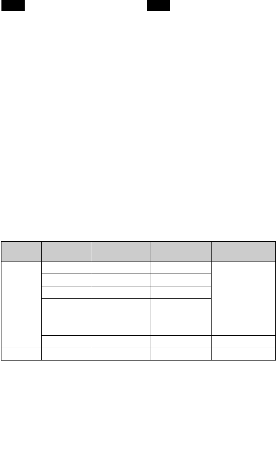
Symptom Meanings Remedy
The transmitter
does not turn
on.
The batteries are inserted
backwards in the battery
compartment.
Reinsert the batteries with the
correct orientation.
The batteries are exhausted. Replace the batteries with new
ones.
The batteries
drain quickly.
Manganese batteries are being
used.
Use alkaline batteries.
The transmitter is being used
under cold conditions.
The batteries drain quickly under
cold conditions.
Interruptions in
the reception
occurs.
The transmitter is too far from
the receiver.
Decrease the distance to the
receiver and check the reception.
The RF output power setting is
set to 1 mW (LOW).
Increase the RF output power.
There is no
sound.
The channel setting on the
transmitter is different from that
on the receiver.
Use the same channel setting on
both the transmitter and receiver.
The setting of the encrypted
transmission function on the
receiver is different from that on
the transmitter.
Confirm that the setting of the
encrypted transmission function is
the same on both the transmitter
and the receiver.
The sound is
weak.
The audio input level of the
transmitter is set to LINE or the
attenuation level is too high.
If a microphone is connected to
the transmitter, set the audio input
to MIC. While monitoring the audio
input level meter, set the
attenuator to an appropriate level.
There is
distortion in the
sound.
The attenuator is set too low for
the audio input level of the
transmitter.
While monitoring the audio input
level meter, set the attenuator to a
level that does not produce
distortion.
The bass is
weak.
The frequency of the low-cut
filter is set too high.
While monitoring the sound,
decrease the low-cut filter
frequency to a level that produces
the proper sound quality.

There is too
much bass.
The microphone connected to
the transmitter produces
excessive bass because the
frequency response of the
transmitter extends into the low
20-Hz range.
Use the low-cut filter to cut the
bass.
The power
does not turn
off even though
the POWER
switch is turned
to OFF.
The POWER switch is locked. Turn off the POWER switch locking
function.
Wireless
remote control
is not possible.
Pairing has not been established
between the transmitter and
receiver.
Carry out pairing (see page 19).
The receiver is too far from the
transmitter for communication to
occur.
Check the wireless remote control
condition level. If it is low,
decrease the distance between
the transmitter and the receiver.
The transmitter that was paired
with the receiver has been
paired with another receiver.
On the receiver, carry out pairing
again with the transmitter that you
want to control.
The USB
keyboard does
not work.
You are using a USB keyboard
that is not compatible with the
transmitter.
Check the conditions for using a
USB keyboard with the transmitter.
The display is
too dark.
The display brightness is set to
low.
Adjust the brightness of the display.
Symptom Meanings Remedy

Important Notes
on Operation
Notes on using the
transmitter
• The digital wireless microphone system
product must be used within a
temperature range of 0°C to 50°C (32°F
to 122°F).
• Operating the transmitter near electrical
equipment (motors, transformers, or
dimmers) may cause it to be affected by
electromagnetic induction. Keep the
transmitter as far from such equipment as
possible.
• The presence of the lighting equipment
may produce electrical interference over
the entire frequency range. Position the
transmitter so that interference is
minimized.
• To avoid degradation of the signal-to-
noise ratio, do not use the transmitter in
noisy places or in locations subject to
vibration, such as the following:
- near electrical equipment, such as
motors, transformers or dimmers
- near air conditioning equipment or
places subject to direct air flow from
an air conditioner
- near public address loudspeakers
- where adjacent equipment might
knock against the tuner
Keep the transmitter as far from such
equipment as possible or use buffering
material.
On cleaning
• If the transmitter is used in a very humid
or dusty place or in a place subject to an
active gas, clean its surface as well as the
connectors with a dry, soft cloth soon
after use. Lengthy use of the transmitter
in such places or not cleaning it after its
use in such places may shorten its life.
• Clean the surface and the connectors of
the transmitter with a dry, soft cloth.
Never use thinner, benzene, alcohol or
any other chemicals, since these may mar
the finish.
Notes on simultaneous multi-
channel operation
• Keep the transmitter at least 30
centimeters (11 7/8inches) away from
another transmitter.
• When only digital wireless microphones
are being used, keep the transmitter at
least 4 meters (13 feet) away from the
antenna of a receiver for up to 10
channels, and at least 6 meters (20 feet)
away for 11 or more channels.
• When a mixture of digital and analog
wireless microphones is being used, keep
the transmitter at least 6 meters (20 feet)
away from the antenna of a receiver.
• This system should be kept at least 100
meters (328 feet) away from any analog
wireless systems using the same
frequency when both are being used in a
wide area with no walls or obstructions.
• If you experience noise, increase the
distance between the transmitter and
receiver or decrease the transmission
power on the transmitter.
Note on microphone and
transmitter combinations
It is recommended that you use the Sony
ECM-673/674/678 Electret Condenser
Microphone with this transmitter. The
transmission signal may cause noise on
some microphones. If you experience noise,

you may be able to reduce it by lowering the
transmission power. Specifications
Transmitting section
Oscillator type
Crystal-controlled PLL synthesizer
Carrier frequencies
470.125 to 607.875 MHz
614.125 to 697.875MHz
U4250: 638 to 698 MHz (TV-42 to
TV-51 channels)
European model:
CE6267: 798 to 822 MHz (TV-62
to TV-64 channels); 838 to 862
MHz (TV-67 to TV-69
channels)
Channel step : 125kHz
European model:
CE6267: 25 kHz
RF power output
1 mW/10 mW/50 mW (e.r.p)
selectable
Occupied RF bandwidth
192 kHz or less
Audio delay
1.5 ms
Transmission frequency stability level
±6.5 ppm
Type of emission
G1E or G1D
Modulation method
π/4 Shift QPSK
Audio section
Maximum input level
MIC: –22 dBu (with 0 dB
attenuator)
LINE: +24 dBu
To prevent electromagnetic
interference from portable
communication devices
The use of portable telephones and
other communication devices near
the DWT-P01 may result in
malfunction and interference with
audio signals. It is recommended that
portable communication devices near
the DWT-P01 be turned off.
Audio attenuator adjustment range (pad)
0 to 48 dB (3-dB steps, MIC input
mode only)
Microphone input connector
XLR-3-11C (female)
Input impedance
4.7 kohms or more
Frequency response
20 Hz to 22 kHz
T.H.D 0.03% or less
Dynamic range
106 dB or more
0 dBu = 0.775 V
General
Operating voltage
3 V DC, with two LR6 (AA)
alkaline batteries
Battery life
Continuous operating time
3.5 hours (at 25 °C (77 °F), 10-mW
output using Sony LR6 (AA)-
size alkaline batteries with the
wireless remote control
function off, DIMMER MODE
set to AUTO OFF, and +48V
set to OFF)
Operating temperature
0 to 50 °C (32 to 122 °F)
Storage temperature
–20 to +60 °C (–4 to +140 °F)
Wireless remote control
2.4-GHz 1EEE802.15.4 compliant
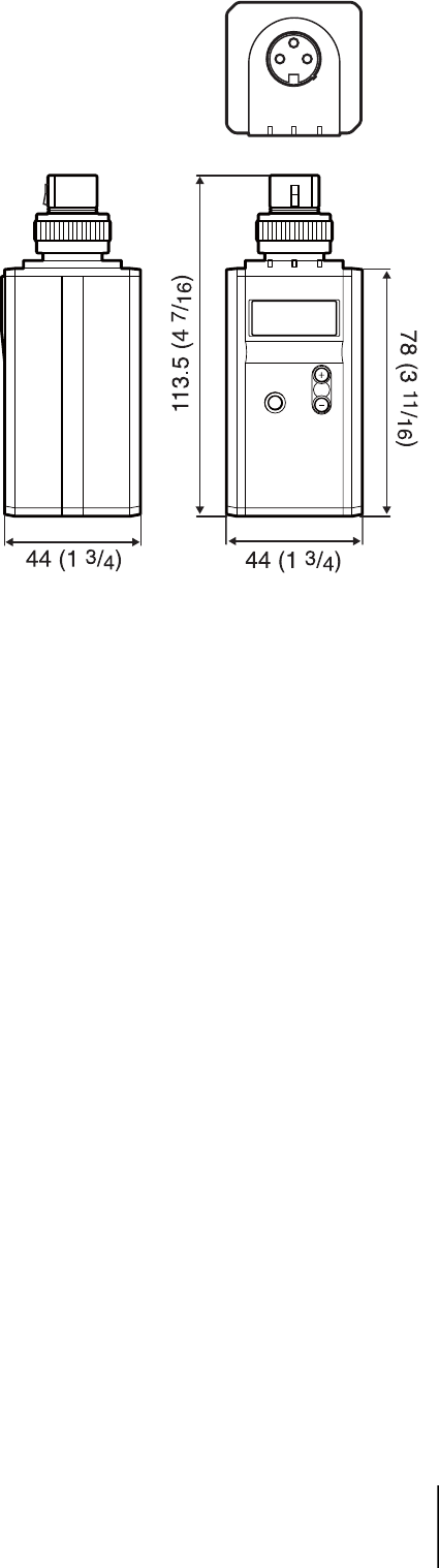
Dimensions (unit: mm (inches))
Mass Approx. 245 g (8.6 oz) including
batteries
Supplied accessories
Spare battery case (1)
Soft case (1)
USB adapter cable (1)
USB cable (1)
Operating Instructions (1)
CD-ROM (1)
Optional accessories
ECM-673/674/678 Electret
Condenser Microphone
Design and specifications are subject to
change without notice.