Sony Group PCG571Z Notebook Computer with WLAN and Bluetooth User Manual OEM installation manual Calexico 2
Sony Corporation Notebook Computer with WLAN and Bluetooth OEM installation manual Calexico 2
UserManual.wiki
>
Sony Group
>
PCG571Z User Manual
>
OEM installation manual Calexico 2
Contents
1.
Instruction Manual
2.
Users manual
3.
OEM installation manual Calexico 1
4.
OEM Installation Manual CX1
5.
OEM installation manual Calexico 2
6.
OEM Installtion Manual Modular Manual Recommendations laptop
OEM installation manual Calexico 2
Navigation menu
Upload a User Manual
Namespaces
Wiki Guide
HTML
PDF
Info
Views
User Manual
Discussion / Help
Navigation
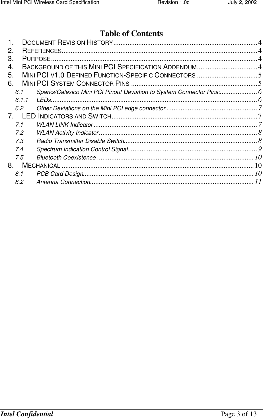
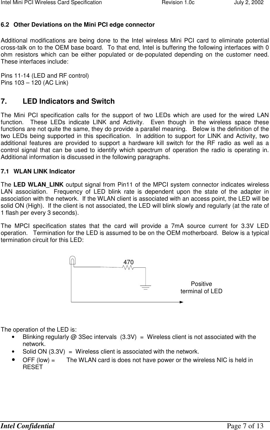
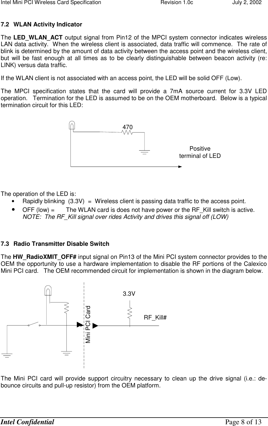
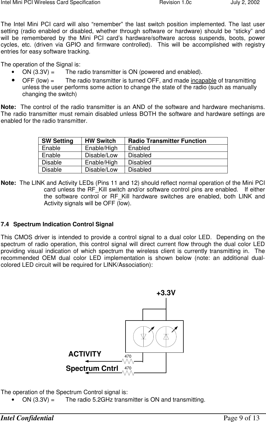
![Intel Mini PCI Wireless Card Specification Revision 1.0c July 2, 2002 Intel Confidential Page 5 of 13 5. Mini PCI v1.0 Defined Function-Specific Connectors The MPCI specification defines function-specific connectors on the MPCI card for Wired LAN and Modem functionality. • The function-specific LAN connector. This is a 14-pin connector. • The function-specific Modem connector. This is a 2-pin connector. After reviewing next generation board layouts as well as the customer drive for more and more capability while driving smaller form factors, the 14 pin I/O connector will no longer be supported on Intel wireless Mini PCI cards going forward. Intel will continue to support the two-pin connector for support of an AC’97 modem. 6. Mini PCI System Connector Pins The Mini PCI edge connector pinout definition as described in the Mini PCI Specification, Revision 1.0, is shown below. The Intel wireless Mini PCI card will comply to this pinout for compatibility purposes except for deviations as noted in this section. Table 1: Mini PCI Card Type III System Connector Pinout Pin Signal Pin Signal Pin Signal Pin Signal 1 TIP 2 RING 63 3.3V 64 FRAME# KEY KEY 65 CLKRUN# 66 TRDY# 3 8PMJ-3 4 8PMJ-1 67 SERR# 68 STOP# 5 8PMJ-6 6 8PMJ-2 69 GROUND 70 3.3V 7 8PMJ-7 8 8PMJ-4 71 PERR# 72 DEVSEL# 9 8PMJ-8 10 8PMJ-5 73 C/BE[1]# 74 GROUND 11 LED1_GRNP 12 LED2_YELP 75 AD[14] 76 AD[15] 13 LED1_GRNN 14 LED2_YELN 77 GROUND 78 AD[13] 15 CHSGND 16 RESERVED 79 AD[12] 80 AD[11] 17 INTB# 18 5V 81 AD[10] 82 GROUND 19 3.3V 20 INTA# 83 GROUND 84 AD[09] 21 RESERVED 22 RESERVED 85 AD[08] 86 C/BE[0]# 23 GROUND 24 3.3VAUX 87 AD[07] 88 3.3V 25 CLK 26 RST# 89 3.3V 90 AD[06] 27 GROUND 28 3.3V 91 AD[05] 92 AD[04] 29 REQ# 30 GNT# 93 RESERVED 94 AD[02] 31 3.3V 32 GROUND 95 AD[03] 96 AD[00] 33 AD[31] 34 PME# 97 5V 98 RESERVED_WIP 4 35 AD[29] 36 RESERVED 99 AD[01] 100 RESERVED_WIP 4 37 GROUND 38 AD[30] 101 GROUND 102 GROUND 39 AD[27] 40 3.3V 103 AC_SYNC 104 M66EN 41 AD[25] 42 AD[28] 105 AC_SDATA_IN 106 AC_SDATA_OUT 43 RESERVED 44 AD[26] 107 AC_BIT_CLK 108 AC_CODEC_ID0# 45 C/BE[3]# 46 AD[24] 109 AC_CODEC_ID1# 110 AC_RESET# 47 AD[23] 48 IDSEL 111 MOD_AUDIO_MON 112 RESERVED 49 GROUND 50 GROUND 113 AUDIO_GND 114 GROUND 51 AD[21] 52 AD[22] 115 SYS_AUDIO_OUT 116 SYS_AUDIO_IN 53 AD[19] 54 AD[20] 117 SYS_AUDIO_OUT 118 SYS_AUDIO_IN](https://usermanual.wiki/Sony-Group/PCG571Z.OEM-installation-manual-Calexico-2/User-Guide-328877-Page-5.png)
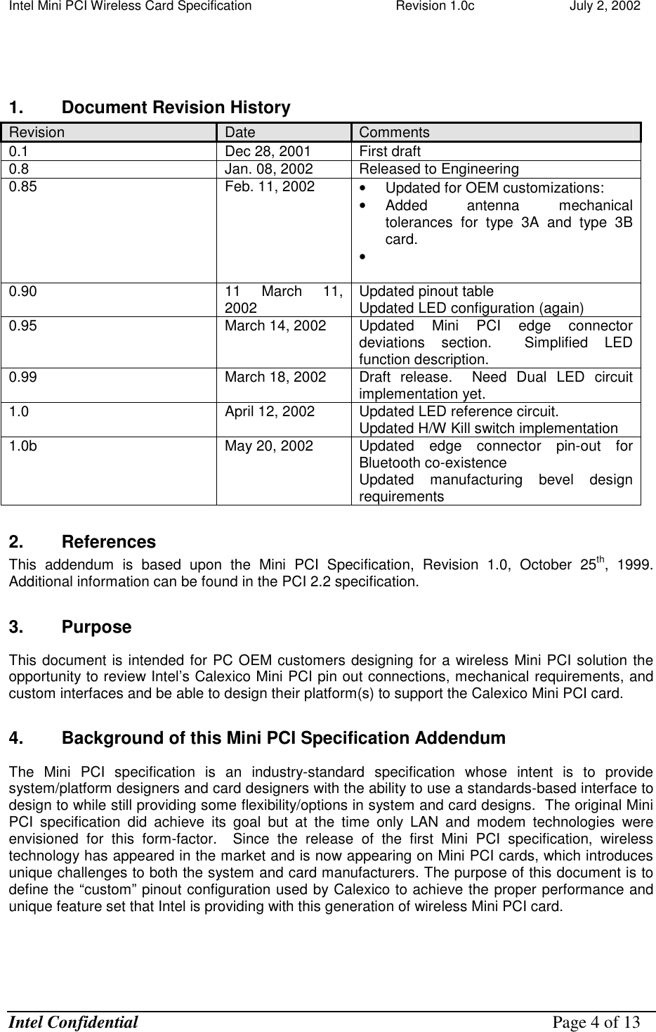
![Intel Mini PCI Wireless Card Specification Revision 1.0c July 2, 2002 Intel Confidential Page 6 of 13 GND GND 55 GROUND 56 PAR 119 AUDIO_GND 120 AUDIO_GND 57 AD[17] 58 AD[18] 121 RESERVED 122 MPCIACT# 59 C/BE[2]# 60 AD[16] 123 VCC5VA 124 3.3VAUX 61 IRDY# 62 GROUND 6.1 Sparks/Calexico Mini PCI Pinout Deviation to System Connector Pins: 6.1.1 LEDs PIN Old Signal Name New Signal Name Signal Definition . 11 LED1_GRNP LED_WLAN_LINK Active-high LED drive signal provides an indication of access point association. This signal will blink slowly every 3 seconds until association occurs at which time it will be HIGH until association is lost. During initialization or while the radios are in reset, the signal will be LOW. Note: 0 ohm series resistor provides connection to the Mini PCI edge connector 12 LED2_YELP LED_WLAN_ACT Active-high LED drive signal provides an indication of data activity. This signal will blink rapidly when data traffic is occurring. During initialization, or while the radios are in reset, or if the client is not associated with an access point the signal will be LOW. Note: 0 ohm series resistor provides connection to the Mini PCI edge connector 13 LED1_GRNN HW_RadioXMIT_OFF# Active low input from a hardware switch to the card to disable the radio from transmitting. See further description in this document. Note: 0 ohm series resistor provides connection to the Mini PCI edge connector 14 LED2_YELN WLAN_Radio_State# (spectrum identification) This signal is an indication of which frequency spectrum the wireless client is transmitting in. During initialization or while the radios are in reset, this signal will be LOW. Note: 0 ohm series resistor provides connection to the Mini PCI edge connector 36 RESERVED Channel_Clk BT_priority Active high input from the Bluetooth module to the card Note: 0 ohm series resistor provides connection to the Mini PCI edge connector 43 RESERVED Channel_Data 11b_activity Active high output from the miniPCI card to the Bluetooth module. Note: 0 ohm series resistor provides connection to the Mini PCI edge connector](https://usermanual.wiki/Sony-Group/PCG571Z.OEM-installation-manual-Calexico-2/User-Guide-328877-Page-6.png)