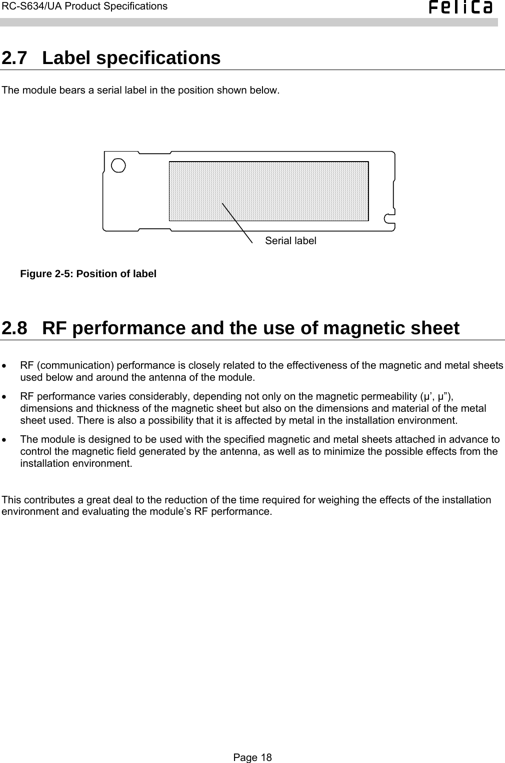
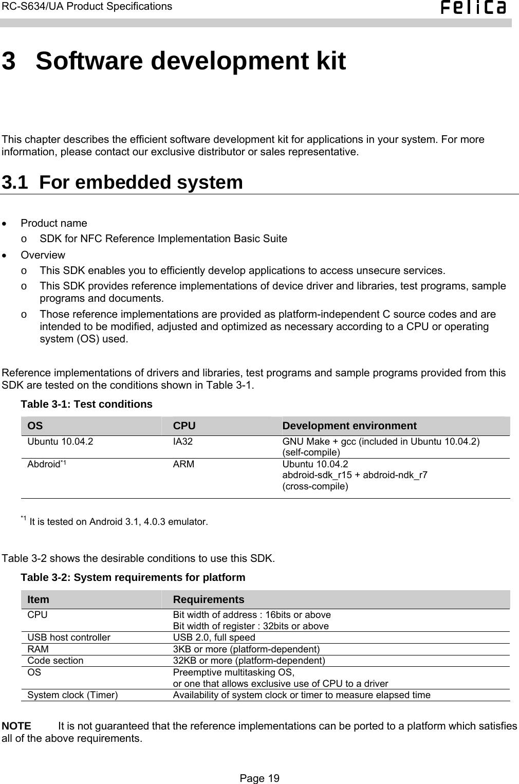
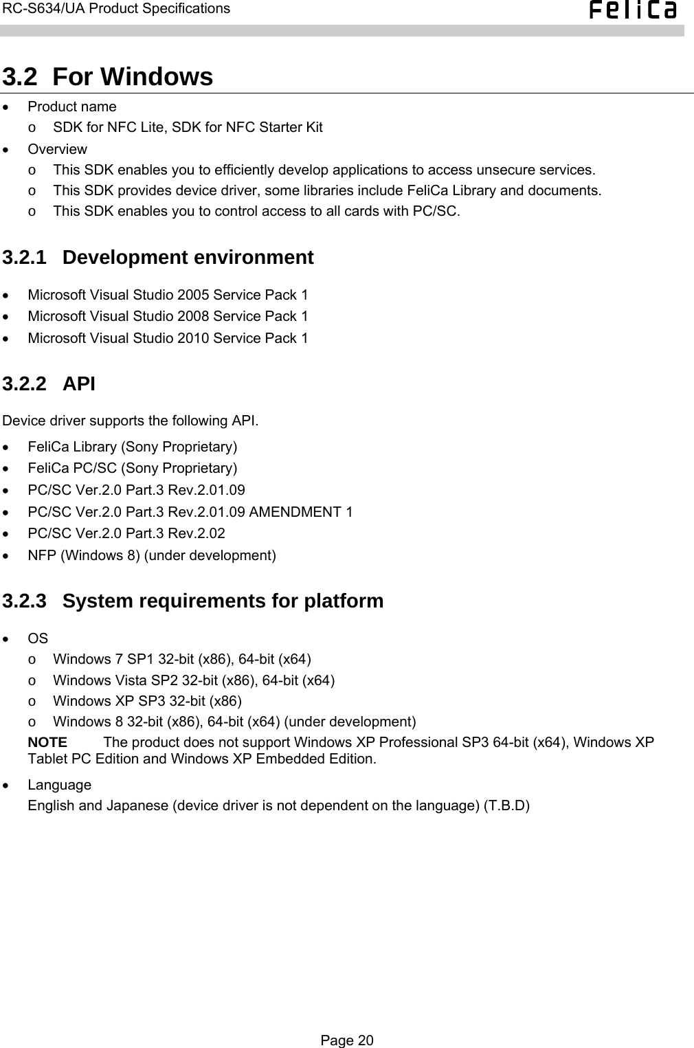
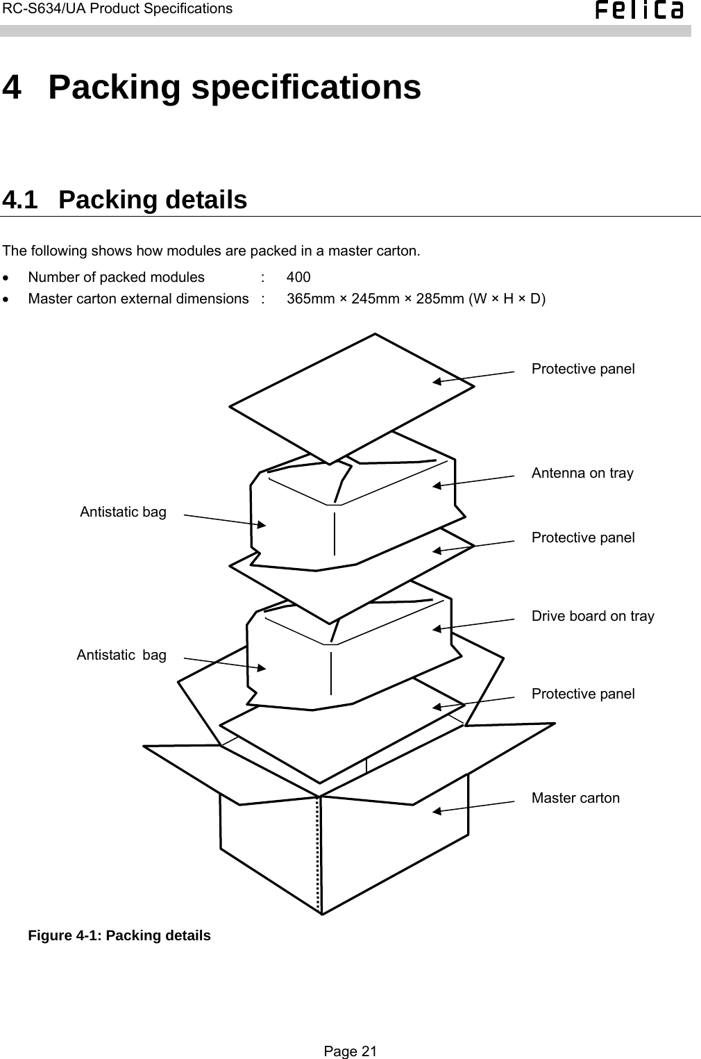
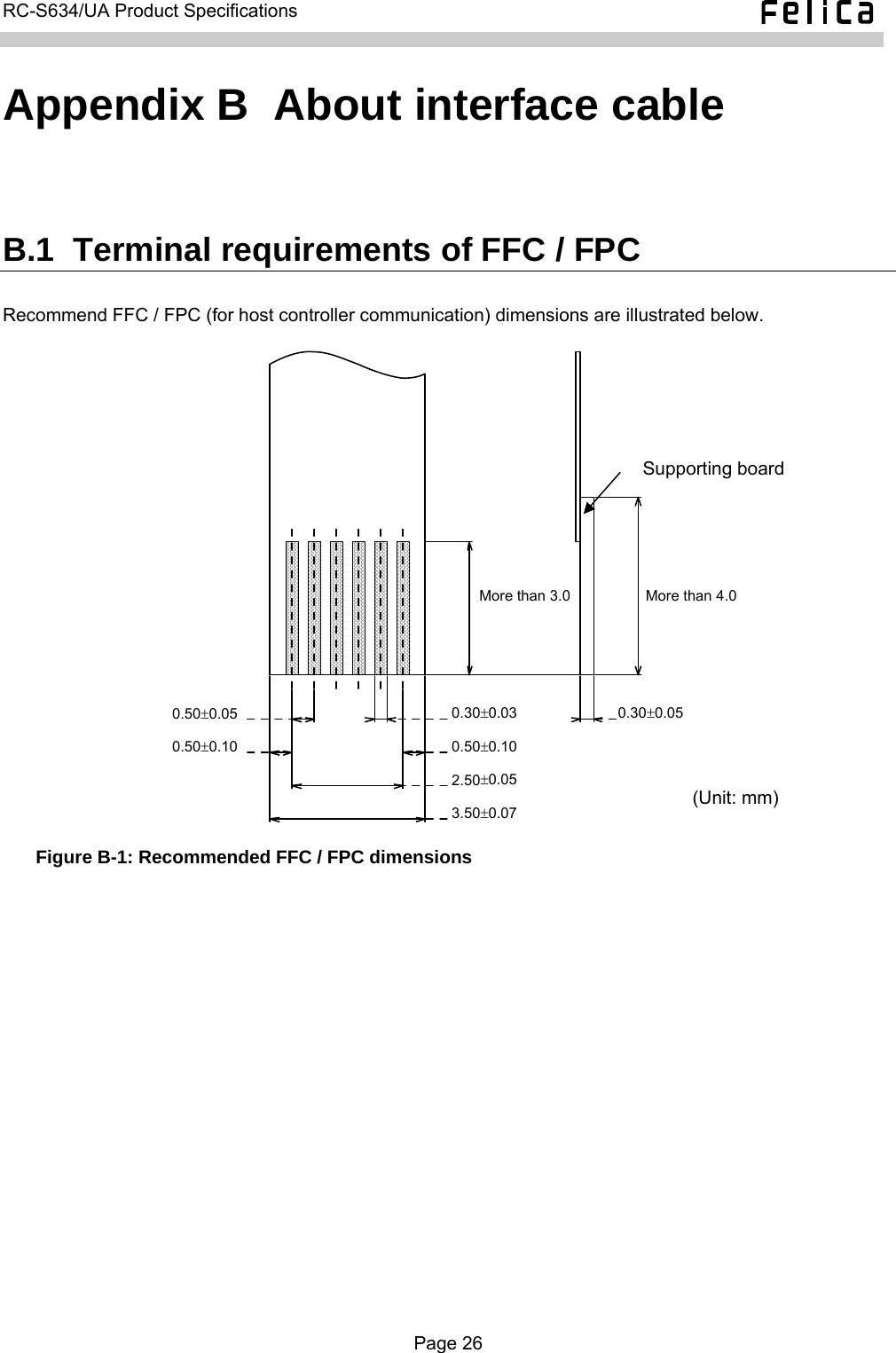
Sony Group RCS634UA Contactless IC Card Reader/Writer User Manual RC S634 UA Product Specifications

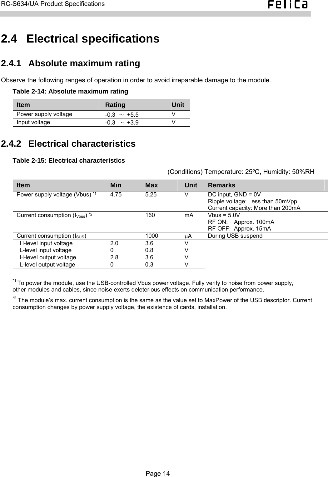
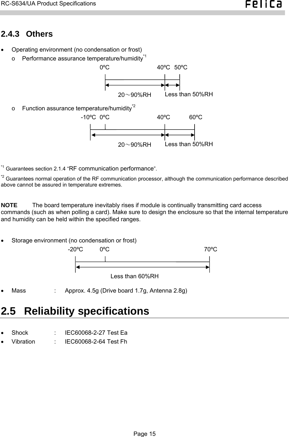
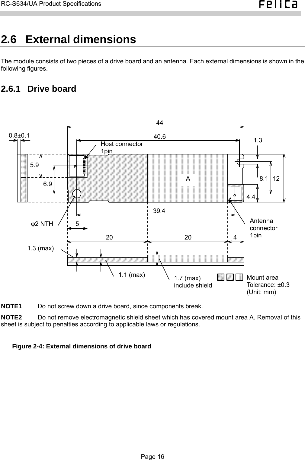
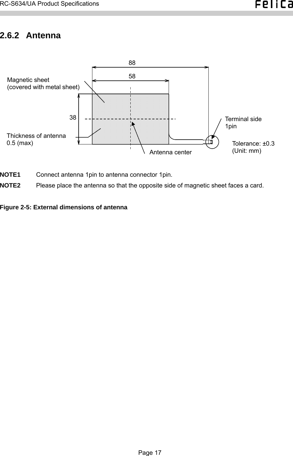
Sony Corporation Contactless IC Card Reader/Writer RC S634 UA Product Specifications

User Manual

     Reader/Writer Module RC-S634/UA Product Specifications   Note: This document is subject to change without notice.
  RC-S634/UA Product Specifications  Introduction This document describes the major features and specifications of Sony’s Reader/Writer module, RC-S634/UA. For the purpose of this document, the terms below denote the products or equipment described to the right. Card  :  A contactless IC card. Reader/Writer  :  A device used to read and write contactless IC cards, tags and devices. Controller  :  An external computer or an equivalent device that is directly connected to a Reader/Writer via a specific cable.  User applications use some libraries to access the RC-S634/UA. API specifications vary depending on the products used, as well as the intended usage of the system, making it necessary to refer to the appropriate document for each. Model name  Description  Usage  Reference document For embedded device  “SDK for NFC Reference Implementation Basic Suite API Specifications” RC-S634/UA  USB for controller interfacing For Windows PC  “SDK for NFC User’s Manual”  NOTE1          A driver for embedded devices, as well as the FeliCa libraries, must be developed by yourself. For this purpose, the “SDK for NFC Reference Implementation Basic Suite” is optionally available. NOTE2          There are three ways to use the RC-S634/UA in combination with Windows PCs. •  Using FeliCa Library which is a part of “SDK for NFC Lite / SDK for NFC Starter Kit” •  Using PC/SC functions •  Using NFP (Near Field Proximity) functions for Windows 8 For system requirement, refer to the following web site: <http://www.sony.net/Products/felica/business/products/list.html> NOTE3     For beginning the services using specific card brands, it is necessary to obtain permission from companies which hold the right to use by yourself. NOTE4     Please note that Business Opportunity Loss by failure or other causes cannot be compensated irrespective of the warranty period. The prior check of operation in your system is strongly recommended.  •  FeliCa is a contactless IC card technology developed by Sony Corporation. •  FeliCa is a trademark of Sony Corporation. •  All names of companies and products contained herein are trademarks or registered trademarks of the respective companies. •  No part of this document may be copied, or reproduced in any form, without the prior consent of Sony Corporation. •  Information in this document is subject to change without notice. •  Sony Corporation assumes no liability for damages arising from, or in connection with, the use of this document.  Page 3
  RC-S634/UA Product Specifications  Safety Information and Caution  WARNING To reduce the risk of fire or electric shock, do not expose this apparatus to rain or moisture. To avoid electrical shock, do not open the cabinet. Refer servicing to qualified personnel only.  For the customers in USA This device complies with Part 15 of the FCC Rules. Operation is subject to the following two conditions: (1) This device may not cause harmful interference, and (2) this device must accept any interference received, including interference that may cause undesired operation.  WARNING You are cautioned that any changes or modifications not expressly approved in this manual could void your authority to operate this equipment.  Note: This equipment has been tested and found to comply with the limits for a Class B digital device, pursuant to Part 15 of the FCC Rules. These limits are designed to provide reasonable protection against harmful interference in a residential installation. This equipment generates, uses, and can radiate radio frequency energy and, if not installed and used in accordance with the instructions, may cause harmful interference to radio communications. However, there is no guarantee that interference will not occur in a particular installation. If this equipment does cause harmful interference to radio or television reception, which can be determined by turning the equipment off and on, the user is encouraged to try to correct the interference by one or more of the following measures: -Reorient or relocate the receiving antenna. -Increase the separation between the equipment and receiver. -Connect the equipment into an outlet on a circuit different from that to which the receiver is connected. -Consult the dealer or an experienced radio/TV technician for help.  Page 4
  RC-S634/UA Product Specifications  For the customers in Canada This Class B digital apparatus complies with Canadian ICES-003.  This device complies with Industry Canada licence-exempt RSS standard(s). Operation is subject to the following two conditions: (1) this device may not cause interference, and (2) this device must accept any interference, including interference that may cause undesired operation of the device.  The term “IC:” before the radio certification number only signifies that Industry Canada technical specifications were met.  Pour les clients au Canada Cet appareil numérique de la classe B est conforme à la norme NMB-003 du Canada.  Le présent appareil est conforme aux CNR d'Industrie Canada applicables aux appareils radio exempts de licence. L’utilisation doit répondre aux deux conditions suivantes: (1) ce matériel ne doit pas provoquer de brouillage et (2) il doit accepter tout brouillage, même celui qui est susceptible d’affecter son fonctionnement.  La mention « IC: » devant le numéro de certification/ homologation signifie uniquement que les spécifications techniques d’Industrie Canada sont remplies.   For the customers in Europe Hereby, Sony Corporation, declares that this RC-S634/UA is in compliance with the essential requirements and other relevant provisions of Directive 1999/5/EC. For details, please access the following URL: http://www.compliance.sony.de/    For use in following areas: residential, commercial and light industrial.  This product has been tested and found compliant with the limits set out in the EMC Directive for using connection cables not longer than 3 meters (9.8 feet).  Emissions from this inductive device could cause interference to nearby receivers of other radio services.  The manufacturer of this product is Sony Corporation, 1-7-1 Konan, Minato-ku, Tokyo, Japan The Authorized Representative for EMC and product safety is Sony Deutschland GmbH, Hedelfinger Strasse 61, 70327 Stuttgart, Germany Page 5
  RC-S634/UA Product Specifications   Contents 1 Key functions and features......................................................................................................... 8 2 Hardware specifications.............................................................................................................. 9 2.1 Major specifications............................................................................................................................... 9 2.1.1 FeliCa or ISO/IEC 18092 (212 / 424 kbps) communication ........................................................ 9 2.1.2 ISO/IEC 14443 or ISO/IEC 18092 (106 kbps) communication.................................................... 9 2.1.3 Compatible cards, tags and devices*1,*2 .................................................................................... 10 2.1.4 RF communication performance ............................................................................................... 10 2.2 Interface .............................................................................................................................................. 11 2.2.1 Connector .................................................................................................................................. 11 2.2.2 Pin assignment .......................................................................................................................... 11 2.3 USB communication specifications..................................................................................................... 12 2.4 Electrical specifications ....................................................................................................................... 14 2.4.1 Absolute maximum rating.......................................................................................................... 14 2.4.2 Electrical characteristics............................................................................................................ 14 2.4.3 Others........................................................................................................................................ 15 2.5 Reliability specifications ...................................................................................................................... 15 2.6 External dimensions............................................................................................................................ 16 2.6.1 Drive board ................................................................................................................................16 2.6.2 Antenna ..................................................................................................................................... 17 2.7 Label specifications............................................................................................................................. 18 2.8 RF performance and the use of magnetic sheet................................................................................. 18 3 Software development kit ......................................................................................................... 19 3.1 For embedded system ........................................................................................................................ 19 3.2 For Windows ....................................................................................................................................... 20 3.2.1 Development environment......................................................................................................... 20 3.2.2 API ............................................................................................................................................. 20 3.2.3 System requirements for platform ............................................................................................. 20 4 Packing specifications .............................................................................................................. 21 4.1 Packing details (tentative)................................................................................................................... 21 5 Precautions ................................................................................................................................22 5.1 Handling precautions .......................................................................................................................... 22 5.2 Notes on external appearance............................................................................................................ 23 Appendix A About installation..................................................................................................... 24 A.1 Installation requirements for RC-S634/UA ......................................................................................... 24 A.2 Reduction of the impact of metal ........................................................................................................ 25 Appendix B About interface cable .............................................................................................. 26 B.1 Terminal requirements of FFC / FPC ................................................................................................. 26   Page 6
  RC-S634/UA Product Specifications   (Blank page) Page 7
  RC-S634/UA Product Specifications  1  Key functions and features RC-S634/UA (hereinafter called the module) writes and reads data to and from FeliCa-enabled contactless IC cards. It can also write and read data based on the ISO/IEC 14443 contactless IC card standards. Immune to wear caused by dirt and friction, contactless operation leads to enhanced maintainability. Device driver for the module supports the industry-standard PC/SC specifications version 2.0 for the programming interfaces between PC applications, the operating system and cards. Key functions and features of the module are detailed below. For more information, please contact our exclusive distributor or sales representative.  •  Based on an inductive read/write system type-certified by the Radio Law of Japan. It is also compliant with the relevant standards in the United States, Canada, and Europe.  •  Compatible with a wide variety of not only cards based on ISO/IEC14443-4 (T=CL) such as MIFARE DESFire, Calypso CD Light, but also MIFARE DESFire EV1, MIFARE Plus, Topaz / Jewel, NFC Forum Tags and NFC-Forum-certified devices.  •  Compactly designed with a really thin antenna.  •  Interface versatility made possible by the use of USB for host controller connection.  •  Environmentally friendly, with the adoption of lead-free soldering.  •  Successful passage of rigorous validation tests by Microsoft’s WHQL (Windows Hardware Quality Labs).  •  Higher interoperability provided by the NFC Forum 1st Wave Certification with other NFC-Forum-certified devices  •  An effective development environment “SDK for NFC & Adobe AIR / Adobe Flash” is available.  Page 8
  RC-S634/UA Product Specifications  2  Hardware specifications This chapter focuses on major hardware specifications. 2.1  Major specifications The following describes the module’s major specifications. 2.1.1  FeliCa or ISO/IEC 18092 (212 / 424 kbps) communication •  Carrier frequency (fc)  :  13.56 MHz •  Data transfer rate*1  :  fc/64 (212 kbps, approximately), fc/32 (424 kbps, approximately) • Modulation system  :  Transmission – ASK, Reception – ASK •  Bit coding  :  Transmission – Manchester coding, Reception – Manchester coding •  Communication system  :  Half-duplex communication  *1 Available only when the card or the device to be used is also compatible with fc/32. <Ad-hoc communication> Feasibility of data exchange and other functions necessary for application execution depends on the FeliCa Ad-hoc Link Protocol (FALP) on the device used to control the module and mobile phones, as well as the method of implementing the FALP-compatible application. For more information, please refer to the documents that accompany Sony’s software development kit and individual applications (there is no description about FALP in an English version). 2.1.2  ISO/IEC 14443 or ISO/IEC 18092 (106 kbps) communication •  Carrier frequency (fc)  :  13.56 MHz •  Data transfer rate*2  :  fc/128 (106 kbps, approximately), fc/64 (212 kbps, approximately),       fc/32 (424 kbps, approximately) • Modulation system o  Type A (fc/128)  :  Transmission – ASK, Reception – ASK o  Type A (fc/64, fc/32)  :  Transmission – ASK, Reception – BPSK o  Type B  :  Transmission – ASK, Reception – BPSK • Bit coding o  Type A (fc/128)  :  Transmission – Modified Miller      Reception – Manchester coding with subcarrier o  Type A (fc/64, fc/32)  :  Transmission – Modified Miller,  Reception – NRZ with subcarrier o  Type B  :  Transmission – NRZ, Reception – NRZ with subcarrier •  Communication system  :  Half-duplex communication  **2 Available only when the card or the device to be used is also compatible with fc/64 or fc/32.  Page 9
  RC-S634/UA Product Specifications  2.1.3  Compatible cards, tags and devices*1,*2 •  Card based on FeliCa o  RC-S850 Series (RC-S850, RC-S853, RC-S854, RC-S855) o  RC-S860 Series (RC-S860, RC-S862, RC-S864) o  RC-S880 Series (RC-S888, RC-S889) o  FeliCa Lite (RC-S886, RC-S710) o  FeliCa Plug / NFC Dynamic Tag (RC-S801, RC-S802) o  Mobile phone incorporating a Mobile FeliCa IC chip (on which the Mobile FeliCa OS Version 2.0 is running) •  Card based on ISO/IEC14443-4 (T=CL) o MIFARE DESFire  o Calypso CD Light •  Topaz / Jewel • MIFARE Classic •  MIFARE Ultralight / Ultralight C •  MIFARE DESFire / DESFire EV1 • MIFARE Plus  • PicoPass (ISO/IEC14443-2) •  NFC Forum Tag o  Type 1 static / dynamic o  Type 2 static / dynamic o Type 3 o  Type 4A / 4B • NFC-Forum-certified device  *1 Usable number of cards: One at a time. *2 Please consult us in advance when using a card or a device other than the ones listed above.   2.1.4  RF communication performance •  25 mm or more (No dead zones of more than 1 mm wide within the above range) <Measurement conditions> In a free space (temperature: 25ºC, humidity: 50%RH) that is potentially unaffected by nearby radio waves and magnetic sources, a single RC-S888 card (operating at its center frequency) is polled by a standard module. The card is placed so that its center aligns with the center of the module’s antenna along a vertical axis perpendicular to the antenna surface, with its longitudinal edges maintained in parallel to those of the antenna.  NOTE          The communication performance may be different with the kind of the card, making it necessary to verify its performance.  Page 10
  RC-S634/UA Product Specifications  2.2  Interface Interfacing between the module and the controller utilizes the connector described below. 2.2.1  Connector •  Model number: 9690S-06B-GFN1 made by IRISO ELECTRONICS CO., LTD. Low-profile, 0.5 mm pitch FFC/FPC connector   (Au plated / Double terminal / SMT / Right angle / NON-ZIF / 6 poles)  NOTE1          Please make sure to connect a cable in the right direction because the connector has a double terminal. NOTE2          For applicable cable, refer to B.1 “Terminal requirements of FFC / FPC”. 2.2.2  Pin assignment Table 2-1: Pin assignment No.  Designation  Function  Remarks 1  Vbus  Power supply  DC5.0V input 2  D-  D- signal  USB 2.0, full speed 3  D+  D+ signal  USB 2.0, full speed 4 GND  Ground  For grounding 5  Reserve  Non  Requires OPEN processing by the controller 6  Reserve  Non  Requires OPEN processing by the controller  NOTE          Please confirm the position of 1pin in external dimensions.  Page 11
  RC-S634/UA Product Specifications  2.3  USB communication specifications A suspend signal from the controller is received through the USB interface to offer the capability for reduced power consumption. See the tables below for USB communication specifications. Table 2-4: Communication specifications Item  Description USB transfer speed  USB 2.0, full speed Number of endpoints  4 Endpoint 0  Control transfer using individual 64-byte buffers for IN and OUT directions Endpoint 1  Bulk transfer using individual 64-byte buffers for IN direction Endpoint 2  Bulk transfer using individual 64-byte buffers for OUT direction Command transfer  Data of any given packet length is bulk-transferred to Endpoint 2 (OUT direction). Response transfer  Data of any given packet length is bulk-transferred from Endpoint 1 (IN direction).  Table 2-5: Device descriptor bLength 12h bDescriptorType 01h bcdUSB 0200h bDeviceClass FFh bDeviceSubClass 00h bDeviceProtocol 00h bMaxPacketSize0 40h idVendor 054Ch idProduct 06C2h bcdDevice 0111h iManufacturer 01h iProduct 02h iSerialNumber 04h bNumConfigurations 01h  Table 2-6: Configuration descriptor bLength 09h bDescriptorType 02h wTotalLength 0020h bNumInterfaces 01h bConfigurationValue 01h iConfiguration 00h bmAttributes 80h MaxPower 50h  Table 2-7: Interface descriptor bLength 09h bDescriptorType 04h bInterfaceNumber 00h bAlternateSetting 00h bNumEndpoints 02h bInterfaceClass FFh bInterfaceSubClass 00h bInterfaceProtocol 00h iInterface 00h   Page 12
  RC-S634/UA Product Specifications  Table 2-8: Endpoint descriptor (OUT) bLength 07h bDescriptorType 05h bEndpointAddress 02h bmAttributes 02h wMaxPacketSize 0040h bInterval 00h  Table 2-9: Endpoint descriptor (IN) bLength 07h bDescriptorType 05h bEndpointAddress 81h bmAttributes 02h wMaxPacketSize 0040h bInterval 00h  Table 2-10: String descriptor #0 bLength 04h bDescriptorType 03h wLANGID 0409h  Table 2-11: String descriptor #1 bLength 0Ah bDescriptorType 03h bString SONY (Unicode)  Table 2-12: String descriptor #2 bLength 16h bDescriptorType 03h bString RC-S634/UA (Unicode)  Table 2-13: String descriptor #4 bLength 10h bDescriptorType 03h bString  “Serial number” (e.g. 0000001) (Unicode)   Page 13
  RC-S634/UA Product Specifications  2.4  Electrical specifications 2.4.1  Absolute maximum rating Observe the following ranges of operation in order to avoid irreparable damage to the module. Table 2-14: Absolute maximum rating Item  Rating  Unit Power supply voltage  -0.3  ~ +5.5  V Input voltage  -0.3  ~ +3.9  V 2.4.2  Electrical characteristics Table 2-15: Electrical characteristics (Conditions) Temperature: 25ºC, Humidity: 50%RH Item  Min  Max  Unit  Remarks Power supply voltage (Vbus) *1  4.75  5.25  V  DC input, GND = 0V Ripple voltage: Less than 50mVpp Current capacity: More than 200mA Current consumption (IVbus) *2    160  mA  Vbus = 5.0V RF ON:  Approx. 100mA RF OFF:  Approx. 15mA Current consumption (ISUS)   1000  μA  During USB suspend   H-level input voltage  2.0  3.6  V     L-level input voltage  0  0.8  V     H-level output voltage  2.8  3.6  V     L-level output voltage  0  0.3  V    *1 To power the module, use the USB-controlled Vbus power voltage. Fully verify to noise from power supply, other modules and cables, since noise exerts deleterious effects on communication performance. *2 The module’s max. current consumption is the same as the value set to MaxPower of the USB descriptor. Current consumption changes by power supply voltage, the existence of cards, installation.  Page 14
  RC-S634/UA Product Specifications  2.4.3  Others •  Operating environment (no condensation or frost) o Performance assurance temperature/humidity*1 0ºC 50ºC20~90%RH  Less than 50%RH 40ºC o  Function assurance temperature/humidity*2 20~90%RH 0ºC 60ºCLess than 50%RH 40ºC-10ºC   *1 Guarantees section 2.1.4 “RF communication performance”. *2 Guarantees normal operation of the RF communication processor, although the communication performance described above cannot be assured in temperature extremes.  NOTE     The board temperature inevitably rises if module is continually transmitting card access commands (such as when polling a card). Make sure to design the enclosure so that the internal temperature and humidity can be held within the specified ranges.  •  Storage environment (no condensation or frost) 0ºC 70ºCLess than 60%RH -20ºC  •  Mass      :  Approx. 4.5g (Drive board 1.7g, Antenna 2.8g) 2.5  Reliability specifications •  Shock      :  IEC60068-2-27 Test Ea •  Vibration    :  IEC60068-2-64 Test Fh  Page 15
  RC-S634/UA Product Specifications  2.6  External dimensions The module consists of two pieces of a drive board and an antenna. Each external dimensions is shown in the following figures. 2.6.1  Drive board  1.1 (max) 1.7 (max) include shield1.3 (max) 445.9 1.3 40.60.8±0.1 39.45 20 20 4 6.9  8.1 4.4 A Host connectorAntenna connector1pin φ2 NTH 121pin Mount area Tolerance: ±0.3(Unit: mm)   NOTE1     Do not screw down a drive board, since components break. NOTE2          Do not remove electromagnetic shield sheet which has covered mount area A. Removal of this sheet is subject to penalties according to applicable laws or regulations.  Figure 2-4: External dimensions of drive board  Page 16
  RC-S634/UA Product Specifications  2.6.2  Antenna  Magnetic sheet (covered with metal sheet) Terminal side 1pin Antenna center883858Tolerance: ±0.3 (Unit: mm) Thickness of antenna 0.5 (max)   NOTE1     Connect antenna 1pin to antenna connector 1pin. NOTE2     Please place the antenna so that the opposite side of magnetic sheet faces a card.  Figure 2-5: External dimensions of antenna  Page 17
  RC-S634/UA Product Specifications  2.7  Label specifications The module bears a serial label in the position shown below.  Serial label  Figure 2-5: Position of label  2.8  RF performance and the use of magnetic sheet •  RF (communication) performance is closely related to the effectiveness of the magnetic and metal sheets used below and around the antenna of the module. •  RF performance varies considerably, depending not only on the magnetic permeability (μ’, μ”), dimensions and thickness of the magnetic sheet but also on the dimensions and material of the metal sheet used. There is also a possibility that it is affected by metal in the installation environment. •  The module is designed to be used with the specified magnetic and metal sheets attached in advance to control the magnetic field generated by the antenna, as well as to minimize the possible effects from the installation environment.  This contributes a great deal to the reduction of the time required for weighing the effects of the installation environment and evaluating the module’s RF performance.  Page 18
  RC-S634/UA Product Specifications  3  Software development kit This chapter describes the efficient software development kit for applications in your system. For more information, please contact our exclusive distributor or sales representative. 3.1  For embedded system  • Product name o  SDK for NFC Reference Implementation Basic Suite • Overview  o  This SDK enables you to efficiently develop applications to access unsecure services. o  This SDK provides reference implementations of device driver and libraries, test programs, sample programs and documents. o  Those reference implementations are provided as platform-independent C source codes and are intended to be modified, adjusted and optimized as necessary according to a CPU or operating system (OS) used.  Reference implementations of drivers and libraries, test programs and sample programs provided from this SDK are tested on the conditions shown in Table 3-1. Table 3-1: Test conditions OS  CPU  Development environment Ubuntu 10.04.2  IA32  GNU Make + gcc (included in Ubuntu 10.04.2) (self-compile) Abdroid*1 ARM Ubuntu 10.04.2 abdroid-sdk_r15 + abdroid-ndk_r7 (cross-compile)  *1 It is tested on Android 3.1, 4.0.3 emulator.  Table 3-2 shows the desirable conditions to use this SDK. Table 3-2: System requirements for platform Item  Requirements CPU    Bit width of address : 16bits or above Bit width of register : 32bits or above USB host controller  USB 2.0, full speed RAM  3KB or more (platform-dependent) Code section  32KB or more (platform-dependent) OS  Preemptive multitasking OS, or one that allows exclusive use of CPU to a driver System clock (Timer)  Availability of system clock or timer to measure elapsed time  NOTE     It is not guaranteed that the reference implementations can be ported to a platform which satisfies all of the above requirements.  Page 19
  RC-S634/UA Product Specifications  3.2  For Windows • Product name o  SDK for NFC Lite, SDK for NFC Starter Kit • Overview  o  This SDK enables you to efficiently develop applications to access unsecure services. o  This SDK provides device driver, some libraries include FeliCa Library and documents. o  This SDK enables you to control access to all cards with PC/SC. 3.2.1  Development environment •  Microsoft Visual Studio 2005 Service Pack 1 •  Microsoft Visual Studio 2008 Service Pack 1 •  Microsoft Visual Studio 2010 Service Pack 1 3.2.2  API Device driver supports the following API. •  FeliCa Library (Sony Proprietary) •  FeliCa PC/SC (Sony Proprietary) •  PC/SC Ver.2.0 Part.3 Rev.2.01.09 •  PC/SC Ver.2.0 Part.3 Rev.2.01.09 AMENDMENT 1 •  PC/SC Ver.2.0 Part.3 Rev.2.02 •  NFP (Windows 8) (under development) 3.2.3  System requirements for platform • OS  o  Windows 7 SP1 32-bit (x86), 64-bit (x64) o  Windows Vista SP2 32-bit (x86), 64-bit (x64) o  Windows XP SP3 32-bit (x86) o  Windows 8 32-bit (x86), 64-bit (x64) (under development) NOTE     The product does not support Windows XP Professional SP3 64-bit (x64), Windows XP Tablet PC Edition and Windows XP Embedded Edition. • Language English and Japanese (device driver is not dependent on the language) (T.B.D)  Page 20
  RC-S634/UA Product Specifications  4  Packing specifications 4.1  Packing details The following shows how modules are packed in a master carton. •  Number of packed modules     :  400 •  Master carton external dimensions  :  365mm × 245mm × 285mm (W × H × D)  Drive board on trayAntenna on tray Protective panel Antistatic bag Master carton Antistatic bag Protective panel Protective panel  Figure 4-1: Packing details  Page 21
  RC-S634/UA Product Specifications  5  Precautions 5.1  Handling precautions The module must be handled with special care, keeping the following precautions in mind. •  The module is an inductive-type read/write communication device that is type-certified in compliance with the Radio Law of Japan. The operating frequency is 13.56 MHz. Disassembly or modification of the module, removal of the type number or similar acts are subject to penalties according to applicable laws. •  Be sure to use a stable power supply so that the module can be protected from the effect of noise and excessive voltage peaks, such as lightning, transmitted through the power supply connector. •  Do not cause any chemical or physical damage to the module. •  Do not subject the module surface to contaminated air or materials. •  Tightly ground not only module after installation but all jigs, machines, workbenches and workers’ bodies to prevent static electricity from affecting the module. •  For safety’s sake, be sure to wear gloves when handling the module, although its surfaces are carefully finished. •  Protect the module from interference from other wireless machines. •  Do not install the module in an environment where a strong electromagnetic field may exert deleterious effects on communication performance. Take special note of the installation location so that interference between the module and other equipment can be adequately controlled. •  Communication performance may be affected by the harmonics of the 13.56 MHz carrier frequency generated on the signal line. •  Check in advance the compatibility between the module and your system. The module cannot handle part of the processing sequences*1 provided by mobile phones and other portable devices incorporating mobile FeliCa IC chips. •  The interface cable (FFC / FPC) is not supplied, making it necessary to prepare the one appropriate for your system. When selecting the cable, make sure to connect a cable in the right direction because the connector has a double terminal. •  Do not flourish or do not pull strongly the antenna which is connected with a drive board, since the antenna terminal may break. •  Measures for static noise and power line noise must be designed and incorporated on your own. Especially, if the module is connected to two or more system ground ports which have a difference in electric potential, it may depreciate communication performance and cause unexpected noise.  *1 Among the processing sequences unique to mobile FeliCa compatible portable devices, the module cannot handle the sequence which allows wireless communication from the Reader/Writer after the mobile FeliCa IC chip was activated by the portable device via a wired interface. For more information, refer to the “Mobile FeliCa Technical Information” (Japanese only) that explains Reader/Writer operation in mobile applications.  Page 22
  RC-S634/UA Product Specifications  5.2  Notes on external appearance Since the module is designed for embedded applications, please realize that flaws on the order described below may occur. •  Scratch or stain on the product surface, which has no effect on performance. •  Change in the board color.  Page 23
  RC-S634/UA Product Specifications  Appendix A  About installation A.1  Installation requirements for RC-S634/UA The following describes the points to remember when installing the modules. 1.  Do not use any metal or carbon compound as the material for the cabinet. The cabinet surface must be at least 1.5mm apart from the board surface. 2.  Stick the antenna to a plane (extreme modification of the antenna is subject to penalties according to applicable laws or regulations). Do not place any metal in the forbidden area (dot-meshed area in Figure A-1) secured around the antenna. Particularly, communication performance undoubtedly deteriorates if a plate-like metal is put near the antenna. 3.  In order not to induce eddy current, make a cut in the metal plate surrounding the above forbidden zone. 4.  If no performance improvement is achieved through the steps described above, add magnetic sheets, as shown in Figure A-2, to the metal surface that faces the card.  Side view Bottom view Metal forbidden area more than 20mm more than 20mm more than 20mm more than 1.5mm Antenna area  Card direction Card Do not place a metal plate below metal forbidden zoneas much as possible. 3mm more than IC more than 30mm When an antenna unit is surrounded with a metal plate,make sure to make a cut. Cabinet Antenna  Figure A-1: Installation requirements  Page 24
  RC-S634/UA Product Specifications  A.2  Reduction of the impact of metal Deviation from the resonance point caused by bringing the card closer to the metal plate may result in a change in the card’s original characteristics. The effect of metal plate could be reduced by adding magnetic sheets to the positions illustrated above.   Cabinet Magnetic sheet Addition of magnetic sheetUnavoidable metal in the cabinet Card Antenna Figure A-2: Reduction of the impact of metal    Page 25
  RC-S634/UA Product Specifications  Appendix B  About interface cable B.1  Terminal requirements of FFC / FPC Recommend FFC / FPC (for host controller communication) dimensions are illustrated below. (Unit: mm) Supporting board 3.50±0.07 More than 3.0 More than 4.0 0.30±0.05 0.30±0.03 0.50±0.10 2.50±0.05 0.50±0.050.50±0.10 Figure B-1: Recommended FFC / FPC dimensions   Page 26
  Page 27   RC-S634/UA Product Specifications   (Blank page)
  Reader/Writer Module RC-S634/UA Product Specifications    July 2012  FeliCa Business Division  Sony Corporation  © 2012 Sony Corporation  Printed in Japan

Navigation menu