Sony Group RM215 RF Remote Module User Manual
Sony Corporation RF Remote Module
Contents
- 1. Users Manual
- 2. Manual
- 3. User manual
- 4. User Manual
Users Manual
Digital Wireless
Transmitter
3-873-945-11 (1)
Operating Instructions
DWT-B01
©2008 Sony Corporation
The supplied CD-ROM includes the Operating Instructions for the DWT-B01
digital wireless transmitter (English, French, German, Italian, and Spanish
versions). For more details, see “Using the CD-ROM manual” on page 11.

2
WARNING
Batteries shall not be exposed to excessive
heat such as sunshine, fire or the like.
You are cautioned that any changes or
modifications not expressly approved in
this manual could void your authority to
operate this equipment.
For the customers in the U.S.A.
This device complies with part 15 of the
FCC Rules. Operation is subject to the
following two conditions: (1) this device
may not cause harmful interference, and (2)
this device must accept any interference
received, including interference that may
cause undesired operation.
Important Notice
This equipment complies with FCC
radiation exposure limits set forth for an
uncontrolled environment. This equipment
should be installed and operated with
minimum distance 20cm between the
radiator and body (excluding extremities:
hands, wrists and feet).
Notice for customers in the
U.S.A.
Use of Sony wireless devices is regulated
by the Federal Communications
Commision as described in Part 74 subpart
H of the FCC regulations and users
authorized thereby are required to obtain an
appropriate license.
IMPORTANT NOTE: To comply with the
FCC RF exposure compliance
requirements, no change to the antenna or
the device is permitted,
Any change to the antenna or the device
could result in the device exceeding the RF
exposure requirements and void user’s
authority to operate this device.
This device complies with FCC radiation
exposure limits set forth for uncontrolled
equipment and meets the FCC radio
frequency (RF) Exposure Guidelines in
Supplement C to OET65. This device has
very low levels of RF energy that it is
deemed to comply without testing of
specific absorption radio (SAR).
For the customers in Canada
Operation is subject to the following two
conditions: (1) this device may not cause
interference, and (2) this device must accept
any interference, including interference that
may cause undesired operation of the
device.
The term “IC” before the radio certification
number only signifies that Industry Canada
technical specifications were met.
To reduce potential radio interference to
other users, the antenna type and its gain
should be so chosen that the equivalent
isotropically radiated power (EIRP) is not
more than that required for successful
communication.
This device has been designed to operate
with an antenna having a maximum gain of
0 dB.
Antenna having a higher gain is strictly
prohibited per regulations of Industry
Canada.
The required antenna impedance is 50
ohms.
Notice for customers in Canada:
Use of Sony wireless devices is regulated
by the Industry Canada as described in their
Radio Standard Specification RSS-123.
A licence is normally required. The local
district office of Industry Canada should
therefore be contacted. When the operation
of the device is within the broadcast band,
the licence is issued on no-interference,
noprotection basis with respect to broadcast
signals.
AVERTISSEMENT
N’exposez pas les batteries à une chaleur
excessive, au soleil ou près d’un feu par
exemple.

3
Pour les utilisateurs au Canada
L’utilisation doit répondre aux deux
conditions suivantes : (1) ce matériel ne doit
pas provoquer de brouillage et (2) il doit
accepter tout brouillage, même celui qui est
susceptible d’affecter son fonctionnement.
La mention « IC: » devant le numéro de
certification/ homologation signifie
uniquement que les spécifications
techniques d’Industrie Canada sont
remplies.
R-13_FRXXXTo reduce potential radio
interference to other users, the antenna type
and its gain should be so chosen that the
equivalent isotropically radiated power
(EIRP) is not more than that required for
successful communication.XXX
R-14_FRXXXThis device has been
designed to operate with an antenna having
a maximum gain of 0 dB.
Antenna having a higher gain is strictly
prohibited per regulations of Industry
Canada.
The required antenna impedance is 50
ohms.XXX
Remarque à l’intention des
utilisateurs au Canada:
L’usage des appareils sans fil Sony est
réglementé par l’Industrie Canada comme
décrit dans leur Cahier des Normes
Radioélectriques CNR-123.
Une licence est normalement requise.
Le bureau de l’Industrie Canada doit être
contacté. Lorsque le fonctionnement de
l’appareil respecte les limites de la bande de
radiodiffusion, la licence est accordée sur la
base d’une non-interférence, non-
protection pour les signaux de
radiodiffusion.
WARNUNG
Akkus dürfen keinesfalls übermäßiger
Wärmeeinwirkung ausgesetzt werden, wie
z.B. Sonneneinstrahlung, Feuer o. ä.
AVVERTENZA
Le batterie non devono essere esposte a
fonti di calore eccessivo come luce solare
diretta, fuoco, ecc.
ADVERTENCIA
No se deben exponer las baterÌas a una
fuente de calor excesivo como la luz del sol,
el fuego o similar.
For the customers in Europe
Hereby, Sony Corporation, declares that
this DWT-B01 is in compliance with the
essential requirements and other relevant
provisions of the Directive 1999/5/EC.
For details, please access the following
URL: http://www.compliance.sony.de/
This product is intended to be used in the
following countries : United Kingdom,
Germany, Norway, Luxembourg, Belgium,
Denmark, France, Italy, Sweden,
Switzerland, Finland, Iceland, and Turkey.
Note for the users in Spain
Carrier frequencies only allowed 2421,
2449, 2477MHz in Spain.
Pour les clients en Europe
Par la présente Sony Corporation déclare
que l'appareil DWT-B01 est conforme aux
U.K. 470 - 862 MHz
Germany 470 - 606 MHz, 614 -
862 MHz
Norway 800 - 820 MHz
Luxembourg 470 - 862 MHz
Belgium 470 - 862 MHz
Denmark 800.100 - 819.900 MHz
France 470 - 830 MHz
Italy 470 - 854 MHz
Sweden 470 - 862 MHz
Switzerland 790 - 862 MHz
Finland 790.100 - 821.900 MHz,
854 - 862 MHz
Iceland 470 - 862 MHz
Turkey 470 - 862 MHz

11
Using the CD-ROM manual
Using the CD-
ROM manual
The supplied CD-ROM includes Operating
Instructions for the DWT-B01 (English,
French, German, Italian, and Spanish
versions) and the frequency lists (English
and Japanese versions).
Preparations
The following program must be installed on
your computer in order to read the
Operating Instructions contained on the
CD-ROM.
• Adobe Reader Version 6.0 or higher
If Adobe Reader is not installed, you can
download it from the following URL:
http://www.adobe.com/
Adobe and Adobe Reader are trademarks of
Adobe Systems Incorporated in the United States
and/or other countries.
Reading the CD-ROM
manual
To read the operation manuals contained on
the CD-ROM, do the following.
1Insert the CD-ROM in your CD-ROM
drive.
A cover page appears automatically in
your browser.
If it does not appear automatically in
the browser, double-click on the
index.htm file on the CD-ROM.
2Select and click on the Operating
Instructions that you want to read.
This opens the PDF file of the
operation manuals.
The files may not be displayed properly,
depending on the version of Acrobat
Reader. In such a case, install the latest
version you can download from the URL
mentioned in “Preparations” above.
If you have lost or damaged the CD-ROM,
you can purchase a new one to replace it.
Contact your Sony service representative.
Reading the Sony Digital
Wireless Microphone
System Frequency Lists
The frequency lists for US and European
models are contained on the CD-ROM. To
read the frequency lists, do the following:
1Insert the CD-ROM in your CD-ROM
drive.
A cover page appears automatically in
your browser.
2Select and click on the frequency list
that you want to read.
This opens the PDF file of the
frequency list.
Note
12 Parts identification
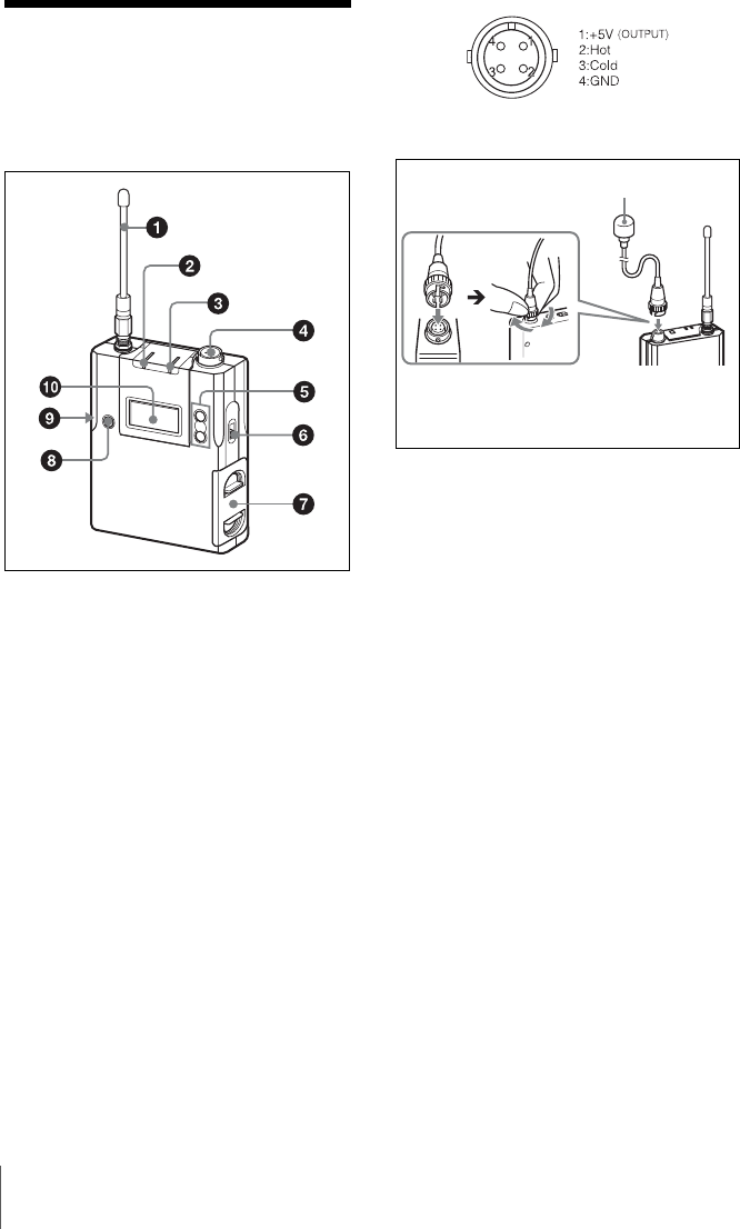
Parts
identification
aAntenna
b AF (audio input level) /PEAK
indicator
Lights up green when the signal input is
stronger than the reference level.
Lights up red when the signal input is 3 dB
below the level at which distortion begins.
cPOWER indicator
Lights up green when the transmitter is
turned on. When the battery is exhausted,
the indicator starts flashing.
dAudio input connector (SMC9-4S)
Connects the output plug from the optional
lavalier microphone.
This connector also accepts the input from
another wired microphone connected
through the supplied microphone cable, or
the audio output from a mixer, etc.
To connect a microphone
e + or – button
Selects functions or values shown on the
display.
Holding down the – button while switching
on the transmitter activates the pairing
operation for the wireless remote control
function.
fPOWER switch
Turns the transmitter ON or OFF.
gBattery compartment
Accommodates two LR6 (size AA) alkaline
batteries.
For details on how to insert the batteries, see
“Power supply” on page 14.
hSET button
Adjusts displayed function settings and
enters the value.
Holding down the SET button while
switching on the power turns the transmitter
on without sending a signal.
iUSB connector (Micro USB)
Use this connector to connect an optional
USB keyboard to carry out menu functions
Microphone (optional)
To secure the microphone cable
connection, be sure to turn and lock
the connector cover.
13
Parts identification
using key operations. By connecting the
digital wireless receiver to this connector
with the supplied USB cable, you can
exchange the encryption key for encrypted
transmission function.
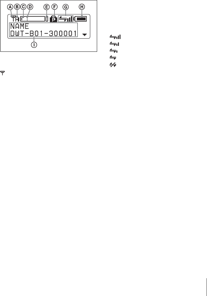
jDisplay section
ARF transmission indication
Indicates the current transmission status.
; Currently transmitting
—: Transmission stopped
BRF (radio frequency) transmission
power indication
Indicates the current transmission power
setting. You can change the setting with the
RF transmission power setting function.
H: transmitting at 50 mW
M: transmitting at 10 mW
L: transmitting at 1 mW
CAudio input level meter
Indicates the input signal level of the audio
input connector
DReference level gage
Indicates the reference input level. When
the attenuation is 0 dB with the input level
set to “mic”, –58 dBu (–60 dBV) is
indicated. When the line level is set, +4 dBu
is indicated.
EPeak indicator
Warns of excessive input by lighting up
when the signal is 3 dB below the level at
which distortion begins.
FPower switch lock indicator
Indicates that the power switch is locked,
preventing the transmitter from being
accidentally turned off or on.
For details, see “Locking the power switch (POWER
SW LOCK)” on page 24.
GWireless remote control condition
indication
Indicates the signal transmission condition
of the wireless remote control function (4
levels).
: Good transmission
: Somewhat good transmission
: Somewhat poor transmission
: Poor transmission
: Unable to communicate with paired
receiver
When the wireless remote control function
is off, this indication does not appear.
HBattery indication
Shows the battery condition.
For details, see “Battery indication” on page 14.
IMenu display section
The status of 15 different functions are
displayed here. To select the function, press
the + or – button repeatedly.
For details, See “Setting menus” on page 21.
14 Power supply
Power supply
The transmitter can operate on two LR6
(size AA) alkaline batteries continuously
for about 3.5 hours at 25°C (77°F).
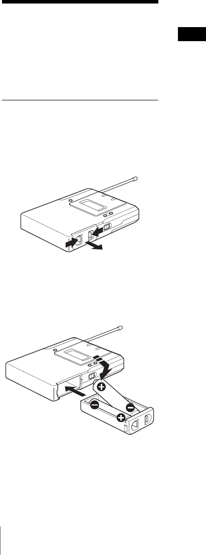
Installing the batteries
1Squeeze the battery-holder tabs inward
(in the direction of the arrows) and
slide out the battery holder.
2Insert new batteries, making sure the
polarities are correct, and then return
the battery holder to its original
position.
Battery indication
The power status is indicated by eight level
indications.
Replace both batteries when the battery
indication starts to flash.
Be sure to check the expiration date printed
date on the new batteries before using them.
The indication is based on the use of new
LR6 (size AA) Sony Alkaline batteries. An
incorrect indication may result when a
different kind of batteries, a different brand
of batteries or old batteries are used. If you
plan to use the transmitter for a long period
of time, it is recommended that you replace
the batteries with brand new ones.
Note

30 Important notes on operation
Important notes
on operation
Notes on using the
transmitter
• The digital wireless microphone system
product must be used within a
temperature range of 0°C to 50°C (32°F
to 122°F).
• Operating the transmitter near electrical
equipment (motors, transformers, or
dimmers) may cause it to be affected by
electromagnetic induction. Keep the
transmitter as far from such equipment as
possible.
• The presence of the lighting equipment
may produce electrical interference over
the entire frequency range. Position the
transmitter so that interference is
minimized.
• To avoid degradation of the signal-to-
noise ratio, do not use the transmitter in
noisy places or in locations subject to
vibration, such as the following:
- near electrical equipment, such as
motors, transformers or dimmers
- near air conditioning equipment or
places subject to direct air flow from
an air conditioner
- near public address loudspeakers
- where adjacent equipment might
knock against the tuner
Keep the transmitter as far from such
equipment as possible or use buffering
material.
On cleaning
• If the transmitter is used in a very humid
or dusty place or in a place subject to an
active gas, clean its surface as well as the
connectors with a dry, soft cloth soon
after use. Lengthy use of the transmitter
in such places or not cleaning it after its
use in such places may shorten its life.
• Clean the surface and the connectors of
the transmitter with a dry, soft cloth.
Never use thinner, benzene, alcohol or
any other chemicals, since these may mar
the finish.
To prevent electromagnetic
interference from portable
communication devices
The use of portable telephones and
other communication devices near
the DWT-B01 may result in
malfunction and interference with
audio signals. It is recommended that
portable communication devices near
the DWT-B01 be turned off.

31
Specifications
Specifications
Transmitting section
Oscillator type
Crystal-controlled PLL synthesizer
Carrier frequencies
US models:
U3040: 566 to 607 MHz (TV-30 to
TV-36 channels);
615 to 638 MHz (TV-38 to TV-
41 channels)
U4250: 638 to 698 MHz (TV-42 to
TV-51 channels)
European model:
CE6267: 798 to 822 MHz (TV-62
to TV-64 channels);
838 to 862 MHz (TV-67 to TV-
69 channels)
Channel step
US models:
U3040/U4250: 125 kHz
European model:
CE6267: 25 kHz
RF power output
1 mW/10 mW/50 mW (e.r.p)
selectable
Antenna type
λ/4 flexible wire
Occupied RF bandwidth
192 kHz or less
Audio delay
1.5 ms
Transmission frequency stability level
±6.5 ppm
Type of emission
G1E or G1D
Modulation method
π/4 Shift QPSK
Audio section
Maximum input level
MIC: –22 dBu (with 0 dB
attenuator)
LINE: +24 dBu
Audio attenuator adjustment range (pad)
0 to 48 dB (3dB steps, MIC input
mode only)
32 Specifications
Microphone input connector
Sony 4-pin (SMC9-4S) (female) (1)
Input impedance
4.7 kohms or more, 0 dBu = 0.775
V
Frequency response
20 Hz to 22 kHz
T.H.D 0.03% or less
Type of emission
G1E or G1D
Dynamic range
106 dB or more
General
Operating voltage
3 V DC, with two LR6 (AA)
alkaline batteries
Battery life
Continuous operating time
3.5 hours (at 25 °C (77 °F), 10-mW
output using Sony LR6 (AA)-
size alkaline batteries with the
wireless remote control
function off and the display set
to AUTO OFF)
Operating temperature
0 to 50 °C (32 to 122 °F)
Storage temperature
–20 to +60 °C (–4 to +140 °F)
Wireless remote control
2.4-GHz 1EEE802.15.4 compliant
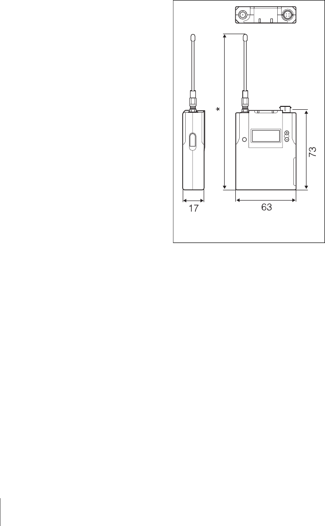
Dimensions
Approx. 63 x 73 x 17 mm
(2 1/2 x 2 7/8 x 11/16 inches) (W
x H x D) excluding projection
Mass Approx. 125 g (4 oz) including
batteries
Supplied accessories
Spare battery case (1)
Soft case (1)
Microphone cable (4-pin to XLR-
type 3-pin) (1)
USB adapter cable (1)
USB cable (1)
Carrying case (1)
Operating Instructions (1)
CD-ROM (Operating Instructions
and Sony Digital Wireless
Microphone System Frequency
Lists included) (1)
* CE7 model: 169
3040U model: 206
4250U model: 188
Unit: mm

33
Specifications
Optional accessories
ECM-/77BC/9X lavalier
microphones
Design and specifications are subject to
change without notice.
Note
Always verify that the unit is operating
properly before use. SONY WILL NOT
BE LIABLE FOR DAMAGES OF ANY
KIND INCLUDING, BUT NOT
LIMITED TO, COMPENSATION OR
REIMBURSEMENT ON ACCOUNT
OF THE LOSS OF PRESENT OR
PROSPECTIVE PROFITS DUE TO
FAILURE OF THIS UNIT, EITHER
DURING THE WARRANTY PERIOD
OR AFTER EXPIRATION OF THE
WARRANTY, OR FOR ANY OTHER
REASON WHATSOEVER.

This model has an RF module of the FCC/IC approval built-in.
BUILT IN MODULE RM-215
FCC ID: AK8RM215
IC: 409B-RM215