Sony Group S441C Sony Remote Card System Reader/Writer RC-S441C User Manual
Sony Corporation Sony Remote Card System Reader/Writer RC-S441C Users Manual
UserManual.wiki
>
Sony Group
>
S441C User Manual
Users Manual
Navigation menu
Upload a User Manual
Namespaces
Wiki Guide
HTML
PDF
Info
Views
User Manual
Discussion / Help
Navigation
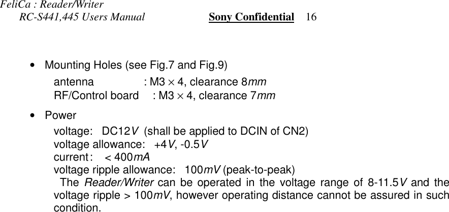
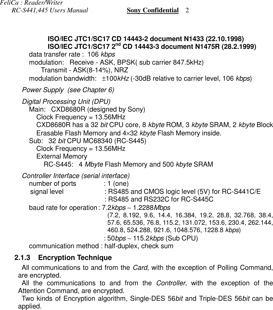
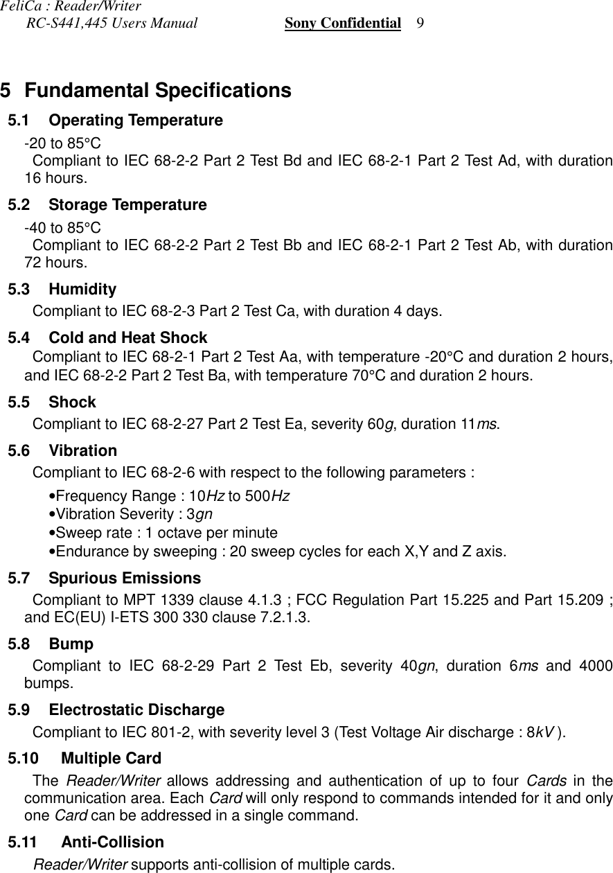
![FeliCa : Reader/Writer RC-S441,445 Users Manual Sony Confidential 11 DefinitionIn this document, following words are used in the following sense.Controller - An external computer, a gate controller or an equivalent equipment directlyconnected to Reader/Writer through specified wired interface.Reader/Writer - The equipment, specified in this document, for Sony Remote CardSystem : FeliCa.Card - A Contactless Smart Card for Sony Remote Card System : FeliCa2 General2.1 Basic SpecificationTable 1 shows Reader/Writer “RC-S44x” models. RC-S445 has dual CPUs andexternal memories for sub CPU. RC-S441 is a single CPU type same as the modelsRC-S430 and RC-S480.Reader/Writer consists of 3 parts – an antenna board, an RF/control board and thecable that connects the antenna board and the RF/control board. There are 2 antennatypes called Type C and E (see Chapter 6).Model No. CPU Memory AntennaTypeSerialInterface ConnectorTypeRC-S445C/6L Dual Flash 4MbyteSRAM 0.5Mbyte CRS485ARS232C Right angleRC-S441C/6L C StraightRC-S441E/6L Single - ERS485ACMOS Right angleTable 1 Reader/Writer RC-S44x models2.1.1 DimensionsThe dimension of each type are described in Chapter 6.The tolerance is ±0.5mm.2.1.2 Specification TableCommunication with Card( Common )carrier frequency: 13.56MHz (±50ppm)modulation bandwidth: ±300kHz (-30dB relative to carrier level)radiation level: less than 4500µV/m at 10m (Type C Antenna) 1000µV/m at 10m (Type E Antenna) 300µV/m at 10m (Type B Antenna)Communication method: half-duplex, CRC16( ISO type C )data transfer rate : 211.875kbpsmodulation: Receive - ASK, Manchester Coding Transmit - ASK(8-14%), Manchester Codingmodulation bandwidth: ±300kHz (-30dB relative to carrier level)( ISO type B )[Note] ISO/IEC document 14443 on the type B protocol was notpublished at the design stage of these Reader/Writer. The design wasmade according to then the newest available documents as describedbelow.](https://usermanual.wiki/Sony-Group/S441C/User-Guide-82979-Page-5.png)
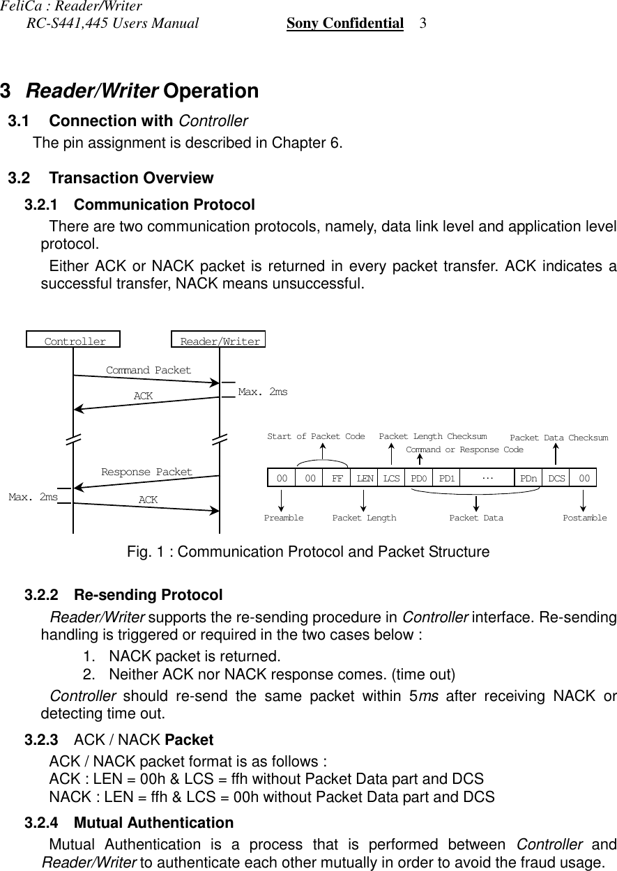
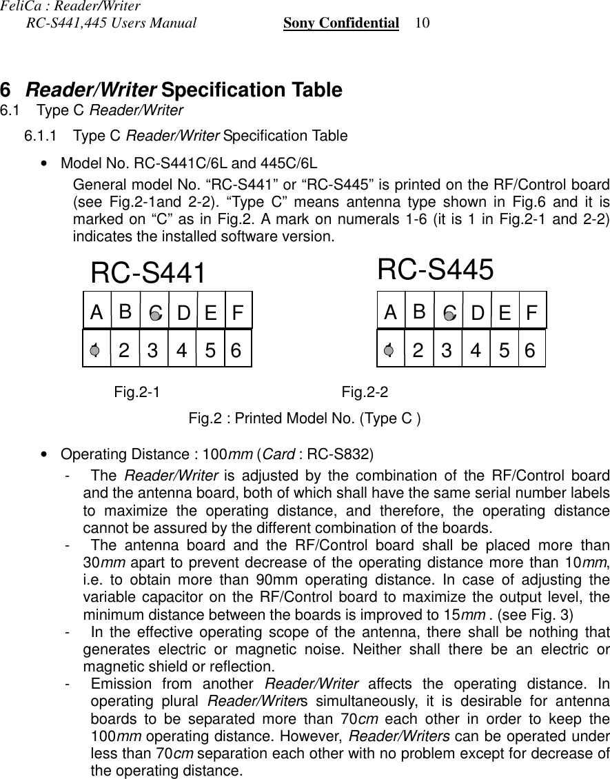
![FeliCa : Reader/Writer RC-S441,445 Users Manual Sony Confidential 11Fig.3 : Example of Antenna Placement (Type C)•Interface ConnectorRC-S441C/6L: Methode 1100-12-110-01 (straight)RC-S445C/6L: Methode 1100-12-110-02 (right angle) The interface connector is a 10-pin connector located at the right edge of theRF/Control board which is shown in the schematic drawing of Fig.7. The pitch ofconnector pins is 2.54mm. The most upper connector pin is No. 1. Pinassignment of the connector is shown in Fig. 4 and Table 5. Fig.4 : Pin Assignment of Connectors CN1-3 Pin No. 12345678910Pin Assignment SHDN GND DCIN RX- RX+ TX- TX+ TXD GND RXD Table 5 : Pin Assignment of Interface Connector CN3 AntennaControl boardd > 15mmExternal I/OTX+TX-RX+RX-5VGNDOUTIN TXDRXDSISOModu., Demodu. & Power Amp.*R/WRD*WDGND5VCARRIER*CARRIER12VRFIN+RFIN-RFOUT+RFOUT-EN/*INHController1SISOMODE5V*TORI*R/WCARRIER*CARRIEREN/*INHGNDDA[0-7]DB[0-7]HS[0-3]PA[0-7]GPSELCLKSIESCLKECC/*DCDSCR/*W*RESETCACKGR/*WData Conv. & Sel.GDAT[0-3]GPSEL5VGNDTO_IRI_OSCLKE_OSIE_OGACKGRQGC/*DGTOGRIGDSCLK*RESETGR/*WO1I1O2I2MI1MI2MO1MO2SOSIController2SISOMODE5VCLKGNDPA[0-7]PB[5-7]*RESETCACKDC-DC12V5VGNDINH5V5V5V12V5V5V5V12V12VDB[0-7]HS[0-3]DB[0-7]DA[0-7]HS[0-3]DA[0-7]SHDNTX+(RS485)TX-(RS485)GNDRXD(RS232C/CMOS)RX-(RS485)12VRX+(RS485)TXD(RS232C/CMOS)GNDto Ant.PB6PB5PB[5-7]PB7PA[0-7]TXDDB7DB2DB6DA7RX-DA0DB7DB1DA6MODE1DB5DA3DB3DA1 MODE2SOSIDB[0-3]DA2RX+GNDHS2DA5HS0GNDHS1DA4RXDTX+TX-DB6DB0DB4DB4GNDHS3GPSELGNDSHDNDB512V12VCN312345678910CN11234CN2CON40A13579111315171921232527293133353739246810121416182022242628303234363840FUSE](https://usermanual.wiki/Sony-Group/S441C/User-Guide-82979-Page-15.png)