Sony Group S445C Sony Remote Card System Reader/Writer RC-S445C User Manual
Sony Corporation Sony Remote Card System Reader/Writer RC-S445C
User Manual

Sony Confidential
FeliCa Reader/Writer RC-S441C and RC-S445C
- Users Manual -
(Version 2.10)
Sony Corporation
19 November 1999
“FeliCa” is a trademark of Sony Corporation
Contents
1 Definition 1
2 General 1
2.1 Basic Specification 1
2.1.1 Dimensions 1

FeliCa: Reader/Writer
RC-S441,445 Users Manual Sony Confidential ii
2.1.2 Specification Table 1
2.1.3 Encryption Technique 2
3 Reader/Writer Operation 3
3.1 Connection with Controller 3
3.2 Transaction Overview 3
3.2.1 Communication Protocol 3
3.2.2 Re-sending Protocol 3
3.2.3 ACK/NACK Packet 3
3.2.4 Mutual Authentication 3
3.2.5 Encryption and Decryption 4
4 Communication Commands 4
4.1 General 4
4.2 Reader/Writer Internal Operation Commands 4
4.2.1 Attention Command 4
4.2.2 Authentication 1 Command 4
4.2.3 Authentication 2 Command 4
4.2.4 Disconnect Command 4
4.2.5 Change Reader/Writer Access Key Command 4
4.2.6 Self-Diagnosis Command 6
4.2.7 Check Firmware Version Command 6
4.2.8 Change Communication Mode Command 6
4.2.9 Kill Module Command 6
4.2.10 Reader/Writer Reset Command 6
4.2.11 Firmware Maintenance Command 6
4.3 Card Operation Command 6
4.3.1 Polling Command 6
4.3.2 Request Service Command 6
4.3.3 Request Response Command 6
4.3.4 Mutual Authentication Command 6
4.3.5 Read Block Command 6
4.3.6 Write Block Command 7
4.3.7 Release Command 7
4.3.8 Read Without Encryption Command 7
4.3.9 Write Without Encryption Command 7
4.4 Card Management Command 8
4.4.1 Register Issue ID Command 8
4.4.2 Register Area Command 8
4.4.3 Register Service Command 8
4.4.4 Register Manufacture ID Command 8
4.4.5 Card Self-Diagnosis Common Security Key Command 8
5 Fundamental Specifications 9
5.1 Operating Temperature 9
5.2 Storage Temperature 9
5.3 Humidity 9
5.4 Cold and Heat Shock 9
5.5 Shock 9
5.6 Vibration 9
5.7 Spurious Emissions 9
5.8 Bump 9
5.9 Electrostatic Discharge 9
5.10 Multiple cards 9
5.11 Anti-Collision 9

FeliCa: Reader/Writer
RC-S441,445 Users Manual Sony Confidential iii
6Reader/Write Specification Table 10
6.1 Type C Reader/Writer 10
6.1.1 Type C Reader/Writer Specification Table 10
•Model No. 10
•Operating Distance 10
•Interface Connector 11
•External Interface 12
•Dimensions 13
•Mounting Holes 13
•Power 13
6.1.2 Type C Reader/Writer Schematic Drawing 13
6.2 Type E Reader/Writer 15
6.2.1 Type E Reader/Writer Specification Table 15
•Model No. 15
•Operating Distance 15
•Interface Connector 15
•External Interface 15
•Dimensions 16
•Mounting Holes 16
•Power 16
6.2.2 Type E Reader/Writer Schematic Drawing 17

FeliCa: Reader/Writer
RC-S441,445 Users Manual Sony Confidential iv
List of Table
Table 1 Reader/Writer RC-S44x Models 1
Table 2 Reader/Writer Internal Operation Command 4
Table 3 Card Operation Command 4
Table 4 Card Management Command 4
Table 5 Pin Assignment of Interface Connector CN2 12
List of Figures
Fig.1 Communication Protocol and Packet Structure 3
Fig.2 Printed Model No. (type C) 10
Fig.3 Example of Antenna Placement (type C) 11
Fig.4 Pin Assignment of Connectors CN1-3 11
Fig.5 Placement of Parts for RS-232C Interface 12
Fig.6 Antenna Board (type C) 13
Fig.7 RF/Control Board 14
Fig.8 Printed Model No. (type E) 15
Fig.9 Antenna Board (type E) 17

FeliCa : Reader/Writer
RC-S441,445 Users Manual Sony Confidential 1
1 Definition
In this document, following words are used in the following sense.
Controller - An external computer, a gate controller or an equivalent equipment directly
connected to Reader/Writer through specified wired interface.
Reader/Writer - The equipment, specified in this document, for Sony Remote Card
System : FeliCa.
Card - A Contactless Smart Card for Sony Remote Card System : FeliCa
2 General
2.1 Basic Specification
Table 1 shows Reader/Writer “RC-S44x” models. RC-S445 has dual CPUs and
external memories for sub CPU. RC-S441 is a single CPU type same as the models
RC-S430 and RC-S480.
Reader/Writer consists of 3 parts – an antenna board, an RF/control board and the
cable that connects the antenna board and the RF/control board. There are 2 antenna
types called Type C and E (see Chapter 6).
Model No. CPU Memory Antenna
Type
Serial
Interface Connector
Type
RC-S445C/6L Dual Flash 4Mbyte
SRAM 0.5Mbyte CRS485A
RS232C Right angle
RC-S441C/6L C Straight
RC-S441E/6L Single - E
RS485A
CMOS Right angle
Table 1 Reader/Writer RC-S44x models
2.1.1 Dimensions
The dimension of each type are described in Chapter 6.
The tolerance is ±0.5mm.
2.1.2 Specification Table
Communication with Card
( Common )
carrier frequency: 13.56MHz (±50ppm)
modulation bandwidth: ±300kHz (-30dB relative to carrier level)
radiation level: less than 4500
µ
V/m at 10m (Type C Antenna)
1000
µ
V/m at 10m (Type E Antenna)
300
µ
V/m at 10m (Type B Antenna)
Communication method: half-duplex, CRC16
( ISO type C )
data transfer rate : 211.875kbps
modulation: Receive - ASK, Manchester Coding
Transmit - ASK(8-14%), Manchester Coding
modulation bandwidth: ±300kHz (-30dB relative to carrier level)
( ISO type B )
[Note] ISO/IEC document 14443 on the type B protocol was not
published at the design stage of these Reader/Writer. The design was
made according to then the newest available documents as described
below.

FeliCa : Reader/Writer
RC-S441,445 Users Manual Sony Confidential 2
ISO/IEC JTC1/SC17 CD 14443-2 document N1433 (22.10.1998)
ISO/IEC JTC1/SC17 2nd CD 14443-3 document N1475R (28.2.1999)
data transfer rate : 106 kbps
modulation: Receive - ASK, BPSK( sub carrier 847.5kHz)
Transmit - ASK(8-14%), NRZ
modulation bandwidth: ±100kHz (-30dB relative to carrier level, 106 kbps)
Power Supply (see Chapter 6)
Digital Processing Unit (DPU)
Main: CXD8680R (designed by Sony)
Clock Frequency = 13.56MHz
CXD8680R has a 32 bit CPU core, 8 kbyte ROM, 3 kbyte SRAM, 2 kbyte Block
Erasable Flash Memory and 4×32 kbyte Flash Memory inside.
Sub: 32 bit CPU MC68340 (RC-S445)
Clock Frequency = 13.56MHz
External Memory
RC-S445: 4 Mbyte Flash Memory and 500 kbyte SRAM
Controller Interface (serial interface)
number of ports : 1 (one)
signal level : RS485 and CMOS logic level (5V) for RC-S441C/E
: RS485 and RS232C for RC-S445C
baud rate for operation: 7.2kbps ∼ 1.2288Mbps
(7.2, 8.192, 9.6, 14.4, 16.384, 19.2, 28.8, 32.768, 38.4,
57.6, 65.536, 76.8, 115.2, 131.072, 153.6, 230.4, 262.144,
460.8, 524.288, 921.6, 1048.576, 1228.8 kbps)
: 50bps ∼ 115.2kbps (Sub CPU)
communication method : half-duplex, check sum
2.1.3 Encryption Technique
All communications to and from the Card, with the exception of Polling Command,
are encrypted.
All the communications to and from the Controller, with the exception of the
Attention Command, are encrypted.
Two kinds of Encryption algorithm, Single-DES 56bit and Triple-DES 56bit can be
applied.
FeliCa : Reader/Writer
RC-S441,445 Users Manual Sony Confidential 3
3Reader/Writer Operation
3.1 Connection with Controller
The pin assignment is described in Chapter 6.
3.2 Transaction Overview
3.2.1 Communication Protocol
There are two communication protocols, namely, data link level and application level
protocol.
Either ACK or NACK packet is returned in every packet transfer. ACK indicates a
successful transfer, NACK means unsuccessful.
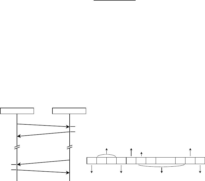
Fig. 1 : Communication Protocol and Packet Structure
3.2.2 Re-sending Protocol
Reader/Writer supports the re-sending procedure in Controller interface. Re-sending
handling is triggered or required in the two cases below :
1. NACK packet is returned.
2. Neither ACK nor NACK response comes. (time out)
Controller should re-send the same packet within 5ms after receiving NACK or
detecting time out.
3.2.3 ACK / NACK Packet
ACK / NACK packet format is as follows :
ACK : LEN = 00h & LCS = ffh without Packet Data part and DCS
NACK : LEN = ffh & LCS = 00h without Packet Data part and DCS
3.2.4 Mutual Authentication
Mutual Authentication is a process that is performed between Controller and
Reader/Writer to authenticate each other mutually in order to avoid the fraud usage.
Reader/WriterController
Max. 2ms
Command Packet
ACK
ACK
Max. 2ms
Response Packet 00 FF00 LEN LCS PD0PDnPD1DCS 00
…
Postamble
Packet Data Checksum
Packet Data
Packet Length Checksum
Start of Packet Code
Packet Length
Preamble
Command or Response Code

FeliCa : Reader/Writer
RC-S441,445 Users Manual Sony Confidential 4
This authentication is based on the following elements :
1. two 8byte (64bit) keys
2. three pass authentication model (ISO 9758)
3. cryptography algorithm mentioned in section 3.2.5.
3.2.5 Encryption and Decryption
The cryptography algorithm is used for the following three stages :
1. mutual authentication between Controller and Reader/Writer
2. mutual authentication between Reader/Writer and Card
3. commands and data encryption through Reader/Writer
4 Communication Commands
4.1 General
In this section, the communication commands between Controller and Reader /Writer
are described.
Table 2-4 shows all commands between Controller and general Reader/Writer. All
commands are categorized into 3 groups as follows :
1. Reader/Writer internal operation command
2. Card operation command
3. Card management command
Card management command group is for issue Reader/Writer and not for general
Reader/Writer .
4.2 Reader/Writer Internal Operation Command
4.2.1 Attention Command
Attention Command enables Reader/Writer and Controller to recognize each other
and is the only command available before the authentication completes. The main
purpose of this Attention Command is to recognize its partner before authentication
and to force Reader/Writer to be in the idle state.
4.2.2 Authentication 1 Command
Authentication 1 Command enables Controller to authenticate Reader/Writer.
4.2.3 Authentication 2 Command
Authentication 2 Command enables Reader/Writer to authenticate Controller.
4.2.4 Disconnect Command
Disconnect Command is for Controller to terminate the communication with
Reader/Writer.
4.2.5 Change Reader/Writer Access Key Command
Change Reader/Writer Access Key Command performs alteration of the access
keys, which are stored in Reader/Writer for the mutual authentication between
Controller and Reader/Writer.
FeliCa : Reader/Writer
RC-S441,445 Users Manual Sony Confidential 5
Command Command Code Response Code
Attention 00h 01h
Authentication 1 02h 03h
Authentication 2 04h 05h
Disconnect 06h 07h
Change Reader/Writer Access Key 20h 21h
Self-Diagnosis 40h 41h
Check Firmware Version 44h 45h
Change Communication Mode 46h 47h
Kill Module 4ah 4bh
Reader/Writer Reset 4ch 4dh
Firmware Maintenance 52h 53h
Table 2 : Reader/Writer Internal Operation Command
Command Command Code Response Code
Polling 80h 81h
Request Service 82h 83h
Request Response 84h 85h
Mutual Authentication 86h 87h
Read Block 88h 89h
Write Block 8ah 8bh
Release 8eh 8fh
Read Without Encryption 98h 99h
Write Without Encryption 9ah 9bh
Table 3 : Card Operation Command
Command Command Code Response Code
Register Issue ID c0h c1h
Register Area c2h c3h
Register Service c4h c5h
Register Manufacture ID e0h e1h
Card Self-Diagnosis f0h f1h
Table 4 : Card Management Command

FeliCa : Reader/Writer
RC-S441,445 Users Manual Sony Confidential 6
4.2.6 Self-Diagnosis Command
Self-Diagnosis Command activates self-diagnosis test of Reader/Writer. After the
Diagnosis completion, Reader/Writer sends back the test result.
4.2.7 Check Firmware Version Command
Check Firmware Version Command is used for checking the version of
Reader/Writer firmware.
4.2.8 Change Communication Mode Command
Change Communication Mode Command performs the following changes : baud
rate, logic level interface(non-inverted or inverted), encryption on/off, time-out.
4.2.9 Kill Module Command
Kill Module Command is used for killing the specified module within Reader/Writer.
4.2.10 Reader/Writer Reset Command
Reader/Writer Reset Command executes the initialization routine.
4.2.11 Firmware Maintenance Command
Firmware Maintenance Command is used for updating the firmware within
Reader/Writer.
4.3 Card Operation Command
4.3.1 Polling Command
Polling Command enables Reader/Writer to give a call to Card and to detect
existence of Card by the response from Card.
4.3.2 Request Service Command
Request Service Command enables Reader/Writer to check whether the specified
service code is registered to Card or not. In case that the specified service is
registered to Card, key version of the service is available by the response from Card.
4.3.3 Request Response Command
Request Response Command enables Reader/Writer to check which mode Card is
in. There are 4 modes, ‘before Authentication’, ‘after Authentication 1’, ‘after
Authentication 2’ and ‘after Register xxx Command (see 4.4 Card Management
Command)’.
4.3.4 Mutual Authentication Command
Mutual Authentication Command activates the mutual authentication procedure
between Reader/Writer and Card.
4.3.5 Read Block Command
Read Block Command activates Reader/Writer to read the specified block data from
Card after the mutual authentication between the Reader/Writer and Card has been
established successfully.
Read Block Command enables a Service Provider with successful mutual
authentication to read blocks that this Service Provider has the right to access.
With one Read Block Command, up to 8 block can be read simultaneously. If more
than 8 blocks should be read, more than one Read Block Command shall be called
separately.
The response of Read Block Command is a 1byte Read result and Block Data that
has been read. In the Read result, a 1byte consequence of one block Read is given
in 1bit. As there are up to 8 blocks, 1byte is enough to record all the Read
consequence.

FeliCa : Reader/Writer
RC-S441,445 Users Manual Sony Confidential 7
4.3.6 Write Block Command
Write Block Command activates Reader/Writer to write the specified block data to
Card as new data after the mutual authentication between Reader/writer and Card
has been established successfully.
With one Write Block Command, up to 8 block can be written simultaneously. If
more than 8 blocks should be written, more than one Write Block Command shall be
called separately.
The response of Write Block Command is a 1byte Write result. In the Write result, a
1byte consequence of one block Write is given in 1bit. As there are up to 8 blocks,
1byte is enough to record all the Write consequence.
The purse operation can be performed with Write Block Command.
4.3.7 Release Command
Release Command enables Card to be released from established communication
sequence with Reader/Writer.
4.3.8 Read Without Encryption Command
Read Without Encryption Command activates Reader/Writer to read the specified
block data from Card without the mutual authentication between the Reader/Writer
and Card. Read Without Encryption Command can be applied only to blocks which
service code is registered security-free.
The number of blocks that can be read simultaneously and the response of Read
Without Encryption Command are the same as those for Read Block Command (see
4.3.5).
4.3.9 Write Without Encryption Command
Write Without Encryption Command activates Reader/Writer to write the specified
block data to Card without the mutual authentication between the Reader/Writer and
Card, however can be applied only to blocks which service code is registered
security-free.
The number of blocks that can be write simultaneously and the response of Write
Without Encryption Command are the same as those for Write Block Command (see
4.3.6).

FeliCa : Reader/Writer
RC-S441,445 Users Manual Sony Confidential 8
4.4 Card Management Command
The commands described in this section are for issue Reader/Writer and not for
general Reader/Writer .
4.4.1 Register Issue ID Command
Register Issue ID Command makes it possible to register Issue ID(IDi) , Issue
Parameter(PMi), System Code and Area 0000 Key to Card, and also makes it to
erase other services and to initialize Memory Allocation Information in Card.
4.4.2 Register Area Command
Register Area Command makes it possible to register new Area and the parameters
of new Area to Card, which are Service Code Range, Available Block Number and
Area Key.
4.4.3 Register Service Command
Register Service Command makes it possible to register new Service and the
parameters of new Service to Card, which are Service Code, Block Number and
Service Key.
4.4.4 Register Manufacture ID Command
Register Manufacture ID Command makes it possible to register Manufacture
ID(IDm) , Manufacture Parameter(PMm), System Code, System Key and Area 0000
Key to Card, and also makes it to clear Issue ID of Card.
In order to execute Register Manufacture ID Command, Manufacture ID must be all
00h. This means that Register Manufacture ID Command is effective to Card once for
all.
4.4.5 Card Self-Diagnosis Command
Card Self-Diagnosis Command activates self-diagnosis test of Card. After the
Diagnosis completion, Card sends back the test result.

FeliCa : Reader/Writer
RC-S441,445 Users Manual Sony Confidential 9
5 Fundamental Specifications
5.1 Operating Temperature
-20 to 85°C
Compliant to IEC 68-2-2 Part 2 Test Bd and IEC 68-2-1 Part 2 Test Ad, with duration
16 hours.
5.2 Storage Temperature
-40 to 85°C
Compliant to IEC 68-2-2 Part 2 Test Bb and IEC 68-2-1 Part 2 Test Ab, with duration
72 hours.
5.3 Humidity
Compliant to IEC 68-2-3 Part 2 Test Ca, with duration 4 days.
5.4 Cold and Heat Shock
Compliant to IEC 68-2-1 Part 2 Test Aa, with temperature -20°C and duration 2 hours,
and IEC 68-2-2 Part 2 Test Ba, with temperature 70°C and duration 2 hours.
5.5 Shock
Compliant to IEC 68-2-27 Part 2 Test Ea, severity 60g, duration 11ms.
5.6 Vibration
Compliant to IEC 68-2-6 with respect to the following parameters :
•Frequency Range : 10Hz to 500Hz
•Vibration Severity : 3gn
•Sweep rate : 1 octave per minute
•Endurance by sweeping : 20 sweep cycles for each X,Y and Z axis.
5.7 Spurious Emissions
Compliant to MPT 1339 clause 4.1.3 ; FCC Regulation Part 15.225 and Part 15.209 ;
and EC(EU) I-ETS 300 330 clause 7.2.1.3.
5.8 Bump
Compliant to IEC 68-2-29 Part 2 Test Eb, severity 40gn, duration 6ms and 4000
bumps.
5.9 Electrostatic Discharge
Compliant to IEC 801-2, with severity level 3 (Test Voltage Air discharge : 8kV ).
5.10 Multiple Card
The Reader/Writer allows addressing and authentication of up to four Cards in the
communication area. Each Card will only respond to commands intended for it and only
one Card can be addressed in a single command.
5.11 Anti-Collision
Reader/Writer supports anti-collision of multiple cards.
FeliCa : Reader/Writer
RC-S441,445 Users Manual Sony Confidential 10
6Reader/Writer Specification Table
6.1 Type C Reader/Writer
6.1.1 Type C Reader/Writer Specification Table
•Model No. RC-S441C/6L and 445C/6L
General model No. “RC-S441” or “RC-S445” is printed on the RF/Control board
(see Fig.2-1and 2-2). “Type C” means antenna type shown in Fig.6 and it is
marked on “C” as in Fig.2. A mark on numerals 1-6 (it is 1 in Fig.2-1 and 2-2)
indicates the installed software version.
Fig.2-1 Fig.2-2
Fig.2 : Printed Model No. (Type C )
•Operating Distance : 100mm (Card : RC-S832)
- The Reader/Writer is adjusted by the combination of the RF/Control board
and the antenna board, both of which shall have the same serial number labels
to maximize the operating distance, and therefore, the operating distance
cannot be assured by the different combination of the boards.
- The antenna board and the RF/Control board shall be placed more than
30mm apart to prevent decrease of the operating distance more than 10mm,
i.e. to obtain more than 90mm operating distance. In case of adjusting the
variable capacitor on the RF/Control board to maximize the output level, the
minimum distance between the boards is improved to 15mm . (see Fig. 3)
- In the effective operating scope of the antenna, there shall be nothing that
generates electric or magnetic noise. Neither shall there be an electric or
magnetic shield or reflection.
- Emission from another Reader/Writer affects the operating distance. In
operating plural Reader/Writers simultaneously, it is desirable for antenna
boards to be separated more than 70cm each other in order to keep the
100mm operating distance. However, Reader/Writers can be operated under
less than 70cm separation each other with no problem except for decrease of
the operating distance.
RC-S445
A
BDCE
F
123456
RC-S441
A
BDCE
F
123456
FeliCa : Reader/Writer
RC-S441,445 Users Manual Sony Confidential 11
Fig.3 : Example of Antenna Placement (Type C)
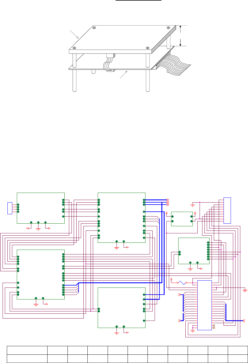
•Interface Connector
RC-S441C/6L: Methode 1100-12-110-01 (straight)
RC-S445C/6L: Methode 1100-12-110-02 (right angle)
The interface connector is a 10-pin connector located at the right edge of the
RF/Control board which is shown in the schematic drawing of Fig.7. The pitch of
connector pins is 2.54mm. The most upper connector pin is No. 1. Pin
assignment of the connector is shown in Fig. 4 and Table 5.
Fig.4 : Pin Assignment of Connectors CN1-3
Pin No. 12345678910
Pin Assignment SHDN GND DCIN RX- RX+ TX- TX+ TXD GND RXD
Table 5 : Pin Assignment of Interface Connector CN3
Antenna
Control board
d > 15mm
External I/O
TX+
TX-
RX+
RX-
5V
GND
OUT
IN TXD
RXD
SI
SO
Modu., Demodu. & Power Amp.
*R/W
RD
*WD
GND
5V
CARRIER
*CARRIER
12V
RFIN+
RFIN-
RFOUT+
RFOUT-
EN/*INH
Controller1
SI
SO
MODE
5V
*TO
RI
*R/W
CARRIER
*CARRIER
EN/*INH
GND
DA[0-7]
DB[0-7]
HS[0-3]
PA[0-7]
GPSEL
CLK
SIE
SCLKE
CC/*D
CDS
CR/*W
*RESET
CACKGR/*W
Data Conv. & Sel.
GDAT[0-3]
GPSEL
5V
GND
TO_I
RI_O
SCLKE_O
SIE_O
GACK
GRQ
GC/*D
GTO
GRI
GDSCLK
*RESET
GR/*W
O1
I1
O2
I2
MI1
MI2
MO1
MO2
SO
SI
Controller2
SI
SO
MODE
5V
CLK
GND
PA[0-7]
PB[5-7]
*RESET
CACK
DC-DC
12V5V
GNDINH
5V
5V
5V12V
5V
5V
5V
12V
12V
DB[0-7]
HS[0-3]
DB[0-7]
DA[0-7]
HS[0-3]
DA[0-7]
SHDN
TX+(RS485)
TX-(RS485)
GND
RXD(RS232C/CMOS)
RX-(RS485)
12V
RX+(RS485)
TXD(RS232C/CMOS)
GND
to Ant.
PB6
PB5
PB[5-7]
PB7
PA[0-7]
TXD
DB7
DB2
DB6
DA7
RX-
DA0
DB7
DB1
DA6
MODE1
DB5
DA3
DB3
DA1 MODE2
SO
SI
DB[0-3]
DA2
RX+
GND
HS2
DA5
HS0
GND
HS1
DA4
RXD
TX+
TX-
DB6
DB0
DB4
DB4
GND
HS3
GPSEL
GND
SHDN
DB5
12V
12V
CN3
1
2
3
4
5
6
7
8
9
10
CN1
1
2
3
4
CN2
CON40A
1
3
5
7
9
11
13
15
17
19
21
23
25
27
29
31
33
35
37
39
2
4
6
8
10
12
14
16
18
20
22
24
26
28
30
32
34
36
38
40
FUSE
FeliCa : Reader/Writer
RC-S441,445 Users Manual Sony Confidential 12
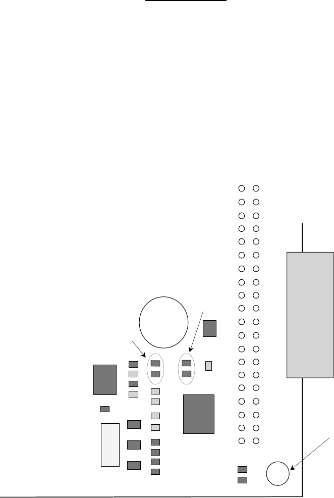
•External Interface
serial 1 port: RS-485A and CMOS logic level (5V) for RC-S441C
RS485A and RS232C for RC-S445C
software selectable, non-inverted or inverted, and baud rate
(default setting : non-inverted, 115.2kbps)
Common pins are assigned for RS-232C and CMOS logic level. CMOS logic
level can be available instead of RS232C for RC-S445C by mounting 2 resistors
R46-47 and removing 2 resistors R52-53 which are located near the right, lower
corner of the RF/Control board as shown in Fig.5.
Fig.5 : Placement of Parts for RS-232C or CMOS Interface
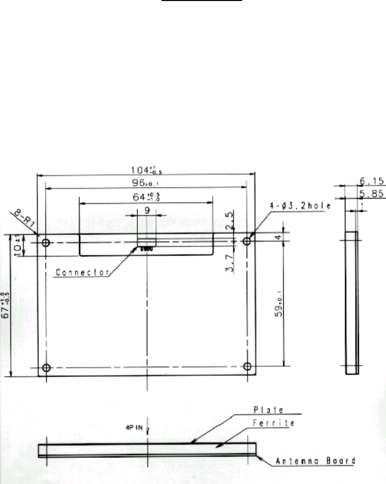
•Dimensions (see Fig.6 and Fig.7)
antenna: 104mm × 67mm × 6mm
(PCB thickness 1mm, connector height 5mm)
RF/Control board: 104mm × 67mm × 10.5mm (PCB thickness 1mm)
cable: length 120mm
•Mounting Holes (see Fig.6 and Fig.7)
antenna : M3 × 4, clearance 8mm
RF/Control board : M3 × 4, clearance 7mm
•Power
voltage: DC12V (shall be applied to DCIN of CN2)
CN3
IC10 Mounting Hole
R47
R46
R53
R52
RF/Control Board (0-881-428-02)
1
10
1
2
39
40
CN3
CMOS Logic Level
R46,47 : < 10 ohm
R52,53 : no mounting
RS-232C
R46,47 : no mounting
R52,53 : < 10 ohm
IC10 : MAX3221CAE
FeliCa : Reader/Writer
RC-S441,445 Users Manual Sony Confidential 13
voltage allowance: +4V, -0.5V
current: < 400mA
voltage ripple allowance: 100mV (peak-to-peak)
The Reader/Writer can be operated in the voltage range of 8-11.5V and the
voltage ripple > 100mV, however operating distance cannot be assured in such
condition.
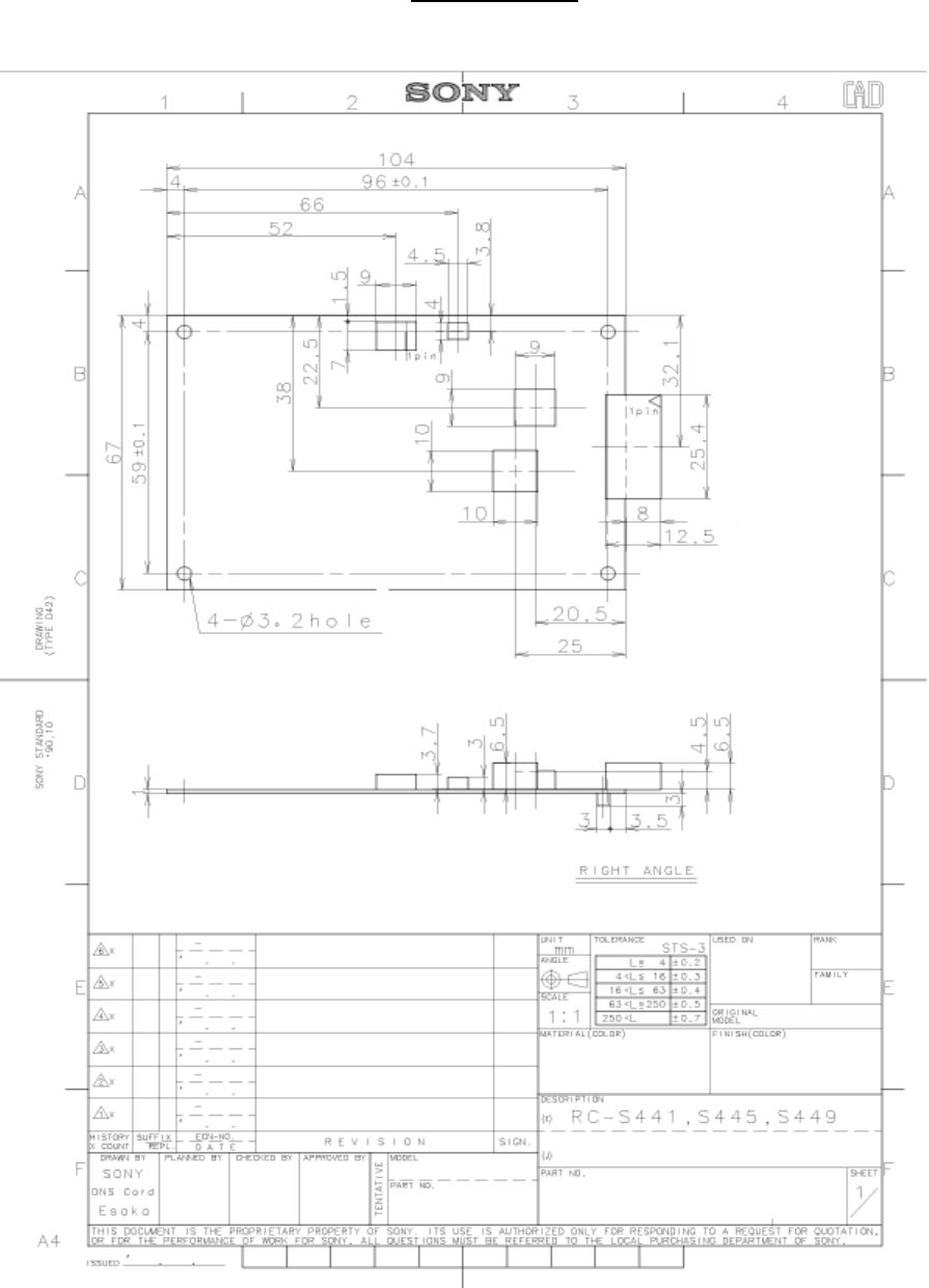
6.1.2 Type C Reader/Writer Schematic Drawing
Fig.6 : Antenna Board (Type C)
FeliCa : Reader/Writer
RC-S441,445 Users Manual Sony Confidential 14
Fig.7 : RF/Control Board

FeliCa : Reader/Writer
RC-S441,445 Users Manual Sony Confidential 15
6.2 Type E Reader/Writer (Limited Model)
6.2.1 Type E Reader/Writer Specification Table
•Model No. : RC-S441E/6L
General model No. “RC-S441” is printed on the RF/Control board (see Fig.8).
“Type E” means antenna type shown in Fig.9 and it is marked on “E” as in Fig.8.
A mark on numerals 1-6 (it is 1 in Fig.8) indicates the installed software version.
Fig.8 : Printed Model No. (Type E )
•Operating Distance : 40mm (Card : RC-S832)
- The Reader/Writer is adjusted by the combination of the RF/Control board
and the antenna board, both of which shall have the same serial number labels
to maximize the operating distance, and therefore, the operating distance
cannot be assured by the different combination of the boards.
- The antenna board and the RF/Control board shall be placed more than
30mm apart.
- In the effective operating scope of the antenna, there shall be nothing that
generates electric or magnetic noise. Neither shall there be an electric or
magnetic shield or reflection. Type E antenna is affected by conductive
material more easily than other antenna types because a ferrite block is not
attached on the antenna board.
- Emission from another Reader/Writer affects the operating distance. In
operating plural Reader/Writers simultaneously, it is desirable for antenna
boards to be separated more than 50cm each other in order to keep the
40mm operating distance. However, Reader/Writers can be operated under
less than 50cm separation each other with no problem except for decrease of
the operating distance.
•Interface Connector : Methode 1100-12-110-02 (right angle)
The interface connector is a 10-pin connector located at the right edge of the
RF/Control board which is shown in the schematic drawing of Fig.7. The pitch of
connector pins is 2.54mm. The most upper connector pin is No. 1. Pin
assignment of the connector is shown in Fig. 4 and Table 5.
•External Interface
serial 1 port : RS-485A, CMOS logic level (5V)
software selectable, non-inverted or inverted, and baud rate
(default setting : non-inverted, 115.2kbps)
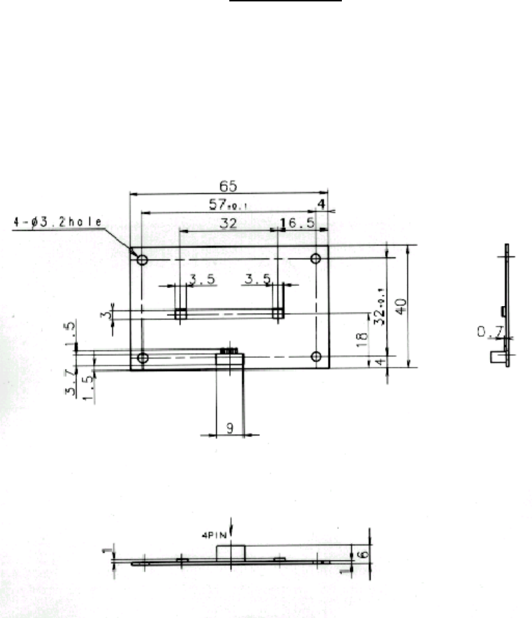
•Dimensions (see Fig.7 and Fig.9)
antenna: 65mm × 40mm × 6mm
(PCB thickness 1mm, connector height 5mm)
RF/Control board: 104mm × 67mm × 10.5mm (PCB thickness 1mm)
cable: length 120mm
RC-S441
A
BDCE
F
123456

FeliCa : Reader/Writer
RC-S441,445 Users Manual Sony Confidential 16
•Mounting Holes (see Fig.7 and Fig.9)
antenna : M3 × 4, clearance 8mm
RF/Control board : M3 × 4, clearance 7mm
•Power
voltage: DC12V (shall be applied to DCIN of CN2)
voltage allowance: +4V, -0.5V
current: < 400mA
voltage ripple allowance: 100mV (peak-to-peak)
The Reader/Writer can be operated in the voltage range of 8-11.5V and the
voltage ripple > 100mV, however operating distance cannot be assured in such
condition.
FeliCa : Reader/Writer
RC-S441,445 Users Manual Sony Confidential 17
6.2.2 Type E Reader/Writer Schematic Drawing
Fig.9 : Antenna Board (Type E)