Sony Group SNCM1W Network Camera User Manual SNC M1 M1W
Sony Corporation Network Camera SNC M1 M1W
UserManual.wiki
>
Sony Group
>
SNCM1W User Manual
Manual revised
Navigation menu
Upload a User Manual
Namespaces
Wiki Guide
HTML
PDF
Info
Views
User Manual
Discussion / Help
Navigation
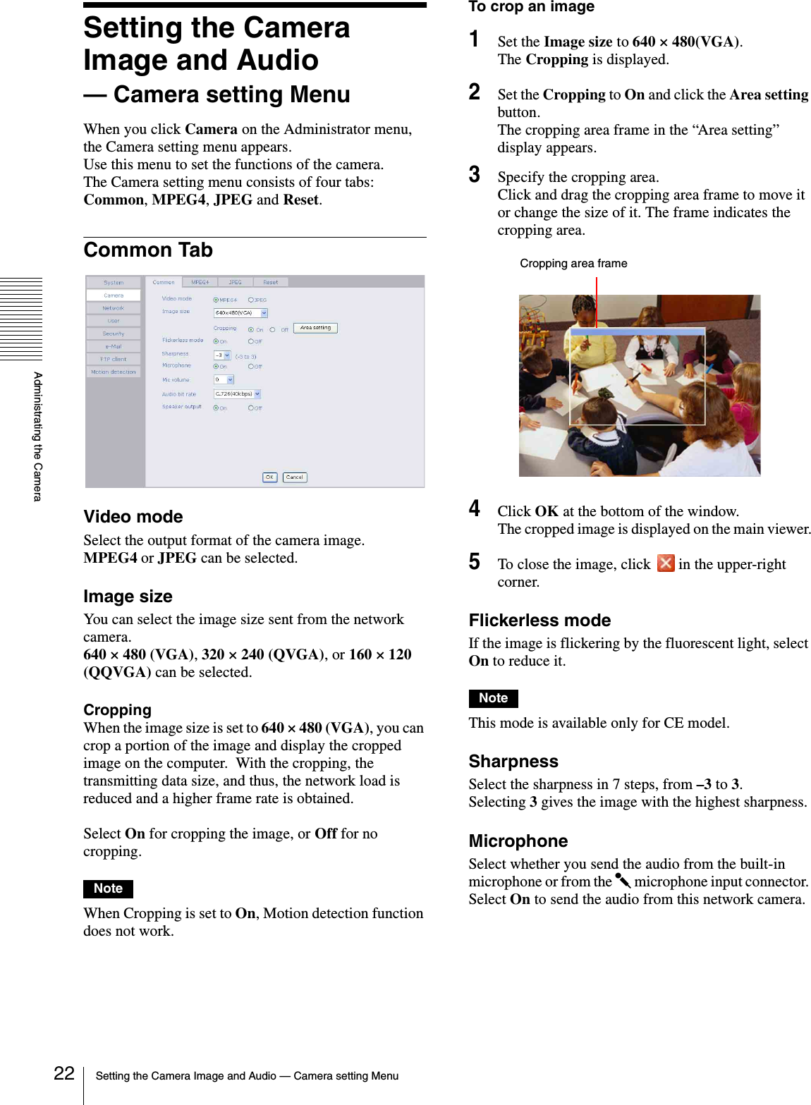
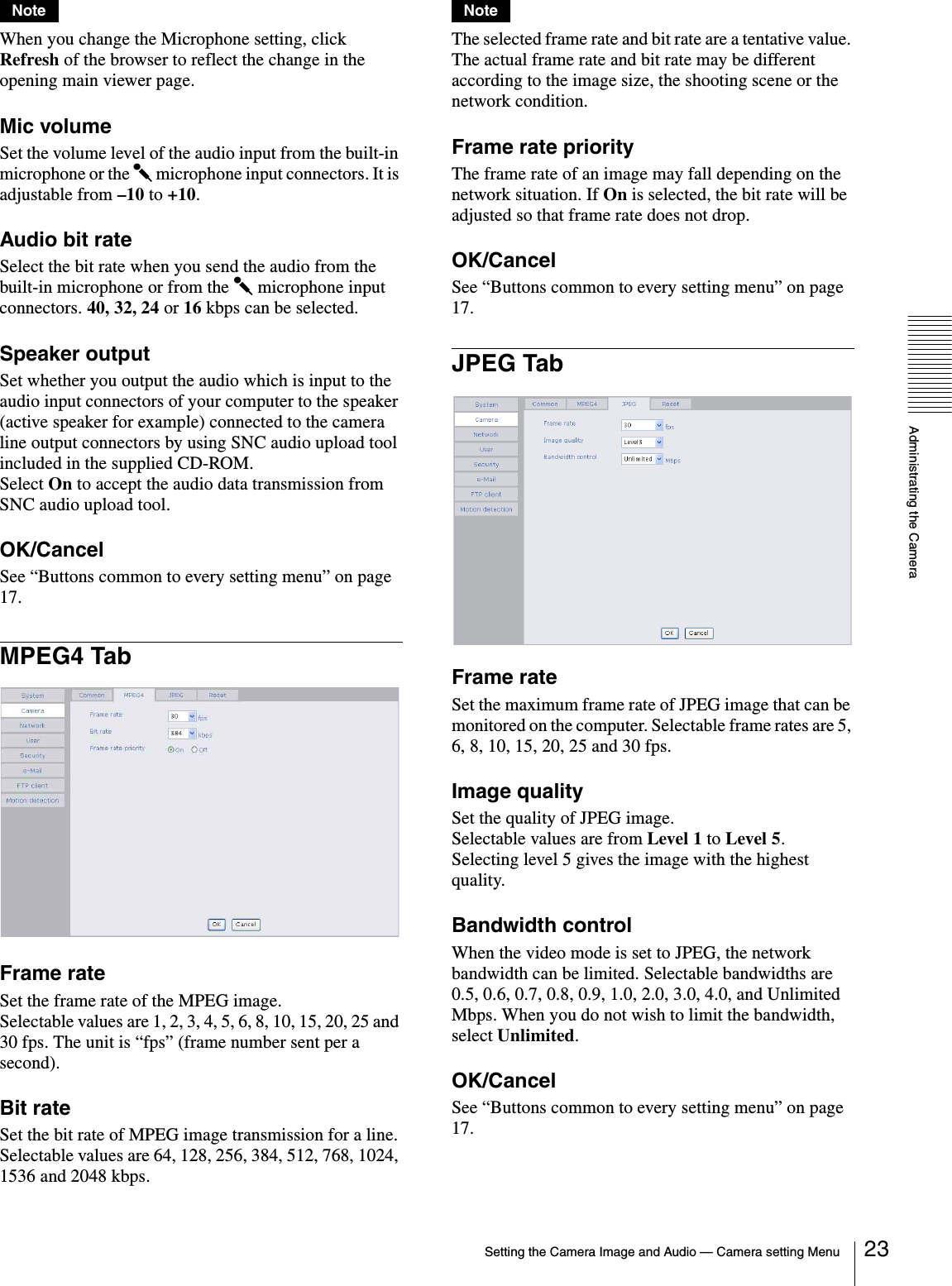
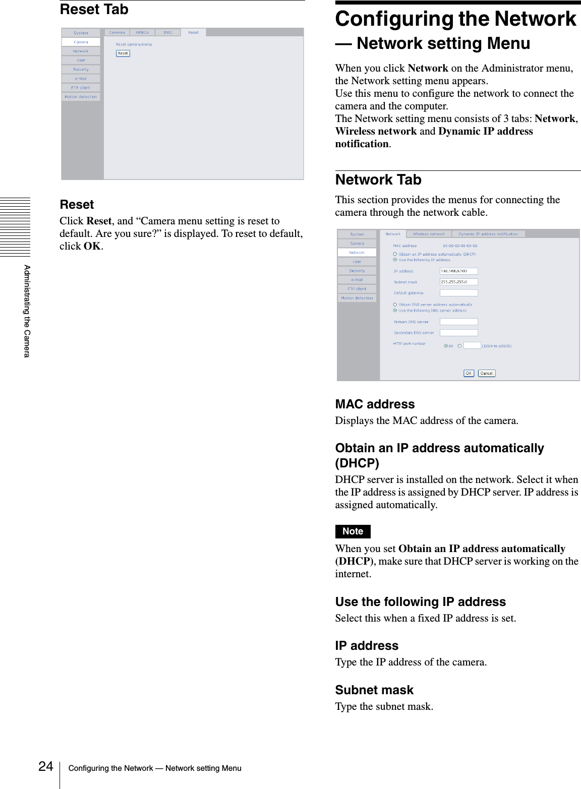
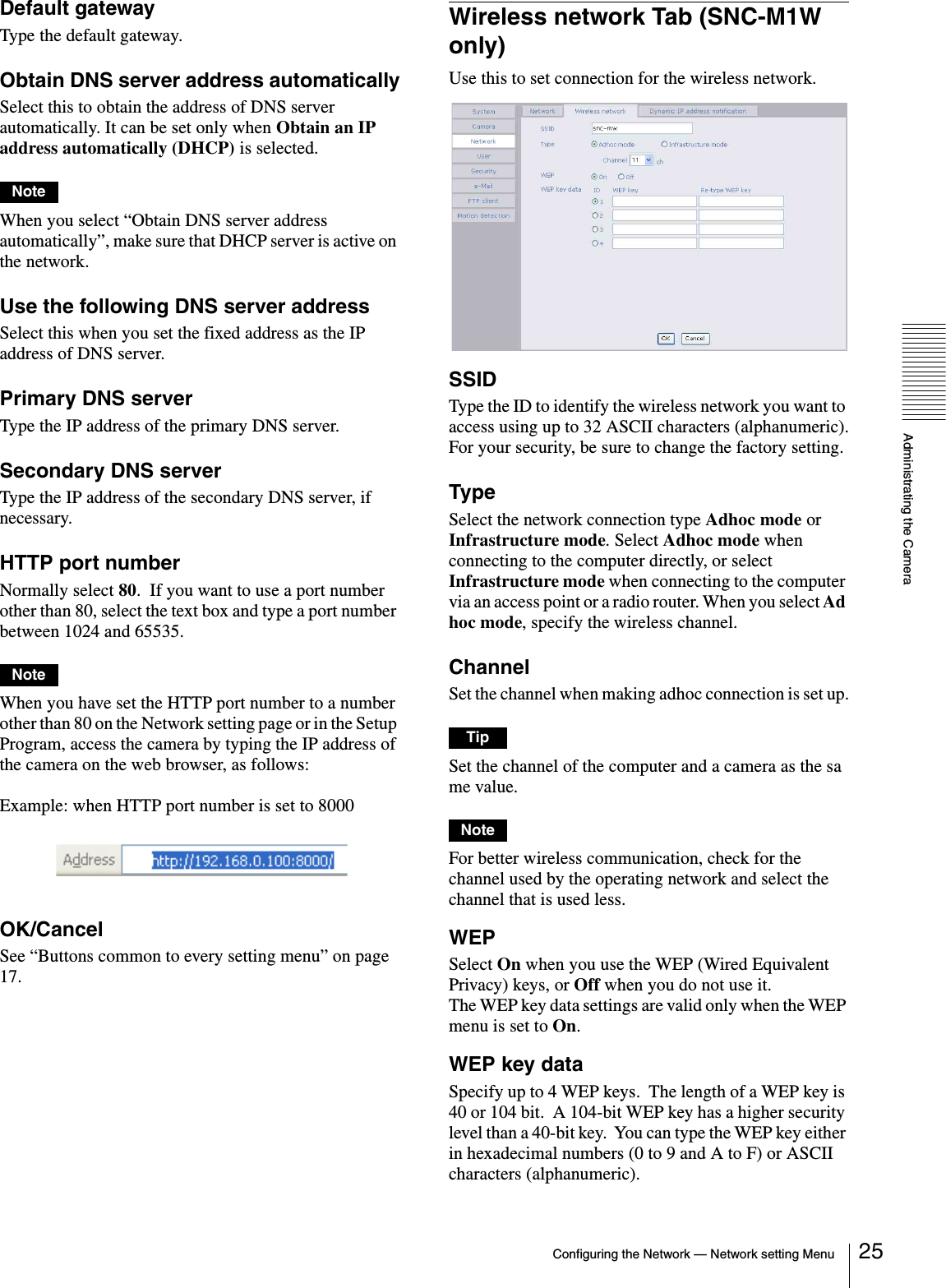
![Administrating the CameraConfiguring the Network — Network setting Menu26When the Type menu is set to Infrastructure mode, the WEP key should be the same as that of the access point. When the Type menu is set to Ad hoc mode, the WEP key should be the same as that of the communication client.Notes• To activate the wireless connection, unplug the network cable and turn on the camera.• The wireless connection and the wired connection using the network cable cannot be used simultaneously.Dynamic IP address notification Tab — Notifying the IP AddressWhen the DHCP setting is set to On on the Network tab, you can send notification of the completion of the network settings using the SMTP or HTTP protocol.e-mail (SMTP) notificationSelect On to send an E-mail when the DHCP setting is completed.SMTP server nameType the name or IP address of the SMTP server you want to use for sending an E-mail, up to 64 characters.AuthenticationSelect the authentication required when you send an e-Mail.None: Select when no authentication is necessary when an e-mail is sent.SMTP authentication: Select when authentication is necessary when an e-mail is sent.POP before SMTP: Select when POP before SMTP is necessary when an e-mail is sent.POP server nameIt is necessary when the POP before SMTP is selected in Authentication.Type the POP (receiving mail) server name up to 64 characters. Or type the IP address of the POP server. This setting is necessary when the SMTP server which sends e-mails performs authentication using the POP user account.User name, PasswordType the user name and Password of the user who has the mail account. This setting is necessary when the SMTP server which sends e-mails performs authentication.Recipient e-Mail addressType the recipient e-Mail address up to 64 characters. You can specify only one recipient e-Mail address.Administrator e-Mail addressType the e-Mail address of the camera administrator, up to 64 characters. This is used as the reply address or the address for a system mail from the mail server.SubjectType the subject/title of the e-Mail up to 64 characters.MessageType the text of the e-Mail up to 384 characters. You can describe the information of the acquired IP address, etc. using the special tags mentioned below.HTTP notificationSelect On to output a command to the HTTP server when the DHCP setting is completed. Using this function, you can configure a useful system, for example, to view the access log stored in the HTTP server or start an external CGI program.URLSpecify the URL to send HTTP commands, up to 256 characters. The URL is normally composed as follows:http://ip_address[:port]/path?parameterip_address: Type the IP address or host name of the host to which you want to connect.:port: Specify the port number to which you want to connect. If you want to use the well-known port number 80, you do not need to input this value.path: Type the command name.parameter: Type the command parameter if necessary. You can use the special tags mentioned below for the parameters.](https://usermanual.wiki/Sony-Group/SNCM1W/User-Guide-491764-Page-26.png)