Sony Group WRT807A66 UHF Synthesized Wireless Microphone User Manual WRT807A 11
Sony Corporation UHF Synthesized Wireless Microphone WRT807A 11
Operating Instruction

3-866-377-11 (1)
WRT-807A
UHF Synthesized
Wireless Microphone
Operating Instructions
Manual de instrucciones
Mode d’emploi
Wireless Channel Lists
Listas de canales inalámbricos
Listes des canaux sans fil
1999 by Sony Corporation [U64] [U66] [U68]
US
EN
FR

Owner’s Record
The model and serial numbers are located at the rear of the
unit. Record the serial number in the space provided below.
Refer to these numbers whenever you call upon your Sony
dealer regarding this product.
Model No. WRT-807A Serial No.
Notice for customers in the U.S.A.
Use of Sony wireless devices is regulated by the Federal
Communications Commission as described in Part 74
subpart H of the FCC regulations and users authorized
thereby are required to obtain an appropriate licence.
You are cautioned that any changes or modifications not
expressly approved in this manual could void your authority
to operate this equipment.
Notice for customers in Canada:
Use of Sony wireless devices is regulated by the Industry
Canada as described in their Radio Standard Specification
RSS-123.
A licence is normally required. The local district office of
Industry Canada should therefore be contacted. When the
operation of the device is within the broadcast band, the
licence is issued on no-interference, no-protection basis with
respect to broadcast signals.
Avis pour les clients au Canada:
L’usage des appareils sans-fil Sony est réglé par l’Industrie
Canada comme décrit dans leur Cahier des Normes
Radioélectriques CNR-123. Une licence est normalement
requise. Le bureau de l’Industrie Canada doit être contacté.
Lorsque l’opération de l’appareil est dans les limites de la
bande de radiodiffusion, la licence est émanée sur la base
de non-interférence, non-protection avec les signaux de
radiodiffusion.

3
US
Table of Contents
English
English
US
Precautions................................................................ 1
Introduction ............................................................... 2
Features .............................................................2
Parts Identification .................................................... 4
Power Supply ............................................................ 7
Settings ...................................................................... 8
Initiating Setting Mode .....................................8
Changing the Transmitting Channel .................8
Changing the Input Attenuation Setting..........10
Resetting the Accumulated Battery Use
Time Indication .........................................11
Troubleshooting ...................................................... 12
Specifications .......................................................... 14
Error Messages ....................................................... 15
Precautions
• The unit is designed for use in ambient temperature range
of 0°C to 50°C (32°F to 122°F).
• Do not place the unit on or near heat sources, such as
lighting equipment, power amplifiers, or in a place subject
to direct sunlight or excessive moisture. In such places,
the external finish or internal parts of the unit may be
damaged.
• If the unit is used in a very humid or dusty place or in a
place subject to an active gas, clean its surface as well as
the connectors with a dry, soft cloth soon after use.
Lengthy use of the unit in such places or not cleaning it
after its use in such places may shorten its life.
• When cleaning the unit, never use organic solvents such as
thinners or benzine, which will damage the finish of the
unit.
• The unit has been factory adjusted precisely. Do not
tamper with its internal parts or attempt to repair it.
• Do not attempt to recharge an alkaline battery.
• Do not dispose of a battery in fire. Do not disassemble or
short-cirtuit a battery.
• Make sure to use an L6 (size-AA) alkaline battery.
• Make sure the poles of the battery match the + and -
markings in the battery holder.
• Remove the battery when the unit will not be used for a
long period of time.

4
US
Introduction
The WRT-807A is a UHF-synthesized wireless microphone
for use in a 800-MHz band UHF-synthesized wireless
microphone system.
The WRT-807A operates in conjunction with the WRR-
800A/801A/802A/805A, MB-806A UHF Synthesized Tuner
for vocal concentration.
The WRT-807A can be also used with existing Sony
wireless microphone systems consisting of the WRT-810A/
820A/822A/830A UHF Synthesized Transmitter and WRR-
810A/820A/840A/850A, MB-806A UHF Synthesized
Tuner.
The microphone/transmitter and tuners of the wireless
microphone system are classified by frequency band.
A 12 MHz frequency band (or two consecutive-numbered
TV channels, such as 68 and 69 of the U68 model) is
assigned to each microphone/transmitter and tuner model.
In building up a UHF wireless microphone system, be sure
to combine a microphone/transmitter and a tuner having the
same TV channel number.
For the selectable wireless channels and frequencies, see
“Wireless Channel Lists” on page L-1.
Features
Phase Locked Loop (PLL) synthesized system
The WRT-807A features a refined phase locked loop (PLL)
synthesizer circuit.
POWER switch with holding function
The POWER switch can be locked in the ON position to
protect against accidental power cut-offs.
Low-battery notification on tuner
When the microphone battery is low, the microphone sends
a warning to the WRR-800A/801A/802A/805A/850A, MB-
806A in the form of “Battery status information.”
This information is sent to the WRR-800A/801A/802A/
805A/850A, MB-806A about one hour before the battery
goes dead to allow the battery to be safely replaced.
When the WRR-800A/801A/802A/805A/850A, MB-806A
receives this information, the LED and the LCD on tuner
panel start to flash.
Powered by readily available battery type
The built-in, high-efficiency DC-DC converter provides
about five hours of continuous and stable operation with just
a single LR6 (size-AA) alkaline battery.

5
US
LCD readout of various information
The microphones LCD shows the current channel number,
frequency, input attenuation setting, and residual battery
power.
The accumulated battery use time is also indicated (in one-
minute increments) to allow precise monitoring of battery
use.
Automatic saving of channel and input attenuation
settings
All channel and input attenuation settings are automatically
saved when the microphone is turned off (and are
maintained even when the battery is removed), thus
eliminating the need to make the same settings again the
next time you use the microphone.
Highly reliable electronic attenuator
Adjustable in a range of 0 dB to 21 dB in 3-dB steps, the
built-in input level attenuator reduces signal distortion
during the input of excessively strong audio signals.
Tone signal-incorporated RF carrier signal
The microphone transmits an RF carrier signal that
incorporates a tone signal to enable any tuner with a tone
squelch circuit to pick out only the target audio signal.
Wide dynamic range and low noise
The microphones compander (compressor/expander) system
enables transmission over a wide dynamic range with
minimum noise.
Notes on operation
• When operating two or more microphones, keep the
microphones separated from each other by a distance of at
least 30 cm (1 foot.).
• Keep microphones at least 3 meters (10 feet) away from
the receiving antenna.
6
US
6
5
4
7
2
3
1
8
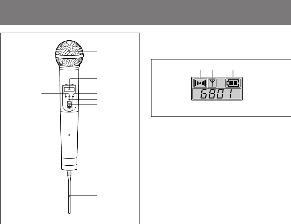
Parts Identification
1 Wind screen
Protects against noise caused by wind.
2 Liquid-crystal display
A AF (audio input) indication
Lights whenever an audio signal stronger than the reference
level is received.
B RF (antenna output) indication
Lights during signal transmission from the antenna.
C BATT (battery) indication
Shows the battery condition.
See “Battery indication” on page 7.
Display example
for U68 model
AB
D
C
AF RF BATT
7
US
+
SET
–
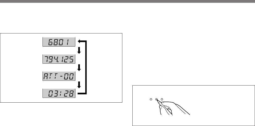
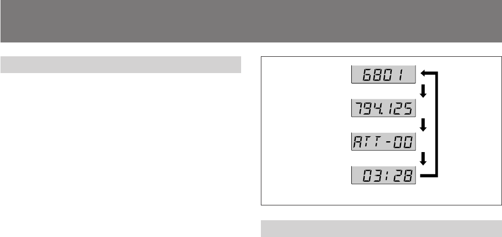
D CH (channel) indication
Displays the transmission channel.
Each time you press the SET button in Transmit mode, the
channel indication changes as follows.
Transmission channel: The current transmission channel
setting.
Transmission frequency: The current transmission
frequency setting.
Attenuation: The input attenuation setting in decibels.
Can be set within a range of 0 dB to 21 dB in 3-dB
steps.
Accumulated battery use time: The accumulated time of
battery use (in 1-minute increments).
Transmission
channel
To adjust these parameters, see “Changing the
Transmission Channel” on page 5, “Changing the Input
Attenuation Setting” on page 10 or “Resetting the
Accumulated Battery Use Time Indication” on page 11.
3 SET button
In Transmit mode, press this button to change the indicated
items in the lower half of the liquid-crystal display.
To change to Setting mode, turn the POWER switch to ON
while holding this button down. Then press this button to
select the items to be indicated.
How to press the SET and +/– buttons
For details on Setting mode, see “Settings” on page 8.
Press the button with a
ballpoint pen or similar item.
Transmission
frequency
Attenuation level
Accumulated
battery use time
Press SET
button.
Display example
for U68 model
8
US
ON
HOLD
.
ON
HOLD
.
4 POWER indicator
Lights when the microphone is on.
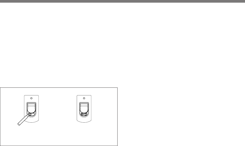
5 POWER switch
Turns the microphone ON or OFF.
When you set this switch to ON without holding down any
other button, the microphone enters Transmit mode, and the
signal of the selected channel is transmitted.
The HOLD switch appears when the POWER switch is set
to ON.
Set the HOLD switch to the lock position to prevent an
accidental power cut-off during microphone operation.
Locking the POWER switch
Slide the HOLD switch to the
right with a ballpoint pen or
similar item.
6 Antenna
7 Battery holder
Insert the battery here.
For details on inserting the battery, see “Power Supply” on
page 7.
8 + (+ selection) / – (– selection/reset) buttons
In Setting mode, use these buttons to select the transmission
channel and attenuation level, and use the – button to reset
the accumulated battery use time indication to 00:00.
For details on Setting mode, see “Settings” on page 8.
A yellow mark appears
when the switch is in the
hold position.
/
Parts Identification
9
US
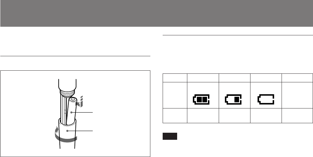
1234
BATT
indication
Lights Lights Flashes Goes off
Battery
condition Good Less than
half-charge Almost
exhausted Completely
exhausted
2
1,3
E
e
Power Supply
The microphone can operate on one LR6 (size AA) alkaline
battery continuously for about 5 hours at 25 ºC (77ºF).
Inserting the battery
1Turn the grip in the direction of the arrow to open the
battery holder.
2Match the battery to the polarity markings and insert it
into the battery holder.
3Close the battery holder and lock the grip by turning it
in the opposite direction of the arrow.
Battery indication
When you turn the power on, the battery condition is
indicated by the BATT indication in the liquid-crystal
display.
Note
The indication may be incorrect if the battery was not new
when inserted. If you plan to use the microphone for a long
period, replace the battery with a new one.
10
US
Channel selection
mode
Freqency selection
mode
Attenuator adjustment
mode
Accumulated time
indication reset mode
Press the
SET button.
Settings
Entering Setting Mode
Enter Setting mode to change the transmission channel, the
transmission frequency and the attenuation level, or to reset
the accumulated battery use time indication.
To enter Setting mode
While holding down the SET button, turn the POWER
switch to ON.
Hold the SET button down until an indication appears on the
liquid-crystal display.
The microphone enters Setting mode and the indication
before the microphone was previously turned OFF flashes
on the liquid-crystal display.
Pressing the SET button cycles the modes in the order of
Channel selection mode, Frequency selection mode (page
8), Attenuator adjustment mode (page 10) and Accumulated
time indication reset mode (see page 11).
Changing the Transmission Channel
The transmission channel can be selected through either the
channel number or the frequency.
1Set the microphone to Setting mode.
If the channel number (or frequency) indication does not
appear, press the SET button until the channel number
(or frequency) indication appears.
Display example
for U68 model
11
US
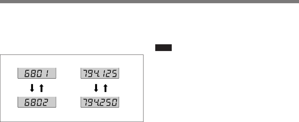
Channel selection mode Freqency selection mode
+ button – button + button – button
Display example for U68 model
2Press the + or – button to select the channel number (or
frequency).
Pressing the + button cycles the indication in the order
shown in the tables in Overview of “Wireless Channel
Lists” on page L-1. Pressing the – button cycles the
indications in the opposite direction.
Hold down the button to change the channel number (or
frequency) quickly.
3When the desired channel number (or frequency)
appears, turn the POWER switch to OFF to release
Setting mode, or press the SET button to continue
operations in Setting mode.
The next time you turn on the microphone (by turning the
POWER switch to ON), the microphone will enter Transmit
mode with the selected channel number (or frequency).
Notes
• The microphone cannot transmit in Setting mode.
• Make sure that the channel selected on the microphone is
the same as that selected on the tuner being used in the
same system.
• Depending on the noise or interference conditions, all
selectable channels may not be usable. If necessary, you
can determine which channels are usable by cycling the
channel selection through a number of channels on the
tuner with the microphone set to OFF. Those channels for
which the RF indicator on the tuner does not light are
usable.
• The microphone may not operate correctly if it is turned
on immediately after being turned off in Setting mode.
Wait for a few seconds before turning the power on again.
12
US
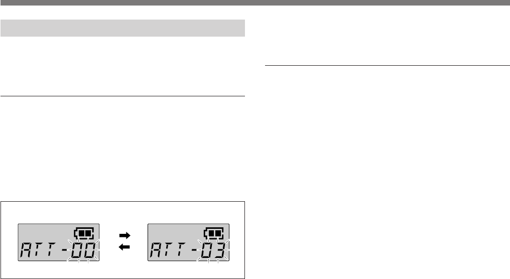
+ button
AF RF BATT AF RF BATT
– button
Changing the Input Attenuation Setting
The input attenuation setting can be changed within a range
of 0 dB to 21 dB (in 3-dB steps) in either Setting mode or
Transmit mode.
Changing the input attenuation in Setting
mode
1Set the microphone to Setting mode.
2If the attenuation level is not displayed, press the SET
button until it appears.
3Press the + or – button to change the attenuation setting.
Hold down the button to change the level quickly.
4Once the desired level appears, turn the POWER switch
to OFF to release Setting mode, or press the SET button
to continue operations in Setting mode.
The next time you turn on the microphone (by turning the
POWER switch to ON), the microphone enter Transmit
mode with the selected attenuation setting.
Changing the input attenuation in Transmit
mode
You can also change the input attenuation setting while
transmitting in Transmit mode.
1If the attenuation level is not displayed, press the SET
button until it appears.
2Press the + or – button to change the attenuation setting.
Setting
13
US
AF RF BATT AF RF BATT
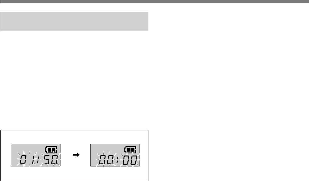
– button
Resetting the Accumulated Battery Use
Time Indication
The accumulated battery use time is the total time (in hours
and minutes) the battery has been used. It is recorded
whenever the WRT-807A is on.
Reset the indication to 00:00 whenever you replace the
battery.
1Set the microphone to Setting mode.
2If the accumulated battery use time is not displayed,
press the SET button until it appears.
3Press the – button.
The indication resets to 00:00.
Press the + button while the 00:00 indication is on to go
back to previous value.
4Turn the POWER switch to OFF to release Setting
mode.

14
US
Troubleshooting
If you have any problem using this unit, use the following checklist. Should any problem persist, consult your Sony dealer.
Symptom Meaning/Remedy
The microphone does not turn on. • The + and – poles of the battery do not match those of the battery compartment. b Insert the
battery with the poles correctly matched.
• The battery is exhausted. b Replace the battery with new one.
• The battery terminals in the microphone are dirty. b Clean the + and – terminals with a cotton
swab.
The battery runs down quickly. • The battery is exhausted. b Replace the battery with new one.
• A manganese battery is being used. b Use an alkaline battery. The battery life of a manganese
battery is less than half that of an alkaline battery.
• The microphone is being used under cold conditions. b The battery runs down quickly under cold
conditions.
The microphone cannot be turned
off. The HOLD switch is in locked position. b Change the HOLD switch to the unlocked position.
The channel cannot be changed. An attempt was made to change the channel by pressing the SET button only. b Turn the
microphone off, then turn the microphone on again while holding down the SET button. Then
change the channel with the + and – buttons.
There is no sound. • The indication on the LCD is flashing. b The microphone is in channel setting mode. Turn the
power off, then on again.
• The channel setting on the microphone is different from that on the tuner. b Use the same channel
setting for both the microphone and tuner.
• The AF or RF indicator does not turn on. b Confirm that the microphone and tuner are both turned
on.

15
US
The sound is weak. • The attenuation level setting is too high. b The output level is low. Press the – button in attenuation
level setting mode to lower the attenuation level.
• The volume on the amplifier, mixer or tuner is low. b Adjust the volume.
There is distortion in the sound. The attenuation level setting is too low. b The input level is extremely high. Press the + button in
attenuation level setting mode to raise the attenuation level.
There is sound interruption or
noise. • The receiver's antenna is incorrectly connected. b Connect the antenna correctly according to the
operation manual of the tuner or antenna divider.
• The antenna divider is turned off. b Turn the antenna divider on. It is possible for the tuner to
receive signals even when the antenna divider is turned off, but sound interruption or noise may
occur.
• The RF indicator lights even when the tuner is off. b Jammed transmissions are being received.
Determine which channels are usable (i.e., channels for which the RF indicator on the tuner does
not light) and set the tuner and microphone to the same usable channel.
• Two or more microphones are set to the same channel. b Make sure no two microphones are set to
the same channel. Set each microphone to a different channel.
Symptom Meaning/Remedy

16
US
. . . . . . . . . . . . . . . . . . . . . . . . . . . . . . . . . . . . . . . . . . . . . . . . . . . . . . . . . . . . . . . . . . . . . . . . . . . . . . . . . . . . . . . . . . . . . . . . . . . . . . . . . . . . . . . . . . . . . . . . . . . . . . .
1) 0 dBSPL = 2 × 10⁻⁵ Pa
Specifications
Power section
Power requirements 1.5 V DC
(one LR6/size AA alkaline
battery)
Battery life Approx. 5 hours at 25°C or
77°F, with Sony LR6 alkaline
battery
General
Operating temperature 0°C to +50°C (32°F to 122°F)
Storage temperature –30°C to +60°C (–22°F to
+140°F)
Dimensions 51 × 238 mm (diameter/length)
not including antenna
(2-1/8 × 9-3/8 inches)
Mass Approx. 440 g (15.5 oz)
including battery
Supplied accessory
Operating Instructions (1)
Microphone holder (1)
Screw adaptor PF 1/2 to NS 5/8 (1)
Design and specifications are subject to change without
notice.
Transmitter and modulator section
Oscillator Crystal controlled PLL
synthesizer
Type of emission F3E
Carrier frequencies
U64 model: 770.125 to 781.875 MHz
(TV channels 64 and 65)
U66 model: 782.125 to 793.875 MHz
(TV channels 66 and 67)
U68 model: 794.125 to 805.875 MHz
(TV channels 68 and 69)
RF power output 10 mW (50-ohm load)
Tone signal 32.768 kHz
Battery condition signal 32.782 kHz
Type of antenna 1/4 -wavelength wire
Audio section
Microphone type uni-directional dynamic
microphone
Pre-emphasis 50 µs
Deviation ±5 kHz (94 dBSPL1), 1 kHz input)
Frequency response 50 to 15,000 Hz
Signal-to-noise ratio 57 dB or more (A-weighted,
modulation frequency 1 kHz,
with ±5 kHz deviation at WRR-
800A/801A)
Audio attenuator 0 to 21 dB, variable in 3-dB
steps
Input level 151 dBSPL
(at audio attenuator 21 dB)
17
US
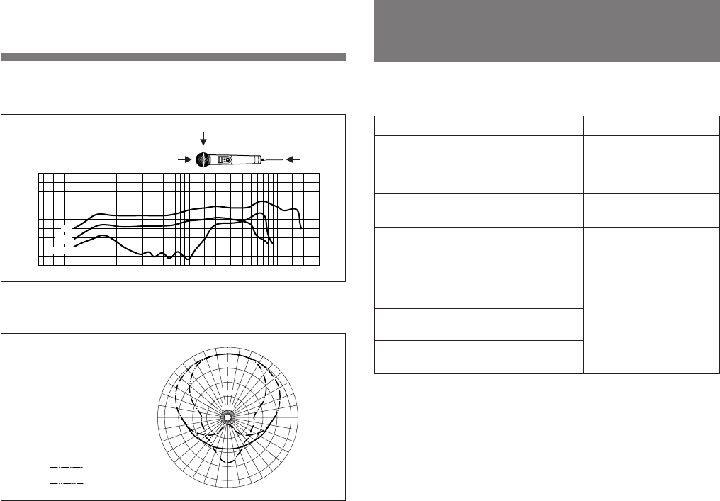
Standard frequency response
Standard directivity response
Error Messages
When a problem occurs, one of the following error
messages may appear on the display.
20
dB
10
0
–10
–20
–30 20 50 100 200 500 1k 2k 5k 10k 20k Hz
0°
90°
180°
0°180°
90°
100 Hz
1 kHz
6 kHz
0°
30°30°
60°60°
90°90°
120°120°
150°150°
180°
0dB
–5
–10
–15
–20
Message Contents Measures
Error 11 An error occurred in
backup memory data. The data was initialized.
Set the transmitting
channel and the input
attenuation again.
Error 21 The PLL synthesized
circuit is in trouble. Contact your Sony
dealer.
Error 31 The battery voltage
exceeds the allowable
value.
Use the specified battery.
Error 41 Defect of an internal
circuit.
Error 51 Defect of the A/D
converter circuit.
Error 61 Defect of an internal
circuit.
Contact your Sony
dealer.

Sony Corporation Printed in Japan