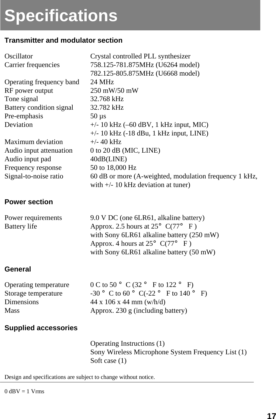
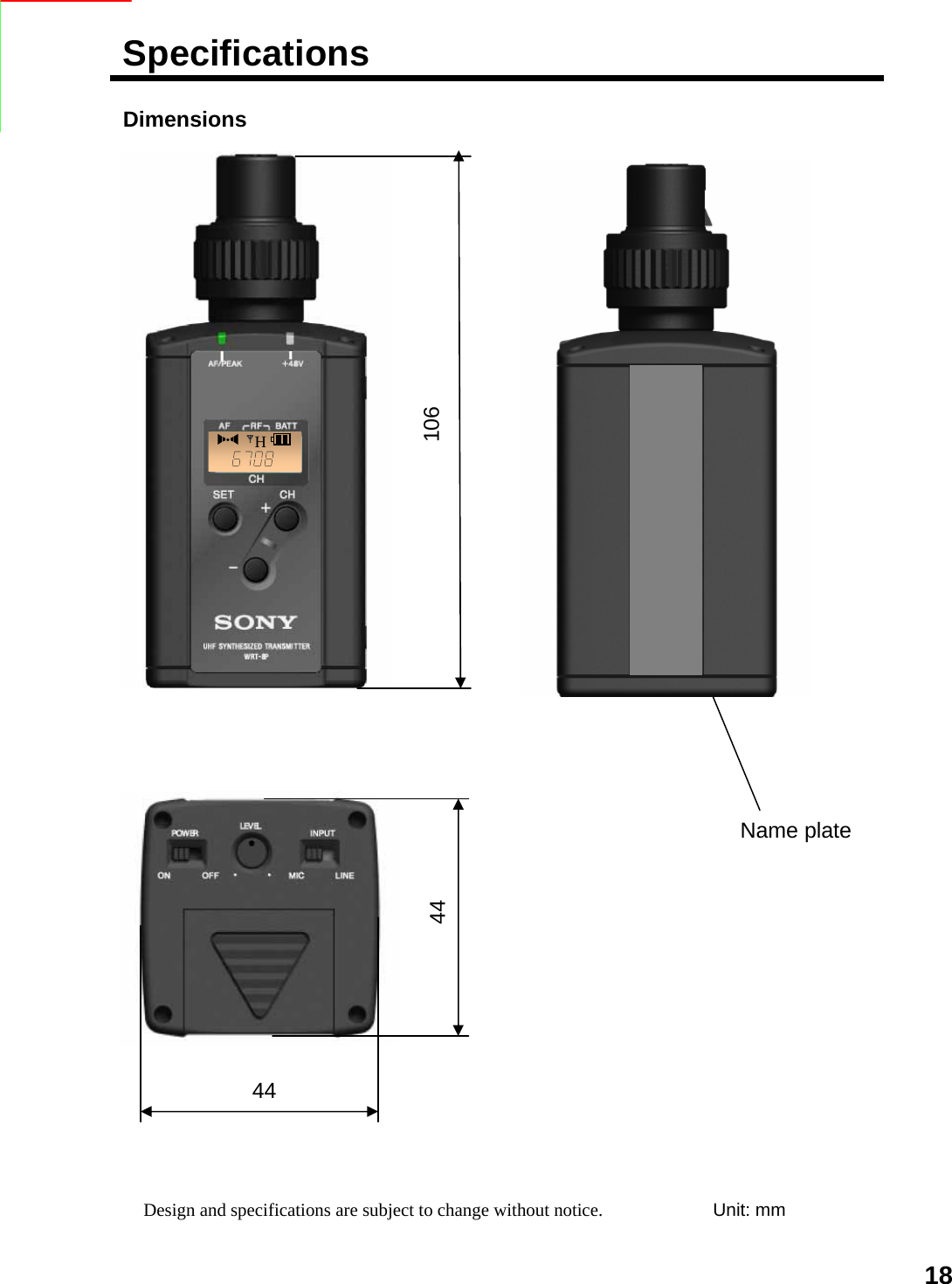
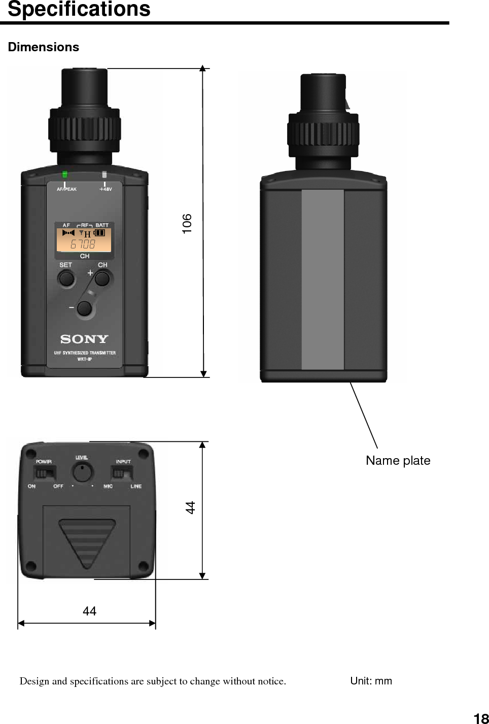
Sony Group WRT8P UHF Synthesized Transmitter User Manual 1

Sony Corporation UHF Synthesized Transmitter 1

Users Manual

DRAFTUHF Synthesized TransmitterOperating Instructions Before operating the unit, please read this manual thoroughly and retain it for future reference.WRT-8P©2006 Sony Corporation
Owner’s RecordThe model number plate is located on the side and the serial number is located inside the battery compartment. Record the model and serial numbers in the space provided below. Refer to these numbers whenever you call upon your Sony dealer regarding this product. Model No. WRT-8P Serial No. _____________________Notice for customers in the U.S.A.Use of Sony wireless devices is regulated by the Federal Communications Commission as described in Part 74 subpart H of the FCC regulations and users authorized thereby are required to obtain an appropriate license. You are cautioned that any changes or modifications not expressly approved in this manual could void your authority to operate this equipment. IMPORTANT NOTE: To comply with the FCC RF exposure compliance requirements, no change to the antenna or the device is permitted. Any change to the antenna or the device could result in the device exceeding the RF exposure requirements and void user’s authority to operate this device. This equipment complies with FCC radiation exposure limits set forth for an uncontrolled environment. This equipment should be installed and operated with minimum distance 20cm between the radiator and body (excluding extremities: hands, wrists and feet).FCC Radiation Exposure Statement:The available scientific evidence does not show that any health problems are associated with using low power wireless devices. There is no proof, however, that these low power wireless devices are absolutely safe. Low power Wireless devices emit low levels of radio frequency energy (RF) in the microwave range while being used.  Whereas high levels of RF can produce health effects (by heating tissue), exposure to low level RF that does not produce heating effects causes no known adverse health effects. Many studies of low level RF exposures have not found any biological effects. Some studies have suggested that some biological effects might occur, but such findings have not been confirmed by additional research. The WRT-8P has been tested and found to comply with the Federal Communications Commission (FCC) guidelines on radio frequency energy (RF) exposures. 2
Notice for customers in Canada:Use of Sony wireless devices is regulated by the Industry Canada as described in their Radio Standard Specification RSS-123. A license is normally required. The local district office of Industry Canada should therefore be contacted. When the operation of the device is within the broadcast band, the license is issued on no-interference, no-protection basis with respect to broadcast signals. Operation of this device is subject to the following two conditions: (1) this device may not cause interference, and (2) this device must accept any interference, including interference that may cause undesired operation of the device. The term “IC:” before the radio certification number only signifies that Industry Canada technical specifications were met.IC Exposure of Humans to RF FieldsThe installer of this radio equipment must ensure that the antenna is located or pointed such that it does not emit RF field in excess of Health Canada limits for the general population; consult Safety Code 6, obtainable from Health Canada’s website www.hc-sc.gc.ca/rpb”3
Table of Contents•Overview (Features)  ---- 5•Precautions ---- 5•Parts Identifications ---- 6•Power Supply ---- 9•Settings ---- 10Initialing setting modeSetting the transmission channelSetting the attenuation level of the audio inputSetting the RF output powerSetting the +48V power supply•Attachment and installation procedures ---- 13•Notes on microphone system operations ---- 14•System Configurations ---- 15•Error Messages ---- 16•Specifications ---- 174
OverviewThe WRT-8P is a plug-on transmitter for a UHF synthesized wireless microphone system to be used for broadcast or movie production purpose. This transmitter is suitable for Electronic News gathering (ENG) and Electronic Field Production (EFP).The microphone/transmitter and tuner of the wireless microphone system are classified by frequency band.A 24-MHz frequency band is assigned to each microphone/transmitter and tuner model. In building a UHF wireless microphone system, be sure to combine a microphone/transmitter and a tuner having the same wireless channel (frequency).FeaturesThe features of the WRT-8P are:•Converts a wired microphone to a wireless microphone via an XLR-type connector.•Compact and lightweight metal body provides high durability and good balanced handling.•250 mW high RF output power for stable long-distance transmission.•Selectable RF output power: 250 mW/50 mW.•+48 V power supply capability.•Switchable input level: MIC/LINE•Attenuator function allows adjustment of the audio-input level.•A backlit LCD provides extensive information.•Optimized balance when combined with the F-112 dynamic microphone.Precautions• The unit is designed for use in ambient temperature range of 0°C to 50°C (32°F to 122°F).• Do not place the unit on or near heat sources, such as lighting equipment, power amplifiers, or in a place subject to direct sunlight or excessive moisture. In such places, the external finish or internal parts of the unit may be damaged.• If the unit is used in a very humid or dusty place or in a place subject to expose to an active or corrosive gas, clean its surface as well as the connectors with a dry, soft cloth soon after use.• Lengthy use of the unit in such places or not cleaning it after its use in such places may shorten its life.• When cleaning the unit, never use organic solvents such as thinners or benzine, which will damage the finish of the unit.• The unit has been factory adjusted precisely. Do not tamper with its internal parts or attempt to repair it.5
Parts IdentificationAudio input connector28913567AF/PEAK indicator(Audio input LEVEL)HDisplay sectionSET button6MIC / LINE selectorPOWER switch+48V indicator104- , + buttonsAF LEVEL controlBattery lid
Parts identificationAudio input connectorConnect the following Sony’s  microphones: F112, ECM-678, ECM-674 or a line output cable from Sony’s portable mixer DMX-P01.When connecting a microphone or a cable to the unit, be sure to turn the unit off.SET buttonIn Transmitting mode, press this button to change the indicated items in the lower half of the LCD display.The SET button is also used to enter the Setting mode and select the item to be set.+ / – buttonsIn setting mode, select the transmission channel, frequency and RF output power setting using either of these buttons, or set/reset the +48V power supply.POWER switchTurns the transmitter ON or OFF.Be sure to connect a microphone or a cable before turning the power ON.AF LEVEL controlAdjusts the audio level from the audio input connector.3245CautionNote6A  AF (audio input) indicationAppears whenever an audio signal stronger than the reference level is received.B  RF (antenna output) indicationAppears during signal transmission from the antenna.C  RF power indicationShows the RF output power setting.See “Changing the RF Output Power.”D  BATT (battery) indicationShows the battery condition.See “Battery indication” in “Power Supply” section.E  CH (channel) indicationShows transmitting channel.Each time you press the SET button in Transmitting mode, the channel indication changes as follows.Display section17
Parts identificationAF LEVEL controlAdjusts the audio input level from the audio input connector .MIC/LINE select switchSet this switch to MIC when amicrophone is connected to the audioinput connector; set it to LINE whenan audio mixer, etc. is connected to theaudio input connector.For details, on the use of this switch, see “Adjusting the Audio Input Level.”Before changing to the MIC position from LINE position, be sure to turn the unit off to avoid a noise when the +48V power supply is turned on, or adding high output level audio signal. AF/PEAK indicatorThe green or red color indicates the strength of the audio input signal level.+48V indicatorThe indicator shows the +48V power supply is enable when MIC/LINE switch is in MIC position.Battery lidSlide the battery lid to release the lock and open the battery compartment.869710Note8
Power SupplyBattery indicationWhen you turn the power on, the battery condition is shown by the BATT indication in the display section.When the indication in column 4 starts to flash, replace the batteries with new one. Be sure to check the expiration date printed on the new battery before using it.The indicated battery condition may not be correct if the battery was not new when installed. If you plan to use the component for a long period, it is recommended that you replace the battery with brand new one.Notes on batteryBattery may leak or explode if mistreated. Be sure to follow these instructions.• Be sure to install the battery with the correct polarity.• The battery are not rechargeable.• When not using the component for a long period of time, remove the battery to avoid leakage. If the battery dose leak, clean all leakage from the battery compartment and the component. Leakage left in the compartment and the component may cause poor battery contact. If there seems to be poor battery contact, consult your Sony dealer.NOTEWRT-8P can be powered by one 6LR61 (9V) alkaline battery for about five hours of continuous operation (at 25°C, 77°F) . The battery condition Indication are given below:Inserting the battery1Slide the battery lid to release the lock and open the battery compartment.2Align one new 6LR61 (9V) alkaline battery with the polarity markings and insert them into the battery compartment, and then close the cover.9
SettingsNOTE Initiating Setting ModeIn Setting mode, you can change the transmission channel/frequency and the RF output power level, or +48V power supply.To Enter Setting ModeWhile holding down the SET button, set the POWER switch to ON.The transmitter enters Setting mode and the indication before the transmitter was previously turned OFF flashes on the display section.Each time you press the SET button, the setting items are cyclically switched as shown below.• The transmitter cannot transmit in Setting mode.• Make sure that the channel selected on the transmitter is the same as that selected on the tuner being used in the same system.• Depending on the noise or interference conditions, all selectable channels may not be usable. If necessary, you can determine which channels are usable by cycling the channel selection through a number of channels on the tuner with the unit set to OFF. Those channels for which the RF indicator on the tuner does not light are usable.• If there is a TV broadcasting station near by, do not use the station’s channel.• The transmitter may not operate correctly if it is turned on immediately after being turned off in Setting mode. Wait for a few seconds before turning the power on again.• The channel numbers and frequencies of your transmitter are shown on the “Sony Wireless Microphone System Frequency List” supplied with the manual.MIC or LINE10
SettingsChanging the TransmittingChannelChanging the RF OutputPowerThe transmitting channel can be selected through either the channel number or the frequency.1 Set the transmitter to Setting mode.2If the channel number (or frequency) indication does not appear, press the SET button until the channel number (or frequency) indication appears.3 Press the + or – button to select the channel number (or frequency).Pressing the + button cycles the indication in the order shown in the tables in the “Sony Wireless Microphone System Frequency List”supplied with the manual. Pressing the –button cycles the indications in the opposite direction.Hold down the button to change the channel number (or frequency) quickly.You can select the RF output power from the levels of H (250mW) and L (50 mW) in Setting mode. 1 Set the transmitter to Setting mode.2 Press the SET button until the RF output power indication appears on the display.3 Press the + or – button to select the setting: H (250mW) or L (50 mW).4 Set the POWER switch to OFF to release Setting mode. Or, press the SET button to continue operations in Setting mode.The next time you turn on the transmitter by setting the POWER switch to ON, the transmitter enters Transmit mode with the selected RF output power.11
SettingsAdjusting the Audio InputLevelSetting the +48V power supplyYou can change the audio input level in a range of  -60 dBV to –40 dBV (when the MIC/LINE selector is at MIC position) or –20 dBV to 0 dBV (when the MIC/LINE selector is at LINE position).1Set the MIC/LINE select switch according to the equipment connected to the audio input connector.When a microphone is connected to this unit, set the selector to MIC position; when a mixer, etc., is connected, set it to LINE position.2Turn the AF LEVEL control so that the AF/PEAK indicator does not light in RED color continuously. Occasional lighting of the AF/PEAK indicator in RED is acceptable.You can set the +48V power supply for the electric condenser microphone in Setting mode.1 Set the transmitter to Setting mode.2 Press the SET button until the “MIC”or “MIC+48” indication appears on the display.3 Press the + button to select the setting “MIC+48”, or press the – button to select the setting “MIC”“MIC+48” shows the +48V power is set, and it is supplied when MIC/LINE switch is set to MIC position in Transmit mode.4 Set the POWER switch to OFF to release Setting mode. Or, press the SET button to continue operations in Setting mode.The next time you turn on the transmitter by setting the POWER switch to ON, the transmitter enters Transmit mode with the selected power supply setting. 12
131 Turn the connector ring left.Attachment and Installation ProceduresAttaching a microphone or a cable Inserting into  the supplied soft caseInsert the WRT-8P into the supplied soft case with the rear side up, and close the flap.2 Insert to the connector of a microphone or a cable plug until the end.3 Turn the connector ring right to fix the latch against a microphone or a cable.Attaching a microphone or a cableTurn the connector ring left to lose the latch.
Notes on microphone system operations• To operate with two or more channels, maintain a distance of at least 30 cm (one ft.) between each pair of transmitters. For details of operation with two or more channels, refer to the Operating Instructions for the WRR-802/805/855/862, or WRU-8N with MB-8N, etc.• Ensure that the tuners set to channels not being used are either turned off or set to the minimum output level.• When powering the transmitter on or off, to keep the noise to a minimum, set the audio output level from the tuner or mixer to a minimum.• Powering the transmitter on without checking the channel selection first may interfere with the operation of other microphones/transmitters, if the current setting is already being used.• To prevent noise generation, set the RF power output to L (50 mW) when multiple channels are used simultaneously, and keep the microphones and transmitters at least 6 m (20 feet) away from the antennas when the system is operated using a group which allows selection of up to 8 channels, and at least 12 m (40 feet) away when using a group which allows selection of 9 channels. • When there is a strong interference signal around the microphone system, such as an interference caused by an active handy phone, noise may occur on the microphone system.• Before to be attached or removed the microphone or cable, turn down the volume of the equipment connected to the tuner. Otherwise, noise will be produced.14
System ConfigurationsExample of typical systemPortable mixerDMX-P01MicrophoneF-112Plug-on transmitterWER-8PMicrophoneECM-678ECM-674Portable tunerWRR-855BWRR-861BWRR-862BPortable tunerWRR-861BWRR-862B Portable mixerDMX-P01 CamcorderPDW-530/530P/510/510P15
When a problem occurs, one of the following error message may appear on the display.16
SpecificationsTransmitter and modulator sectionOscillator Crystal controlled PLL synthesizerCarrier frequencies 758.125-781.875MHz (U6264 model)782.125-805.875MHz (U6668 model)Operating frequency band 24 MHzRF power output 250 mW/50 mWTone signal 32.768 kHzBattery condition signal 32.782 kHzPre-emphasis 50 µsDeviation +/- 10 kHz (–60 dBV, 1 kHz input, MIC)+/- 10 kHz (-18 dBu, 1 kHz input, LINE)Maximum deviation +/- 40 kHzAudio input attenuation 0 to 20 dB (MIC, LINE)Audio input pad 40dB(LINE)Frequency response 50 to 18,000 HzSignal-to-noise ratio 60 dB or more (A-weighted, modulation frequency 1 kHz, with +/- 10 kHz deviation at tuner)Power sectionPower requirements 9.0 V DC (one 6LR61, alkaline battery)Battery life Approx. 2.5 hours at 25°C(77°F ) with Sony 6LR61 alkaline battery (250 mW)Approx. 4 hours at 25°C(77°F ) with Sony 6LR61 alkaline battery (50 mW)GeneralOperating temperature 0 C to 50 °C (32 °F to 122 °F)Storage temperature -30 °C to 60 °C(-22 °F to 140 °F)Dimensions 44 x 106 x 44 mm (w/h/d)Mass Approx. 230 g (including battery)Supplied accessoriesOperating Instructions (1)Sony Wireless Microphone System Frequency List (1)Soft case (1)Design and specifications are subject to change without notice.0 dBV = 1 Vrms17
SpecificationsDimensionsH10644Name plate44SONY R            Model. WRT-8PUHF SYNTHESIZED TRANSMITTER5    Unit: mmDesign and specifications are subject to change without notice.18
Printed in Japan19

Navigation menu