Sony 6220502-BV Transmitter module for mobile applications User Manual Integrators
Sony Mobile Communications Inc Transmitter module for mobile applications Integrators
Sony >
Contents
- 1. Exhibit 08 Manual Statements
- 2. Integrators User Manual
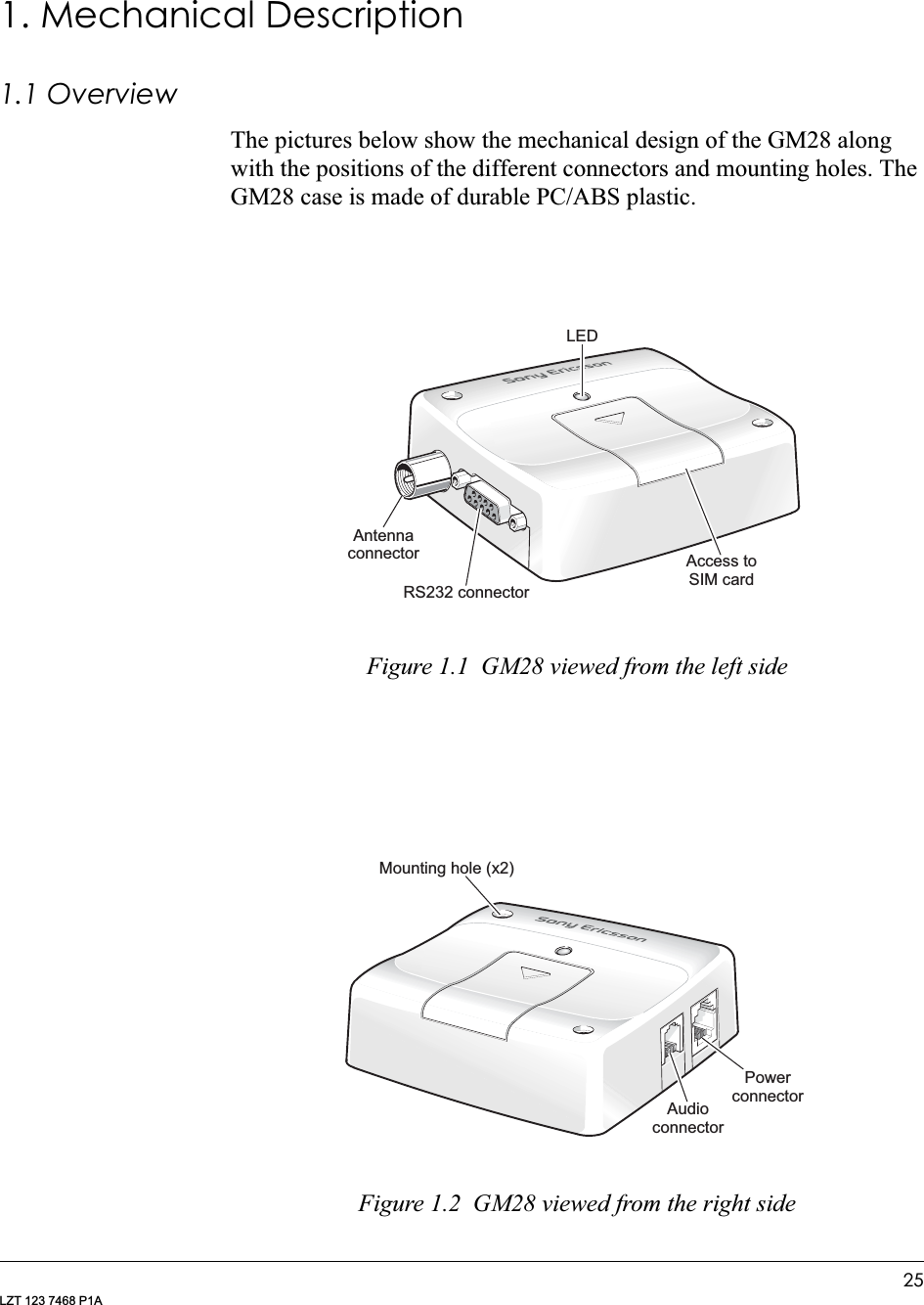
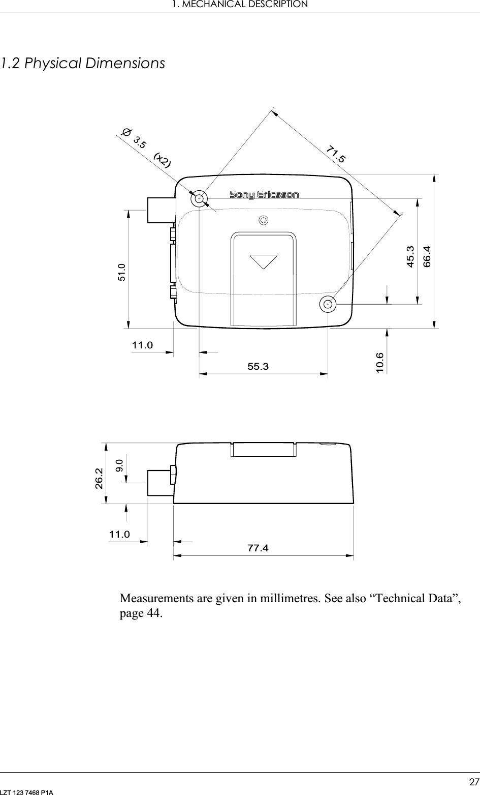
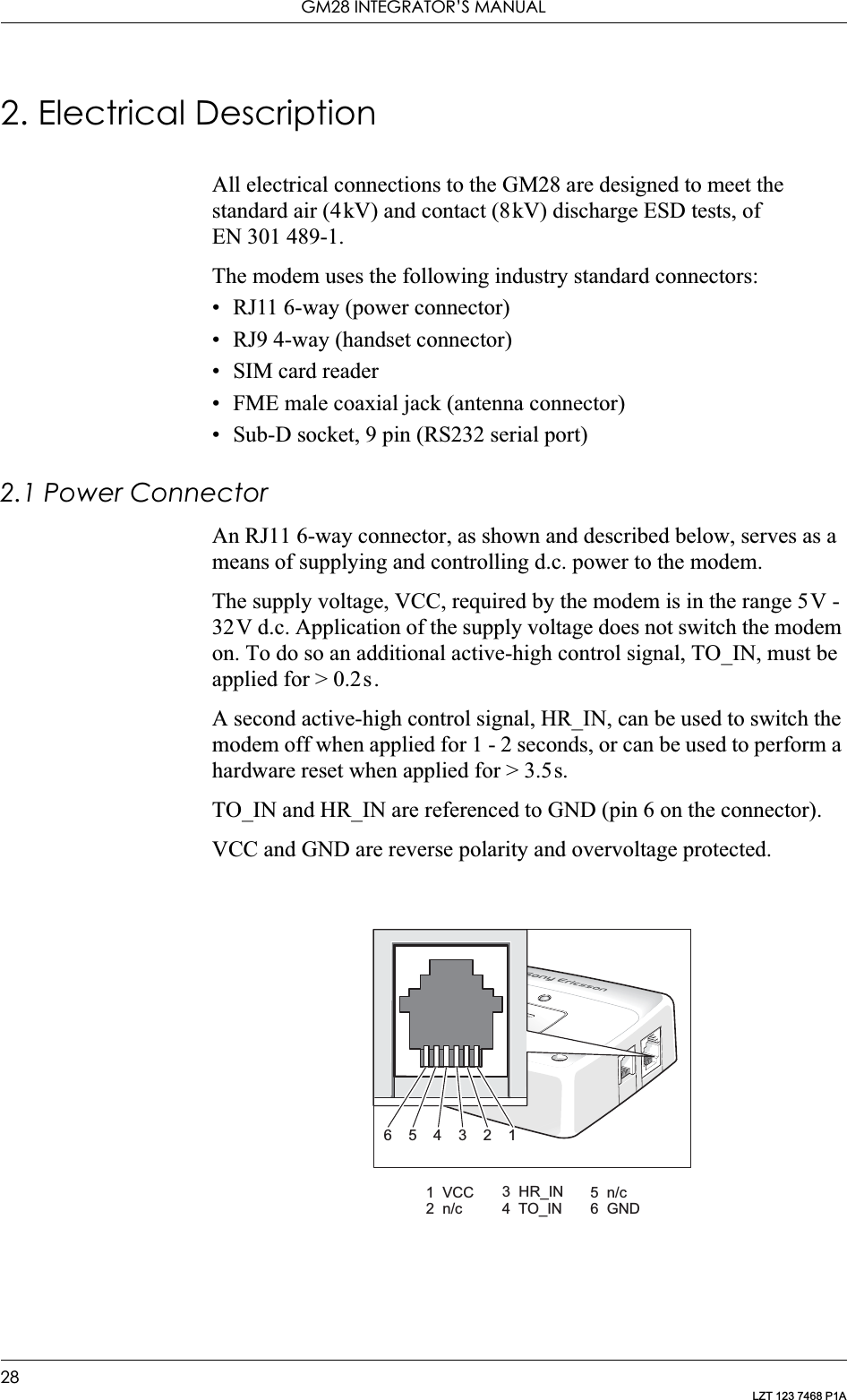
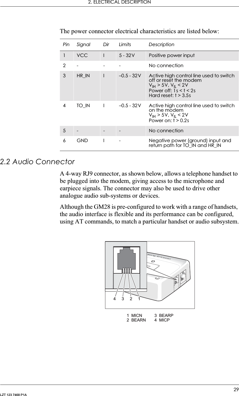
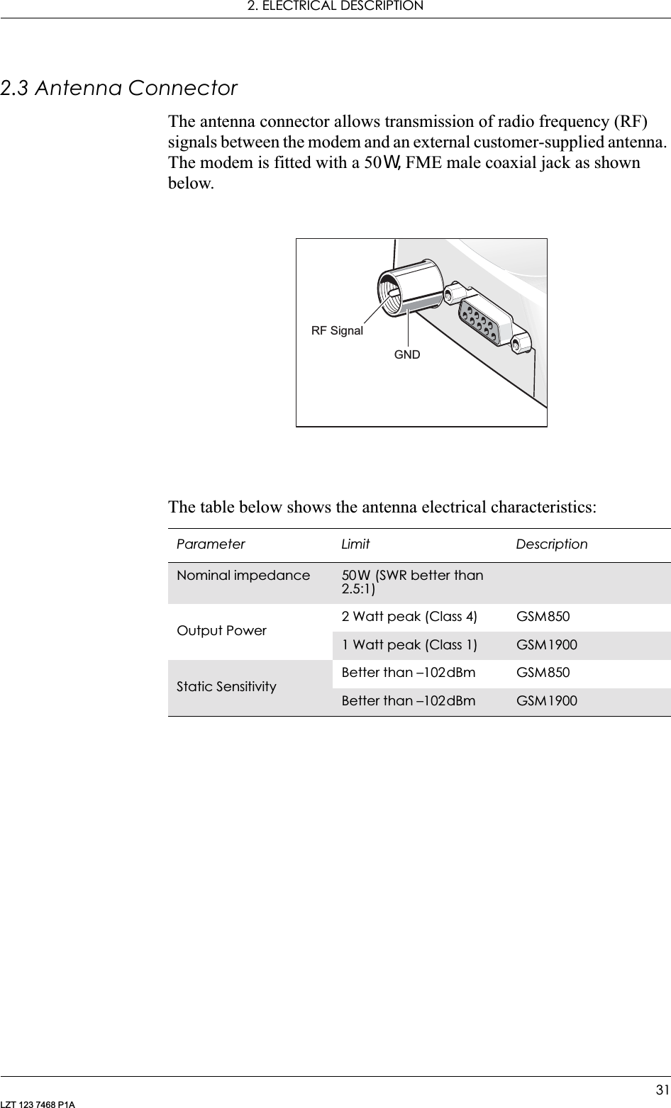
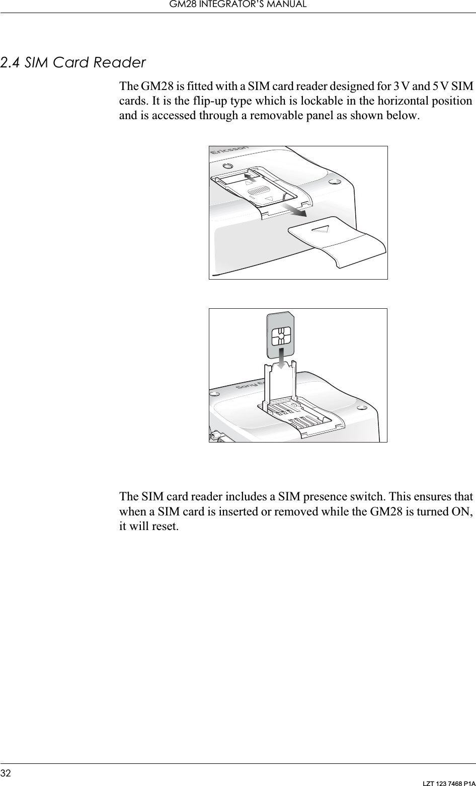
Integrators User Manual


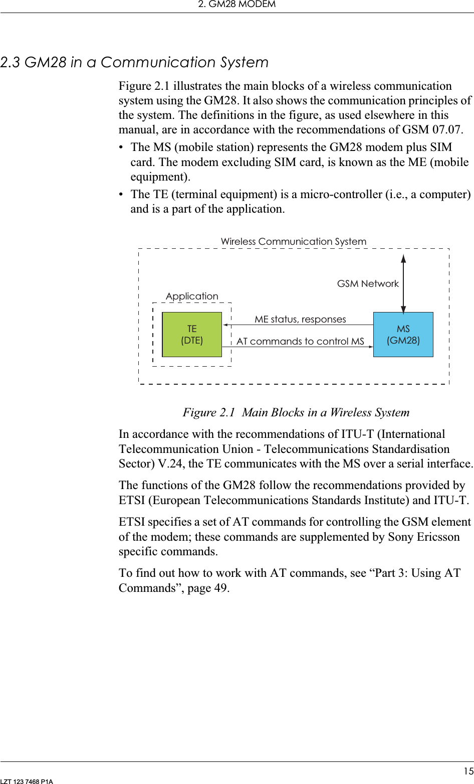
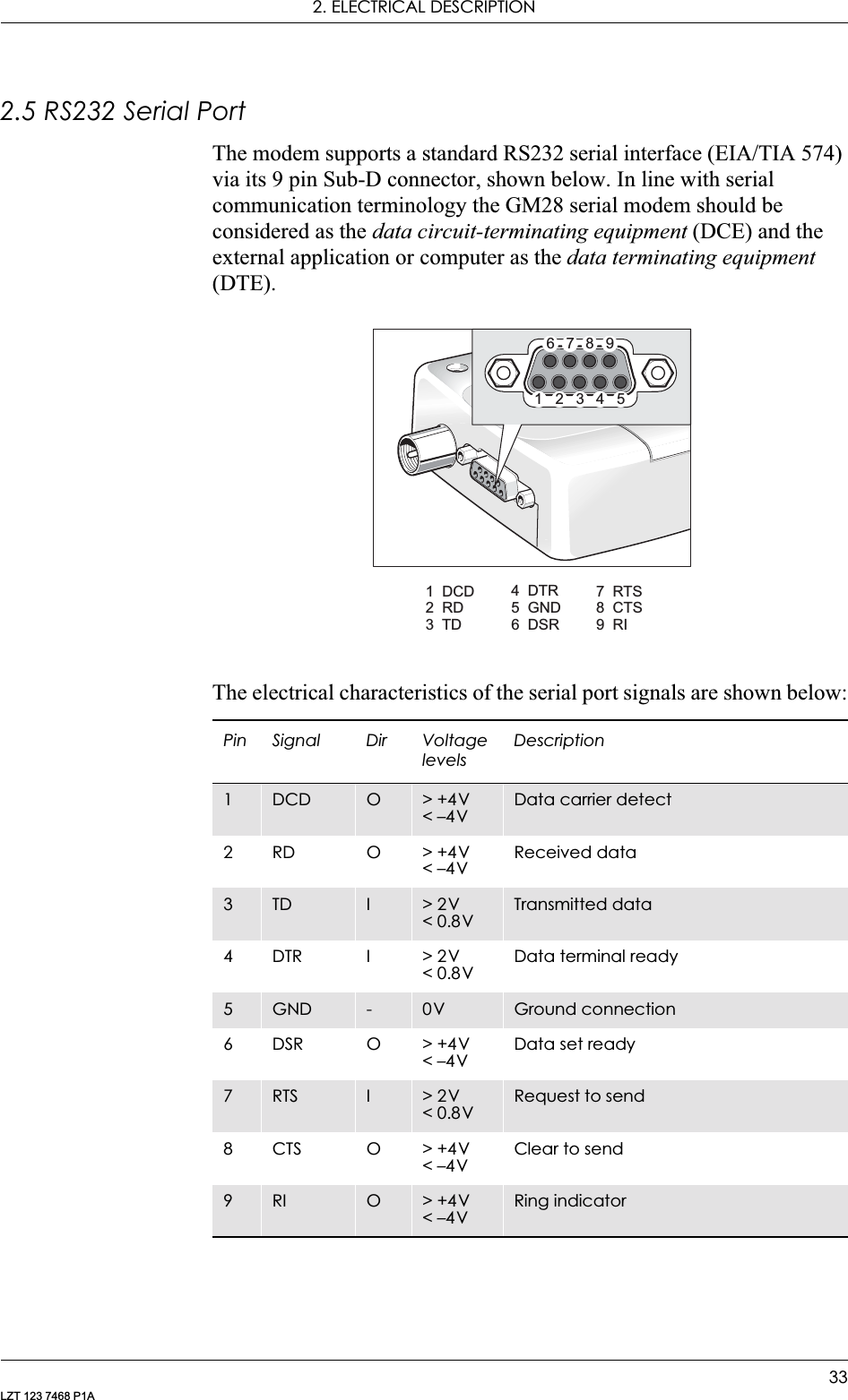
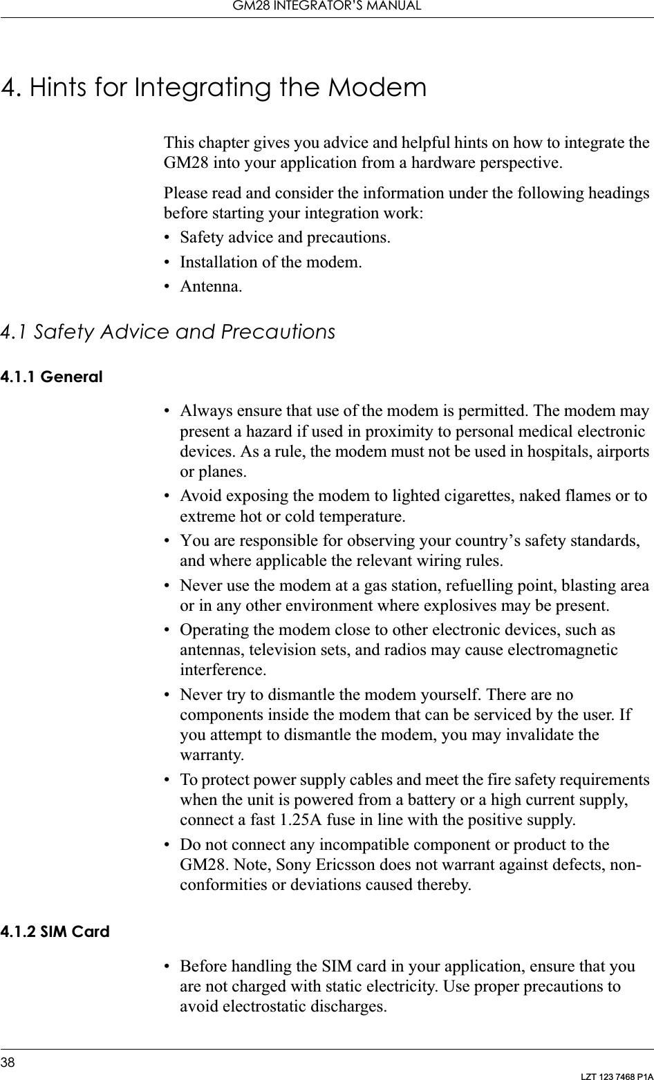
![GM28 INTEGRATOR’S MANUAL30LZT 123 7468 P1AAudio signal descriptions are listed below:MICP and MICN are balanced differential microphone input signals. These inputs are compatible with an electret microphone.BEARP and BEARN are the speaker output signals. These are differential-mode outputs. The electrical characteristics are given in the table below.The following table shows the ear piece impedances that can be connected to BEARP and BEARN.Note! Compliance with AMR may be required by certain network operators.Pin Signal Dir Description1MICN IMicrophone negative input2 BEARN O Earpiece negative output3BEARP OEarpiece positive output4 MICP I Microphone positive inputParameter LimitOutput level (differential) t4.0VppOutput level (dynamic load = 32:)t2.8VppDistortion at 1kHz and maximum output level d5%Offset, BEARP to BEARN ±30mVEar-piece mute-switch attenuation t40dBEar piece model Impedance ToleranceDynamic ear piece [32:+ 800µH] // 100pF ±20%Dynamic ear piece [150:+ 800µH] // 100pF ±20%Piezo ear piece 1k:+ 60nF ±20%](https://usermanual.wiki/Sony/6220502-BV.Integrators-User-Manual/User-Guide-324170-Page-30.png)
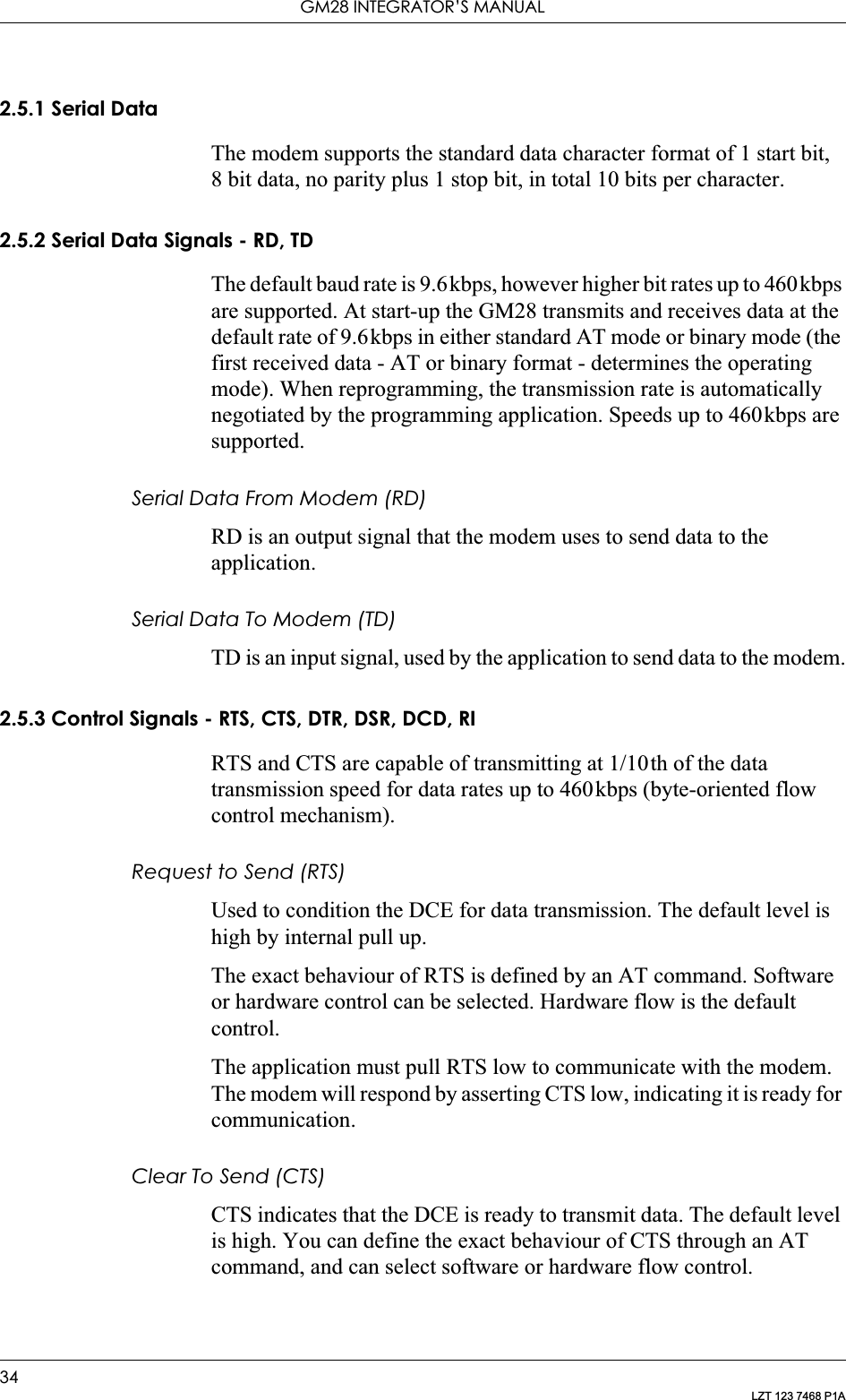
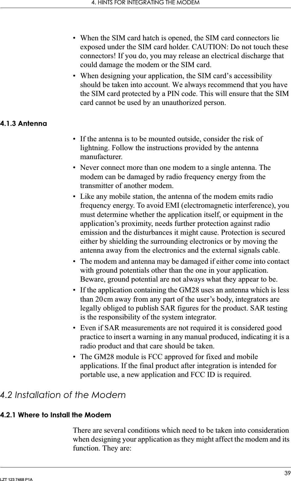
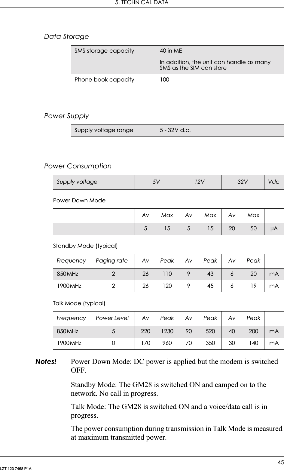
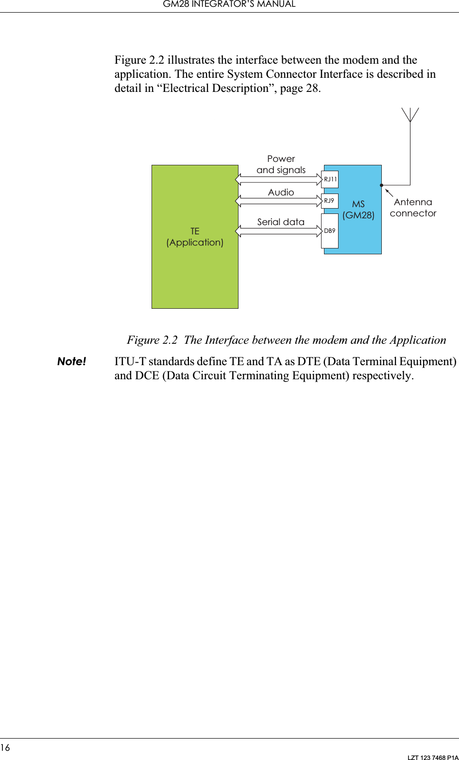
![GM28 INTEGRATOR’S MANUAL46LZT 123 7468 P1AThe power consumption in Standby Mode is measured at the maximum paging rate.Radio SpecificationsAudio SpecificationsSIM Card ReaderFrequency range GM28: GSM 850MHz and 1900MHz (dual band)Maximum RF output power2W (850MHz) and 1W (1900MHz)Antenna impedance 50: Static sensitivity Better than –102dBmE-OTD Currently unsupported in GM28Parameter LimitOutput level (differential) t4.0VppOutput level (dynamic load = 32:)t2.8VppDistortion at 1kHz and maximum output level d5%Offset, BEARP to BEARN ±30mVEar-piece mute-switch attenuation t40dBEar piece model Impedance ToleranceDynamic ear piece [32:+ 800µH] // 100pF ±20%Dynamic ear piece [150:+ 800µH] // 100pF ±20%Piezo ear piece 1k:+ 60nF ±20%Voltage type Support for 3 V and 5 V SIM cards](https://usermanual.wiki/Sony/6220502-BV.Integrators-User-Manual/User-Guide-324170-Page-46.png)
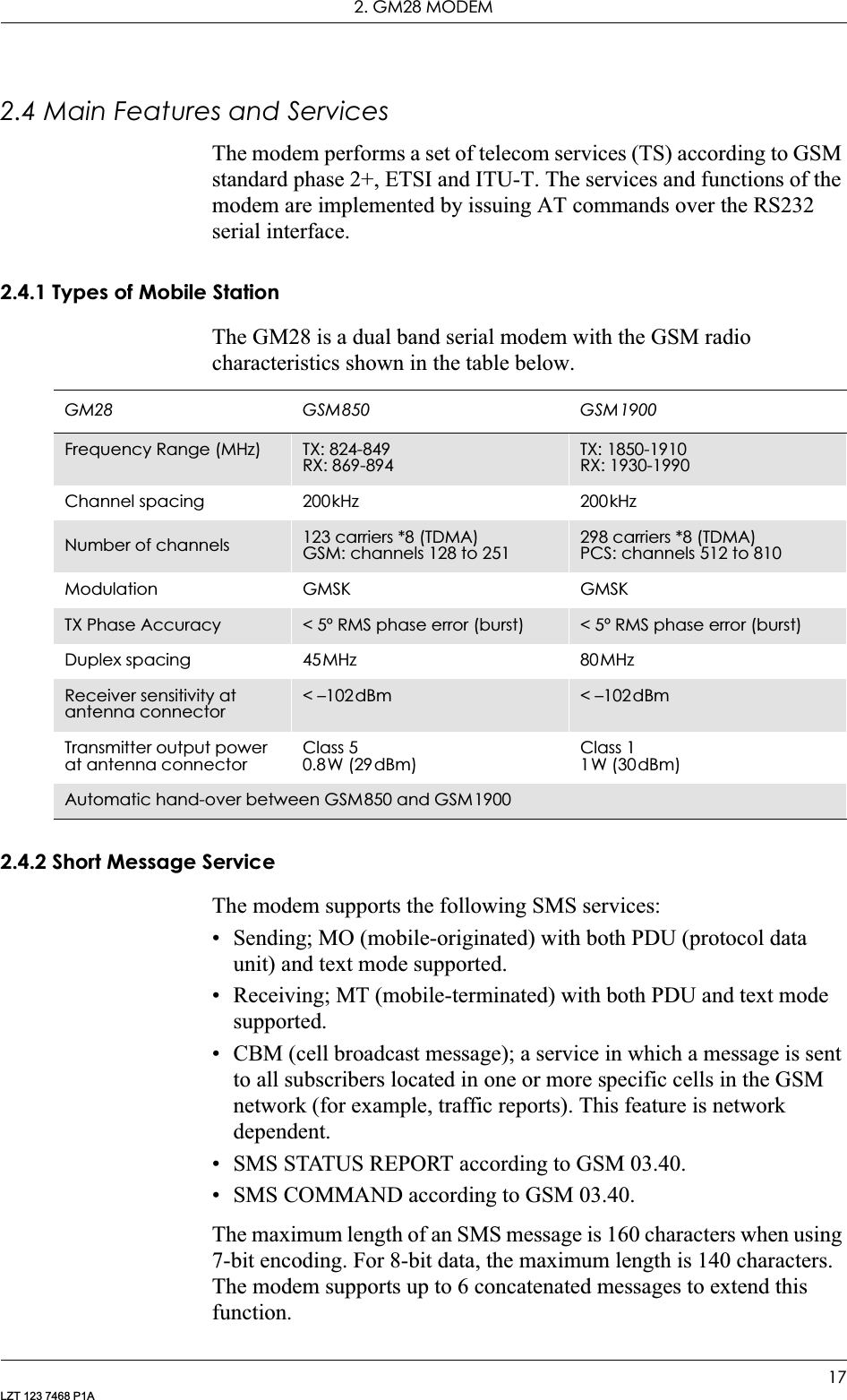
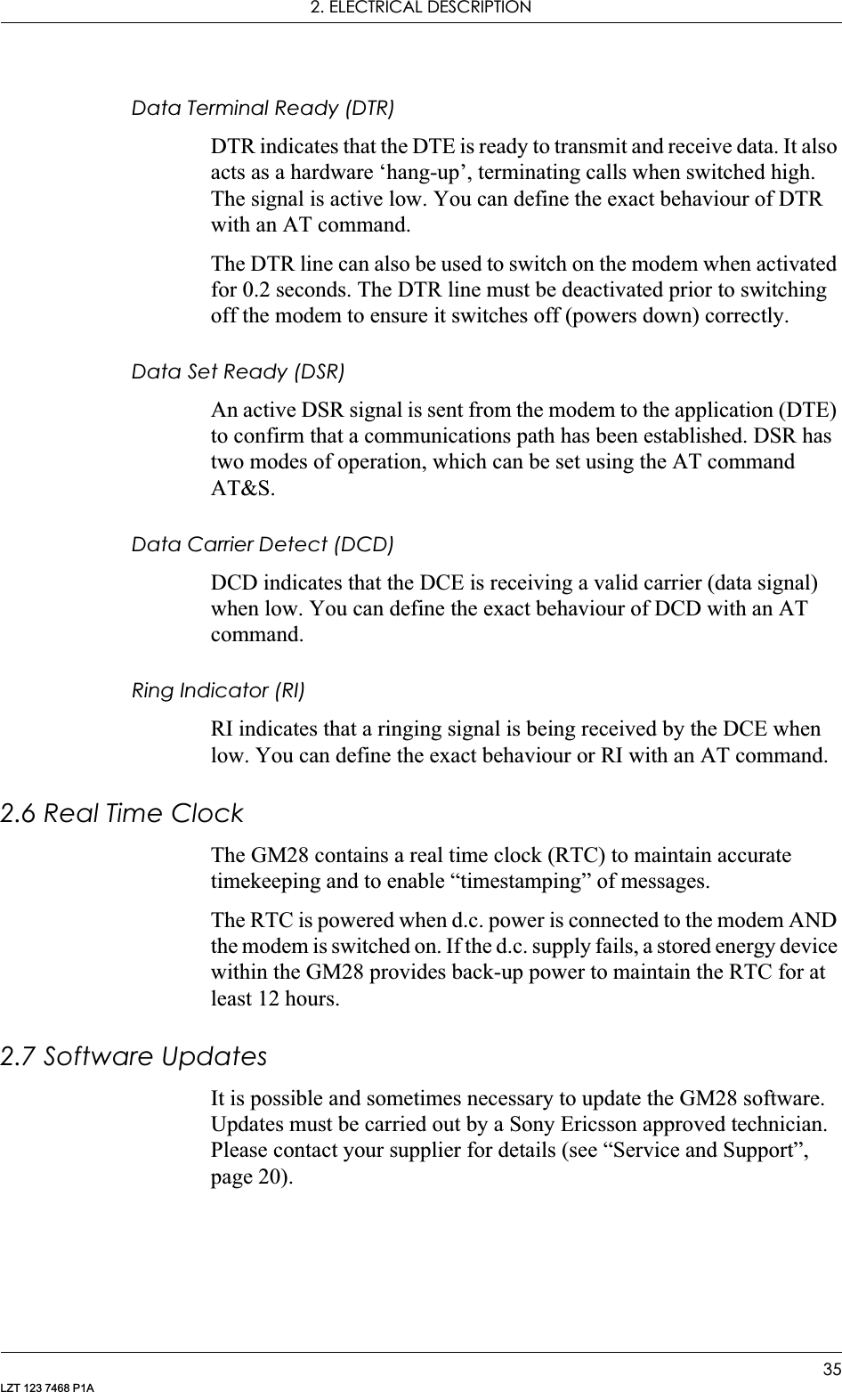
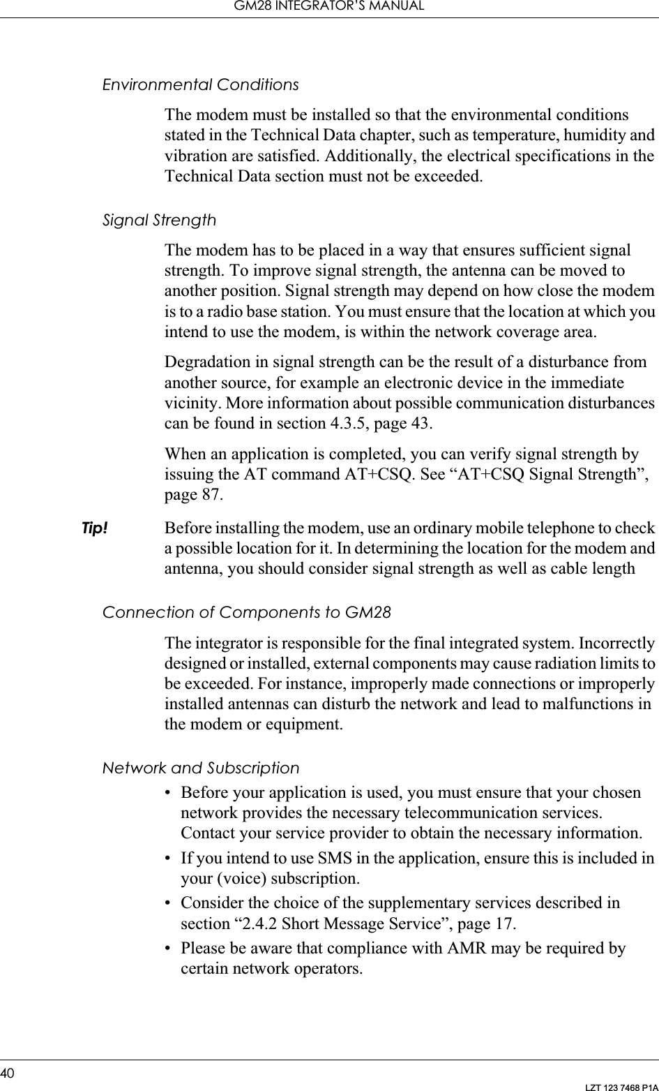
![GM28 INTEGRATOR’S MANUAL52LZT 123 7468 P1A[ ] Square brackets are used to indicate that a certain item is optional. For example, sub-parameters of a command or an optional part of a response. The brackets do not appear in the command line.Value The default values of the supported parameters are indicated by using bold text when presenting the value.• Other characters, including ‘?’, ‘ ’, parenthesis, etc., appear in commands and responses as written.• The final result codes OK, ERROR, +CME ERROR: <err> and CMS ERROR:<err> (see sections 1.2.3, AT Response Syntax and 1.3, Error Codes) are not listed under “Possible Responses” for each AT command. • OK and ERROR are listed if these are the only possible responses.1.2.2 AT Command SyntaxThe AT standard is a line-oriented command language. Each command is made up of the following three elements:• the prefix;• the body;• the termination character.The prefix consists of the letters “AT”, which are derived from the first two letters of the word attention. The body is made up of the command, the parameter, and if applicable the associated values.Commands may be combined in the same command line. Spaces between the individual bodies are ignored.Basic Syntax CommandThe format of basic syntax commands is as follows:AT<command>[=][<parameter>]<OK>Example! ATL=0<CR> (sets the volume of the speaker)Additional commands may follow a command on the same command line without any character being required for separation. For the command D parameters, see the description for the command in question.A version of the basic syntax is:AT<command><parameter>Extended Syntax Command• AT+<command>= [<parameter>]](https://usermanual.wiki/Sony/6220502-BV.Integrators-User-Manual/User-Guide-324170-Page-52.png)
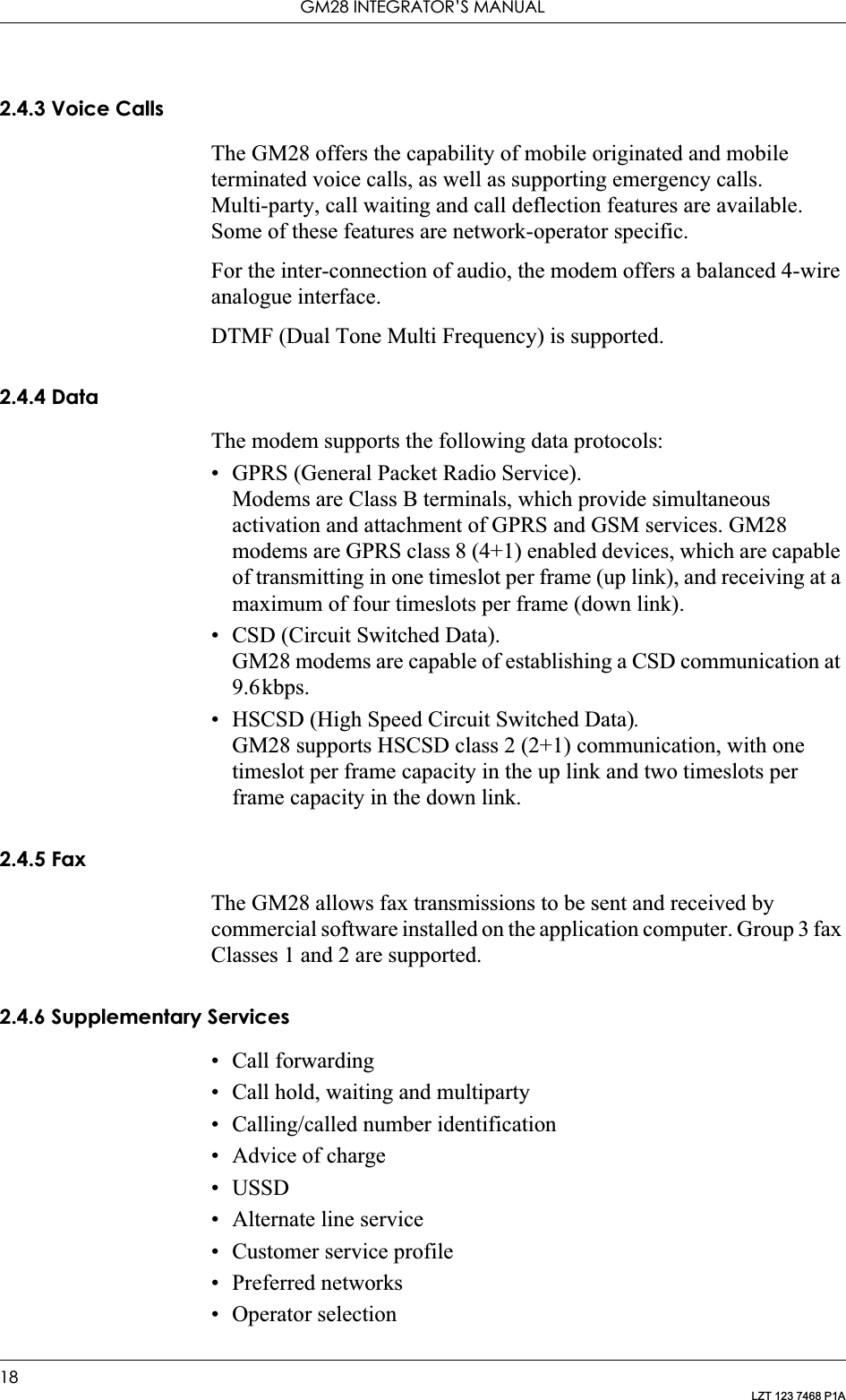
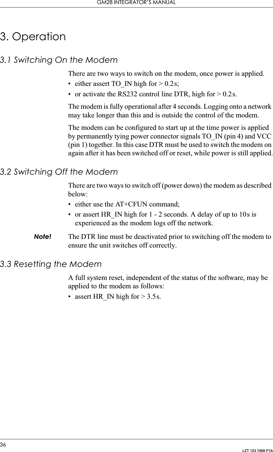
![1. INTRODUCTION TO AT COMMANDS53LZT 123 7468 P1A• AT*<command>=[<parameter>]Example! AT+CFUN=0<CR> (powers down the modem)If several values are included in the command, they are separated by commas. It is also possible to enter commands with no values.Additional commands may follow an extended syntax command on the same command line if a semicolon (; IRA 3B) is inserted after the preceeding extended command as a separator.Read Command SyntaxThe read command is used to check the current values ofparameters. Type ‘?’, after the command line:• AT+<command>?• AT*<command>?• AT<command>?Example! AT+CSCS?<CR> (show current character set)<CR>“IRA”<CR>(information text response)<CR>OK<CR>(final result code response)Test Command SyntaxThe test command is used to test whether the command has beenimplemented or to give information about the type of subparameters itcontains. Type ‘?’, after the command line:• AT+<command>=?• AT*<command>=?Example! AT+CPAS=?<CR> (shows supported values for the response parameters)<CR>CPAS: (0, 3, 4, 129, 130, 131)<CR> (supported values)<CR>OK<CR> (final result code)If the indicated <parameter> is not recognized, the result code ERROR is issued.Note! Possible responses are indicated both as <command>:(list of supported<parameter>) and (in most cases) the actual range of the parameter values.1.2.3 AT Response SyntaxThe default mode response shown below, is in text mode. See the command V for further details.](https://usermanual.wiki/Sony/6220502-BV.Integrators-User-Manual/User-Guide-324170-Page-53.png)
![GM28 INTEGRATOR’S MANUAL60LZT 123 7468 P1A2.3 ATD DialUsed to initiate a phone connection, which may be data or voice (phone number terminated by semicolon). The phone number used to establish the connection will consist of digits and modifiers, or a stored number specification.If the dial string is followed by a semicolon this informs the phone that the number is a voice rather than a data number.If the dial string is omitted, and the semicolon included, the command instructs the ME to do a network detect. If the network is available OK is returned.Abortability:Aborting an ATD command is accomplished by the transmission from the DTE to the DCE of any character. A single character shall be sufficient to abort the command in progress; however, characters Description Command Possible Responses• Originate a call and dial the phone number specified in the command as <dial_string>or•Do a network detectATD<dial_string>[;] •CONNECT• CONNECT <text>•NO CARRIER•ERROR• NO DIAL TONE•BUSY•OKDial the phone number stored in the mobile phone which is located by the index <I>ATD>ME<I>[;] • CONNECT• CONNECT <text>•NO CARRIER•ERROR• NO DIAL TONE•BUSY•OKDial the phone number stored in the SIM card which is located by the index <I>ATD>SM<I>[;] •CONNECT• CONNECT <text>•NO CARRIER•ERROR• NO DIAL TONE•BUSY•OKDial the phone number stored in the Last dialled number list on the SIM card, which is located by the index <I>The most recently dialled number is assumed to have <I>="1"ATD>LD<I>[;] • CONNECT• CONNECT <text>•NO CARRIER•ERROR• NO DIAL TONE•BUSY•OKRedial the last phone number dialled.Ericsson specificATDL[;] ...](https://usermanual.wiki/Sony/6220502-BV.Integrators-User-Manual/User-Guide-324170-Page-60.png)
![GM28 INTEGRATOR’S MANUAL62LZT 123 7468 P1A2.4 ATH Hang upSignals the MS to terminate an active call.2.5 ATO Return to Online Data ModeSwitch to the on-line data mode from the on-line command mode during an active call. Returns ERROR when not in on-line command mode.2.6 ATP Select Pulse DiallingCommand is ignored, and is implemented for compatibility only. It would normally cause the next D command to use pulses when dialling the number.2.7 ATT Select Tone DiallingCommand is ignored, and is implemented for compatibility only. It would normally cause the next D command to use tones when dialling the number.Description Command Possible ResponsesTerminate the call ATH •ERROR•OKDescription Command Possible ResponsesReturn to on-line data modeATO[<value>] •CONNECT• CONNECT <text>•NO CARRIER•ERROR<value> Description0Return to on-line data state from on-line commandDescription Command Possible ResponsesSelect pulse dialling ATP OKShow if the command is supported?ATP=? OKDescription Command Possible ResponsesSelect tone dialling ATT OKShow if the command is supported?ATT=? OK](https://usermanual.wiki/Sony/6220502-BV.Integrators-User-Manual/User-Guide-324170-Page-62.png)
![2. CALL CONTROL63LZT 123 7468 P1A2.8 ATX Call Progress Monitoring ControlDefines if the dial-tone detection and busy-tone detection are to be used during a call set-up.Note! If there is no network available the <n> parameter will decide if “NO DIALTONE” or “NO CARRIER” will be returned. If the call recipient is busy, the <n> parameter will decide if “BUSY” or “NO CARRIER” will be returned.2.9 AT+CHUP Hang up CallCauses the TA to hang-up the current call of the ME.If no call is present, but an incoming call is notified, then the incoming call shall be rejected.Description Command Possible ResponsesSet call progress monitoring controlATX=[<n>] or ATX[<n>] •OK•ERRORRead the current settingATX? X: <n>Show if the command is supported?ATX=? X: (list of supported <n>s)<n> Description0Body and dial tone detection off. No line speed reported on connection1 Body and dial tone detection off. Report line speed on connection2Busy detection on and dial tone detection off. Report line speed on connection3 Busy detect off and dial tone on. Report line speed on connection4Busy detect and dial tone detection on. Report line speed on connection. Default valueDescription Command Possible ResponsesRequest hang-up AT+CHUP •OK•ERRORShow if the commands is supportedAT+CHUP=? • OK•ERROR](https://usermanual.wiki/Sony/6220502-BV.Integrators-User-Manual/User-Guide-324170-Page-63.png)
![GM28 INTEGRATOR’S MANUAL64LZT 123 7468 P1A2.10 AT+CMOD Call ModeSelects the call mode of further dialing commands (D) or for next answering command (A). Mode can be either single or alternating. In this ETS, terms “alternating mode” and “alternating call” refer to all GSM bearer and teleservices that incorporate more than one basic service (voice, data, fax) within one call.When single mode is selected the call originating and hang-up procedures are similar to procedures specified in ITU-T Recommendations V.25ter, T.31 and T.32. In GSM there can be voice followed by data (refer to GSM 02.02), alternating voice/data (refer to GSM 02.02) and alternating voice/fax calls (refer to GSM 02.03).Test command returns values supported by the TA as a compound value.Note! +CMOD is set to zero after a successfully completed alternating mode call. It is set to zero also after a failed answering. The power-up, factory (&F) and user resets (Z), also set the value to zero. This reduces the possibility that alternating mode calls are originated or answered accidentally.Description Command Possible ResponsesRequest Call Mode AT+CMOD=[<mode>] •OK•ERRORShows the current settingAT+CMOD? • +CMOD: <mode>•OK•ERRORShow if the command is supportedAT+CMOD=? • +CMOD: (list of supported <mode>s)•OK•ERROR<mode> Description0Single mode. Default value.In order to avoid accidental originating or answering of alternating calls is <mode> set to single mode in following cases:- after a successfully completed alternating mode call;- after a unsuccessful answering;- after successfully execution of the commands &F and Z](https://usermanual.wiki/Sony/6220502-BV.Integrators-User-Manual/User-Guide-324170-Page-64.png)
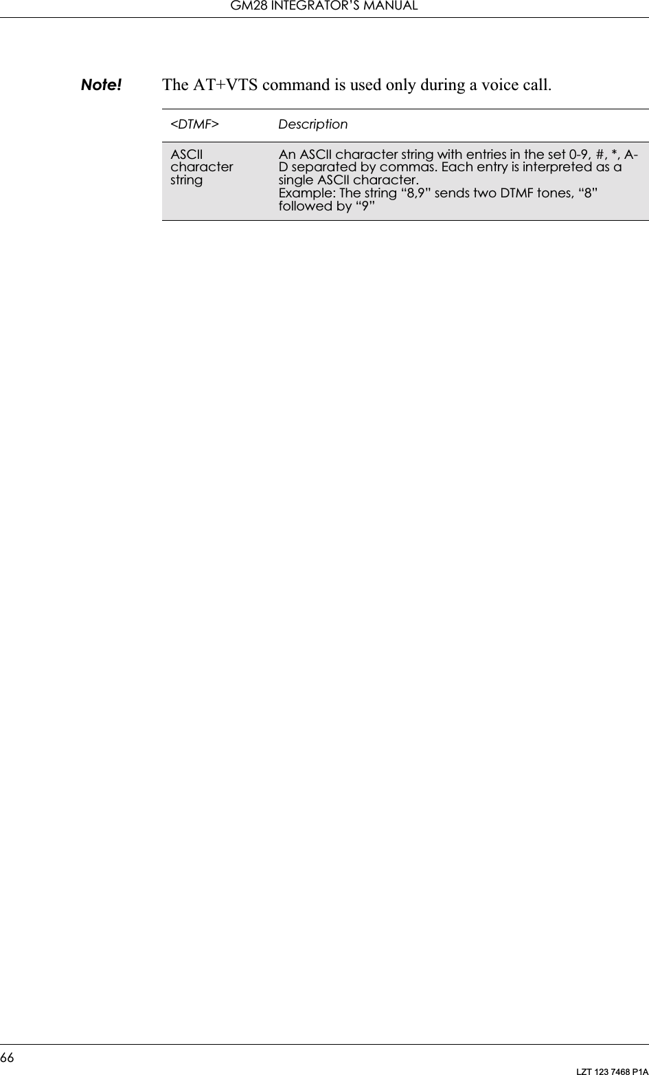
![2. CALL CONTROL65LZT 123 7468 P1A2.11 AT+CVHU Voice Hang-UpSelects whether ATH or “drop DTR” causes a voice connection to be disconnected or not. Voice connection also includes alternating mode calls that are currently in voice mode.Note! When <mode>=2, this command must be viewed in conjunction with the V.25ter command &D, or &D will be ignored.2.12 AT+VTS DTMF and Tone GenerationThis command allows the transmission of DTMF tones. These tones may be used, for example, when announcing the start of a recording period. The command is write only. In this profile of commands, the command does not operate in data or fax modes of operation (+FCLASS=0,1,2-7).Note! The ATD-command is used only for dialing. It is not possible to generate arbitrary DTMF tones using the ATD command.Description Command Possible ResponsesSet Command +CVHU=[<mode>] • +CME ERROR: <err>•OKRead command +CVHU? • +CVHU: <mode>• +CME ERROR: <err>Test if the command is supported+CVHU=? +CVHU: (list of supported <mode>s)<mode> Description0“Drop DTR” ignored but OK response given. ATH disconnects1 “Drop DTR” and ATH ignored but OK response given2“Drop DTR” behavior according to &D setting. ATH disconnects. Default valueDescription Command Possible ResponsesRequest transmission of DTMF tone(s)AT+VTS=<DTMF> OKERRORShow if the command is supportedAT+VTS=? OKERROR](https://usermanual.wiki/Sony/6220502-BV.Integrators-User-Manual/User-Guide-324170-Page-65.png)
![67LZT 123 7468 P1A3. Control and Status3.1 ATQ Result Code SuppressionDetermines whether or not the DCE transmits result codes to the DTE. When result codes are being suppressed, no portion of any intermediate, final, or unsolicited result code - header, result text, line terminator, or trailer - is transmitted.3.2 ATS0 Automatic Answer ControlDefines the automatic answering feature of the modem. A non-zero value specifies the number of rings before the call is answered.Note! Call is always answered in the current fax class, regardless of whether the incoming call is voice, data, or fax.Description Command Possible ResponsesSet Result Code SuppressionATQ[=]<value> •OK•ERRORRead the current settingATQ? Q: <value>Show if the command is supportedATQ=? Q: (list of supported <value>s)<value> Description0DCE transmits result codes. Default value1 Result codes are suppressed and not transmittedDescription Command Possible ResponsesAutomatic answer controlATS0=[<rcnt>] •OK•ERRORRead the current settingATS0? <rcnt>Show if the command is supportedATS0=? S0: (list of supported <rcnt>s)<rcnt> Description0Disable automatic answer. Default value1-7 Answer after the specified number of rings](https://usermanual.wiki/Sony/6220502-BV.Integrators-User-Manual/User-Guide-324170-Page-67.png)
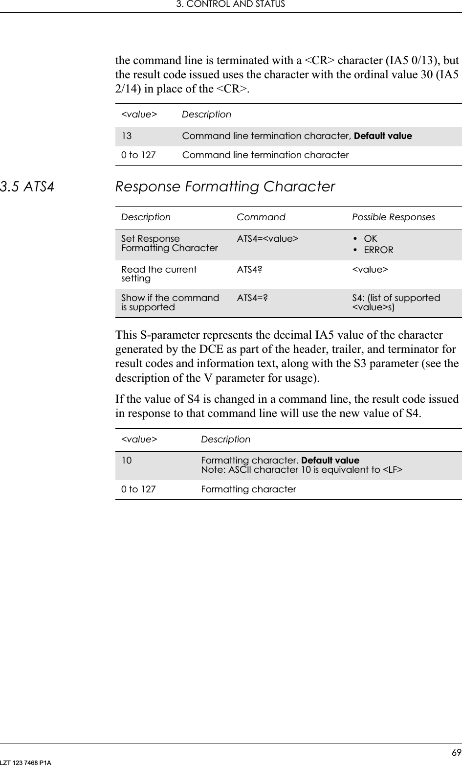
![GM28 INTEGRATOR’S MANUAL68LZT 123 7468 P1A3.3 ATS2 Escape Sequence CharacterDefines the character to be used as the escape sequence character when switching from on-line data mode to on-line command mode. The response to the command is modified to reflect the change.Note! If the <esc> parameter is set to a value in the range of 128-255, the escape sequence detection is disabled.3.4 ATS3 Command Line Termination CharacterThis S-parameter represents the decimal IA5 value of the character recognised by the DCE from the DTE to terminate an incoming command line. It is also generated by the DCE as part of the header, trailer, and terminator for result codes and information text, along with the S4 parameter.The previous value of S3 is used to determine the command line termination character for entry of the command line containing the S3 setting command. However, the result code issued uses the value of S3 as set during the processing of the command line. For example, if S3 was previously set to 13 and the command line “ATS3=30” is issued, Description Command Possible ResponsesSet escape sequence characterATS2=[<esc>] •OK•ERRORRead the current settingATS2 <esc>Show if the command is supportedATS2=? S2: (list of supported <esc>s)<esc> Description43 Escape sequence character. Default value0 to 255 Escape sequence characterDescription Command Possible ResponsesSet Command Line Termination CharacterATS3=<value> •OK•ERRORRead the current settingATS3? <value>Show if the command is supportedATS3=? S3: (list of supported <value>s)](https://usermanual.wiki/Sony/6220502-BV.Integrators-User-Manual/User-Guide-324170-Page-68.png)
![GM28 INTEGRATOR’S MANUAL70LZT 123 7468 P1A3.6 ATS5 Command Line Editing Character (BACKSPACE)This S-parameter represents the decimal IA5 value of the character recognised by the DCE as a request to delete from the command line the immediately preceding character.3.7 ATS6 Blind Dial Delay ControlIncluded for compatibility. No functionalityDescription Command Possible ResponsesRequest Command Line Editing CharacterATS5=<value> •OK•ERRORShows the current settingATS5? <value>Show if the command is supportedATS5=? S5: (list of supported <value>s)<value> Description8Line editing character. Default value0 to 127 Line editing characterDescription Command Possible ResponsesBlind dial delay control ATS6=[<dly>] OKRead the current settingATS6? <dly>Show if the command is supportedATS6=? S6: (list of supported <dly>s)<dly> Description2Wait two seconds before blind dialling. Default value2-255 Number of seconds to wait before blind dialling](https://usermanual.wiki/Sony/6220502-BV.Integrators-User-Manual/User-Guide-324170-Page-70.png)
![3. CONTROL AND STATUS71LZT 123 7468 P1A3.8 ATS7 Connection Completion TimeoutDefines the maximum time allowed between completion of dialling and the connection being established. If this time is exceeded then the connection is aborted.3.9 ATS8 Comma Dial Modifier Delay ControlIncluded for compatibility. No functionalityDescription Command Possible ResponsesSet connection completion timeoutATS7=[<tmo>] •OK•ERRORRead the current settingATS7? <tmo>Show if the command is supportedATS7=? S7: (list of supported <tmo>s)<tmo> Description50 Timeout value in seconds. Default value1-255 Timeout value in secondsDescription Command Possible ResponsesSet Comma Dial Modifier Delay ControlATS8=[<dly>] •OK•ERRORRead the current setting.ATS8? <dly>Show if the command is supported.ATS8=? S8: (list of supported <dly>s)<dly> Description2The value of the dial modifier delay in seconds. Default value1-255 The value of the dial modifier delay in seconds](https://usermanual.wiki/Sony/6220502-BV.Integrators-User-Manual/User-Guide-324170-Page-71.png)
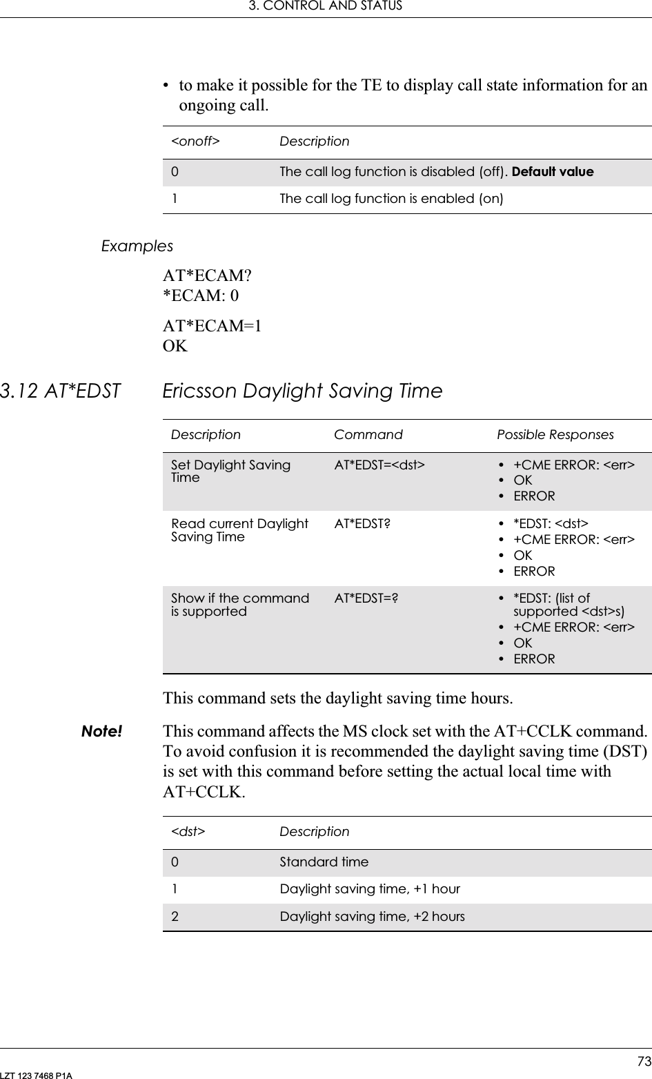
![GM28 INTEGRATOR’S MANUAL72LZT 123 7468 P1A3.10 ATS10 Automatic Disconnect Delay ControlIncluded for compatibility. No functionality3.11 AT*ECAM Ericsson Call MonitoringThis command activates or deactivates the call monitoring function in the ME. When this log function is activated in the ME, the ME informs about call events, such as incoming call, connected, hang up etc.It is preferable that the current status shall always be sent with result code *ECAV when activating the log function. The purpose of this is two fold:• to gather relevant information for the call log in a TE;Description Command Possible ResponsesSet Automatic Disconnect Delay ControlATS10=[<val>] •OK•ERRORRead the current settingATS10? <val>Show if the command is supportedATS10=? S10: (list of supported <val>s)<val> Description2Remains connected for two tenths of a second. Default value1-254 Number of tenths of a second of delayDescription Command Possible ResponsesSet Call Monitoring on or offAT*ECAM=<onoff> •OK• +CME ERROR: <err>•OK•ERRORRead the current status for Call MonitoringAT*ECAM? • *ECAM: <onoff>• +CME ERROR: <err>•OK•ERRORTest if the command is supportedAT*ECAM=? • *ECAM: list of supported <onoff>s• +CME ERROR: <err>•OK•ERROR](https://usermanual.wiki/Sony/6220502-BV.Integrators-User-Manual/User-Guide-324170-Page-72.png)
![3. CONTROL AND STATUS77LZT 123 7468 P1A3.18 AT+CIND Indicator ControlUsed to set the values of ME indicators. <ind> value 0 means that the indicator is off (or in state which can be identified as “off” state), 1 means that indicator is on (or in a state which is more substantial than “off” state), 2 is more substantial than 1, and so on. If the indicator is a simple on/off style element, it has values 0 and 1. The number of elements is ME specific. If the ME does not allow setting of indicators or it is not currently reachable, +CME ERROR: <err> is returned. If a certain indicator is not writable, it cannot be set. If the parameter is an empty field, the indicator will keep the previous value.Test command returns pairs, where string value <descr> is a maximum 16 character description of the indicator and compound value is the allowed values for the indicator. If ME is not currently reachable, +CME ERROR: <err> is returned (refer to GSM 07.07).Description Command Possible ResponsesSet Indicator ControlAT+CIND=[<ind> [,<ind>[,…]]]• +CME ERROR: <err>•OK•ERRORRead the current settingAT+CIND? • +CIND: <ind>,<ind>,…• +CME ERROR: <err>•OK•ERRORTest if the command is supportedAT+CIND=? • +CIND: (<descr>,(list of supported <ind>s)), (<descr>,(list of supported <ind>s)),…• +CME ERROR: <err>•OK•ERROR<ind> DescriptionInteger type Value shall be in range of corresponding <descr> <descr> Description“signal” Signal quality (0-5)“service” Service availability (0-1)“sounder” Sounder activity (0-1)“message” Message received (0-1)“call” Call in progress (0-1)“roam” Roaming indicator (0-1)“sms full” A short message memory storage in the MT has become full (1), or memory locations are available (0); i.e. the range is (0-1)](https://usermanual.wiki/Sony/6220502-BV.Integrators-User-Manual/User-Guide-324170-Page-77.png)
![GM28 INTEGRATOR’S MANUAL78LZT 123 7468 P1A3.19 AT+CLAC List all available AT CommandsCauses the ME to return one or more lines of AT commands. This command has the same functionality as AT*.Note! This command only returns the AT commands that are available to the user.3.20 AT+CMEE Mobile Equipment ErrorDisables or enables the use of result code +CME ERROR: <err> as an indication of an error relating to the functionality of the ME. When enabled, ME related errors cause +CME ERROR: <err> final result code instead of the regular ERROR final result code. ERROR is returned normally when error is related to syntax, invalid parameters, or TA functionality. For more information, refer to “+CME ERROR (Mobile Equipment Error Code)”, page 55.Command Possible Responses+CLAC <AT Command1> [<CR> <LF> <AT Command2>[…]]+CME ERROR: <err>+CLAC=? +CME ERROR: <err>Description Command Possible ResponsesRequest GSM Mobile Equipment Error ControlAT+CMEE=[<n>] •OK•ERRORRead the command AT+CMEE? • +CMEE: <n>•OK•ERRORShow if the command is supportedAT+CMEE=? • +CMEE: (list of supported <n>s)•OK•ERROR<n> Description0Disable +CME ERROR: <err> result code and use ERROR instead. Default value1 Enable +CME ERROR: <err> result code and use numeric <err> values (see page 55)2Enable +CME ERROR: <err> result code and use verbose <err> values (see page 55)](https://usermanual.wiki/Sony/6220502-BV.Integrators-User-Manual/User-Guide-324170-Page-78.png)
![3. CONTROL AND STATUS79LZT 123 7468 P1A3.21 AT+CMER Mobile Equipment Event ReportingEnables or disables the sending of unsolicited result codes from ME to TE in the case of key pressings, display changes, and indicator state changes. <mode> controls the processing of unsolicited result codes specified within this command. <bfr> controls the effect on buffered codes when <mode> 1, 2 or 3 is entered. If the ME does not support setting, +CME ERROR: <err> is returned.Description Command Possible ResponsesSet phone activity statusAT+CMER=[<mode> [,<ind>[,<bfr>]]]• +CME ERROR: <err>•OK•ERRORRead the current settingAT+CMER? • +CMER: <mode>,<ind>,<bfr>•OK•ERRORTest if the command is supportedAT+CMER=? • +CMER: (list of supported <mode>s), (list of supported <ind>s), (list of supported <bfr>s)•OK•ERROR<mode> Description0Buffer unsolicited result codes in the TA; if TA result code buffer is full, codes can be buffered in some other place or the oldest ones can be discarded3 Forward unsolicited result codes directly to the TE; TA-TE link specific inband technique used to embed result codes and data when TA is in on-line data mode<ind> Description0No indicator event reporting1 Indicator event reporting using result code +CIEV: <ind>,<value>. <ind> indicates the indicator order number (as specified for +CIND) and <value> is the new value of indicator. Only those indicator events, which are not caused by +CIND shall be indicated by the TA to the TE<bfr> Description0TA buffer of unsolicited result codes defined within this command is cleared when <mode> 1...3 is entered](https://usermanual.wiki/Sony/6220502-BV.Integrators-User-Manual/User-Guide-324170-Page-79.png)
![GM28 INTEGRATOR’S MANUAL80LZT 123 7468 P1A3.22 AT+CPAS Phone Activity StatusReturns the activity status <pas> of the ME. It can be used to interrogate the ME before requesting action from the phone.When the command is executed without the <mode> argument, the command returns <pas>-values from 0 to 128 (for supported values se table 1 below). When, on the other hand, the command is executed with the <mode> argument set to 1, the command may return Ericsson specific <pas> values from 129 to 255 (for supported values see the table below).Test command returns values supported by the ME as a compound value: refer to GSM 07.07.Description Command Possible ResponsesExecute Phone Activity StatusAT+CPAS[=<mode>] •+CPAS: <pas>•+CME ERROR <err>•OK•ERRORTest if the command is supportedAT+CPAS=? • +CPAS:(list of supported <pas>s)•+CME ERROR <err>•OK•ERROR<pas> Description0Ready (ME allows commands from TA/TE)3 Ringing (ME is ready for commands from TA/TE, but the ringer is active)4Call in progress (ME is ready for commands from TA/TE, but a call is in progress)129 In idle state, (operator name/clock/date). This state is a sub-state to ‘ready’ (0) and has the following definition:In Idle state, that is, operator, clock and date (is set) shown on the displayNo conversation or data call in progressNo sub-menus shown on the display4 Only digits, clear, *, NO and # allowed in this mode, not changing mode130 Mobile oriented call in progress. This is a sub-state to ‘call in progress’131 Mobile terminated call in progress. This is a sub-state to ‘call in progress’<mode> Description1Allows the CPAS to return Ericsson specific <pas> values, such as 129, 130 and 131](https://usermanual.wiki/Sony/6220502-BV.Integrators-User-Manual/User-Guide-324170-Page-80.png)
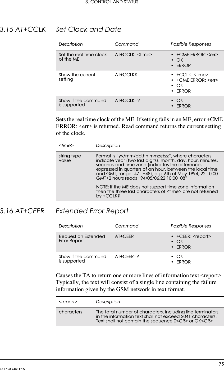
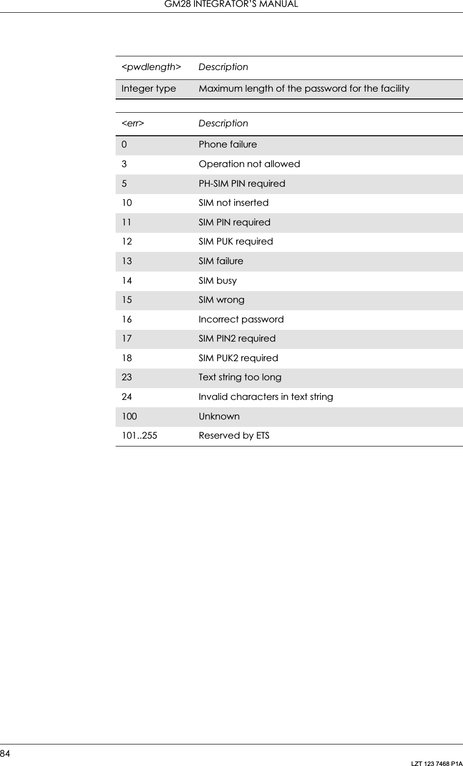
![3. CONTROL AND STATUS81LZT 123 7468 P1A3.23 AT+CPIN PIN ControlSends the password to the ME, which is necessary to make the ME operational (SIM PIN, SIM PUK or PH-SIM). If the PIN is to be entered twice, the TA autonomously repeats the PIN. If no PIN request is pending, no action is taken towards the ME and an error message (+CME ERROR <err>) is returned to the TE.If the PIN required is PUK, the second pin is required. This second PIN, <newpin>, is used to replace the old PIN in the SIM.Note! Commands which interact with the ME that are accepted when the ME has a pending request for SIM PIN, SIM PUK or PH-SIM are: +CGMI, +CGMM, +CGMR, +CGSN, +CFUN, +CMEE +CPIN, L and M.Description Command Possible ResponsesRequest PIN Control AT+CPIN=<pin>[,<newpin>]• +CME ERROR: <err>•OK•ERRORShow the current settingAT+CPIN? • +CPIN: <code>• +CME ERROR: <err>•OK•ERRORShow if the command is supportedAT+CPIN=? • +CME ERROR: <err>•+CPIN: (supported <code>s)•OK•ERROR<pin>,<newpin> Descriptionstring The range for the SIM PIN and the PH- SIM PIN is 4 - 8 digits. The SIM PUK consists of 8 digits<code> DescriptionREADY ME is not pending for any passwordSIM PIN ME is waiting SIM PIN to be givenSIM PUK ME is waiting SIM PUK to be given](https://usermanual.wiki/Sony/6220502-BV.Integrators-User-Manual/User-Guide-324170-Page-81.png)
![3. CONTROL AND STATUS85LZT 123 7468 P1A3.25 AT+CR Service Reporting ControlEnables or disables display of intermediate bearer capability reports during the handshake phase.Intermediate Result Codes:+CR: <serv>3.26 AT+CRC Cellular Result CodeCommand controls whether or not;• the extended format of incoming call indication;• or GPRS network request for PDP context activation;• or notification for VBS/VGCS calls is used.When enabled, an incoming call is indicated to the TE with unsolicited result code +CRING: <type> instead of the normal RING.Description Command Possible ResponsesSet Service Reporting ControlAT+CR=<mode> •OK•ERRORRead current setting AT+CR? • +CR: <mode>•OK•ERRORTest if the command is supportedAT+CR=? • +CR: (list of supported <mode>s)•OK•ERROR<mode> Description0Disable reporting. Default value1 Enable reportingDescription Command Possible ResponsesSet Cellular Result Code optionAT+CRC=[<mode>] •OK•ERRORShow the current settingAT+CRC? • +CRC: <mode>•OK•ERRORShow if the command is supportedAT+CRC=? • +CRC: (list of supported <mode>s)•OK•ERROR](https://usermanual.wiki/Sony/6220502-BV.Integrators-User-Manual/User-Guide-324170-Page-85.png)
![GM28 INTEGRATOR’S MANUAL86LZT 123 7468 P1ATest command returns values supported by the TA as a compound value.Unsolicited Result Codes:+CRING: <type>3.27 AT+CSAS Save SettingsSaves active message service settings to a non-volatile memory. A TA can contain several settings profiles. Settings specified in commands Service Centre Address +CSCA, Set Message Parameters +CSMP and Select Cell Broadcast Message Types +CSCB (if implemented) are saved. Certain settings may not be supported by the storage (e.g. SIM SMS parameters) and therefore can not be saved.Test command shall display the supported profile numbers for reading and writing of settings.<mode> Description0Disables extended format1 Enables extended formatDescription Command Possible ResponsesSave Settings AT+CSAS[=<profile>] • +CMS ERROR: <err>•OK•ERRORGet available profilesAT+CSAS=? • +CSAS: (list of supported <profile>s)• +CMS ERROR: <err>•OK•ERROR<profile> Description0..255 Manufacturer specific profile number where settings are to be stored. Default value is 0](https://usermanual.wiki/Sony/6220502-BV.Integrators-User-Manual/User-Guide-324170-Page-86.png)
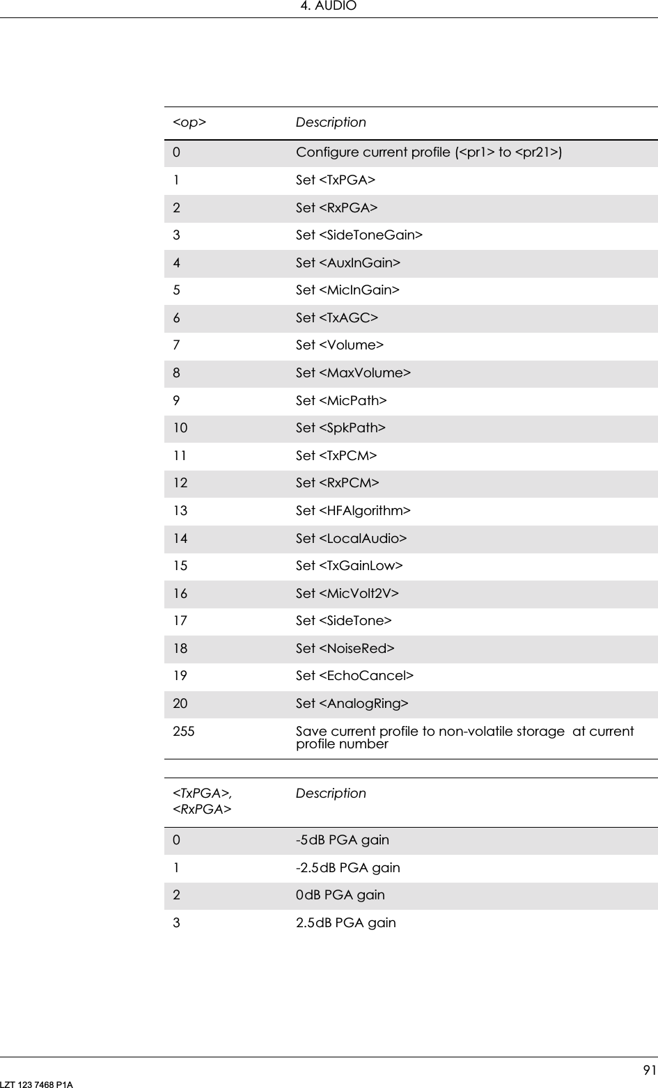
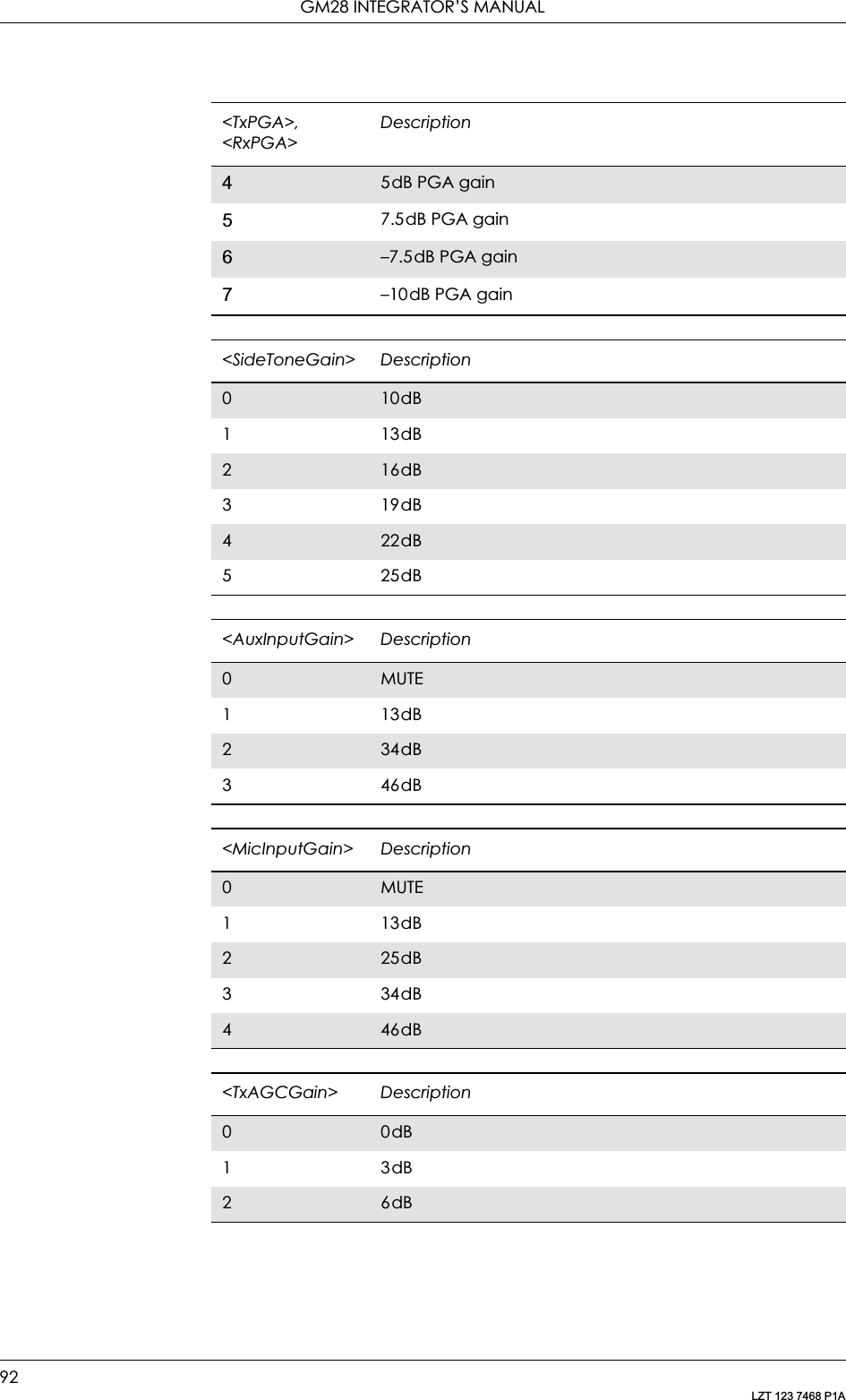
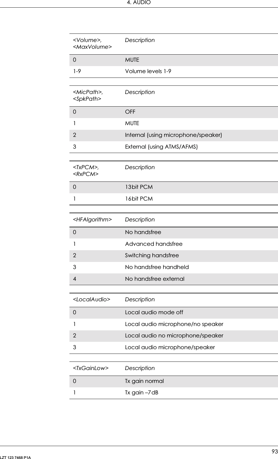
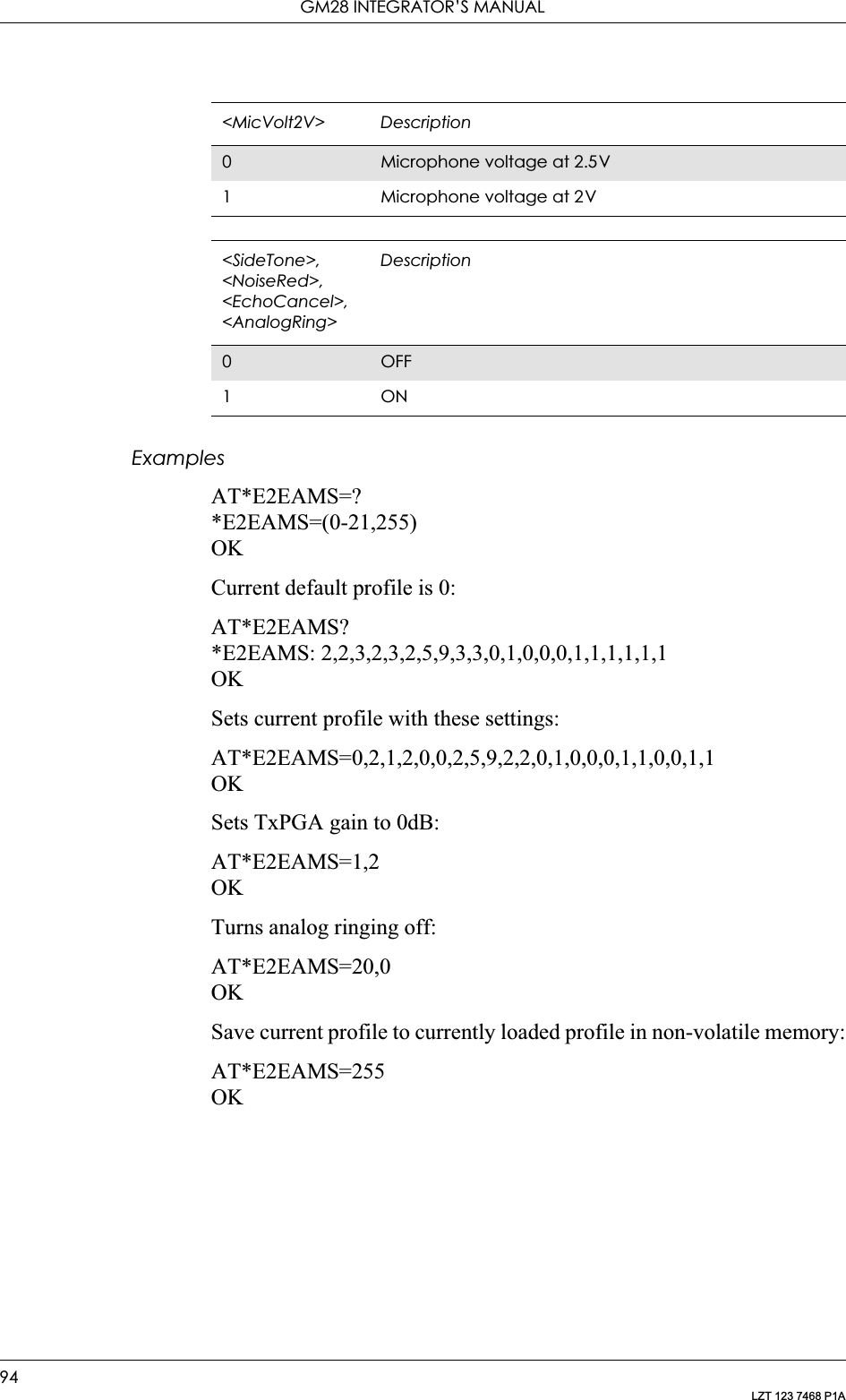
![89LZT 123 7468 P1A4. AudioAT*E2EAMS and AT*E2APR are new commands that replace the funtionality offered by the *EALR, *EAMS, *EARS and *ELAM commands. Use the new commands in new applications. The old commands are included for compatibility.4.1 AT*E2EAMS Ericsson M2M Audio Profile ModificationThis command allows the modification and configuration of the current audio profile. An audio profile is a set of data which uniquely defines the way in which the audio paths, gains, DSP algorithms and switch setting are configured. There are several audio profiles available in non-volatile storage, and the current profile can be modified by use of the AT*E2APR command.The AT*E2EAMS command allows the user to:Description Command Possible ResponsesRequest operation with audio profileAT*E2EAMS= <op>[,<TxPGA>,<RxPGA>,<SideToneGain>,<AuxInGain>,<MicInGain>,<TxAGC>,<Volume>,<MaxVolume>,<MicPath>,<SpkPath>,<TxPCM>,<RxPCM>,<HFAlgorithm>,<LocalAudio>,<TxGainLow>,<MicVolt2V>,<SideTone>,<NoiseRed>,<EchoCancel>,<AnalogRing>,][,<val>]]• ERROR•OKDisplay set profile AT*E2EAMS? • *E2EAMS: <TxPGA>,<RxPGA>,<SideToneGain>,<AuxInGain>,<MicInGain>,<TxAGC>,<Volume>,<MaxVolume>,<MicPath>,<SpkPath>,<TxPCM>,<RxPCM>,<HFAlgorithm>,<LocalAudio>,<TxGainLow>,<MicVolt2V>,<SideTone>,<NoiseRed>,<EchoCancel>,<AnalogRing>OK• ERRORShow if the command is supported AT*E2EAMS=? • *E2EAMS:(list of supported <op>s)• ERROR](https://usermanual.wiki/Sony/6220502-BV.Integrators-User-Manual/User-Guide-324170-Page-89.png)
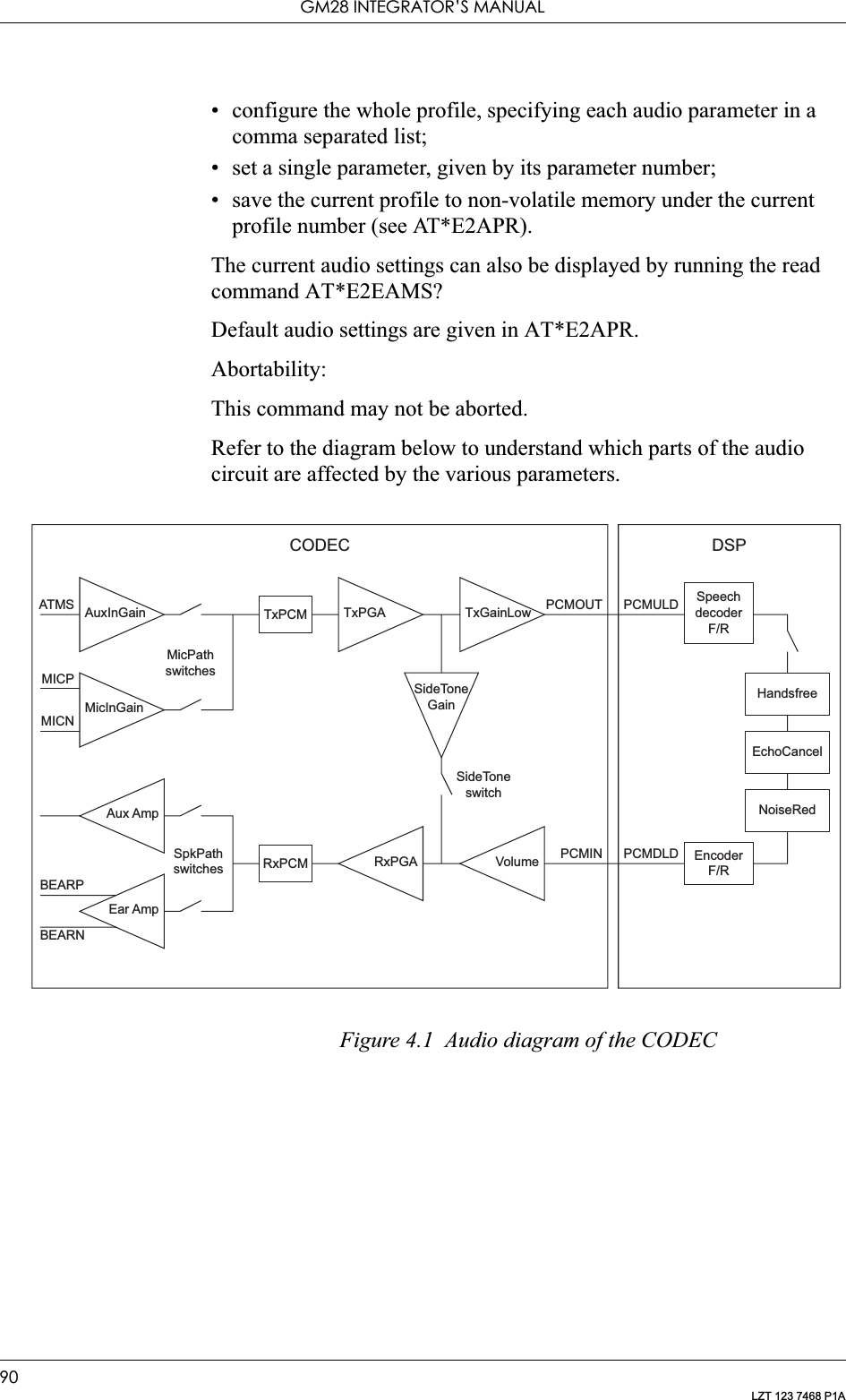
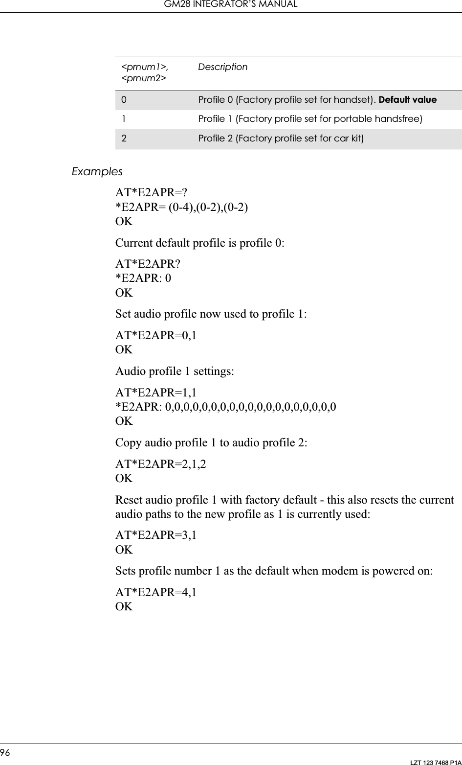
![4. AUDIO95LZT 123 7468 P1A4.2 AT*E2APR M2M Audio Profile ManipulationThis command allows the maniuplation and storage of the audio “profiles” stored in the MS. The requirement for the 2nd and 3rd parameters depend on the operation being carried out.Using the command you can:• Set one of the three audio profiles 0, 1 or 2 as the current profile. This will load the profile's settings from NVM and implement them.• Read one of the audio profiles. The current settings for the profile number defined will be displayed.• Copy all parameters from one profile into another.• Reset any of the profiles. This will reinstate the factory defaults for the profile:- 0 is the handset profile,- 1 is the portable handsfree profile,- 2 is the car kit profile.• Set a profile as the default profile on next power up.Description Command Possible ResponsesRequest operation with audio profileAT*E2APR= <op>[,<prnum1>[,<prnum2>]]•ERROR•OK• *E2APR: <TxPGA>,<RxPGA>,<SideToneGain>,<AuxInGain>,<MicInGain>,<TxAGC>,<Volume>,<MaxVolume>,<MicPath>,<SpkPath>,<TxPCM>,<RxPCM>,<HFAlgorithm>,<LocalAudio>,<TxGainLow>,<MicVolt2V>,<SideTone>,<NoiseRed>,<EchoCancel>,<AnalogRing>•OKDisplay currently set profile AT*E2APR? • *E2APR: current <prnum>• ERRORShows if the command is supported AT*E2APR=? • *E2APR: (list of supported <op>s), (list of supported <prnum1>s), (list of supported <prnum2>s)•ERROR<op> Description0Set profile <prnum1> to set as current1 Copy profile <prnum1> to <prnum2>2Read profile <prnum1> settings3 Reset profile <prnum1> to factory default4Set default profile as <prnum1>. Will store this as defautl profile in NVM, and use it as default from next power on](https://usermanual.wiki/Sony/6220502-BV.Integrators-User-Manual/User-Guide-324170-Page-95.png)
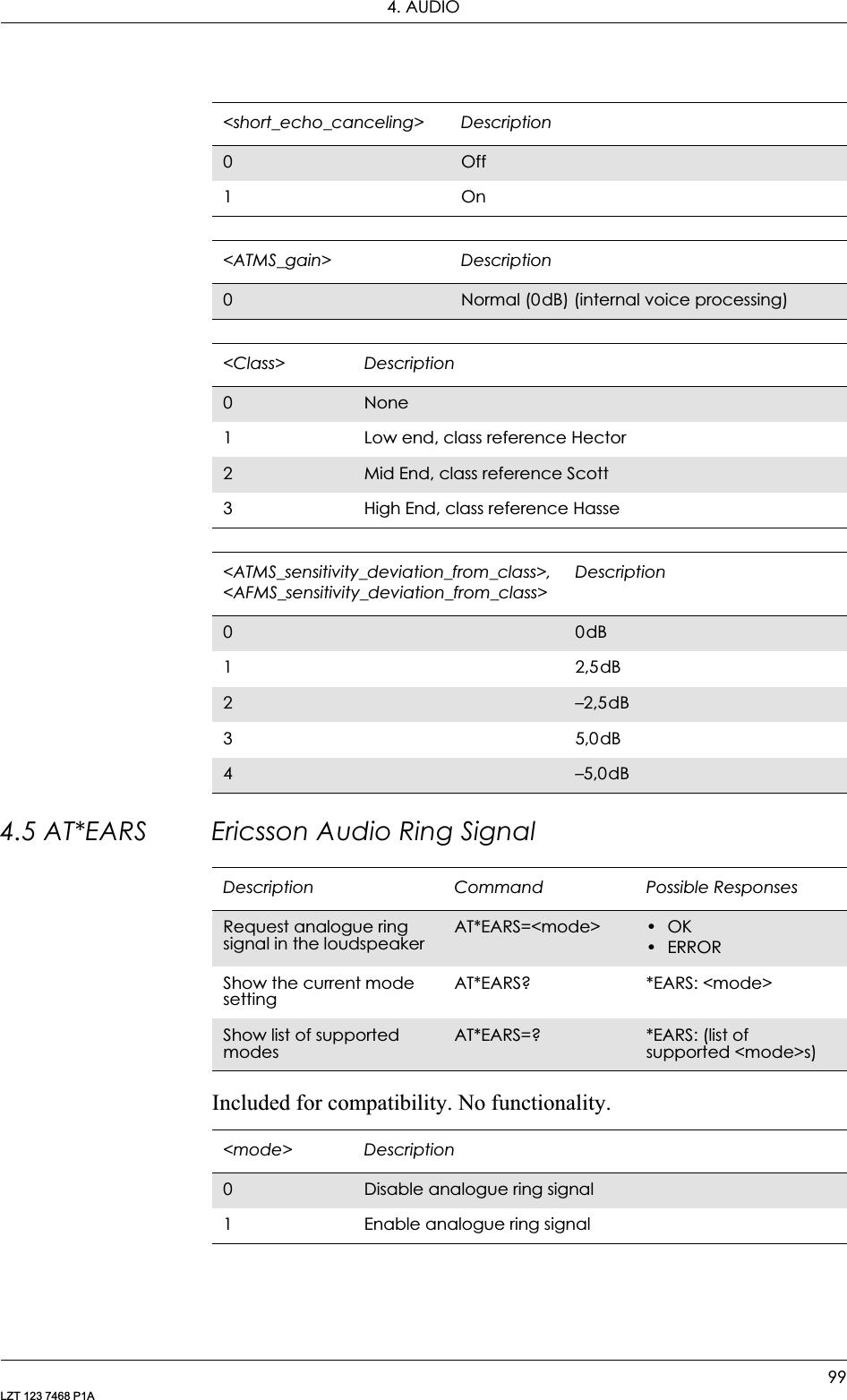
![4. AUDIO97LZT 123 7468 P1A4.3 AT*EALR Ericsson Audio Line RequestIncluded for compatibility. No functionality.Description Command Possible ResponsesRequest the audio lines (ATMS,AFMS) AT*EALR=<mode>[,<activation>[,<aud_status>]]• *EALR: <mode>,<activation>,<resp>•OK•ERRORShow the current settingAT*EALR? *EALR: <mode>,<activation>,<resp>Show list of supported parametersAT*EALR=? *EALR:(list of supported <mode>s, <activation>s and <aud_status>s parameters)<mode> Description0No request for ATMS or AFMS1 Request ATMS and not AFMS2Request AFMS and not ATMS3 Request ATMS and AFMS<activation> Description0Not direct activated audio accessory (e.g. cordless portable hands free) 1 Direct activated audio accessory (e.g. vehicle hands free)<aud_status> Description0No change of the audio status1 Audio hand over. Accessory hands over control of both the audio lines and the call to the phone2Audio demand. Accessory demands control of both the audio lines and the call<resp> Description0Disable ATMS and AFMS1 Enable ATMS and disable AFMS2Disable ATMS and enable AFMS3 Enable ATMS and AFMS](https://usermanual.wiki/Sony/6220502-BV.Integrators-User-Manual/User-Guide-324170-Page-97.png)
![GM28 INTEGRATOR’S MANUAL98LZT 123 7468 P1A4.4 AT*EAMS Ericsson Audio Mode SelectionIncluded for compatibility. No functionality.Description Command Possible ResponsesSets the audio mode for the applicationAT*EAMS=<internal_voice_alg>[,<noise_reduction>[,<side tone>[,<short_echo_canceling>[,<ATMS_gain>[,<class>[,<ATMS_sensitivity_deviation_from_class>[,<AFMS_sensitivity_deviation_from_class>]]]]]]]•OK•ERRORShow the current audio mode settingAT*EAMS? *EAMS:<internal_voice_alg >, <noise_reduction>, <side_tone>, <short_echo_canceling>,<AFMS_gain>,<class>,<ATMS_sensitivity_deviation_from_class>,<AFMS_sensitivity_deviation_from_class>Show list of supported servicesAT*EAMS=? *EAMS: (list of supported<internal_voice_alg >s, <noise_reduction>s, <side_tone>s, <short_echo_canceling>s,<AFMS_gain>s>,<class>s,<ATMS_sensitivity_deviation_from_class>s,<AFMS_sensitivity_deviation_from_class>s)<internal_voice_alg> Description0None1 Semi Duplex2Full Duplex (Note! the internal hands free algorithm in the MS contains echo cancelling)<noise_reduction> Description0Off1On<side_tone> Description0Off1On](https://usermanual.wiki/Sony/6220502-BV.Integrators-User-Manual/User-Guide-324170-Page-98.png)
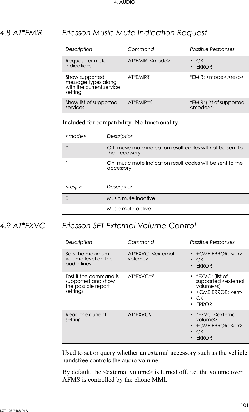
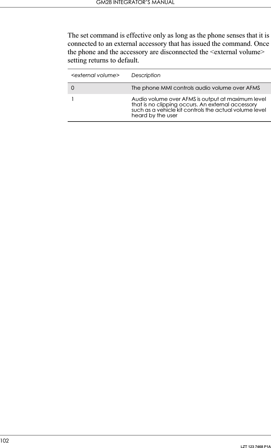
![GM28 INTEGRATOR’S MANUAL100LZT 123 7468 P1A4.6 AT*ELAM Ericsson Local Audio ModeIncluded for compatibility. No functionality.4.7 AT*EMIC Ericsson Microphone ModeIncluded for compatibility. No functionality.Description Command Possible ResponsesSet local audio mode AT*ELAM=<mic>[,<loudspeaker>]• *ELAM: <mic>,<loudspeaker> •OK•ERRORShow the current service settingAT*ELAM? *ELAM: <mic>,<loudspeaker> Show list of supported parametersAT*ELAM=? *ELAM: (list of supported <mic>s and <loudspeaker>s parameters)<mic> Description0Off1Microphone analogue<loudspeaker> Description0Off1 Loudspeaker analogueDescription Command Possible ResponsesEnables/disables the phone microphoneAT*EMIC=<mode> • +CME ERROR: <err>•OK•ERRORTest if the command is supported, show supported valuesAT*EMIC=? • *EMIC: (list of supported <mode>s)• +CME ERROR: <err>•OK•ERRORRead the current settingsAT*EMIC? • *EMIC: <mode>• +CME ERROR: <err>•OK•ERROR<mode> Description0Microphone is disabled (off)1 Microphone is enabled (on)](https://usermanual.wiki/Sony/6220502-BV.Integrators-User-Manual/User-Guide-324170-Page-100.png)
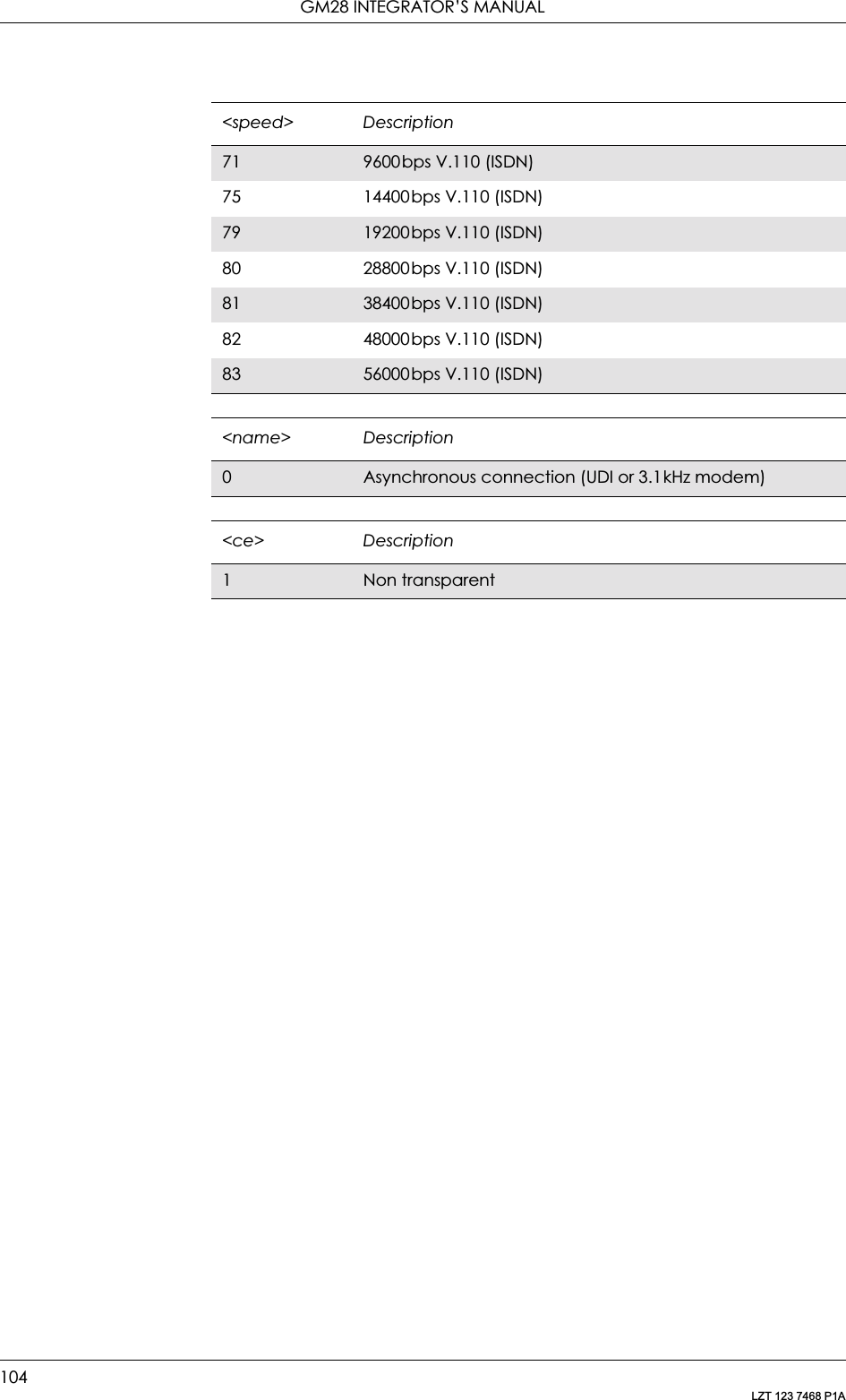
![103LZT 123 7468 P1A5. Data - CSD/HSCSDNote! Since the modem does not support V42bis compression the following commands have not been implemented:•AT+DS•AT+DR5.1 AT+CBST Select Bearer Service TypeSelects the bearer service <name> with data rate <speed>, and the connection element <ce> to be used when data calls are originated. Values may also be used during mobile terminated data call setup, especially in the case of single numbering scheme calls.Test command returns values supported by the TA as compound values.Description Command Possible ResponsesSelect bearer service typeAT+CBST=[<speed>,[<name>,[<ce>]]]•OK •ERRORRead the command AT+CBST? • +CBST: <speed>,<name>,<ce>•OK •ERRORTest if the command is supportedAT+CBST=? • +CBST: (list of supported <speed>s,list of supported <name>s, list of supported <ce>s)•OK •ERROR<speed> Description0Auto selection of baud rate4 2400bps V.22bis64800bps V.327 9600bps V.3212 9600bps V.3415 19200bps V.3468 2400bps V.110 (ISDN)70 4800bps V.110 (ISDN)](https://usermanual.wiki/Sony/6220502-BV.Integrators-User-Manual/User-Guide-324170-Page-103.png)
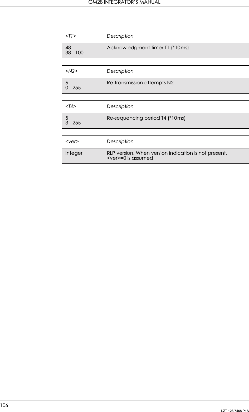
![5. DATA - CSD/HSCSD105LZT 123 7468 P1A5.2 AT+CRLP Radio Link ProtocolRadio link protocol (RLP) parameters used when non-transparent data calls are originated may be altered with this command. Available command subparameters depend on the RLP versions implemented by the device (e.g. <ver> may not be available if device supports only versions 0 and 1).Read command returns current settings for each supported RLP version <verx>. Only RLP parameters applicable to the corresponding <verx> are returned.Test command returns values supported by the TA as a compound value. If ME/TA supports several RLP versions <verx>, the RLP parameter value ranges for each <verx> are returned in a separate line.Description Command Possible ResponsesSet radio link protocolAT+CRLP=[<iws>[,<mws>[,<T1>[,<N2>[,<ver>[, <T4>]]]]]]•OK •ERRORRead the commandAT+CRLP? • +CRLP: <iws>,<mws>,<T1>,<N2>[,<ver1> [,<T4>]][<CR><LF>•+CRLP: <iws>,<mws>,<T1>,<N2>[,<ver2> [,<T4>]][...]]•OK •ERRORTest if the command is supportedAT+CRLP=? • +CRLP: (list of supported <iws>s), (list of supported <mws>s),(list of supported <T1>s),(list of supported<N2>s)[,<ver1>[,(list of supported <T4>s)]] [<CR><LF>+CRLP: (list of supported <iws>s), (list of supported <mws>s), (list of supported <T1>s), (list of supported <N2>s)[,<ver2>[,(list of supported <T4>s)]][...]]•OK •ERROR<iws> Description1200 - 496IWF to MS window size<mws> Description1200 - 496MS to IWF window size](https://usermanual.wiki/Sony/6220502-BV.Integrators-User-Manual/User-Guide-324170-Page-105.png)
![107LZT 123 7468 P1A6. Data - GPRS6.1 AT+CGACT PDP Context Activate or DeactivateUsed to activate or deactivate the specified PDP context(s).After the command has completed, the MS remains in V.250 command state. If the MS is already in the requested state, the command is ignored and OK is returned. If the requested state cannot be achieved, ERROR or +CME: ERROR is returned. If the MS is not attached to the GPRS service when the activation form of the command is executed, the MS first performs a GPRS attach and then attempts to activate the specific contexts.If no <cid>s are specified the activation form of the command activates all defined contexts.If no <cid>s are specified the deactivation form of the command deactivates all active contexts.Description Command Possible ResponsesActivate or deactivate the specified PDP context(s)+CGACT=[<state> [,<cid>[,<cid>[,…]]]]• +CME ERROR: <err>•OK•ERRORRead the command +CGACT? • +CGACT: <cid>, <state>[<CR><LF>+CGACT: <cid>, <state>[...]]•OK•ERRORTest if the command is supported+CGACT=? • +CGACT: (list of supported <state>s)•OK•ERROR<state> Description0PDP context activation deactivated1 PDP context activation activated<cid> DescriptionInteger type A numeric parameter which specifies a specific PDP context definition](https://usermanual.wiki/Sony/6220502-BV.Integrators-User-Manual/User-Guide-324170-Page-107.png)
![GM28 INTEGRATOR’S MANUAL108LZT 123 7468 P1A6.2 AT+CGATT GPRS Attach or DetachUsed to attach the MS to, or detach the MS from, the GPRS/packet domain service. After the command has completed, the MS remains in V.250 command state. If the MS is already in the requested state, the command is ignored and the OK response is returned. If the requested state cannot be achieved, an ERROR or +CME ERROR response is returned. Extended error responses (enabled by the +CMEE command) are listed under “+CME ERROR (Mobile Equipment Error Code)”, page 55.Any active PDP contexts will be automatically deactivated when the attachment state changes to detached.Note! This command has the characteristics of both the V.250 action and parameter commands. Hence it has the read form in addition to the execution/set and test forms.Description Command Possible ResponsesAttach or detach MS to the GPRS/packet domain/packet domain service+CGATT=[<state>] • +CME ERROR: <err>•OK•ERRORRead the command +CGATT? • +CGATT: <state>•OK•ERRORTest if the command is supported+CGATT=? • +CGATT: (list of supported <state>s)•OK•ERROR<state> Description0Detached1 Attached](https://usermanual.wiki/Sony/6220502-BV.Integrators-User-Manual/User-Guide-324170-Page-108.png)
![6. DATA - GPRS109LZT 123 7468 P1A6.3 AT+CGDATA Enter Data StateCauses the MS to perform whatever actions are necessary to establish communication between the TE and the network using one or more GPRS/packet domain PDP types. This may include performing a GPRS/packet domain attach and one or more PDP context activations.Description Command Possible ResponsesEstablish GPRS/packet domain connection+CGDATA=[<L2p>,[cid[,cid>[,…]]]]•CONNECT•ERROR•OK•ERRORTest if the command is supported+CGDATA=? • +CGDATA: (list of supported <L2P>s)•OK•ERROR<L2P> DescriptionPPP Point-to-point protocol for a PDP such as IP](https://usermanual.wiki/Sony/6220502-BV.Integrators-User-Manual/User-Guide-324170-Page-109.png)
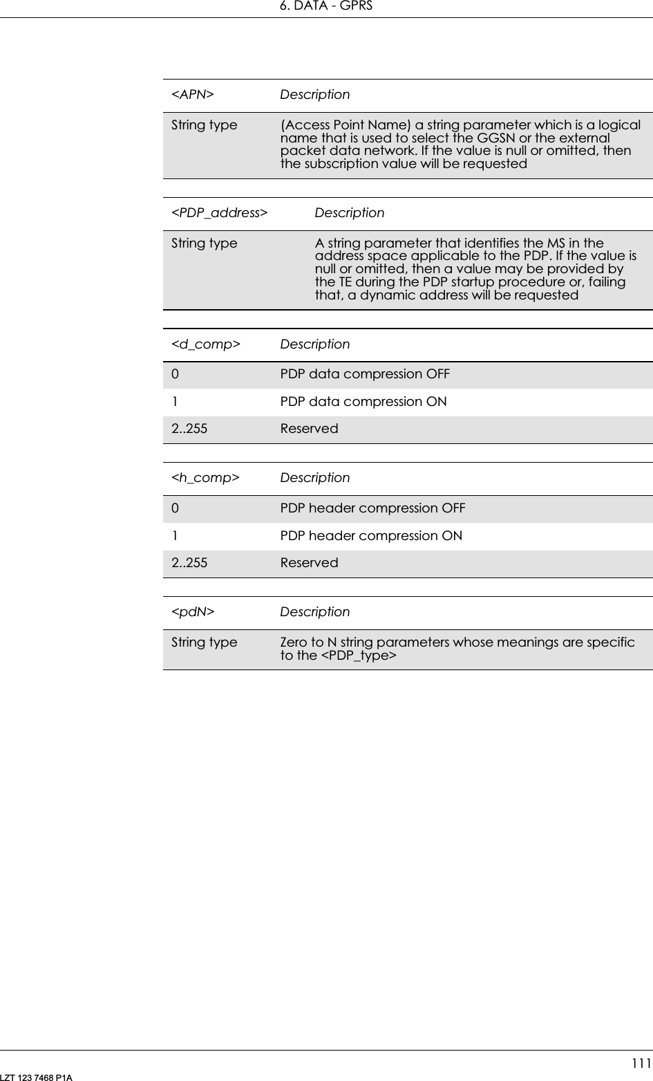
![GM28 INTEGRATOR’S MANUAL110LZT 123 7468 P1A6.4 AT+CGDCONT Define PDP ContextSpecifies PDP context parameter values for a PDP context identified by the (local) context identification parameter, <cid>.Description Command Possible ResponsesSelect PDP context parameters+CGDCONT=[<cid> [,<PDP_type> [,<APN> [,<PDP_addr> [,<d_comp> [,<h_comp> [,<pd1> [,…[,pdN]]]]]]]]]• +CME ERROR: <err>•OK•ERRORRead the command+CGDCONT? • +CGDCONT: <cid>, <PDP_type>,<APN>, <PDP_addr>,<d_comp>, <h_comp>[,<pd1>[,…[,pdN]]] [<CR><LF>+CGDCONT: <cid>, <PDP_type>,<APN>, <PDP_addr>,<d_comp>, <h_comp>[,<pd1>[,…[,pdN]]] [...]]•OK•ERRORTest if the command is supported+CGDCONT=? • +CGDCONT: (range of supported <cid>s), <PDP_type>,,,(list of supported <d_comp>s),(list of supported <h_comp>s)[,(list of supported <pd1>s)[,…[,(list of supported <pdN>s)]]] [<CR><LF>+CGDCONT: (range of supported <cid>s), <PDP_type>,,,(list of supported <d_comp>s),(list of supported <h_comp>s)[,(list of supported <pd1>s)[,…[,(list of supported <pdN>s)]]] [...]]•OK•ERROR<cid> DescriptionInteger type (PDP Context Identifier) a numeric parameter which specifies a particular PDP context definition. The parameter is local to the TE-MS interface and is used in other PDP context-related commands. The range of permitted values (minimum value = 1) is returned by the test form of the command1-10 Supported values. Ericsson specific<PDP_type> DescriptionIP Internet Protocol (IETF STD 5)](https://usermanual.wiki/Sony/6220502-BV.Integrators-User-Manual/User-Guide-324170-Page-110.png)
![GM28 INTEGRATOR’S MANUAL112LZT 123 7468 P1A6.5 AT+CGEREP GPRS Event ReportingEnables or disables the sending of unsolicited result codes, +CGEV: XXX from MS to TE in the case of certain events occurring in the GPRS/packet domain MS or the network.Description Command Possible ResponsesSet command +CGEREP=[<mode>[,<bfr>]]• +CME ERROR: <err>•OK•ERRORRead the command +CGEREP? • +CGEREP: <mode>,<bfr>•OK•ERRORTest if the command is supported+CGEREP=? • +CGEREP: (list of supported <mode>s),(list of supported <bfr>s)•OK•ERROR<mode> Description0Buffer unsolicited result codes in the MS. No codes are forwarded to the TE1 Discard unsolicited result codes when MS-TE link is reserved; otherwise forward them directly to the TE<bfr> Description0MS buffer of unsolicited result codes defined within this command is cleared when <mode> 1 or 2 is entered](https://usermanual.wiki/Sony/6220502-BV.Integrators-User-Manual/User-Guide-324170-Page-112.png)
![6. DATA - GPRS113LZT 123 7468 P1A6.6 AT+CGPADDR Show PDP AddressReturns a list of PDP addresses for the specified context identifiers. The test command returns a list of defined <cid>s.Description Command Possible ResponsesShow PDP addresses for specified CIDs+CGPADDR=[<cid> [,<cid> [,…]]]•+CGPADDR: <cid>,<PDP_addr>[<CR><LF>+CGPADDR: <cid>,<PDP_addr>[...]]•OK•ERRORTest if the command is supported+CGPADDR=? • +CGPADDR: (list of defined <cid>s)•OK•ERROR<cid> DescriptionInteger type Parameter which specifies a particular PDP context definition (see +CGDCONT command). If no <cid> is specified, the addresses for all defined contexts are returned<PDP_address> DescriptionString type A string that identifies the MS in the address space applicable to the PDP. The address may be static or dynamic. For a static address, it will be the one set by the +CGDCONT command when the context was defined. For a dynamic address it will be the one assigned during the last PDP context activation that used the context definition referred to by <cid>. <PDP_address> is omitted if none is available](https://usermanual.wiki/Sony/6220502-BV.Integrators-User-Manual/User-Guide-324170-Page-113.png)
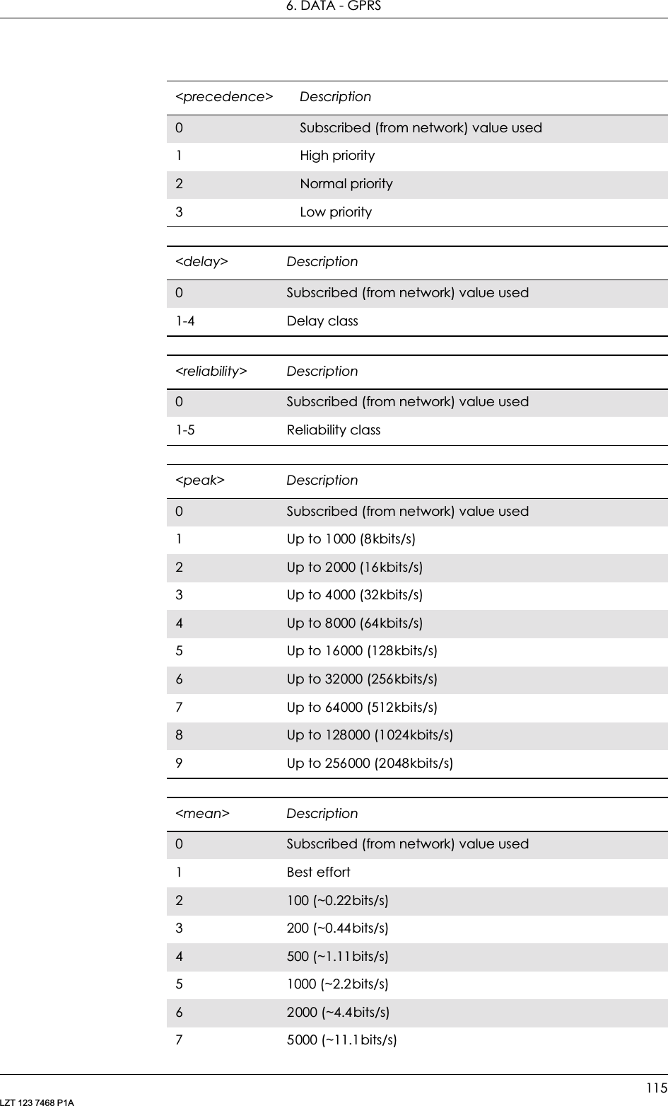
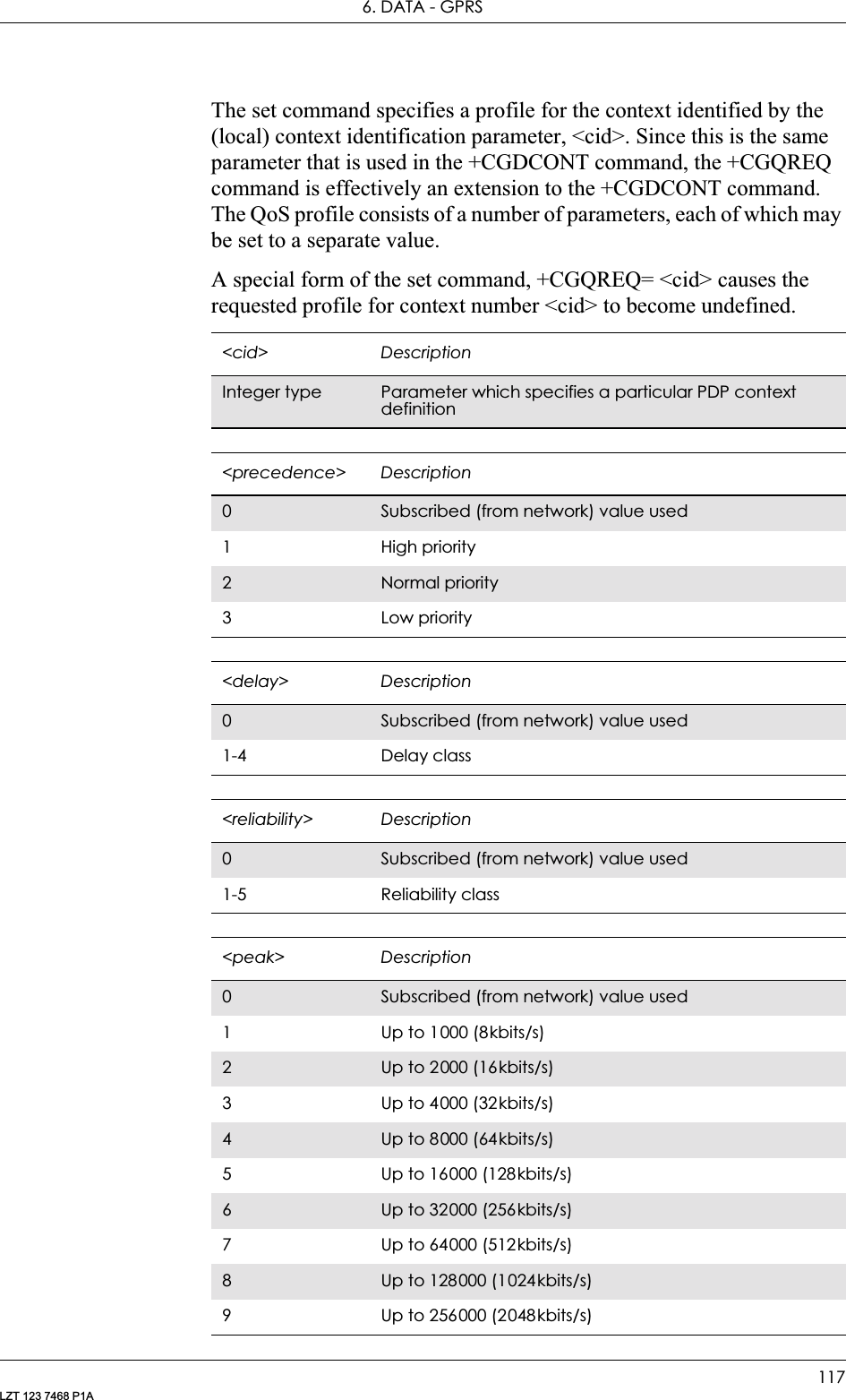
![GM28 INTEGRATOR’S MANUAL114LZT 123 7468 P1A6.7 AT+CGQMIN Quality of Service Profile (Minimum Acceptable)Allows the TE to specify a minimum acceptable profile which is checked by the MS against the negotiated profile returned in the Activate PDP Context Accept message.The set command specifies a profile for the context identified by the (local) context identification parameter, <cid>. Since this is the same parameter that is used in the +CGDCONT command, the +CGQMIN command is effectively an extension to the +CGDCONT command. The QoS profile consists of a number of parameters, each of which may be set to a separate value.A special form of the set command, +CGQMIN=<cid> causes the minimum acceptable profile for context number <cid> to become undefined. In this case no check is made against the negotiated profile.Description Command Possible ResponsesSet minimum acceptable profile+CGQMIN=[<cid> [,<precedence> [,<delay> [,<reliability> [,<peak> [,<mean>]]]]]]• +CME ERROR: <err>•OK•ERRORRead the command+CGQMIN? • +CGQMIN: <cid>, <precedence>, <delay>, <reliability>, <peak>, <mean>[<CR><LF>+CGQMIN: <cid>, <precedence>, <delay>, <reliability>, <peak>, <mean>[…]]•OK•ERRORTest if the command is supported+CGQMIN=? • +CGQMIN: <PDP_type>, (list of supported <precedence>s), (list of supported <delay>s), (list of supported <reliability>s) , (list of supported <peak>s), (list of supported <mean>s)[<CR><LF>+CGQMIN: <PDP_type>, (list of supported <precedence>s), (list of supported <delay>s), (list of supported <reliability>s) , (list of supported <peak>s), (list of supported <mean>s)[…]]•OK•ERROR<cid> DescriptionInteger type Parameter which specifies a particular PDP context definition](https://usermanual.wiki/Sony/6220502-BV.Integrators-User-Manual/User-Guide-324170-Page-114.png)
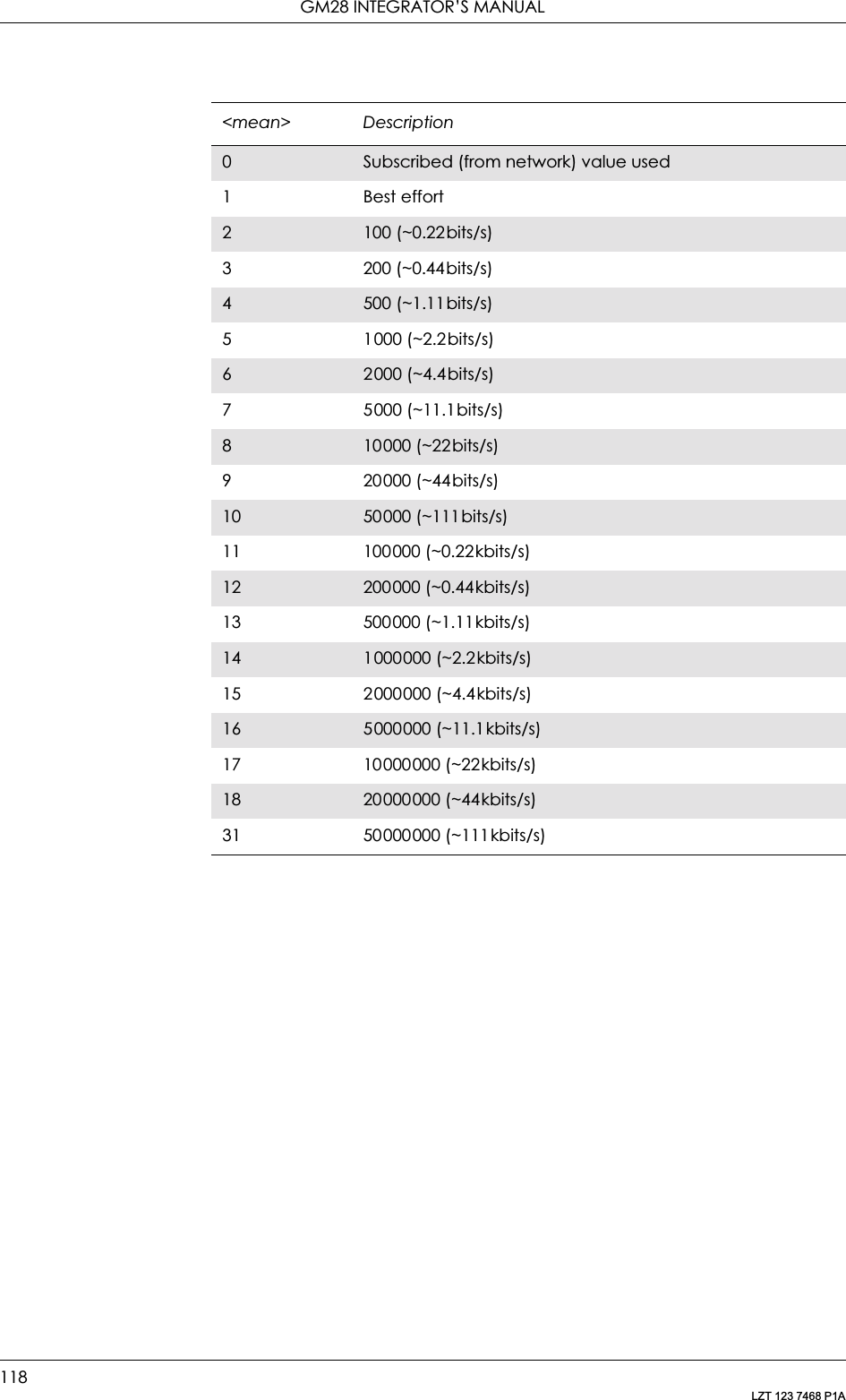
![GM28 INTEGRATOR’S MANUAL116LZT 123 7468 P1A6.8 AT+CGQREQ Quality of Service Profile (Requested)Allows the TE to specify a quality of service profile that is used when the MS sends an activate PDP context request message to the network.810000 (~22bits/s)9 20000 (~44bits/s)10 50000 (~111bits/s)11 100000 (~0.22kbits/s)12 200000 (~0.44kbits/s)13 500000 (~1.11kbits/s)14 1000000 (~2.2kbits/s)15 2000000 (~4.4kbits/s)16 5000000 (~11.1kbits/s)17 10000000 (~22kbits/s)18 20000000 (~44kbits/s)31 50000000 (~111kbits/s)<mean> DescriptionDescription Command Possible ResponsesSet quality of service profile+CGQREQ=[<cid> [,<precedence> [,<delay> [,<reliability> [,<peak> [,<mean>]]]]]]• +CME ERROR: <err>•OK•ERRORRead the command+CGQREQ? • +CGQREQ: <cid>, <precedence>, <delay>, <reliability>, <peak>, <mean>[<CR><LF>+CGQREQ: <cid>, <precedence>, <delay>, <reliability>, <peak>, <mean>[…]]•OK•ERRORTest if the command is supported+CGQREQ=? • +CGQREQ: <PDP_type>,(list of supported <precedence>s),(list of supported <delay>s),(list of supported <reliability>s),(list of supported <peak>s),(list of supported <mean>s) [<CR><LF>+CGQREQ: <PDP_type>, (list of supported <precedence>s), (list of supported <delay>s),(list of supported <reliability>s),(list of supported <peak>s),(list of supported <mean>s)[…]]•OK•ERROR](https://usermanual.wiki/Sony/6220502-BV.Integrators-User-Manual/User-Guide-324170-Page-116.png)
![6. DATA - GPRS119LZT 123 7468 P1A6.9 AT+CGREG GPRS Network Registration StatusControls the presentation of an unsolicited result code +CGREG: <stat> when <n>=1 and there is a change in the GPRS/packet domain network registration status of the MS, or code +CGREG: <stat>[,<lac>,<ci>] when <n>=2 and there is a change of the network cell.Note! If the GPRS/Packet Domain MS also supports circuit mode services, the +CGREG command and +CGREG: result code apply to the registration status and location information for those services.Description Command Possible ResponsesSet command AT+CGREG=[<n>] • +CME ERROR: <err>•OK•ERRORRead the current settingsAT+CGREG? • +CGREG: <n>,<stat>[,<lac>,<ci>]• +CME ERROR: <err>•OK•ERRORTest if the command is supportedAT+CGREG=? • +CGREG: (list of supported <n>s)•OK•ERROR<n> Description0Disable network registration unsolicited result code1 Enable network registration unsolicited result code2Enable network registration and location information unsolicited result code<stat> Description0Not registered, MS is not searching for a new operator to register with1 Registered, home network2Not registered, but MS is searching for a new operator to register with3 Registration denied4Unknown5 Registered, roaming<lac> DescriptionString type Two byte location area code in hexadecimal format](https://usermanual.wiki/Sony/6220502-BV.Integrators-User-Manual/User-Guide-324170-Page-119.png)
![GM28 INTEGRATOR’S MANUAL120LZT 123 7468 P1A6.10 AT+CGSMS Select Service for MO SMS MessagesUsed to specify the service or service preference that the MS will use to send MO SMS messages. The read command returns the currently selected service or service preference.<ci> DescriptionString type Two byte cell ID in hexadecimal formatDescription Command Possible ResponsesSet service or service preference+CGSMS=[<service>] •OK•ERRORRead the command +CGSMS? • +CGSMS: <service>•OK•ERRORTest if the command is supported+CGSMS=? • +CGSMS: (list of available <service>s)•OK•ERROR<services> Description2GPRS/packet domain preferred (use circuit switched if GPRS/packet domain not available)3 Circuit switched preferred (use GPRS/packet domain if circuit switched not available)](https://usermanual.wiki/Sony/6220502-BV.Integrators-User-Manual/User-Guide-324170-Page-120.png)
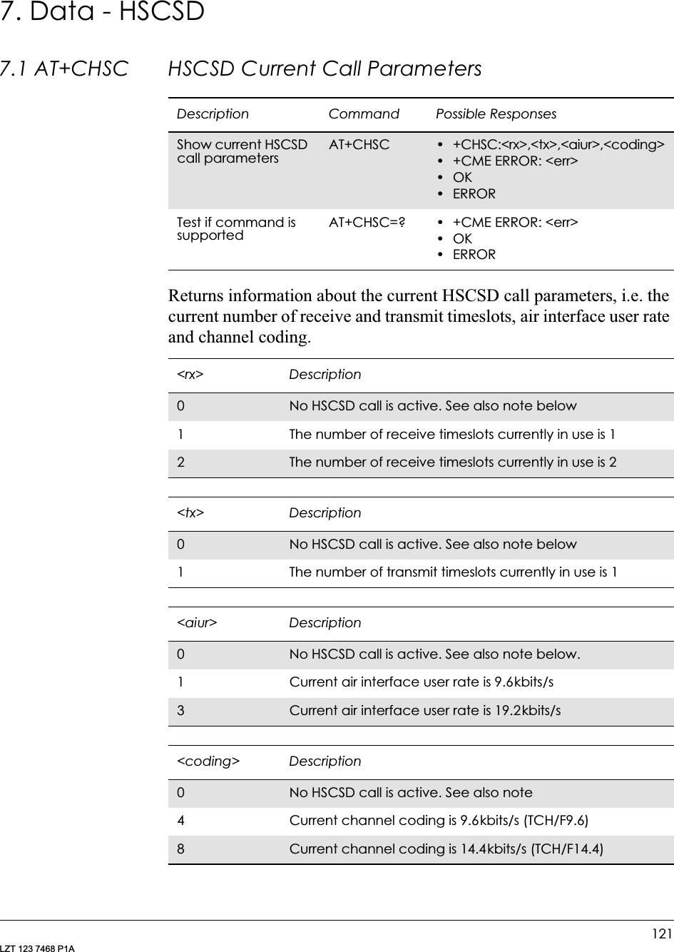
![7. DATA - HSCSD123LZT 123 7468 P1A7.3 AT+CHSN HSCSD Non Transparent Call ConfigurationControls parameters for non-transparent HSCSD calls. Changing <topRx> or <codings> during a call does not affect the current call. Changing <wAiur> or <wRx> affects the current call only if <topRx> was non-zero when the call was established. When using the command in this way it comes in the “action” command category. This is what is referred to as user initiated up- and down-grading in GSM 02.34 and GSM 03.34.Note! Recommended value for parameter <speed> in AT+CBST is 0.Description Command Possible ResponsesSet HSCSD configuration. This command is also used during a call if new <wAiur> and/or <wRx> are/is desiredAT+CHSN=[<wAiur>[,<wRx>[,<topRx>[,<codings>]]]]• +CME ERROR: <err>•OK•ERRORShow current non-transparent HSCSD settingAT+CHSN? • +CHSN: <wAiur>, <wRx>, <topRx>, <codings>• +CME ERROR: <err>•OK•ERRORTest if command is supported and show parameter rangesAT+CHSN=? • +CHSN: (list of supported <wAiur>s), (list of supported <wRx>s), (list of supported <topRx>s), (list of supported <codings>s)• +CME ERROR: <err>•OK•ERROR<wAiur> Description0TA/ME shall calculate a proper number of receive timeslots from currently selected fixed network user rate (<speed> parameter from +CBST command, and <codings>, and <wRx> (or <maxRx> from +CHSD command if <wRx>=0)1 Wanted air interface user rate is 9.6kbit/s2Wanted air interface user rate is 14.4kbit/s3 Wanted air interface user rate is 19.2kbit/s4Wanted air interface user rate is 28.8kbit/s](https://usermanual.wiki/Sony/6220502-BV.Integrators-User-Manual/User-Guide-324170-Page-123.png)
![GM28 INTEGRATOR’S MANUAL124LZT 123 7468 P1A7.4 AT+CHSR HSCSD Parameters ReportWith this command enabled, the intermediate result code +CHSR: <rx>,<tx>,<aiur>,<coding> is returned (from TA to TE) when an HSCSD call is being set up. The result code represents the current (negotiated or renegotiated) HSCSD parameters. If enabled, the intermediate result code is transmitted at the point of the call setup negotiation, where the ME/TA has determined what type of HSCSD connection will be used. Result code transmission is done after possible service (CR), error control (+ER), and/or compression (+DR) reporting, <wRx> Description0TA/ME shall calculate a proper number of receive timeslots from currently selected <wAiur> and <codings> See note below1 Wanted number of receive timeslots is 12Wanted number of receive timeslots is 2<topRx> Description0Indicates that the user is not going to change <wAiur> and /or <wRx> during the next call1 Top value for <wRx> that user is going to request during the next established non-transparent HSCSD call is 1 2Top value for <wRx> that user is going to request during the next established non-transparent HSCSD call is 2<codings> Description4Indicates that the accepted channel coding for the next established non-transparent HSCSD call is 9.6kbit/s onlyDescription Command Possible ResponsesSet HSCSD parameters reporting on or offAT+CHSR=[<mode>] • +CME ERROR: <err>•OK•ERRORShow current setting AT+CHSR? • +CHSR: <mode>• +CME ERROR: <err>•OK•ERRORTest if command is supported and show parameter rangeAT+CHSR=? • +CHSR: (list of supported <modes>s)• +CME ERROR: <err>•OK•ERROR](https://usermanual.wiki/Sony/6220502-BV.Integrators-User-Manual/User-Guide-324170-Page-124.png)
![7. DATA - HSCSD125LZT 123 7468 P1Abut before possible TE-TA rate (+ILRR) reporting and before the intermediate result code CONNECT is transmitted. The format of the intermediate result code is:+CHSR: <rx>,<tx>,<aiur>,<coding>For the value definitions, refer to “AT+CHSC HSCSD Current Call Parameters”, page 121. For instance, for a non-transparent HSCSD call, result code ‘CHSR: 2, 1, 4, 8’ means that the call has two timeslots downlink, one timeslot uplink, the air interface user rate is 28.8 kbits/s and the used channel coding isTCH/F14.4.Itermediate Result Codes:+CHSR: <rx>,<tx>,<aiur>,<coding>7.5 AT+CHSU HSCSD Automatic User Initiated UpgradingEnables or disables the HSCSD automatic user-initiated upgrade.<mode> Description0Disable reporting1 Enable reportingDescription Command Possible ResponsesSet HSCSD automatic user initiated upgrading on or offAT+CHSU=[<mode>] •OK•ERRORShow current setting AT+CHSU? • +CHSU=<mode>•OK•ERRORTest if command is supported and show parameter rangeAT+CHSU=? • +CHSU: (list of supported <modes>s)•OK•ERROR<mode> Description0Disable use of UP bit for upgrading. Default value1 Enable use of UP bit for upgrading](https://usermanual.wiki/Sony/6220502-BV.Integrators-User-Manual/User-Guide-324170-Page-125.png)

![129LZT 123 7468 P1A9. Identification9.1 AT Attention CommandThis command is used to determine the presence of an MS. If the MS supports AT commands, it returns an OK final result code.9.2 AT&F Set to Factory Defined ConfigurationThis command instructs the DCE to set all parameters to default values specified by the manufacturer, which may take in consideration hardware configuration and other manufacturer defined criteria.9.3 AT&W Store User ProfileThis command stores the current user profile in non-volatile memory.Description Command Possible ResponsesChecks the communication between the MS and applicationAT •OK• +CME ERROR <err>Description Command Possible ResponsesExecute AT&F •OK•ERRORShow if supported and list available parameter rangeAT&F=? &F: (list of supported <profile>s)Description Command Possible ResponsesStores the current user profile to non volatile memoryAT&W=[<pr>] or AT&W[<pr>]•OK•ERRORShow if the command is supportedAT&W=? &W: (list of supported <pr>s)< pr> Description0Stores current settings in User Profile 0](https://usermanual.wiki/Sony/6220502-BV.Integrators-User-Manual/User-Guide-324170-Page-129.png)
![GM28 INTEGRATOR’S MANUAL130LZT 123 7468 P1A9.4 AT* List all Supported AT CommandsLists all the commands supported by the MS.9.5 AT+CGMI Read MS Manufacturer IdentificationCauses the MS to return one or more lines of information text.9.6 AT+CGMM Read MS Model IdentificationCauses the MS to return one or more lines of information text <model>, determined by the MS manufacturer. It is intended to permit the user of the ITAE/ETAE to identify the specific model of the MS to which it is connected. Typically the text will consist of a single line containing the name of the product, but manufacturers may choose to provide more information if desired.Description Command Possible ResponsesList all implemented AT commandsAT* <AT Command1> [<CR> <LF><AT Command2>[…]]/<AT Command1> [<CR> <LF><AT Command2>[…]]Description Command Possible ResponsesRequest manufacturer identificationAT+CGMI •<manufacturer>• +CME ERROR: <err>Show if the command is supportedAT+CGMI=? • OK•ERROR<manufacturer> DescriptionSony Ericsson This company’s name is displayedDescription Command Possible ResponsesRequest the model identificationAT+CGMM •<model type><model name>• +CME ERROR: <err>Show if the command is supportedAT+CGMM=? • OK•ERROR<model type> DescriptionString type A unique ASCII character/digit string, always 10 characters long. Spaces are used when the number of characters/digits is less than 10](https://usermanual.wiki/Sony/6220502-BV.Integrators-User-Manual/User-Guide-324170-Page-130.png)
![9. IDENTIFICATION131LZT 123 7468 P1A9.7 AT+CGMR Read MS Revision IdentificationThis command causes the MS to return a string containing information about the software version.9.8 AT+CGSN Read MS Product Serial Number IdentificationThis command causes the MS to return the IMEI (International Mobile station Equipment Identity), which identifies the individual ME.9.9 ATI Identification InformationThis command causes the DCE to transmit one or more lines of text, followed by a final result code. As an option, <value> can be used to select from among multiple types of identifying information as shown in the table below.<model name> DescriptionString type Model name for the transceiver unit, for example, GM28Description Command Possible ResponsesRequest MS revision identification stringAT+CGMR •<revision>• +CME ERROR: <err>Show if the command is supportedAT+CGMR=? • OK•ERROR<revision> DescriptionString type An ASCII string containing date (year, month, day, hour, minute) plus KRC number.Example: 9710051610 CXC125112Description Command Possible ResponsesRequest product serial numberAT+CGSN •<sn>• +CME ERROR: <err>Show if the command is supportedAT+CGSN=? • OK•ERROR<sn> DescriptionString The IMEISV, which is the IMEI (International Mobile station Equipment Identity; refer GSM 03.03) number of the ME and the software version number. Text shall not contain the sequence 0<CR> or OK<CR>Description Command Possible ResponsesExecute ATI[<value>] <information>](https://usermanual.wiki/Sony/6220502-BV.Integrators-User-Manual/User-Guide-324170-Page-131.png)
![133LZT 123 7468 P1A10. Interface10.1 AT+CPIN PIN ControlSee 3.23, AT+CPIN PIN Control10.2 AT&C Circuit 109 (DCD) ControlDetermines the behaviour of the carrier detect.10.3 AT&D Circuit 108 (DTR) ResponseControls all actions initiated by data terminal ready from DTE.Description Command Possible ResponsesSet behavior of carrier detectAT&C[<value>] OKERROR<value> Description0DCD always on1 DCD follows the connection. Default valueDescription Command Possible ResponsesControl actions from DTEAT&D[<value>] OKERROR<value> Description0Ignore. Default value1 When in on-line data mode, switch to on-line command mode. For all other states, see <value>=22Disconnect and switch to off-line command mode](https://usermanual.wiki/Sony/6220502-BV.Integrators-User-Manual/User-Guide-324170-Page-133.png)
![GM28 INTEGRATOR’S MANUAL134LZT 123 7468 P1A10.4 AT&S Circuit 107 (DSR) ResponseDetermines the behaviour of the data set ready signal.10.5 AT+WS46 Mode SelectionAllows an accessory to query and control the cellular protocol mode of the phone.Description Command Possible ResponsesSet behaviour of data set readyAT&S[<value>] •OK•ERROR<value> Description0DSR always on1 DSR on in data mode. DSR off in command mode. Default valueDescription Command Possible ResponsesSets the cellular protocol modeAT+WS46=n •OK•ERRORQueries the current cellular protocol modeAT+WS46? • <n> OK•ERRORQueries the possible cellular protocol modesAT+WS46=? • (list of supported <n>s) OK•ERROR<n> parameter Description12 This value is used for GSM at 900 MHz., DCS-1900, and PCS-1900 phones](https://usermanual.wiki/Sony/6220502-BV.Integrators-User-Manual/User-Guide-324170-Page-134.png)
![10. INTERFACE135LZT 123 7468 P1A10.6 ATE Command EchoThe setting of this parameter determines whether or not the DCE echoes characters received from the DTE during command state and online command state.10.7 ATV DCE Response FormatSelect either descriptive or numeric response codes. The ATV command sets the verbose numeric response codes and strips off the <S3><S4> additions to the command response.Description Command Possible ResponsesRequest Command EchoATE[<value>]ATE=[<value>]•OK•ERRORShow the current settingATE? <value>Show if the command is supportedATE=? E: (list of supported <value>s)<value> Description0DCE does not echo characters during command state and online command state1 DCE echoes characters during command state and online command state. Default valueDescription Command Possible ResponsesSet DCE response formatATV[=]<value> •OK•ERRORRead the current settingATV? V: <value>Show if the command is supportedATV=? V: (list of supported <value>s)<value> Description0Display numeric result codes1 Display verbose result codes. Default value](https://usermanual.wiki/Sony/6220502-BV.Integrators-User-Manual/User-Guide-324170-Page-135.png)
![10. INTERFACE137LZT 123 7468 P1ACommands included on the same command line as the Z command will be ignored.10.9 AT+CMUX Switch to 07.10 Multiplex ProtocolSI C25-68003The command is used to turn on the multiplexer. Only “no transparency is supported”. The parameter <k> is not used.The default values for the parameters below are for “no transparency” and “only UIH frames used”.<profile > Description0Select the user profile to restoreDescription Command Possible ResponsesSwitch to 07.10 AT+CMUX=<transparency>[,<subset>[,<port_speed>[,<N1>[,<T1>[,<N2>[,<T2>[,<T3>[,<k>]]]]]]]]+CME ERROR: <err>Returns current setting for multiplexerAT+CMUX? • +CMUX:<transparency>,<subset>,<port_speed>,<N1>,<T1>,<N2>,<T2>,<T3>[,<k>]• +CME ERROR: <err>Show list of supported servicesAT+CMUX=? • +CMUX: (list of supported <transparency>s), (list of supported <subset>s), (list of supported <port_speed>s), (list of supported <N1>s), (list of supported <T1>s), (list of supported <N2>s), (list of supported <T2>s), (list of supported <T3>s), (list of supported <k>)• +CME ERROR: <err><transparency> Description0No transparency<subset> Description0Only UIH frames used](https://usermanual.wiki/Sony/6220502-BV.Integrators-User-Manual/User-Guide-324170-Page-137.png)
![10. INTERFACE139LZT 123 7468 P1A10.10 AT+CRES Restore SMS SettingsRestores message service settings from non-volatile memory to active memory. A TA can contain several profiles of settings. Settings specified in commands Service Centre Address +CSCA, Set Message Parameters +CSMP and Select Cell Broadcast Message Types +CSCB (if implemented) are restored. Certain settings, such as SIM SMS parameters, cannot be restored.10.11 AT+ICF Cable Interface Character FormatThis extended-format compound parameter is used to determine the local serial port start-stop (asynchronous) character framing used by the DCE to accept DTE commands, and while transmitting information text and result code, if this is not automatically determined; (Not supported) +IPR=0 forces +ICF=0 (see +IPR).Description Command Possible ResponsesRestore settings AT+CRES[=<profile>] • +CMS ERROR: <err>•OK•ERRORGet available profiles AT+CRES=? • +CRES: (list of supported <profile>s)• +CMS ERROR: <err>•OK•ERROR<profile> Description0..2 Profile number where settings are to be stored. Default value is 0Description Command Possible ResponsesDefines DTE-DCE character framingAT+ICF=[format[,parity]] •OK•ERRORRead the current settingAT+ICF? • +ICF: <format>,<parity>•OK•ERRORShow if the command is supportedAT+ICF=? • +ICF: (list of supported <format>s), (list of supported <parity>s)•OK•ERROR<format> Description38 Data 1 Stop. Default value](https://usermanual.wiki/Sony/6220502-BV.Integrators-User-Manual/User-Guide-324170-Page-139.png)
![GM28 INTEGRATOR’S MANUAL140LZT 123 7468 P1A10.12 AT+IFC DTE-DCE Local Flow ControlDefines the flow control between the modem and the computer when in on-line data mode.No flow control is enabled in any of the command modes.<parity> Description3Space. Default valueDescription Command Possible ResponsesDefines DTE-DCE local flow controlAT+IFC=[<by_te>,[<by_ta>]]•OK•ERRORRead the current settingAT+IFC? +IFC: <by_te>,<by_ta>Show if the command is supportedAT+IFC=? +IFC: (list of supported <by_te>s,<by_ta>s)<by_te> Description0No flow control on DTE1 Xon/Xoff flow control on DCE. Control characters are removed by the DCE interface2RTS flow control on DCE. Default value3 Xon/Xoff flow control on DCE. Control characters are passed to the remote DCE/DTE<by_ta> Description0No flow control on DCE1 Xon/Xoff flow control on DTE2CTS flow control on DCE. Default value](https://usermanual.wiki/Sony/6220502-BV.Integrators-User-Manual/User-Guide-324170-Page-140.png)
![10. INTERFACE141LZT 123 7468 P1A10.13 AT+ILRR Cable Interface Local Rate ReportingSpecifies whether or not the extended-format “+ILRR:<rate>” information text is transmitted from the DCE to the DTE. The <rate> reported shall represent the current (negotiated or renegotiated) DTE-DCE rate. If enabled, the intermediate result code is transmitted after any modulation, error control or data compression reports are transmitted, and before any final result code (e.g. CONNECT) is transmitted. The <rate> is applied after the final result code is transmitted.10.14 AT+IPR Cable Interface Port CommandSpecifies the data rate at which the DCE will accept commands, in addition to 1200bits/s or 9600bits/s (as required in v25ter, subclause 4.3). It may be used to select operation at rates used by the DTE, which the DCE is not capable of automatically detecting.Description Command Possible ResponsesDefines DTE-DCE character framingAT+ILRR=<value> •OK•ERRORRead the current settingAT+ILRR? +ILRR:<value>Show if the command is supportedAT+ILRR=? +ILRR:(list of supported <values>s)<value> Description0Disables reporting of local port rate (+ILRR: is not transmitted). Default value1 Enables reporting of local port rate (+ILRR: is transmitted)Description Command Possible ResponsesDefines fixed DTE rate AT+IPR=[rate] •OK•ERRORRead the current settingAT+IPR? • +IPR:<rate>•OK•ERRORShow if the command is supportedAT+IPR=? • +IPR: (), (list of fixed-only <rate>s)]•OK•ERROR](https://usermanual.wiki/Sony/6220502-BV.Integrators-User-Manual/User-Guide-324170-Page-141.png)
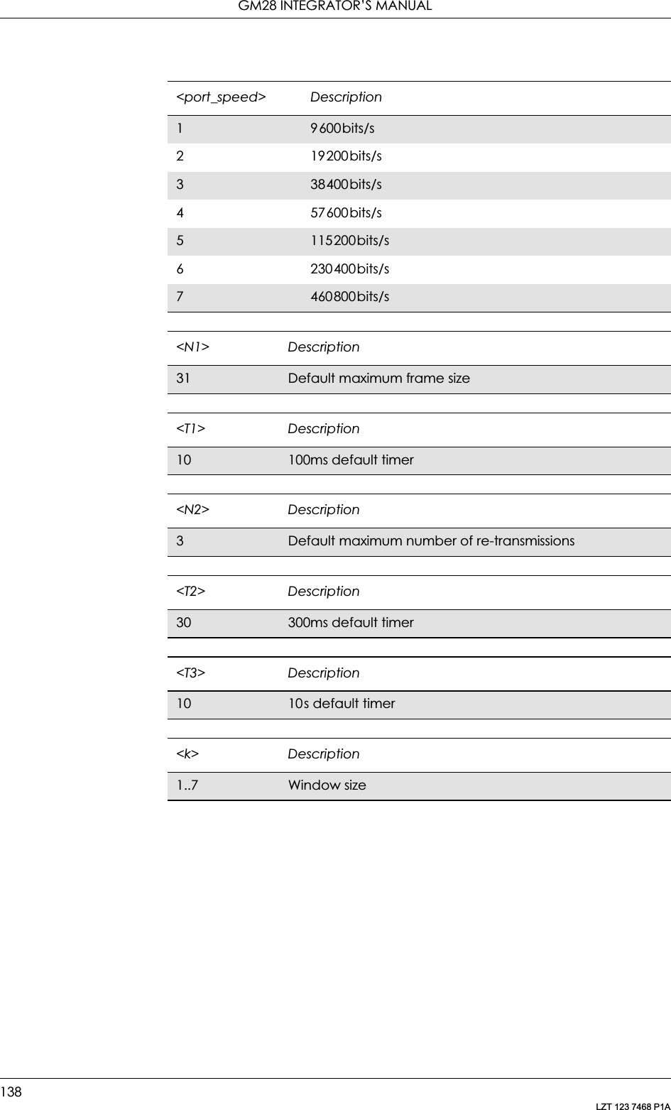
![GM28 INTEGRATOR’S MANUAL142LZT 123 7468 P1AThe specified rate takes effect following the issuance of any result code(s) associated with the current command line.10.15 AT*E2ESC M2M Escape Sequence Guard TimeDefines a guard time for the escape sequence in GPRS to return to on-line command mode i.e. if +++AT<CR> is received either as part of the data stream or a terminating string from the application and no further data is received for the duration of the guard time the modem will go into on line command mode. This guards against the modem accidentally going into on line command mode. The verbose format of +++AT<CR> is <S2><S2><S2>AT<S3>.<rate> DescriptionDiscrete integer valueThe <rate> value specified shall be the rate in bits per second at which the DTE-DCE interface should operate, e.g. “19200” or “115200”. The rates supported by a particular DCE are manufacturer specific.The following rates, are supported;1200240048009600192003840057600115200230400460800Description Command Possible responsesSet GPRS online command guard timeAT*E2ESC=[<gt>] •OK•ERRORRead the current settingAT*E2ESC? *E2ESC: <gt>Show if the command is supportedAT*E2ESC=? •OK•ERROR<gt> Description0No guard time. Default value1-10 Guard time in seconds](https://usermanual.wiki/Sony/6220502-BV.Integrators-User-Manual/User-Guide-324170-Page-142.png)
![11. NETWORK145LZT 123 7468 P1A11.2 AT*E2EMM Ericsson M2M Engineering Monitoring ModeDescription Command Possible ResponsesSet the response presentation modeAT*E2EMM=<n>[,<m>]•ERROR•OKDisplay modeneighbour cells are taken from the toplist*E2EMM:Serving CellMCC,MNC,LAC,CellID,BSIC,Ch[,RxL,C1,C2][,RxLFull,RxLSub,RxQFull,RxQSub,TA,TN],<mcc>,<mnc>,<lac>,<ci>,<bsic>,<ch> [,<rxl>,<c1>,<c2>][,<rxlFull>,<rxlSub>, <rxqfull>,<rxqsub>,<ta>,<tn>],NeighBours CellsMCC,MNC,LAC,CellID,BSIC,Ch,RxL[,C1,C2],<mcc>,<mnc>,<lac>,<ci>,<bsic>,<ch>,<rxl>[,<c1>,<c2>]<mcc>,<mnc>,<lac>,<ci>,<bsic>,<ch>,<rxl>[,<c1>,<c2>]…<mcc>,<mnc>,<lac>,<ci>,<bsic>,<ch>,<rxl>[,<c1>,<c2>]OKCompact mode.The first cell is the serving cell, the rest are neighbour cells taken from the toplist*E2EMM: <mcc>,<mnc>,<ci>, <bsic>,<ch>[,<rxl>][,<rxlSub>,<rxqsub>, <ta>],<mcc>,<mnc>,<ci>,<bsic>,<ch>, <rxl>,<mcc>,<mnc>,<ci>,<bsic>,<ch>,<rxl>,…<mcc>,<mnc>,<ci>,<bsic>,<ch>,<rxl>OKVerbose mode.The first cell is the serving cell and the rest are neighbour cells as provided by the network in the system info. messages (2 and 5) and via the AT*E2NBTS command*E2EMM: <mcc>,<mnc>,<lac>, <ci>,<bsic>,<ch>[,<rxl>,<c1>,<c2>] [,<rxlFull>,<rxlSub>,<rxqfull>,<rxqsub>, <ta>,<tn>],<mcc>,<mnc>,<lac>,<ci>,<bsic>,<ch>,<rxl>[,<c1>,<c2>]<mcc>,<mnc>,<lac>,<ci>,<bsic>,<ch>,<rxl>[,<c1>,<c2>]…<mcc>,<mnc>,<lac>,<ci>,<bsic>,<ch>,<rxl>[,<c1>,<c2>]OKReduced display mode - info. as display mode but without text headings or <CR><LF> separators, neighbour cells from top list*E2EMM: <mcc>,<mnc>,<lac>, <ci>,<bsic>,<ch>[,<rxl>,<c1>,<c2>] [,<rxlFull>,<rxlSub>,<rxqfull>,<rxqsub>, <ta>,<tn>],<mcc>,<mnc>,<lac>,<ci>,<bsic>,<ch>,<rxl>[,<c1>,<c2>]<mcc>,<mnc>,<lac>,<ci>,<bsic>,<ch>,<rxl>[,<c1>,<c2>]…<mcc>,<mnc>,<lac>,<ci>,<bsic>,<ch>,<rxl>[,<c1>,<c2>]OKRead the commandAT*E2EMM? • *E2EMM: <n>•ERRORShow if the command is supportedAT*E2EMM=?• *E2EMM: (list of supported <n>s),(list of supported <m>s)•ERROR](https://usermanual.wiki/Sony/6220502-BV.Integrators-User-Manual/User-Guide-324170-Page-145.png)
![GM28 INTEGRATOR’S MANUAL146LZT 123 7468 P1AThere are four presentation format modes (Display, Compact, Verbose, and Reduced Display) and two response types (one shot response or continuous unsolicited responses).The purpose of the presentation format mode Display is to display the data in a readable form, including headers and line breaks (<CR><LF>). This format is, however, not well suited for machine decoding. The formats Verbose, Compact and Reduced Display do not have headers or line breaks. Verbose mode displays more parameters than the compact mode.The response types give the user the choice of one a shot information or an unsolicited response with <m> seconds between each response.ExamplesAT*E2EMM=1*E2EMM:<CR><LF>Serving Cell<CR><LF>MCC,MNC,LAC,CellID,BSIC,Ch[,RxL,C1,C2][,RxLFull,RxLSub,RxQFull,RxQSub,TA,TN]<CR><LF><mcc>,<mnc>,<lac>,<ci>,<bsic>,<ch>[,<rxl>,<c1>,<c2>][,<rxlFull>,<rxlSub>,<rxqfull>,<rxqsub>,<ta>,<tn>]<CR><LF>NeighBours Cells<CR><LF>MCC,MNC,LAC,CellID,BSIC,Ch,RxL[,C1,C2]<CR><LF><mcc>,<mnc>,<lac>,<ci>,<bsic>,<ch>,<rxl>[,<c1>,<c2>]<CR><LF><mcc>,<mnc>,<lac>,<ci>,<bsic>,<ch>,<rxl>[,<c1>,<c2>]<CR><LF>…<mcc>,<mnc>,<lac>,<ci>,<bsic>,<ch>,<rxl>[,<c1>,<c2>]<CR><LF>OKAT*E2EMM=3*E2EMM: <servcell mcc>,<servcell mnc>,<servcell ci>,<servcell bsic>,<servcell ch>[,<servcell rxl>][,<servcell rxlSub>,<servcell rxqsub>,<servcell ta>],<neighborcell1 mcc>,<neighborcell1 mnc>,<neighborcell1 ci>,<neighborcell1 bsic>,<neighborcell1 ch>,<neighborcell1 rxl>,<neighborcell2 mcc>,<neighborcell2 mnc>,<neighborcell2 ci>,<neighborcell2 bsic>,<neighborcell2 ch>,<neighborcell2 rxl>,…<neighborcelln mcc>,<neighborcellnmnc>,<neighborcellnci>, <neighborcelln bsic>,<neighborcelln ch>,<neighborcelln rxl><CR><LF>OKAT*E2EMM=5*E2EMM: <servcell mcc>,<servcell mnc>,<servcell lac>,<servcell ci>,<servcell bsic>,<servcell ch>[,<servcell rxl>,<servcell C1>,<servcell C2>][,<servcell rxlFull>,<servcell rxlSub>,<servcell rxqfull>,<servcell rxqsub>,<servcell tn>,<servcell ta>],](https://usermanual.wiki/Sony/6220502-BV.Integrators-User-Manual/User-Guide-324170-Page-146.png)
![11. NETWORK147LZT 123 7468 P1A<neighborcell1 mcc>,<neighborcell1 mnc>,<neighborcell1 lac>,<neighborcell1 ci>,<neighborcell1 bsic>,<neighborcell1 ch>,<neighborcell1 rxl>[,<neighborcell1 C1>,<neighborcell1 C2>],<neighborcell2 mcc>,<neighborcell2 mnc>,<neighborcell2 lac>,<neighborcell2 ci>,<neighborcell2 bsic>,<neighborcell2 ch>,<neighborcell2 rxl>[,<neighborcell2 C1>,<neighborcell2 C2>],…<neighborcelln mcc>,<neighborcellnmnc>,<neighborcelln lac>,<neighborcelln ci>,<neighborcelln bsic>,<neighborcelln ch>,<neighborcelln rxl>[,<neighborcelln C1>,<neighborcelln C2>]<CR><LF>OKAT*E2EMM=7*E2EMM:<servcell mcc>,<servcell mnc>,<servcell lac>,<servcell ci>,<servcell bsic>,<servcell ch>[,<servcell rxl>,<servcell c1>,<servcell c2>][,<servcell rxlFull>,<servcell rxlSub>,<servcell rxqfull>,<servcell rxqsub>,<servcell ta>,<servcell tn>],<neighborcell1 mcc>,< neighborcell1 mnc>,<neighborcell1 lac>,<neighborcell1 ci>,<neighborcell1 bsic>,<neighborcell1 ch>,<neighborcell1 rxl>[,< neighborcell1 c1>,<neighborcell1 c2>],<neighborcell2 mcc>,<neighborcell2 mnc>,<neighborcell2 lac>,<neighborcell2 ci>,<neighborcell2 bsic>,<neighborcell2 ch>,<neighborcell2 rxl>[,<neighborcell2 c1>,<neighborcell2c2>]…<neighborcelln mcc>,<neighborcelln mnc>,<neighborcelln lac>,<neighborcelln ci>,<neighborcelln bsic>,<neighborcelln ch>,<neighborcelln rxl>[,<neighborcelln c1>,<neighborcelln c2>]OKThe mode setting <n> in the set command has the combination listed in the table below.When <n>=5, the shot information is the same as in <n>=1, but neighbouring cells, which have to be up to 16. This is the information that comes from the Serving Cell through the BCCH, reporting the BTS that are on the Serving Cell's surroundings.<n> Description0Disable network monitoring unsolicited result code. Default value1 One shot presentation of the network location information. Display mode with headers and <CR><LF> line separators2 Enable network location information unsolicited result code in Display mode (like n=1). There will be continuous unsolicited information responses <m> seconds apart3 One shot presentation of the compact network location information](https://usermanual.wiki/Sony/6220502-BV.Integrators-User-Manual/User-Guide-324170-Page-147.png)
![11. NETWORK153LZT 123 7468 P1A11.6 AT*EPNR Ericsson Read SIM Preferred NetworkThis command is used to read the SIM preferred list of networks (EFPLMNSEL).Description Command Possible ResponsesRead entries in SIM preferred listAT*EPNR=<format> [,<index1>[,<index2]]•*EPNR: <index1>,<oper1>[...]*EPNR: <index2>, <oper2>• +CME ERROR: <err>•OK•ERRORTest if the command is supported and list the possible settingsAT*EPNR=? • *EPNR: (list of supported <index>s), (list of supported <format>s)• +CME ERROR: <err>•OK•ERROR<index1> Descriptioninteger Start index (>0)<index2> Descriptioninteger Stop index (>0)<format> Description2Numeric <oper><oper> Descriptionstring String indicates the code for the operator.E.g. GSM - Sweden - Europolitan: “24008” (3 + 2).PCS: 3 digits for country and 3 digits for network](https://usermanual.wiki/Sony/6220502-BV.Integrators-User-Manual/User-Guide-324170-Page-153.png)
![GM28 INTEGRATOR’S MANUAL154LZT 123 7468 P1A11.7 AT*EPNW Ericsson Write SIM Preferred NetworkThis command is used to edit the SIM preferred list of networks (EFPLMNSEL). The entry field <oper> contains mobile country code (MCC) and mobile network code (MNC).11.8 AT*E2SSN Ericsson M2M SIM Serial NumberThis command requests the SIM serial number held in the ICCid field (address 2FE2) on the SIM and returns all valid characters to the TE. This field is detailed in GSM 11.11 section 10.1.1.Description Command Possible ResponsesWrite/delete entries in SIM preferred listAT*EPNW=[<index>] [,<format>,<oper>]• +CME ERROR: <err>•OK•ERRORTest if the command is supported and list the possible settingsAT*EPNW=? • *EPNW: (list of supported <index>s), (list of supported <format>)s• +CME ERROR: <err>•OK•ERROR<index> DescriptionInteger Index to entry in SIM preferred list. The SIM preferred list contains at least 8 positions according to GSM 11.11<format> Description2Numeric <oper><oper> DescriptionString String indicates the code for the operator.E.g. GSM – Sweden - Europolitan: “24008” (3 + 2).PCS: 3 digits for country and 3 digits for networkDescription Command Possible ResponsesRequest SIM Serial numberAT*E2SSN? *E2ESSN: <SSN>Shows if the command is supportedAT*E2SSN=? • OK•ERROR<SSN> DescriptionString without double quotesSIM serial number](https://usermanual.wiki/Sony/6220502-BV.Integrators-User-Manual/User-Guide-324170-Page-154.png)
![11. NETWORK155LZT 123 7468 P1AEXAMPLESAT*E2SSN?8944110063503224707OKwhere the raw data contained in the ICCid field on the SIM is 984411003605234207F7.Test command:AT*E2SSN=?OK11.9 AT*ESLN Ericsson Set Line NameSets the name tag for a selected line.Description Command Possible ResponsesSets the line name tag in the MSAT*ESLN=<line>[,<name>]• +CME ERROR: <err>•OK•ERRORRead the current settingAT*ESLN? • *ESLN: <line1>,<name1><CR><LF> *ESLN: <line2>,<name2>• +CME ERROR: <err>•OK•ERRORTest if the command is supported and list the possible settingsAT*ESLN=? • *ESLN: (list of supported <line>s),<lname>• +CME ERROR: <err>•OK•ERROR<line> Description0This means that the two lines will use the default name tags, i.e. “L1” and “L2”. Default value1 Line 12Line 2<name> DescriptionString Characters for name tagThis parameter is optional when <line> is set to 0<lname> DescriptionInteger Maximum number of characters to use in <name> string (20)](https://usermanual.wiki/Sony/6220502-BV.Integrators-User-Manual/User-Guide-324170-Page-155.png)
![GM28 INTEGRATOR’S MANUAL156LZT 123 7468 P1A11.10 AT+CIMI Subscriber IdentificationCauses the TA to return <IMSI>, identifying the individual SIM attached to the ME.11.11 AT+CLCK Facility LockThe command is used to lock, unlock or interrogate an ME or a network facility <fac>. A password is normally needed to carry out such actions.Call barring facilities are based on GSM supplementary services (refer to GSM 02.88). The interaction of these, with other commands based on other GSM supplementary services, is described in the GSM standard.Description Command Possible ResponsesRead IMSI AT+CIMI •<IMSI>•+CME ERROR <err>•OK•ERRORShow if the command is supportedAT+CIMI=? • OK•ERROR<IMSI> Descriptionstring without double quotesInternational Mobile Subscriber IdentityDescription Command Possible ResponsesRequest facility lock AT+CLCK=<fac>, <mode>[,<passwd> [,<class>]]• when <mode>=2 and command successful: +CLCK: <status>[,<class1> [<CR><LF>+CLCK: <status>,<class2>[...]]• +CME ERROR <err>•OK•ERRORShow if the command is supportedAT+CLCK=? • +CLCK: (list of supported <fac>s)• +CME ERROR <err>•OK<fac> Description“CS” CNTRL (lock CoNTRoL surface (e.g. phone keyboard))“PS” PH-SIM (lock PHone to SIM card) (ME asks password when other than current SIM card inserted)“SC” SIM (lock SIM card) (SIM asks password in ME power-up and when this lock command issued)“FD” SIM fixed dialling feature. PIN2 is required as a password“P2” SIM PIN2](https://usermanual.wiki/Sony/6220502-BV.Integrators-User-Manual/User-Guide-324170-Page-156.png)
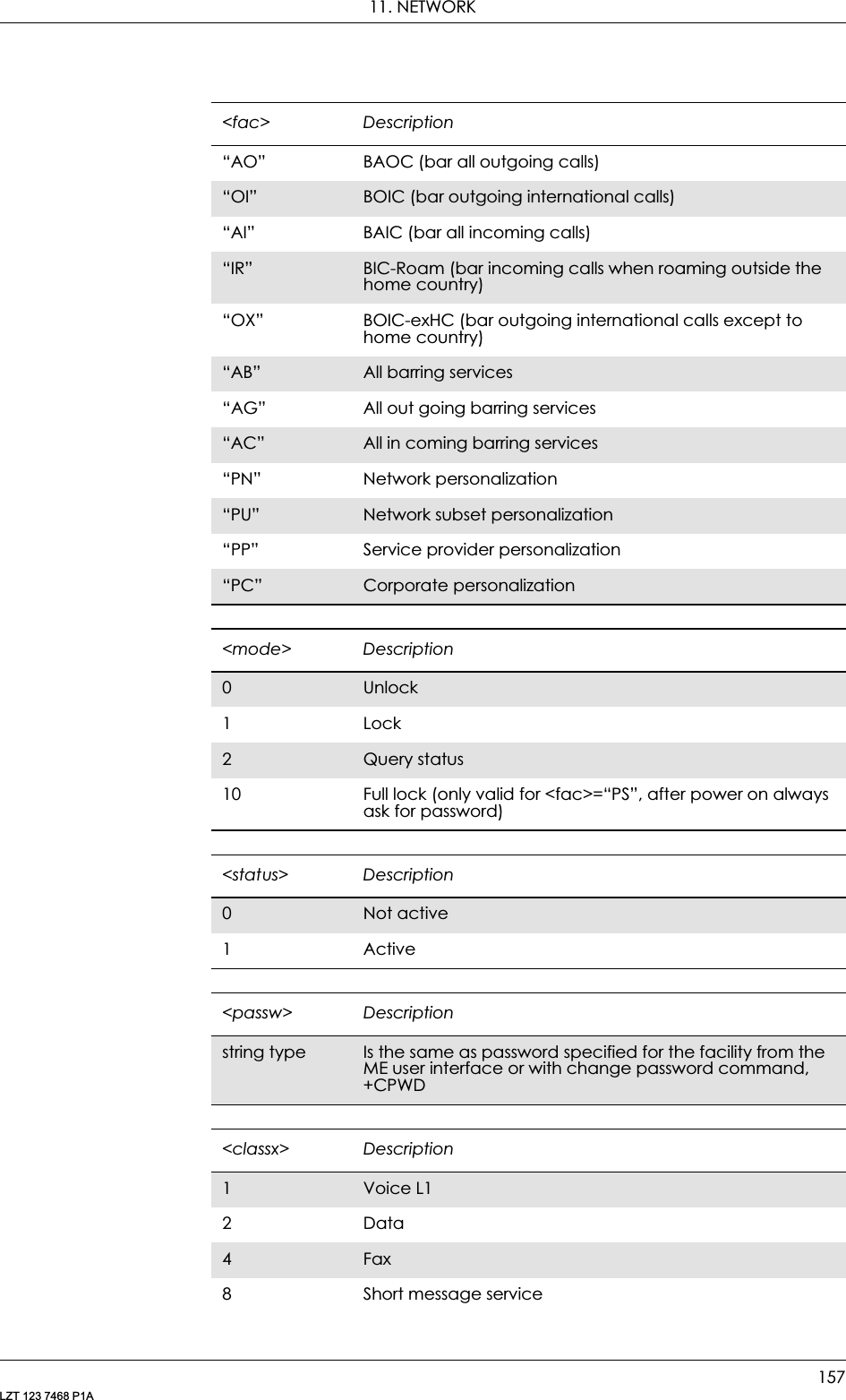
![GM28 INTEGRATOR’S MANUAL158LZT 123 7468 P1A11.12 AT+CNUM Subscriber NumberThis command returns the MSISDNs related to the subscriber (this information can be stored in the SIM or in the ME). If subscriber has different MSISDN for different services, each MSISDN is returned in a separate line.16 Data circuit sync32 Data circuit async64 Dedicated packet access128 Voice L21..30 When “no reply” is enabled or queried, this gives the time in seconds to wait before the call is forwarded. Default value is 20<classx> DescriptionDescription Command Possible ResponsesRequest subscriber numberAT+CNUM •+CNUM: [<alpha1>],<number1>,<type1> [,<speed>,<service>[,<itc>]][<CR><LF>+CNUM: [<alpha2>],<number2>,<type2> [,<speed>,<service> [,<itc>]][…]]• +CME ERROR: <err>•OK•ERRORShow if the command is supportedAT+CNUM=? • +CME ERROR: <err>•OK•ERROR<alphax> DescriptionAlphanumeric stringAssociated with <numberx>; used character set should be the one selected with the Select TE character set command, +CSCS<numberx> DescriptionString type Phone number of format specified by <typex><typex> DescriptionInteger format Type of address, (refer to GSM 04.08 subclause 10.5.4.7)<speed> Descriptiondata rate As defined in subclause 6.7 GSM 07.07](https://usermanual.wiki/Sony/6220502-BV.Integrators-User-Manual/User-Guide-324170-Page-158.png)
![11. NETWORK159LZT 123 7468 P1A11.13 AT+COLP Connected Line Identification PresentationThis command refers to the GSM/UMTS supplementary service COLP (Connected Line Identification Presentation) that enables a calling subscriber to get the connected line identity (COL) of the called party after setting up a mobile originated call. The command enables or disables the presentation of the COL at the TE. It has no effect on the execution of the supplementary service COLR in the network.When enabled (and allowed by the called subscriber), +COLP: <number>,<type>[,<subaddr>,<satype> [,<alpha>]] intermediate result code is returned from the TA to the TE before any +CR or V.25ter responses. It is manufacturer specific if this response is used when normal voice call is established.Read command gives the status of <n>, and also triggers an interrogation of the provision status of the COLP service according 3GPP TS 22.081 (given in <m>).<service> Description0Asynchronous modem4Voice5Fax<itc> Description03.1kHz1 UDIDescription Command Possible ResponsesRequest connected line identification presentationAT+COLP=[<n>] •OK•ERRORShow the current settingAT+COLP? • +COLP: <n>,<m>•OK•ERRORShow if the command is supported AT+COLP=? • +COLP: (list of supported <n>s)•OK•ERROR](https://usermanual.wiki/Sony/6220502-BV.Integrators-User-Manual/User-Guide-324170-Page-159.png)
![GM28 INTEGRATOR’S MANUAL160LZT 123 7468 P1ATest command returns values supported by the TA as a compound value.Intermediate Result codes:+COLP: <number>,<type>[,<subaddr>,<satype> [,<alpha>]]<n> Description0Disable1 Enable<m> Description0COLP not provisioned1 COLP provisioned2unknown (e.g. no network, etc.)](https://usermanual.wiki/Sony/6220502-BV.Integrators-User-Manual/User-Guide-324170-Page-160.png)
![11. NETWORK161LZT 123 7468 P1A11.14 AT+COPS Operator SelectionForces an attempt to select and register the GSM network operator.Description Command Possible ResponsesRequest operator selectionAT+COPS=[<mode> [,<format>[,<oper>]]]• +CME ERROR <err>•OK• ERRORShows the current settingAT+COPS? • +COPS: <mode>[,<format>, <oper>]• +CME ERROR <err>•OK• ERRORShow if the command is supportedAT+COPS=? • +COPS: list of supported (<stat>,long alphanumeric <oper>, short alphanumeric <oper>,numeric <oper>)s• +CME ERROR <err>•OK• ERROR<mode> Description0Automatic (<oper> field is ignored)1 Manual (<oper> field present)3Set only <format> (for read command +COPS?), do not attempt registration/de-registration (<oper> field is ignored); this value is not applicable in read command response4 Manual/automatic (<oper> field present); if manual selection fails, automatic mode (<mode>=0) is entered<format> Description0Automatic (<oper> field is ignored)1 Short format alphanumeric <oper>2Numeric <oper><oper> Descriptionstring type Format determined by the <format> setting](https://usermanual.wiki/Sony/6220502-BV.Integrators-User-Manual/User-Guide-324170-Page-161.png)
![GM28 INTEGRATOR’S MANUAL162LZT 123 7468 P1A11.15 AT+CREG Network RegistrationSet command controls the presentation of an unsolicited result code +CREG: <stat> when <n>=1 and there is a change in the ME network registration status.Read command returns the status of result code presentation and an integer <stat>, which shows whether the network has currently indicated the registration of the ME. Controls the presentation of the unsolicited result code +CREG.<stat> Description0Unknown1 Available2Current3 ForbiddenDescription Command Possible ResponsesRequest network registrationAT+CREG=[<n>] •+CME ERROR <err>•OK•ERRORRead the command AT+CREG? • +CREG: <n>,<stat>•+CME ERROR <err>•OK•ERRORShow if the command is supportedAT+CREG=? • +CREG: (list of supported <n>s)•+CME ERROR <err>•OK•ERROR<n> Description0Disable network registration unsolicited result code. Default value1 Enable network registration unsolicited result code<stat> Description0Not registered, ME is not currently searching for a new operator to register with1 Registered, home network](https://usermanual.wiki/Sony/6220502-BV.Integrators-User-Manual/User-Guide-324170-Page-162.png)
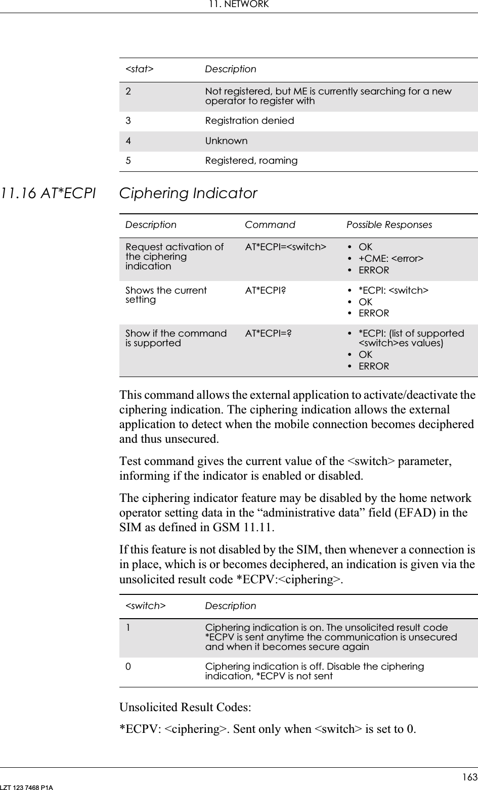
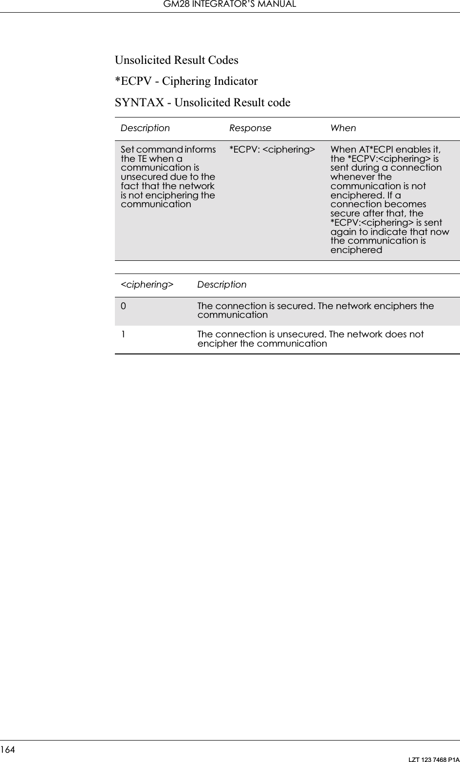
![11. NETWORK165LZT 123 7468 P1A11.17 AT*E2NBTS Ericsson M2M Neighbour BTSThe set command shall provide with the ARFCNs (<ch>) and the BSIC (the BSIC is a cell colour code) to the MS in order to monitor those channels, belonging to the neighbour cells, instead of the ones that come through the air interface, in the serving cell information broadcast channel.It is possible to update that information with up to 16 neighbour cells. If less than 16 <ch>s are provided, then the assigned channels shall substitute the last previous channel (given either by the BCCH or by another AT*E2NBTS command), if it is not in the list yet. Therefore, <ch1>,<bsic1> will substitute BTS 16 in the MS, <ch2>,<bsic2> to the BTS 15 and so on. If any of the <ch>s is already in the top-list, then it is skipped.The read command displays the data of every neighbour cell, including the following parameters: MCC, MNC, Cell ID, BSIC, Channel and Rx Level.Description Command Possible ResponsesSet Neighbour Cells to monitorAT*E2NBTS=<ch1>,<bsic1>[,<ch2>,<bsic2>[,<ch3>,<bsic3>[,<ch4>,<bsic4>[,<ch5>,<bsic5>[,<ch6>,<bsic6>[,<ch7>,<bsic7>[,<ch8>,<bsic8>[,<ch9>,<bsic9>[,<ch10>,<bsic10>[,<ch11>,<bsic11>[,<ch12>,<bsic12>[,<ch13>,<bsic13>[,<ch14>,<bsic14>[,<ch15>,<bsic15>[,<ch16>,<bsic16>]]]]]]]]]]]]]]]•ERROR•OKRead the monitored neighbour cellsAT*E2NBTS? • *E2NBTS: <mcc>,<mnc>,<ci>,<bsic>,<ch>,<rxl><CR><LF><mcc>,<mnc>,<ci>,<bsic>,<ch>,<rxl><CR><LF>…<mcc>,<mnc>,<ci>,<bsic>,<ch>,<rxl><CR><LF><CR><LF>•OK•ERRORShow if the command is supportedAT*E2NBTS=? • *E2NBTS: (list of supported <ch>s)•ERROR<ch> Description(0-1023) It represents the ARFCN that shows the Absolute RF Channel, which identifies a BCCH carrier](https://usermanual.wiki/Sony/6220502-BV.Integrators-User-Manual/User-Guide-324170-Page-165.png)
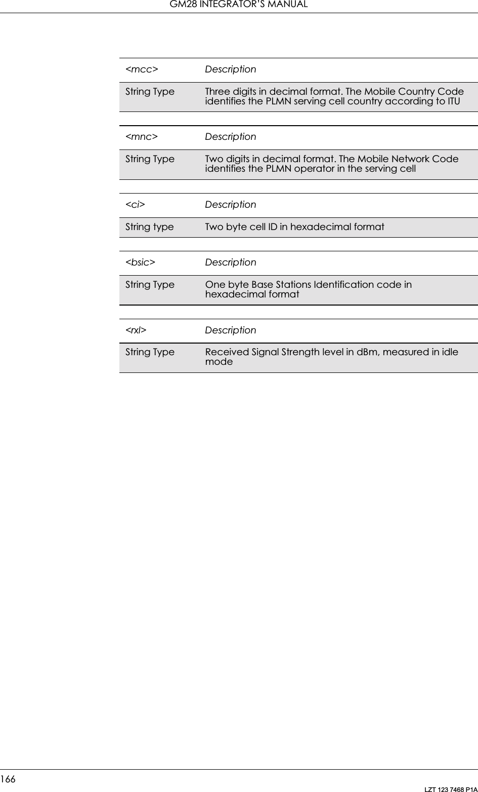
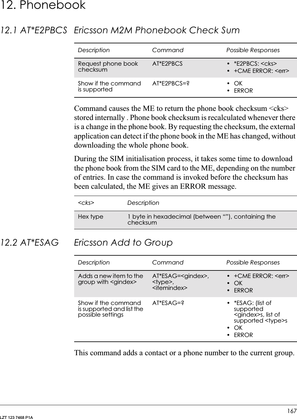
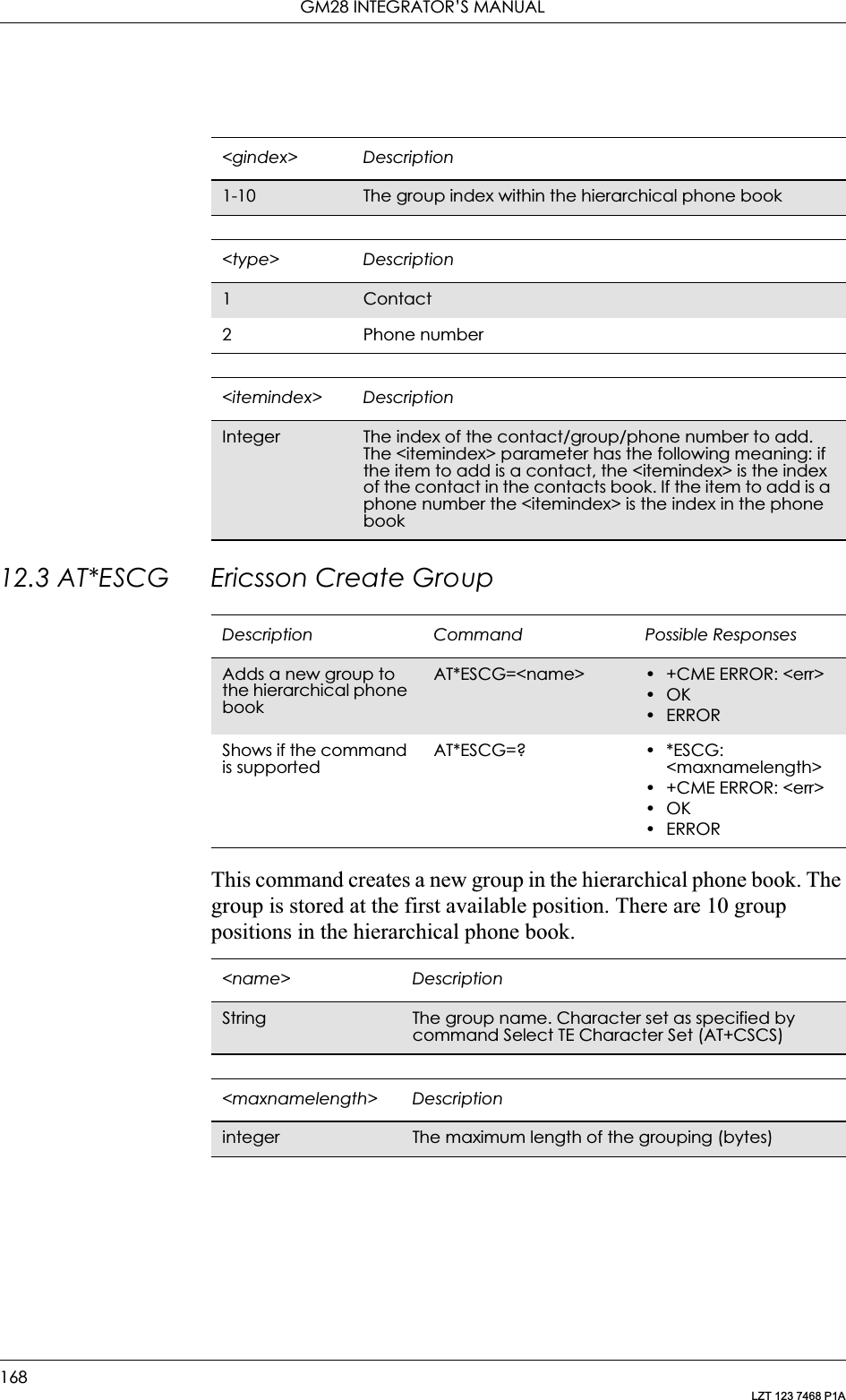
![12. PHONEBOOK169LZT 123 7468 P1A12.4 AT*ESCN Ericsson Set Credit Card NumberCommand is used to:• set up a credit card number in the ME.• disable credit card calls.• enable one of the credit card call services.• query the settings for one of the services.• query the active credit call access server.Description Command Possible ResponsesSet up a credit card numberAT*ESCN=<mode> [,<passwd>][,<indexn>] [,<asn>,<type>,<name>,<vercode>[,<send order>]]• +CME ERROR: <err>when mode=3:*ESCN: <indexn>,<asn>,<type>,<name>,<vercode>,<send order>When mode=4:*ESCN: <selindexn>•OK•ERRORTest if the command is supportedAT*ESCN=? • *ESCN: (list of supported <index>s),(list of supported <mode>s),(list of supported <send order>s)• +CME ERROR: <err>•OK•ERROR<mode> Description0Settings for a credit card call (<passwd>, <indexn>, <asn>,<type>,<name>,<vercode> [,<send order>]). The four (4) parameters (<passwd>, <indexn>, <asn>, <vercode>) are mandatory when <mode>=0. If all those are not submitted ERROR will be returned1 Disable credit card calling (<passwd>). If any other parameters are submitted, they are ignored2Enable one of the credit card call services (<passwd>, <indexn>). If any other parameters are submitted, they are ignored3 Query (<passwd>, <indexn>). If any other parameters are submitted, they are ignored4Query for the selected credit call access server. If any parameters are submitted, they are ignored<passwd> DescriptionString character string, phone lock code “PS”, PH-SIM](https://usermanual.wiki/Sony/6220502-BV.Integrators-User-Manual/User-Guide-324170-Page-169.png)
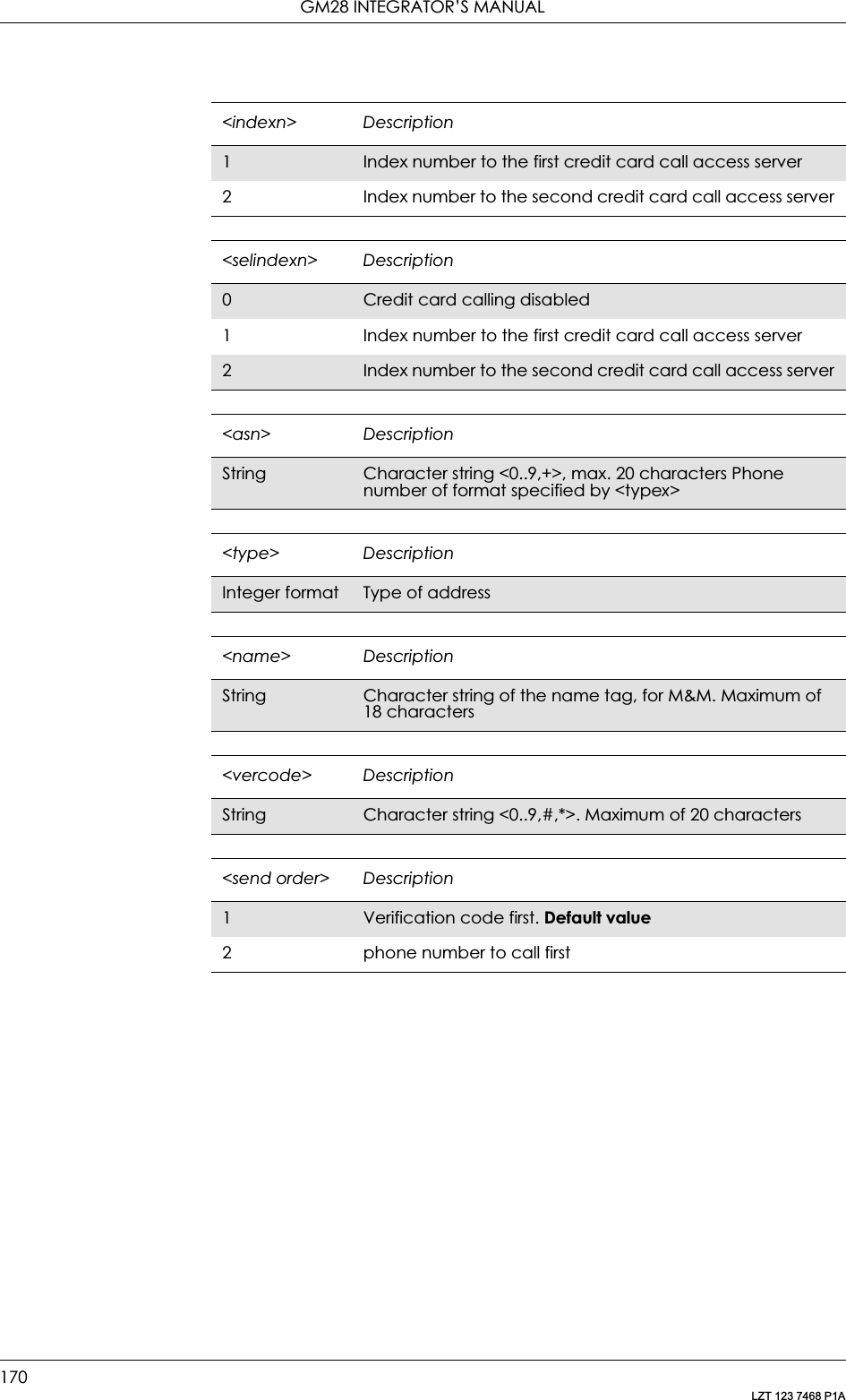
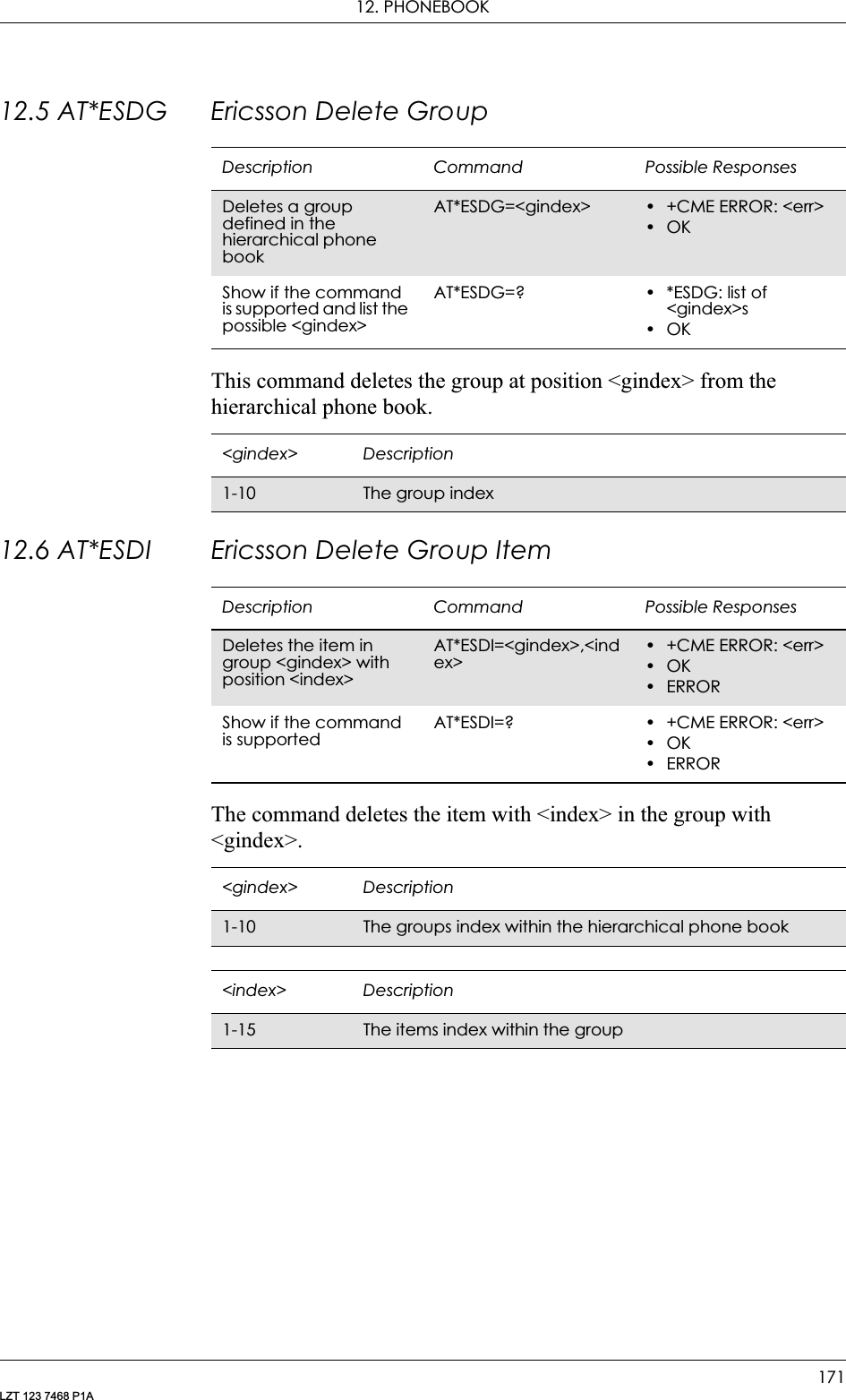
![GM28 INTEGRATOR’S MANUAL172LZT 123 7468 P1A12.7 AT*ESGR Ericsson Group ReadThis command lists the groups in the hierarchical phone book.12.8 AT*EGIR Ericsson Group Item ReadThis command lists the items stored in the group identified by <gindex>.Description Command Possible ResponsesLists the groups defined in the hierarchical phone bookAT*ESGR • *ESGR: <gindex1>, <name1>[<CR><LF> <gindex2>, <name2>..]•OK•ERRORShows if the command is supportedAT*ESGR=? OK<gindex> Description1-10 The group index<name> DescriptionString The group nameDescription Command Possible ResponsesLists the items in the <gindex> groupAT*EGIR=<gindex> • *EGIR: <index1>, <type1>,<itemindex> [<CF><LF><index2>, <type2>, <itemindex>[...]]•OK•ERRORShow if the command is supportedAT*EGIR=? • OK•ERROR<gindex> Description1-10 The groups index within the hierarchical phonebook<index> Description1-15 The items index within the group<type> DescriptionInteger The kind of item. See AT*ESAG <item> table for definition](https://usermanual.wiki/Sony/6220502-BV.Integrators-User-Manual/User-Guide-324170-Page-172.png)
![12. PHONEBOOK173LZT 123 7468 P1A12.9 AT*ESNU Ericsson Settings NumberThis command sets a <type> number, in the format <number type>, in the MS.<itemindex> DescriptionInteger The item's index within the phonebook/contacts/groupDescription Command Possible ResponsesSets a number in the MSAT*ESNU=<type>,<number>[,<number type>]• +CME ERROR: <err>•OK•ERRORTest if the command is supported and show possible settingsAT*ESNU=? • *ESNU: (list of supported <type>s)• +CME ERROR: <err>•OK•ERRORRead the current settingAT*ESNU? • *ESNU: <type 1>,<number 1>,<number type 1><CR><LF> ….*ESNU: <type n>,<number n>,<number type n>• +CME ERROR: <err>•OK•ERROR<type> Description0Voice L11Voice L22Fax3Data<number type> Description129 Default value when dialling string does not include the international access code character ‘+’145 Default value when dialling string includes the international access code character ‘+’<number> Description0-9, + Number](https://usermanual.wiki/Sony/6220502-BV.Integrators-User-Manual/User-Guide-324170-Page-173.png)
![GM28 INTEGRATOR’S MANUAL174LZT 123 7468 P1A12.10 AT+CPBF Phonebook FindReturns phone book entries whose alphanumeric field starts with <findtext>. Only currently selected source will be searched for,12.11 AT+CPBR Phonebook ReadReturns phone book entries in location number range <index1>... <index2> from the current phone book memory storage selected with +CPBS. If <index2> is left out, only location <index1> is returned. Entry fields returned are location number <indexn>, phone number stored there <number> (of format <type>) and text <text> associated with the number.Description Command Possible ResponsesShows the current setting+CPBF=<findtext> •+CPBF: <index1>,<number>,<type>,<text>[[...]<CR><LF>+CBPF: <index2>,<number>,<type>,<text>]• +CME ERROR: <err>•OK• ERRORShow if the command is supported+CPBF=? • +CPBF: <nlength>,<tlength>• +CME ERROR: <err>•OK• ERROR<findtext> Descriptionstring type Field of maximum length <tlength>; character set as specified by the select TE character set command, +CSCSDescription Command Possible ResponsesRead phone book entries+CPBR=<index1>[,<index2>]• +CPBR:<index1>,<number>, <type>,<text>[[,<text_date>, <text_time>]<CR><LF>+CPBR: <index2>,<number>,<type>, <text>[,<text_date>, <text_time>]]• +CME ERROR <err>•OK• ERRORTest if the command is supported+CPBR=? • +CPBR: (list of supported <index>s),<nlength>,<tlength>• +CME ERROR <err>•OK• ERROR<indexn> Descriptioninteger type Values in the range of location numbers of phone book memory](https://usermanual.wiki/Sony/6220502-BV.Integrators-User-Manual/User-Guide-324170-Page-174.png)
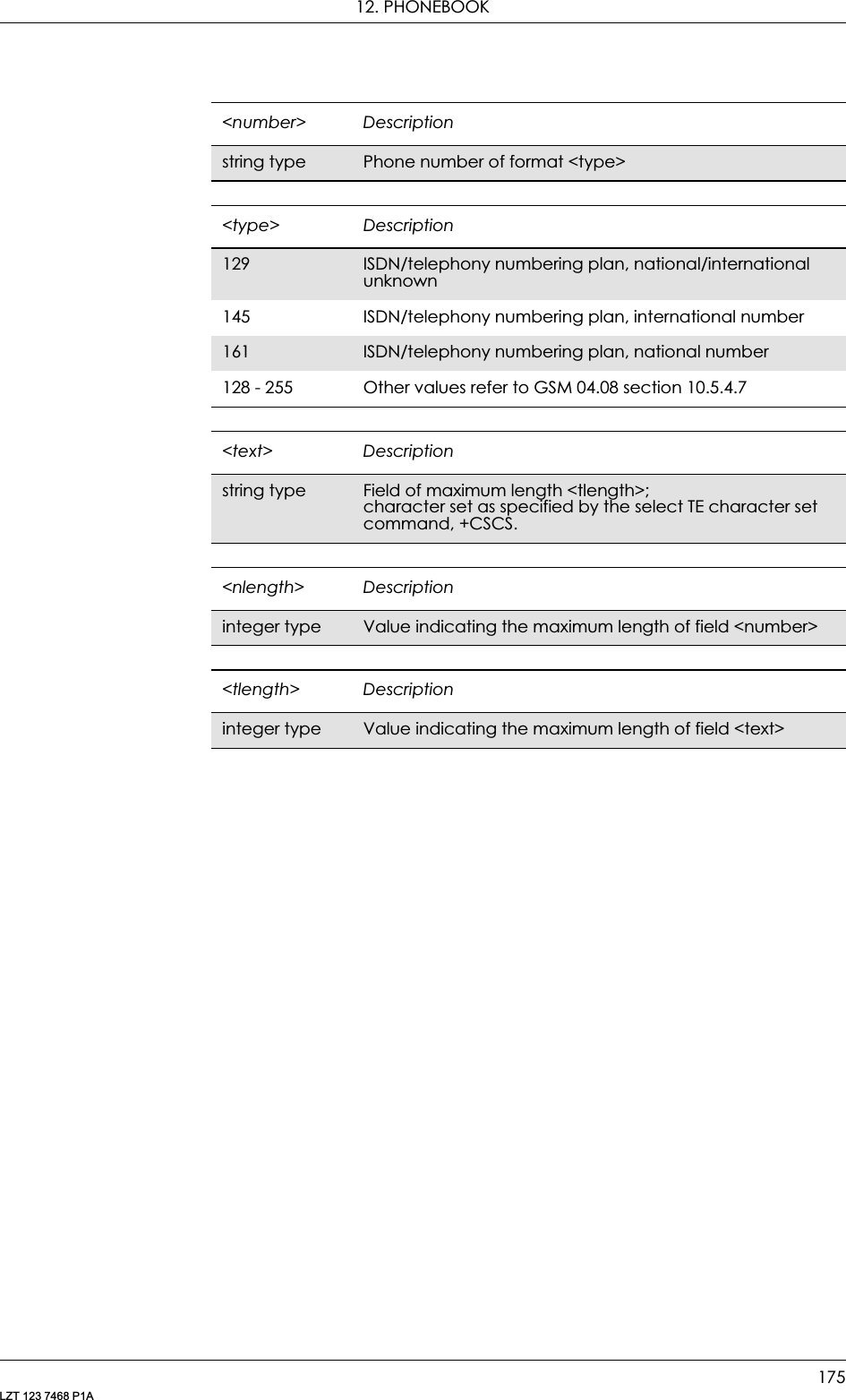
![GM28 INTEGRATOR’S MANUAL176LZT 123 7468 P1A12.12 AT+CPBS Phone StorageSelects phone book memory storage <storage>, which is used by other phone book commands. Read command returns currently selected memory, and when supported by manufacturer, number of used locations and total number of locations in the memory.Description Command Possible ResponsesSet phone book storageAT+CPBS=<storage>[,<password>]•+CME ERROR <err>•OK•ERRORRead the current settingAT+CPBS? • +CPBS: <storage>•+CME ERROR <err>•OK•ERRORTest if the command is supportedAT+CPBS=? • +CPBS: (list of supported <storage>s)•+CME ERROR <err>•OK•ERROR<storage> Description“FD” Fixed dialled numbers“EN” Emergency numbers“ME” ME phone book“SM” SIM phone book“DC” ME dialled calls list (30 entries)“RC” ME received calls list (30 entries)“MC” ME missed calls list (30 entries)<passwd> DescriptionString type Represents the password required when selecting password protected <storage>s, for example PIN2 for storage “ME”](https://usermanual.wiki/Sony/6220502-BV.Integrators-User-Manual/User-Guide-324170-Page-176.png)
![12. PHONEBOOK177LZT 123 7468 P1A12.13 AT+CPBW Phonebook WriteWrites phone book entry in location number <index> in the current phone book memory storage area, selected with AT+CPBS. If the <number> and <text> parameters are omitted, the entry is deleted. If <index> is omitted but <number> is included, the entry is written to the first free location in the phone book.Description Command Possible ResponsesRequest phone book writeAT+CPBW=[<index>][, <number>[,<type>[,<text>]]]• +CME ERROR <err>•OK•ERRORShow if the command is supportedAT+CPBW=? • +CPBW: (list of supported <index>s),<nlength>,(list of supported <type>s),<tlength>• +CME ERROR <err>•OK•ERROR<index> Descriptioninteger type Values in the range of location numbers of phone book memory<number> Descriptionstring type Phone number of format <type><type> Descriptioninteger format Type of address octet, default 145 when dialing string includes international access code character "+", otherwise 129. (refer to GSM 04.08 subclause 10.5.4.7)129 ISDN/telephony numbering plan, national/international unknown145 ISDN/telephony numbering plan, international number161 ISDN/telephony numbering plan, national number128-255 Other values refer GSM 04.08 section 10.5.4.7<text> Descriptionstring type Field of maximum length <tlength>;character set as specified by the select TE character set command, +CSCS<nlength> Descriptioninteger type Value indicating the maximum length of field <number>](https://usermanual.wiki/Sony/6220502-BV.Integrators-User-Manual/User-Guide-324170-Page-177.png)
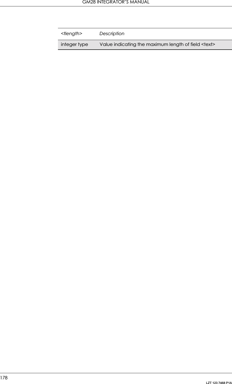
![179LZT 123 7468 P1A13. Short Message Services - Point to Point13.1 AT+CPIN PIN ControlSee 3.23, AT+CPIN PIN Control13.2 AT+CGSMS Select Service for MO SMS MessagesSee 6.10, AT+CGSMS Select Service for MO SMS Messages13.3 AT+CPMS Preferred Message StorageCommon for both PDU (Protocol Data Unit) and Text ModesSelects memory storage <mem1>, <mem2> and <mem3> to be used for reading, writing, etc. If chosen storage is not appropriate for the ME (but is supported by the TA), final result code +CMS ERROR: <err> is returned.Description Command Possible ResponsesSet preferred message storageAT+CPMS=<mem1>[,<mem2>] [,<mem3>]•+CPMS: <used1>,<total1>,<used2>,<total2>,<used3>,<total3>• +CMS ERROR: <err>•OK•ERRORRead the command AT+CPMS? • +CPMS: <mem1>,<used1>,<total1,<mem2>,<used2>,<total2,<mem3>,<used3>,<total3>• +CMS ERROR: <err>•OK•ERRORShow if the command is supportedAT+CPMS=? • +CPMS: (list of supported <mem1>s),(list of supported <mem2>s),(list of supported <mem3>s)•OK•ERROR](https://usermanual.wiki/Sony/6220502-BV.Integrators-User-Manual/User-Guide-324170-Page-179.png)
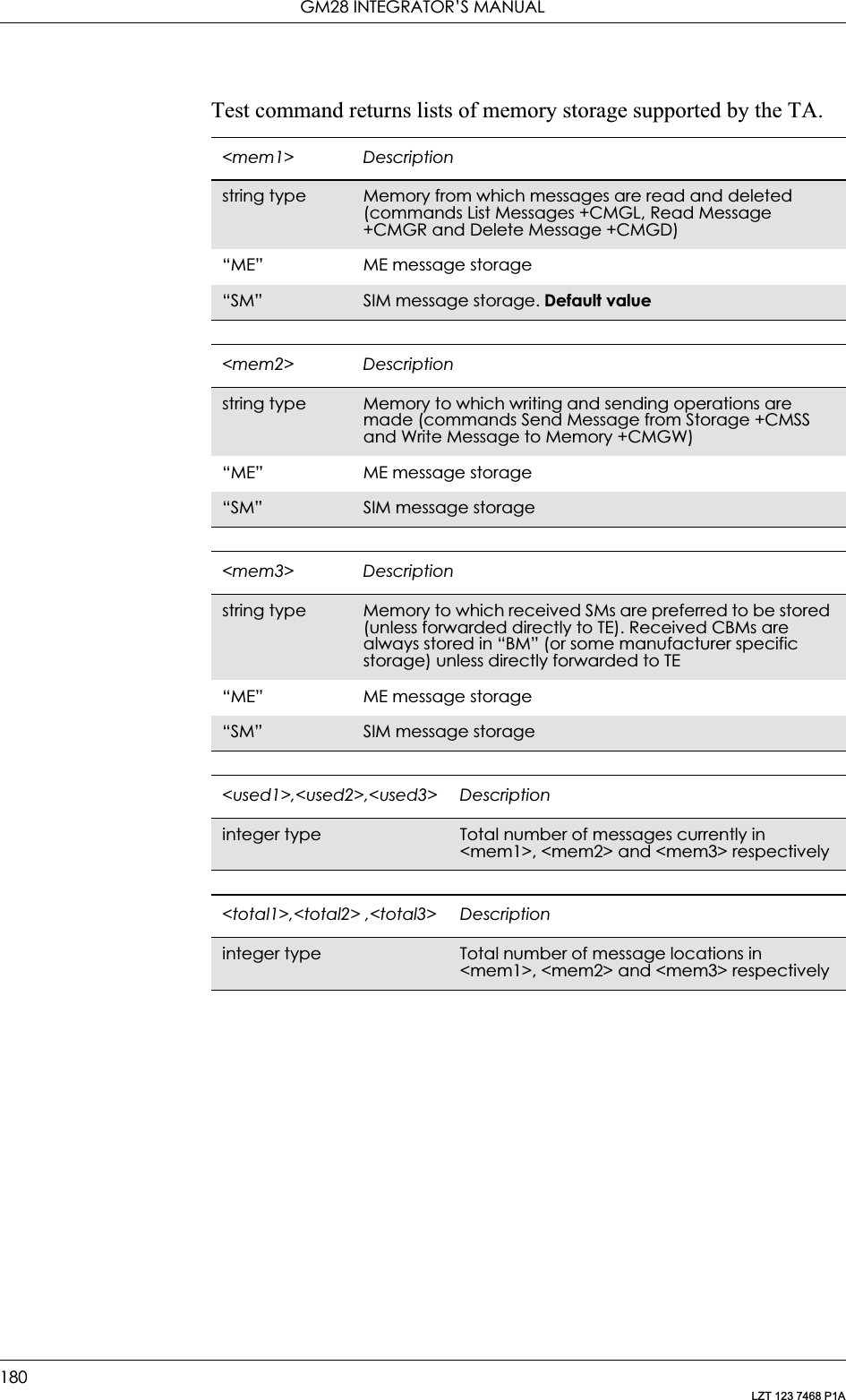
![13. SHORT MESSAGE SERVICES - POINT TO POINT181LZT 123 7468 P1A13.4 AT+CSCA Service Centre AddressCommon for both PDU and Text ModesUpdates the SMSC address, through which mobile originated SMs are transmitted. In text mode, the setting is used by send (+CMGS) and write (+CMGW) commands. In PDU mode, the setting is used by the same commands, but only when the length of the SMSC address coded into <pdu> parameter equals zero. Note that a “+” in front of the number in <sca> has precedence over the <tosca> parameter, so that a number starting with “+” will always be treated as an international number.Description Command Possible ResponsesSet service centre addressAT+CSCA=<sca>[,<tosca>]•OK•ERRORShow the current settingAT+CSCA? • +CSCA: <sca>,<tosca>•OK•ERRORShow if the command is supportedAT+CSCA=? •OK•ERROR<sca> Descriptionstring type GSM 04.11 (3G TS 24.011) RP SC address Address-Value field in string format; BCD numbers (or GSM default alphabet characters) are converted to characters of the currently selected TE character set<tosca> Descriptioninteger type GSM 04.11 (3G TS 24.011) RP SC address type-of-address octet in integer format129 ISDN/telephony numbering plan, national/international unknown145 ISDN/telephony numbering plan, international number161 ISDN/telephony numbering plan, national number128-255 Other values refer GSM 04.08 section 10.5.4.7](https://usermanual.wiki/Sony/6220502-BV.Integrators-User-Manual/User-Guide-324170-Page-181.png)
![GM28 INTEGRATOR’S MANUAL182LZT 123 7468 P1A13.5 AT+CMGF Message FormatCommon for both PDU and Text ModesThis command tells the TA, which input and output format to use for messages. The <mode> parameter indicates the format of messages used with send, list, read and write commands, and unsolicited result codes resulting from received messages. Mode can be either PDU mode (entire TP data units used) or text mode (headers and body of the messages given as separate parameters).Test command returns supported modes as a compound value.13.6 AT+CMGW Write Message to MemoryPDU ModeStores a message to memory storage <mem2>. Memory location <index> of the stored message is returned. By default message status will be set to ‘stored unsent’, but parameter <stat> allows other status values to be given. ME/TA manufacturer may choose to use different default <stat> values for different message types. Entering PDU is the Description Command Possible ResponsesSet message format AT+CMGF=<mode> •OK•ERRORRead the current settingAT+CMGF? • +CMGF: <mode>•OK•ERRORShow if the command is supportedAT+CMGF=? • +CMGF: (list of supported <mode>s)•OK•ERROR<mode> Description0PDU mode1 Text modeDescription Command Possible ResponsesWrite message to memoryAT+CMGW=<length> [,<stat>]<CR>PDU is given<ctrl-Z/ESC>• +CMGW: <index>• +CMS ERROR: <err>•OK•ERRORShow if the command is supportedAT+CMGW=? • OK•ERROR](https://usermanual.wiki/Sony/6220502-BV.Integrators-User-Manual/User-Guide-324170-Page-182.png)
![13. SHORT MESSAGE SERVICES - POINT TO POINT183LZT 123 7468 P1Asame as specified by the send message command, +CMGS. If writing fails, final result code +CMS ERROR: <err> is returned. See “AT+CPMS Preferred Message Storage”, page 179.Text ModeStores message (either SMS-DELIVER or SMS-SUBMIT) to memory storage <mem2>. Memory location <index> of the stored message is returned. By default message status will be set to ‘stored unsent’, but parameter <stat> allows also other status values to be given. The entering of text is done as specified in the send message command, +CMGS. If writing fails, final result code +CMS ERROR: <err> is returned.<stat> Description2Stored unsent message (only applicable to SMs)<index> DescriptionInteger type Value in the range of location numbers supported by the associated memory<length> DescriptionInteger type Value indicating in PDU mode (+CMGF=0), the length of the actual TP data unit in octets (i.e. the RP layer SMSC address octets are not counted in the length)<pdu> Description... In the case of SMS: GSM 04.11 SC address followed by GSM 03.40 TPDU in hexadecimal format: ME/TA converts each octet of TP data unit into two IRA character long hexadecimal number (e.g. octet with integer value 42 is presented to TE as two characters 2A (IRA 50 and 65))In the case of CBS: GSM 03.41 TPDU in hexadecimal formatDescription Command Possible ResponsesWrite message to memoryAT+CMGW [=<oa/da> [,<tooa/toda>[,<stat>]]] <CR>Text is entered <ctrl-Z/ESC>• +CMGW: <index>• +CMS ERROR: <err>•OK•ERRORShow if the command is supported AT+CMGW=? • OK•ERROR](https://usermanual.wiki/Sony/6220502-BV.Integrators-User-Manual/User-Guide-324170-Page-183.png)
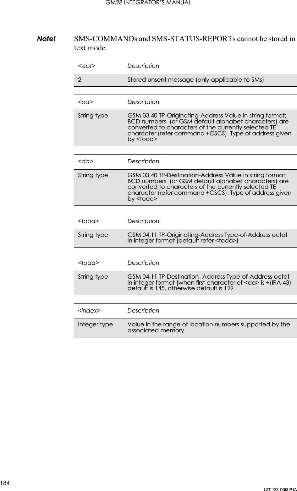
![13. SHORT MESSAGE SERVICES - POINT TO POINT185LZT 123 7468 P1A13.7 AT+CMGS Send MessagePDU ModeSends a message from a TE to the network (SMS-SUBMIT). Message reference value <mr> is returned to the TE on successful message delivery. Optionally, when AT+CSMS <service> value is 1 and there is network support, <ackpdu> is returned. Values can be used to identify message upon unsolicited delivery status report result code. If sending fails in a network or an ME error, final result code +CMS ERROR: <err> is returned. This command is abortable.• <length> must indicate the number of octets coded in the TP layer data unit to be given (i.e. SMSC address octets are excluded).• The TA shall send a four character sequence <CR><LF><greater_than><space> (IRA 13, 10, 62, 32) after command line is terminated with <CR>; after that PDU can be given from TE to ME/TA.• The DCD signal is in the ON state as PDU is given.• The echoing of given characters back from the TA is controlled by V.25ter echo command E.• The PDU shall be hexadecimal format (similarly as specified for <pdu>) and given in one line; ME/TA converts this coding into the actual octets of PDU.• When the length octet of the SMSC address (given in the <pdu>) equals zero, the SMSC address set with command Service Centre Address +CSCA is used.• Sending can be cancelled by giving <ESC> character (IRA 27).• <ctrl-Z> (IRA 26) must be used to indicate the ending of PDU.Description Command Possible ResponsesSend message AT+CMGS=<length> <CR>PDU is given<ctrl-Z/ESC>•+CMGS: <mr>[,<ackpdu>]• +CMS ERROR: <err>•OK•ERRORShow if the command is supportedAT+CMGS=? • OK•ERROR<mr> DescriptionInteger type GSM 03.40 TP-Message-Reference in integer format<length> DescriptionInteger type Value indicating in PDU mode (+CMGF=0), the length of the actual TP data unit in octets (i.e. the RP layer SMSC address octets are not counted in the length)](https://usermanual.wiki/Sony/6220502-BV.Integrators-User-Manual/User-Guide-324170-Page-185.png)
![GM28 INTEGRATOR’S MANUAL186LZT 123 7468 P1AText ModeSends a message from a TE to the network (SMS-SUBMIT). Message reference value <mr> is returned to the TE on successful message delivery. Optionally, when AT+CSMS <service> value is 1 and there is network support, <scts> is returned. Values can be used to identify message upon unsolicited delivery status report result code. If sending fails in a network or an ME error, final result code +CMS ERROR: <err> is returned. This command is abortable.• The entered text (GSM 03.40 TP-Data-Unit) is sent to address <da> and all current settings (refer Set Text Mode Parameters +CSMP and Service Centre Address +CSCA) are used to construct the actual PDU in the ME/TA.• The TA shall send a four character sequence <CR><LF><greater_than><space> (IRA 13, 10, 62, 32) after the command line is terminated with <CR>; after that text can be entered from the TE to the ME/TA.• The DCD signal is in the ON state as text is entered.• The echoing of entered characters back from the TA is controlled by V.25ter echo command E.• The entered text should be formatted as follows:if <dcs> (set with +CSMP) indicates that GSM 03.38 default alphabet is used and <fo> indicates that GSM 03.40 TP-User-Data-Header-Indication is not set:if TE character set other than “HEX” (refer command Select TE Character Set +CSCS in TS 07.07): ME/TA converts the entered text into GSM alphabet according to rules of Annex A; backspace can be used to delete last character and <ackpdu> Description... GSM 03.40 RP-User-Data element of RP-ACK PDU; format is same as for <pdu> in case of SMS, but without GSM 04.11 SC address field and parameter shall be bounded by double quote characters like a normal string type parameterDescription Command Possible ResponsesSend message AT+CMGS=<da> [,<toda>] <CR>Text is entered<ctrl-Z/ESC>•+CMGS: <mr>[,<scts>]• +CMS ERROR: <err>•OK•ERRORShow if the command is supportedAT+CMGS=? • OK•ERROR](https://usermanual.wiki/Sony/6220502-BV.Integrators-User-Manual/User-Guide-324170-Page-186.png)
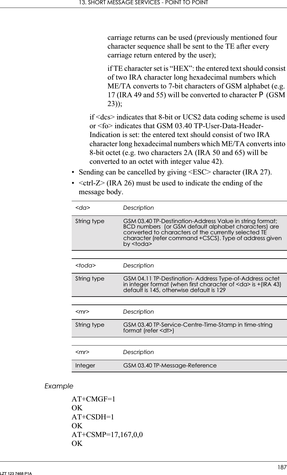
![GM28 INTEGRATOR’S MANUAL188LZT 123 7468 P1AAT+CMGS=“+447747008670”> Test SMS+CMGS: 15OK13.8 AT+CMSS Send From StoragePDU modeSends message with location value <index> from message storage <mem2> to the network (SMS-SUBMIT or SMS-COMMAND). Reference value <mr> is returned to the TE on successful message delivery. If sending fails in a network or an ME error, final result code +CMS ERROR: <err> is returned. This command is abortable. See “AT+CPMS Preferred Message Storage”, page 179.Text ModeSends message with location value <index> from message storage <mem2> to the network (SMS-SUBMIT or SMS-COMMAND). Reference value <mr> is returned to the TE on successful message delivery. Optionally, when +CSMS <service> value is 1 and network Description Command Possible ResponsesSend from storage AT+CMSS=<index> • +CMSS: <mr>• +CMS ERROR: <err>•OK•ERRORShow if the command is supportedAT+CMSS=? • OK•ERROR<index> DescriptionInteger type Value in the range of location numbers supported by the associated memory<mr> DescriptionInteger type GSM 03.40 TP-Message-Reference in integer formatDescription Command Possible ResponsesSend from storage AT+CMSS=<index> [,<da> [,<toda>]]• +CMSS: <mr> [,<scts>]•+CMS ERROR: <err>•OK•ERRORShow if the command is supportedAT+CMSS=? • OK•ERROR](https://usermanual.wiki/Sony/6220502-BV.Integrators-User-Manual/User-Guide-324170-Page-188.png)
![13. SHORT MESSAGE SERVICES - POINT TO POINT189LZT 123 7468 P1Asupports, <scts> is returned. If sending fails in a network or an ME error, final result code +CMS ERROR: <err> is returned. This command is abortable.13.9 AT+CMGC Send CommandPDU ModeSends a command message from a TE to the network (SMS-COMMAND). The entering of PDU is as specified in the send message command, +CMGS. Message reference value <mr> is returned to the <index> DescriptionInteger type Value in the range of location numbers supported by the associated memory<da> DescriptionString type GSM 03.40 TP-Destination-Address Value in string format; BCD numbers (or GSM default alphabet characters) are converted to characters of the currently selected TE character (refer command +CSCS). Type of address given by <toda><toda> DescriptionString type GSM 04.11 TP-Destination- Address Type-of-Address octet in integer format (when first character of <da> is +(IRA 43) default is 145, otherwise default is 129<scts> DescriptionString type GSM 03.40 TP-Service-Centre-Time-Stamp in time-string format (refer <dt>)<mr> DescriptionInteger type GSM 03.40 TP-Message-Reference in integer formatDescription Command Possible ResponsesSend command messageAT+CMGC=<length><CR><pdu><ctrl-Z/ESC>• if PDU mode (+CMGF=0) and sending successful:+CMGC: <mr>[,<ackpdu>]• if sending fails:+CMS ERROR: <err>•OK•ERRORShow if the command is supportedAT+CMGC=? • OK•ERROR](https://usermanual.wiki/Sony/6220502-BV.Integrators-User-Manual/User-Guide-324170-Page-189.png)
![GM28 INTEGRATOR’S MANUAL190LZT 123 7468 P1ATE on successful message delivery. Optionally (when +CSMS <service> value is 1 and network supports) <ackpdu> is returned. Values can be used to identify message upon unsolicited delivery status report result code. If sending fails in a network or an ME error, final result code +CMS ERROR: <err> is returned. This command is abortable.Text ModeSends a command message from a TE to the network (SMS-COMMAND). The entering of text is as specified in the send message command, +CMGS, but the format is fixed to be a sequence of two IRA character long hexadecimal numbers, which the ME/TA converts into <length> DescriptionInteger type Value indicating in PDU mode (+CMGF=0), the length of the actual TP data unit in octets (i.e. the RP layer SMSC address octets are not counted in the length)<pdu> DescriptionString In the case of SMS: GSM 04.11 SC address followed by GSM 03.40 TPDU in hexadecimal format: ME/TA converts each octet of TP data unit into two IRA character long hexadecimal number (e.g. octet with integer value 42 is presented to TE as two characters 2A (IRA 50 and 65))In the case of CBS: GSM 03.41 TPDU in hexadecimal format<mr> DescriptionInteger type GSM 03.40 TP-Message-Reference in integer format<ackpdu> DescriptionString GSM 03.40 RP-User-Data element of RP-ACK PDU; format is same as for <pdu> in case of SMS, but without GSM 04.11 SC address field and parameter shall be bounded by double quote characters like a normal string type parameterDescription Command Possible ResponsesSend command messageAT+CMGC=<fo>,<ct>[,<pid>[,<mn>[,<da>[,<toda>]]]] <CR>Text is entered<ctrl-Z/ESC>• if PDU mode (+CMGF=1) and sending successful:+CMGC: <mr>[,<scts>]• if sending fails:+CMS ERROR: <err>•OK•ERRORShow if the commands is supportedAT+CMGC=? • OK•ERROR](https://usermanual.wiki/Sony/6220502-BV.Integrators-User-Manual/User-Guide-324170-Page-190.png)
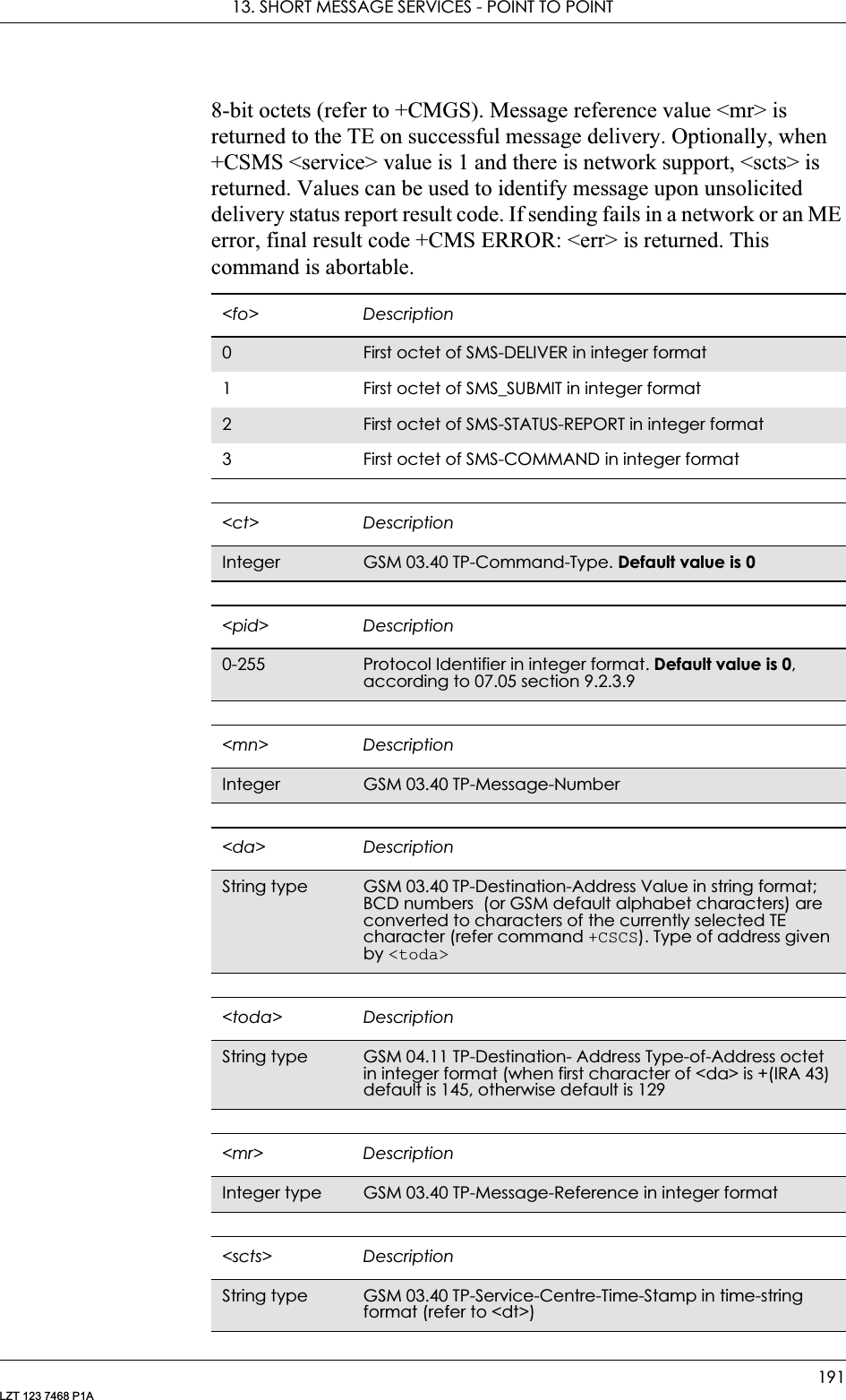
![GM28 INTEGRATOR’S MANUAL192LZT 123 7468 P1A13.10 AT+CNMI New Message Indications to TEPDU ModeSelects the procedure for the way in which new messages received from the network, are indicated to the TE when it is active, e.g. DTR signal is ON. If the TE is inactive (DTR signal is OFF), message receiving is carried out as specified in GSM 03.38 (3G TS 23.038).If the command fails and the error is related to mobile equipment or network, the final result code CMS ERROR: <err> is returned.Description Command Possible ResponsesSet new message indication to TEAT+CNMI=[<mode> [,<mt>[,<bm>[,<ds>]]]]• +CMS ERROR: <err>•OK• ERRORShows the current setting AT+CNMI? • +CNMI: <mode>,<mt>,<bm>,<ds>•OK• ERRORShow if the command is supported AT+CNMI=? •+CNMI: (list of supported <mode>s),(list of supported <mt>s),(list of supported <bm>s),(list of supported <ds>s)•OK• ERROR<mode> Description3Forward unsolicited result codes directly to the TE. TA-TE link specific inband technique used to embed result codes and data when TA is in on-line data mode](https://usermanual.wiki/Sony/6220502-BV.Integrators-User-Manual/User-Guide-324170-Page-192.png)
![13. SHORT MESSAGE SERVICES - POINT TO POINT193LZT 123 7468 P1AUnsolicited Result codes:+CMT: <length><CR><LF><pdu>+CMTI: <mem>,<index>+CBM: <length><CR><LF><pdu>+CDS: <length><CR><LF><pdu>+CDSI: <mem><index><mt> Description0No SMS-DELIVER indications are routed to the TE.No class, Class 0, class 1 and class 3 use <mem3> as preferred storage. Class 2 messages shall be stored in the SIM. If it this is not possible then the MS shall send an error message accordingly to GSM 03.381 SMS-DELIVER is stored into ME/TA and the indication of the memory location is routed to the TE using unsolicited result code:+CMTI: <mem>,<index>2Class 0, class 1, and class 3 SMS-DELIVERs are routed directly to the TE using the unsolicited result code but not stored in ME/TA:+CMT:[<alpha >], <length><CR><LF><pdu> (PDU mode enabled)Class 2 data coding scheme result in indication as defined in <mt>=13 Class 3 SMS-DELIVERs are routed directly to TE using unsolicited result codes +CMT: <length><CR><LF><pdu>. Class 3 SMS-DELIVER is not stored in ME/TA. Messages of other data coding schemes result in indication as defined in <mt>=1<bm> Description0Store message to “BM” (or some manufacturer specific memory). No CBM indications are routed to the TE2 New CBMs are routed directly to the TE using unsolicited result code:+CBM: <length><CR><LF><pdu> (PDU mode enabled). New CBMs are not stored in CBM memory<ds> Description0No SMS-STATUS-REPORTs are routed to the TE. SMS-STATUS-REPORT is stored in ME/TA1 SMS-STATUS-REPORTs are routed to the TE using unsolicited result code: +CDS: < length>< CR>< LF>< pdu> (PDU mode enabled). SMS-STATUS-REPORT is not stored in ME/TA2SMS-STATUS-REPORTs are routed to the TE using unsolicited result code: +CDSI: < mem><index> (PDU mode enabled). SMS-STATUS-REPORT is stored in ME/TA](https://usermanual.wiki/Sony/6220502-BV.Integrators-User-Manual/User-Guide-324170-Page-193.png)
![GM28 INTEGRATOR’S MANUAL194LZT 123 7468 P1AText ModeSelects the procedure for the way in which new messages received from the network, are indicated to the TE when it is active, e.g. DTR signal is ON. If TE is inactive (DTR signal is OFF), message receiving is carried out as specified in GSM 03.38 (3G TS 23.038).If the command fails and the error is related to mobile equipment or network, the final result code CMS ERROR: <err> is returned.Description Command Possible ResponsesSet new message indication to TEAT+CNMI=[<mode> [,<mt>[,<bm>[,<ds>]]]]• +CMS ERROR: <err>•OK• ERRORShows the current settingAT+CNMI? • +CNMI: <mode>,<mt>,<bm>,<ds>•OK• ERRORShow if the command is supportedAT+CNMI=? •+CNMI: (list of supported <mode>s),(list of supported <mt>s),(list of supported <bm>s),(list of supported <ds>s)•OK• ERROR<mode> Description3Forward unsolicited result codes directly to the TE. TA-TE link specific inband technique used to embed result codes and data when TA is in on-line data mode<mt> Description0No SMS-DELIVER indications are routed to the TE.No class, Class 0, class 1 and class 3 use <mem3> as preferred storage. Class 2 messages shall be stored in the SIM. If it this is not possible then the MS shall send an error message accordingly to GSM 03.381 SMS-DELIVER is stored into ME/TA and the indication of the memory location is routed to the TE using unsolicited result code:+CMTI: <mem>,<index>2Class 0, class 1, and class 3 SMS-DELIVERs are routed directly to the TE using the unsolicited result code:+CMT:<oa>, [<alpha>, <scts> [ ,<tooa>,<fo>,<pid>,<dcs>, <sca>,<tosca>,<length>]<CR><LF><data> (text mode enabled). About parameters in italics, refer to the show text mode command, +CSDH3 Class 3 SMS-DELIVERs are routed directly to TE using unsolicited result codes +CMT:<oa>, [<alpha>, <scts> [ ,<tooa>,<fo>,<pid>,<dcs>,<sca>,<tosca>,<length>]<CR><LF><data> (Text Mode enabled). About parameters in italics, refer to the show text mode command, +CSDH. Messages of other data coding schemes result in indication as defined in <mt>=1](https://usermanual.wiki/Sony/6220502-BV.Integrators-User-Manual/User-Guide-324170-Page-194.png)
![13. SHORT MESSAGE SERVICES - POINT TO POINT195LZT 123 7468 P1AUnsolicited Result codes:+CMT:<oa>, [<alpha>, <scts>[,<tooa>,<fo>,<pid>,<dcs>,<sca>,<tosca>,<length>]<CR><LF><data> (Text Mode enabled). Refer to the show text mode command, +CSDH for information on the parameters in italics.+CMTI: <mem>,<index>+CBM: <sn>,<mid>,<dcs>,<page>,<pages><CR><LF><data>+CDS: <fo>,<mr>,[<ra>],[<tora>],<scts>,<dt>,<st>+CDSI: <mem><index>ExampleDisplay cell broadcast messages:AT+CNMI=3,0,2,0,0<bm> Description0Store message to “BM” (or some manufacturer specific memory). No CBM indications are routed to the TE2 New CBMs are routed directly to the TE using unsolicited result code:+CBM: <sn>,<mid>,<dcs>,<page>,<pages><CR><LF><data> (Text mode enabled)<ds> Description0No SMS-STATUS-REPORTs are routed to the TE1 SMS-STATUS-REPORTs are routed to the TE using unsolicited result code: : +CDS: <fo>,<mr>,[<ra>],[<tora>],<scts>,<dt>,<st> (Text mode enabled). SMS-STATUS-REPORT is not stored in ME/TA2SMS-STATUS-REPORTs are routed to the TE using unsolicited result code: +CDSI: < mem><index> (Text mode enabled). SMS-STATUS-REPORT is stored in ME/TA](https://usermanual.wiki/Sony/6220502-BV.Integrators-User-Manual/User-Guide-324170-Page-195.png)
![GM28 INTEGRATOR’S MANUAL196LZT 123 7468 P1A13.11 AT+CMGR Read MessagePDU ModeReturns message with location value <index> from preferred message storage <mem1> to the TE. Status of the message and entire message data unit <pdu> is returned. If status of the message is ‘received unread’, status in the storage changes to ‘received read’. If reading fails, final result code +CMS ERROR: <err> is returned.Description Command Possible ResponsesRead messageAT+CMGR= <index>•+CMGR: <stat>,[<alpha>],<length>] <CR><LF><pdu>• +CMS ERROR: <err>•OK• ERRORShow if the command is supportedAT+CMGR=? • OK• ERROR<stat> Description0Received unread message (i.e. new message)1 Received read message2Stored unsent message (only applicable to SMs)3 Stored sent message (only applicable to SMs)<index> DescriptionInteger type Value in the range of location numbers supported by the associated memory<alpha> DescriptionString type Manufacturing specific. Should be left empty but not omitted<length> DescriptionInteger type Value indicating in PDU mode (+CMGF=0), the length of the actual TP data unit in octets (i.e. the RP layer SMSC address octets are not counted in the length)<pdu> DescriptionIn the case of SMS: GSM 04.11 SC address followed by GSM 03.40 TPDU in hexadecimal format: ME/TA converts each octet of TP data unit into two IRA character long hexadecimal number (e.g. octet with integer value 42 is presented to TE as two characters 2A (IRA 50 and 65))In the case of CBS: GSM 03.41 TPDU in hexadecimal format](https://usermanual.wiki/Sony/6220502-BV.Integrators-User-Manual/User-Guide-324170-Page-196.png)
![13. SHORT MESSAGE SERVICES - POINT TO POINT197LZT 123 7468 P1AText ModeReturns messages with location index <index> from message storage <mem1> to the TE. About text mode parameters in Italics, refer command Show Text Mode Parameters (+CSDH), If the status of the message is ‘received unread’, status in the storage changes to ‘received read’. If listing fails final result code +CMS ERROR: <err> is returned.Description Command Possible ResponsesRead messageAT+CMGR= [<index>]• if text mode (+CMGF=1), command successful and SMS-DELIVER:+CMGR: <stat>,<oa>,[<alpha>],<scts>,[<tooa>,<fo>,<pid>,<dcs>,<sca>,<tosca>, <length>]<CR><LF><data>• if text mode (+CMGF=1), command successful and SMS-SUBMIT:+CMGR: <stat>,<da>,[<alpha>],[<toda>,<fo>, <pid>,<dcs>,[<vp>],<sca>,<tosca>, <length>]<CR><LF><data>• if text mode (+CMGF=1), command successful and SMS-STATUS-REPORT:+CMGR: <stat>,<fo>,<mr>,[<ra>],[<tora>],<scts>,<dt>,<st>• if text mode (+CMGF=1), command successful and SMS-COMMAND:+CMGR: <stat>,<fo>,<ct>[,<pid>,[<mn>],[<da>],[<toda>],<length><CR><LF><cdata>]• if text mode (+CMGF=1), command successful and CBM storage:+CMGR: <stat>,<sn>,<mid>,<dcs>,<page>, <pages><CR><LF><data>• +CMS ERROR: <err>•OK•ERRORShow if the command is supportedAT+CMGR=? • OK•ERROR<index> DescriptionInteger type Value in the range of location numbers supported by <mem1><stat> Description0Received unread message (new message)1 Received read message2Stored unsent message (only applicable to SMs)3 Stored sent message (only applicable to SMs)](https://usermanual.wiki/Sony/6220502-BV.Integrators-User-Manual/User-Guide-324170-Page-197.png)
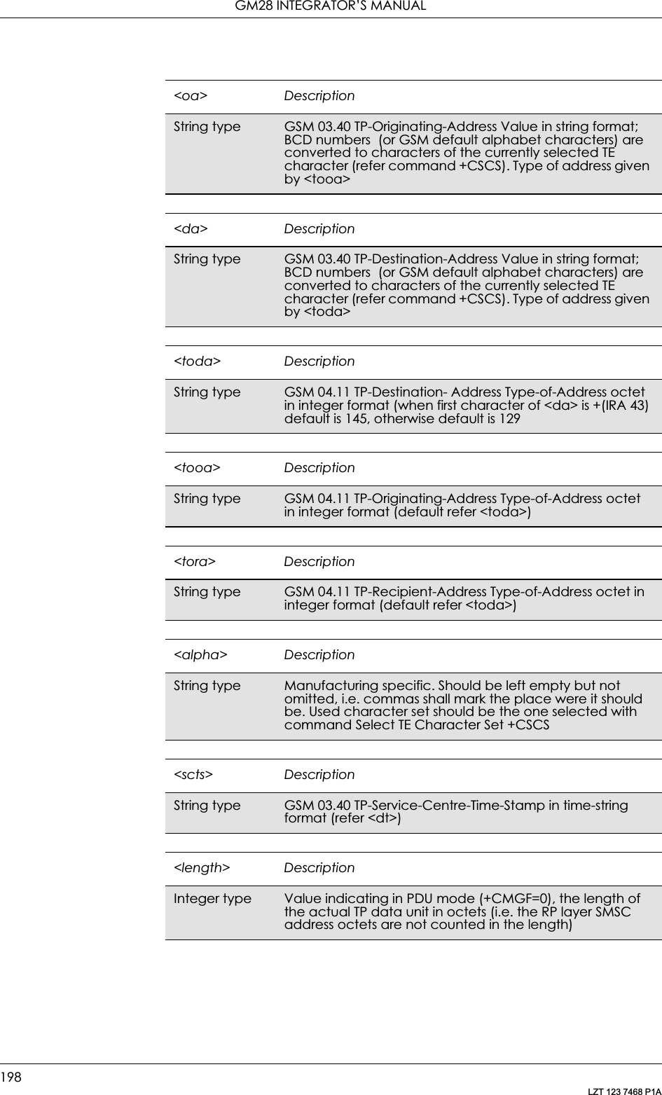
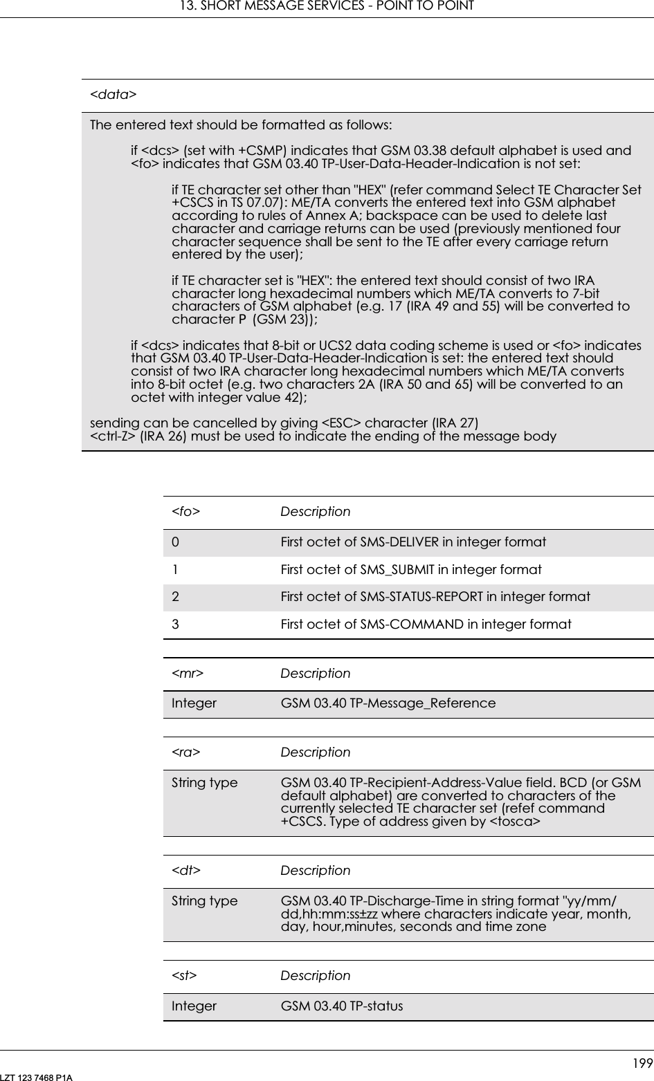
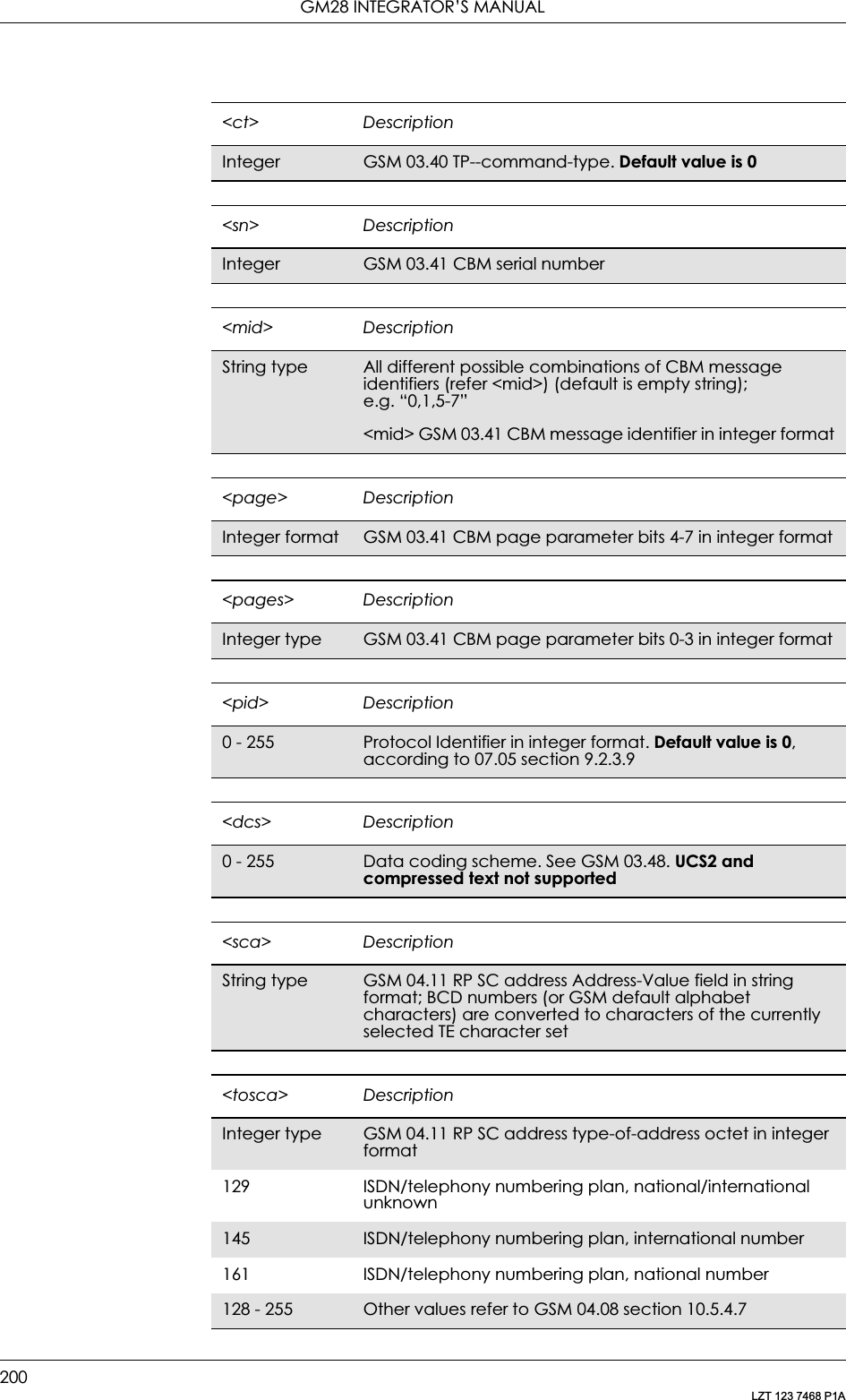
![13. SHORT MESSAGE SERVICES - POINT TO POINT201LZT 123 7468 P1A13.12 AT+CMGL List MessagePDU ModeNote! Returns messages with status value <stat> from preferred message storage <mem1> to the TE. Entire data units <pdu> are returned. If status of the message is ‘received unread’, status in the storage changes to ‘received read’. If listing fails, final result code +CMS ERROR: <err> is returned.<vp> Description0 - 143 (TP-VP+1) x 5 minutes (i.e. 5 minute intervals up to 12 hous)144 - 167 12 hours + ((TP_VP-143) x 30 minutes)168 - 196 (TP-VP-166) x 1 day197 - 255 (TP-VP-192) x 1 week<mn> DescriptionInteger type GSM 03.40 TP-message-numberDescription Command Possible ResponsesList message AT+CMGL [=<stat>] •+CMGL: <index>,<stat>,[<alpha>],<length><CR><LF><pdu>[<CR><LF>+CMGL:<index>,<stat>,[<alpha>],<length><CR><LF><pdu>[…]]• +CMS ERROR: <err>Show if the command is supported AT+CMGL=? • +CMGL: (list of supported <stat>s)<stat> Description0Received unread message (i.e. new message)1 Received read message2Stored unsent message (only applicable to SMs)3 Stored sent message (only applicable to SMs)4All messages (only applicable to +CMGL command)<index> DescriptionInteger type Value in the range of location numbers supported by the associated memory](https://usermanual.wiki/Sony/6220502-BV.Integrators-User-Manual/User-Guide-324170-Page-201.png)
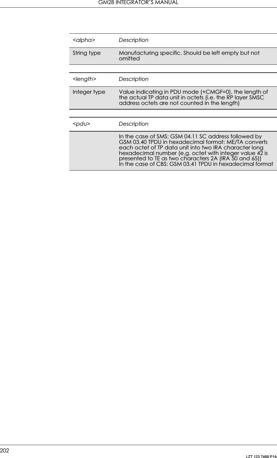
![13. SHORT MESSAGE SERVICES - POINT TO POINT203LZT 123 7468 P1AText ModeReturns messages with status value <stat> from message storage <mem1> to the TE. About text mode parameters in Italics, refer command Show Text Mode Parameters (+CSDH). If the status, of the message is ‘received unread’, status in the storage changes to ‘received read’. If listing fails final result code +CMS ERROR: <err> is returned.Description Command Possible ResponsesList message AT+CMGL =[<stat>]• If text mode (+CMGF=1), command successful and SMS-SUBMITs and SMS-DELIVERs:+CMGL:<index1>,<stat>,<oa/da>,[<alpha>],[<scts>][,<tooa/toda>,<length>]<CR><LF><data>[<CR><LF>+CMGL:<index2>,<stat>,<oa/da>,[<alpha>],[<scts>][,<tooa/toda>,<length>]<CR><LF><data>[…]]• If text mode (+CMGF=1), command successful and SMS-STATUS-REPORT:+CMGL:<index1>,<stat>,<fo>,<mr>, [<ra>],[<tora>],<scts>,<dt>,<st> [<CR><LF>+CMGL:<index2>,<stat>,<fo>,<mr>,[<ra>],[<tora>],<scts>,<dt>,<st>[…]]•If text mode (+CMGF=1), command successful and SMS-COMMANDs:+CMGL:<index>,<stat>,<fo>,<ct> [<CR><LF>+CMGL:<index>,<stat>,<fo>,<ct>[…]]• If text mode (+CMGF=1), command successful and CBM storage:+CMGL:<index>,<stat>,<sn>,<mid>,<page>,<pages>,<CR><LF><data>[<CR><LF>+CMGL:<index>,<stat>,<sn>,<mid>,<page>,<pages><CR><LF> <data>[…]]• Otherwise:+CMS ERROR: <err>Read the current setting•+CMGL:<stat>• +CMS ERROR: <err>Test if the command is supported AT+CMGL=? • +CMGL: (list of supported <stat>s)• +CMS ERROR: <err><index> DescriptionInteger type Value in the range of location numbers supported by <mem1>](https://usermanual.wiki/Sony/6220502-BV.Integrators-User-Manual/User-Guide-324170-Page-203.png)
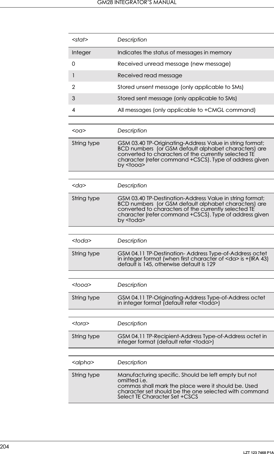
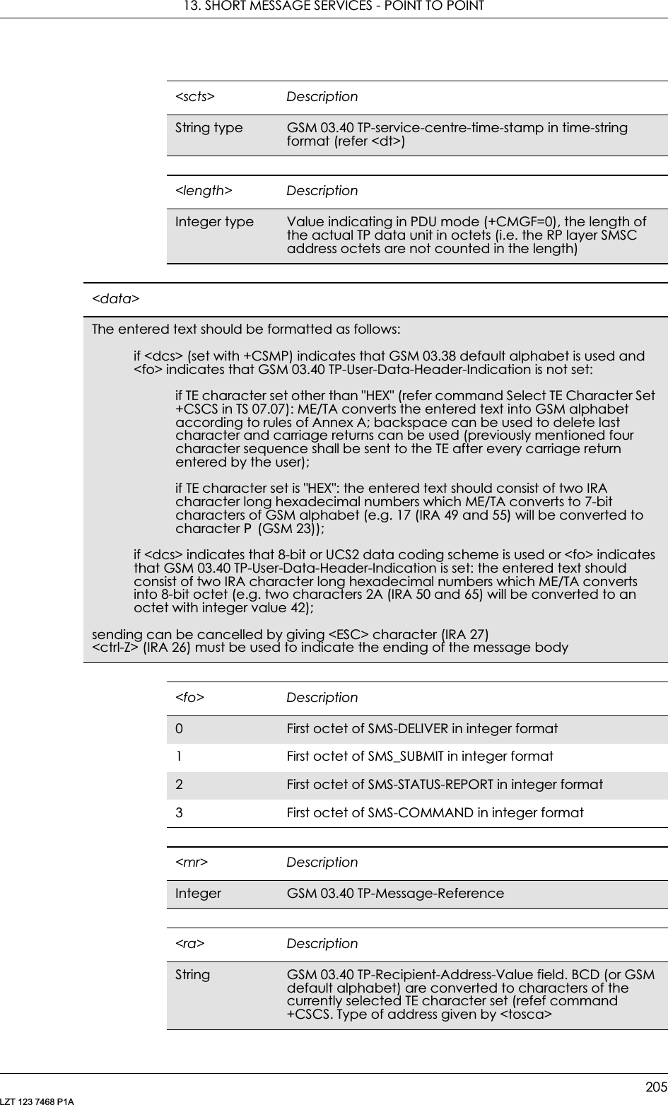
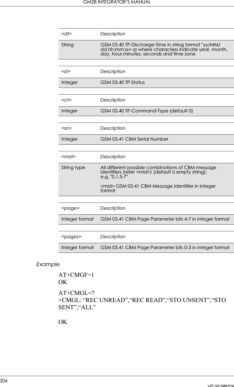
![13. SHORT MESSAGE SERVICES - POINT TO POINT207LZT 123 7468 P1A13.13 AT+CMGD Delete MessageCommon for both PDU and Text modesDeletes message from preferred message storage <mem1> location <index>. If deleting fails, final result code +CMS ERROR: <err> is returned. Test command shows the valid memory locations.13.14 AT+CSDH Show Text Mode ParametersOnly Applicable to Text ModeControls whether detailed header information is shown in text mode result codes.Description Command Possible ResponsesDelete message AT+CMGD=<index> • +CMS ERROR: <err>•OK•ERRORShow if the command is supported AT+CMGD=? • OK•ERROR<index> DescriptionInteger type Value in the range of location numbers supported by the associated memoryDescription Command Possible ResponsesSet the show text modeAT+CSDH=[<show>] • +CME ERROR: <err>•OKDisplay current settings AT+CSDH? • +CSDH: <show>• +CME ERROR: <err>Show if the command is supported AT+CSDH=? • +CSDH: (list of supported <show>s)•OK• +CME ERROR: <err><show> Description0Do not show header values defined in commands AT+CSCA and AT+CSMP (<sca>, <tosca>, <fo>, <vp>, <pid> and <dcs>) nor <length>, <toda> or <tooa> in +CMT, +CMGL, +CMGR result codes for SMS-DELIVERs and SMS-SUBMITs in text mode; for SMS-COMMANDs in +CMGR result code, do not show <pid>, <mn>, <da>, <toda>, <length> or <cdata>1 Show the values in result codes](https://usermanual.wiki/Sony/6220502-BV.Integrators-User-Manual/User-Guide-324170-Page-207.png)
![GM28 INTEGRATOR’S MANUAL208LZT 123 7468 P1A13.15 AT+CSMP Set Text Mode ParametersOnly Applicable to Text ModeUsed to select values for additional parameters needed when SM is sent to the network or placed in a storage when text format message mode is selected. It is possible to set the validity period starting from when the SM is received by the SMSC (<vp> is in range 0… 255). The <pid> parameter identifies the higher protocol being used or indicates interworking with a certain type of telematic service and <dcs> determines the way the information is encoded as in GSM 03.38.Description Command Possible ResponsesSet the text mode parametersAT+CSMP=[<fo> [,<vp>[,<pid> [,<dcs>]]]]• +CME ERROR: <err>•OK•ERRORDisplay current settingsAT+CSMP? • +CSMP: <fo>,<vp>,<pid>,<dcs>• +CME ERROR: <err>Show if the command is supported AT+CSMP=? • +CSMP: (List of supported <fo>s), (list of supported <vp>s), (list of supported <pid>s), (list of supported <dcs>s)• +CME ERROR: <err>•OK•ERROR<fo> Description0-255 Depending on the command or result code: first octet of GSM 03.40 SMS-DELIVER, SMS-SUBMIT (default value 17),SMS-STATUS-REPORT, or SMS-COMMAND (default value 2) in integer format<vp> Description0-143 (TP-VP+1) x 5 minutes (i.e 5 minutes intervals up to 12 hous)144-167 12 hours + ((TP_VP-143) x 30 minutes)168-196 (TP-VP-166) x 1 day197-255 (TP-VP-192) x 1 week<pid> Description0-255 Protocol Identifier in integer format. Default value is 0, according to 07.05 section 9.2.3.9<dcs> Description0-255 Data coding scheme. See GSM 03.38. UCS2 and compressed text not supported](https://usermanual.wiki/Sony/6220502-BV.Integrators-User-Manual/User-Guide-324170-Page-208.png)
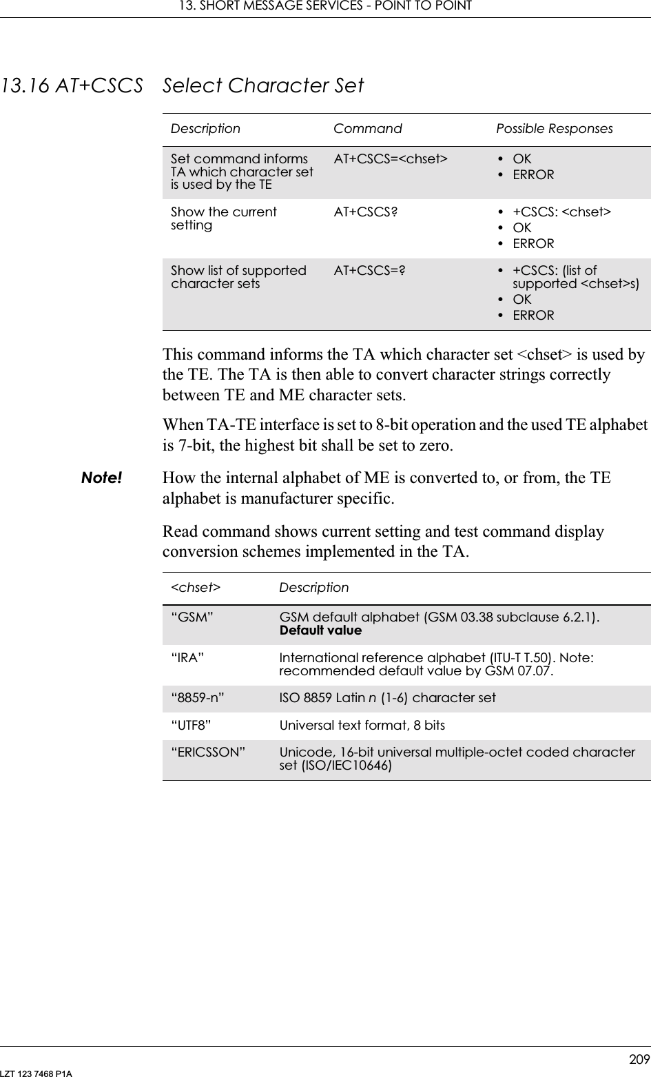
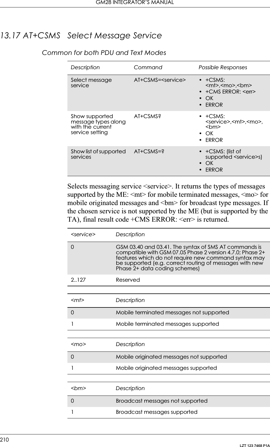
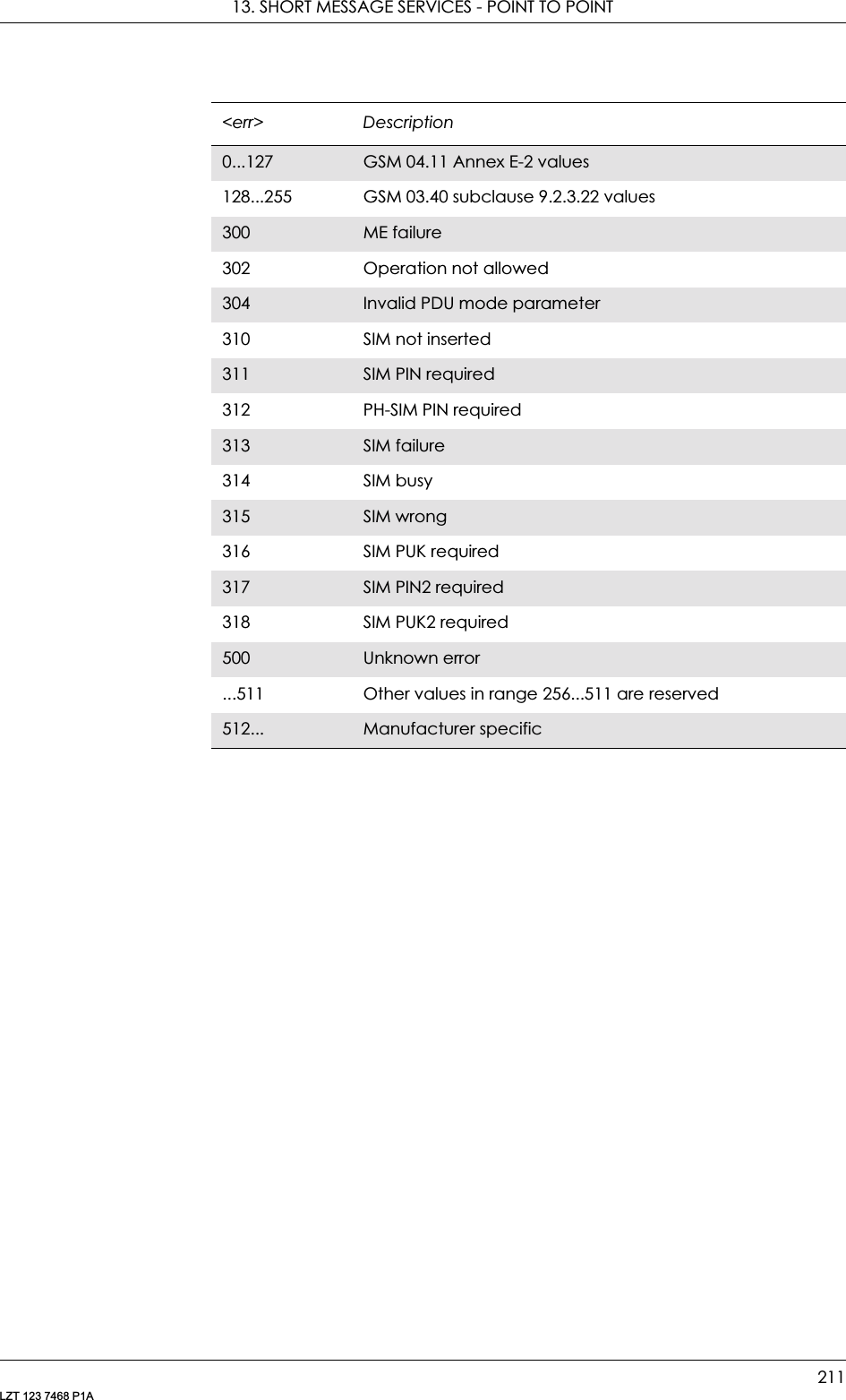
![213LZT 123 7468 P1A14. Short Message Services - Cell Broadcast14.1 AT+CNMI New Message Indications to TESee 13.10, AT+CNMI New Message Indications to TE14.2 AT+CSCB Select Cell Broadcast Message TypeCommon for both PDU and text modesSelects which types of CBMs are to be received by the ME.Description Command Possible ResponsesSelect cell broadcast message typeAT+CSCB=[<mode>[,<mids>]]• +CMS ERROR: <err>•OK•ERRORShows the current settingAT+CSCB? • +CSCB: <mode>,<mids>•OK•ERRORShow if the command is supportedAT+CSCB=? • +CSCB: (list of supported <mode>s)•OK•ERROR<mode> Description0Message types in <mids> and <dcss> are accepted<mids> Descriptionstring type All different possible combinations of CBM message identifiers (refer <mid>) (default is empty string);e.g. “0,1,5-7”<mid> GSM 03.41 CBM Message Identifier in integer format](https://usermanual.wiki/Sony/6220502-BV.Integrators-User-Manual/User-Guide-324170-Page-213.png)

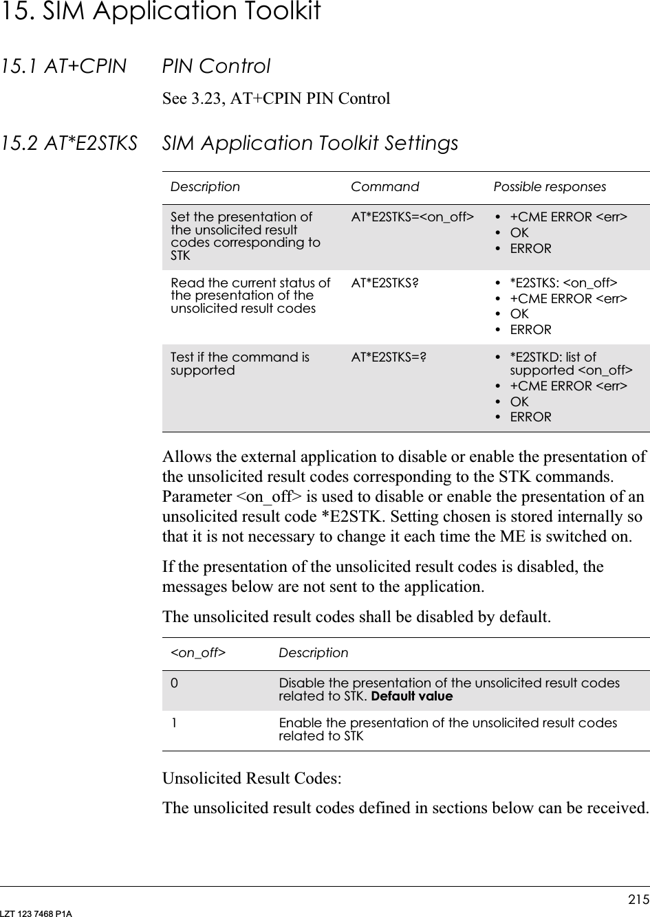
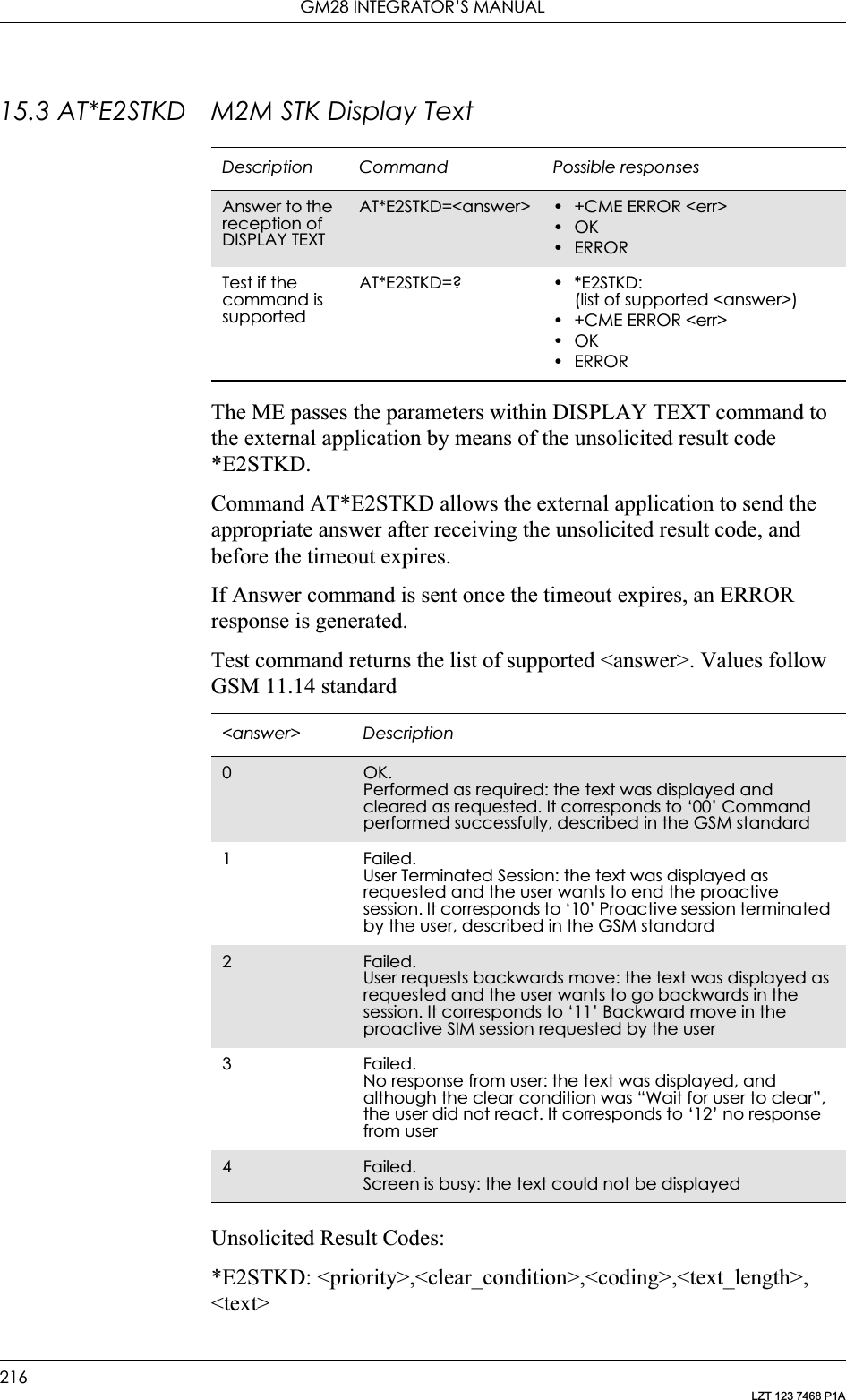
![15. SIM APPLICATION TOOLKIT217LZT 123 7468 P1AValues follow GSM 11.14 standard.15.4 AT*E2STKG M2M STK Get InkeyThe ME passes the parameters within GET INKEY command to the external application by means of the unsolicited result code E2STKG.The external application then sends AT*E2STKG with the user response.<priority> Description0Display normal priority text1 Display high priority text<clear_condition> Description0Clear message after a dalay1 Wait for user to clear message<coding> Description0Text is coded in unpacked format, using the SMS default 7-bit coded alphabet, as defined in GSM 03.38 with bit 8 set to 0. It corresponds to data coding scheme of 8 bit1 Text is coded in packed format, using the SMS default 7-bit coded alphabet, packed in 8-bit octets, as defined in GSM 03.38. It corresponds to data coding scheme of 7 bit GSM default alphabet<text_length> DescriptionIntegter type Value indicating the maximum length of field <text><text> Descriptionstring type Field of maximum length <text_length>, in string type format between "". Coding is defined in <coding>Description Command Possible responsesAnswer to the reception of GET INKEYAT*E2STKG =<answer>, [<response_type>, <user_response>]• +CME ERROR <err>•OKTest if the command is supportedAT*E2STKG=? • *E2STKG: (list of supported <answer>),(list of supported <response_type>),<user_response>• +CME ERROR <err>•OK•ERROR](https://usermanual.wiki/Sony/6220502-BV.Integrators-User-Manual/User-Guide-324170-Page-217.png)
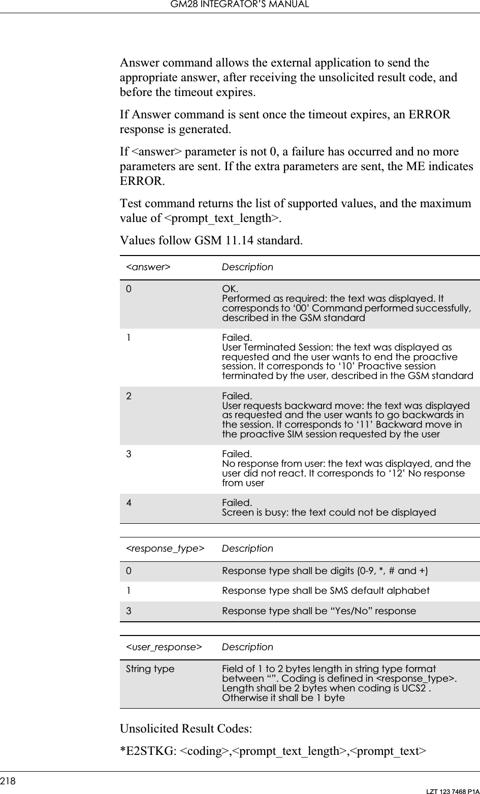
![15. SIM APPLICATION TOOLKIT219LZT 123 7468 P1AValues follow GSM 11.14 standard.15.5 AT*E2STKI M2M STK Get InputThe ME passes the parameters within GET INPUT command to the external application by means of the unsolicited result code E2STKI. The external application sends AT*E2STKI with the user response.AT*E2STKI allows the external application to send the appropriate answer after receiving the unsolicited result code, and before the timeout expires.If Answer command is sent once the timeout expires, an ERROR response is generated.If <answer> parameter is not 0, a failure has occurred and no more parameters are sent. If the extra parameters are sent, the ME indicates ERROR.<coding> Description0Text is coded in unpacked format, using the SMS default 7-bit coded alphabet, as defined in GSM 03.38 with bit 8 set to 0. It corresponds to data coding scheme of 8 bit1 Text is coded in packed format, using the SMS default 7-bit coded alphabet, packed in 8-bit octets, as defined in GSM 03.38. It corresponds to data coding scheme of 7 bit GSM default alphabet<prompt_text_length> DescriptionInteger type (0-235) Value indicating the maximum length of field <prompt_text><prompt_text> DescriptionString type Field of maximum length <prompt_text_length>, in string type format between “”. Coding is defined in <prompt_coding>.Description Command Possible responsesAnswer to the reception of GET INPUT AT*E2STKI=<answer>, [<response_type>, <response_length>, <user_response>]• +CME ERROR <err>•OK•ERRORTest if the command is supportedAT*E2STKI=? • *E2STKI: (list of supported <answer>),(list of supported <response_type>),<response_length>,<user_response>• +CME ERROR <err>•OK•ERROR](https://usermanual.wiki/Sony/6220502-BV.Integrators-User-Manual/User-Guide-324170-Page-219.png)
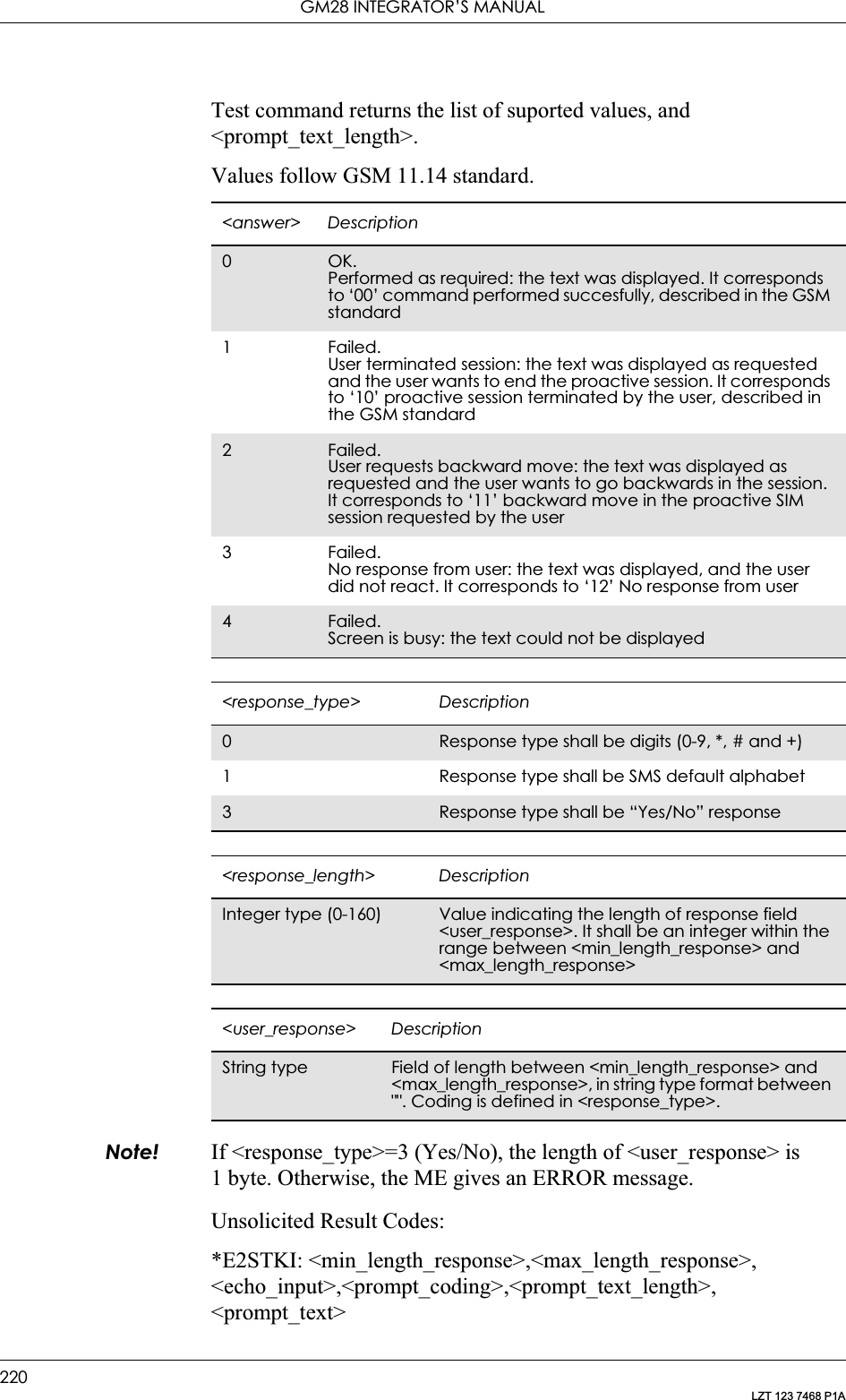
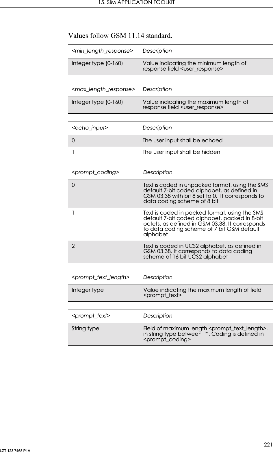
![GM28 INTEGRATOR’S MANUAL222LZT 123 7468 P1A15.6 AT*E2STKL M2M STK Select ItemThe ME passes the parameters within SELECT ITEM command to the external application by means of the unsolicited result code *E2STKL.Command AT*E2STKL allows the external application to send the appropriate answer after receiving the unsolicited result code, and before the timeout expires.If Answer command is sent once the timeout expires, an ERROR response is be generated.If <answer> parameter is not 0, a failure has occurred and no more parameters are sent. If the extra parameters are sent, the ME indicates ERROR.Values follow GSM 11.14 standard.Description Command Possible responsesAnswer to the reception of SELECT ITEMAT*E2STKL=<answer>, [<user_response>]• +CME ERROR <err>•OK•ERRORTest if the command is supportedAT*E2STKL=? • *E2STKL: (list of supported <answer>),(list of supported <user_response>)• +CME ERROR <err>•OK•ERROR<answer> Description0OK.Performed as required. It corresponds to ‘00’ command performed succesfully, described in the GSM standard1 Failed.User terminated session. It corresponds to ‘10’ Proactive session terminated by the user, described in the GSM standard2Failed.User requests backwards move. It corresponds to ‘11’ Backward move in the proactive SIM session requested by the user3 Failed.No response from user. It corresponds to ‘12’ no response from user4Failed.Screen is busy: the text could not be displayed<user_response> Descriptioninteger type The identifier is a single byte between 1 and 255. It identifies the selected <item_idn> within the items list](https://usermanual.wiki/Sony/6220502-BV.Integrators-User-Manual/User-Guide-324170-Page-222.png)
![15. SIM APPLICATION TOOLKIT223LZT 123 7468 P1AUnsolicited Result Codes:E2STKL: <NbrOfItems>,<coding>,<text_length>,<alpha_id>[,<default>]<CR><LF>E2STKL: <item_id1>,<coding>, <text_length>,<item1><CR><LF>[…]E2STKL: <item_idn>, <coding>,<text_length>,<itemn><CR><LF>]Values follow GSM 11.14 standard.The maximum length is fixedThe maximum length is fixed.<coding> Description0 Text is coded in unpacked format, using the SMS default 7-bit coded alphabet, as defined in GSM 03.38 with bit 8 set to 0. It corresponds to data coding scheme of 8 bit1 Text is coded in packed format, using the SMS default 7-bit coded alphabet, packed in 8-bit octets, as defined in GSM 03.38. It corresponds to data coding scheme of 7 bit GSM default alphabet<text_length> DescriptionInteger type(0-240)Value indicating the maximum length of field <alpha_id>, <itemn1>,.<Itemn><alpha_id> DescriptionString type Field of string type between “”. Coding is according to EFAND as defined in GSM 11.11<default> DescriptionInteger type The <default> parameter is a single byte between 1 and 255. It shows the default/selected item within the list<item_idn> DescriptionInteger type The identifier is a single byte between 1 and 255. Each item <itemn> in the list shall have a unique identifer <item_idn><itemn> DescriptionString type Field of string type between “”. Coding is according to EFAND as defined in GSM 11.11<NbrOfItems> DescriptionInteger type Number of items to be presented in the following unsolicited results](https://usermanual.wiki/Sony/6220502-BV.Integrators-User-Manual/User-Guide-324170-Page-223.png)
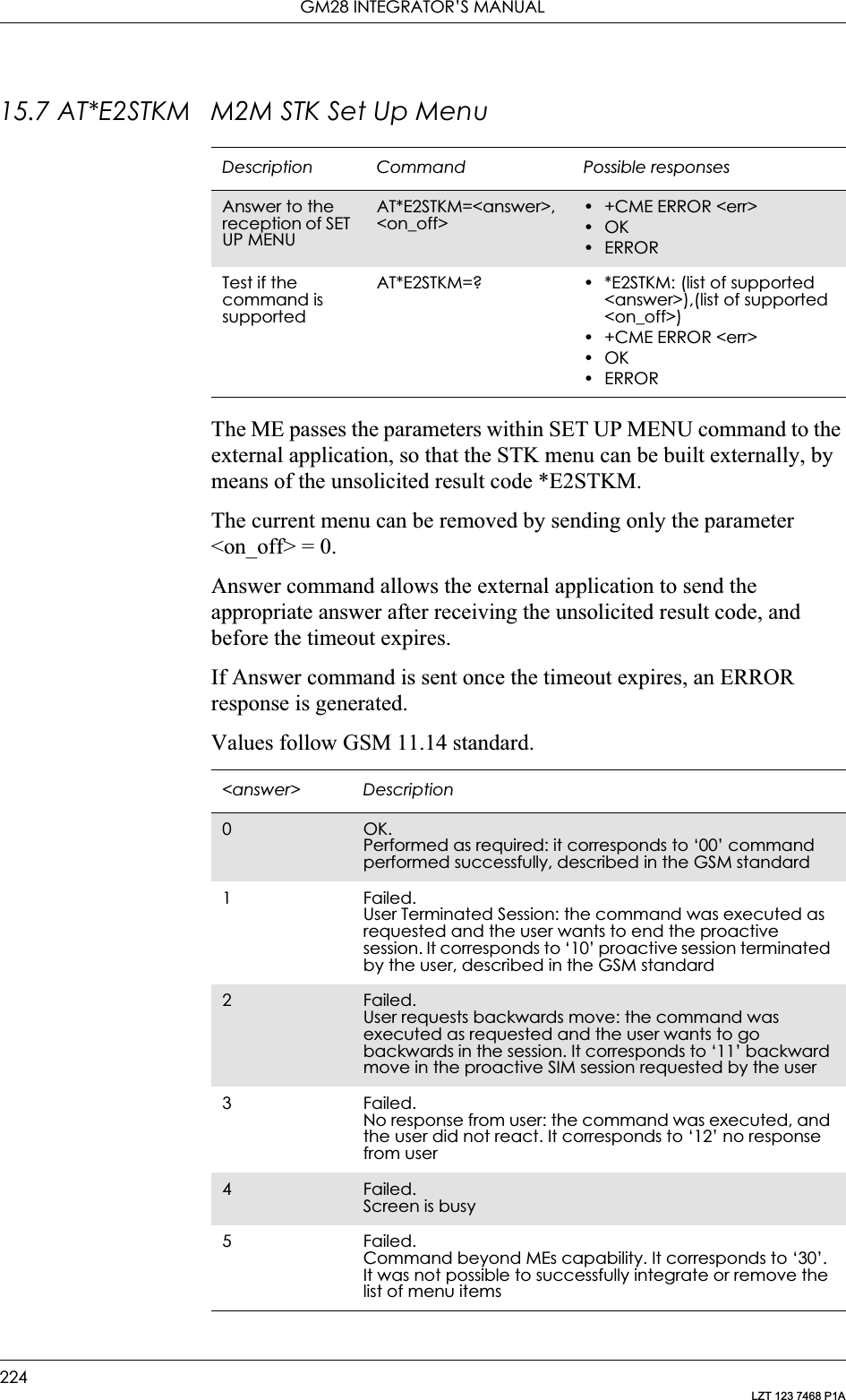
![15. SIM APPLICATION TOOLKIT225LZT 123 7468 P1AUnsolicited Result Codes:*E2STKM: <NbrOfItems>,<coding>,<text_length>,<alpha_id><CR><LF>E2STKM: <item_id1>,<coding>, <text_length>,<item1>[<CR><LF>[…]E2STKM: <item_idn>,<coding>,<text_length>,<itemn>]Values follow GSM 11.14 standard.The maximum length is fixed.The maximum length is fixed.<on_off> Description0Remove the current menu1 New menu to be displayed<coding> Description0Text is coded in unpacked format, using the SMS default 7-bit coded alphabet, as defined in GSM 03.38 with bit 8 set to 0. It corresponds to data coding scheme of 8 bit1 Text is coded in packed format, using the SMS default 7-bit coded alphabet, packed in 8-bit octets, as defined in GSM 03.38. It corresponds to data coding scheme of 7 bit GSM default alphabet<text_length> DescriptionInteger type Value indicating the maximum length of field <alpha_id>, <itemn1>, <Itemn><alpha_id> DescriptionString type Field of string type between "". Coding is according to EFAND as defined in GSM 11.11<item_idn> DescriptionInteger type The identifier is a single byte between 1 and 255. Each item <itemn> in the list shall have a unique identifer <item_idn><itemn> DescriptionString type Field of string type format between “”. Coding is according to EFAND as defined in GSM 11.11<NbrOfltems> DescriptionInteger type Number of Items to be presented in the following unsolicited results](https://usermanual.wiki/Sony/6220502-BV.Integrators-User-Manual/User-Guide-324170-Page-225.png)
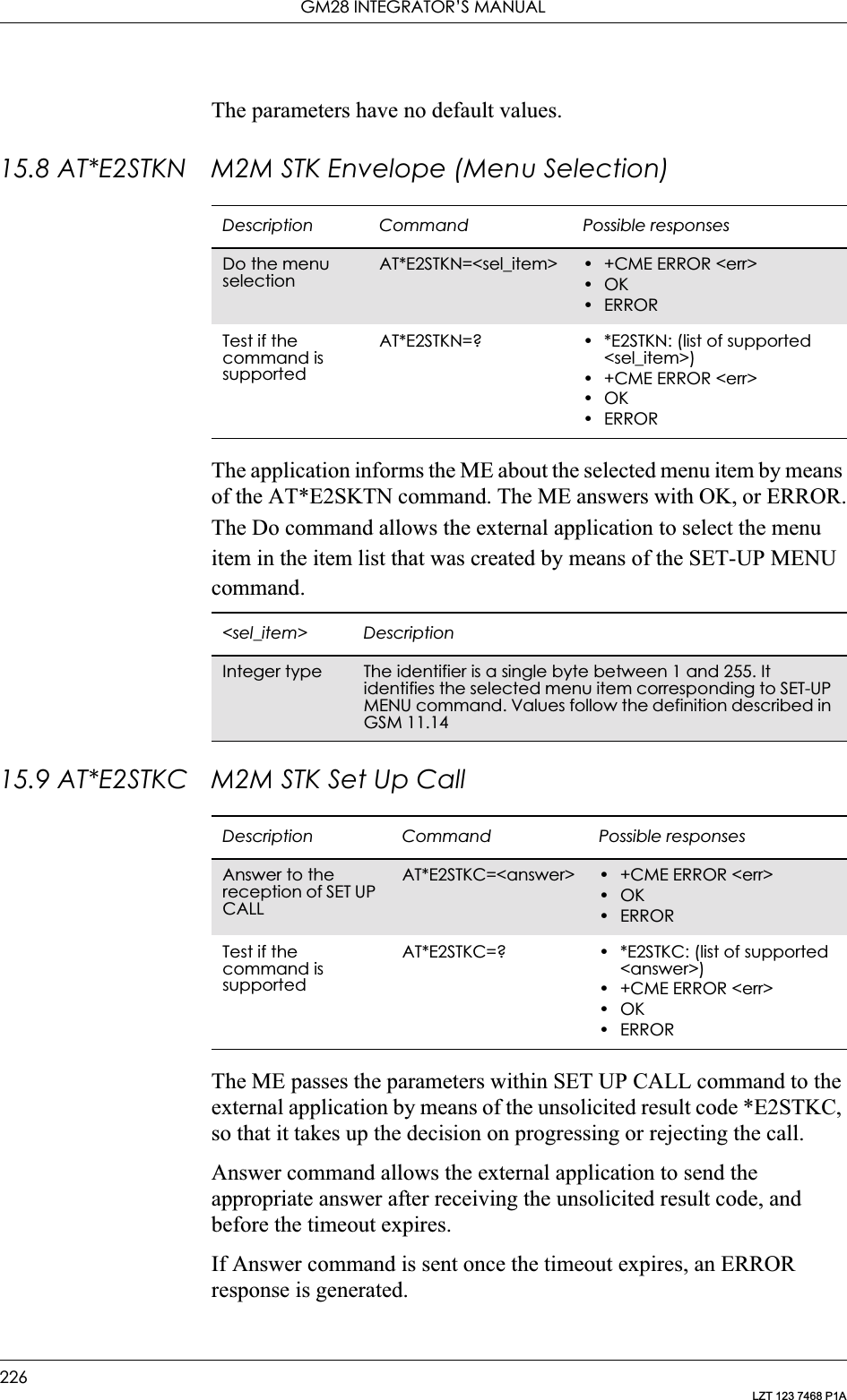
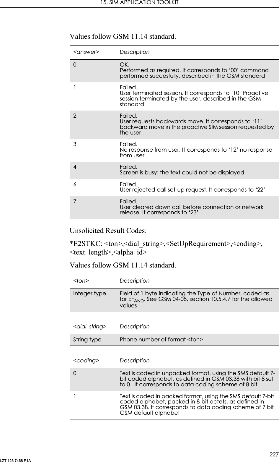
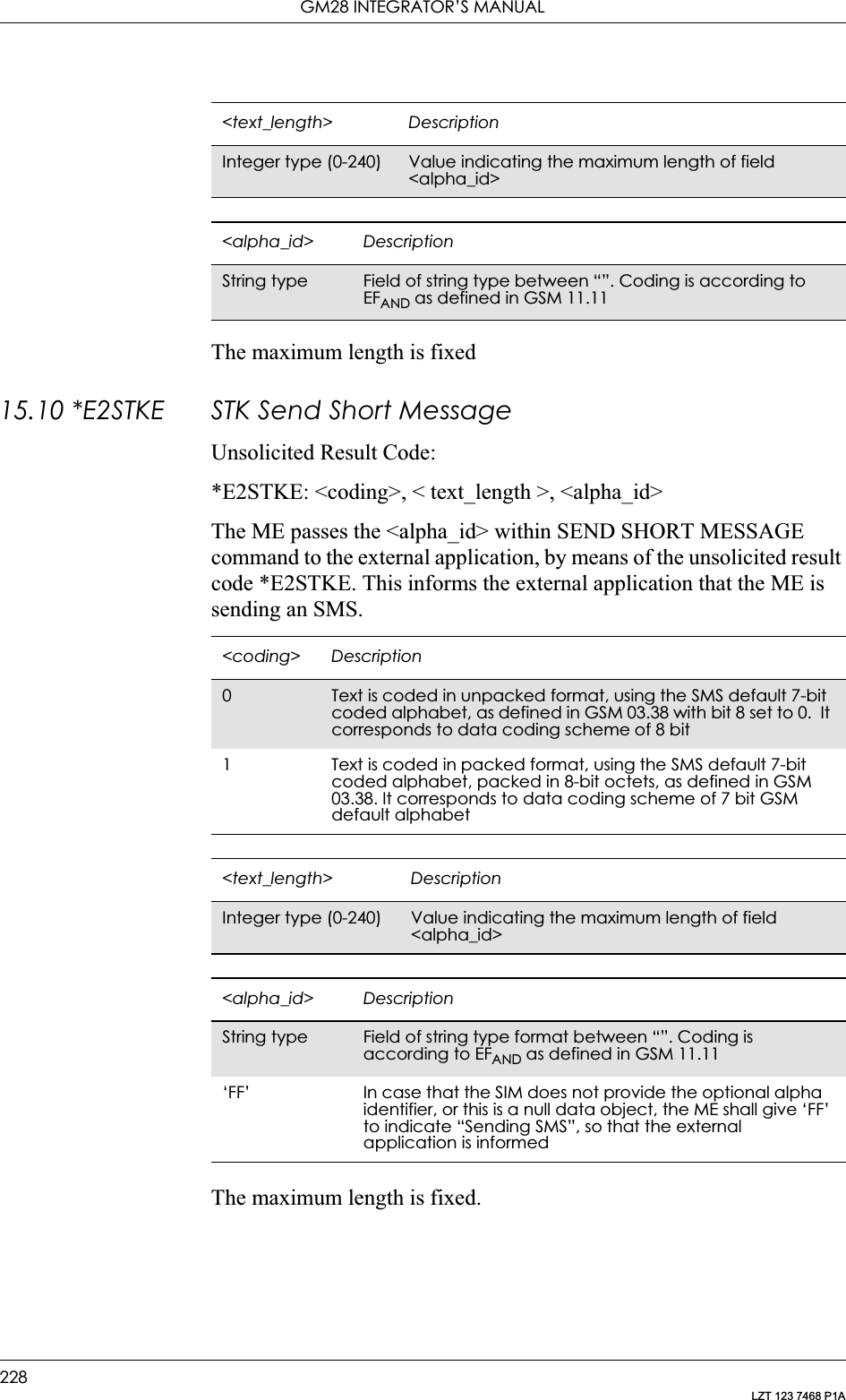
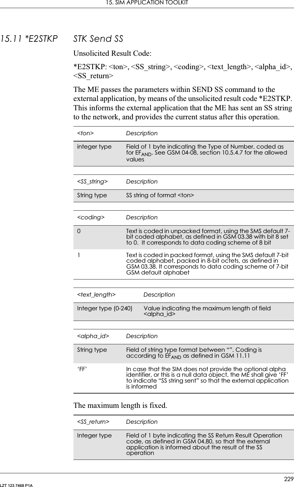
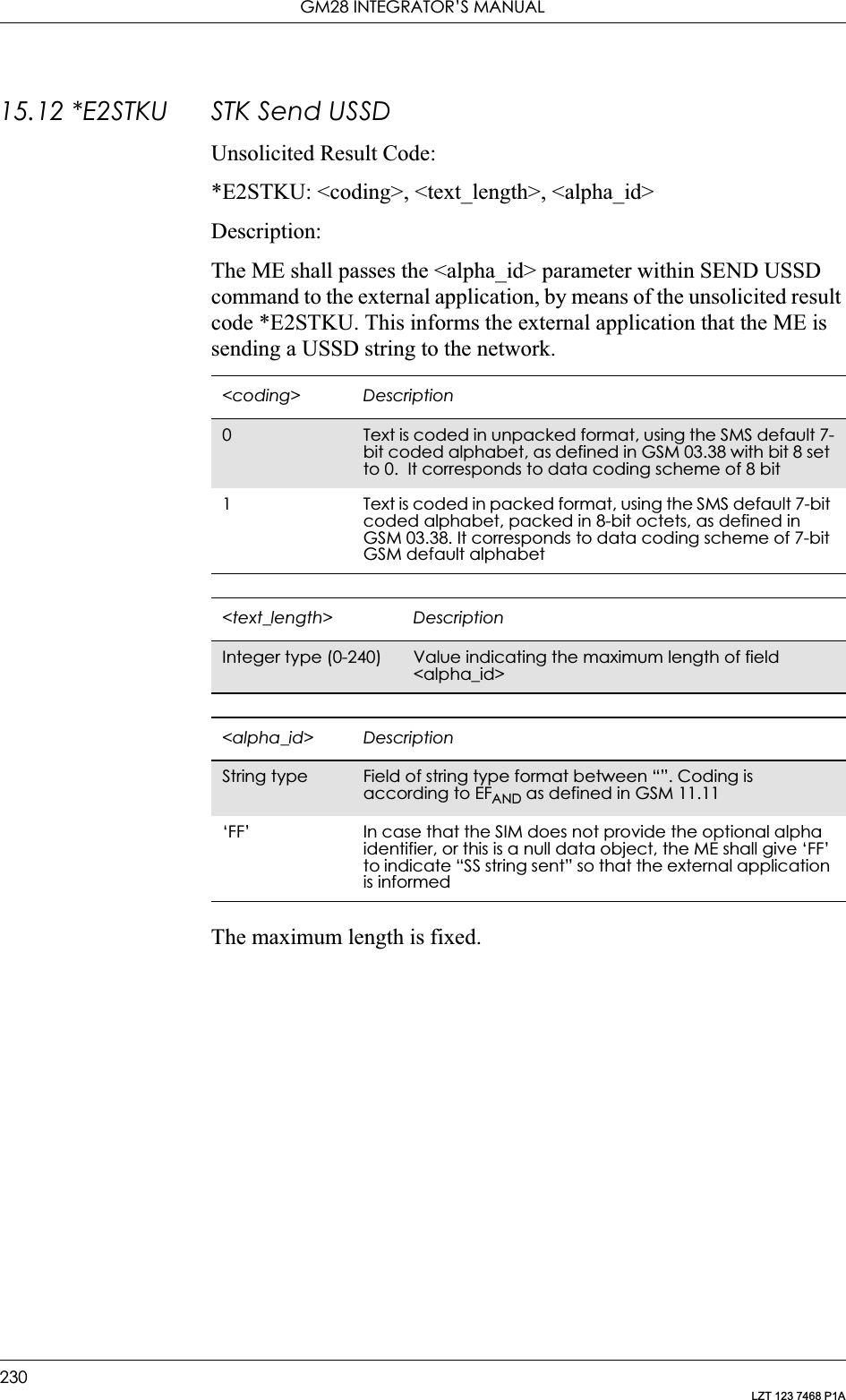
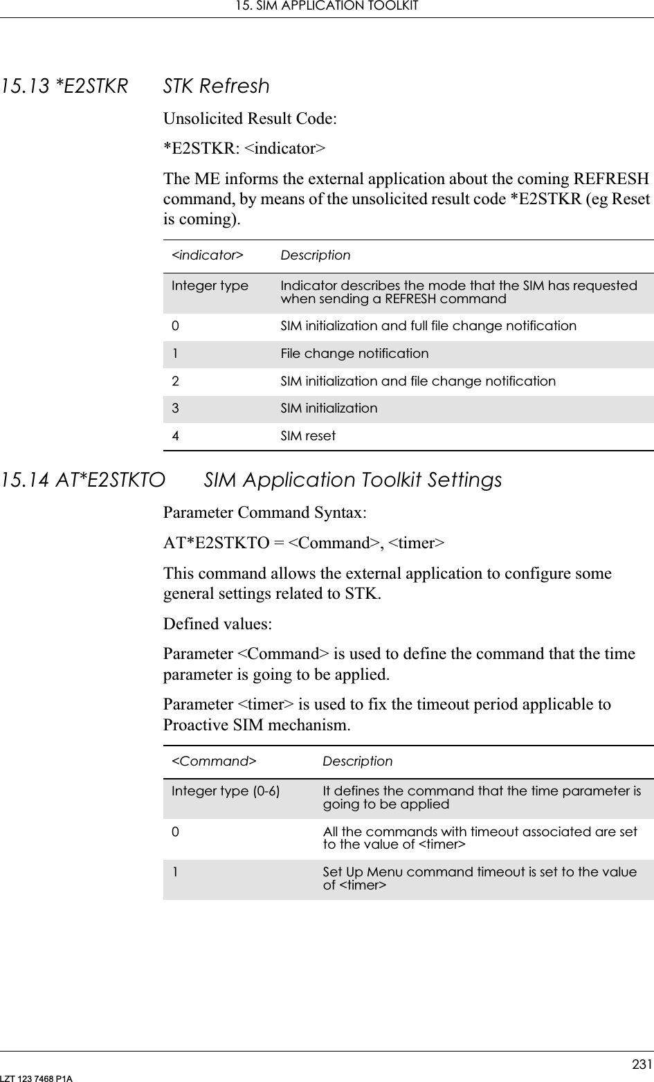
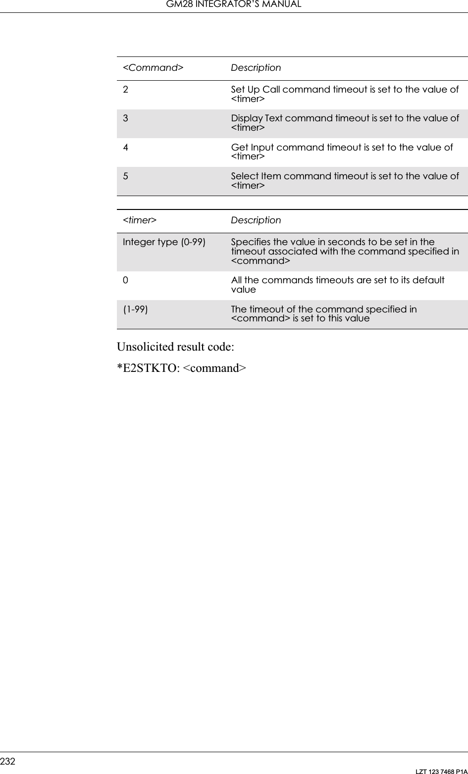
![233LZT 123 7468 P1A16. Supplementary Services16.1 AT+CPIN PIN ControlSee 3.23, AT+CPIN PIN Control16.2 AT+CACM Accumulated Call MeterResets the Advice of Charge related accumulated call meter value in SIM file EFACM. ACM contains the total number of home units for both the current and preceding calls. SIM PIN2 is usually required to reset the value. If setting fails in an ME error, +CME ERROR: <err> is returned. See “+CME ERROR (Mobile Equipment Error Code)”, page 55.Note! This command must take into account what line is chosen with AT*ELIN.Read command returns the current value of ACM.Description Command Possible ResponsesReset the ACM (Accumulated Call Meter) value on the SIMAT+CACM=[<passwd>] • +CME ERROR: <err>•OK•ERRORShow the current value AT+CACM? • +CACM: <acm>+CME ERROR: <err>•OK•ERRORTests if the command is supportedAT+CACM=? • +CME ERROR: <err>•OK•ERROR<passwd> DescriptionString type SIM-PIN2 <acm> DescriptionString type Accumulated call meter value similarly coded as <ccm> under +CAOC](https://usermanual.wiki/Sony/6220502-BV.Integrators-User-Manual/User-Guide-324170-Page-233.png)
![GM28 INTEGRATOR’S MANUAL234LZT 123 7468 P1A16.3 AT+CAMM Accumulated Call Meter MaximumSets the Advice of Charge related accumulated call meter maximum value in SIM file EFACMmax. ACMmax contains the maximum number of home units allowed to be consumed by the subscriber. When ACM (refer +CACM) reaches ACMmax calls are prohibited. SIM PIN2 is usually required to set the value. If setting fails in an ME error, +CME ERROR: <err> is returned.Read command returns the current value of ACMmax.Description Command Possible ResponsesSet command sets the Advice of Charge related accumulated call meter maximum value in SIM file EFACMmaxAT+CAMM=[<acmmax>[,<passwd>]]• +CME ERROR: <err>•OK•ERRORRead the current valueAT+CAMM? • +CAMM: <acmmax>+CME ERROR: <err>•OK•ERRORTest if the command if supportedAT+CAMM=? • +CME ERROR: <err>•OK•ERROR<acmmax> DescriptionString type Accumulated call meter maximum value similarly coded as <ccm> under +CAOC; value zero disables ACMmax feature<passwd> DescriptionString type SIM PIN2](https://usermanual.wiki/Sony/6220502-BV.Integrators-User-Manual/User-Guide-324170-Page-234.png)
![16. SUPPLEMENTARY SERVICES235LZT 123 7468 P1A16.4 AT+CAOC Advice of ChargeUse of Advice of Charge supplementary service command enables the subscriber to get information about the cost of calls. With <mode>=0, the execute command returns the current call meter value from the ME. The command also includes the possibility to enable an unsolicited event reporting of the CCM information. The unsolicited result code +CCCM: <ccm> is sent when the CCM value changes, but no more than every 10 seconds. Deactivation of the unsolicited event reporting is made with the same command.Read command indicates whether the unsolicited reporting is activated or not. Read command is available when the unsolicited result code is supported.It is recommended (although optional) that the test command return the supported mode values.Description Command Possible ResponsesExecute command AT+CAOC[=<mode>] • [+CAOC: <ccm>]+CME ERROR: <err>•OK•ERRORRead command, shows the current modeAT+CAOC? • +CAOC: <mode>•OK•ERRORTest command, shows if the command is supportedAT+CAOC=? • [+CAOC: (list of supported <mode>s]•OK•ERROR<mode> Description0Query CCM value1 Deactivate the unsolicited reporting of CCM value2Activate the unsolicited reporting of CCM value<ccm> DescriptionString type Three bytes of the current call meter value in hexadecimal format (e.g. “00001E” indicates decimal value 30); value is in home units and bytes are similarly coded as ACMmax value in the SIM](https://usermanual.wiki/Sony/6220502-BV.Integrators-User-Manual/User-Guide-324170-Page-235.png)
![GM28 INTEGRATOR’S MANUAL236LZT 123 7468 P1A16.5 AT+CPUC Price Per Unit and Currency TableSets the parameters of Advice of Charge related price per unit and currency table in SIM file EFPUCT. PUCT information can be used to convert the home units (as used in +CAOC, +CACM and +CAMM) into currency units. SIM PIN1 or SIM PIN2 (depending on which SIM card that is used) is required to set the parameters. If setting fails in an ME error, +CME ERROR: <err> is returned.Read command returns the current parameters of PUCT.For information on the character set see AT+CSCS in the Short Message Services section.Description Command Possible ResponsesSet command sets the parameters of Advice of Charge related price per unit and currency table in SIM file EFPUCTAT+CPUC=<currency>,<ppu>[,<passwd>]• +CME ERROR: <err>•OK•ERRORShows the current valuesAT+CPUC? • +CPUC: <currency>,<ppu>+CME ERROR: <err>•OK•ERRORShows if the command is supportedAT+CPUC=? •OK•ERROR<currency> DescriptionString Alpha-identifier of the currency code (3 characters, e.g. SEK)<ppu> DescriptionString type price per unit; dot is used as a decimal separator (e.g. “2.66”)<passwd> DescriptionString type SIM PIN1 or SIM PIN2](https://usermanual.wiki/Sony/6220502-BV.Integrators-User-Manual/User-Guide-324170-Page-236.png)
![16. SUPPLEMENTARY SERVICES237LZT 123 7468 P1A16.6 AT*EDIF Ericsson Divert FunctionThis command enables and disables notification of divert status changes with the unsolicited result code *EDIF.Unsolicited Result Codes:*EDIF: <reason>,<status>,<classx>[,<number>,<type>]Description Command Possible ResponsesEnable and disable notification with the unsolicited result code *EDIFAT*EDIF=<onoff> • +CME ERROR: <err>•OK•ERRORShow the current settingAT*EDIF? • *EDIF: <onoff>+CME ERROR: <err>•OK•ERRORShow if the command is supportedAT*EDIF=? • *EDIF: (list of supported <onoff>s)• +CME ERROR: <err>•OK•ERROR<onoff> Description0Disable notification with the unsolicited result code *EDIF1 Enable notification with the unsolicited result code *EDIF](https://usermanual.wiki/Sony/6220502-BV.Integrators-User-Manual/User-Guide-324170-Page-237.png)
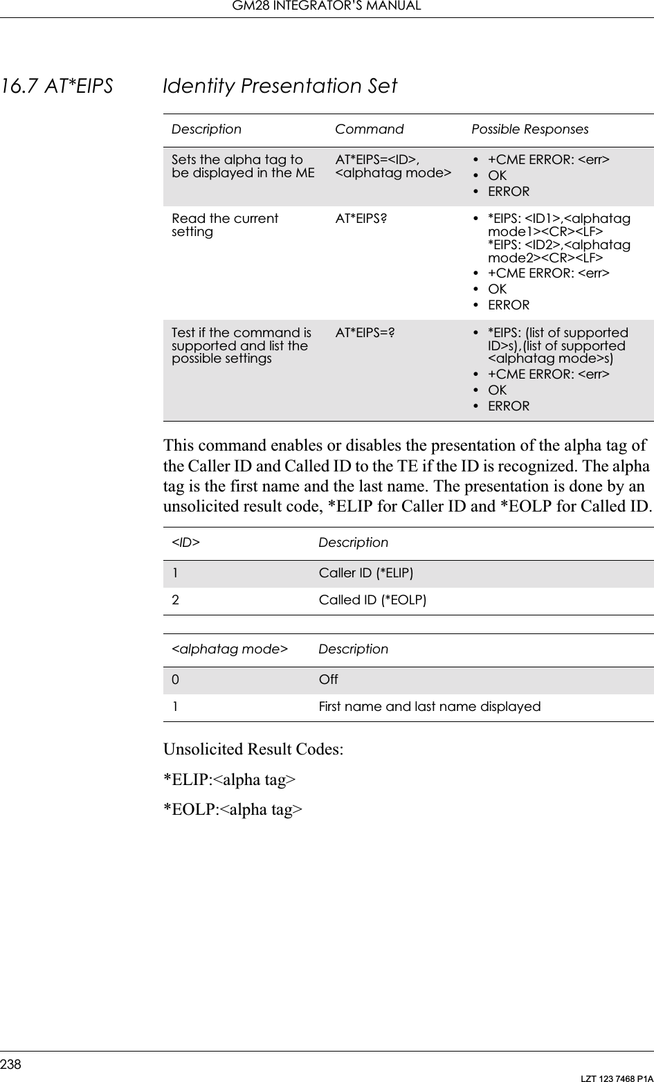
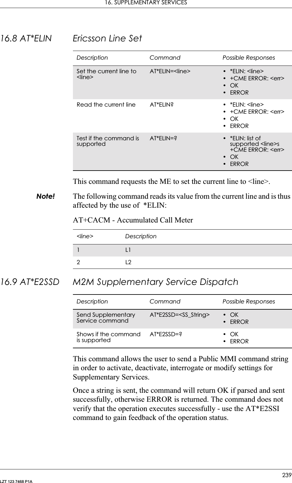
![GM28 INTEGRATOR’S MANUAL240LZT 123 7468 P1ARefer to GSM 02.30 for Public MMI services and codes.16.10 AT*E2SSI M2M Supplementary Service IndicationsThis command allows the user to display the unsolicited response code *E2SSI on network responses (either command confirmation or error responses) for Supplementary Services. This can be used in conjunction with the AT+CSSN command which gives responses on the network notification of SS status.The default setting is OFF, where responses are disabled.Unsolicited Result codes:*E2SSI: <errorcode>[,<Opcode>[,<SS_Code>,[<BasicServChoice>, <BasicServValue>],[<SS_Status>],[<ForwardedToNr>], [<NoReplyConditionTime>], [<CLI_RestrictionOption>]]]or*E2SSI: <errorcode>[,<Opcode>[,<SS_Code>,[<BasicServChoice>, <BasicServValue>],[<SS_Status>],[<SubscriptionOption>]]]<SS_String> DescriptionString Type String in double quotes, containing a Public MMI command to modify, activate, interrogate or deactivate a Supplementary Service. String can contain values‘0-9’, ‘*’ and ‘#’Description Command Possible ResponsesSet Supplementary Service indicationsAT*E2SSI=<op> •ERROR•OKDisplays current settingsAT*E2SSI? *E2SSI: <op>Shows if the command is supportedAT*E2SSI=? • *E2SSI: (list of supported <op>s)•ERROR<op> Description0Disable *E2SSI indications. Default value1 Enable *E2SSI indications<errorcode> Description0OK (no error)1 SSI_PASSWORD_ERROR2SSI_TOO_MANY_PARTS3 SSI_COMMAND_ERROR](https://usermanual.wiki/Sony/6220502-BV.Integrators-User-Manual/User-Guide-324170-Page-240.png)
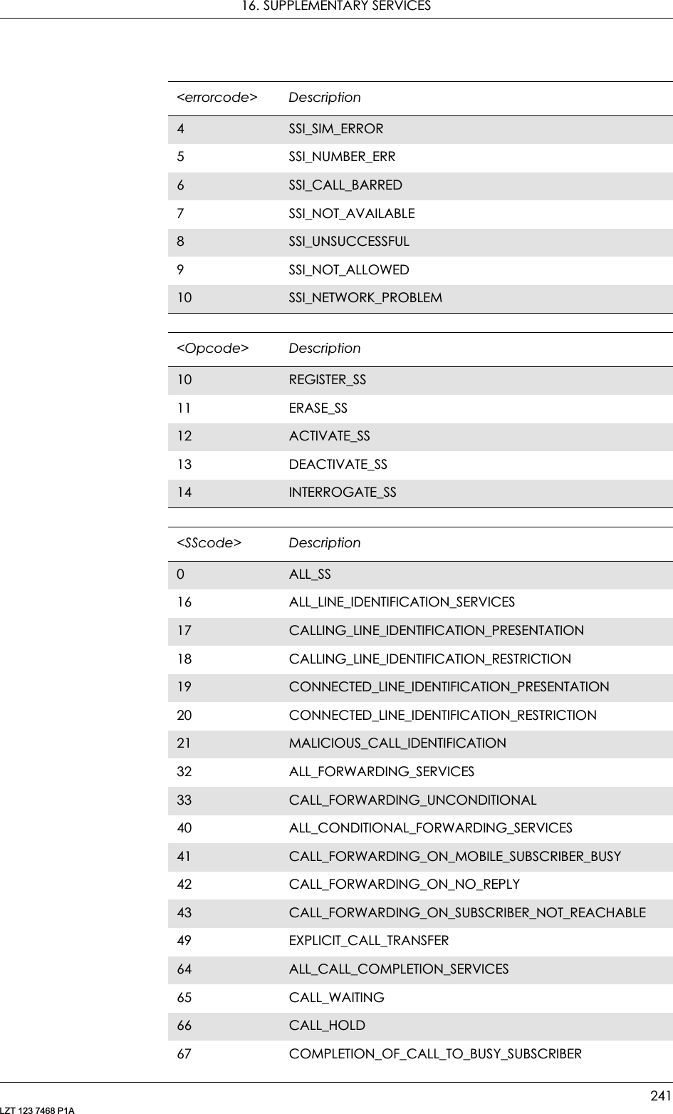
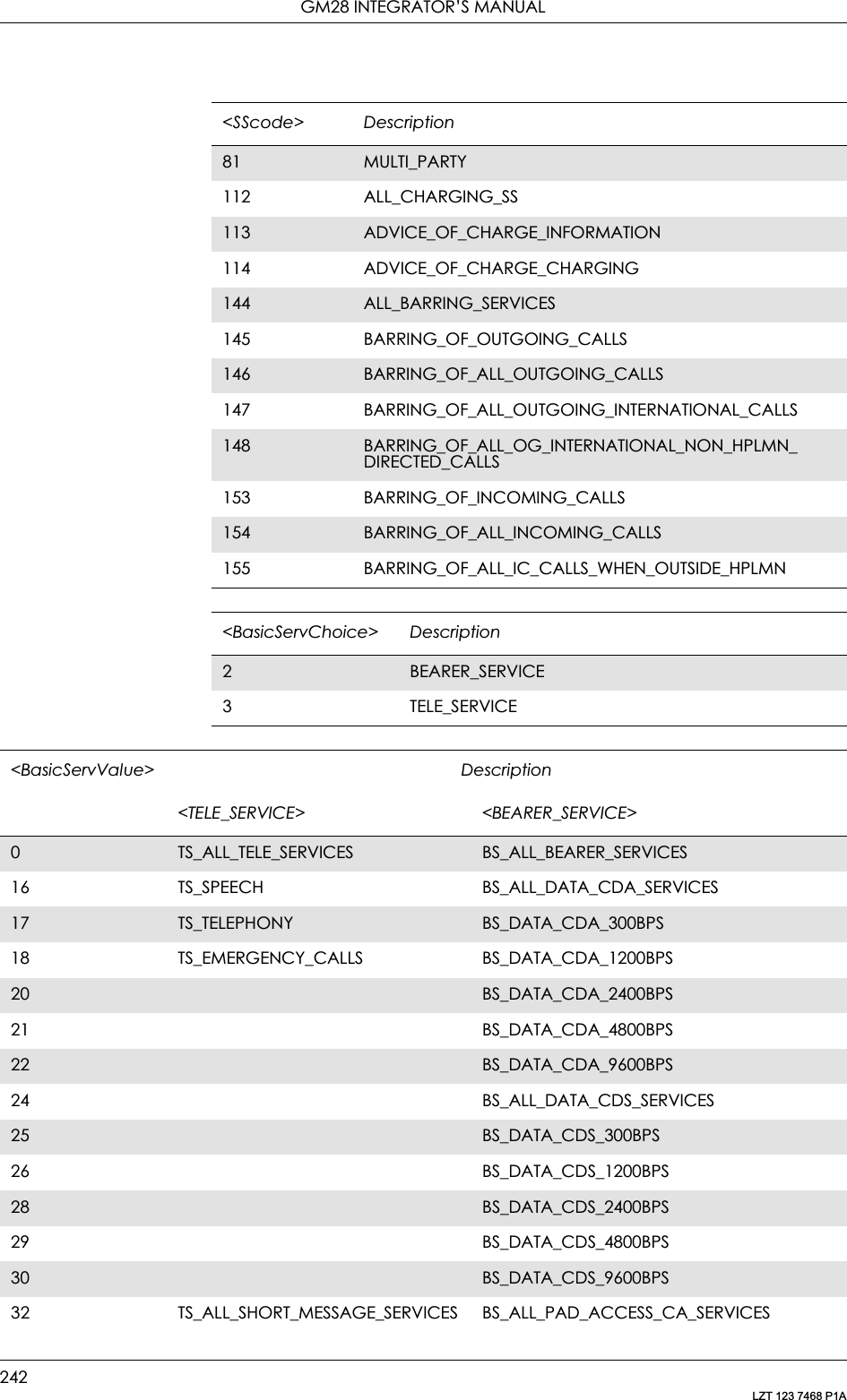
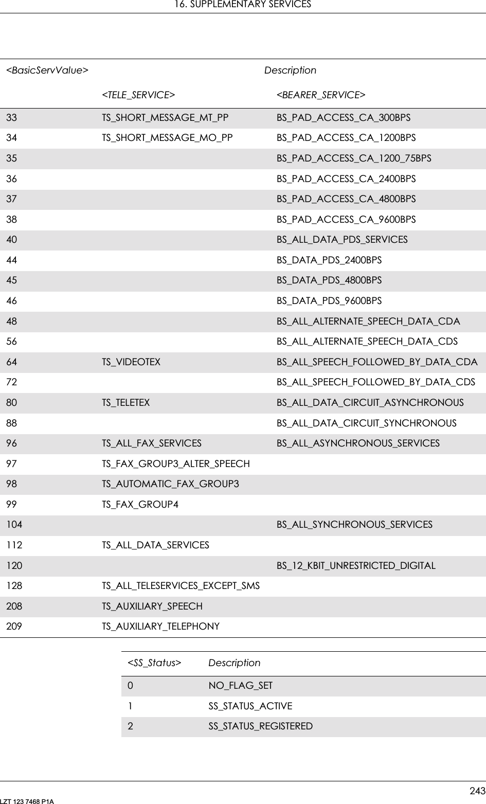
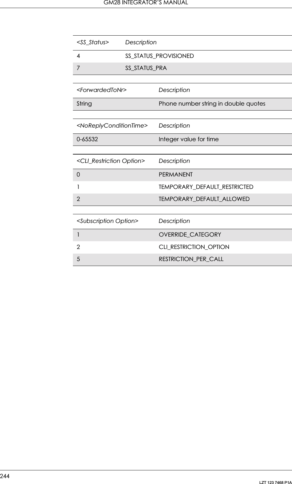
![16. SUPPLEMENTARY SERVICES245LZT 123 7468 P1A16.11 AT+CCFC Call Forwarding number and ConditionsThis command allows control of the call forwarding supplementary service. Registration, erasure, activation, deactivation, and status query are supported. When querying the status of a network service (<mode>=2) the response line for ‘not active’ case (<status>=0) should be returned only if service is not active for any <class>.Description Command Possible ResponsesRequest Calling forwarding number and conditionsAT+CCFC=<reason>,<mode>[,<number>[,<type>[,<class> [,<satype>]]]]•+CME ERROR <err>• when <mode>=2 and command successful:+CCFC: <status>,<class1>[,<number>, <type>[,<satype>]][<CR><LF>+CCFC: <status>,<class2>[,<number>,<type>[,<satype>]][...]]•OK• ERRORShow if the command is supported AT+CCFC=? • + CCFC: (list of supported <reason>s)•+CME ERROR <err>•OK• ERROR<reason> Description0Unconditional1 Mobile busy2No reply3Not reachable4All call forwarding5 All conditional call forwarding<mode> Description0Disable1 Enable2Query status3 Registration4Erasure<number> Descriptionstring type String type phone number of forwarding address in format specified by <type>](https://usermanual.wiki/Sony/6220502-BV.Integrators-User-Manual/User-Guide-324170-Page-245.png)
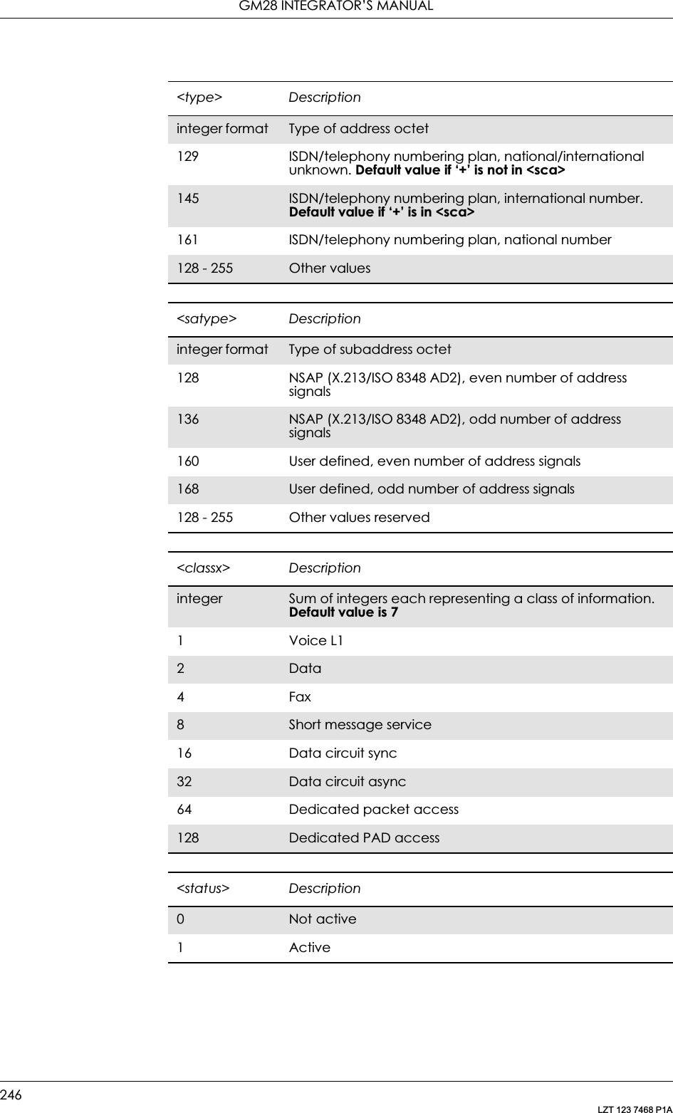
![16. SUPPLEMENTARY SERVICES247LZT 123 7468 P1A16.12 AT+CCWA Call WaitingThis command allows control of the call waiting supplementary service according to 3GPP TS 22.083. Activation, deactivation and status query are supported. When querying the status of a network service (<mode>=2) the response line for ‘not active’ case (<status>=0) should be returned only if service is not active for any <class>. Parameter <n> is used to disable or enable the presentation of an unsolicited result code +CCWA: <number>,<type>,<class>,[<alpha>][,<CLI validity>] to the TE when call waiting service is enabled. The command is abortable when the network is interrogated.The interaction of this command with other commands based on other GSM/UMTS supplementary services is described in the GSM/UMTS standards.Test command returns values supported by the TA as a compound value.Description Command Possible ResponsesRequest call waitingAT+CCWA=[<n> [,<mode>[,<class>]]]• when<mode>=2 and command successful:+CCWA:<status>,<class1>[<CR><LF>+CCWA: <status>,<class2>[…]]+CME ERROR <err>•OK•ERRORShow the current settingAT+CCWA? • +CCWA: <n>+CME ERROR <err>•OK•ERRORShow if the command is supportedAT+CCWA=? • +CCWA: (list of supported <n>s)+CME ERROR <err>•OK•ERROR<n> Description0Disable1 Enable<mode> Description0Disable1 Enable2Query status](https://usermanual.wiki/Sony/6220502-BV.Integrators-User-Manual/User-Guide-324170-Page-247.png)
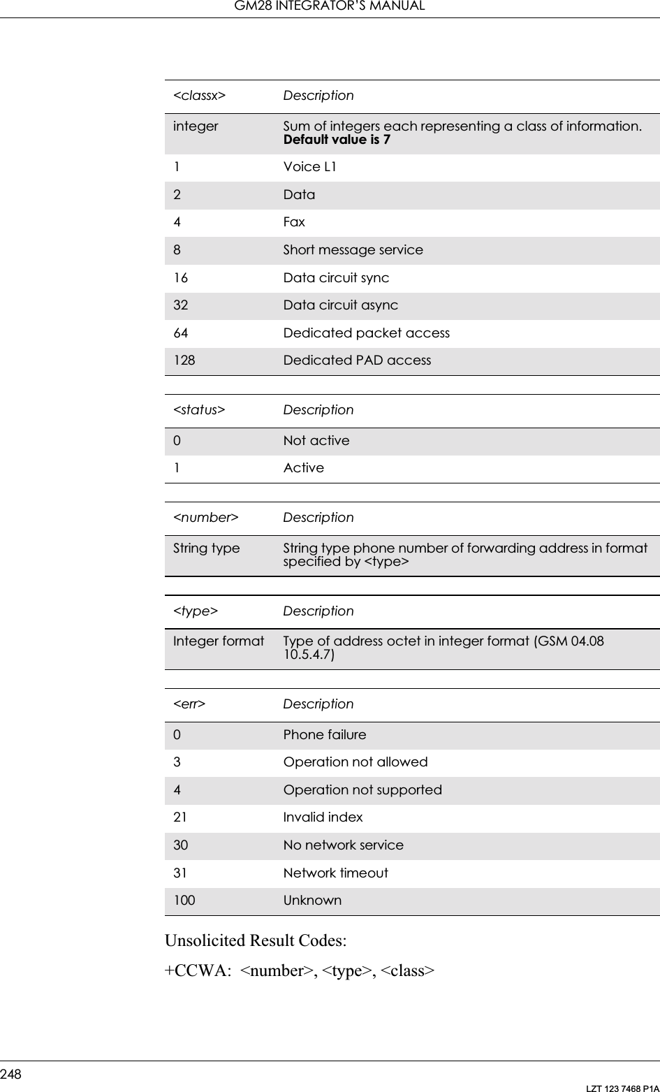
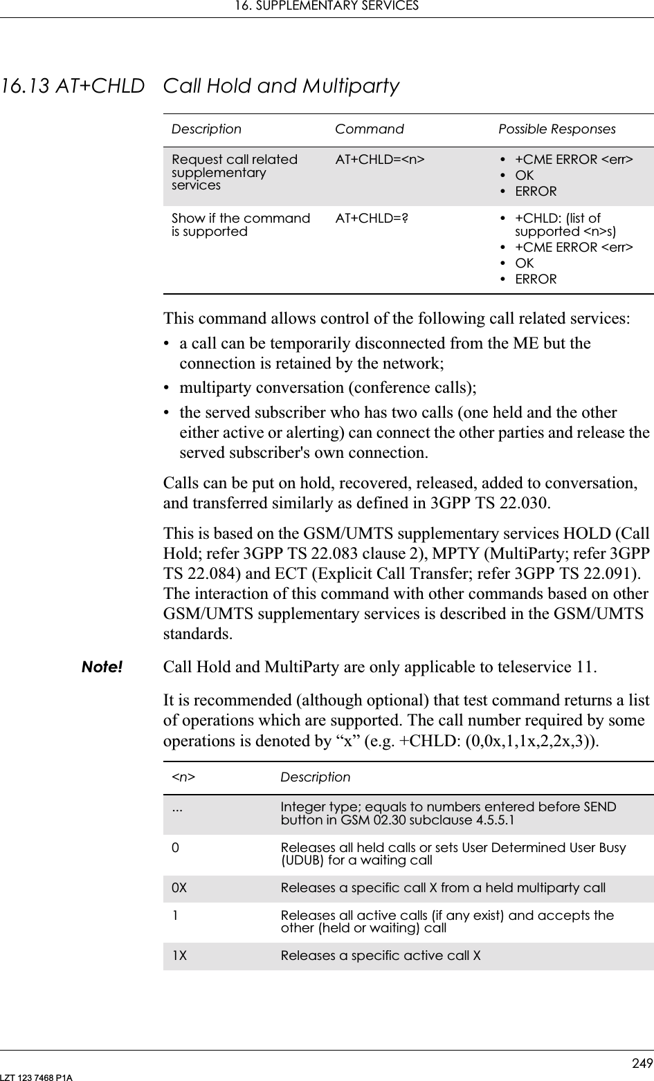
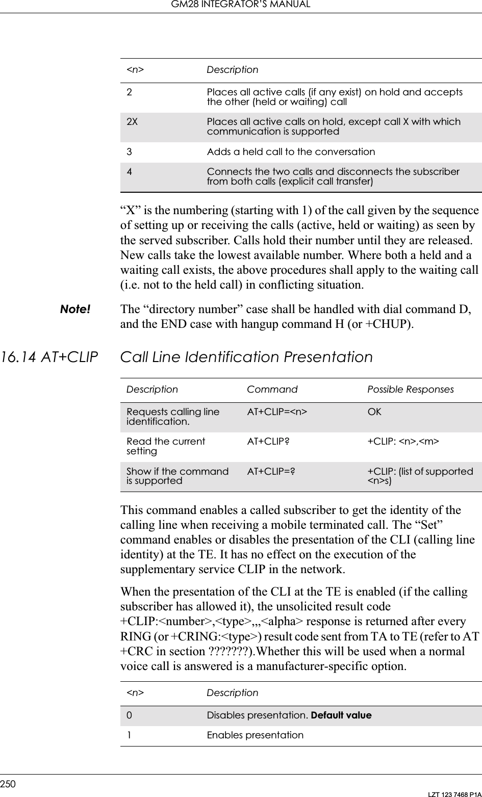
![16. SUPPLEMENTARY SERVICES251LZT 123 7468 P1AUnsolicited Result codes:+CLIP: <number>, <type>,,,<alpha>Defined values:16.15 AT+CLIR Calling Line Identification RestrictionThis command refers to CLIR-service according to GSM 02.81 that allows a calling subscriber to enable or disable the presentation of the CLI to the called party when originating a call.Set command overrides the CLIR subscription (default is restricted or allowed) when temporary mode is provisioned as a default adjustment for all following outgoing calls. Using the opposite command can <m> Description0CLIP not provisioned1 CLIP provisioned2Unknown (e.g. no network)<number> DescriptionString Type phone number of format specified by <type> type of address octet in integer format (refer to GSM 04.08, sub-clause 10.5.4.7)<type> Description129 129 ISDN/telephony numbering plan, national/international unknown145 145 ISDN/telephony numbering plan, international number161 161 ISDN/telephony numbering plan, national number128-255 Other values refer to GSM 04.08 section 10.5.4.7Description Command Possible ResponsesRequest calling line identification restrictionAT+CLIR=[<n>] • +CME ERROR <err>•OK•ERRORRead the current settingAT+CLIR? • +CLIR: <n>,<m>• +CME ERROR <err>•OK•ERRORTest if the command is supported AT+CLIR=? • +CLIR: (list of supported <n>s)• +CME ERROR <err>•OK•ERROR](https://usermanual.wiki/Sony/6220502-BV.Integrators-User-Manual/User-Guide-324170-Page-251.png)
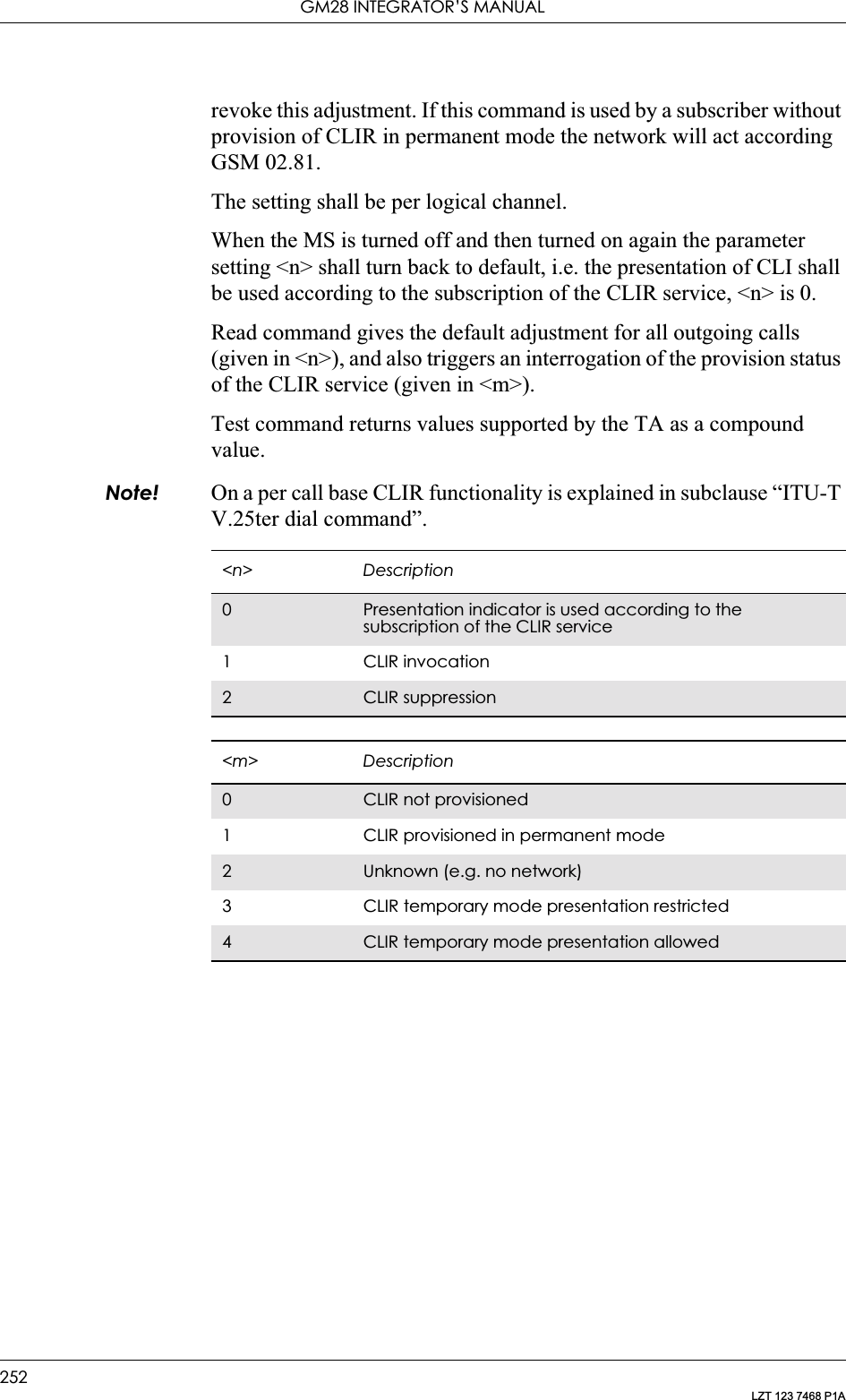
![16. SUPPLEMENTARY SERVICES253LZT 123 7468 P1A16.16 AT+CSSN Supplementary Service NotificationThis command refers to supplementary service related network initiated notifications. The set command enables or disables the presentation of notification result codes from TA to TE.When <n>=1 and a supplementary service notification is received after a mobile originated call setup, unsolicited result code +CSSI: <code1>[,<index>] is sent to TE before any other MO call setup result codes presented in this ETS or in V.25ter. When several different <code1>s are received from the network, each of them shall have its own +CSSI result code.When <m>=1 and a supplementary service notification is received during a mobile terminated call setup or during a call, or when a forward check supplementary service notification is received, unsolicited result code +CSSU: <code2>[,<index>] is sent to TE. In case of MT call setup, result code is sent after every +CLIP result code (refer command “Calling line identification presentation +CLIP”) and when several different <code2>s are received from the network, each of them shall have its own +CSSU result code.Note! The difference between <index> and <cindex> is that <index> is a position mark while <cindex> is a unique value for each CUG. <index> is not supported.Test command returns values supported by the TA as a compound value.Description Command Possible ResponsesPresentation of notification result codes from TA to TEAT+CSSN=[<n>[,<m>]] • +CME ERROR <err>•OK•ERRORRead the current settingAT+CSSN? • +CSSN: <n>,<m>• +CME ERROR <err>•OK•ERRORTest if the command is supportedAT+CSSN=? • +CSSN: (list of supported <n>s),(list of supported <m>s)• +CME ERROR <err>•OK•ERROR<n> Description0Disable the +CSSI result code presentation status in the TA1 Enable the +CSSI result code presentation status in the TA](https://usermanual.wiki/Sony/6220502-BV.Integrators-User-Manual/User-Guide-324170-Page-253.png)
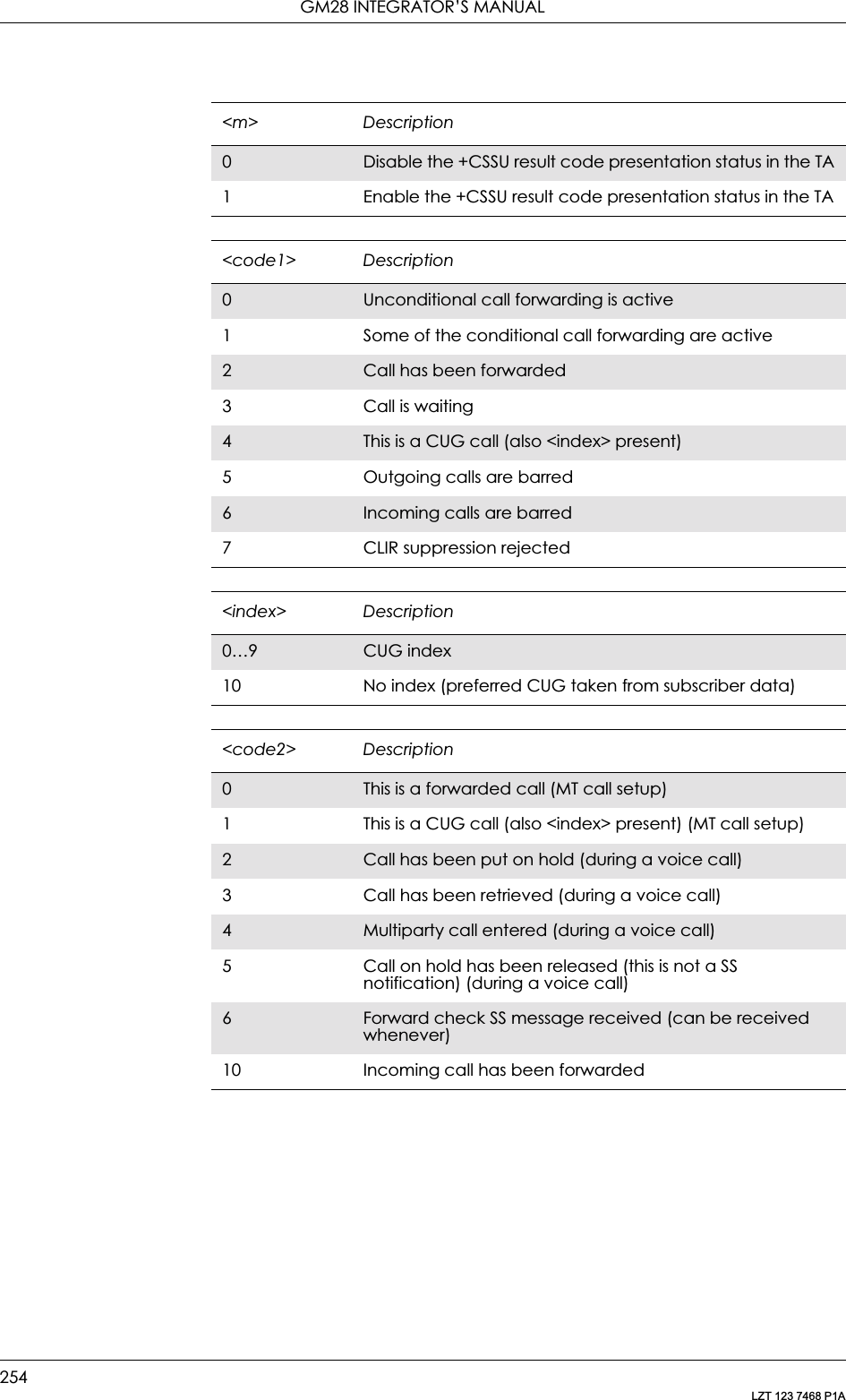
![16. SUPPLEMENTARY SERVICES255LZT 123 7468 P1A16.17 AT+CUSD Unstructured Supplementary Service DataThis command allows control of the Unstructured Supplementary Service Data (USSD) according to GSM 02.90. Both network and mobile initiated operations are supported. Parameter <n> is used to disable/enable the presentation of an unsolicited result code (USSD response from the network, or network initiated operation) +CUSD: <m>[,<str>,<dcs>] to the TE. In addition, value <n>=2 is used to cancel an ongoing USSD session. If <n> is not given then the default value 0 is taken.When <str> is given, a mobile initiated USSD string or a response USSD string to a network initiated operation is sent to the network. The response USSD string from the network is returned in a subsequent unsolicited +CUSD: result code.The interaction of this command with other commands based on other GSM supplementary services is described in the GSM standard.Test command returns values supported by the TA as a compound value.Some different scenarios are shown below:• An incoming network initiated USSD-Notify should be presented to the external application as an unsolicited result code +CUSD: if the external application has enabled result code presentation.• An incoming USSD-request asking for a reply should sent to the external application as an unsolicited result code +CUSD: if the external application has enabled result code.• If the external application answers to the request with the command AT+CUSD then the ME sends the answer to the network.• A USSD-request sent with the command AT+CUSD from the external application.Description Command Possible ResponsesRequest unstructured supplementary service dataAT+CUSD=[<n>[,<str>]] • +CME ERROR: <err>•OKShow supported message types along with the current service settingAT+CUSD? • +CUSD: <n>•OK•ERRORShow list of supported servicesAT+CUSD=? • +CUSD: (list of supported <n>s)•OK•ERROR](https://usermanual.wiki/Sony/6220502-BV.Integrators-User-Manual/User-Guide-324170-Page-255.png)