Sony Automobile Battery Charger User Manual To The 72320e91 9dde 483b 9c1a 07b446bd2830
User Manual: Sony Automobile Battery Charger to the manual
Open the PDF directly: View PDF ![]() .
.
Page Count: 17

READ THESE INSTRUCTIONS THOROUGHLY!
Follow the instructions STEP-BY-STEP, and your
installation will be trouble free. If in doubt, CALL
1-888-888-4079. We suggest that as you pro-
ceed through the installation, you should read a
few steps ahead in the instructions so you are
certain to catch all notes and warnings.
ATTENTION SUPERCHARGER INSTALLER!
Before proceeding with the installation, it is
important to know that to validate the 2 year,
100K warranty on your new J/R supercharger,
you must completely fill out the Moss Motors /
Jackson Racing warranty card that comes in
every kit, including serial number which is on a
small white ‘bar code’ label on the body of the
supercharger. Write down all of the numbers
which appear on that label in the appropriate
space on the warranty card. Be certain to do this
now because once your supercharger is
installed, it may be almost impossible to retrieve
that serial number.
SPECIAL NOTE: Jackson Racing Supercharger
Systems are designed to be installed by individu-
als with good mechanical sense and with the
proper tools. Use your discretion--if you are not a
competent mechanic, do not attempt this installa-
tion.
TOOLS REQUIRED: Most of these tools are
available at your local hardware or auto parts
stores.
17mm, 14mm, 13mm, 12mm, 10mm & 8mm
sockets
Deep sockets (14mm or 9/16”, 10mm)
Phillips and Standard screwdriver
Multi-purpose pliers
10mm, 12mm, and 17mm open end wrench
Timing light
A shop manual is useful.
WARNING: Once the installation is complete,
CHECK AND RECHECK ALL fuel system con-
nections for possible leaks before operating the
vehicle. 91-octane gasoline (or higher) is
required when running a supercharger.
During this installation process, you will reuse
some parts or hardware and not reinstall others.
It is recommended that you make space for
those that you will reuse, and a separate space
for those that you will not reinstall. In addition,
you should save the parts that will not get reused
in case you ever have reason to convert the
engine back to stock.
Enclosed is a set of labels that we suggest you
use to label the electrical connectors that you will
be unplugging.
Installation Instructions
SUPERCHARGER
with PowerCard
‘90-’93 Mazda Miata
Part# 999-156, 999-157, 999-158, 999-159
440 Rutherford St. P.O. Box 847 Goleta, CA 93117
1-888-888-4079 • FAX 805-692-2523 • www.supercharger.com
999-156 -1- Revised 1/07
1.0 DISASSEMBLY
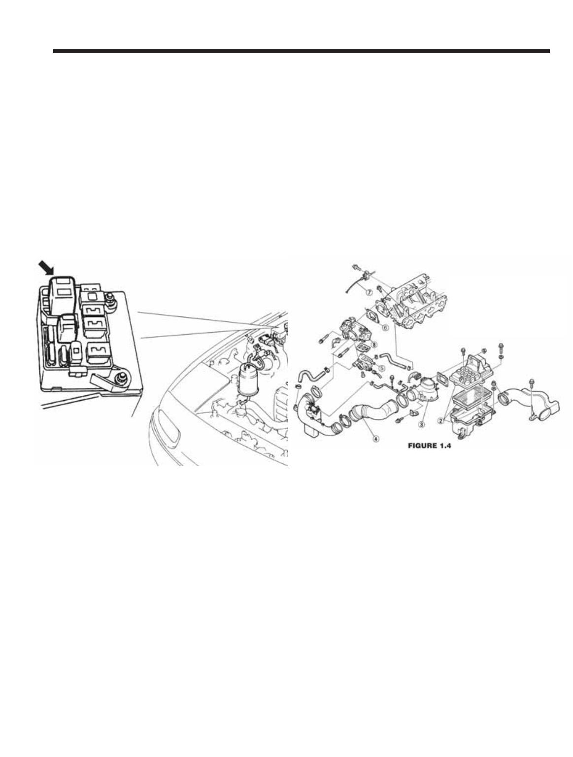
1.1 With the engine running, raise the hood and
locate the main under hood fuse box by the fend-
er well near the firewall on the passenger side of
the engine compartment. Lift the main fuse box
cover and locate the relay labeled “FUEL INJ”.
While the engine is running, remove the “FUEL
INJ” relay. The engine will stop running. Turn
your ignition key off. Store the “FUEL INJ” relay
in a safe place until you are finished with the
installation. Release the pressure in your fuel
tank by removing your gas cap momentarily and
then re-installing.
1.2 Release the airflow meter harness 7-pin con-
nector by lifting the small wire clip that runs
around the rectangular base of the connector.
Remove the stock air flow meter, air filter box and
intake snorkel. Remove the air flow meter from
the air box. Store the air box, filter, and snorkel
away. Move the air flow meter to a safe place on
a worktable.
1.3 Remove the molded rubber elbow and hard
plastic tube that lead from the throttle body to the
airflow meter. If you have cruise control, you will
also have to remove the vacuum line from the
intake manifold nipple and from the points where
it attaches to the hard plastic intake tube.
Remove the cruise control vacuum line from the
cruise actuator as well and save it for use in step
#4.4 later.
1.4 Remove the chrome crankcase vent pipe that
is attached to the front of the cam cover and the
rubber hose that leads into the cam cover
(Figure 1.4). These can be stored away.
However, find the small restrictor inside the rub-
ber hose that ran from the cam cover to the
chrome tubing. It can be felt as a lump in the
straight section of the hose near the chrome tube
end. Persuade it out by gently clamping the hose
with a pair of pliers just behind the “lump”. Save
this restrictor for step #7.8. Re-install the chrome
bolts that held the tubing in place. Store the
chrome tube and Mazda hoses away.
2.0 THROTTLE BODY
2.1 Remove the throttle body (Figure 1.4) by
releasing the two electrical connectors (one has
a spring wire, one has a plastic lever clip), the
two small coolant hoses on either side of the
lower Idle Control System (ICS) valve, and the
four bolts.
TIP: THE SPRING HOSE CLAMPS FROM
MAZDA ARE BEST REMOVED BY
APPROACHING FROM THE SIDE WITH NEE-
DLE NOSE PLIERS. GRASP ALL THREE
TANGS AT ONCE AND COMPRESS THEM
TOGETHER. THIS IS EASIER TO DO WITH
THE THROTTLE BODY ALREADY LOOSE
FROM THE INTAKE MANIFOLD.
999-156 -2- Revised 1/07
Supercharger Installation Instructions
2. Stock Air Filter Box
3. Air Flow
4. Stock Plastic / Rubber Cross Over
5. ICS Valve (Idle Air Control)
6. Throttle Body Gasket
7. Throttle Cable
8. Throttle Body
Keep the hose ends above the radiator cap
level to prevent leakage. Release the throttle
cable from the throttle shaft spool. Release the
Throttle Position Switch harness by lifting the
small wire clip that runs around the rectangular
base of the connector. If the throttle body gasket
tears as you remove it, you will need to clean
off the old gasket from both surfaces, the throt-
tle body and the intake manifold. Carefully use a
knife or the backside of a hacksaw blade to
scrape the mounting surfaces clean. DO NOT
SCRATCH OR MAR THE MOUNTING SUR-
FACES IN ANY WAY.
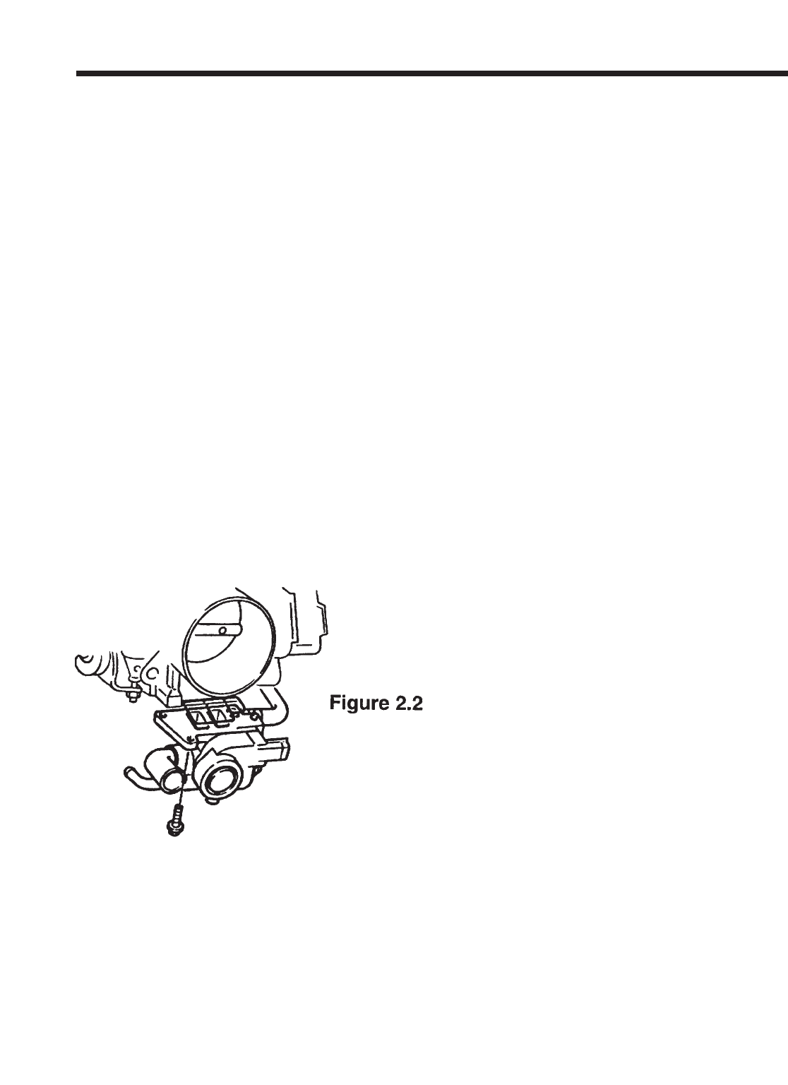
2.2 Moving to a worktable, remove the idle air
control (ICS) valve from the bottom of the throt-
tle body by removing the three Phillips head
screws. Use a good quality screwdriver and be
careful not to strip the Phillips head screws. If
you cannot loosen a screw with the screwdriver,
use a small set of pliers from the side. Carefully
separate the two units making sure not to tear
the rubber gland gasket. The rubber gland gas-
ket will want to stay with the Mazda throttle
body carefully pick it out with a flat blade screw-
driver and save it for the next step.
2.3 Take the Idle Air Manifold (dummy throttle
body) from your supercharger kit and install the
Mazda idle air control valve (ICS) from step 2.2
in the appropriate place. Use the rubber gland
gasket from the Mazda throttle body in this posi-
tion. Reuse the three Mazda Phillips screws.
Use no sealant, just the rubber gasket.
2.4 Install the Dummy Throttle Body and ICS
valve back onto the intake manifold in the same
position as the standard throttle body on the
intake manifold. Use the 1104 sealant provided
if the original gasket was not salvaged.
Reconnect the coolant hoses to the idle control
valve as you found them. Use hardware sup-
plied as necessary.
2.5 Reconnect the idle control valve electrical
connector.
2.6 Take the Throttle Position Switch (TPS)
extension wire (3 conductor with sheathing)
from your kit and use it to extend your factory
TPS harness. We have provided six heat shrink
butt crimp connectors to use for each wire junc-
tion you will first have to cut the three pin con-
nector off of the end of the Mazda TPS harness.
Cut at least 3 inches back from the end of the
plastic connector to give yourself enough room
to work with. Our extender has three color-
coded wires that match the colors of the Mazda
harness. Strip a small section from each wire’s
end on the harness extender and connect it to
the appropriate color wire. Use the heat shrink
butt connectors to secure each splice. Crimp
with an appropriate tool or pliers. Use a heat
gun or similar to shrink the butt connector’s pro-
tective tubing over the crimped connector. We
do not recommend the use of open flame to
shrink the tubing. Wrap the entire grouping of
three connectors with electrical tape at both
ends to protect from moisture and dirt.
2.7 Locate the ICS blanking plate and take it
over to your Mazda throttle body. You will use a
thin layer of sealant between the blanking plate
and the Mazda throttle body. Install this blanking
plate onto your Mazda throttle body using the
three Phillips head screws supplied in the kit.
Supercharger Installation Instructions
999-156 -3- Revised 1/07
3.0 BELT DRIVES
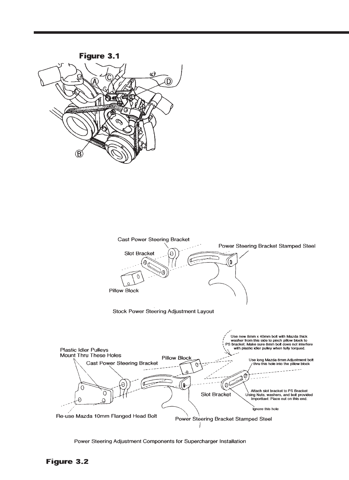
3.1 NOTE: CARS WITH POWER STEERING:
You will be rearranging your power steering
bracket components per figure 3.2. Referring to
figure 3.1, remove the slot bracket and pillow
block by removing bolts “A”, “C”, and “D”. Take
the flat idler pulley bracket from your kit and trial
fit it to the assembly per figure 3.2. You will be
moving the pillow block and bolt “D” to behind the
power steering stamped steel bracket. This
makes room for the flat idler pulley bracket. The
upper support for the repositioned long bolt “D”
comes from a relocated Mazda slot bracket. It
becomes an extension bracket for bolt “D”. The
slot bracket is attached to the stamped steel
power steering bracket using a new
bolt/washer/nut assembly supplied in your kit.
Make sure to point this bolt with its head nearest
the nylon idler pulley and that this bolt goes
through the slot. The forward hole of the reposi-
tioned slot bracket will not be used. The rearward
hole is now used for the relocated “D” bolt, which
will be used to tighten your drive belt. Note: The
power steering pump must be in its lowest posi-
tion for this procedure.
3.2 When you are done with your trial fitting of
the flat idler pulley bracket, take this flat bracket
to a workbench and install the two nylon idler pul-
leys using the spacers, bolts and nyloc nuts pro-
vided. Make sure that the bolts point toward the
front of the car.
Supercharger Installation Instructions
999-156 -4- Revised 1/07
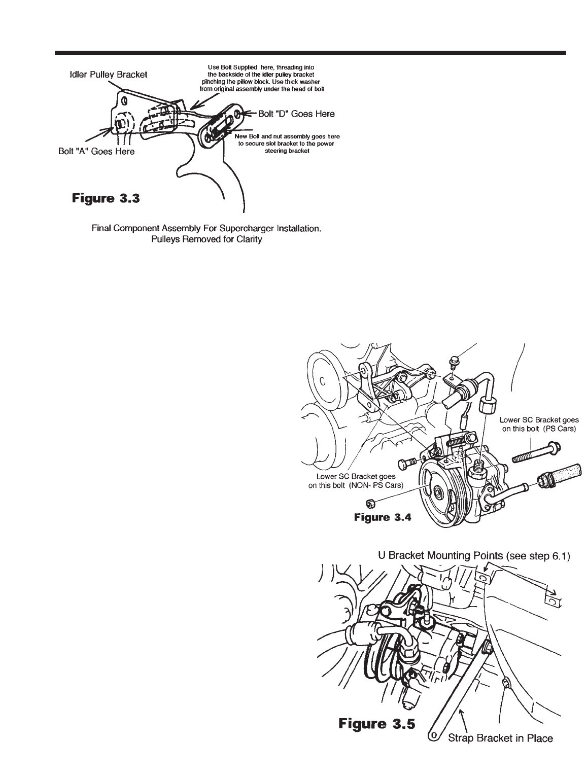
3.3 Secure the idler pulleys firmly to the flat brack-
et. Proceed to install the idler pulley assembly
onto the car per the procedure practiced during
the trial fitting. The final assembly (minus the pul-
leys) should look like figure 3.3.
VERY IMPORTANT: MAKE SURE THAT THE
DRIVER’S SIDE IDLER PULLEY IS FREE TO
SPIN. THE PINCH BOLT THAT YOU INSTALL
THROUGH THE PILLOW BLOCK FROM THE
REAR CAN INTERFERE WITH THE BACKSIDE
OF THE IDLER IF INSTALLED INCORRECTLY
(i.e. leaving out the thick washer under the bolt’s
head). TEST THE ASSEMBLY BY TIGHTENING
THE PINCH BOLT FULLY AND SPINNING THE
IDLER PULLEY. USE ADDITIONAL WASHERS
UNDER THE PINCH BOLT’S HEAD IF NECES-
SARY.
VERY IMPORTANT: Check the clearance
between the small coolant hose that runs from the
base of the thermostat housing and the passen-
ger side plastic idler pulley (see figure 8.1). If the
clearance is less than 1/2 inch between the hose
and the pulley, trim three quarters of an inch of
length off of the thermostat end of the small hose.
Reinstall the hose, reusing the spring clamp. By
removing a small piece of the hose end, the hose
will be pulled away from the idler pulley, avoiding
any damage during operation. This is a critical
area for attention since a hose failure could
cause severe engine damage. Not all cars need
this modification.
3.4 POWER STEERING CARS: Spin the power
steering pump pulley until the nut on the main
pump mounting bolt is visible. Insert a socket
wrench (deep 14mm) here and hold the rear hex
head with a 14mm box wrench. Remove the nut
and the long bolt (item “B” in figure 3.1). The bolt
will retract rearward underneath the exhaust
manifold.
3.5 Pick the flat steel supercharger bracket
from the kit and slip the long power steering
pump mounting bolt through the non-slotted
end. Reinstall the power steering pump bolt
and nut with the flat bracket pinched
between the bolt head and the cast power
steering pump bracket that is on the engine.
When finished, rotate the power steering
pump as far down as possible (the pulley
will touch the AC compressor pulley if so
equipped). This will allow room for the
supercharger to be installed and for the belt
to slip over the pulleys.
Supercharger Installation Instructions
999-156 -5- Revised 1/07
3.6 NON POWER STEERING CARS: Locate
your lower bracket assembly from the kit. The
end with the small 90-degree bracket mounts to
the idler bracket (standard on AC equipped cars)
or to new idler bracket (supplied with kit for non-
AC, non-PS cars). Use the new, longer 10mm
bolt provided to attach this bracket to the engine
(Review figure 3.4 for bolt location).
4.0 POWERCARD
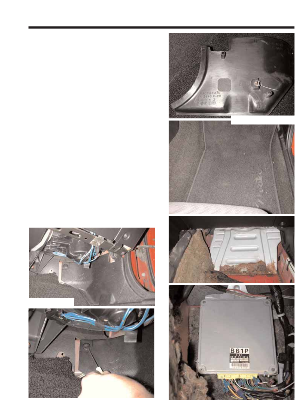
4.1 The Powercard will be installed in the pas-
senger (right hand) foot well. Remove the kick
panel trim by removing the plastic fastener
securing the top, front portion of the panel. Use a
small screwdriver to pull out the center section
and then pull the whole fastener out. There is
also a push in fastener in the center of the panel.
Slip your fingers up behind the panel and gently
pull out on the center until it pops free. Once the
center fastener is free, slide the panel out from
under the door sill trim and set it aside. Remove
the forward two screws from the door sill trim to
allow easy removal and reinstallation of the car-
pet. Remove the floor mat and pull back the car-
pet to expose a large metal plate. Using a 10mm
socket, remove the four nuts and one bolt that
secure the plate to the car. Remove the plate to
gain access to the Electronic Control Unit (ECU).
Supercharger Installation Instructions
999-156 -6- Revised 1/07
Illustration 4.1
Illustration 4.1 con’t
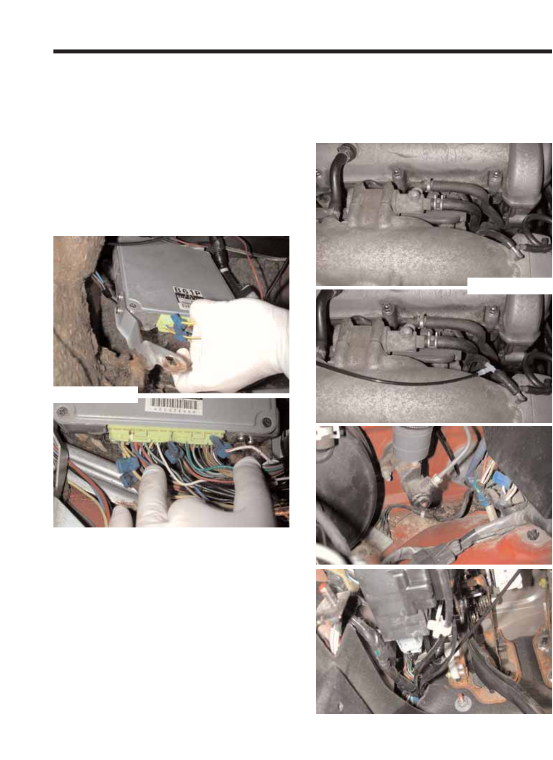
Illustration 4.1
4.2 Locate the fuel injector wires. They are a
large Yellow and a large Yellow/Black wire locat-
ed in the connector nearest the drivers side of
the car. Use the included T-taps and multi-pur-
pose pliers to tap into the wires. Next, locate a
large Black wire in the opposite end of that con-
nector. T-tap the Black wire. This is the system
ground. Now, in the far end of the other connec-
tor, locate the White/Red wire and tap into it.
This is switched battery positive. Connect the
Powercard’s Red wire to the T-tap on the
White/Red wire, the Black wire to the Black wire
at the ECU, and the remaining wires to either of
the injector wires. Illustration 4.2
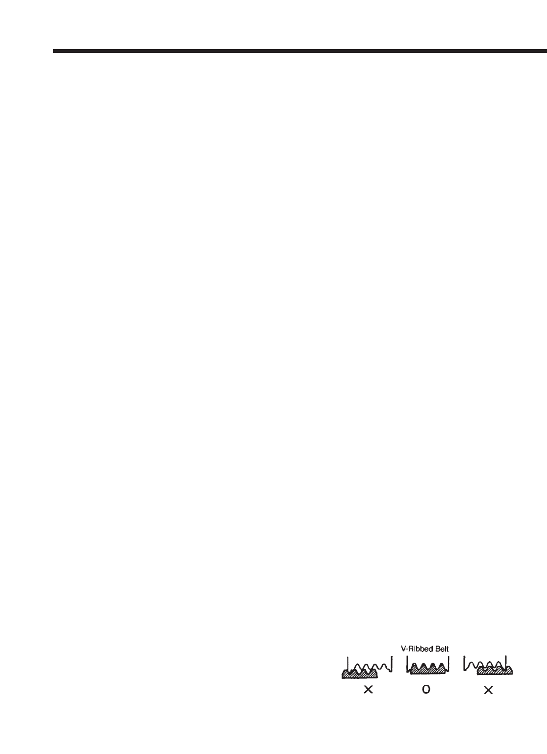
4.3 Route the vacuum source from the engine
compartment to the Powercard. Start under the
hood and locate a free vacuum port on the
intake manifold (right hand side of the engine).
If there are no free ports, splice into an existing
hose and use the included Tee to connect to the
hard plastic tubing included with the kit. Route
the tube from the intake manifold to the firewall
and across to the left side of the engine com-
partment. The tubing will go through the grom-
met with the wiring harness. Use a long phillips
screwdriver to push through the grommet. Be
cautious not to damage anything inside the car.
Remove the screwdriver and push a piece of
wire through the hole made by the screwdriver.
Wrap the wire around the tubing and secure
with electrical tape. Pull the tubing into the car
using the wire. Once inside the car, find a good
way to route the tubing across the car to the
Powercard location. Cut it to length if necessary
and connect it to the blue hose on the
Powercard. Illustration 4.3
Supercharger Installation Instructions
999-156 -7- Revised 1/07
Illustration 4.2
Illustration 4.3
4.4 The Powercard will mount to the underside of
the large metal plate. Find a location where the
Powercard can be without hitting the ECU. Make
sure both the metal plate and the back of the
Powercard are clean. Peal one half of the includ-
ed Velcro and attach it to the Powercard. Peal
the other half and attach it to the location picked.
4.5 Reinstall the plate, the carpet, the kick panel
trim and the two screws from door sill trim.
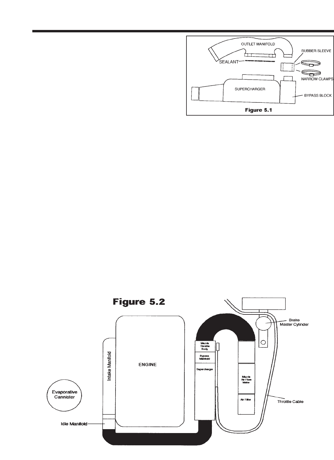
5.0 SUPERCHARGER PREPARATION
5.1 Working on a table, set the supercharger unit
in a position easy to work with. Be very careful
not to bump the supercharger pulley in any way
as it can easily damage the front bearing. Check
outlet manifold for debris and clean it out if nec-
essary. Install the outlet manifold as shown in fig-
ure 5.1. Get your Mazda throttle body with the
ICS blanking plate as installed in step #2.7 and
mount it to the supercharger using a thin film of
the sealant provided and the four bolts (8mm x
40) supplied in the kit.
5.2 Locate your throttle cable bracket that is bolt-
ed to your standard intake manifold and remove
the throttle cable by loosening the pinch nuts
surrounding the cable end on either side of the
bracket. Once the nuts are loose, you can pull
the cable out of the bracket - the grommet will
deform and let you do this. Remove the throttle
cable bracket by removing the two 10mm head-
ed
bolts. Unclip the throttle cable from the firewall
anchors. Begin rerouting the throttle cable by
looping the end behind the brake master cylinder
and laying it along the driver’s side fender well.
5.3 Locate the black plastic Roto-mold inlet elbow
from your kit. Check elbow for debris and clean it
out if necessary. You will be placing the assembly
into the position shown prior to installing the
supercharger. Make sure to install the 2.5” to
2.75” reducer hose to the airflow meter end of
this plastic elbow prior to setting it in place. This
will greatly assist in airflow meter installation.
Also, install the 2.5” diameter hump hose to the
throttle body end of this plastic elbow. Use the
Supercharger Installation Instructions
999-156 -8- Revised 1/07
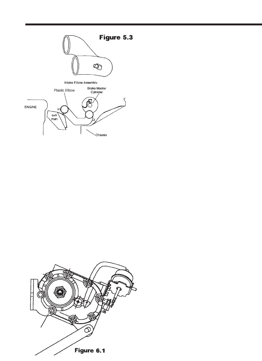
clamps provided to secure the hoses to the
elbow.
6.0 SUPERCHARGER INSTALLATION
6.1 Remove the engine lift eyelet at the front of
the engine, just above the exhaust manifold by
removing the bolt using a 14mm socket. Using
the two new flanged headed bolts supplied with
your kit, install these to the two bosses on the
side of your cylinder head. Leave at least 1/2” of
thread exposed on each bolt.
6.2 Bring the supercharger over to the engine.
Feed the throttle body end into the hump hose
already installed on the black plastic “air flow
meter to throttle body elbow” (make sure to slip a
fully opened hose clamp over the hose first).
Orient the supercharger so that you can slip the
large “keyholes” in the bracket attached to the
supercharger over the two bolt heads installed in
step #6.1. Make sure that the bolts move up their
respective vertical slots and seat against the
upper edge of the horizontal slots in the bracket.
Slide the supercharger towards the firewall as far
as it will go. Tighten down the two pinch bolts
using an open-end wrench. If you find that the
bracket/supercharger assembly collides with your
cam cover vent tube during initial installation, it
means you did not leave enough threads
exposed on the two main mounting bolts
installed in step #6.1. Retry it with the bolts fur-
ther out.
6.3 Swing the flat lower bracket up into place in
front of the supercharger boss. Locate the small
stamped throttle cable bracket from your kit and
thread the new bolt through the throttle cable
bracket hole, through the supercharger boss and
through the flat steel lower bracket. Secure with
the locking nut and bolt supplied. Make sure that
the head of the bolt is on the throttle bracket side
of the assembly. Leave the power steering pump
long bolt and nut finger tight (14mm heads).
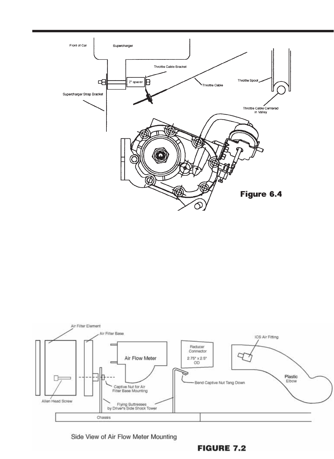
6.4 Route your throttle cable so that it is looped
back toward the firewall, routing the cable just
behind the driver’s side headlamp motor. Install
the cable’s threaded end into the small bracket
attached to the underside of the supercharger.
Make certain that the cable/grommet is fully
nested within the slot (this may require some
muscle - we made it tight so your throttle cable
won’t ever fall out). Open the throttle by hand and
insert the cable end into the throttle spool. Make
sure that the cable runs in the center of the
groove of the throttle spool. If it does not, adjust
the throttle cable bracket left or right until it is cen-
tered in the spool’s groove. Have an assistant
operate the gas pedal multiple times to confirm
that the action is free and easy without binding or
interference. Make sure that the cable has a bit of
“sloppy” slack with the gas pedal released and
that full throttle is available when the gas pedal is
fully depressed. If it does not “flop” in the idle posi-
tion, you will have trouble setting your idle speed.
Make sure that the cable is run in such a way as
to allow for engine movement from side to
side.Make very certain that all throttle cable-
mounting points are secure - this installation
area is critical for safe operation of your car.
This bracketry has been carefully designed for
correct operation. It is your responsibility as
the installer to ensure that it is bolted together
successfully without binding or interference.
Supercharger Installation Instructions
999-156 -9- Revised 1/07
7.0 AIRFLOW METER WORK
7.1 Locate the new air filter base from your kit and
install it to the air flow meter intake port, reusing the
Mazda cork gasket and four nuts. The air flow meter
is offset toward the top of the air filter base. The
seven pin electrical connector on the airflow meter
faces upward.
7.2 Locate the driver’s side shock tower support and
notice the Mazda air filter box mounting bracket
(painted body color) on the forward edge. This verti-
cal bracket is held in place by a horizontal bolt (also
painted body color). Remove the bolt using a 10mm
socket and store the bracket. On the “flying but-
tress” closest to the firewall, bend the captive nut
tang downward to make room for the plastic elbow
section using a small screwdriver in the hole.
Supercharger Installation Instructions
999-156 -10- Revised 1/07
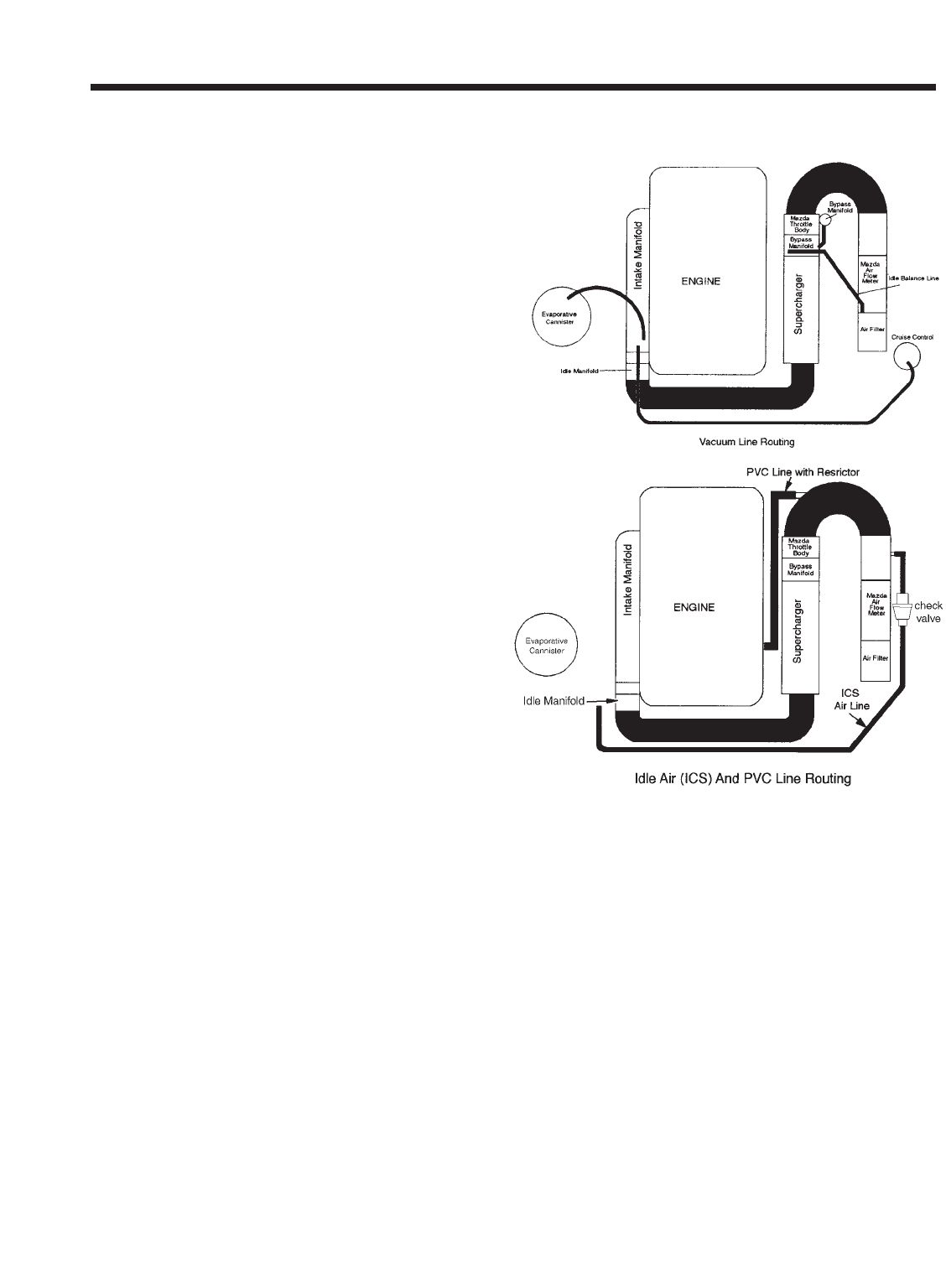
7.3 Bring the air flow meter with the air filter base
installed over to the engine bay. Tilting the assem-
bly at an angle, feed the air flow meter outlet into
the rubber reducer sleeve already in place on the
plastic elbow (install loose hose clamp first). The
air flow meter assembly fits into the space just
inside the shock tower, between the two “flying but-
tresses” of the shock tower. The extra hole and
boss in the air filter base will line up with the hori-
zontal hole you just removed the 6mm body col-
ored bolt from. Using the longer bolt provided (M6
x 30mm, Allen head), attach the air filter base/air
flow meter assembly to the car using this bolt (it
mounts horizontally, through the air filter base, the
flying buttress, and into the Mazda captive nut on
the flying buttress). Use thread-locking compound.
7.4 Make sure that there is no chaffing or rubbing
anywhere along the plastic elbow assembly, even
though it is a very tight fit. Gently reposition any
brake lines that are pressing against the elbow.
Make sure all joints and clamps are secure - a leak
in this area will keep your car from idling correctly.
However, never over tighten your clamps, they
may break somewhere down the road. Use the
small length of rubber hose (1/4” dia) that is slit
along its length to cover the brake line running just
above the elbow. This will prevent any contact at
this point, which may result in noise during opera-
tion.
7.5 Locate the 3/4” diameter idle air hose (5’
length) from your kit. Attach one end to the ‘large’
outside fitting on the plastic elbow downstream of
the airflow meter (just below the brake master
cylinder once the elbow is in place). Use a clamp
to secure the hose to the short 3/4” nipple. Run
the hose toward the front of the engine compart-
ment, and across the engine side of the radiator.
Using the tie wraps provided, attach the rubber
hose securely to the radiator fan shroud supports
near the fan motor(s). Attach the end of the hose
to the idle control (ICS) valve nipple that is aimed
toward the front of the vehicle. Make sure that the
hose is attached in a way that will not interfere with
either fan operation or with the engine belts. At a
point along the length of the hose behind the radia-
tor, cut it and install the check valve supplied.
Install the check valve with the flanged end toward
the plastic elbow using the small hose clamps. See
figure 7.6. The hose is supplied a bit longer than it
needs to be. Feel free to trim its length if you pre-
fer. Be careful not to pinch the hose at any point -
doing so will affect your idle stability. You want to
have it tie-off in a low position; the cross over tube
will fit above this hose, hiding it in the final installa-
tion. On some cars, there might be a slight kink in
the hose where it attaches to the plastic elbow nip-
ple. This is acceptable - orient the hose so it
remains open.
7.6 Install the air filter element over the air filter
base. Next, collect the two studs and install them
with the element in place. Install the waffle-pat-
terned air filter cap and secure using the nuts pro-
vided. Use the tie-wraps provided to secure all
components and keep them clear from the belt
runs, exhaust manifolds, and especially the throttle
cable. Reroute the air bag harness over the air fil-
ter, keeping it away from the headlight raising
motor. IMPORTANT! Secure the air bag harness
with tie wraps to keep it from falling into the
engine belt system or being pinched in any
way.
Supercharger Installation Instructions
999-156 -11- Revised 1/07
Figure 7.5
7.7 Take the throttle body wiring harness extension
as left in step #2.6 and route the body of the har-
ness along the firewall using the bright cad plated
firewall clips that originally held the throttle cable on
your stock Miata. Tie-wrap the extension harness
along the firewall in at least two places. Make sure
to leave enough slack on both ends to allow the
engine to rock side to side without pulling on the
harness. Contain any extra length in a neat fashion.
Connect the female end to the throttle body at the
throttle position sensor.
7.8 Find the internal restrictor taken out of your
PCV hose in step #1.4. Locate the 3/8” internal
diameter rubber hose from your kit and press the
restrictor into this hose at least one inch. Attach this
hose from the ‘medium’ size fitting on the plastic
intake elbow (near the throttle body, pointing to the
engine). Cut to length and attach the other end to
the camshaft cover fitting on the exhaust side.
Make sure the hose does not kink at any point and
that the restrictor is not left out. If you leave the
small restrictor out, the engine will not idle correctly.
7.9 Locate the 5/32” internal diameter idle balance
hose and attach it to the ‘small’ fitting on the plastic
elbow. Attach the other end to the unused vertical
vacuum nipple on the bypass block of the super-
charger. Cut the line to the proper length, leaving
some slack to allow for engine movement. Make
sure the line is not pinched in any way and that it
has no possibility of interfering with the throttle
cable or spool. Use tie wraps as necessary to
secure the line. The diagram in figure #7.5 shows
the bypass actuator signal line being attached to
the engine side nipple on the bypass manifold. It
may be connected to the fender side nipple –either
is acceptable. Connect your idle balance line to
whichever vertical nipple is unused. The bypass
actuator may have two nipples on its “can”. The
upper one is used in this kit. The lower nipple
should be left open - it is used in the GM factory
installations.
7.10 Reconnect the 7 pin electrical connector to the
air flow meter. Make sure the harness is not
pinched at any point.
8.0 FINAL ASSEMBLY
8.1 Install the new 4-rib drive belt. This new belt will
run counter-clockwise from the crankshaft, around
the air conditioning compressor, up to the power
steering pump, over to the right nylon idler pulley,
up and over the supercharger pulley, just under the
left nylon idler pulley, and back down to the crank-
shaft. Figure 8.1 shows the belt run for configura-
tions A-D listed below. If you find the belt to fit too
tightly, gently rock the car in fourth gear while
pressing the belt onto the pulley using the following
trick. Put the belt on all pulleys EXCEPT the super-
charger pulley, which you should leave for last.
Feed the belt onto the supercharger pulley in a
COUNTERCLOCKWISE direction; place the car in
fourth gear with the handbrake off (and the ignition
keys OUT!). Gently roll the car backwards with your
body weight while insuring that the belt feeds itself
onto the supercharger pulley the last little bit. Watch
out for your fingers. Make sure the belt does not roll
off of either inside idler pulley while it feeds onto the
supercharger pulley.
UNDER NO CIRCUMSTANCES SHOULD YOU
USE THE ENGINE STARTER TO “BUMP’ THE
BELT ONTO THE SUPERCHARGER. DOING SO
PUTS A HIGH LOAD ON THE SUPERCHARGER
BEARING AND WILL VOID YOUR WARRANTY.
ALSO, IT IS VERY DANGEROUS.
Loosen the pinch bolts on your relocated power
steering adjustment assembly (12mm head on pil-
low block pinch bolt, 14mm head on lower front
bolt). Tighten the long bolt “D” per figure 3.4 to
achieve correct belt tension. The longest run of the
belt should not deflect more than 1/2” when
pressed down with around 22 pounds of thumb
pressure. The tension specification is 90 pounds.
An easy check for proper belt tension is done by
listening to your belts during warm up. If turning the
steering wheel with the air conditioning creates a
squeal, then the tension is too loose. In general,
only a slight amount of black dust should appear
around the supercharger nose when the tension is
correct. Heavy dusting indicates excessive belt
wear from a loose belt. Check your tension again
999-156 -12- Revised 1/07
Supercharger Installation Instructions

after the first 500 miles - it will loosen slightly as the
belt wears in.
NEVER ATTEMPT TO ADJUST THE BELT WITH
THE ENGINE RUNNING! Retighten all bolts and
double-check your work.
8.2 Locate the rubber sleeves and the front cross
over tube. Check the inside of the cross over tube
for debris - clean if necessary. Running a rag
through the pipe pulled by a strong wire is a good
way to do this. Install the cross over tube between
the idle air manifold (dummy throttle body now on
the intake manifold) and the supercharger dis-
charge manifold. If you find the rubber sleeves
hard to slip over their respective landings, use
some spray light oil such as WD40, which dries off
to lubricate the situation. Do not use gasoline prod-
ucts or pure silicone products. The best technique
for installing the cross over tube involves putting
the 2.75” diameter rubber sleeve on the super-
charger manifold and the 2.5” diameter sleeve on
the cross over tube, and attach both with clamps.
Then install the cross over tube, starting at the
supercharger end first.
8.3 If you have cruise control, route the factory
vacuum line from the cruise control back to its orig-
inal position, being careful to tie-wrap it away from
the engine belts or radiator fans. Remove the steel
spacer from one of the mounting grommets on
your stock Mazda air box. Use this 13/16” long
spacer and the 6mm x 25mm hex head bolt sup-
plied to secure your cruise control brace to the air
filter base. The bolt will go vertically through the
cruise control leg brace and into the small ledge
with a threaded hole on the air filter base.
8.4 Once the cross over tube is installed correctly,
double-check all your pipe and tube connections.
There should be no loose ends or connections. Do
not over tighten any hose clamps, but ensure that
they are snug. Double check your supercharger
belt for correct tension. If the cross over tube is
pressing too hard against your upper radiator
hose, you can remove 3/4” to 1” from the radiator
end of the hose to allow for more clearance, if you
wish. You are now ready to start your engine.
8.5 First, crank your engine for a few seconds with
the “FUEL INJ” relay still removed from step 1.1.
Confirm that the supercharger belt stays on and
that no other parts have been left unattended to.
8.6 Reinstall the “FUEL INJ” relay. Complete step
8.7 before starting your engine.
8.7 CLEARANCES
IMPORTANT! MAKE SURE THAT YOU HAVE AT
LEAST 3/4” INCH CLEARANCE BETWEEN ANY
ENGINE MOUNTED COMPONENT AND ANY
BODY MOUNTED COMPONENT. CRITICAL
AREAS: BYPASS ACTUATOR TO BRAKE LINES
(VERY CRITICAL - The engine “rocks” strongly to
the driver’s side upon deceleration. If clearance is
too tight, your brake lines can be gently deformed
away from the super-charger bypass actuator by
hand. ) SUPERCHARGER OUTLET MANIFOLD
TO AIR FILTER (INCLUDING CLAMPS) ALL VAC-
UUM LINES TO THROTTLE SPOOL AND CABLE
8.8 For trouble shooting and testing the PowerCard
prior to driving, follow these procedures. Unscrew
and remove the back of the PowerCard. You will
see 3 LED lights in a row. The Green, Yellow, and
Red lights are fuel enrichment lights and MIL
(Malfunction Indicator Lights) lights. Read the lights
and refer to the following to find the source of the
MIL problem.
If the box has been wired for power and ground cor-
rectly you will see the Green light is illuminated and
flashing with the ignition switch in the “On” position
and the engine off. Start the car and check that the
Green light is illuminated continuously and not flash-
ing. There should be no other lights illuminated. If
you have no lights when you power up the vehicle,
you either have a power (Red wire) or ground
(Black wire) problem. Double check your connec-
tions at these two wires until they test properly.
If the Green light is flashing after the vehicle is
started, the Blue wire is not connected to a fuel
injector wire or the connection is not complete. If
the Yellow light is flashing, one of the Gray wires
has a bad connection or is not connected to an
injector wire. The Yellow MIL light will not function if
the Green light is also flashing. In this case you
must fix the Blue wire problem first.
Inside the box is one more LED located away from
the other three LED’s. This is your “Boost
999-156 -13- Revised 1/07
Supercharger Installation Instructions
Activation” LED. Once the engine is warmed up,
push the throttle hard so that the engine gains RPM
quickly (creates boost) and then let it come back to
an idle. During this process, this LED should
become illuminated temporarily. It only comes on
when the pressure transducer in the box reads
boost from the engine.
9.0 ENGINE ADJUSTMENTS
9.1 SUPERCHARGER BELT DRIVE ADJUSTMENT
Start your engine and observe your belt drive. The
belt should line up with itself as it passes between
the two nylon idlers. To put it a different way, the
portion of the belt running up to the supercharger
should lay almost directly over the portion leaving
the supercharger and heading toward the power
steering pulley. If the upward run is more forward or
rearward than the downward run, you need to
move your supercharger slightly forward or back-
ward with respect to the crankshaft pulley. You can
now access the two bolts attaching the supercharg-
er’s bracket to the cylinder head from step 6.1 with
an open-end wrench. Loosen each bolt slightly to
allow for adjustment. Start the engine. You can now
move the supercharger assembly slightly forward or
rearward to correctly align the drive pulleys. The
slots in the Supercharger mounting bracket will
allow you to find the perfect alignment for the belt
run. NOTE: Do not attempt to move the super-
charger with your hands with the engine run-
ning. Use an appropriate tool. The best tool to
use is a flat blade screwdriver placed between the
forward bracket bolt and the front inside edge of the
bracket. Move the supercharger assembly while
watching the belt run the idler pulley. If you have
the two bracket bolts too loose, the supercharger
will be out of alignment from side to side. Make
sure the two bolts are snug enough to just allow
some leveraged movement. Once you have the
belt running true in the center of the idler pulleys,
tighten the rear bolt to secure the position. Shut off
the engine and tighten the other bracket bolt
securely. Recheck all mounting bolts for tightness.
9.2 IDLE ADJUSTMENT:
Restart your engine. Using the idle airscrew on
your throttle body (now on the back of the super-
charger), adjust your idle speed to 950-rpm after
the engine is warm. This can best be approximat-
ed by closing the screw completely (turning clock-
wise) and backing it out one and a half turns
counter-clockwise. Adjust further to reach the
950-rpm value. Next, turn your headlights on
BRIGHT and put your heater fan on HIGH. Leave
the air conditioning off. Rev the engine briskly in
neutral to at least 2500 rpm and release. Notice if
the idle stops at 900 rpm. If it dips below this
level and feels like it will stall, then recovers to
950 rpm, open the idle airscrew (counterclock-
wise rotation) one tenth of a turn at a time until
most of this “droop” disappears. A slight droop of
100 rpm or so is acceptable and normal. More
than that may create a stalling problem during
driving. Turn off the lights and heater fan and
double check that your idle speed is 950 rpm. If
you open the idle screw too much, you will create
too high of an idle speed when the lights and fan
are turned off. You also may possibly introduce a
stumble on part throttle to full throttle accelera-
tions. In addition, a slow return to idle behavior
will occur.
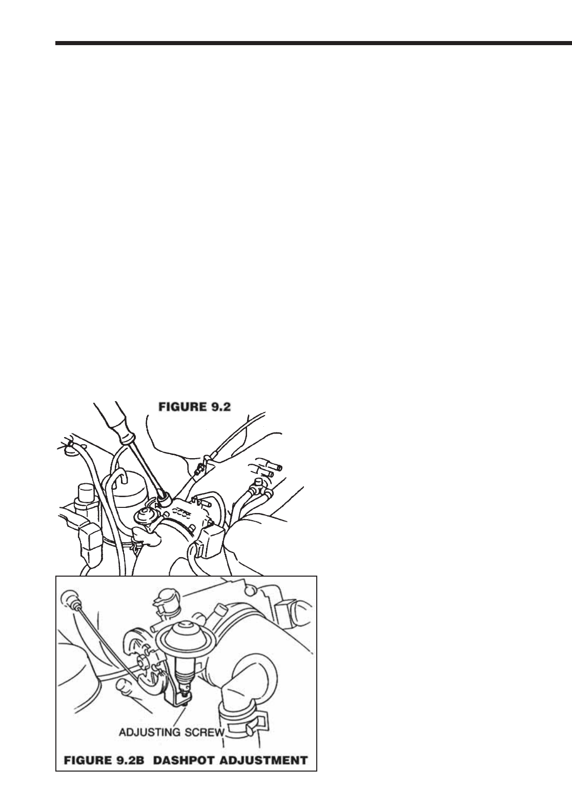
9.3 If you have difficulty stabilizing the drooping
idle problem, adjust your dashpot to help in slow-
ing the throttle’s closing. The factory specification
is that the dashpot tip just begins to touch the
throttle arm at 2500 rpm. Have an assistant hold
the engine at 2500 rpm from the driver’s seat.
Supercharger Installation Instructions
999-156 -14- Revised 1/07
The dashpot tip should just be touching the throt-
tle arm. Adjust the dashpot so that this contact
point is at 3000 rpm or more to help with the
drooping idle. Your Miata will drive best with the
lowest idle speed possible with only a slight
droop in the idle (checked as described above
with a warm engine, lights and heater fan on
high).
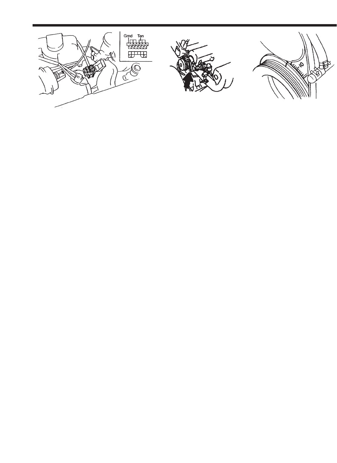
9.4 Using a timing light, adjust your ignition tim-
ing to 6 degrees before top dead center (BTDC).
You have to run a jumper wire (an unfolded
paper clip will do nicely) between terminals
“GND” and “TEN” of your diagnostics center
(located just above the driver’s side shock
absorber). The ignition timing is adjusted using
the position sensor mounted at the firewall end
of the intake camshaft. A 12mm box wrench will
loosen the securing bolt.
9.5 IGNITION TIMING AND FUEL QUALITY: Your
Miata supercharger kit is designed to operate on 91
Octane fuel. Make sure that you run your engine on
91 octane only, which means you should complete-
ly burn up any lower octane gas in your tank and
refill it with 91 octane before installing your super-
charger kit. NOTE: In any case, should you ever
hear “pinging” or knocking from your engine
when under acceleration, you should take
measures to eliminate this detonation, i.e. high-
er-octane fuel or a further retardation in ignition
timing. NEVER CONTINUE TO OPERATE YOUR
ENGINE IF YOU HEAR ANY SIGNS OF DETO-
NATION (PINGING OR KNOCKING).
This kit has been carefully designed to work within
the stock Mazda engine parameters and no deto-
nation will occur if the above settings and fuel are
followed. The only way detonation can creep into
your situation is if your engine has a mechanical
fault, the fuel you are using is of the incorrect
octane, if your timing is set incorrectly or if your
fuel filter is clogged. It is your responsibility as the
installer of this kit to ensure that the supercharger
has been installed according to specification.
DRIVING TIP:
If you should find yourself in a situation where you
cannot find high-octane fuel, you can bypass the
supercharger temporarily. Note the position the
bypass actuator arm is in during idle. This is the
position that bypasses the boost air back into the
supercharger inlet. As you blip the throttle, the
actuator arm will move and close a butterfly valve
inside the bypass manifold. Using a short piece of
wire, fix the bypass actuator arm in the “bypass”
position that it holds at idle. This will prevent boost
from being developed and thus, detonation will not
occur. Of course, your engine will now run like a
stock Miata, but will be quite operable for as long
as you need. When you find higher-octane fuel,
simply remove the wire to release the actuator arm
and the bypass will function normally, closing dur-
ing acceleration, bypassing during idle and cruise.
Try to run the low octane fuel out of your tank
before filling up. Mixing fuels of different octane will
lower the overall rating and detonation could still
be a problem. You can order a Jackson Racing
Boost Timing Controller that retards your tim-
ing during boosted conditions. This is useful
for those who can only find 91 Octane fuel or
wish to increase their low-end power by
advancing the static ignition timing.
9.6 Starting procedure: Start your engine as you
would a standard Miata. Remember to bring the
engine up to operating temperature (as indicated
by your water temperature gauge) before running it
hard. Full boost on a cold engine will greatly
increase your engine wear.
9.7 Oil changes: we suggest you use synthetic oil
such as Mobil 1 and change it regularly (5000
miles maximum). If you use a mineral oil, change it
every 2500 miles. While your supercharger does
not use any engine oil for its lubrication, your
engine will be working a little harder with the addi-
tion of a supercharger. The synthetic oil provides
an extra measure of protection, but is not neces-
sary for safe and reliable operation.
9.8 Breaking-in: Your supercharger will work per-
fectly from the first time you fire it up. However, it
does need about 500 miles to fully seat the rotors.
Up to that time, you may notice a slight noise com-
Supercharger Installation Instructions
999-156 -15- Revised 1/07
Figure 9.4

ing from the supercharger at idle. This is normal.
9.9 Performance: You will notice that your engine
runs stronger on cold days than on very hot ones.
This is due to the nature of the internal combustion
engine. When the air is cold, the engine receives a
denser charge of air, thus more power can be pro-
duced. While this is true with any engine, the
supercharger amplifies this cold air benefit.
10.0 LONG TERM MAINTENANCE
10.1 BELTS
The only item to watch with your supercharger kit
will be the belt tension for the supercharger drive.
If you have a tension gauge for a poly-vee belt, the
tension is to be 90 pounds. If you see a large
accumulation of belt dust on your supercharger, it
is an indication that your belt is slipping. A slight
amount of belt dust is normal. CHECKING YOUR
BELT FOR WEAR: As the belt wears, small
cracks will form in each of the ribs on the inside
run of the belt. Replace your belt when you can
count six cracks within in one inch of length (six
cracks total from all ribs combined).
10.2 DRIVEABILITY
If you notice a driveabilty problem as your car
ages, have your fuel pressure checked. Have a
technician install an accurate 0 to100psi fuel
pressure gauge in the fuel line BEFORE it enters
the fuel rail .
10.3 Every six months or so, check your hose
clamps for correct tension. The rubber hoses will
take a set and the clamps may not be holding as
tight. Also check all mounting bolts and nuts, par-
ticularly the throttle cable anchor bracket.
10.4 Your air filter is a long-life unit needing serv-
ice only every 15,000 miles. To clean, you can
wash the filter element in soap and water. Use a
dish detergent soap such as Dawn, etc. Rinse
thoroughly and allow to dry. Wet the filter element
with a light application of ATF (automatic trans-
mission fluid). Alternatively, a special cleaning kit
is available from Jackson Racing (#901-970).
10.5 At every oil change, lubricate the bypass
actuator arm contact point and shaft bushing with
light grease to insure long life - these parts are
exposed to under hood dirt and grime.
TROUBLESHOOTING
SYMPTOM: Engine cranks but will not start
PROBABLE CAUSES: Airflow meter disconnect-
ed; Idle air line open; Low battery voltage
CURE: Double check that seven pin to airflow
meter is well connected. Re-check the 3/4” ICS
line and the PCV line to see that they are not
leaking. Use a known good battery to “jump” the
Miata’s battery. It is possible to have enough volt-
age to crank a Miata but not enough to correctly
run the engine’s control computer.
SYMPTOM: Unstable Idle
PROBABLE CAUSE: Idle air screw set incorrect-
ly; Restrictor left out in step #7.8; Pinched idle air
balance line; air leak in intake track.
CURE: Re-check restrictor. Check idle adjustment
procedure in step 8.1 above. Check the idle air
balance line for restriction or pinching. Check for
air leaks - vacuum at idle should be at least 17.7
in Hg.
11.0 FURTHER MODIFICATIONS
Now that your Miata has a stronger engine, there
are a few changes you might want to make to the
rest of the car to improve its performance. The fol-
lowing are not required for your supercharged
Miata, but are presented as tuning hints for a bet-
ter all-around car.
We recommend that you install a Jackson Racing
Stage 1 clutch when it comes time to put in a new
clutch. While your new supercharger and the stan-
dard Mazda clutch work well together, it is a good
idea to step up to the Jackson Racing unit when
you are changing your clutch.
We recommend you install a set of Jackson
Racing larger diameter anti-roll bars for the sus-
pension for your Miata. These will tighten up your
steering response. We also recommend a new set
of Tokico shock absorbers if your Miata has over
30,000 miles on it. The Tokico shocks coupled
with a set of the Sport lowing springs will lower the
car about 35mm. This combination yields better
handling with out the harsh ride of competition
springs. Have your car aligned afterward (driver’s
equivalent weight in the driver’s seat) to factory
specifications after any suspension changes.
You might want to add a Jackson Racing Boost
Supercharger Installation Instructions
999-156 -16- Revised 1/07

and A/F ratio gauge to your supercharged Miata.
These are good for keeping an eye on things. A
performance exhaust will make your super-
charged Miata that much faster. Since you are
now flowing 300 cubic feet per minute through a
muffler designed for 177cfm, an improvement
can be made. Jackson Racing offers a Stainless
Steel Cat-back exhaust system designed around
the Supercharger.
WARRANTY: The supercharger system carries a
two-year or 100,000 mile warranty (for the origi-
nal purchaser of the kit) against defects in materi-
als and workmanship. No other warranties apply.
This warranty is void if the subject vehicle is used
in any racing activities of any sort.
HELP: If you experience any problems with your
kit during installation or operation, contact your
retailer or Jackson Racing at 1-888-888-4079.
Supercharger Installation Instructions
999-156 -17- Revised 1/07
