Sony HT DDW670 User Manual HOME THEATRE SYSTEM Manuals And Guides L0522693
SONY Home Theatre Manual L0522693 SONY Home Theatre Owner's Manual, SONY Home Theatre installation guides
User Manual: Sony HT-DDW670 HT-DDW670 SONY HOME THEATRE SYSTEM - Manuals and Guides View the owners manual for your SONY HOME THEATRE SYSTEM #HTDDW670. Home:Electronics Parts:Sony Parts:Sony HOME THEATRE SYSTEM Manual
Open the PDF directly: View PDF ![]() .
.
Page Count: 44
SONY 2342216,2tl/
Home Theatre
System
Operating Instructions
Owner's Record
The model and serial numbers are located on the rear of the unit. Record the serial
number in the space provided below. Refi;r to them whenever you call upon your
Sony dealer regarding this product.
Model No. Serial No.
H-I--DDW670
@2005 Sony Corporation
To prevent fire or shock hazard, do not
expose the unit to rain or moisture.
To prevent fire, do not cover tile ventilation of tile
apparatus with newspapers, table-cloths, curtains, etc.
And don't place lighted candies on the apparatus.
To prevent fire or shock hazard, do not place o[_iects
filled with liquids, such as vases, on the apparatus.
Do nol inslall the appliance in a confined space,
such as a bookcase or built-in cabinet.
Don't throw away batteries with
general house waste; dispose of
them correctly as chemical x_aste.
For customers in the United States
This symbol is intended to alert
the user to the presence of
uninsulated "dangerous voltage"
within the product's enclosure
that may be of sufficient
magnitude to constitute a risk of
electric shock to persons.
This symbol is intended to alert
the user to the presence of
important operating and
maintenance (servicing)
instructions in the literature
accompanying the appliance.
WARNING
This equipment has been tested and found to comply
with the limits for a Class B digital device, pursuant to
Part 15 of the PCC Rules. These limits are designed to
provide reasonable protection against harmlid
interli:rence in a residential installation. This
equipment generates, uses, and can radiate radio
frequency energy and, if not installed and used in
accordance with the instructions, may cause harmful
interli:rence to radio communications. However, there
is no guarantee that interllm.mce will not occur in a
particular installation. If Ihis equipment does cause
harmlid interference to radio or television reception,
which can be determined by turning the equipment off
and on, the user is encouraged to try to correct the
interli:rence by one or more of the following measures:
Reorient or relocate the receiving antenna.
Increase the separation betx_een the equipment and
receiver.
Connect the equipment into an outlet on a circuit
difl_:rent from that to x_hich the receiver is
connected.
Consult the dealer or an experienced radio/TV
technician for help.
CAUTION
You are cautioned that any changes or modification not
expressly approved in this manual could void your
authority to operate this equipment.
Note to CATV system installer:
This reminder is provided to call CATV system
installer's attention to Article 820-40 of the NEC that
provides guidelines lbr proper grounding and, in
particular, specifies that the cable ground shall be
connected to the grounding system of Ihe building, as
close to the point of cable entry as practical.
For customers in Canada
CAUTION
TO PREVENT ELECTRIC SHOCK, MATCH WIDE
BLADE OF PLUG TO WIDE SLOT, FULLY
INSERT.
For customers in the United States,
Canada and Australia
ENERGY STAR °'>is a U.S. registered
mark. As an ENERGY STAR _>partner,
Sony Corporation has determined that
Ibis product meets the ENERGY STAR °'>
guidelines for energy efficiency.
2G8
About This Manual
•Tile instructions in this manual are for model
HT-DDW670. Check your receiver's model number
by looking at the lower right corner of the front
paneh
• The instructions in this mamlal describe the controls
on the receiver. You can also use tile controls on tile
supplied remote if they have the same or similar
names as those on the receiver. For details on the use
of your remote, see pages 33 36.
The HT-DDW670 consists of:
Models of area code CEL, CEK only
•Receiver STR-K670P
• Speaker system
Front speaker (left) SS-MSP67LE
Front speaker (right) SS-MSP67RE
Center speaker SS-CNP87
Sunound speaker (left) SS-MSP67SLE
Sunound speaker (right) SS-MSP67SRE
Sub woofer SS-WMSP67E
Models of others area code
• Receiver STR-K670P
•Speaker system
Front speaker (lelk) SS-MSP67L
Front speaker (right) SS-MSP67R
Center speaker SS-CNP67
Sunound speaker (left) SS-MSP67SL
Sunound speaker (right) SS-MSP67SR
Sub woofer SS-WMSP67
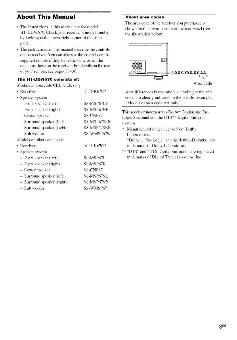
About area codes
The area code of the receiver you purchased is
shown on the lower portion of the rear panel (see
the illustration below).
Area code
Any differences in operation, according to the area
code, are clearly indicated in the text, for example,
"Models of area code AA only".
This receiver incorporates Dolhy" Digital and Pro
Logic Surround and the DTS'" Digital Surround
System.
• Manufactured under license ftom Dolby
Laboratories.
"Dolby","Pro Logic" and the double-D symbol are
trademarks of Dolby Laboratories.
"'" "DTS" and "DTS Digital Surround" are registered
trademarks of Digital Theater Systems, Inc.
3GB
i!i! ¸'¸¸'¸¸'
Getting Started
1: Check how to hookup your
components ....................................... 5
I a: Connecting components with
digital audio output jacks ........... 7
I b: Connecting components with only
analog andio jacks ...................... 9
2: Connecting the antennas ................... 10
3: Connecting speakers ......................... 11
4: Connecting the AC power cord ........ 14
5: Setting up the speakers ..................... 15
6: Adjusting the speaker levels and
balance ............................................ 17
TEST TONE
Amplifier Operation
Selecting the component ....................... 18
Listening to FM/AM radio .................... 19
Storing FM stations automatically ........ 20
-- AUTOBETICAL
(Models of area code CEL, CEK
only)
Presetting radio stations ........................ 20
Using the Radio Data System (RDS).... 21
(Models of area code CEL, CEK
only)
Changing the display ............................. 23
About the indications in the display ...... 24
Enjoying Surround Sound
Using only the front speakers and sub
woofer ............................................. 25
-- 2CH STEREO
Enjoying higher fidelity sound .............. 25
AUTO FORMAT DIRECT
Selecting a sound field .......................... 26
Advanced Adjustments and
Settings
Switching the audio input mode for digital
components ..................................... 28
INPUT MODE
Customizing sound fields ..................... 28
Adjusting the tone ................................. 30
Advanced settings ................................. 30
Other Operations
Naming preset stations and inputs ........ 32
Using the Sleep Timer .......................... 32
Operations Using the Remote
RM-AAU002
Be_re you nse your remote .................. 33
Remote button description .................... 33
Changing the factory setting of an input
button .............................................. 36
Additional Information
Precautions ........................................... 37
Troubleshooting .................................... 38
Specifications ....................................... 40
List of button locations and reference
pages ............................................... 43
Index ...................................... Back Cover
4_B
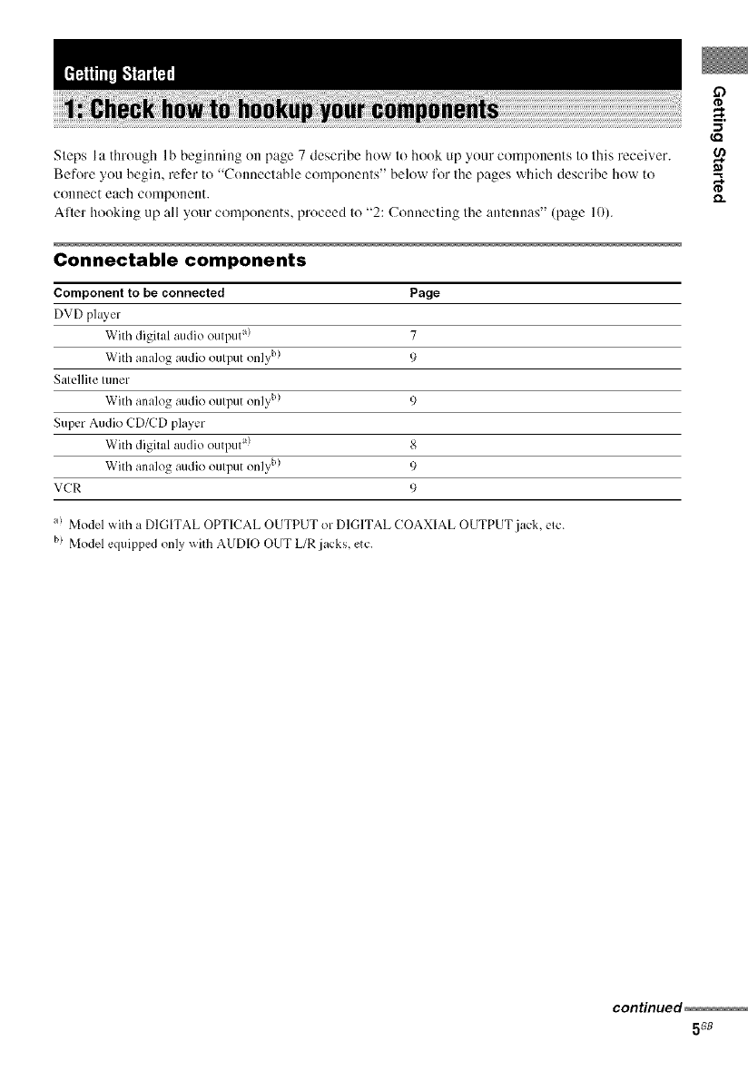
Steps Ia through 1b beginning oi1 page 7 describe how to hook up your components to this receiver.
Before you begin, refer It) "Connectable components" below for the pages which describe how 1o
connect each con_ponent.
Aller hooking up all your components, proceed to "2: Connecting the antennas" (page 10).
Connectable components
Component to be connected Page
DVD ph L_,er
With digital audio output a) 7
With analog audio output only b) 9
Satellite tuner
With analog audio output only b) 9
Super Audio CD/CD player
With digital audio output a) 8
With analog audio output only b) 9
VCR 9
a! Model with a DIGITAL OPTICAL OUTPUT or DIGITAL COAXIAL OUTPUT jack, etc.
b) Model equipped only with AUDIO OUT L/R jacks, etc.
,m
continued
5G8
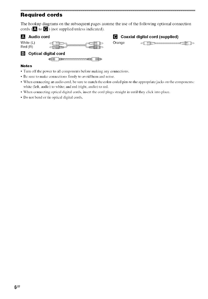
Required cords
The hookup diagrams on the subsequent pages assume the use of the lbllowing optional connection
cords (1_ to r_) (not supplied unless indicated).
[] Audio cord [] Coaxial digital cord (supplied)
White (L) Orange @ @
Red (R)
[] Optical digital cord
Notes
•Turn off tile po_er to all components belbre m_king any connections.
•Be sure to make connections firmly to avoid hum and noise.
• When connecting an audio cord, be sure to match the color-coded pins to the appropriate jacks on the components:
white (left, audio) to white: and red (right, audio) to red.
• When connecting optical digital cords, insert the cord plugs straight in until they click into place.
• Do not bend or tie optical digital cords.
6G8
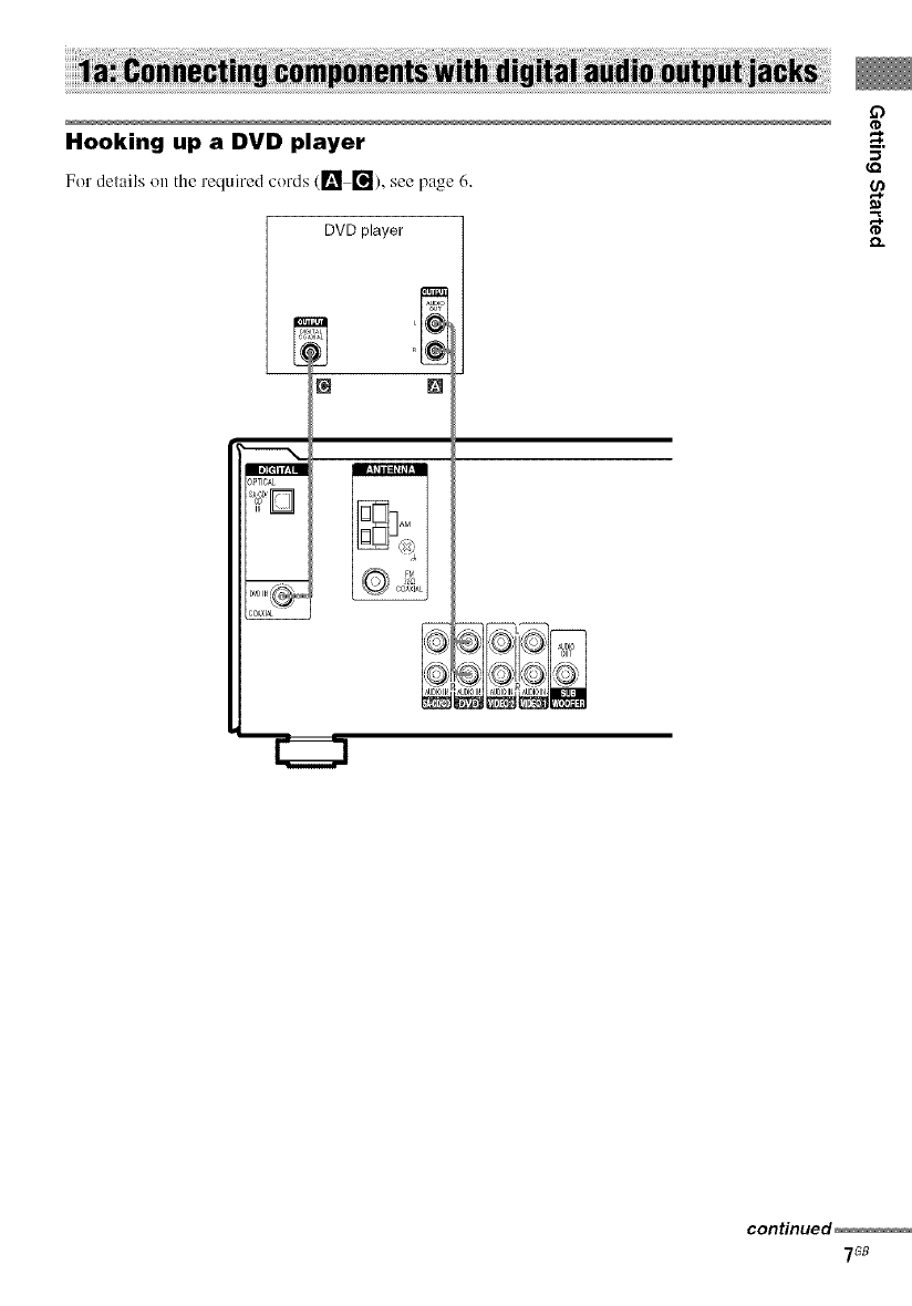
Hooking up a DVD player
For del;tils on the required cords (1_ _), see p;tgc 6,
DVD player
r_ m
Ill[eli f_ II
_PTICAL
_OA_I_
conHnued
7G8
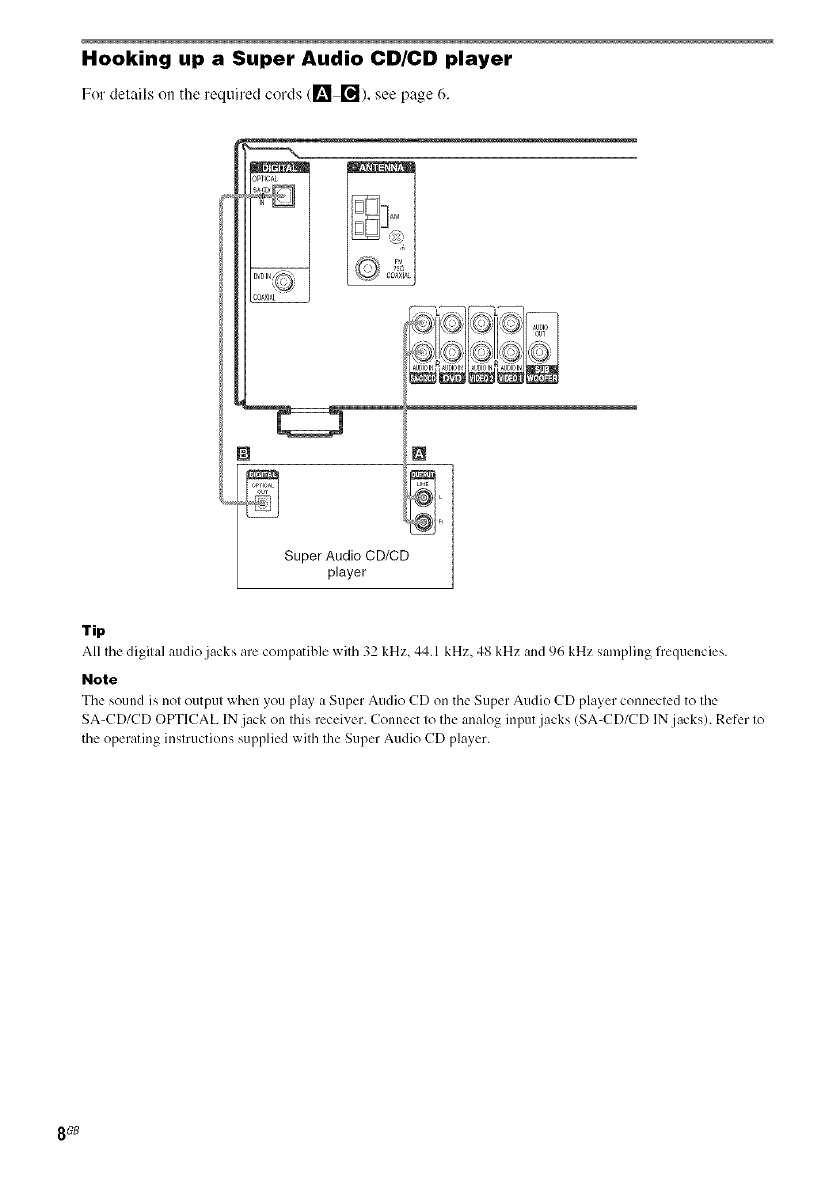
Hooking up a Super Audio CD/CD player
For delails on tile required cords (l_ re]), see page 6.
Super Audio CD/CD
player
Tip
All tile digital audio jacks are compatible with 32 kHz, 44.1 kHz, 48 kHz and 96 kHz sampling frequencies.
Note
Tile somld is not output _ hc.n you pl_y _ Super Audio CD on the Super Audio CD player connected to tile
SA-CD/CD OPTICAL IN jack on this receiver. Connect to the analog input jacks (SA-CD/CD IN jacks). Refer to
tile operating instructions supplied with the Super Audio CD player.
8GB
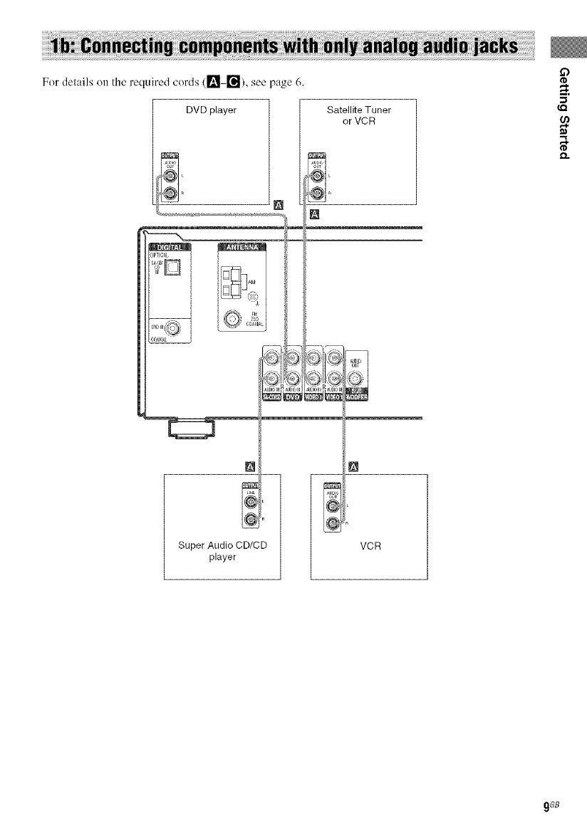
For delails on the required cords ([_ _), see page 6.
DVD player Satellite Tuner
or VCR
£3
{,Q
[]
Super Audio CD/CD
player
[]
VCR
9GB
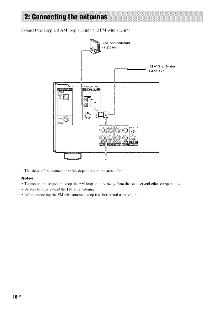
Ctmnecl the supplied AM loop anlenna and FM wire anlmma.
_,j_ AM loop antenna
(supplied)
......... _ (FMppilledlntenna
The shape of the connector varies depending on tile area code.
Notes
• To prevent noise pickup, keep the AM loop antenna a_ay from the receiver and other components.
• Be sure to fully extend Ihe FM wire antenna.
• After comlecting the FM wire antenna, keep it as horizontal as possible.
10G8
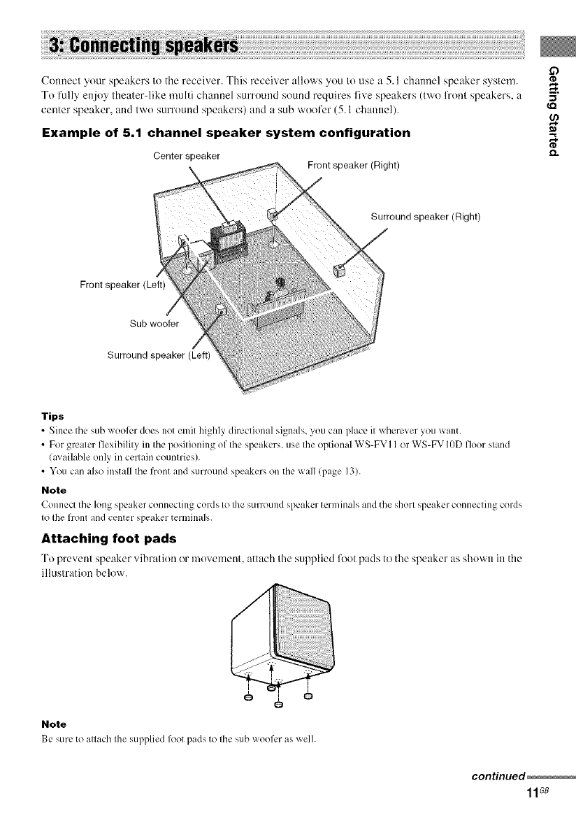
Connect your speakers to the receiver. This receiver allows you to use a 5.1 channel speaker system.
To l'ully enjoy theater-like multi channel surround sound requires live speakers (two fi'ont speakers, a
center speaker, and two surround speakers) and a sub woofer (5.1 channel).
Example of 5.1 channel speaker system configuration
Center speaker Front speaker (Right)
Surround speaker (Right)
Front speaker (Left)
Sub woofer
Surround speaker (Left)
Tips
•Since the sub wool)r does not emit highly directional signals, you can place it x_herever you x_ailt.
• For greater flexihility in the positioning of the speakers, use the optional WS-FV I I or WS-FV IgD floor stand
lax ailable only in cel_ain countries).
• You can also install the front and surround speakers on the x_all (page 13).
Note
Connect the long speaker connecting cords to the surround speaker terminals _md the short speaker connecting cords
to the front and center speaker terminals.
Attaching foot pads
To prevent speaker vibration or movement attach the supplied _x)t pads to the speaker as shown in the
illustration below.
Note
Be sure to attach the supplied lk)otpads to the sub wool)r as well.
continued
11Gs
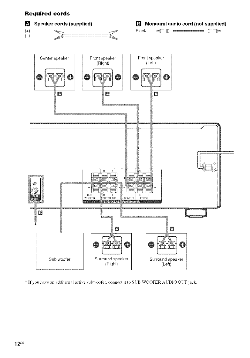
Required cords
[] Speaker cords (supplied)
(+)
[] Monaural audio cord (not supplied)
Black @
Center speaker 1 Front speaker ] Front speaker
(Right) / (Left)
o
"-If yet] hi_ e an additional active subx_oofcr, connect it to SUB WOOFER AUDIO OUT jack.
12_
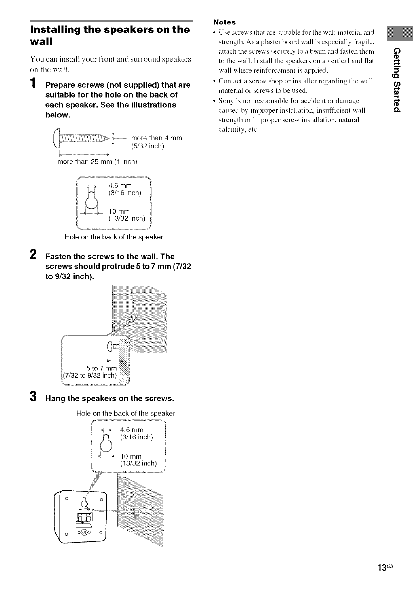
Installing the speakers on the
wall
You can install your front and surround speakers
<)i1the wall.
1Prepare screws (not supplied) that are
suitable for the hole on the back of
each speaker. See the illustrations
below.
more than 4 mm
(5/32 inch)
4
more than 25 mm (1 inch)
Notes
•Use screws that are suitable for Ihe wall malerial and
slrenglh. As a plasler board wall is especially fragile,
altach the screws securely Io a beam and faslen tbem _:_
te Ihc wall Install Ihe speakers on a verlical and flat
wall where reinforcement is applied. (.Q
•Conlact a screw shop or installer regarding the wall O_
material or screws le be used.
•Sony is not responsible for accident or damage _,
caused hy improper inslalb_tien, insufficienl wall e_
slrength or iml_roper screw installatien, natural
calamily, elc.
2
Hole on the back of the speaker
Fasten the screws to the wall. The
screws should protrude 5 to 7 mm (7/32
to 9/32 inch).
3Hang the speakers on the screws.
Hole on the back of the speaker
f,, * 4.6 mm
_ (3/16 inch)
¢ _- lOmm
(13/32 inch)
13G8
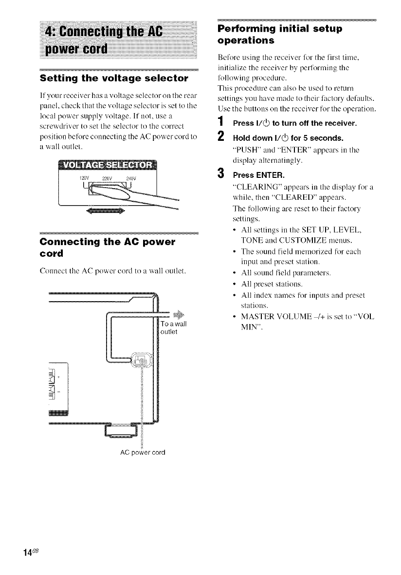
Setting the voltage selector
If your receiver has a voltage selector on the rear
panel, check that the voltage selector is set to the
local power supply voltage. If not, use a
screwdriver to set the selector to the correct
position belore connecting the AC power cord to
a wall outlet.
Connecting the AC power
cord
Connecl the AC power cord to a wall oullet.
To a wall
outlet
Performing initial setup
operations
Before using Ihe receiver h)r the lirst lime,
inilialize the receiver by performing the
fl)llowing procedure.
This procedure can also be used lo return
settings you have made Io their faclory defaults.
Use the bullOllS on Ihe receiver for lhe operation.
1Press I/@ to turn off the receiver.
2Hold down I/_ for 5 seconds,
"PUSH" and "ENTER" appears in the
display allernalingly.
3Press ENTER.
"CLEARING" appears in tile display for a
while, then "CLEARED" appears.
The following are reset 1(!Iheir factory
sellings.
• All seltings in the SET UP, LEVEL,
TONE and CUSTOMIZE menus.
• The sound field memorized for each
inpul and preset stalion.
• All sound field paramelers.
• All presel slatious.
• All index names for inputs and presel
stations.
• MASTER VOLUME 1+ is set to'WOE
MIN'.
AC power cord
14GB
You can use Ihe SET UP lneuu lu sel the
dislance and location ol lhe speakers connected
to Ihis receiver.
1Press I/@ to turn on the receiver.
2 Press MAIN MENU repeatedly to select
"<SET UP >".
3 Press <_ or _repeatedly to select the
parameter you want to adjust.
For details, see "Speaker setup parameters"
below.
4
5
Note
Some speaker setup items may appear dimmed in
tile display. This means that Ihey have been
a_(iusted automatically clue to other speaker
settings or may not be a_(iustable.
Press + or - repeatedly to select the
setting you want.
The setting is entered automatically.
Repeat steps 3 and 4 until you have set
all of the items that follow.
Speaker setup parameters
The initial setting is underlined.
•:)J {L?:: DIST. X.X m(XX ft.)*
(Front speaker distance)
Initial setting: 3.0 m ( 10 fl)
Lets you set the distance from your listening position
to the front speakers (_). You can adjust from 1.0
meter to 7.0 meters (3 to 23 feet) in 0. I meter (I foot)
steps.
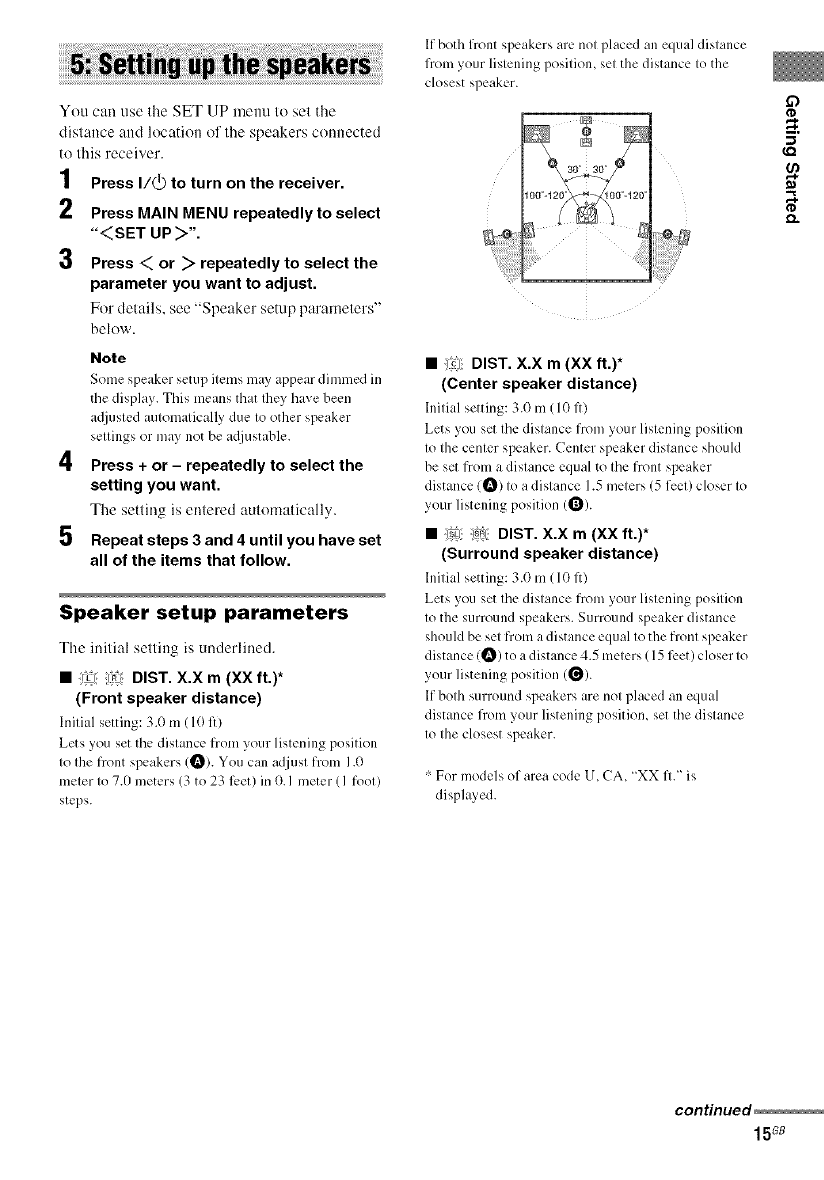
If both front speakers are nol placed an equal distance
from your lislening posilion, sel the distance Io the
closest speaker.
• !l?Jl;DIST. X.X m(XX ft.)*
(Center speaker distance)
Initial setting: 3.0 m (10 fl)
Lets you set the distance from your listening position
to the center speaker. Center speaker distance should
be set from a distance equal to the front speaker
distance (_) to a distance 1.5 meters (5 feet) closer to
your listening position (_).
•:!_Lj_)_1: DIST. X.X m(XX ft.)*
(Surround speaker distance)
Initial setting: 3.0 m(10 fl)
Lets you set the distance from your listening position
to the surround speakers. Surround speaker distance
should be set from a distance equal to the front speaker
distance (_) to a distance 4.5 meters ( 15 feet) closer to
your listening position (_).
If both surround speakers are not placed an equal
distance flom your listening position, set tile distance
to the closest speaker.
For models of area code U. CA, "XX ft." is
displayed.
continued
15G8
Tip
Tile receiver lets you to input the speaker position in
terms of distance. However, it is not possible to set tile
center speaker further than the front speakers. Also, tile
center speaker cannot be set more than 1.5 meters
(5 feet) closer than the front speakers.
Likewise, the surround speakers cannot be set fllrther
away from the listening position than the front
speakers. And they can be no more than 4.5 meters
(15 feet) closer.
This is because incorrect speaker placement is not
conducive to the enjoyment of surround sound.
Please note Ihat, setting the speaker distance closer than
the actual location of the speakers will cause a delay in
the output of the sound from Ihat speaker. In other
words, the speaker will sound like it is fllrther away.
For example, setting the center speaker distance 1 2
meters (3-6 feet) closer than the actual speaker position
will create al.firly realistic sensation of being "inside"
the screen. If you cannot obtain a satisfactory surround
effect because the surround speakers are too close,
setting the sunound speaker distance closer (shorter)
than the actual distance will create a larger sound stage.
Adjusting these parameter while listening to the sound
often results in much better surround sound. Give it a
try!
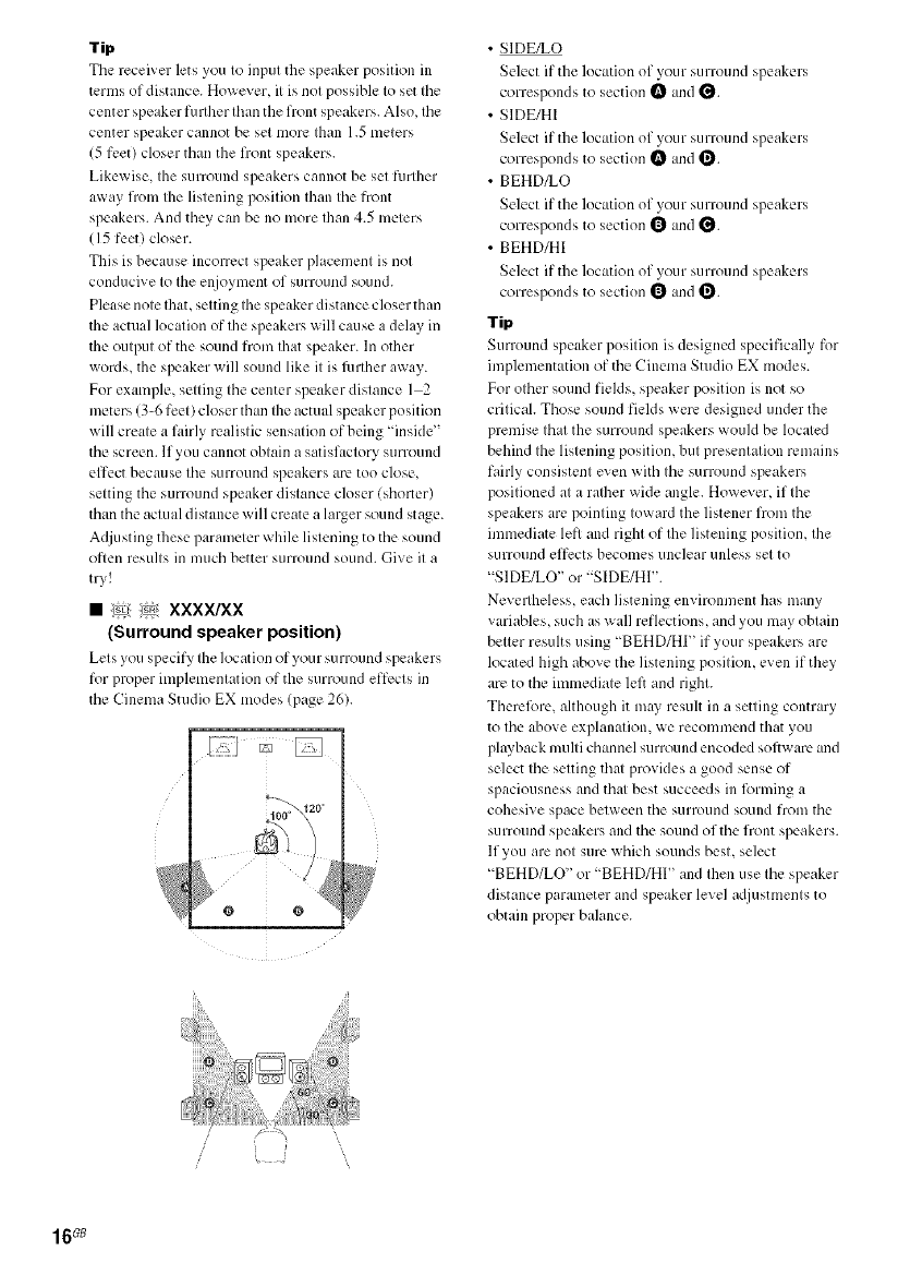
• _: :_ xxxx/xx
(Surround speaker position)
Lets you specify the location of your surround speakers
for proper implementation of the surround effects in
the Cinema Studio EX modes (page 26).
@ @
• SIDE/LO
Select if the location of your surround speakers
correspoMs to section _ and _.
• SIDE/HI
Select if the location of your surround speakers
correspoMs to section _ and _.
• BEHD/LO
Select if the location of your surround speakers
correspoMs to section 1_ and _.
• BEHD/HI
Select if the location of your surround speakers
correspoMs to section 1_ and _.
Tip
Surround speaker position is designed specifically for
implementation of the Cinema Studio EX modes.
For other sound fields, speaker position is not so
critical. Those sound fields were designed under the
premise that the surround speakers would be located
behind the listening position, but presentation remains
fairly consistent even with the surround speakers
positioned at a ralher wide angle. However, if the
speakers are pointing toward the listener from the
immediate left and right of Ihe listening position, the
stlrround effects becomes unclear unless set to
"SIDFJLO" or "S[DE/HI".
Nevertheless, each listening environment has many
variables, such as wall reflections, and you may obtain
better results using "BEHD/HI" if your speakers are
located high above the listening position, even if they
are to the immediate lel}and right.
Therefi_re, although it may result in a setting contrary
to the above explanation, we recommend that you
plwback multi channel surround encoded sofl_ are and
select the setting that provides a good sense of
spaciousness and that best succeeds in forming a
cohesive space between the surround sound from the
surround speakers and the sound of the front speakers.
lfyou are not sure which sounds best, select
"BEHD/LO" or "BEHD/HI" and then use the speaker
distance parameter and speaker level adjustments to
obtain proper balance.
16_
-- TEST TONE
Adjust the speaker levels and balance while
listeuiug to the test tone l?'om your listening
position. Use the remote for the operation.
Tip
The receiver employs a test tone with a frequency
centered at 800 Hz.
1Press I/_ to turn on the receiver.
2 Press TEST TONE.
"T. TONE" appears in tile display and the
test toue is output from each speaker in
sequence.
Frout (left) _ Center _ Front (right)
Surround (right)--+ Surround (lell)--+ Sub
woofer
3
4
Adjust the speaker levels and balance
using the LEVEL menu so that the level
of the test tone sounds the same from
each speaker.
For details on the LEVEL menu settings,
see page 28.
Tips
•To a_liust the level of all speakers at the same
time, press MASTER VOL +1 on the remote or
turn MASTER VOLUME /+ on the receiver.
• The adjusted value are shown in the display
during a_liustment.
Press TEST TONE again after
adjustment.
The test tone turns ofl.
Note
Although these adjustments can also be made via the
front panel using the LEVEL menu (when the test tone
is output, the receiver switches to the LEVEL menu
automatically), we recommend you follow the
procedure described above and adjust the speaker
levels from your listening position using the remote.
17GB
4
I Press input buttons to select the input.
To select the Press
VCR VIDEO I or
VIDEO 2
Satellite tuner VIDEO 2
DVD player DVD
Super Audio CD or SA-CD/CD
CD player
Built-in tuner (FM/AM) FM or AM
The selected input appears in the display.
2Turn on the component and start
playback.
Note
lt'you select any video components, set tile TV_s
video input to match the component you selected.
3 Turn MASTER VOLUME 4+ to adjust
the volume.
Note
To a_oid dmnaging your speakers, make sure that
you turn down the volume beli_re you turnoft"the
receiver.
To mute the sound
Press MUTING on the remote.
The muting function will be canceled when you
do the lk)llowing.
• Press MUTING on the remote again.
• Turn the power off.
• Increase the volume.
To use the headphones
Connect lhe headphones to the PHONES jack.
• When the headphones are connected, speaker
output is automatically canceled and "SP"
does not light up in the display.
• When the headphones are connected, you can
select only the following sound fields
(page 27).
- HP 2CH (HEADPHONE 2CH)
- HP THEA (HEADPHONE THEATER)
18_
You can listen to FM aud AM broadcasts
through the built-in tuner. Before operatitm.
make sure you have ctmnected the FM and AM
antennas to the receiver (see page 10).
Tip
The tuning scale dilli:rs depending on Ihe area code as
shown in tile fi)llowing table. For details on area codes,
see page 3.
Area code FM AM
U, CA Ill0 kHz 10 kHz*
CEL, CEK, SP, AU 50 kHz 9 kHz
MX 50 kHz I0 kHz
E51 5//kHz 10 kHz:'-
L,The AM tuning scale can be changed (see page 41/.
Automatic tuning
If you do 11olkuow the l)'equency ollhe slation
you waul, you can lel the receiver scau all
available slatious in your area.
1Press FM or AM to select the FM or AM
band.
The lasl received slalion is luned in.
2Press TUNING + or TUNING-.
Press TUNING + to scan from low lo high;
press TUNING - lo scan from high lo low.
The receiver slops scanuing whenever a
slaliou is received.
Tip
If _STEREO" flashes in the display and the FM stereo
reception is poor, press FM MODE to change to
monaural (MONO). You will not be able to et\ioy the
stereo effect, but the sound will be less distorted. To
return to stereo mode, press FM MODE again.
Direct tuning
You can euter the fi'equeucy of the station you
waut directly. Use the remote liar the operatiou.
1Press TUNER repeatedly to select the
FM or AM band.
The last received statitm is tuued iu.
2
3
Tip
You can also use FM or AN] on Ihe receiver.
Press D.TUNING.
Press the numeric buttons to enter the
frequency.
Exmnple 1: FM 102.50 MHz
Press 1 *- 0 ,_-2 ,_-5 ,_-0
Example 2: AM 1,350 kHz
Press 1 *- 3 ,_-5 ,_-(t
(You do not have to enter the last "0" when
the tuniug scale is set to I0 kHz.)
If you have tuned in an AM slatiou, adjusl
the direction of the AM loop auteuna for
optimum receplitm.
If you cannot tune in a station
and the entered numbers flash
Make sure you have entered the right frequency.
11not. repeat steps 2 and 3. If the entered
tmmbers still flash, lhe frequency is uol used in
your area.
3
"o
m
n,
O
"o
I gG8
-- AUTOBETICAL
(Models of area code CEL, CEK only)
This lnuctiou lets you store up to 30 FM and FM
RDS stations in alphabetical order without
redundaucy. Additioually, it ouly stores the
stations with the clearest signals.
If you want to store FM or AM stations oue by
one, see "Presetting radio statious" (page 20).
Use the buttons ou the receiver lor the operation.
1Press I/@ to turn off the receiver.
2Hold down MEMORY and press I/_ to
turn the receiver back on.
"AUTO-BETICAL SELECT' appears in
the display and the receiver scaus and stores
all the FM and FM RDS stations in the
broadcast area.
For RDS statious, the tuner first checks for
stations broadcastiug the same program,
then stores only the one with the clearest
sigual. The selected RDS statious are sorted
alphabetically by their Program Service
uame, theu assigued a 2-character preset
code. For more details on RDS, see
page 21.
Regular FM statious are assigned 2-
character preset codes and stored after the
RDS station.
When done, "FINISH" appears in the
display momentarily aud the receiver
returns to the normal operation.
Notes
• Do not press ally button on the receiver or supplied
remote during aulobetical operalion, excepl I/(_).
• If you move to another area, repeat this procedure to
store stations ill your new area.
• For details on tuning the stored stations, see "Tuning
to preset stations" (page 21).
• If you move the antenna after storing stations with
this procedure, the stored settings may no longer be
valid. If this happens, repeat this procedure to store
the stations again.
You can preset up to 30 FM or AM stations.
Theu you cau easily tune in the statious you
often listen to.
Presetting radio stations
1Press FM or AM to select the FM or AM
band.
The last received station is tuned iu.
€11
_, Tune in the station that you want to
preset using Automatic Tuning
(page 19) or Direct Tuning (page 19).
3 Press MEMORY,
"MEMORY" appears in the display for a
lew seconds. Do steps 4 to 5 belore the
display goes out.
4Press PRESET TUNING + or PRESET
TUNING - repeatedly to select a preset
station number,
Each time you press the hutton, you can
select the preset statiou number as follows:
If "MEMORY" goes out belore you select
the preset station number, start again h'om
step 3.
Tip
You can also use the remote to select a preset
station number. Press SHIFT repeatedly to select
a memory page (A, B or C) and then press the
n/imeric b/ittons to select a preset nomber.
Press MEMORY again.
The statiou is stored to the selected preset
Uulnber.
If "MEMORY" goes out before you press
MEMORY, start again from step 3.
Repeat steps 2 to 5 to preset another
station,
20_
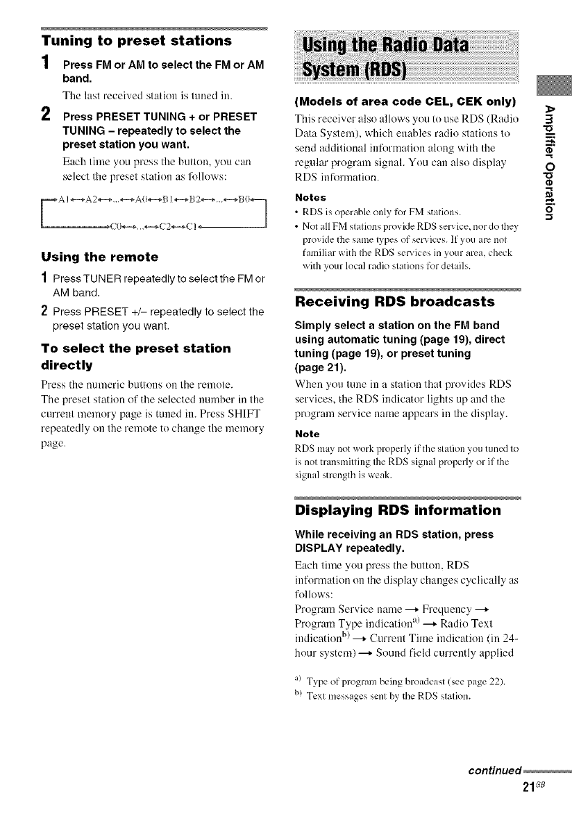
Tuning to preset stations
1Press FM or AM to select the FM or AM
band.
The last received slatitm is luued in.
2 Press PRESET TUNING + or PRESET
TUNING - repeatedly to select the
preset station you want.
Each lime yeu press tile butlen, you can
selecl the presel slatien as follows:
Using the remote
1Press TUNER repeatedly to select the FM or
AM band.
2Press PRESET +/- repeatedly to select the
preset station you want.
To select the preset station
directly
Press the numeric buttons on the remote.
The preset station of the selected number in the
current memory page is tuned in. Press SHIFT
repeatedly on the remote to change the memory
page.
iiiiUS!!i!i!!ii!'__!ii!i_;_i;:!ilili!ii!i]i!n_giii!i!i!it!h_ii_i_i_iKad!|i!o_Dataiiiiiiiiiiiiiiiiiiiiiiiiiiiiiiiiiiiiiiiiiiiiiiiiiiiiiiiiiiiiiiiiiii_!!_!_!i_i_ii;_:_;_);_i!i!_i!i!i!i!iiiiiiii!iiiii;iillii;i!ii_iiiiiiiiiiiil!i!!i!iiii!illi!i!i!i¸!;i_i;_!!i!!i!i!iiiillii!ii!;ii!ii:__:i:i:i_:i_;:i_iliiiii!_i_!i;;:__:i!!!_iii_i_i!i_!iiiiiiii!iii_i!ii!iii!i!i!iiiiiiiiiiiiiiiiiiiiiiiiiiiiiiiiiiiiiiiiiiiiiiiiiiiiiiiiiiiiiiii!i!ii!iiiiiiiiii!ii
(Models of area code CEL, CEK only)
This receiver also allows you to use RDS (Radio
Data System), which enables radio stations to
send additieual infermatien along with tile
regular program siguah You can also display
RDS information.
Notes
•RDS is operable only for FM stations.
•Not all FM stations provide RDS service, nor do they
provide the same lypes of ser',ices. If you are not
familiar with the RDS services in your area, check
with your local radio stations for details.
Receiving RDS broadcasts
Simply select a station on the FM band
using automatic tuning (page 19), direct
tuning (page 19), or preset tuning
(page 21).
When you tune in a station thai provides RDS
services, the RDS indicator lights up and tile
program service name appears iu the display.
Note
RDS may not _ork properly it"the station you tuned to
is not transmitting the RDS signal properly or if the
signal strength is weak.
Displaying RDS information
While receiving an RDS station, press
DISPLAY repeatedly.
Each time you press the button, RDS
information on the display changes cyclically as
follows:
Pregram Service name _ Frequency ---+
Program Type indication a) _ Radio Text
indication b) ---+ Current Time indication (in 24-
hour system) ---+ Sound field currently applied
a} Type of program being broadcasl (see page 22 .
bl Texl messages senl by the RDS slalion.
3
"o
m
n,
O
-1
continued
21G8
Notes
•If Ihere is an emergency announcement by
governmenl authorities. 'ALARM" flashes in Ihe
display.
• When Ihe message consists of 9 characters or more,
tile message scrolls across tile display.
• Ifa station does not provide a particular RDS service,
<NO XXXX" (such as 'NO TEXT") appears in the
display.
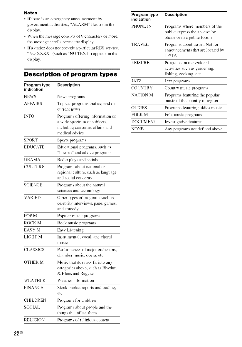
Description of program types
Program type Description
indication
NEWS Ne_s programs
AFFAIRS Topical programs that expand ol1
currerlt news
INFO Programs offering inl\_rmation ol3
a wide .,pecmlm of _,uI2iects,
including consumer afl.urs and
medical advice
SPORT Sports programs
EDUCATE Educational programs, such as
'13ow-to" and advice programs
DRAMA Radio plws and serials
C ULTURE Programs ahout national or
regional culture, such as language
and social concerns
SCIENCE Programs ahout the natural
s_iences and technology
VARIED Other types of programs such as
celebrity interviews, panel games,
m_d comedy
POP M Popular music programs
ROCK M Rock music programs
EASY M Easy Listening
LIGHT M Instrumental, vocal, and choral
I11/IgiC
CLASSICS PerR_rmances of m_tjor orchestras,
chamber music, opera, etc.
OTHER M Music Ihat does not fit into any
categories above, such as Rhythm
& Blues and Reggae
WEATHER Weather information
FINANCE Stock market reports and trading,
etc.
CHILDREN Programs for chiklren
SOCIAL Programs ahout people and the
things that affect them
REEl(lION Programs of religious content
Program type Description
indication
PHONE IN Programs where members of the
public express their views by
phone or in a punic lorcun
TRAVEL Programs ahout travel. Not for
announcements that are located by
TP/TA
LEISURE Programs on recreational
activities such as gardening,
fishing, cooking, etc.
JAZZ Jazz programs
COUNTRY Coumry music program_,
NATION M Programs featuring Ihe popular
music of the country or region
OLDIES Programs featuring oldies music
FOLK M Folk music programs
DOCUMENT lnvestigati_ e features
NONE Any programs not defined ahove
22_
Changing the information in
the display
You can check the sound field etc. by changing
the information in the display.
Press DISPLAY repeatedly.
Each time you press DISPLAY. the display ,sill
change cyclically as Follows.
Index name of the input* _ Selected input ---+
Sound field currenlly applied
When the tuner is selected
Program Service name *_ or preset stalion name I
---+ Frequency _ Program Type indication**
Radio Text indication *__ Current Time
indication (in 24qlour system) _ ---+ Sound field
currently applied
'" lndex name appears only when you ha;e assigned
one to the input or preset station (page 32). lndex
name does not appear when only blank spaces have
been entered, or it is the same as the input name.
"'" During RDS reception only. (Models of area code
CEL, CEK only. See page 2I.)
Adjusting the brightness of
the display
Press DIMMER repeatedly.
The hrightness of the display will change in 3
steps.
3
m
n,
0
"o
o
23G8
SLEEP OPT COAX
[]
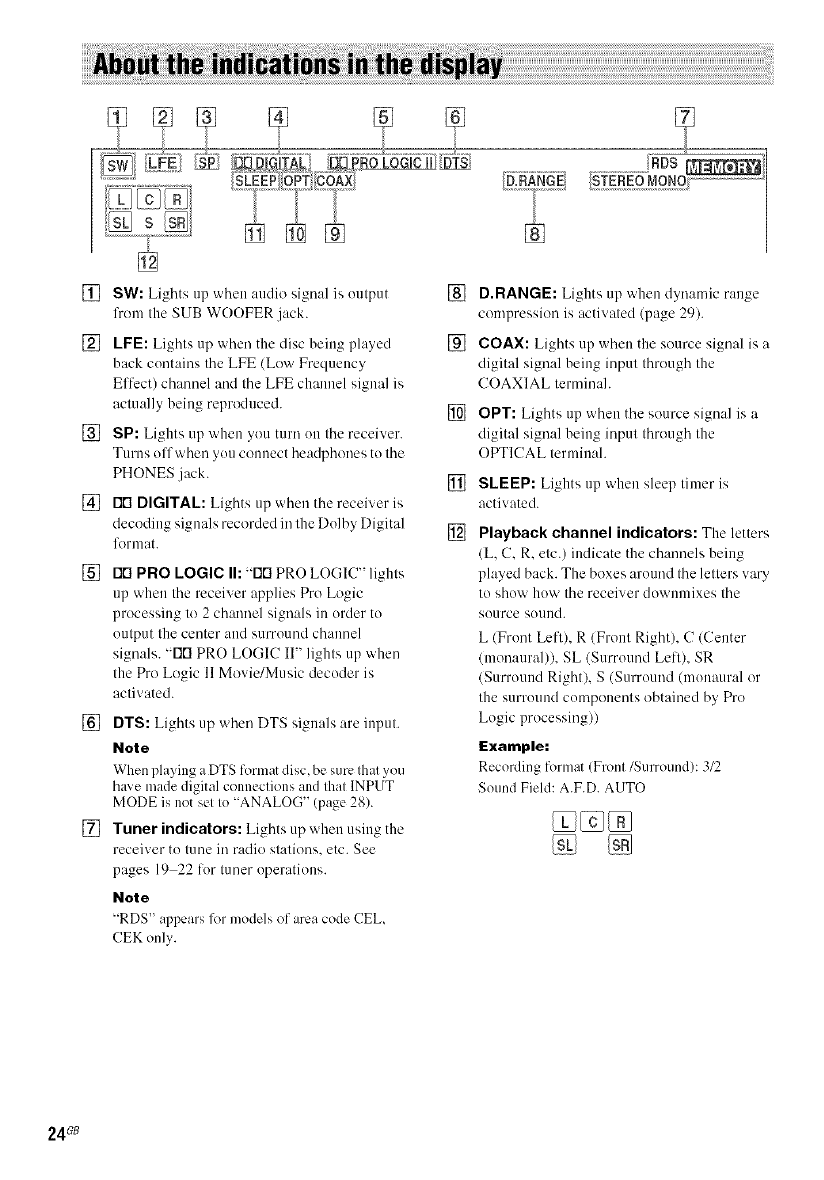
[] SW: Lights up when audio signal is output []
lhom the SUB WOOFER jack.
[] LFE: Lights up when the disc being played []
back contaios the LEE (Low Frequency
Eflcct) channel and the LFE channel signal is
actually being reproduced. []
[] SP: Lights up when you turn on the receiver.
Turns off when you connect headphones to the
PHONES jack. []
[] rlrt DIGITAL: Lights up when the receiver is
decoding signals recorded in the Dolby Digital []
12armat.
[] rlrl PRO LOGIC I1:-rlrl PRO LOGIC" lights
up when the receiver applies Pro Logic
processing to 2 channel signals in order to
output the center and surround channel
signals. "FIRPRO LOGIC II" lights up when
the Pro Logic 11Movie/Music decoder is
activated.
[] DTS: Lights up when DTS signals are input.
Note
When playing a DTS format disc, he sure that you
haxe made digital connections and that INPUT
MODE is not set to "ANALOG" (page 28).
[] Tuner indicators: Lights up when using the
receiver to tune iraradio stations, etc. See
pages 19 22 lor tuner operations.
Note
"RDS appears 1_1models of area code ('EL,
CEK only.
D.RANGE: Lights up when dynamic range
compression is activated (page 29).
COAX: Lights up when the source signal is a
digital signal being input through the
COAXIAL terminah
OPT: Lights up when the source signal is a
digital signal being input through the
OPTICAL lerminah
SLEEP: Lights up when sleep timer is
activated.
Playback channel indicators: The letters
(L, C, R, etc.) indicate the channels heing
played back. The boxes around the letters wiry
to show how the receiver downmixes the
source sound.
L (Front Left), R (Front Right), C (Center
(monaural)), SL (Surround Lell), SR
(Surround Right), S (Surround (monaural or
the surround components obtained by Pro
Logic processing))
Example:
Recording fommt (Front/Surround): 3/2
Sound Field: A.F.D. AUTO
24Gs
--2CHSTEREO
In this mode, the receiver oulputs the sound
from the fl'ont lefl/right speakers and sub
woofer.
When multi channel surround formats are input,
the signals are downmixed to 2 channel with
bass fl'equencies being output l?'omthe sub
woofer.
When standard 2 channel stereo sources are
input, the receiver's bass redirection circuitry
will be activated. The front channel bass
frequencies will be output from the sub woofer.
Press 2CH.
"2CH ST." appears in the display and the
receiver switches to the 2CH STERE() mode.
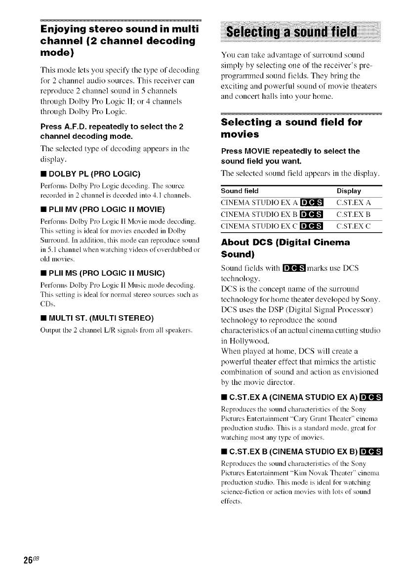
-- A UTO FORMAT DIRECT
The Auto Format Direct (A.F.D.) mode allows
you to select the decoding mode you want for rn
your audio sound. _.
o
A.F.D. mode Decoding mode ,<
(Display) ._"
_Q
A.F.D. AUTO As encoded (D
(A.F.D. AUTO)
PRO LOGIC Dolby Pro Logic O
(DOLBY PL) _.
PRO LOGIC I1MOVIE Doiby Pro Logic 11 €.D
O
(PLII MV) l-
PRO LOGIC II MUSIC _.
(PLII MS)
MULTI STEREO
(MULTI ST.)
Decoding the input audio
signal automatically
In this mode, the receiver automatically detects
the type of audio signal being input (Dolby
Digital, DTS, standard 2 channel stereo, etc.)
and performs the proper decoding if necessary.
This mode presents the sound as it was recorded/
encoded, without adding any surround eflects.
However, if there are no low l?'equency signals
(Dolby Digital LFE, etc.) it will generate a low
frequency signal for output to the sub woofer.
Press A.F.D. repeatedly to select "A.F.D.
AUTO".
The receiver automatically detects the type of
audio signal being input and perli)rms the proper
decoding if necessary.
continued
25G8
Enjoying stereo sound in multi
channel (2 channel decoding
mode)
This mode lets you specify tile type of decoding
lor 2 channel audio sources. This receiver can
reproduce 2channel sound in 5 channels
through Dolby Pro Logic 11;or 4 channels
through Dolby Pro Logic.
Press A.F.D. repeatedly to select the 2
channel decoding mode.
Tile selected type of decoding appears in ttle
display.
•DOLBY PL (PRO LOGIC)
Performs Dolby Pro Logic decoding. The source
recorded in 2 channel is decoded into 4. I channels.
•PLII MV (PRO LOGIC II MOVIE)
Performs Dolby Pro Logic 11 Movie mode decoding.
This setting ix ideal lbr movies encoded in Dolby
Surround. In addition, this mode can reproduce sound
in 5.1 channel x_hen watching videos of overdubbed or
old movies.
•PLII MS (PRO LOGIC II MUSIC)
Performs Dolby Pro Logic 11 Music mode decoding.
This setting ix ideal lbr normal stereo sources such as
CDs.
•MULTI ST. (MULTI STEREO)
Output the 2 chl,nnel L/R signals from all speakers.
You can take advantage of surround sound
simply by selecting one of the receiver's pre-
programmed sound fields. They bring the
exciting and powerlul sound of movie theaters
and concert halls into your home.
Selecting a sound field for
movies
Press MOVIE repeatedly to select the
sound field you want.
The selected sound t'ield appears in the display.
Sound field Display
CINEMA STUDIO EX A _ C.ST.EX A
CINEMA STUDIO EX B ri'lr'_lk-_ C.ST.EX B
CINEMA STUDIO EX C _ C.ST.EX C
About DCS (Digital Cinema
Sound)
Sound [ields with r_lr_'atmarks use DCS
technology.
DCS is the concept name of the surround
technology for home theater developed by Sony.
DCS uses the DSP (Digital Signal Processor)
techuology to reproduce the sound
characteristics of an actual cinema cutting studio
in Hollywood.
When played at honle. DCS will create a
powerful theater effect that mimics the artistic
combination of sound and action as envisioned
by the movie director.
• C.ST.EX A(CINEMA STUDIO EX A)
Reproduces the som_dcharacteristics of the Sony
Pictures Entellainment "Cary Grant Theater" cinema
production studio. This is a standard mode, great lbr
watching most any type of movies.
• C.ST.EX B(CINEMA STUDIO EX B)
Reproduces the sound ch;m_cteristics of the Sony
Pictures Entertainment "Kim Novak Theater" cinema
production studio. This mode is ideal for watching
science-fiction or action movies with lots of sound
effects.
26_
• C.ST.EX C (CINEMA STUDIO EX C)
Reproduces the sound chmacteristics of the Sony
Pictures Entertainment scoring stage. This mode is
ideal for watching musicals or fihns where orchestra
music is featured in the soundtrack.
About CINEMA STUDIO EX modes
CINEMA STUDIO EX modes are suitable lk)r
watching motion picture DVDs (etc.), with
multi channel sum)und effects. You can
reproduce the sound characteristics of Sony
Pictures Entertainment's dubbing studio in your
home.
The CINEMA STUDIO EX modes consist ol
the lollowing three elements.
• Virtual Multi Dimension
Creates 5 sets of virtual speakers fi'om a single
pair of actual surround speakers.
• Screen Depth Matching
Creates the sensation that the sound is coming
l]'om inside the screen like in theaters.
• Cinema Studio Reverberation
Reproduces the type of reverberation found in
theaters.
The CINEMA STUDIO EX modes integrate
these three elements simultaneously.
Notes
•The eflL_ctsprovided by the virtual speakers may
cause increased noise in the playback signal
• When listening with sound fields that employ the
virtual speakers, you will not be able to hear any
sound coming directly from the surround speakers
Selecting a sound field for
music
Press MUSIC repeatedly to select the
sound field you want.
The selected sound field appears in lhe display
Sound field Display
HALL HALL
JAZZ CLUB JAZZ
LIVE CONCERT CONCERT
•HALL
Reproduces the acoustics of a classical concert hall.
•JAZZ (JAZZ CLUB)
Reproduces the acoustics of a j_lzz club.
•CONCERT (LIVE CONCERT)
Reproduces the acoustics of a 300-seat live house.
When the headphones are
connected
You can select only fiont the following sound
lields
•HP 2CH (HEADPHONE 2CH)
Outputs the sound in 2 channel (stereo). Standard 2
channel stereo sources completely bypass Ihe sound
field processing and multi channel surround l_rmats
are downmixed to 2 channels.
•HP THEA (HEADPHONE THEATER)
Allows you to experience a theaterqike environment
while listening through a pair of headphones.
Note
If you connect apair of headphones _ bile a sound field
is operating, the system will automatically switch to
HEADPHONE 2CH if using a sound field selected
with the 2CH or A.P.D. button, or to HEADPHONE
THEATER if using a sound field selected with the
MOVIE or MUSIC button.
To turn off the surround effect
Press 2CH It) select "2CH ST." or press A.F.D.
repeatedly to select "A.F.D. AUTO".
Tips
• The receiver lets you apply the last selected sound
field to an input whenever it is selected/Sound Field
Link) For example, if you select HALL for the
SA-CD/CD input, then change to a different input
and then return to SA CD/CD, HALL will
automatically be applied again
• You can identil3' the encoding format of DVD
sofiware, etc by looking at the logo on the package
%o_ : Dolby Digital discs
E1E]_ : Dolby Surround encoded
programs
_: DTS Digilal Surround encoded progralns
Note
Sound fields do not function 1_1the signals _ith a
sampling frequency of more than 48 kHz.
m
_=.
o
,<
5"
r-
o
r-
-1
e_
o
r-
-1
27GB
-- INPUT MODE
Yuu can switch the audio input mude for
compuuenls which have digilal audio inpul
.jacks.
1Press input buttons to select the input.
2 Press INPUT MODE repeatedly to
select the audio input mode.
The selected audio input mode appears in
the display.
Audio input modes
•AUTO IN
Gives priority lo digilal signals when Ihere are
bulh digital and analog cunneclions. 11Ihere
are no digilal signals, anah)g is selecled.
• COAX IN
Specil'ies Ihe digilal audio signals inpul lo lhe
DIGITAL COAXIAL inpul jack.
• OPT IN
Specifies Ihe digilal audio signals inpul lo lhe
DIGITAL OPTICAL inpul ,jacks.
• ANALOG
Specifies the anah)g audio signals input tu the
AUDIO 1N (L/R)jacks.
Notes
•When signals witb a salnpling frequency of more
Ihan48 kHz ix input, the lone and sound field cannot
be used.
•Some audio input modes may be dilnlned depending
on the inpul. This means Ihal Ihe selected input ix
unavailable.
By adjusting the LEVEL menu. yuu can
custumize the sound fields tu suit your particular
listening situation.
Note on the displayed items
The setu1)items you can adjust in each menu vary
depending on the sound fiekl. Certain setup parameters
mW be dimmed in the display. This means that the
selected parameter ix either unavailable or fixed and
unchangeable.
Adjusting the LEVEL menu
You can adjust the halance and level of each
speaker. These settings are applied to all suund
fields except for efli_ct level parameter. The
eflect level parameter settings are stored
individually for each suund field.
1Start playing a source encoded with
multi channel surround effects (DVD,
etc.).
Press MAIN MENU repeatedly to select
"<LEVEL>".
3 Press <or _repeatedly to select the
parameter you want to adjust.
Fur details, see "LEVEL menu parameters"
below.
While monitoring the sound, press + or
- repeatedly to select the setting you
want.
The setting is entered automatically.
5 Repeat steps 3 and 4 to adjust the other
parameters.
LEVEL menu parameters
The initial setting is underlined.
•!_i i_ BAL. L/R XX
(Front speaker balance)
Initial setting: BALANCE (0)
Lets you a(liust the balance between front left and right
speakers. You can a_liustin the range of BAL. L (+1 to
+8), BALANCE 10), BAL. R (+1 to +8) in 17 steps.
28G8
•CTR XXX dB
(Center speaker level)
•SUR.L. XXX dB
(Surround speaker (left) level)
•SUR.R. XXX dB
(Surround speaker (right) level)
•S.W. XXX dB
(Sub woofer level)
Inilia] setting: l) dB
You can adjusl from 10 dB to +10 dB in 1dB sleps.
• _;_ COMP. XXX
(Dynamic range compressor)
Lets you compress Ihe dynanfic range of the sound
Irack. This may be useful when you wanl Io walch
movies at low volumes late al nigh1.
•OFF
The dynamic range is nol compressed.
•STD
The dynamic range is compressed as intended by Ihe
recording engineer.
• MAX
The dynamic range is compressed dramatically.
Tip
Dynamic range compressor lets you compress the
dynamic range of Ihe soundlrack based on Ihe dynamic
range inl_)rmalion inchlded in the Dolby Digilal signal.
"STD" ix Ihe slandard setting, bul il only enacls light
compression. Therefore, we recommend using the
"MAX" selting. This greatly compresses Ille dynamic
range and lets you view movies lale al nighl at low
volumes. Unlike analog limiters, Ihe levels are
predelermined and provide a very natural compression.
Note
Dynamic range compression is possible with Dolby
Digital sources only.
•EFCT. XXX (Effect level)
lnilial setting: STD
Lets you adjust Ihe "presence' of Ihe surround effecl in
3 levels -MIN (minimum effect) STD (slandard
effecl) and MAX (maximum effect).
Note
This paralneter is valid only when you use a sound
field selected with the MOVIE or MUSIC butlon.
Resetting sound fields to the
initial settings
Use the buttons on the receiver for the operalion.
1Press I/(_) to turn off the power.
2 While holding down 2CH, press
"SF. CLR." appears in the display and all
sound fields are reset to the initial setting.
1>
<
o
o.
_>
3
-1
2g ;8
You can adjust the tonal quality (bass, treble
level) of the l?'tmt speakers using the TONE
fnenu.
1Start playing a source encoded with
multi channel surround effects (DVD,
etc.).
2Press MAIN MENU repeatedly to select
"<TONE>".
3Press < or > repeatedly to select the
parameter you want to adjust.
For details, see "TONE menu paranleters"
below.
4
5
While monitoring the sound, press + or
- repeatedly to select the setting you
want.
The setting is entered attttmmtically.
Repeat steps 3 and 4 to adjust the other
items.
Note
You cmmot adjust the tone "_Qlellthe receiver is
decoding signals with a sampling fiequency of more
than 48 kHz.
TONE menu parameters
•BASS XX dB
(Front speaker bass level)
•TREB. XX dB
(Front speaker treble level)
hfitial setting: 0 dB
You can a(ljust from 6 dB to +6 dB in I dB steps.
Using the CUSTOMIZE menu
to adjust the receiver
You can adjust various receiver settings using
the CUSTOMIZE menu.
1Press MAIN MENU repeatedly to select
"<CUSTOM >".
2Press < or > repeatedly to select the
parameter you want to adjust.
For details, see "CUSTOMIZE menu
parameters" below.
3 Press + or- repeatedly to select the
setting you want.
Tile setting is entered automalically.
4Repeat steps 2 and 3 to adjust the other
items.
CUSTOMIZE menu parameters
Tile initial settings are underlined.
•A.V.SYNC. X
(Time alignment)
•Y (Yes) (delay time : 68 ms)
The audio output is delayed so that the time gap
between the audio output and visual display is
minimized.
•N_ (delay time : 0 ms)
The audio output is not delayed.
Notes
•Tiffs parameter is useful 'Mien you use a large LCD
or Plasma monitor or pa_iection TV.
• This parameter is only valid when you use a sound
field selected with the 2CH or A.F.D. buttons.
• This parameter is not valid when PCM 96 kHz or
DTS 2048 signals are input.
30G8

•DEC. XXXX
(Digital audio input decoding priority)
Lets you specify the input mode for tile digital signal
input to the DIGITAL INjacks.
• AUTO
Automatically switches tile input mode betx_een
DTS, Dolby Digital, or PCM.
• PCM
PCM signals are given priority (to prevent tile
interruption when plwback starts). Even when other
signals are input, the sound is output. However, this
receiver cannot decode DTS-CD when set to "DEC.
PCM".
Note
When set to "DEC. AUTO" and the sound from the
digital audio jacks (for CD, etc.) is interrupted when
phlyback starts, set to "DEC. PCM'.
• DUAL XXX
(Digital broadcast language selection)
Lets you select tile hlnguage you _ant to listen to
during digital broadcast. This feature only functions
for Dolby Digital sources.
• M/S (Main/Sub)
Sound of the main language will be output through
the front left speaker and sound of the sub language
will be output through the front right speaker
simultaneously.
Sound of the main language will be output.
• S (Sub)
Sound of the sub language will be output.
• M+S (Main + Sub)
Mixed sound of both the main and sub hlnguages will
be output.
•NAME IN
(Naming preset stations and inputs)
Lets you set the name of preset stations and inputs
selected with input buttons. For details, see "Naming
preset stations and inputs" on page 32.
<
m
o
&
3
_7.
31G8
You call ellter a ilanle of up to 8 characters for
preset stations and inputs selected with input
buttons, and display it ill the receiver's display.
1To index a preset station
Press FM or AM to select the FM or AM
band, then tune in the preset station
you want to create an index name for
(page 21).
To index an input
Press the input button to select the input
you want to create an index name for.
2 Press MAIN MENU repeatedly to select
"<CUSTOM >%
3Press <or >repeatedly to select
"NAME IN".
4
5
6
Press ENTER.
The cursor llashes and you call select a
character.
Use < or > and + or - to create an
index name.
Press + or repeatedly to select a character,
then press > to move the cursor to the next
position.
Tips
•You can select the character type as follm_s by
pressing + or repeatedly.
Alphabet (upper case) --+ Numbers --+ Symbols
• To enter a blank space, press + or repeatedly
until a blank space appears in the display.
• if you made a mistake, press < or > repeatedly
until the character you want to change flashes,
then press + or repeatedly to select the correct
character.
Press ENTER to store the index name.
Note (Models of area code CEL, CEK only)
When you name an RDS station and tune in tile station,
the Program Service name appears instead of file name
you entered./You cannot change the name of a
Program Service name. The name you entered will be
over_ ritten by tile Program Service name.)
32G8
You can set tile receiver to turn off automatically
at a specified time. Use the remote lor the
operation.
Press SLEEP while the power is on.
Each time you press SLEEP, the display changes
cyclically as follows:
2-00-00 ---+ 1-30-00 ---+ 1-00-00 ---+
0-30-00 --+ OFF
While using Sleep Timer. "SLEEP" lights up ill
the display.
Tip
To check the remaining time before the receiver turns
off, press SLEEP. The remaining time appears in tile
display, lfyou press SLEEP again, file sleep timer will
be canceled.
YoucanuseIheremoleRM-AAU002Iooperale
thecomponenlsinyoursystem.
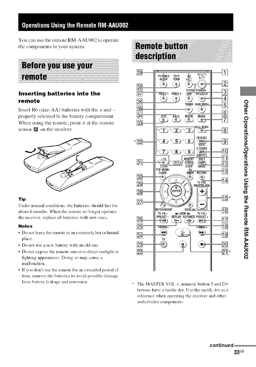
Inserting batteries into the
remote
Insert R6 (size-AA) batteries with tile + and -
properly oriented in tile battery compartment.
When using the remote, point it at the remote
Sellsor _ on tile receiver.
Tip
Under normal conditions, the batteries should last for
about 6 months. When the remote no longer operates
the receiver, replace all batteries with nex_ ones.
Notes
•Do not leave the remote in an extremely hot or humid
place.
•Do not use a new battery with an old one.
• Do not expose the remote sensor to direct sunlight or
lighting apparatuses. Doing so may cause a
malfunction.
• If you don't use the remote for an extended period of
time, remove the batteries to avoid possible damage
flom battery leakage and corrosion.
SYSTB_ STANDBY
O I VIDEO 2,_
,D, _. iE'_'_Td-
_ETURN/EXIT DIS
TVCH- _RISTEPIII_ TVDH+
PRESET- REPLAY ADVANCE PRESET+
÷
,--%
• The MASTER VOL +, numeric button 5 and 12>
buttons have a tactile (lot. Use the tactile dot as a
reference when operating tlle receiver and other
audio/; ideo components.
o
o
o
"o
-1
€"-
__.
al
o
3
o
t-
o
¢2a
continued
33G8
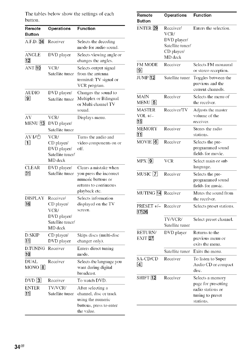
The tables below show the settings of each
button.
Remote Operations Function
Button
A.F.D. [] Receiver Selects Ihe decoding
mode for audio sound.
ANGLE DVD player Selects viewing angle or
[] changes tile angles.
ANT [] VCR/ Selects oulput signal
Satellite tuner from tile antenna
terminal: TV signal or
VCR program.
AUDIO DVD player/ Changes the sound to
[] Salellite luner Muhiplex or Bilingual
or Multi channel TV
sound.
AV VCR/ Displws menu.
MENU [] DVD player/
Satellite tuner
AV I/(_) VCR/ Turns the audio and
[] CD player/ video components oll or
DVD player/ off.
Satellite tuner/
MD deck
CLEAR DVD player/ Clears a mistake when
[] Salellite luner you press the incorrect
[//lllleric buttons or
returns to continuous
playback etc.
DISPLAY Receiver/ Selects information
[] CD player/ displayed on Ihe TV
VCR/ screen.
DVD player/
Satellite tuner/
MD deck
D.SKIP CD player/ Skips discs (multi-disc
[] DVD player changer only).
D.TUNING Receiver Enters direct tuning
[] mode.
DUAL Receiver Selects the lmlguage you
MONO [] want during digital
broadcast.
DVD [] Receiver To walch DVD.
ENTER TV/VCR/ After selecting a
[] Satellite tuner channel, disc or track
using the numeric
buttons, press to enter
the value.
Remote Operations Function
Button
ENTER [] Receiver/ Enters Ihe seleclion.
VCR/
DVD player/
Satellite tuner/
CD player/
MD deck
FM MODE Receiver Selects FM monaural
] or slereo receplion.
JUMP [] Salellite tuner Toggles between the
previous and the
c/irrent channels.
MAIN Receiver Selects the menu of
MEN U [] Ihe receiver.
MASTER Receiver/TV A(0usts the master
VOL +1 volume of the
] receiver.
MEMORY Receiver Stores the radio
[] slalions.
MOVIE [] Receiver Selects Ihe lyre-
programmed sou I1(1
fields for movie.
MPX [] VCR Selecl main or sub
language.
MUSIC [] Receiver Selects Ihe pre-
programmed sou 110
fields for music.
MUTING [] Receiver Mules the sound from
Ibe receiver.
PRESET +_ Receiver Selects preset station s.
TV/VCR/ Select preset channel.
Satellite tuner
RETURN/ DVD player Returns to the
EXIT [] previous menu or
exits the menu.
Satellite tuner Exits the menu.
SA-CD/CD Receiver To listen to Super
[] Audio CD or compacl
disc.
SHIFT [] Receiver Selecls a memory
page for presetting
radio stations or
tuning to preset
stations.
34 _
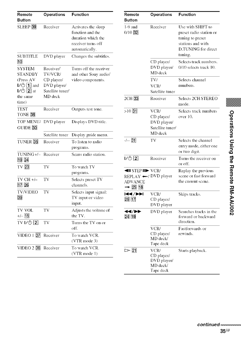
Remote Operations Function
Button
SLEEP [] Receiver Activates the sleep
fimction and the
duration which the
receiver turns off
automatically.
SUBTITLE DVD phlyer Changes the subtitles.
[]
SYSTEM Receiver/ Turns off the receiver
STANDBY TV/VCR/ and other Sony audio/
(Press AV CD player/ video components.
I/(_) [] and DVD phlyer/
I/(_ [] at Satellite tuner/
tile same MD deck
time)
TEST Receiver Outputs test tone.
TONE []
TOP MENU/ DVD phlyer Disphlys DVD title.
GUIDE []
Satellite tuner Disphly guide menu.
TUNER [] Receiver To listen to radio
programs.
TUNING+/ Receiver Scans radio station.
@[]
TV [] TV To watch TV
programs.
TV CH +_ TV Selects preset TV
[] [] channels.
TV/VIDEO TV Selects input signal:
[] TV input or video
input.
TV VOL TV A(liusts the volume of
+_ [] the TV.
TV I/(_) [] TV Turns the TV on or
off
VIDEO 1 [] Receiver To _atch VCR.
(VTR mode 3)
VIDEO 2 [] Receiver To _atch VCR.
(VTR mode I)
Remote Operations Function
Button
I-9 and Receiver
0/io [] Use wilh SHIFT to
presel radio station or
luning Io preset
slalions and wilh
D.TUNING for direct
luning.
CD player/ Selects track lmmbers.
DVD player/ 0110 selecls track 10.
MD deck
TV/ Selects channel
VCR/ numbers.
Satellite luner
2CH [] Receiver Selects 2CH STEREO
lIlode.
>10 [] VCR/ Selects track numbers O
CD player/ over 10.
DVD player/
Satellite luner/ _.
MD deck '_
-/-- [] TV Selects the channel €-'
entry mode, either one _.
or Iwo digit.
I/_ [] Receiver Turns the receiver on
or olT. ¢D
_lll STEP Ilil,,-VCR/ Replay Ihe pre;'ious
REPLAY *"/DVD phtyer scene or fasl forwaM :_
O
ADVANCE Ihe currenl scene.
•-[]@ zQ
/I_P't VCR/ Skips tracks.
[] [] CD player/ _,
DVD phtyer €-
(D
.4_ll/l_i- DVD phtyer Seal-ches Iracks in the _1_
[] [] R)rwaM or backward
direction.
VCR/ Fasl forwards or
CD player/ rewiMs.
MD deck/
Tape deck
[2> [] VCR/
CD player/
DVD pla? er/
MD deck/
Tape deck
Starls playback.
continued
35G8
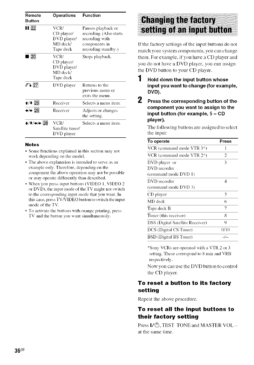
Remote Operations Function
Button
II [] VCR/ Pauses playback or
CD phLver/ recording. (Also starts
DVD player/ recording wilh
MD deck/ components in
Tape deck recording standby.)
• [] VCR/ Stops playback.
CD plwer/
DVD player/
MD deck/
Tape deck
0*%[] DVD player Returns to the
previous nlenu OF
exits tile menu.
t1.1!_[] Receiver Selects a menu item.
_.1. [] Receiver Adjusts or changes
the setting.
tI./tP,/_./,*.[] VCR/ Selects a menu item.
Satellite tuner/
DVD player
Notes
•Some fimctions explained in this section may not
work depending on the model.
• The above explanation is intended to serve as an
example only. Therefore, depending on the
component the above operation may not be possible
or may operate differently Ihan described.
• When you press input buttons (VIDEO 1, VIDEO 2
or DVD), the input mode of the TV might not switch
to the corresponding input mode that you want. In
this case, press TV/VIDEO button to sx_itch tile input
mode of the TV.
• To activate the buttons with orange printing, press
TV and tile button you want simultaneously.
If the lactory settings of the input buttons do not
match your system components, you can change
them. For example, if you have a CD player and
you do not have a DVD player, you can assign
the DVD butltm to your CD player.
1 Hold down the input button whose
input you want to change (for example,
DVD).
Press the corresponding button of the
component you want to assign to the
input button (for example, 5 - CD
player).
The lollowing buttons are assigned to select
the input:
To operate Press
VCR (command mode VTR 3') 1
VCR (command mode VTR 2') 2
DVD plwer or 3
DVD recorder
(command mode DVD 1)
DVD recorder 4
(command mode DVD 3)
CD plwer 5
MD deck 6
Tape deck B 7
Tuner (this receiver) 8
DSS (Digital Satellite Receiver) 9
DCS (Digital CS Tuner) 0/Ill
BSD (Digital BS Tuner) -/--
:'-SonyVCRsare operatedwilha VTR 2 or 3
setting.Thesecorrespondto 8 mmand VHS
respectively.
Nuw yuu can use the DVD button to control
the CD player.
To reset a button to its factory
setting
Repeat the abuve procedure.
To reset all the input buttons to
their factory setting
Press I/(_), TEST TONE and MASTER VOL -
at the same time.
36_
On safety
Should _my solid ol2[ect or liquid f:dl into the cabinet,
unplug the receiver and b; e it checked by qualified
personnel before operating it any fiulher.
On power sources
• Before operating the receiver, check that the
operating voltage is identical with your local power
supply. The operating voltage is indicated on the
nameplate at the rear of the receiver.
• The receiver is not disconnected from the AC power
source (mains) as long as it is connected to the wall
outlet, even if the receiver itself has been turned off.
• If you are not going to use the receiver for a long
time, be sure to disconnect the receiver from the wall
outlet. To disconnect the AC power cord, grasp the
plug itself: never pull the cord.
• (Models of area code U, CA only)
One blade of the plug is wider than the other lbr the
purpose of safely and will fit into the wall outlet only
one way. If you are u n_dqe to insell the plug fi]lly into
the outlet, contact your dealer.
• AC power cord mu st be changed only at the qualified
service shop.
On heat buildup
Although the receiver he,its u 1)during open_tion, tiffs is
not a malfimction. If you continuously use tiffs receiver
at a large volume, the cabinet temperature of the top,
side and bottom rises considerably. To _'_oid burning
yourself, do not touch the cabinet.
On placement
• Ph_ce the rect.dver in a location _ith adequate
ventilation to prevent heat buildup and prolong the
life of the receiver.
• Do not place the receiver near heat sources, or in a
place sul2iect to direct sunlight, excessive dust or
mechanical shock.
• Do not place anything on top of the cabinet that
might hlock the ventilation holes and cause
malfimctions.
• Use caution when placing the receiver or speakers on
surfaces that have been specially treated (with wax,
oil, polish, etc.) as staining or discoloration of the
surface 1l/3y result.
On operation
Belorc connecting other components, be sure to turn
off and unplug Ihe receiver.
If you encounter color irregularity on a
nearby TV screen
The front and center speakers and the sub wooer are
magnetically shielded to allow it to be installed near
a TV set. However, color irregularities may still be
observed on certain types of TV sets. As the surround
speakers are not magnetically shielded, x_e
recommend that you place the surround speakers
slightly further away from TV set (page I I ).
If color irregularity is observed...
Turn off the TV set once, then turn it on _gain _d_er
15 to 30 minutes.
If color irregularity is observed again...
Ph_ce the spe_ker further m_ _3' from the TV set.
If howling occurs
Reposition the speakers or turn down the volume on
the receiver.
On cleaning
Clean the cabinet, p_mel _md controls x_ith _ soft cloth
slightly moistened with a mild detergent solution. Do
not use any type of abrasive pad, scouring powder or
solvent such as alcohol or benzine.
If you h_x e any question or problem concerning your
receiver, please consult your nearest Sony dealer.
5"
a_
37G8
If you experience any of the lollowing
difliculties while using the receiver, use this
troubleshooting guide to help you remedy the
problem.
There is no sound or only a very low-level
sound no matter which component is
selected.
• Check that tile speakers and components are
connected securely and correctly.
• Check that both the receiver and all components
are t/irned on.
• Check that you have selected the correct
component on the receiver.
• Check that MASTER VOLUME _+ is not set at
"VOL MIN".
• Check that the headphones are not connected.
• Press MUTING on the remote to cancel the
muting l;mction.
There is no sound from a specific component.
• Check that the component is connected correctly
to the audio input jacks lbr that component.
• Check that the cord(s) used lbr the connection is
(are) fully inserted into Ihe jacks on both the
receiver and the component.
• Check that you have selected the correct
component on the receiver.
There is no sound from one of the front
speakers.
• Connect a pair of headphones to the PHONES
jack to verily' that sound is output from the
headphones. If only one channel is output from the
headphones, the component may not be connected
to the receiver correctly. Check that all the cords
are filly inserted into the jacks on both the
receiver and the component. [f both channels are
output from Ihe headphones, the fiont speaker
may not be connected to the receiver correctly.
Check the connection of the fiont speaker which is
not outputting any sound.
There is no sound from analog 2 channel
sources.
• Check that the INPUT MODE is not set to
"COAX IN" or "OPT IN" (page 28).
There is no sound from digital sources (from
COAXIAL or OPTICAL input jack).
• Check that the INPUT MODE is not set to
"ANALOG" (page 28). Check that the INPUT
MODE is not set to "COAX IN" lbr the sources
from OPTICAL input jack, or set to "OPT IN" for
the sources from COAXIAL input jack.
The left and right sounds are unbalanced or
reversed.
• Check that the speakers and components are
connected correctly and securely.
• Adjust balance parameters in the LEVEL menu.
There is severe hum or noise.
• Check that the speakers and components are
connected securely.
• Check that the connecting cords are away from a
transformer or motor, and at least 3 meters ax_ay
from a TV set or fluorescent light.
• Move your TV awW from the audio components.
• The phlgs and jacks are dirty. Wipe them _ith a
cloth slightly moistened with alcohol.
There is no sound or only a very low-level
sound is heard from the center or/and
surround speakers.
• Select a CINEMA STUDIO EX mode (page 26).
• Adjust the speaker level (page 17).
There is no sound from the sub woofer.
• Check that the sub _ool'cr is connected correctly
and securely.
The surround effect cannot be obtained.
• Make sure the sound field function is on (press
MOVIE or MUSIC).
• Sound fiekls do not fimction lbr the signals with a
sampling frequency of more than 48 kHz.
38_
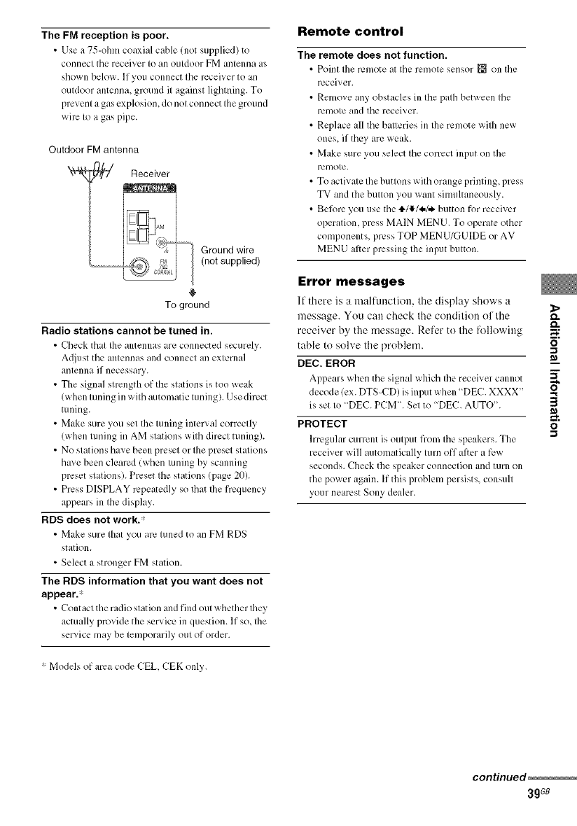
The FM reception is poor.
•Use a 75-ohm coaxial cable (not supplied) to
connect tile receiver to an outdoor FM antenna as
shown below. If you connect tile receiver to an
outdoor antenna, ground it against lighming. To
prevent a gas explosion, do not connect the ground
wire to a gas pipe.
Outdoor FM antenna
Receiver
Ground wire
(not supplied)
To ground
Radio stations cannot be tuned in.
•Check that the antennas are connected securely.
A(liust tile antennas and connect an external
antenna if necessary.
• The signal strength of the stations is too weak
(when tuning in with automatic tuning). Use direct
tuning.
• Make sure you set the tuning interx al correctly
(when tuning in AM stations with direct tuning).
• No stations have been preset or the preset stations
ha; e been cleared (when tuning by scanning
preset stations). Preset the stations (page 211).
• Press DISPLAY repeatedly so that the frequency
appears in the display.
RDS does not work.'
•Make sure that you are tuned to an FM RDS
station.
• Select a stronger FM station.
The RDS information that you want does not
appear?
• Contact the radio stat ion and find out _qlether they
actually provide the service in question. If so, the
service may be temporarily out of order.
• Models of area code CEL CEK only.
Remote control
The remote does not function.
Point the remote at the remote sensor _{_on Ihe
receiver.
Remove any obstacles in tile path between the
remote and tile receiver.
Replace all tile batteries in the remote with new
ones, if they are weak.
Make sure you select the correct input on the
remote.
To activate the buttons with orange printing, press
TV and the button you want simultaneously.
Before you use the tl,/tF/_./_ button for receiver
operation, press MAIN MEN U. To operate other
components, press TOP MENUYGUIDE or AV
MENU after pressing the input button.
Error messages
11there is u malfunclion, lhe display shows u _>
message. You can check the condition of the o.
receiver by the message. Refer to the lk)llowing _;
table to solve the problem. _"
DEC. EROR
Appears when tile signal which file receiver cannot _"
decode (ex. DTS-CD) is input when "DEC. XXXX"
is set to "DEC. PCM'. Set to "DEC. AUTO".
PROTECT _"
.-t
Irregular current is output from the speakers. The
receiver will automatically turn off after a few
seconds. Check the speaker connection and turn on
the power again. If this problem persists, consult
your nearest Sony dealer.
continued
3gGB
If you are unable to remedy the
problem using the
troubleshooting guide
Clearing the receiver's memory may remedy the
problem (page 14). However, note that all
memorized settings will be reset to their lactory
settings and you will have to readjust all settings
Oil the receiver.
If the problem persist
Consult your nearest Sony dealer.
Reference sections for clearing
the receiver's memory
To clear See
All memorized settings page 14
Customized sound fields page 29
AUDIO POWER SPECIFICATIONS
POWER OUTPUT AND TOTAL HARMONIC
DISTORTION:
(Models of area code U only)
With 6 ohm loads, both channels driven, fi'om
120 20,000 Hz; rated 60 watts per channel
minimum RMS power, with no more than 0.7_7_
total harmonic distortion from 250 milliwatts to
rated output.
Amplifier section
Power Output I)
Models of area code U
16 ohms 1 kHz, THD 10%)
FRONT2): I/)O W/ch
CENTER2): l/)0 W
SURR2): l/)0 W/ch
(6 ohms 100 Hz, THD 10(); )
SUB WOOFER2i: I/)0 W
Models of area code CA
16 ohms 1 kHz, THD 0.7%)
FRONT2): 60 W/ch
CENTER2): 60 W
SURR2): 60 W/ch
(6 ohms 100 Hz, THD 0.7%)
SUB WOOFER2): 60 W
16 ohms 1 kHz, THD 10G)
FRONT2): I//0 W/ch
CENTER2): I//0 W
SURR2): 100 W/ch
16 ohms 100 Hz, THD 10c);)
SUB WOOFER2I: I//O W
Models of area code MX, SP, E51, CEL. CEK
(6 ohms 1 kHz, THD/).7c); )
IFRONT2): 50 W/ch
CENTER2): 50 W
SURR2i: 50 W/ch
16 ohms 100 Hz, THD 0.7qt )
SUB WOOFER2I: 50 W
16 ohms l kHz, THD I/)q)
IFRONT2): 85 W/ch
CENTER2!: 85 W
SURR2): 85 W/ch
16 ohms 100 Hz, THD 10c);)
SUB WOOFER2i: 85 W
40_
Models of area code AU
(6 ohms 120 Hz 20 kHz, THD 11.09%)
FRONT2): 40 W/ch
CENTER2>: 4(}W
SURR2): 40 W/ch
(6 ohms 100 Hz, THD 0.09c7_)
SUB WOOFER2): 40 W
(6 ohms 1kHz, THD 11.7c7_)
PRONT2I: 50 W/ch
CENTER2I: 50 W
SURR2): 5(1W/ch
(6 ohms 100 Hz, THD//.7c)k)
SUB WOOFER2>: 50 W
(6 ohms 1kHz, THD 10%)
FRONT2): 85 W/ch
CENTER2): 85 W
SURR2): 85 W/ch
(6 ohms 100 Hz, THD 10%)
SUB WOOFER2): 85 W
I) Measured under the lbllowing conditions:
Area code Power requirements
U, CA 120 V AC, 60 Hz
CEL, CEK, SP 230 V AC, 50 Hz
AU, E51 240 V AC, 50 Hz
MX 127 V AC, 60 Hz
2) Depending on the sound field settings and tile
source, there [iiHybe no sound outptlt.
Inputs (Analog)
SA-CD/CD, DVD, Sensitivity: 8(}(}mV
VIDEO 1,2 hnpedance: 50 k ohms
Inputs (Digital)
DVD (Coaxial) Sensitivity:
hnpedance: 75 ohms
SA-CD/CD (Optical) Sensitivity:
hnpedance:
Output (Analog)
SUB WOOFER Voltage: 2 V
hnpedance: 1 k ohm
Reproduction frequency range:
28 20,1)00 Hz
Tone
Gain levels -+6dB, I dB step
FM tuner section
Tuning range 87.5 - 11)8.0MHz
Antenna FM wire antenna
Antenna terminals 75 ohms, unbalanced
h_termediate frequency 10.7 MHz
AM tuner section
Tuning range
Models of area code U, CA
Wilh 10-kHz luning scale: 53(1 1,710 kHz _)
Wilh 9-kHz luning scale: 531 1,710 kHz ?)
Models of area code CEL, CEK, AU, SP
With 9-kHz tuning scale: 531 1,602 kHz
Model of area code E51
Wilh 10-kHz luning scale: 53(1 1,610 kHz:_)
Wilh 9-kHz luning scale: 531 1,602 kHz3)
Models of area code MX
Wilh 10-kHz tuning scale: 530 1,610 kHz
Antenna Loop antenna
Intermediate fiequency 45() kHz
3) You can change the AM tuning scale to 9 kHz or _.
10kHz. After tuning in any AM station, turn off the
receiver. While holding down PRESET TUNING + O"
or TUNING +, press I/(_). All preset stalions will be m_
erased when you change Ihe tuning scale. To reset _.
the scale to Il)kHz (or 9 kHz), repeat the procedure.
General
Po_ er req/lilements
Area code Power requirements
U, CA 12()V AC, 60 Hz
CEIL,CEK 230 V AC, 50160 Hz
AU 24(1V AC, 5(1Hz
E51 1201221)1241)V AC,
50160 Hz
SP 220-230 V AC, 511160Hz
MX 127 V AC, 60 Hz
Power consumption
Area code Power consumption
U, SP, E51, AU, CEL, 160 W
CEK, MX
CA 220 VA
B"
continued
41GB
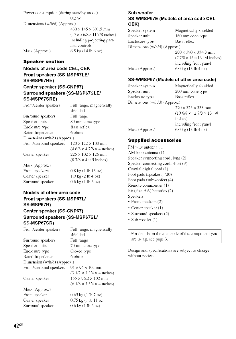
Power consumption (during standby mode)
0.2 W
Dimensions (_/h/d) (Approx.)
43() x 145 x 301.5 mm
117 x 5 618 x 11 718 inches/
including prqjecting parts
and controls
Mass (Approx.) 6.5 kg (14 lb 6 oz)
Speaker section
Models of area code CEL, CEK
Front speakers (SS-MSP67LE/
SS-MSP67RE)
Center speaker (SS-CNP87)
Surround speakers (SS-MSP67SLE/
SS-MSP67SRE)
Front/center speakers Full range, magnetically
shielded
Surround speakers Full range
Speaker units 80 mm cone type
Enclosure lype Bass reflex
Rated hnpedance 6 ohms
Dimension (w/h/d) (Approx.)
Front/surround speakers 121)x 122 x loll mm
Center speaker
14 6/8 x 4 7/8 x 4 inches)
225 x 102 x 126 mm
18 7/8 x 4 x 5 inches)
Mass (Approx.)
Front speakers 0.8 kg (1 lb 13 oz)
Center speaker 1.0 kg (2 lb 4 oz)
Surround speaker 1).6kg (1 lb 6 oz)
Models of other area code
Front speakers (SS-MSP67L/
SS-MSP67R)
Center speaker (SS-CNP67)
Surround speakers (SS-MSP67SL/
SS-MSP67SR)
Front/center speakers Full range, magnetically
shielded
Surround speakers Full range
Speaker units 70 mm cone type
Enclosure lype Closed lype
Rated hnpedance 6 ohms
Dimension (w/b/d) (Approx.)
Front/surround speakers 91 x 96 x 102 mm
13 I12 x 3 3/4 x 4 inches)
Center speaker 155 x 96.2 x 102 mm
16 I/8 x 3 3/4 x 4 inches)
Mass (Approx.)
Front speaker 0.65 kg (1 lb 7 oz)
Center speaker 0.75 kg (1 lb II oz/
Surround speaker 0.6 kg (1 Ib 6 oz)
Sub woofer
SS-WMSP67E (Models of area code CEL,
CEK)
Speaker system Magnetic:ally shieMed
Speaker unit 160 mm cone lype
Enclosure lype Bass reflex
Dimensions (w/b/d) (Approx.)
200 x 38(1x 334.3 mm
(7 7/8 x 15 x 13 I/4 inches)
including front panel
Mass (Approx.) 6.(1kg (13 lb 4 oz)
SS-WMSP67 (Models of other area code)
Speaker system Magnetically shielded
Speaker unit 200 mm cone lype
Enclosure lype Bass reflex
Dimensions (w/h/d) (Approx.)
270 x 325 x 333 mm
(106/8 x 127/8 x 13 I/8
inches)
including front panel
Mass (Approx.) 6.0 kg (13 lb 4 oz)
Supplied accessories
FM wire antenna (1)
AM loop antenna (1)
Speaker connecting cord, long (2)
Speaker connecting cord, short (3)
Coaxial digital cord (1)
Foot pads (speakers) (20)
Foot pads (subwoofer) (4)
Remote commander (1)
R6 (size-AA) batteries (2)
Speakers
•Front speakers (2)
• Center speaker (1)
• Surround speakers (2)
•Sub woofer (I)
For details on the area code of the componenl you
are using, see page 3.
Design and specifications are sul2ject to change
without notice.
42_
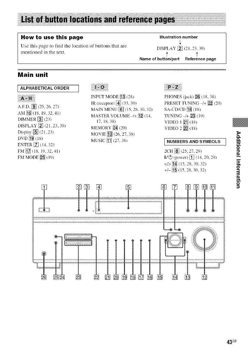
How to use this page Illustration number
Use this page to find the location of buttons thai are DISPLAY [] (21,23, 39)
mentioned in the text. ,],
Name of button/part Reference page
Main unit
ALPHABETICAL ORDER
A.F.D. [] (25, 26, 27)
AM [] (18, 19, 32, 41)
DIMMER [] 123)
DISPLAY []/21,23 39)
Display [] (21,23)
DVD [] (18)
ENTER [] (14, 321
FM [] (18, 19, 32,41)
FM MODE [] (19)
INPUT MODE [] (28)
IR (receptor) [] (33, 39)
MAIN MENU [] ( 15, 28, 30, 32)
MASTER VOLUME _+ [] (14,
17, 18, 38)
MEMORY [] (20)
MOVIE [] (26, 27, 38)
MUSIC [] (27, 38)
PHONES (.jack) [] (18, 38)
PRESET TUNING /+ [] (20)
SA-CD/CD [] (18)
TUNING l+ [] (19)
VIDEO 1 [_ (18)
VIDEO 2 [] (18)
I NUMBERS AND SYMBOLS I 5"
2CH [] (25, 27, 29) "_
I/@ (power) []/14 2(} 29) _--"
<1>[_(15 28 30 32)
+/ [] (15, 28, 30, 32)
43G8
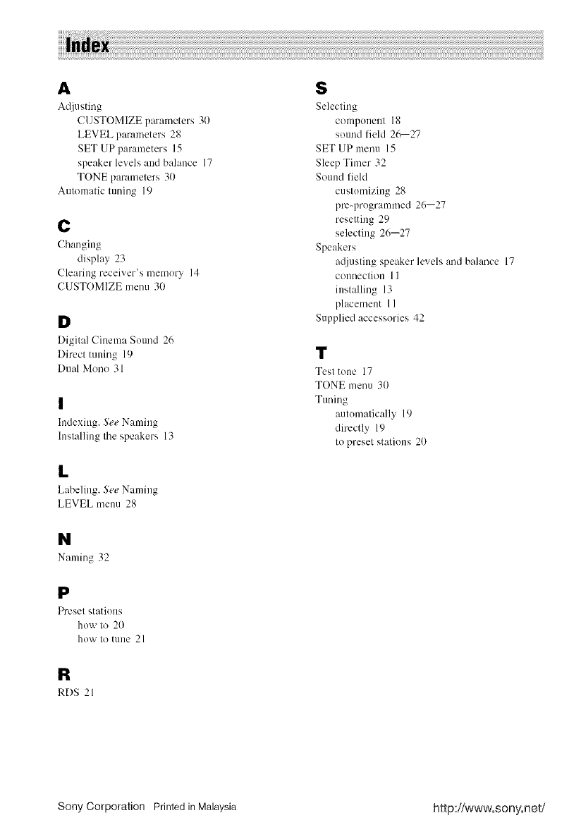
A $
Adjusting Selecting
CUSTOMIZE parameters 31) compenent 18
LEVEL parameters 28 sound lield 26--27
SET UP parameters 15 SET UP menu 15
speaker levels and balance 17 Sleep Timer 32
TONE parameters 30 Sound fieM
Automatic tuning 19 custemizing 28
pm-pregrammed 26--27
reselting 29
C selecting 26--27
Changing Speakers
display 23 atljusting speaker levels and balance 17
Clearing receiver's memory 14 connection 11
CUSTOMIZE menu 30 installing 13
placement 11
D Supplied accessories 42
Digital Cinema Sound 26
Direct tuning 19 "1_
Dual Mono 31 Test tone 17
TONE menu 30
Tuning
autematically 19
directly 19
to preset stations 20
I
Indexing. See Naming
Inslalling Ihe speakers 13
L
Labeling. See Naming
LEVEL menu 28
N
Naming 32
P
Presel statiens
how to 20
how Io mne 21
R
RDS 21
Sony Corporation Printed in Malaysia http://www.sony.net/
