Sony PCWA A100 User Manual Access Point Help File PCWAA100 APguide
User Manual: Sony PCWA-A100 Access Point Help File
Open the PDF directly: View PDF ![]() .
.
Page Count: 61

Getting started
You can build a Wireless LAN environment that connects up to 49 computers (a maximum 16 is recommended) by connecting the Wireless
LAN Access Point PCWA-A100 (called the Access Point below) a computer in which the Wireless LAN PC Card PCWA-C100 is inserted.
While enabling the sharing of files between all computers connected over the same Wireless LAN, it is also possible for multiple of computers
within the same LAN system to connect to the Internet, if the Access Point is connected to a telephone line, an ISDN router, cable modem or to
an xDSL modem. Furthermore, you can build a Wireless LAN environment between computers that are installed with the Wireless LAN PC Card
without having to use the Access Point. (This is called peer-to-peer connection.)
Note
For best results in viewing this help file, use Microsoft Internet Explorer 5 or later. Some graphics may not display properly if you are using an
earlier version.
Page 1

Wireless LAN Utilities
There are four types of softw are in the Wireless LAN Utilities. They are described below .
Wireless Pale tte
This is the softw are that displays the status of communications betw een the computer mounted w ith the Wireless LAN PC Card and the Access Point. If there are
multiple Access Points, you can use it to sw itch the Access Point connection. Normally, it displays the status of communications in the status area of the taskbar.
Bas ic Access Point Setup Utility
This is the softw are to set the Access Point to connect to the Internet. The basic settings for connection are completed w hen using this softw are.
Custom Access Point Setup Utility
This is the softw are for making detailed settings for the Access Point. You can also make detailed settings for Internet connections.
Access Point Firm w are Upgrade Utility
This is the softw are for updateing Access Point firmw are.
If the Access Point Setup Utility and Access Point firmw are versions is incompatible, update the Wireless LAN Utilities, or update the Access Point firmw are.
Refer here for details on checking and updating versions.
Note
If you are using Window s 2000, there are restrictions to user rights. See Privileges of Window s 2000 Users for details.
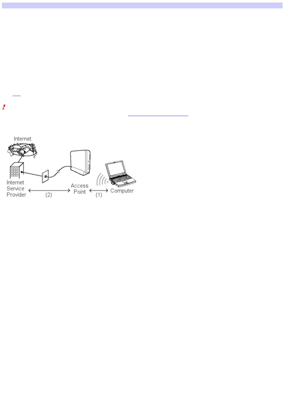
Roles of the Wireless Palette and the Access Point Setup Utilities
(1) Use the Wireless Palette to make settings required for communications betw een the computer and the Access Point.
(2) Use the Basic Access Point Setup Utility or the Custom Access Point Setup Utility to make settings required for connection betw een the Access Point and the
Internet Service Provider (ISP). The utility must be used on one of the computers on the w ireless LAN.
Page 3

The setup process
The setup process w ill vary depending on the w hether or not your Access Point and Wireless LAN PC Card have been used. Refer to the Wireless LAN PC Card
Operating Instructions for details.
Note
Using an Access Point Setup Utility prior to version 2.0.1 to set to an Access Point w hose firmw are version is later than 3.7 and w ill result in abnormal operation.
Before using your existing Access Point Setup Utility, confirm the Access Point Setup Utility version and the Access Point firmw are version to update them as
necessary.
Refer here for details on checking and updating the version.
Flow of settings
If the Access Point has not been used:
Connect the Access Point to a pow er source.
Refer to the Wireless LAN Access Point Operating Instructions for details.
If the Wireless LAN PC Card has not been used:
1. Insert the Wirele ss LAN PC Card into your com puter.
2. Install the Wireles s LAN PC Card driver.
Note
If you are using a computer that has multiple Ethernet interfaces, you must stop using an Ethernet interface other than the Wireless LAN PC Card.
Refer to When using a computer that has an Ethernet interface other than the Wireless LAN PC Card for details.
3. Setup the Window s-based environment.
Refer to the Wireless LAN PC Card Operating Instructions for details.
4. Install the acce ssory software.
Refer to the Wireless LAN Access Point Operating Instructions for details.
Register the Access Point to the Wireless Palette for each computer connected to the Wireless LAN.
Refer to the Wireless LAN PC Card Operating Instructions for details.
Make the settings for the Access Point using the Basic Access Point Setup Utility.
Refer to the Wireless LAN PC Card Operating Instructions for details.
Hint
You can make detailed settings for the Access Point if you use the Custom Access Point Setup Utility.
Page 4


Check the version
Us ing an Access Point Setup Utility prior to version 2.0.1 to set to an Access Point w hose firmw are version is later than 3.7 w ill result in
abnormal operation. Before using your existing Access Point Setup Utility, alw ays confirm the follow ing:
The version of the Access Point Setup Utility.
The firmw are version of the Access Point.
Checking the Access Point Setup Utility version
1. From the Start m enu, sele ct VAIO, Wireless LAN, then Custom Access Point Setup Utility or Basic Access Point Setup Utility.
Either the Custom Access Point Setup Utility or the Basic Access Point Setup Utility starts.
2. Check the version that is displayed in the title bar.
Checking the Access Point firmware version
1. Right-click the Wireles s Palette in the status area of the taskbar.
2. Sele ct the Version from the m enu that is displayed.
If the combination of the Access Point Setup Utility and Access Point firmw are versions is incompatible, update the Wireless LAN Utilities, or update the Access
Point firmw are.
From the Start menu, select VAIO, Wireless LAN, Access Point Firmw are Upgrade, then Manual. Refer to the Upgrade Utility Help file for details.
Page 6

When using a computer that has an Ethernet interface other than the Wireless LAN PC Card
When using the Wireless LAN PC Card, you must stop the use of Ethernet interfaces other than the Wireless LAN PC Card.
When running the Window s 98 Second Edition
When running the Window s Me
When running the Window s 2000
When running the Windows 98 Second Edition:
1. From the Start m enu, sele ct Settings, then Control Panel.
2. Double-click System .
3. Sele ct the De vice Manager tab and then double-click Ne tw ork adapters.
4. Double-click the netw ork adapter that you w ant to stop.
5. Sele ct the check box for "Disable in this Hardw are Profile" in the dialog box that is displayed, then click OK.
An "X" w ill appear for the device that has been stopped.
6. Click OK.
The System Properties dialog box closes.
When running the Windows Me:
1. From the Start m enu, sele ct Settings, then Control Panel.
2. Double-click System . (If all of the control panel options are not displayed, click "vie w all Control Panel Options", then double-click
System .)
3. Sele ct the De vice Manager tab and double-click Ne tw ork adapters.
4. Double-click the netw ork adapter that you w ant to stop.
5. Sele ct the check box for "Disable in this Hardw are Profile" in the dialog box that is displayed, then click OK.
An "X" w ill appear for the device that has been stopped.
6. Click OK.
The System Properties dialog box closes.
When running the Windows 2000:
1. From the Start m enu, sele ct Settings, then Control Panel.
2. Double-click System .
3. Sele ct the Hardw are tab and then click the De vice M anager.
The Device Manager w indow is displayed.
4. Double-click Ne tw ork adapters.
5. Double-click the netw ork adapter that you w ant to stop.
6. Sele ct "Do not use this device (disable)" from the De vice usage drop-dow n m enu, then click OK.
An "X" w ill appear for the device that has been stopped.
7. Click .
The Device Manager w indow closes.
Page 7

Privileges of Windows 2000 users
With Window s 2000, functions that can be performed depend on the user's privilege level.
Privilege LevelFunction
Administrators Installation of driver: Yes
Installation of Wireless LAN Utilities: Yes
Execution of Wireless LAN Utilities: Yes
Pow er Users
(Standard users) Installation of driver: Yes
Installation of Wireless LAN Utilities: Yes
Execution of Wireless LAN Utilities: Yes w ith restrictions *1
Users
(Restricted users) Installation of driver: No
Installation of Wireless LAN Utilities: No
Execution of Wireless LAN Utilities: Yes w ith restrictions *2
*1
Registration of the Access Point is not possible with the Wireless Palette.
Even if the Encryption Key is changed with the Access Point Setup Utility, that setting is not reflected at the client.
*2
You can only check the electric wave status with the Wireless Palette.
You cannot run the Basic Access Point Setup Utility or the Custom Access Point Setup Utility.
Page 8

Configuring the Access Point
Note
Before configuring the Access Point, do the follow ing:
1. Connect the Access Point to a pow er source.
Refer to the Wireless LAN Access Point Operating Instructions for details.
2. Insert the Wirele ss LAN PC Card, and install the driver and other software supplied w ith the Wirele ss LAN PC Card to your com puter.
Refer to the Wireless LAN PC Card Operating Instructions manual for details.
3. Establish a connection to the Access Point using the Wireles s Palette.
Refer to the Wireless LAN PC Card Operating Instructions manual for details.
Follow the task sequence below to configure the Access Point using the Custom Setup Utility.
1. Proceed to Loading the Acce ss Point configuration to load the current configuration from the Access Point.
2. Proceed to Se tting comm on param eters to specify com m on parameters.
3. Proceed to Se tting mode-dependent param eters to specify m ode-dependent parameters. [Keyw ord] Configuring the Wireles s LAN
Access Point Configuring the Access Point
Page 9

Loading the Access Point configuration
Select the Access Point you w ant to configure to load its configuration. Make sure your computer can communicate w ith the Access Point using the Wireless
Palette. You may also load the configuration file stored in the hard disk.
1. Click the Start button on the task bar.
The Start menu appears.
2. From the Start m enu, sele ct VAIO, Wireless LAN, then Custom Access Point Setup Utility.
The Custom Access Point Setup Utility appears.
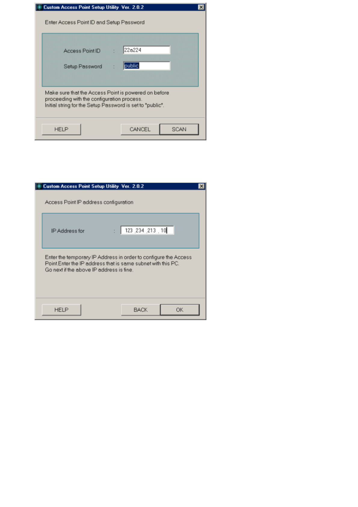
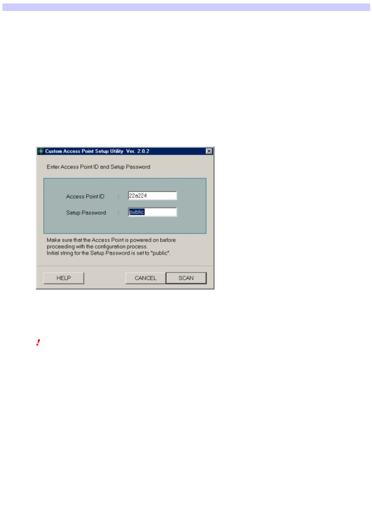
3. Verify that the ID displayed in the Access Point ID box is the sam e as the Access Point ID that you w ant to set, then enter the passw ord
for setting the access point in the Pass w ord box and click SCAN.
The passw ord box contains the initial value "public". The Access Point ID is a six-digit number on the label attached on the bottom of the Access Point unit. If
the Access Point ID displayed is different from the one on the label, enter the correct ID.
Note
If an error message appears, click OK.
Verify the follow ing and repeat step 2.
oThe Wireless LAN PC Card is inserted in your computer.
oThe Wireless LAN PC Card driver is installed.
oThe Access Point is pow ered.
oThe Access Point ID is the same as the one displayed.
oThe passw ord is correct.
oThe Wireless LAN PC Card and the Access Point are placed close enough to communicate w ith each other (w ithin approximately 100 m (330 feet)).
oThe Wireless Palette displays the communication status to the Access Point.
Forgot your password?
You can check your passw ord using the follow ing steps if it w as changed after you uploaded the settings.
oUse the Explorer to open the folder to w hich the Access Point Setup Utility w as installed (normally it is: C:\Program
Files \Sony\Wireles sLAN) on the com puter to w hich the Access Point Setup Utility w as se t.
oWith a text editor such as Notepad, open the file of the filenam e calle d "Access Point ID+conf" to w hich you tried to connect.
If the Access Point ID is "22a224", the filename w ill be "22a224conf". The Access Point ID and passw ord are listed in that file. Input the passw ord that you
confirmed into the Access Point Setup Utility startup screen.
How ever, the Encryption Key is not saved. If "-------" is displayed in the Encryption Key item, it means that that Encryption Key has not been changed since
the last time.
Also, you can return the passw ord setting to its original status (unset) by resetting the softw are. Read Reset mode and Softw are Reset mode for details on
how to reset the softw are.
Hint
You may also click LOAD to load the configuration file from the hard disk. How ever, you must enter the Encryption Key again because it is not saved.
Communication betw een the Access Point and the Wireless LAN PC Card begins and the "Selection of connection mode and setup of common parameters"
dialog box appears. Proceed to Setting common parameters and to Setting mode-dependent parameters.
Page 10
Page 11

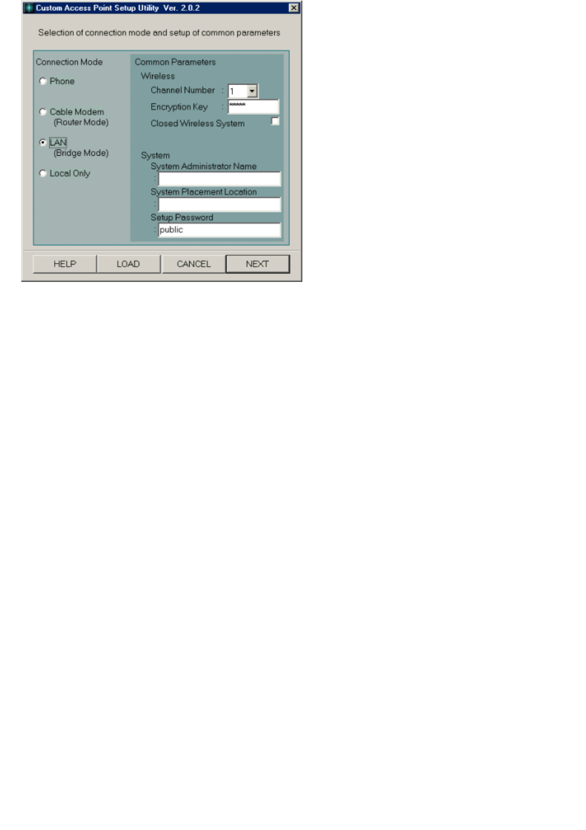
Setting common parameters
Specify the common parameters required for building a w ireless LAN (Local Area Netw ork).
This dialog box includes the follow ing parameters. When you are done, go to Setting mode-dependent parameters.
Channel Number
Select a channel number (1 through 11) from the drop-dow n menu.
Note
Assign a unique channel to each Access Point. If an error occurs due to the close proximity of another w ireless LAN or Access Point, try another
channel.
Encryption Key
You may encrypt w ireless communications to protect against unauthorized reception. Enter any five alphanumeric characters to set the Encryption Key.
Notes
Write dow n the Encryption Key and keep it in a secure location.
The last five digits of the Access Point ID are set as the initial value for the Encryption Key. We strongly recommend that you change this to
prevent unw arranted use from an outside party.
Closed Wireless System
Check this option to shield the Access Point from computers on other w ireless LANs.
System Administrator Name
Enter the name of your system administrator. You may enter up to 63 alphanumeric characters including symbols.
Hint
System Administrator may be left blank.
System Placement Location
Enter a location for your system. You may enter up to 127 alphanumeric characters including symbols.
Hint
System Placement Location may be left blank.
Setup Passw ord
You can use the passw ord for setting the Access Point for each Access Point. You can enter a maximum of 31 English characters and symbols (ASCII
characters). "public" is input as the initial value.
Note
We strongly recommend that you change the passw ord to prevent settings changes by an outside party. Make a note of the passw ord to w hich you
change so that you w ill not forget it.
Page 12

Setting mode-dependent parameters
Select a destination to specify the connection mode you w ant to use, then specify parameters specific to the connection mode of your choice.
Select a destination from Connection Mode and click NEXT. The w indow that appears depends on your selection.
Phone
Select this option to connect the Access Point to the telephone line.
For further steps, proceed to Setting up dial-up connection.
Cable Modem (Router Mode)
Select this option to connect the Access Point to the cable or xDSL modem.
For further steps, proceed to Setting up cable connection.
LAN (Bridge Mode)
Select this option to connect the Access Point to the ISDN router. This mode is also recommended for connecting the Access Point to the existing LAN,
such as the corporate LAN. Consult your netw ork administrator to identify the correct connection mode.
For further information on the operation, proceed to Setting up ISDN connection.
Local Only
Select this option for standalone use of the Access Point, w hen you do not w ant to connect it to any external w ired netw ork such as the Internet.
For further information, proceed to Setting up local connection.
Page 13
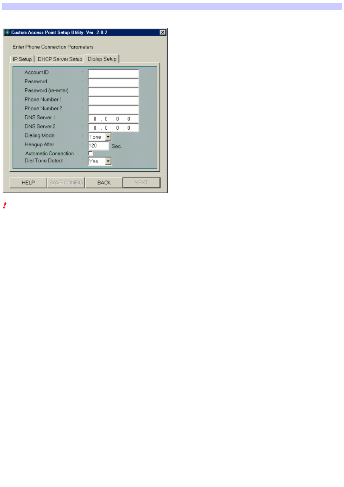
Setting up dial-up connection
Selecting Phone for Connection Mode in Setting mode-dependent parameters displays the Enter Phone Connection Parameters dialog box.
Notes
In the Phone mode, the Access Point serves as the DHCP server for both Ethernet and w ireless netw orks.
Never connect the Access Point in the Phone mode to any existing Ethernet netw ork w ith the DHCP server.
Consult w ith your netw ork administrator before connecting the Access Point to the existing Ethernet netw ork.
1. Click the Dialup Se tup tab.
This dialog box is for assigning functions to the Access Point for dialing up the ISP.
Account ID
Enter the account ID for connecting to the ISP.
Passw ord
Enter the passw ord for connecting to the ISP.
Passw ord (re-enter)
Enter the passw ord for connecting to the ISP once again.
Phone Number 1
Enter the telephone number of the ISP.
Phone Number 2
Enter the alternate telephone number to use w hen a call to Phone Number 1 is not completed.
(This item does not necessarily need to be entered.)
DNS Server 1
Enter the primary DNS server address if the ISP provides it.
DNS Server 2
Enter the secondary DNS server address if the ISP provides it.
Dialing Mode
Specify the telephone line type. Select Tone or Pulse.
Hangup After
Enter the length of time you w ant to allow for inactive communication before hanging up. You may specify up to 2550 seconds (42 minutes and 30
seconds) in units of 10 seconds. The factory default setting is 120 seconds (2 minutes).
Automatic Connection
Check this option to configure the Access Point to automatically make a dial-up attempt w hen connection to the Internet is needed. Page 14

Notes
oIf Automatic Connection is checked, an intentional connection attempt may be made depending on the computer settings.
oThe dial-up connection takes some time to be established, which may cause a time-out message depending on your e-mail
or browser application. If a time-out message appears, try sending/receiving mail or reloading the Web page again.
oNote that automatic disconnection may not work due to unexpected packets sent from the Internet. Click Disconnect to
disconnect the connection when you are through with the Internet access.
Dial Tone Detect
When you select "Yes", it waits for the dial tone of the telephone line to connect the dial-up.
Note
To hear the tone signal when you lift the telephone receiver, select "Yes", and select "No" not to hear the dial tone.
2. Click the IP Setup tab.
This dialog box is for assigning an IP address to the Access Point.
Hint
The Local IP Address and Local Subnet Mask are assigned by default. There is no need to change them.
Local IP Address
Enter the IP address of the Access Point.
Local Subnet Mask
Enter the subnet mask of the Access Point.
3. Click the DHCP Server Setup tab.
This dialog box is for specifying functions of the Access Point acting as the local DHCP (Dynamic Host Configuration Protocol) server.
Size of IP Address Pool
Enter the number of IP addresses that the DHCP server holds. This number should be larger than the number of clients
(computers) in your wireless LAN. In most cases, enter the recommended maximum number of clients (16).
You may specify up to 49 clients. The access speed declines as more clients are added to the LAN.
Lease Time
Enter the valid time period of IP addresses assigned by the DHCP server. You may specify up to 720 minutes.
Hint
To save the parameters you have entered the Access Point configuration file on the hard disk, click SAVE CONFIG.
The file may be loaded by clicking LOAD on the "Selection of connection mode and setup of common parameters" dialog box. See
Loading the Access Point configuration.
4. Click NEXT.
A screen appears asking you to confirm the mode you have selected.
5. Click UPLOAD.
The configuration you have made is registered in the Access Point.
Note
If an error message appears, re-enter the correct data.
6. When the Wireless Access Point Setup - Finish Screen appears, wait about 30 seconds.
Note
The link test is disabled for 30 seconds after the configuration is uploaded because the Access Point is automatically restarted.
You may start the link test when the Power indicator on the Access Point turns green.
7. Click LINK TEST. Page 15

The link test between the Access Point and the client is performed using your new configuration.
8. Click FINISH when the message "Link established with Access Point" is displayed.
The Custom Setup Utility closes.
Note
If an error message appears, open the Custom Access Point Setup Utility and check the configuration.
Page 16
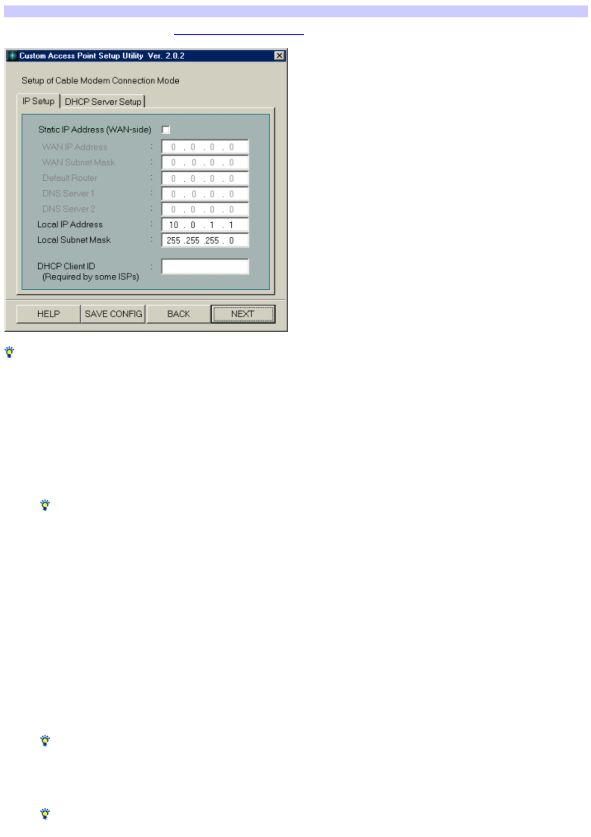
Setting up cable connection
Selecting Cable Modem for Connection Mode in Setting mode-dependent parameters displays the Setup of Cable Modem Connection Mode dialog box.
Hints
The Access Point acts as a NAT router w hen Cable Modem is selected for Connection Mode.
Select this mode w hen connecting the Access Point to a DSL modem if your DSL provider does not use PPPoE for connection.
1. Click the IP Se tup tab.
This dialog box is for entering the information required for configuring a WAN (Wide Area Netw ork) and assigning local IP addresses.
Static IP Address (WAN-side)
Check this option if the IP address to be used on the computer is specified in your cable modem contract, then fill in the follow ing fields.
If this option is left unchecked, the IP address is automatically assigned w hen connection to the ISP is established.
Hint
Ask your ISP (cable TV company) for more information.
WAN IP Address
Enter the IP address of the WAN.
WAN Subnet Mask
Enter the subnet mask of the WAN.
Default Router
Enter the IP address of the default router.
DNS Server 1
Enter the primary DNS server address.
DNS Server 2
Enter the secondary DNS server address.
Local IP Address
Enter the IP address of the LAN.
Hint
The Local IP Address is assigned by default. There is no particular need to change them.
Local Subnet Mask
Enter the subnet mask of the LAN.
Hint
The Subnet Mask is assigned by default. There is no particular need to change them.
Page 17

DHCP Client ID (Required by some ISPs)
With some cable operators, an identifier called a DHCP Client ID w ill be requested upon IP address acquisition by the client. In these cases, type the ID
specified from the cable operator. You may enter up to 63 alphanumeric characters including symbols.
Hint
When you directly connect your computer to a cable modem, enter the DHCP Client ID in the Computer name text box of the Window s Netw ork dialog
box.
2. Click the DHCP Se rver Setup tab.
This dialog box is for specifying functions of the Access Point acting as the DHCP server for the w ireless LAN.
Size of IP Address Pool
Enter the number of IP addresses that the DHCP server holds. This number should be larger than the number of clients (computers) in your w ireless
LAN. Normally, enter the recommended maximum number of clients, 16.
You may specify up to 49 clients. The more clients you specify, how ever, the more the access speed tends to decline.
Lease Time
Enter the valid time period of IP addresses assigned by the DHCP server. You may specify up to 720 minutes.
Hint
To save the parameters you have entered the Access Point configuration file on the hard disk, click SAVE CONFIG.
The file may be loaded by clicking LOAD on the "Selection of connection mode and setup of common parameters" dialog box. See Loading the Access
Point configuration.
3. Click NEXT.
A screen appears asking you to confirm the mode you have selected.
4. Click UPLOAD.
The configuration you have made is registered in the Access Point.
Note
If an error message appears, re-enter the correct data.
5. When the Wireless Access Point Setup - Finish Screen appears, w ait about 30 seconds.
Note
The link test is disabled for 30 seconds after the configuration is uploaded because the Access Point is automatically restarted.
You may start the link test w hen the Pow er indicator on the Access Point turns green.
6. Click LINK TEST.
The link test betw een the Access Point and the client is performed using your new configuration.
7. Click FINISH w hen the message "Link e stablished w ith Access Point" is displayed.
The Custom Access Point Setup Utility closes.
Note
If an error message is displayed, open the Custom Access Point Setup Utility and check the configuration.
Page 18
Setting up LAN connection
Selecting LAN for Connection Mode in Setting mode-dependent parameters displays the Setup of LAN Connection Mode dialog box.
Hints
The Access Point acts as a bridge w hen LAN is selected for Connection Mode.
Select this mode w hen connecting the Access Point to a DSL modem if your DSL provider does not use PPPoE for connection. Refer here for the
procedure.
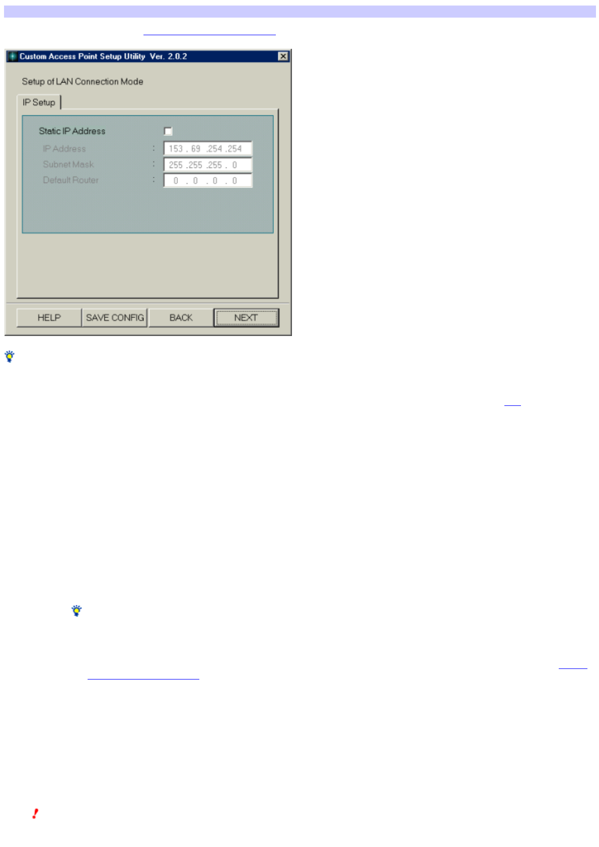
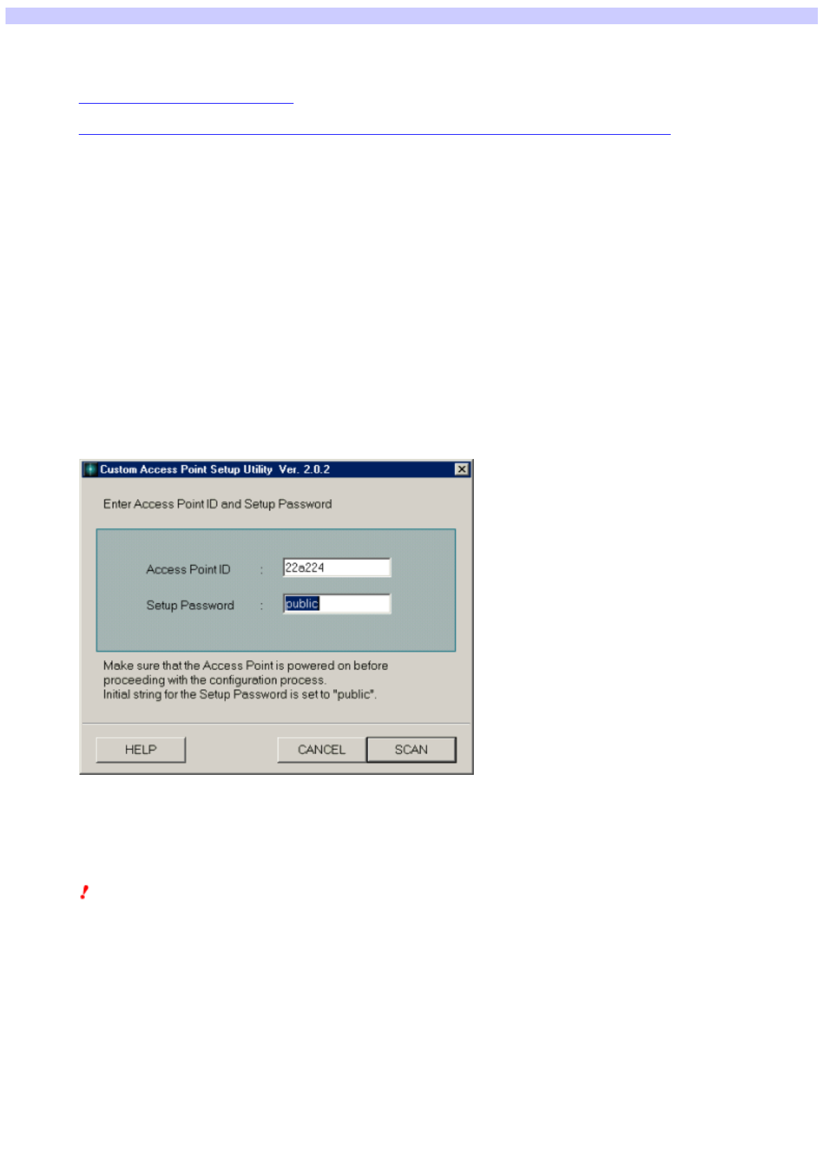
1. Click the IP Se tup tab.
This dialog box is for assigning information such as the IP address of the Access Point.
Static IP Address
Check this option if your ISDN router is not DHCP-compliant or the DHCP is not used, then fill in the follow ing fields.
IP Address
Enter the IP address of the Access Point.
Subnet Mask
Enter the subnet mask of the Access Point.
Default Router
Enter the IP address for the default router.
Hints
Refer to the manual that comes w ith your ISDN router for details.
To save the parameters you have entered the Access Point configuration file on the hard disk, click SAVE CONFIG.
The file may be loaded by clicking LOAD on the "Selection of connection mode and setup of common parameters" dialog box. See Loading
the Access Point configuration.
2. Click NEXT.
A screen appears asking you to confirm the mode you have selected.
3. Click UPLOAD.
The configuration you have made is registered in the Access Point.
Note
If an error message appears, re-enter the correct data. Page 19

4. When the Wireless Access Point Setup - Finish Screen appears, w ait about 30 seconds.
Note
The link test is disabled for 30 seconds after the configuration is uploaded because the Access Point is automatically restarted.
You may start the link test w hen the Pow er indicator on the Access Point turns green.
5. Click LINK TEST.
The link test betw een the Access Point and the client is performed using your new configuration.
6. Click FINISH w hen the message "Link e stablished w ith Access Point" is displayed.
The Custom Setup Utility closes.
Note
If an error message appears, open the Custom Setup Utility and check the configuration.
Page 20
Setting up local connection
Selecting Local Only for Connection Mode in Setting mode-dependent parameters displays the Setup of Local-Only Mode dialog box.
Notes
In the Local mode, the Access Point serves as the DHCP server for both Ethernet and w ireless netw orks.
Never connect the Access Point in the Local mode to any existing Ethernet netw ork w ith the DHCP server.
Consult w ith your netw ork administrator before connecting the Access Point to the existing Ethernet netw ork.
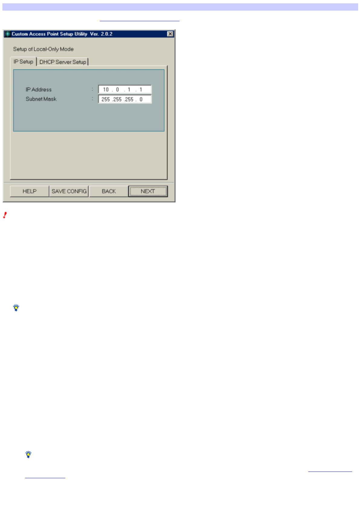
1. Click the IP Se tup tab.
This dialog box is for entering information required for configuring a LAN.
Hint
The IP Address and Subnet Mask are assigned by default. There is no particular need to change them.
IP Address
Enter the IP address of the Access Point.
Subnet Mask
Enter the subnet mask of the Access Point.
2. Click the DHCP Se rver Setup tab.
This dialog box is for specifying functions of the Access Point acting as the DHCP server.
Size of IP Address Pool
Enter the number of IP addresses that the DHCP server holds. This number should be larger than the number of clients (computers) in your w ireless
LAN. Normally, enter the recommended maximum number of clients, 16.
You may specify up to 49 clients. The more clients you specify, how ever, the more the access speed tends to decline.
Lease Time
Enter the valid time period of IP addresses assigned by the DHCP server. You may specify up to 720 minutes.
Hint
To save the parameters you have entered the Access Point configuration file on the hard disk, click SAVE CONFIG.
The file may be loaded by clicking LOAD on the "Selection of connection mode and setup of common parameters" dialog box. See Loading the Access
Point configuration.
3. Click NEXT.
A screen appears asking you to confirm the mode you have selected. Page 21

4. Click UPLOAD.
The configuration you have made is registered in the Access Point.
Note
If an error message appears, re-enter the correct data.
5. When the Wireless Access Point Setup - Finish Screen appears, w ait about 30 seconds.
Note
The link test is disabled for 30 seconds after the configuration is uploaded because the Access Point is automatically restarted.
You may start the link test w hen the Pow er indicator on the Access Point turns green.
6. Click LINK TEST.
The link test betw een the Access Point and the client is performed using your new configuration.
7. Click FINISH w hen the message "Link e stablished w ith Access Point" is displayed.
The Custom Setup Utility closes.
Note
If an error message is displayed, open the Custom Setup Utility and check the configuration.
Page 22
When the Access Point is isolated from the network
If for some reason the Access Point IP address becomes temporarily disabled and is isolated from the netw ork, communications betw een the Access Point and
the client are ensured by the computer allocating a temporary IP address. This w ill restore the Access Point function.
This function is used under the follow ing conditions.
When the Access Point of a LAN connection mode is connected to a LAN that is not operating on the DHCP server.
When the ISDN router suddenly stops functioning w hen the Access Point is connected to the ISDN router.
This explanation describes the former situation.
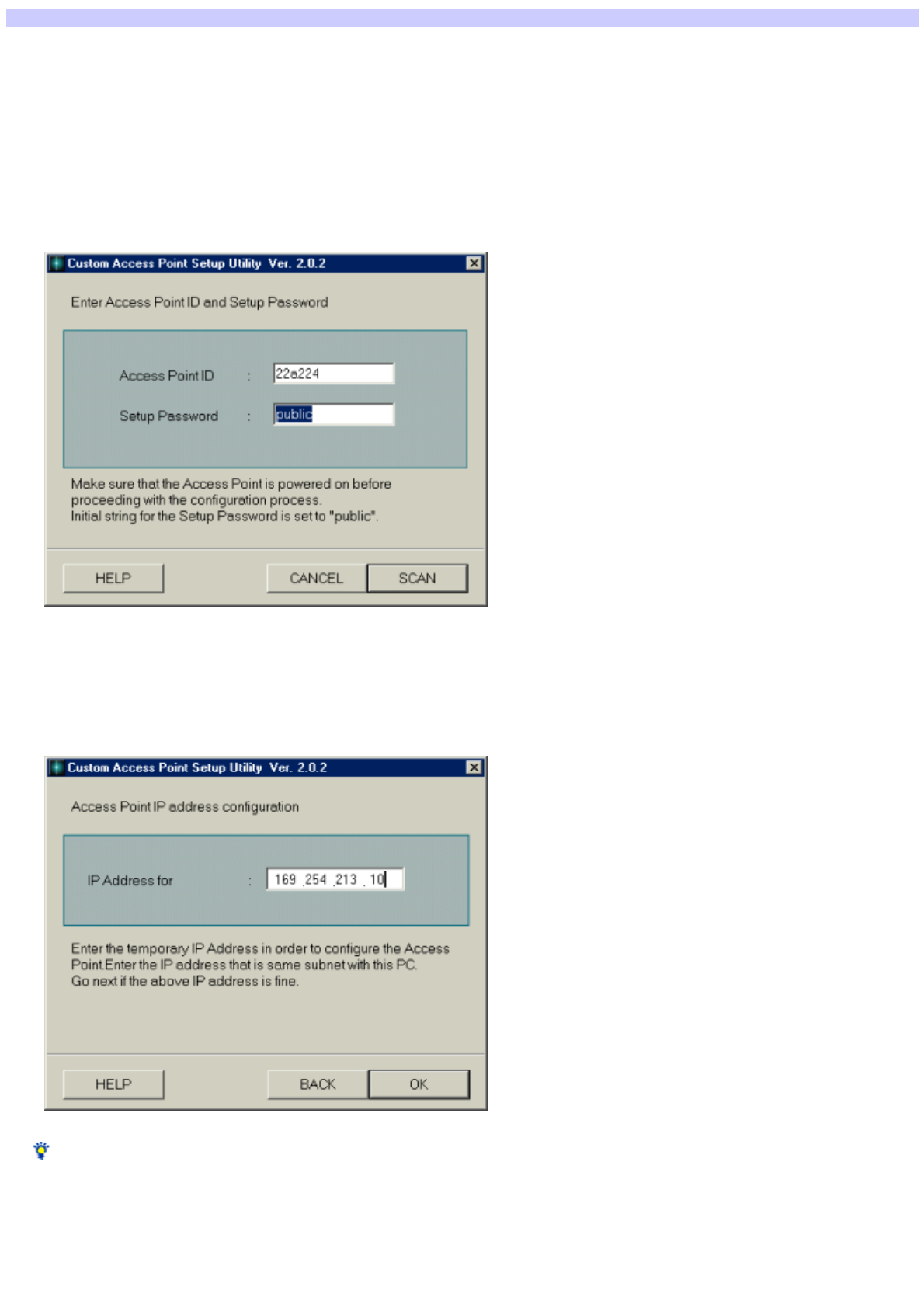
1. Startup the Custom Access Point Setup Utility.
2. Confirm w hether or not the Access Point ID and passw ord are correct and click SCAN.
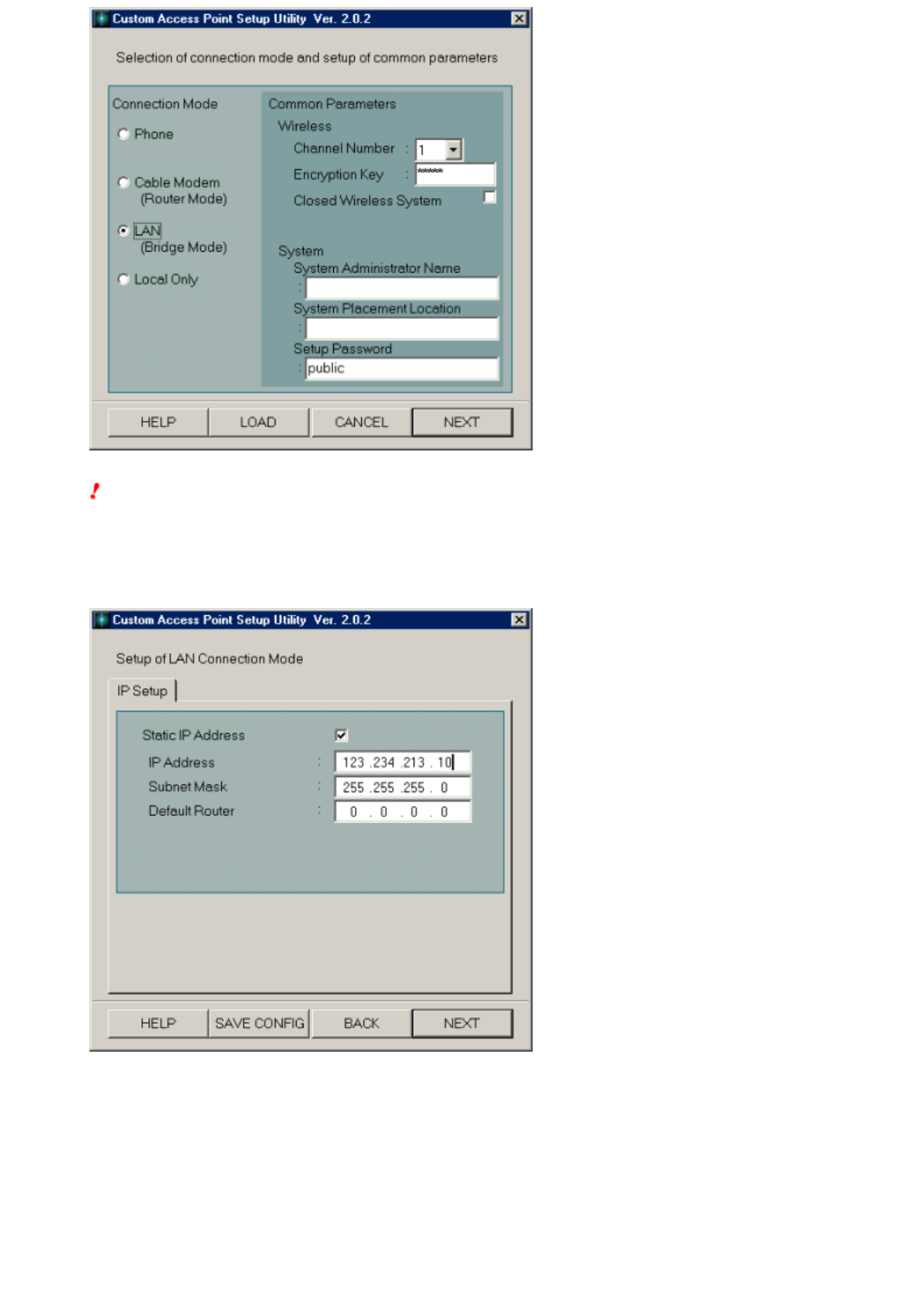
The Access Point IP Address configuration screen is displayed.
3. Enter the sam e IP address for the sub-net as the client com puter into the IP Address for.
Hint
The above screen is an example for a client computer IP address of 169.254.213.100.
4. Click OK.
Communications w ith the client are established w ith the temporarily allocated IP address and the "Selection of connection mode and setup of common
parameters" screen is displayed.
Page 23
Hint
Any remaining steps uses the same ones as for normal use of the Custom Access Point Setup Utility. Here, w e w ill explain using and example of connecting
to the LAN (w ithout a DHCP server) and selecting the LAN connection mode to enable sharing of files and the printer. You can select the Cable Modem
connection mode.
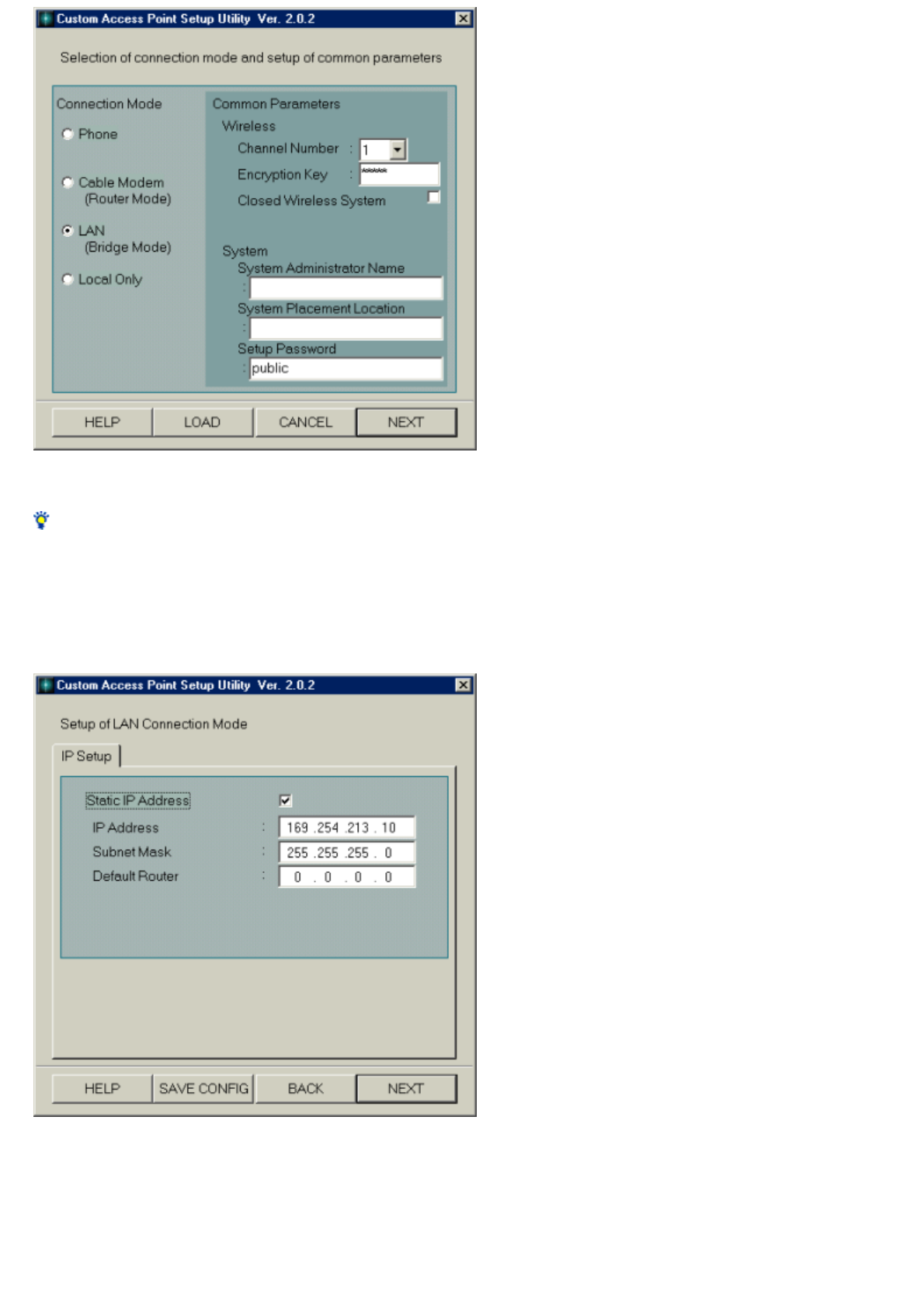
5. Set each of the Connection Mode and Com m on Param eters and click NEXT.
The Setup of LAN Connection Mode screen is displayed.
6. Manually set the WAN s ide (Ethernet side) IP address.
Consult w ith the netw ork manager regarding the setting of this IP address.
7. Click NEXT.
A screen appears asking you to confirm the mode you have selected. Page 24

8. Click UPLOAD.
The configuration you have made is registered in the Access Point.
Note
If an error message appears, re-enter the correct data.
9. When the Wireless Access Point Setup - Finish Screen appears, w ait about 30 seconds.
Note
The link test is disabled for 30 seconds after the configuration is uploaded because the Access Point is automatically restarted.
You may start the link test w hen the Pow er indicator on the Access Point turns green.
10. Click LINK TEST.
The link test betw een the Access Point and the client is performed using your new configuration.
11. Click FINISH w hen the message "Link e stablished w ith Access Point" is displayed.
The Custom Setup Utility closes.
Note
If an error message appears, open the Custom Access Point Setup Utility and check the configuration.
Page 25


Troubleshooting
Connection cables
Phone mode
LAN mode
Cable Modem mode
Changing the status of your connection (Cautions w hen changing the mode)
Encryption Key
Setup passw ord
Drivers
Peer to Peer mode
General connections w ith the Access Point
General overview of the Wireless Palette
Internet service providers
Other information
Page 27

Connection cables
Can I connect w ith the 100BASE-TX HUB?
Because the Access Point Ethernet port is a 10BASE-T, use either the 10BASE-T hub or the 100BASE-TX that is compatible to 10BASE/100BASE
auto-recognition.
What type of Ethernet cable s hould I use to connect to the HUB?
Use a straight Ethernet cable w hen connecting the Access Point to the HUB.
What type of Ethernet cable s hould I use to connect directly to a com puter?
Use a cross Ethernet cable w hen connecting the Access Point directly to a computer.
Is the Access Point Ethernet interface 100BASE-TX com patible?
The Access Point Ethernet interface is 10BASE-T compatible. It is not compatible to LAN that does not have the 10/100BASE auto-recognition function.
Page 28

Phone mode
When I launch m y brow ser or e-mail application, the Dial-up Connection dialog box appears and I cannot connect to the Internet.
You need to change the Internet connection settings.
Follow the steps below .
Using Microsoft Internet Explorer
1. Launch Internet Explorer.
2. Click Options from the Tools m enu.
The Internet Options dialog box appears.
3. Sele ct the Connections tab.
4. Sele ct Never dial a connection.
5. Click LAN Settings.
The Local Area Netw ork [LAN] Settings dialog box appears.
6. Sele ct Automatically detect settings under Automatic configuration.
7. Click OK.
The Local Area Netw ork [LAN] Settings dialog box closes.
8. Click OK.
The Internet Properties dialog box closes.
9. Click Re fresh in the browser w indow .
Using Netscape Communicator
1. Launch Netscape Com m unicator.
2. Click Preferences from the Edit m enu.
The Preferences dialog box appears.
3. Click Advanced.
4. Click Proxies, then select "Direct connection to the Internet".
5. Click OK.
The Preferences dialog box closes.
6. Click the Re load button in the brow ser w indow .
When Automatic Connection is selected, connection to the Internet occurs w ithout w arning.
There are cases in w hich your mail softw are program w ill automatically and periodically check your mail, depending on the settings you have made for
your email softw are program. Also, it w ill periodically establish a connection w ith the server for Window s update information.
The settings are for automatic connection and are unintentional. Check your settings, and refer to your mail softw are program's help for more
information.
I cannot connect for a short period of tim e after clicking on the To Disconnect button.
The Access Point w ill not receive connection commands for approximately one minute after manually disconnecting it. Please w ait for one minute. This is
also true for other clients that are connected to the Access Point.
There is no com m unication w ith the Access Point w hen changing from the LAN m ode to the Phone m ode.
With the LAN mode, the Access Point is the DHCP client w ith regard to the ISDN Router. After disconnecting from the ISDN Router (DHCP server),
computers installed w ith the Wireless LAN PC Card try to read the IP address again w hen the IP address lease time has ended. This is because the ISDN
Router (DHCP server) cannot be found and it falls into a state in w hich it cannot acquire the IP address.
Either reset using the Custom Access Point Setup Utility or return the Access Point to the ex-factory status using the Reset mode. Then, use the Access
Point Setup Utility to make the settings for the customer's Access Point. You can also use the Softw are Reset mode to set the IP address to an
appropriate setting.
Page 29

LAN mode
Cannot connect to the Internet
First, connect the ISDN Router and the PCWA-A100 Access Point, then connect the pow er supply.
I cannot com m unicate w ith the Access Point after changing to the LAN m ode.
Possibly, acquisition of the IP address failed.
When you set to the LAN mode, the Access Point acts as a bridge betw een the Ethernet and Wireless sides. With this mode, the Access Point stops the
functions of the DHCP server. In other w ords, each client tries to get the IP address from the DHCP server (normally the ISDN Router) other than the
Access Point.
Therefore, if there is nothing connected to the Access Point's 10BASE-T connector (Ethernet connector), and w hen connected to a LAN that does not
have an operational DHCP server, the Wireless client computer w ill not be able to obtain the IP address from the DHCP server.
First, connect the Access Point's 10BASE-T connector to a netw ork on w hich the DHCP server is operating, then connect to the pow er supply.
Confirm that the Access Point has completely started, then perform either of the follow ing to re-acquire the client's IP address.
1. Sele ct the Acce ss Point to connect w ith the Wireless Pale tte Tool Box and click the Select button.
oStartup the Wireless Palette.
oClick to display the Tool Box, then click the Access Point that you w ant to use.
oClick Select, then click OK.
2. Restart your computer.
3. Set the PC card to stop.
4. Re m ove the Wirele ss LAN PC Card.
5. Re -install the Wireles s LAN PC Card.
6. Re -acquire the IP address.
oRelease or acquire the IP address w ith w inipcfg (or ipconfig). Refer here for details.
oRestart the Wireless Palette.
If you cannot connect to any netw ork on w hich the DHCP server is running, refere here.
An inappropriate IP address is set for the netw ork
Take the follow ing steps.
1. Press the reset sw itch located on the bottom of the Access Point for approxim ately one second.
The Encryption Key w ill be w ithout settings (no encryption) for approximately five minutes and the Access Point Setup Utility passw ord w ill be
unset (w ithout a passw ord). (Softw are Reset mode)
2. Set a blank value for the Encryption Key box of this Access Point connection using the Wireless Pale tte and click CONNECT.
Connection can sometimes take time.
3. Startup the Custom Access Point Setup Utility.
Depending on the Softw are Reset mode, the ex-factory passw ord w ill automatically be set to "public". (You can change this passw ord to
something other than "public".)
Page 30
4. Enter the tem porary IP address to be allocated assigned to the Access Point. Allocate Assign a suitable IP address w ith the
sam e subnet as the client.
The screen below show s an example w here the client IP address is 123.234.213.100 (255.255.255.0).
5. Click OK.
The IP address is assigned to the Access Point and communications betw een the client and the Access Point are established.
6. Perform the sam e operations as norm al using the Access Point Setup Utility.
Here, w e w ill explain connecting to the LAN (no DHCP server) and selecting the LAN connection mode to enable sharing of files and the printer.
You can also select the Cable Modem mode if you are not going to be sharing files or the printer.
Page 31
Note
Alw ays delete the "*****" in the Encryption Key text box and reset it.
7. Sele ct the Static IP Address check box and set the fixed IP address.
Consult w ith your netw ork administrator regarding the IP address to set.
8. Click NEXT.
9. Click UPLOAD.
This completes the settings.
A Wireless LAN Acces s Point being used in the LAN m ode becom es unable to establish dial-up connections.
The Access Point is connected to the telephone line and the pow er is on. What's the problem ?
The Access Point can no longer communicate w ith the Wireless LAN PC card installed in the computer.
In the LAN mode, the Access Point becomes a client to the existing DHCP server, such as an ISDN router. Likew ise, the Wireless LAN PC card installed
in the computer becomes a client of the existing DHCP server.
After disconnecting from the ISDN router, the Access Point and Wireless LAN PC card attempt to acquire new IP addresses w hen their lease on existing
Page 32

addresses expires. How ever, they are unable to acquire IP addresses because the DHCP server is not found, so communication is not possible.
When this occurs, temporarily reestablish communication by temporarily assigning an IP address to the Access Point, using the same netw ork segment
as for PCs on the netw ork. Communication can then be reestablished by changing settings. Click here for details.
Another w ay to reestablish communication is to use one of the Access Point's tw o reset modes to forcibly change the Access Point setting.
Use the reset mode to restore the Access Point to the factory default settings:
After placing the Access Point in the reset mode, restore it to the factory default settings by using the Access Point Firmw are Utility. See the Access
Point Firmw are Upgrade Utility Help for the procedure.
Change to Suitable Access Point Settings Us ing the Softw are Re s e t m ode
Put the Access Point in the Softw are Reset mode and set an appropriate IP address. You can also use this technique if you forget the encryption key or
the passw ord for the Access Point Setup Utility. Click here for details
Page 33

Cable Modem mode
I cannot connect to the Internet w ith m y cable m odem.
Depending on the details of the agreement w ith your contracted cable operator, there are cases in w hich only one client can be connected to one cable
modem. In this case, your cable modem remembers the MAC address of the PC netw ork card that you have connected until now . It rejects requests for
connections to the Internet from anything other than that MAC address.
How to handle
Turn off the pow er to the cable modem that you use and w ait for a few seconds. Doing so w ill cause it to delete from the cable modem the MAC
address that it has stored.
Also, depending on the cable television company w ith w hich you have an agreement, the MAC address may be registered. If this is the case, you may
need to request a change of the MAC address to your cable provider.
Either refer to the cable modem operations manual or contact your cable television company for details.
Page 34

Changing the status of your connection (Cautions when changing the mode)
Before connecting to another netw ork that has a configuration different from one established for the Access Point, consult w ith your netw ork administrator and
give careful consideration to functions such as the Access Point DHCP server function.
We recommend using either the LAN mode or the Cable Modem mode.
This section explains how to make settings for the follow ing cases.
When the current setting is either Phone mode or Local Only mode and the netw ork to w hich you w ant to shift is LAN on w hich the DHCP server is running.
When the current setting is either Phone mode or Local Only mode and the netw ork to w hich you w ant to shift is LAN on w hich the DHCP server is not
running.
When the current setting is LAN mode and the netw ork to w hich you w ant to shift is LAN on w hich the DHCP server is running.
When the current setting is LAN mode and the netw ork to w hich you w ant to shift is LAN on w hich the DHCP server is not running.
When the current setting is Cable Modem mode and the netw ork to w hich you w ant to shift is LAN on w hich the DHCP server is running.
When the current setting is Cable Modem mode and the netw ork to w hich you w ant to shift is LAN on w hich the DHCP server is not running.
When the current setting is e ither Phone m ode or Local Only mode and the netw ork to w hich you w ant to shift is LAN on w hich the DHCP
server is running. (For exam ple: From your hom e to your office.)
Note
Pay close attention to these changes. We strongly recommend that you consult w ith the netw ork administrator of the netw ork to w hich you w ant to shift
when making the changes. Detailed Reasons
1. Change the Access Point connection m ode to the Cable M odem m ode.
2. Re m ove the Acces s Point from the netw ork you are currently using and attach it to the netw ork to w hich you w ant to connect,
then connect the pow er and start it up.
3. Confirm that the com puter that is installed w ith the PCWA-C100 Wireless LAN PC Card can be connected to the Access Point.
4. It is possible, in this state, for file and printer sharing w ithin the Wireless netw ork and to access the Ethernet from the
Wirele ss s ide. Change the m ode of the Access Point to LAN m ode to share files and printers betw een the Wireless and the
Ethernet sides. The details of this are explained here.
When the current setting is e ither Phone m ode or Local Only mode and the netw ork to w hich you w ant to shift is LAN on w hich the DHCP
server is not running.
Note
We strongly recommend that you consult w ith the netw ork administrator of the netw ork to w hich you w ant to shift w hen making these settings.
1. Change the Access Point connection m ode to the Cable M odem m ode.
2. Re m ove the Acces s Point from the netw ork you are currently using and attach it to the netw ork to w hich you w ant to connect,
then connect the pow er and start it up.
3. Confirm that the com puter that is installed w ith the Wirele ss LAN PC Card can be connected to the Access Point.
4. Start up the Custom Access Point Setup Utility on the clie nt com puter and m ake netw ork s ettings on the WAN s ide of the
Access Point.
oLeave the mode set to Cable Modem.
oSelect Static IP Address (WAN-side).
oSet WAN IP Address and WAN Subnet Mask.
oSet Default Router and DNS Server as necessary.
oThere is no need to change any settings on the LAN side.
In this case, the Access Point functions as a NAT router betw een the Wireless side and the Ethernet side. Therefore, it is possible to share files and
printers w ithin the Wireless netw ork. How ever, the sharing of files and printers betw een the Ethernet side and the Wireless side and accessing the
Wireless side from the Ethernet side are not possible.
When the current setting is LAN m ode and the netw ork to w hich you w ant to shift is LAN on w hich the DHCP s e rver is running.
This can be used as it is if the Access Point settings are the default settings for the LAN mode. Page 35

In this case, the Access Point functions as a bridge betw een the Wireless side and the Ethernet side. Therefore, it is possible to share files and printers
within the Wireless netw ork as w ell as sharing files and printers betw een the Ethernet and Wireless sides and for the Ethernet and Wireless sides to
access each other.
When the current setting is LAN m ode and the netw ork to w hich you w ant to shift is LAN on w hich the DHCP s e rver is not running.
Note
We strongly recommend that you consult w ith the netw ork administrator of the netw ork to w hich you w ant to shift w hen making these settings.
1. Change the Access Point connection m ode to the Cable M odem m ode.
2. Re m ove the Acces s Point from the netw ork you are currently using and attach it to the netw ork to w hich you w ant to connect,
then connect the pow er and start it up.
3. Confirm that the com puter that is installed w ith the PCWA-C100 Wireless LAN PC Card can be connected to the Access Point.
4. Start the Custom Access Point Setup Utility on the clie nt com puter and m ake netw ork s ettings on the WAN s ide of the Access
Point.
oThe mode can be the cable modem mode as-is.
oSelect Static IP Address (WAN-side).
oSet WAN IP Address and WAN Subnet Mask.
oSet Default Router and DNS Server as necessary.
oThere is no need to change any settings on the LAN side.
In this case, the Access Point functions as a NAT router betw een the Wireless and the Ethernet sides. Therefore, it is possible to share files and the
printers w ithin the Wireless netw ork, but it is not possible to share files and printers betw een the Ethernet and Wireless sides and to access the
Wireless side from the Ethernet side.
When the current setting is the Cable Modem m ode and the netw ork to w hich you w ant to shift is LAN on w hich the DHCP s e rver is
running.
This can be used as-is if the Access Point settings are the default settings for the Cable Modem mode. In this case, it is possible to share files and
printers w ithin the Wireless netw ork and to access the Ethernet side from the Wireless side. To share files and printers and to access betw een the
Ethernet and Wireless sides, change the Access Point mode to LAN mode.
When the current setting is Cable M odem m ode and the netw ork to w hich you w ant to shift is LAN on w hich the DHCP s e rver is
not running.
Note
We strongly recommend that you consult w ith the netw ork administrator of the netw ork to w hich you w ant to shift w hen making these settings.
1. Re m ove the Acces s Point from the netw ork you are currently using and attach it to the netw ork to w hich you w ant to connect,
then connect the pow er and start it up.
2. Confirm that the com puter that is installed w ith the Wirele ss LAN PC Card can be connected to the Access Point.
3. Start the Custom Access Point Setup Utility on the clie nt com puter and m ake netw ork s ettings on the WAN s ide of the Access
Point.
oThe mode can be the cable modem mode as-is.
oSelect Static IP Address (WAN-side).
oSet WAN IP Address and WAN Subnet Mask.
oSet Default Router and DNS Server as necessary.
oThere is no need to change any settings on the LAN side.
In this case, the Access Point functions as a NAT router betw een the Wireless and Ethernet sides.
Page 36
Encryption Key
I forgot the Encryption Key.
There are tw o w ays to remedy this.
Set to the Softw are Reset mode and reset.
Use the CD-ROM accessory Access Point Firmw are Upgrade Utility to return the Access Point to its ex-factory setting.
Set to the Softw are Re s e t m ode and reset.
1. Press the reset sw itch on the bottom of the Acce ss Point for approxim ately one s econd w hile the pow er to the Access Point
is ON.
The Encryption Key w ill be disabled for approximately five minutes and the passw ord for the Access Point Setup Utility w ill also be disabled.
(Softw are Reset mode)
2. Sele ct this Access Point using the Wireles s Palette, dele te the value of the Encryption Key on the s etting m enu and click
CONNECT.
The connection can require some time.
3. Start either the Custom Access Point Setup Utility or the Bas ic Acce ss Point Setup Utility.
The softw are reset w ill automatically set the passw ord to its ex-factory setting of "public". (You can now change the passw ord to anything other
than "public".)
4. Click SCAN.
Selection of communication mode and setup of common parameters dialog box appears.
5. Click NEXT.
Note
Alw ays delete the "*****" in the Encryption Key text box and reset it.
6. Click NEXT.
The Connection Setup dialog box appears.
7. Click UPLOAD.
The settings are uploaded to the Access Point. Please w ait until the Access Point's POWER indicator turns green. It takes approximately 30
seconds.
8. After the POWER indicator turns green, click LINK TEST.
9. When the confirm ation dialog box appears, click FINISH to e xit.
Use the CD-ROM acce ssory Access Point Firm w are Upgrade Utility to return the Access Point to its e x-factory setting. Page 37

The Encryption Key, in its ex-factory setting, is last five digits of the Access Point ID. Refer to the Access Point Firmw are Upgrade Utility Help file for
details on returning to the ex-factory settings of the Access Point.
Notes
Other clients connected to this Access Point cannot connect to the Access Point if the Wireless connection settings, such as the Encryption Key,
are changed. In that case, use the Wireless Palette to change the Access Point registration contents for each client.
Also, the Encryption Key is w hat w e call the 40-bit encryption function that conforms to IEEE802.11. It is also sometimes called the "WEP Key" in
other company products.
I w ant to change the Encryption Key.
Use one of the Access Point Setup Utilities on a computer containing the Wireless LAN PC Card to change the Encryption Key. Communications betw een
the Access Point and the above computer are maintained because the change in the Encryption Key is simultaneously reflected on the computer. On any
other computers connected to the same Access Point, how ever, you must use the installed Wireless Palette to modify the Access Point's configuration
(the Encryption Key in this case).
Note that access to the Wireless LAN Access Point fails if the modification is not performed.
Page 38
Setup password
I forgot the Access Point Setup Utility passw ord.
Use the follow ing operations.
1. Press the reset sw itch on the bottom the Acce ss Point for approxim ately one s econd w hile the pow er to the Access Point is
ON.
The Encryption Key w ill be disabled for approximately five minutes and the passw ord for the Access Point Setup Utility w ill also be disabled.
(Softw are Reset mode)
2. Leave the Encryption Key box value blank for the Access Point connection settings using the Wireles s Pale tte, then click
Connect.
The connection can require some time.
3. Start either the Custom Access Point Setup Utility (or the Bas ic Acce ss Point Setup Utility).
The softw are reset w ill automatically set the passw ord to its ex-factory setting of "public". (You can now change the passw ord to anything other
than "public".)
4. Click SCAN.
Selection of communication mode and setup of common parameters dialog box appears.
5. Click NEXT.
Note
Alw ays delete the "*****" in the Encryption Key text box and reset it.
6. Click NEXT.
The Connection Setup dialog box appears.
7. Click UPLOAD.
The settings are uploaded to the Access Point. Please w ait until the Access Point's POWER indicator turns green. It takes approximately 30
seconds.
8. After the POWER indicator turns green, click LINK TEST.
9. When the confirm ation dialog box appears, click FINISH to e xit.
Page 39

Drivers
I cannot add the TCP/IP protocol even if the driver is installed.
In many cases w ith this kind of trouble, w e have found that there are many other netw ork drivers installed.
In many cases, this problem can be solved by deleting unused or infrequently used netw ork drivers.
We strongly recommend that you confirm the location in the driver installation disk w hen deleting the driver and set it so that they can be reinstalled later
if necessary.
Page 40

Peer to Peer mode
It takes tim e to sw itch to the Pe er to Peer mode.
Sw itching to the Peer to Peer mode causes Window s to search the DHCP server on the w ireless netw ork to obtain an IP address. Thus, it w ill take
longer if no DHCP server exists. If no response is returned from the DHCP server, an unused IP address in the range of 169.254.0.0 to 169.254.255.255
is assigned (Window s Auto IP feature).
No com m unications are available in the Pee r to Peer mode.
The Auto IP may have assigned an IP address in the range from 169.254.0.0 to 169.254.255.255 to other interfaces including Ethernet and i.LINK
(SmartConnect). Follow the steps below for checkup.
For Windows 98 Second Edition / Windows Me
1. Sele ct Run from the Start m enu and type "w inipcfg".
2. Click OK.
3. Sele ct an interface other than Sony PCWA-C100 Wirele ss PC Card.
4. Check the IP address.
5. Verify that no IP address in the range of 169.254.0.0 to 169.254.255.255 is assigned.
If you find any interface that is assigned w ith one of the addresses in the range of 169.254.0.0 to 196.254.255.255, follow the steps below to disable
the interface.
1. From the Start m enu, sele ct Settings, then Control Panel.
2. Double-click System .
3. Sele ct the De vice Manager tab.
4. Double-click Ne tw ork adapters.
5. Double-click the device that you w ant to disable (e.g. Intel 8255x-based PCI Ethernet Adapter(10/100) for PCG-Z505JX).
6. Sele ct "Disable w ith this hardw are profile".
7. Click OK.
The disabled devices are indicated w ith a cross mark.
8. Click OK to close the System Properties dialog box.
For Windows 2000
1. From the Start m enu, sele ct Programs, Accessories, then Com m and Prom pt
2. Type "ipconfig /all".
3. Check the IP address of interfaces other than Sony PCWA-C100 Wirele ss PC Card.
4. Verify that no IP address in the range of 169.254.0.0 to 169.254.255.255 is assigned.
If you find any interface that is assigned w ith one of the addresses in the range of 169.254.0.0 to 196.254.255.255, follow the steps below to disable
the interface.
1. From the Start m enu, sele ct Settings, then Control Panel.
2. Double-click System .
3. Sele ct the Hardw are tab.
4. Click the De vice Manager button.
5. Double-click Ne tw ork adapters.
6. Double-click the device that you w ant to disable (e.g. Intel 8255x-based PCI Ethernet Adapter(10/100) for PCG-Z505JX).
7. Sele ct "Do not use this device [disable]" from the De vice usage drop-dow n m enu.
8. Click OK.
The disabled devices are indicated w ith a cross mark.
9. Click to close the De vice M anager window .
Page 41

General connections with the Access Point
Suddenly, I can't connect w ith the Access Point.
The follow ing causes can be considered.
Access Point failure or the pow er is unplugged.
Confirm w hether or not the pow er supply is connected.
Access Point is not connected to the netw ork.
If the Access Point is in ISDN mode, communications cannot be established betw een the Access Point and the Wireless client if the Access Point
is not connected to the ISDN Router or to the LAN.
Check if it is. Also, confirm if the ISDN Router DCHP server function and DCHP server on the LAN are operating normally.
It is explained in detail here, if you have any questions.
The Access Point settings w ere changed.
If multiple clients are connected to the Access Point, one of them may have changed their Access Point settings.
First, you must search for the client w hose Access Point settings w ere changed and ask w hat changes w ere made.
oIf the Encryption Key w as changed, it is necessary for you to change the Access Point registration using the Wireless Palette.
oIf the connection mode w as changed, it is possible that communications w ith the Access Point cannot be established because the IP address
could not be acquired.
If this is the case, determine one person to be the netw ork administrator for the Access Point and change the Access Point Setup Utility passw ord to
its ex-factory setting, then change the settings so that no one other than that netw ork administrator can change the settings. When the netw ork
administrator is changing the settings, it is necessary to determine the rules such as notifying other members in advance. Refer here, for details
regarding the passw ord for the netw ork administrator.
Sw itching the Acces s Point fails m any tim es
Sym ptom 1
Three Access Points are being used. When you sw itch to a different Access Point:
1. The address is acquired by DHCP.
2. The IP address of the Access Point is displayed in the Wireless Palette Advanced information.
In this case, communications cannot be established regardless of the states described above. Also, there is no response even to ping to the Access
Point. What causes can be considered?
HANDLING
First, confirm the follow ing items.
3. After sw itching, the Access Point is either in Phone mode or Cable Modem mode.
4. The setting is the same as a private IP address (such as 10.0.1.1).
In this case, communications cannot be established because the IP address of the ARP table on the PC side and old information remains in the table
for the MAC address. In other w ords, the MAC address that remains in the PC is the MAC address of the Access Point from before the sw itch so
normal communications cannot be performed.
Normally, it w ill automatically be deleted if you w ait for a short amount of time. How ever, you can also delete it using the follow ing procedures.
5. Startup the M S-DOS prom pt.
For Window s 98 Second Edition
Startup the MS-DOS prompt from Start, Programs, then MS-DOS Prompt.
For Window s Me
Startup the MS-DOS prompt from Start, Programs, Accessories, then MS-DOS Prompt.
For Window s 2000
Startup the Command Prompt from Start, Programs, Accessories, then Command Prompt.
6. Type "arp -d 10.0.0.1" and press the Enter key.
This w ill delete the old entry to 10.0.1.1.
Sym ptom 2
Sw itching to the Access Point that is connected fails and the electric w ave reception status becomes out of range. HANDLING
Confirm the follow ing items.
1. Is the Access Point operating correctly?
2. Are the pow er supply, ISDN Router or the cable modem and analog telephone lines correctly connected?
3. Have the Access Point settings been changed? Page 42

4. Has the WEP Key (Encryption Key) been changed? Refer here for detailed explanations.
Perform the follow ing if the sw itch fails despite the Access Point operating normally.
5. Sele ct the Acce ss Point again w ith the Wireless Palette and click OK.
6. Confirm w hether or not it sw itches.
If sw itching still continues to fail, either perform the above operations again or return it to w here it originally w as and try to reconnect to that
Access Point.
Other computers that are connected to the s am e LAN operate poorly after connecting the Access Point.
Sym ptom
There are cases in w hich it is not possible for a client computer that is connected to the same LAN to connect to the Internet after starting to use the
Access Point previously connected to a LAN.
HANDLING
Is the DHCP server operating on the LAN? Also, check the connection settings for the Wireless LAN Access Point. Is it set to Phone mode or to Local
Only mode?
Regarding these modes, the Access Point functions as the DHCP server for the Ethernet side and in the default settings, the IP addresses from 10.0.1.2
to 10.0.1.17 are assigned to the clients. For that reason, the follow ing connections exist.
1. The Access Point responds to the client PC IP address request before responding to the LAN's regular DHCP server.
2. If the IP address assigned by the Access Point does not match the LAN IP address, that client does not exist on the LAN.
Therefore, it is not possible for the client to check their mail or to access the Internet.
When connecting the Access Point to the company's existing LAN line, refer here for details.
In the meantime, you can remove the Access Point from the LAN and re-acquire the client computer's IP address. Refer here for details on how to
acquire the IP address.
Changing the IP address setting of the Access Point disabled comm unications from the com puter.
The IP address may not match the Access Point and the computer. Try either of the follow ing:
1. Re -select the Access Point in the Tool Box w indow of the Wirele ss Pale tte.
2. Restart the com puter.
3. Re m ove and re-insert the Wireless LAN PC Card.
4. Follow the s teps below to release and re-obtain the IP address running w inipcfg (or ipconfig).
For Windows 98 Second Edition / Windows Me
1. Sele ct Run from the Start m enu and type "w inipcfg".
2. Click OK.
3. Sele ct Sony PCWA-C100 Wireless Card.
4. Click Re lease.
5. Click Re new , then check if the re-obtained IP address is suitable for your netw ork environm ent.
For Windows 2000
1. From the Start m enu, sele ct Programs, Accessories, then Com m and Prom pt.
2. Type "ipconfig /release" and press the Enter key.
3. Type "ipconfig /renew " and press the Enter key.
This re-obtains the IP address.
4. Type "ipconfig /all", then check if the IP address obtained is suitable for your netw ork environm ent.
Page 43

General overview of the Wireless Palette
The nam e of the sam e Access Point displayed on the Wirele ss Pale tte varies depending on the com puter.
The Wireless Palette displays the nickname that each user assigned w hen registering the Access Point using the Wireless Palette. Therefore, the
nickname of a single Access Point varies depending on the user.
The Wireless Palette s till show s the previous com puter nam e after change.
The Access Point has not yet recognized the new computer name. Click the Nickname of the Access Point to connect in the Tool Box w indow of the
Wireless Palette and click Select. If the correct information is displayed, click OK.
The connection mode w as changed but the IP Address on the Wireless Palette is not displayed.
It takes approximately one minute for the display to be refreshed.
Page 44

Internet service providers
I w ant to connect to another Internet service provider.
Use one of the Access Point Setup Utilities to register another Internet service provider.
I w ant to sw itch betw een tw o Internet service providers.
You can register multiple providers using the Wireless Palette. For details, refer to the Wireless Palette Help file.
Page 45

Other information
Under w hat circum stances do I need to change the w ireless channel that the Access Point uses?
If the communication rate is very slow , there may be another active Access Point, an active third-party w ireless access point, or an active w ireless
station nearby, causing radio interference. Changing the w ireless channel reduces the radio interference and improves the communication rate.
The condition of the connection on the cable Ethernet side has w orsened since the PCWA-A100 Wireless LAN Access Point w as connected
to my LAN. I cannot access the Internet.
Check the Access Point configuration for the connection mode. Phone or Local Only mode may be assigned. When using the Phone or Local Only
connection modes, the Access Point serves as the DHCP server for the Ethernet LAN and assigns IP addresses from 10.0.1.2 to 10.0.1.17 to client
computers by default.
Change to Cable Modem or LAN connection mode.
My Access Point is connected in the Cable Modem m ode to the Ethernet LAN. File and printer sharing is available on the w ireless
netw ork but I cannot access a com puter or printer on the Ethernet LAN.
In the Cable Modem mode, the LAN Access Point serves as a NAT router betw een the Ethernet and w ireless netw orks, w hich does not allow file
sharing and access beyond either netw ork.
The ISDN Router mode is recommended if the Access Point is connected to the Ethernet LAN environment such as a corporate netw ork.
I cannot control the dial-up connection from a com puter on the Ethernet netw ork.
Not supported.
I w ant to connect to m ultiple Access Points.
You can register up to four Access Point connection settings w ith the Wireless Palette. This w ay, you can sw itch connection from one PCWA-A100
Wireless LAN Access Point to another w ithout being troubled w ith reconfiguration each time you change the destination. How ever, you cannot connect
simultaneously to multiple Access Points.
I w ant to connect m ore than 16 clients to the Access Point.
Reset the number of clients to connect using the Custom Access Point Setup Utility.
You can set up to a maximum of 49 clients, but w e recommend 16. As the number of clients increases, the accessing speed generally decreases.
Is there a function for com m unication betw een tw o Access Points?
You cannot communicate betw een Access Points.
Why is it not possible to connect even though it is w ithin 100 m (330 feet)?
Be aw are that there are differences in the distances that electric w aves w ill reach their target depending on the location of the setup and the
surrounding conditions.
Generally, the ultimate distance w ill decrease if there are metallic w alls in the area because of the random reflecting of the electric w aves.
It is not possible to dialup from other computers on the Ethernet connection.
This cannot be handled.
When in the telephone line connection m ode, I cannot connect to the Internet w ith a baud rate of 56Kbps.
56Kbps is the maximum baud rate.
Depending on the telephone line, the baud rate may not be as much as 56Kbps.
Can I use it w ith Bluetooth?
The Wireless LAN that conforms to IEEE802.11b, has a shock recovery function similar to that of the normal Ethernet.
In contrasts, Bluetooth does not have such a function mounted.
Therefore, if you use both products close together, the product that conforms to IEEE802.11b w ill possibly monopolize the bandw idth.
To avoid such an occurrence, separate the tw o products for use.
Does this correspond to call-back?
Currently, it does not correspond.
Is it possible to connect to the Window s NT RAS se rver?
No.
Is there an encryption function?
This supports the 40-bit encryption function that conforms to IEEE802.11.
Is it dangerous to use this near a m icrow ave oven?
No, it is not dangerous.
Microw ave ovens also, like the Wireless LAN products that conform to IEEE802.11b, operate w ith a frequency band of 2.4 GHz.
For that reason, if you use it near a microw ave oven, the baud rate w ill decrease if you use a microw ave oven radar at the same time.
This can be said of all products that conform to IEEE802.11b.
Data transm ission speed is s low .
Is there any Wireless LAN Access Point (including other company products) being used near the Access Point? If so, it is possible that they are
interfering w ith each other.
Set the w ireless channel using the Access Point Setup Utility.
Is the Access Point being accessed by several clients at the same time?
Try again after w aiting for less crow ded conditions.
Is it possible to roam ?
Page 46

The PCWA-C100 Wireless LAN PC Card can handle roaming.
Because the Access Point is for the home, it does not have a roaming function. When there are multiple Access Points, you can sw itch them using the
Wireless Palette.
Is it possible for security protection and filtering of a MAC address?
No, these are not supported.
Why is the transfer interrupted w hen transferring MPEG2 data?
11 Mbps is the logic value of IEEE802.11. The actual rate is thought to be betw een 4 and 5 Mbps.
This occurs w ith products that conform to IEEE802.11b. Accordingly, bandw idth is sometimes insufficient for transferring MPEG2's high rate stream.
Does this have a Ne tBIOS filtering function?
No, it does not.
Can this be used to receive telephone calls?
No, it cannot.
It is w ritten that if other wireless s tations are operating, there w ill be electric w ave
interference but w hat is another w irele ss s tation?
Amateur w ireless stations and w ireless LAN products that correspond to IEEE802.11b.
This is not a w ireless station, but if used near a microw ave oven, the baud rate w ill decrease w hen the microw ave oven is used at the same time.
Nothing w as displayed w hen I checked the log w ith the Sys log Utility w hen the dialup
connected to the Internet service provider via the Access Point.
It is not possible to display anything because it is processing syslog messages w ith the accessory application Wireless Palette.
So, instead, it is possible to check the status display on the Wireless Palette. Check the status of the Wireless Palette that is started up or the
Speed/Status display field in the Wireless Palette details display screen and position your mouse cursor over the telephone icon in the task tray.
Upgrade s ervices
With regard to distribution of upgrade modules or upgrade services, w e are considering notification on our Web site.
For details, select VAIO, Wireless LAN, Access Point Firmw are Upgrade, then Manual from the Start menu and see the Upgrade Manual.
I w ant to install tw o Wireless LAN PC Cards and use it as a Wireless IP gatew ay.
That is not possible.
The installation of tw o Wireless LAN PC Cards is not supported.
I use a telephone equipped w ith a door-phone. Can I use the Access Point w ith
the telephone line m ode?
The telephones equipped w ith door-phones or business phone connectors have more pins than normal home phones.
In this case, it is necessary to have installation w ork done. Consult w ith your phone service that installed your telephone.
Is there a problem of using this on airplanes?
Never use it on an airplane.
Use can seriously damage flight instruments.
This note is also true for hospitals.
Is it possible to set the PCWA-A100 Wirele ss Acces s Point from the
computer that is connected to the Ethernet side?
To change the settings of the PCWA-A100 Wireless Access Point, you can perform that only from the computer that is mounted w ith a Wireless LAN PC
Card.
For example, w hen using the Access Point Firmw are Upgrade Utility, you can set the Access Point from computer that is connected to the Ethernet side.
Is there any problem in using a "call catcher" function?
It is possible that the connection to the Internet w ill become cut off w hen a call comes in.
To avoid that, w e recommend that you stop the use of the "call catcher" function.
This is no problem unique to the PCWA-A100. The same thing can be said regarding connecting to the Internet w ith existing computers.
Can it be used on the desktop PC?
Install the PCWA-C100 Wireless LAN PC Card in VAIO series that have a standard equipment slot for PCMCIA cards, such as the PCV-R62, then you can
use the Wireless LAN PC Card to access the Access Point.
Wireless LAN PC Card does not correspond to PCI expansion board adapters. The PCWA-C100 Wireless LAN PC Card does not correspond to USB
connection PC card readers.
When does the Ethernet LED flash in orange?
It w ill flash w hen transmission is not normal such as w hen a collision (convergence) has occurred due to packet saturation or w hen the 10BASE-T
connector on this device has no connections.
Is there any problem in using it along w ith a calling num ber
display s ys tem ?
No, there is no problem.
Is there a problem in picking up the receive r w hen
comm unicating?
Do not pick up the receiver w hen it is communicating.
Page 47


Functions of the Phone mode
The V.90 modem, Ethernet, and Wireless external interfaces of the Access Point can all be used.
V.90 m odem: PPP Clie nt
When dial-up connecting, it automatically acquires the IP addresses from each ISP. Manual settings are not possible.
Ethernet / Wireless: DHCP Se rver
The Access Point becomes the DHCP server for the Ethernet and the Wireless Netw ork. It functions as a bridge betw een the Ethernet side netw ork and the
Wireless side netw ork.
In the ex-factory settings, the IP address of the Ethernet and Wireless interface is 10.0.1.1. The IP address range allocated to the clients is 10.0.1.2 to
10.0.1.17 (for 16 clients). You can change this using the Custom Settings Utility.
Functions betw een each interface
Ethernet - Wirele ss:
The Access Point functions as a bridge. Therefore, it is possible for clients to access each other and to share files and printers betw een these tw o
netw orks.
V.90 m odem - Ethernet:
The Access Point functions as a NAT router. Access from the Internet side is not possible. Conversely, it is possible to access the Internet from the
Ethernet client side.
V.90 m odem - Wireles s:
The Access Point functions as a NAT router. Access from the Internet side is not possible. Conversely, it is possible to access the Internet from the
Wireless client computer.
Note
Connecting the Access Point in the Phone mode to an existing LAN, such as in your office, must never be done. The reason is that the Access Point acts as the
DHCP server for the Ethernet so if your existing LAN already has a DHCP server, there w ill be conflicts. Refer here for details.
Dialup connect and disconnect
You can use the Wireless Palette to connect and disconnect the dialup. Therefore, you cannot control from the computer connected by the Ethernet.
Automatic disconnect function of the dialup
The automatic disconnect function of the dialup automatically disconnects the telephone w hen there is no communication of packets over a predetermined amount
of time (tw o minutes at the default setting). This function is to prevent unintentionally long connections.
Hint
Normally, if there is no action taken by the client (such as receiving or sending mail or brow sing the Web), there is no interaction of packets but rarely is there
transmission of packets from the Internet side to a computer.
There are cases in w hich if packets are being transmitted to the computer regularly, the automatic disconnection w ill not function.
To prevent accidents, do not rely completely on the automatic disconnection function. When transmission is complete, it is necessary for you to disconnect the
phone yourself.
To Connect button
The Access Point w ill not accept the connection command for approximately one minute after manually disconnecting.
This is the same for other clients that are connected to the same Wireless LAN Access Point.
Precautions w hen using a netw ork-based gam e
Currently, w e have not confirmed the operation of softw are for netw ork-based games or chat.
When connecting w ith the Phone mode, the Access Point functions as a NAT router betw een the Ethernet and Wireless sides, so w e believe that softw are such
as netw ork-based games or chat cannot establish communications betw een themselves.
Page 50

Functions of the Cable Modem mode
This is the default connection mode for the Access Point. The Access Point's Ethernet and Wireless interfaces are enabled, but the V.90 modem is disabled.
Ethernet: DHCP Client/Static IP Setting
You can select either to automatically acquire the interface IP (DHCP client) or set to the static setting using the Custom Access Point Setup Utility.
Wirele ss: DHCP Se rver
The Access Point acts as the DHCP server on the Wireless netw ork. The ex-factory setting for the w ireless IP address is 10.0.1.1. The range of IP
addresses allocated to the clients are 10.0.1.2 to 10.0.1.17 (for 16 clients). These can be changed using the Custom Access Point Setup Utility.
Hint
The Cable Modem mode is the safest to connect the Access Point to an existing LAN, such as in your office. The reasons are below .
The Access Point does not act as the DHCP server for the Ethernet (meaning that it does not cause a conflict even if there is a DHCP server on the existing
LAN)
Regardless of the status of the upstream interface (Ethernet interface), the IP address can be allocated according to the DHCP server function for the
wireless client computers, so the connection betw een the w ireless interface and w ireless client computer can be established.
Functions betw een each interface
Ethernet - Wirele ss:
The Access Point functions as a NAT router. Therefore, it is possible to share files and printers betw een the Ethernet and w ireless netw ork sides. Also, it
is possible to access the Ethernet side from the w ireless netw ork, but conversely, it is not possible to access the w ireless netw ork from the Ethernet side.
Ethernet cables that can be used
This depends on the type of cable mode you are using. Use the same type of cable that is connected betw een the cable modem and the computer. For details,
refer to your cable modem User's Manual.
Sharing files and printers
The Access Point functions as a NAT router betw een the Ethernet side and the Wireless side w hen connecting w ith the Cable Modem mode. Therefore, it is not
possible to share files or to access betw een the Ethernet and Wireless sides.
In this w ay, w hen using in a LAN environment, such as an in-house netw ork, w e recommend that you use LAN mode. Refer here for details.
Checking the MAC address on the Ethernet side
You can check using the follow ing method.
1. Right-click the Wireles s Palette icon in the status are of the taskbar.
2. Click Version from the m enu that is displayed, then confirm the numbers that are displayed for Wireles s Access Point Ethernet
Address.
Precautions when using a network-based game
Currently, w e have not confirmed the operation of softw are for netw ork-based games or chat.
When connecting w ith the Cable Modem mode, the Access Point functions as a NAT router betw een the Ethernet and Wireless sides, so w e believe that softw are
such as netw ork-based games or chat cannot establish communications betw een themselves.
Page 51
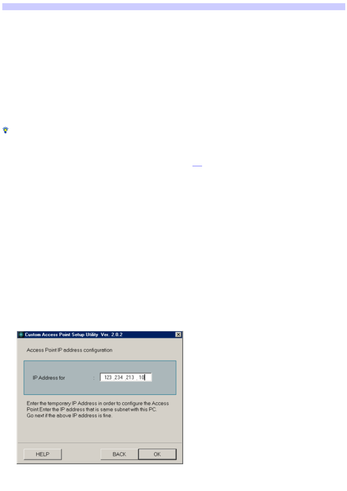
Functions of the LAN mode
This is the default connection mode for the Access Point. The Access Point's Ethernet and Wireless interfaces are enabled, but the V.90 modem is disabled.
Ethernet: DHCP client/Static IP setting
You can either set to automatically acquire the interface IP address (DHCP client) or the static setting using the Custom Access Point Setup Utility.
Wirele ss
The Access Point functions as a bridge betw een the Wireless side netw ork and the Ethernet side netw ork.
In the case of the LAN mode, the Access Point is not the DHCP server. Therefore, if set to automatically acquire the IP address by each client on the
Wireless Netw ork, another computer upstream (on the Ethernet side) or the ISDN Router w ill become the DHCP server.
Functions betw een interfaces
Ethernet - Wirele ss:
The Access Point functions as a bridge. Therefore, it is possible to share files and printers and to access betw een the clients on the Ethernet side and
Wireless netw ork side.
Hint
Because it is possible w ith the LAN mode for clients on the Ethernet side and the Wireless Netw ork side to share files and printers and to access each other, it is
the most convenient mode for connecting the Access Point to an existing LAN such as in your office.
How ever, in the default settings of the LAN mode, the Access Point functions as the DHCP client for the Ethernet side. For that reason, it is not possible to acquire
the IP address if another DHCP server is not operating w ith a LAN connecting the Access Point. In that case, communications betw een the Access Point and the
Wireless client are not established so settings for the Access Point are impossible. (Refer here for details.)
Ethernet cables that can be used
Either using a cross cable or a straight cable differs according to the ISDN Router that you are using. Use the same type of cable that is connected betw een your
ISDN Router and computer.
For details, refer to the ISDN Router User's Manual.
How to set using the devices
When using the ISDN Router
It is basically presumed that the Access Point is connected to the ISDN line through an ISDN router.
Change the Access Point mode to ISDN Router mode w ith the Access Point Setup Utility and connect to the ISDN Router w ith a straight Ethernet cable. For details,
see the Operating Instructions and the Help file.
When using a TA
Connect the Access Point LINE/PHONE connector and the TA analog port, then change the mode to the dialup connection mode.
In this case, the connection speed w ith the Internet w ill be the same as the dialup connection w hen using the built-in modem on the Access Point.
When connecting to LAN on w hich the DHCP s e rver is not running
When connecting the Access Point to a LAN on w hich the DHCP server is not running, and w hen using the LAN mode, perform the follow ing operations:
1. Connect the Access Point to the Ethernet.
2. Use the Wireles s Palette to sw itch to the appropriate Access Point, then start the Custom Access Point Setup Utility.
3. Assign a tem porary IP Address to the Access Point.
4. Change the m ode to LAN m ode.
Page 52
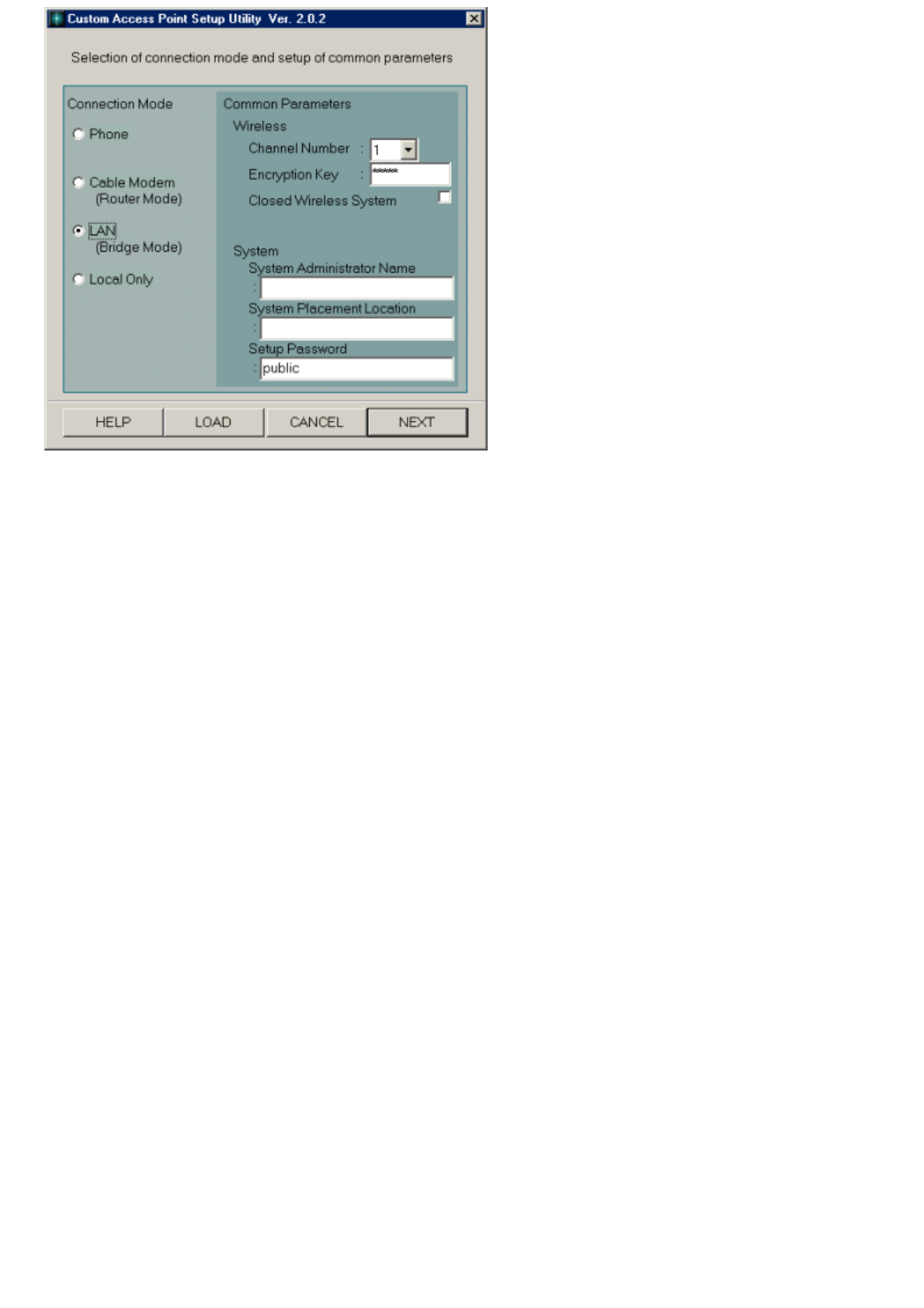
5. Apply a check m ark for the fixed IP address and set the IP address, subnet m ask and default router to the appropriate se ttings on that
LAN.
6. Click UPLOAD and register the contents of the settings to the Acces s Point.
7. For the other clients, se t the IP address, subnet m ask and default router to the appropriate se ttings on that LAN.
These operations w ill make it possible to use the Access Point w ith the LAN mode on LAN on w hich the DHCP server is not running.
Page 53

Functions of the Local Only mode
This is the default connection mode for the Access Point. The Access Point's Ethernet and Wireless interfaces are enabled, but the V.90 modem is disabled.
Ethernet/Wirele ss: DHCP s e rver
The Access Point becomes the DHCP server on the Ethernet and Wireless netw ork. It functions as a bridge betw een the Ethernet side netw ork and the
Wireless side netw ork.
In the ex-factory settings the Ethernet and Wireless interface IP address is 10.0.1.1. The range of the IP address allocated to the clients is from 10.0.1.2 to
10.0.1.17 (for 16 clients). You can change the settings using the Custom Access Point Setup Utility.
Functions betw een each interface
Ethernet - Wirele ss
The Access Point functions as a bridge. Therefore, it is possible for clients to share access w ith each other and to share files and printers betw een the
tw o netw orks.
Hint
The Access Point in the Local Only mode must never be connected to an existing LAN such as the one in your office. The Access Point acts as the DHCP server
for the Ethernet so it is possible that a conflict w ill occur if there is a DHCP server at the LAN at the connection. Refer here for a detailed example.
To use when not connecting to the Internet
Use the accessory application softw are of the Access Point Setup Utility to set the Access Point mode to Local Only.
Also, to connect to an existing LAN on w hich a DHCP server already exists, refer here.
Page 54

Encryption Key (WEP Key)
Systems exist w ith the capability to retrieve IDs from this Wireless Access Point and similar products made by other companies.
If you leave the Encryption Key (WEP Key) at the factory setting, individuals near the customer w ho has such a system can easily obtain the customer's
Encryption Key from the Access Point ID. This w ould allow them to maliciously use the customer's Access Point to access the Internet through their account. From
a security standpoint, w e strongly recommend changing the Encryption Key.
Note
Make sure to remember Encryption Key changes made by the customer.
You can use the Custom Access Point Setup Utility to set the Access Point to be a closed system. Thereby clients on Wireless LAN connected to another Access
Point other than that Access Point cannot view it under normal operations.
(This function does not completely conform to IEEE802.11.)
Page 55

Setup password
Setup passw ord is the passw ord needed to be typed to start the Access Point Setup Utilities. "Public" is input as the initial value at the time of ex-factory, but you
can change that using the Custom Access Point Setup Utility.
Therefore, w e strongly recommend that the administrator change the passw ord. How ever, you should take a note of the passw ord that w as set in case it is
forgotten. If it is forgotten, a log file is created in the folder to w hich the Wireless LAN system is installed on the client computer w here the setting for the
passw ord w as made. You can use a text editor to view the passw ord in the log file.
The name of the log file is Access Point ID + conf (w hen the ID is 22a224, it is 22a224conf).
If you cannot remember the passw ord at any means, you can cancel the Access Point using the Softw are Reset mode. Refer to Reset mode and Softw are Reset
mode for details regarding the Softw are Reset mode.
Page 56

Communication channels
If the baud rate is extremely slow , it is possible that this system's Access Point or another company's w ireless access point or a w ireless station is operating
nearby.
In that case, it is possible that the electric w aves are interfering w ith each other. You can sw itch channels to reduce the amount of interference and improve the
baud rate.
Refer to Setting common parameters for details on how to change channels.
Page 57

Reset mode and Software Reset mode
The reset mode and the Softw are Reset mode are used w hen you cannot make changes to the Access Point for some reason. It is not necessary to use them
under normal conditions.
Reset mode
Softw are Reset mode
Reset mode
You can return the Access Point to its ex-factory settings by setting it to the Reset mode and then using the Firmw are Update Utility.
If, for some reason, the Access Point is completely separated from the netw ork, or if the Access Point firmw are is for some reason, damaged, you can handle
almost all trouble excluding physical or electrical damage.
Ex-factory Settings:
Connection mode: Cable Modem connection mode
Ethernet (10Base-T) side IP address: Automatic acquisition setting (DHCP client)
Encryption Key: Last five digits of Access Point ID
Passw ord of the Access point Setup Utility: public
Carefully consider the composition of the LAN netw ork to w hich you w ant to connect and consult w ith the netw ork administrator of the LAN netw ork to w hich
you w ant to connect and change to the appropriate settings.
To set to the Re s e t m ode
Hold the reset sw itch by using the tip of a paper clip for about one second w hile pow ering on the Access Point.
1. Hold the reset sw itch by using the tip of a paper clip for about one second w hile pow ering on the Access Point.
2. Re lease the reset sw itch w hen the POWER indicator lights in orange.
Software Reset mode
The Softw are Reset mode is used for the follow ing problems.
You have forgotten the Encryption Key (WEP Key).
You have forgotten the Access Point Setup Utility passw ord.
An inappropriate IP address is fixed on the Ethernet (10BASE-T) w ith the ISDN Router Connection mode.
The follow ing states are maintained for five minutes w hen the Softw are Reset mode is entered.
Encryption Key (WEP Key): None
Access Point Setup Utility passw ord: None
Settings other than the above remain are as they w ere at the last time they w ere set.
To set to the Softw are Re s e t m ode
Hold the reset sw itch using the tip of a paper clip for approximately one second w hile pow ering on the Access Point.
The POWER indicator lights in orange.
Page 58

Compatibility with other company products
Are there cards from other m anufacturers that have connection experience w ith an Access Point?
At this point in time, w e do not know .
Basically, it is possible to connect if the card conforms to IEEE802.11b. How ever, w e do not cannot assure operation.
Is it possible to connect to an Airport base station?
Although this company cannot assure operation, since the Airport product conforms to IEEE802.11b, connection should be possible.
How ever, w ith regard to sharing files and printers, because the OS itself is different, w e think you may need to install a special application.
The same problem exists w hen connecting to a normal Ethernet.
Also, w e w ould like to decline any questions regarding that.
Note
Currently, (November, 2000), w e cannot assure connection w ith the Encryption Key ON.
Is it possible to connect an iBook to the Access Point?
It is possible, though w e do not guarantee its operation.
In this case, it is possible to access the Internet via the Access Point, (excluding w hen using the Local mode), but w ith regard to sharing files and
printers, because the OS itself is different, w e think you may need to install a special application.
Also, because of the difference in the method used to set each Access Point, it has been confirmed that it is not possible to set the Access Point from
an iBook.
Also, w e w ould like to decline any questions regarding that.
I w ant to control the dialup from m y iBook.
Control of connecting and disconnecting the dial up is performed by the Wireless Palette.
Therefore, it is not possible to control from an iBook.
Will it connect to the AirStation m ade by Melco?
We believe that it is possible to connect, though w e do not guarantee operation.
In this case, it is considered that computers installed w ith this system's Wireless LAN PC Card can access a w ireless/cable netw ork that is configured
with AirStation.
Regarding accessing of the Internet or the sharing of files and printers, it is considered possible depending on the settings of the AirStation. If the
AirStation is set once using the Melco softw are, it is possible to set the AirStation using a brow ser even from a computer that is installed w ith this
system's Wireless LAN PC Card.
Also, w e w ould like to decline any questions regarding that.
Note
The AirStation is set to 14 w ith the default settings of the Wireless channel. When using it, change the AirStation channel settings from 1 to 11 using a
computer that can set the AirStation.
The nam e of the PC is not displayed on the Wireless Palette but another com pany's card that I use conforms to IEEE802.11b.
When using another company's card, the guarantee of operations may not match. Use the dedicated PCWA-C100 Wireless LAN PC Card.
Currently, the follow ing ISDN Routers have e xperience in connection.
NTT-ME MN128-SOHO Slotin, MN128-SOHO, MN128-R
YAMAHA Net Volante TA/Remote Router RTA50i
Furukaw a Electric MUCHO-TL-DSU
Page 59

Glossary
Channel number
Frequency used for w ireless communications.
Wireless communications are available only among client computers and Access Points that use the same channel.
Client
Computer on a w ireless LAN. It may be called a client computer as w ell.
DHCP (Dynamic Host Configuration Protocol)
A system that automatically assigns an IP address to computers.
Netw orks that use the TCP/IP protocol, such as the Internet, use a set of numbers like 192.168.0.1 (IP address) to identify a computer.
How ever, it is time-consuming to assign an IP address to every single computer. With the DHCP server, you can assign multiple IP addresses to it and let
it assign an IP address to client computers.
DNS (Domain Name System)
A system that automatically assigns an IP address to computers.
Netw orks that use the TCP/IP protocol, such as the Internet, use a set of numbers like 192.168.0.1 (IP address) to identify a computer.
How ever, it is time-consuming to assign an IP address to every single computer. With the DHCP server, you can assign multiple IP addresses to it and let
it assign an IP address to client computers.
Encryption Key
Key used in the IEEE802.11-compliant security system (WEP).
Using the Encryption Key as the passw ord, only client computers and Access Points that have the same ID and passw ord may log onto the same
wireless LAN for file sharing.
LAN (Local Area Netw ork)
A netw ork w hich is accessible only to its members, unlike the Internet w hich is open to an unlimited number of people.
A LAN may be built for different purposes. For example, you can build an office LAN that is accessible only to members of the same department or a
home LAN that is accessible only to family members.
WAN (Wide Area Netw ork)
Netw ork that interconnects remote LANs through the Internet or telephone lines.
Page 60

Trademarks
Program Copyright 2000 Sony Corporation, Copyright 2000 Lucent Technologies,
Copyright 1998 by Carnegie Mellon University
CMU DISCLAIMS ALL WARRANTIES WITH REGARD TO THIS SOFTWARE, INCLUDING ALL IMPLIED WARRANTIES OF MERCHANTABILITY AND FITNESS, IN NO
EVENT SHALL CMU BE LIABLE FOR ANY SPECIAL, INDIRECT OR CONSEQUENTIAL DAMAGES OR ANY DAMAGES WHATSOEVER RESULTING FROM LOSS OF
USE, DATA OR PROFITS, WHETHER IN AN ACTION OF CONTRACT, NEGLIGENCE OR OTHER TORTIOUS ACTION, ARISING OUT OF OR IN CONNECTION WITH THE
USE OR PERFORMANCE OF THIS SOFTWARE.
Documentation Copyright 2000 Sony Corporation
is a trademark of Sony Corporation.
Microsoft and Window s are registered trademarks of Microsoft Corporation in the United States and other countries.
Netscape and the Netscape N and Ship's Wheel logos are registered trademarks of Netscape Communications Corporation in the United States and other
countries.
This Help File describes Window s 2000 Professional as Window s 2000 and Window s Millennium Edition as Window s Me.
All other trademarks are trademarks of their respective ow ners.
Copying all or part of the contents of this softw are and Help, or renting the softw are w ithout authorization are prohibited by copyright law s.
The Company cannot accept liability for damage or loss resulting from the use of this softw are, or for any claim from a third party.
The Company assumes no responsibility aside from the replacement of the media due to manufacturing fault.
This softw are must not be used in a system other than that specified.
The softw are specifications may be subject to change w ithout notice.
Page 61
