Sony STR DH700 User Manual Operating Instructions STRDH700 US
User manual STRDH700_US Sony STR-DH700 Hifi Receiver User Manuals and Instruction Guides
User Manual: Sony STR-DH700 Operating Instructions
Open the PDF directly: View PDF ![]() .
.
Page Count: 108 [warning: Documents this large are best viewed by clicking the View PDF Link!]
- Description and location of parts
- Getting Started
- 1: Installing the speakers
- 2: Connecting the speakers
- 3: Connecting the TV
- 4a: Connecting the audio components
- 4b: Connecting the video components
- 5: Connecting the antennas (aerials)
- 6: Preparing the receiver and the remote
- 7: Selecting the speaker system
- 8: Calibrating the appropriate settings automatically (AUTO CALIBRATION)
- 9: Adjusting the speaker levels and balance (TEST TONE)
- Playback
- Amplifier Operations
- Navigating through menus
- Adjusting the level (LEVEL menu)
- Adjusting the equalizer (EQ menu)
- Settings for the surround sound (SUR menu)
- Settings for the tuner (TUNER menu)
- Settings for the audio (AUDIO menu)
- Settings for the HDMI (HDMI menu)
- Settings for the system (SYSTEM menu)
- Calibrating the appropriate settings automatically (A. CAL menu)
- Settings for the S-AIR (S. AIR menu)
- Enjoying Surround Sound
- Tuner Operations
- Listening to FM/AM radio
- Presetting FM/AM radio stations
- Listening to Satellite Radio
- Connecting the SIRIUS Satellite Radio
- Preparing to listen to the SIRIUS Satellite Radio
- Selecting a channel of the SIRIUS Satellite Radio
- Presetting SIRIUS Satellite Radio channels
- Restricting access to specific channels (Parental Lock) (SIRIUS only)
- “BRAVIA” Sync Features
- S-AIR Operations
- Other Operations
- Using the Remote
- Additional Information

©2009 Sony Corporation
4-129-783-11(3)
Multi Channel AV
Receiver
Operating Instructions
STR-DH700
2US
To reduce the risk of fire or electric
shock, do not expose this apparatus to
rain or moisture.
To reduce the risk of fire, do not cover the
ventilation opening of the apparatus with
newspapers, tablecloths, curtains, etc. Do not place
the naked flame sources such as lighted candles on
the apparatus.
Do not install the appliance in a confined space, such
as a bookcase or built-in cabinet.
To reduce the risk of fire or electric shock, do not
expose this apparatus to dripping or splashing, and
do not place objects filled with liquids, such as
vases, on the apparatus.
As the main plug is used to disconnect the unit from
the mains, connect the unit to an easily accessible
AC outlet. Should you notice an abnormality in the
unit, disconnect the main plug from the AC outlet
immediately.
Do not expose batteries or apparatus with battery-
installed to excessive heat such as sunshine, fire or
the like.
The unit is not disconnected from the mains as long
as it is connected to the AC outlet, even if the unit
itself has been turned off.
Excessive sound pressure from earphones and
headphones can cause hearing loss.
For customers in the United
States and Canada
This symbol is intended to alert
the user to the presence of the Hot
Surface that may be hot if it is
touched during the normal
operation.
ENERGY STAR® is a U.S. registered
mark.
As an ENERGY STAR® partner, Sony
Corporation has determined that this
product meets the ENERGY STAR®
guidelines for energy efficiency.
For customers in the United
States
Owner’s Record
The model and serial numbers are located on the rear
of the unit. Record these numbers in the space
provided below. Refer to them whenever you call
upon your Sony dealer regarding this product.
Model No. Serial No.
This symbol is intended to alert the
user to the presence of uninsulated
“dangerous voltage” within the
product’s enclosure that may be of
sufficient magnitude to constitute a
risk of electric shock to persons.
This symbol is intended to alert the
user to the presence of important
operating and maintenance
(servicing) instructions in the
literature accompanying the
appliance.
Important Safety Instructions
1) Read these instructions.
2) Keep these instructions.
3) Heed all warnings.
4) Follow all instructions.
5) Do not use this apparatus near water.
6) Clean only with dry cloth.
7) Do not block any ventilation openings. Install in
accordance with the manufacturer’s instructions.
8) Do not install near any heat sources such as
radiators, heat registers, stoves, or other
apparatus (including amplifiers) that produce
heat.
9) Do not defeat the safety purpose of the polarized
or grounding-type plug. A polarized plug has
two blades with one wider than the other. A
grounding type plug has two blades and a third
grounding prong. The wide blade or the third
prong are provided for your safety. If the
provided plug does not fit into your outlet,
consult an electrician for replacement of the
obsolete outlet.
10)Protect the power cord from being walked on or
pinched particularly at plugs, convenience
receptacles, and the point where they exit from
the apparatus.
11)Only use attachments/accessories specified by
the manufacturer.
WARNING

3US
12)Use only with the cart, stand, tripod, bracket, or
table specified by the manufacturer, or sold with
the apparatus. When a cart is used, use caution
when moving the cart/apparatus combination to
avoid injury from tip-over.
13)Unplug this apparatus during lightning storms or
when unused for long periods of time.
14)Refer all servicing to qualified service personnel.
Servicing is required when the apparatus has
been damaged in any way, such as power-supply
cord or plug is damaged, liquid has been spilled
or objects have fallen into the apparatus, the
apparatus has been exposed to rain or moisture,
does not operate normally, or has been dropped.
The following FCC statement
applies only to the version of
this model manufactured for
sale in the U.S.A. Other
versions may not comply with
FCC technical regulations.
NOTE:
This equipment has been tested and found to comply
with the limits for a Class B digital device, pursuant
to Part 15 of the FCC Rules. These limits are
designed to provide reasonable protection against
harmful interference in a residential installation.
This equipment generates, uses and can radiate radio
frequency energy and, if not installed and used in
accordance with the instructions, may cause harmful
interference to radio communications. However,
there is no guarantee that interference will not occur
in a particular installation. If this equipment does
cause harmful interference to radio or television
reception, which can be determined by turning the
equipment off and on, the user is encouraged to try
to correct the interference by one or more of the
following measures:
– Reorient or relocate the receiving antenna.
– Increase the separation between the equipment
and receiver.
– Connect the equipment into an outlet on a circuit
different from that to which the receiver is
connected.
– Consult the dealer or an experienced radio/TV
technician for help.
CAUTION
You are cautioned that any changes or modifications
not expressly approved in this manual could void
your authority to operate this equipment.
To reduce the risk of electric shock, the speaker cord
should be connected to the apparatus and the
speakers in accordance with the following
instructions.
1) Disconnect the AC power cord from the MAINS.
2) Strip 10 to 15 mm of the wire insulation of the
speaker cord.
3) Connect the speaker cord to the apparatus and
the speakers carefully so as not to touch the core
of speaker cord by hand. Also disconnect the AC
power cord from the MAINS before
disconnecting the speaker cord from the
apparatus and the speakers.
4US
About This Manual
• The instructions in this manual are for model
STR-DH700. Check your model number by
looking at the lower right corner of the front panel.
In this manual, models of area code U is used for
illustration purposes unless stated otherwise. Any
difference in operation is clearly indicated in the
text, for example, “Models of area code CA only”.
• The instructions in this manual describe the
controls on the supplied remote. You can also use
the controls on the receiver if they have the same
or similar names as those on the remote.
This receiver incorporates Dolby* Digital and Pro
Logic Surround and the DTS** Digital Surround
System.
* Manufactured under license from Dolby
Laboratories. Dolby, Pro Logic, and the double-
D symbol are trademarks of Dolby Laboratories.
** Manufactured under license under U.S. Patent
#’s: 5,451,942; 5,956,674; 5,974,380; 5,978,762;
6,226,616; 6,487,535; 7,003,467; 7,212,872 &
other U.S. and worldwide patents issued &
pending. DTS, DTS Digital Surround, ES, and
Neo:6 are registered trademarks and the DTS
logos, Symbol and DTS 96/24 are trademarks of
DTS, Inc. © 1996-2008 DTS, Inc. All Rights
Reserved.
This receiver incorporates High-Definition
Multimedia Interface (HDMITM) technology.
HDMI, the HDMI logo and High-Definition
Multimedia Interface are trademarks or registered
trademarks of HDMI Licensing LLC.
SIRIUS, XM and all related marks and logos are
trademarks of Sirius XM Radio Inc. and its
subsidiaries. All rights reserved.
“x.v.Color (x.v.Colour)” and “x.v.Color
(x.v.Colour)” logo are trademarks of Sony
Corporation.
“BRAVIA” is a trademark of Sony Corporation.
“S-AIR” and its logo are trademarks of Sony
Corporation.
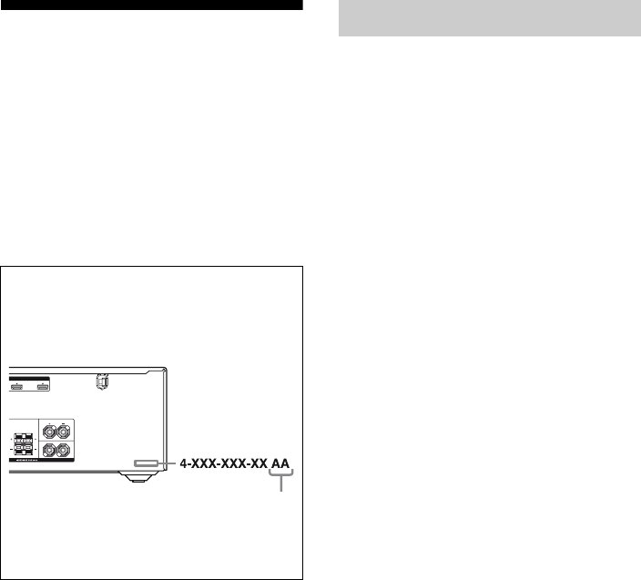
About area codes
The area code of the receiver you purchased is
shown on the lower right portion of the rear panel
(see the illustration below).
Any differences in operation, according to the area
code, are clearly indicated in the text, for example,
“Models of area code AA only”.
HDMI
BD IN OUT
SURROUND
FRONT A
L
R
LR
A
KERS
Area code
On Copyrights

5US
Table of Contents
Description and location of parts .................. 7
Getting Started
1: Installing the speakers............................. 17
2: Connecting the speakers ......................... 18
3: Connecting the TV.................................. 20
4a: Connecting the audio components ........ 21
4b: Connecting the video components ........ 22
5: Connecting the antennas (aerials) ........... 28
6: Preparing the receiver and the remote..... 29
7: Selecting the speaker system .................. 30
8: Calibrating the appropriate settings
automatically
(AUTO CALIBRATION) ...................... 31
9: Adjusting the speaker levels and
balance (TEST TONE)........................... 35
Playback
Selecting a component ................................ 36
Listening/Watching a component................ 38
Amplifier Operations
Navigating through menus .......................... 40
Adjusting the level (LEVEL menu) ............ 45
Adjusting the equalizer (EQ menu) ............ 46
Settings for the surround sound
(SUR menu) ........................................... 46
Settings for the tuner (TUNER menu) ........ 48
Settings for the audio (AUDIO menu) ........ 49
Settings for the HDMI (HDMI menu) ........ 50
Settings for the system (SYSTEM menu)... 51
Calibrating the appropriate settings
automatically (A. CAL menu) ............... 55
Settings for the S-AIR (S. AIR menu) ........ 56
Enjoying Surround Sound
Enjoying Dolby Digital and DTS Surround
sound (AUTO FORMAT DIRECT) .......56
Selecting a pre-programmed sound field.....58
Using only the front speakers
(2CH STEREO)......................................60
Listening to the sound without any
adjustment (ANALOG DIRECT)...........61
Resetting sound fields to the initial
settings....................................................61
Tuner Operations
Listening to FM/AM radio ..........................62
Presetting FM/AM radio stations ................64
Listening to Satellite Radio .........................66
Connecting the SIRIUS Satellite Radio ......67
Preparing to listen to the SIRIUS
Satellite Radio ........................................67
Selecting a channel of the SIRIUS
Satellite Radio ........................................69
Presetting SIRIUS Satellite Radio
channels..................................................70
Restricting access to specific channels
(Parental Lock) (SIRIUS only)...............72
“BRAVIA” Sync Features
What is “BRAVIA” Sync?...........................75
Preparing for the “BRAVIA” Sync..............76
Watching a DVD (One-Touch Play)............77
Enjoying the TV sound from the speakers
connected to the receiver
(System Audio Control) .........................78
Turning off the receiver with the TV
(System Power Off)................................79

6US
S-AIR Operations
About S-AIR products.................................80
Setting up an S-AIR product .......................81
Enjoying the system’s sound in another
room........................................................85
Changing the channel for better sound
transmission............................................86
Enjoying the S-AIR receiver while the
S-AIR main unit is in standby mode ......87
Other Operations
Switching between digital and analog
audio (INPUT MODE)...........................88
Listening to digital sound from other
inputs (DIGITAL ASSIGN) ...................89
Enjoying the DIGITAL MEDIA PORT
(DMPORT) .............................................90
Changing the display ...................................92
Using the Sleep Timer .................................93
Recording using the receiver .......................93
Using a bi-amplifier connection ..................94
Using the Remote
Changing button assignments......................96
Additional Information
Glossary.......................................................97
Precautions ..................................................99
Troubleshooting.........................................101
Specifications.............................................106
Index ..............................................Back cover
7US
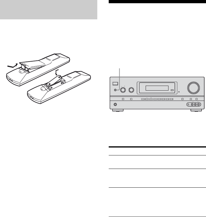
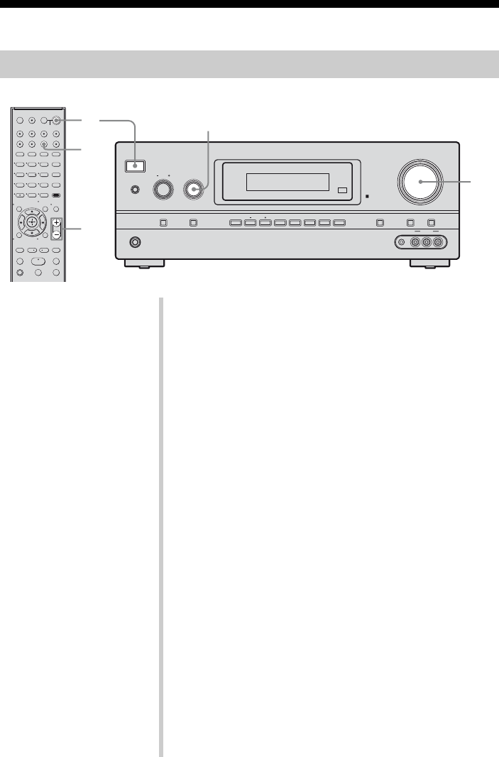
Description and location of parts
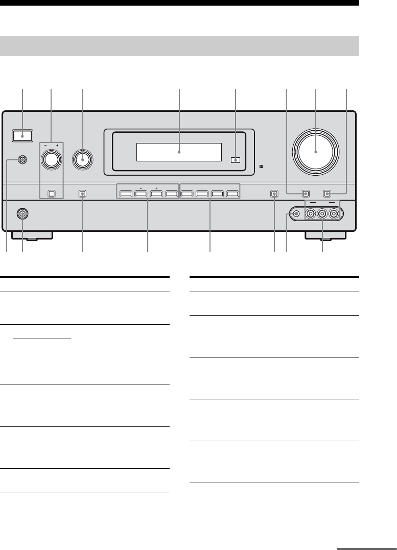
Front panel
?/1
PHONES
SPEAKERS
INPUT SELECTOR
INPUT MODE TUNING MODE
MASTER VOLUME
TONE MODE DISPLAY DIMMER MUTING
MEMORY/
ENTER 2CH/
A.DIRECT A.F.D. MOVIE MUSICTUNING
TONE
VIDEO 2 IN
VIDEO L AUDIO R
AUTO CAL MIC
9
q;
qa
qf qs
8
qd
132456
qh qg
7
Name Function
A?/1
(on/standby)
Press to turn the receiver on
or off (page 29, 38, 39, 61,
63).
BTONE +/– Adjust the bass and treble for
the front channels. Press
TONE MODE repeatedly to
select BASS or TREBLE,
then turn TONE +/– to adjust
the level (page 41).
TONE MODE
CINPUT
SELECTOR
Turn to select the input
source to play back (page 36,
37, 38, 39, 61, 62, 64, 65, 68,
88, 92, 93, 94).
DDisplay The current status of the
selected component or a list
of selectable items appears
here (page 9).
ERemote
sensor
Receives signals from remote
commander.
Name Function
FDIMMER Press repeatedly to adjust the
brightness of the display.
GMASTER
VOLUME
Turn to adjust the volume
level of all speakers at the
same time (page 35, 36, 38,
39).
HMUTING Press to turn off the sound
temporarily.
Press MUTING again to
restore the sound (page 36).
IVIDEO 2 IN
jacks
Connects to a portable audio/
video component such as a
camcorder or video game
(page 27, 36).
JAUTO CAL
MIC jack
Connects to the supplied
optimizer microphone for the
Auto Calibration function
(page 31).
continued

8US
Name Function
KDISPLAY Press to select information
displayed on the display
(page 92).
L2CH/
A.DIRECT
Press to select a sound field
(page 56, 58).
A.F.D.
MOVIE
MUSIC
MTUNING
MODE
Press to operate a tuner (FM/
AM) and satellite radio
(SIRIUS) (page 62, 68).
TUNING +/–
MEMORY/
ENTER
NINPUT MODE Press to select the input mode
when the same components
are connected to both digital
and analog jacks (page 88).
OPHONES jack Connects to headphones
(page 101).
PSPEAKERS Press to select the front
speaker system (page 30).
9US
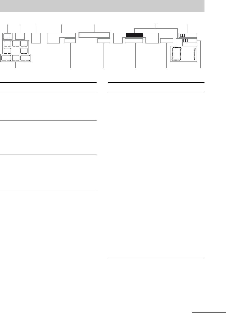
About the indicators on the display
SW
LFE
SP A
SP B
LC
SL S
PL IIxOPT HDMI CATDTS -ES 96/24 MEMORY
MONO SLEEP STD.RANGES-AIRCOAX NEO:6 SAT
SB
SBL
R
SR
SBR
DEX
1 2 3 4 5 7
qd q; 9qaqs 8
6
Name Function
ASW Lights up when subwoofer
selection is set to “YES” (page
51) and the audio signal is
output from the SUBWOOFER
jack.
BLFE Lights up when the disc being
played back contains an LFE
(Low Frequency Effect)
channel and the LFE channel
signal is actually being
reproduced.
CSP A/SP B Lights up according to the
speaker system used. However,
these indicators do not light up
if the speaker output is turned
off or if headphones are
connected.
Name Function
D Input
indicators
OPT
COAX
HDMI
Light up to indicate the current
input.
Lights up when INPUT MODE
is set to “AUTO” and the
source signal is a digital signal
being input through the
OPTICAL jack or when
INPUT MODE is set to “OPT”.
However, “NO INPUT”
appears on the display when
INPUT MODE is set to “OPT”
and no digital signal is input
through the OPTICAL jack
(page 88).
Lights up when INPUT MODE
is set to “AUTO” and the
source signal is a digital signal
being input through the
COAXIAL jack or when
INPUT MODE is set to
“COAX”. However, “NO
INPUT” appears on the display
when INPUT MODE is set to
“COAX” and no digital signal
is input through the COAXIAL
jack (page 88).
Lights up when the receiver
recognizes a component
connected via an HDMI IN
jacks (page 23).
continued
10US
Name Function
EDTS(-ES)
indicators
DTS
DTS-ES
DTS 96/24
Light up when DTS or DTS-ES
signals are input.
Lights up when the receiver is
decoding DTS signals.
Lights up when the receiver is
decoding DTS-ES signals.
Lights up when the receiver is
decoding DTS 96/24 (96 kHz/
24 bit) signals.
Note
When playing a DTS format
disc, be sure that you have
made digital connections and
that INPUT MODE is not set to
“ANALOG” (page 88).
FTuning
indicators
CAT
SAT
MEMORY
MONO
ST
Lights up when the receiver
tunes in radio stations, or
satellite radio stations.
Lights up when the category
mode is set to “ONE CAT”
during the satellite radio
operation.
Lights up when the
SiriusConnect Home tuner is
connected and “SIRIUS” is
selected.
Lights up when a memory
function, such as Preset
Memory (page 65), etc., is
activated.
Monaural broadcast
Stereo broadcast
A preset station number
appears when the preset radio
station is selected.
Note
The preset station number will
change according to the preset
station you select. For details
on presetting radio stations, see
page 64.
Name Function
GDolby
Pro Logic
indicators
PL
PLII
PLIIx
Lights up one of the respective
indicators when the receiver
applies Dolby Pro Logic
processing to 2 channel signals
in order to output the center and
surround channel signals.
Dolby Pro Logic
Dolby Pro Logic II
Dolby Pro Logic IIx
Notes
• These indicators do not light
up if both the center and
surround speakers are set to
“NO” (page 43) and you
select a sound field using the
A.F.D. button.
• Dolby Pro Logic IIx
decoding does not function
for DTS format signals or for
signals with a sampling
frequency of more than
48 kHz.
HDolby
Digital
Surround
indicators
D
DEX
Lights up one of the respective
indicators when the receiver is
decoding the corresponding
Dolby Digital format signals.
Dolby Digital
Dolby Digital Surround EX
Note
When playing a Dolby Digital
format disc, be sure that you
have made digital connections
and that INPUT MODE is not
set to “ANALOG” (page 88).
ISLEEP Lights up when the sleep timer
is activated.
JD.RANGE Lights up when dynamic range
compression is activated (page
41).
KNEO:6 Lights up when DTS Neo:6
Cinema/Music decoder is
activated (page 57).
LS-AIR Lights up when the S-AIR
transmitter (not supplied) is
connected.

11US
Name Function
MPlayback
channel
indicators
L
R
C
SL
SR
S
SBL
SBR
SB
The letters (L, C, R, etc.)
indicate the channels being
played back. The boxes around
the letters vary to show how the
receiver downmixes the source
sound (based on the speaker
settings).
Front Left
Front Right
Center (monaural)
Surround Left
Surround Right
Surround (monaural or the
surround components obtained
by Pro Logic processing)
Surround Back Left
Surround Back Right
Surround Back (the surround
back components obtained by
6.1 channel decoding)
Example:
Recording format (Front/
Surround): 3/2.1
Output channel: When
surround speakers are set to
“NO” (page 43)
Sound Field: A.F.D. AUTO
SW
LCR
SL SR
12US
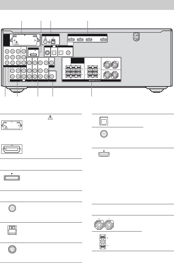
Rear panel
5668 7
12 3 4
L
R
DIGITAL
(ASSIGNABLE)
DC5V
0.7A MAX
HDMIANTENNA
DMPORT
SIRIUS
SAT IN
SAT
IN
DVD IN BD IN OUT
AM
CENTER SURROUND
FRONT A
L
L
R
R LR
Y
P
B
/
C
B
COMPONENT VIDEO
OUT IN
P
R
/
C
R
DVD
IN
VIDEO 1
IN
MONITOR
OUT
SA-CD
/
CD
/
CD-R
VIDEO 1
IN
TV
TV
AUDIO
IN
VIDEO
IN
SAT
AUDIO
OUT
AUDIO
OUT
VIDEO
OUT
VIDEO
OUT
IN
OPTICAL
AUDIO
IN
VIDEO
IN
SUBWOOFER
MONITOR
AUDIO
IN
VIDEO
IN
BD
SPEAKERS
SURROUND BACK
/
BI-AMP
/
FRONT B
SAT
IN
DVD
IN
OPTICAL COAXIAL
EZW-T100
AS-AIR (EZW-T100)
CAUTION
Please do not remove
the slot cover until
you want to install the
wireless transmitter.
Connects to a
wireless transmitter
(not supplied) (page
81).
BDMPORT
DMPORT
jack
Connects to a
DIGITAL MEDIA
PORT adapter (page
91).
CANTENNA section
FM
ANTENNA
jack
Connects to the
supplied FM wire
antenna (aerial)
(page 28).
AM
ANTENNA
terminals
Connects to the
supplied AM loop
antenna (aerial)
(page 28).
SIRIUS jack Connects to a
SiriusConnect Home
tuner (not supplied)
(page 67).
With slot cover
slot
DDIGITAL INPUT/OUTPUT section
OPTICAL
IN jacks
Connects to a
DVD player, etc.
The COAXIAL
jack provides a
better sound
quality (page 25,
26).
COAXIAL IN
jack
HDMI IN/
OUT* jacks
Connects to a
DVD player,
satellite tuner, or a
Blu-ray disc
player. The image
is output to a TV or
a projector while
the sound can be
output from a TV
or/and speakers
connected to this
receiver (page 23).
ESPEAKERS section
Connects to the
speakers (page 18).
13US
* You can watch the selected input image when you
connect the MONITOR OUT or HDMI OUT jack
to a TV or projector (page 20).
You can use the supplied RM-AAU021
Remote Commander to operate the receiver
and to control the Sony audio/video
components that the remote is assigned to
operate (page 96).
FAUDIO INPUT/OUTPUT section
AUDIO IN/
OUT jacks
Connects to a Super
Audio CD player,
CD recorder, etc.
(page 21).
AUDIO OUT
jack
Connects to a
subwoofer (page
18).
GVIDEO/AUDIO INPUT/OUTPUT
section
AUDIO IN/
OUT jacks
Connects to a VCR,
Blu-ray disc player,
etc. (page 20–27).
VIDEO IN/
OUT* jacks
HCOMPONENT VIDEO INPUT/
OUTPUT section
Y, PB/CB,
PR/CR IN/
OUT* jacks
Connects to a DVD
player, TV, satellite
tuner, etc. You can
enjoy high quality
image (page 20–
27).
White (L)
Red (R)
Black
White (L)
Red (R)
Yellow
Green
(Y)
Blue
(PB/CB)
Red
(PR/CR)
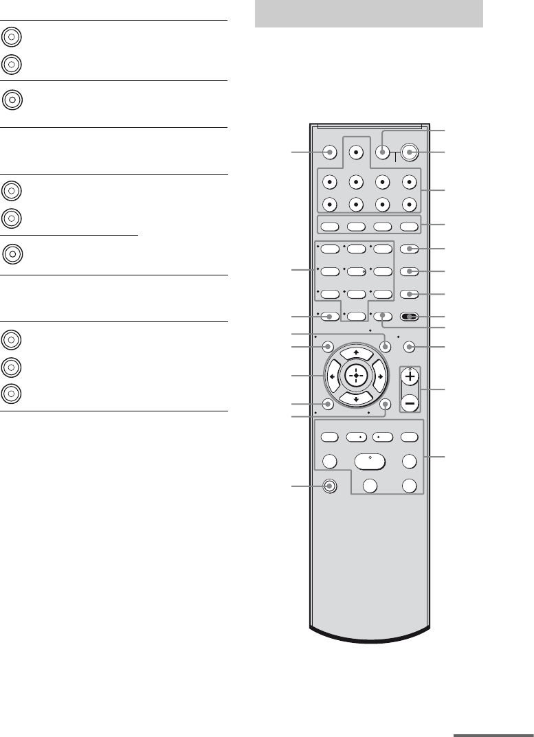
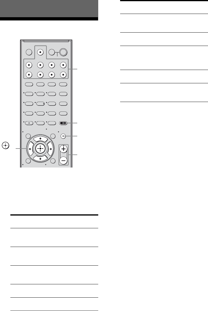
Remote commander
123
46
78
0/10
ENTER
9
SYSTEM STANDBY
TV INPUT
SLEEP DMPORT
VIDEO1 VIDEO2 BD DVD
2CH A.F.D.
TV CH –
PRESET –
TV CH +
PRESET +
TUNING –
TV
TUNING +
FM MODE
MOVIE MUSIC
AMP MENU
CLEAR
DISPLAY MUTING
TV VOL
MASTER VOL
DVD/BD
MENU
AUTO CAL
D.TUNING
D.SKIP
THEATER
SAT TV SA-CD/CD TUNER
?/1
.
HmM
Xx
<
<
>
5
>10
REPLAY ADVANCE
– CATEGORY +
CATEGORY MODE
MEMORY
O
RETURN/EXIT
qg
qj
qk
qh
ql
w;
wa
qd
1
3
2
5
6
7
8
q;
9
qs
qa
4
qf
TV
?/1
AV
?/1
TOOLS/
OPTIONS
MENU/HOME
continued
14US
Name Function
ATV ?/1
(on/standby)
Press TV ?/1 and TV (M) at
the same time to turn the TV
on or off.
AV ?/1
(on/standby)
Press to turn on or off the
Sony audio/video components
that the remote is assigned to
operate (page 96).
If you press ?/1 (B) at the
same time, it will turn off the
receiver and other Sony
components (SYSTEM
STANDBY).
Note
The function of the AV ?/1
switch changes automatically
each time you press the input
buttons (C).
B?/1
(on/standby)
Press to turn the receiver on or
off.
To turn off all Sony
components, press ?/1 and
AV ?/1 (A) at the same time
(SYSTEM STANDBY).
CInput buttons Press one of the buttons to
select the component you
want to use. When you press
any of the input buttons, the
receiver turns on. The buttons
are factory assigned to control
Sony components.
You can change the button
assignments following the
steps in “Changing button
assignments” on page 96.
D2CH Press to select a sound field.
A.F.D.
MOVIE
MUSIC
ETHEATER Press to enjoy optimal image
suited for movies and to
output the sound from the
speakers connected to this
receiver automatically.
Note
This button will only function
if your TV is compatible with
Theater Mode.
Refer to the operating
instructions supplied with the
TV for details.
Name Function
FDVD/BD
MENU
Press to display the menu of
the DVD or Blu-ray disc on
the TV screen. Then, use V, v,
B, b and (P) to perform
menu operations.
AUTO CAL Press to activate the Auto
Calibration function.
GD.TUNING Press to enter direct tuning
mode.
D.SKIP Press to skip a disc when
using a multi-disc changer.
HAMP MENU Press to display the menu of
the receiver. Then, use V, v,
B, b and (P) to perform
menu operations.
IENTER Press to enter the value after
selecting a channel, disc or
track using the numeric
buttons of the TV, VCR or
satellite tuner.
MEMORY Press to store a station.
JMUTING Press to turn off the sound
temporarily.
Press MUTING again to
restore the sound.
Press MUTING and TV (M)
at the same time to activate
the TV’s muting function.
KTV VOL
+a)/–
Press TV VOL +/– and TV
(M) at the same time to adjust
the volume level of the TV.
MASTER
VOL +a)/–
Press to adjust the volume
level of all speakers at the
same time.
L./>b) Press to skip a track of the CD
player, DVD player or Blu-
ray disc player.
REPLAY /
ADVANCE
Press to replay the previous
scene or fast forward the
current scene of the VCR,
DVD player or Blu-ray disc
player.
m/Mb) Press to
– search tracks in the forward/
reverse direction of the
DVD player.
– start fast forward/rewind of
the VCR, CD player or Blu-
ray disc player.
<
<
15US
Name Function
Ha)b) Press to start playback of the
VCR, CD player, DVD player,
or Blu-ray disc player.
Xb) Press to pause playback or
recording of the VCR, CD
player, DVD player or Blu-ray
disc player. (Also starts
recording with components in
recording standby.)
xb) Press to stop playback of the
VCR, CD player, DVD player
or Blu-ray disc player.
TV CH +/– Press TV CH +/– and TV (M)
at the same time to select
preset TV channels.
CATEGORY
+/–
Press to select a category for
SIRIUS Satellite Radio (page
69).
PRESET +/– Press to select
– preset stations.
– preset channels of the VCR
or satellite tuner.
TUNING +/– Press to scan a station.
CATEGORY
MODE
Press to select the category
mode for satellite tuner
(page 69).
FM MODE Press to select the FM
monaural or stereo reception.
MTV Press TV and the button with
orange printing at the same
time to enable TV operation.
NMENU/HOME Press to display the menu of
the VCR, DVD player,
satellite tuner or Blu-ray disc
player on the TV screen.
Press MENU/HOME and TV
(M) at the same time to
display the TV’s menu.
Then, use V, v, B, b and
(P) to perform menu
operations.
Name Function
ORETURN/
EXIT OPress to
– return to the previous menu.
– exit the menu while the
menu or on-screen guide of
the VCR, DVD player,
satellite tuner or Blu-ray
disc player is displayed on
the TV screen.
Press RETURN/EXIT O
and TV (M) at the same time
to return to the previous menu
or exit the TV’s menu while
the menu is displayed on the
TV screen.
P
V/v/B/b
After pressing DVD/BD
MENU (F), AMP MENU
(H), or MENU/HOME (N),
press V, v, B or b to select the
settings. Then, press to
enter the selection if you have
pressed DVD/BD MENU or
MENU/HOME previously.
Press also to enter the
selection of the receiver,
VCR, satellite tuner, CD
player, DVD player or Blu-
ray disc player.
QDISPLAY Press to select information
displayed on the TV screen of
the VCR, satellite tuner, CD
player, DVD player or Blu-
ray disc player.
Press DISPLAY and TV (M)
at the same time to display
TV’s information on the TV
screen.
RTOOLS/
OPTIONS
Press to display and select the
options of the DVD player or
Blu-ray disc player.
Press TOOLS/OPTIONS and
TV (M) at the same time to
display the options applicable
to the Sony TV.
continued

16US
a)The number 5, MASTER VOL +, TV VOL +, and
H buttons have tactile dots. Use the tactile dots
as references when operating the receiver.
b)This button is also available for DIGITAL MEDIA
PORT adapter operation. For details on the
function of the button, refer to the operating
instructions supplied with the DIGITAL MEDIA
PORT adapter.
Notes
• Some functions explained in this section may not
work depending on the model.
• The above explanation is intended to serve as an
example only. Therefore, depending on the
component, the above operation may not be
possible or may operate differently than described.
Name Function
SzPress to input the decimal
point for channel numbers of
the Digital CATV terminal.
Press z and TV (M) at the
same time to input the decimal
point for the channel numbers
of the TV.
>10 Press to select track numbers
over 10 of the CD player.
CLEAR Press to clear a mistake when
you press the incorrect
numeric button.
TNumeric
buttons
(number 5a))
Press to
– preset/tune to preset
stations.
– select track numbers of the
CD player, DVD player or
Blu-ray disc player. Press
0/10 to select track number
10.
– select channel numbers of
the VCR or satellite tuner.
Press the numeric buttons and
TV (M) at the same time to
select the TV channels.
UTV INPUT Press TV INPUT and TV (M)
at the same time to select the
input signal (TV input or
video input).
SLEEP Press to activate the Sleep
Timer function and the
duration which the receiver
turns off automatically.
17US
Getting Started
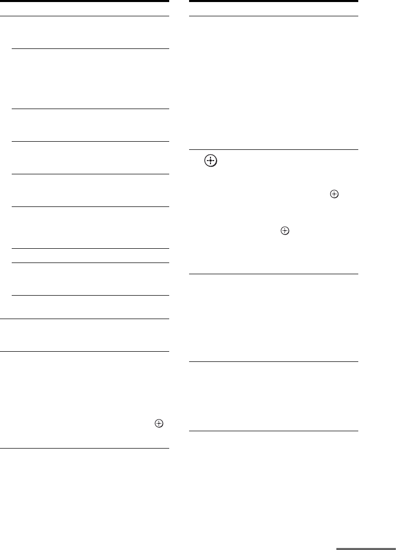
1: Installing the speakers
This receiver allows you to use a 7.1 channel
system (7 speakers and one subwoofer).
To fully enjoy theater-like multi channel
surround sound requires five speakers (two
front speakers, a center speaker, and two
surround speakers) and a subwoofer (5.1
channel).
Example of a 5.1 channel
speaker system configuration
AFront speaker (left)
BFront speaker (right)
CCenter speaker
DSurround speaker (left)
ESurround speaker (right)
HSubwoofer
You can enjoy high fidelity reproduction of
DVD software recorded sound in the Surround
EX format if you connect one additional
surround back speaker (6.1 channel system) or
two surround back speakers (7.1 channel
system). See “Using the surround back
decoding mode (SB DEC)” (page 47).
Example of a 7.1 channel
speaker system configuration
AFront speaker (left)
BFront speaker (right)
CCenter speaker
DSurround speaker (left)
ESurround speaker (right)
FSurround back speaker (left)
GSurround back speaker (right)
HSubwoofer
Tips
• When you connect a 6.1 channel speaker system,
place the surround back speaker behind the
listening position.
• Since the subwoofer does not emit highly
directional signals, you can place it wherever you
want.
Getting Started
Enjoying a 5.1/7.1 channel
system
18US
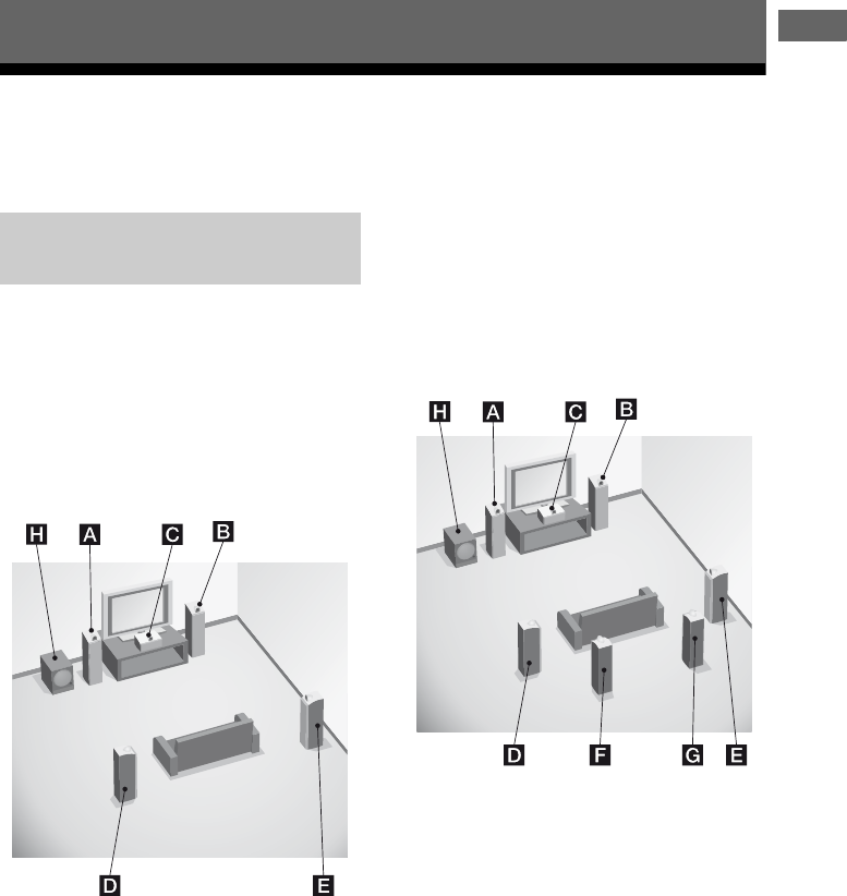
2: Connecting the speakers
Before connecting the cords, be sure to
disconnect the AC power cord (mains lead).
AFront speaker A (left)
BFront speaker A (right)
CCenter speaker
DSurround speaker (left)
ESurround speaker (right)
FSurround back speaker (left)a)b)c)
GSurround back speaker (right)a)b)c)
HSubwooferd)
13/32 in.
(10 mm)
DIGITAL
(ASSIGNABLE)
D
C5V
0
.7A MAX
HDMIANTENNA
M
PORT
SIRIUS
SAT IN DVD IN BD IN OUT
AM
VIDEO 1
TV
AUDIO
OUT
VIDEO
OUT
VIDEO
OUT
IN
OPTICAL
AUDIO
IN
VIDEO
IN
MONITOR
AUDIO
IN
VIDEO
IN
BD
SAT
IN
DVD
IN
OPTICAL COAXIAL
SUBWOOFER
L
L
R
R L
SPEAKERS
CENTER SURROUND
FRONT A
R
SURROUND BACK
/
BI-AMP
/
FRONT B
AUDIO
OUT
H
FDC
A
AMonaural audio cord (not supplied)
BSpeaker cords (not supplied)
E
B
B
GA
B

19US
Getting Started
a) If you connect only one surround back speaker,
connect it to the SPEAKERS SURROUND
BACK/BI-AMP/FRONT B L terminals.
b)If you are not using surround back speaker, and
you have an additional front speaker system,
connect the additional front speaker system to the
SPEAKERS SURROUND BACK/BI-AMP/
FRONT B terminals. Set “SB ASGN” to “SPK B”
in the System settings menu (page 43).
You can select the front speaker system you want
to use with SPEAKERS on the front panel
(page 30).
c) If you are not using surround back speakers, you
can connect the front speakers to the SPEAKERS
SURROUND BACK/BI-AMP/FRONT B
terminals using a bi-amplifier connection
(page 94).
Set “SB ASGN” to “BI-AMP” in the System
settings menu (page 43).
d)When you connect a subwoofer with an auto
standby function, turn off the function when
watching movies. If the auto standby function is
set to on, it turns to standby mode automatically
based on the level of the input signal to a
subwoofer, then sound may not be output.
20US
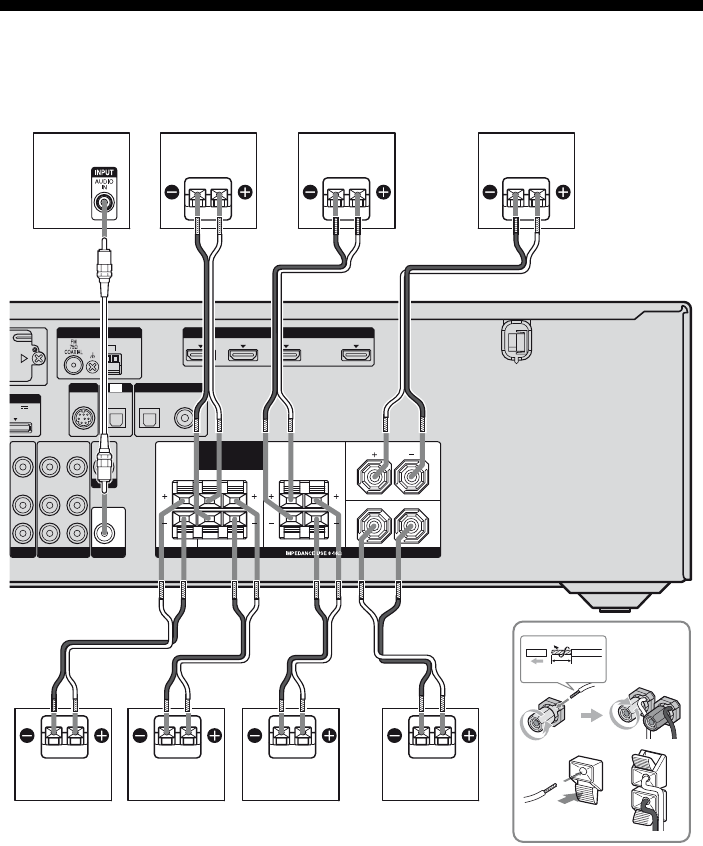
3: Connecting the TV
You can watch the selected input image when
you connect the HDMI OUT or MONITOR
OUT jack to a TV.
It is not necessary to connect all the cords.
Connect audio and video cords according to
the jacks of your components.
Before connecting the cords, be sure to
disconnect the AC power cord (mains lead).
L
R
DIGITAL
(ASSIGNABLE)
DC5V
0.7A MAX
ANTENNA
DMPORT
SIRIUS
AM
CENTER SURROUND
FRONT A
L
L
R
RLR
OUT IN
SA-CD
/
CD
/
CD-R
VIDEO 1
TV
AUDIO
IN
VIDEO
IN
SAT
AUDIO
OUT
AUDIO
OUT
VIDEO
OUT
IN
OPTICAL
AUDIO
IN
VIDEO
IN
SUBWOOFER
AUDIO
IN
VIDEO
IN
BD
SPEAKERS
SURROUND BACK
/
BI-AMP
/
FRONT B
SAT
IN
DVD
IN
OPTICAL COAXIAL
EZW-T100
VIDEO
OUT
MONITOR
IN
TV
Y
P
B
/
C
B
COMPONENT VIDEO
P
R
/
C
R
MONITOR
OUT
HDMI
SAT IN DVD IN BD IN OUT
SAT
IN
DVD
IN
VIDEO 1
IN
TV
BCD
AComponent video cord (not supplied)
BVideo cord (not supplied)
COptical digital cord (not supplied)
DAudio cord (not supplied)
EHDMI cable (not supplied)
We recommend that you use a Sony HDMI cable.
Audio/video
signals
Video signals
A
Audio signals
E
21US
Getting Started
Notes
• Be sure to turn on the receiver when the video and
audio signals of a playback component are being
output to a TV via the receiver. Unless the power is
turned on, neither video nor audio signals will be
transmitted.
• When connecting optical digital cords, insert the
plugs straight in until they click into place.
• Do not bend or tie optical digital cords.
Tips
• To output the sound of the TV from the speakers
connected to the receiver, be sure to
– connect the audio output jacks of the TV to the
TV IN jacks of the receiver.
– turn off the TV’s volume or activate the TV’s
muting function.
• All the digital audio jacks are compatible with
32 kHz, 44.1 kHz, 48 kHz, and 96 kHz sampling
frequencies.
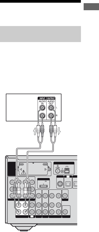
4a: Connecting the audio
components
The following illustration shows how to
connect a Super Audio CD player, CD player
or CD recorder.
Before connecting the cords, be sure to
disconnect the AC power cord (mains lead).
After connecting your audio component,
proceed to “4b: Connecting the video
components”(page 22).
Connecting a Super Audio CD/
CD player or CD recorder
DIG
DC5V
0.7A MAX
ANTENNA
DMPORT
SIRIUS
SAT
IN
AM
Y
P
B
/
C
B
P
R
/
C
R
DVD
IN
VIDEO 1
IN
MONITOR
OUT
VIDEO 1
IN
TV
TV
AUDIO
IN
VIDEO
IN
SAT
AUDIO
OUT
AUDIO
OUT
VIDEO
OUT
VIDEO
OUT
IN
OPTICAL
AUDIO
IN
VIDEO
IN
SUBWOOFER
MONITOR
AUDIO
IN
VIDEO
IN
BD
OPTIC
EZW-T100
R
SA-CD
/
CD
/
CD-R
COMPONENT VIDEO
L
OUT IN
Super Audio CD
player/CD player/
CD recorder
A
AAudio cord (not supplied)
22US
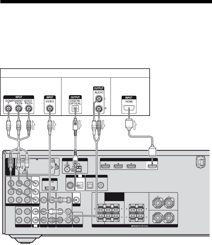
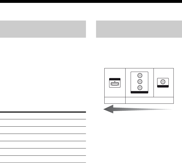
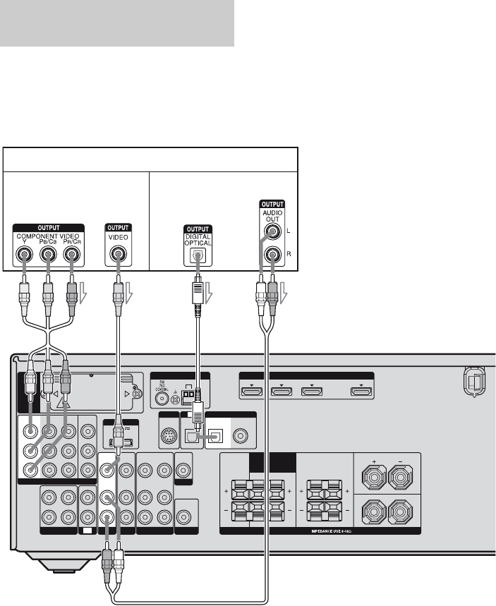
4b: Connecting the video components
This section describes how to connect your
video components to this receiver. Before you
begin, refer to “Component to be connected”
below for the pages which describe how to
connect each component.
Before connecting the cords, be sure to
disconnect the AC power cord (mains lead).
After connecting all your components,
proceed to “5: Connecting the antennas
(aerials)” (page 28).
Component to be connected
If you want to connect several
digital components, but cannot
find an unused input
See “Listening to digital sound from other
inputs (DIGITAL ASSIGN)” (page 89).
The image quality depends on the connecting
jack. Refer to the illustration that follows.
Select the connection according to the jacks on
your components.
Note
Be sure to turn on the receiver when the video and
audio signals of a playback component are being
output to a TV via the receiver. Unless the power is
turned on, neither video nor audio signals will be
transmitted.
How to connect your
components
Component Page
TV 20
With HDMI jack 23
DVD player/Blu-ray disc player 25
Satellite tuner/Set-top box 26
DVD recorder, VCR 27
Camcorder, video game, etc. 27
Video input/output jacks to be
connected
HDMI
VIDEO
COMPONENT VIDEO
Y
P
B
/
C
B
P
R
/
C
R
Digital Analog
High quality image
23US
Getting Started
HDMI is the abbreviated name for High-
Definition Multimedia Interface. It is an
interface which transmits video and audio
signals in digital format.
To enjoy TV multi channel
surround sound broadcasting
You can listen to TV multi channel surround
sound broadcasting from the speakers
connected to the receiver.
Connect the OPTICAL output jack of the TV
to the OPTICAL IN jack of the receiver.
* Connect at least one of the audio cords (B or C).
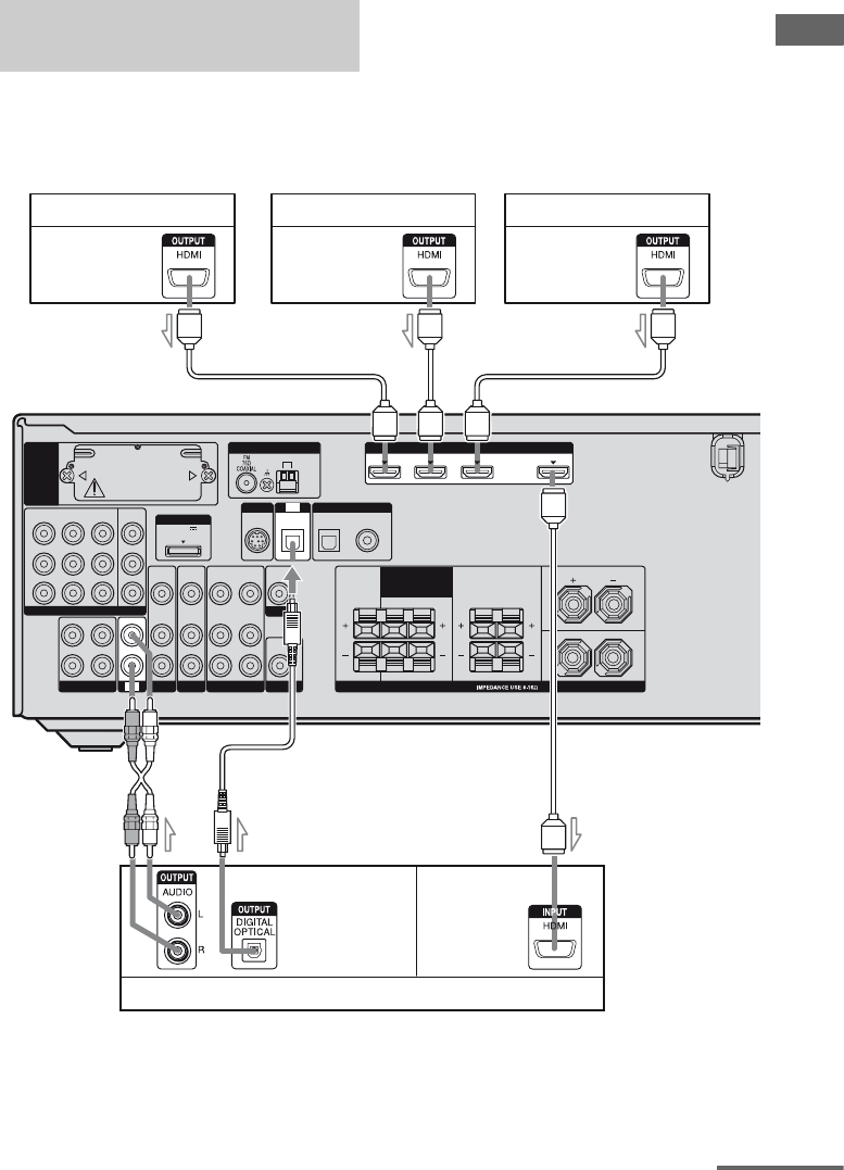
Connecting components with
HDMI jacks
L
R
DIGITAL
(ASSIGNABLE)
DC5V
0.7A MAX
ANTENNA
DMPORT
SIRIUS
SAT
IN
OUT
AM
CENTER SURROUND
FRONT A
L
L
R
R LR
Y
P
B
/
C
B
COMPONENT VIDEO
OUT IN
P
R
/
C
R
DVD
IN
VIDEO 1
IN
MONITOR
OUT
SA-CD
/
CD
/
CD-R
VIDEO 1
TV
AUDIO
IN
VIDEO
IN
SAT
AUDIO
OUT
AUDIO
OUT
VIDEO
OUT
VIDEO
OUT
IN
AUDIO
IN
VIDEO
IN
SUBWOOFER
MONITOR
AUDIO
IN
VIDEO
IN
BD
SPEAKERS
SURROUND BACK
/
BI-AMP
/
FRONT B
SAT
IN
DVD
IN
OPTICAL COAXIAL
EZW-T100
IN
SAT IN DVD IN BD IN
OPTICAL
TV
HDMI
Satellite tuner/Set-top box
AHDMI cable (not supplied)
We recommend that you use a Sony HDMI cable.
BOptical digital cord (not supplied)*
CAudio cord (not supplied)*
DVD player Blu-ray disc player
Audio/video
signals
Audio/video
signals
Audio/video
signals
Audio signals
TV, etc.
Audio/video
signals
AAA
ABC
continued
24US
HDMI features
• A digital audio signal transmitted by HDMI
can be output from the speakers connected to
this receiver. This signal supports Dolby
Digital, DTS, and Linear PCM.
• The receiver supports xvYCC transmission.
• This receiver supports the Control for HDMI
function. For details, see ““BRAVIA” Sync
Features” (page 75).
Notes on HDMI connections
• An audio signal input to the HDMI IN jack
is output from the speaker output jack and
HDMI OUT jack. It is not output from any
other audio jacks.
• Video signals input to the HDMI IN jack can
only be output from the HDMI OUT jack.
The video input signals cannot be output
from the VIDEO OUT jacks or MONITOR
OUT jacks.
• When you want to listen to the sound from
the TV speaker, set “AUDIO FOR HDMI” to
“TV+AMP” in the HDMI menu (page 42). If
you cannot play back multi channel
software, set to “AMP”. However, the sound
will not output from the TV speaker.
• The multi/stereo area audio signals of a
Super Audio CD are not output.
• Audio signals (sampling frequency, bit
length, etc.) transmitted from an HDMI jack
may be suppressed by the connected
component. Check the setup of the
connected component if an image is poor or
the sound does not come out of a component
connected via the HDMI cable.
• Sound may be interrupted when the
sampling frequency, the number of channels
or the audio format of the audio output
signals from the playback component is
switched.
• When the connected component is not
compatible with copyright protection
technology (HDCP), the image and/or the
sound from the HDMI OUT jack may be
distorted or may not be output.
In this case, check the specification of the
connected component.
• You can enjoy multi channel Linear PCM
only with an HDMI connection.
• Set the image resolution of the playback
component to 720p,1080i or 1080p when
you output 96 kHz multi-channel sound over
an HDMI connection.
• You may need to make certain settings on the
image resolution of the player before you
can enjoy multi channel Linear PCM. Refer
to the operating instructions of the player.
• Refer to the operating instructions of each
component connected for details.
• We do not recommend using an HDMI-DVI
conversion cable. When you connect an
HDMI-DVI conversion cable to a DVI-D
component, the sound and/or the image may
not be output.
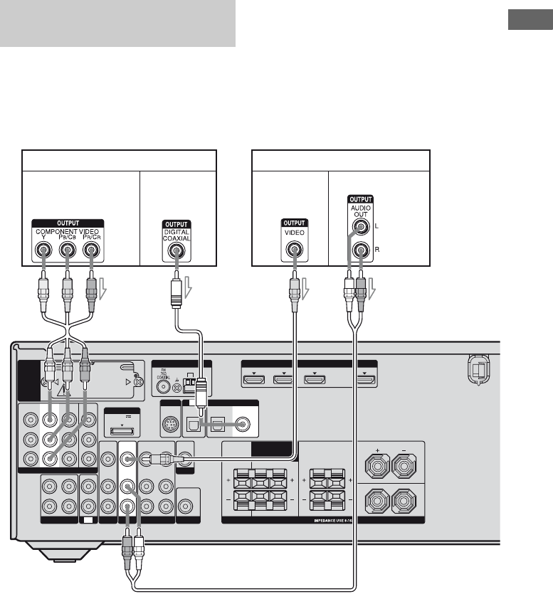
25US
Getting Started
The following illustration shows how to
connect a DVD player or a Blu-ray disc player.
It is not necessary to connect all the cords.
Connect audio and video cords according to
the jacks of your components.
Note
To input multi channel digital audio from the DVD
player, set the digital audio output setting on the
DVD player. Refer to the operating instructions
supplied with the DVD player.
Tip
All the digital audio jacks are compatible with
32 kHz, 44.1 kHz, 48 kHz, and 96 kHz sampling
frequencies.
Connecting a DVD player/
Blu-ray disc player
L
R
DC5V
0.7A MAX
HDMIANTENNA
DMPORT
SIRIUS
SAT IN DVD IN BD IN OUT
AM
CENTER SURROUND
FRONT A
L
L
R
RLR
OUT IN
SA-CD
/
CD
/
CD-R
VIDEO 1
IN
TV
TV
AUDIO
IN
VIDEO
IN
SAT
AUDIO
OUT
AUDIO
OUT
VIDEO
OUT
VIDEO
OUT
IN
OPTICAL
AUDIO
IN
VIDEO
IN
SUBWOOFER
MONITOR
SPEAKERS
SURROUND BACK
/
BI-AMP
/
FRONT B
EZW-T100
AUDIO
IN
VIDEO
IN
DIGITAL
(ASSIGNABLE)
DVD
IN
OPTICAL COAXIAL
SAT
IN
Y
P
B
/
C
B
COMPONENT VIDEO
P
R
/
C
R
DVD
IN
VIDEO 1
IN
MONITOR
OUT
BD
SAT
IN
DVD player
AB D
AComponent video cord (not supplied)
BCoaxial digital cord (not supplied)
CVideo cord (not supplied)
DAudio cord (not supplied)
Video signals Audio signals
C
Blu-ray disc player
Video signals Audio signals
26US
The following illustration shows how to
connect a satellite tuner or a set-top box.
It is not necessary to connect all the cords.
Connect audio and video cords according to
the jacks of your components.
Notes
• When connecting optical digital cords, insert the
plugs straight in until they click into place.
• Do not bend or tie optical digital cords.
Tip
All the digital audio jacks are compatible with
32 kHz, 44.1 kHz, 48 kHz, and 96 kHz sampling
frequencies.
Connecting a satellite tuner/
Set-top box
L
R
DC5V
0.7A MAX
HDMIANTENNA
DMPORT
SIRIUS
SAT IN DVD IN BD IN OUT
AM
CENTER SURROUND
FRONT A
L
L
R
RLR
OUT IN
SA-CD
/
CD
/
CD-R
VIDEO 1
IN
TV
TV
AUDIO
OUT
AUDIO
OUT
VIDEO
OUT
VIDEO
OUT
OPTICAL
AUDIO
IN
VIDEO
IN
SUBWOOFER
MONITOR
AUDIO
IN
VIDEO
IN
BD
SPEAKERS
SURROUND BACK
/
BI-AMP
/
FRONT B
EZW-T100
AUDIO
IN
VIDEO
IN
DIGITAL
(ASSIGNABLE)
SAT
IN
DVD
IN
OPTICAL COAXIAL
Y
P
B
/
C
B
COMPONENT VIDEO
P
R
/
C
R
MONITOR
OUT
SAT
IN
DVD
IN
VIDEO 1
IN
SAT
IN
Satellite tuner/Set-top box
AB C D
AComponent video cord (not supplied)
BVideo cord (not supplied)
COptical digital cord (not supplied)
DAudio cord (not supplied)
Video signals Audio signals
27US
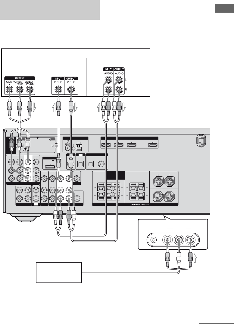
Getting Started
The following illustration shows how to
connect a component which has analog jacks
such as a DVD recorder, VCR, etc.
It is not necessary to connect all the cords.
Connect audio and video cords according to
the jacks of your components.
Connecting components with
analog video and audio jack
VIDEO L AUDIO R
AUTO CAL MIC VIDEO 2 IN
L
R
DIGITAL
(ASSIGNABLE)
DC5V
0.7A MAX
HDMIANTENNA
DMPORT
SIRIUS
SAT IN DVD IN BD IN OUT
AM
CENTER SURROUND
FRONT A
L
L
R
RLR
OUT IN
SA-CD
/
CD
/
CD-R
IN
TV
TV
AUDIO
IN
VIDEO
IN
SAT
AUDIO
OUT
VIDEO
OUT
IN
OPTICAL
MONITOR
AUDIO
IN
VIDEO
IN
BD
SPEAKERS
SURROUND BACK
/
BI-AMP
/
FRONT B
SAT
IN
DVD
IN
OPTICAL COAXIAL
EZW-T100
AUDIO
OUT
AUDIO
IN
Y
P
B
/
C
B
COMPONENT VIDEO
P
R
/
C
R
MONITOR
OUT
SAT
IN
DVD
IN
VIDEO 1
IN
SUBWOOFER
VIDEO 1
VIDEO
OUT
VIDEO
IN
DVD recorder, VCR
B
Audio signalsVideo signals
C
A
D
(On the front panel)
Camcorder/
video game
AComponent video cord (not supplied)
BVideo cord (not supplied)
CAudio cord (not supplied)
DAudio/video cord (not supplied)
continued
28US
Notes
• Be sure to change the factory setting of the
VIDEO 1 input button on the remote so that you
can use the button to control your DVD recorder.
For details, see “Changing button assignments”
(page 96).
• You can also rename the VIDEO 1 input so that it
can be displayed on the receiver’s display. For
details, see “Naming input” (page 37).
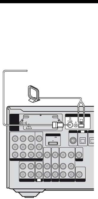
5: Connecting the
antennas (aerials)
Connect the supplied AM loop antenna
(aerial) and FM wire antenna (aerial).
Before connecting the antennas (aerials), be
sure to disconnect the AC power cord (mains
lead).
Notes
• To prevent noise pickup, keep the AM loop
antenna (aerial) away from the receiver and other
components.
• Be sure to fully extend the FM wire antenna
(aerial).
• After connecting the FM wire antenna (aerial),
keep it as horizontal as possible.
L
R
DIG
I
DC5V
0.7A MAX
DMPORT
SIRIUS
SAT
IN
AM
Y
P
B
/
C
B
COMPONENT VIDEO
OUT IN
P
R
/
C
R
DVD
IN
VIDEO 1
IN
MONITOR
OUT
SA-CD
/
CD
/
CD-R
VIDEO 1
IN
TV
TV
AUDIO
IN
VIDEO
IN
SAT
AUDIO
OUT
AUDIO
OUT
VIDEO
OUT
VIDEO
OUT
IN
OPTICAL
AUDIO
IN
VIDEO
IN
SUBWOOFER
MONITOR
AUDIO
IN
VIDEO
IN
BD
OPTIC
A
EZW-T100
ANTENNA
FM wire antenna (aerial) (supplied)
AM loop antenna (aerial)
(supplied)
29US
Getting Started
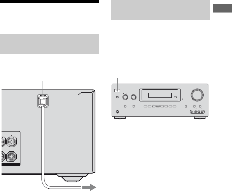
6: Preparing the receiver
and the remote
Connect the AC power cord (mains lead) to a
wall outlet.
Before using the receiver for the first time,
initialize the receiver by performing the
following procedure. This procedure can also
be used to return settings you have made to
their factory defaults.
Be sure to use the buttons on the receiver for
this operation.
1Press ?/1 to turn off the
receiver.
2Hold down ?/1 for 5 seconds.
“PUSH” and “ENTER” appears on the
display alternately.
3Press MEMORY/ENTER.
After “CLEARING” appears on the
display for a while, “CLEARED”
appears.
All the settings you have changed or
adjusted are reset to the initial settings.
Connecting the AC power cord
(mains lead)
FRONT A
AC power cord (mains lead)
To the wall outlet
Performing initial setup
operations
?/1
PHONES
SPEAKERS
INPUT SELECTOR
INPUT MODE TUNING MODE
MASTER VOLUME
TONE MODE DISPLAY DIMMER MUTING
MEMORY/
ENTER 2CH/
A.DIRECT A.F.D. MOVIE MUSICTUNING
TONE
VIDEO 2 IN
VIDEO L AUDIO RAUTO CAL MIC
?/1
MEMORY/ENTER
30US
Insert two R6 (size-AA) batteries in the
RM-AAU021 Remote Commander.
Observe the correct polarity when installing
batteries.
Notes
• Do not leave the remote in an extremely hot or
humid place.
• Do not use a new battery with old ones.
• Do not mix manganese batteries and other kinds of
batteries.
• Do not expose the remote sensor to direct sunlight
or lighting apparatuses. Doing so may cause a
malfunction.
• If you do not intend to use the remote for an
extended period of time, remove the batteries to
avoid possible damage from battery leakage and
corrosion.
• When you replace the batteries, the remote buttons
may be reset to their factory settings. If this
happens, reassign the buttons again (page 96).
• When the remote no longer operates the receiver,
replace all the batteries with new ones.
7: Selecting the speaker
system
You can select the front speakers you want to
drive.
Be sure to use the buttons on the receiver for
this operation.
Press SPEAKERS repeatedly to
select the front speaker system
you want to drive.
* To select “SP B”, set “SB ASGN” to “SPK B” in
the System settings menu (page 43).
To turn off the speaker output, press
SPEAKERS repeatedly until the “SP A” and
“SP B” indicators on the display light off.
Note
You cannot switch the front speaker system by
pressing SPEAKERS when the headphones are
connected to the receiver.
Inserting batteries into the
remote
To select Light up
The front speakers connected to the
SPEAKERS FRONT A terminals
SP A
The front speakers connected to the
SPEAKERS SURROUND BACK/
BI-AMP/FRONT B terminals
SP B*
The front speakers connected to both
the SPEAKERS FRONT A terminals
and SPEAKERS SURROUND
BACK/BI-AMP/FRONT B terminals
(parallel connection)
SP A and
SP B*
?/1
PHONES
SPEAKERS
INPUT SELECTOR
INPUT MODE TUNING MODE
MASTER VOLUME
TONE MODE DISPLAY DIMMER MUTING
MEMORY/
ENTER 2CH/
A.DIRECT A.F.D. MOVIE MUSICTUNING
TONE
VIDEO 2 IN
VIDEO L AUDIO RAUTO CAL MIC
SPEAKERS
31US
Getting Started
8: Calibrating the
appropriate settings
automatically
(AUTO CALIBRATION)
The DCAC (Digital Cinema Auto Calibration)
function allows you to perform automatic
calibration such as:
• Checking the connection between each
speaker and the receiver.
• Adjusting the speaker level.
• Measuring the distance of each speaker from
your listening position.
The DCAC is designed to obtain proper sound
balance in your room. However, you can
adjust the speaker levels and balance manually
according to your preference. For details, see
“9: Adjusting the speaker levels and balance
(TEST TONE)” (page 35).
Before you perform Auto Calibration, install
and connect the speakers (page 17, 18).
• The AUTO CAL MIC jack is used for the
supplied optimizer microphone only. Do not
connect other microphones to this jack.
Doing so may damage the receiver and the
microphone.
• During calibration, the sound that comes out
of the speakers is very loud. The volume of
the sound cannot be adjusted. Pay attention
to the presence of children or to the effect on
your neighborhood.
• Perform Auto Calibration in a quiet
environment to avoid the effect of noise and
to get a more accurate measurement.
• If there are any obstacles in the path between
the optimizer microphone and the speakers,
the calibration cannot be performed
correctly. Remove any obstacles from the
measurement area to avoid measurement
error.
• When you use a bi-amplifier connection, set
“SB ASGN” to “BI-AMP” in the System
settings menu before you perform auto
calibration (page 43).
Notes
• The Auto Calibration function does not work when
headphones are connected.
• If the muting function has been activated before
you perform Auto Calibration, the muting function
will be set to off automatically.
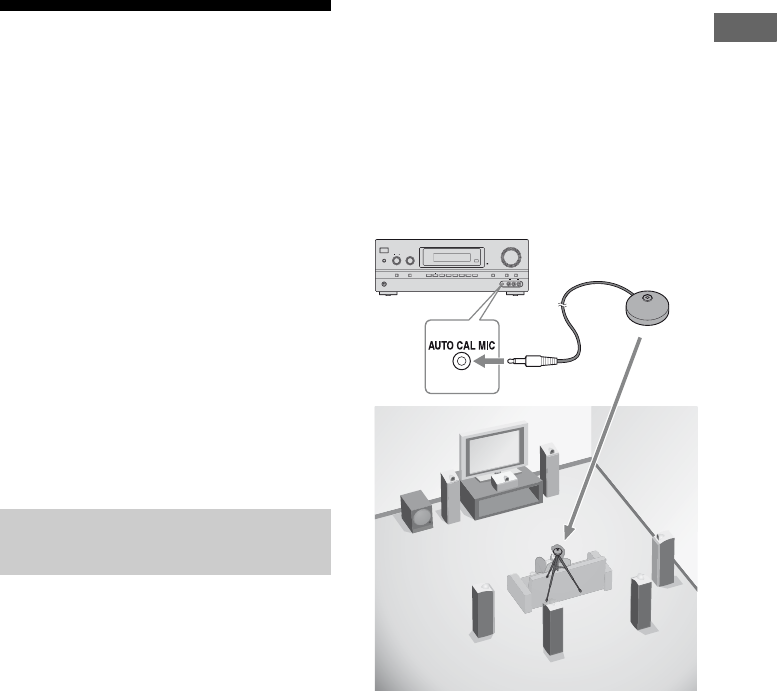
1Connect the supplied optimizer
microphone to the AUTO CAL
MIC jack.
2Set up the optimizer
microphone.
Place the optimizer microphone at your
listening position. You can also use a
stool or tripod so that the optimizer
microphone remains at the same height as
your ears.
Before you perform Auto
Calibration
?/1
PHONES
SPEAKERS
INPUT SELECTOR
INPUT MODE TUNING MODE
MASTER VOLUME
TONE MODE DISPLAY DIMMER MUTING
MEMORY/
ENTER 2CH/
A.DIRECT A.F.D. MOVIE MUSICTUNING
TONE
VIDEO 2 IN
VIDEO L AUDIO RAUTO CAL MIC
Optimizer microphone
32US
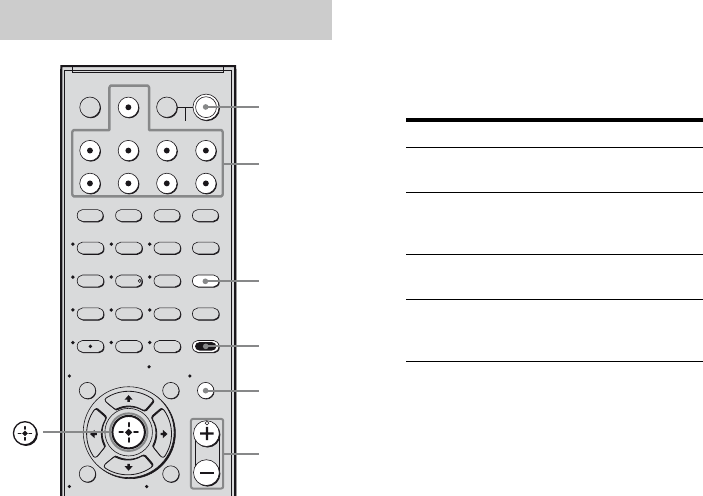
1Press AMP MENU.
2Press AUTO CAL.
Measurement starts in 5 seconds and the
display changes as follows:
A.CAL [5] t A.CAL [4] t A.CAL [3]
t A.CAL [2] t A.CAL [1]
While the time is counting down, stand
away from the measurement area to avoid
measurement error.
3Measurement starts.
The measurement process will take a few
minutes to complete.
The table below shows the display when
measurement starts.
* The corresponding speaker indicator lights
up in the display during measurement.
4Measurement ends.
“COMPLETE” appears on the display
and the settings are registered.
When you have finished
Disconnect the optimizer microphone from the
AUTO CAL MIC jack.
Notes
• Auto Calibration cannot detect the subwoofer.
Therefore, all subwoofer settings will be
maintained.
• If you have changed the position of the speakers, it
is recommended that you perform Auto Calibration
again in order to enjoy the surround sound.
Performing Auto Calibration
123
46
78
0/10
ENTER
9
SYSTEM STANDBY
TV INPUT
SLEEP DMPORT
VIDEO1 VIDEO2 BD DVD
2CH A.F.D. MOVIE MUSIC
AMP MENU
CLEAR
DISPLAY MUTING
TV VOL
MASTER VOL
DVD/BD
MENU
AUTO CAL
D.TUNING
D.SKIP
THEATER
SAT TV SA-CD/CD TUNER
?/1
5
>10
MEMORY
O
TV
?/1
AV
?/1
TOOLS/
OPTIONS
RETURN/EXIT
MENU/HOME
Input
buttons
?/1
switch
MUTING
MASTER
VOL +/–
AMP
MENU
AUTO
CAL
Measurement for Display
Environment noise
level
NOISE.CHK
Speaker connection MEASURE and SP
DET. appears
alternately*
Speaker level MEASURE and GAIN
appears alternately*
Speaker distance MEASURE and
DISTANCE appears
alternately*

33US
Getting Started
Tips
• When Auto Calibration starts:
– Stand some distance from the speakers and the
listening position to avoid measurement failure.
This is because test signals are output from the
speakers during measurement.
– Avoid making noise to get a more accurate
measurement.
• The Auto Calibration function will be canceled
when you do the following during the
measurement process:
– Press ?/1 or MUTING.
– Press the input buttons or turn the INPUT
SELECTOR on the receiver.
– Change the volume level.
– Connect the headphones.
– Press AUTO CAL again.
When error codes appear
When an error is detected during Auto
Calibration, an error code will appear on the
display cyclically after each measurement
process as follows:
Error code t blank display t (error code t
blank display)a) t PUSH t blank display
t ENTER
a) Appears when there are more than one error code.
To rectify the error
1Record down the error code.
2Press .
3Press ?/1 to turn off the receiver.
4Rectify the error.
For details, see “Error codes and remedies”
below.
5Turn on the receiver and perform Auto
Calibration again (page 32).
Error codes and remedies
When warning codes appear
During Auto Calibration, the warning code
provides information on the measurement
result. The warning code will appear on the
display cyclically as follows:
Warning code t blank display t (warning
code t blank display)b) t PUSH t blank
display t ENTER
b)Appears when there are more than one warning
code.
You can choose to ignore the warning code as
the Auto Calibration function will
automatically adjust the settings. You can also
change the settings manually.
Error and warning codes
Error code Cause and remedy
ERROR 10 The environment is too noisy.
Make sure the environment is quiet
during Auto Calibration.
ERROR 11 The speakers are placed too near
the optimizer microphone. Place
your speakers further away from
the optimizer microphone.
ERROR 12 None of the speakers are detected.
Make sure that the optimizer
microphone is connected properly
and perform Auto Calibration
again.
ERROR 20 Front speakers are not detected or
only one front speaker is detected.
Check the front speakers
connection.
ERROR 21 Only one surround speaker is
detected. Check the surround
speakers connection.
ERROR 22 The surround back speaker is
connected only to the SPEAKERS
SURROUND BACK/BI-AMP/
FRONT B R terminals. When you
connect only one surround back
speaker, connect it to the
SPEAKERS SURROUND BACK/
BI-AMP/FRONT B L terminals.
ERROR 23 Surround back speaker is detected
but surround speakers are not
connected. Be sure to connect the
surround speakers.
continued

34US
To change the settings
manually
1Record down the warning code.
2Press .
3Press ?/1 to turn off the receiver.
4Follow the solution provided in the
“Warning codes and solutions” below.
5Turn on the receiver and perform Auto
Calibration again (page 32).
Warning codes and solutions
c)For details, refer “Front speaker distance”
(page 53).
d)For details, refer “Tip” on page 54.
Warning
code
Explanation and solution
WARN. 40 The environment is noisy.
Make sure the environment is quiet
during Auto Calibration.
WARN. 60 The front speaker balance is out of
range. Reposition your front
speakers.c)
WARN. 62 The center speaker level is out of
range. Reposition your center
speaker.d)
WARN. 63 The surround left speaker level is
out of range. Reposition your
surround left speaker.d)
WARN. 64 The surround right speaker level is
out of range. Reposition your
surround right speaker.d)
WARN. 65 The surround back left speaker
level is out of range. Reposition
your surround back left speaker.d)
WARN. 66 The surround back right speaker
level is out of range. Reposition
your surround back right speaker.d)
WARN. 70 The front speaker distance is out of
range. Reposition your front
speakers.c)
WARN. 72 The center speaker distance is out
of range. Reposition your center
speaker.d)
WARN. 73 The surround left speaker distance
is out of range. Reposition your
surround left speaker.d)
WARN. 74 The surround right speaker distance
is out of range. Reposition your
surround right speaker.d)
Warning
code
Explanation and solution
WARN. 75 The surround back left speaker
distance is out of range. Reposition
your surround back left speaker.d)
WARN. 76 The surround back right speaker
distance is out of range. Reposition
your surround back right speaker.d)
35US
Getting Started
9: Adjusting the speaker
levels and balance
(TEST TONE)
You can adjust the speaker levels and balance
while listening to the test tone from your
listening position.
Tip
The receiver employs a test tone with a frequency
centered at 800 Hz.
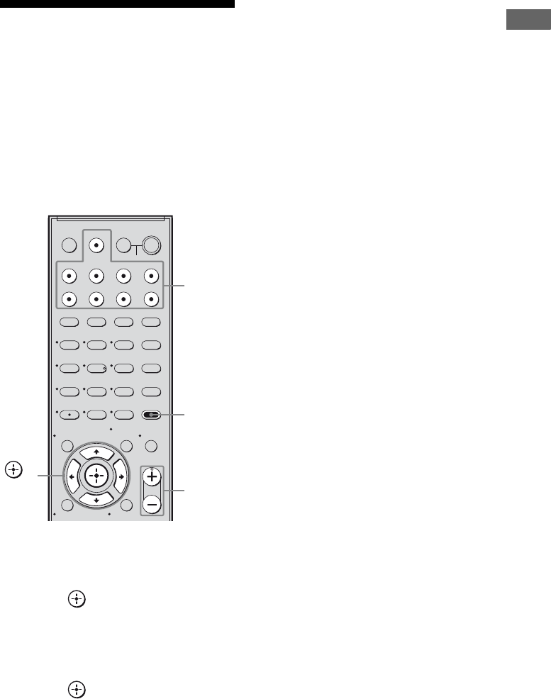
1Press AMP MENU.
“1-LEVEL” appears on the display.
2Press or b to enter the
menu.
3Press V/v repeatedly to select
“T. TONE”.
4Press or b to enter the
parameter.
5Press V/v repeatedly to select
“T. TONE Y”.
The test tone is output from each speaker
in sequence as follows:
Front left t Center t Front right t
Surround right t Surround back right*
t Surround back left* t Surround left
t Subwoofer
* You will only hear the test tone from the
– surround back left and right speakers when
surround back speakers are set to “DUAL”.
– surround back left speaker when surround
back speakers are set to “SINGLE”.
6Adjust the speaker levels and
balance using the LEVEL menu
so that the level of the test tone
sounds the same from each
speaker.
For details, see “Adjusting the level
(LEVEL menu)” (page 45).
Tips
• To adjust the level of all speakers at the same
time, press MASTER VOL +/–. You can also
use MASTER VOLUME on the receiver.
• The adjusted value is shown on the display
during adjustment.
7Repeat steps 1 to 5 to select
“T. TONE N”.
You can also press any input buttons.
The test tone turns off.
When a test tone is not output
from the speakers
• The speaker cords may not be connected
securely.
• The speaker cords may have the short-circuit
problem.
Note
The test tone does not work when ANALOG
DIRECT is selected.
123
46
78
0/10
ENTER
9
SYSTEM STANDBY
TV INPUT
SLEEP DMPORT
VIDEO1 VIDEO2 BD DVD
2CH A.F.D. MOVIE MUSIC
AMP MENU
CLEAR
DISPLAY MUTING
TV VOL
MASTER VOL
DVD/BD
MENU
AUTO CAL
D.TUNING
D.SKIP
THEATER
SAT TV SA-CD/CD TUNER
?/1
5
>10
MEMORY
O
TV
?/1
AV
?/1
TOOLS/
OPTIONS
RETURN/EXIT
MENU/HOME
AMP
MENU
MASTER
VOL +/–
Input
buttons
,
V/v/B/b
36US
Selecting a component
1Press the input button to select
a component.
You can also use INPUT SELECTOR on
the receiver.
The selected input appears on the display.
* “SA-CD/CD/CD-R” scrolls across the
display, then “SA-CD/CD” appears.
2Turn on the component and
start playback.
3Press MASTER VOL +/– to
adjust the volume.
You can also use MASTER VOLUME on
the receiver.
To activate the muting function
Press MUTING.
The muting function will be canceled when
you do the following.
• Press MUTING again.
• Increase the volume.
• Turn off the receiver.
To avoid damaging your
speakers
Before you turn off the receiver, be sure to turn
down the volume level.
Playback
Selected input
[Display]
Components that can
be played back
DMPORT
[DMPORT]
DIGITAL MEDIA PORT
adapter connected to the
DMPORT jack
VIDEO 1
[VIDEO 1]
DVD recorder, VCR, etc.,
connected to the VIDEO
1 jack
VIDEO 2
[VIDEO 2]
Camcorder, video game,
etc., connected to the
VIDEO 2 IN jack
BD
[BD]
Blu-ray disc player, etc.,
connected to the BD jack
DVD
[DVD]
DVD player, etc.,
connected to DVD jack
123
46
78
0/10
ENTER
9
SYSTEM STANDBY
TV INPUT
SLEEP DMPORT
VIDEO1 VIDEO2 BD DVD
2CH A.F.D. MOVIE MUSIC
AMP MENU
CLEAR
DISPLAY MUTING
TV VOL
MASTER VOL
DVD/BD
MENU
AUTO CAL
D.TUNING
D.SKIP
THEATER
SAT TV SA-CD/CD TUNER
?/1
5
>10
MEMORY
O
TV
?/1
AV
?/1
TOOLS/
OPTIONS
RETURN/EXIT
MENU/HOME
AMP
MENU
MASTER
VOL +/–
Input
buttons
,
V/v/B/b
MUTING
Selected input
[Display]
Components that can
be played back
SAT
[SAT]
Satellite tuner, etc.
connected to the SAT
jack
TV
[TV]
TV, etc. connected to the
TV jack
SA-CD/CD
[SA-CD/CD/
CD-R]*
Super Audio CD/CD
player/CD recorder, etc.,
connected to the SA-CD/
CD/CD-R jack
TUNER
[FM or AM band]
Built-in radio tuner
TUNER
[SIRIUS]
SiriusConnect Home
tuner connected to the
SIRIUS jack.

37US
Playback
You can enter a name of up to 8 characters for
inputs and display it on the receiver’s display.
This is convenient for labeling the jacks with
the names of the connected components.
1Press the input button to select
the input you want to create an
index name for.
You can also use INPUT SELECTOR on
the receiver.
2Press AMP MENU.
“1-LEVEL” appears on the display.
3Press V/v repeatedly to select
“7-SYSTEM”.
4Press or b to enter the
menu.
5Press V/v to select “NAME IN”.
6Press or b to enter the
parameter.
The cursor flashes and you can select a
character.
7Press V/v to select a character,
then press B/b to move the
cursor to the next position.
If you made a mistake
Press B/b until the character you want to
change flashes, then press V/v to select
the correct character.
Tips
• You can select the character type as follows
by pressing V/v.
Alphabet (upper case) t Numbers t
Symbols
• To enter a blank space, press b without
selecting a character.
8Press .
The name you entered is registered.
Naming input
38US
Listening/Watching a component
Listening to a Super Audio CD/CD
123
46
78
0/10
ENTER
9
SYSTEM STANDBY
TV INPUT
SLEEP DMPORT
VIDEO1 VIDEO2 BD DVD
2CH A.F.D.
TV CH –
PRESET –
TV CH +
PRESET +
TUNING –
TV
TUNING +
FM MODE
MOVIE MUSIC
AMP MENU
CLEAR
DISPLAY MUTING
TV VOL
MASTER VOL
DVD/BD
MENU
AUTO CAL
D.TUNING
D.SKIP
THEATER
SAT TV SA-CD/CD TUNER
?/1
.
HmM
Xx
<
<
>
5
>10
REPLAY ADVANCE
– CATEGORY +
CATEGORY MODE
MEMORY
O
TV
?/1
AV
?/1
TOOLS/
OPTIONS
RETURN/EXIT
MENU/HOME
?/1
PHONES
SPEAKERS
INPUT SELECTOR
INPUT MODE TUNING MODE
MASTER VOLUME
TONE MODE DISPLAY DIMMER MUTING
MEMORY/
ENTER 2CH/
A.DIRECT A.F.D. MOVIE MUSICTUNING
TONE
VIDEO 2 IN
VIDEO L AUDIO RAUTO CAL MIC
5
5
3
2
3
Notes
• The operation is described for a
Sony Super Audio CD player.
• Refer to the operating
instructions supplied with the
Super Audio CD player or CD
player.
Tip
You can select the sound field to
suit the music. Refer to page 58
for details.
Recommended sound fields:
Classical: HALL
Jazz: JAZZ
Live concert: CONCERT
1Turn on the Super Audio CD player/CD
player, then place the disc on the tray.
2Turn on the receiver.
3Press SA-CD/CD.
You can also use INPUT SELECTOR on the receiver to
select “SA-CD/CD/CD-R”.
4Play back the disc.
5Adjust to a suitable volume.
6After you have finished listening to the
Super Audio CD/CD, eject the disc and turn
off the receiver and Super Audio CD player/
CD player.
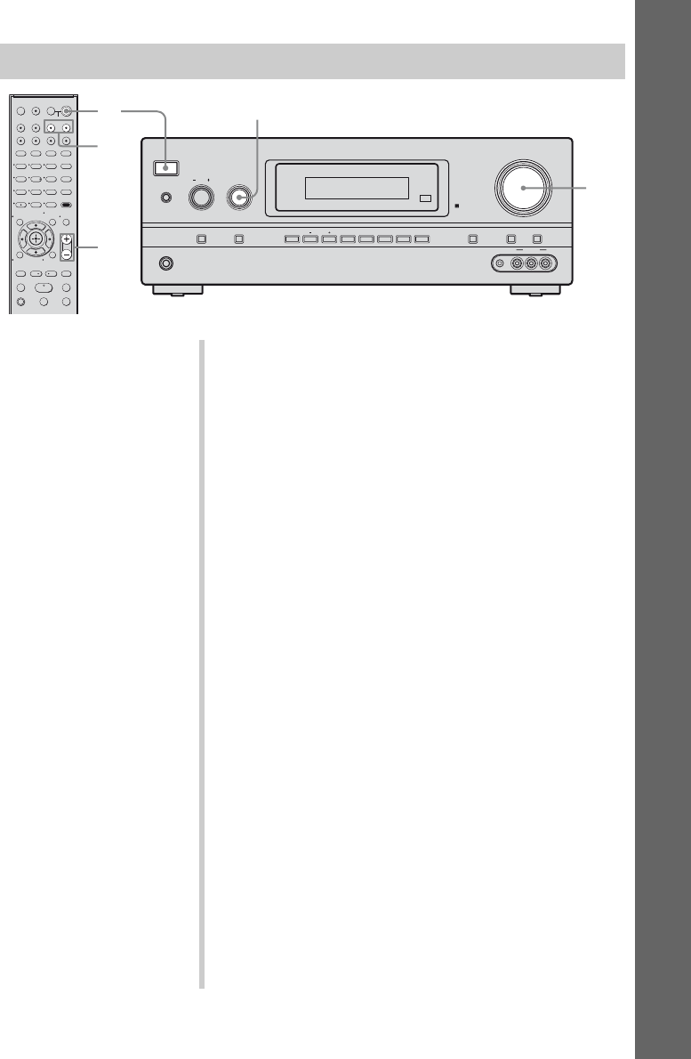
39US
Playback
Watching a DVD/Blu-ray disc
123
46
78
0/10
ENTER
9
SYSTEM STANDBY
TV INPUT
SLEEP DMPORT
VIDEO1 VIDEO2 BD DVD
2CH A.F.D.
TV CH –
PRESET –
TV CH +
PRESET +
TUNING –
TV
TUNING +
FM MODE
MOVIE MUSIC
AMP MENU
CLEAR
DISPLAY MUTING
TV VOL
MASTER VOL
DVD/BD
MENU
AUTO CAL
D.TUNING
D.SKIP
THEATER
SAT TV SA-CD/CD TUNER
?/1
.
HmM
Xx
<
<
>
5
>10
REPLAY ADVANCE
– CATEGORY +
CATEGORY MODE
MEMORY
O
TV
?/1
AV
?/1
TOOLS/
OPTIONS
RETURN/EXIT
MENU/HOME
?/1
PHONES
SPEAKERS
INPUT SELECTOR
INPUT MODE TUNING MODE
MASTER VOLUME
TONE MODE DISPLAY DIMMER MUTING
MEMORY/
ENTER 2CH/
A.DIRECT A.F.D. MOVIE MUSICTUNING
TONE
VIDEO 2 IN
VIDEO L AUDIO RAUTO CAL MIC
2
3
6
6
3
Notes
• Refer to the operating
instructions supplied with the
TV and DVD player/Blu-ray
disc player.
• Check the following if you
cannot listen to multi channel
sound.
– Be sure this receiver is
connected to the DVD player/
Blu-ray disc player via a
digital connection.
– Be sure the digital audio
output of the DVD player/
Blu-ray disc player is set up
properly.
Tips
• Select the sound format of the
disc to be played, if necessary.
• You can select the sound field to
suit the movie/music. Refer to
page 58 for details.
Recommended sound fields:
Movie: C.ST.EX
Music: CONCERT
1Turn on the TV and DVD player/Blu-ray disc
player.
2Turn on the receiver.
3Press DVD to watch a DVD or press BD to
watch a Blu-ray disc.
You can also use INPUT SELECTOR on this receiver to
select “DVD” or “BD”.
4Switch the input of the TV so that an image
of the DVD/Blu-ray disc is displayed.
5Play back the disc.
6Adjust to a suitable volume.
7After you have finished watching the DVD/
Blu-ray disc, eject the disc and turn off the
receiver, TV and DVD player/Blu-ray disc
player.
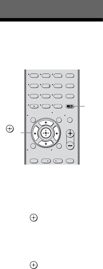
40US
Navigating through
menus
By using the amplifier menus, you can make
various adjustments to customize the receiver.
1Press AMP MENU.
“1-LEVEL” appears on the display.
2Press V/v repeatedly to select
the menu you want.
3Press or b to enter the
menu.
4Press V/v repeatedly to select
the parameter you want to
adjust.
5Press or b to enter the
parameter.
6Press V/v repeatedly to select
the setting you want.
The setting is entered automatically.
To return to the previous
display
Press B.
To exit the menu
Press AMP MENU.
Note
Some parameters and settings may appear dimmed
on the display. This means that they are either
unavailable or fixed and unchangeable.
Amplifier Operations
123
46
78
0/10
ENTER
9
TV CH –
PRESET –
TV CH +
PRESET +
AMP MENU
CLEAR
DISPLAY MUTING
TV VOL
MASTER VOL
DVD/BD
MENU
AUTO CAL
D.TUNING
D.SKIP
THEATER
.<
<
>
5
>10
REPLAY ADVANCE
– CATEGORY +
MEMORY
O
TOOLS/
OPTIONS
RETURN/EXIT
MENU/HOME
AMP
MENU
,
V/v/B/b

41US
Amplifier Operations
The following options are available in each
menu. For details on navigating through
menus, see page 40.
Overview of the menus
Menu
[Display]
Parameters
[Display]
Settings Initial
setting
LEVEL
[1-LEVEL]
(page 45)
Test tonea) [T. TONE] T. TONE N, T. TONE Y T. TONE N
Front speaker balancea)
[FRT BAL]
BAL. L +1 to BAL. L +8, BALANCE,
BAL. R +1 to BAL. R +8
BALANCE
Center speaker level
[CNT LVL]
CNT –10 dB to CNT +10 dB
(1 dB step)
CNT 0 dB
Surround left speaker level
[SL LVL]
SUR L –10 dB to SUR L +10 dB
(1 dB step)
SUR L 0 dB
Surround right speaker level
[SR LVL]
SUR R –10 dB to SUR R +10 dB
(1 dB step)
SUR R 0 dB
Surround back speaker levelb)
[SB LVL]
SB –10 dB to SB +10 dB
(1 dB step)
SB 0 dB
Surround back left speaker
levelc) [SBL LVL]
SBL –10 dB to SBL +10 dB
(1 dB step)
SBL 0 dB
Surround back right speaker
levelc) [SBR LVL]
SBR –10 dB to SBR +10 dB
(1 dB step)
SBR 0 dB
Subwoofer level
[SW LVL]
SW –10 dB to SW +10 dB
(1 dB step)
SW 0 dB
Dynamic range compressora)
[D. RANGE]
COMP. OFF, COMP. STD,
COMP. MAX
COMP. OFF
EQ
[2-EQ]
(page 46)
Equalizer on/offa) [EQ] EQ OFF, EQ ON EQ OFF
Front speaker bass levela)
[BASS LVL]
BASS –6 dB to BASS +6 dB
(1 dB step)
BASS 0 dB
Front speaker treble levela)
[TRE LVL]
TRE –6 dB to TRE +6 dB
(1 dB step)
TRE 0 dB
SUR
[3-SUR]
(page 46)
Sound field selectiona)
[S.F. SELCT]
For details, see “Enjoying Surround
Sound” (page 56).
A.F.D. AUTO
Surround back decoding
modea) [SB DEC]
SB OFF, SB AUTO, SB ON SB AUTO
Effect levela) [EFFECT] EFCT. MIN, EFCT. STD,
EFCT. MAX
EFCT. STD
continued

42US
Menu
[Display]
Parameters
[Display]
Settings Initial
setting
TUNER
[4-TUNER]
(page 48)
FM station receiving modea)
[FM MODE]
FM AUTO, FM MONO FM AUTO
Naming preset stationsa)
[NAME IN]
For details, see “Naming preset
stations” (page 65).
Parental locka)d)
[PARENTAL]
OFF, ON OFF
Lock code edita)d)
[CODE EDT.]
For details, see “Restricting access to
specific channels (Parental Lock)
(SIRIUS only)” (page 72).
SIRIUS antenna aiming
modea)d)
[SR ANT]
For details, see “Checking receiving
conditions (SIRIUS Antenna Aiming)”
(page 68).
SIRIUS radio IDa)d)
[SR ID]
For details, see “Checking the SIRIUS
Radio ID” (page 67).
AUDIO
[5-AUDIO]
(page 49)
Digital audio input decoding
prioritya) [DEC. PRI.]
DEC. PCM, DEC. AUTO DEC. PCM for:
SA-CD/CD;
DEC. AUTO
for:
VIDEO 1, 2,
BD, DVD,
SAT, TV
Digital broadcast language
selectiona) [DUAL]
DUAL M/S, DUAL M, DUAL S,
DUAL M+S
DUAL M
Synchronizes audio with video
outputa) [A.V. SYNC.]
A.V.SYNC. N, A.V.SYNC. Y A.V.SYNC. N
Digital audio input assignmenta)
[D. ASSIGN]
For details, see “Listening to digital
sound from other inputs (DIGITAL
ASSIGN)” (page 89).
HDMI
[6-HDMI]
(page 50)
Audio for HDMIa)e)
[AUDIO FOR HDMI]
AMP, TV+AMP AMP
Control for HDMIa)e)
[CONTROL FOR HDMI]
CTRL OFF, CTRL ON CTRL OFF

43US
Amplifier Operations
Menu
[Display]
Parameters
[Display]
Settings Initial
setting
SYSTEM
[7-SYSTEM]
(page 51)
Subwoofera)
[SW SPK]
NO, YES YES
Front speakersa)
[FRT SPK]
SMALL, LARGE LARGE
Center speakera)
[CNT SPK]
NO, SMALL, LARGE LARGE
Surround speakersa)
[SUR SPK]
NO, SMALL, LARGE LARGE
Surround back speakersa)
[SB SPK]
NO, SINGLE, DUAL DUAL
Surround back speaker assigna)f)
[SB ASGN]
OFF, BI-AMP, SPK B OFF
Front speaker distancea)
[FRT DIST.]
DIST. 3 ft. to DIST. 23 ft.
(1 ft. step)
DIST. 10 ft.
Center speaker distancea)
[CNT DIST.]
DIST. 3 ft. to DIST. 23 ft.
(1 ft. step)
DIST. 10 ft.
Surround left speaker distancea)
[SL DIST.]
DIST. 3 ft. to DIST. 23 ft.
(1 ft. step)
DIST. 10 ft.
Surround right speaker distancea)
[SR DIST.]
DIST. 3 ft. to DIST. 23 ft.
(1 ft. step)
DIST. 10 ft.
Surround back speaker
distancea)b)
[SB DIST.]
DIST. 3 ft. to DIST. 23 ft.
(1 ft. step)
DIST. 10 ft.
Surround back left speaker
distancea)c)
[SBL DIST.]
DIST. 3 ft. to DIST. 23 ft.
(1 ft. step)
DIST. 10 ft.
Surround back right speaker
distancea)c)
[SBR DIST.]
DIST. 3 ft. to DIST. 23 ft.
(1 ft. step)
DIST. 10 ft.
Surround speaker positiona)
[SUR POS.]
BEHD/HI, BEHD/LO, SIDE/HI,
SIDE/LO
SIDE/LO
Speaker crossover frequencya)
[CRS. FREQ]
CRS > 40 Hz to CRS > 160 Hz
(10 Hz step)
CRS > 100 Hz
Brightness of the displaya)
[DIMMER]
0% dim, 40% dim, 70% dim 0% dim
Naming inputsa)
[NAME IN]
For details, see “Naming input”
(page 37).
A. CAL
[8-A. CAL]
(page 55)
Auto Calibrationa)
[AUTO CAL]
A.CAL NO, A.CAL YES A.CAL NO
continued

44US
a)For details, refer to the page in the parentheses.
b)You can only select this parameter when the surround back speakers are set to “SINGLE”.
c)You can only select this parameter when the surround back speakers are set to “DUAL”.
d)This parameter is only available if the SiriusConnect Home tuner is connected to the SIRIUS jack on the
receiver.
e)“AUDIO FOR HDMI” and “CONTROL FOR HDMI” scroll across the display, then “AUDIO” and
“CONTROL” appear respectively.
f) You can only select this parameter when the surround back speakers are set to “NO”.
g)This parameter is only available if the S-AIR transmitter (not supplied) is inserted to the EZW-T100 slot on
the receiver.
Menu
[Display]
Parameters
[Display]
Settings Initial
setting
S-AIR
[9- S-AIR]
(page 56)
S-AIR IDg)
[ID SETUP]
ID A, ID B, ID C ID A
Pairingg)
[PAIRING]
START, STATUS
S-AIR Modeg)
[MODE]
PARTY, SEPARATE PARTY
RF Changeg)
[RF SETUP]
RF AUTO, RF ON, RF OFF RF AUTO
S-AIR Standbyg)
[STANDBY]
STBY ON, STBY OFF STBY OFF

45US
Amplifier Operations
Adjusting the level
(LEVEL menu)
You can use the LEVEL menu to adjust the
balance and level of each speaker. These
settings are applied to all sound fields.
Select “1-LEVEL” in the amplifier menus. For
details on adjusting the parameters, see
“Navigating through menus” (page 40) and
“Overview of the menus” (page 41).
LEVEL menu parameters
xT. TONE (Test tone)
Lets you adjust the speaker levels and balance
while listening to the test tone from your
listening position. For details, see
“9: Adjusting the speaker levels and balance
(TEST TONE)” (page 35).
xFRT BAL (Front speaker
balance)
Lets you adjust the balance between front left
and right speakers.
xCNT LVL (Center speaker level)
xSL LVL (Surround left speaker
level)
xSR LVL (Surround right speaker
level)
xSB LVL (Surround back speaker
level)a)
xSBL LVL (Surround back left
speaker level)b)
xSBR LVL (Surround back right
speaker level)b)
xSW LVL (Subwoofer level)
a)You can only select this parameter when the
surround back speakers are set to “SINGLE” in
SYSTEM menu.
b)You can only select this parameter when the
surround back speakers are set to “DUAL” in
SYSTEM menu.
xD. RANGE (Dynamic range
compressor)
Lets you compress the dynamic range of the
sound track. This may be useful when you
want to watch movies at low volumes late at
night. Dynamic range compression is possible
with Dolby Digital sources only.
• COMP. OFF
The dynamic range is not compressed.
•COMP. STD
The dynamic range is compressed as
intended by the recording engineer.
•COMP. MAX
The dynamic range is compressed
dramatically.
Tip
Dynamic range compressor lets you compress the
dynamic range of the soundtrack based on the
dynamic range information included in the Dolby
Digital signal.
“COMP. STD” is the standard setting, but it only
enacts light compression. Therefore, we recommend
using the “COMP. MAX” setting. This greatly
compresses the dynamic range and lets you view
movies late at night at low volumes. Unlike analog
limiters, the levels are predetermined and provide a
very natural compression.

46US
Adjusting the equalizer
(EQ menu)
You can use the EQ menu to adjust the tonal
quality (bass/treble level) of the front
speakers.
Select “2-EQ” in the amplifier menus. For
details on adjusting the parameters, see
“Navigating through menus” (page 40) and
“Overview of the menus” (page 41).
EQ menu parameters
xEQ (Equalizer on/off)
Lets you turn the equalizer on or off.
•EQ OFF
The equalizer is turned off.
•EQ ON
The equalizer is turned on.
xBASS LVL (Front speaker bass
level)
xTRE LVL (Front speaker treble
level)
Notes
• This function does not work for signals with a
sampling frequency of more than 48 kHz.
• If you adjust the equalizer during DTS 96/24 signal
reception, the signal will be output only at 48 kHz.
Settings for the surround
sound
(SUR menu)
You can use the SUR menu to select the sound
field you want for your listening pleasure.
Select “3-SUR” in the amplifier menus. For
details on adjusting the parameters, see
“Navigating through menus” (page 40) and
“Overview of the menus” (page 41).
SUR menu parameters
xS.F. SELCT (Sound field
selection)
Lets you select the sound field you want. For
details, see “Enjoying Surround Sound” (page
56).
Note
The receiver lets you apply the last selected sound
field to an input whenever it is selected (Sound Field
Link). For example, if you select “HALL” for the
DVD input, then change to a different input and then
return to DVD, “HALL” will automatically be
applied again.
xSB DEC (Surround back
decoding mode)
Lets you select the surround back decoding
mode. For details, see “Using the surround
back decoding mode (SB DEC)” (page 47).
xEFFECT (Effect level)
Lets you adjust the “presence” of the surround
effect for sound fields selected with the
MOVIE or MUSIC buttons.
•EFCT. MIN
The surround effect is minimum.
• EFCT. STD
The surround effect is standard.
•EFCT. MAX
The surround effect is maximum.
47US
Amplifier Operations
By decoding the surround back signal of DVD
software (etc.) recorded in Dolby Digital
Surround EX, DTS-ES Matrix, DTS-ES
Discrete 6.1, etc., format, you can enjoy the
surround sound intended by the filmmakers.
Select the surround back decoding mode using
“SB DEC” on the SUR menu (page 46).
Types of the surround back
decoding functions
xSB OFF
Surround back decoding is not performed.
xSB AUTO
When the input stream contains the 6.1
channel decode flaga), the appropriate
decoding is performed on the surround back
signal.
xSB ON
To decode the surround back signal regardless
of the 6.1 channel decode flaga), Dolby Digital
EX is applied when the output channel is 6.1.
a)A 6.1 channel decode flag is information recorded
in software such as DVDs.
b)A Dolby Digital DVD that includes a Surround EX
flag. The Dolby Corporation web page can help
you distinguish Surround EX films.
c)Software encoded with a flag to denote it has both
DTS-ES Matrix and 5.1 channel signals.
d)Software encoded with both 5.1 channel signals
and an extension stream designed for returning
those signals to 6.1 discrete channels. Discrete 6.1
channel signals are DVD specific signals not used
in movie theaters.
e)When two surround back speakers are connected,
the output channel will be 7.1 channel.
Using the surround back
decoding mode (SB DEC)
Input stream Output
channel
Surround back
decoding
Dolby Digital
5.1
5.1e) —
Dolby Digital
Surround EXb) 6.1e) Matrix decoder that
conforms to Dolby
Digital EX
DTS 5.1 5.1e) —
DTS-ES
Matrix 6.1c) 6.1e) DTS Matrix decoding
DTS-ES
Discrete 6.1d) 6.1e) DTS Discrete
decoding
Dolby Digital
Surround EXb) 7.1 Matrix decoder that
conforms to Dolby
Pro Logic IIx
DTS-ES Matrix
6.1c) 7.1 DTS Matrix decoding
DTS-ES
Discrete 6.1d) 7.1 DTS Discrete
decoding
Input stream Output
channel
Surround back
decoding
Dolby Digital
5.1
6.1e) Matrix decoder that
conforms to Dolby
Digital EX
Dolby Digital
Surround EXb) 6.1e) Matrix decoder that
conforms to Dolby
Digital EX
DTS 5.1 6.1e) Matrix decoder that
conforms to Dolby
Digital EX
DTS-ES
Matrix 6.1c) 6.1e) Matrix decoder that
conforms to Dolby
Digital EX
DTS-ES
Discrete 6.1d) 6.1e) Matrix decoder that
conforms to Dolby
Digital EX
Dolby Digital
5.1
7.1 Matrix decoder that
conforms to Dolby
Pro Logic IIx
Dolby Digital
Surround EXb) 7.1 Matrix decoder that
conforms to Dolby
Pro Logic IIx
DTS 5.1 7.1 Matrix decoder that
conforms to Dolby
Digital EX
DTS-ES
Matrix 6.1c) 7.1 Matrix decoder that
conforms to Dolby
Digital EX
DTS-ES
Discrete 6.1d) 7.1 Matrix decoder that
conforms to Dolby
Digital EX
continued

48US
Notes
• There may be no sound from the surround back
speaker in Dolby Digital EX mode. Some discs
have no Dolby Digital Surround EX flag even
though the packages have Dolby Digital EX logos.
In this case, select “SB ON”.
• You can select the surround back decoding mode
only when A.F.D. mode is selected. However, this
function is canceled when Dolby Pro Logic IIx is
selected.
Settings for the tuner
(TUNER menu)
You can use the TUNER menu to set the FM
station receiving mode and to name preset
stations.
Select “4-TUNER” in the amplifier menus.
For details on adjusting the parameters, see
“Navigating through menus” (page 40) and
“Overview of the menus” (page 41).
TUNER menu parameters
xFM MODE (FM station receiving
mode)
•FM AUTO
This receiver will decode the signal as stereo
signal when the radio station is broadcast in
stereo.
• FM MONO
This receiver will decode the signal as mono
signal regardless of the broadcast signal.
xNAME IN (Naming preset
stations)
Lets you set the name of preset stations. For
details, see “Naming preset stations” (page
65).
xPARENTAL (Parental lock)
Lets you restrict access to certain channels
using your own lock code. For details, see
“Restricting access to specific channels
(Parental Lock) (SIRIUS only)” (page 72).
xCODE EDT. (Lock code edit)
Lets you change the lock code. For details, see
“To change the lock code (Lock Code)” (page
72).
xSR ANT (SIRIUS antenna aiming
mode)
This parameter helps you to aim the SIRIUS
antenna for optimal signal reception. For
details, see “Checking receiving conditions
(SIRIUS Antenna Aiming)” (page 68).

49US
Amplifier Operations
xSR ID (SIRIUS radio ID)
Lets you check the SIRIUS Radio ID. For
details, see “Checking the SIRIUS Radio ID”
(page 67).
Settings for the audio
(AUDIO menu)
You can use the AUDIO menu to make
settings for the audio to suit your preference.
Select “5-AUDIO” in the amplifier menus. For
details on adjusting the parameters, see
“Navigating through menus” (page 40) and
“Overview of the menus” (page 41).
AUDIO menu parameters
xDEC. PRI. (Digital audio input
decoding priority)
Lets you specify the input mode for the digital
signal input to the DIGITAL IN and HDMI IN
jacks.
•DEC. PCM
When signals from the DIGITAL IN jack are
selected, PCM signals are given priority (to
prevent interruption when playback starts).
However, when other signals are input, there
may be no sound, depending on the format.
In this case, set this item to “DEC. AUTO”.
When signals from the HDMI IN jack are
selected, only PCM signals are output from
the connected player. When signals in any
other format are received, set this item to
“DEC. AUTO”.
•DEC. AUTO
Automatically switches the input mode
between DTS, Dolby Digital, or PCM.
Note
When set to “DEC. AUTO” and the sound from the
digital audio jacks (for a CD, etc.) is interrupted
when playback starts, set to “DEC. PCM”.
continued

50US
xDUAL (Digital broadcast
language selection)
Lets you select the language you want to listen
to during digital broadcast. This feature only
functions for Dolby Digital sources.
• DUAL M/S (Main/Sub)
Sound of the main language will be output
through the front left speaker and sound of
the sub language will be output through the
front right speaker simultaneously.
•DUAL M (Main)
Sound of the main language will be output.
• DUAL S (Sub)
Sound of the sub language will be output.
•DUAL M+S (Main + Sub)
Mixed sound of both the main and sub
languages will be output.
xA.V. SYNC. (Synchronizes audio
with video output)
• A.V.SYNC. N (No) (Delay time: 0 ms)
The audio output is not delayed.
• A.V.SYNC. Y (Yes) (Delay time: 60 ms)
The audio output is delayed so that the time
gap between the audio output and visual
display is minimized.
Notes
• This parameter is useful when you use a large LCD
or plasma TV or a projector.
• This parameter is valid only when you use a sound
field selected with the 2CH or A.F.D. buttons.
• This parameter is not valid when
– signals with a sampling frequency of more than
48 kHz is input.
– the multi channel Linear PCM signals are
received via an HDMI IN jack.
– ANALOG DIRECT function is selected.
xD. ASSIGN
(Digital audio input assignment)
Lets you assign the digital audio input to other
input source. For details, see “Listening to
digital sound from other inputs (DIGITAL
ASSIGN)” (page 89).
Settings for the HDMI
(HDMI menu)
You can use the HDMI menu to make various
adjustments for HDMI.
Select “6-HDMI” in the amplifier menus. For
details on adjusting the parameters, see
“Navigating through menus” (page 40) and
“Overview of the menus” (page 41).
HDMI menu parameters
xAUDIO FOR HDMI (Audio for
HDMI)
Lets you set the audio output for HDMI from
the playback component connected to the
receiver via an HDMI connection.
•AMP
The HDMI audio signals from the playback
component is only output to speakers
connected to the receiver. Multi-channel
sound can be played back as it is.
Note
Audio signals are not output from the TV’s
speakers when “AUDIO FOR HDMI” is set to
“AMP”.
• TV+AMP
The sound is output from TV’s speaker and
the speakers connected to the receiver.
Notes
• The sound quality of the playback component
depends on the TV’s sound quality, such as the
number of channels, and the sampling
frequency, etc. When the TV has stereo
speakers, the sound output from the receiver is
also stereo as that of the TV, even if you play
back multi-channel source.
• When you connect the receiver to a video
component (projector, etc.), sound may not be
output from the receiver. In this case, select
“AMP”.

51US
Amplifier Operations
xCONTROL FOR HDMI (Control
for HDMI)
Lets you turn the Control for HDMI function
on or off. For details, see ““BRAVIA” Sync
Features” (page 75).
Settings for the system
(SYSTEM menu)
You can use the SYSTEM menu to set the size
and distance of the speakers connected to this
system.
Select “7-SYSTEM” in the amplifier menus.
For details on adjusting the parameters, see
“Navigating through menus” (page 40) and
“Overview of the menus” (page 41).
SYSTEM menu parameters
xSW SPK (Subwoofer)
•NO
If you have not connected a subwoofer,
select “NO”. This activates the bass
redirection circuitry and outputs the LFE
signals from other speakers.
•YES
If you have connected a subwoofer, select
“YES”.
Tip
In order to take full advantage of the Dolby Digital
bass redirection circuitry, we recommend setting the
subwoofer’s cut off frequency as high as possible.
xFRT SPK (Front speakers)
•SMALL
If the sound is distorted, or you feel a lack of
surround effects when using multi channel
surround sound, select “SMALL” to activate
the bass redirection circuitry and output the
front channel bass frequencies from the
subwoofer. When the front speakers are set
to “SMALL”, the center and surround
speakers are also automatically set to
“SMALL” (unless previously set to “NO”).
• LARGE
If you connect large speakers that will
effectively reproduce bass frequencies,
select “LARGE”. Normally, select
“LARGE”. When the subwoofer is set to
“NO”, the front speakers are automatically
set to “LARGE”.
continued
52US
xCNT SPK (Center speaker)
• NO
If you have not connected a center speaker,
select “NO”. The sound of the center
channel will be output from the front
speakers.
•SMALL
If the sound is distorted, or you feel a lack of
surround effects when using multi channel
surround sound, select “SMALL” to activate
the bass redirection circuitry and output the
center channel bass frequencies from the
front speakers (if set to “LARGE”) or
subwoofer.
• LARGE
If you connect a large speaker that will
effectively reproduce bass frequencies,
select “LARGE”. Normally, select
“LARGE”. However, if the front speakers
are set to “SMALL”, you cannot set the
center speaker to “LARGE”.
xSUR SPK (Surround speakers)
The surround back speakers will be set to the
same setting.
•NO
If you have not connected surround
speakers, select “NO”.
•SMALL
If the sound is distorted, or you feel a lack of
surround effects when using multi channel
surround sound, select “SMALL” to activate
the bass redirection circuitry and output the
surround channel bass frequencies from the
subwoofer or other “LARGE” speakers.
• LARGE
If you connect large speakers that will
effectively reproduce bass frequencies,
select “LARGE”. Normally, select
“LARGE”. However, if the front speakers
are set to “SMALL”, you cannot set the
surround speakers to “LARGE”.
xSB SPK (Surround back
speakers)
When the surround speakers are set to “NO”,
the surround back speakers are also
automatically set to “NO” and the setting
cannot be changed.
•NO
If you have not connected a surround back
speaker, select “NO”.
• SINGLE
If you connect only one surround back
speaker, select “SINGLE”. The sound will
be output to a maximum of 6.1 channel.
•DUAL
If you connect two surround back speakers,
select “DUAL”. The sound will be output to
a maximum of 7.1 channel.
Tip
The “LARGE” and “SMALL” settings for each
speaker determine whether the internal sound
processor will cut the bass signal from that channel.
When the bass is cut from a channel, the bass
redirection circuitry sends the corresponding bass
frequencies to the subwoofer or other “LARGE”
speakers.
However, since bass sounds have a certain amount
of directionality, it is best not to cut them, if
possible. Therefore, even when using small
speakers, you can set them to “LARGE” if you want
to output the bass frequencies from that speaker. On
the other hand, if you are using a large speaker, but
prefer not to have bass frequencies output from that
speaker, set it to “SMALL”.
If the overall sound level is lower than you prefer,
set all speakers to “LARGE”. If there is not enough
bass, you can use the equalizer to boost the bass
levels. For details, see page 41.
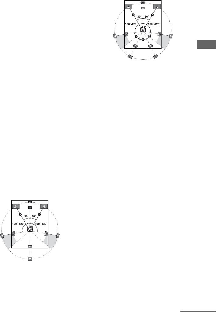
53US
Amplifier Operations
xSB ASGN (Surround back
speaker assign)
•OFF
If you connect surround back speakers to the
SPEAKERS SURROUND BACK/BI-AMP/
FRONT B terminals, select “OFF”.
•BI-AMP
If you connect front speakers to the
SPEAKERS SURROUND BACK/BI-AMP/
FRONT B terminals using a bi-amplifier
connection, select “BI-AMP”.
•SPK B
If you connect an additional front speaker
system to the SPEAKERS SURROUND
BACK/BI-AMP/FRONT B terminals, select
“SPK B”.
Notes
• SB ASGN cannot be selected if SB SPK is set to
“SINGLE” or “DUAL”.
• SB ASGN will be set to “OFF” automatically if
you set SB SPK to “SINGLE” or “DUAL”.
xFRT DIST. (Front speaker
distance)
Lets you set the distance from your listening
position to the front speakers (A).
If both front speakers are not placed an equal
distance from your listening position, set the
distance to the closest speaker.
With only one surround back
speaker
With two surround back speakers
(The angle B should be the same)
xCNT DIST. (Center speaker
distance)
Lets you set the distance from your listening
position to the center speaker.
xSL DIST. (Surround left speaker
distance)
xSR DIST. (Surround right
speaker distance)
Lets you set the distance from your listening
position to the surround speakers.
xSB DIST. (Surround back
speaker distance)a)
xSBL DIST. (Surround back left
speaker distance)b)
xSBR DIST. (Surround back right
speaker distance)b)
Lets you set the distance from your listening
position to the surround back speakers.
a)You can only select this parameter when the
surround back speakers are set to “SINGLE” in
SYSTEM menu.
b)You can only select this parameter when the
surround back speakers are set to “DUAL” in
SYSTEM menu.
continued
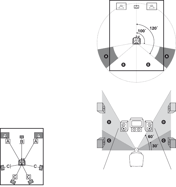
54US
Tip
To enjoy better surround sound, the distance
between the center speaker and the listening position
B cannot be more than 5 feet closer than the one
between the listening position and the front speaker
A. Place the speakers so that the difference in the
length of B in the following diagram is no more
than 5 feet closer than the length of A.
Example: Adjust the distance B to 15 feet or more
when the distance A is 20 feet.
Also, the distance between the surround speakers/
surround back speakers and the listening position
C cannot be more than 15 feet closer than the
distance between the listening position and the front
speakers A. Place the speakers so that the
difference in the length of C in the following
diagram is no more than 15 feet closer than the
length of A.
Example: Adjust the distance C to 5 feet or more
when the distance A is 20 feet.
This is important because incorrect speaker
placement is not conductive to the enjoyment of
surround sound. Please note that placing the
speakers closer than the required will cause a delay
in the output of the sound from that speaker. In other
words, the speaker will sound like it is farther away.
Adjusting these parameter while listening to the
sound often results in much better surround sound.
Give it a try!
xSUR POS.
(Surround speaker position)
Lets you specify the location of your surround
speakers for proper implementation of the
surround effects in the CINEMA STUDIO EX
modes (page 57). This setup item is not
available when the surround speakers are set to
“NO” (page 43).
• BEHD/HI
Select if the location of your surround
speakers corresponds to sections B and D.
• BEHD/LO
Select if the location of your surround
speakers corresponds to sections B and C.
•SIDE/HI
Select if the location of your surround
speakers corresponds to sections A and D.
• SIDE/LO
Select if the location of your surround
speakers corresponds to sections A and C.

55US
Amplifier Operations
Tip
Surround speaker position is designed specifically
for implementation of the CINEMA STUDIO EX
modes. For other sound fields, speaker position is
not so critical.
Those sound fields were designed under the premise
that the surround speakers would be located behind
the listening position, but presentation remains
fairly consistent even with the surround speakers
positioned at a rather wide angle. However, if the
speakers are pointing toward the listener from the
immediate left and right of the listening position, the
surround effects become unclear unless set to
“SIDE/LO” or “SIDE/HI”.
Nevertheless, each listening environment has many
variables, such as wall reflections, and you may
obtain better results using “BEHD/HI” if your
speakers are located high above the listening
position, even if they are located to the immediate
left and right.
Therefore, although it may result in a setting
contrary to the above explanation, we recommend
that you play back multi channel surround encoded
software and select the setting that provides a good
sense of spaciousness and that best succeeds in
forming a cohesive space between the surround
sound from the surround speakers and the sound of
the front speakers. If you are not sure which sounds
best, select “BEHD/LO” or “BEHD/HI” and then
use the speaker distance parameter and speaker level
adjustments to obtain proper balance.
xCRS. FREQ (Speaker crossover
frequency)
Lets you set the bass crossover frequency of
the speakers that have been set to “SMALL”
on the SYSTEM menu. This setup item is only
available when at least one speaker is set to
“SMALL” and the corresponding speaker
indicator flashes on the display.
xDIMMER (Brightness of the
display)
Lets you adjust the brightness in 3 steps.
xNAME IN (Naming inputs)
Lets you set the name of inputs. For details,
see “Naming input” (page 37).
Calibrating the
appropriate settings
automatically
(A. CAL menu)
For details on Auto Calibration, see
“8: Calibrating the appropriate settings
automatically (AUTO CALIBRATION)”
(page 31).

56US
Settings for the S-AIR
(S. AIR menu)
For details on S-AIR, see “S-AIR Operations”
(page 80).
Enjoying Dolby Digital
and DTS Surround sound
(AUTO FORMAT DIRECT)
The Auto Format Direct (A.F.D.) mode allows
you to listen to higher fidelity sound and select
the decoding mode for listening to a 2 channel
stereo sound as multi channel sound.
Press A.F.D. repeatedly to select
the sound field you want.
For details, see “Types of A.F.D. mode” (page
57).
Enjoying Surround Sound
123
46
VIDEO1 VIDEO2 BD DVD
2CH A.F.D. MOVIE MUSIC
DVD/BD
MENU
AUTO CAL
THEATER
SAT TV SA-CD/CD TUNER
5
A.F.D.

57US
Enjoying Surround Sound
Types of A.F.D. mode
* You cannot select this decoding mode if the surround back speakers are set to “NO”.
A.F.D. mode
[Display]
Multi channel
audio after
decoding
Effect
A.F.D. AUTO
[A.F.D. AUTO]
(Detecting
automatically)
Presents the sound as it was recorded/encoded without
adding any surround effects. However, this receiver will
generate a low frequency signal for output to the
subwoofer when there is no LFE signals.
PRO LOGIC
[DOLBY PL]
4 channel Performs Dolby Pro Logic decoding. The source recorded
in 2 channel format is decoded into 4.1 channels.
PRO LOGIC II MOVIE
[PLII MV]
5 channel Performs Dolby Pro Logic II Movie mode decoding. This
setting is ideal for movies encoded in Dolby Surround. In
addition, this mode can reproduce sound in 5.1 channel
for watching videos of overdubbed or old movies.
PRO LOGIC II MUSIC
[PLII MS]
5 channel Performs Dolby Pro Logic II Music mode decoding. This
setting is ideal for normal stereo sources such as CDs.
PRO LOGIC II GAME
[PLII GM]
5 channel Performs Dolby Pro Logic II Game mode decoding. This
setting is ideal for game softwares.
PRO LOGIC IIx MOVIE*
[PLIIX MV]
7 channel Performs Dolby Pro Logic IIx Movie mode decoding.
This setting expands Dolby Pro Logic II Movie or Dolby
Digital 5.1 to discrete 7.1 movie channels.
PRO LOGIC IIx MUSIC*
[PLIIX MS]
7 channel Performs Dolby Pro Logic IIx Music mode decoding.
This setting is ideal for normal stereo sources such as
CDs.
PRO LOGIC IIx GAME*
[PLIIX GM]
7 channel Performs Dolby Pro Logic IIx Game mode decoding.
Neo:6 Cinema
[NEO6 CIN]
6 channel Performs DTS Neo:6 Cinema mode decoding.
Neo:6 Music
[NEO6 MUS]
6 channel Performs DTS Neo:6 Music mode decoding. This setting
is ideal for normal stereo sources such as CDs.
MULTI STEREO
[MULTI ST.]
(Multi Stereo) Outputs 2 channel left/right signals from all speakers.
However, sound may not be output from certain speakers
depending on the speaker settings.
continued
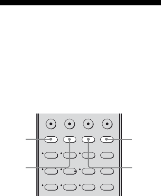
58US
If you connect a subwoofer
This receiver will generate a low frequency
signal for output to the subwoofer when there
is no LFE signal, which is a low-pass sound
effect output from a subwoofer to a 2 channel
signal. However, the low frequency signal is
not generated for “NEO6 CIN” or “NEO6
MUS” when all speakers are set to “LARGE”.
Notes
• This function does not work when ANALOG
DIRECT is selected.
• Dolby Pro Logic IIx decoding does not function for
DTS format signals or for signals with a sampling
frequency of more than 48 kHz.
Tip
When a multi channel signal is input, only Dolby
Pro Logic IIx decoding is effective. When you select
decoding modes other than Dolby Pro Logic IIx,
multi channel sound (being encoded) is output.
Selecting a pre-
programmed sound field
You can take advantage of surround sound
simply by selecting one of the receiver’s pre-
programmed sound fields. They bring the
exciting and powerful sound of movie theaters
and concert halls into your home.
Press MOVIE repeatedly to select a
sound field for movies or press
MUSIC repeatedly to select a
sound field for music.
For details, see “Types of sound field
available” (page 59).
123
46
789
2CH A.F.D. MOVIE MUSIC
DVD/BD
MENU
AUTO CAL
D.TUNING
D.SKIP
THEATER
SAT TV SA-CD/CD TUNER
5
MUSIC
MOVIE
2CH
A.F.D.

59US
Enjoying Surround Sound
Types of sound field available
* You can only select this sound field if the headphones are connected to the receiver.
Sound field
for
Sound field
[Display]
Effect
Movie CINEMA STUDIO EX A
DCS [C.ST.EX A]
Reproduces the sound characteristics of the Sony Pictures
Entertainment “Cary Grant Theater” cinema production
studio. This is a standard mode, great for watching almost any
type of movie.
CINEMA STUDIO EX B
DCS [C.ST.EX B]
Reproduces the sound characteristics of the Sony Pictures
Entertainment “Kim Novak Theater” cinema production
studio. This mode is ideal for watching science-fiction or
action movies with lots of sound effects.
CINEMA STUDIO EX C
DCS [C.ST.EX C]
Reproduces the sound characteristics of the Sony Pictures
Entertainment scoring stage. This mode is ideal for watching
musicals or films where orchestra music is featured in the
soundtrack.
Music HALL [HALL] Reproduces the acoustics of a classical concert hall.
JAZZ CLUB [JAZZ] Reproduces the acoustics of a jazz club.
LIVE CONCERT
[CONCERT]
Reproduces the acoustics of a 300-seat live house.
STADIUM [STADIUM] Reproduces the feeling of a large open-air stadium.
SPORTS [SPORTS] Reproduces the feeling of sports broadcasting.
PORTABLE AUDIO
ENHANCER [PORTABLE]
Reproduces a clear enhanced sound image from your portable
audio device. This mode is ideal for MP3 and other
compressed music.
Headphone* HEADPHONE 2CH
[HP 2CH]
This mode is selected automatically if you use headphones
when 2 channel mode (page 60)/A.F.D. mode (page 57) is
selected. Standard 2 channel stereo sources completely bypass
the sound field processing and multi channel surround formats
are downmixed to 2 channels.
HEADPHONE DIRECT
[HP DIR]
Outputs the analog signals without processing by the tone,
sound field, etc.
continued
60US
Notes
• The effects provided by the virtual speakers may
cause increased noise in the playback signal.
• When listening with sound fields that employ the
virtual speakers, you will not be able to hear any
sound coming directly from the surround speakers.
• This function does not work when:
– ANALOG DIRECT is selected.
– signals with a sampling frequency of more than
48 kHz is input.
– the multi channel Linear PCM signals are
received via an HDMI IN jack.
• When one of the sound fields for music is selected,
no sound is output from the subwoofer if all the
speakers are set to “LARGE” on the SYSTEM
menu. However, the sound will be output from the
subwoofer if
– the digital input signal contains LFE signals.
– the front and surround speakers are set to
“SMALL”.
– the sound field for movie is selected.
Tips
• You can identify the encoding format of DVD
software, etc., by looking at the logo on the
package.
• Sound fields with DCS mark use DCS
technology. See “Glossary” (page 97).
To turn off the surround effect
for movie/music
Press 2CH to select “2CH ST.” or press A.F.D.
repeatedly to select “A.F.D. AUTO”.
Using only the front
speakers
(2CH STEREO)
In this mode, the receiver outputs the sound
from the front left/right speakers only. There is
no sound from the subwoofer.
Standard 2 channel stereo sources completely
bypass the sound field processing and multi
channel surround formats are downmixed to 2
channel.
Press 2CH.
Note
No sound is output from the subwoofer in the 2CH
STEREO mode. To listen to 2 channel stereo
sources using the front left/right speakers and a
subwoofer, select “A.F.D. AUTO” (page 57).
123
VIDEO1 VIDEO2 BD DVD
2CH A.F.D. MOVIE MUSIC
THEATER
SAT TV SA-CD/CD TUNER
2CH
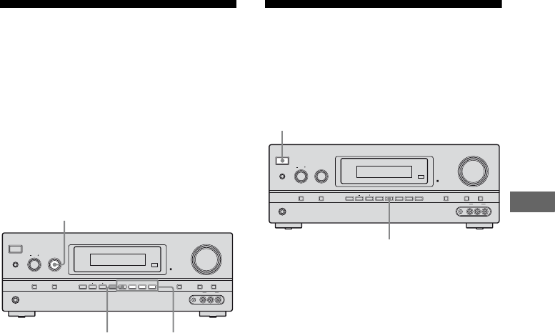
61US
Enjoying Surround Sound
Listening to the sound
without any adjustment
(ANALOG DIRECT)
You can switch the audio of the selected input
to two channel analog input. This function
enables you to enjoy high quality analog
sources.
When using this function, only the volume and
front speaker balance can be adjusted.
1Turn INPUT SELECTOR on the
receiver to select the input you
want to listen to in analog
audio.
You can also use the input buttons on the
remote.
2Press 2CH/A.DIRECT
repeatedly on the receiver to
select “A.DIRECT”.
The analog audio is output.
To cancel ANALOG DIRECT
Press 2CH/A.DIRECT on the receiver again.
You can also press any sound field buttons.
Notes
• When headphones are connected, “HP DIR”
appears on the display.
• This function is not available when DMPORT and
DVD input is selected.
Resetting sound fields to
the initial settings
Be sure to use the buttons on the receiver for
this operation.
1Press ?/1 to turn off the power.
2While holding down 2CH/
A.DIRECT, press ?/1.
“S.F. CLR.” appears on the display and
all sound fields are reset to their initial
setting.
?/1
PHONES
SPEAKERS
INPUT SELECTOR
INPUT MODE TUNING MODE
MASTER VOLUME
TONE MODE DISPLAY DIMMER MUTING
MEMORY/
ENTER 2CH/
A.DIRECT A.F.D. MOVIE MUSICTUNING
TONE
VIDEO 2 IN
VIDEO L AUDIO RAUTO CAL MIC
INPUT SELECTOR
2CH/
A.DIRECT
Sound field
buttons
?/1
PHONES
SPEAKERS
INPUT SELECTOR
INPUT MODE TUNING MODE
MASTER VOLUME
TONE MODE DISPLAY DIMMER MUTING
MEMORY/
ENTER 2CH/
A.DIRECT A.F.D. MOVIE MUSICTUNING
TONE
VIDEO 2 IN
VIDEO L AUDIO RAUTO CAL MIC
?/1
2CH/A.DIRECT
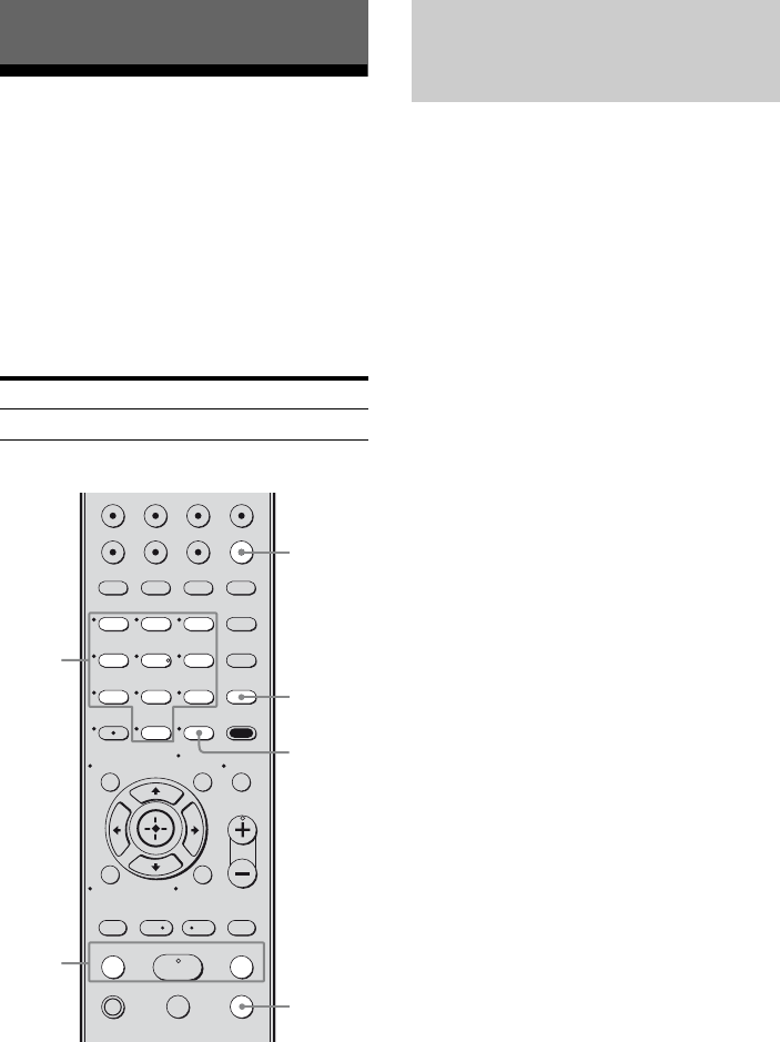
62US
Listening to FM/AM radio
You can listen to FM and AM broadcasts
through the built-in tuner. Before operation,
make sure you have connected the FM and
AM antennas (aerials) to the receiver (page
28).
Tip
The tuning scale for direct tuning differs depending
on the area code as shown in the following table. For
details on area codes, see page 4.
* The AM tuning scale can be changed (page 63).
1Press TUNER repeatedly to
select the FM or AM band.
2Press TUNING + or TUNING –.
Press TUNING + to scan from low to
high; press TUNING – to scan from high
to low.
The receiver stops scanning whenever a
station is received.
Using the controls on the
receiver
1Turn INPUT SELECTOR to select the FM
or AM band.
2Press TUNING MODE repeatedly to select
“AUTO T.”.
3Press TUNING + or TUNING –.
In case of poor FM stereo
reception
If the FM stereo reception is poor and “ST”
flashes on the display, select monaural audio
so that the sound will be less distorted.
Press FM MODE repeatedly until the
“MONO” indicator lights up on the display.
To return to stereo mode, press FM MODE
repeatedly until the “MONO” indicator on the
display does not light up.
Tuner Operations
Area code FM AM
U, CA 100 kHz 10 kHz*
123
46
78
0/10
ENTER
9
VIDEO1 VIDEO2 BD DVD
2CH A.F.D.
TV CH –
PRESET –
TV CH +
PRESET +
TUNING –
TV
TUNING +
FM MODE
MOVIE MUSIC
AMP MENU
CLEAR
DISPLAY MUTING
TV VOL
MASTER VOL
DVD/BD
MENU
AUTO CAL
D.TUNING
D.SKIP
THEATER
SAT TV SA-CD/CD TUNER
.
HmM
Xx
<
<
>
5
>10
REPLAY ADVANCE
– CATEGORY +
CATEGORY MODE
MEMORY
O
TOOLS/
OPTIONS
RETURN/EXIT
MENU/HOME
TUNING
+/–
TUNER
D.TUNING
ENTER
FM MODE
Numeric
buttons
Tuning into a station
automatically (Automatic
Tuning)

63US
Tuner Operations
Enter the frequency of a station directly by
using the numeric buttons.
1Press TUNER repeatedly to
select the FM or AM band.
You can also use INPUT SELECTOR on
the receiver.
2Press D.TUNING.
3Press the numeric buttons to
enter the frequency.
Example 1: FM 102.50 MHz
Select 1 b 0 b 2 b 5 b 0
Example 2: AM 1,350 kHz
Select 1 b 3 b 5 b 0
If you have tuned in an AM station, adjust
the direction of the AM loop antenna
(aerial) for optimum reception.
4Press ENTER.
You can also use MEMORY/ENTER on
the receiver.
If you cannot tune in a station
Make sure you have entered the right
frequency. If not, repeat steps 2 to 4. If you
still cannot tune in a station, the frequency is
not used in your area.
(Models of area code U, CA only)
You can change the AM tuning scale to either
9 kHz or 10 kHz using the buttons on the
receiver.
1Press ?/1 to turn off the
receiver.
2While holding down TUNING
MODE, press ?/1.
3Change the current AM tuning
scale to 9 kHz (or 10 kHz).
To reset the scale to 10 kHz (or 9 kHz),
repeat the procedure above.
Note
All preset stations will be erased when you change
the tuning scale.
Tuning into a station directly
(Direct Tuning)
Changing the AM tuning scale
?/1
PHONES
SPEAKERS
INPUT SELECTOR
INPUT MODE TUNING MODE
MASTER VOLUME
TONE MODE DISPLAY DIMMER MUTING
MEMORY/
ENTER 2CH/
A.DIRECT A.F.D. MOVIE MUSICTUNING
TONE
VIDEO 2 IN
VIDEO L AUDIO RAUTO CAL MIC
?/1
TUNING MODE
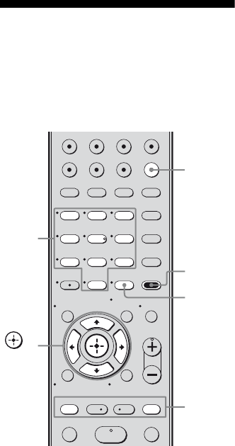
64US
Presetting FM/AM radio
stations
You can preset up to 30 FM stations and 30
AM stations. Then you can easily tune in the
stations you often listen to.
1Press TUNER repeatedly to
select the FM or AM band.
You can also use INPUT SELECTOR on
the receiver.
2Tune in the station that you
want to preset using Automatic
Tuning (page 62) or Direct
Tuning (page 63).
In case of poor FM stereo reception,
switch the FM reception mode (page 62).
3Press MEMORY.
You can also use MEMORY/ENTER on
the receiver.
“MEMORY” lights up for a few seconds.
Perform steps 4 and 5 before
“MEMORY” goes out.
4Press the numeric buttons to
select a preset number.
You can also press PRESET + or
PRESET – to select a preset number.
If “MEMORY” goes out before you
select the preset number, start again from
step 3.
5Press ENTER.
You can also use MEMORY/ENTER on
the receiver.
The station is stored as the selected preset
number.
If “MEMORY” goes out before you press
ENTER, start again from step 3.
6Repeat steps 1 to 5 to preset
another station.
123
46
78
0/10
ENTER
9
VIDEO1 VIDEO2 BD DVD
2CH A.F.D.
TV CH –
PRESET –
TV CH +
PRESET +
TUNING – TUNING +
MOVIE MUSIC
AMP MENU
CLEAR
DISPLAY MUTING
TV VOL
MASTER VOL
DVD/BD
MENU
AUTO CAL
D.TUNING
D.SKIP
THEATER
SAT TV SA-CD/CD TUNER
.
HmM
<
<
>
5
>10
REPLAY ADVANCE
– CATEGORY +
CATEGORY MODE
MEMORY
O
TOOLS/
OPTIONS
RETURN/EXIT
MENU/HOME
TUNER
AMP
MENU
PRESET
+/–
Numeric
buttons
MEMORY,
ENTER
,
V/v/B/b
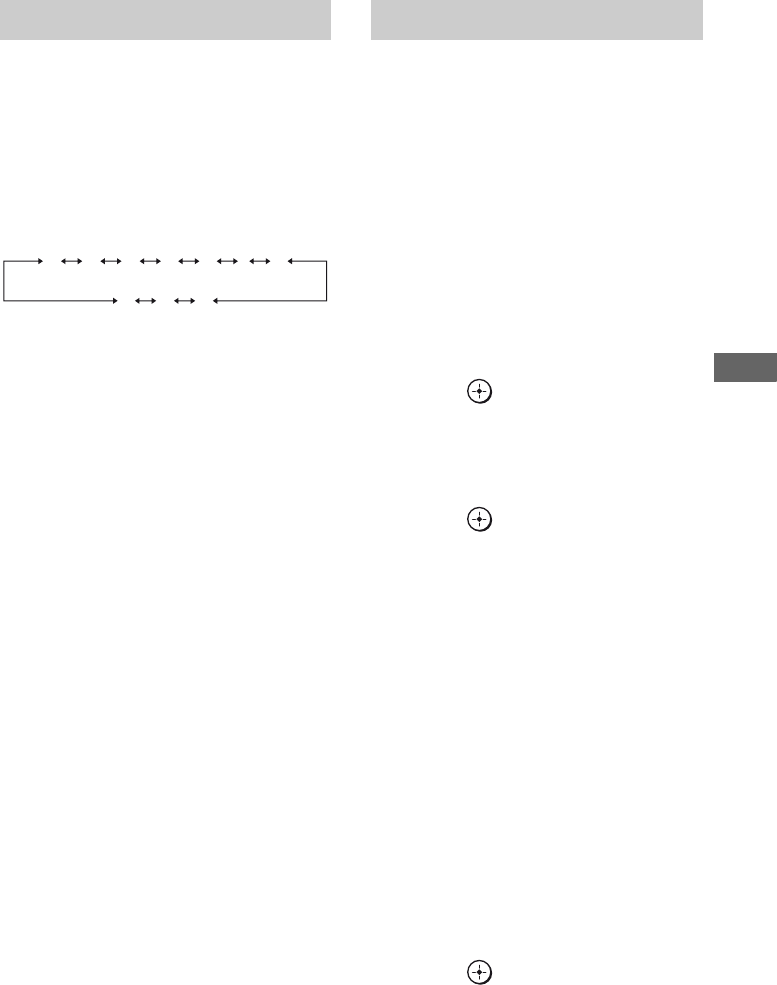
65US
Tuner Operations
1Press TUNER repeatedly to
select the FM or AM band.
2Press PRESET + or PRESET –
repeatedly to select the preset
station you want.
Each time you press the button, you can
select a preset station as follows:
You can also press the numeric buttons to
select the preset station you want. Then,
press ENTER to enter the selection.
Using the controls on the
receiver
1Turn INPUT SELECTOR to select the FM
or AM band.
2Press TUNING MODE repeatedly to select
“PRESET T.”.
3Press TUNING + or TUNING – to select the
preset station you want.
1Press TUNER repeatedly to
select the FM or AM band.
You can also use INPUT SELECTOR on
the receiver.
2Tune in the preset station you
want to create an index name
for (page 65).
3Press AMP MENU.
“1-LEVEL” appears on the display.
4Press V/v repeatedly to select
“4-TUNER”.
5Press or b to enter the
menu.
6Press V/v repeatedly to select
“NAME IN”.
7Press or b to enter the
parameter.
The cursor flashes and you can select a
character.
8Press V/v to select a character,
then press B/b to move the
cursor to the next position.
If you made a mistake
Press B/b until the character you want to
change flashes, then press V/v to select
the correct character.
Tips
•You can select the character type as follows
by pressing V/v.
Alphabet (upper case) t Numbers t
Symbols
•To enter a blank space, press b without
selecting a character.
9Press .
The name you entered is registered.
Tuning to preset stations
01 02 03 04 05 27...
30 29 28
Naming preset stations

66US
Listening to Satellite
Radio
To listen to Satellite Radio, you’ll need to
connect a SIRIUS Satellite Radio tuner (sold
separately) to your Sirius-Ready receiver.
SIRIUS Satellite Radio is available to
residents of the US (except Alaska and
Hawaii) and Canada.
Satellite Radio delivers a variety of
commercial-free music from categories
ranging from Pop, Rock, Country, R&B,
Dance, Jazz, Classical and many more plus
coverage of all the top professional and
college sports including play by play games
from select leagues and teams. Additional
programming includes expert sports talk,
uncensored entertainment, comedy, family
programming, local traffic and weather and
news from your most trusted sources.
Once you’ve purchased a SIRIUS tuner you’ll
need to activate it and subscribe to begin
enjoying the service. Easy to follow
installation and setup instructions are provided
with the SIRIUS tuner. There are a variety of
programming packages available, including
the option of adding “The Best of XM”
programming to the SIRIUS service. The
“Best of XM” service is not available to
SIRIUS Canada subscribers at this time.
Please check with SIRIUS Canada for any
updates using the numbers and web address
below.
Family friendly packages are also available to
restrict channels featuring content that may be
inappropriate for children.
To subscribe to SIRIUS, U.S. and Canadian
customers can call 1-888-539-SIRI (1-888-
539-7474) or visit sirius.com (US) or
siriuscanada.ca (Canada).
SIRIUS and all related marks and logos are
trademarks of Sirius XM Radio Inc. and its
subsidiaries. All other marks and logos are the
property of their respective owners. All rights
reserved. SIRIUS subscription sold separately.
Taxes and a one-time activation fee may apply.
SIRIUS tuner required (sold separately) to receive
the SIRIUS service. All programming and fees
subject to change. It is prohibited to copy,
decompile, disassemble, reverse engineer, hack,
manipulate or otherwise make available any
technology or software incorporated in receivers
compatible with the SIRIUS Satellite Radio System.
Service not available in Alaska or Hawaii.
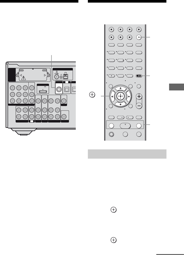
67US
Tuner Operations
Connecting the SIRIUS
Satellite Radio
Connect the SiriusConnect Home tuner. When
you use the SiriusConnect Home tuner with
this receiver, be sure to connect the AC power
adaptor supplied with the tuner to a wall outlet.
Note
Keep the SiriusConnect Home tuner, antenna, and
AC power adaptor away from the speaker cords and
the power cord to avoid picking up noise.
Preparing to listen to the
SIRIUS Satellite Radio
1Press TUNER repeatedly to
select “SIRIUS”.
2Press AMP MENU.
“1-LEVEL” appears on the display.
3Press V/v repeatedly to select
“4-TUNER”.
4Press or b to enter the
menu.
5Press V/v repeatedly to select
“SR ID”.
6Press or b.
The first 6 digits appear on the display.
L
R
DIG
I
DC5V
0.7A MAX
ANTENNA
DMPORT
SIRIUS
SAT
IN
AM
Y
P
B
/
C
B
COMPONENT VIDEO
OUT IN
P
R
/
C
R
DVD
IN
VIDEO 1
IN
MONITOR
OUT
SA-CD
/
CD
/
CD-R
VIDEO 1
IN
TV
TV
AUDIO
IN
VIDEO
IN
SAT
AUDIO
OUT
AUDIO
OUT
VIDEO
OUT
VIDEO
OUT
IN
OPTICAL
AUDIO
IN
VIDEO
IN
SUBWOOFER
MONITOR
AUDIO
IN
VIDEO
IN
BD
OPTIC
A
EZW-T100
SIRIUS jack
Checking the SIRIUS Radio ID
123
46
78
0/10
ENTER
9
VIDEO1 VIDEO2 BD DVD
2CH A.F.D.
TV CH –
PRESET –
TV CH +
PRESET +
TUNING –
TV
TUNING +
FM MODE
MOVIE MUSIC
AMP MENU
CLEAR
DISPLAY MUTING
TV VOL
MASTER VOL
DVD/BD
MENU
AUTO CAL
D.TUNING
D.SKIP
THEATER
SAT TV SA-CD/CD TUNER
.
HmM
Xx
<
<
>
5
>10
REPLAY ADVANCE
– CATEGORY +
CATEGORY MODE
MEMORY
O
TOOLS/
OPTIONS
RETURN/EXIT
MENU/HOME
TUNER
AMP
MENU
TUNING
+/–
,
V/v/B/b
continued
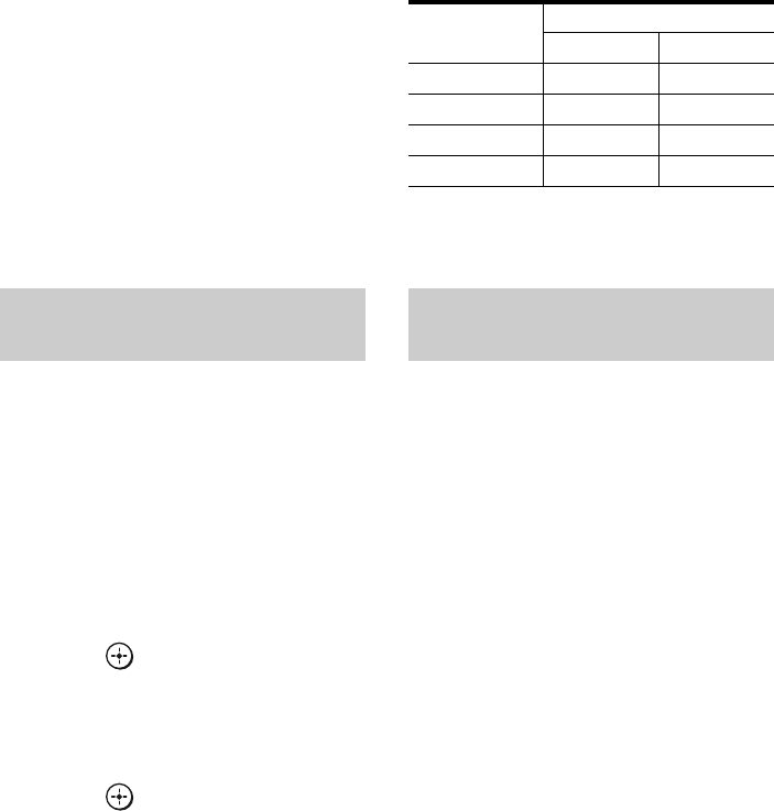
68US
7Press b.
The last 6 digits appear on the display.
8Check the SIRIUS ID on the
display and write it in the space
provided here.
SIRIUS ID:_______________________
Using the controls on the
receiver
1Turn INPUT SELECTOR to select
“SIRIUS”.
2Press TUNING MODE repeatedly to select
“AUTO T.”, and then press TUNING + or
TUNING – to select channel 0.
3Check the SIRIUS ID on the display and
write it in the space provided here.
SIRIUS ID:_______________________
1Press TUNER repeatedly to
select “SIRIUS”.
You can also use INPUT SELECTOR on
the receiver.
2Press AMP MENU.
“1-LEVEL” appears on the display.
3Press V/v repeatedly to select
“4-TUNER”.
4Press or b to enter the
menu.
5Press V/v repeatedly to select
“SR ANT”.
6Press or b to enter the
parameter.
7While checking the parameter,
aim your antenna to where the
best reception will be received.
For details on the parameter, see “SIRIUS
Signal strength” below.
SIRIUS Signal strength
When you have finished
Press AMP MENU.
1Press TUNER repeatedly to
select “SIRIUS”.
You can also use INPUT SELECTOR on
the receiver.
2Press TUNING + or TUNING – to
select a channel.
You can also press TUNING MODE on
the receiver to select “AUTO T.”, and
then press TUNING + or TUNING – to
select a channel.
Checking receiving conditions
(SIRIUS Antenna Aiming)
Signal
strength
Signal type
Satellite Terrestrial
EXC (excellent) S : 3 T : 3
GOOD S : 2 T : 2
WEAK S : 1 T : 1
NONE S : 0 T : 0
Receiving SIRIUS Satellite Radio
broadcasts
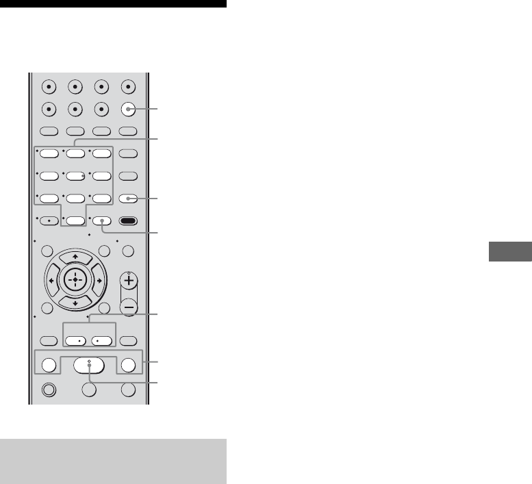
69US
Tuner Operations
Selecting a channel of the
SIRIUS Satellite Radio
You can select a channel from one category or
all the categories by changing the category
mode.
1Press TUNER repeatedly to
select “SIRIUS”.
You can also use INPUT SELECTOR on
the receiver.
2Press CATEGORY MODE
repeatedly to select the “ONE
CAT”.
• ALL CAT: You can select a channel
from all the categories. The initial
setting is “ALL CAT”.
• ONE CAT: You can select a channel
from one category. “CAT” is displayed
on the display when you set to “ONE
CAT” mode.
3Press CATEGORY + or
CATEGORY – to select the
category you want.
The category is selected and the channel
with the lowest number in the specified
category is selected.
4Press TUNING + or TUNING – to
select the channel.
You can also press TUNING MODE on
the receiver to select “AUTO T.”, and
then press TUNING + or TUNING – to
select a channel.
Notes
• When you select a channel in the “ONE CAT”
mode, the channel you selected may not be the one
in the category you want. This is because one
channel may belong to more than one category.
• If you press CATEGORY + or CATEGORY – in
the “ALL CAT” mode, the first channel of the next
or previous category is selected (CATEGORY
SKIP).
Selecting channels from a
category (CATEGORY TUNING)
123
46
78
0/10
ENTER
9
VIDEO1 VIDEO2 BD DVD
2CH A.F.D.
TV CH –
PRESET –
TV CH +
PRESET +
TUNING –
TV
TUNING +
FM MODE
MOVIE MUSIC
AMP MENU
CLEAR
DISPLAY MUTING
TV VOL
MASTER VOL
DVD/BD
MENU
AUTO CAL
D.TUNING
D.SKIP
THEATER
SAT TV SA-CD/CD TUNER
.
HmM
Xx
<
<
>
5
>10
REPLAY ADVANCE
– CATEGORY +
CATEGORY MODE
MEMORY
O
TOOLS/
OPTIONS
RETURN/EXIT
MENU/HOME
TUNER
D.TUNING
TUNING +/–
Numeric
buttons
ENTER
CATEGORY
+/–
CATEGORY
MODE
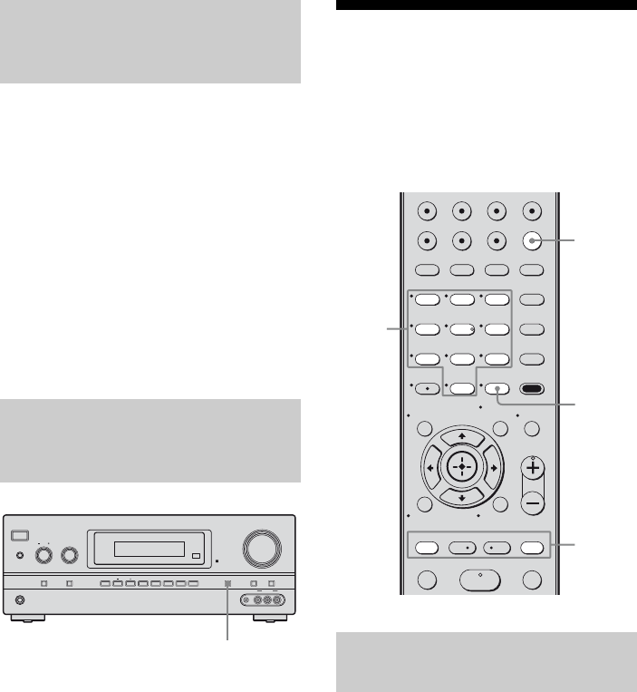
70US
1Press TUNER repeatedly to
select “SIRIUS”.
You can also use INPUT SELECTOR on
the receiver.
2Press D.TUNING.
3Press the numeric buttons to
enter the channel number.
4Press ENTER.
You can also use MEMORY/ENTER on
the receiver.
The selected channel is tune in.
Press DISPLAY on the receiver
repeatedly.
Each time you press DISPLAY while tuning in
the channel, the display changes cyclically as
follows:
Channel name t Channel number t
Category name t Artist name/Feature t
Song/Program title t Composer name t
Signal strength t Sound field type
Presetting SIRIUS
Satellite Radio channels
You can select the channels you want directly
by presetting them using the preset numbers.
You can preset up to 30 SIRIUS Satellite
Radio channels.
1Press TUNER repeatedly to
select “SIRIUS”.
You can also use INPUT SELECTOR on
the receiver.
2Select a channel you want to
preset using Category Tuning
(page 69) or Direct Tuning
(page 70).
Selecting channels by inputting
the channel number directly
(DIRECT TUNING)
Displaying the SIRIUS Satellite
Radio information on the front
panel display
?/1
PHONES
SPEAKERS
INPUT SELECTOR
INPUT MODE TUNING MODE
MASTER VOLUME
TONE MODE DISPLAY DIMMER MUTING
MEMORY/
ENTER 2CH/
A.DIRECT A.F.D. MOVIE MUSICTUNING
TONE
VIDEO 2 IN
VIDEO L AUDIO RAUTO CAL MIC
DISPLAY Presetting channels using the
preset numbers
123
46
78
0/10
ENTER
9
VIDEO1 VIDEO2 BD DVD
2CH A.F.D.
TV CH –
PRESET –
TV CH +
PRESET +
TUNING – TUNING +
MOVIE MUSIC
AMP MENU
CLEAR
DISPLAY MUTING
TV VOL
MASTER VOL
DVD/BD
MENU
AUTO CAL
D.TUNING
D.SKIP
THEATER
SAT TV SA-CD/CD TUNER
.
HmM
<
<
>
5
>10
REPLAY ADVANCE
– CATEGORY +
CATEGORY MODE
MEMORY
O
TOOLS/
OPTIONS
RETURN/EXIT
MENU/HOME
TUNER
PRESET
+/–
Numeric
buttons
MEMORY,
ENTER

71US
Tuner Operations
3Press MEMORY.
You can also use MEMORY/ENTER on
the receiver.
4Press the numeric buttons to
select a preset number you
want to use as the preset
channel.
You can also select the number by
pressing PRESET + or PRESET –.
You can also press TUNING + or
TUNING – on the receiver.
Preset channels from 1 to 30 are available,
and channel 184 is preset for all the preset
channels when you purchase the receiver.
5Press ENTER.
You can also use MEMORY/ENTER on
the receiver.
The selected channel is registered as the
preset channel you selected in step 1.
6Repeat steps 2 to 5 to preset
another channel.
You can store channels from 1 to 30.
1Press TUNER repeatedly to
select “SIRIUS”.
You can also use INPUT SELECTOR on
the receiver.
2Press PRESET + or PRESET –
repeatedly to select the preset
channel you want.
You can also press the numeric buttons to
select the preset channel you want. Then
press ENTER to enter the selection.
You can also press TUNING MODE on
the receiver to select “PRESET T.”, and
then press TUNING + or TUNING –.
You can select preset channels from 1 to
30.
Note
The channel information you have preset may be
changed if Sirius XM Radio Inc. change their
channel programming.
Selecting the channel by using
the preset numbers
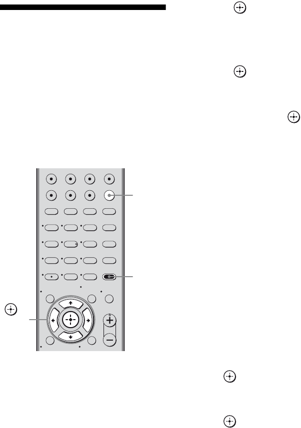
72US
Restricting access to
specific channels
(Parental Lock) (SIRIUS
only)
You can restrict access to certain channels
using your own lock code. The lock code is set
to “0000” as the default.
Change the lock code before you use this
function for the first time. See “To change the
lock code (Lock Code)” (page 72).
1Press TUNER repeatedly to
select “SIRIUS”.
You can also use INPUT SELECTOR on
the receiver.
2Select a channel you want to
lock using Category Tuning
(page 69) or Direct Tuning
(page 70).
3Press AMP MENU.
“1-LEVEL” appears on the display.
4Press V/v repeatedly to select
“4-TUNER”.
5Press or b to enter the
menu.
6Press V/v repeatedly to select
“PARENTAL”.
7Press or b to enter the
parameter.
8Press V/v repeatedly to select
“ON”, then press .
“LOCK” appears on the display.
9Enter your 4-digit lock code
using the numeric buttons.
“LOCKED” appears on the display and
the Parental Lock is set.
To delete the numbers you have entered,
repeat the procedure above from step 3.
Select “OFF” in step 8.
To change the lock code
(Lock Code)
1Press TUNER repeatedly to select
“SIRIUS”.
You can also use INPUT SELECTOR on
the receiver.
2Press AMP MENU.
“1-LEVEL” appears on the display.
3Press V/v repeatedly to select
“4-TUNER”.
4Press or b to enter the menu.
5Press V/v repeatedly to select “CODE
EDT.”.
6Press or b to enter the parameter.
“CODE” appears on the display.
7Enter your 4-digit lock code using the
numeric buttons.
“NEW” appears on the display.
8Enter a new 4-digit lock code using the
numeric buttons.
“CONF.” appears on the display.
123
46
78
0/10
ENTER
9
VIDEO1 VIDEO2 BD DVD
2CH A.F.D. MOVIE MUSIC
AMP MENU
CLEAR
DISPLAY MUTING
TV VOL
MASTER VOL
DVD/BD
MENU
AUTO CAL
D.TUNING
D.SKIP
THEATER
SAT TV SA-CD/CD TUNER
5
>10
MEMORY
O
TOOLS/
OPTIONS
RETURN/EXIT
MENU/HOME
TUNER
AMP
MENU
,
V/v/B/b

73US
Tuner Operations
9Reenter the new lock code with the
numeric buttons.
“CHANGED” appears on the display.
To listen to the locked channels
1Press TUNER repeatedly to select
“SIRIUS”.
You can also use INPUT SELECTOR on
the receiver.
2Select a locked channel you want to
listen using Direct Tuning (page 70).
“LOCKED” appears on the display.
3Enter your 4-digit lock code using the
numeric buttons.
The channel is tuned in.
To cancel the Parental Lock
1Press TUNER repeatedly to select
“SIRIUS”.
You can also use INPUT SELECTOR on
the receiver.
2Select a channel you want to unlock
using Direct Tuning (page 70).
“LOCKED” appears on the display.
3Enter your 4-digit lock code using the
numeric buttons.
The channel is tuned in.
4Press AMP MENU.
“1-LEVEL” appears on the display.
5Press V/v repeatedly to select
“4-TUNER”.
6Press or b to enter the menu.
7Press V/v repeatedly to select
“PARENTAL”.
8Press or b to enter the parameter.
9Press V/v repeatedly to select “OFF”,
then press .
“LOCK” appears on the display.
10Enter your 4-digit lock code using the
numeric buttons.
“UNLOCKED” appears on the display.
Notes
• When you select a channel using Category Tuning,
locked channels are skipped.
• When the receiver is reset to the factory settings,
the lock code returns to the default (0000), but the
Parental Lock settings are not removed.
• You cannot preset locked channels. If you set the
Parental Lock for a preset channel, the preset
information for that channel returns to the default.
• You cannot set the Parental Lock for channel 0 or
channel 184.
continued

74US
SIRIUS Satellite Radio message list
* “ANTENNA” and “ERROR” appears on the display alternately.
** “CALL 888” and “539-SIRI” appears on the display alternately.
Message
appears
Explanation Remedies
ANTENNA
ERROR*
The antenna is not connected
properly.
Check the connection between the SiriusConnect
Home tuner and the antenna.
LINKING The receiving condition is not
good.
Try moving the antenna to another location.
For details about the antenna location, see the
instructions supplied with the SiriusConnect Home
tuner.
CALL 888
539-SIRI**
You have not subscribed for the
selected channel.
—
SR TUNER The SiriusConnect Home tuner is
not connected properly.
Check all the connections, and then turn the system on
again. Also make sure if the AC adaptor supplied with
the SiriusConnect Home tuner is connected to a wall
socket.
INVALID You have entered an invalid
channel number.
The channel to be tuned-in is void due to the change
by the broadcast service, or the receiving condition is
not good.
LOCKED The selected channel is locked. —
SUB UPDT The subscription information has
been updated.
—
UPDATING Channel information is being
updated.
—
FW UPDT The SiriusConnect Home tuner
firmware is being updated.
—
–––– There is no text information in the
channel.
This is not an error. The text information may not be
displayed depending on the system condition, for
example, right after the system has received a channel.

75US
“BRAVIA” Sync Features
What is “BRAVIA” Sync?
“BRAVIA” Sync is compatible with a Sony
TV, Blu-ray Disc/DVD player, AV amplifier,
etc., that is equipped with the Control for
HDMI function.
By connecting Sony components that are
compatible with the “BRAVIA” Sync with an
HDMI cable (not supplied), operation is
simplified as follows:
• One-Touch Play: When you play back a
component such as a DVD/Blu-ray disc
player, the receiver and the TV will switch to
the appropriate HDMI input automatically.
In case the receiver or/and the TV is in
standby mode, they will be turned on
automatically.
• System Audio Control: While watching TV,
you can select to output the sound from the
TV speaker or the speakers connected to the
receiver.
• System Power Off: When you turn off the
TV, the receiver and connected components
are also turned off simultaneously.
Control for HDMI is a mutual control function
standard used by HDMI CEC (Consumer
Electronics Control) for HDMI (High-
Definition Multimedia Interface).
The Control for HDMI function
does not work in the following
cases:
• When you connect the receiver to a
component which does not correspond with
Sony Control for HDMI function.
• When you connect the receiver and
components using other than HDMI
connection.
We recommend that you connect the receiver
to products featuring “BRAVIA” Sync.
Note
Depending on the connected component, the
Control for HDMI function may not work. Refer to
the operating instructions of the component.
“BRAVIA” Sync Features
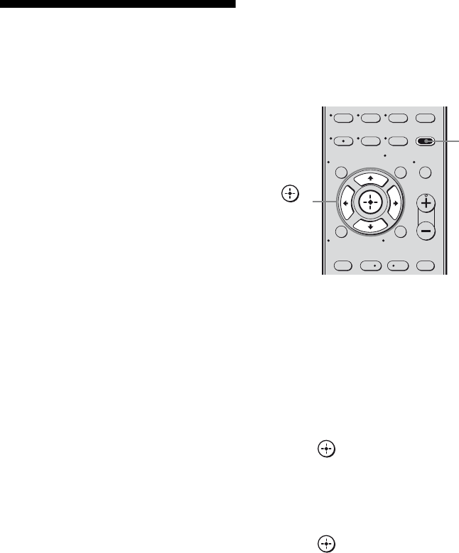
76US
Preparing for the
“BRAVIA” Sync
To use the “BRAVIA” Sync, turn the Control
for HDMI function on for both the receiver
and the connected component. The receiver is
compatible with the “Control for HDMI-Easy
Setting” function.
When your TV is compatible
with the “Control for HDMI-Easy
Setting” function
When you connect a Sony TV with the
“Control for HDMI-Easy Setting” function,
the Control for HDMI function of the receiver
can be turned on simultaneously by turning the
Control for HDMI function of the TV on.
1Make sure that the receiver, TV, and
playback components are connected
using an HDMI cable (not supplied).
(The respective components must be
compatible with the Control for HDMI
function.)
2Turn on the receiver, TV and playback
components.
3Turn the Control for HDMI function of
the TV on.
The Control for HDMI function of the
receiver and all the connected components
are simultaneously turned on. During
setup, “CONTROL”, “SCAN FOR” and
“HDMI” appear sequentially in the display,
and once setting is completed,
“COMPLETE” will appear. Wait until the
setup is complete.
For details on setting the TV, refer to the
operating instructions supplied with the TV.
When your TV is not compatible
with the “Control for HDMI-Easy
Setting” function
Turn the Control for HDMI function of the
receiver and the connected component on
individually.
1Perform the steps given in “When your
TV is compatible with the “Control for
HDMI-Easy Setting” function”
(page 76).
2Press AMP MENU.
“1-LEVEL” appears on the display.
3Press V/v repeatedly to select “6-
HDMI”.
4Press or b to enter the menu.
5Press V/v repeatedly to select
“CONTROL FOR HDMI”.
“CONTROL FOR HDMI” scrolls across
the display, then “CONTROL” appears.
6Press or b to enter the parameter.
7Press V/v repeatedly to select “CTRL
ON”.
Control for HDMI function is activated.
8Select the HDMI input of the receiver
and TV to match the HDMI input of the
connected component, so that the
image from the connected component
is displayed.
78
0/10
ENTER
9
TV CH –
PRESET –
TV CH +
PRESET +
AMP MENU
CLEAR
DISPLAY MUTING
TV VOL
MASTER VOL
D.TUNING
D.SKIP
.<
<
>
>10
REPLAY ADVANCE
– CATEGORY +
MEMORY
O
TOOLS/
OPTIONS
RETURN/EXIT
MENU/HOME
AMP
MENU
,
V/v/B/b

77US
“BRAVIA” Sync Features
9Set the Control for HDMI function for
the connected component to on.
If the Control for HDMI function for the
connected component is already set to on,
you do not need to change the setting.
10Repeat step 8 and 9 for other
components that you want to use the
Control for HDMI function.
For details on setting the TV and connected
components, refer to the operating instructions
of the respective components.
Notes
• When you unplug the HDMI cable or change the
connection, perform the steps given in “When your
TV is compatible with the “Control for HDMI-
Easy Setting” function” (page 76) or “When your
TV is not compatible with the “Control for HDMI-
Easy Setting” function” (page 76).
• You cannot perform One-Touch Play and System
Audio Control during Control for HDMI-Easy
Setting operation.
• Before you do the Control for HDMI-Easy Setting
from the TV, be sure to turn on the TV, connected
components and receiver.
• If the playback components cannot function after
you have made the settings for Control for HDMI-
Easy Setting, check the Control for HDMI setting
on your TV.
• If the connected components do not support
Control for HDMI-Easy Setting, you need to set
the Control for HDMI function for the connected
components to on before you perform the Control
for HDMI-Easy Setting from the TV.
Watching a DVD
(One-Touch Play)
You can enjoy sound and image from the
components connected to the receiver via
HDMI connections by a simple operation.
Play back a connected component.
The receiver and the TV will switch to the
appropriate HDMI input automatically.
In case the receiver or/and the TV is in standby
mode, they will be turned on automatically.
Watching a DVD/Blu-ray disc by
simple operation
You can also select a connected component,
such as a DVD/Blu-ray disc player using the
TV menu. In this case, the receiver and the TV
switch to the appropriate HDMI input.
Note
Depending on the TV, the start of the content may
not be output.

78US
Enjoying the TV sound
from the speakers
connected to the receiver
(System Audio Control)
You can enjoy the TV sound from the speakers
connected to the receiver by a simple
operation.
You can operate System Audio Control
function using the TV menu. For details, refer
to the operating instructions of the TV.
When System Audio Control function is
turned on, the receiver will turns on and
switches to the appropriate input
automatically.
TV sound is output from the speakers
connected to the receiver, and the volume of
the TV is minimized simultaneously.
You can also use the System Audio Control
function as follows.
• If you turn on the receiver while the TV is
turned on, the System Audio Control
function will automatically be set to on and
the TV sound will output from the speakers
connected to the receiver. However, if you
turn off the receiver, the sound will output
from the TV speakers.
• You can adjust the receiver’s volume when
you adjust the TV volume.
Notes
• If System Audio Control does not function
according to your TV setting, refer to the operating
instructions of the TV.
• When “CONTROL FOR HDMI” is set to “CTRL
ON”, the “AUDIO FOR HDMI” settings in the
HDMI menu will set automatically depending on
the System Audio Control settings.
• When you connect a TV that does not have System
Audio Control function, the System Audio Control
function does not work.
• If the TV is turned on before turning on the
receiver, the TV sound will not be output for a
moment.
• When you switch to an input other than HDMI or
TV, the System Audio Control function will
automatically be set to off.
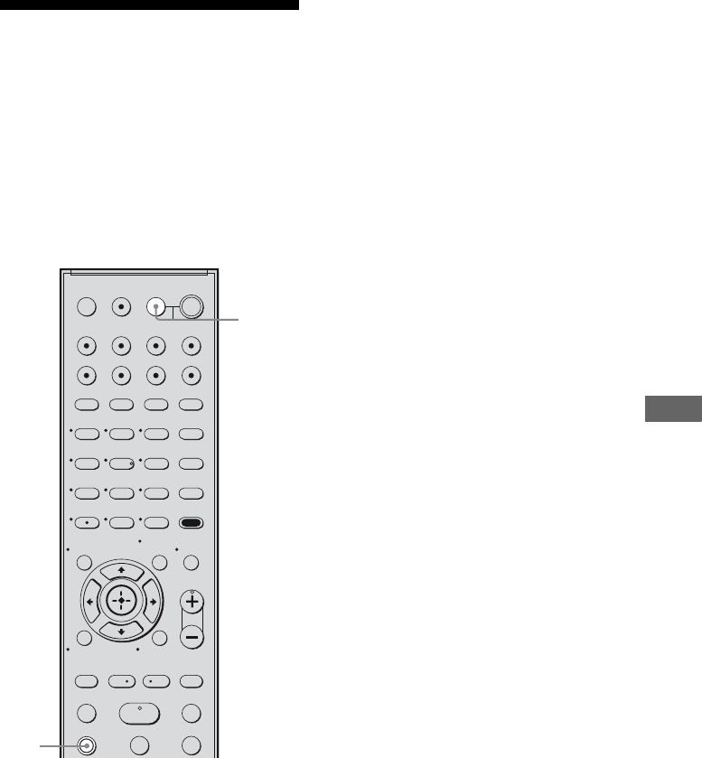
79US
“BRAVIA” Sync Features
Turning off the receiver
with the TV
(System Power Off)
When you turn the TV off by using the
POWER button on the TV’s remote, the
receiver and the connected components turn
off automatically.
You can also use the receiver’s remote to turn
off the TV.
Press TV and TV ?/1 at the same
time.
The TV, receiver and the components
connected via HDMI are turned off.
Notes
• Set the TV Standby Synchro to “ON” before using
the System Power Off function. For details, refer to
the operating instructions of the TV.
• Depending on the status, the connected
components may not be turned off. For details,
refer to the operating instructions of the connected
components.
123
46
78
0/10
ENTER
9
SYSTEM STANDBY
TV INPUT
SLEEP DMPORT
VIDEO1 VIDEO2 BD DVD
2CH A.F.D.
TV CH –
PRESET –
TV CH +
PRESET +
TUNING –
TV
TUNING +
FM MODE
MOVIE MUSIC
AMP MENU
CLEAR
DISPLAY MUTING
TV VOL
MASTER VOL
DVD/BD
MENU
AUTO CAL
D.TUNING
D.SKIP
THEATER
SAT TV SA-CD/CD TUNER
?/1
.
HmM
Xx
<
<
>
5
>10
REPLAY ADVANCE
– CATEGORY +
CATEGORY MODE
MEMORY
O
TV
?/1
AV
?/1
TOOLS/
OPTIONS
RETURN/EXIT
MENU/HOME
TV
TV ?/1
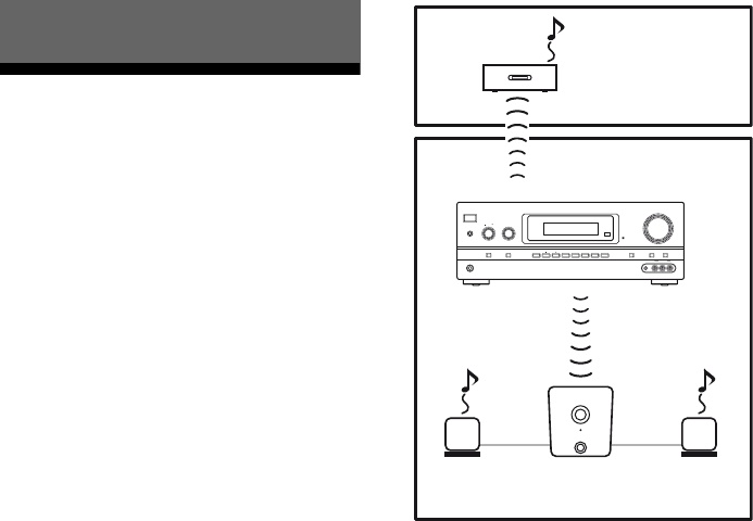
80US
About S-AIR products
This receiver is compatible with the S-AIR
function (page 98), which allows wireless
sound transmission between S-AIR products.
When you purchase the S-AIR product, you
need to establish sound transmission (page
81).
There are two types of S-AIR product.
• S-AIR main unit (this receiver):
The S-AIR main unit is for transmitting
sound.
You can use up to 3 S-AIR main units. (The
number of usable S-AIR main unit depends
on the use environment.)
• S-AIR sub unit (not supplied): The S-AIR
sub unit is for receiving sound.
– Surround amplifier: You can enjoy
surround and surround back speakers
sound wirelessly. For details, refer to the
operating instruction supplied with the
surround amplifier.
– S-AIR receiver: You can enjoy system
sound in another room.
These S-AIR products can be purchased as an
option (the S-AIR product lineup differs
depending on the area).
Notes or instructions for the surround
amplifier or S-AIR receiver in this operating
instructions is refer only when the surround
amplifier or S-AIR receiver is used.
S-AIR Operations
?/1
PHONES
SPEAKERS
INPUT SELECTOR
INPUT MODE TUNING MODE
MASTER VOLUME
TONE MODE DISPLAY DIMMER MUTING
MEMORY/
ENTER 2CH/
A.DIRECT A.F.D. MOVIE MUSICTUNING
TONE
VIDEO 2 IN
VIDEO L AUDIO RAUTO CAL MIC
S-AIR sub unit
(S-AIR receiver)
S-AIR main unit
(this receiver)
S-AIR sub unit
(surround amplifier)
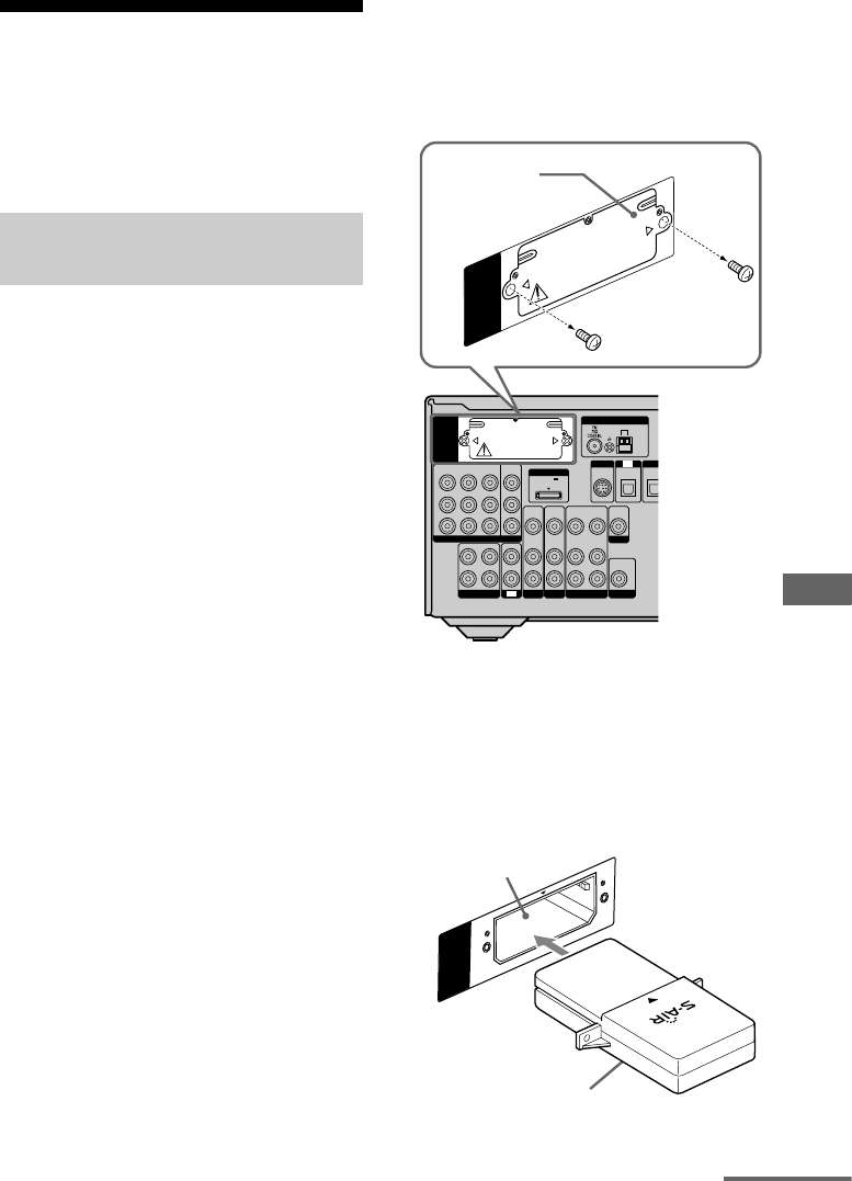
81US
S-AIR Operations
Setting up an S-AIR
product
Before using an S-AIR product, be sure to
perform the following settings to establish the
sound transmission.
To make use of the S-AIR function, you need
to insert the wireless transmitter (not supplied)
into the S-AIR main unit and the wireless
transceiver (not supplied) into the S-AIR sub
unit.
Notes
• Before inserting the wireless transmitter/
transceiver, be sure to disconnect the AC power
cord (mains lead).
• Do not touch the terminals of the wireless
transmitter/transceiver.
To insert the wireless
transmitter into the S-AIR main
unit
1Remove the screws and detach the slot
cover.
Notes
• Remove the screws from the slot cover bearing the
caution mark. Do not remove other screws.
• The slot cover is no longer necessary. However,
keep it after detaching.
2Insert the wireless transmitter.
Inserting the wireless
transmitter/transceiver
L
R
DIG
I
DC5V
0.7A MAX
ANTENNA
DMPORT
SIRIUS
SAT
IN
AM
Y
P
B
/
C
B
COMPONENT VIDEO
OUT IN
P
R
/
C
R
DVD
IN
VIDEO 1
IN
MONITOR
OUT
SA-CD
/
CD
/
CD-R
VIDEO 1
IN
TV
TV
AUDIO
IN
VIDEO
IN
SAT
AUDIO
OUT
AUDIO
OUT
VIDEO
OUT
VIDEO
OUT
IN
OPTICAL
AUDIO
IN
VIDEO
IN
SUBWOOFER
MONITOR
AUDIO
IN
VIDEO
IN
BD
OPTIC
A
EZW-T100
EZW-T100
Slot cover
EZW-T100
Wireless transmitter
EZW-T100 slot
continued
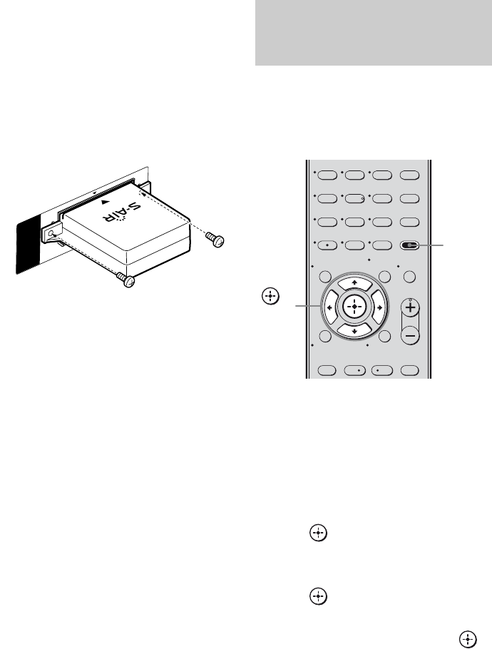
82US
Notes
• Insert the wireless transmitter with the S-AIR logo
facing up.
• Insert the wireless transmitter so that the V marks
are aligned.
• Do not insert other than the wireless transmitter
into the EZW-T100 slot.
3Use the screws that you removed from
step 1 to fasten the wireless
transmitter.
Note
Do not use other screws to fasten the wireless
transmitter.
To insert the wireless
transceiver into the S-AIR sub
unit
For details on installing the wireless
transceiver into surround amplifier and S-AIR
receiver, refer to the operating instructions
supplied with the surround amplifier and
S-AIR receiver.
When you match the ID of the S-AIR main
unit and the S-AIR sub unit, you can establish
sound transmission. You can use multiple
S-AIR main unit by setting a different ID for
each unit.
To set the ID of the S-AIR main
unit
1Press AMP MENU.
“1-LEVEL” appears on the display.
2Press V/v repeatedly to select
“9- S-AIR”.
3Press or b to enter the menu.
4Press V/v repeatedly to select “ID
SETUP”.
5Press or b to enter the parameter.
6Press V/v repeatedly to select the ID
(A, B or C) you want, then press .
To exit the menu
Press AMP MENU.
EZW-T100
Establishing sound transmission
between the S-AIR main unit and
S-AIR sub unit (ID setting)
123
46
78
0/10
ENTER
9
TV CH –
PRESET –
TV CH +
PRESET +
AMP MENU
CLEAR
DISPLAY MUTING
TV VOL
MASTER VOL
DVD/BD
MENU
AUTO CAL
D.TUNING
D.SKIP
THEATER
.<
<
>
5
>10
REPLAY ADVANCE
– CATEGORY +
MEMORY
O
TOOLS/
OPTIONS
RETURN/EXIT
MENU/HOME
AMP
MENU
,
V/v/B/b
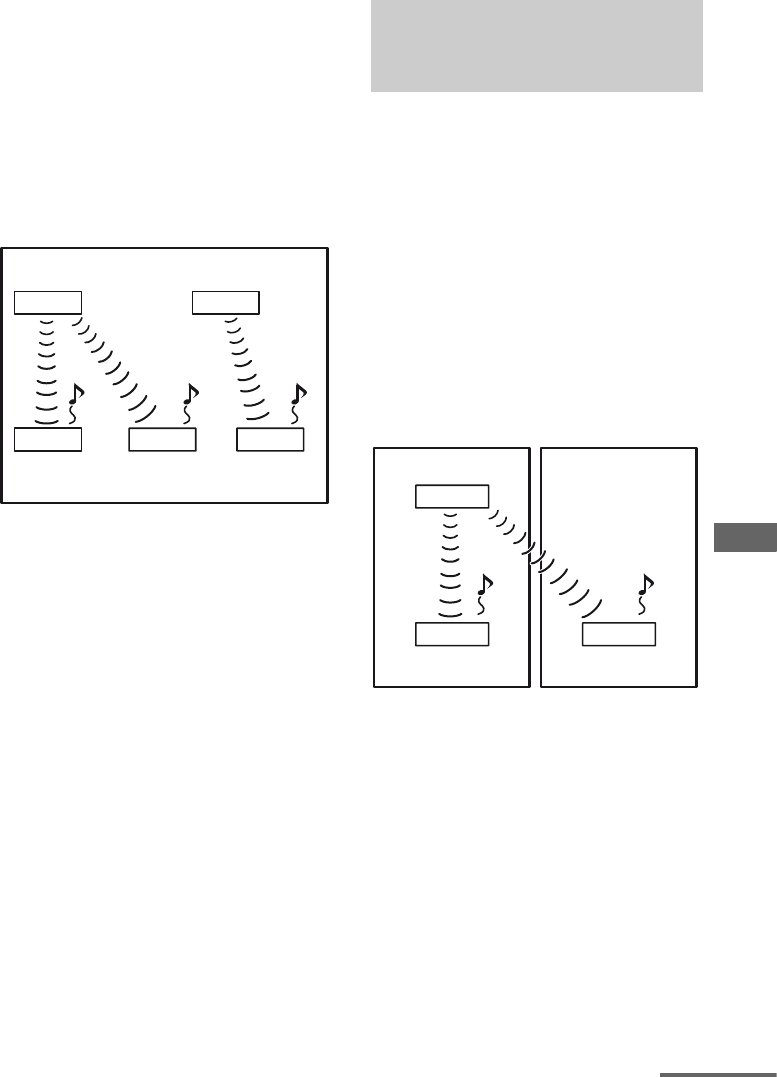
83US
S-AIR Operations
To set the ID of the S-AIR sub
unit
Be sure to match the ID on S-AIR sub unit you
want to the S-AIR main unit.
For details on setting the ID of the surround
amplifier and S-AIR receiver, refer to the
operating instructions supplied with the
surround amplifier and S-AIR receiver.
Sound transmission is established as
follows (example):
Notes
• Sources with copyright protection may not be
playable on S-AIR sub unit.
• When sound transmission is established
– sound can only be output from the S-AIR
receiver if you connect the components to this
receiver via the analog jacks. The sound cannot
be output if the components are connected to the
COAXIAL, OPTICAL or HDMI jacks on this
receiver.
– the headphones function on the surround
amplifier is not available.
To establish sound transmission, you need to
set the same ID for your S-AIR main unit and
S-AIR sub unit.
However, if your neighbors have S-AIR
products and their IDs are the same as yours,
your neighbors could receive the sound of
your S-AIR main unit or vice versa.
To prevent this, you can pair the S-AIR main
unit with a specific S-AIR sub unit by
performing the pairing operation.
xBefore pairing
Sound transmission is established by the ID
(example).
ID A
ID A ID A ID B
ID B
S-AIR main unit
Other S-AIR main
unit
S-AIR sub unit S-AIR sub unit S-AIR sub unit
Pairing the S-AIR main unit with
a specific S-AIR sub unit
(Pairing operation)
ID A
ID A ID A
Your room
S-AIR main unit
S-AIR sub unit S-AIR sub unit
Neighbor
continued
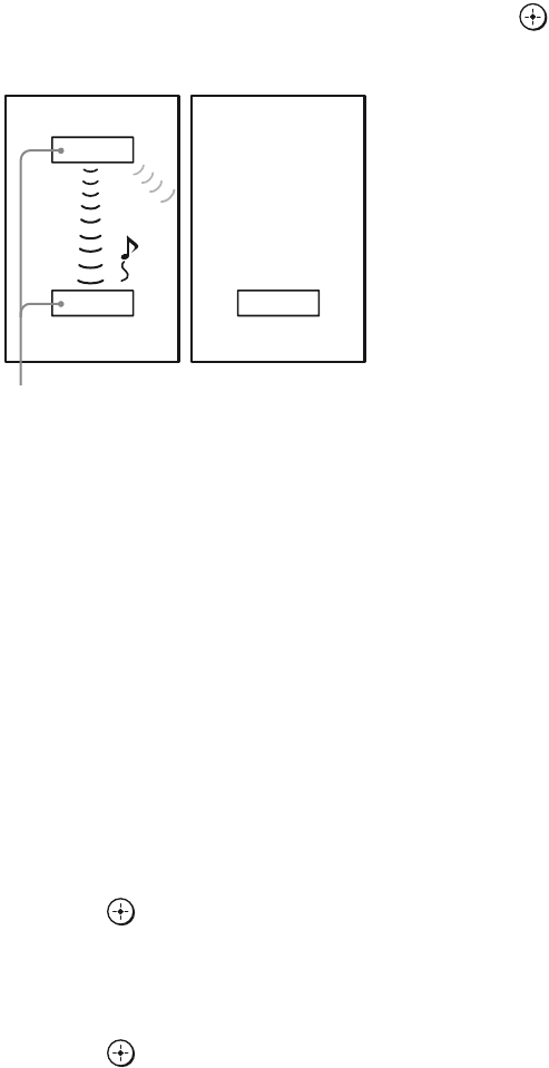
84US
xAfter pairing
Sound transmission is established between the
paired S-AIR main unit and S-AIR sub unit(s)
only.
1Place the S-AIR sub unit that
you want to pair near the S-AIR
main unit.
2Match the IDs of the S-AIR main
unit and the S-AIR sub unit.
• To set the ID of the S-AIR main unit,
see “To set the ID of the S-AIR main
unit” (page 82).
• To set the ID of the S-AIR sub unit,
refer to the operating instructions
supplied with the S-AIR sub unit.
3Press AMP MENU.
“1-LEVEL” appears on the display.
4Press V/v repeatedly to select
“9- S-AIR”.
5Press or b to enter the
menu.
6Press V/v repeatedly to select
“PAIRING”.
7Press or b to enter the
parameter.
8Press V/v repeatedly to select
the setting you want, then
press .
• START: The S-AIR main unit starts
pairing. “SEARCH” flashes on the
display.
• STATUS: You can check the current
ID. When the pairing setting is not
made, “NO PAIR” appears on the
display.
9Start pairing of the S-AIR sub
unit.
xFor the surround amplifier
Refer to the operating instructions
supplied with the surround amplifier.
xFor the S-AIR receiver
Refer to the operating instructions
supplied with the S-AIR receiver.
10Pairing completed.
“COMPLETE” appears on the display.
To exit the menu
Press AMP MENU.
Note
Perform the pairing within several minutes after step
8. Otherwise, the pairing is canceled automatically
and “ERROR” appears on the display.
To cancel pairing
Reset the ID of the S-AIR main unit.
For details, see “To set the ID of the S-AIR
main unit” (page 82). You can select the same
ID as before.
ID A
ID A ID A
You r room
S-AIR main unit
S-AIR sub unit S-AIR sub unit
Neighbor
No transmission
Pairing
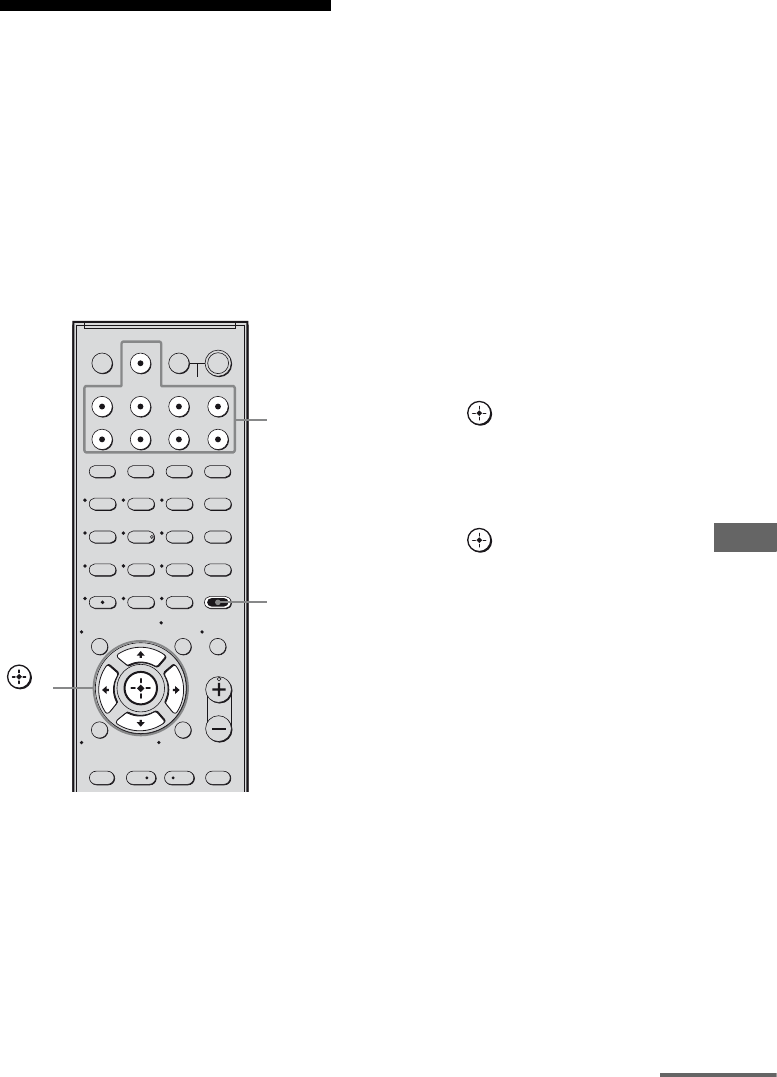
85US
S-AIR Operations
Enjoying the system’s
sound in another room
(For the S-AIR receiver only (not
supplied))
You can enjoy the system’s sound in another
room by using the S-AIR receiver. The S-AIR
receiver can be installed anywhere, regardless
of the location of the S-AIR main unit.
For details of the S-AIR receiver, refer to the
operating instructions supplied with the S-AIR
receiver.
1Set the ID of the S-AIR receiver
to match the ID of the S-AIR
main unit.
• To set the ID of the S-AIR main unit,
see “To set the ID of the S-AIR main
unit” (page 82).
• To set the ID of the S-AIR receiver,
refer to the operating instructions
supplied with the S-AIR receiver.
Notes
• When you are using another S-AIR sub unit,
such as a surround amplifier, do not change
the ID of the S-AIR main unit. Set the ID of
the S-AIR receiver to match the ID of the
S-AIR main unit.
• When you pair the S-AIR main unit and
another S-AIR sub unit, such as a surround
amplifier, you also need to pair the S-AIR
main unit and the S-AIR receiver. For details,
see “Pairing the S-AIR main unit with a
specific S-AIR sub unit (Pairing operation)”
(page 83).
2Press AMP MENU.
“1-LEVEL” appears on the display.
3Press V/v repeatedly to select
“9- S-AIR”.
4Press or b to enter the
menu.
5Press V/v repeatedly to select
“MODE”.
6Press or b to enter the
parameter.
7Press V/v repeatedly to select
the setting you want.
• PARTY: The S-AIR receiver outputs
sound according to the input selected on
the S-AIR main unit. However, if DVD
is selected on S-AIR main unit, S-AIR
receiver remains as the last selected
input.
• SEPARATE: You can select the input
you want for the S-AIR receiver while
the input of the S-AIR main unit remain
unchanged.
Note
When TUNER (FM/AM band) is selected on
the S-AIR main unit, you can only select the
same band for the tuner on the S-AIR
receiver. However, you can select input other
than TUNER on the S-AIR receiver.
123
46
78
0/10
ENTER
9
SYSTEM STANDBY
TV INPUT
SLEEP DMPORT
VIDEO1 VIDEO2 BD DVD
2CH A.F.D.
TV CH –
PRESET –
TV CH +
PRESET +
MOVIE MUSIC
AMP MENU
CLEAR
DISPLAY MUTING
TV VOL
MASTER VOL
DVD/BD
MENU
AUTO CAL
D.TUNING
D.SKIP
THEATER
SAT TV SA-CD/CD TUNER
?/1
.<
<
>
5
>10
REPLAY ADVANCE
– CATEGORY +
MEMORY
O
TV
?/1
AV
?/1
TOOLS/
OPTIONS
RETURN/EXIT
MENU/HOME
AMP
MENU
,
V/v/B/b
Input
buttons
continued
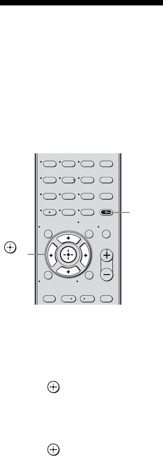
86US
8Adjust the volume on the S-AIR
receiver.
Note
The sound of the S-AIR receiver may be cut off by
operation of the S-AIR main unit.
Changing the channel
for better sound
transmission
If you use multiple wireless systems which
sharing the 2.4 GHz band, such as wireless
LAN or Bluetooth, the transmission of S-AIR
products or other wireless systems may be
unstable. In this case, you may improve the
transmission by changing the “RF SETUP”
setting.
1Press AMP MENU.
“1-LEVEL” appears on the display.
2Press V/v repeatedly to select
“9- S-AIR”.
3Press or b to enter the
menu.
4Press V/v repeatedly to select
“RF SETUP”.
5Press or b to enter the
parameter.
123
46
78
0/10
ENTER
9
TV CH –
PRESET –
TV CH +
PRESET +
AMP MENU
CLEAR
DISPLAY MUTING
TV VOL
MASTER VOL
DVD/BD
MENU
AUTO CAL
D.TUNING
D.SKIP
THEATER
.<
<
>
5
>10
REPLAY ADVANCE
– CATEGORY +
MEMORY
O
TOOLS/
OPTIONS
RETURN/EXIT
MENU/HOME
AMP
MENU
,
V/v/B/b
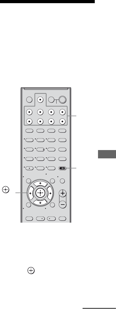
87US
S-AIR Operations
6Press V/v repeatedly to select
the setting you want.
• RF AUTO: Normally select this. The
system changes “RF SETUP” to “RF
ON” or “RF OFF” automatically.
• RF ON: The system transmits sound by
searching the better channel for
transmitting.
• RF OFF: The system transmits sound by
fixing the channel for transmitting.
To exit the menu
Press AMP MENU.
Notes
• When the wireless transmitter is not inserted in the
S-AIR main unit, you cannot set “RF SETUP”.
• In most cases, you will not need to change this
setting.
• If “RF SETUP” is set to “RF OFF,” transmission
between the S-AIR main unit and S-AIR sub unit
can be performed using one of the following
channels.
– S-AIR ID A: equivalent channel for Wi-Fi
channel 1
– S-AIR ID B: equivalent channel for Wi-Fi
channel 6
– S-AIR ID C: equivalent channel for Wi-Fi
channel 11
• The transmission may be improved by changing
the transmission channel (frequency) of the other
wireless system(s). For details, refer to the
operating instructions of the other wireless
system(s).
Enjoying the S-AIR
receiver while the S-AIR
main unit is in standby
mode
(For the S-AIR receiver only (not
supplied))
You can enjoy the S-AIR receiver while the
S-AIR main unit is in standby mode by setting
“STANDBY” to “STBY ON”.
1Press AMP MENU.
“1-LEVEL” appears on the display.
2Press V/v repeatedly to select
“9- S-AIR”.
3Press or b to enter the
menu.
4Press V/v repeatedly to select
“STANDBY”.
123
46
78
0/10
ENTER
9
SYSTEM STANDBY
TV INPUT
SLEEP DMPORT
VIDEO1 VIDEO2 BD DVD
2CH A.F.D.
TV CH –
PRESET –
TV CH +
PRESET +
MOVIE MUSIC
AMP MENU
CLEAR
DISPLAY MUTING
TV VOL
MASTER VOL
DVD/BD
MENU
AUTO CAL
D.TUNING
D.SKIP
THEATER
SAT TV SA-CD/CD TUNER
?/1
.<
<
>
5
>10
REPLAY ADVANCE
– CATEGORY +
MEMORY
O
TV
?/1
AV
?/1
TOOLS/
OPTIONS
RETURN/EXIT
MENU/HOME
AMP
MENU
,
V/v/B/b
Input
buttons
continued

88US
5Press or b to enter the
parameter.
6Press V/v repeatedly to select
the setting you want.
• STBY OFF: You cannot enjoy the
S-AIR receiver while the S-AIR main
unit is in standby mode.
• STBY ON: You can enjoy the S-AIR
receiver while the S-AIR main unit is in
standby mode or turned on.
To exit the menu
Press AMP MENU.
Notes
• When you set “STANDBY” to “STBY ON”, the
power consumption increases during the standby
mode.
• When the wireless transmitter is not inserted in the
S-AIR main unit, you cannot set “STANDBY”.
• When the wireless transmitter is removed from the
S-AIR main unit, “STANDBY” is set to “STBY
OFF” automatically.
• If you have selected TUNER (FM/AM band) on
the S-AIR main unit before you turn it off and
“STANDBY” is set to “STBY ON”, you can only
select the same band for the tuner on the S-AIR
receiver. However, you can select input other than
TUNER on the S-AIR receiver.
• The sound of the S-AIR receiver may be cut off by
operation of the S-AIR main unit.
Switching between
digital and analog audio
(INPUT MODE)
When you connect components to both digital
and analog audio input jacks on the receiver,
you can fix the audio input mode to either of
them, or switch from one to the other,
depending on the type of material you intend
to watch.
1Turn INPUT SELECTOR on the
receiver to select the input.
You can also use the input buttons on the
remote.
2Press INPUT MODE repeatedly
on the receiver to select the
audio input mode.
The selected audio input mode appears on
the display.
Audio input modes
• AUTO
Gives priority to digital audio signals when
there are both digital and analog
connections.
If there are more than one digital connection,
HDMI audio signals have priority over
COAXIAL and OPTICAL audio signals.
If there are no digital audio signals, analog
audio signals are selected.
•COAX
Specifies the digital audio signals input to
the DIGITAL COAXIAL jack.
•OPT
Specifies the digital audio signals input to
the DIGITAL OPTICAL jack.
• ANALOG
Specifies the analog audio signals input to
the AUDIO IN (L/R) jacks.
Other Operations

89US
Other Operations
Notes
• Some audio input modes may not be set up
depending on the input.
• When the ANALOG DIRECT function is being
used, the audio input mode is set to “ANALOG”
automatically. You cannot select other modes.
Listening to digital sound
from other inputs
(DIGITAL ASSIGN)
You can reassign digital audio input that has
OPTICAL or COAXIAL (SAT IN, DVD IN)
signals to another input when they are not
currently being used.
For example, to output the sound source for
the DVD player using the OPTICAL IN jack
on the receiver:
• Connect the optical output jack of the DVD
player to the OPTICAL SAT IN jack of the
receiver.
• Assign “SAT OPT” to “DVD” in the
“D. ASSIGN” setting.
1Press AMP MENU.
“1-LEVEL” appears on the display.
2Press V/v repeatedly to select
“5-AUDIO”.
3Press or b to enter the
menu.
4Press V/v repeatedly to select
“D. ASSIGN”.
5Press or b to enter the
parameter.
6Press V/v repeatedly to select a
vacant digital audio input
(“SAT OPT” in the example).
7Press or b to enter your
selection.
continued

90US
8Press V/v repeatedly to select
the input (“SAT- DVD” in the
example) you want to assign to
the digital audio input jack
selected in step 6.
When “DVD” input is selected, the sound
of the DVD player will become a digital
sound through the OPTICAL SAT IN
jack.
The input you can assign varies for each
audio input. For details, see the following
“Assignable inputs for digital audio
input”.
Assignable inputs for digital
audio input
The initial setting is marked with an
underscore.
Notes
• You cannot reassign more than one digital audio
input to the same input.
• You cannot use the digital audio input as the
original input when it has been reassigned to
another input.
• When you assign the digital audio input, the
INPUT MODE setting may change automatically
(page 88).
Enjoying the DIGITAL
MEDIA PORT
(DMPORT)
The DIGITAL MEDIA PORT (DMPORT)
allows you to enjoy sound and image from a
network system such as a portable audio/video
source or computer.
By connecting a DIGITAL MEDIA PORT
adapter (not supplied), you can enjoy sound
and image from the connected component on
the receiver.
For details, refer to the operating instructions
supplied with the DIGITAL MEDIA PORT
adapter.
Notes
• Do not connect an adapter other than the DIGITAL
MEDIA PORT adapter.
• Before connecting the cords, be sure to disconnect
the AC power cord (mains lead).
• Do not connect or disconnect the DIGITAL
MEDIA PORT adapter while the receiver is turned
on.
• Depending on the DIGITAL MEDIA PORT
adapter, video output may not be possible.
• The DIGITAL MEDIA PORT adapters are
available for purchase depending on the area.
Digital audio
input
[Display]
Assignable
inputs
Display
COAXIAL
DVD IN
[DVD COAX]
VIDEO 1 DVD– VD1
VIDEO 2 DVD– VD2
BD DVD– BD
DVD DVD– DVD
SAT DVD– SAT
SA-CD/CD DVD– CD
OPTICAL
SAT IN
[SAT OPT]
VIDEO 1 SAT– VD1
VIDEO 2 SAT– VD2
BD SAT– BD
DVD SAT– DVD
SAT SAT– SAT
SA-CD/CD SAT– CD
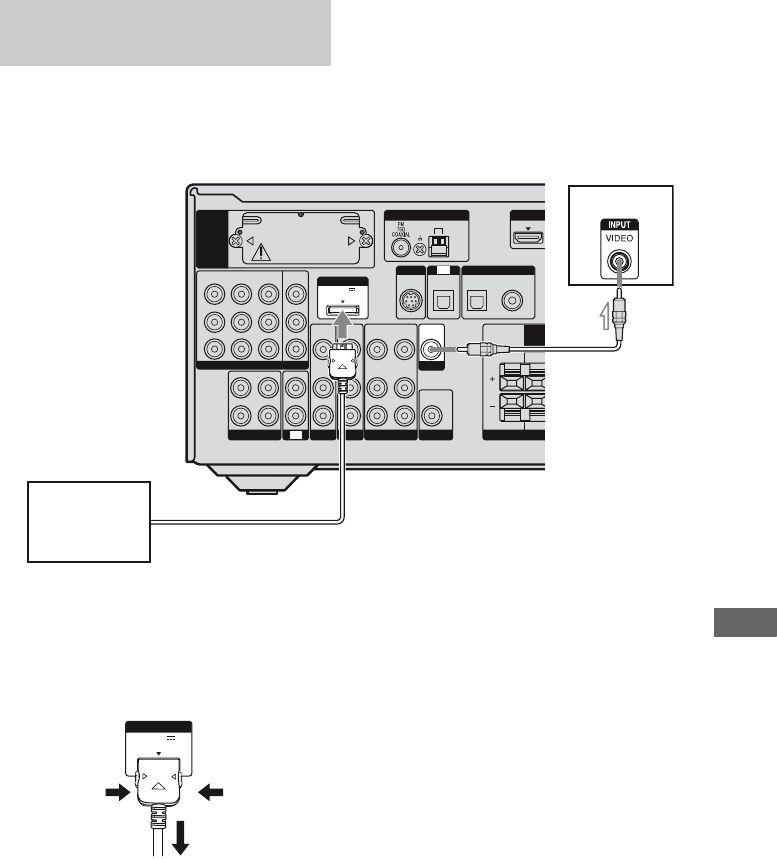
91US
Other Operations
You can listen to the sound and view the
images from the component connected
through the DIGITAL MEDIA PORT adapter
to the DMPORT jack on the receiver.
To detach the DIGITAL MEDIA
PORT adapter from DMPORT
jack
Press and hold both sides of the connector and
then pull out the connector.
Notes
• When connecting the DIGITAL MEDIA PORT
adapter, be sure the connector is inserted with the
arrow mark facing towards the arrow mark on the
DMPORT jack.
• Be sure to make DMPORT connections firmly,
insert the connector straight in.
• As the connector of the DIGITAL MEDIA PORT
adapter is fragile, be sure to handle with care when
placing or moving the receiver.
Connecting the DIGITAL MEDIA
PORT adapter
L
R
DIGITAL
(ASSIGNABLE)
ANTENNA
SIRIUS
SAT IN
SAT
IN
AM
CENTER
R
Y
P
B
/
C
B
COMPONENT VIDEO
OUT IN
P
R
/
C
R
DVD
IN
VIDEO 1
IN
MONITOR
OUT
SA-CD
/
CD
/
CD-R
VIDEO 1
IN
TV
TV
AUDIO
IN
VIDEO
IN
SAT
AUDIO
OUT
AUDIO
OUT
VIDEO
OUT
IN
OPTICAL
AUDIO
IN
VIDEO
IN
SUBWOOFER
AUDIO
IN
VIDEO
IN
BD
SUR
R
F
SAT
IN
DVD
IN
OPTICAL COAXIAL
EZW-T100
VIDEO
OUT
MONITOR
DC5V
0.7A MAX
DMPORT
TV
DIGITAL MEDIA
PORT adapter
AVideo cord (not supplied)
A
DC5V
0.7A MAX
DMPORT
2
1

92US
1Press DMPORT.
You can also use the INPUT SELECTOR
on the receiver to select “DMPORT”.
2Start playback of the connected
component.
The sound is played back on the receiver
and the image appears on the TV.
For details, refer to the operating
instructions supplied with the DIGITAL
MEDIA PORT adapter.
Notes
• Depending on the type of DIGITAL MEDIA
PORT adapter, you can operate the connected
component by using the remote. For details on the
remote button operation, see page 13.
• Be sure you have connected the MONITOR OUT
of the receiver to the TV (page 91).
Tip
When listening to MP3 or other compressed music
using a portable audio source, you can enhance the
sound. Press MUSIC repeatedly to select
“PORTABLE” (page 58).
Changing the display
You can check the sound field, etc., by
changing the information on the display.
Be sure to use the buttons on the receiver for
this operation.
Press DISPLAY repeatedly.
Each time you press the button, the display
changes cyclically as follows.
All inputs except the FM and AM
band and SIRIUS Satellite Radio
Index name of the input* t Selected input t
Sound field currently applied
FM and AM band
Preset station name* t Frequency t Sound
field currently applied
SIRIUS Satellite Radio
Channel name t Channel number t
Category name t Artist name/Feature t
Song/program title t Composer name t
Signal strength t Sound field type
* Index name appears only when you have assigned
one to the input or preset station (page 37, 65).
Index name does not appear when only blank
spaces have been entered, or it is the same as the
input name.
Note
Character or marks may not be displayed for some
languages.
Listening/watching a connected
component through DMPORT
connection

93US
Other Operations
Using the Sleep Timer
You can set the receiver to turn off
automatically at a specified time.
Press SLEEP repeatedly while the
power is on.
Each time you press SLEEP, the display
changes cyclically as follows:
2-00-00 t 1-30-00 t 1-00-00 t 0-30-00
t OFF
When sleep timer is being used, “SLEEP”
lights up in the display.
Tip
To check the remaining time before the receiver
turns off, press SLEEP. The remaining time appears
on the display. If you press SLEEP again, the sleep
timer will be canceled.
Recording using the
receiver
You can record from an audio/video
component using the receiver. Refer to the
operating instructions supplied with your
recording component.
You can record onto a CD-R using the
receiver. Refer to the operating instructions
supplied with your CD recorder.
1Press one of the input buttons
to select the playback
component.
You can also use INPUT SELECTOR on
the receiver.
2Prepare the playback
component for playing.
For example, tune to the radio station you
want to record (page 62).
3Prepare the recording
component.
Insert a blank CD-R into the CD recorder
and adjust the recording level.
4Start recording on the
recording component, then
start playback on the playback
component.
Note
Sound adjustments do not affect the signal output
from the SA-CD/CD/CD-R OUT jacks.
Recording onto a CD-R
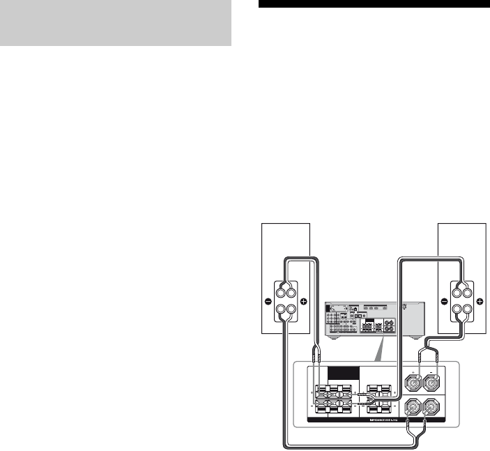
94US
1Press one of the input buttons
to select the playback
component.
You can also use INPUT SELECTOR on
the receiver.
2Prepare the playback
component for playing.
For example, insert the video tape you
want to copy into the VCR.
3Prepare the recording
component.
Insert a blank video tape, etc. into the
recording component (VIDEO 1) for
recording.
4Start recording on the
recording component, then
start playback on the playback
component.
Note
Some sources contain copy guards to prevent
recording. In this case, you may not be able to record
from the source.
Using a bi-amplifier
connection
If you are not using surround back speakers,
you can connect the front speakers to the
SPEAKERS SURROUND BACK/BI-AMP/
FRONT B terminals using a bi-amplifier
connection.
To connect speakers
Connect the jacks on the Lo (or Hi) side of the
front speakers to the SPEAKERS FRONT A
terminals, and connect the jacks on the Hi (or
Lo) side of the front speakers to the
SPEAKERS SURROUND BACK/BI-AMP/
FRONT B terminals.
Make sure that metal fittings of Hi/Lo attached
to the speakers have been removed from the
speakers. Not doing so may cause a
malfunction of the receiver.
Recording onto a recording
media
Hi
Lo
Hi
Lo
SURROUND
L
L
R
R LR
SPEAKERS
SURROUND BACK
/
BI-AMP
/
FRONT B
L
R
DIGITAL
(ASSIGNABLE)
DC5V
0.7A MAX
HDMIANTENNA
DMPORT
SIRIUS
SAT IN
SAT
IN
DVD IN BD IN OUT
AM
Y
P
B
/
C
B
COMPONENT VIDEO
OUT IN
P
R
/
C
R
DVD
IN
VIDEO 1
IN
MONITOR
OUT
SA-CD
/
CD
/
CD-R
VIDEO 1
IN
TV
TV
AUDIO
IN
VIDEO
IN
SAT
AUDIO
OUT
AUDIO
OUT
VIDEO
OUT
VIDEO
OUT
IN
OPTICAL
AUDIO
IN
VIDEO
IN
SUBWOOFER
MONITOR
AUDIO
IN
VIDEO
IN
BD
SAT
IN
DVD
IN
OPTICAL COAXIAL
EZW-T100
CENTER SURROUND
FRONT A
L
L
R
RLR
SPEAKERS
SURROUND BACK
/
BI-AMP
/
FRONT B
CENTER
FRONT A
Front speaker
(R)
Front speaker
(L)
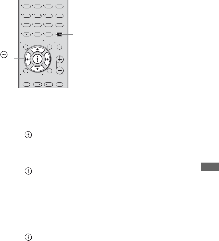
95US
Other Operations
To set up speakers
1Press AMP MENU.
“1-LEVEL” appears on the display.
2Press V/v repeatedly to select
“7-SYSTEM”.
3Press or b to enter the
menu.
4Press V/v repeatedly to select
“SB SPK”.
5Press or b to enter the
parameter.
6Press V/v repeatedly to select
“NO”.
7Press B.
8Press V/v repeatedly to select
“SB ASGN”.
9Press or b to enter the
parameter.
10Press V/v repeatedly to select
“BI-AMP”.
The same signals output from the
SPEAKERS FRONT A terminals can be
output from the SPEAKERS
SURROUND BACK/BI-AMP/FRONT
B terminals.
To exit the menu
Press AMP MENU.
Notes
• Set “SB ASGN” to “BI-AMP” before you perform
auto calibration.
• If you set “SB ASGN” to “BI-AMP”, the speaker
level and distance settings of the surround back
speakers become invalid, and those of the front
speakers are used.
• If SB SPK is set to “SINGLE” or “DUAL”, you
cannot select “SB ASGN”.
123
46
78
0/10
ENTER
9
TV CH –
PRESET –
TV CH +
PRESET +
AMP MENU
CLEAR
DISPLAY MUTING
TV VOL
MASTER VOL
DVD/BD
MENU
AUTO CAL
D.TUNING
D.SKIP
THEATER
.<
<
>
5
>10
REPLAY ADVANCE
– CATEGORY +
MEMORY
O
TOOLS/
OPTIONS
RETURN/EXIT
MENU/HOME
AMP
MENU
,
V/v/B/b

96US
Changing button
assignments
You can change the factory settings of the
input buttons to suit the components in your
system. For example, if you connect a DVD
recorder to the VIDEO 1 jacks on the receiver,
you can set the VIDEO 1 button on this remote
to control the DVD recorder.
Note
You cannot change the settings of DMPORT and
TUNER buttons.
1Hold down the input button of
which you want to change the
assignment.
Example: Hold down VIDEO 1.
2Referring to the table below,
press the corresponding
button for the category you
want.
Example: Press 4.
Now you can use the VIDEO 1 button to
control the DVD recorder.
Categories and the
corresponding buttons
a)Sony VCRs are operated with a VTR 2 or VTR 3
setting which corresponds to 8 mm and VHS
respectively.
b)Sony DVD recorders are operated with a DVD1 or
DVD3 setting. For details, refer to the operating
instructions supplied with the DVD recorders.
c)For details on the BD1 or BD3 setting, refer to the
operating instructions supplied with the Blu-ray
disc player or Blu-ray disc recorder.
To clear all remote button
assignments
While holding down MASTER VOL –, press
?/1 and DMPORT.
The remote is reset to its factory settings.
Using the Remote
Categories Press
VCR (command mode VTR 3)a) 1
VCR (command mode VTR 2)a) 2
DVD player/DVD recorder
(command mode DVD1)b)
3
DVD recorder
(command mode DVD3)b)
4
CD player 5
Euro Digital Satellite Receiver 6
DVR (Digital CATV terminal) 7
DSS (Digital Satellite Receiver) 8
Blu-ray disc player
(command mode BD1)c)
9
Blu-ray disc recorder
(command mode BD3)c)
0/10
TV />10/
CLEAR

97US
Using the Remote/Additional Information
Glossary
xCinema Studio EX
A surround sound mode that can be regarded
as the compilation of Digital Cinema Sound
technology, delivers the sound of a dubbing
theater using three technologies: “Virtual
Multi Dimensions”, “Screen Depth
Matching”, and “Cinema Studio
Reverberation”.
“Virtual Multi Dimensions”, the virtual
speaker technology, creates a virtual multi-
surround environment with actual speakers up
to 7.1 channels, and brings the surround sound
experience of a theater with the latest facilities
into your home.
“Screen Depth Matching” reproduces treble
attenuation, fullness, and depth of sound
usually created in a theater using sound
emission from behind the screen. This is then
added to the front and center channels.
“Cinema Studio Reverberation” reproduces
the sound characteristics of state-of-the-art
dubbing theaters and recording studios,
including Sony Pictures Entertainment’s
dubbing studios. There are three modes, A/B/
C, available according to the studio type.
xComponent video
A format for transmitting video signal
information consisting of three separate
signals: luminance Y, chrominance Pb, and
chrominance Pr. High quality pictures, such as
DVD video or HDTV pictures, are transmitted
more faithfully. The three jacks are color -
coded green, blue and red.
xComposite video
A standard format for transmitting video
signal information. The luminance signal Y
and chrominance signal C are combined and
transmitted together.
xDigital Cinema Sound (DCS)
A unique sound reproduction technology for
home theater developed by Sony, in
cooperation with Sony Pictures Entertainment,
for enjoying the exciting and powerful sound
of movie theaters at home. With this “Digital
Cinema Sound” developed by integrating a
DSP (Digital Signal Processor) and measured
data, the ideal sound field intended by
filmmakers can be experienced at home.
xDolby Digital
Digital audio encoding/decoding technology
developed by Dolby Laboratories, Inc. It
consists of front (left/right), center, surround
(left/right) and subwoofer channels. It is a
designated audio standard for DVD-video and
also known as 5.1 channel surround. Since
surround information is recorded and
reproduced in stereo, more realistic sound with
fuller presence is delivered than with Dolby
surround.
xDolby Digital Surround EX
Acoustic technology developed by Dolby
Laboratories, Inc. Surround back information
is matrixed into regular left and right surround
channels so that the sound can be reproduced
in 6.1 channel. Active scenes, especially, are
recreated with a more dynamic and realistic
sound field.
xDolby Pro Logic II
This technology converts 2 channel stereo
recorded audio into 5.1 channel for playback.
There is a MOVIE mode for movies and
MUSIC mode for stereo sources such as
music. Old movies encoded in the traditional
stereo format can be enhanced with 5.1
channel surround sound.
Additional Information
continued
98US
xDolby Pro Logic IIx
Technology for 7.1 channel (or 6.1 channel)
playback. Along with audio encoded in Dolby
Digital Surround EX, 5.1 channel Dolby
Digital encoded audio can be reproduced in
7.1 channel (or 6.1 channel). Furthermore,
existing stereo recorded content can also be
reproduced in 7.1 channel (or 6.1 channel).
xDolby Surround (Dolby Pro
Logic)
Audio processing technology developed by
Dolby Laboratories, Inc. Center and mono
surround information is matrixed into two
stereo channels. When reproduced, audio is
decoded and output in 4 channel surround
sound. This is the most common audio
processing method for DVD-video.
xDTS 96/24
A high sound quality digital signal format. It
records audio at a sampling frequency and bit
rate of 96kHz/24bit which is the highest
possible for DVD-video. The number of
playback channels varies depending on the
software.
xDTS Digital Surround
Digital audio encoding/decoding technology
for theaters developed by DTS, Inc. It
compresses audio less than Dolby Digital,
delivering a higher quality sound
reproduction.
xDTS-ES
Format for 6.1 channel playback with
surround back information. There are two
modes, “Discrete 6.1” which records all
channels independently, and “Matrix 6.1”
which matrixes surround back channel into LS
(left surround) and RS (right surround)
channels. It is ideal for playback of motion
picture soundtracks.
xDTS Neo:6
This technology converts 2 channel stereo
recorded audio for 6.1 channel playback.
There are two modes to select according to the
playback source or your preference, CINEMA
for movies, and MUSIC for stereo sources
such as music.
xHDMI (High-Definition
Multimedia Interface)
HDMI (High-Definition Multimedia
Interface) is an interface that supports both
video and audio on a single digital connection,
allowing you to enjoy high quality digital
picture and sound. The HDMI specification
supports HDCP (High-bandwidth Digital
Contents Protection), a copy protection
technology that incorporates coding
technology for digital video signals.
xPCM (Pulse Code Modulation)
A method of converting analog audio to digital
audio for easy enjoyment of digital sound.
xS-AIR (Sony Audio Interactive
Radio frequency)
Recent times have seen the rapid spread of
DVD media, Digital Broadcasting, and other
high quality media.
To ensure that the subtle nuances of these high
quality media are transmitted with no
deterioration, Sony has developed a
technology called “S-AIR” for the radio
transmission of digital audio signals with no
compression, and has incorporated this
technology into the EZWRT10/EZW-T100.
This technology transfers digital audio signals
with no compression using the 2.4 GHz band
range of ISM band (Industrial, Scientific, and
Medical band), such as wireless LANs and
Bluetooth applications.

99US
Additional Information
xSampling frequency
To convert analog audio to digital, analog data
should be quantified. This process is called
sampling, and the number of times per second
the analog data is quantified is called the
sampling frequency. A standard music CD
stores data quantified at 44,100 times per
second, which is expressed as a sampling
frequency of 44.1 kHz. Generally speaking, a
higher sampling frequency means better sound
quality.
xx.v.Color
x.v.Color is a more familiar term for the
xvYCC standard proposed by Sony, and is a
trademark of Sony. xvYCC is an international
standard for color space in video.
This standard can express a wider color range
than the currently used broadcast standard.
Precautions
On safety
Should any solid object or liquid fall into the
cabinet, unplug the receiver and have it
checked by qualified personnel before
operating it any further.
On power sources
• Before operating the receiver, check that the
operating voltage is identical with your local
power supply.
The operating voltage is indicated on the
nameplate on the back of the receiver.
• The unit is not disconnected from the AC
power source (mains) as long as it is
connected to the wall outlet, even if the unit
itself has been turned off.
• If you are not going to use the receiver for a
long time, be sure to disconnect the receiver
from the wall outlet. To disconnect the AC
power cord (mains lead), grasp the plug
itself; never pull the cord.
• One blade of the plug is wider than the other
for the purpose of safety and will fit into the
wall outlet only one way. If you are unable to
insert the plug fully into the outlet, contact
your dealer.
• The AC power cord (mains lead) must be
changed only at a qualified service shop.
On heat buildup
Although the receiver heats up during
operation, this is not a malfunction. If you
continuously use this receiver at a large
volume, the cabinet temperature of the top,
side and bottom rises considerably. To avoid
burning yourself, do not touch the cabinet.
continued
100US
On placement
• Place the receiver in a location with adequate
ventilation to prevent heat buildup and
prolong the life of the receiver.
• Do not place the receiver near heat sources,
or in a place subject to direct sunlight,
excessive dust, or mechanical shock.
• Do not place anything on top of the cabinet
that might block the ventilation holes and
cause malfunctions.
• Do not place the receiver near equipment
such as a television, VCR, or tape deck. If
the receiver is being used in combination
with a television, VCR, or tape deck, and is
placed too close to that equipment, noise
may result, and picture quality may suffer.
This is especially likely when using an
indoor antenna (aerial). Therefore, we
recommend using an outdoor antenna
(aerial).
• Use caution when placing the receiver on
surfaces that have been specially treated
(with wax, oil, polish, etc.) as staining or
discoloration of the surface may result.
On operation
Before connecting other components, be sure
to turn off and unplug the receiver.
On cleaning
Clean the cabinet, panel, and controls with a
soft cloth slightly moistened with a mild
detergent solution. Do not use any type of
abrasive pad, scouring powder, or solvent,
such as alcohol or benzine.
If you have any questions or problems
concerning your receiver, please consult your
nearest Sony dealer.
About S-AIR function
• As the S-AIR function transmits sound by
radio waves, sound may skip when radio
waves are obstructed. This is a characteristic
of radio waves and is not malfunction.
• As the S-AIR function transmits sound by
radio waves, equipment that generates
electromagnetic energy, such as a
microwave oven, may interfere with sound
transmission.
• As the S-AIR function uses the radio waves
that share the same frequency as other
wireless systems, such as wireless LAN or
Bluetooth, interference or poor transmission
may result. In this case, take the following
steps:
– Do not install the system near other
wireless systems.
– Do not use the system and the other
wireless systems at the same time.
• The transmission distance differs depending
on the usage environment. Find a location
where transmission between the S-AIR main
unit and sub unit is most effective, and
install the S-AIR main unit and sub unit
there.

101US
Additional Information
Troubleshooting
If you experience any of the following
difficulties while using the receiver, use this
troubleshooting guide to help you remedy the
problem.
There is no sound, no matter which
component is selected, or only a very
low-level sound is heard.
• Check that the speakers and components
are connected correctly and securely.
• Check that all speaker cords are connected
correctly.
• Check that both the receiver and all
components are turned on.
• Check that MASTER VOLUME is not set
to “VOL MIN”.
• Check that the SPEAKERS is not set to
OFF (page 30).
• Check that headphones are not connected.
• Press MUTING to cancel the muting
function.
• Check that you have selected the correct
component with the input buttons.
• The protective device on the receiver has
been activated. Turn off the receiver,
eliminate the short-circuit problem, and
turn on the power again.
There is no sound from a specific
component.
• Check that the component is connected
correctly to the audio input jacks for that
component.
• Check that the cord(s) used for the
connection is (are) fully inserted into the
jacks on both the receiver and the
component.
There is no sound from one of the front
speakers.
• Connect a pair of headphones to the
PHONES jack to verify that sound is
output from the headphones. If only one
channel is output from the headphones, the
component may not be connected to the
receiver correctly. Check that all the cords
are fully inserted into the jacks on both the
receiver and the component. If both
channels are output from the headphones,
the front speaker may not be connected to
the receiver correctly. Check the
connection of the front speaker which is
not outputting any sound.
• Make sure you have connected to both the
L and R jacks of an analog component, and
not only to either the L or R jack. Use an
audio cord (not supplied).
There is no sound from digital sources
(from COAXIAL or OPTICAL input jack).
• Check that the INPUT MODE is not set to
“ANALOG” (page 88).
• Check that ANALOG DIRECT is not set
to on.
• Check to make sure the selected digital
audio input jack is not assigned to other
inputs using DIGITAL ASSIGN function
(page 89).
The left and right sounds are
unbalanced or reversed.
• Check that the speakers and components
are connected correctly and securely.
• Adjust the balance parameters using the
LEVEL menu.
“NO INPUT” appears on the display
• Check that your component is connected
to the COAXIAL or OPTICAL jack. If no
signal is input through the COAXIAL or
OPTICAL jack, “NO INPUT” appears on
the display and this is not a malfunction.
Audio
continued

102US
There is severe hum or noise.
• Check that the speakers and components
are connected securely.
• Check that the connecting cords are away
from a transformer or motor, and at least
10 feet (3 meters) away from a TV set or
fluorescent light.
• Move your audio components away from
the TV.
• The plugs and jacks are dirty. Wipe them
with a cloth slightly moistened with
alcohol.
There is no sound, or only a very low-
level sound is heard from the center/
surround/surround back speakers.
• Select a CINEMA STUDIO EX mode
(page 59).
• Adjust the speaker level (page 35).
• Make sure the center/surround speakers
are set to either “SMALL” or “LARGE”
(page 43).
• Make sure the surround back speakers are
set to “SINGLE” or “DUAL” (page 43).
There is no sound from the surround
back speaker.
• Some discs have no Dolby Digital
Surround EX flag even though the
packages have Dolby Digital Surround EX
logos. In this case, select “SB ON” (page
41).
There is no sound from the subwoofer.
• Check that the subwoofer is connected
correctly and securely.
• Make sure you have turned on your
subwoofer.
• Make sure the subwoofer is set to “YES”
(page 43).
• There is no sound from the subwoofer
depending on the sound field.
The surround effect cannot be
obtained.
• Make sure the sound field function is on
(press MOVIE, or MUSIC).
• Sound fields do not function for signals
with a sampling frequency of more than
48 kHz.
Dolby Digital or DTS multi channel
sound is not reproduced.
• Check that the DVD, etc. you are playing
is recorded in Dolby Digital or DTS
format.
• When connecting the DVD player, etc., to
the digital input jacks of this receiver,
check the audio setting (the settings for the
audio output) of the connected component.
There is no sound from the component
connected to the DIGITAL MEDIA PORT
adapter.
• Adjust the volume of this receiver.
• The DIGITAL MEDIA PORT adapter
and/or component is not connected
correctly. Turn off the receiver, then
reconnect the DIGITAL MEDIA PORT
adapter and/or component.
• Check the DIGITAL MEDIA PORT
adapter and/or component device to make
sure it supports this receiver.

103US
Additional Information
There is no picture or an unclear
picture appears on the TV screen.
• Select the appropriate input using the input
buttons.
• Set your TV to the appropriate input mode.
• Move your audio components away from
the TV.
• Depending on the DIGITAL MEDIA
PORT adapter, video output may not be
possible.
Recording cannot be carried out.
• Check that the components are connected
correctly (page 22).
• Select the source component using the
input buttons (page 36).
The source sound input to the HDMI
jack on the receiver is not output from
the receiver or the TV speaker.
• Check the HDMI connection.
• You cannot listen to the Super Audio CD
by connecting HDMI.
• Depending on the playback component,
you may need to set up the component.
Refer to the operating instructions
supplied with each component.
The source image input to the HDMI
jack on the receiver is not output from
the TV.
• Check the HDMI connection.
• Depending on the playback component,
you may need to set up the component.
Refer to the operating instructions
supplied with each component.
The control for HDMI function does not
work.
• Check the HDMI connection (page 23).
• Make sure “CONTROL FOR HDMI” is
set to “CTRL ON” in HDMI menu.
• Make sure the connected component is
compatible with the Control for HDMI
function.
• Check the Control for HDMI settings on
the connected component. See the
operating instructions of the connected
component.
• If you change the HDMI connection,
connect/disconnect the AC power cord, or
there is a power failure, repeat the
procedures of “Preparing for the
“BRAVIA” Sync” (page 76).
No sound is output from the receiver
and TV speaker while using the System
Audio Control function.
• Make sure the TV is compatible with the
System Audio Control function.
• If the TV does not have System Audio
Control function, set the “AUDIO FOR
HDMI” settings in HDMI menu to
– “TV+AMP” if you want to listen to the
sound from the TV speaker and
receiver.
– “AMP” if you want to listen to the
sound from the receiver.
• If you cannot listen to the sound of a
component connected to the receiver
– Select the appropriate input when you
want to watch a program on a
component connected via HDMI
connection to the receiver.
– Change the TV channel when you want
to watch a TV broadcast.
– Select the component or input you want
to watch when you watch a program on
the component connected to the TV.
Refer to the operating instructions of the
TV on this operation.
Video
HDMI
continued

104US
The TV’s remote cannot be used to
control the connected component
when using the Control for HDMI
function.
• Change the input of the receiver to the
HDMI input connected to the component.
Sound transmission is not established.
• If you use another S-AIR main unit, place
it more than 26 1/4 feet (8 m) away from
this S-AIR main unit.
• Confirm the ID of the S-AIR main unit and
S-AIR sub unit (page 82).
• You performed pairing the S-AIR main
unit and another S-AIR sub unit.
Perform pairing of the desired S-AIR sub
unit (page 83).
• The S-AIR main unit is pairing with
another S-AIR sub unit. Cancel pairing.
• Install the S-AIR main unit and S-AIR sub
unit away from other wireless products.
• Stop using another wireless product.
• The S-AIR sub unit is turned off. Make
sure the AC power cord (mains lead) is
connected and turn on the S-AIR sub unit.
No sound is heard from the S-AIR
receiver.
• Check that the components are connected
to analog jack of this receiver.
No sound is heard from the S-AIR
product.
• If you use another S-AIR main unit, place
it more than 26 1/4 feet (8 m) away from
this S-AIR main unit.
• Confirm the ID of the S-AIR main unit and
S-AIR sub unit (page 82).
• Confirm the pairing setting (page 83).
• Install the S-AIR main unit and S-AIR sub
unit closer together.
• Avoid use of equipment that generates
electromagnetic energy, such as a
microwave oven.
• Install the S-AIR main unit and S-AIR sub
unit away from other wireless products.
• Stop using another wireless product.
• Change the “RF SETUP” setting (page
86).
• Change the ID settings of the S-AIR main
unit and S-AIR sub unit.
• Turn off the system and S-AIR sub unit,
then turn on them.
• Check that headphones are not connected
to the S-AIR sub unit.
There is noise or the sound skips.
• If you use another S-AIR main unit, place
it more than 26 1/4 feet (8 m) away from
this S-AIR main unit.
• Install the S-AIR main unit and S-AIR sub
unit closer together.
• Avoid use of equipment that generates
electromagnetic energy, such as a
microwave oven.
• Install the S-AIR main unit and S-AIR sub
unit away from other wireless products.
• Stop using another wireless product.
• Change the “RF SETUP” setting (page
86).
• Change the ID settings of the S-AIR main
unit and S-AIR sub unit.
S-AIR function
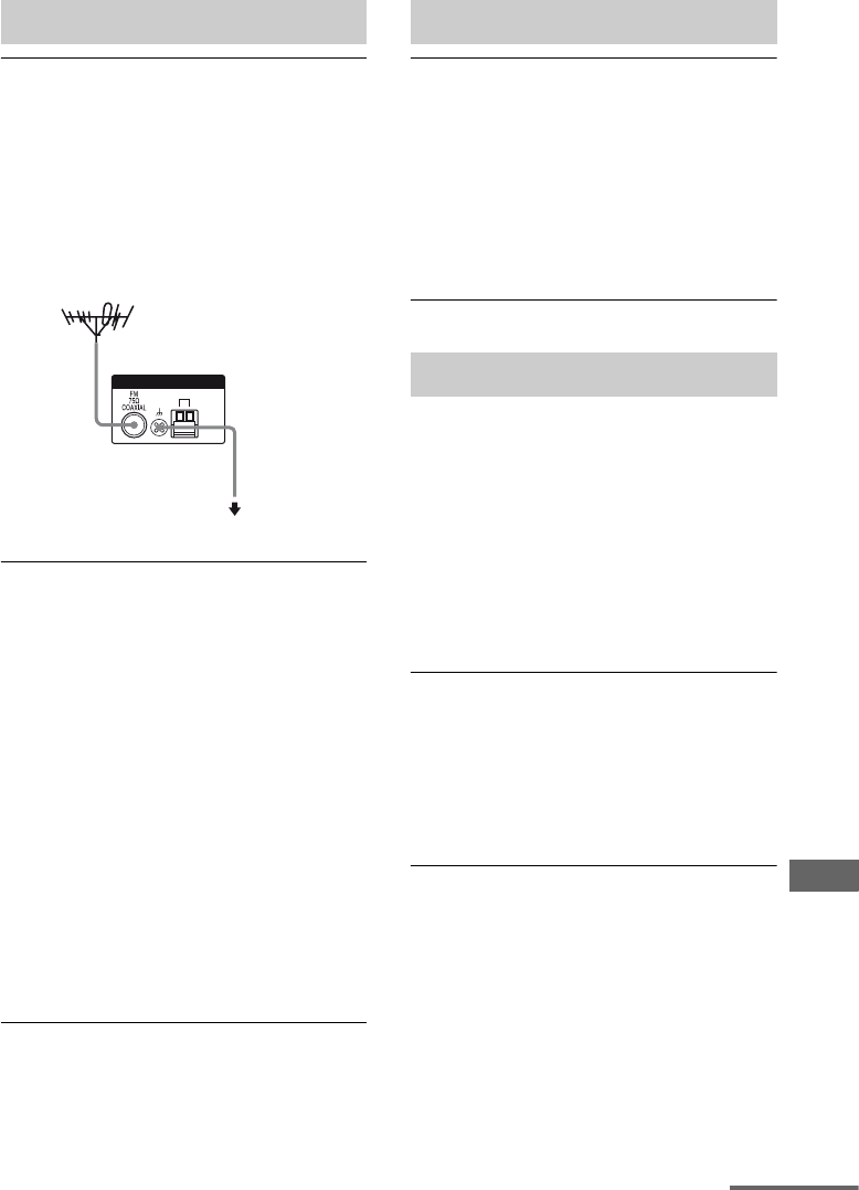
105US
Additional Information
The FM reception is poor.
• Use a 75-ohm coaxial cable (not supplied)
to connect the receiver to an outdoor FM
antenna (aerial) as shown below. If you
connect the receiver to an outdoor antenna
(aerial), ground it against lightning. To
prevent a gas explosion, do not connect the
ground wire to a gas pipe.
Radio stations cannot be tuned in.
• Check that the antennas (aerials) are
connected securely. Adjust the antennas
(aerials) and connect an external antenna
(aerial), if necessary.
• The signal strength of the stations is too
weak (when tuning in with automatic
tuning). Use direct tuning.
• Make sure you set the tuning interval
correctly (when tuning in AM stations
with direct tuning).
• No stations have been preset or the preset
stations have been cleared (when tuning by
scanning preset stations). Preset the
stations (page 64).
• Press DISPLAY repeatedly on the receiver
so that the frequency appears on the
display.
The remote does not function.
• Point the remote at the remote sensor on
the receiver.
• Remove any obstacles in the path between
the remote and the receiver.
• Replace all the batteries in the remote with
new ones, if they are weak.
• Make sure you select the correct input on
the remote.
If there is a malfunction, the display shows a
message. You can check the condition of the
system by the message. Refer to the following
table to solve the problem. If any problem
persists, consult your nearest Sony dealer.
If an error message appears while you perform
Auto Calibration, see “Error and warning
codes” (page 33) to solve the problem.
For other message, see “SIRIUS Satellite
Radio message list” (page 74).
PROTECT
Irregular current is output to the speakers, or
the upper panel of the receiver is covered
with something. The receiver will
automatically turn off after a few seconds.
Check the speaker connection and turn on
the power again.
Tuner
ANTENNA
AM
Receiver
To ground
Ground wire
(not supplied)
Outdoor FM antenna (aerial)
Remote commander
Error messages
continued

106US
Clearing the receiver’s memory may remedy
the problem (page 29). However, note that all
memorized settings will be reset to their initial
settings and you will have to readjust all
settings on the receiver.
Consult your nearest Sony dealer. Note that if
service personnel changes some parts during
repair, these parts may be retained.
In the event of a problem with S-AIR function,
have a Sony dealer check the entire system
together (S-AIR main unit and S-AIR sub
unit).
Specifications
AUDIO POWER
SPECIFICATIONS
POWER OUTPUT AND TOTAL
HARMONIC DISTORTION:
(Models of area code U only)
With 8 ohm loads, both channels driven, from
20 – 20,000 Hz; rated 95 watts per channel
minimum RMS power, with no more than
0.09% total harmonic distortion from 250
milliwatts to rated output.
Amplifier section
Models of area code U, CA1)
Minimum RMS Output Power (8 ohms, 20 Hz –
20 kHz, THD 0.09%)
95 W + 95 W
Stereo Mode Output Power (8 ohms, 1 kHz,
THD 1%)
105 W + 105 W
Surround Mode Output Power2) (8 ohms, 1 kHz,
THD 10%)
140 W/ch
1)Measured under the following conditions:
2)Reference power output for front, center, surround
and surround back speakers. Depending on the
sound field settings and the source, there may be
no sound output.
Frequency response
Analog 10 Hz – 70 kHz
+0.5/–2 dB (with sound
field and equalizer
bypassed)
If you are unable to remedy the
problem using the
troubleshooting guide
If the problem persist
Reference sections for clearing
the receiver’s memory
To clear See
All memorized settings page 29
Customized sound fields page 61
Area code Power requirements
U, CA 120 V AC, 60 Hz

107US
Additional Information
Inputs
Analog Sensitivity: 500 mV/
50 kohms
S/N3): 96 dB
(A, 500 mV4))
Digital (Coaxial) Impedance: 75 ohms
S/N: 100 dB
(A, 20 kHz LPF)
Digital (Optical) S/N: 100 dB
(A, 20 kHz LPF)
Outputs (Analog)
AUDIO OUT Voltage: 500 mV/
10 kohms
SUBWOOFER Voltage: 2 V/1 kohm
Equalizer
Gain levels ±6 dB, 1 dB step
3)INPUT SHORT (with sound field and equalizer
bypassed).
4)Weighted network, input level.
FM tuner section
Tuning range 87.5 – 108.0 MHz
Antenna FM wire antenna
Antenna terminals 75 ohms, unbalanced
Intermediate frequency
10.7 MHz
AM tuner section
Tuning range
Antenna Loop antenna
Intermediate frequency
450 kHz
Video section
Inputs/Outputs
Video: 1 Vp-p/75 ohms
COMPONENT VIDEO:
Y: 1 Vp-p/75 ohms
PB/CB: 0.7 Vp-p/75 ohms
PR/CR: 0.7 Vp-p/75 ohms
80 MHz HD Pass Through
General
Power requirements
Power output (DIGITAL MEDIA PORT)
DC OUT: 5 V, 0.7 A MAX
Power consumption
Power consumption (during standby mode)
0.3 W (when “CONTROL
FOR HDMI” in HDMI
menu is set to “CTRL
OFF” and “STANDBY” in
S-AIR menu is set to
“STBY OFF”)
Dimensions (w/h/d) (Approx.)
17 × 6 1/4 × 12 3/4 inches
(430 × 157.5 × 322 mm)
including projecting parts
and controls
Mass (Approx.) 17 lb 11 oz (8.0 kg)
Supplied accessories
Operating instructions (this manual)
Quick Setup Guide (1)
FM wire antenna (aerial) (1)
AM loop antenna (aerial) (1)
RM-AAU021 Remote Commander (1)
R6 (size-AA) batteries (2)
Optimizer microphone (ECM-AC2 or
ECM-AC2a) (1)
Design and specifications are subject to
change without notice.
Area code Tuning scale
10 kHz step 9 kHz step
U, CA 530 –
1,710 kHz
531 –
1,710 kHz
Area code Power requirements
U, CA 120 V AC, 60 Hz
Area code Power consumption
U, CA 240 W
For details on the area code of the
component you are using, see page 4.
Halogenated flame retardants are not used in
the certain printed wiring boards.

Sony Corporation Printed in Malaysia
Index
Numerics
2 channel 60
2CH STEREO 60
5.1 channel 17
7.1 channel 17
A
AUTO CALIBRATION 31
AUTO FORMAT DIRECT
(A.F.D.) 56
B
BI-AMP 53
Bi-amplifier connection 94
Blu-ray disc player
connecting 23, 25
playback 39
C
Camcorder
connecting 27
CD player
connecting 21
playback 38
CD recorder
connecting 21
D
DIGITAL ASSIGN 89
Digital Cinema Sound
(DCS) 97
DIGITAL MEDIA PORT
connecting 91
Dolby Digital 97
DTS 98
DVD player
connecting 25
playback 39
DVD recorder
connecting 27
E
Error messages 105
H
HDMI
Audio for HDMI 50
connecting 23
Control for HDMI 51
I
Initial setup 29
INPUT MODE 88
M
Menu
A. CAL 55
AUDIO 49
EQ 46
HDMI 50
LEVEL 45
S. AIR 56
SUR 46
SYSTEM 51
TUNER 48
Muting 36
N
Naming 37, 65
O
One-Touch Play 77
P
PAIRING 83
Parental Lock 42, 72
R
Recording
onto a CD-R 93
onto a recording media
94
Remote commander 13
S
S-AIR 80
Satellite tuner
connecting 26
SB DEC 47
Selecting
component 36
sound field 58
speaker system 30
Set-top box
connecting 26
SIRIUS Satellite Radio 66
Sleep Timer 93
Sound fields
resetting 61
selecting 58
Speakers
connecting 18
Super Audio CD player
connecting 21
playback 38
System Audio Control 78
System Power Off 79
T
TEST TONE 35
Tuner
connecting 28
Tuning
automatically 62
directly 63
to preset stations 65
TV
connecting 20
V
VCR
connecting 27
Video game
connecting 27
(3)
