Sony 5500 Users Manual SRW 5000/5500
5500 to the manual 8ca24c96-41a9-4eca-8bc7-374482da2fbf
2015-01-24
: Sony Sony-5500-Users-Manual-288272 sony-5500-users-manual-288272 sony pdf
Open the PDF directly: View PDF ![]() .
.
Page Count: 187 [warning: Documents this large are best viewed by clicking the View PDF Link!]
- Table of Contents
- Chapter 1 Overview
- Chapter 2 Locations and Functions of Parts
- Chapter 3 Setting Up the VTR
- Chapter 4 Menu Settings
- 4-1 Registering and Storing Menu Settings
- 4-1-1 Menu Configuration
- 4-1-2 Changing Menu Settings
- 4-1-3 Registering Items to the VTR SETUP Menu
- 4-1-4 VTR Memory Bank Function
- 4-1-5 Memory Stick Operations
- 4-1-6 Adding Titles to the Data
- 4-1-7 Details on VTR Memory Bank and Memory Stick Functions
- 4-1-8 Memory Stick Data Compatibility
- 4-1-9 Automatic Reading from a VTR Bank at Power On
- 4-1-10 Saving and Recalling DEFAULT Settings on a Bank
- 4-1-11 Saving and Recalling DEFAULT Settings in a “Memory Stick”
- 4-2 HOME Menu
- 4-2-1 Selecting the Output Signals (PB/EE)
- 4-2-2 Record Inhibit Mode (REC INH)
- 4-2-3 Selecting the Edit Mode and Edit Channel (ASSEMBLE, INS TC, INS VIDEO, INS AUDIO and INS CUE)
- 4-2-4 Preread Settings (PRE READ)
- 4-2-5 Still-Picture Output (FREEZE)
- 4-2-6 Setting the Preroll Time (PREROLL TIME)
- 4-2-7 Selecting DMC Playback (DMC)
- 4-2-8 Setting the Stop Code (STOP CODE)
- 4-3 TC Menu
- 4-3-1 Setting the Time Data (TIMER SEL/RESET/SET/HOLD)
- 4-3-2 Setting the Time Code Reader (TCR SEL)
- 4-3-3 Setting the Time Code Generator (TCG SOURCE/MODE)
- 4-3-4 Selecting the Time Code Running Mode (RUN MODE)
- 4-3-5 Selecting the Drop Frame Mode (DF/NDF)
- 4-3-6 Selecting the Content of the Second Time Code Display Area (TC2 SEL)
- 4-3-7 Selecting CTL Display Mode (TAPE TIMER)
- 4-3-8 Presetting Pulldown Time Code (PDPSET MENU) (when HKSR-5001 is installed)
- 4-3-9 Presetting for Conversion from Frame Time Code (TCCONV MENU)
- 4-3-10 Displaying the Pulldown Time Code (PDTC DISP) (when HKSR-5001 is installed)
- 4-3-11 Superimposition of Character Information (PD CHARA/CHARA SUPER/H-POS/V-POS)
- 4-4 CUE Menu
- 4-5 VIDEO Menu
- 4-6 AUDIO Menu
- 4-6-1 Selecting the Audio Input Signal (AUDIO IN)
- 4-6-2 Digital Audio Output Signal Source Track Selection (DIGOUT EXCHNG)
- 4-6-3 Analog Audio Output Signal Source Track Selection (ANAOUT EXCHNG)
- 4-6-4 Digital Audio Output Signal Source Track Selection (SDOUT EXCHNG)
- 4-6-5 Audio Transition Type Selection for Digital Audio Editing (AUDIO EDIT)
- 4-6-6 Fade Processing Time Selection for Digital Audio Editing (FADE TIME)
- 4-6-7 External Device Digital Audio Edit Preset Command Replace Mode Selection (AUDIO EDIT PRESET REPLACE)
- 4-6-8 External Device Analog Audio Edit Preset Command Replace Mode Selection (ANALOG AUDIO EDIT REPLACE)
- 4-6-9 PITCH GROUP Selection (PITCH CORRECTION GROUP SELECT)
- 4-7 SET UP Menu
- 4-1 Registering and Storing Menu Settings
- Chapter 5 Recording/Playback
- Chapter 6 Editing
- Appendix
- Maintenance
- Specifications
- Error Messages and Warning Messages
- Glossary
- Menu List
- Items Relating to VTR Operations (Nos. 001 to ...)
- Items Relating to Operation Panels (Nos. 101 to ...)
- Items Relating to Remote Interface (Nos. 201 to ...)
- Items Relating to Editing (Nos. 301 to ...)
- Items Relating to Prerolling (Nos. 401 to ...)
- Items Relating to Recording Protection (Nos. 501 to ...)
- Items Relating to the Time Code (Nos. 601 to ...)
- Items Relating to the Video Control (Nos. 706 to ...)
- Items Relating to the Audio Control (Nos. 807 to ...)
- Items Relating to Digital Processing (Nos. 902 to ...)
- Items Relating to the Pulldown Control (Nos. A01 to ...)
- Other Items (Nos. T01 to ...)
- Index

HD DIGITAL VIDEOCASSETTE RECORDER
SRW-5000
SRW-5500
FORMAT CONVERTER BOARD
HKSR-5001
DIGITAL BETACAM PROCESSOR BOARD
HKSR-5002
RGB PROCESSOR BOARD
HKSR-5003
OPERATION MANUAL [English]
1st Edition (Revised 4)
2
• Read these instructions.
• Keep these instructions.
• Heed all warnings.
• Follow all instructions.
• Do not use this apparatus near water.
• Clean only with dry cloth.
• Do not block any ventilation openings.
Install in accordance with the manufacturer’s
instructions.
• Do not install near any heat sources such as radiators,
heat registers, stoves, or other apparatus (including
amplifiers) that produce heat.
• Do not defeat the safety purpose of the polarized or
grounding-type plug. A polarized plug has two blades
with one wider than the other. A grounding-type plug
has two blades and a third grounding prong. The wide
blade or the third prong are provided for your safety. If
the provided plug does not fit into your outlet, consult an
electrician for replacement of the obsolete outlet.
• Protect the power cord from being walked on or pinched
particularly at plugs, convenience receptacles, and the
point where they exit from the apparatus.
• Only use attachments/accessories specified by the
manufacturer.
• Use only with the cart, stand, tripod, bracket,
or table specified by the manufacturer, or sold
with the apparatus.
When a cart is used, use caution when moving
the cart/apparatus combination to avoid injury from tip-
over.
• Unplug this apparatus during lightning storms or when
unused for long periods of time.
• Refer all servicing to qualified service personnel.
Servicing is required when the apparatus has been
damaged in any way, such as power-supply cord or plug
is damaged, liquid has been spilled or objects have fallen
into the apparatus, the apparatus has been exposed to
rain or moisture, does not operate normally, or has been
dropped.
To prevent fire or shock hazard, do not
expose the unit to rain or moisture.
To avoid electrical shock, do not open the
cabinet. Refer servicing to qualified
personnel only.
THIS APPARATUS MUST BE EARTHED.
WARNING: THIS WARNING IS APPLICABLE
FOR USA ONLY.
If used in USA, use the UL LISTED power
cord specified below.
DO NOT USE ANY OTHER POWER
CORD.
Plug Cap Parallel Blade with ground pin
(NEMA 5-15P Configuration)
Cord Type SJT, three 16 or 18 AWG
wires
Length Minimum 1.5 m (4 ft 11 in), less
than 2.5 m (8 ft 3 in)
Rating Minimum 10 A, 125 V
Using this unit at a voltage other than 120 V
may require the use of a different line cord
or attachment plug, or both. To reduce the
risk of fire or electric shock, refer servicing
to qualified service personnel.
WARNING: THIS WARNING IS APPLICABLE
FOR OTHER COUNTRIES.
1. Use the approved Power Cord (3-core mains lead)/
Appliance Connector/Plug with earthing-contacts that
conforms to the safety regulations of each country if
applicable.
2. Use the Power Cord (3-core mains lead)/Appliance
Connector/Plug conforming to the proper ratings
(Voltage, Ampere).
Important Safety Instructions
WARNING
This symbol is intended to alert the user to
the presence of uninsulated “dangerous
voltage” within the product’s enclosure
that may be of sufficient magnitude to
constitute a risk of electric shock to
persons.
This symbol is intended to alert the user to
the presence of important operating and
maintenance (servicing) instructions in
the literature accompanying the
appliance.

3
If you have questions on the use of the above Power Cord/
Appliance Connector/Plug, please consult a qualified
service personnel.
CAUTION
The apparatus shall not be exposed to dripping or
splashing and no objects filled with liquid, such as vases,
shall be placed on the apparatus.
CAUTION
The unit is not disconnected from the AC power source
(mains) as long as it is connected to the wall outlet, even if
the unit itself has been turned off.
For the customers in U.S.A.
This equipment has been tested and found to comply with
the limits for a Class A digital device, pursuant to Part 15
of the FCC Rules. These limits are designed to provide
reasonable protection against harmful interference when
the equipment is operated in a commercial environment.
This equipment generates, uses, and can radiate radio
frequency energy and, if not installed and used in
accordance with the instruction manual, may cause
harmful interference to radio communications. Operation
of this equipment in a residential area is likely to cause
harmful interference in which case the user will be
required to correct the interference at his own expense.
You are cautioned that any changes or modifications not
expressly approved in this manual could void your
authority to operate this equipment.
The shielded interface cable recommended in this manual
must be used with this equipment in order to comply with
the limits for a digital device pursuant to Subpart B of Part
15 of FCC Rules.
For the customers in the U.S.A.
This product contains mercury. Disposal of this product
may be regulated if sold in the U.S.A. For disposal or
recycling information, please contact your local authorities
or the Electronics Industries Alliance
(www.eiae.org http://www.eiae.org ).
Do not install the appliance in a confined space, such as
book case or built-in cabinet.
For the customers in Europe
This product with the CE marking complies with both the
EMC Directive (89/336/EEC) and the Low Voltage
Directive (73/23/EEC) issued by the Commission of the
European Community.
Compliance with these directives implies conformity to
the following European standards:
• EN60065: Product Safety (For SRW-5000/5500)
• EN55103-1: Electromagnetic Interference (Emission)
• EN55103-2: Electromagnetic Susceptibility (Immunity)
This product is intended for use in the following
Electromagnetic Environment(s):
E1 (residential), E2 (commercial and light industrial), E3
(urban outdoors), E4 (controlled EMC environment, ex.
TV studio).

4Table of Contets
Table of Contents
Chapter 1 Overview
1-1 Features ........................................................................... 9
1-1-1 Features of the SRW-5000/SRW-5500.............................9
1-1-2 Features of the Control Panel..........................................11
1-2 Optional Accessories ................................................... 13
1-3 Using the CD-ROM Manual .......................................... 13
1-3-1 CD-ROM System Requirements.....................................13
1-3-2 Preparations.....................................................................13
1-3-3 To Read the CD-ROM Manual.......................................13
Chapter 2 Locations and Functions of Parts
2-1 Control Panel................................................................. 15
2-1-1 Upper Control Panel .......................................................16
2-1-2 Lower Control Panel .......................................................17
2-1-3 System Set-Up Panel.......................................................23
2-2 Connector Panel ........................................................... 24
Chapter 3 Setting Up the VTR
3-1 Connecting External Equipment ................................. 29
3-1-1 Making HD Digital Connections ....................................29
3-1-2 Making NTSC/PAL Digital Connections .......................30
3-1-3 Cascade Connection........................................................31
3-2 Reference Signals......................................................... 32
3-2-1 Reference Signals for Output Video ...............................32
3-2-2 Reference Signal Connections ........................................33
3-3 Handling Cassettes....................................................... 34
3-3-1 Recommended Cassettes.................................................34
3-3-2 Inserting and Ejecting Cassettes .....................................34
3-3-3 Preventing Accidental Erasure........................................35
3-4 Using a Memory Stick................................................... 35
3-4-1 Notes on Memory Stick ..................................................35

5
Table of Contets
Chapter 4 Menu Settings
4-1 Registering and Storing Menu Settings ......................37
4-1-1 Menu Configuration ........................................................37
4-1-2 Changing Menu Settings.................................................37
4-1-3 Registering Items to the VTR SETUP Menu..................38
4-1-4 VTR Memory Bank Function .........................................39
4-1-5 Memory Stick Operations ...............................................41
4-1-6 Adding Titles to the Data ................................................46
4-1-7 Details on VTR Memory Bank and Memory Stick
Functions .........................................................................46
4-1-8 Memory Stick Data Compatibility..................................47
4-1-9 Automatic Reading from a VTR Bank at Power On.......47
4-1-10 Saving and Recalling DEFAULT Settings on a Bank ..48
4-1-11 Saving and Recalling DEFAULT Settings in a “Memory
Stick”...............................................................................48
4-2 HOME Menu ...................................................................50
4-2-1 Selecting the Output Signals (PB/EE).............................51
4-2-2 Record Inhibit Mode (REC INH)....................................51
4-2-3 Selecting the Edit Mode and Edit Channel (ASSEMBLE,
INS TC, INS VIDEO, INS AUDIO and INS CUE)........51
4-2-4 Preread Settings (PRE READ)........................................52
4-2-5 Still-Picture Output (FREEZE).......................................52
4-2-6 Setting the Preroll Time (PREROLL TIME)..................52
4-2-7 Selecting DMC Playback (DMC) ...................................52
4-2-8 Setting the Stop Code (STOP CODE) ............................53
4-3 TC Menu .........................................................................56
4-3-1 Setting the Time Data (TIMER SEL/RESET/SET/HOLD)
57
4-3-2 Setting the Time Code Reader (TCR SEL).....................60
4-3-3 Setting the Time Code Generator (TCG SOURCE/MODE)
60
4-3-4 Selecting the Time Code Running Mode (RUN MODE) ...
60
4-3-5 Selecting the Drop Frame Mode (DF/NDF) ...................61
4-3-6 Selecting the Content of the Second Time Code Display
Area (TC2 SEL) ..............................................................61
4-3-7 Selecting CTL Display Mode (TAPE TIMER) ..............61
4-3-8 Presetting Pulldown Time Code (PDPSET MENU)
(when HKSR-5001 is installed) ......................................61
4-3-9 Presetting for Conversion from Frame Time Code
(TCCONV MENU) .........................................................62
4-3-10 Displaying the Pulldown Time Code (PDTC DISP) (when
HKSR-5001 is installed) .................................................64

6Table of Contets
4-3-11 Superimposition of Character Information (PD CHARA/
CHARA SUPER/H-POS/V-POS)...................................64
4-4 CUE Menu ...................................................................... 68
4-4-1 Selecting a Multi-Cue Mode...........................................69
4-4-2 Registering Cue Points....................................................69
4-4-3 Erasing Cue Point Data...................................................71
4-4-4 Prerolling to a Cue Point.................................................71
4-4-5 Changing a Cue Point Into an Edit Point........................72
4-4-6 Backspace Editing...........................................................72
4-4-7 TELE FILE Menu ...........................................................72
4-5 VIDEO Menu .................................................................. 87
4-5-1 Selecting the Reference Signal (SERVO REF) ..............88
4-5-2 Adjusting the Output Video Signal (MASTER to FINE)...
88
4-6 AUDIO Menu .................................................................. 91
4-6-1 Selecting the Audio Input Signal (AUDIO IN) ..............92
4-6-2 Digital Audio Output Signal Source Track Selection
(DIGOUT EXCHNG) .....................................................92
4-6-3 Analog Audio Output Signal Source Track Selection
(ANAOUT EXCHNG)....................................................93
4-6-4 Digital Audio Output Signal Source Track Selection
(SDOUT EXCHNG) .......................................................93
4-6-5 Audio Transition Type Selection for Digital Audio Editing
(AUDIO EDIT) ...............................................................94
4-6-6 Fade Processing Time Selection for Digital Audio Editing
(FADE TIME).................................................................94
4-6-7 External Device Digital Audio Edit Preset Command
Replace Mode Selection (AUDIO EDIT PRESET
REPLACE)......................................................................95
4-6-8 External Device Analog Audio Edit Preset Command
Replace Mode Selection (ANALOG AUDIO EDIT
REPLACE)......................................................................95
4-6-9 PITCH GROUP Selection (PITCH CORRECTION
GROUP SELECT) ..........................................................95
4-7 SET UP Menu................................................................. 97
4-7-1 VTR SETUP Menu .........................................................98
4-7-2 PANEL SETUP Menu ..................................................100
Chapter 5 Recording/Playback
5-1 Preparing for Recording............................................. 102
5-1-1 Setting Switches and Menus .........................................102
5-1-2 Selecting Audio Signals................................................103
5-1-3 Adjusting the Recording Level .....................................104

7
Table of Contets
5-1-4 Simultaneously Monitoring Playback of Video and Audio
Signals Being Recorded ................................................105
5-1-5 Audio Level Meter Display Modes...............................105
5-2 Recording.....................................................................106
5-3 Preparing for Playback ...............................................107
5-3-1 Setting Switches and Menus .........................................107
5-3-2 Adjusting the Audio Playback Level ............................107
5-3-3 Selecting the HD-SD Conversion Mode .......................108
5-4 Playback .......................................................................109
5-4-1 Normal-Speed Playback................................................109
5-4-2 Variable Speed Playback...............................................109
5-4-3 Capstan Override Playback ...........................................111
5-4-4 DMC Playback ..............................................................111
5-4-5 Playing Back Non-audio Data.......................................112
5-4-6 Performing Program Play..............................................113
Chapter 6 Editing
6-1 Basic Automatic Editing .............................................115
6-1-1 Overview of Automatic Editing ....................................115
6-1-2 Setting Switches and Menus .........................................116
6-1-3 Selecting the Edit Mode ................................................117
6-1-4 Setting Edit Points.........................................................117
6-1-5 Editing Non-audio Data ................................................120
6-1-6 Confirming Edit Points .................................................120
6-1-7 Cuing Up and Prerolling ...............................................121
6-1-8 Previewing.....................................................................121
6-1-9 Modifying Edit Points...................................................122
6-1-10 Performing Automatic Editing....................................124
6-2 Advanced Automatic Editing......................................126
6-2-1 DMC Editing.................................................................126
6-2-2 Animation Editing.........................................................127
6-2-3 Preread Editing..............................................................127
6-3 Manual Editing.............................................................129
Appendix
Maintenance .......................................................................130
Head Cleaning.........................................................................130
Moisture Condensation...........................................................130
Specifications ...................................................................131

8Table of Contets
Error Messages and Warning Messages ........................ 134
Error Messages .......................................................................134
Warning Messages..................................................................135
Error Log Menu ......................................................................137
Glossary............................................................................. 139
Menu List ........................................................................... 141
Items Relating to VTR Operations (Nos. 001 to ...)...............141
Items Relating to Operation Panels (Nos. 101 to ...)..............145
Items Relating to Remote Interface (Nos. 201 to ...)..............148
Items Relating to Editing (Nos. 301 to ...)..............................149
Items Relating to Prerolling (Nos. 401 to ...) .........................152
Items Relating to Recording Protection (Nos. 501 to ...) .......153
Items Relating to the Time Code (Nos. 601 to ...)..................154
Items Relating to the Video Control (Nos. 706 to ...).............158
Items Relating to the Audio Control (Nos. 807 to ...) ............162
Items Relating to Digital Processing (Nos. 902 to ...)............172
Items Relating to the Pulldown Control (Nos. A01 to ...) ......176
Other Items (Nos. T01 to ...)...................................................178
Index................................................................................... 183

9
1-1 Features
Chapter
Chapter 1 Overview
1
Overview
1-1 Features
1-1-1 Features of the SRW-5000/
SRW-5500
The SRW-5000/SRW-5500 is a high-definition digital
videocassette recorder using the HDCAM-SR format. It is
a small and light unit incorporating LSIs for signal
processing and is comparable to the HDCAM1) model
HDW-F500 in size, weight and functionality.
The SRW-5500 only is a recorder supporting both the
HDCAM-SR and HDCAM formats.
1) HDCAM is a trademark of Sony Corporation.
HDCAM-SR format
The HDCAM-SR format exploits technological advances
in signal processing and magnetic recording, to provide
functionality comparable to that of the HDCAM format,
while offering HD digital recording and playback with
high image and sound quality.
The technology incorporated in this unit includes the
following.
• Highly efficient and mild data compression using newly
developed MPEG-4 Studio Profile
• Powerful error-correcting codes
• High-performance, high-accuracy heads and drum with
dynamic tracking (DT ™), together with a new auto-
tracking technique, yielding highly reliable narrow track
recording and playback.
These technologies allow 120 minutes of recording on an
HDCAM-SR cassette (L type), the same size as the
HDCAM cassette.
Digital signal processing
In this unit, 4:2:2 component video signals obtained by
quantization according to ITU-R709, SMPTE 274M and
BTA S-002B (SMPTE 260M) are compressed using
MPEG-4 Studio Profile. Audio signals are processed
uncompressed, according to the AES/EBU format.
Input interface
The input interface is based on the HD SDI (HD Serial
Digital Interface) format specified by BTA S-004B/005B/
006B (SMPTE 291M/292M/299M) and ARIB STD-B4,
allowing a single BNC coaxial cable to carry one
component video signal, twelve digital audio channels,
and time code in time division multiplex; this is separated
for conversion to parallel data.
Audio recording can be switched between the digital audio
signal multiplexed with the HD SDI signal and the audio
signal from an AES/EBU digital interface.
Bit rate reduction encoder
The component video signal undergoes frame shuffling. It
is then compressed by a process in which it is subjected to
DCT (discrete cosine transform) or DPCM (differential
pulse code modulation), quantization control, and variable
length word encoding. This is the core of the newly
developed MPEG-4 Studio Profile. Interlaced signals are
compressed in fields and progressive signals are
compressed in frames.
ECC encoder
The outer ECC (Error Correction Code) is added to the
compressed video and audio data, followed by the inner
ECC, ID data, and sync data. Reed-Solomon codes are
employed in this error correction system.
Channel coding
Video and audio data with the ECC added is recorded in
the form of serial data. The HDCAM-SR format adopts a
scrambled i-NRZ channel coding system, giving
consideration to off-track and noise characteristics.
Playback signal processing
The playback digital signal is equalized by an equalizer
circuit. It then passes powerful inner and outer ECCs
which can correct dropouts in the reproduced signal. It
further goes through an error concealment circuit to have
errors still remaining in the signal rectified.
Output interface
Component video data is converted into serial data and
multiplexed with audio data and time code, then output in
the HD SDI format.

10 1-1 Features
Chapter 1 Overview
With an HD-SD converter board installed, the unit can
output both D1 SDI and analog composite signals.
Besides audio data is output as digital data multiplexed
with the HD SDI signal, it is also output via an AES/EBU
digital interface. Analog data converted from digital data is
also provided.
HDCAM format
The HDCAM format uses tape with the same 12.65 mm
width as the Betacam series to enable recording of up to
two hours of high-quality HD video. Video signal
compression uses prefilter and coefficient recording
technology.
Advanced recording and playback
functions
High-quality digital recording
This unit uses a component system to record video signals.
An AES/EBU format with a wide dynamic range is used
for 12-channel audio recording. A unique and powerful
error correction circuit and concealment circuit are used in
digital signal processing.
Accurate and stable video signal output is made possible
by setting and adjusting the internal digital video
processor.
Record/playback modes
HDCAM-SR format (SRW-5000/5500) or HDCAM
format (SRW-5500)
As the record/playback mode, you can select from the
following ten modes.
1080×1920: 59.94i/60i/50i/23.98PsF/24PsF/25PsF/
29.97PsF/30PsF
720×1280: 59.94P/50P (HDCAM-SR format only)
Playback compatibility
You can select the following compatibility playback
functions.
• HDCAM (SRW-5000)
1080×1920: 59.94i/60i/50i/23.98PsF/24PsF/25PsF/
29.97PsF/30PsF
• Digital Betacam
525/59.94i, 625/50i
However, Digital Betacam playback requires the
HKSR-5002 (option).
Internal format conversion function
By installing an optional HKSR-5001, when the operation
mode of this unit is 23.98PsF or 24PsF, a 59.94i or 60i
mode HD SDI output (audio/VITC multiplex) is made
available. Additionally, conversion in either direction
between 1080×1920 and 720×1280, and conversion from
4:2:2 signal to 4:4:4 signal is possible, and with the
additional installation of an HKSR-5003, conversion from
a 4:4:4 signal to a 4:2:2 signal.
Noiseless playback with DT heads
When using the HDCAM-SR or HDCAM format, the
dedicated playback DT heads allow you to perform
noiseless playback in the range from –1 to +2 times normal
speed, including still-picture playback. When using the
Digital Betacam format, the playback range is from –1 to
+3. However, Digital Betacam playback requires the
HKSR-5002 (option).
Video and audio confidence heads
Video and audio (channels 1 through 12, or 4 channels for
the HDCAM format (SRW-5500 only)) signals can be
recorded and simultaneously played back to check the
recording.
Internal time code generator and reader
The internal time code generator allows you to record time
code (LTC or user bits) together with video and audio
signals. Time codes (LTC or user bits) can be read during
playback using the time code reader.
Computer servo system
Computer-controlled servo motors provide direct drive for
the drum, capstan, and two reels, enabling quick and
accurate tape access.
Capstan override function
You can adjust the playback speed by ±15% to ensure
synchronization between, for example, two VTRs playing
back the same program.
Independent audio level control
It is possible to adjust the recording and playback levels
either independently on each channel or simultaneously on
all 12 channels (or 4 channels for HDCAM format (SRW-
5500 only)) while monitoring the peak values.
Tele-File1) memory label system
This unit incorporates the Tele-File memory label system
to allow users to read, write and update videocassette
management information, log data (IN/OUT points) and
cue point data on memory labels, providing greater
efficiency in cassette management and editing.
1) Tele-File
A contact-free system for writing, reading, and modifying video cassette-
related information on IC memory-bearing labels. Tele-File is a trademark
of Sony Corporation.
Program Play (P-PLAY) Function/Pitch
Correction Function
Program play is a function that allows play at ±5% of
normal speed. Pitch correction of the audio is possible at
the same time.
This function is available only for the combination of
SRW-5000/5500 Serial No. 12001 or higher and HKSR-
5001 Serial No. 11001 or higher.

11
1-1 Features
Chapter 1 Overview
Features for ease of operation
Compact, lightweight, low power consumption
The VTR is small and light enough to be used in outside
broadcast vans or in EFP (Electronic Field Production)
assignments.
Remote control operation
The VTR has a serial RS-422A 9-pin connector to allow
control of the VTR by an external control unit.
The VTR also comes with 9-pin REMOTE 1-IN(9P) and
REMOTE 1-I/O(9P) connectors to support bridge
connection of multiple SRW-5000/5500 units or other
VTRs equipped with 9-pin remote connectors for
simultaneous operation. Furthermore, you can control the
VTR from an external control unit with a parallel (50-pin)
interface.
Digital hours meter
The meter can show the total elapsed time since the VTR
was turned on, total drum revolution time, total tape
running time and total number of threadings and
unthreadings.
Self-diagnosis
This function allows the VTR to perform self diagnostics
when a malfunction occurs. An error message is displayed
and a history of all errors that have occurred is recorded.
Easy-to-maintain plug-in boards
The VTR uses plug-in circuit boards to simplify servicing
and inspection.
Mountable in standard 19-inch rack
The unit can be mounted in an EIA-standard 19-inch rack.
For rack mounting, refer to the Installation Manual.
1-1-2 Features of the Control Panel
The control panel provides eight menu screens
corresponding to different operation modes to allow fast
and easy adjustment of necessary settings, as well as the
ability to store menu settings to a memory stick for later
recall.
Menu-driven operations for a variety of
purposes
Eight menus are displayed on the 130 × 95 mm
(5 1/8 inches × 3 3/4 inches) color display and are set using
the 10 function buttons.
You can register desired items to the menus other than the
SET UP menu.
Pressing the [F4] (PF ASSIGN) button in the SET UP
menu displays the menu items that can be registered.
HOME menu
Use this menu to make the basic settings for recording,
playback, and editing operations, and to select channels to
be edited during insert editing.
TC menu
Use this menu to make time code settings.
VIDEO menu
Use this menu to adjust the video signals. The VIDEO
menu screen shows the VTR operation mode, current
position time code, time code type, and so on.
AUDIO menu
Use this menu to adjust the audio signals. The AUDIO
menu screen shows the VTR operation mode, current
position time code, time code type, and so on.
CUE menu
Use this menu to set up to 100 cue points. In page mode,
10 cue points per page can be set on a total of 10 pages. In
the TELE FILE menu, you can change the setting for the
memory label system Tele-File.
PF1/PF2 (Personal Function) menus
Use these menus to register up to 40 of the most frequently
used items from the other menus (up to 10 items each can
be registered to PF1, ALT/PF1, PF2 and ALT/PF2).
SET UP menu
This menu enables the following settings.
• The VTR BANK menu allows up to eight pages of menu
settings to be saved.
• Use the MEMORY CARD menu to store current settings
of the VTR and up to eight pages of the contents of the
VTR memory bank to a memory stick.
• Use the scrollable PF ASSIGN menu to display the items
that can be registered, and to select and register the most
frequently used menu items.
• Use the scrollable VTR SETUP menu to display the
items necessary for making initial settings, and to
directly change settings without registering them with
the function buttons for each menu.
• Use the PANEL SETUP menu to set control panel
operations, such as the keyboard sound output.
MAINTENANCE menu
Use this menu to access the maintenance functions.
For details, refer to the Maintenance Manual Volume 1.
A full complement of storage/recall
functions
These functions allow you to use titles to store and recall
menu settings in either the VTR’s internal memory banks
or memory sticks.

12 1-1 Features
Chapter 1 Overview
VTR memory banks
These memory banks allow you to store up to eight pages
of VTR settings in addition to the current VTR settings.
Factory settings are also stored here, allowing the VTR to
be reset to these values at any time.
Memory sticks
Each memory stick can hold the current VTR settings as
well as up to eight pages of settings. A single memory stick
thus allows you to store and recall the entire contents of the
VTR memory banks.
Title function
This function allows you to add titles when storing data to
the VTR memory bank or memory stick, thus facilitating
data retrieval and management.
Write protect function
Setting pages stored in VTR memory banks or memory
sticks can be write protected on an individual basis.
A full range of editing functions
Two SRW-5000/5500 units can be connected allowing
automatic or manual assembe and insert editing. The VTR
also features a full range of editing functions, including
preview, review, preroll, and the setting or changing of edit
points.
Quick access to edit points
The following methods are provided for the setting of edit
points:
• Multi-cuing for up to 100 edit points
• Search dial with shuttle and jog functions
• Direct input through numeric buttons
DMC (Dynamic Motion Control) editing
Using the DT® (Dynamic Tracking) heads, you can play
back a section of an edit at speeds between –1 and +2 times
normal speed and store the speed variation in memory for
later use in automatic editing.
Split editing
In insert mode, audio and video edit points can be set
separately.
Preread editing
Video and audio signals that have been pre-read can be
externally processed and simultaneously re-recorded.
A variety of audio editing modes
You can select cut-in editing, cross-fade editing, and fade
in/out editing for the audio signals.
Display of duration between edit points
The duration between any two of IN, OUT, AUDIO IN, or
AUDIO OUT points can be displayed by simultaneously
pressing two buttons corresponding to those edit points.
Digital time counter
The time counter display shows CTL and time codes
(LTC/VITC1)), or user bits data for precise setting of edit
points.
1) LTC (Longitudinal Time Code):
Time code recorded on a longitudinal track
VITC (Vertical Interval Time Code):
Time code recorded on a video track during the vertical blanking interval

13
1-2 Optional Accessories / 1-3 Using the CD-ROM Manual
Chapter 1 Overview
1-2 Optional Accessories
The following accessories can be used with this unit.
HKSR-5001 Format Converter Board
This allows format conversion described below:
• 2-3 pulldown (23.98PsF to 59.94i, 24PsF to 60i)
• Conversion between 1080 and 720P
• 4:2:2 between 4:4:4
(Conversion of 4:4:4 to 4:2:2 is possible only when the
HKSR-5003 is additionally installed.)
HKSR-5002 Digital Betacam Processor Board
This allows you to play back Digital Betacam tapes and
output SD and HD signals.
When the system is operated in 4:4:4 mode, up conversion
of the output to HD signals are possible as follows,
depending on the system setting.
1080: Up conversion to 1080.
720: Up conversion to 720P.
When the system is operated in 4:4:4 mode, no up-
converted HD output can be obtained.
HKSR-5003 RGB Processor Board
This allows you to accept dual link HD SDI input, and
record and play back RGB (4:4:4).
HKDV-900 HD Digital Video Controller
This allows you to remotely control the parameters for
video signals and image enhancement.
References
In addition to this Operation Manual, the following
manuals are available:
Maintenance Manual Volume 1 (optional)
Provides detailed information necessary to maintain the
VTR.
Maintenance Manual Volume 2 (optional)
Provides information on spare parts.
Maintenance Manual Volume 3 (optional)
Contains circuit diagrams and block diagrams.
Installation Manual (supplied)
Provides necessary information to install and operate the
VTR.
For information about changing the video system, refer to
“1-11. System Setting” in the Installation Manual.
9-pin Protcol Manual (optional)
Provides information on the 9-pin protocol.
1-3 Using the CD-ROM
Manual
The supplied CD-ROM includes operation manuals for
this unit (English, Japanese, French and German versions).
1-3-1 CD-ROM System
Requirements
The following are required to access the supplied CD-
ROM disc.
• Computer: PC with Intel Pentium CPU.
- Installed memory: 64 MB or more
-CD-ROM drive: × 8 or faster
• Monitor: Monitor supporting resolution of 800 × 600
dots or higher
• Operating system: Microsoft Windows XP Professional
or Windows XP Home Edition
When these requirements are not met, access to the CD-
ROM disc may be slow, or not possible at all.
1-3-2 Preparations
The one of following software must be installed on your
computer in order to use the operation manuals contained
in the CD-ROM disc.
• Adobe Acrobat Reader 4.0 or higher
• Adobe Reader Version 6.0 or higher
If Adobe Reader is not installed, it may be downloaded
from the following URL:
http://www.adobe.com/
1-3-3 To Read the CD-ROM Manual
To read the operation manual contained in the CD-ROM
disc, do the following.
1
Insert the CD-ROM disc in your CD-ROM drive.
A cover page appears automatically in your browser.
If it does not appear automatically in the browser,
double click the index.htm file on the CD-ROM disc.
2
Select and click the operation manual that you want to
read.
This opens the PDF file of the operation manual.
Note

14 1-3 Using the CD-ROM Manual
Chapter 1 Overview
If you lose the CD-ROM disc or become unable to read its
content, for example because of a hardware failure, you
can do the following.
• You can purchase a new CD-ROM disc to replace one
that has been lost or damaged. Contact a Sony service
representative.
Note
15
2-1 Control Panel
Chapter
Chapter 2 Locations and Functions of Parts
2
Locations and Functions
of Parts
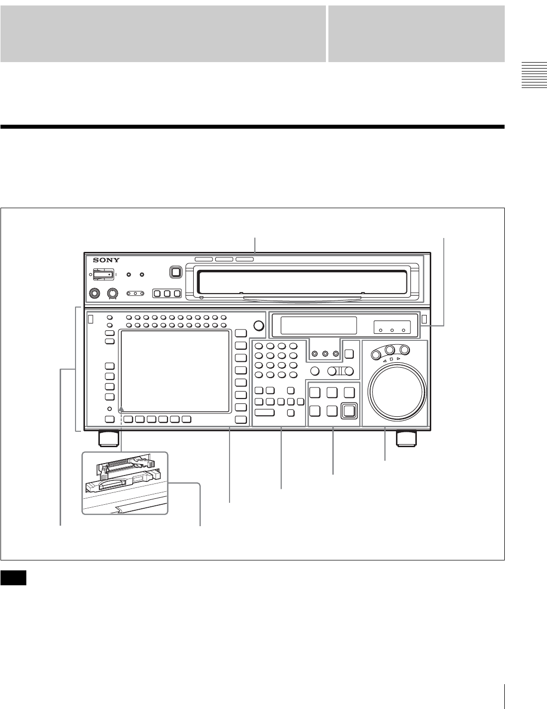
2-1 Control Panel
The control panel consists of the following sections:
• Upper control panel
• Lower control panel
• System set-up panel
Normally operate the unit with the control panel closed.
For details of how to open the control panel, for example
for system setup, refer to the Maintenance Manual.
SRW-5000
HD DIGITAL VIDEO CASSETTE RECORDER
SRW-5000
HD DIGITAL VIDEO CASSETTE RECORDER
Upper control panel 4 Display section
(see page 20)
5 Search control section
(see page 22)
3 Tape transport control section (see page 20)
2 Editing control section (see page 19)
1 Menu control section (see page 17)
System set-up panel: Access by opening the lower control panel (see page 23)
Lower control panel
Note
16 2-1 Control Panel
Chapter 2 Locations and Functions of Parts
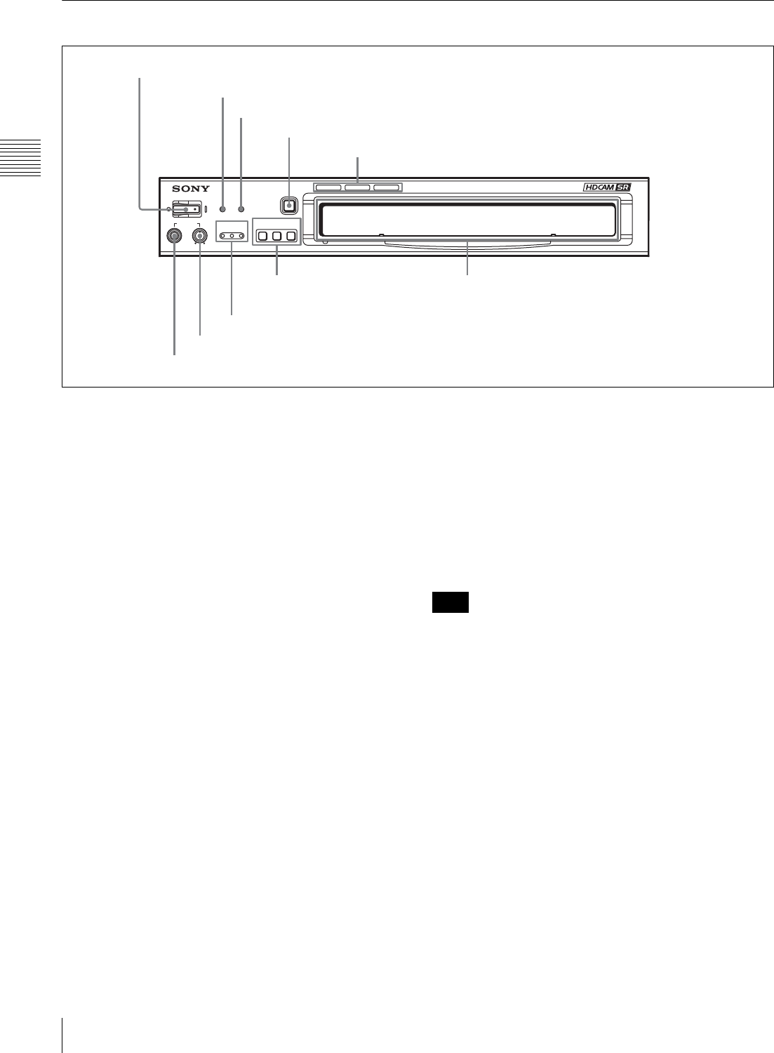
2-1-1 Upper Control Panel
aPOWER switch
Pressing on the ‘(’ side of this switch powers the unit and
lights up the information display (see page 20) and color
display (see page 18). To turn the unit off, press on the ‘a’
side of the switch.
bERROR indicator
This lights when a serious problem occurs, such as an
operational malfunction or system internal error.
You can check the details on the lower control panel.
For details, see “Error Messages and Warning Messages”
on page 134.
cWARNING indicator
This flashes when there is a fault in the unit. You can check
the details on the lower control panel.
For details, see “Error Messages and Warning Messages”
on page 134.
dEJECT button
Pressing this button automatically ejects the cassette after
several seconds.
eFormat indicators (Digital BETACAM/HDCAM/
HDCAM SR)
These show the format of the cassette loaded into the unit.
fREMOTE buttons
Press one of the following buttons, to select how the VTR
is controlled.
ETHERNET: This button lights when pressed, enabling
access from the network connected to the
ETHERNET connector on this unit.
1(9P): This button lights when pressed, enabling this unit
to be controlled from a device connected to the
REMOTE 1-IN(9P) connector or REMOTE 1-I/
O(9P) connector.
2(50P): This button lights when pressed, enabling this unit
to be controlled from a device connected to the
REMOTE 2 PARALLEL I/O(50P) connector.
When the VTR is being controlled by the external
equipment connected to the REMOTE 1-IN(9P) or
REMOTE 2 PARALLEL I/O(50P) connector, all tape
transport buttons and edit operation buttons are disabled,
except the STOP and EJECT buttons. You may also
specify the disabling or enabling of all buttons by setting
the VTR SETUP menu item 008 “LOCAL FUNCTION
ENABLE”.
gCHANNEL CONDITION indicators
These show the status of the playback signal.
Blue: The playback signal status is satisfactory.
Yellow: The playback signal is somewhat degraded, but
playback is possible.
However, if this indicator remains lit continuously,
head cleaning is required.
Red: The playback signal has deteriorated.
If this indicator remains lit continuously, head
cleaning or internal inspection is required.
SRW-5000
HD DIGITAL VIDEO CASSETTE RECORDER
EJECT
POWER
REMOTE
CHANNEL
CONDITION
PHONES
ERROR WARNING
ETHERNET
1(9P) 2(50P)
1 POWER switch
2 ERROR indicator
3 WARNING indicator
4 EJECT button
5 Format indicators
6 REMOTE buttons
7 CHANNEL CONDITION indicators
8 PHONES level control
9 PHONES jack
Cassette compartment
Note
17
2-1 Control Panel
Chapter 2 Locations and Functions of Parts
hPHONES level control
Adjusts the output level to the PHONES jack.
For details, see “5-1-2 Selecting Audio Signals” on
page 103.
iPHONES jack
Connect stereo headphones with 8 Ω impedance for audio
monitoring during recording, playback, and editing.
Adjust the headphone output level with the PHONES level
control.
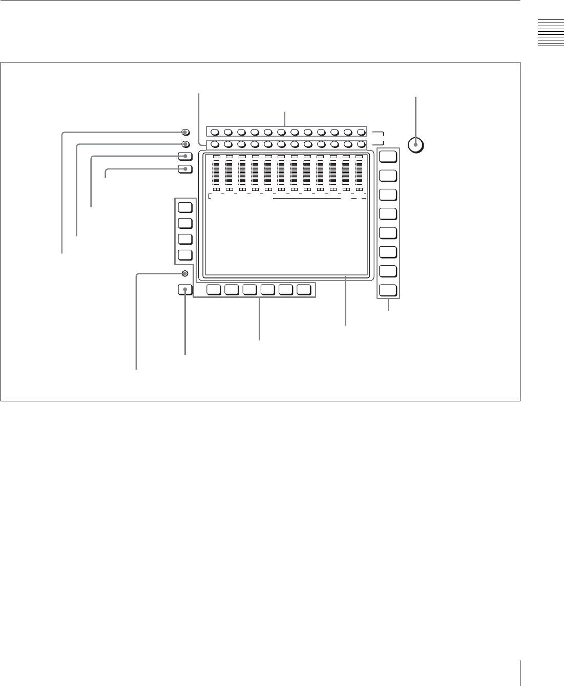
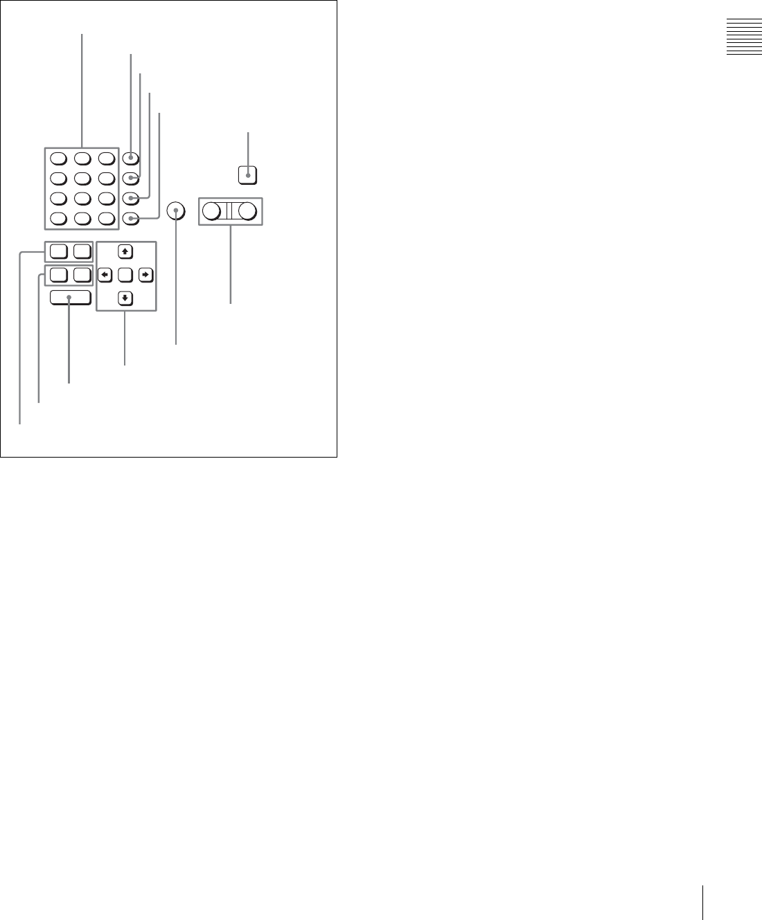
2-1-2 Lower Control Panel
1 Menu control section
aMONITOR R buttons
Select the audio signal output from the MONITOR
OUTPUT R connector. This assigns the desired channel to
the MONITOR OUTPUT R connector. If you assign more
than one channel to the same monitor output connector, a
mixed audio signal is output.
You can also make this setting using the VTR SETUP
menu item 808 “AUDIO MONITOR-R select”.
In the audio playback level adjustment mode, this is used
to select the channel to be adjusted.
bMONITOR L buttons
Select the audio signal output from the MONITOR
OUTPUT L connector. This assigns the desired channel to
the MONITOR OUTPUT L connector. If you assign more
than one channel to the same monitor output connector, a
mixed audio signal is output.
You can also make this setting using the VTR SETUP
menu item 807 “AUDIO MONITOR-L select”.
In the audio playback level adjustment mode, this is used
to select the channel to be adjusted.
cMULTI CONTROL knob
Used to set the audio recording/playback level and make
settings in the SET UP menu (see page 97).
dMenu selection buttons
These select the menu screen displayed on the display.
HOME button: Press this to go to the HOME menu
screen. The home menu provides settings for the basic
VTR operations and editing operations.
TC button: Press this to go to the TC (time code) menu
screen. In the time code menu, you can switch LTC/
MULTI
CONTROL
L
R
MONITOR
CH12CH11CH10CH9CH8CH7CH6CH5CH4CH3CH2CH1
DIAG
F1
F2
F3
F4
F5ALT F6 F7 F8 F9 F10
HOME
TC
VIDEO
AUDIO
CUE
PF1
PF2
SET UP
0
-10
-20
-30
-40
LR
OVER
CH1
dB
0
-10
-20
-30
-40
LR
OVER
CH2
dB
0
-10
-20
-30
-40
LR
OVER
CH3
dB
0
-10
-20
-30
-40
LR
OVER
CH4
dB
0
-10
-20
-30
-40
LR
OVER
CH5
dB
0
-10
-20
-30
-40
LR
OVER
CH6
dB
0
-10
-20
-30
-40
LR
OVER
CH7
dB
0
-10
-20
-30
-40
LR
OVER
CH8
dB
0
-10
-20
-30
-40
LR
OVER
CH9
dB
0
-10
-20
-30
-40
LR
OVER
CH10
dB
0
-10
-20
-30
-40
LR
OVER
CH11
dB
0
-10
-20
-30
-40
LR
OVER
CH12
dB
EDIT PRESET VIDEO TC
1 MONITOR R buttons
2 MONITOR L buttons
3 MULTI CONTROL knob
4 Menu selection buttons
5 Color display
6 Function buttons
7 ALT button
8 DIAG button
9 DISPLAY button
0 FULL/FINE button
qa PB LEVEL button
qs REC LEVEL button

18 2-1 Control Panel
Chapter 2 Locations and Functions of Parts
VITC, switch DF/NDF, set the time code to be
displayed on an external monitor, and so on.
VIDEO button: Press this to go to the VIDEO menu
screen. Use it to make video related settings.
AUDIO button: Press this to go to the AUDIO menu
screen. Use it to make audio related settings.
CUE button: Press this to go to the CUE menu screen.
The cue menu provides 10 pages to set cue points.
You can set up to 10 cue points per page. You can also
make settings for the Tele-File memory label system.
PF1 button: Press this to go to the PF1 (personal function
1) menu screen. You can register frequently-used
items in the PF1 menu. The factory default setting is
blank.
PF2 button: Press this to go to the PF2 (personal function
2) menu screen. You can register frequently-used
items in the PF2 menu. The factory default setting is
blank.
SET UP button: Press this to go to the SET UP menu
screen. The setup menu provides functions to save
menu settings in VTR banks or save to a memory
stick, registration operations in the PF buttons, VTR
SETUP menu settings, and so on.
For details of menus, see Chapter 4 “Menu Settings” on
page 37.
eColor display
This comprises principally the audio level display and
menu display.
Audio Level display:
In recording mode or E-E mode1), this displays the audio
recording levels.
In playback mode or CONFI mode, this displays the
playback levels.
The display mode can be changed with the FULL/FINE
button. The factory default display is a reference level of
–20 dB, and peak level 0 dB.
Menu display:
This displays the menu screen selected by the menu
selection buttons.
Each menu screen shows the functions assigned to the
function buttons ([F1] to [F10]), and shows simultaneously
information required for time code display settings and so
on.
1) E-E mode
An abbreviation for Electric-to-Electric mode. In this mode, video or audio
input signals are passed and output only through the VTR’s internal
circuitry, and not through the magnetic conversion system comprising tape
and heads.
fFunction buttons
Activates the functions in each menu.
gALT (alternative) button
Press to change the items displayed on the current menu.
Press again to return to the original items.
hDIAG (diagnostic) button
Hold down the SFT button (see page 19) in the editing
control section and press this switch to switch to the DIAG
menu.
iDISPLAY button
This displays the down-converted output signal in the
whole color display.
• Depending on the system settings, it may not be possible
to output some signals.
• This function is for a quick check of the output signal,
and cannot be used as a monitor.
jFULL/FINE button
This selects the audio level meter display range.
FULL: The audio level meter display is from –60 dB to 0
dB, or –40 dB to +20 dB. Select which of these ranges
(peak level: 0 dB or +20 dB) is displayed in the VTR
SETUP menu item 814 “LEVEL METER SCALE”.
FINE: The audio level meter display range is expanded,
and displayed with a scale in steps of 0.25 dB. The
reference marker LED at the center of the level meter
display range lights. When the audio level exceeds the
maximum display range, the top OVER display
flashes. When under the minimum display range, the
bottom line flashes.
kPB (playback) LEVEL button
Press this button to enter the playback audio level
adjustment mode. In this mode, you can use the
MONITOR R button to select the adjustment target
channels from channels 1 to 12. While watching the audio
level meter, turn the MULTI CONTROL knob for a
desired audio level.
Clicking the MULTI CONTROL knob resets the playback
audio level to the factory set level (a reference level of 0
dB is displayed for a +4 dBm input). Clicking the MULTI
CONTROL knob again restores the adjusted level.
Press this button again to exit from the playback audio
level adjustment mode, and the MONITOR L and R
buttons return to the normal status (this status is called the
“MONITOR SELECT mode”).
lREC (recording) LEVEL button
Press this button to enter the recording audio level
adjustment mode. In this mode, you can use the
MONITOR L button to select the adjustment target
channels from channels 1 to 12. While watching the audio
level meter, turn the MULTI CONTROL knob for a
desired audio level.
Clicking the MULTI CONTROL knob resets the recording
audio level to the factory set level (a reference level of 0
dB is displayed for a +4 dBm input). Clicking the MULTI
CONTROL knob again restores the adjusted level.
Notes
19
2-1 Control Panel
Chapter 2 Locations and Functions of Parts
Press this button again to exit from the recording audio
level adjustment mode, and the MONITOR L and R
buttons return to the normal status (this status is called the
“MONITOR SELECT mode”).
2 Editing control section
aNumeric buttons and +/– buttons
Press to input time data or edit points data at the cursor
position in menu display. Press buttons 0 to 5 while
holding down the SFT button to input hexadecimal A to F
for user bits. Use the +/– buttons to increase or decrease
settings.
bSFT (shift) button
Press buttons 0 to 5 while holding down this button to
input hexadecimal A to F for user bits.
Use also in combination with other buttons to perform
other operations.
cRCL (recall) button
Press to recall the previous setting, etc.
dCLR (clear) button
Press to clear input data.
eSET button
Press to finalize input data.
fINPUT CHECK button
While you hold down this button, the input signal is output
from the monitor output connector, so that you can monitor
the input video and audio.
When the LTC/VITC time code is shown on the display,
you can check the time code generator.
gPLAYER/RECORDER buttons
Select which VTR is to be controlled by this VTR’s control
panel during editing when this VTR is used as a recorder
and an external VTR is connected to the REMOTE 1-
IN(9P) or REMOTE 1-I/O(9P) connector as a player.
PLAYER: The tape transport buttons and editing
operation buttons on the control panel control the
external player VTR.
RECORDER: The tape transport buttons and editing
operation buttons on the control panel control the
recorder VTR (this VTR).
The PLAYER/RECORDER buttons have no effect when
using this VTR alone.
hAUTO button
When this button is pressed, it lights up and auto edit mode
is activated.
iCursor buttons
Use to move the cursor (shown in reverse video) on the
display. Also use to change menu settings.
jENTRY button
Press to enter an edit or cue point.
While holding down this button, press either the AUDIO
IN or AUDIO OUT button, or the IN or OUT button.
kIN/OUT buttons
To set a IN or OUT point during editing, press either of
these buttons while holding down the ENTRY button.
lAUDIO IN/AUDIO OUT buttons
To set an AUDIO IN or AUDIO OUT point during insert
editing, press either of these buttons while holding down
the ENTRY button.
789
SFT
456
RCL
123
CLR
0
EF
BCD
AUTO
AUDIO
VIDEO
PLAYER RECORDER
INPUT
CHECK
A
+–
SET
IN OUT
ENTRY
IN OUT
1 Numeric buttons and +/– buttons
2 SFT button
3 RCL button
4 CLR button
5 SET button
6 INPUT CHECK
button
7 PLAYER/
RECORDER
buttons
8 AUTO button
9 Cursor buttons
0 ENTRY button
qa IN/OUT buttons
qs AUDIO IN/AUDIO OUT buttons
20 2-1 Control Panel
Chapter 2 Locations and Functions of Parts
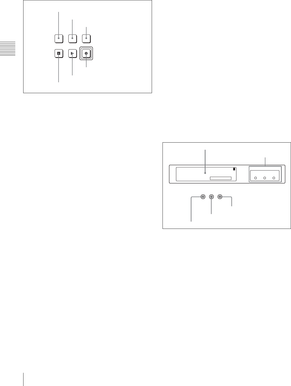
3 Tape transport control section
aSTANDBY button
Press this button in other than standby mode to make it
light up and place the VTR in standby mode. The head
drum rotates in standby mode, thereby shortening the time
required for the tape to start.
Press this button while in standby mode to turn the button
off and exit from standby mode. The head drum stops
rotating and the tape tension is released. If the VTR
remains in standby mode for more than eight minutes
(factory setting), standby mode is automatically canceled
in order to safeguard the tape.
bPREROLL button
Press to run the tape to the preroll point (a position factory
set to five seconds before the IN point).
Press this button while holding down the IN, OUT,
AUDIO IN or AUDIO OUT button to cue up the tape at the
corresponding edit point.
For details on changing the preroll time, see “4-2-6
Setting the Preroll Time (PREROLL TIME)” on page 52.
cPREVIEW/REVIEW button
After the edit points are set, press this button to preview,
on the monitor connected to the recorder, the effect of the
edit before it is performed. In this operation, the tape runs,
but no editing is carried out.
If you press this button after carrying out an edit, the
results of the edit are played back on the monitor
connected to the recorder.
dREC/EDIT (recording/edit) button
Press this button while holding down the PLAY button to
start recording.
If you press this button in play mode, manual editing
begins. After setting edit points, if you press this button
while the AUTO button is lit, automatic editing is
performed.
ePLAY button
Press to start playback.
Press this button while holding down the REC/EDIT
button to start recording.
Pressing this button during recording or manual editing
changes the VTR to playback mode.
fSTOP button
Press this button to stop recording or playback.
When you insert the cassette, the VTR automatically
enters STBY OFF mode.
The STOP button flashes in the following cases.
•The [F2] (SERVO REF) button in the PF1 menu is set to
“input” but there is no video input signal.
•The [F2] (SERVO REF) button in the PF1 menu is set to
“ext” but there is no external reference video signal.
• The input signal is out of synchronization with the
external reference video signal.
You can change the setting of the VTR SETUP menu item
102 “REFERENCE SYSTEM ALARM” so that the STOP
button will not flash in these cases.
4 Display section
aInformation display
The information display shows a number of different
pages. To change the page displayed, with no other items
selected in the menu display (HOME, TC, VIDEO,
AUDIO, PF1, and PF2), turn the MULTI CONTROL knob
while holding it down.
The currently selected page number also appears at the
upper right of the information display.
Page 1: System status
SYS: Shows the recording system information (signal
standard and tape format).
PB: Shows the information recorded on the tape (signal
standard and tape format) while being played back.
FC: Shows the converted signal standard when an HKSR-
5001 board is installed.
TC: Shows the LTC/VITC and DF/NDF settings, or the
time code sent to the external monitor.
PREVIEW/
REVIEW
REC/EDIT
PREROLLSTANDBY
PLAYSTOP
1 STANDBY button
2 PREROLL button
3 PREVIEW/REVIEW button
4 REC/EDIT button
5 PLAY button
6 STOP button
REC
INHIBIT SERVO
EXT
SD
EXT
HD
REF SYNC
INPUT
VIDEO
PREREAD
SYS: 23.98PSF 1080 4:2:2 HDCAM-SR
: -------- ----- ----- --------PB
: 59.94i 1080 4:2:2 FC
T*R 02:01.01:28
1
1 Information display
2 REF SYNC indicators
3 PREREAD indicator
4 SERVO indicator
5 REC INHIBIT indicator

21
2-1 Control Panel
Chapter 2 Locations and Functions of Parts
Page 2: System status
ACTIVE LINE: Shows the status of 1080/1035
conversion active line.
1080t1080
1080t1035(CROP)
1080t1035(CONV)
1035t1035
1035t1080(PANEL)
1035t1080(CONV): Shows the current conversion
status.
- - - - -: Cannot be converted.
OFF: No conversion done.
DOWN CONV. OUTPUT: Shows the output status of the
down converter.
ACTIVE: Output.
MUTING: No output.
EOS: Appears at the location of the time code for the valid
end of the previous recording.
Page 3: Phase (OUTPUT)
HD SDI OUTPUT ADV.: Shows the phase of the main
line HD SDI output.
OFF: In phase with reference.
–90H: 90H (HD) advanced with respect to reference.
DOWN CONV. OUTPUT ADV.: Shows the phase of the
down converter output.
OFF: In phase with reference.
–2H: 2H (SD) advanced with respect to reference.
Page 4: Phase (AUDIO)
AUDIO PB OUTPUT ADV.: Shows the phase of the
audio output signal.
OFF: Output in phase with the video output signal.
–1Frame: Output one frame advanced with respect to
the video output signal.
AUDIO INPUT DELAY: Shows the recording phase of
the audio input signal.
OFF: Recorded in phase with the video output signal.
+1Frame: Recorded one frame delayed with respect to
the video input signal.
AES/EBU & ANA OUTPUT: Shows the phase of the
AES/EBU and ANALOG AUDIO outputs.
REF: Output in phase with reference.
FC: In phase with the FC output.
–90H(HD): 90H (HD) advanced with respect to
reference.
–2H(SD): 2H (SD) advanced with respect to
reference.
Page 5: Phase (TC)
TC INPUT DELAY: Shows the recording phase of the
input time code.
OFF: Recorded in phase with the input video signal.
+1Frame: Recorded one frame delayed with respect to
the input video signal.
LTC OUTPUT: Shows the phase of the output LTC.
LINE: Output in phase with the main line HD SDI
output.
FC: Output in phase with the FC output.
Page 6: Meta Data
The display changes depending on the tape format in use.
• HDCAM-SR
META DATA LINE(REC): Shows the status of the
three lines for metadata recording on this unit.
META DATA LINE(OUT): Shows the status of the
three lines of main HD SDI output into which
metadata is multiplexed.
META DATA LINE(FC): Shows the status of the three
lines of output from the optional HKSR-5001
format converter board into which metadata is
multiplexed.
META DATA LINE(SD): Shows the status of the three
lines of SD SDI output into which metadata is
multiplexed.
• HDCAM
Displays L1/L2/DID/SDID. This combination is
counted as 1 packet. Up to 3 packets can be recorded.
On the SRW-5500, the system settings related to
recording are shown on the left. If data is detected in the
input signal, the L1/L2 values are highlighted. The right
side shows playback values detected on the tape.
The ACTIVE LINE setting displayed on page 2 can be
made in the SYSTEM screen. The phase settings displayed
on pages 3 to 5 and the settings relating to META DATA
recording displayed on page 6 can be made in the PHASE
SET/META DATA menu under the ALT+OTHERS
CHECK menu in the MAINTENANCE menu.
For details, refer to the Installation Manual.
bREF SYNC (reference signal) indicators
These indicate the signal selected as the reference signal.
If there is no reference signal input to the selected
connector, the STOP button flashes.
EXT SD: Lights when “extern SD” is selected by the VTR
SETUP menu item 006 “EXTERNAL REFERENCE
select”.
EXT HD: Lights when “extern HD” is selected by the
VTR SETUP menu item 006 “EXTERNAL
REFERENCE select”.
INPUT VIDEO: Lights when “INPUT” is selected by the
VTR SETUP menu item 005 “SERVO/AV
REFERENCE select”.
cPREREAD indicator
Lights up during preread mode.
For more information about PREREAD, see “6-2-2
Animation Editing” on page 127.
Note
22 2-1 Control Panel
Chapter 2 Locations and Functions of Parts
dSERVO indicator
Lights up when the drum servo and capstan servo are
locked.
eREC INHIBIT indicator
Only when this indicator is not lit, you can make settings
for assemble/insert editing mode, and carry out recording
and playback operations.
The status of this indicator depends on the setting of the
[F2] (REC INH) button in the HOME menu and the state
of the record-protect plug on the cassette.
a) Toggling between lit/flashing settings is possible using the VTR SETUP
menu item 104 “REC INHIBIT LAMP FLASHING”.
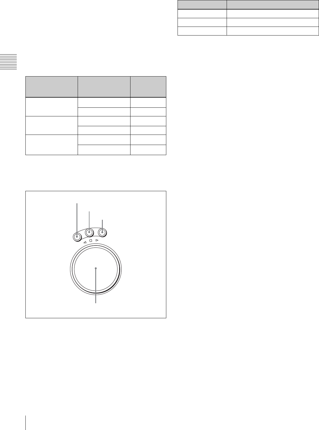
5 Search control section
aSHUTTLE button
Press to enter shuttle mode. In this mode, the button lights
and playback at the speed corresponding to the angle of
rotation of the search dial is possible. The playback speed
range depends on the frame frequency of the unit. In this
mode, the search dial clicks at the positions for 0 (still
picture) and ±10 times normal playback speed (HDCAM/
Digital Betacam) or ±8 times normal playback speed
(HDCAM-SR).
bJOG button
Press to select jog mode. In this mode, the button lights up
and playback is possible at –1 to +1 times normal speed, ±2
times normal speed (HDCAM/HDCAM-SR), or ±3 times
normal speed (Digital Betacam) (determined by the setting
in the VTR SETUP menu item 107 “JOG DIAL
RESPONSE”). In this mode, the search dial does not click.
cVAR (variable) button
Press to select variable speed playback mode for noiseless
playback in the range from –1 to +2 times normal speed
(HDCAM/HDCAM-SR) or –1 to +3 times normal speed
(Digital Betacam). Playback exceeding this speed range is
not possible. The search dial clicks at the positions for still-
picture and normal playback speed.
dSearch dial
Rotate to search for edit points. Rotate the dial clockwise
for forward playback (the B indicator lights up) or
counterclockwise for reverse playback (the b indicator
lights up). The x indicator lights up while the VTR is in
stop mode.
Shuttle mode: The playback speed corresponds to the
angle of rotation of the search dial. The playback
speed range depends on the frame frequency of the
unit. (See item 1 SHUTTLE button.) The dial clicks
at the positions for 0 (still picture) and ±10 times
normal playback speed (HDCAM/Digital Betacam)
or ±8 times normal playback speed (HDCAM-SR).
Jog mode: The playback speed corresponds to the
rotational speed of the dial (–1 to +1 times normal
speed, ±2 times normal speed (HDCAM/HDCAM-
SR), or ±3 times normal speed (Digital Betacam))
depending on the setting of the VTR SETUP menu
item 107 “JOG DIAL RESPONSE”). The dial does
not click.
Variable speed playback mode: Noiseless playback is
possible in the range from –1 to +2 times normal
speed (HDCAM/HDCAM-SR) or –1 to +3 times
normal speed (Digital Betacam). The speed settings
can be changed using the menu. The dial clicks at the
positions for still-picture and normal playback speed.
Capstan override mode: Rotating the dial while holding
down the PLAY button changes the playback speed
by up to ±15%.
Setting of the [F2]
(REC INH) button in
the HOME menu
State of the record-
protect plug on the
cassette
REC INHIBIT
indicator
all Recording disabled Lit/flashinga)
Recording allowed Lit
crash REC, video/
CTL, audio/CTL
Recording disabled Lit/flashinga)
Recording allowed Unlit
off Recording disabled Lit/flashinga)
Recording allowed Unlita)
R
E
V
E
R
S
E
F
O
R
W
A
R
D
S
H
U
T
T
L
E
J
O
G
V
A
R
1 SHUTTLE button
2 JOG button
3 VAR button
4 Search dial
Frame frequency Playback speed
23.98/24 Hz Ranging from ±50
25 Hz Ranging from ±48
29.97/30 Hz Ranging from ±40
23
2-1 Control Panel
Chapter 2 Locations and Functions of Parts
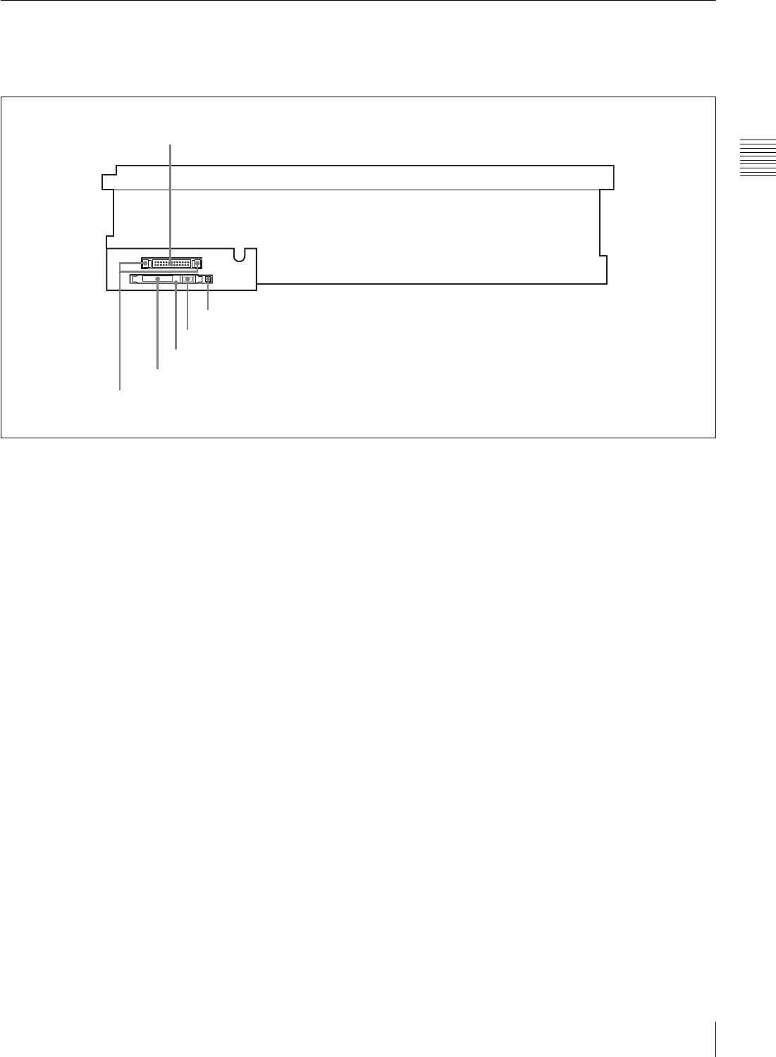
2-1-3 System Set-Up Panel
Lift the lower control panel up to its horizontal position to
access the system set-up panel.
For details of opening and closing the control panel, refer
to the Maintenance Manual.
For details, see “3-4 Using a Memory Stick” on page 35.
CONTROL PANEL
CONTROL PANEL connector
Card slot eject button
Memory stick eject button
Memory stick receptacle
PCM CIA card slot
Harness restraint
25
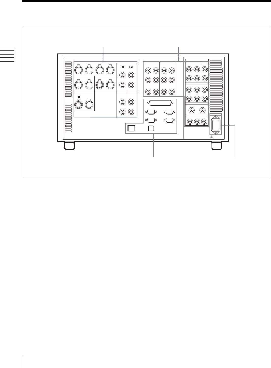
2-2 Connector Panel
Chapter 2 Locations and Functions of Parts
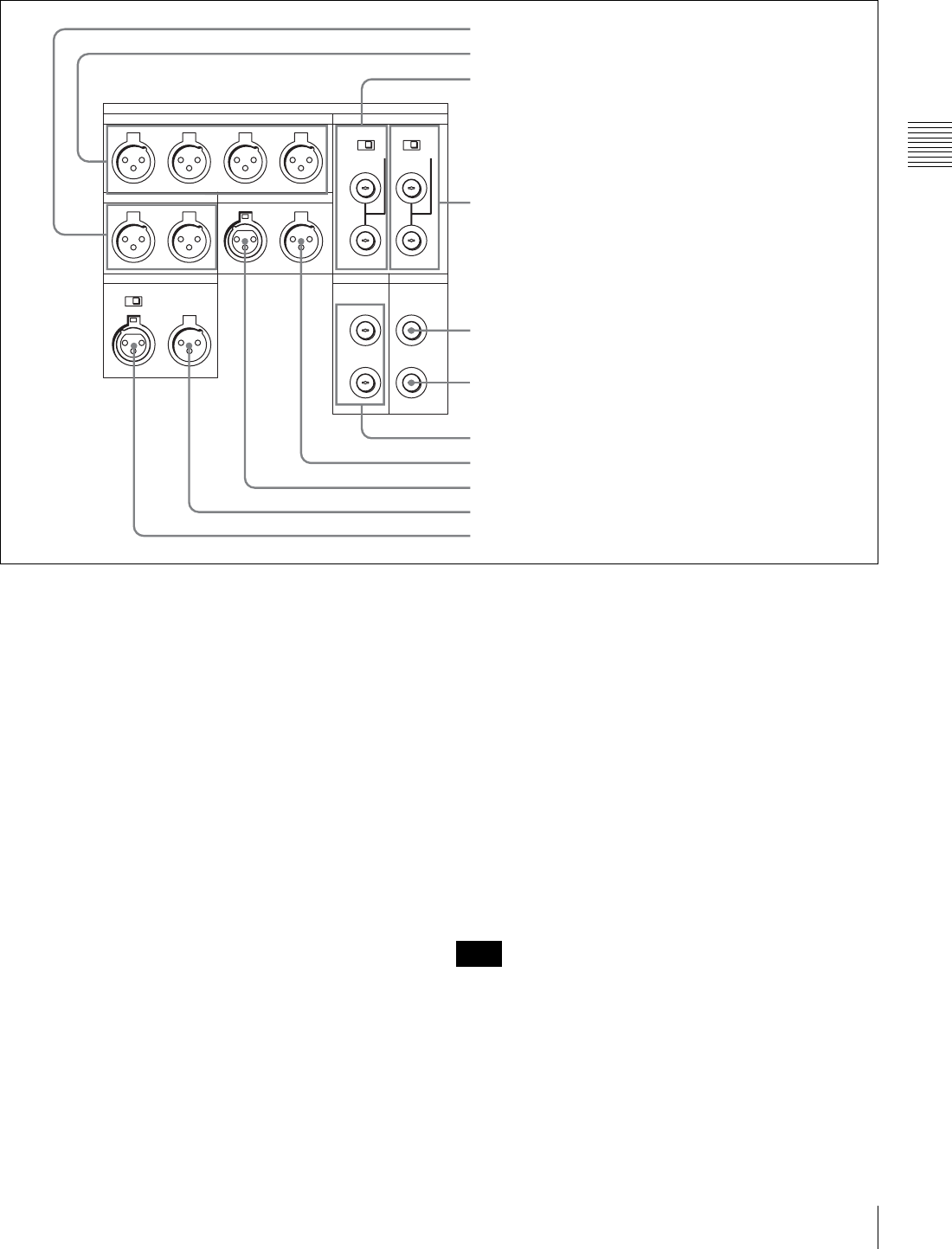
1 ANALOG I/O (input/output) section
aMONITOR OUTPUT L/R connectors
(XLR-3-31, male)
These output the audio signals for monitoring L and R
channels. To select the signals to output, use the
MONITOR R and MONITOR L buttons on the lower
control panel.
For details, see “5-1-2 Selecting Audio Signals” on
page 103.
bAUDIO OUTPUT CH1 to CH4 connectors
(XLR-3-31, male)
These output up to four analog audio signal lines (channels
1 to 4).
cREF. INPUT 1 connectors (BNC) and 75Ω
termination switch
Input a reference video signal of the selected field
frequency. Select HD or SD with the VTR SETUP menu
item 006 “EXTERNAL REFERENCE select”. When HD
is selected, input a tri-level SYNC signal. When SD is
selected, input a video signal with chroma burst (VBS) or
a monochrome video signal (VS).
A loop-through connection is possible. Set the 75Ω
termination switch to OFF if you are using a loop-through
connection and set it to ON if you are not using a loop-
through connection.
dREF. INPUT 2 connectors (BNC) and 75Ω
termination switch
Input a reference video signal of the field frequency
selected for the format converter output. Select HD or SD
with the VTR SETUP menu item A08 “FC REFERENCE
select”. When HD is selected, input a tri-level SYNC
signal for external synchronization. When SD is selected,
input a video signal with chroma burst (VBS) or a
monochrome video signal (VS). A loop-through
connection is possible. Set the 75Ω termination switch to
OFF if you are using a loop-through connection and set it
to ON if you are not using a loop-through connection.
eSD OUT SYNC connector (BNC)
This outputs an NTSC or PAL signal for external
synchronization.
The output phase is the same as that of the composite
signal output from the SD OUT COMPOSITE
(MONITOR) connector.
Because the output phase changes with the operation mode
of the VTR, use this for synchronization with the video
monitor.
AUDIO OUTPUT
MONITOR OUTPUT
CUE
TIME CODE
ANALOG I/O
HD REF. OUT SD OUT
CH1
R L IN OUT
1
OFF ON
600
OFF ON
75 75
2 (OPTION)
OFF ON
OUT 1
2
SYNC
COMPOSITE
(MONITOR)
CH2 CH3 CH4
IN
REF. INPUT
1 MONITOR OUTPUT L/R connectors
2 AUDIO OUTPUT CH1 to CH4 connectors
3 REF. INPUT 1 connectors and 75Ω termination switch
4 REF. INPUT 2 connectors and 75Ω termination switch
5 SD OUT SYNC connector
6 SD OUT COMPOSITE (MONITOR) connector
7 HD REF. OUT connectors
8 TIME CODE OUT connector
9 TIME CODE IN connector
0 CUE OUT connector
qa CUE IN connector (SRW-5500 only)
Note

26 2-2 Connector Panel
Chapter 2 Locations and Functions of Parts
fSD OUT COMPOSITE (MONITOR) connector
(BNC)
Outputs an analog composite signal for a video monitor.
When the ALT/[F6] (CHARA SUPER) setting in the TC
menu is on, character signals such as time codes are
superimposed on the output.
gHD REF. OUT connectors (BNC)
Output an HD tri-level sync signal during tape playback.
hTIME CODE OUT connector (XLR 3-31, male)
Outputs the following time codes according to the VTR
operation mode.
In playback mode: Playback time code
In recording mode: Time code generated by the internal
time code generator, or time code input to the TIME
CODE IN connector.
To select the output signal, use the VTR SETUP menu
item 613 “TC OUTPUT SIGNAL IN REGENE MODE.”
iTIME CODE IN connector (XLR 3-32, female)
Accepts external time code for recording to tape. Connect
to the time code output connector of the external
equipment.
jCUE OUT (cue output) connector
(XLR 3-31, male)
Outputs cue track audio during HDCAM or Digital
Betacam playback.
There is no cue track on an HDCAM-SR tape, and
therefore no output.
kCUE IN (cue input) connector (XLR 3-31, female)
(SRW-5500 only)
Enabled only during HDCAM format recording.
Setting Description
off tape In playback mode, playback time code signal
is output. In recording mode, TCG time code
signal is output.
regene Only when the servo is locked in playback
mode, playback time code signal is
regenerated and output. In all other cases,
output is the same as for the “off tape” setting.
through The time code signal from the TIME CODE IN
connector is output as it is. (Used for cascade
connections.)
(For more information about cascade
connections, see “3-1-3 Cascade
Connection” on page 31.)
Note
27
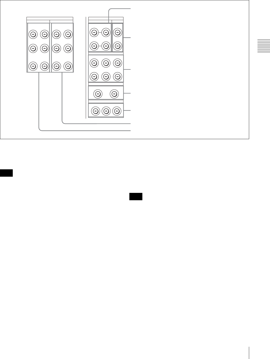
2-2 Connector Panel
Chapter 2 Locations and Functions of Parts
2 DIGITAL I/O (input/output) section
aHD SDI (SDI video/audio) INPUT A/B connectors
(BNC)
These accept SDI video/audio signals.
The INPUT MONITOR connectors are for use with an
input monitor and does not follow the standards for output.
bFC OUT B (FORMAT CONV. OUTPUT B
(OPTION)) connectors (BNC)
These are only effective when the optional HKSR-5001
format converter board is installed. When the output
format is selected as 4:4:4, LINK B is output, and when the
output format is selected as 4:2:2 it is not output.
cHD SDI (SDI video/audio) OUTPUT connectors
(BNC)
These output three sets of SDI video/audio signals.
When the ALT/[F6] (CHARA SUPER) buttons are set to
ON in the TC menu, time data or other text data is
superimposed on the signal output from the MONITOR A
connector.
dFORMAT CONV. OUT (OPTION) connectors
(BNC)
These output two sets of format-converted video/audio
signals.
When the ALT/[F5] (PD CHARA) buttons are set to ON in
the TC menu, the output has time data or other text
superimposed on the signal.
This is only valid when the optional HKSR-5001 format
converter board is installed. When the output format is
selected as 4:4:4, LINK A is output.
eSD SDI (1/2/monitor) OUT connectors (BNC)
These output three sets of video/audio signals. When the
ALT/[F6] (CHARA SUPER) buttons are set to ON in the
TC menu, time data or other text data is superimposed on
the output from the MONITOR OUTPUT L/R connector.
fDIGITAL I/O (AES/EBU) OUTPUT connectors
(BNC)
These output digital signals in AES/EBU format for
channels 1 to 12.
gDIGITAL I/O (AES/EBU) INPUT connectors
(BNC)
These accept digital signals in AES/EBU format for
channels 1 to 12.
HD SDI INPUT FC OUT BINPUT
HD SDI OUTPUT
FORMAT CONV. OUT (OPTION)
SD SDI OUT
A
DIGITAL I/O (AES/EBU)
CH1/2 CH3/4 CH1/2 CH3/4
CH5/6 CH7/8 CH5/6 CH7/8
CH9/10 CH11/12 CH9/10 CH11/12
B(OPTION)
1
2
B INPUT
MONITOR
A
1
12
1 2 MONITOR
MONITOR
AUDIO
OUTPUT
AUDIO
2 MONITOR
B(OPTION)
A
B(OPTION)
A
B(OPTION)
INPUT
MONITOR
DIGITAL I/O
1 HD SDI INPUT A/B connectors
2 FC OUT B connectors
4 FORMAT CONV. OUT (OPTION) connectors
5 SD SDI OUT connectors
6 DIGITAL I/O (AES/EBU) OUTPUT connectors
7 DIGITAL I/O (AES/EBU) INPUT connectors
3 HD SDI OUTPUT connectors
Note
Note
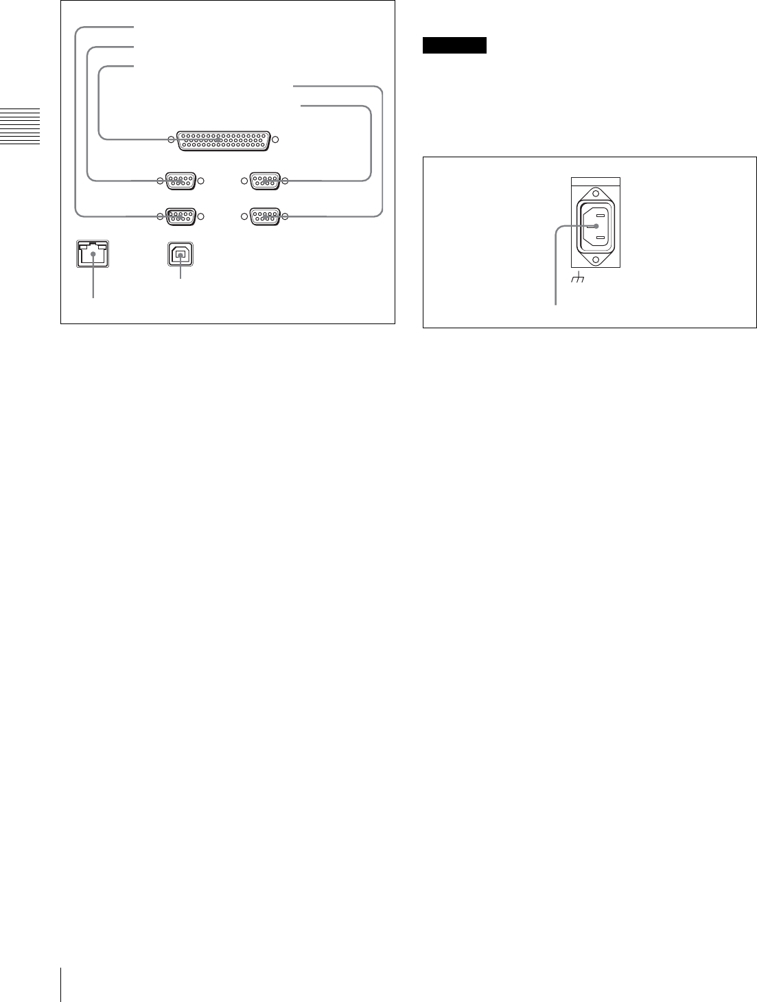
28 2-2 Connector Panel
Chapter 2 Locations and Functions of Parts
3 Remote input/output section
aRS232C connector (RS-232C serial interface)
(D-sub 9-pin)
This is used for manufacturing and services.
bREMOTE 1-IN(9P) connector (D-sub 9-pin,
female)
Use this, with the supplied 9-pin remote control cable, to
connect the unit to another SRW-5000/5500 unit or
another HD VTR unit to carry out editing with a BVE-
series editor BVE-900/910/2000/9000/9100.
cREMOTE 2 PARALLEL I/O(50P) connector (D-
sub 50-pin, female)
Inputs an external remote control signal.
For details, refer to the Maintenance Manual Volume 1.
dVIDEO CONTROL (Digital Video Processor
Control) connector (D-sub 9-pin, female)
Connects to the optional HKDV-900 HD Digital Video
Controller to enable remote control of the internal digital
video processor. Turn off the power before connecting the
remote controller.
eREMOTE 1-I/O(9P) connector (D-sub 9-pin,
female)
Use this, with the supplied 9-pin remote control cable, to
connect the unit to another SRW-5000/5500 unit or
another HD VTR unit to carry out editing with a BVE-
series editor BVE-900/910/2000/9000/9100.
fUSB connector
This is used for manufacturing and services.
gETHERNET connector
Used for monitoring the VTR by SNMP, or for setting or
changing VTR settings by HTTP.
For safety, do not connect the connector for peripheral
device wiring that might have excessive voltage to this
port. Follow the instructions for this port.
4 Power supply
-AC IN connector
Connects to an AC outlet using an appropriate power cord.
REMOTE 2 PARALLEL I/O(50P)
ETHERNET
REMOTE 1-IN(9P) REMOTE 1-I/O(9P)
RS232C
USB
VIDEO CONROL
1 RS232C connector
2 REMOTE1-IN(9P) connector
3 REMOTE 2 PARALLEL I/O(50P) connector
4 VIDEO CONTROL connector
5 REMOTE1-I/O(9P) connector
6 USB connector
7 ETHERNET connector
CAUTION
AC IN
-AC IN connector
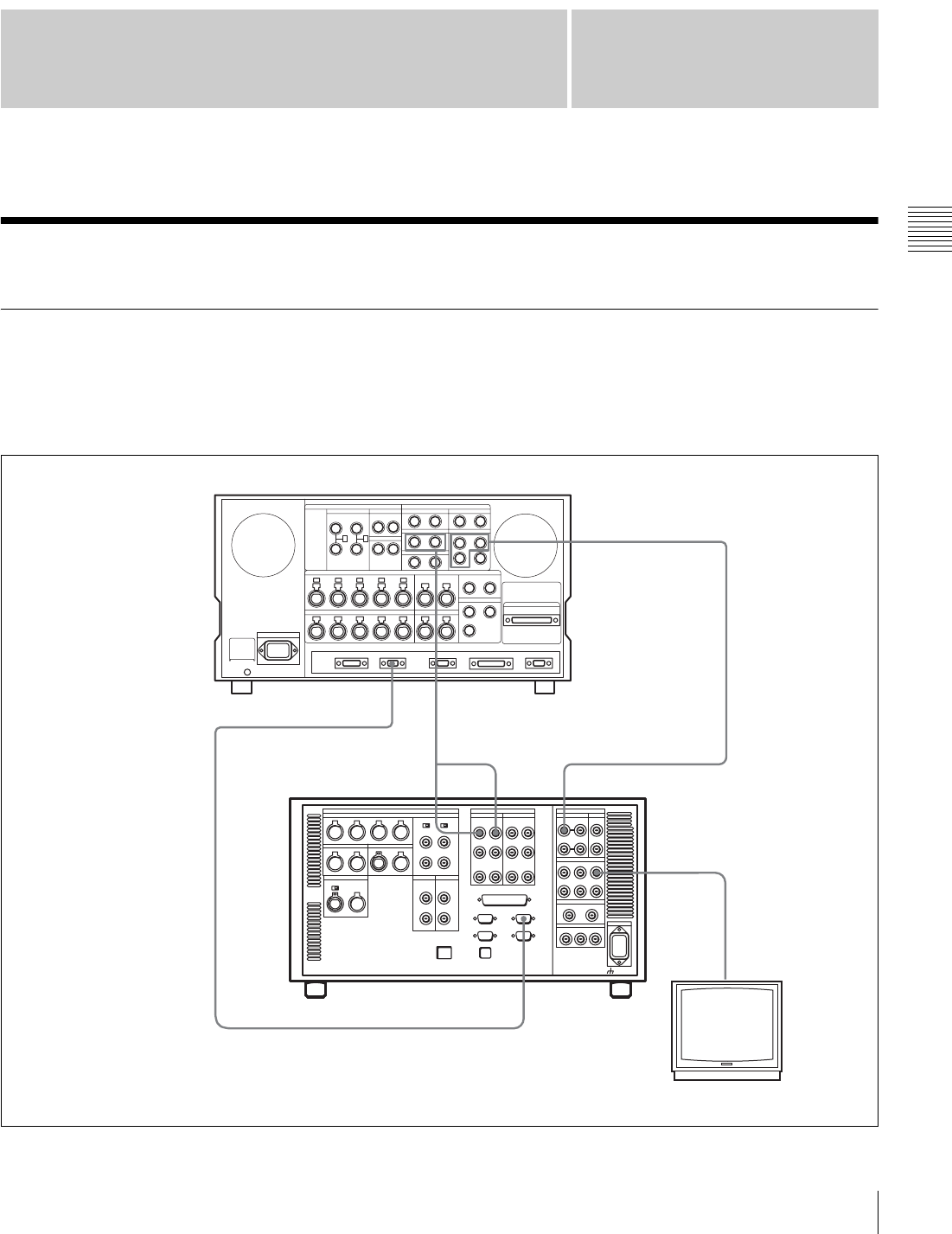
29
3-1 Connecting External Equipment
Chapter
Chapter 3 Setting Up the VTR
3
Setting Up the VTR
3-1 Connecting External Equipment
3-1-1 Making HD Digital Connections
This example shows the connections when using an HDW-
F500 as player and an SRW-5000/5500 as recorder, in
59.94i or 60i mode.
See “Specifications” in the Appendix (page 131) for
recommended XLR/BNC and P/S converters.
HD SDI OUTPUT
AUDIO
OUTPUT
HD SDI INPUT
HD SDI OUTPUT
REMOTE (9P)
REMOTE 1-I/O(9P)
DIGITAL I/O INPUT
HDW-F500 (Player)
9-pin remote control cable
SRW-5000/5500 (Recorder) a)
a) The figure shows the SRW-5500. Video monitor
(HD serial monitor)
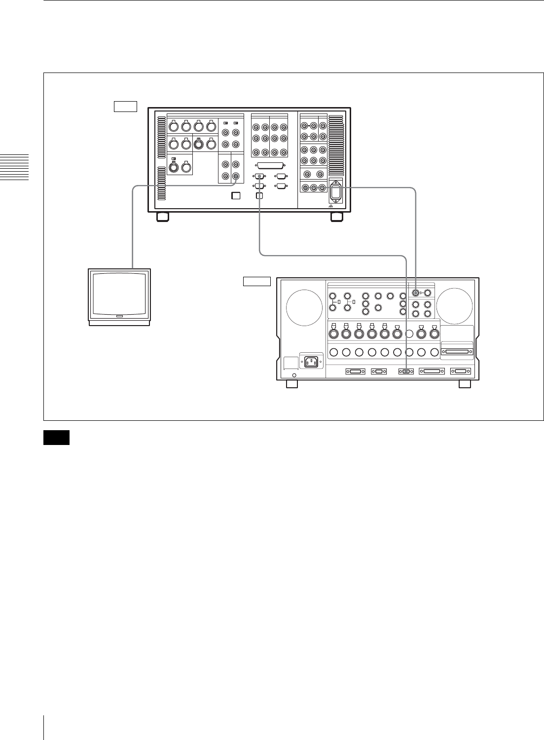
30 3-1 Connecting External Equipment
Chapter 3 Setting Up the VTR
3-1-2 Making NTSC/PAL Digital Connections
This example shows how to connect two VTRs, an SRW-
5000/5500 as the player and a DVW-500 D-1 Component
Digital VTR as the recorder.
For color frame editing using the SRW-5000/5500 as the
player and an NTSC/PAL digital device as the recorder, set
the VTR SETUP menu item 005 “SERVO/AV
REFERENCE select” to “external” and set the menu item
006 “EXTERNAL REFERENCE select” to “extern SD”.
REMOTE 1-IN(9P)
SD OUT
COMPOSITE (MONITOR)
SD SDI OUT
DIGITAL I/O SERIAL V/A INPUT
REMOTE 1-OUT
SRW-5000/5500 (Player) a)
BNC cable
9-pin remote control cable
BNC cable
Video monitor
(NTSC/PAL monitor)
DVW-500 (Recorder)
a) The figure shows the SRW-5500.
Input
Output
Note
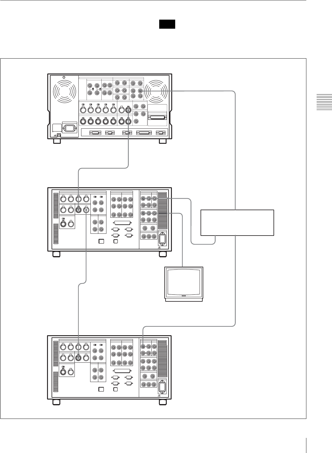
31
3-1 Connecting External Equipment
Chapter 3 Setting Up the VTR
3-1-3 Cascade Connection
This example shows how to connect multiple SRW-5000/
5500 VTRs together for simultaneous recording.
On the recording VTRs, set the VTR SETUP menu item
613 “TC OUTPUT SIGNAL IN REGENE MODE” to
“through”.
Note
HD SDI OUTPUT
HD SDI INPUT
TIME CODE IN
TIME CODE OUT
TIME CODE OUT
HD SDI
OUTPUT
HD SDI INPUTTIME CODE IN
HDW-F500 (Player)
BNC cable
Digital video distributor
HKPF-103M
SRW-5000/5500 (Recorder) a)
Video monitor
(HD serial monitor)
SRW-5000/5500 (Recorder) a)
a) The figure shows the SRW-5500.
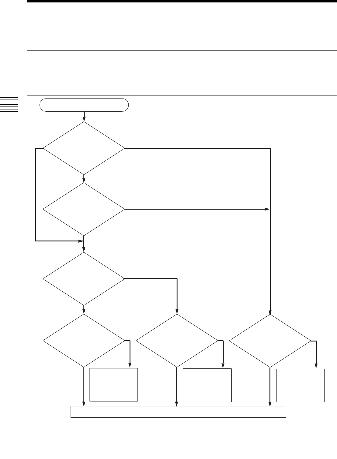
32 3-2 Reference Signals
Chapter 3 Setting Up the VTR
3-2 Reference Signals
This section describes how reference signals for the video
output are selected.
3-2-1 Reference Signals for Output Video
Depending on the operating condition, VTR SETUP menu
settings, the input signal, and the video output signal from
the VTR can be synchronized as follows.
Start
ext. What is the setting of
the VTR SETUP menu
item 005 “SERVO/AV
REFERENCE select”?
input
auto
Is the VTR currently
recording or is EDIT
PRESENT on?
No
Yes
What is the setting
of the VTR SETUP
menu item 006
“EXTERNAL
REFERENCE
select”?
extrn SD
extrn HD
Is there a signal of the
correct frequency on
the REF. INPUT 1 or
2 a) connector?
Is there a signal of the
correct frequency on
the REF. INPUT 1 or
2 a) connector?
Yes Yes Is there an input
signal on the HD SDI
INPUT connector?
Yes
No No
Synchronization
with the reference
video signal input to
the REF. INPUT 1
or 2 a) connector
Synchronization
with the video signal
input to the REF.
INPUT 1 or 2 a)
connector
Synchronization
with the video signal
input to the HD SDI
INPUT connector
No
No external synchronization (synchronization is internal)
a) The signal on the REF. INPUT 2 connector is the signal for FORMAT CONV.
output. Use the “A08: FC REFERENCE select” menu item to switch between
HD and SD for the signal input to the REF. INPUT 2 connector.
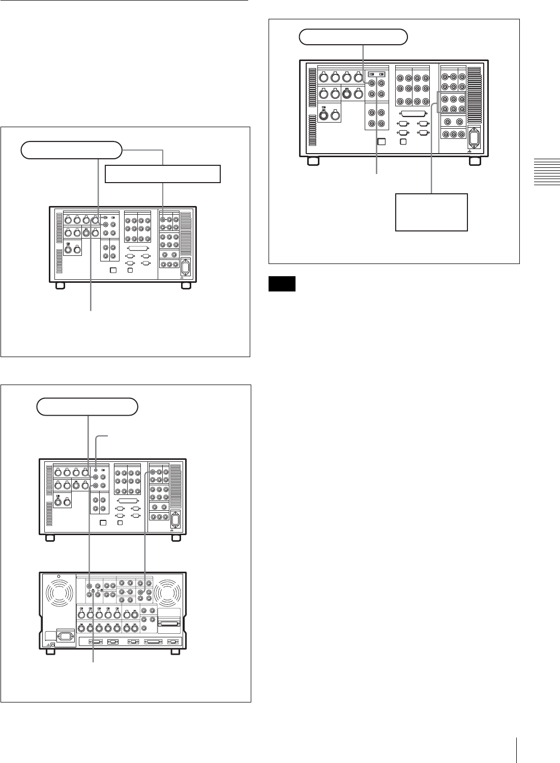
33
3-2 Reference Signals
Chapter 3 Setting Up the VTR
3-2-2 Reference Signal Connections
Make the reference signal connections as follows,
according to your recording or playback requirements.
Reference signal connections
For recording signals from a switcher or signal
generator
For recording signals from a HD VTR
For playback
The following signals can be used as a reference signal.
• HD trilevel SYNC signal of an appropriate field
frequency for external synchronization
• Black burst signal of 525/59.94 Hz
• Black burst signal of 625/50 Hz
Input the signal of the appropriate field frequency for your
system.
Sync signals in 720p mode
Synchronize to an external sync signal when you want to
record or play back 720p signals on this unit (including
editing).
• When the 720/59.94p system is selected:
You can select the following reference signals from
menu item 006 “EXTERNAL REFERENCE select”.
extrn HD: 1080/59.94i tri-level SYNC signal
extrn SD: 525 black burst signal
• When the 720/50p system is selected:
You can select the following reference signals from
menu item 006 “EXTERNAL REFERENCE select”.
extrn HD: 1080/50i tri-level SYNC signal
extrn SD: 625 black burst signal
When you have directly connected the input and output
connectors of two SRW-5000/5500 units, you can also
perform dubbing with the VTR SETUP menu item 005
being set to “input”.
HD SDI INPUTREF. INPUT 1
Reference signal
Switcher or signal generator
SRW-5000/5500a)
75Ω termination switch: ON
a) The figure shows the SRW-5500.
HD SDI OUTPUTHD SDI INPUT
HD SDI INPUT AREF. INPUT 1
REF. INPUT 1
Reference signal
SRW-5000/5500 (Recorder)a)
75Ω termination switch: OFF
HDW-F500 (Player)
75Ω termination switch: ON
a) The figure shows the SRW-5500.
Note
HD SDI OUTPUT
REF. INPUT 1
Reference signal
HD serial input
monitor
SRW-5000/5500a)
75Ω termination switch: ON
a) The figure shows the SRW-5500.
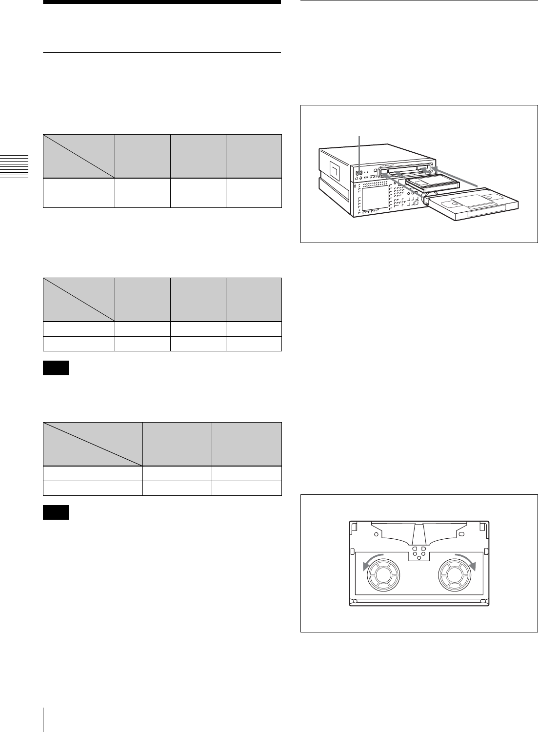
34 3-3 Handling Cassettes
Chapter 3 Setting Up the VTR
3-3 Handling Cassettes
3-3-1 Recommended Cassettes
For recording and playback:
Use 1/2 inch HDCAM-SR cassettes.
The maximum recording time is as shown in the following
table.
For playback only:
Use 1/2 inch HDCAM or Digital Betacam cassettes.
The maximum playback time is as shown in the following
table.
HDCAM cassettes are for playback only on the
SRW-5000. They can be played back and recorded on the
SRW-5500.
Playing back a digital Betacam cassette requires the
Digital Betacam Option (HKSR-5002).
Storage of cassettes
Store your cassettes at room temperature and normal
humidity.
3-3-2 Inserting and Ejecting
Cassettes
Always turn on the VTR before inserting or ejecting
cassettes.
Inserting a cassette
1
Turn the POWER switch to ON.
2
Before inserting a cassette, check the following points:
• There is no slack in the tape.
• An error message does not appear in the menu
display.
• The window of the cassette is facing up.
If there is any slack in the tape, see “Removing slack
in the tape” on page 34.
When inserting an S-size cassette, make sure it is
aligned with the marks on the cassette insertion slot.
The cassette is loaded automatically, and the tape is
wound around the drum.
Removing slack in the tape
Press one of the reels in slightly, then carefully rotate it in
the direction of the arrow until it stops.
HDCAM
SR-cassette
29.97/30 Hz 25 Hz 23.98/24 Hz
S-size cassette 40 minutes 48 minutes 50 minutes
L-size cassette 124 minutes 149 minutes 155 minutes
HDCAM
cassette
29.97/30 Hz 25 Hz 23.98/24 Hz
S-size cassette 40 minutes 48 minutes 50 minutes
L-size cassette 124 minutes 149 minutes 155 minutes
Note
Digital
Betacam cassette
29.97 Hz 25 Hz
S-size cassette 40 minutes 40 minutes
L-size cassette 124 minutes 124 minutes
Note
System
frequency
System
frequency
System
frequency
1
2S-size cassette
L-size cassette
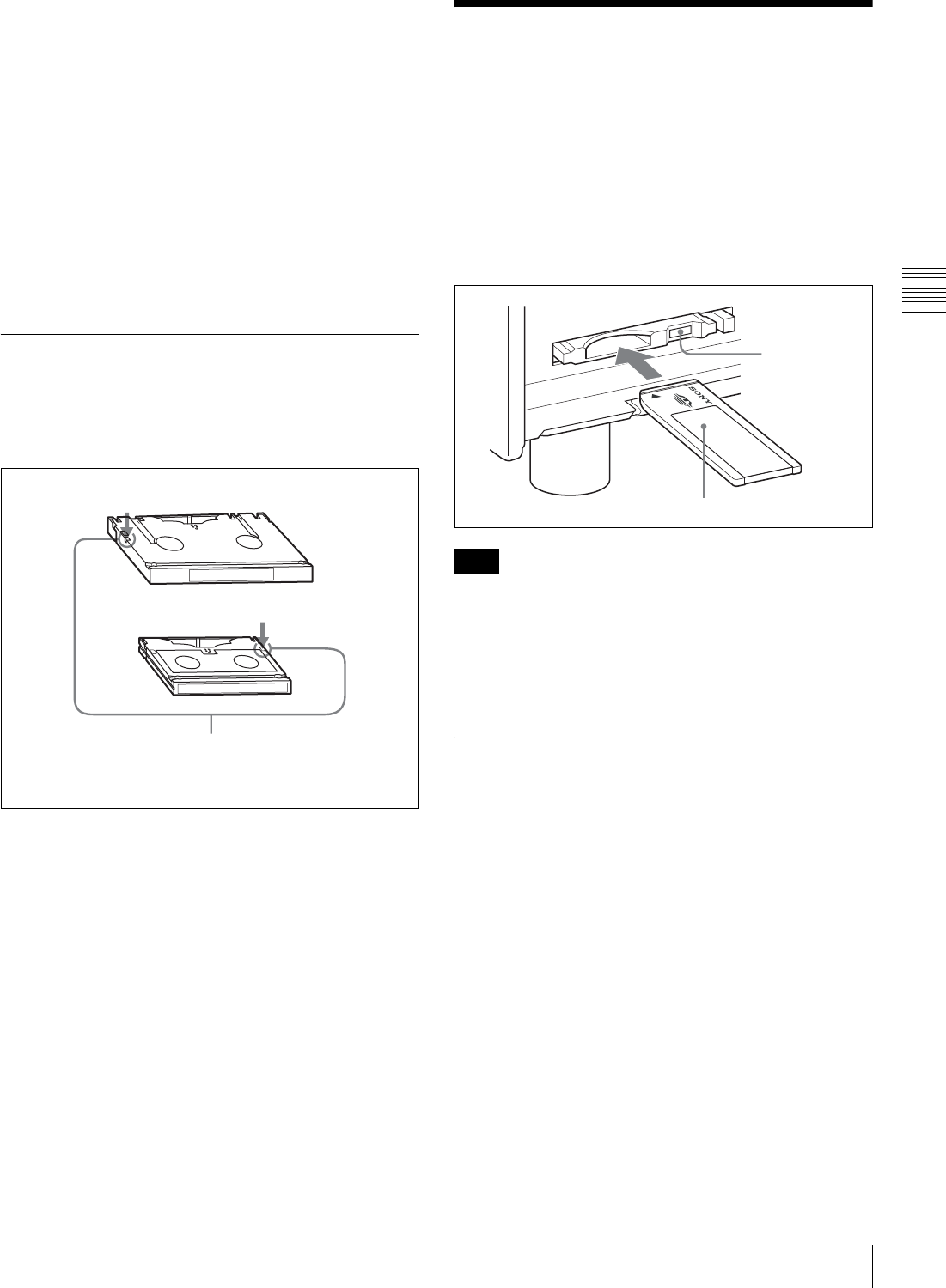
35
3-4 Using a Memory Stick
Chapter 3 Setting Up the VTR
Preventing double cassette inserting
When a cassette is loaded, an orange lock-out bar appears
in the cassette insertion slot to prevent users from
attempting to load another cassette.
Ejecting the cassette
Press the EJECT button.
The tape is unthreaded and the cassette is automatically
ejected. This operation takes a few seconds.
To cancel ejecting a cassette
Press any operation button before the cassette is
completely ejected. The cassette is loaded again and the
operation corresponding to the button you pressed starts.
3-3-3 Preventing Accidental
Erasure
To prevent accidental erasure of material recorded on a
tape, push in the record-protect plug.
When a cassette with this plug pushed in is inserted into
the VTR, the REC INHIBIT indicator on the lower control
panel lights up and recording will not start, even if you
press the REC/EDIT button.
To restore the tape for recording, return the plug to its
original position.
3-4 Using a Memory Stick
When a Memory Stick is inserted in the VTR, the file data
can be stored on the Memory Stick, which enables you to
share data among VTRs.
Inserting a Memory Stick
Insert a Memory Stick with the label side up into the
Memory Stick slot until it clicks and the access lamp
lights in red.
Never insert/remove a Memory Stick during access to
data.
To remove a Memory Stick
Push the eject button on the Memory Stick PC card
adaptor, and pull the Memory Stick out.
3-4-1 Notes on Memory Stick
On Memory Stick
Memory Stick is a new compact, portable and versatile IC
recording medium with a data capacity that exceeds that of
a floppy disk. Memory Stick is specially designed for
exchanging and sharing digital data among Memory Stick
compatible products. Because it is removable, Memory
Stick can also be used for external data storage.
Types of Memory Stick
There are two types of Memory Stick: MagicGate
Memory Stick that is equipped with the MagicGate
copyright protection technology and general Memory
Stick. Use the general type of Memory Stick (8MB,
16MB, 32MB, 64MB, 128MB) with this unit.
L-size cassette
S-size cassette
Push in the record-protect plug. (ON)
To restore the tape for recording, return the plug to its
original position. (OFF)
Note
Eject button
Memory Stick
Label side up
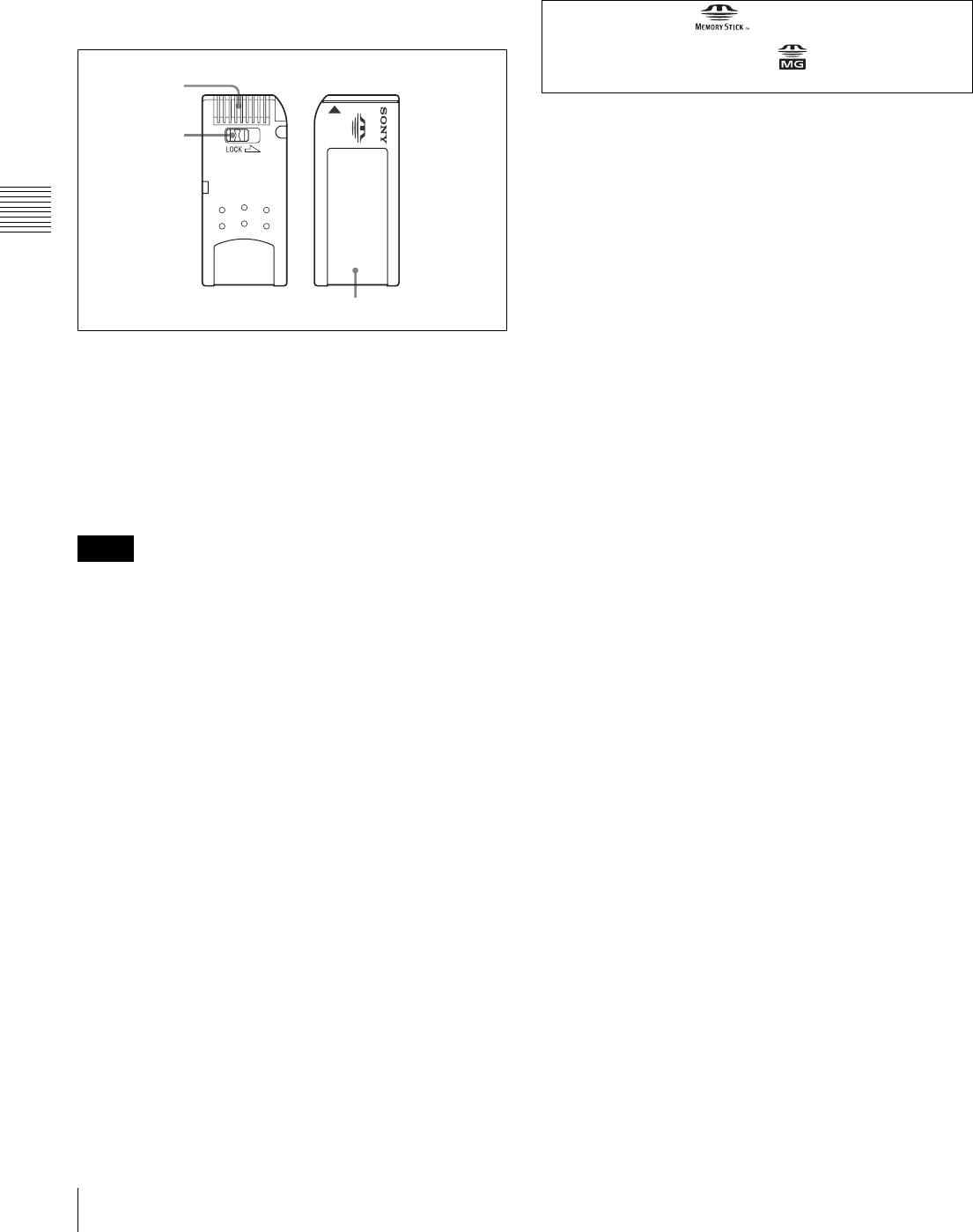
36 3-4 Using a Memory Stick
Chapter 3 Setting Up the VTR
On MagicGate
MagicGate is copyright-protection technology that uses
encryption technology.
Before using a Memory Stick
• You cannot record or erase data when the write-protect
tab on the Memory Stick is set to LOCK.
• We recommend backing up important data.
• Image data may be damaged in the following cases:
- If you remove the Memory Stick, or turn the power
off when the access lamp is lit or flashing
- If you use a Memory Stick near static electricity or a
magnetic field
• Prevent metallic objects or your finger from coming into
contact with the terminal of the connecting section.
• Do not attach any material other than the supplied label
to the label space.
• Attach the label at the prescribed labeling position.
Make sure the label is attached at the labeling position
properly.
• Do not bend, drop, or apply strong shock to a Memory
Stick.
• Do not disassemble or modify a Memory Stick.
• Do not let the Memory Stick get wet.
• Do not use or keep a Memory Stick in locations that are:
- Extremely hot such as in a car parked in the sun
- Under direct sunlight
- Very humid or subject to corrosive gases
• When you carry or store a Memory Stick, keep it in its
case.
• The PCMCIA memory card supplied with the HDW-
500/F500 and the HDW-2000 series cannot be used with
the SRW-5000/5500.
During access to data
While data are being read from or written to the Memory
Stick, do not shake this unit or subject it to shock. Do not
turn off the power of the unit or remove the Memory
Stick. This may damage the data.
Notes
Terminal
Write-protect
tab
Labeling position
Memory Stick and are the trademarks of Sony
Corporation.
MagicGate Memory Stick and are the trademarks of
Sony Corporation.
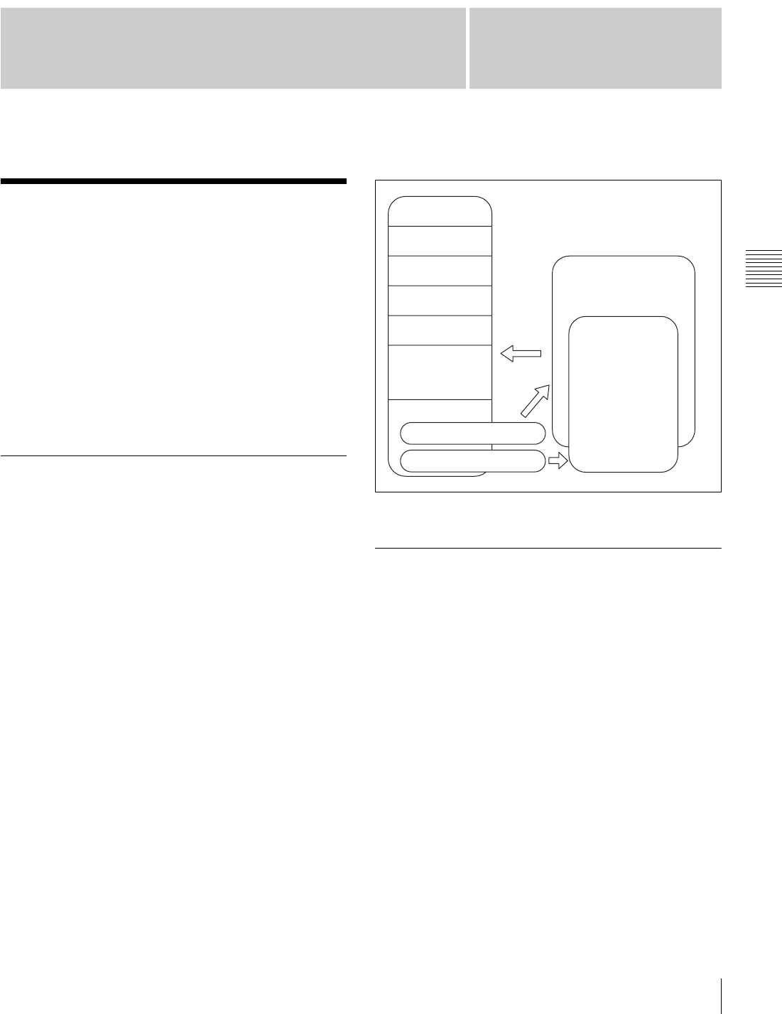
37
4-1 Registering and Storing Menu Settings
Chapter
Chapter 4 Menu Settings
4
Menu Settings
4-1 Registering and
Storing Menu Settings
The operating conditions of the VTR are set using the
menu operation section on the lower control panel.
Menu items are divided among eight different menus
(HOME, TC, VIDEO, AUDIO, CUE, PF1, PF2, SET UP).
You can register any frequently used items to the HOME,
TC, VIDEO, AUDIO, PF1, and PF2 menu screens. By
registering the necessary items in advance, setting
operations are made quicker. The contents of the eight
VTR memory banks can, in turn, be stored on a memory
stick for later recall.
4-1-1 Menu Configuration
This VTR has two kinds of menus.
VTR SETUP menu list
This menu contains items that specify the initial operating
conditions of the VTR. You can change these settings
directly without registering the items to the function
buttons.
Press the [F6] (VTR SETUP) button in the SET UP menu
to display this menu.
For details on setting operating conditions of the VTR, see
“4-7-1 VTR SETUP Menu” on page 98.
PF ASSIGN menu list
This is a list of menu items which can be registered to the
HOME, TC, VIDEO, AUDIO, PF1 and PF2 menu screens
as well as the screen that is displayed by pressing the ALT
button (the ALT screen). This includes all VTR SETUP
menu item.
Press the [F4] (PF ASSIGN) button in the SET UP menu to
display this menu.
For details on registering items, see “4-1-3 Registering
Items to the VTR SETUP Menu” on page 38.
The menu configuration of the VTR is shown in the
following figure.
PF button assignment allows you to assign the same item
also to a different menu screen or button.
4-1-2 Changing Menu Settings
To activate the HOME, TC, VIDEO, AUDIO, CUE, PF1,
PF2, or SET UP menu, press the respective menu button.
Menu items are assigned to function buttons ([F1] to [F10])
in each menu. When two items are registered to the same
function button, you can display the second item by
pressing the ALT button.
The example below describes the procedure for changing
the setting specified by the ALT/[F6] (CHARA SUPER)
button in the TC menu.
HOME menu
TC menu
VIDEO menu
AUDIO menu
PF1 menu
PF2 menu
CUE menu
SETUP menu
[F4] (PF ASSIGN) button
[F6] (VTR SETUP) button
Registration
PF button 1&2
ASSIGN menu
VTR SETUP
menu list
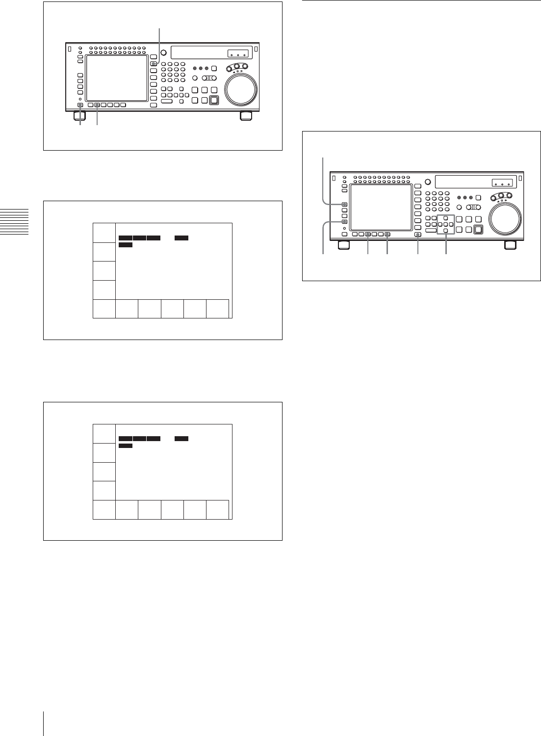
38 4-1 Registering and Storing Menu Settings
Chapter 4 Menu Settings
1
Press the TC button.
The first page of the TC menu appears in the display.
2
Press the ALT button.
The second page of the TC menu appears in the
display.
To return to the first page
Press the ALT button again.
3
Press the [F6] (CHARA SUPER) button to change the
setting.
Each time the button is pressed, the setting changes.
4-1-3 Registering Items to the VTR
SETUP Menu
You can register 120 menu items including those displayed
by pressing the ALT button in the HOME, TC, VIDEO,
AUDIO, PF1, and PF2 menus. By registering frequently
used menu items, the settings can be carried out together.
Registering items
1
Press the SET UP button.
The SET UP menu appears in the display.
2
Press the [F4] (PF ASSIGN) button.
The PF ASSIGN menu appears in the display.
3
Press the [F1] (PAGE) button to select the menu where
you wish to register an item.
The selected menu appears and the items currently
registered to the menu appear in the middle of the
display.
If the function button assignments are other than the
default, the [F3] (PAGE DEF.) button is valid.
To return all function buttons to the default
settings
Press the [F3] (PAGE DEF.) button.
4
Press the cursor R or r button to move the cursor (B) to
the function button where the item is to be registered.
The selected function button is highlighted and the
current setting is displayed.
2 3
1
TIMER
SEL
TC LTC
TGA
INTRP DF
PLAY LOCK
TIMER
RESET
TIMER
SET
TIMER
HOLD
TCR
SEL
LTC
TCG
MODE
prst
RUN
MODE
free
DF/NDF
DF
TC2
SEL
OFF
REGENE
SOURCE
int-L
00
H
02
M
39
S
18
F
AIN --:--:--:-- AOUT --:--:--:--
IN --:--:--:-- OUT --:--:--:--
F2
TAPE
TIMER
24H LTC
TCA
INTRP DF F2
PLAY LOCK
POPSET
MENU
-
TCCONY
MENU
-
PDTC
DIEP
off
PD
CHARA
off
CHARA
M-POS
1
CHARA
V-POS
22
CHARA
SUPER
ON
00
H
02
M
39
S
18
F
AIN --:--:--:-- AOUT --:--:--:--
IN --:--:--:-- OUT --:--:--:--
6 8 1
2
3
4,5
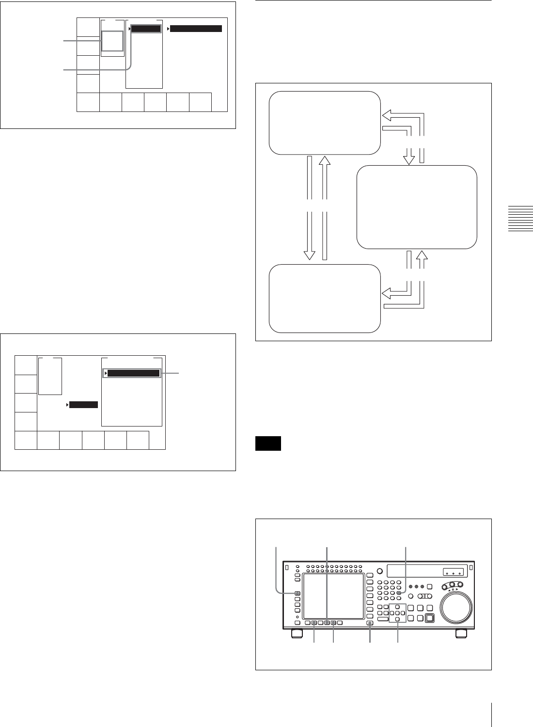
39
4-1 Registering and Storing Menu Settings
Chapter 4 Menu Settings
To unregister the selected item
Press the [F6] (BLANK) button.
When a function button with other than the default
assignment is selected, the [F4] (KEY DEF.) button is
valid.
To return the selected function button to its default
setting, press the [F4] (KEY DEF.) button.
5
Press the cursor t button to move the cursor (B) to
the menu list (PF ASSIGN menu), then press the
cursor R or r button to move the cursor to the menu
item to be registered.
To scroll the menu faster
Press the cursor R or r button while holding down the
SFT button.
6
Press the [F7] (PASTE) button to register the item.
The new item is registered to the function button.
7
Repeat steps 3 to 6 to register more items.
To cancel the registration of all new items
Press the [F9] (CANCEL) button.
8
Press the [F10] (SAVE/EXIT) button to save the newly
registered items.
The registration is completed and the SET UP menu
appears in the display again.
4-1-4 VTR Memory Bank Function
Eight VTR memory banks are provided for storing up to
eight sets of menu settings.
The contents of all eight VTR memory banks can be stored
on a memory stick.
For details on memory stick use, see see “4-1-5 Memory
Stick Operations” on page 41.
For details on adding titles to the contents of the VTR
memory bank, see “4-1-6 Adding Titles to the Data” on
page 46.
The contents of SETUP BANKF cannot be changed.
Storing the current VTR menu settings to a
VTR memory bank
PAGE
PAGE
DEF.
KEY
DEF.
PASTE CANCEL SAVE/
EXIT
BLANK
ALT+HOME
F1 : 001
F2 :
F3 : K17
F4 :
F5 :
F6 : 302
F7 : K18
F8 : K25
F9 : K44
-
F1
PAE
READ
off
VTR SETUP MENU
001:PRE READ
002:REC INH
003:REC INH ARE
005:SERVO REF
006:EXT REF SEL
007:SYNC PLAY
008:LOCAL ENA
009:LOCAL NAP
017:PB/EE STATE
Current setting
Function button
where item is to
be registered
PAGE
PAGE
DEF.
KEY
DEF.
PASTE CANCEL SAVE/
EXIT
BLANK
ALT+HOME
F1 : 001
F2 :
F3 : K17
F4 :
F5 :
F6 : 302
F7 : K18
F8 : K25
F9 : K44
F7
DMC
VTR SETUP MENU -
632:JUMP TC sel
705:YAOO
706:MASTER(HD)
708:Y LEVEL(HD)
710:PB LVL(HD)
711:PR LVL(HD)
712:SETUP(HD)
713:SYNC(HD)
714:FINE(HD)
-
Item to be
registered
Note
Current menu settings in the
VTR (CURRENT SETUP).
These settings are stored
outside the VTR memory
banks even when the power
is off. Storing/recalling
Storing/recalling
VTR memory banks (SETUP
BANK1 to 8 and F). SETUP
BANK F contains the factory-
set menu settings. By calling up
SETUP BANK F, you can
restore all menu items to their
factory settings.
Memory stick (SETUP BANK
0 to 8). The stick stores
setting data in same way as
the VTR memory banks.
These contents can be later
called up in the VTR.
Storing/recalling
4 6 1
32
5
CLR button
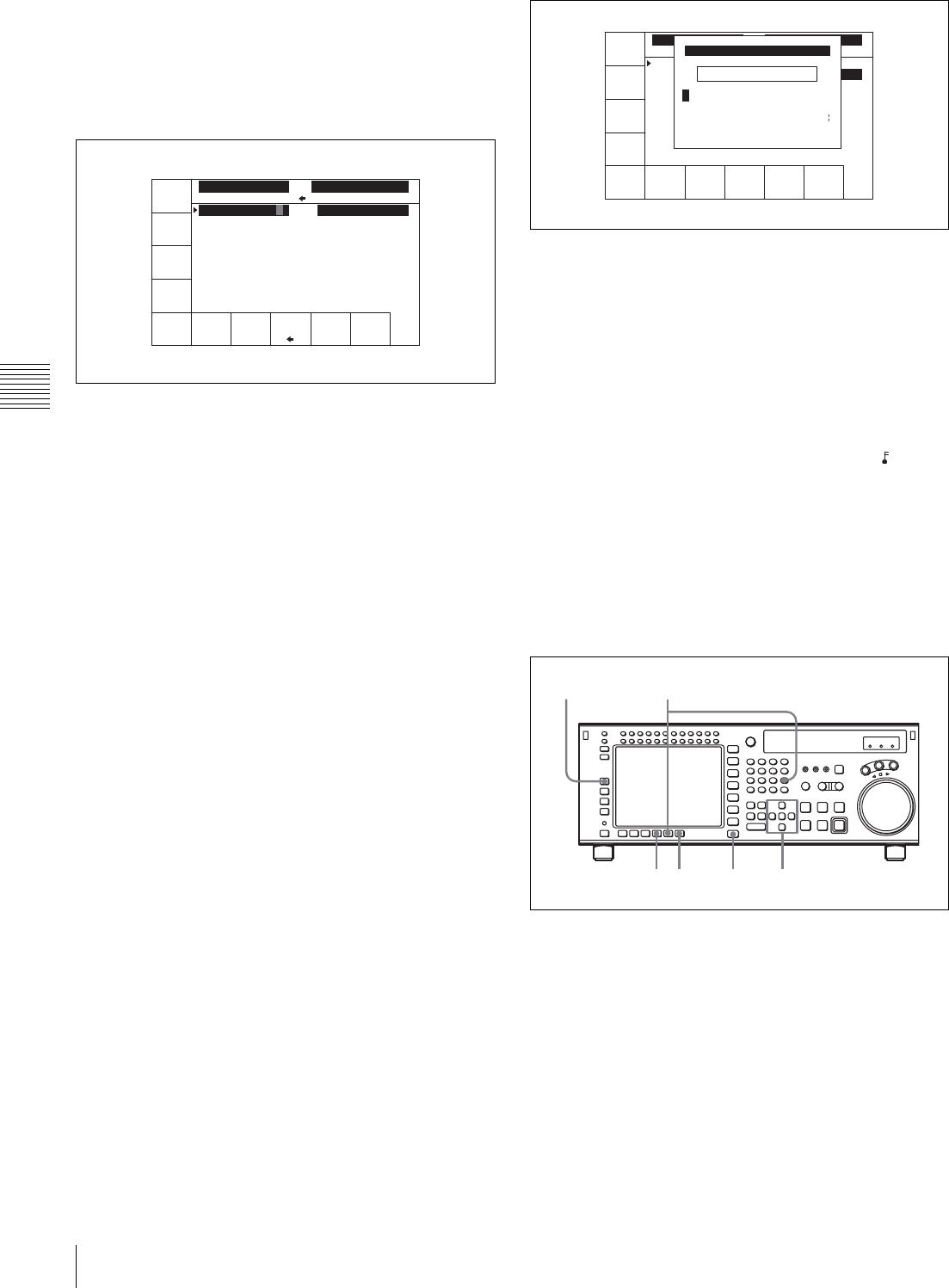
40 4-1 Registering and Storing Menu Settings
Chapter 4 Menu Settings
1
Press the SET UP button.
The SET UP menu appears in the display.
2
Press the [F1] (VTR BANK) button.
The VTR BANK menu appears in the display.
3
Press the [F8] (DIRECTION) button to select the <
direction.
4
Press the cursor T button to move the cursor (B) to
CURRENT SETUP[C], then press the [F6] (EDIT
TITLE) button to add a title to the current menu
settings of the VTR.
For details, see “4-1-6 Adding Titles to the Data” on
page 46.
5
Press the cursor t button to move the cursor (B) to
SETUP BANK, then press the cursor R or r button to
move the flashing cursor bar to the number of the VTR
memory bank to be used for saving the current menu
settings.
The flashing cursor bar indicates the storage
destination.
6
Press the [F9] (COPY) button.
A message appears in the display asking you to
confirm the operation.
To cancel the storage operation
Press the CLR button.
7
Press the [F9] (COPY) button while holding down the
SFT button.
The current menu settings are stored to the VTR
memory bank.
To add or change a title for VTR settings after
storing them to the VTR memory bank
Move the cursor (B) to the number of the VTR
memory bank where the settings are stored, then press
the [F6] (EDIT TITLE) button.
For more information, see “4-1-6 Adding Titles to the
Data” on page 46.
Recovering previous settings after new settings
have been saved
Press the [F2] (UNDO) button to recover the previous
settings.
Preventing accidental erasure after saving settings
Move the cursor to the memory bank to be protected
and press ALT/[F2] (PROTECT) buttons. A will
appear next to the selected bank.
8
Press the [F10] (EXIT) button.
The SET UP menu appears again.
Recalling menu settings from a VTR
memory bank
1
Press the SET UP button.
The SET UP menu appears in the display.
2
Press the [F1] (VTR BANK) button.
The VTR BANK menu appears in the display.
UNDO
DIREC-
TION
COPY EXITEDIT
TITLE
VTR BANK
SETUP BANK 1
1 (Preset)
2 (Preset)
3 (Preset)
4 (Preset)
5 (Preset)
6 (Preset)
7 (Preset)
8 (Preset)
1F (Preset)
VTR BANK
CURRENT SETUP
AAA C
SPACE SET
LETTER
CANCEL SAVE/
EXIT
BACK
SPACE
VTR BANK
SETUP BANK 1
1 (Preset)
2 (Preset)
3 (Preset)
4 (Preset)
5 (Preset)
6 (Preset)
7 (Preset)
8 (Untitled)
1F (Preset)
VTR BANK
CURRENT SETUP
(Preset)
(Preset)_
ABCDEFGHIJKLMNOPQRSTUVWXYZ
abcdefghjiklmnopqrstuvwxyz
0123456789[]()<>@+-*=!?:;
CURRENT SETUP TITLE EDIT
$#%&,."\^_'/~ {} HD1D2CAM
'
3 7 1
52
4
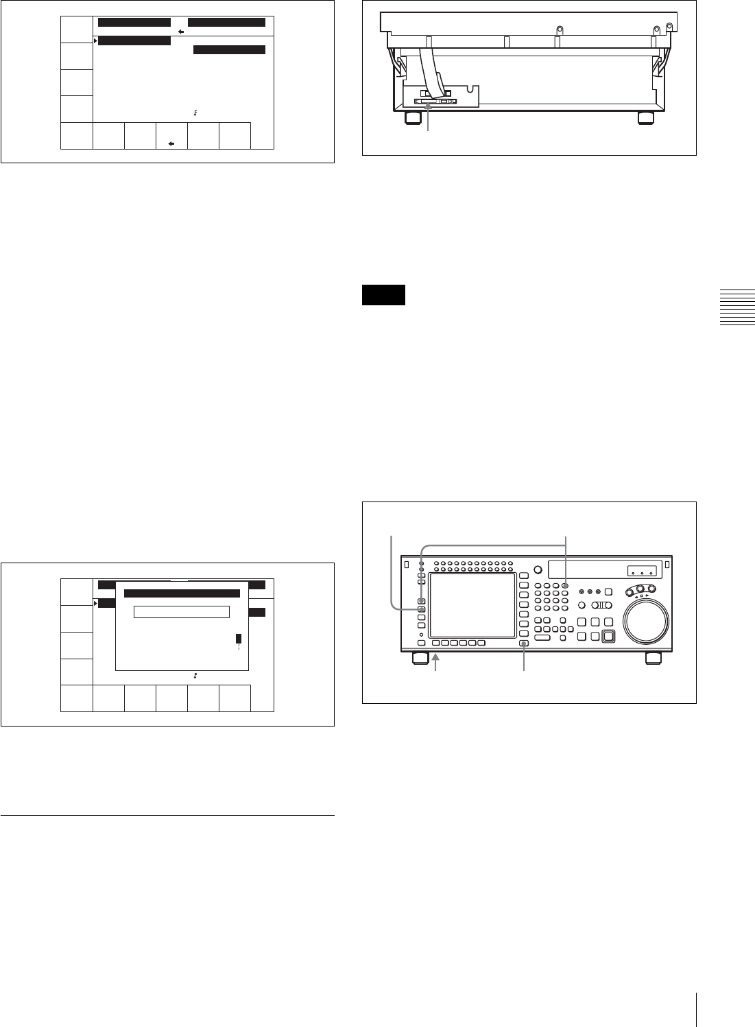
41
4-1 Registering and Storing Menu Settings
Chapter 4 Menu Settings
3
Press the [F8] (DIRECTION) button to select the <
direction.
The left cursor bar flashes.
4
Press the cursor R or r button to move the cursor (B) to
the number of the VTR memory bank to be recalled.
5
Press the [F9] (COPY) button.
A message asking you to confirm the operation
appears in the display.
To cancel the recalling operation
Press the CLR button.
6
Press the [F9] (COPY) button while holding down the
SFT button.
The menu settings are recalled from the selected VTR
memory bank.
When the recalling process has been completed, the
title of the VTR bank appears under CURRENT
SETUP in the display.
7
Press the [F10] (SAVE/EXIT) button.
The SET UP menu appears again.
4-1-5 Memory Stick Operations
You can store menu settings in the VTR memory banks
and cue point data to a memory stick for recall later.
To eject the memory stick
Raise up the lower control panel, and press the button on
the right side of the insertion slot.
For details of opening and closing the control panel, refer
to the Maintenance Manual.
• When inserting a memory stick, press it firmly in as far
as it will go. The stick recognition status is shown on the
MEMCARD menu screen. If not inserted properly,
reinsert it.
• While data is being read from or written to the memory
stick, the status appears on the screen. During these
operations, do not remove the memory stick.
Formatting a memory stick
Memory sticks must be formatted before you can use them.
1
Insert the memory stick.
2
Press the SET UP button.
The SET UP menu appears in the display.
3
Press the [F2] (MEMORY CARD) button.
The MEMCARD menu appears in the display.
UNDO
DIREC-
TION
COPY EXITEDIT
TITLE
VTR BANK
SETUP BANK 2
1 (Preset)
2 (Preset)
3 (Preset)
4 (Preset)
5 (Preset)
6 (Preset)
7 (Preset)
8 (Untitled)
F (Preset)
VTR BANK
CURRENT SETUP
(Preset) C
SPACE CANCEL SAVE/
EXIT
BACK
SPACE
VTR BANK
SETUP BANK 1
1 (Preset)
2 (Preset)
3 (Preset)
4 (Preset)
5 (Preset)
6 (Preset)
7 (Preset)
8 (Untitled)
F (Preset)
VTR BANK
CURRENT SETUP
(Preset)
(Preset)_
ABCDEFGHIJKLMNOPQRSTUVWXYZ
abcdefghjiklmnopqrstuvwxyz
0123456789[]()<>@+-*=!?:;
CURRENT SETUP TITLE EDIT
$#%&,."\^_'/~ {} HD1D2CAM
'
Notes
Memory stick insertion slot
4,5,6
12
3
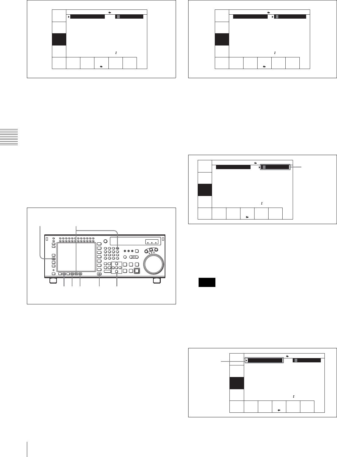
42 4-1 Registering and Storing Menu Settings
Chapter 4 Menu Settings
4
Press the [F1] (FORMAT CARD) button.
A message asking you to confirm the operation
appears in the display.
To cancel formatting
Press the CLR button while the confirmation message
appears in the display.
5
Press the [F1] (FORMAT CARD) button while
holding down the SFT button.
The VTR starts formatting the memory stick.
Storing the contents of the VTR memory
banks to a memory stick
1
Press the SET UP button.
The SET UP menu appears in the display.
2
Press the [F2] (MEMORY CARD) button.
The MEMCARD menu appears in the display.
3
Press the [F8] (DIRECTION) button to select the <
direction.
The left cursor bar flashes.
4
Move the cursor B to the VTR side using the cursor t
button and use the cursor R or r button to move the
cursor bar to the memory bank where the data is to be
saved.
To store the current VTR menu settings
Move the cursor (B) to the [C] (CURRENT SETUP)
position.
To store all VTR memory banks
Press the [F7] (SELECT ALL) button.
If there are protected items at the destination end, it is
not possible to select the [F7] (SELECT ALL) button.
5
Move the cursor (B) to the memory stick side using the
cursor T button, and use the cursor R or r button to
move the cursor to the bank number (memory stick
side) where the data is to be saved.
FORMAT
CARD
UNDO
SHOW
SETUP
SHOW
CUESET
SELECT
ALL
DIREC-
TION
COPY EXITEDIT
TITLE
CARD BANK 0
(BASEBALL) 0
(Preset) 1
(Preset) 2
(Preset) 3
(Preset) 4
(Preset) 5
(Preset) 6
(Preset) 7
(Preset) 8
CURRENT SETUP
C FOOTBALL
1 (Preset)
2 (Preset)
3 (Preset)
4 (Preset)
5 (Preset)
6 (Preset)
7 (Preset)
8 (Preset)
F (Preset)
36 9 1
7,82
4,5
Note
FORMAT
CARD
UNDO
SHOW
SETUP
SHOW
CUESET
SELECT
ALL
DIREC-
TION
COPY EXITEDIT
TITLE
CURRENT SETUP
C FOOTBALL
1 (Preset)
2 (Preset)
3 (Preset)
4 (Preset)
5 (Preset)
6 (Preset)
7 (Preset)
8 (Preset)
F (Preset)
CARD BANK 0
(BASEBALL) 0
(Preset) 1
(Preset) 2
(Preset) 3
(Preset) 4
(Preset) 5
(Preset) 6
(Preset) 7
(Preset) 8
FORMAT
CARD
UNDO
SHOW
SETUP
SHOW
CUESET
SELECT
ALL
DIREC-
TION
COPY EXITEDIT
TITLE
CARD BANK 0
(BASEBALL) 0
(Preset) 1
(Preset) 2
(Preset) 3
(Preset) 4
(Preset) 5
(Preset) 6
(Preset) 7
(Preset) 8
CURRENT SETUP
C FOOTBALL
1 (Preset)
2 (Preset)
3 (Preset)
4 (Preset)
5 (Preset)
6 (Preset)
7 (Preset)
8 (Preset)
F (Preset)
Saved data
FORMAT
CARD
UNDO
SHOW
SETUP
SHOW
CUESET
SELECT
ALL
DIREC-
TION
COPY EXITEDIT
TITLE
CARD BANK 0
(BASEBALL) 0
(Preset) 1
(Preset) 2
(Preset) 3
(Preset) 4
(Preset) 5
(Preset) 6
(Preset) 7
(Preset) 8
CURRENT SETUP
C FOOTBALL
1 (Preset)
2 (Preset)
3 (Preset)
4 (Preset)
5 (Preset)
6 (Preset)
7 (Preset)
8 (Preset)
F (Preset)
Destination
(flashing)
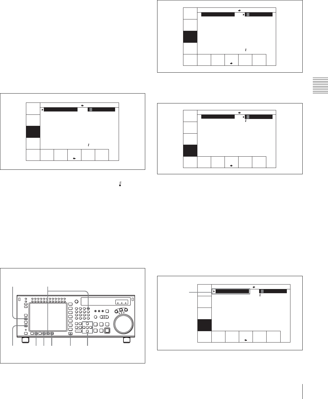
43
4-1 Registering and Storing Menu Settings
Chapter 4 Menu Settings
The flashing cursor bar indicates the storage
destination.
6
To change the title of the bank, press the [F6] (EDIT
TITLE) button.
For details, see “4-1-6 Adding Titles to the Data” on
page 46.
7
Press the [F9] (COPY) button.
A message asking you to confirm the operation
appears in the display.
8
Press the [F9] (COPY) button while holding down the
SFT button.
Storage begins.
After the storage is complete, the title of the VTR
memory bank appears on the memory stick side.
Preventing accidental erasure after saving settings
Press ALT/[F2] (PROTECT) buttons and a symbol
will appear to the right of the memory card bank
number.
9
Press the [F10] (EXIT) button.
The SET UP menu appears again.
Storing cue point lists to a memory stick
You can store up to 8 pages of cue point lists to a memory
stick along with titles.
1
Press the SET UP button.
The SET UP menu appears in the display.
2
Press the [F2] (MEMORY CARD) button.
The MEMORY CARD menu appears in the display.
3
Press the [F4] (SHOW CUESET) button.
The display for storing cue point lists appears.
To return to the MEMORY CARD menu
Press the [F3] (SHOW SETUP) button.
4
Press the [F8] (DIRECTION) button to select the <
direction.
The left cursor bar flashes.
5
Use the cursor T button to move the cursor (B) to
CUE POINT SET side, then press the cursor R or r
button to move the cursor bar to the number of the
memory bank in the memory stick where you want to
store the cue point list.
6
Press the [F9] (COPY) button.
FORMAT
CARD
UNDO
SHOW
SETUP
SHOW
CUESET
SELECT
ALL
DIREC-
TION
COPY EXITEDIT
TITLE
CARD BANK 0
FOOTBALL 0
(Preset) 1
(Preset) 2
(Preset) 3
(Preset) 4
(Preset) 5
(Preset) 6
(Preset) 7
(Preset) 8
CURRENT SETUP
C FOOTBALL
1 (Preset)
2 (Preset)
3 (Preset)
4 (Preset)
5 (Preset)
6 (Preset)
7 (Preset)
8 (Preset)
F (Preset)
48 9,10 1
35
6,72
FORMAT
CARD
UNDO
SHOW
SETUP
SHOW
CUESET
SELECT
ALL
DIREC-
TION
COPY EXITEDIT
TITLE
CARD BANK 0
(BASEBALL) 0
(Preset) 1
(Preset) 2
(Preset) 3
(Preset) 4
(Preset) 5
(Preset) 6
(Preset) 7
(Preset) 8
CURRENT SETUP
C FOOTBALL
1 (Preset)
2 (Preset)
3 (Preset)
4 (Preset)
5 (Preset)
6 (Preset)
7 (Preset)
8 (Preset)
F (Preset)
FORMAT
CARD
UNDO
SHOW
SETUP
SHOW
CUESET
SELECT
ALL
DIREC-
TION
COPY EXITEDIT
TITLE
CUE POINT SET 1
MUSIC 1
(Blank) 2
(Blank) 3
(Blank) 4
(Blank) 5
(Blank) 6
(Blank) 7
(Blank) 8
CURRENT CUE SET
C MOVIE
F (Blank)
FORMAT
CARD
UNDO
SHOW
SETUP
SHOW
CUESET
SELECT
ALL
DIREC-
TION
COPY EXITEDIT
TITLE
CUE POINT SET 1
MUSIC 1
(Blank) 2
(Blank) 3
(Blank) 4
(Blank) 5
(Blank) 6
(Blank) 7
(Blank) 8
CURRENT CUE SET
C MOVIE
F (Blank)
Destination
(flashing)
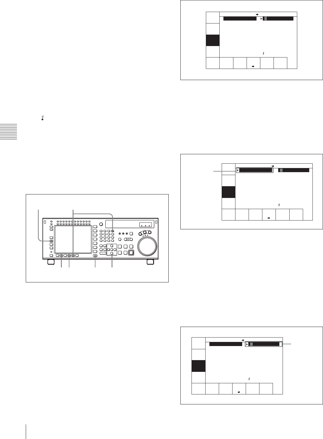
44 4-1 Registering and Storing Menu Settings
Chapter 4 Menu Settings
A message asking you to confirm the operation
appears in the display.
7
Press the [F9] (COPY) button while holding down the
SFT button.
The VTR stores the cue point list to the memory stick.
8
Press the [F6] (EDIT TITLE) button to add a title to the
cue point list.
For details, see “4-1-6 Adding Titles to the Data” on
page 46.
Preventing accidental erasure after saving settings
Move the cursor (B) to the cue point set number you
wish to save and press ALT/[F2] (PROTECT) buttons.
A symbol will appear to the right of the cue point set
number.
9
Press the [F10] (EXIT) button.
The SET UP menu appears again.
Recalling the contents of a memory stick
The contents stored in a memory stick can be recalled to
the current VTR memory bank.
1
Press the SET UP button.
The SET UP menu appears in the display.
2
Press the [F2] (MEMORY CARD) button.
The MEMORY CARD menu appears in the display.
3
Press the [F8] (DIRECTION) button to select the ,
direction.
The right cursor bar flashes.
4
Move the cursor (B) to the memory stick side using the
cursor T button and use the cursor R or r buttons to
place the cursor bar by the memory bank where the
settings were saved.
5
To change the title of the memory bank, press the [F6]
(EDIT TITLE) button.
The title can also be changed after the settings are
recalled.
For details, see “4-1-6 Adding Titles to the Data” on
page 46.
6
Press the cursor t button to move the cursor (B) to
the VTR side, then press the cursor R or r button to
move the cursor to the VTR memory bank number
where the recalled data are to be stored.
35 1 4,6
2 7,8
FORMAT
CARD
UNDO
SHOW
SETUP
SHOW
CUESET
SELECT
ALL
DIREC-
TION
COPY EXITEDIT
TITLE
CURRENT SETUP
C FOOTBALL
1 (Preset)
2 (Preset)
3 (Preset)
4 (Preset)
5 (Preset)
6 (Preset)
7 (Preset)
8 (Preset)
F (Preset)
CARD BANK 0
(BASEBALL) 0
(Preset) 1
(Preset) 2
(Preset) 3
(Preset) 4
(Preset) 5
(Preset) 6
(Preset) 7
(Preset) 8
Saved data
FORMAT
CARD
UNDO
SHOW
SETUP
SHOW
CUESET
SELECT
ALL
DIREC-
TION
COPY EXITEDIT
TITLE
CURRENT SETUP
C FOOTBALL
1 (Preset)
2 (Preset)
3 (Preset)
4 (Preset)
5 (Preset)
6 (Preset)
7 (Preset)
8 (Preset)
F (Preset)
CARD BANK 0
(BASEBALL) 0
(Preset) 1
(Preset) 2
(Preset) 3
(Preset) 4
(Preset) 5
(Preset) 6
(Preset) 7
(Preset) 8
Destination
(flashing)
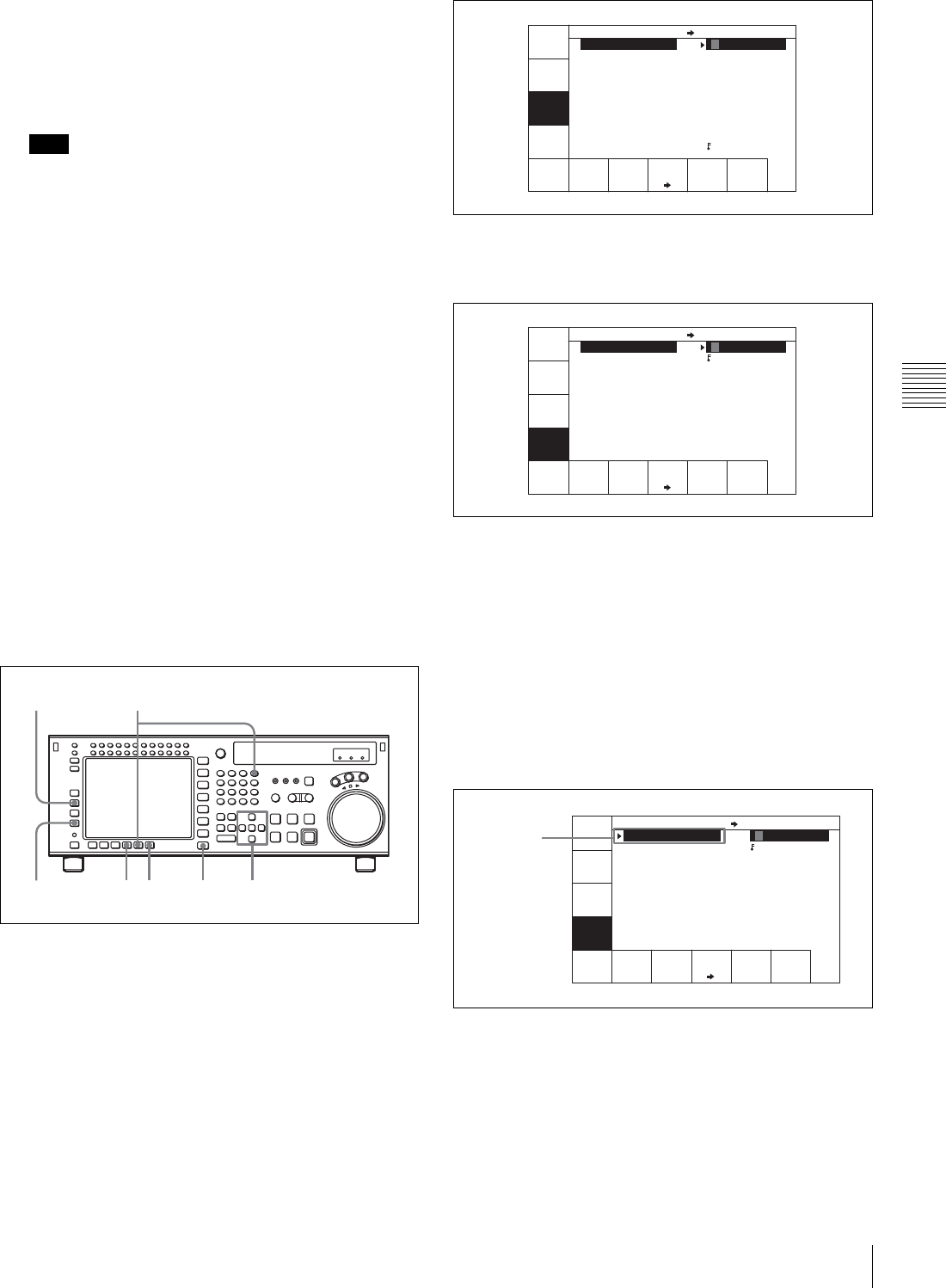
45
4-1 Registering and Storing Menu Settings
Chapter 4 Menu Settings
To change the current VTR menu settings
Move the cursor (B) to [C] (CURRENT SETUP).
To replace all VTR memory bank contents with
memory stick data
Press the [F7] (SELECT ALL) button.
Note
If there are protected items at the destination end, it is
not possible to select the [F7] (SELECT ALL) button.
7
Press the [F9] (COPY) button.
A message asking you to confirm the operation
appears in the display.
8
Press the [F9] (COPY) button while holding down the
SFT button.
The VTR recalls the contents of the memory stick.
After the recalling process is complete, the title of the
memory bank of the memory stick appears under the
VTR indication.
9
Press the [F10] (EXIT) button.
The SET UP menu appears again.
Recalling a cue point list from a memory
stick
Recalling a cue point list from a memory stick replaces the
current VTR cue point list with the recalled data.
1
Press the SET UP button.
The SET UP menu appears in the display.
2
Press the [F2] (MEMORY CARD) button.
The MEMORY CARD menu appears in the display.
3
Press the [F4] (SHOW CUESET) button.
The menu for storing cue point lists appears.
To return to the MEMORY CARD menu
Press the [F3] (SHOW SETUP) button again.
4
Press the [F8] (DIRECTION) button to select the ,
direction.
The right cursor bar flashes.
5
Use the cursor T button to move the cursor (B) to the
CUE POINT SET side, then press the cursor R or r
button to move the cursor bar to the number of the
memory bank in the memory stick.
6
Press the [F9] (COPY) button.
A message asking you to confirm the operation
appears in the display.
7
Press the [F9] (COPY) button while holding down the
SFT button.
48 1
35
6,72
FORMAT
CARD
UNDO
SHOW
SETUP
SHOW
CUESET
SELECT
ALL
DIREC-
TION
COPY EXITEDIT
TITLE
CARD BANK 0
(BASEBALL) 0
(Preset) 1
(Preset) 2
(Preset) 3
(Preset) 4
(Preset) 5
(Preset) 6
(Preset) 7
(Preset) 8
CURRENT SETUP
C FOOTBALL
1 (Preset)
2 (Preset)
3 (Preset)
4 (Preset)
5 (Preset)
6 (Preset)
7 (Preset)
8 (Preset)
F (Preset)
FORMAT
CARD
UNDO
SHOW
SETUP
SHOW
CUESET
SELECT
ALL
DIREC-
TION
COPY EXITEDIT
TITLE
CUE POINT SET 1
MUSIC 1
(Blank) 2
(Blank) 3
(Blank) 4
(Blank) 5
(Blank) 6
(Blank) 7
(Blank) 8
CURRENT CUE SET
C MOVIE
F (Blank)
FORMAT
CARD
UNDO
SHOW
SETUP
SHOW
CUESET
SELECT
ALL
DIREC-
TION
COPY EXITEDIT
TITLE
CUE POINT SET 1
MUSIC 1
(Blank) 2
(Blank) 3
(Blank) 4
(Blank) 5
(Blank) 6
(Blank) 7
(Blank) 8
CURRENT CUE SET
C MOVIE
F (Blank)
Saved data
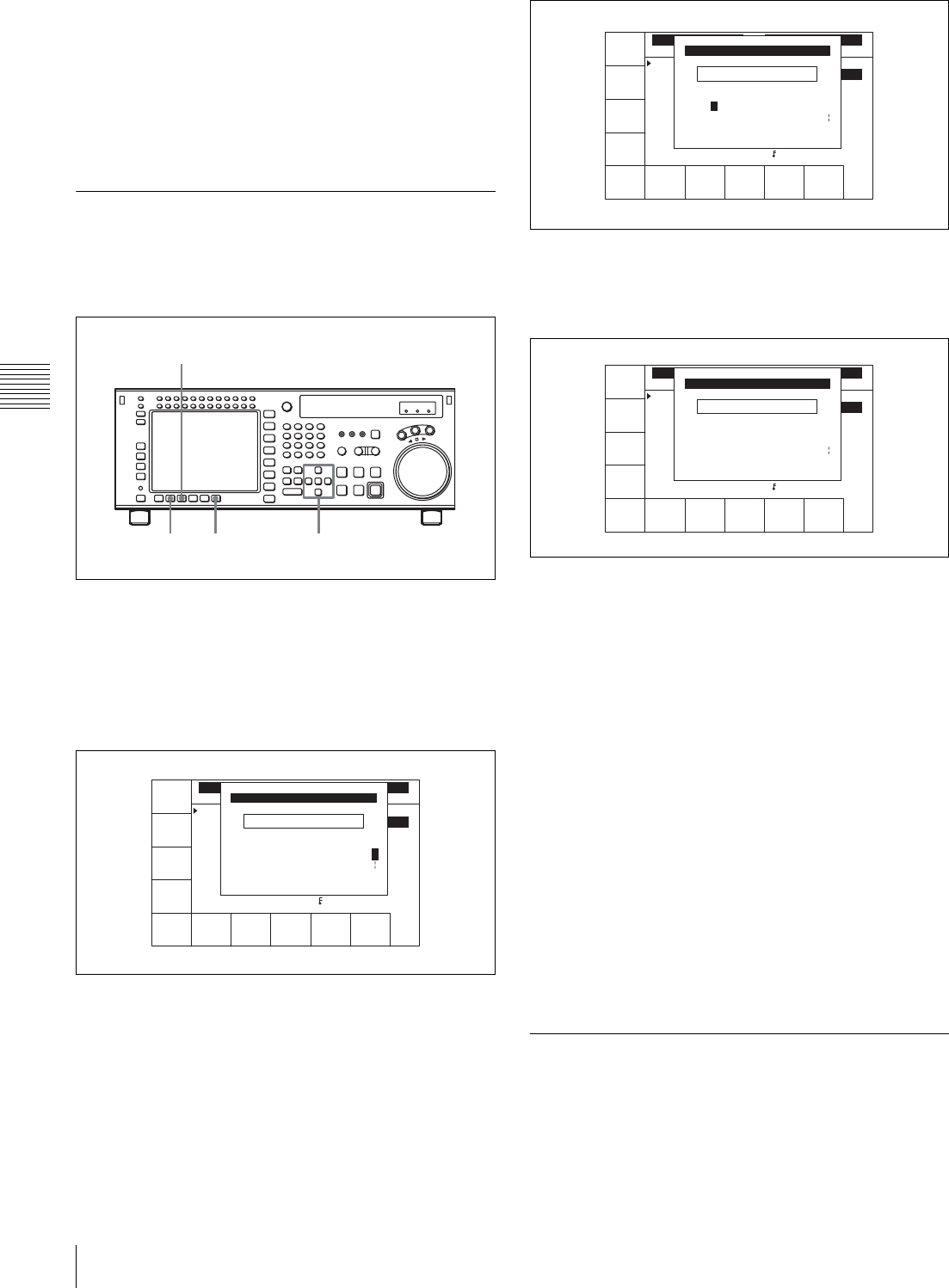
46 4-1 Registering and Storing Menu Settings
Chapter 4 Menu Settings
The VTR recalls the cue point list in the memory stick.
After the recalling process is completed, the title of the
cue point list appears under the CURRENT CUE SET
indication
8
Press the [F10] (EXIT) button.
The SET UP menu appears again.
4-1-6 Adding Titles to the Data
When storing data to a memory bank in a memory stick or
the VTR, you can add a title to the data to make data
management easier.
1
Move the cursor (B) to the item to be titled.
2
Press the [F6] (EDIT TITLE) button to display the
CURRENT SETUP TITLE EDIT window.
The VTR enters EDIT mode is entered, and the
window opens.
3
Press the cursor T or t button to select a letter.
4
Press the [F7] (SET LETTER) button or the cursor
center button.
The selected letter is entered.
5
Repeat steps 3 and 4 to enter more characters.
To enter a space
Press the [F5] (SPACE) button.
If you enter a wrong character
Press the [F6] (BACK SPACE) button to go back, then
reenter a character.
To cancel the procedure to start over again
Press [F9] (CANCEL) button to start over again.
To change a character
Press the cursor R button to enter the title box, then
press the cursor T or t button to go to the text
insertion position.
6
Press the [F10] (SAVE/EXIT) button.
The entered title is set and the menu displayed before
you pressed the [F6] (EDIT TITLE) button appears
again.
4-1-7 Details on VTR Memory Bank
and Memory Stick Functions
Most settings of most items can be stored to a VTR
memory bank or a memory stick.
26 1,3
4
SPACE SET
LETTER
CANCEL SAVE/
EXIT
BACK
SPACE
VTR BANK
SETUP BANK 1
1 (Preset)
2 (Preset)
3 (Preset)
4 (Preset)
5 (Preset)
6 (Preset)
7 (Preset)
8 (Untitled)
F (Preset)
VTR BANK
CURRENT SETUP
(Preset)
_
ABCDEFGHIJKLMNOPQRSTUVWXYZ
abcdefghjiklmnopqrstuvwxyz
0123456789[]()<>@+-*=!?:;
CURRENT SETUP TITLE EDIT
$#%&,."\^_'/~ {} HD1D2CAM
'
SPACE SET
LETTER
CANCEL SAVE/
EXIT
BACK
SPACE
VTR BANK
SETUP BANK 1
1 (Preset)
2 (Preset)
3 (Preset)
4 (Preset)
5 (Preset)
6 (Preset)
7 (Preset)
8 (Untitled)
F (Preset)
VTR BANK
CURRENT SETUP
(Preset)
f_
ABCDEFGHIJKLMNOPQRSTUVWXYZ
abcdefghjiklmnopqrstuvwxyz
0123456789[]()<>@+-*=!?:;
CURRENT SETUP TITLE EDIT
$#%&,."\^_'/~ {} HD1D2CAM
'
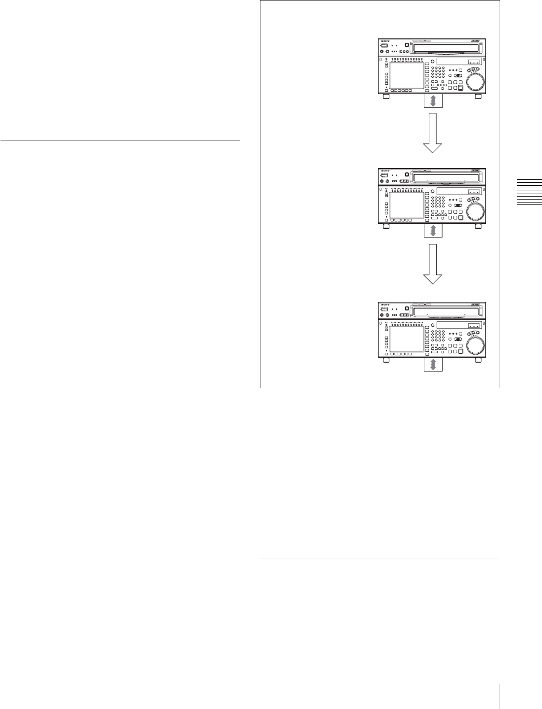
47
4-1 Registering and Storing Menu Settings
Chapter 4 Menu Settings
Data that can be stored to/recalled from a VTR
memory bank or a memory stick
•VTR SETUP data
• PF assignment data
• BANK titles
DEFAULT values for VTR SETUP can be saved and
recalled. However, DEFAULT values do not include PF
assignment data and BANK titles.
For details of saving and recalling DEFAULT values, see
“4-1-10 Saving and Recalling DEFAULT Settings on a
Bank” on page 48.
4-1-8 Memory Stick Data
Compatibility
Data copied onto a memory stick can be used on control
panels connected to other SRW-5000/5500 VTRs.
Although data is completely compatible between VTRs
with different optional equipment, take note of the
following.
Consider data copied from VTR A to VTR B and
then to VTR C
• Even though the optional equipment is different in VTRs
A and B, the VTR SETUP menu settings are preserved.
• Even though the VTR SETUP menu settings are copied
to VTR C after being copied to VTR B, the settings from
VTR A are copied to VTR C.
• Even though settings are copied for optional equipment
that is not present, the settings are adjusted and
processed by the VTR internally.
• There is complete data compatibility between the SRW-
5000 and SRW-5500. However, items which are not
available on one model or the other do not appear in the
VTR SETUP menu.
4-1-9 Automatic Reading from a
VTR Bank at Power On
By having the normally used settings saved in a bank, and
recalled automatically when the system is powered on, you
can always start operation from powering on with the same
settings.
SRW-5000
HD DIGITAL VIDEO CASSETTE RECORDER
SRW-5000
HD DIGITAL VIDEO CASSETTE RECORDER
SRW-5000
HD DIGITAL VIDEO CASSETTE RECORDER
VTR A
(HKSR-5001 FORMAT CONVERTER installed)
VTR SETUP menu
A08: FC REFERENCE select:
extern HD
Internal VTR processing:
extern HD
VTR B
(HKSR-5001 NOT installed)
VTR SETUP menu
A08: FC REFERENCE
select: extern HD
Internal VTR processing: off
VTR C
(HKSR-5001 installed)
VTR SETUP menu
A08: FC REFERENCE
select: extern HD
Internal VTR processing:
extern HD
Memory stick
Copy
Copy

48 4-1 Registering and Storing Menu Settings
Chapter 4 Menu Settings
1
Make the VTR SETUP menu and PF assignment
settings.
2
In the VTR BANK menu screen, save the current
settings in any VTR bank.
It is preferable to add a title to identify the settings, and
protect the settings not to be overwritten.
3
Press the ALT button.
This switches to the ALT + BANK menu screen.
4
Press the [F4] (POW-ON RECALL) button.
A red “P” appears to the left of the VTR BANK title.
Each time you press the [F4] (POW-ON RECALL)
button cycles the VTR bank from SETUP BANK 1 in
sequence to the FACTORY PRESET item, and then to
blank.
5
Press the ALT button, to return to the VTR BANK
menu screen.
Next time you power on, the settings will
automatically be recalled from SETUP BANK in the
VTR bank with “P” set.
Unless VTR SETUP menu item 116 “ALARM BEEP”
is set to “off” to distinguish the automatic recall from
a normal startup, a beep sound occurs twice.
4-1-10 Saving and Recalling
DEFAULT Settings on a Bank
For each VTR SETUP menu item, you can change the
factory DEFAULT value to a desired value.
For details, see “To change the DEFAULT values in a
menu item” on page 100.
These changed DEFAULT values can be saved in a VTR
BANK of the VTR.
1
Press the SET UP button.
The SETUP menu screen appears.
2
Press the ALT button.
The ALT + SETUP menu screen appears.
3
Press the [F1] (DEFAULT VTR BANK) button.
The DEFAULT VTR BANK screen appears.
The procedure for saving from CURRENT
DEFAULT to DEFAULT BANK, saving from
DEFAULT BANK or FACTORY PRESET (factory
setting) to CURRENT DEFAULT, changing the title,
or setting protection, is the same as operation on a
VTR bank.
For details, see “4-1-4 VTR Memory Bank Function”
on page 39.
Notes
• The storage region for DEFAULT BANK is one set
only.
• The title name shown in the current area is always
that for the CURRENT SETUP data. When
DEFAULT BANK data with the title changed is
written to CURRENT DEFAULT, the title of the
current area does not change.
Also, when CURRENT DEFAULT settings are
saved in DEFAULT BANK, the title of DEFAULT
BANK is copied from the title of CURRENT
SETUP.
4-1-11 Saving and Recalling
DEFAULT Settings in a “Memory
Stick”
For each VTR SETUP menu item, you can change the
factory DEFAULT value to a desired value.
For details, see “To change the DEFAULT values in a
menu item” on page 100.
The set DEFAULT values can be saved in a “Memory
Stick”.
1
Insert a “Memory Stick”.
2
Press the SET UP button.
The SET UP menu screen appears.
3
Press the ALT button.
The ALT + SETUP menu screen appears.
Note
UNDO
DIREC-
TION
B
COPY EXITEDIT
TITLE
VTR BANK
(Preset) C
VTR BANK
1 (Untitled)
F (Preset)
DEFAULT BANK 1 CURRENT DEFAULT
B

49
4-1 Registering and Storing Menu Settings
Chapter 4 Menu Settings
4
Press the [F2] (DEFAULT MEMORY CARD) button.
The DEFAULT MEMORY CARD screen appears.
The procedure for saving from CARD DEFAULT to
DEFAULT BANK or CURRENT DEFAULT, saving
from DEFAULT BANK, CURRENT DEFAULT or
FACTORY PRESET to CARD DEFAULT, changing
the title, or setting protection, is the same as operation
on a VTR bank.
For details, see “4-1-5 Memory Stick Operations” on
page 41.
Notes
• The storage region for CARD DEFAULT is one set
only.
• The title shown in the current area is always that for
the CURRENT SETUP data. When CARD
DEFAULT data with the title changed is written to
CURRENT DEFAULT, the title of the current area
does not change. Also, when CURRENT
DEFAULT settings are saved in DEFAULT BANK,
the title of DEFAULT BANK is copied from the title
of CURRENT SETUP.
• There is complete data compatibility between the
SRW-5000 and SRW-5500.
On how to check the items for which DEFAULT values
have been changed from FACTORY PRESET values,
see “To check the items for which DEFAULT values
have been changed” on page 100.
UNDO
DIREC-
TION
B
COPY EXITEDIT
TITLE
MEMORY CARD
(Untitled)
VTR BANK
C (Preset)
CARD DEFAULT DEFAULT BANK 1
B
1 (Untitled)
F (Preset)
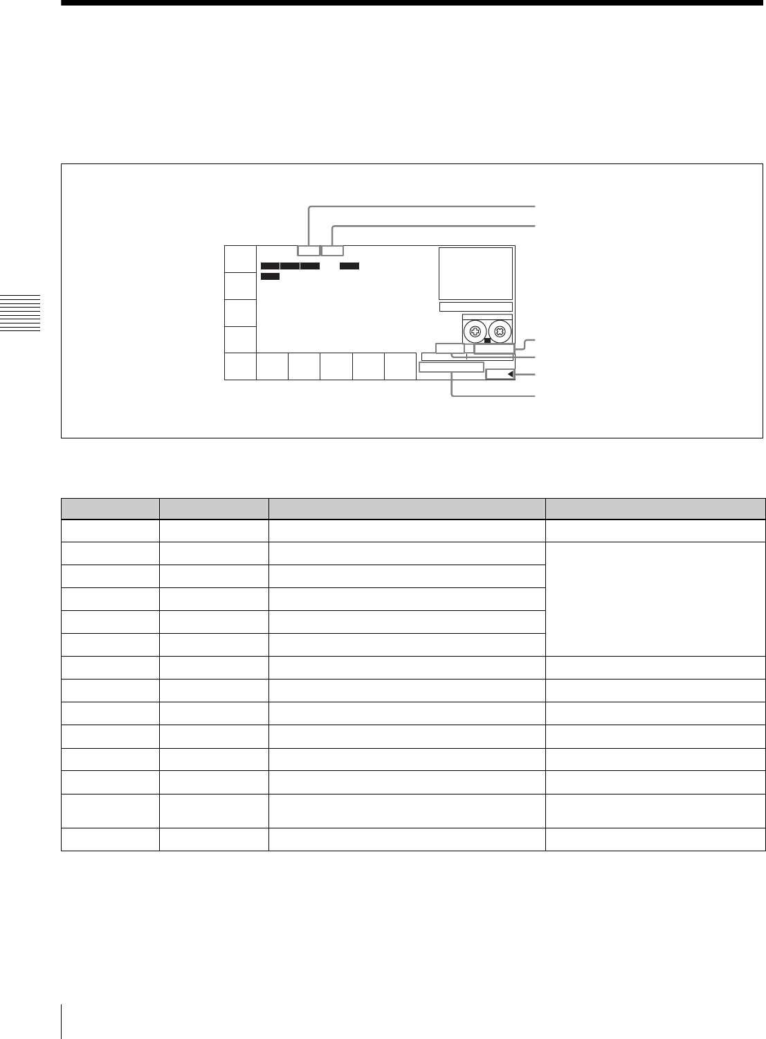
50 4-2 HOME Menu
Chapter 4 Menu Settings
4-2 HOME Menu
The HOME menu sets the basic VTR operation conditions
for recording, playback, and editing.
The HOME, VIDEO, AUDIO, TC, PF1 and PF2 menus
show information that includes the VTR operation mode,
time code of the current position, and time code type, etc.
To activate the HOME menu
Press the HOME button.
To change the HOME menu page
Press the ALT button.
For details on time codes, see “4-3 TC Menu” on page 56.
PB/EE
EE
LTC
TCR
INTRP DF F2
PLAY LOCK
RECINH
off
ASSEN-
BLE
off
INS
TC
off
INS
VIDEO
off
INS
CUE
INS
AUDIO
-
STILL HDCAM-SR
SS
REMAIN:01H06M
HOME
00
H
02
M
39
S
18
F
AIN --:--:--:-- AOUT --:--:--:--
IN --:--:--:-- OUT --:--:--:--
Operation mode
Servo lock status
Tape format
Tape running speed
Name of the displayed menu
Remaining tape amount
Button Indication Function Settings
[F1] PB/EE Selects of output signals PB, EE
[F2] REC INH Disables recording on, off
[F3] ASSEMBLE Selects edit mode and edit channel
[F4] INS TC Selects TC insert editing mode
[F5] INS VIDEO Selects VIDEO insert editing mode
[F6] INS AUDIO Opens the INS AUDIO menu
[F7] INS CUE Selects CUE insert editing mode on/off (SRW-5500 only)
ALT/[F1] PRE READ Makes a setting for pre-reading off, video, audio, a/v
ALT/[F3] FREEZE Selects still-picture output
ALT/[F6] PREROLL Sets the preroll time 0 to 30 s
ALT/[F7] DMC DMC mode on, off
ALT/[F8] STOP CODE Sets the stop code
ALT/[F9] PB EE SEL Selects the output signal in various operation
modes
ALT/[F10] LAST EDIT Restores the last edit point set
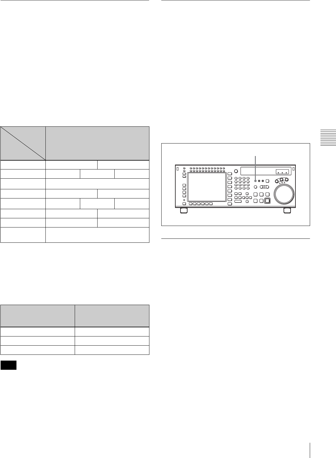
51
4-2 HOME Menu
Chapter 4 Menu Settings
4-2-1 Selecting the Output Signals
(PB/EE)
The audio/video output signals from the line output and
monitor output connectors can be temporarily changed
from their current settings to another set of settings by
pressing the [F1] (PB/EE) button. The video, digital audio,
and analog cue channel output signals are toggled to the
other set of settings while the button is pressed.
Output signal selection
Select the output signal with ALT/[F9] (PB EE SEL) or
VTR SETUP menu item 017 “PB/EE SELECT MENU”.
Output signal types for different operation modes of this
VTR are shown below.
a) Output signals during playback are PB/PB only. Output signals cannot be
selected with the VTR SETUP menu item 017 “PB/EE SELECT MENU”.
b) When the INPUT CHECK button is held down, the INPUT signals (audio
and video) are output. Output signals cannot be selected with the VTR
SETUP menu item 017 “PB/EE SELECT MENU”. When the INPUT
signals are output, only monitor output is changed. Line output signals are
not changed.
c) Pressing the [F1] (PB/EE) button changes the output signals during shuttle
mode in the following ways.
When PB/PB is selected in shuttle mode during HDCAM
playback, audio output is muted for playback speeds other
than –1 to +2 times normal speed.
4-2-2 Record Inhibit Mode (REC
INH)
Record inhibit mode is selected by pressing the [F2] (REC
INH) button. Every time the button is pressed, the setting
toggles between “off” and “on”.
The record inhibit area is selected using the VTR SETUP
menu item 003 “REC INHIBIT AREA select”.
all: All recording is prohibited. (The REC INHIBIT
indicator lights.)
crash REC: The normal record mode is disabled. Use this
setting when you want to record only during assemble
editing or insert editing.
video/CTL: Video and CTL signal recording is inhibited.
audio/CTL: Audio and CTL signal recording is inhibited.
[casst]: This is displayed when recording is inhibited
because the record-protect plug is set. This setting
cannot be selected.
4-2-3 Selecting the Edit Mode and
Edit Channel (ASSEMBLE, INS TC,
INS VIDEO, INS AUDIO and INS CUE)
Select assemble or insert edit mode.
Selecting assemble edit mode
Press the [F3] (ASSEMBLE) button in the HOME menu.
Selecting the insert edit mode
Press one of the following INSERT buttons in the HOME
menu: [F4] (INS TC), [F5] (INS VIDEO), [F6] (INS
AUDIO), [F7] (INS CUE (SRW-5500 only)).
For more information about editing operations, see
“Chapter 6 Editing” on page 115.
VTR
Operation
Mode
Video/Audio
Standby off EE/EE PB/MUTE
Standby on PB/MUTE EE/EE EE/MUTE
Playback PB/PBa)
Record EE/EE PB/PB
Shuttle c) PB/MUTE EE/EE PB/PB
Jog PB/PB PB/MUTE
Variable PB/PB PB/MUTE
INPUT CHECK
button INPUTb)
VTR SETUP menu item 017
“PB/EE SELECT MENU”
settings
Output signals while the
[F1] (PB/EE) button is held
down
PB/MUTE EE/EE
PB/PB EE/EE
EE/EE PB/MUTE
Note
Output
Channel
REC INHIBIT indicator
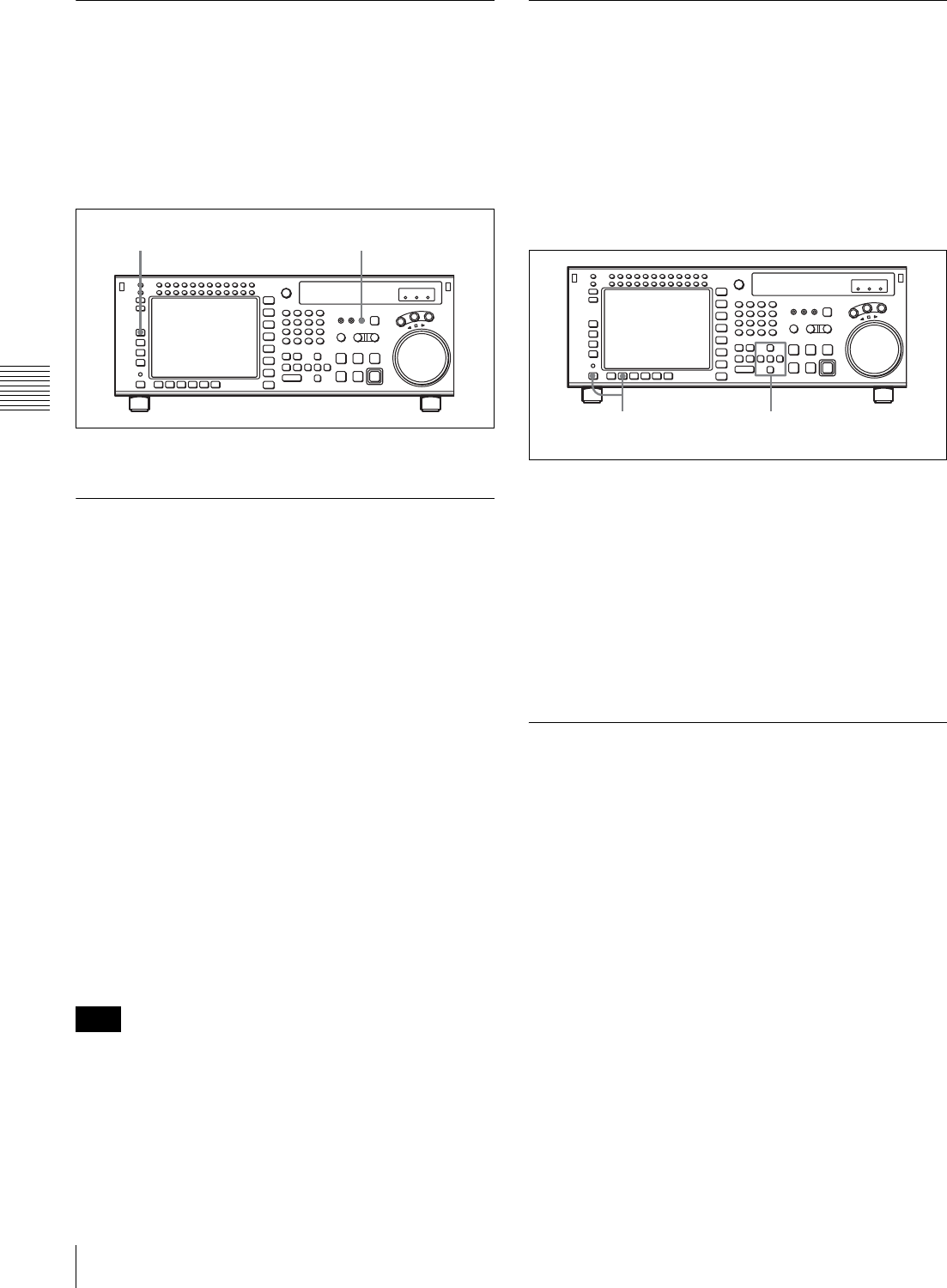
52 4-2 HOME Menu
Chapter 4 Menu Settings
4-2-4 Preread Settings (PRE READ)
This setting allows pre-reading (reading before writing) in
insert edit mode. To select pre-reading, press the ALT/[F1]
(PRE READ) buttons.
Pressing the buttons cycles the settings through on/off.
on: Preread. (Preread either video signal or audio signal. In
this case follow the EDIT PRESET setting.)
off: No pre-reading
The pre-read function can be used for pre-read editing.
4-2-5 Still-Picture Output (FREEZE)
For still-picture output, press the ALT/[F3] (FREEZE)
buttons. The picture that was playing just before the button
was pressed will be frozen on the screen. Make the field or
frame selection using the VTR SETUP menu item 902
“FREEZE MODE”.
To maintain the still-picture
Set the VTR SETUP menu item 903 “FREEZE
CONTROL FROM KEY PANEL” to “latch”.
The still-picture output is maintained until the button is
pressed again.
To temporarily output a still-picture
Set the VTR SETUP menu item 903 “FREEZE
CONTROL FROM KEY PANEL” to “momentary”. A
still-picture is output as long as you hold down the button.
Stop-freeze function
To automatically output a still-picture when the VTR is
changed to stop mode, set the VTR SETUP menu item 905
“STOP FREEZE CONTROL” to “enable”.
Regardless of the setting of the VTR SETUP menu item
902 “FREEZE MODE”, stop-freeze is a frame-freeze
picture during playback of a PsF recorded tape, and a field-
freeze picture in other modes.
4-2-6 Setting the Preroll Time
(PREROLL TIME)
Set the preroll time by pressing the ALT/[F6] (PREROLL)
buttons.
You can set a preroll time of 0 to 30 seconds in 1-second
units. During editing on this VTR, a preroll time of 5
seconds or more is recommended.
Setting the preroll time
1
Press the ALT/[F6] (PREROLL) buttons.
A data entry window appears.
2
Change the setting with the cursor R or r button.
You may also use the MULTI CONTROL knob.
3
Press the ALT/[F6] (PREROLL) buttons.
The data entry window disappears.
4-2-7 Selecting DMC Playback
(DMC)
In DMC (Dynamic Motion Control) playback mode, the
VTR plays back a tape segment at a specified variable
speed of –1 to +2 times normal playback speed,
memorizes the speed, then plays the segment back at a
later time at the memorized speed.
DMC playback is useful during on-the-spot telecasts of
sporting events for immediate playback and broadcast of
highlight scenes for which starting and ending points have
been set during recording.
For detail on the procedure for DMC playback, see “5-4-
4 DMC Playback” on page 111.
During tape editing using two SRW-5000/5500 VTRs, you
can use DMC playback to control the playback speed of
the player VTR for editing at variable speeds (DMC
editing).
Note
[F1] button PREREAD indicator
1,3 2
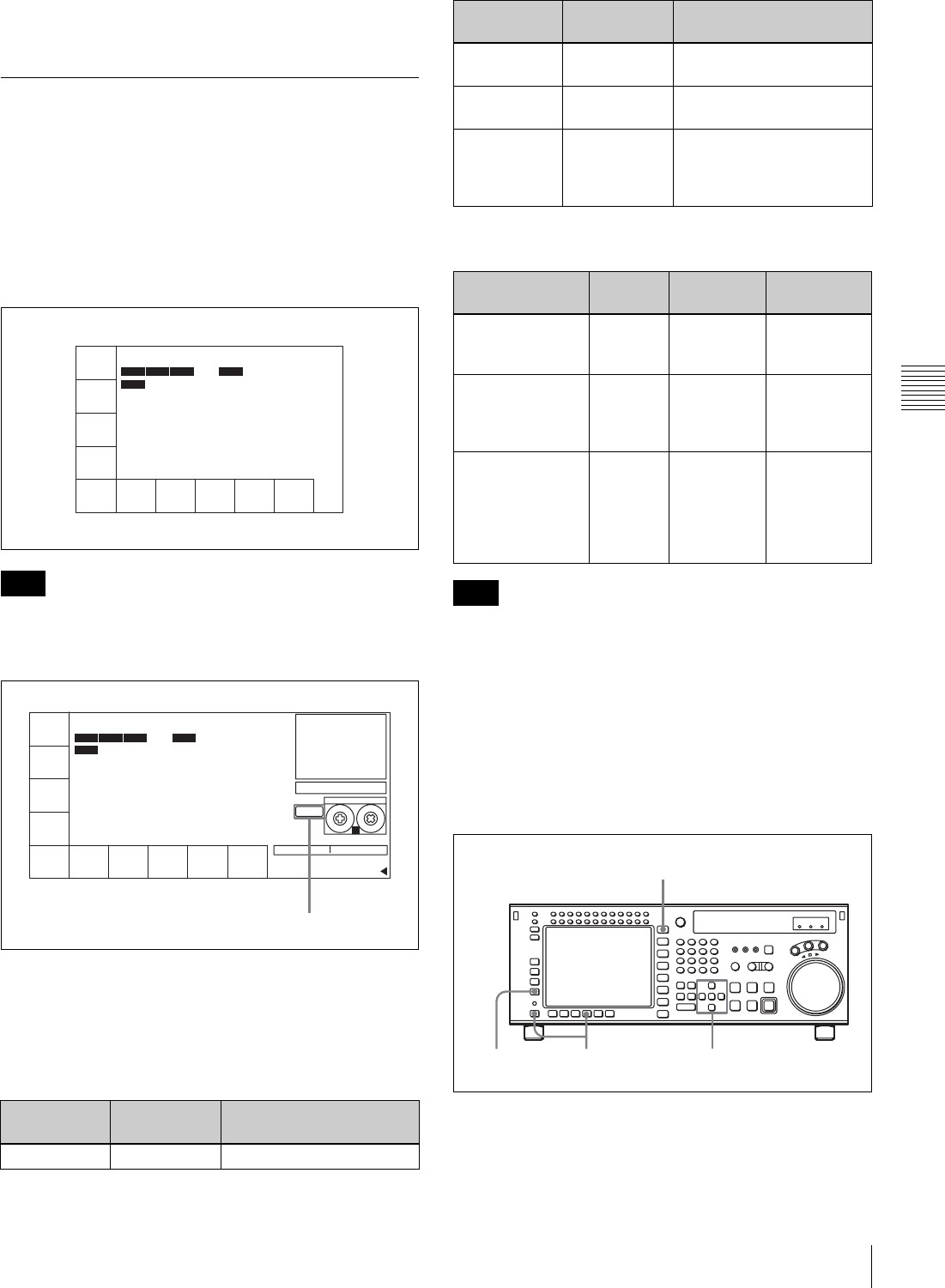
53
4-2 HOME Menu
Chapter 4 Menu Settings
For detail on the procedure for DMC editing, see “6-2-1
DMC Editing” on page 126.
4-2-8 Setting the Stop Code (STOP
CODE)
You can select the stop code detection mode (recording/
confirmation/deletion), and adjust the stop position when a
stop code is detected.
To call up the STOP CODE menu screen
Press the ALT/[F8] (STOP CODE) buttons in the HOME
menu.
If DETECT STOP is set to “ON”, “D-STOP” appears at
the side of the cassette indication, as shown in the
following figure.
s
To detect stop codes: [F2], [F3]
When playing a tape on which stop codes are recorded,
you can select four different operation modes, according to
the settings of the [F2] (DETECT BEEP) button and [F3]
(DETECT STOP) button, as follows.
The tape transport modes and speed ranges in which stop
codes can be detected are as follows.
In VAR mode, stop codes cannot be detected at ±0.03
times normal speed.
Adjusting the stop position when a stop
code is detected: [F4]
When a stop code is detected, you can adjust the position
at which the tape transport stops in the direction from the
normal stop position toward the SOM point, within the
range of 0 to 150 frames, in frame units.
1
Press the HOME button.
The HOME menu screen appears.
Note
[F2] (DETECT
BEEP) button
[F3] (DETECT
STOP) button
VTR operation when stop
code is detected
OFF OFF No operation
LTC
TCR
INTRP DF F2
TAPE LOCK
DETECT
BEEP
off
DETECT
STOP
off
DETECT
ADJUST
off
REC
ADJUST
off
CODE
REC
off
CODE
ERASE
off
EXIT
00H02M39S18F
UB 00 00 00 00
LTC
TCR
INTRP DF F2
TAPE LOCK
DETECT
BEEP
off
DETECT
STOP
off
DETECT
ADJUST
off
REC
ADJUST
off
CODE
REC
off
CODE
ERASE
off
EXIT
00H02M39S18F
UB 00 00 00 00
STILL
SET 01 30 00 00
D-STOP
SS
HDCAM-SR
REMAIN:01H06M
! TC
D-STOP
OFF ON Stops (for NORMAL PLAY
only)
ON OFF A beeper sounds for 1
second
ON ON Stops (for NORMAL PLAY
only) and simultaneously a
beeper sounds for 1
second
Transport mode
and speed
Detected Beeper
timing
Stop timing
NORMAL PLAY Yes When read
three times
Set by [F4]
(DETECT
ADJUST)
VAR, SHUTTLE
(0 to less than ±8
times normal
speed)
Yes When read
twice
No operation
REC, EDIT, JOG,
CUE UP,
PREROLL,
SHUTTLE (±8
times normal
speed or more)
No No
operation
No operation
Note
[F2] (DETECT
BEEP) button
[F3] (DETECT
STOP) button
VTR operation when stop
code is detected
23,5 4
1
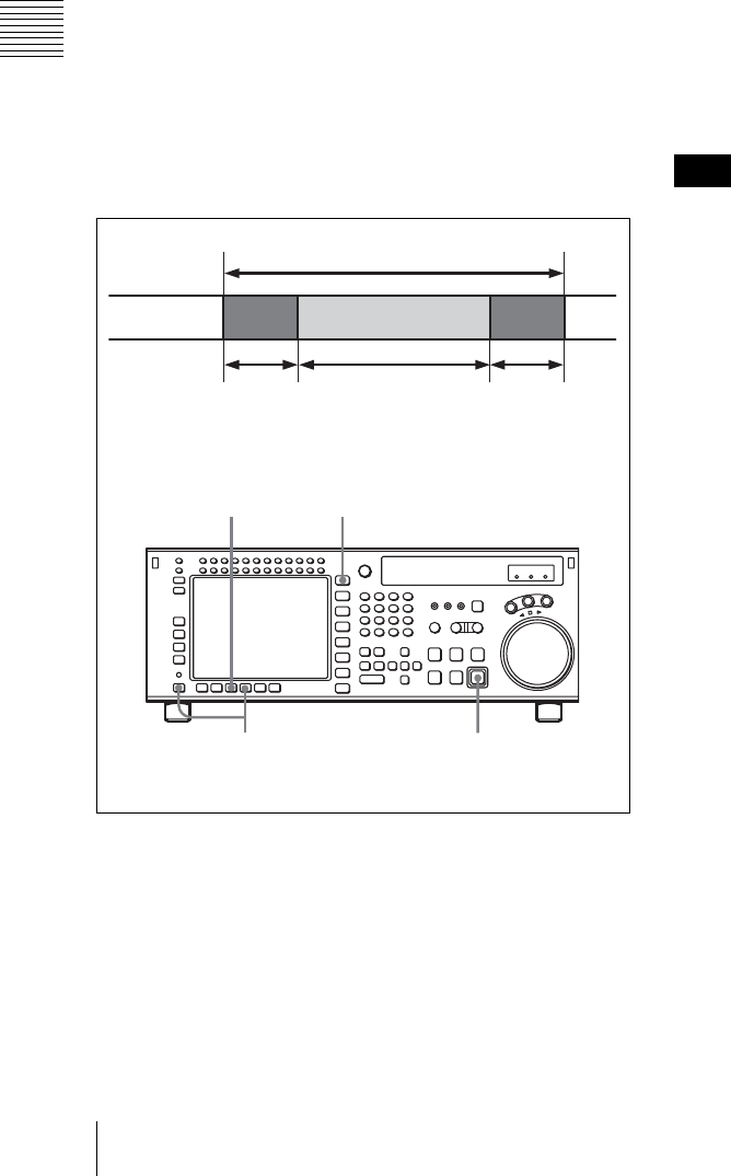
54 4-2 HOME Menu
Chapter 4 Menu Settings
2
Press the ALT/[F8] (STOP CODE) button.
The STOP CODE menu screen appears.
3
Press the [F4] (DETECT ADJUST) button.
The setting display lights up.
4
Change the setting with the cursor R or r button.
You may also use the MULTI CONTROL knob.
5
Press the [F4] (DETECT ADJUST) button.
The data entry window disappears.
Recording stop codes: [F7]
To record stop codes, press the [F7] (CODE REC) button.
In PLAY, JOG, or similar mode, cue up to the SOM point,
and press the REC/EDIT button. With the point at which
the REC/EDIT button is pressed as the SOM point, after a
preroll, the recording operation starts, and as shown in the
figure below, user bits (value 0) and stop code are
recorded, after which the unit automatically stops. After
recording is completed, the setting of the [F7] (CODE
REC) button is automatically changed to OFF.
1
Press the HOME button.
The HOME menu screen appears.
2
Press the ALT/[F8] (STOP CODE) buttons.
The STOP CODE menu screen appears.
3
Press the [F7] (CODE REC) button to select “on”.
Pressing the button toggles betwen “on” and “off”.
4
Press the REC/EDIT button.
To abandon the operation at any point
Press the STOP button.
To specify the recording start position
Press the [F5] (REC ADJUST) button, to specify how
many seconds before the SOM point the recording of the
stop code should start.
To check the recording
Press the PREVIEW/REVIEW button. The tape prerolls to
the SOM point and playback starts. If the stop code is
correctly recorded, regardless of the settings of the [F2]
(DETECT BEEP) button and [F3] (DETECT STOP)
button, a confirmation sound is emitted for 1 second, and
the unit stops in accordance with the setting of the [F4]
(DETECT ADJUST) button. If the unit does not stop even
after passing the point at which the stop code is recorded,
repeat the recording operation.
Checking the recording with the PREVIEW/REVIEW
button is only valid in the stop code menu screen.
Deleting stop codes: [F8]
To delete a stop code, press the [F8] (CODE ERASE)
button. In stop code detection mode, stop the VTR at the
stop code you want to delete, and press the REC/EDIT
button. After prerolling 5 seconds before the stop code
recording point, the VTR begins the delete operation, and
as shown in the figure below, user bits (value 0) are
recorded, after which the unit automatically stops. After
deletion is completed, the setting of the [F8] (CODE
ERASE) button is automatically changed to OFF.
UB “0” UB “0” STOP CODE
2 4
13
Section to insert time code
Tape
3 frames 20 frames 3 frames
Note
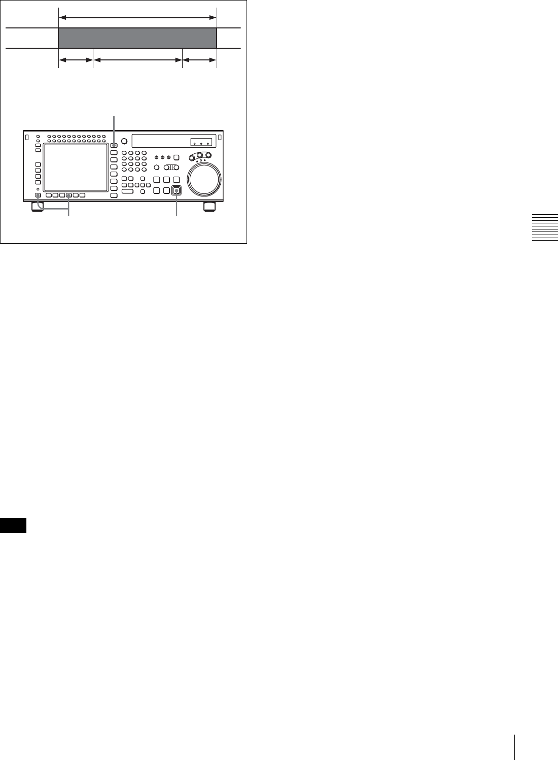
55
4-2 HOME Menu
Chapter 4 Menu Settings
1
Press the HOME button.
The HOME menu screen appears.
2
Press the ALT/[F8] (STOP CODE) buttons.
The stop code menu screen appears.
3
Press the [F8] (CODE ERASE) button to select “on”.
Pressing the button toggles betwen “on” and “off”.
4
Press the REC/EDIT button.
To abandon the operation at any point
Press the STOP button.
To check the deletion
Press the PREVIEW/REVIEW button. The VTR prerolls
5 seconds before the recording point, and starts playback.
If the unit stops at the point at which the stop code was
recorded, repeat the deletion operation.
Checking the deletion with the PREVIEW/REVIEW
button is only valid in the stop code menu screen.
Note
UB “0”
2,3 4
1
Section to insert time code
Tape
3 frames 20 frames (STOP
CODE before deletion)
3 frames
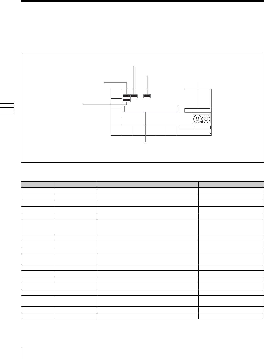
56 4-3 TC Menu
Chapter 4 Menu Settings
4-3 TC Menu
The TC menu allows you to set time code-related items
through a single menu. The HOME, TC, VIDEO, AUDIO,
PF1 and PF2 menus show information that includes the
VTR operation mode, time code of the current position,
and the time code type, etc.
To activate the TC menu
Press the TC button.
To change the TC menu page
Press the ALT button.
For details on operation modes, see “4-2 HOME Menu”
on page 50.
TIMER
SEL
UBIT LTC
TCR
INTRP DF F2
PLAY LOCK
TIMER
RESET
TIMER
SET
TIMER
HOLD
TCR
SEL
LTC
TCG
MODE
ragan
RUN
MODE
free
DF/NDF
DF
TC2
SEL
OFF
REGENE
SOURCE
int-L
STILL
TC
SET 00 00 00 07
00
H
00
M
00
S
00
F
AIN --:--:--:-- AOUT --:--:--:--
IN --:--:--:-- OUT --:--:--:--
F2
SS
HDCAM-SR
REMAIN:01H06M
INTRP (interpolation): This appears when time code cannot
be read correctly and correction has been performed.
VITC: Time code type (LTC/VITC)
F1: Field number (F1/F2)
Data entry window
TCR: Time data type
(CTL/TCR/UBR/TCG/UBG/DUR)
AIN: Time data for an AUDIO IN point
AOUT: Time data for an AUDIO OUT point
IN: Time data for an IN point
OUT: Time data for an OUT point
Button Indication Function Settings
[F1] TIMER SEL Selects time data type. CTL, TC, UBIT
[F2] TIMER RESET Resets the time counter.
[F3] TIMER SET Sets the time data.
[F4] TIMER HOLD Holds the time counter.
[F5] TCR SEL Sets the time code reader. VITC, auto, LTC
[F6] REGENE SOURCE Selects the internal or external time code generator
for TCG regeneration.
int-Lint-V
ext-L
SDI-VSDI-L
[F7] TCG MODE Sets the time code generator. regene, prst, auto
[F8] RUN MODE Selects the running mode of the time code. free, rec
[F9] DF/NDF Selects drop frame mode. DF, NDF, auto
[F10] TC2 SEL Selects the content of the second line of the time
code display.
OFF, LTC, auto, VITC, CTL, UBR
UBV, TCG, UBG
ALT/[F1] TAPE TIMER Selects the CTL display mode. + –12H, 24H
ALT/[F2] PDPSET MENU Pulldown time code preset
ALT/[F3] TC CONV MENU Frame conversion time code preset
ALT/[F4] PDTC DISP Pulldown time code display on, off
ALT/[F5] FC CHARA Superimposition of text data on FC output on, off
ALT/[F6] CHARA SUPER Specifies superimposition of character information to
the HD SDI output and HD-SD converter output.
on, off
ALT/[F7] CHARA H-POS Changes the superimposition position (horizontal). 0 to 15
ALT/[F8] CHARA V-POS Changes the superimposition position (vertical). 0 to 15
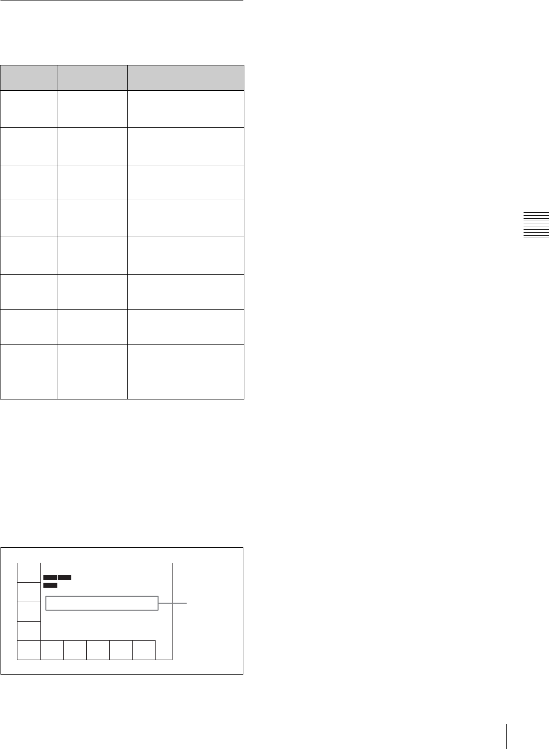
57
4-3 TC Menu
Chapter 4 Menu Settings
4-3-1 Setting the Time Data (TIMER
SEL/RESET/SET/HOLD)
The display shows the following types of time data:
1) LTC and VITC
LTC cannot be read when the tape speed is very slow or is changed
suddenly. VITC, on the other hand, can be read more accurately than LTC
when the VTR is stopped or the tape speed is very low. VITC, however,
cannot be read when the tape speed is very fast.
2) CTL signals
CTL (control) signals are pulse signals that are recorded horizontally in
each frame.
3) User bits
These represent supplementary information as part of the recorded time
code, and consist of eight hexadecimal digits (0-9 and A-F).
Time data for IN, OUT, AIN and AOUT points are also
displayed.
Selecting the time data display
Press the [F1] (TIMER SEL) button repeatedly to select the
desired time data display.
CTL: Counts the CTL signals on the playback tape or the
CTL signals being recorded on the tape, and displays
the tape running time in hours, minutes, seconds, and
frames.
TC: Displays the value read by the time code reader or the
value generated by the time code generator. To switch
between VITC and LTC, press the [F5] (TCR SEL)
button.
UBIT: Displays user bits data inserted in time code being
played back, or the user bits data inserted in time code
being recorded. To switch between VITC and LTC,
press the [F5] (TCR SEL) button.
Indication Superimposed
display
Time data type
TCR LTC TCR The LTC1) value read by
the time code reader during
playback.
TCR VITC TCR The VITC1) value read by
the time code reader during
playback.
TCG TCG The value generated by the
time code generator during
recording.
CTL CTL The number of CTL
signals2) on the tape during
recording/playing.
UBR LTC UBR The user bits3) value read
by the time code reader
(LTC) during playback.
UBR VITC UBR The user bits value read by
the time code reader (VITC)
during playback.
UBG UBG The user bits value
generated by the time code
generator during recording.
DUR DUR Appears whenever a
duration between any two
edit points (IN, OUT, AUDIO
IN or AUDIO OUT points) is
displayed.
TIMER
SEL
TC
TIMER
RESET
TIMER
SET
TIMER
HOLD
TCR
SEL
VITC
TCG
MODE
ragan
RUN
MODE
free
DF/NDF
DF
TC2
SEL
PEGENE
SOURCE
00
H
00
M
00
S
00
F
AIN --:--:--:-- AOUT --:--:--:--
IN --:--:--:-- OUT --:--:--:--
LTC
TCR
INTRP
PLAY LOCK
Time data for
edit points
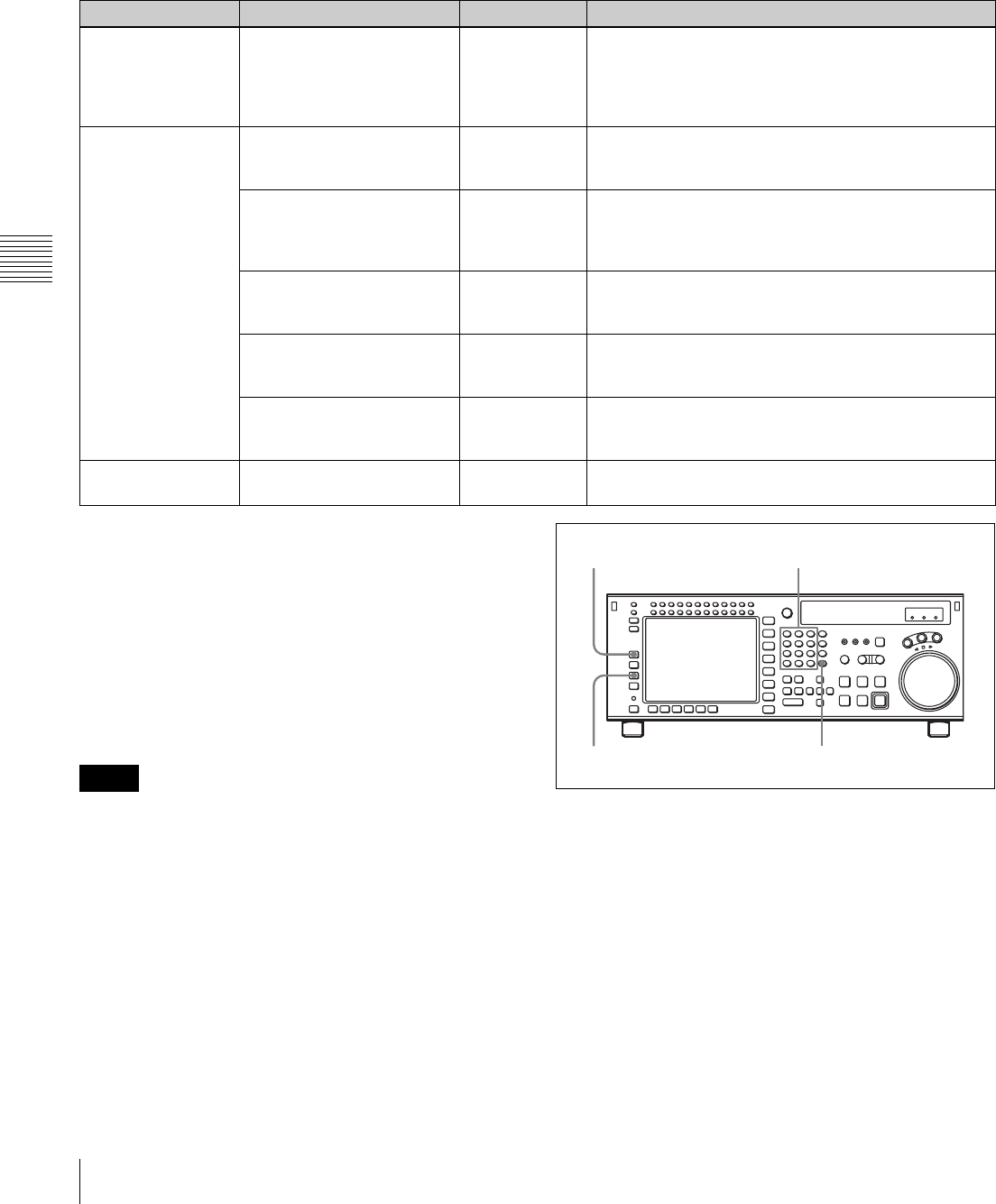
58 4-3 TC Menu
Chapter 4 Menu Settings
Selecting the time code and the user bits to be recorded
Use the [F6], [F7], and [F9] buttons in the TC menu to
specify the time code and the user bits to be recorded. The
specifications for the various button settings are shown in
the following table.
1) The DF/NDF setting on the [F9] button is applied to the time code only
when “prst” is specified by the [F7] button; the DF/NDF setting is always
applied for the CTL timer.
2) Specify the signal to be regenerated with the VTR SETUP menu item 608
“TCG/UBG REGENE MODE”. Signals not specified by this menu item
are automatically set to Preset mode, regardless of the [F7] button setting.
Setting time codes
To set time codes, select “prst” with the [F7] (TCG
MODE) button in the TC menu and then follow the steps
below.
• Set the [F8] (RUN MODE) button to “rec” before setting
the time data for recording. When you select “rec”, time
data advances from a set value only during recording.
When you select “free”, time code advances in real time
after the initial value has been set.
• During recording, VITC is always written to the AUX
data area of the video signal.
1
Press the [F1] (TIMER SEL) button to select the TC
(time code) to be set.
2
Enter the new setting in the data entry window with the
numeric buttons.
For example, to enter 01H00M30S00F, press 1, 0, 0, 3,
0, 0, 0. (The leading 0 is not required. When the
entered value is less than eight digits, the leading
digit(s) is (are) set to 0 when you press the SET
button.)
[F7] (TCG MODE) [F6] (REGENE SOURCE) [F9] (DF/NDF) Time code and user bits recorded
prst DF/NDF/auto1) TC/UB enables TCG/UBG values to be recorded. Any
time code can be specified for the time code generator
and the user bits generator. The running mode for the
recorded time code data conforms to that specified by
the [F9] button.
regene2) int-L TC/UB enables TCG/UBG values to be recorded. The
time code generator and the user bits generator lock to
the time data recorded longitudinally on the tape.
int-V TC/UB enables TCG/UBG values to be recorded. The
time code generator and the user bits generator lock to
the time data recorded in the video signal AUX data
area on the tape.
ext-L TC/UB enables TCG/UBG values to be recorded. The
time code generator and the user bits generator lock to
the time data input from the TIME CODE IN connector.
SDI-V TC/UB enables TCG/UBG values to be recorded. TCG/
UBG values are controlled by VITC time data in the
video signal input to the HD SDI INPUT A/B connector.
SDI-L TC/UB enables TCG/UBG values to be recorded. TCG/
UBG values are controlled by LTC time data in the
video signal input to the HD SDI INPUT A/B connector.
auto “regene/int-L” is set in assemble or insert mode and
“prst” is set in other modes.
Notes 3
4
21
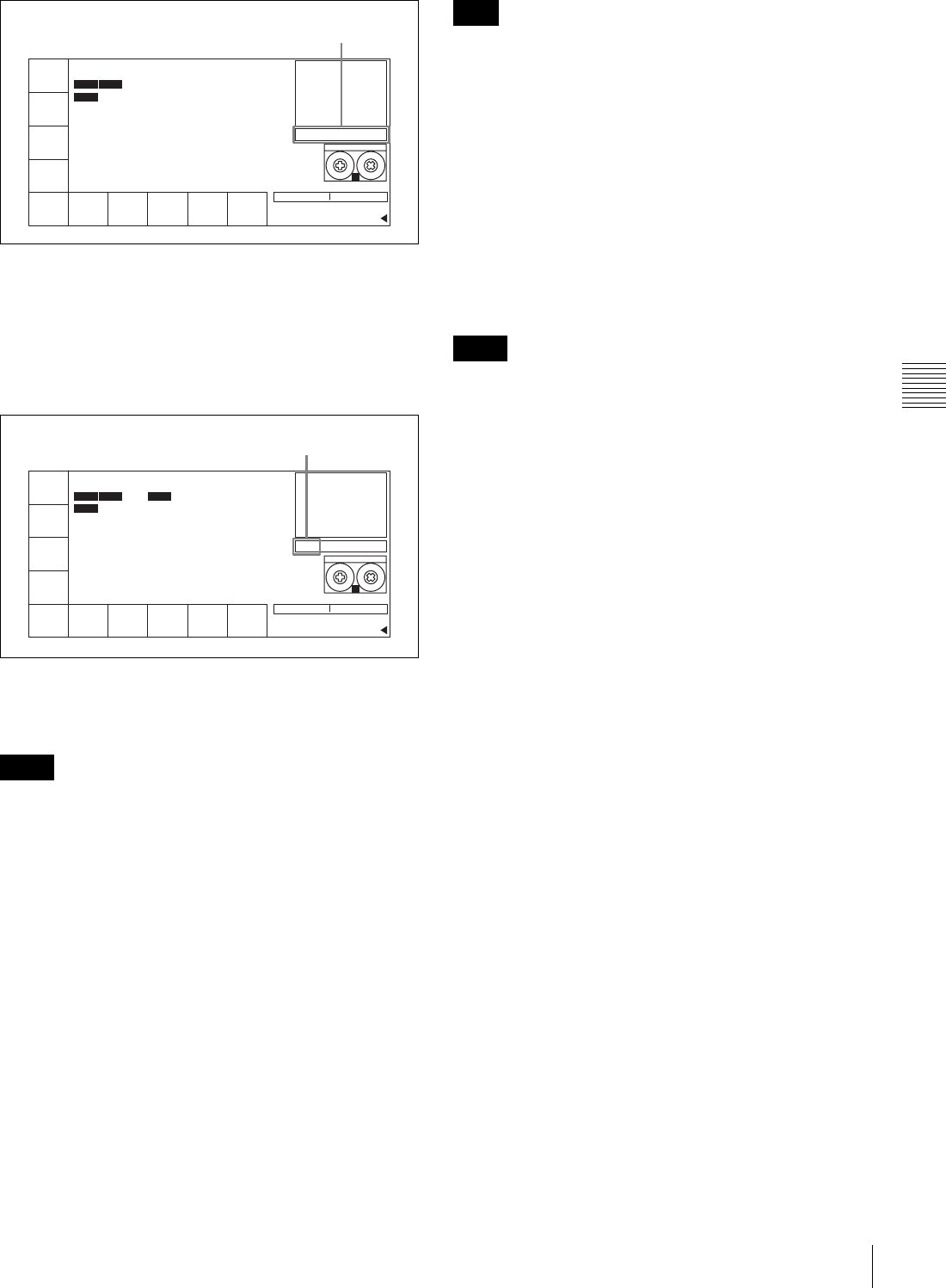
59
4-3 TC Menu
Chapter 4 Menu Settings
To cancel entered values
Press the CLR button.
3
Press the SET UP button to set the entered value.
If you pressed the + or – button, then entered a value,
the result of calculation appears in the display.
4
Press the [F3] (TIMER SET) button.
The input value is set as the time code.
• Time codes from an external time code generator cannot
be set.
• Time codes cannot be set when the internal time code
generator is locked to external time codes or to time
codes read by the time code reader.
Setting the CTL timer
1
Press the [F1] (TIMER SEL) button to select CTL.
2
Enter data in the data entry window using the number
buttons.
3
Press the SET button to set the data.
4
Press the [F3] (TIMER SET) button.
When ±12H is selected in the VTR SETUP menu item 605
“TAPE TIMER DISPLAY” and a value of 10H or more is
entered, the first digit will be dropped.
Resetting time data
Press the [F2] (TIMER RESET) button.
The internal time code generator is reset according to the
setting of the [F1] (TIMER SEL) button.
Resetting TC or UBIT data
The internal time code generator is reset and the time data
display becomes 00H00M00S00F (TC) or 00 00 00 00
(UBIT). Edit points are not affected.
• Time data read by the time code reader cannot be reset.
• Time data cannot be reset when the internal time code
generator is locked to external time codes or to time
codes read by the time code reader.
Setting the user bit value
1
Press the [F1] (TIMER SEL) button to select UBIT.
2
Enter the desired user bit value in hexadecimal
notation using the numeric buttons.
Press the 0 to 5 buttons while holding down the SFT
button to enter the letters A to F.
3
Press the [F3] (TIMER SET) button.
Recording the current time
1
Press the [F9] (DF/NDF) button to select “DF”.
2
Press the [F8] (RUN MODE) button to select “free”.
3
Enter the target time with the numeric buttons while
verifying the data in the data entry window.
4
When the target time arrives, press the [F3] (TIMER
SET) button.
The time code generator starts operating from the
specified time.
Notes
TIMER
SEL
TC INTRP DF F2
TIMER
RESET
TIMER
SET
TIMER
HOLD
TC
SEL
VITC
TCG
MODE
prst
RUN
MODE
rec
DF/NDF
DF
TC2
SEL
REGENE
SOURCE
STILL
SET 01 30 00 00
00
H
00
M
00
S
00
F
AIN --:--:--:-- AOUT --:--:--:--
IN --:--:--:-- OUT --:--:--:--
LTC
TCR
INTRP
PLAY LOCK
SS
HDCAM-SR
REMAIN:01H06M
! TC
Data entry window
DF F2
TIMER
HOLD
DF/NDF
DF
STILL
00
H
00
M
00
S
00
F
LTC
TCR
2FD
TIMER
SEL
TC
TIMER
RESET
TIMER
SET
TC
SEL
VITC
TCG
MODE
prst
RUN
MODE
rec
TC2
SEL
REGENE
SOURCE
INTRP
SET 01 30 00 00
AIN --:--:--:-- AOUT --:--:--:--
IN --:--:--:-- OUT --:--:--:--
INTRP
PLAY LOCK
SS
HDCAM-SR
REMAIN:01H06M
! TC
SET is displayed.
Note
Notes

60 4-3 TC Menu
Chapter 4 Menu Settings
To pause the current time
Press the [F4] (TIMER HOLD) button.
The time is paused only while the button is held down.
4-3-2 Setting the Time Code Reader
(TCR SEL)
Press the [F5] (TCR SEL) button to select the time code to
be read by the time code reader during playback.
VITC: Reads VITC.
auto: Reads VITC when the playback speed is ±1/2 times
normal speed or less, and LTC when it is greater than
±1/2 times normal speed.
LTC: Reads LTC.
Depending on the time code recorded on a tape, VITC or
LTC appears on the display.
Time codes that are read by the time code reader or played
back are output from the TIME CODE OUT connector.
4-3-3 Setting the Time Code
Generator (TCG SOURCE/MODE)
There are two ways to record time codes on the VTR. One
way is to record the output of the VTR’s internal time code
generator. The other is to directly record time codes that
are input from an external time code generator.
The output from the internal time code generator can either
be set to a specified initial value, or synchronized with an
external time code generator.
The internal time code generator time code settings are
made with the [F6] (REGENE SOURCE)/[F7] (TCG
MODE) buttons. Menu selections and settings are shown
in the following table.
Regenerated signals are selected using the VTR SETUP
menu item 608 “TCG/UBG REGENE MODE setting”.
To check the running of the internal time code
generator
Press the INPUT CHECK button.
4-3-4 Selecting the Time Code
Running Mode (RUN MODE)
Press the [F8] (RUN MODE) button to select the time code
running mode.
free: The time code advances when the power is on
regardless of the VTR’s operation mode.
rec: The time code advances only during recording.
Note
TCG
[F6]
(REGENE
SOURCE)
[F7] (TCG
MODE)
Setting
Internal TCG
(Preset)
prst Time codes
can be freely
set using the
internal time
code generator
Internal TCG
(Regenerate)
int-LTC regene Lock to the
time data
recorded on
the time code
tracks
int-VITC regene Lock to the
time data
recorded as
video AUX data
on the tape
ext-LTC regene Lock to the
time data on
the TIME
CODE IN
connector
SDI-V regene Lock to the
VITC time data
in the video
signal from the
HD SDI INPUT
A/B connector
SDI-L regene Lock to the LTC
time data in the
video signal
from the HD
SDI INPUT A/B
connector
auto “int-LTC/
regene” is set
in assemble or
insert mode
and “prst” is set
in other modes
Note
Menu
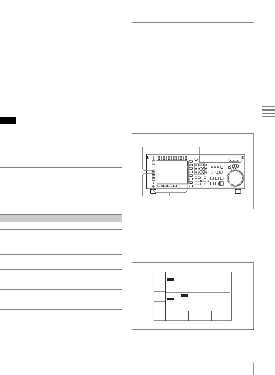
61
4-3 TC Menu
Chapter 4 Menu Settings
4-3-5 Selecting the Drop Frame
Mode (DF/NDF)
Press the [F9] (DF/NDF) button to select the running mode
for the CTL counter and the time code generator.
DF: Drop frame mode1) (DF is displayed.)
NDF: Non-drop frame mode2) (NDF is displayed.)
auto: The unit switches to drop frame mode when the field
frequency is 29.97 Hz, and switches to non-drop
frame mode when the field frequency is 30 Hz.
1) Drop frame mode
In order to compensate for differences between time code values from the
time code generator and the actual time that occurs when the frame
frequency of this unit is 29.97 Hz, the drop frame mode causes the time
code generator to omit the first two frames (frame 00 and 01) in each
minute except the tenth.
2) Non-drop frame mode
In this mode, drop frame mode processing is not performed. Since there is
no frame cutting, a discrepancy of about 86 seconds occurs each day in the
case of a frame frequency of 29.97 Hz.
• This setting is only active when the frame frequency of
the unit is 29.97 Hz or 30 Hz.
• When the [F7] (TCG MODE) button is set to “regene”,
the drop frame mode is inoperative since the time code
generator is synchronized to the playback time code.
4-3-6 Selecting the Content of the
Second Time Code Display Area
(TC2 SEL)
Select the content of the second time code display area
using the [F10] (TC2 SEL) button.
When the two-unit editing display, a warning, or similar is
shown, the second time code display area does not appear.
For details about the warnings, see “Warning Messages”
on page 135.
4-3-7 Selecting CTL Display Mode
(TAPE TIMER)
Press the ALT/[F1] (TAPE TIMER) buttons to select a 12-
hour or 24-hour clock for the CTL display.
+ –12H: 12-hour clock
24H: 24-hour clock
4-3-8 Presetting Pulldown Time
Code (PDPSET MENU)
(when HKSR-5001 is installed)
To preset the pulldown time code when this VTR is
operated in 23.98PsF/24PsF mode, use the following
procedure.
1
Press the TC button, then press the ALT button.
You can also press the ALT and TC buttons
simultaneously.
2
Press the [F2] (PDPSET MENU) button.
The PDPSET menu appears.
3
Press the [F1] (PRESET MODE) button to select 24F
or 30F time code to be preset.
Notes
Setting Time data displayed
OFF No display
LTC LTC value read from the time code reader
Auto When the playback speed is within the range ±1/2
normal speed, then VITC, and if outside this
range then the LTC is displayed.
VITC VITC value read from the time code reader
CTL CTL signal count value
UBR User bits read by the time code reader (LTC)
UBV User bit value read from the time code reader
(VITC)
TCG Value generated by the time code generator
UBG User bits value generated by the time code
generator
2
543
1
PRESET
MODE
24F
DF F2
PDTIME
SET
EXITPD TC
DF/NDF
NDF
INTRP DF 2FO
00H00M00S00F
00H00M00S00F
24F
30F
INTRP
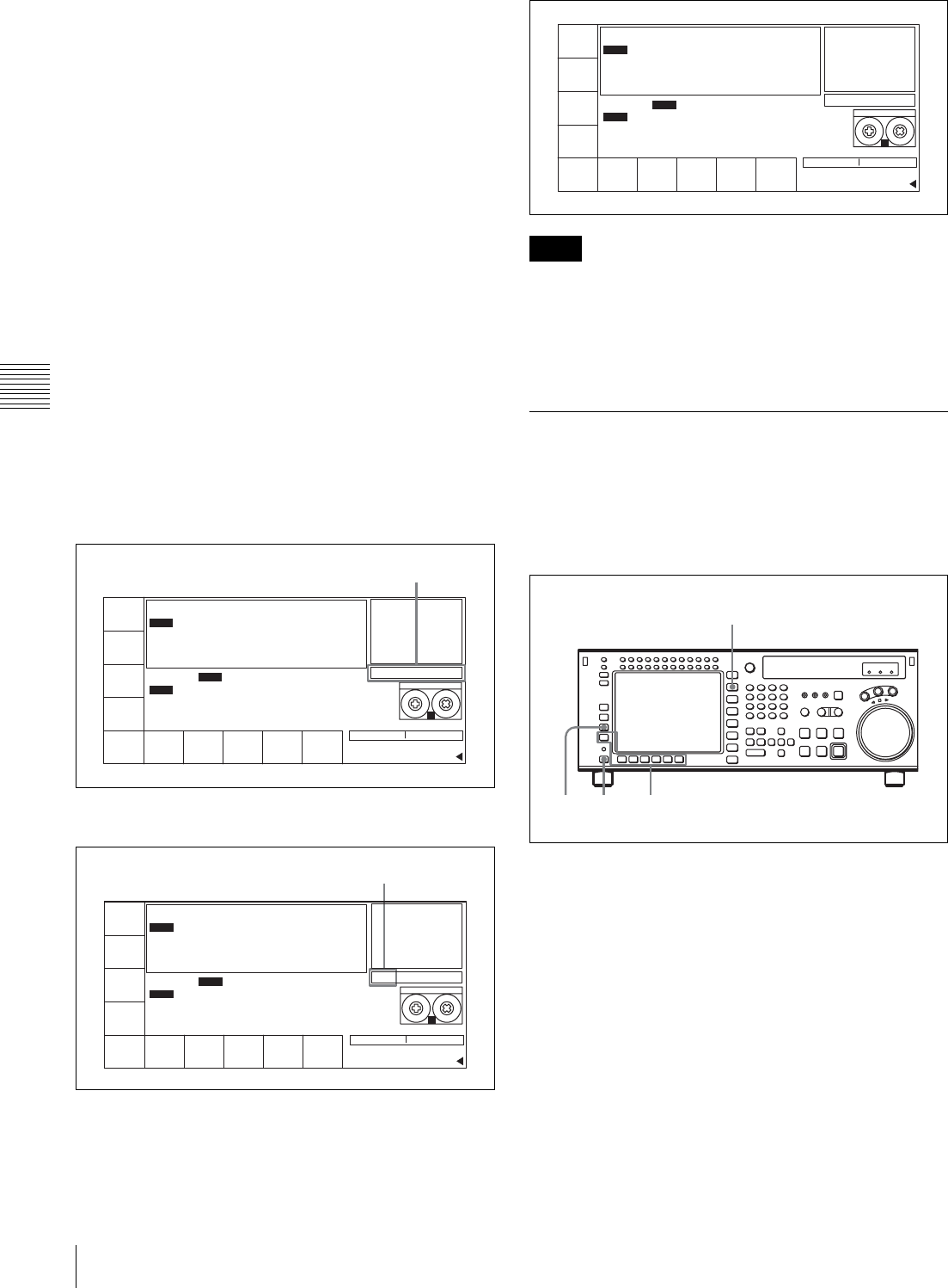
62 4-3 TC Menu
Chapter 4 Menu Settings
The selected time code is framed with the thick line.
Each press of the button switches time code between
24F and 30F.
24F: Presets the 24 frames time code. The A frame of
the pulldown sequence is preset.
30F: Presets the 30 frames time code. The A frame of
the pulldown sequence is preset.
4
• When 30F is selected in the step 3:
Press the [F6] (PDTC DF/NDF) button to select DF or
NDF.
This selection is effective only for 30F time code.
DF: Drop frame mode
NDF: Non-drop frame mode
auto: The unit switches the running mode (DF/NDF)
automatically according to the frame frequency of
the unit. When the frame frequency is 23.98 Hz,
the unit switches to the drop frame mode and
switches to the non-drop frame mode when it is
24 Hz.
• When 24F is selected in the step 3:
Skip this step.
5
Enter the time code data in the data entry window with
numeric buttons.
6
Press the SET button to set the input data.
7
Press the [F2] (PDTIME SET) button.
• Once the time code is preset, it cannot be reverted.
• Operation information display cannot be displayed while
the pulldown time code appears.
• The pulldown time code cannot be displayed while the
machine-to-machine editing display appears.
4-3-9 Presetting for Conversion
from Frame Time Code (TCCONV
MENU)
Use the following procedure to set the time code
conversion settings.
1
Press the TC button, and then press the ALT button.
The ALT+TC menu appears.
2
Press the [F3] (TCCONV MENU) button.
The TC CONVERT menu appears.
PRESET
MODE
24F
RDTIME
SET
EXITPD TC
DF/NDF
DF
STILL
01 00 30 00
SS
HDCAM-SR
REMAIN:01H06M
! ALT+TC
DF F2
INTRP DF 2FO
00
H
00
M
00
S
00
F
00
H
00
M
00
S
00
F
24F
30F
INTRP
Data entry window
PRESET
MODE
24F
RDTIME
SET
EXITPD TC
DF/NDF
DF
STILL
SET 01 00 30 00
SS
HDCAM-SR
REMAIN:01H06M
! ALT+TC
DF F2
INTRP DF 2FO
00
H
00
M
00
S
00
F
00
H
00
M
00
S
00
F
24F
30F
INTRP
SET is displayed.
Notes
PRESET
MODE
24F
RDTIME
SET
EXITPD TC
DF/NDF
DF
STILL
SS
HDCAM-SR
REMAIN:01H06M
! ALT+TC
DF F2
INTRP DF 2FO
01H00M30S00F
00H00M00S00F
24F
30F
INTRP
31
1
2
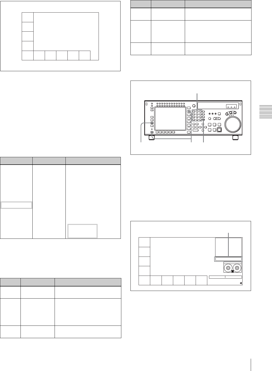
63
4-3 TC Menu
Chapter 4 Menu Settings
STARTING TC: Time code used as a reference when
converting time code.
JUMPING TC: The loopback point for converting
time code with STARTING TC as the reference
point, and the conversion done in both forward
and reverse directions.
The time code is discontinuous at this point.
The following table shows an example of how the 25 frame
time code is discontinuous when the operating frequency
is 25PsF, the playback tape is 24 frames, and STARTING
TC is 01:00:00:00, and 24F JUMPING TC 22:00:00:00
(JUMP TC SEL=–3H).
3
If necessary, use the function buttons to change the
settings.
For details on the settings made by these buttons, see
the following table.
To preset the 24F STARTING TC using the
numeric buttons
1
Press the TC button, and then press the ALT button.
The ALT+TC menu appears.
2
Press the [F3] (TCCONV MENU) button.
The TC CONVERT menu appears.
3
Enter the time code in the data entry window with the
numeric buttons.
4
Press the SET button to set the time code.
24 Frames TC 25 Frames TC
JUMPING TC 22:00:00:00 20:09:36:00
::
01:00:01:01 01:00:01:00
Forward direction 01:00:01:00 01:00:00:24
M::
STARTING TC 01:00:00:00 01:00:00:00
m00:59:59:23 00:59:59:24
Reverse direction ::
22:00:00:01 22:07:12:01 Non-
consecutive
part
JUMPING TC 22:00:00:00 21:09:36:00
Button Indication Function
[F3] TC CONV Specifies whether the time code
is converted to time code or not.
[F4] ORG TC DISP Specifies whether the time code
is displayed or not on two lines
in the HOME, TC, and PF
menus along with the converted
time code.
[F6] START TC PST Press to preset the STARTING
TC using the numeric buttons.
TC
CONV
on
ORG TC
disp
on
START
TC ENT
JUMP
TC SEL
+3H
EXITSTART
TC PST
00H00M00S00F
STARTING TC
03H00M00S00F
JUMPING TC
00H00M00S00F
CURRENT TC
[F7] START TC ENT Press to enter the current time
code as the STARTING TC.
[F8] JUMP TC SEL Selects the JUMPING TC as an
interval from STARTING TC.
Selectable values: –3H, –2H,
–1H, +1H, +2H, +3H, 0H
[F10] EXIT Select to exit the TC CONVERT
menu.
Button Indication Function
41
2
3
TCCONV
MENU
on
ORG TC
DISP
on
START
TC ENT
JUMP
TC SEL
-3H
EXITSTART
TC PST
STILL
01 00 00 00
SS
HDCAM-SR
REMAIN:01H06M
! ALT+TC
00
H
00
M
00
S
00
F
STARTING TC
03
H
00
M
00
S
00
F
JUMPING TC
00
H
00
M
00
S
00
F
CURRENT TC
Data entry window
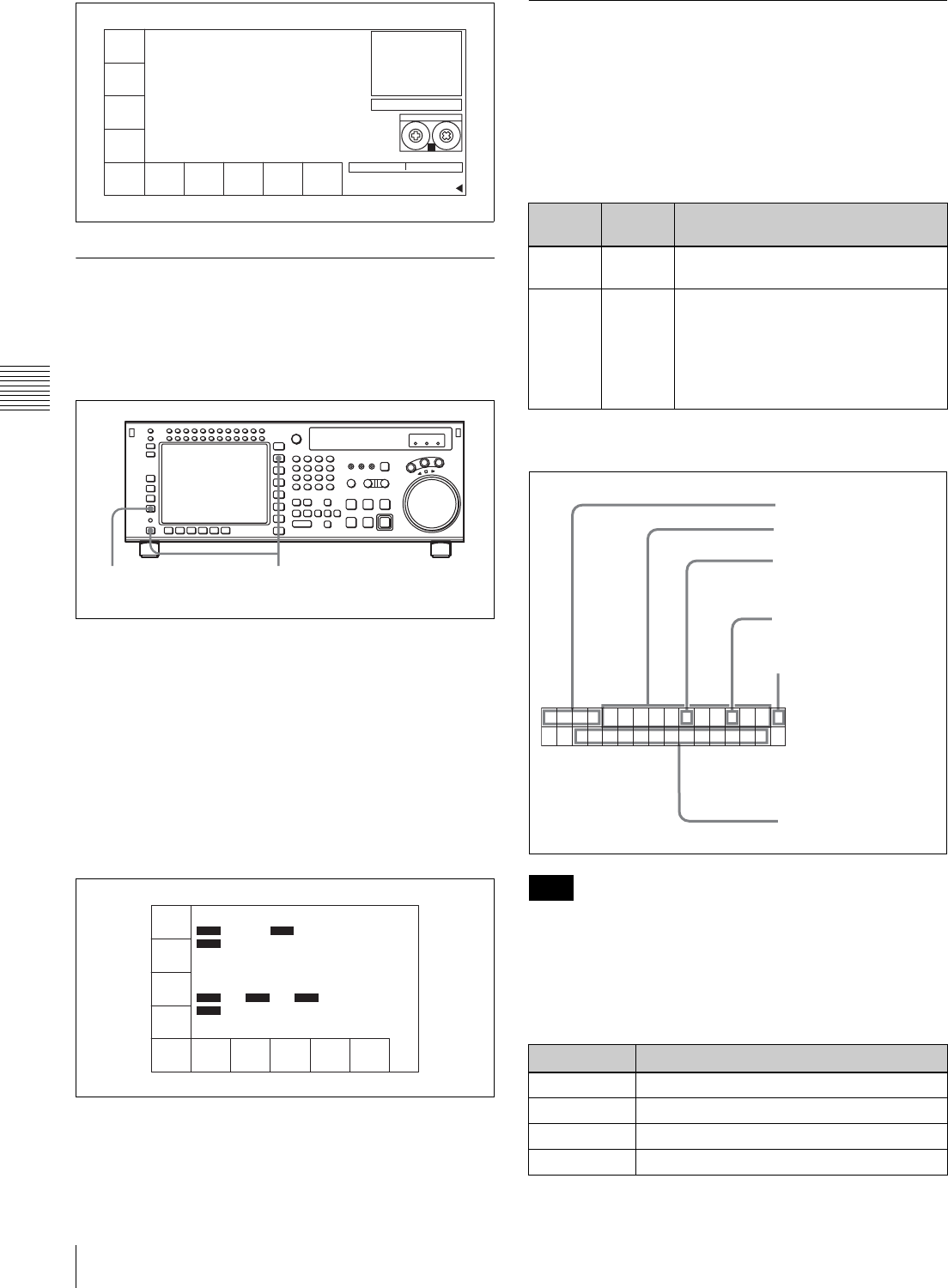
64 4-3 TC Menu
Chapter 4 Menu Settings
4-3-10 Displaying the Pulldown Time
Code (PDTC DISP) (when HKSR-
5001 is installed)
To display the pulldown time code, follow the steps below.
1
Press the TC button, then press the ALT button.
The ALT+TC menu appears.
2
Press the [F4] (PDTC DISP) button to select
(highlight) “on”.
Each time you press the button, “on” and “off”
alternate.
on: Displays the pulldown time code.
off: Does not display the pulldown time code.
4-3-11 Superimposition of Character
Information (PD CHARA/CHARA
SUPER/H-POS/V-POS)
To superimpose the characters representing time code data
and operation mode information on the output signals, use
the ALT/[F4] (PD CHARA) and ALT/[F6] (CHARA
SUPER) buttons.
Contents of superimposed data
The example above shows the factory-set contents of data.
By changing the setting of the VTR SETUP menu item 626
“DISPLAY INFORMATION select”, different types of
information can also be displayed on the second line.
aTypes of time data
TCCONV
MENU
on
ORG TC
DISP
on
START
TC ENT
JUMP
TC SEL
-3H
EXITSTART
TC PST
STILL
SET 01 00 00 00
SS
HDCAM-SR
REMAIN:01H06M
! ALT+TC
00H00M00S00F
STARTING TC
03H00M00S00F
JUMPING TC
00H00M00S00F
CURRENT TC
2 1
TAPE
TIMER
12H
PDPSET
MENU
-
TC
CONV
off
PDTC
DISP
off
PD
CHARA
off
CHARA
H-POS
10
CHARA
V-POS
10
VITC
POS-1
16
VITC
POS-2
16
CHARA
SUPER
off
00H00M00S00F
00H00M00S00F
AIN 00:01:10:00 AOUT 00:02:10:00
IN 00:01:20:00 OUT 00:02:20:00
INTRP DF F2
INTRP DF 2FO F2
LTC
TCR
2FD
LTC
TCR
PLAY LOCK
Button Setting Connector to which the characters
are superimposed
ALT/[F4] on FORMAT CONV. OUT connector (on
two connectors)
ALT/[F6] on • MONITOR connector of HD SDI
OUTPUT
• SD OUT COMPOSITE (MONITOR)
connector
• MONITOR connector of SD SDI
OUT
Note
Symbol Meaning
CTL CTL counter data
TCR LTC reader time code data
UBR LTC reader user bit data
TCR. VITC reader time code data
TCR.23:59.40.18*
SHUTT LEST I LL
1 Types of time data
Time data
2 Drop frame mark of the
time code reader
3 Drop frame mark of the
time code generator
4 Field mark of the
VITC data
5 Operation mode
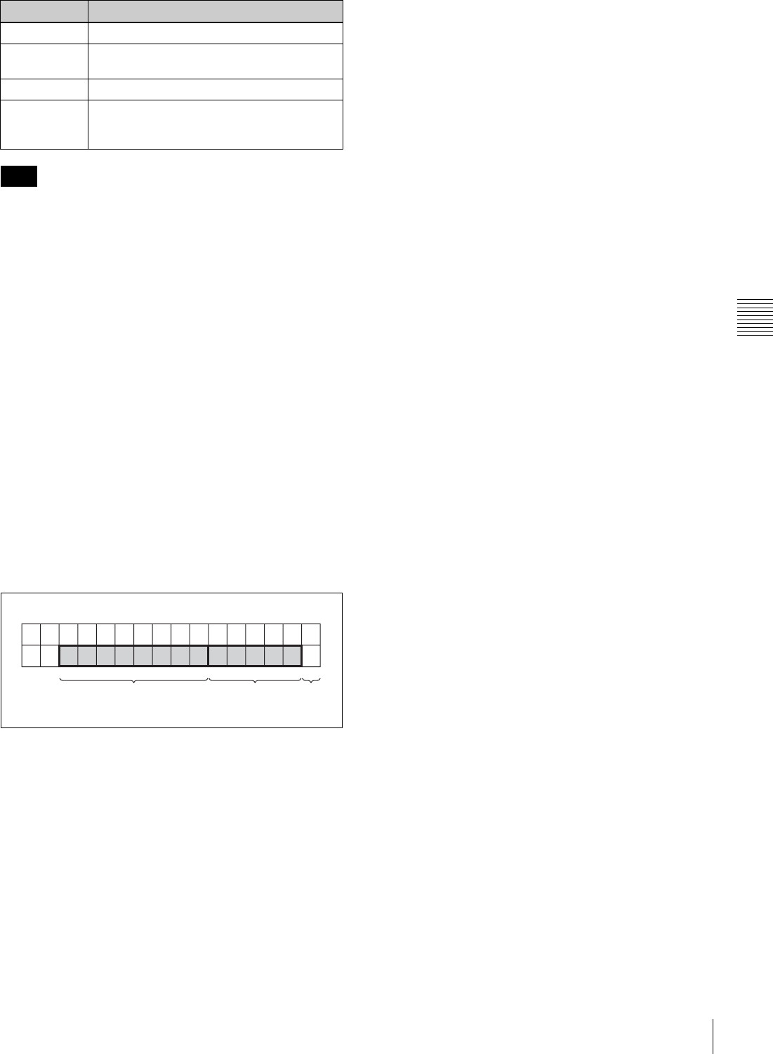
65
4-3 TC Menu
Chapter 4 Menu Settings
When time data or user bits are not read correctly, a “*”
will be displayed in this block so that the symbols become
“T*R”, “U*R”, “T*R.”, “U*R.”, etc.
bDrop frame mark of the time code reader
“ • ”: drop frame mode
“ : ”: non-drop frame mode
cDrop frame mark of the time code generator
“ • ”: drop frame mode
“ : ”: non-drop frame mode
dField mark of the VITC data
“ ”: (blank space) fields 1 and 3
“ * ”: fields 2 and 4
eOperation mode
The contents are divided into blocks A and B as shown
below.
Block A: Indicates the operation mode.
Block B: Indicates the tape speed or servo lock status.
Block C: A x mark here indicates an edit section for
automatic editing.
UBR. VITC reader user bit data
TCG Time code data from the time code
generator
UBG User bit data from the time code generator
DUR The duration between any two of the four
edit points (IN, OUT, AUDIO IN, and AUDIO
OUT)
Note
Symbol Meaning
ABC
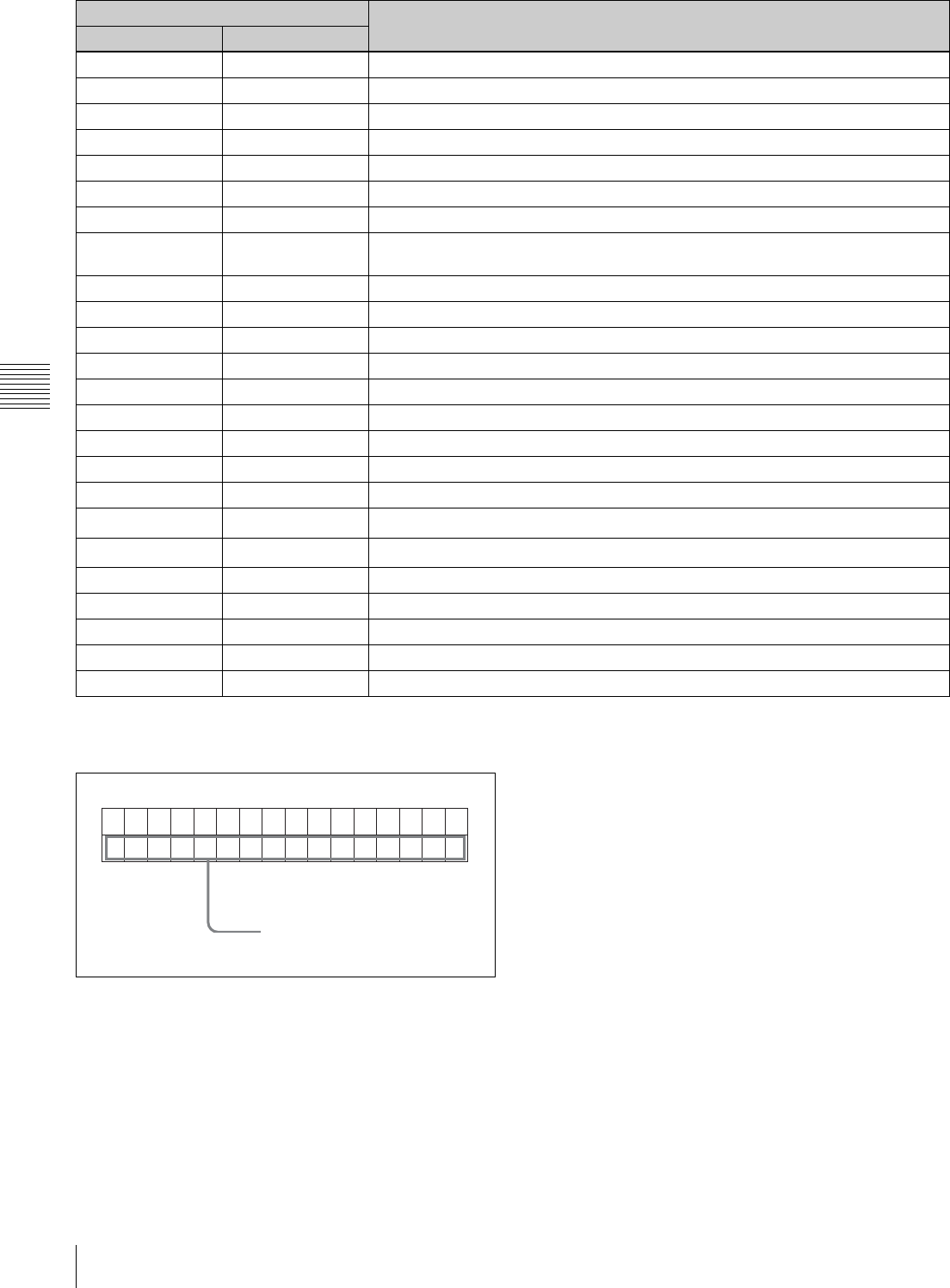
66 4-3 TC Menu
Chapter 4 Menu Settings
a) Initial speed or memorized speed
To display a warning message
Set the VTR SETUP menu item 626 “DISPLAY
INFORMATION select” to any setting other than “time
data only” and set the menu item 627 “CHAR WARNING
DISPLAY at dual line mode” to “on”. The first 16
characters of the warning message flashes on the second
line.
For details about the warning messages, see “Warning
Messages” on page 135.
When there are multiple warning messages, each message
flashes twice before it is replaced by the next message.
When there is no warning message, the setting of the VTR
SETUP menu item 626 “DISPLAY INFORMATION
select” flashes on the second line instead.
To display remaining time on the tape
Use the VTR SETUP menu item 628 “REMAIN TIME
DISPLAY” to display remaining time on the tape.
off: Do not display remaining time.
10min: Display remaining time when it is 10 minutes or
less.
on: Always display remaining time.
Display Operation mode
A block B block
TAPE UNTHREAD Cassette not inserted
STANDBY OFF Standby off mode
T.RELEASE Tension release mode
STOP Stop mode
PREROLL Preroll mode
PLAY Playback mode (servo unlocked)
PLAY LOCK Playback mode (servo locked)
PLY-SPD Speed shift from
normal speed (%)
Capstan override mode
REC Record mode (servo unlocked)
REC LOCK Record mode (servo locked)
EDIT Edit mode (servo unlocked)
EDIT LOCK Edit mode (servo locked)
JOG STILL Still-picture jog mode
JOG FWD Forward jog (B is lit)
JOG REV Reverse jog (b is lit)
SHUTTLE (speed) Shuttle mode
VAR (speed) Variable mode
DMC (speed a))DMC memorize mode
D-PREV (speed a))DMC edit preview mode
DMC EDIT DMC edit mode
DMC-SPD (speed) DMC initial speed setting
PREVIEW Preview mode
AUTO EDIT Auto edit mode
REVIEW Review mode
TCR 2 3 5 9 4 0 1 8.:::*
OXTRNLEFEEARE
N
The first 16 characters of the
warning message
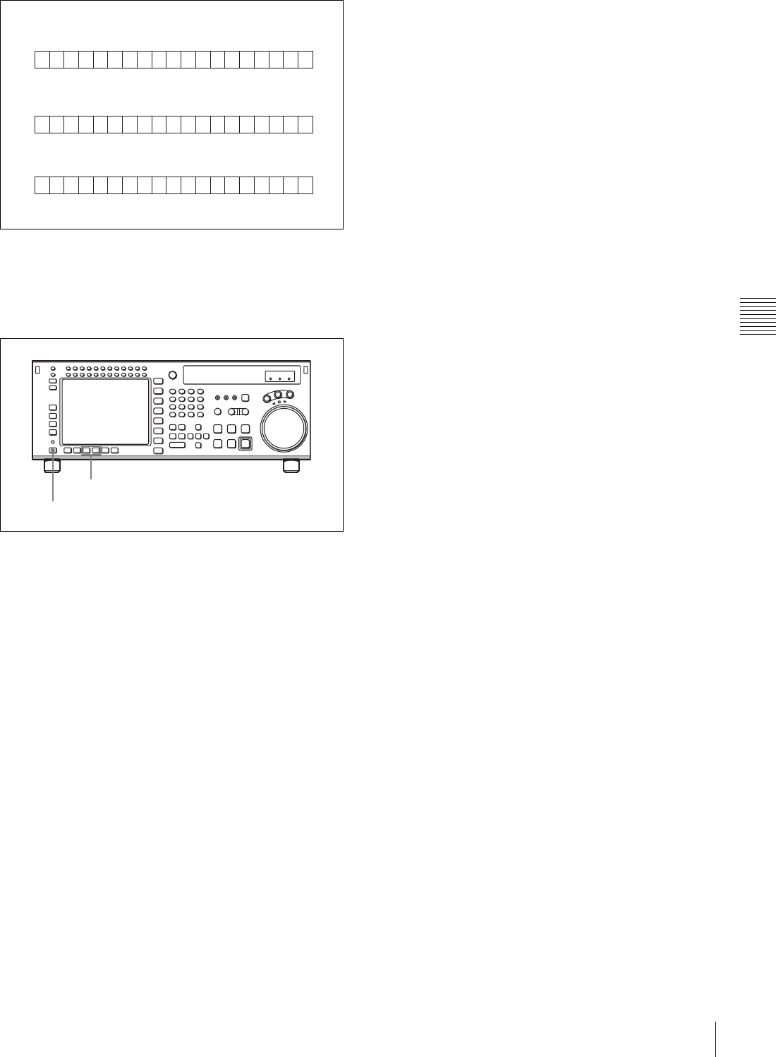
67
4-3 TC Menu
Chapter 4 Menu Settings
Changing the superimpose position
The superimpose position can be set to 16 different
positions in the horizontal directions (0 to 15) and 24
different positions in the vertical directions (0 to 23).
To move in the horizontal direction, press the ALT/
[F7](CHARA H-POS) buttons, and to move in the vertical
direction, press the ALT/[F8] (CHARA V-POS) buttons.
Each cursor button press increments the setting by 1. From
the maximum value, the next value is the minimum value.
Switching to a menu screen other than the TC menu screen
also ends the setting.
TCR23594018.:: :*
TCR23594018.:: :*
TCR23594018.:: :*
R23
R5
R--
When remaining time is 23 minutes.
When remaining time is five minutes.
When remaining time to is 100 minutes or over.
[F7], [F8] buttons
ALT button
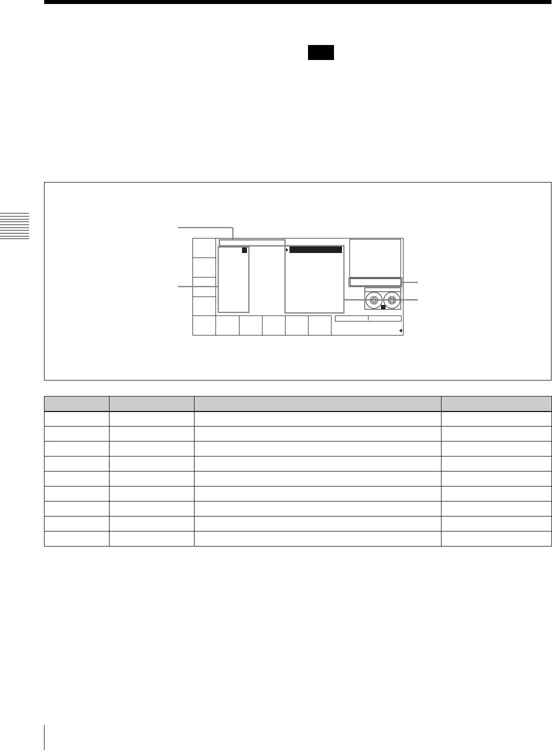
68 4-4 CUE Menu
Chapter 4 Menu Settings
4-4 CUE Menu
Cue points can be registered in a total of 10 pages
(numbered 0 to 9), to a total of 100 cue points (numbered
0 to 99). Each page can hold a maximum of 10 cue points.
Cue point settings, deletions, and page settings are done
through the CUE menu.
For details on storing cue point data, see “4-1-5 Memory
Stick Operations” on page 41.
To activate the CUE menu
Press the CUE button.
Cue point data is factory set to be erased when a cassette is
inserted.
To select whether to erase cue point data when a
cassette is inserted
Press the [F10] (M-CUE CLEAR) button to select whether
to erase cue point data when a cassette is inserted.
on: Erase cue point data.
off: Do not erase cue point data.
Note
Button Indication Function Settings
[F1] PREV PAGE Shows the previous page.
[F2] NEXT PAGE Shows the next page.
[F4] TELE FILE Opens the TELE FILE menu.
[F5] CUE P-ROLL Specifies the preroll time to a cue point. 0 to 30 s
[F8] PAGE SET Specifies the page number.
[F9] CUENUM SET Specifies the cue number.
[F10] M-CUE CLEAR Erases cue point data when a cassette is inserted. on, off
ALT/[F8] PAGE M O DE S e lec t s PAG E mo d e.
ALT/[F9] EXTEND MODE Selects EXTEND mode.
PREV
PAGE
NEXT
PAGE
TELE
FILE
-
CUE
P-ROLL
0sec
PAGE
SET
CUENUM
SET
M-CUE
CLEAR
on
STILL
77 77 77 77
[(Blank) ]
PAGE: 0
1
2
3
4
5
6
7
8
9
EOS[--:--:--:--]
0
1
2
3
4
5
6
7
8
9 SS
HDCAM-SR
REMAIN:01H06M
! CUE
Title indication
Page number indication Data entry window
Cue point indication
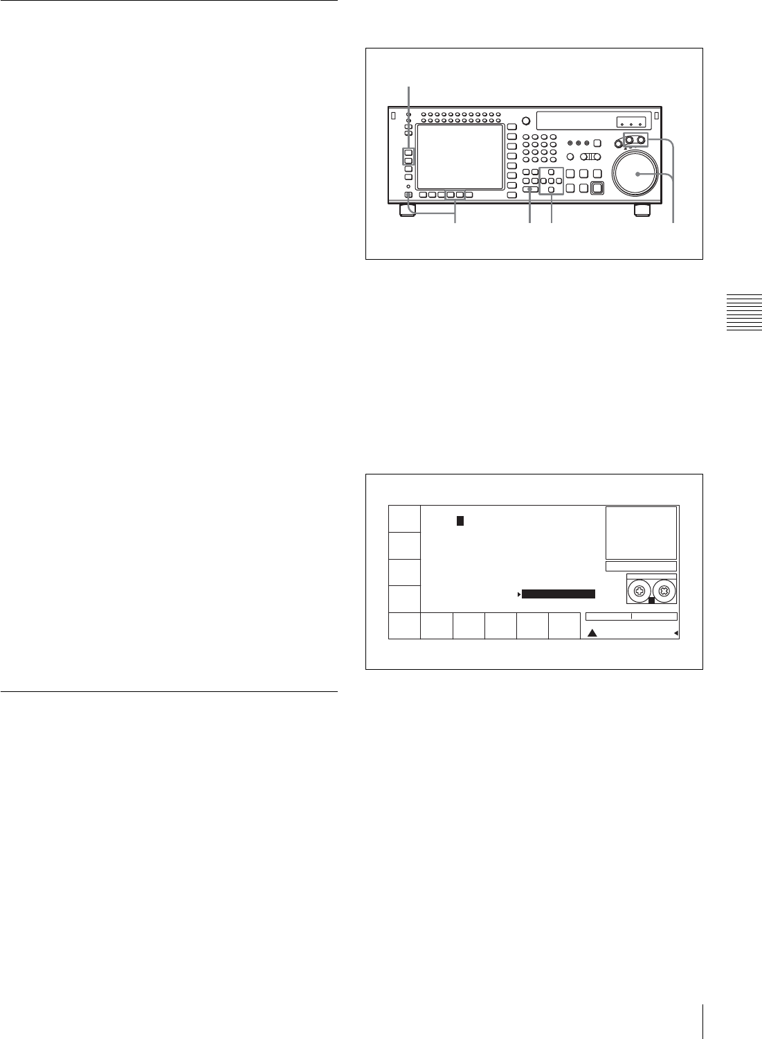
69
4-4 CUE Menu
Chapter 4 Menu Settings
4-4-1 Selecting a Multi-Cue Mode
The SRW-5000/5500 has the following two multi-cue
modes.
PAGE mode
Press the ALT/[F8] (PAGE MODE) buttons.
In PAGE mode, cue point data can be accessed by page
number, thus speeding up cue point registration and cuing
operations.
Display
Cue points are displayed in groups of 10, number 0 to 9, 10
to 19, etc. Each display is a page.
Selecting a page
There are the three following ways to select a page:
• Press the [F1] (PREV PAGE) button.
The previous page is shown.
• Press the [F2] (NEXT PAGE) button.
The next page is shown.
• Enter the desired page number with the numeric button,
then press the [F8] (PAGE SET) button.
If you enter 1, for example, page one appears, containing
cue point numbers 10 to 19.
EXTEND mode
Press the ALT/[F9] (EXTEND MODE) buttons.
In EXTEND mode, you can do operations that cannot be
done in page units, such as the consecutive registration of
more than 10 cue points.
Display
The screen displays a list of 100 consecutive cue points
which can be scrolled. Press the R or r button to scroll the
list. Page columns are not displayed.
To quickly scroll through a list
Press the R or r button while holding down the SFT button.
4-4-2 Registering Cue Points
There are two ways to register cue points: (1) by direct
registration of the tape address when the ENTRY button is
pressed, and (2) by the entry of cue point data with the
numeric buttons.
Registering cue points by pressing the
ENTRY button
1
Press the ALT/[F8] (PAGE MODE) buttons or the
ALT/[F9] (EXTEND MODE) buttons.
2
If you selected PAGE mode, press the [F1] (PREV
PAGE) button or [F2] (NEXT PAGE) button to select
a desired page (or use the numeric buttons to enter the
page number in the data entry window, then press the
[F8] (PAGE SET) button).
3
Press the R or r button to move the cursor (B) to the
cue number to be registered.
To select the cue number directly by numeric
buttons
Enter the cue number in the data entry window with
the numeric buttons, then press the [F9] (CUENUM
SET) button.
4
Press the JOG or VAR button, then rotate the MULTI
CONTROL knob to find the position where you want
to register the cue point.
5
Press the ENTRY button at the selected position.
The current tape address of the position where the
button is pressed is registered as a cue point.
Press the ENTRY button repeatedly to register the cue
point repeatedly. The cue number will automatically
increment by one each time.
1 5 43
2
PREV
PAGE
NEXT
PAGE
TELE
FILE
CUE
P-ROLL
PAGE
SET
CUENUM
SET
M-CUE
CLEAR
STILL
77 77 77 77
[(Blank) ]
PAGE: 0
1
2
3
4
5
6
7
8
9
EOS[--:--:--:--]
0 00:00:00:00
1 00:00:00:00
2 00:00:00:00
3 00:00:00:00
4 00:00:00:00
5 00:00:00:00
6 00:00:00:00
7 00:00:00:00
8 00:00:00:00
9 00:00:00:00 SS
HDCAM-SR
REMAIN:01H06M
! CUE
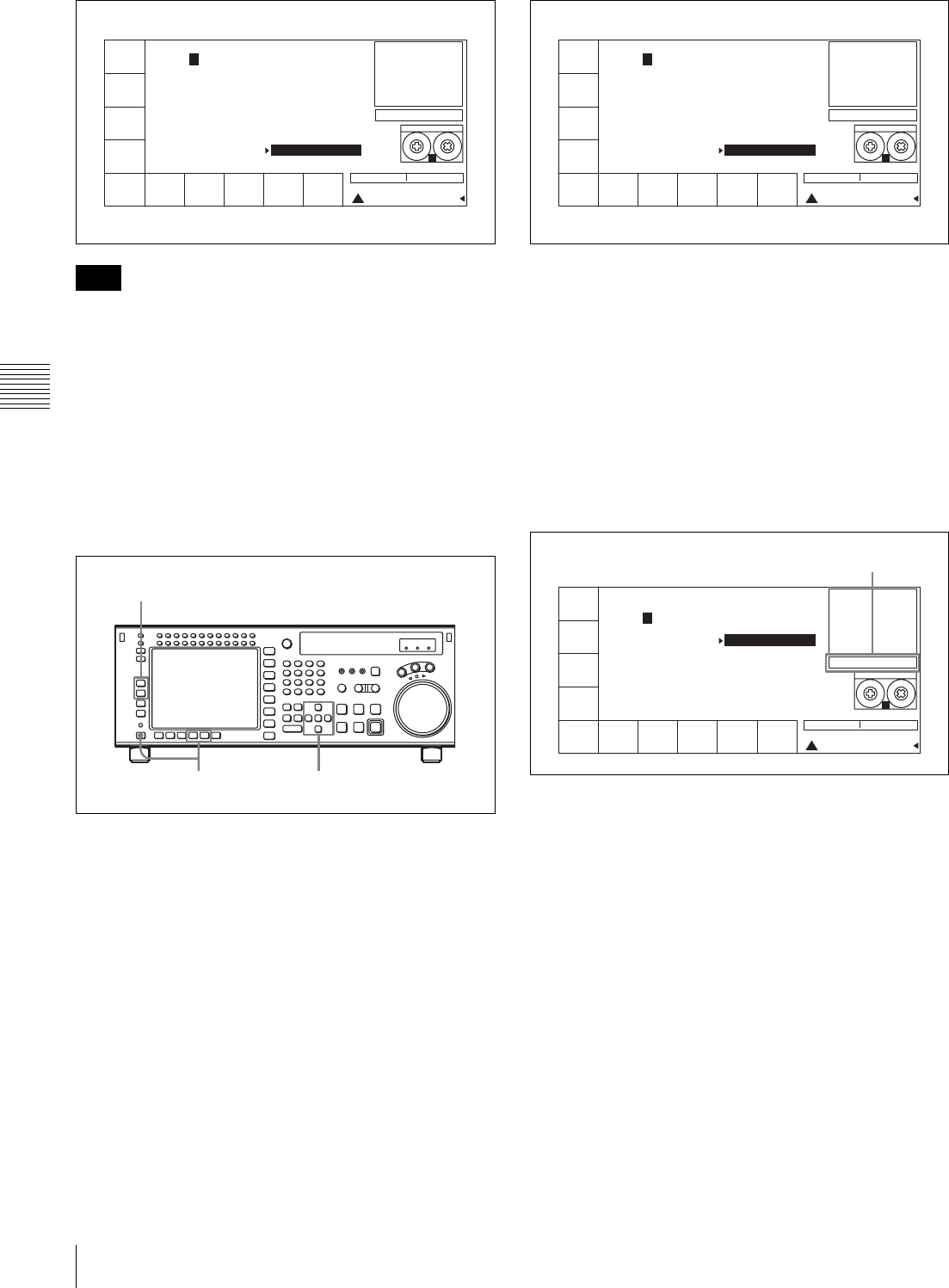
70 4-4 CUE Menu
Chapter 4 Menu Settings
In PAGE mode, the cue number advances only within the
current page when the ENTRY button is pressed
repeatedly. For example, after cue number 19 is registered
and the ENTRY button is pressed, the cue point 10 comes
up as the next cue point. In EXTEND mode, if you press
the ENTRY button after registering, for example, cue
number 99, the next cue point is registered to cue number
99 again.
Registering cue points by the numeric
buttons
1
Press the ALT/[F8] (PAGE MODE) buttons or the
ALT/[F9] (EXTEND MODE) buttons.
2
If you selected PAGE mode, press the [F1] (PREV
PAGE) button or [F2] (NEXT PAGE) button to select
a desired page (or use the numeric buttons to enter the
page number in the data entry window, then press the
[F8] (PAGE SET) button).
3
Press the cursor R or r button to move the cursor (B) to
the cue number to be registered.
To select the cue number directly by the numeric
buttons
Enter the cue number in the data entry window with
the numeric buttons, then press the [F9] (CUENUM
SET) button.
4
Enter the cue point data in the data entry window with
the numeric buttons, then press the SET button.
For example, to enter 00:01:30:00, press 0, 0, 1, 3, 0,
0, 0. (The leading 0 is not required. When the entered
value is less than eight digits, the leading digit(s) is
(are) set to 0 when you press the SET button.)
To modify current cue point data
Press the + or – button, enter the value to be added or
subtracted, then press the SET button.
The computation is performed and the results appear
in the data entry window.
5
Press the ENTRY button to set the entered data.
The data are registered in the cue point data indication.
Note
PREV
PAGE
NEXT
PAGE
TELE
FILE
CUE
P-ROLL
PAGE
SET
CUENUM
SET
M-CUE
CLEAR
STILL
77 77 77 77
[(Blank) ]
PAGE: 0
1
2
3
4
5
6
7
8
9
EOS[--:--:--:--]
0 00:01:10:00
1 00:02:10:00
2 00:03:10:00
3 00:04:10:00
4 00:05:10:00
5 00:06:10:00
6 00:07:10:00
7 00:08:10:00
8 00:09:10:00
9 00:10:10:00 SS
HDCAM-SR
REMAIN:01H06M
! CUE
1 3
2
PREV
PAGE
NEXT
PAGE
TELE
FILE
CUE
P-ROLL
PAGE
SET
CUENUM
SET
M-CUE
CLEAR
STILL
77 77 77 77
[(Blank) ]
PAGE: 0
1
2
3
4
5
6
7
8
9
EOS[--:--:--:--]
0 00:01:10:00
1 00:02:10:00
2 00:03:10:00
3 00:04:10:00
4 00:05:10:00
5 00:06:10:00
6 00:07:10:00
7 00:08:10:00
8 00:09:10:00
9 00:10:10:00 SS
HDCAM-SR
REMAIN:01H06M
! CUE
PREV
PAGE
NEXT
PAGE
TELE
FILE
CUE
P-ROLL
PAGE
SET
CUENUM
SET
M-CUE
CLEAR
STILL
SET-00 13 00 00SET-00 13 00 00
[(Blank) ]
PAGE: 0
1
2
3
4
5
6
7
8
9
EOS[00:13:00:00]
10 00:10:00:00
11 00:11:00:00
12 00:12:00:00
13 00:13:00:00
14 00:14:00:00
15 00:15:00:00
16 00:16:00:00
17 00:17:00:00
18 00:18:00:00
19 00:19:00:00 SS
HDCAM-SR
REMAIN:01H06M
! CUE
Entered data
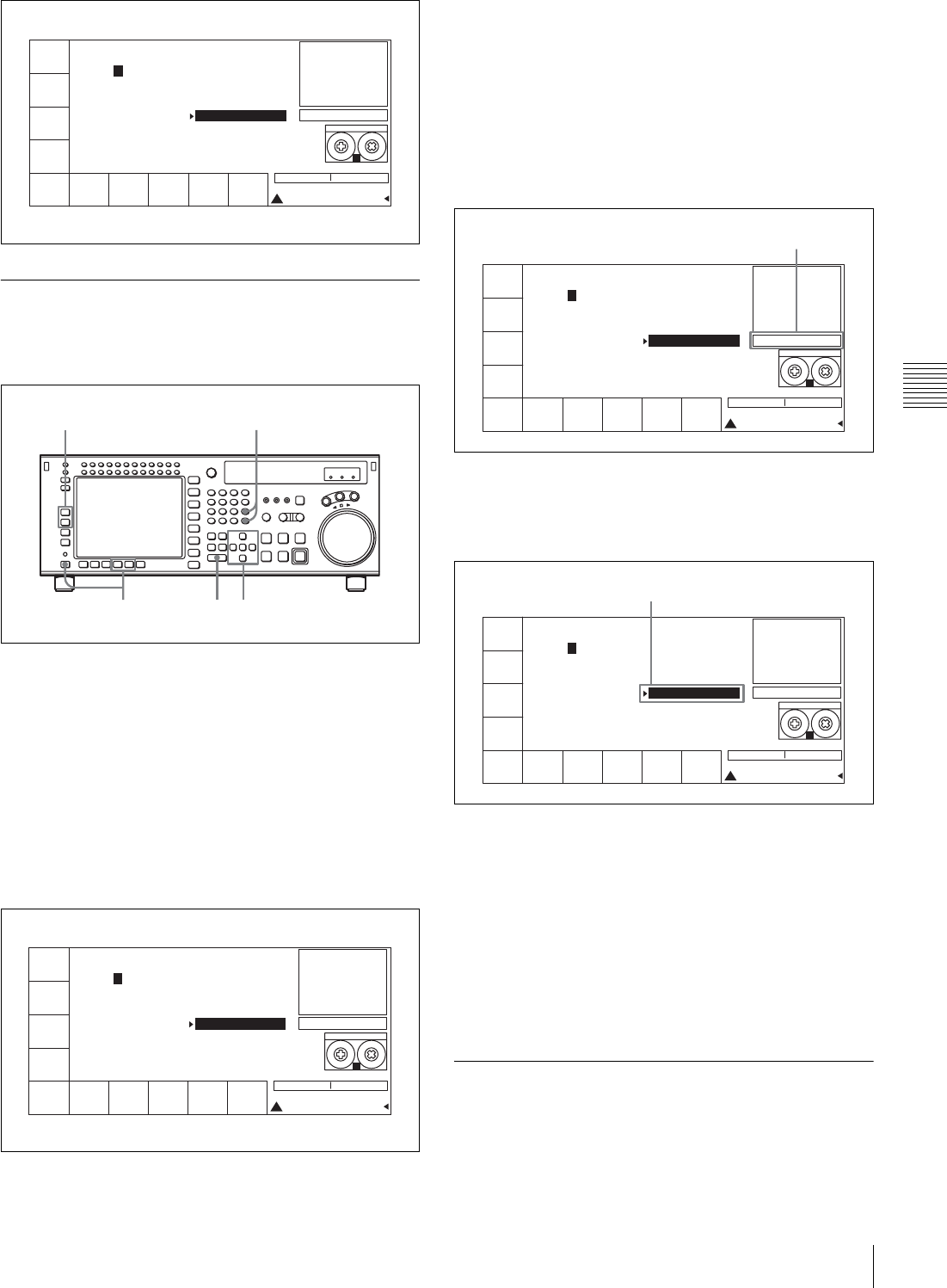
71
4-4 CUE Menu
Chapter 4 Menu Settings
4-4-3 Erasing Cue Point Data
To erase any cue point data, blank out the data entry
window, then do the cue point registration procedure.
1
Press the ALT/[F8] (PAGE MODE) buttons or the
ALT/[F9] (EXTEND MODE) buttons.
2
If you selected PAGE mode, press the [F1] (PREV
PAGE) button or [F2] (NEXT PAGE) button to select
a desired page (or use the numeric buttons to enter the
page number in the data entry window, then press the
[F8] (PAGE SET) button).
3
Press the cursor R or r button to move the cursor (B) to
the cue number to be erased.
To select the cue number directly by the numeric
buttons
Enter the cue number in the data entry window with
the numeric buttons, then press the [F9] (CUENUM
SET) button.
4
Press the CLR button then press the SET button.
The cue point display disappears from the data entry
window.
5
Press the ENTRY button.
Data for the specified cue number are erased and the
data column becomes blank.
To erase all cue point data
Press the CLR button while holding down the SFT
button. A message asking you to confirm the operation
appears in the display.
In EXTEND mode, press the CLR button while
holding down the SFT button again to erase all data for
cue number 0 to 99.
In PAGE mode, press the CLR button while holding
down the SFT button again to erase data for the cue
points on the current page.
4-4-4 Prerolling to a Cue Point
Select the preroll time to a cue point with pressing the [F5]
(CUE P-ROLL) button.
You can set a preroll time of 0 to 30 seconds.
PREV
PAGE
NEXT
PAGE
TELE
FILE
CUE
P-ROLL
PAGE
SET
CUENUM
SET
M-CUE
CLEAR
STILL
[(Blank) ]
PAGE: 0
1
2
3
4
5
6
7
8
9SS
HDCAM-SR
REMAIN:01H06M
! CUE
EOS[00:13:00:00]
10 00:10:00:00
11 00:11:00:00
12 00:12:00:00
13 00:13:00:00
14 00:14:00:00
15 00:15:00:00
16 00:16:00:00
17 00:17:00:00
18 00:18:00:00
19 00:19:00:00
1 35
24
PREV
PAGE
NEXT
PAGE
TELE
FILE
CUE
P-ROLL
PAGE
SET
CUENUM
SET
M-CUE
CLEAR
STILL
SET-01 15 00 00
[(Blank) ]
PAGE: 0
1
2
3
4
5
6
7
8
9SS
HDCAM-SR
REMAIN:01H06M
! CUE
EOS[00:13:00:00]
10 00:10:00:00
11 00:11:00:00
12 00:12:00:00
13 00:13:00:00
14 00:14:00:00
15 00:15:00:00
16 00:16:00:00
17 00:17:00:00
18 00:18:00:00
19 00:19:00:00
PREV
PAGE
NEXT
PAGE
TELE
FILE
CUE
P-ROLL
PAGE
SET
CUENUM
SET
M-CUE
CLEAR
STILL
SET
[(Blank) ]
PAGE: 0
1
2
3
4
5
6
7
8
9SS
HDCAM-SR
REMAIN:01H06M
! CUE
EOS[00:13:00:00]
10 00:10:00:00
11 00:11:00:00
12 00:12:00:00
13 00:13:00:00
14 00:14:00:00
15
16 00:16:00:00
17 00:17:00:00
18 00:18:00:00
19 00:19:00:00
Data entry window
PREV
PAGE
NEXT
PAGE
TELE
FILE
CUE
P-ROLL
PAGE
SET
CUENUM
SET
M-CUE
CLEAR
STILL
[(Blank) ]
PAGE: 0
1
2
3
4
5
6
7
8
9SS
HDCAM-SR
REMAIN:01H06M
! CUE
EOS[00:13:00:00]
10 00:10:00:00
11 00:11:00:00
12 00:12:00:00
13 00:13:00:00
14 00:14:00:00
15 00:15:00:00
16 00:16:00:00
17 00:17:00:00
18 00:18:00:00
19 00:19:00:00
Erased cue point
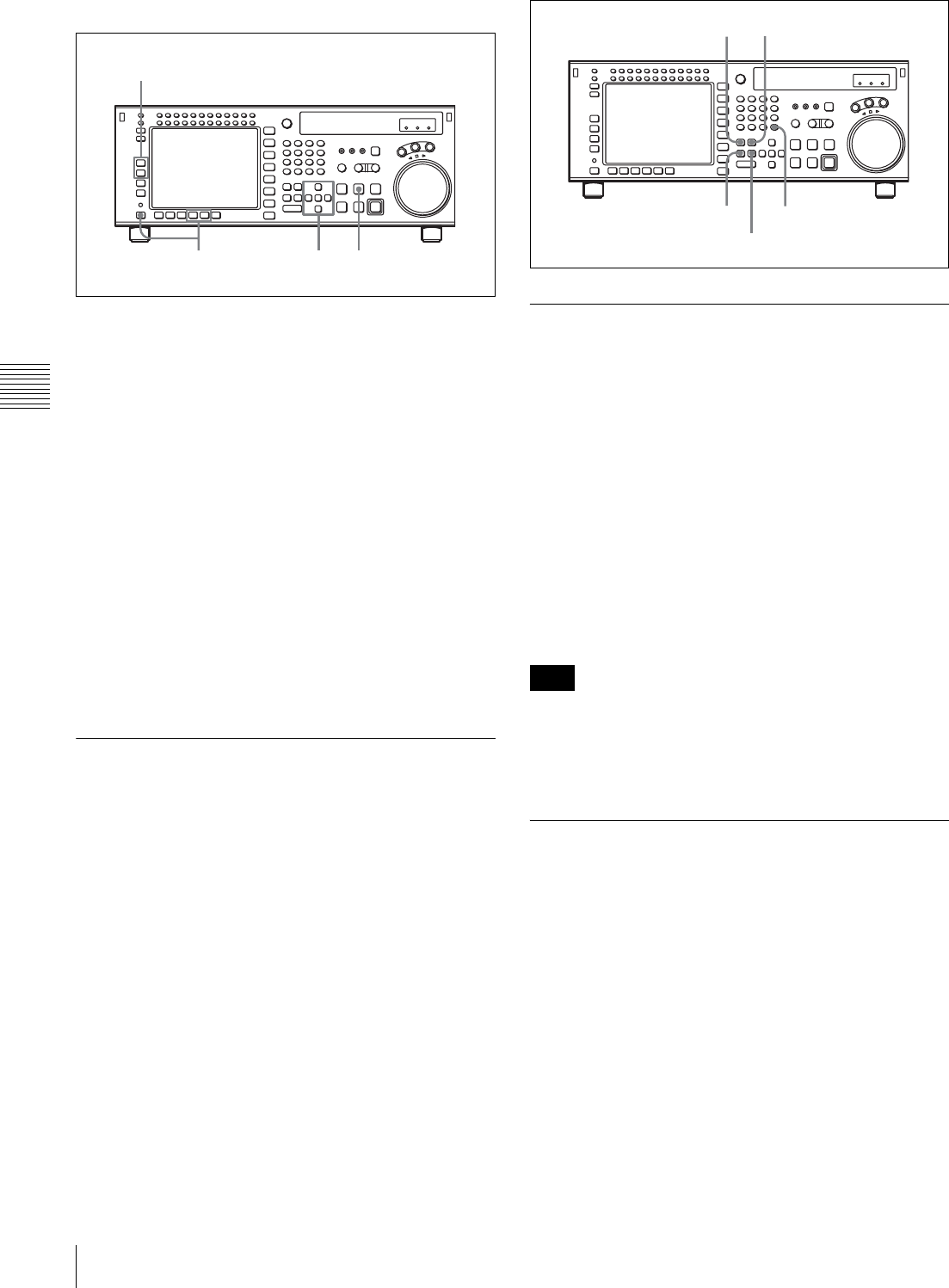
72 4-4 CUE Menu
Chapter 4 Menu Settings
Prerolling to a cue point
1
Press the ALT/[F8] (PAGE MODE) buttons or the
ALT/[F9] (EXTEND MODE) buttons.
2
If you selected PAGE mode, press the [F1] (PREV
PAGE) button or [F2] (NEXT PAGE) button to select
a desired page (or use the numeric buttons to enter the
page number in the data entry window, then press the
[F8] (PAGE SET) button).
3
Press the cursor R or r button to move the cursor (B) to
the cue number.
To select the cue number directly by the numeric
buttons
Enter the cue number in the data entry window with
the numeric buttons, then press the [F9] (CUENUM
SET) button.
4
Press the PREROLL button.
4-4-5 Changing a Cue Point Into an
Edit Point
Follow the procedures below to change a selected cue
point into an edit point.
To change an edit point into an IN point
Press the SET button while holding down the IN button.
To change an edit point into an OUT point
Press the SET button while holding down the OUT button.
To change an edit point into an AUDIO IN point
Press the SET button while holding down the AUDIO IN
button.
To change an edit point into an AUDIO OUT point
Press the SET button while holding down the AUDIO
OUT button.
4-4-6 Backspace Editing
You can perform backspace editing with the CUE menu. In
backspace editing, assemble editing is performed from the
recording end point. Thus, before starting backspace
editing for the first time, you must record for at least one
minute or so on the tape before you can do backspace
editing. After recording, the present end of the recorded
portion becomes the recording end point. When you press
the AUTO button and then press the REC/EDIT button, the
VTR automatically prerolls a few seconds before the
recording end point and starts assemble editing. If no data
for the recording end point exist, backspace editing is not
performed.
The recording end point will be cleared when you eject the
tape.
Cue point data is cleared when a cassette is inserted.
However, cue point data recalled from a memory stick
before a cassette is inserted is not cleared when a cassette
is inserted.
4-4-7 TELE FILE Menu
The TELE FILE menu screen is different in HDCAM-SR
and HDCAM formats.
In HDCAM-SR format: The cassette has a memory label
attached as standard, and this screen allows
operations to read out, enter, or change the cassette ID
identification, recording format, recording
information, management information, and so on. In
the HDCAM-SR format, each recording
automatically adds recording information. However,
if the recording time is less than 2 seconds, or if when
recording ends the measurement on the spool was not
complete, then no recording information is added. In
the case of an HDCAM-SR cassette, a cassette
without a memory label is ejected.
134
2
Note
AUDIO IN button AUDIO OUT button
IN button SET button
OUT button
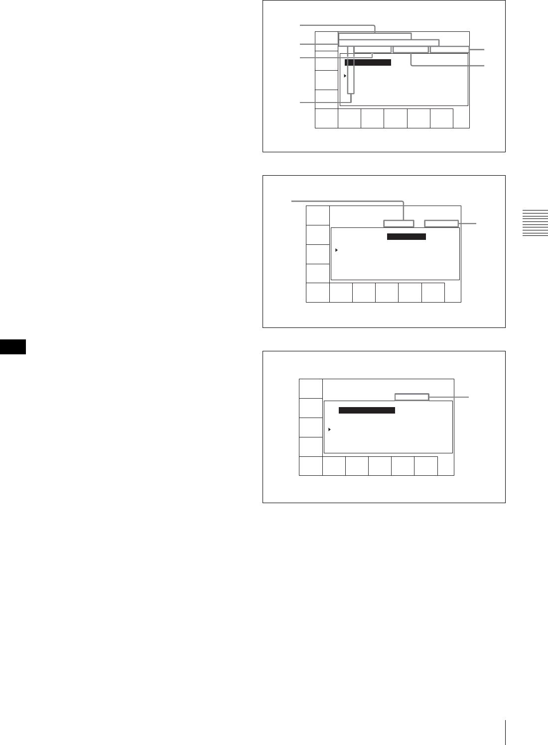
73
4-4 CUE Menu
Chapter 4 Menu Settings
In HDCAM format: When an MLB-1M-100 memory
label (optional) is attached to the cassette, this screen
allows operations to read out, enter, or change the cue
point information, log (IN/OUT point) information,
management information, and so on. Using this
information, cassette tape management and tape
editing efficiency can be improved.
HDCAM-SR format TELE FILE menu
To open the TELE FILE menu
There are two methods of accessing the TELE FILE menu
screen, as follows.
• Press the [F4] (TELE FILE) button while in the CUE
menu.
• Select “on” for the VTR SETUP menu item 124 “Tele-
File MENU auto popup”. Then, with the HOME, TC,
VIDEO, AUDIO, CUE, or SETUP menu open, insert a
cassette into the VTR.
To change the information displayed in the TELE
FILE menu
Press the cursor T or t button.
Exiting the TELE FILE menu
Press the [F10] (WRITE/EXIT) button. The entered or
modified data is saved to the memory label and the VTR
exits the TELE FILE menu.
While the data is being changed, if the write-protect setting
has been made for the whole TELE FILE menu, then data
changed before the setting was made is rewritten.
To exit the TELE FILE menu without saving data
to a memory label
Press the EJECT button, or press the ALT/[F2] (UNDO
ALL) buttons. After a window that confirms cancelation is
displayed, hold down the SFT button, and press the [F2]
(UNDO ALL) button. The memory label contents when
the cassette was inserted are restored.
If you accidentally press the EJECT button before
saving data to a memory label
Insert the cassette again within 30 seconds after the
ejection and press the [F10](WRITE/EXIT) button. The
data that existed before the ejection of the cassette is saved
to the memory label.
Three levels of information can be displayed in the TELE
FILE menu and the levels can be scrolled to the left or right
by pressing the T or t button.
TELE FILE menu display 1
TELE FILE menu display 2
TELE FILE menu display 3
aTape Format
Displays the recording format.
bOUT
Displays the recording end point data.
cIN
Displays the recording start point data.
dTITLE
Displays the cassette title.
Note
CUE
SCAN
ENTRY
POINT
CUE
COMMNT
EDIT
CHANGE
DATA
DEL
POINT
PRO-
TECT
TAPE
INFO
CUENUM
POINT
WRITE/
EXIT
MARK
REC DATE[2003/02/25 ]
TITLE[Display Sample
No. IN OUT
1 00:03:45:21 01:00:36:06 59i 1080
2 01:04:27:23 01:05:31:24 59i 1080
3 01:08:11:03 01:09:48:20 60i 720
4 00:00:00:01 01:00:36:06 23p 1080
5 00:00:00:01 01:00:36:06 23i 1080
EOS[01:01:24:15]
] Rest 87%
Tape Format
5
4
3
1
2
Line
number
CUE
SCAN
ENTRY
POINT
CUE
REC DATE[2003/02/25 ]
TITLE[Display Sample
No. Tape Format Duration
1 59i 1080 422 01:00:36:06 --------
2 59i 1080 422 00:01:25:08 --------
3 60p 720 422 00:02:36:45 --------
4 23p 1080 422 01:00:36:06 02/08/08
5 23p 1080 422 01:00:36:06 02/08/08
EOS[01:01:24:15]
] Rest 87%
Date/Time
COMMNT
EDIT
CHANGE
DATA
DEL
POINT
PRO-
TECT
TAPE
INFO
CUENUM
POINT
WRITE/
EXIT
MARK
7
6
CUE
SCAN
ENTRY
POINT
CUE
REC DATE[2003/02/25 ]
TITLE[Display Sample
No. Data/Time
1 -------- -------- HDCAMSR_000
2 -------- -------- HDCAMSR_001
3 -------- -------- HDCAMSR_002
4 02/08/08 13:21:09 test
5 02/08/08 13:24:27 HDCAMSR_011
EOS[01:01:24:15]
] Rest 87%
File Name
COMMNT
EDIT
CHANGE
DATA
DEL
POINT
PRO-
TECT
TAPE
INFO
CUENUM
POINT
WRITE/
EXIT
MARK
8
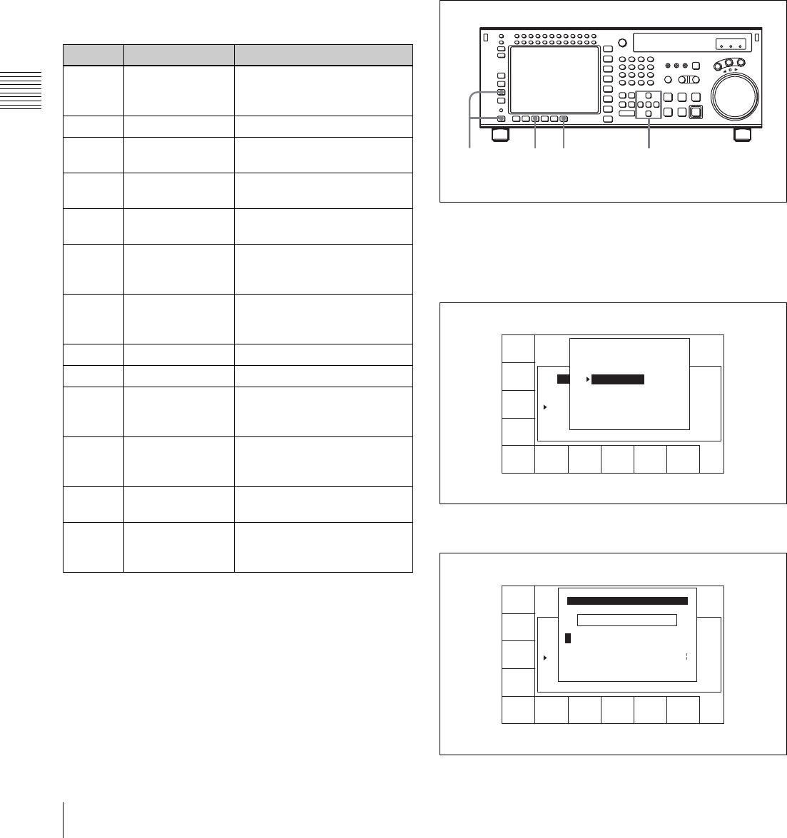
74 4-4 CUE Menu
Chapter 4 Menu Settings
eREC DATE
Displays the date the memory label contents were last
modified.
fDate/Time
Displays the recording date and time.
gDuration
Displays the recording duration.
hFile Name
Displays the names of files.
When the TELE FILE menu display 2 is displayed, you
can press the SFT button to switch the TAPE FORMAT
display between “59i 1080 422” and “59i 4:2:2 SQ”.
Formatting a memory label
1
Press the ALT/[F1] (FORMAT T-Fil) buttons.
2
Press the [F1] (FORMAT T-Fil) button while holding
down the SFT button.
A message appears (in the control panel display)
requesting confirmation of the formatting operation.
To cancel the formatting operation
Press the CLR button.
3
Press the [F1] (FORMAT T-Fil) button while holding
down the SFT button.
“COMPLETED” appears in the control panel display.
Prohibiting TELE FILE menu operations
Press the ALT/[F7] (WRITE PRTEC) buttons.
on: All TELE FILE menu operations are prohibited.
off: All TELE FILE menu operations are permitted.
Changing a title
1
Press the ALT/[F3](ATTRIB EDIT) buttons.
2
Press the R or r button to select TITLE, and then press
the ENTRY button.
3
Press the cursor T or t button to select a character.
Button Indication Function
[F1] CUE SCAN Specifies the direction of the
cursor movement when the
PREROLL button is pressed.
[F4] CHANGE DATA Modifies the specified data.
[F5] DEL POINT Deletes the time data of the
cue point.
[F7] PROTECT Write-protects the cue point
data.
[F8] TAPE INFO Displays the information
window.
[F9] CUENUM POINT Moves the cursor to the line
specified by the numeric
buttons.
[F10] WRITE/EXIT Closes the TELE FILE menu
after saving changes to the
memory label.
ALT/[F1] FORMAT T-Fil Formats the memory label.
ALT/[F2] UNDO ALL Undoes all changes.
ALT/[F3] ATTRIB EDIT Changes the ID, ADMIN, or
TITLE data in the information
window.
ALT/[F4] COPY to CUE Copies the time data of a cue
point to another cue point
indicated in the CUE menu.
ALT/[F7] WRITE PRTEC Prohibits TELE FILE menu
operations.
ALT/[F10] WRITE/EXIT Closes the TELE FILE menu
after saving changes to the
memory label.
2,364
1
FORMAT
T-Fil
UNDO
ALL
ATTRIB
EDIT
COPY
toCUE
T-Fil
MODE
panel
WRITE
PRTEC
off
REC DATE[2003/02/25]
TITLE[ isplay Sample
No. Tape Format Duration
0 59i 1080 422 01:00:36:06 --------
1 59i 1080 422 01:00:36:06 --------
2 59i 1080 422 00:01:25:08 --------
3 60p 720 422 00:02:36:45 --------
EOS[01:01:--:--]
] Rest 95%
Date/Time
ATTRIB EDIT SELECT
TITLE
ID
ADMIN
Press [ENTRY] to edit
Press [CLR] to CANCEL
SPACE SET
LETTER
CANCEL SAVE/
EXIT
BACK
SPACE
REC DATE[2003/02/25]
TITLE[ isplay Sample
No. Tape Format Duration
0 59i 1080 422 01:00:36:06 --------
1 59i 1080 422 01:00:36:06 --------
2 59i 1080 422 00:01:25:08 --------
3 60p 720 422 00:02:36:45 --------
EOS[01:01:--:--]
] Rest 95%
Date/Time
_ ->
ABCDEFGHIJKLMNOPQRSTUVWXYZ
abcdefghjiklmnopqrstuvwxyz
0123456789[]()<>@+-*=!?:;
EDIT TITLE
$#%&,."\^_'/~ {} HD1D2CAM
'
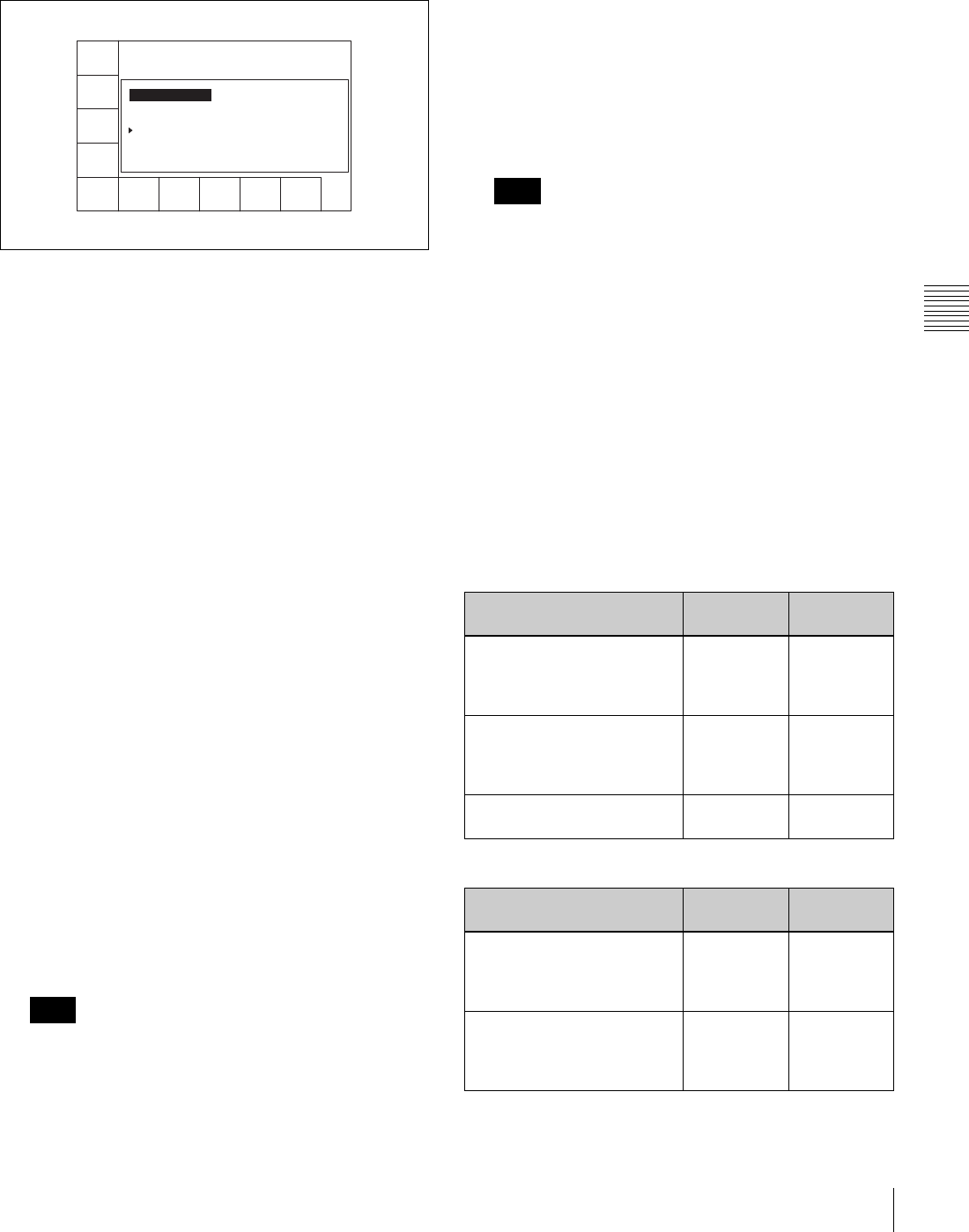
75
4-4 CUE Menu
Chapter 4 Menu Settings
4
Press the [F7] (SET LETTER) button or the cursor
center button.
The selected character is entered.
5
Repeat steps 3 and 4 to enter more characters.
To enter a space
Press the [F5] (SPACE) button.
If you enter a wrong character
Press the [F6] (BACK SPACE) button to go back.
Then re-enter the character.
To start the procedure over again
Press the [F9] (CANCEL) button to start again.
To change a character
Press the cursor R button to move the cursor to the title
box. Then press the cursor T or t button to change
the insertion position.
If entered title exceeds the length of the title box
t or T appears to the left or right of the box.
6
Press the [F10] (SAVE/EXIT) button.
The screen that was on before the title was entered is
displayed again.
To change IN/OUT point time data
1
Use the cursor buttons to move the cursor (B) to the
line where you want to change IN/OUT point time
data.
To move the cursor using the numeric buttons
With the cursor specifying IN or OUT, enter the line
number using the numeric buttons. Then press the [F9]
(CUENUM POINT) button. The cursor will move to
the line specified by the numeric buttons.
If the cursor (B) is not linked with the cursor buttons,
the cursor (B) will not move when the cursor buttons
are pressed.
To link the cursor (B) with the cursor buttons
Press the cursor center button. Each press of the button
alternately links and unlinks the cursor B.
2
Press the ENTRY button.
When the cursor buttons are aligned with the IN point,
and the IN point is at the OUT point, when you press
the ENTRY button at the OUT point, the time code is
either entered as a new value or updated. To update the
data, the winding diameter measurement must be
completed, and the drum locked, and then the tape
information read in.
If the cursor (B) is not on the screen when the ENTRY
button is pressed, the time data on the line currently
specified by the cursor (B) changes to the current time
data, and the line is automatically displayed.
To clear the data
With the cursor buttons, align the cursor with the data you
want to clear, and in the case of the IN point hold down the
IN button, and in the case of the OUT point hold down the
OUT button, and press the CLR button, to clear the data.
You can also clear the data by holding down the CLR
button, and pressing the IN button or OUT button.
Effect on other data of data entry or update
When you enter or update the IN point or OUT point, other
data is updated as shown in the following table.
IN point entry/update:
OUT point entry/update:
Note
REC DATE[2003/02/25]
TITLE[SONY
No. IN OUT
0 00:00:04:05 00:00:09:23 59i 1080
1 00:03:45:21 01:00:36:06 59i 1080
2 01:04:27:23 01:05:31:24 59i 1080
3 --:--:--:-- --:--:--:-- --- ----
EOS[--:--:--:--]
] Rast 85%
Tape Format
FORMAT
T-Fil
UNDO
ALL
ATTRIB
EDIT
COPY
toCUE
T-Fil
MODE
panel
WRITE
PRTEC
off
WRITE
EXIT Note
State of the already-entered
data
IN point OUT point
The already-entered OUT
point data and entered or
updated IN point data are in
the correct time sequence
Data is
updated
Data is not
updated
The already-entered OUT
point data and entered or
updated IN point are not in
the correct time sequence
Data is
updated
Data is
deleted
OUT point data has not been
entered
Data is
updated
Data is not
updated
State of the already-entered
data
IN point OUT point
The already-entered IN point
data and entered or updated
OUT point data are in the
correct time sequence
Data is not
updated
Data is
updated
The already-entered IN point
data and entered or updated
OUT point are not in the
correct time sequence
Data is not
updated
Data is not
updated

76 4-4 CUE Menu
Chapter 4 Menu Settings
Updating File Name data
To update File Name data, press the cursor t button
several times.
To update data
1
With the cursor buttons, align the cursor with the File
Name data you want to update.
To move the cursor with the numeric buttons
Enter a line number with the numeric buttons, and
press the [F9] (CUENUM POINT) button. The cursor
moves to the line number you entered.
2
Press the [F4] (CHANGE DATA) button.
3
With the cursor T or t button, select the character
to be entered.
4
Press the [F7] (SET LETTER) button or cursor center
button.
The selected character is entered.
5
Repeat steps 3 and 4, to enter the data.
A maximum of 15 characters can be entered.
Note
If the number of entered characters is too large, a
memory overflow may occur, and it may become
impossible to enter other cue point data. Press the [F8]
(TAPE INFO) button to check the free memory
capacity.
To enter a space
Press the [F5] (SPACE) button, then carry out entry.
If you make an error in entry
Press the [F6] (BACK SPACE) button, then carry out
entry.
Canceling and repeating the process
Press the [F9] (CANCEL) button, then carry out entry.
To change a character during the operation
Press the cursor R button, then move the cursor to the
comment frame. With the cursor T button or t
button, change the character insertion position.
6
Press the [F10] (SAVE/EXIT) button.
This returns to the original menu screen.
Cueing up to the IN point
1
Hold down the [F1] (CUE SCAN) button, and press
the PREROLL button. This sets the cursor movement
direction.
Each press cycles through the settings FWD/REW/No
setting.
FWD: Pressing the PREROLL button moves the
cursor to the next line, and cues up to the time data
of that line. Invalid time data is ignored.
REW: Pressing the PREROLL button moves the
cursor to the previous line, and cues up to the time
data of that line. Invalid time data is ignored.
2
Press the PREROLL button.
To write-protect the cue point data
To write-protect individual cue point data items, align the
cursor with the line you want to write-protect, then press
the [F7] (PROTECT) button. When appears to the right
of “No.”, then it is not possible to change the IN, OUT, and
File Name settings.
Canceling the write-protect setting
To cancel the write-protect setting, press the [F7]
(PROTECT) button. After a confirmation message
appears, hold down the SFT button and press the [F7]
(PROTECT) button.
To insert a new line
1
Use the cursor buttons to position the cursor (B) below
the line where a new line will be inserted.
To move the cursor with the numeric buttons
To move the cursor, enter a line number with the
numeric buttons, then press the [F9] (CUENUM
POINT) button. The cursor moves to the line number
you entered.
If the cursor buttons are not linked to movement of the
entry cursor B, it is not possible to move the entry
cursor B with the cursor buttons.
To link the cursor buttons to movement of the entry
cursor B
Press the cursor center button. To unlink, press the
cursor center button once again.
2
Press the ENTRY button while pressing down the SFT
button.
A new line is inserted above the line specified by
where the cursor (B) is placed and the current time
data is entered on that line.
IN point data has not been
entered
Data is not
updated
Data is
updated
State of the already-entered
data
IN point OUT point
Note
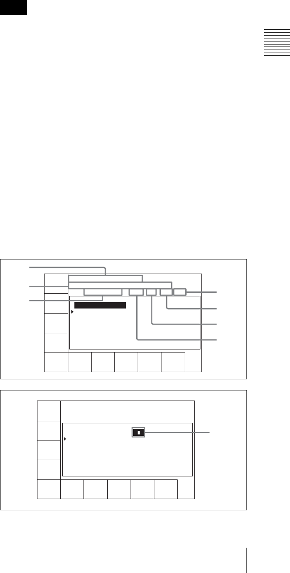
77
4-4 CUE Menu
Chapter 4 Menu Settings
To delete a line
To delete a line, with the cursor buttons align the cursor
with the line to be deleted, hold down the SFT button, and
press the [F5] (DEL POINT) button. This deletes the line,
and renumbers the lines following the deleted line.
To display other information
To display other information, press the [F8] (TAPE INFO)
button. This opens a window to display the information.
To close the window
Press the [F8] (TAPE INFO) button.
To change the ID/ADMIN data
1
Press the ALT/[F3] (ATTRIB EDIT) buttons.
2
With the cursor R or r button, select “ID” or
“ADMIN”, then press the ENTRY button.
3
With the cursor T or t button, select the character
to be entered.
4
Press the [F7] (SET LETTER) button or cursor center
button.
The selected character is entered.
5
Repeat steps 3 and 4, to enter the data.
To enter a space
Press the [F5] (SPACE) button.
If you make an error in entry
Press the [F6] (BACK SPACE) button, then carry out
entry.
Returning to the original settings
Press the [F9] (CANCEL) button, then carry out entry.
To change a character during the operation
Press the cursor R button, then move the cursor to the
ID or ADMIN frame. With the cursor T or t button,
change the character insertion position.
When not all characters can be shown within the ID
or ADMIN frame
On the left or right of the comment frame, t or T
appears.
6
Press the [F10] (SAVE/EXIT) button.
This returns to the original screen.
HDCAM format TELE FILE menu
Accessing the TELE FILE menu screen
There are two methods of accessing the TELE FILE menu
screen, as follows.
• In the CUE menu screen, press the [F4] (TELE FILE)
button.
• Set the VTR SETUP menu item 124 “Tele-File MENU
auto popup” to “on”, then in the HOME, VIDEO,
AUDIO, TC, CUE, or SETUP menu screen, insert a
cassette that has an MLB-1M-100 memory label
(option) attached.
To scroll the TELE FILE menu screen horizontally
Press the cursor T or t button.
There are two ways of displaying log (IN/OUT point) data
in the TELE FILE menu screen, as follows.
• In the TELE FILE menu screen, press the [F2] (ENTRY
POINT) button, and select “IN/OUT point”.
• Set the VTR SETUP menu item 126 “Tele-File ENTRY
POINT” to “IN/OUT point”.
While the data is being changed, if the write-protect setting
has been made for the whole TELE FILE menu, then data
changed before the setting was made is rewritten.
To exit the TELE FILE menu without overwriting
the changed point(s)
Press the EJECT button, or press the ALT/[F2] (UNDO
ALL) buttons. After a window that confirms cancelation is
displayed, hold down the SFT button, and press the [F2]
(UNDO ALL) button. The memory label contents when
the cassette was inserted are restored.
If you inadvertently press the EJECT button
without rewriting the data
Reinsert the ejected cassette within 30 seconds, and press
the [F10] (WRITE/EXIT) button. This writes the data from
immediately before ejection.
The TELE FILE menu screen scrolls in the following four
stages. Scroll the screen with the cursor T or t button.
Note
CUE
SCAN
ENTRY
POINT
CUE
COMMNT
EDIT
CHANGE
DATA
DEL
POINT
PRO-
TECT
TAPE
INFO
CUENUM
POINT
WRITE/
EXIT
MARK
REC DATE[2003/02/25] EOS[01:01:24:15]
TITLE[ ] Rast100%
No. Time Mrk Tk Cut Scn
0 00:14:10:10
1 --:--:--:--
1
2
3
0
9
8
4
CUE
SCAN
ENTRY
POINT
CUE
COMMNT
EDIT
CHANGE
DATA
DEL
POINT
PRO-
TECT
TAPE
INFO
CUENUM
POINT
WRITE/
EXIT
MARK
REC DATE[2003/02/25] EOS[01:01:24:15]
TITLE[ ] Rast100%
No. Time Mrk Tk Cut Scn
0 00:14:10:10
1 --:--:--:--
5
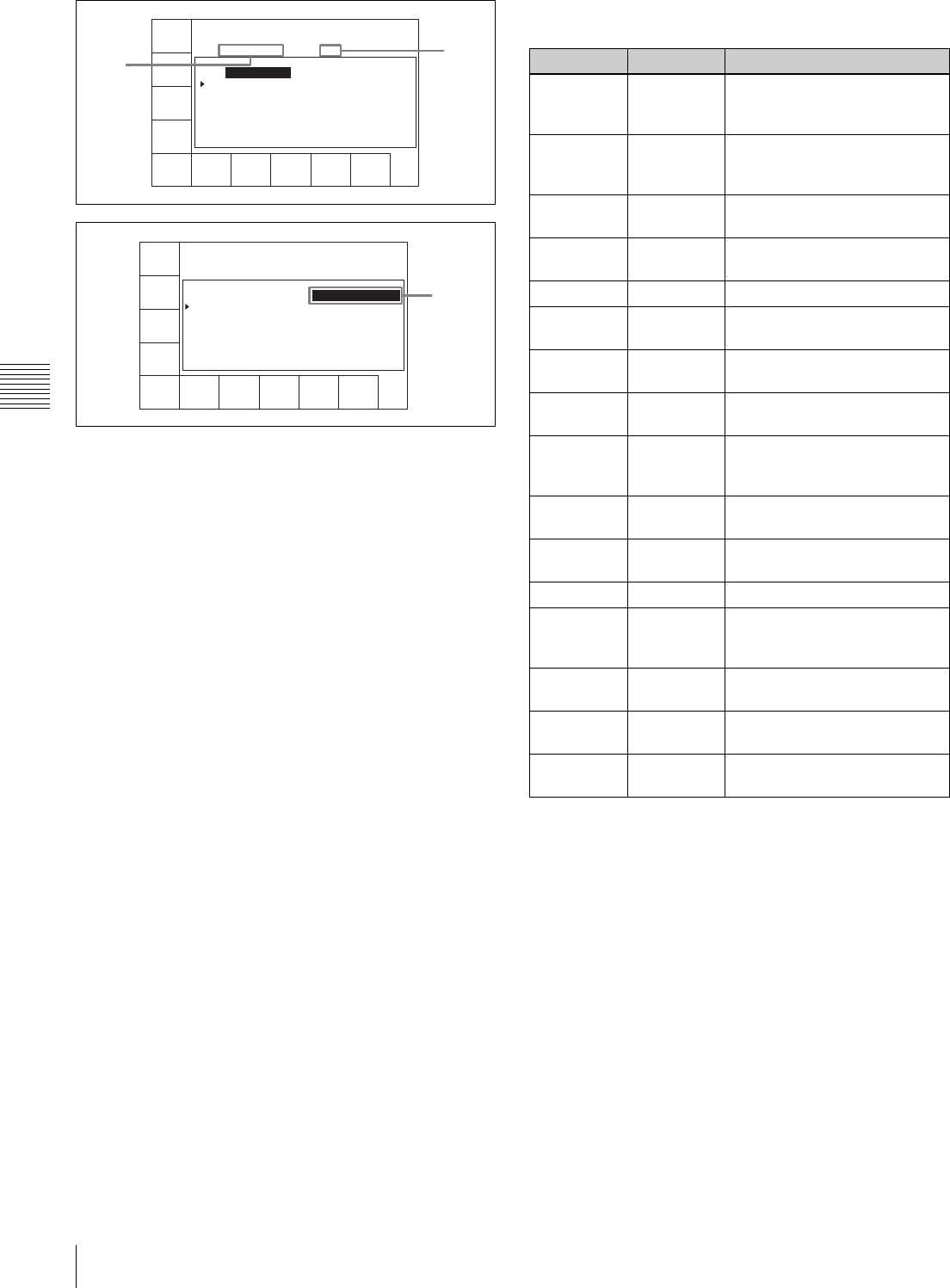
78 4-4 CUE Menu
Chapter 4 Menu Settings
aREC DATE (recording data date)
Shows the last date of recording.
bTITLE
Shows the title of the cassette content.
cTime
Shows the time data of a cue point.
dMrk (mark)
Shows an indication of a cue point attribute (OK/NG/KP/
blank).
eRecording start point
When a cue point is the recording start point, shows @.
For how to select “on” or “off” for the recording starting
point setting, see “Changing the recording starting point
setting” on page 80.
fIN
Shows log (IN point) data.
gOUT
Shows log (OUT point) data.
hTk (take)
Shows the take number of a cue point.
iCut
Shows the cut number of a cue point.
jScn (scene)
Shows the scene number of a cue point.
kComment
Shows a comment on a cue point.
To format a memory label
1
Press the ALT/[F1] (FORMAT T-Fil) buttons.
2
Hold down the SFT button, and press the [F1]
(FORMAT T-Fil) button.
A confirmation window appears.
To cancel
Press the CLR button.
3
Hold down the SFT button, and press the [F1]
(FORMAT T-Fil) button.
“COMPLETED” appears.
To set write protection for the whole menu
Press the ALT/[F7] (WRITE PRTEC) buttons.
on: Set write protection for the whole TELE FILE menu.
CUE
SCAN
ENTRY
POINT
INOUT
COMMNT
EDIT
CHANGE
DATA
DEL
POINT
PRO-
TECT
TAPE
INFO
CUENUM
POINT
WRITE/
EXIT
MARK
REC DATE[2003/02/25] EOS[01:01:24:15]
TITLE[ ] Rast100%
No. In Out
0 00:14:16:05 00:14:17:02
1 --:--:--:-- --:--:--:--
6
7
CUE
SCAN
ENTRY
POINT
CUE
COMMNT
EDIT
CHANGE
DATA
DEL
POINT
PRO-
TECT
TAPE
INFO
CUENUM
POINT
WRITE/
EXIT
MARK
REC DATE[2003/02/25] EOS[01:01:24:15]
TITLE[ ] Rast100%
No. Time Mrk Comment
0 00:14:10:10
1 --:--:--:--
qa
Button Indication Function
[F1] CUE SCAN Sets the cursor movement
direction when the PREROLL
button is pressed.
[F2] ENTRY
POINT
Selects whether or not to
display log (IN/OUT point)
information.
[F3] COMMNT
EDIT
Edits the Comment box.
[F4] CHANGE
DATA
Changes the value of data.
[F5] DEL POINT Deletes time data.
[F6] MARK Changes the setting in the Mrk
box.
[F7] PROTECT Prevents the cue point data
from being changed.
[F8] TAPE INFO Shows information on the
memory label.
[F9] CUENUM
POINT
Moves the cursor to the line
number entered with the
numeric buttons.
[F10] WRITE/
EXIT
Saves the changes and exits
the TELE FILE menu.
ALT/[F1] FORMAT T-
Fil
Formats a memory label.
ALT/[F2] UNDO ALL Cancels all changes.
ALT/[F3] ATTRIB
EDIT
Changes the ID, ADMIN, and
TITLE within the tape
information window.
ALT/[F4] COPY to
CUE
Copies time data to the CUE
menu screen cue point data.
ALT/[F7] WRITE
PRTEC
Sets or unsets write protection
of the whole TELE FILE menu.
ALT/[F10] WRITE/
EXIT
Saves the changes and exits
the TELE FILE menu.

79
4-4 CUE Menu
Chapter 4 Menu Settings
off: Clear write protection for the whole TELE FILE
menu.
To change the TITLE data
1
Press the ALT/[F3] (ATTRIB EDIT) buttons.
2
With the cursor R or r button, select “TITLE”, and
press the ENTRY button.
3
With the cursor T or t button, select the character
to be entered.
4
Press the [F7] (SET LETTER) button or cursor center
button.
The selected character is entered.
5
Repeat steps 3 and 4, to enter the data.
To enter a space
Press the [F5] (SPACE) button.
If you make an error in entry
Press the [F6] (BACK SPACE) button, then repeat the
entry.
To return to the initial screen
Pressing the [F9] (CANCEL) button returns to the
initial screen.
To change a character during the operation
Press the cursor R button, then move the cursor to the
title frame; with the cursor T or t button, change
the character insertion position.
When not all characters can be shown within the
title frame
On the left or right of the title frame, < or ,
appears.
6
Press the [F10] (SAVE/EXIT) button.
This return to the initial menu screen.
To change time data
To write the current time data, use the cursor buttons to
align the entry cursor with the line in which you want to
write.
To move the cursor with the numeric buttons
Enter a line number with the numeric buttons, and
press the [F9] (CUENUM POINT) button. The cursor
moves to the line number you entered.
If the cursor buttons are not linked to movement of the
entry cursor, it is not possible to move the entry cursor
B with the cursor buttons.
To link the cursor buttons to movement of the entry
cursor
Press the cursor center button. To unlink, press the
cursor center button once again.
Press the ENTRY button to write the current time data
over the time data in the line in which the entry cursor
B is present.
If you press the ENTRY button when the entry cursor is
not on the screen, the time data of the line in which the
entry cursor B is currently present is written and displayed
on the screen.
To enter the current time data as a new line
1
With the cursor buttons, move the entry cursor to the
line below the position in which you want to insert.
For how to move the cursor, see “To change time
data” above.
2
Hold down the SFT button and press the ENTRY
button.
The line is inserted immediately before the line on
which the entry cursor is present, and the current time
data is written.
To delete a time code
1
Use the cursor buttons to move the cursor to the Time
section to be deleted.
To move the cursor using the numeric buttons
Enter the line number using the numeric buttons. Then
press the [F9] (CUENUM POINT) button. The cursor
will move to the line specified by the numeric buttons.
2
Press the [F5] (DEL POINT) button.
A deletion confirmation window appears.
3
Press the [F5] (DEL POINT) button while holding
down the SFT button.
The time code section becomes blank and is ready for
new time data input.
To delete the line as well as the time code
Use the cursor buttons to move the cursor to the time
code to be deleted.
Then press the [F5] (DEL POINT) button while
holding down the SFT button. The line is deleted and
all the line numbers below are decreased by one.
Note
Note
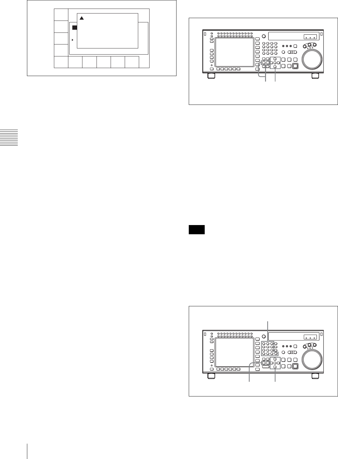
80 4-4 CUE Menu
Chapter 4 Menu Settings
To undo the deletion of a time data or line
Press the ALT/[F2] (UNDO ALL) buttons.
A message appears (in the control panel display)
requesting confirmation of the undo operation.
Press the [F2] (UNDO ALL) button while holding
down the SFT button. To cancel the undo operation,
press the CLR button.
To copy time data of a cue point to another cue
point specified in the CUE menu
1
Press the ALT/[F4] (COPY to CUE) buttons.
A copy confirmation window appears.
To cancel the copy operation
Press the CLR button.
2
Press the [F4] (COPY to CUE) button while holding
down the SFT button.
The time data of the cue point is copied to the cue point
indicated in the CUE menu.
Changing Mrk data
Use the cursor buttons to move the cursor to the line with
the mark attribute to be changed, and then press the [F6]
(MARK) button. Or, move the cursor directly to the mark
attribute to be changed, and then press the [F4] (CHANGE
DATA) button. In both cases, each press of the button
changes the attribute as follows: OK t NG t KP
(KEEP) t blank (no attribute).
Changing the recording starting point setting
Use the cursor buttons to move the cursor to the recording
starting point section. Then press the [F4] (CHANGE
DATA) button. Each press of the button turns the setting
“on” (the @ indication appears) or “off” (the indication
disappears).
Entering and modifying IN/OUT point data
You can use either the ENTRY button or the numeric
buttons to enter and modify IN/OUT point data.
To enter or modify IN/OUT point data using the
ENTRY button
1
Use the cursor buttons to move the cursor to the IN/
OUT section on which the current log data is to be
entered or modified.
To move the cursor using the numeric buttons
Enter the line number using the numeric buttons. Then
press the [F9] (CUENUM POINT) button. The cursor
will move to the line specified by the numeric buttons.
2
Press the IN button (to enter IN point data) or OUT
button (to enter OUT point data) while holding down
the ENTRY button.
The current time code is entered as the IN/OUT point
data or it replaces the existing IN/OUT point data.
If the cursor is not on the IN/OUT section when pressing
the IN or OUT button while pressing down the ENTRY
button, the current cue point is entered or it replaces the
existing cue point. When pressing the ENTRY button only,
the cue point is entered or replaced regardless of the cursor
position.
To enter or modify IN/OUT point data using the
numeric buttons
1
Use the cursor buttons to move the cursor to the IN/
OUT section to be entered or modified.
REC DATE[2003/02/25]
TITLE[SONY
No. IN OUT
0 00:00:04:05 00:00:09:23 59i 1080
1 00:03:45:21 01:00:36:06 59i 1080
2 01:04:27:23 01:05:31:24 59i 1080
3 --:--:--:-- --:--:--:-- --- ----
EOS[--:--:--:--]
] Rest 85%
Tape Format
CUE
SCAN
ENTRY
POINT
CUE
COMMNT
EDIT
CHANGE
DATA
DEL
POINT
PRO-
TECT
TAPE
INFO
CUENUM
POINT
WRITE/
EXIT
MARK
! Delete Cue Point:
Press [SFT]+[F5] to DELETE.
Press only [CLR] to CANCEL.
Note
12
13
2
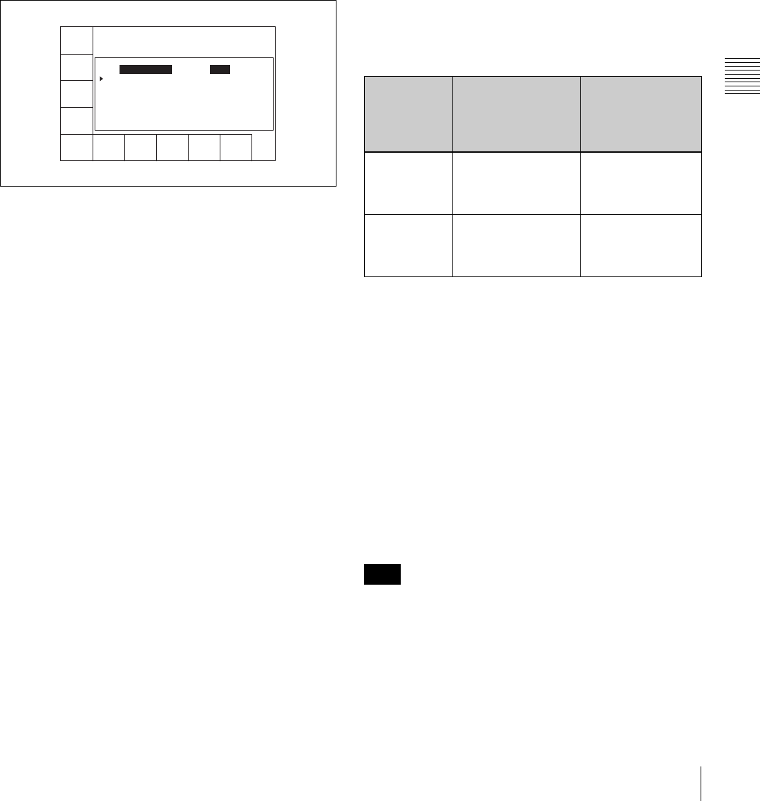
81
4-4 CUE Menu
Chapter 4 Menu Settings
To move the cursor using the numeric buttons
Enter the line number using the numeric buttons. Then
press the [F9] (CUENUM POINT) button. The cursor
will move to the line specified by the numeric buttons.
2
Use the numeric buttons to enter the time data in the
data entry window, and then press the SET button.
For example, to enter 00:01:30:00, press the numeric
buttons as follows: 0, 0, 1, 3, 0, 0, 0. (There is no need
to enter the first zero. When you enter a number that is
less than eight digits long, the unspecified digits are
automatically set to zero when the SET button is
pressed.)
3
Press the IN button (to enter IN point data) or OUT
button (to enter OUT point data).
The number is entered or it replaces the existing IN/
OUT point data.
To clear the IN/OUT point data
Use the cursor buttons to move the cursor to the IN/OUT
section to be cleared, and then press the CLR button while
holding down the IN button (to clear IN point data) or
OUT button (to clear OUT point data), or press the IN or
OUT button (to clear both IN and OUT point data) while
holding down the CLR button.
To increase or decrease IN/OUT point data one
frame at a time
Use the cursor buttons to move the cursor to the IN/OUT
section to be increased or decreased, and then press the +
button (to increase the time data) or the – button (to
decrease the time data) while holding down the IN button
or the OUT button. Each time you press the + or – button,
the time data is increased or decreased by one frame,
respectively.
To recall IN/OUT point data to the data entry
window
Use the cursor buttons to move the cursor to the IN/OUT
section to be recalled, and then press the RCL button while
holding down the IN button (to recall IN point data) or the
OUT button (to recall OUT point data).
To enter the current time code continuously
1
Set the VTR SETUP menu item 127 “Tele-File IN
OUT Input Continue” to “on”.
2
Use the cursor buttons to move the cursor to the IN/
OUT section to be entered.
To move the cursor using the numeric buttons
Enter the line number using the numeric buttons. Then
press the [F9] (CUENUM POINT) button. The cursor
will move to the line specified by the numeric buttons.
3
Press the IN button or OUT button while holding down
down the ENTRY button.
The movement of the cursor is automatic (as described
in the following table) and data is entered
continuously.
To display the duration between an IN point and
an OUT point
Use the cursor buttons to move the cursor to the IN/OUT
section and press the IN button and OUT button at the
same time. The duration between two points appears while
the buttons are pressed.
To preroll to an IN/OUT point
Use the cursor buttons to move the cursor to the IN/OUT
section and press the IN button (to preroll to an IN point)
or OUT button (to preroll to an OUT point) while holding
down the PREROLL button. The VTR prerolls to the point
and stops.
For details on setting the preroll time, see “4-2-6 Setting
the Preroll Time (PREROLL TIME)” on page 52.
If the cursor is not on the IN/OUT section when pressing
the IN/OUT button while pressing the PREROLL button,
the VTR prerolls to the cue point. When pressing the
PREROLL button only, the VTR prerolls to the cue point
regardless of the cursor position.
CUE
SCAN
ENTRY
POINT
INOUT
COMMNT
EDIT
CHANGE
DATA
DEL
POINT
PRO-
TECT
TAPE
INFO
CUENUM
POINT
WRITE/
EXIT
MARK
REC DATE[2003/05/14] EOS[00:00:12:08]
TITLE[ ] Rest100%
No. Out Tk Cut Scn
0 00:14:17:02 9 AAA
1 --:--:--:-- Input
condition
When the IN button
you press while
holding down the
ENTRY button
When the OUT
button you press
while holding
down the ENTRY
button
Only IN point
data has been
entered
IN point data is
modified and the
cursor stays on the IN
point data.
OUT point data is
entered and the
cursor moves to the
next IN point.
Only OUT
point data has
been entered
IN point data is
entered and the
cursor moves to the
next IN point.
OUT point data is
modified and the
cursor stays on the
OUT point.
Note
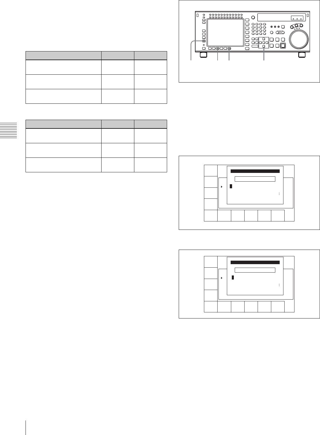
82 4-4 CUE Menu
Chapter 4 Menu Settings
Automatic time data changes during IN/OUT
point data entry or modification
The table below shows the automatic changes that occur in
time data when either the IN point or OUT point is
changed.
When IN point data is entered or modified:
When OUT point data is entered or modified:
Changing Tk data
Use the cursor buttons to move the cursor to the take data
to be changed. Then use the numeric buttons to change the
value. Note that values from 0 to 255 can be entered. Or,
move the cursor to the take data, and press the [F4]
(CHANGE DATA) button or the + button repeatedly to
increase the value in increments of 1. Press the – button
repeatedly to decrease the value in increments of 1. Note
that the value cannot go below 0.
Copying data
Use the cursor buttons to move the cursor to the destination
Mrk or Tk data, and press the RCL button. The Tk data
from the line above is copied to the selected line.
Changing Cut data
Use the cursor buttons to move the cursor to the cut data to
be changed, and then enter the new data using the numeric
buttons and +/– buttons. Pressing the – button enters the
tilde (~). Press the numeric buttons while pressing down
the SFT button to enter uppercase letters (A to J). Note that
a maximum of four characters can be entered.
Or, do the procedure below to change the data.
1
Press the cursor buttons to move the cursor to the cut
data to be changed.
To move the cursor using the numeric buttons
Enter the line number using the numeric buttons. Then
press the [F9] (CUENUM POINT) button. The cursor
will move to the line specified by the numeric buttons.
2
Press the [F4] (CHANGE DATA) button.
3
Press the T or t button to select a character.
4
Press the [F7] (SET LETTER) button or the cursor
center button.
The selected character is entered.
Status of input data IN point OUT point
The time sequence of the IN/
OUT point data is correct.
The data is
changed.
The data is
unchanged.
The time sequence of the IN/
OUT point data is not correct.
The data is
changed.
The data is
deleted.
The OUT point has not been
input.
The data is
changed.
The data is
unchanged.
Status of the input data IN point OUT point
The time sequence of the IN/
OUT point data is correct.
The data is
unchanged.
The data is
changed.
The time sequence of the IN/
OUT point data is not correct.
The data is
unchanged.
The data is
unchanged.
The IN point has not been
input.
The data is
unchanged.
The data is
changed.
1,3
246
SPACE SET
LETTER
CANCEL SAVE/
EXIT
BACK
SPACE
REC DATE[2003/02/25]
TITLE[ isplay Sample
No. Tape Format Duration
0 59i 1080 422 01:00:36:06 ---
1 59i 1080 422 01:00:36:06 ---
EOS[01:01:02:08]
] Rest100%
_
ABCDEFGHIJKLMNOPQRSTUVWXYZ
abcdefghjiklmnopqrstuvwxyz
0123456789[]()<>@+-*=!?:;
CUT No. EDIT
$#%&,."\^_'/~ {} HD1D2CAM
'
SPACE SET
LETTER
SAVE/
EXIT
BACK
SPACE
REC DATE[2003/02/25]
TITLE[ isplay Sample
No. Tape Format Duration
0 59i 1080 422 01:00:36:06 ---
1 59i 1080 422 01:00:36:06 ---
EOS[01:01:02:08]
] Rest100%
_
ABCDEFGHIJKLMNOPQRSTUVWXYZ
abcdefghjiklmnopqrstuvwxyz
0123456789[]()<>@+-*=!?:;
CUT No. EDIT
$#%&,."\^_'/~ {} HD1D2CAM
'
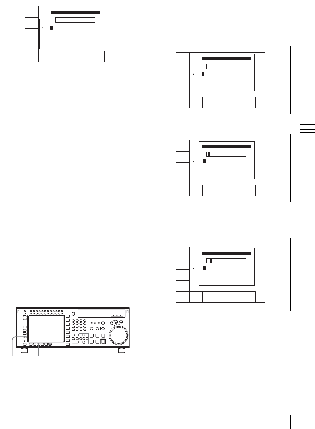
83
4-4 CUE Menu
Chapter 4 Menu Settings
5
Repeat steps 3 and 4 to enter more characters.
To enter a space
Press the [F5] (SPACE) button.
If you enter a wrong character
Press the [F6] (BACK SPACE) button to go back.
Then re-enter the character.
To start the procedure over again
Press the [F9] (CANCEL) button to start again.
To change a character
Press the cursor R button to move the cursor to the cut
data to be changed. Then press the cursor T or t
button to move the insertion position.
6
Press the [F10] (SAVE/EXIT) button.
The screen that was on before the cut data was changed
is displayed again.
To copy Cut data
Move the cursor to the line to which the copied data is to
be pasted. Then press the RCL button. The cut data from
the line above is copied to the selected line.
Changing scene data
Use the cursor buttons to move the cursor to the scene data
to be changed. Then enter the characters using the numeric
buttons and +/– buttons. Press the numeric buttons while
pressing down the SFT button to enter uppercase letters (A
to J). A maximum of three characters can be entered.
Or, do the procedure below to change the data.
1
Press the cursor buttons to move the cursor to the scene
data to be changed.
To move the cursor using the numeric buttons
Enter the line number using the numeric buttons. Then
press the [F9] (CUENUM POINT) button. The cursor
will move to the line specified by the numeric buttons.
2
Press the [F4] (CHANGE DATA) button.
3
Press the cursor T or t button to select a character.
4
Press the [F7] (SET LETTER) button or the cursor
center button.
The selected character is entered.
5
Repeat steps 3 and 4 to enter more characters.
To enter a space
Press the [F5] (SPACE) button.
If you enter a wrong character
Press the [F6] (BACK SPACE) button to go back.
Then re-enter the character.
To start the procedure over again
Press the [F9] (CANCEL) button to start again.
SPACE SET
LETTER
CANCEL SAVE/
EXIT
BACK
SPACE
REC DATE[2003/02/25]
TITLE[ isplay Sample
No. Tape Format Duration
0 59i 1080 422 01:00:36:06 --
1 59i 1080 422 01:00:36:06 ---
EOS[01:01:02:08]
] Rest100%
AAA_
ABCDEFGHIJKLMNOPQRSTUVWXYZ
abcdefghjiklmnopqrstuvwxyz
0123456789[]()<>@+-*=!?:;
CUT No. EDIT
$#%&,."\^_'/~ {} HD1D2CAM
'
1,346
2
SPACE SET
LETTER
CANCEL SAVE/
EXIT
BACK
SPACE
REC DATE[2003/02/25]
TITLE[ isplay Sample
No. Tape Format Duration
0 59i 1080 422 01:00:36:06 --
1 59i 1080 422 01:00:36:06 ---
EOS[01:01:02:08]
] Rest100%
_
ABCDEFGHIJKLMNOPQRSTUVWXYZ
abcdefghjiklmnopqrstuvwxyz
0123456789[]()<>@+-*=!?:;
SCENE No. EDIT
$#%&,."\^_'/~ {} HD1D2CAM
'
SPACE SET
LETTER
SAVE/
EXIT
BACK
SPACE
REC DATE[2003/02/25]
TITLE[ isplay Sample
No. Tape Format Duration
0 59i 1080 422 01:00:36:06 --
1 59i 1080 422 01:00:36:06 ---
EOS[01:01:02:08]
] Rest100%
B
ABCDEFGHIJKLMNOPQRSTUVWXYZ
abcdefghjiklmnopqrstuvwxyz
0123456789[]()<>@+-*=!?:;
SCENE No. EDIT
$#%&,."\^_'/~ {} HD1D2CAM
'
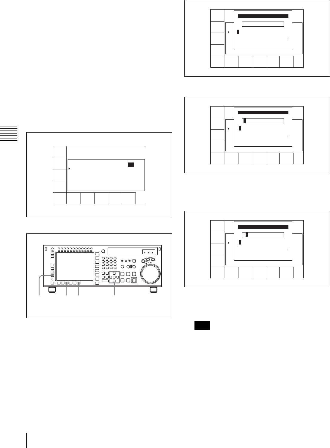
84 4-4 CUE Menu
Chapter 4 Menu Settings
To change a character
Press the cursor R button to move the cursor to the
scene data to be changed. Then press the cursor T or
t button to move the insertion position.
6
Press the [F10] (SAVE/EXIT) button.
The screen that was on before the scene data was
entered is displayed again.
To copy Scn data
Move the cursor to the line to which the copied data is to
be pasted. Then press the RCL button.
The scene data from the line above is copied to the selected
line.
Changing Comment data
To display comment data, press the t button several
times.
To change Comment data
1
Press the cursor buttons to move the cursor to the
comment to be changed.
To move the cursor using the numeric buttons
Enter the line number using the numeric buttons. Then
press the [F9] (CUENUM POINT) button. The cursor
will move to the line specified by the numeric buttons.
2
Press the [F3] (COMMNT EDIT) button.
3
Press the cursor T or t button to select a character.
4
Press the [F7] (SET LETTER) button or the cursor
center button.
The selected character is entered.
5
Repeat steps 3 and 4 to enter more characters.
Up to 80 characters can be entered.
If excessive comment data are entered, the input of cue
point data may become disabled. To prevent this, press
the [F8] (TAPE INFO) button to check the available
memory.
To enter a space
Press the [F5] (SPACE) button.
If you enter a wrong character
Press the [F6] (BACK SPACE) button to go back.
Then re-enter the character.
CUE
SCAN
ENTRY
POINT
INOUT
COMMNT
EDIT
CHANGE
DATA
DEL
POINT
PRO-
TECT
TAPE
INFO
CUENUM
POINT
WRITE/
EXIT
MARK
REC DATE[2003/02/25] EOS[01:01:24:15]
TITLE[ ] Rast100%
No. Out Tk Cut Scn
0 00:14:17:02 9 AAA 111
1 --:--:--:--
1,346
2
Note
SPACE SET
LETTER
CANCEL SAVE/
EXIT
BACK
SPACE
REC DATE[2003/02/25]
TITLE[ isplay Sample
No. Tape Format Duration
0 59i 1080 422 01:00:36:06 --
1 59i 1080 422 01:00:36:06 ---
EOS[01:01:02:08]
] Rest100%
_
ABCDEFGHIJKLMNOPQRSTUVWXYZ
abcdefghjiklmnopqrstuvwxyz
0123456789[]()<>@+-*=!?:;
COMMENT EDIT
$#%&,."\^_'/~ {} HD1D2CAM
'
SPACE SET
LETTER
CANCEL SAVE/
EXIT
BACK
SPACE
REC DATE[2003/02/25]
TITLE[ isplay Sample
No. Tape Format Duration
0 59i 1080 422 01:00:36:06 --
1 59i 1080 422 01:00:36:06 ---
EOS[01:01:02:08]
] Rest100%
abcdefghjiklmnopqrstuvwxyz
0123456789[]()<>@+-*=!?:;
COMMENT EDIT
$#%&,."\^_'/~ {} HD1D2CAM
'
ABCDEFGHIJKLMNOPQRSTUVWXYZ
B
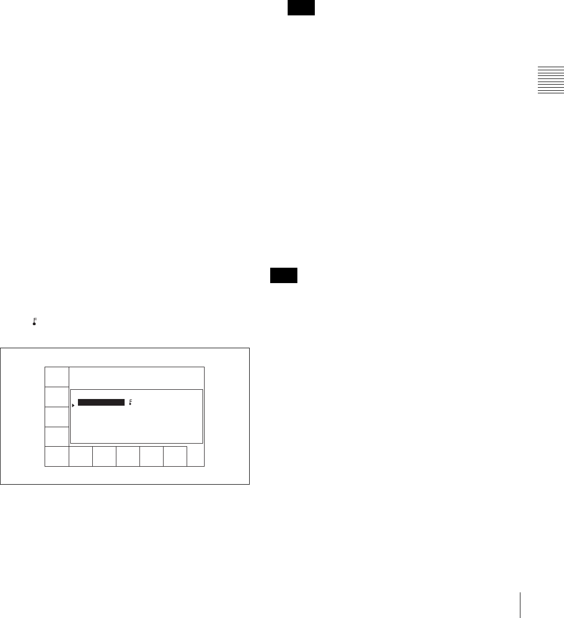
85
4-4 CUE Menu
Chapter 4 Menu Settings
To start the procedure over again
Press the [F9] (CANCEL) button to start again.
To change a character
Press the cursor R button to move the cursor to the
comment to be changed. Then press the cursor T or
t button to move the insertion position.
If the entered text is longer than the comment box
t or T appears to the left or right of the box.
6
Press the [F10] (SAVE/EXIT) button.
The screen that was on before the comment data was
changed is displayed again.
Prerolling to a cue point
1
Press the [F1] (CUE SCAN) button repeatedly to
specify the direction in which the cursor moves when
the PREROLL button is pressed.
Each press of the button changes the direction as
follows: FWD (forward) t REW (reverse) t
unspecified.
FWD: Pressing the PREROLL button causes the
cursor to move to the next line, and the VTR to
preroll to the time code on that line. Invalid time
codes are ignored.
REW: Pressing the PREROLL button causes the
cursor to move to the previous line, and the VTR
to preroll to the time code on that line. Invalid
time codes are ignored.
2
Press the PREROLL button.
Write-protecting cue point data
Press the cursor buttons to move the cursor to the line that
is to be write-protected. Then press the [F7] (PROTECT)
button. appears between the Time and Mrk columns to
indicate that the line (clip) is write-protected.
To cancel a write-protection
Press the [F7] (PROTECT) button. A message appears (in
the control panel display) requesting confirmation of
cancellation operation.
Press the [F7] (PROTECT) button while holding down the
SFT button.
Inserting a new line
1
Use the cursor buttons to move the cursor to the line
that will be under the new line to be inserted.
To move the cursor using the numeric buttons
Enter the line number using the numeric buttons. Then
press the [F9] (CUENUM POINT) button. The cursor
will move to the line specified by the numeric buttons.
If the movement of the cursor (B) is not linked with
the cursor buttons, the cursor (B) will not move when
the cursor buttons are pressed.
To link the cursor (B) with the cursor buttons
Press the cursor center button. Each press of the button
alternately links and unlinks the cursor (B).
2
Press the ENTRY button while holding down the SFT
button.
A new line is inserted above the line where the
cursor (B) is located, and the current time data is
entered on the new line.
Moving a line
Press the cursor buttons to move the cursor to the Time
data of the line to be moved. Then press the + or – button.
Each press of the + button moves the line up, while each
press of the – button moves the line down.
If you perform the procedure above while the cursor is on
any other data other than the Time data, only the contents
selected by the cursor will be moved. To move the entire
line, be sure that the cursor is placed on the Time data.
Deleting a line
Press the cursor button to move the cursor to the line to be
deleted, and then press the [F5] (DEL POINT) button
while pressing down the SFT button. The line is deleted
and all the line numbers below are decreased by one.
Displaying other information saved to the
MLB-1M-100 memory label
Press the [F8] (TAPE INFO) button. The TAPE
INFORMATION window appears, showing other
information.
CUE
SCAN
ENTRY
POINT
COMMNT
EDIT
CHANGE
DATA
DEL
POINT
PRO-
TECT
TAPE
INFO
CUENUM
POINT
WRITE/
EXIT
MARK
REC DATE[2003/02/25] EOS[01:01:24:15]
TITLE[ ] Rast100%
No. Time Mrk Tk Cut Scn
0 00:01:02:03 NG 00:01:01:03
1 --:--:--:-- KP --:--:--:--
2 00:03:04:03 OK @ 00:03:03:03
3 00:04:04:03 OK 00:04:03:03
4 00:05:05:03 NG 00:05:04:03
5 00:06:06:03 OK 00:06:05:03
6 --:--:--:--
Note
Note
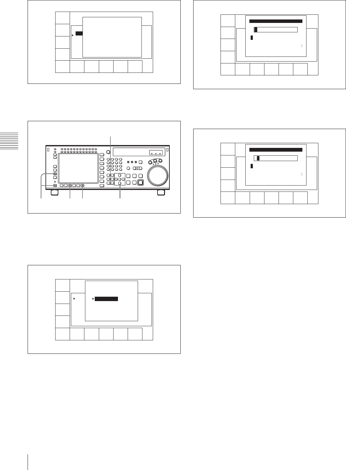
86 4-4 CUE Menu
Chapter 4 Menu Settings
To close the window
Press the [F8] (TAPE INFO) button again.
To change ID or ADMIN data
1
Press the ALT/[F3] (ATTRIB EDIT) buttons.
2
Press the R or r button to select “ID” (tape ID) or
“ADMIN” (administrator), then press the ENTRY
button.
3
Press the T or t button to select a character.
4
Press the[F7] (SET LETTER) button or the cursor
center button.
The selected character is entered.
5
Repeat steps 3 and 4 to enter more characters.
To enter a space
Press the [F5] (SPACE) button.
If you enter a wrong character
Press the [F6] (BACK SPACE) button to go back.
Then re-enter the character.
To start the procedure over again
Press the [F9] (CANCEL) button to start again.
To change a character
Press the cursor R button to move the cursor to the ID
or ADMIN box. Then press the cursor T or t button
to move the insertion position.
If entered text is longer than the ID or ADMIN box
t or T appears to the left or right of the box.
6
Press the [F10] (SAVE/EXIT) button.
The screen that was on before the ID or ADMIN data
was changed is displayed again.
CUE
SCAN
ENTRY
POINT
COMMNT
EDIT
CHANGE
DATA
DEL
POINT
PRO-
TECT
TAPE
INFO
CUENUM
POINT
WRITE/
EXIT
MARK
REC DATE[2003/02/25] EOS[01:01:24:15]
TITLE[ ] Rest100%
No. Time Mrk Tk Cut Scn
0 00:01:02:03 NG 00:01:01:03
1 --:--:--:-- KP --:--:--:--
2 00:03:04:03 OK @ 00:03:03:03
3 00:04:04:03 OK 00:04:03:03
4 00:05:05:03 NG 00:05:04:03
5 00:06:06:03 OK 00:06:05:03
6 --:--:--:--
TAPE INFORMATION
ID: 001234567 TITLE
ADMIN: Kanrisha
MODEL: HDW-700
SERIAL NUMBER:000123
WRITE PROTECT: ON
TAPE THREAD COUNT: 123
CUE POINT NUMBER: 5
CONTROL MODE: panel
SIZE: 1024 USED: 234
2,3,446
2
1
FORMAT
T-Fil
UNDO
ALL
ATTAI
EDIT
COPY
toCUE
T-Fil
MODE
WRITE
PRTEC
REC DATE[2003/02/25]
TITLE[NAplay Sample
No. Time Mrk Tk Cut Scn
0 00:01:02:03 NG 01 0015 A01
1 00:02:03:03 KP 02 0015 A01
2 00:03:04:03 OK @ 03 0015 A01
3 00:04:05:03 OK 01 017~ A01
4 00:05:06:03 NG 01 B20
5 00:06:07:03 OK 02 B20
6 --:--:--:--
EOS[01:01:--:--]
] Rest 50%
ATTRIB EDIT SELECT
TITLE
ID
ADMIN
Press [ENTRY] to edit
Press [CLR] to CANCEL
SPACE SET
LETTER
SAVE/
EXIT
BACK
SPACE
ABCDEFGHIJKLMNOPQRSTUVWXYZ
abcdefghjiklmnopqrstuvwxyz
0123456789[]()<>@+-*=!?:;
Id Edit
$#%&,."\^_'/~ {} HD1D2CAM
'
SPACE SET
LETTER
CANCEL SAVE/
EXIT
BACK
SPACE
B
ABCDEFGHIJKLMNOPQRSTUVWXYZ
abcdefghjiklmnopqrstuvwxyz
0123456789[]()<>@+-*=!?:;
Id Edit
$#%&,."\^_'/~ {} HD1D2CAM
'
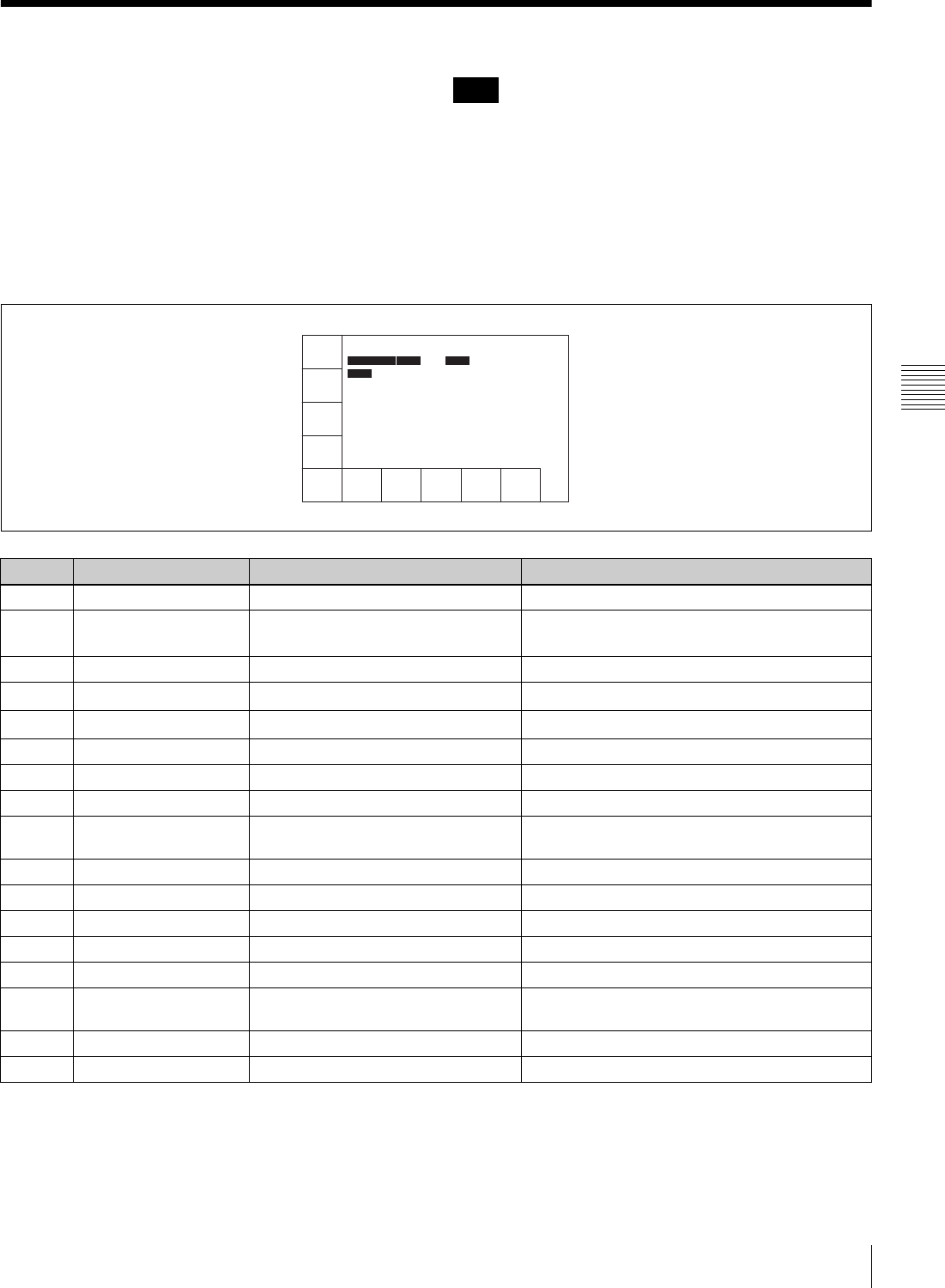
87
4-5 VIDEO Menu
Chapter 4 Menu Settings
4-5 VIDEO Menu
In the VIDEO menu, adjust the video signal. The VIDEO
menu screen shows the VTR operation mode, current
position time code, time code type, and so on.
About HD image quality adjustments
When playing back tapes recorded in Y/PB/PR (4:2:2)
format, HD image quality adjustments are enabled for the
HD SDI OUTPUT 1, 2, and MONITOR connectors.
HD image quality adjustments are not possible when
playing back tapes recorded in GBR (4:4:4) format. Also,
HD image quality adjustments are not possible when the
optional HKSR-5001 Format Converter Board is installed
and Y/PB/PR (4:2:2) format signals are output from the
FORMAT CONV. OUT (OPTION) 1 and 2 connectors.
To access the VIDEO menu screen
Press the VIDEO button.
Note
Button Indication Function Settings
[F2] SERVO REF Selects the reference signal for output. ext, input, auto
[F4] MASTER (HD) Adjusts the Y, PB, and PR output levels
simultaneously.
prst, 0.0 to 141.3%
[F5] Y (HD) Adjusts the Y output level. prst, 0.0 to 141.3%
[F6] PB (HD) Adjusts the PB output level. prst, 0.0 to 141.3%
[F7] PR (HD) Adjusts the PR output level. prst, 0.0 to 141.3%
[F8] SETUP (HD) Adjusts the setup level. prst, –10.0 to +10.0
[F9] SYNC (HD) Adjusts the sync phase. prst, –128 to +127
[F10] FINE (HD) Fine adjustment of the sync phase. prst, 0 to 1024
ALT/[F1] MASTER LEVEL (D1) Adjusts the Y, B-Y, and R-Y output
levels simultaneously.
prst, 0.0 to 141.3%
ALT/[F2] Y LEVEL (D1) Adjusts the Y output level. prst, 0.0 to 141.3%
ALT/[F3] B-Y LEVEL (D1) Adjusts the B-Y output level. prst, 0.0 to 141.3%
ALT/[F4] R-Y LEVEL (D1) Adjusts the R-Y output level. prst, 0.0 to 141.3%
ALT/[F5] VIDEO GAIN (ALL) Adjusts the video gain. prst, 0.0 to 141.3%
ALT/[F6] CHROMA GAIN (ALL) Adjusts the chroma gain. prst, 0.0 to 141.3%
ALT/[F7] CHROMA PHASE
(ALL)
Adjusts the chroma phase. prst, –127 to +127
ALT/[F8] BLACK LEVEL (ALL) Adjusts the black level. prst, –31.0 to +31.0%
ALT/[F9] SETUP LEVEL (CST) Adjusts the setup level. prst, 0 to +10.0
LTC
TCR
INTRP DF F2
SERVO
REF
MASTER
(HD)
Y
(HD)
PR
(HD)
SETUP
(HD)
SYNC
(HD)
FINE
(HD)
PB
(HD)
00H00M00S00F
AIN --:--:--:-- AOUT --:--:--:--
IN --:--:--:-- OUT --:--:--:--
TAPE LOCK

88 4-5 VIDEO Menu
Chapter 4 Menu Settings
4-5-1 Selecting the Reference
Signal (SERVO REF)
Press the [F2] (SERVO REF) button to select the signal to
be used as the reference signal for VTR operations.
ext: The servo reference signal is forced to be EXT.
input: The signal from the HD SDI INPUT A/B connector
is used as the reference signal for VTR operations.
The [F1] (VIDEO IN) button switches the video input
signal.
auto: During recording or edit preset, the signal from the
HD SDI INPUT A/B connector is used as a reference
signal. In all other cases, the servo operates using the
signal setting of the VTR SETUP menu item 006
“EXTERNAL REFERENCE select”. If the signal
selected in the menu item 006 “EXTERNAL
REFERENCE select” is not present, the servo
operates using an internal reference.
4-5-2 Adjusting the Output Video
Signal (MASTER to FINE)
Adjusting the output video signal
Set the output video signal menu items as follows.
1
Press the function selection button ([F4], for example).
The setting display lights up.
2
With the R and r buttons (or MULTI CONTROL
knob), change the numeric value.
Setting to the preset values
Press the cursor center button or MULTI CONTROL
knob.
The prst (preset) indication appears.
3
At the desired setting value, press the function
selection button ([F4], for example).
The numeric values change as follows.
[F4] button MASTER (HD): Pressing this button makes
it active, and the cursor R and r buttons increase or
decrease the value by 0.1. You can also change the
setting with the MULTI CONTROL knob.
[F5] button Y (HD): Pressing this button makes it active,
and the cursor R and r buttons increase or decrease the
value by 0.1. You can also change the setting with the
MULTI CONTROL knob.
[F6] button PB (HD): Pressing this button makes it active,
and the cursor R and r buttons increase or decrease the
value by 0.1. You can also change the setting with the
MULTI CONTROL knob.
[F7] button PR (HD): Pressing this button makes it active,
and the cursor R and r buttons increase or decrease the
value by 0.1. You can also change the setting with the
MULTI CONTROL knob.
[F8] button SETUP (HD): Pressing this button makes it
active, and the cursor R and r buttons increase or
decrease the value by 0.5. You can also change the
setting with the MULTI CONTROL knob.
[F9] button SYNC (HD): Pressing this button makes it
active, and the cursor R and r buttons increase or
decrease the value by 1. You can also change the
setting with the MULTI CONTROL knob.
[F10] button FINE (HD): Pressing this button makes it
active, and the cursor R and r buttons increase or
decrease the value by 1. You can also change the
setting with the MULTI CONTROL knob.
ALT/[F1] button MASTER: Pressing this button makes
it active, and the cursor R and r buttons increase or
decrease the value by 0.1. You can also change the
setting with the MULTI CONTROL knob.
ALT/[F2] button Y (D1): Pressing this button makes it
active, and the cursor R and r buttons increase or
decrease the value by 0.1. You can also change the
setting with the MULTI CONTROL knob.
ALT/[F3] button B-Y (D1): Pressing this button makes it
active, and the cursor R and r buttons increase or
decrease the value by 0.1. You can also change the
setting with the MULTI CONTROL knob.
ALT/[F4] button R-Y (D1): Pressing this button makes it
active, and the cursor R and r buttons increase or
decrease the value by 0.1. You can also change the
setting with the MULTI CONTROL knob.
ALT/[F5] button V GAIN (ALL): Pressing this button
makes it active, and the cursor R and r buttons
increase or decrease the value by 0.1. You can also
change the setting with the MULTI CONTROL knob.
ALT/[F6] button CRM GA (ALL): Pressing this button
makes it active, and the cursor R and r buttons
increase or decrease the value by 0.1. You can also
change the setting with the MULTI CONTROL knob.
ALT/[F7] button CRM PH (ALL): Pressing this button
makes it active, and the cursor R and r buttons
increase or decrease the value by 1. You can also
change the setting with the MULTI CONTROL knob.
1,3 2

89
4-5 VIDEO Menu
Chapter 4 Menu Settings
ALT/[F8] button BLK LV (ALL): Pressing this button
makes it active, and the cursor R and r buttons
increase or decrease the value by 1. You can also
change the setting with the MULTI CONTROL knob.
ALT/[F9] button SETUP (CST): Pressing this button
makes it active, and the cursor R and r buttons
increase or decrease the value by 0.1. You can also
change the setting with the MULTI CONTROL knob.
Adjusting the master output level (HD)
Make this adjustment with the [F4] (MASTER LEVEL)
button.
prst: 100% (4000H)
Numerical value: 0.0 (0H) to 141.3% (5A70H)
Adjustable range: –∞ to +3 dB
This setting can also be carried out in the VTR SETUP
menu item 708 “MASTER LEVEL (HD)”.
Adjusting the Y output level (HD)
Make this adjustment with the [F5] (Y (HD)) button.
prst: 100% (4000H)
Numerical value: 0.0 (0H) to 141.3% (5A70H)
Adjustable range: –∞ to +3 dB
This setting can also be carried out in the VTR SETUP
menu item 709 “Y LEVEL (HD)”.
Adjusting the PB output level (HD)
Make this adjustment with the [F6] (PB (HD)) button.
prst: 100% (4000H)
Numerical value: 0.0 (0H) to 141.3% (5A70H)
Adjustable range: –∞ to +3 dB
This setting can also be carried out in the VTR SETUP
menu item 710 “PB LEVEL (HD)”.
Adjusting the PR output level (HD)
Make this adjustment with the [F7] (PR LEVEL) button.
prst: 100% (4000H)
Numerical value: 0.0 (0H) to 141.3% (5A70H)
Adjustable range: –∞ to +3 dB
This setting can also be carried out in the VTR SETUP
menu item 711 “PR LEVEL (HD)”.
Adjusting the setup level (HD)
Make this adjustment with the [F8] (SETUP LEVEL)
button.
prst: 0% (0)
Numerical value: –10.0 to +10.0
Adjustable range: –10 to +10%
This setting can also be carried out in the VTR SETUP
menu item 712 “SETUP LEVEL (HD)”.
Adjusting the sync phase (HD)
Use this setting to precisely match the output phase of the
VTR to the reference signal or when using a switcher or
other device connected to another VTR to create special
effects such as fading, wrapping, and dissolving.
To adjust the output signal sync phase with respect to the
reference input, make this adjustment with the [F9] (SYNC
PHASE) button.
prst: 0 (0)
Numerical value: –128 to +127
Adjustable range: –1.4 to +1.4H
This setting can also be carried out in the VTR SETUP
menu item 713 “SYNC PHASE (HD)”.
Fine adjustment of the sync phase (HD)
Make this adjustment with the [F10] (FINE) button.
prst: 0 (0)
Numerical value: 0 to 1024
Adjustable range: 0 to 323 nsec
This setting can also be carried out in the VTR SETUP
menu item 714 “FINE (HD)”.
Adjusting the master output level (D1)
Make this adjustment with the ALT/[F1] (MASTER
LEVEL) buttons.
prst: 100% (4000H)
Numerical value: 0.0 (0H) to 141.3%
Adjustable range: –∞ to +3 dB
This setting can also be carried out in the VTR SETUP
menu item 755 “MASTER LEVEL (D1)”.
Adjusting the Y output level (D1)
Make this adjustment with the ALT/[F2] (Y LEVEL)
buttons.
prst: 100% (4000H)
Numerical value: 0.0 (0H) to 141.3% (5A70H)
Adjustable range: –∞ to +3 dB
This setting can also be carried out in the VTR SETUP
menu item 756 “Y LEVEL (D1)”.
Adjusting the R–Y output level (D1)
Make this adjustment with the ALT/[F4] (R–Y LEVEL)
buttons.
prst: 100% (4000H)
Numerical value: 0.0 (0H) to 141.3% (5A70H)
Adjustable range: –∞ to +3 dB
This setting can also be carried out in the VTR SETUP
menu item 758 “R-Y LEVEL (D1)”.
Adjusting the video gain output level (HD/
SD)
Make this adjustment with the ALT/[F5] (V GAIN (ALL))
buttons.

90 4-5 VIDEO Menu
Chapter 4 Menu Settings
prst: 100% (4000H)
Numerical value: 0.0 (0H) to 141.3% (5A70H)
Adjustable range: 0.0% to 141.3%
This setting can also be carried out in the VTR SETUP
menu item 740 “VIDEO GAIN (ALL)”.
Adjusting the chroma gain output level
(HD/SD)
Make this adjustment with the ALT/[F6] (CRM GA
(ALL)) buttons.
prst: 100% (4000H)
Numerical value: 0.0 (0H) to 141.3% (5A70H)
Adjustable range: 0.0% to 141.3%
This setting can also be carried out in the VTR SETUP
menu item 741 “CHROMA GAIN (ALL)”.
Adjusting the chroma phase output level
(HD/SD)
Make this adjustment with the ALT/[F7] (CRM PH
(ALL)) buttons.
prst: 0
Numerical value: –127 to +127
Adjustable range: –30º to +30º
This setting can also be carried out in the VTR SETUP
menu item 742 “CHROMA PHASE (ALL)”.
Adjusting the black output level (HD/SD)
Make this adjustment with the ALT/[F8] (BLK LV (ALL))
buttons.
prst: 0.0% (110H)
Numerical value: –31.0% (0H) to +31.0% (220H)
Adjustable range: –31.0% to +31.0%
This setting can also be carried out in the VTR SETUP
menu item 743 “BLACK LEVEL (ALL)”.
Adjusting the setup level (COMPOSITE)
Make this adjustment with the ALT/[F9] (SETUP LEVEL)
buttons.
prst: 7.5 IRE
Numerical value: 0 to +10.0
Adjustable range: 0 to +10.0 IRE
This setting can also be carried out in the VTR SETUP
menu item 762 “SETUP LEVEL (CST)”.
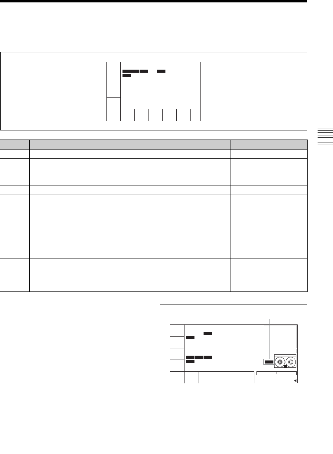
91
4-6 AUDIO Menu
Chapter 4 Menu Settings
4-6 AUDIO Menu
In the AUDIO menu, make audio signal adjustments. The
AUDIO menu screen shows the VTR operation mode,
current position time code, time code type, and so on.
To access the AUDIO menu screen
Press the AUDIO button.
Display when audio output channel
settings do not match track number
settings
• As shown below, “EXCHNG” is displayed if even one
of the HD SDI, AES/EBU, ANALOG, SD SDI output
channels does not match the corresponding track
number.
•The
[F3] button in the AUDIO menu is highlighted in
orange if even one of the HD SDI, AES/EBU audio
output channels does not match the corresponding track
AUDIO
IN
-
DIGOUT
EXCHNG
-
ANAOUT
EXCHNG
-
SDOUT
EXCHNG
-
00 01M56S27F
AIN --:--:--:-- AOUT --:--:--:--
IN --:--:--:-- OUT --:--:--:--
INTRP DF F2
LTC
TCR
TAPE LOCK
Button Indication Function Settings
[F1] AUDIO IN Accesses the AUDIO INPUT menu SDI, AES/EBU
[F3] DIGOUT EXCHNG Digital audio output signal source track selection
(HD SDI, SD SDI, AES/EBU)
However, [F5] (SDOUT EXCHNG) can be used to set
SD SDI source tracks independently.
TR1 to TR12
[F4] ANAOUT EXCHNG Analog audio output signal source track selection TR1 to TR12
[F5] SDOUT EXCHNG Digital audio output signal source track selection (SD
SDI)
dis, ena, TR1 to TR12
ALT/[F1] AUDIO EDIT Audio transition type selection for digital audio editing cross, fi/fo, cut
ALT/[F2] FADE TIME Fade time selection 5 ms to 115 ms
ALT/[F3] REPLACE MODE CH1 to CH8 assignment settings in response to an
external digital audio preset command
ALT/[F4] ANALOG REPLACE CH9 to CH12 assignment settings in response to an
external analog audio preset command
ALT/[F5] PITCH GROUP Sets the relation between audio channels when
performing pitch correction during program play or
play at a different frequency (23.98 frame y 24
frame, 23.98/24 frame y 25 frame, 29.97 frame y
30 frame).
PB/EE
EE
CTL
NDF
STANDBY OFF
RECINH
off
ASSEN-
BLE
off
INS
TC
off
INS
VIDEO
off
INS
CUE
off
INS
AUDIO
-
STILL HDCAM-SR
SS
REMAIN:--H--M
HOME
00
H
00
M
00
S
00
F
AIN --:--:--:-- AOUT --:--:--:--
IN --:--:--:-- OUT --:--:--:--
00
H
29
M
21
S
05
F
INTRP DF
EXCHNG
2FO
LTC
TCR
“EXCHNG” display
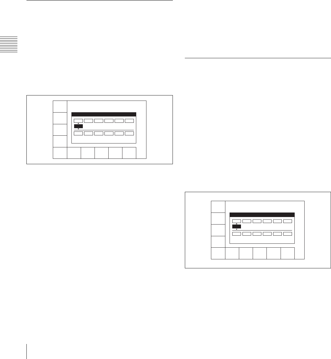
92 4-6 AUDIO Menu
Chapter 4 Menu Settings
number on the tape.
In this case, if SDOUT EXCHNG is set to “dis”, the [F5]
button is also highlighted in orange.
•The
[F4] button in the AUDIO menu is highlighted in
orange if even one of the ANALOG audio output
channels does not match the corresponding track number
on the tape.
•The
[F5] button in the AUDIO menu is highlighted in
orange if even one of the SD SDI audio output channels
does not match the corresponding track number on the
tape.
4-6-1 Selecting the Audio Input
Signal (AUDIO IN)
To select the audio input signal for CH1 to CH12, use the
following procedure.
CH1 to CH12 can be selected for HDCAM-SR, and CH1
to CH4 can be selected for HDCAM.
1
Press the [F1] (AUDIO IN) button.
The AUDIO INPUT menu appears, together with an
audio input selection window.
2
Select the audio input signal for each channel.
SDI: audio signal input from the HD SDI INPUT A/B
connector
AES/EBU: audio signal input from the DIGITAL I/O
(AES/EBU) INPUT connector
3
Press the [F10] (EXIT) button.
This returns to the AUDIO menu screen.
To make settings for individual channels with the
F buttons
By pressing any of the [F1] (A-IN CH1) to [F8] (A-IN
CH8) buttons in the AUDIO INPUT menu, and the [F1]
(A-IN CH9) to [F4] (A-IN CH12) buttons in the
ALT+AUDIO screen obtained by pressing the ALT
button, you can select the type of input signal for each
channel.
To make input signal selections for individual
channels with the numeric buttons
1
Press the cursor T or t button, to align the cursor
with the channel for which you want to make the
selection.
2
Press the cursor R or r button, to select the signal.
To return to the default settings
Press the cursor center button. The cursor item returns to
the default.
To select the same input signal simultaneously
on all twelve channels
Press the [F9] (A-IN ALL) button to change the input
signal simultaneously on all twelve channels.
You can also make this setting using the VTR SETUP
menu item 830 “AUDIO INPUT SELECT”.
4-6-2 Digital Audio Output Signal
Source Track Selection (DIGOUT
EXCHNG)
To make the source track selection for the digital audio
output signal (audio multiplexed with HD SDI and SD SDI
(1 to 8 channels), and AES/EBU audio output are targeted)
on each of channels 1 to 12, use the following procedure.
Note that when [F9] (SDOUT EXCHNG) in the SDOUT
menu is set to “ena”, SD SDI source track selection
follows the settings of the SDOUT menu.
1
Press the [F3] (DIGOUT EXCHNG) button.
The DIGOUT menu appears, together with a source
track selection window for the digital audio output
signals.
2
Carry out the source track selection for the digital
audio output signal on each channel.
TR1 to TR12: Select the audio signals recorded on
tracks 1 to 12.
3
Press the [F10] (EXIT) button.
A-IN
CH1
AES/EB
A-IN
CH2
AES/EB
A-IN
CH3
SDI
A-IN
CH4
SDI
A-IN
CH5
SDI
A-IN
CH7
SDI
A-IN
CH8
SDI
A-IN
ALL
.....
EXITA-IN
CH6
SDI
AUDIO INPUT SELECT
CH1
A/E
CH2
A/E
CH3
SDI
CH4
SDI
CH5
SDI
CH6
SDI
CH7
SDI
CH8
SDI
CH9
SDI
CH10
SDI
CH11
SDI
CH12
SDI
DIGOUT
CH1
TR1
DIGOUT
CH2
TR2
DIGOUT
CH3
TR3
DIGOUT
CH4
TR4
DIGOUT
CH5
TR5
DIGOUT
CH7
TR7
DIGOUT
CH8
TR8
EXITDIGOUT
CH6
TR6
AUDIO OUTPUT EXCHANGE
CH1
TR1
CH2
TR2
CH3
TR3
CH4
TR4
CH5
TR5
CH6
TR6
CH7
TR7
CH8
TR8
CH9
TR9
CH10
TR10
CH11
TR11
CH12
TR12
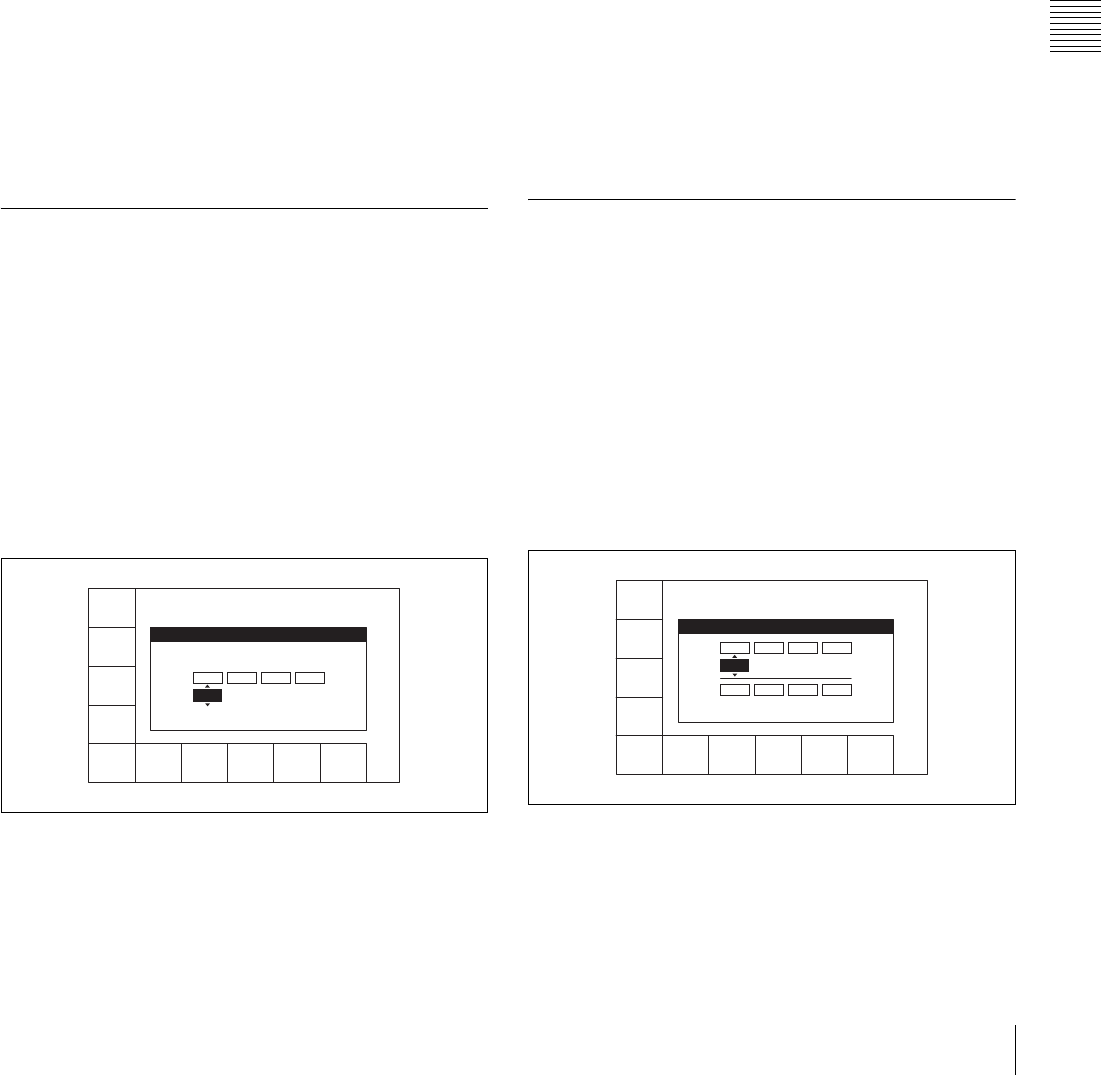
93
4-6 AUDIO Menu
Chapter 4 Menu Settings
This returns to the AUDIO menu screen.
To make output settings for individual channels
with the F buttons
By pressing any of the [F1] (DIGOUT CH1 TR1) to [F8]
(DIGOUT CH8 TR8) buttons menu, and the [F1]
(DIGOUT CH9) to [F4] (DIGOUT CH12) buttons in the
ALT+DIG OUT screen obtained by pressing the ALT
button, you can select the source track for each channel.
To make input signal selections for individual
channels with the numeric buttons
1
Press the cursor T or t button, to align the cursor
with the channel for which you want to make the
selection.
2
Press the cursor R or r button, to select the source track
to be output.
To return to the default settings
Press the cursor center button. The cursor item returns to
the default.
You can also make this setting using VTR SETUP menu
item 834 “DIGITAL AUDIO OUTPUT EXCHANGE”.
4-6-3 Analog Audio Output Signal
Source Track Selection (ANAOUT
EXCHNG)
To make the source track selection for the analog audio
output signal on each of CH1 to CH4, use the following
procedure.
1
Press the [F4] (ANAOUT EXCHNG) button.
The ANAOUT menu appears, together with a source
track selection window for the analog audio output
signals.
2
Carry out the source track selection for the analog
audio output signal on each channel.
TR1 to TR12: Select the audio signals recorded on
tracks 1 to 12.
3
Press the [F10] (EXIT) button.
This returns to the AUDIO menu screen.
To make output settings for individual channels
with the F buttons
By pressing any of the [F1] (ANAOUT CH1 TR1) to [F4]
(ANAOUT CH4 TR4) buttons, you can select the source
track for each channel.
To make input signal selections for individual
channels with the numeric buttons
1
Press the cursor T or t button, to align the cursor
with the channel for which you want to make the
selection.
2
Press the cursor R or r button, to select the source track
to be output.
To return to the default settings
Press the cursor center button. The cursor item returns to
the default.
You can also make this setting using VTR SETUP menu
item 835 “ANALOG AUDIO OUTPUT EXCHANGE”.
4-6-4 Digital Audio Output Signal
Source Track Selection (SDOUT
EXCHNG)
To make the source track selection for the digital audio
output signal (audio multiplexed with SD SDI), use the
following procedure.
1
Press the [F5] (SDOUT EXCHNG) button.
The SDOUT menu appears, together with a source
track selection menu for the digital audio output
signals.
2
Press [F9] (SD OUT EXCHNG) to set the display to
“ena”s.
ena: Enable the settings of this menu.
dis: Disable the settings of this menu, and use the
settings for CH1 to CH8 of DIGOUT EXCHNG.
ANAOUT
CH1
TR1
ANAOUT
CH2
TR2
ANAOUT
CH3
TR3
ANAOUT
CH4
TR4
EXIT
ANALOG AUDIO OUTPUT EXCHANGE
CH1
TR1
CH2
TR2
CH3
TR3
CH4
TR4
SD OUT
CH1
TR1
SD OUT
CH2
TR2
SD OUT
CH3
TR3
SD OUT
CH4
TR4
SD OUT
CH5
TR5
SD OUT
CH7
TR7
SD OUT
CH8
TR8
SD OUT
EXCHNG
dis
EXITSD OUT
CH6
TR6
SD AUDIO OUTPUT EXCHANGE
CH1
TR1
CH2
TR2
CH3
TR3
CH4
TR4
CH5
TR5
CH6
TR6
CH7
TR7
CH8
TR8
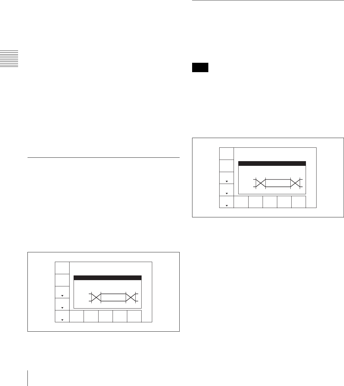
94 4-6 AUDIO Menu
Chapter 4 Menu Settings
3
Select the digital audio output signal for each channel.
TR1 to TR2: Output the audio signals recorded on
tracks 1 to 12.
4
Press the [F10] (EXIT) button.
This returns to the AUDIO menu.
Making output settings for individual channels
with the F buttons
By pressing any of the [F1] (SDOUT CH1 TR1) to [F8]
(SDOUT CH8 TR8) buttons, you can select the source
track for each channel.
Making input signal selections for individual
channels with the numeric buttons
1
Press the cursor T or t button, to align the cursor
with the channel for which you want to make the
selection.
2
Press the cursor R or r button, to select the source
channel to be output.
To return to the default settings
Press the cursor center button. The cursor item returns to
the default.
You can also make this setting using the VTR SETUP
menu item 836 “SD AUDIO OUTPUT EXCHANGE”.
4-6-5 Audio Transition Type
Selection for Digital Audio Editing
(AUDIO EDIT)
To select the digital audio transition type at edit points, use
the following procedure.
1
In the AUDIO menu, press the ALT button.
The AUDIO EDIT menu opens, and an edit image
window appears.
2
Press the ALT/[F1] (AUDIO EDIT) buttons to select
the transition type.
Each press of the buttons selects a transition type in the
order CUT t CROSS t FADE IN/OUT. At the
same time, the display in the edit image window
changes to reflect the selected type.
You can also make this setting using the VTR SETUP
menu item 317 “AUDIO EDIT MODE”.
4-6-6 Fade Processing Time
Selection for Digital Audio Editing
(FADE TIME)
To select the fade processing time for digital audio at edit
points, use the following procedure.
The fade processing time cannot be changed when the
audio transition type has been set to CUT with the ALT/
[F1] (AUDIO EDIT) buttons.
1
Press the ALT/[F1] (AUDIO EDIT) buttons, and select
CROSS or FADE IN/OUT.
The FADE TIME menu appears.
2
Press the ALT/[F2] (FADE TIME) button to select the
fade time.
Each press of the button changes the setting in the
range 5 ms to 115 ms. At the same time, the display in
the edit image window changes to reflect the selected
time.
You can also make this setting using the VTR SETUP
menu item 811 “DIGITAL AUDIO FADE TIME”.
AUDIO
EDIT
cross
FADE
TIME
50ms
REPLCE
MODE
ANALOG
REPLCE
PITCH
GROUP
AUDIO EDIT/FADE TIME
AUDIO EDIT : CROSS FADE
FADE TIME : 50ms
PB
INPUT
IN OUT
Note
AUDIO
EDIT
cross
FADE
TIME
50ms
REPLCE
MODE
ANALOG
REPLCE
PITCH
GROUP
AUDIO EDIT/FADE TIME
AUDIO EDIT : CROSS FADE
FADE TIME : 50ms
PB
INPUT
IN OUT
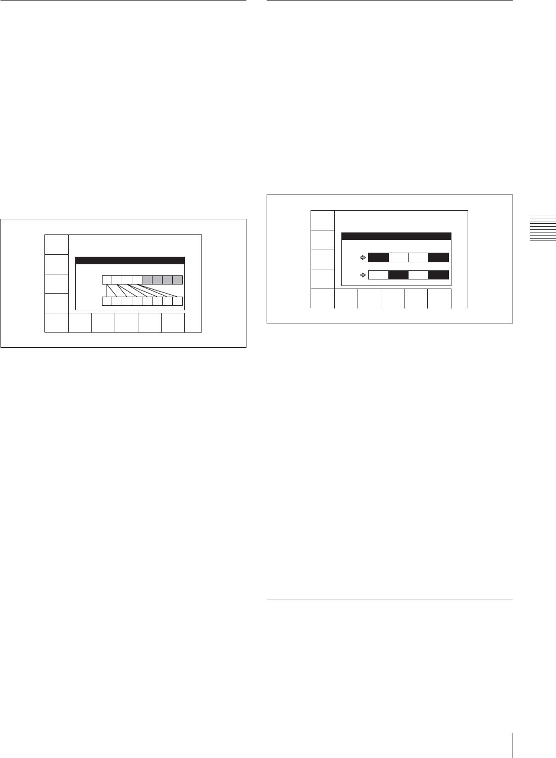
95
4-6 AUDIO Menu
Chapter 4 Menu Settings
4-6-7 External Device Digital Audio
Edit Preset Command Replace Mode
Selection (AUDIO EDIT PRESET
REPLACE)
You can replace the channel settings for digital audio edit
preset commands received from editors and other external
devices. For example, some devices are capable of issuing
digital audio edit preset commands only for channels 1 to
4 (CH1 to CH4). This function allows such devices to
control channels 1 to 8 on this unit.
1
Press the ALT/[F3] (REPLACE MODE) buttons.
The REPLACE MODE menu appears, together with a
REPLACE image window.
2
Press the [F1] (REPLACE MODE) button.
Each press of the button changes the setting in the
order “normal t parallel t reverse t stereo”. At
the same time, the image of the channels
corresponding to the command changes to reflect the
selected setting.
3
Press the [F10] (EXIT) button.
This returns to the AUDIO menu screen.
You can also make this setting using the VTR SETUP
menu item 311 “EDIT PRESET REPLACE MODE
SELECT”.
See “4-6-8 External Device Analog Audio Edit Preset
Command Replace Mode Selection (ANALOG AUDIO
EDIT REPLACE)” (page 95) for information about
settings for audio edit preset control of channels 9 to 12.
4-6-8 External Device Analog Audio
Edit Preset Command Replace Mode
Selection (ANALOG AUDIO EDIT
REPLACE)
You can replace the channel settings for analog audio edit
preset commands received from editors and other external
devices. This function allows such devices to control
channels 9 to 12 on this unit.
1
Press the ALT/[F4] (ANALOG REPLACE) buttons.
The ANALOG AUDIO EDIT REPLACE menu
appears, together with a REPLACE image window.
2
Use the [F1] (ANAREP CH9), [F2] (ANAREP CH10),
[F3] (ANAREP CH11), [F4] (ANAREP CH12)
buttons to specify whether to control channels 9 to 12
with edit preset commands for analog channels 1 and
2.
The image of the corresponding channels changes to
reflect the settings.
3
Press the [F10] (EXIT) button.
This returns to the AUDIO menu screen.
You can also make this setting using the VTR SETUP
menu item 312 “ANALOG AUDIO EDIT PRESET
REPLACE”.
See “4-6-7 External Device Digital Audio Edit Preset
Command Replace Mode Selection (AUDIO EDIT
PRESET REPLACE)” (page 95) for information about
settings for audio edit preset control of channels 1 to 8.
4-6-9 PITCH GROUP Selection
(PITCH CORRECTION GROUP
SELECT)
When pitch correction is performed during program play
and play at a different frequency (23.98 frame y 24 frame,
REPLCE
MODE
stere
EXIT
AUDIO EDIT PRESET REPLACE
REPLACE MODE : STEREO
COMMAND
CH1 CH2 CH3 CH4 CH5 CH6 CH7 CH8
PRESET
CH1 CH2 CH3 CH4 CH5 CH6 CH7 CH8
ANAREP
CH9
ch1
ANAREP
CH10
ch2
ANAREP
CH11
nodef
ANAREP
CH12
ch1+2
EXIT
ANALOG AUDIO EDIT REPLACE
CMD PRESET
ANA
CH1
CH9 CH10 CH11 CH12
CH9 CH10 CH11 CH12
ANA
CH2

96 4-6 AUDIO Menu
Chapter 4 Menu Settings
23.98/24 frame y 25 frame, 29.97 frame y 30 frame), you can
set up group relations between audio channels.
1
Press the ALT/[F5] (PITCH GROUP) buttons.
The PITCH CORRECTION GROUP SELECT menu
appears, together with an image window of channels
groups for pitch correction.
2
Use the [F1] (CH1) to [F8] (CH8) buttons and the
ALT/[F1] (CH9) to ALT/[F4] (CH12) buttons to group
channels (Group-A to F, OFF).
The image of channels belonging to each group
changes to reflect the selections.
3
Press the [F10] (EXIT) button.
This returns to the AUDIO menu screen.
You can also make this setting using the VTR SETUP
menu item 817 “PITCH CORRECTION GROUP select”.
CH1
Grp_A
CH2
Grp_A
CH3
Grp_B
CH4
Grp_B
CH5
Grp_C
CH7
Grp_D
CH8
Grp_D
EXITCH6
Grp_C
PITCH CORRECTION GROUP SELECT
Grp-A:
CH1 CH2
Grp-B:
CH3 CH4
Grp-C:
CH5 CH6
Grp-D:
CH7 CH8
Grp-E:
CH9 CH10
Grp-F:
CH11 CH12
OFF :
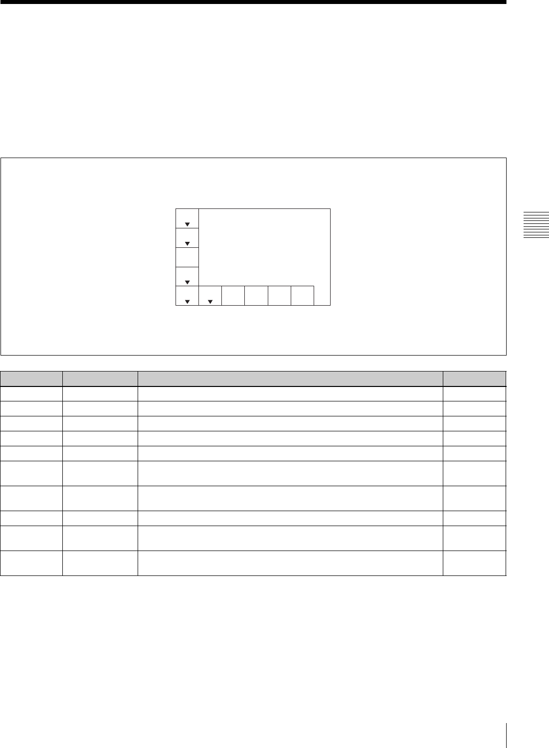
97
4-7 SET UP Menu
Chapter 4 Menu Settings
4-7 SET UP Menu
In the SET UP menu, you can store and recall menu
settings to and from the VTR memory banks and memory
stick, register items to the PF menu, and set items in the
VTR SETUP menu and PANEL SETUP menu.
For details on storing and recalling data to or from the
VTR memory banks or memory stick, and registering items
to the PF menus, see “4-1 Registering and Storing Menu
Settings” on page 37.
To activate the SET UP menu
Press the SET UP button.
To change the SET UP menu page
Press the ALT button.
Selecting remote operation mode
When operating the VTR with an external device, set the
ALT/[F7] (REMOTE NET) buttons, ALT/[F8] (REMOTE
9-PIN) buttons or ALT/[F9] (REMOTE 50-PIN) buttons to
“on”.
When the ALT/[F7] (REMOTE NET) buttons are set
to “on”
You can operate the VTR from a computer or similar
through the network to which the ETHERNET connector
is connected.
Button Indication Function Settings
[F1] VTR BANK See “4-1-4 VTR Memory Bank Function” on page 39.
[F2] MEMORY CARD See “4-1-5 Memory Stick Operations” on page 41.
[F4] PF ASSIGN See “4-1-3 Registering Items to the VTR SETUP Menu” on page 38.
[F5] PANEL SETUP See “4-7-2 PANEL SETUP Menu” on page 100.
[F6] VTR SETUP See “4-7-1 VTR SETUP Menu” on page 98.
ALT/[F1] DEFAULT VTR
BANK
See “4-1-10 Saving and Recalling DEFAULT Settings on a Bank” on
page 48.
ALT/[F2] DEFAULT
MEMORY CARD
See “4-1-11 Saving and Recalling DEFAULT Settings in a “Memory Stick””
on page 48.
ALT/[F7] REMOTE NET Selects access from the ETHERNET connector. on, off
ALT/[F8] REMOTE 9-PIN Selects remote operation using a device connected to the REMOTE 1-
IN(9P) or REMOTE 1-I/O(9P) connector.
on, off
ALT/[F9] REMOTE 50-PIN Selects remote operation using a device connected to the REMOTE 2
PARALLEL I/O(50P) connector.
on, off
VTR
BANK
MEMORY
CARD
PF
ASSIGN
PANEL
SETUP
VTR
SETUP
[F1]VTR BANK: Copy data between
current setup and 8 banks.
[F2]MEMORY CARD: Copy data
between VTR and memory card.
[F4]PF1&2 ASSIGN: Assign PF1/PF2
menu function keys.
[F5]PANEL SETUP; Panel setting
[F6]VTR SETUP; VTR current setup
“V” indicates that more than one menu page exists.
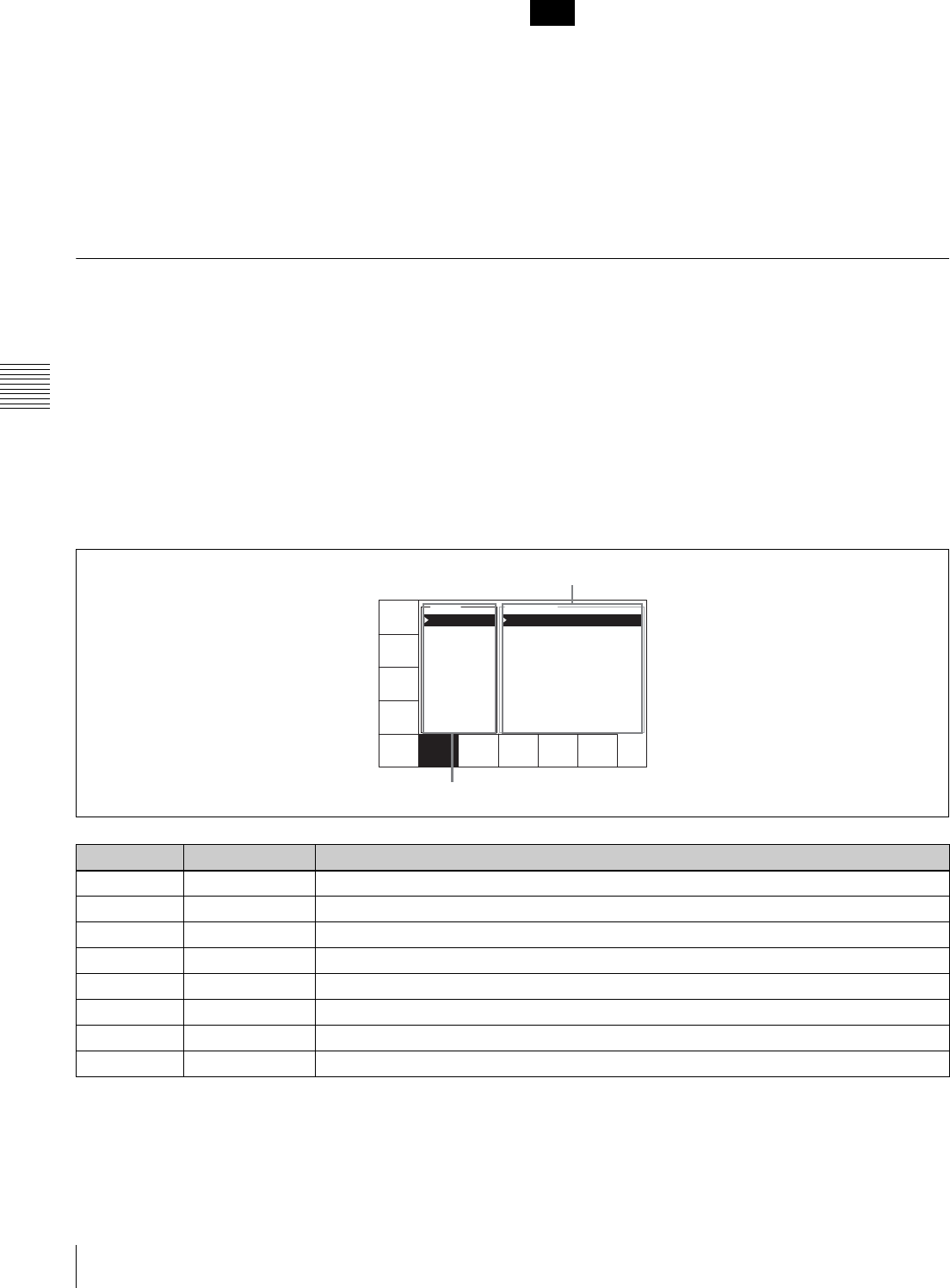
98 4-7 SET UP Menu
Chapter 4 Menu Settings
When the ALT/[F8] (REMOTE 9-PIN) buttons are
set to “on”
You can operate the VTR with a device connected to the
REMOTE 1-IN(9P) or REMOTE 1-I/O(9P) connector.
When the ALT/[F9] (REMOTE 50-PIN) buttons are
set to “on”
You can operate the VTR with a device connected to the
REMOTE 2 PARALLEL I/O(50P) connector.
When operating the VTR through an external device with
the ALT/[F8] or ALT/[F9] buttons set to “on”, all of the
tape operation and editing buttons are disabled, with the
exception of the STOP and EJECT buttons. You may also
set the VTR so that all buttons are enabled or disabled.
Perform this setting using the VTR SETUP menu item 008
“LOCAL FUNCTION ENABLE”. You cannot, however,
disable the menu and remote operation mode selection
buttons.
4-7-1 VTR SETUP Menu
All menu items required for setting up the VTR operating
conditions are displayed in the scrollable VTR SETUP
menu.
For HOME, TC, VIDEO, AUDIO, PF1, and PF2,
including the screens displayed by pressing the ALT
button, you can register about 120 menu items.
For details on the VTR SETUP menu items, see the
Appendix “Menu List” on page 141.
For details of the PF assign menu, see “4-1-3 Registering
Items to the VTR SETUP Menu” on page 38.
To activate the VTR SETUP menu
Press the SET UP button, then press the [F6] (VTR
SETUP) button.
Note
Button Indication Function
[F1] PREV PAGE Moves to the beginning of the previous category.
[F2] NEXT PAGE Moves to the beginning of the next category.
[F5] CATEGORY Display by category
[F6] NAME Display in alphabetical order
[F7] SCROLL Scrolling display of all menus
[F8] CHANGE DATA Changes the setting.
[F9] CANCEL Cancels the setting operation.
[F10] SAVE/EXIT Sets the value and exits the VTR SETUP menu.
PREV
PAGE
NEXT
PAGE
CATEGO
RY
SCROLL CHANGE
DATA
CANCEL SAVE/
EXIT
NAME
INDEX TAPE EDIT
A... 322:A PREVIEW - SSS
B... 910:A-LINE 1035 - CONV
C... 911:A-LINE 1080 - CONV
D... 401:AFTER CUE - stop
E... 116:ALARM BEEP - high
F... 835:ANA-OUT EXCG- (SUB)
G... 921:ASPECT FLAG - off
H... 815:AU OUT PHAS - prst
I... 821:AUDIO AVI - off
J... 317:AUDIO EDIT - cut
Item window
Category/index window
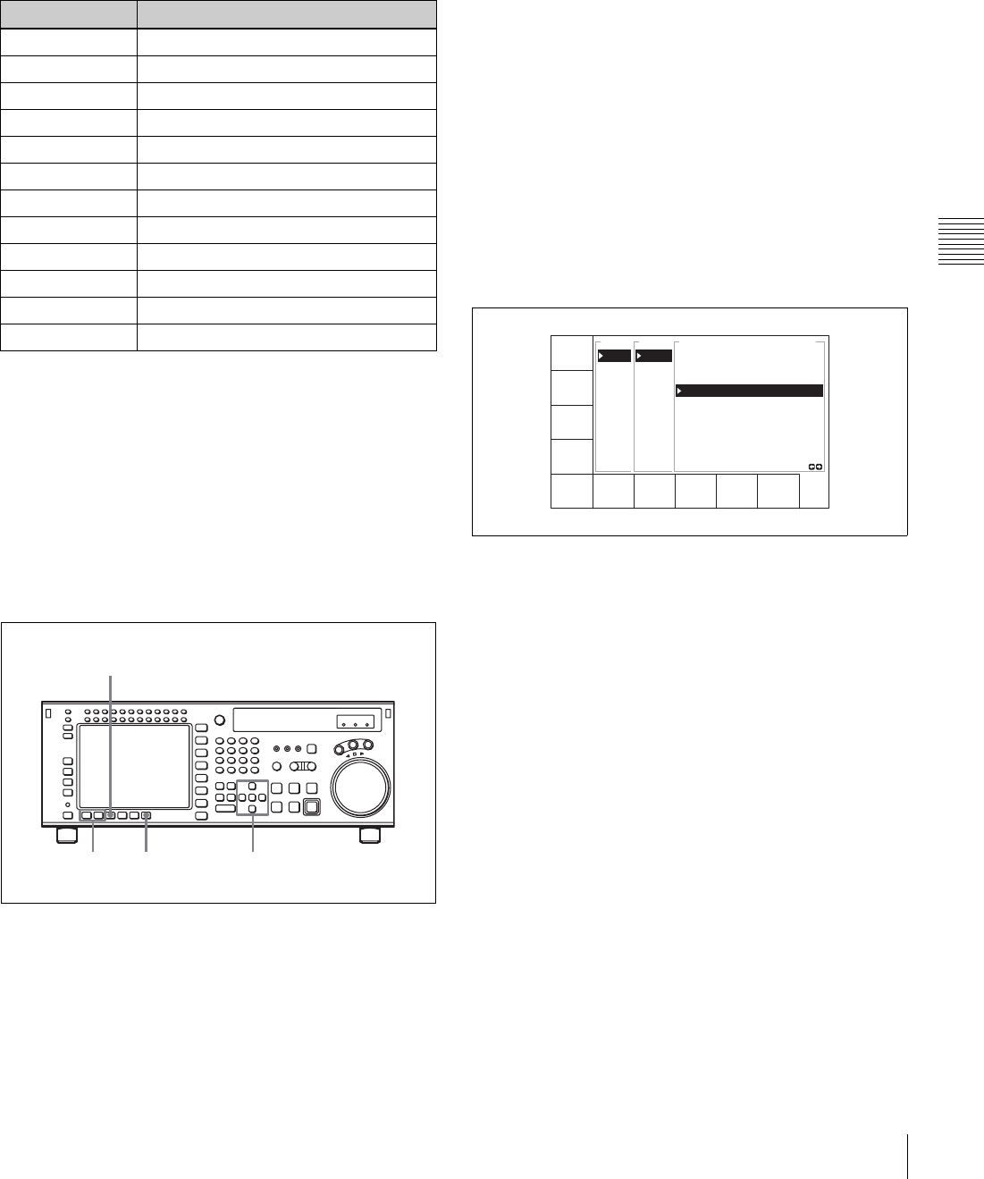
99
4-7 SET UP Menu
Chapter 4 Menu Settings
Scrolling items in the VTR SETUP menu
Press the R and r buttons to scroll the items in the VTR
SETUP menu.
To search the menu by category
Items in the VTR SETUP menu are divided into categories
according to type of settings they perform.
To change the menu display
Press any of the following buttons, to change the menu
display.
[F5] (CATEGORY) button: Display the menus by
category
[F6] (NAME) button: Display all menus in alphabetical
order
[F7] (SCROLL) button: Display all menus in numerical
order
Changing settings
1
Press one of the [F5] (CATEGORY), [F6] (NAME),
and [F7] (SCROLL) buttons.
This changes the menu display.
To change the category
Do one of the following:
• Press the T button to make the categories window
active, and select the category with the R and r
buttons.
• Press the t button to make the item window
active, and press the [F1] (PREV PAGE) or [F2]
(NEXT PAGE) button.
2
Press the t button to make the item window active,
then use the cursor R and r button, or the MULTI
CONTROL knob, to align the cursor with the item to
be changed.
To speed up cursor movement
Hold down the SFT button, and press the cursor R and
r button.
3
Press the [F8] (CHANGE DATA) button or the cursor
t button.
A window for changing the setting value appears.
4
With the [F8] (CHANGE DATA) button, or the cursor
R and r button, or the MULTI CONTROL knob, select
the setting value.
When subitems are displayed, use the cursor R and r
button, or the MULTI CONTROL knob to select the
subitem to be changed, then press the [F8] (CHANGE
DATA) button repeatedly.
To return to the DEFAULT values, press the center
cursor button or the MULTI CONTROL knob.
5
Press the [F10] (SAVE/EXIT) button or the cursor T
button.
This saves the change, and closes the window.
About the unit’s behavior when the MULTI
CONTROL knob is pressed
You can set item 132 “KNOB MODE” in the VTR
SETUP menu to “move window” to select moving
between windows as the action when the knob is
pressed.
Menu number Category
Nos. 001 to … Items related to VTR operations
Nos. 101 to … Items related to operation panels
Nos. 201 to … Items related to remote interface
Nos. 301 to … Items related to editing
Nos. 401 to … Items related to prerolling
Nos. 501 to … Items related to recording protection
Nos. 601 to … Items related to the time code
Nos. 701 to … Items related to the video control
Nos. 801 to … Items related to the audio control
Nos. 901 to … Items related to digital process
Nos. A01 to … Items related to pulldown control
Nos. T01 to … Other
2,51 5,6
3,4
CHANGE
DATA
SAVE/
EXIT
CATEG
VTR D
PANEL
REMOT
EDITR
PAERO
TP PF
TIME
VIDEO
VIDEO
AUDIO
VTR C
001:P
002:R
003:R
005:S
006:E
007:S
008:L
009:L
017:P
018:A
VTR CONTROL 001
PRE-READ
on
off *

100 4-7 SET UP Menu
Chapter 4 Menu Settings
6
To continue with changing the settings, repeat steps 1
to 5.
7
Press the [F10] (SAVE/EXIT) button.
This saves all the changes, and returns to the SET UP
menu screen.
To check the items with changed settings
In VTR SETUP menu item 131 “CHANGED MENU
HIGHLIGHT”, set ITEM SETTING to “on”.
Items for which the setting values are different from the
DEFAULT values appear in the VTR SETUP screen in
yellow.
To change the DEFAULT values in a menu item
1
Use the cursor t button to make the item window
active, then with the cursor R and r buttons or the
MULTI CONTROL knob, move the cursor to the item
to be changed.
2
Press the [F7] (CHANGE DATA) button or the cursor
t button.
This opens a window for changing the setting.
For a sub item, further press the [F7] (CHANGE
DATA) button or the cursor t button, to open the
window for changing the setting.
3
With the [F7] (CHANGE DATA) button, the cursor R
or r button, or the MULTI CONTROL knob, change
the setting.
4
Holding down the SET and ENTRY buttons at the
same time, press the center cursor button.
This saves the current settings as new DEFAULT
values for CURRENT DEFAULT.
The asterisks “*” indicating the DEFAULT values
move.
Note
If you press the center cursor button first, the setting
values return to the PRESET values before
CURRENT DEFAULT is overwritten, and it is not
possible to change DEFAULT correctly.
To return the DEFAULT values to the factory
default PRESET values
Holding down the CLR and ENTRY buttons at the
same time, press the center cursor button.
This saves the factory default PRESET values as the
DEFAULT values for CURRENT DEFAULT.
5
Reset the current setting values if necessary, then press
the [F10] (SAVE/EXIT) button.
You can save the changed CURRENT DEFAULT
data set in DEFAULT VTR BANK or a “Memory
Stick”.
For details, see see “4-1-10 Saving and Recalling
DEFAULT Settings on a Bank” on page 48 and see “4-1-
11 Saving and Recalling DEFAULT Settings in a
“Memory Stick”” on page 48.
To check the items for which DEFAULT values
have been changed
In VTR SETUP menu item 131 “CHANGED MENU
HIGHLIGHT”, set DEFAULT SETTING to “on”.
Items for which the DEFAULT values are different from
the factory setting values (FACTORY PRESET) values
have the item number (or item name for a subitem) in the
VTR SETUP screen shown in yellow.
4-7-2 PANEL SETUP Menu
The PANEL SETUP menu is used to set the operation
conditions of the upper and lower control panels.
To activate the PANEL SETUP menu
Press the SET UP button, then press the [F5] (PANEL
SETUP) button.
KEYINH
off
PLAY LOCK
ALARM
BEEP
high
SCREEN
SAVER
10min
SCREEN
SAVER S
EXITKEY
BEEP
off

101
4-7 SET UP Menu
Chapter 4 Menu Settings
Disabling button operations on the upper/
lower control panel
Set the [F1] (KEYINH) button to “on”.
Setting the confirmatory beep after button
operations
Press the [F6] (KEY BEEP) button repeatedly.
high: loud confirmatory beep
mid: confirmatory beep
low: quiet confirmatory beep
off: no confirmatory beep
Setting the alarm sound when an error
occurs
Press the [F7] (ALARM BEEP) button repeatedly.
high: loud alarm sound
mid: alarm sound
low: quiet alarm sound
off: no alarm sound
Setting the time until the color display
screen saver is activated
Press the [F8] (SCREEN SAVER) button repeatedly.
3min: The screen saver is activated 3 minutes after the last
button operation.
10min: The screen saver is activated 10 minutes after the
last button operation.
60min: The screen saver is activated 60 minutes after the
last button operation.
off: The screen saver is not activated.
Setting the information display screen
saver
Press the [F9] (SCREEN SAVER S) button.
on: The screen display is periodically switched between
normal video and reverse video.
off: The screen saver is not activated.
Button Indication Function Settings
[F1] KEYINH Disables all button operations. on, off
[F6] KEY BEEP Sets the keyboard sound. high, mid, low, off
[F7] ALARM BEEP Sets the alarm. high, mid, low, off
[F8] SCREEN
SAVER
Sets the color display screen-saver. 3min, 10min, 60min, off
[F9] SCREEN
SAVER S
Sets the information display screen-saver. on, off
[F10] EXIT Returns to the PANEL SETUP menu.
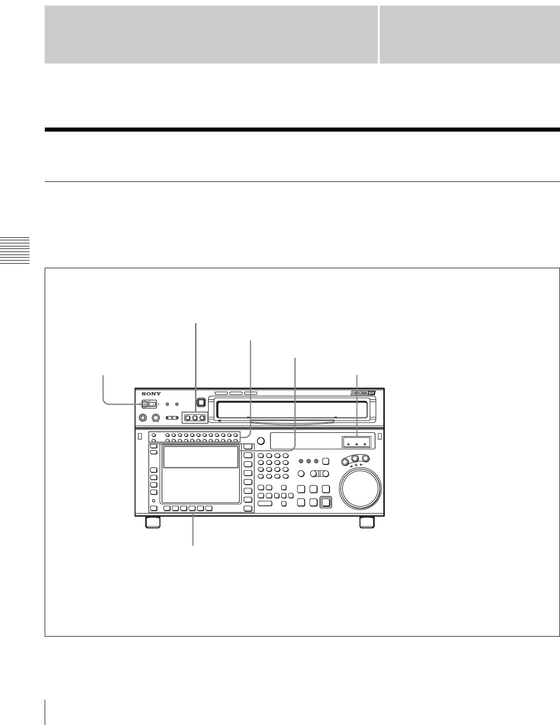
Chapter 5
102 5-1 Preparing for Recording
Chapter 5 Recording/Playback
Recording/Playback
5-1 Preparing for Recording
5-1-1 Setting Switches and Menus
Before recording, set the switches and menus as shown in
the diagram below.
For details, see the pages indicated in the parentheses.
SRW-5000
HD DIGITAL VIDEO CASSETTE RECORDER
REMOTE buttons: None of these buttons light up.
MONITOR SELECT buttons: Audio channels to be monitored (page 103)
Recording level indication: Reference level or appropriate recording level (page 104)
POWER switch: ON Indicators: Check the reference signal.
Menu settings
[F2] (REC INH) button in the HOME menu: off
[F1] (TIMER SEL) button in the TC menu: Select the time data to be displayed.
[F6] (REGENE SOURCE) button in the TC menu: int-LTC, int-VITC, ext-LTC, SDI-V, SDI-L (page 56)
[F7] (TCG MODE) button in the TC menu: regene, prst, auto (page 56)
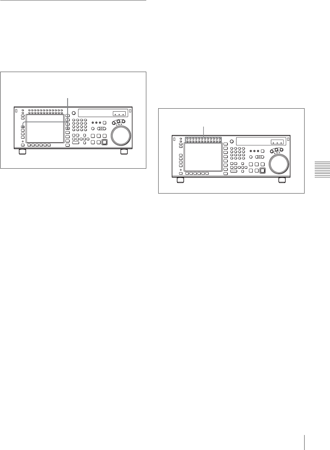
103
5-1 Preparing for Recording
Chapter 5 Recording/Playback
5-1-2 Selecting Audio Signals
This section describes how to select the audio signals for
input and monitoring.
Selecting the audio input signals
Proceed as follows to select the audio input signal and
channels.
1
Press the AUDIO button, and in the AUDIO menu
press the [F1] (AUDIO IN) button, to access the
AUDIO INPUT menu.
2
Make the audio input signal settings for each channel.
SDI: audio signal input from the HD SDI INPUT A/B
connector
AES/EBU: audio signal input from the DIGITAL I/O
(AES/EBU) connector
To make settings for individual channels with the
F buttons
By pressing any of the [F1] (A-IN CH1) to [F8] (A-IN
CH8) buttons in the AUDIO INPUT menu, and the [F1]
(A-IN CH9) to [F4] (A-IN CH12) buttons in the
ALT+AUDIO screen obtained by pressing the ALT
button, you can select the type of input signal for each
channel.
To make input signal selections for individual
channels with the numeric buttons
1
Press the cursor T or t button, to align the cursor
with the channel for which you want to make the
selection.
2
Press the cursor R or r button, to select the signal.
To return to the default settings
Press the cursor center button.
To select the same input signal simultaneously
on all twelve channels
Press the [F9] (A-IN ALL) button.
This changes the input signal simultaneously on all twelve
channels.
You can also make this setting using the VTR SETUP
menu item 830 “AUDIO INPUT SELECT”.
Selecting audio signals to be monitored
With the MONITOR L or R buttons at the upper left of the
control panel, switch the audio signal output from the
PHONES jack and MONITOR OUTPUT L/R connectors
as follows.
1
Check the audio level display area in the color display,
and make sure that the unit is not in the REC LEVEL/
PB LEVEL setting state (with red or blue vertical lines
appearing on the left and right of the audio level
meter).
The channels for which the signals are currently being
monitored are shown by reverse video characters “L”
and “R” below the audio level meter.
2
Press the buttons corresponding to each channel, to
light the L/R reverse video indications below the audio
level meter, and specify channels 1 to 12 with the
MONITOR L or R button (both L and R can also be
specified).
This setting can also be made using the VTR SETUP
menu items 807 “AUDIO MONITOR-L select” and
808 “AUDIO MONITOR-R select”.
To adjust the audio output level of the PHONES
jack
Rotate the PHONES level control on the upper control
panel.
1
2
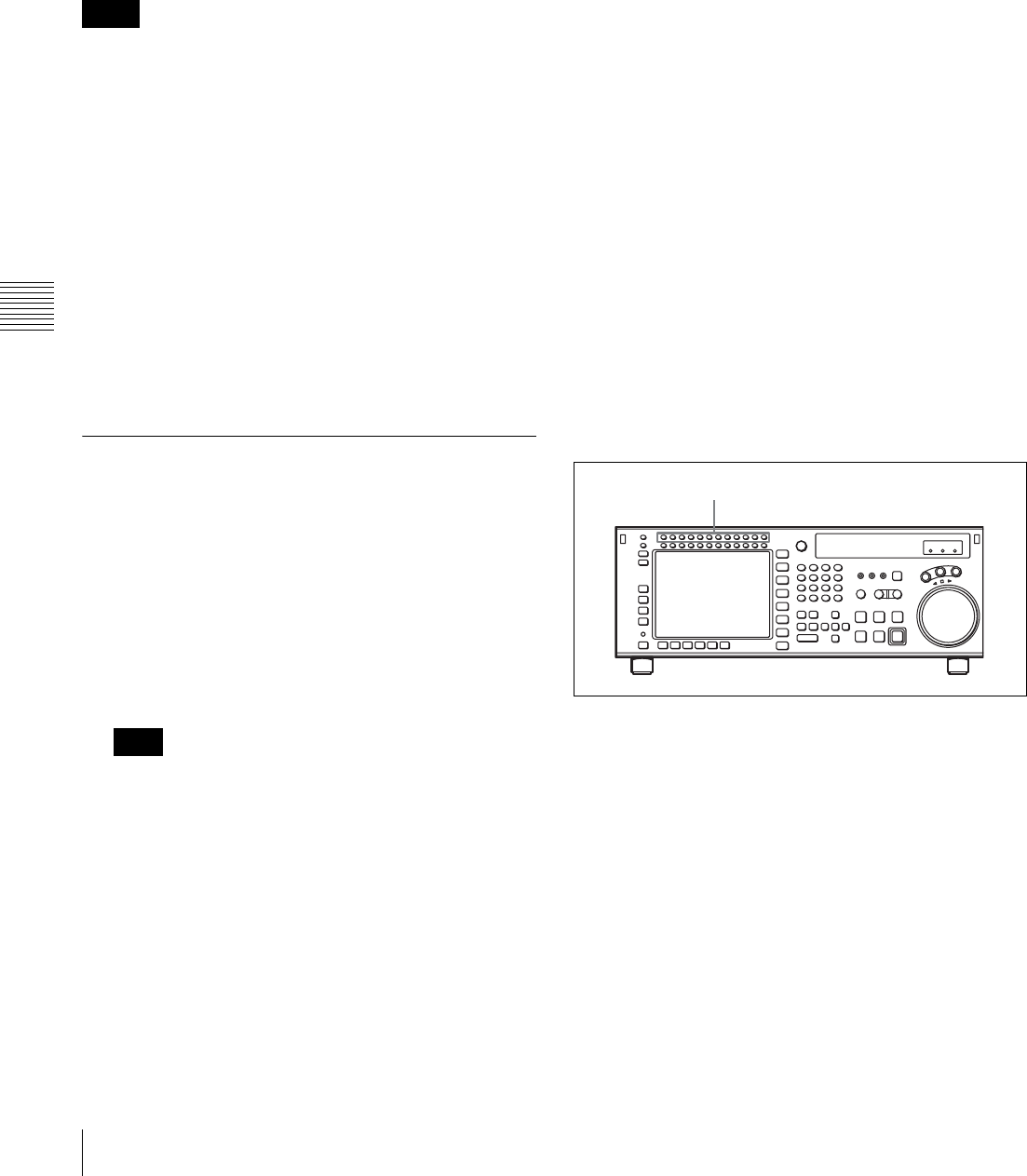
104 5-1 Preparing for Recording
Chapter 5 Recording/Playback
Selecting non-audio data as the audio
input signal
Do the procedure below to select non-audio data such as a
Dolby1) E or Dolby Digital (AC-32)) signal as the audio
input signal. Use the VTR SETUP menu item 831 “NON
AUDIO SELECT” to select the audio input signal.
1) Dolby is a trademark of Dolby Laboratories.
2) AC-3 is a trademark of Dolby Laboratories.
The following processes are performed for the selected
channels.
• For the input signal, the setting of the VTR SETUP menu
item 831 “NON AUDIO SELECT” takes precedence
over that of the menu item 830 “AUDIO INPUT
SELECT ”.
• For the audio level meters, the whole region lights.
Also, below the input signal display, the word “DATA”
appears in white.
• The analog audio outputs (main line/monitor/
headphones) are muted.
• The audio recording level adjustment itself is possible
for the channel for which “NON AUDIO” is selected,
but the setting does not affect the recording or playback
of DATA.
• Non-audio input channels are selected in stereo pairs.
5-1-3 Adjusting the Recording Level
Adjusting the Recording Level
1
Press the REC LEVEL button at the upper left of the
control panel to enter the REC LEVEL adjustment
mode.
A vertical red line appears at the left of the audio level
meter for each channel, indicating the REC LEVEL
adjustment mode.
The adjustment cannot be made with the VIDEO menu
and the VTR SETUP menu.
2
Press the button for the channel for which you want to
carry out the adjustment (common with MONITOR
L), to make the channel active.
An orange border appears around the audio level
meter, indicating that it is active.
3
Use the cursor buttons to make the adjustment.
To escape from the REC LEVEL adjustment mode
Press the REC LEVEL mode button at the upper left of the
control panel once more. The vertical red line at the left of
the audio level meter for each channel disappears or turns
white.
To record at the reference level
In the REC LEVEL adjustment mode, make the channel
active, then press the MULTI CONTROL knob. The
setting becomes the reference value. Press once more to
return to the immediately previous value. Press once more
again to return to the reference value. You can also return
to the reference value with the cursor center button. When
you exit the REC LEVEL adjustment mode, a vertical
white line on the left of the audio level meter is not
displayed.
To record with manual adjustment
In the REC LEVEL adjustment mode, make the channel
active, then at the mean volume make the adjustment with
the MULTI CONTROL knob or cursor R and r buttons so
that the audio level meter is close to the reference 0 dB
level. When you exit the REC LEVEL adjustment mode,
the vertical white line on the left of the audio level meter
and a horizontal red line indicating the setting are
displayed, indicating that the recording level is subject to
manual adjustment.
You can also carry out the recording level adjustment
using the VTR SETUP menu item 832 “ AUDIO REC
LEVEL”.
Selecting the display range of the audio
level meters
You can switch the range of audio level meter display by
pressing the FULL/FINE button on the lower control
panel.
Notes
Note
MONITOR L buttons
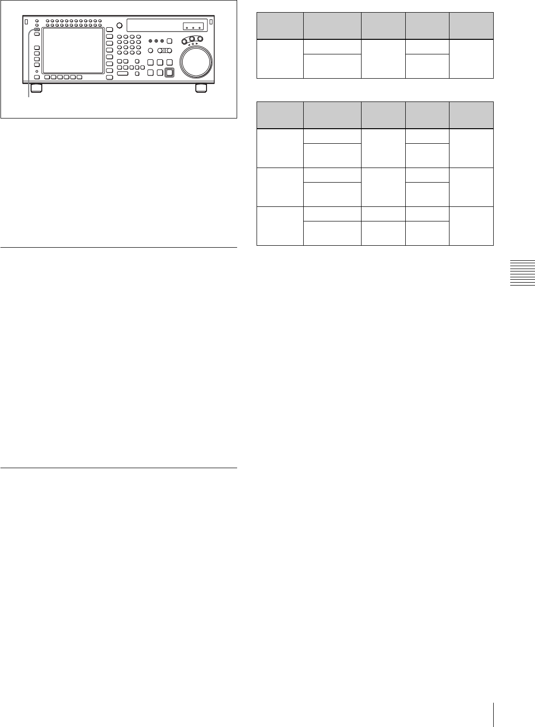
105
5-1 Preparing for Recording
Chapter 5 Recording/Playback
FULL mode: The meter range is –60 to 0 dB or –40 to
+20 dB.
FINE mode: The meter scale is enlarged, and the signal
level is indicated in 0.25 dB steps, with the reference
marker indicated in the middle of each meter.
The display range of the audio level meters in FULL mode
can be set using the VTR SETUP menu item 814 “LEVEL
METER SCALE”.
5-1-4 Simultaneously Monitoring
Playback of Video and Audio Signals
Being Recorded
Monitoring signals being recorded
Using the VTR SETUP menu item 017 “PB/EE SELECT
MENU”, you can make a setting so that the audio and
video signals currently being recorded are simultaneously
checked.
To check video and audio signals during
recording
Set the sub item “REC” of the VTR SETUP menu item 017
“PB/EE SELECT MENU” to “PB/PB”. Both audio and
video playback signals are output.
5-1-5 Audio Level Meter Display
Modes
The audio level meter display changes for each mode
depending on the current system recording mode settings
and the type of cassette in use.
SRW-5000:
SRW-5500:
FULL/FINE button
REC
format
Cassette
used
EE PB EJECT
HDCAM-
SR
HDCAM-SR 12ch 12ch 12ch
HDCAM/
D-BETACAM
4ch+CUE
REC
format
Cassette
used
EE PB EJECT
HDCAM-
SR
HDCAM-SR 12ch 12ch 12ch
HDCAM/
D-BETACAM
4ch+CUE
HDCAM HDCAM-SR 4ch+CUE 12ch 4ch+CUE
HDCAM/
D-BETACAM
4ch+CUE
AUTO HDCAM-SR 12ch 12ch 12ch
HDCAM/
D-BETACAM
4ch+CUE 4ch+CUE
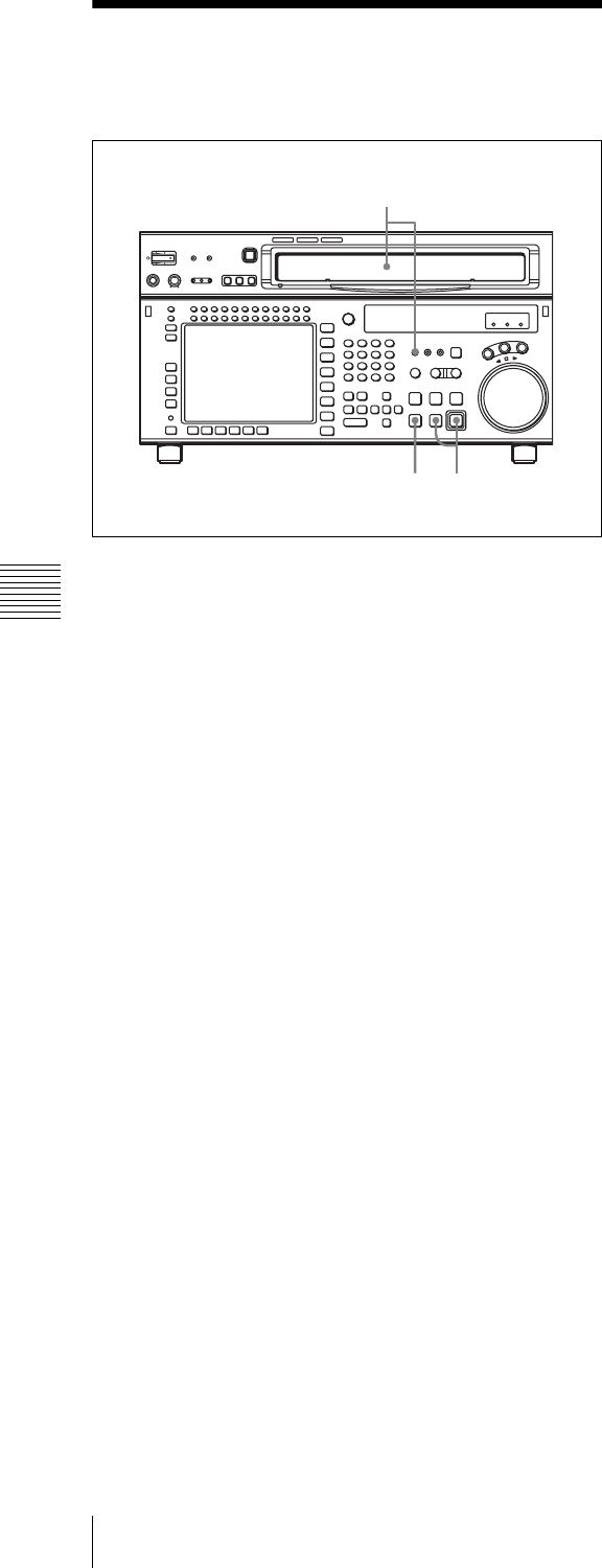
106 5-2 Recording
Chapter 5 Recording/Playback
5-2 Recording
To record, follow the procedure below.
1
Check that the REC INHIBIT indicator is off, then
insert a cassette.
For details on inserting a cassette, see “3-3-2
Inserting and Ejecting Cassettes” on page 34.
2
Press the PLAY button while holding down the REC/
EDIT button.
Recording starts and the SERVO indicator lights up to
indicate that the servo is locked.
3
Press the STOP button to stop recording.
If the recording continues to the end of the tape
If the VTR SETUP menu item 407 “AUTO REWIND” is
set to “on”, then the tape automatically rewinds to the
beginning and stops.
1
32
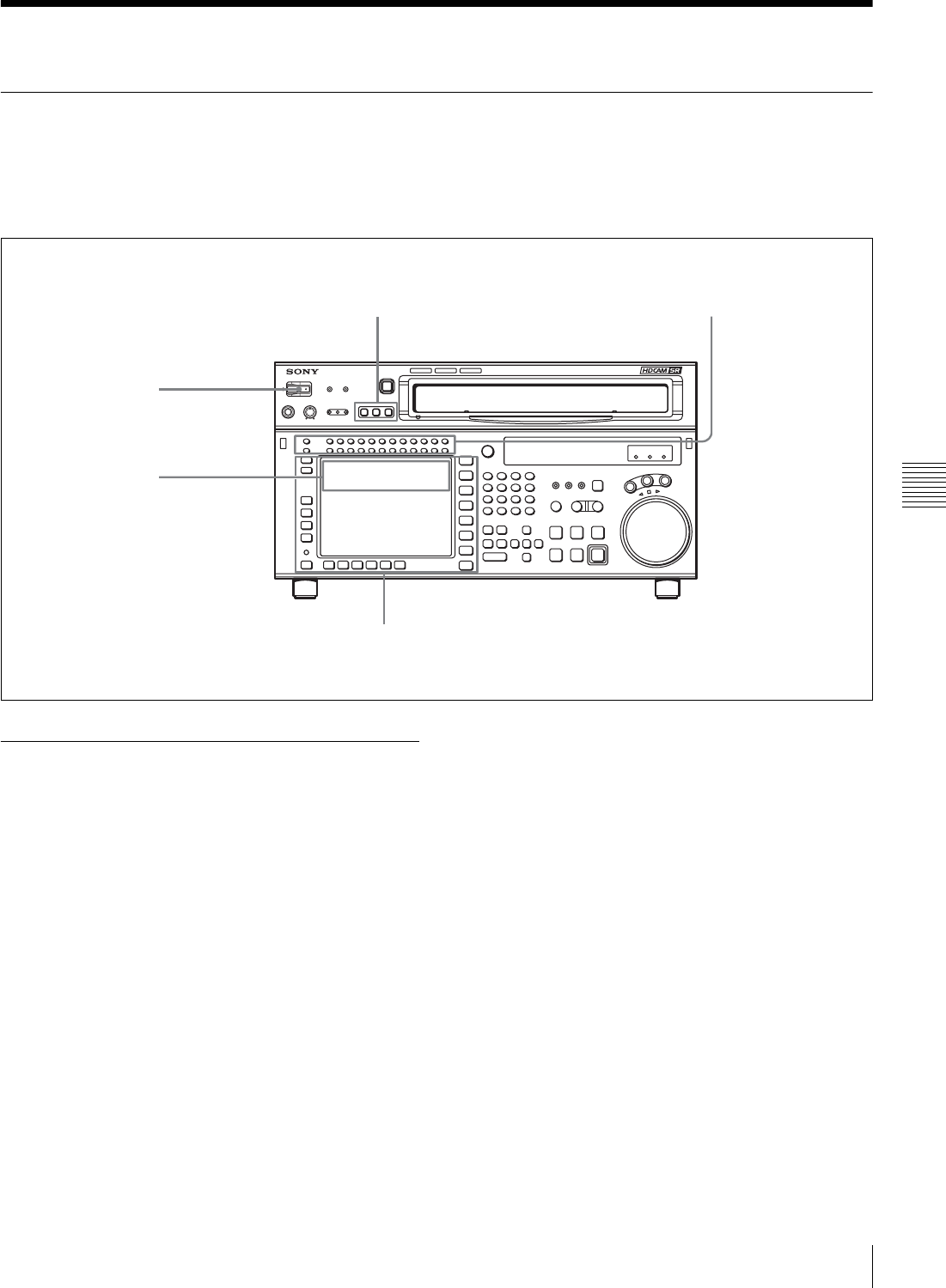
107
5-3 Preparing for Playback
Chapter 5 Recording/Playback
5-3 Preparing for Playback
5-3-1 Setting Switches and Menus
Before starting playback, set the switches and menus as
shown in the diagram below.
For details, see the pages indicated in the parentheses.
5-3-2 Adjusting the Audio Playback
Level
1
Press the PB LEVEL button at the upper left of the
control panel to enter the PB LEVEL adjustment
mode.
A vertical blue line appears at the right of the audio
level meter for each channel, indicating the PB
LEVEL adjustment mode.
2
Press the button for the channel for which you want to
carry out the adjustment (common with MONITOR
R), to make the channel active.
An orange border appears around the audio level
meter, indicating that it is active.
3
Make the adjustment, using the MULTI CONTROL
knob or cursor buttons.
To escape from the PB LEVEL adjustment mode
Press the PB LEVEL button at the upper left of the control
panel once more. The vertical blue line at the right of the
audio level meter for each channel disappears or turns
white.
To output at the preset level (for a level recorded
at reference 0 dB, outputting at +4 dBm)
In the PB LEVEL adjustment mode, make the channel
active, then press the MULTI CONTROL knob. The
setting becomes the preset value. Press once more to return
to the immediately previous value. Pressing once more
again to return to the preset value. You can also return to
the preset value with the cursor center button. When you
exit the PB LEVEL adjustment mode, a vertical white line
on the right of the audio level meter is not displayed.
For details on changing the factory-set reference output
level, refer to the Installation Manual.
SRW-5000
HD DIGITAL VIDEO CASSETTE RECORDER
MONITOR SELECT buttons: Audio
channels to be monitored (page 103)
POWER switch: ON
PB level controls:
Playback level
Menu settings
[F1] (TIMER SEL) button in the TC menu: Select the time data to be displayed.
REMOTE buttons: None of
these buttons light up.
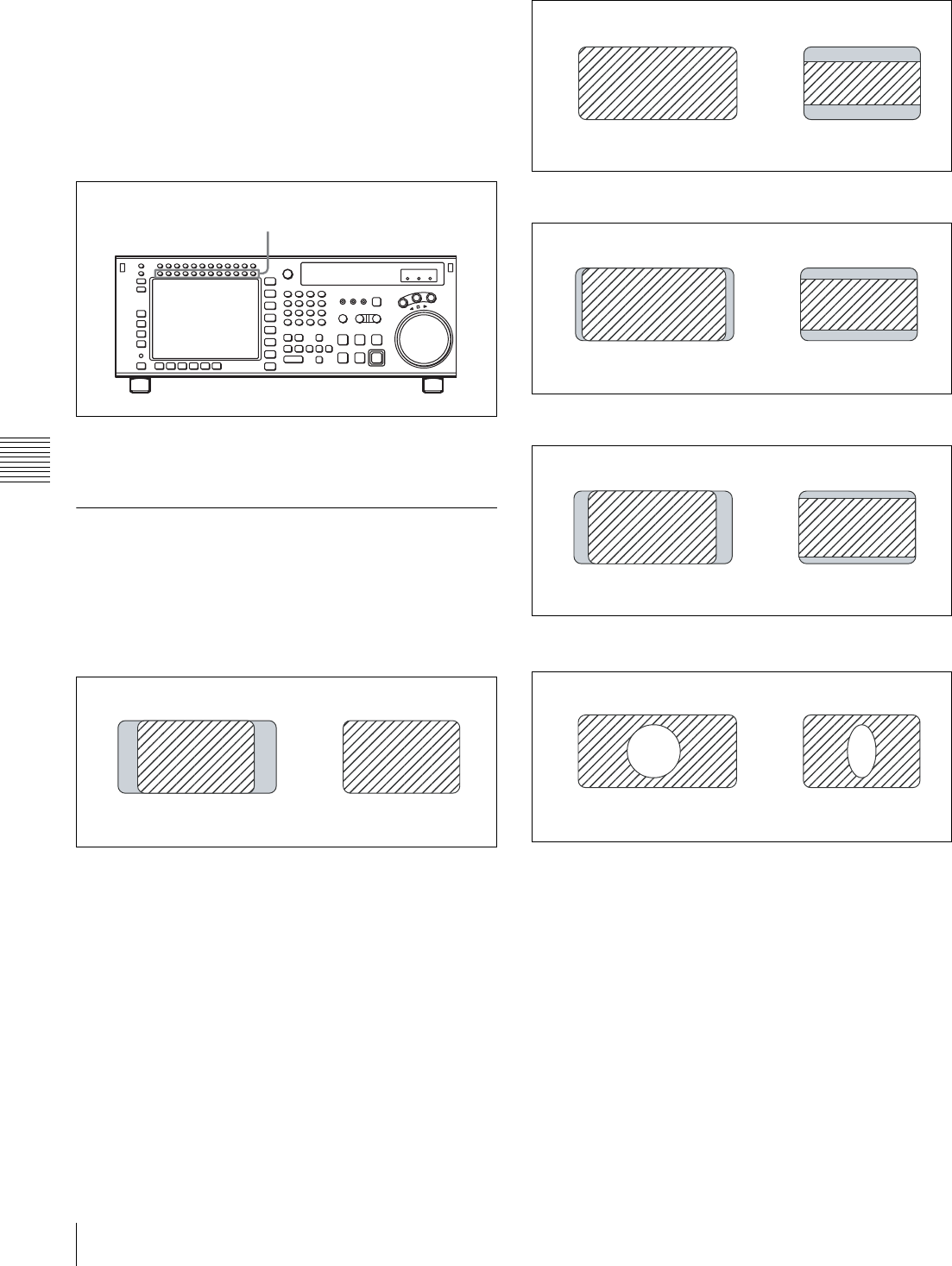
108 5-3 Preparing for Playback
Chapter 5 Recording/Playback
To adjust the audio playback level
manually
In the PB LEVEL adjustment mode, make the channel
active, then adjust to the desired volume with the MULTI
CONTROL knob or cursor R and r buttons. When you exit
the PB LEVEL adjustment mode, the vertical white line on
the right of the audio level meter and a horizontal white
line indicating the setting are displayed, indicating that the
playback level is subject to manual adjustment.
You can also carry out the playing level adjustment using
the VTR SETUP menu item 833 “AUDIO PB LEVEL”.
5-3-3 Selecting the HD-SD
Conversion Mode
Select the conversion mode using the VTR SETUP menu
item 930 “DOWNCONVERTER MODE”.
• Edge crop mode (CROP)
Horizontal adjustment of the edge cropping
Use the VTR SETUP menu item 932 “H CROP
POSITION (DC)”.
• Letter box mode (LETTER BOX)
When the letter box mode is selected, you can select one of
the following three conversion methods using the VTR
SETUP menu item 931 “LETTER BOX MODE (DC)”.
When 16:9 is selected
When 14:9 is selected
When 13:9 is selected
• Squeeze mode (SQUEEZE)
PB LEVEL adjustment
HD SD
n,
1/4 of the HDVS image on each side is cut off.
HD SD
,
The signal is compressed, maintaining an aspect ratio of 16:9.
HD SD
,
The sides of the HDVS image are cut and the signal is
compressed, changing the aspect ratio to 14:9.
HD SD
,
The sides of the HDVS image are cut and the signal is
compressed, changing the aspect ratio to 13:9.
HD SD
,
The 16:9 signal is compressed, changing the aspect ratio to 13:9.
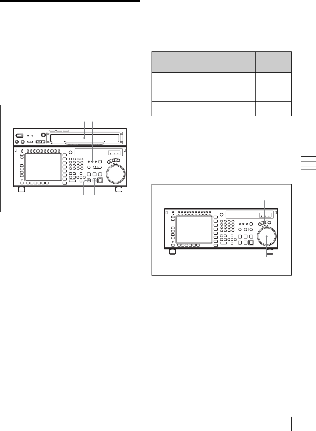
109
5-4 Playback
Chapter 5 Recording/Playback
5-4 Playback
There are four types of playback:
• Normal-speed playback
• Jog/Shuttle/Variable mode playback
• Capstan override playback
• DMC (Dynamic Motion Control) playback
5-4-1 Normal-Speed Playback
Follow the procedure below to play back at normal speed.
1
Insert a cassette.
For details on inserting a cassette, see “3-3-2
Inserting and Ejecting Cassettes” on page 34.
2
Press the PLAY button.
Playback starts and the SERVO indicator lights up to
indicate that the servo is locked.
3
Press the STOP button to stop playback.
If playback continues to the end of the tape
If the VTR SETUP menu item 407 “AUTO REWIND” is
set to “on”, then the tape automatically rewinds to the
beginning and stops.
5-4-2 Variable Speed Playback
In Jog/Shuttle/Variable modes, you can change the
playback speed as follows:
Jog mode: The playback speed corresponds to the
rotational speed of the search dial, ranging from –1 to
+1 or –2 to +2 times normal playback speed (for
Digital Betacam playback, ±3 times normal speed).
(The speed setting can be changed using the VTR
SETUP menu item 107 “JOG DIAL RESPONSE”.)
Shuttle mode: The playback speed corresponds to the
angle of rotation of the search dial. The playback
speed is different depending on the frame frequency
of the unit. The search dial clicks at the positions for
still-picture and ±10 times normal speed playback.
Variable mode: Playback speed is –1 times normal speed
when the search dial is rotated fully
counterclockwise, and +2 times normal speed (for
Digital Betacam playback, –1 to +3 times normal
speed) when rotated clockwise.
Jog mode playback
Follow the procedure below to play back in jog mode.
1
Press the JOG button, turning it on.
The VTR enters still-picture mode.
2
Rotate the search dial in the desired playback direction
and to the desired angle.
The tape is played back slowly, at a speed
corresponding to the rotational speed of the search
dial. A direction indicator (b or B) lights up to
indicate the direction of playback.
3
Stop rotating the search dial to stop jog mode
playback.
The indicator lights up.
1 2
32
Frame
frequency
Playback
speed
(HDCAM-SR)
Playback
speed
(HDCAM)
Playback
speed (D-
BETACAM)
23.98/24 Hz Ranging from
–50 to +50
Ranging from
–60 to +60
25 Hz Ranging from
–48 to +48
Ranging from
–58 to +58
Ranging from
–58 to +58
29.97/30 Hz Ranging from
–40 to +40
Ranging from
–50 to +50
Ranging from
–50 to +50
1,2,3
1
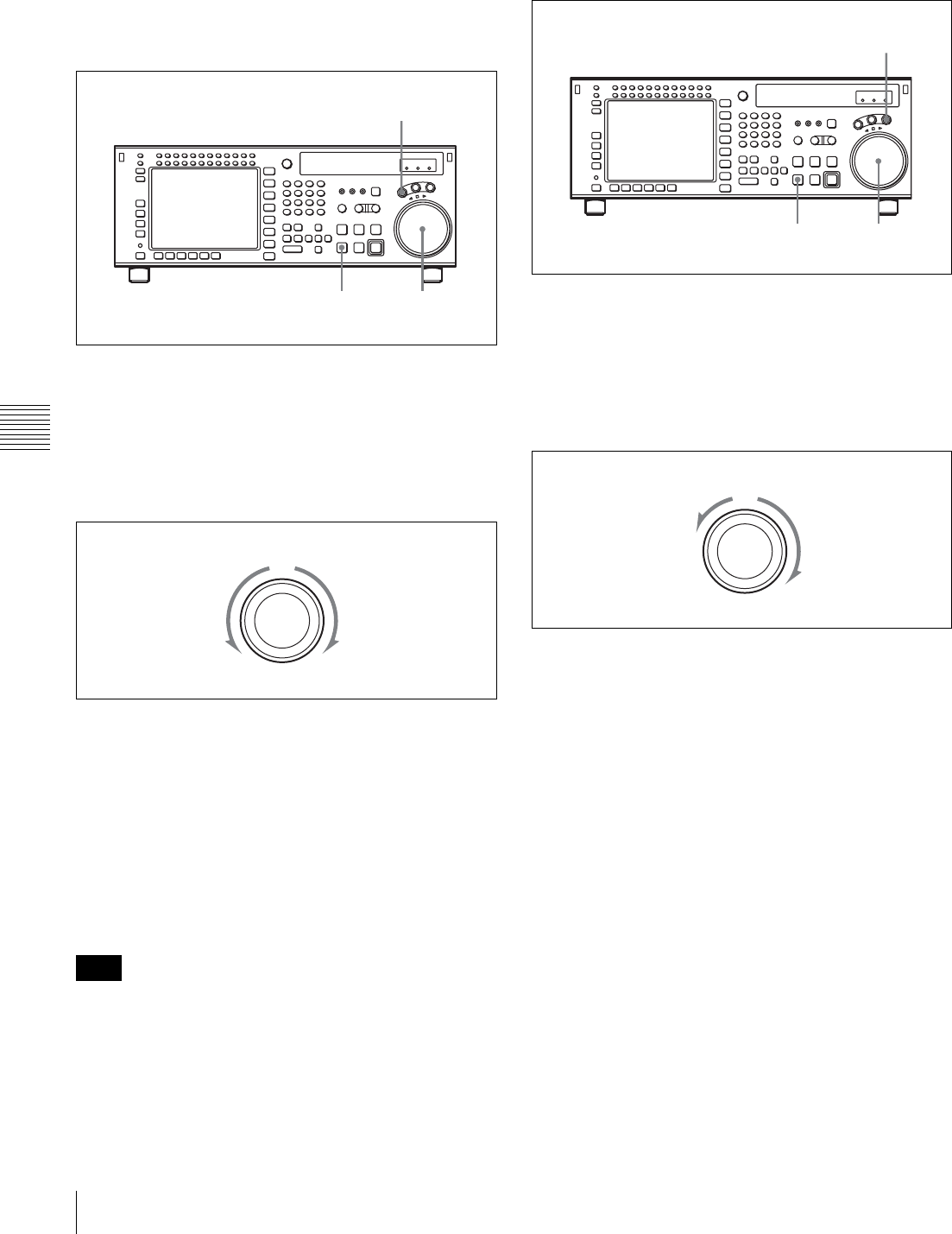
110 5-4 Playback
Chapter 5 Recording/Playback
For details on switching the search dial functions, refer to
the Maintenance Manual Volume 1.
Shuttle mode playback
Follow the procedure below to play back in shuttle mode.
1
Press the SHUTTLE button, turning it on.
The VTR enters still-picture mode.
2
Rotate the search dial in the desired playback direction
and set the angle of rotation as required to obtain the
desired playback speed.
The tape is played back at a speed that corresponds to
the angle of the search dial. A direction indicator (b or
B) lights up to indicate the direction of playback.
The search dial clicks at the positions for still-picture
and ±10 times normal-speed playback.
3
Set the search dial to center position for still-picture, or
press the STOP button to stop shuttle mode playback.
To return to normal-speed playback
Press the PLAY button.
The audio signal output status is specified by the following
settings of the VTR SETUP menu item 017 “PB/EE
SELECT MENU”.
EE: The input audio is always output.
MU: The audio output is always muted.
PB: The playback signal is always output.
Variable mode playback
Follow the procedure below to play back in variable mode.
1
Press the VAR button, turning it on.
The VTR enters VAR mode.
2
Rotate the search dial in the desired playback direction
and set the angle of rotation as required to obtain the
desired playback speed.
The tape is played back at a speed that corresponds to
the angle of the search dial. A direction indicator (b or
B) lights up to indicate the direction of playback.
The search dial clicks at the positions for still-picture
and normal-speed playback.
3
Set the search dial to center position for still-picture, or
press the STOP button to stop variable mode playback.
To return to normal-speed playback
Press the PLAY button.
To alternate between normal-speed playback and
variable mode playback
After you have set the search dial to the angle that
corresponds to the desired playback speed, pressing the
PLAY button or VAR button selects normal-speed
playback or variable mode playback, respectively.
To stop or start variable mode playback, press the STOP
button or VAR button, respectively.
The VTR is factory set so that pressing the JOG,
SHUTTLE, or VAR button is required in order to enter
variable-speed playback mode. To change this setting, use
Note
1,2,33
1
(
REV
)(
F.FWD
)
Shuttle mode
2,33
1
–1
+2
Variable mode
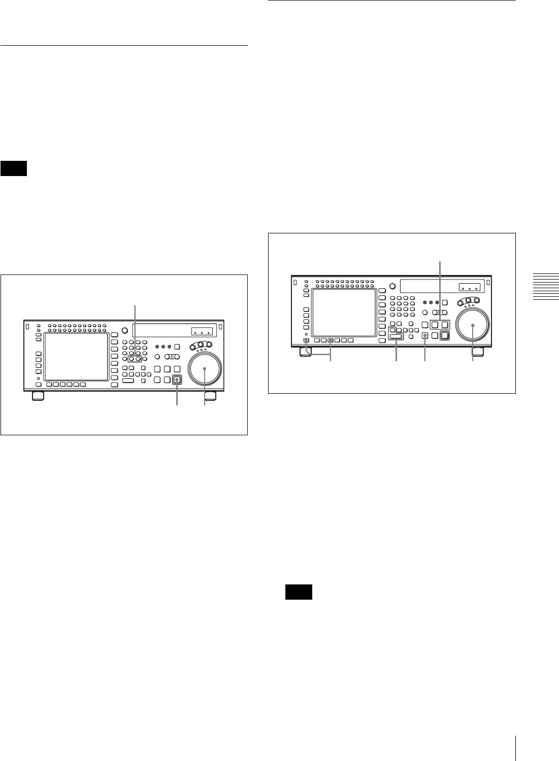
111
5-4 Playback
Chapter 5 Recording/Playback
the VTR SETUP menu item 101 “SELECTION FOR
SEARCH DIAL ENABLE”.
5-4-3 Capstan Override Playback
When playing back the same program on two VTRs, you
can adjust the playback phases of the two VTRs so that
they are synchronized.
There are two ways to make this adjustment:
(A) Using the search dial
(B) Using the +/– buttons
When using method (A), change the system setup so that
jog/shuttle mode playback is inhibited even when the
search dial is rotated. Doing so prevents the VTR from
accidentally entering jog/shuttle mode during capstan
override playback.
Set the VTR SETUP menu item 101 “SELECTION FOR
SEARCH DIAL ENABLE” to “via search key”.
1
Use either method (A) or (B).
(A) Rotate the search dial while holding down the
PLAY button to adjust the playback speed.
The adjustment range is ±15% (in steps of 1%) of
the normal playback speed.
(B) Press the + or – button while holding down the
PLAY button to adjust the playback speed.
Every time the + or – button is pressed, the speed
changes by 1 frame.
During playback at increased or decreased speed, the
SERVO indicator goes off since the servo is not locked
(capstan override).
2
Release the PLAY button after you have finished
adjusting the phase.
The VTR returns to normal-speed playback and the
SERVO indicator lights up.
5-4-4 DMC Playback
Overview of DMC playback
DMC (Dynamic Motion Control) playback allows you to
vary the playback speed in variable mode (in the DT
playback range from –1 to +2 times normal speed) for
certain sections of the tape, then store the specified speed
in memory for later playback.
For example, during a live broadcast of a sporting event,
you can set the start and end points of important scenes
while recording, and immediately play back and broadcast
those scenes using DMC playback.
Storing playback speeds in memory
Follow the procedure below to store DMC playback
speeds in memory.
1
In the HOME menu, press the ALT/[F7] (DMC)
buttons to light up DMC on the display.
2
Set a start point during recording or on a previously
recorded tape by simultaneously pressing the ENTRY
button and the IN button.
3
Press the STOP button to enter stop mode.
4
Rotate the search dial to select the initial playback
speed.
The selected speeds are shown in the time data display
window in the menu display.
If the VTR SETUP menu item 101 “SELECTION
FOR SEARCH DIAL ENABLE” is set to “dial
direct”, initial speed settings cannot be made. Change
the setting of this menu item to “via search key”.
5
Press the PREROLL button and PREVIEW/REVIEW
button simultaneously.
Note
1(A)1,2
1(B)
Note
2 4,63,7
5
1
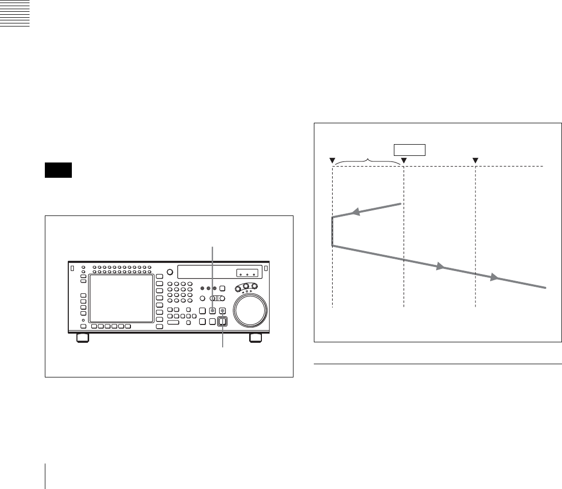
112 5-4 Playback
Chapter 5 Recording/Playback
The tape is prerolled and played back at the initial
speed from the preroll point to the speed variation start
point. The moment the tape passes the speed variation
start point, the MEMORY indicator in the display
starts flashing.
(The x indicator appears in the time data display
window, indicating that tape speed memorization in
DMC mode is active.)
6
Rotate the search dial to the position for the desired
playback speed.
The speed variation is stored in memory while the
MEMORY indicator is flashing.
7
Press the STOP button to stop the tape.
If the MEMORY indicator flashes before the tape
reaches the speed variation end point
Memory has been exceeded and the VTR cannot store any
more data for playback speed variations.
Notes on the x indicator and the MEMORY
indicator
The x indicator shows that the tape speed memorization in
DMC mode is taking place.
The MEMORY indicator flashes during playback speed
memorization, and goes out when memorization of the
playback speed has been completed.
Performing DMC playback
There are two methods of starting DMC playback.
• Starting playback at the on-air cue from the on-air start
point
• Starting playback immediately after prerolling
To avoid operation errors, we recommend that you use the
VTR alone when performing DMC playback.
To start playback at the on-air cue from the on-air
start point
1
Press the PREROLL button, turning it on.
The tape is cued up to the on-air start point.
2
Press the PREVIEW/REVIEW button at the moment
the on-air cue is given.
The PREVIEW/REVIEW button lights up. When the
tape passes the speed variation start point, DMC
playback starts and continues at the speed(s) stored in
memory.
When the tape passes the speed variation end point,
normal-speed playback starts.
To start playback immediately after prerolling
Press the PREVIEW/REVIEW button.
The PREVIEW/REVIEW button lights up. When the tape
passes the speed variation start point, DMC playback starts
and continues at the speed(s) stored in memory. When the
tape passes the speed variation end point, normal-speed
playback resumes.
To stop the tape during DMC playback
Press the STOP button.
To exit DMC playback mode
Press the ALT/[F7] (DMC) buttons in the HOME menu to
turn off the DMC indicator.
During DMC playback, the tape runs as shown in the
diagram below.
5-4-5 Playing Back Non-audio Data
Non-audio data recorded on a tape is detected
automatically and played back.
Note
2
1
Preroll time ×
initial speed
Speed variation
end point
Tape runs at
initial speed
Playback at
normal speed
Playback at the
memorized speeds
IN point

113
5-4 Playback
Chapter 5 Recording/Playback
When non-audio data is being played back:
• Below the input display in the audio level meter section,
the DATA mark lights in white.
• For the audio level meters, all regions light.
• The analog audio outputs (main line/monitor/
headphones) are muted.
• The audio output level can be adjusted during non-audio
data playback, but output non-audio data is not affected.
5-4-6 Performing Program Play
Overview
When using HDCAM-SR tapes, you can play them over
the range ±5.0% of normal speed. This is called program
play.
During program play you can correct the pitch of audio
signals.
The program play function is available only when all of the
following conditions are met.
• Combination of SRW-5000/5500 and HKSR-5001 serial
numbers:
SRW-5000/5500: Serial No. 12001 or higher
HKSR-5001: Serial No. 11001 or higher
• Tape format: HDCAM-SR
• System frequency: 4:2:2/1080/59.94i or 720/59.94P. No
audio is output when playing tapes recorded at other
system frequencies.
• Note about editing: Always use time code to check and
set edit points when editing while performing program
play on the player. Precise editing operations cannot be
guaranteed if you use CTL signals.
To execute program play
Proceed as follows to execute program play.
1
Set the same system setting for the VTR main unit and
for FC output.
HD SDI signals will be output from both the HD SDI
OUTPUT connectors and the FC OUT connectors.
2
Set VTR SETUP menu item 020 “P PLAY” to “on”.
3
Press the HOME button.
The HOME menu appears.
4
Turn the MULTI CONTROL knob to set the program
play speed.
5
Press the PLAY button and VAR button at the same
time.
Program play starts at the specified speed.
During program play, HD SDI signals are output from
the FC OUT connectors only. They are not output
from the HD SDI OUTPUT connectors.
About audio pitch correction
Some menu settings are required to enable audio pitch
correction during program play.
When audio pitch correction is enabled, it is also carried
out at times other than during program play, whenever an
HDCAM-SR tape is played that has a system setting
(frame frequency) that is different from the current system
setting. However, the difference between system settings
must be within ±5%, as shown below.
23.98 frames y 24 frames
23.98/24 frames y 25 frames
29.97 frames y 30 frames
To enable pitch correction
Set VTR SETUP menu item 816 “PITCH
CORRECTION” to “on”.
Pitch correction group settings
You can use VTR SETUP menu item 817 “PITCH
CORRECTION GROUP select” to assign the 12 audio
channels to groups.
You can assign up to 6 channels to 1 group. Pitch
correction is performed at the same time for all channels in
a group, so phase differences do not arise. However, phase
differences may arise between different groups.
Pitch correction detection mode settings
You can use VTR SETUP menu item 818 “PITCH
CORRECTION DETECT MODE select” to specify the
detection mode for each pitch correction group.
Mode1: Search for zero-cross points in the audio data, and
connect the zero-cross points.
Note
Note
34
5
Note

114 5-4 Playback
Chapter 5 Recording/Playback
Mode2: Search for zero-cross points in the same way as
Mode1, but connect zero-cross points only when low-
level samples are detected around the zero-cross
points.
Mode3: At a regular interval corresponding to the
playback speed, connect the audio data before and
after the processing target with a cross fade.
OFF: Output audio data by performing rate conversion
processing. This changes the frequency
characteristics and pitch according to the specified
program play speed.
Cross fade processing may be performed if zero-cross
points cannot be detected in Mode1 or Mode2 processing.
Note

115
6-1 Basic Automatic Editing
Chapter
Chapter 6 Editing
6
Editing
6-1 Basic Automatic
Editing
6-1-1 Overview of Automatic
Editing
Automatic edit modes
The VTR provides the following two modes for automatic
editing:
Assemble mode
New scenes are added to the end of previously recorded
scenes.
CTL signals, time codes, video and audio signals on tape
in the player are recorded onto tape in the recorder VTR.
Insert mode
New scenes are inserted between previously recorded
scenes.
CTL signals on tape in the recorder VTR are not
overwritten. Video, digital audio, and time code signals
can be recorded separately.
Both of these two edit modes support DMC editing. In
insert mode, you can also use split editing.
Interpolation of time codes by the CTL counter
To use time codes as addresses of edit points, the time
codes must be recorded on the tape in ascending order.
As long as they are in ascending order, time codes do not
have to be continuous. The CTL counter automatically
interpolates data for editing even if there are breaks in the
continuity in the time codes.
Steps in automatic editing
The sequence of steps that are taken to do automatic
editing with two VTRs is as follows:
Select the edit mode (see page 117).
m
Set edit points for the recorder and player VTR
(see page 117).
m
Preview the edit section (see page 121).
m
Perform the edit (see page 124).
m
Confirm and modify the edit points
(see pages 120 and 122).
m
Confirm the results of the edit (see page 125).
Editing precautions
Using an editing control unit
When using an editing control unit to control the VTR, set
the edit delay on the control unit so that CUT-IN and CUT-
OUT commands are sent to the VTR five frames ahead of
the actual edit point.
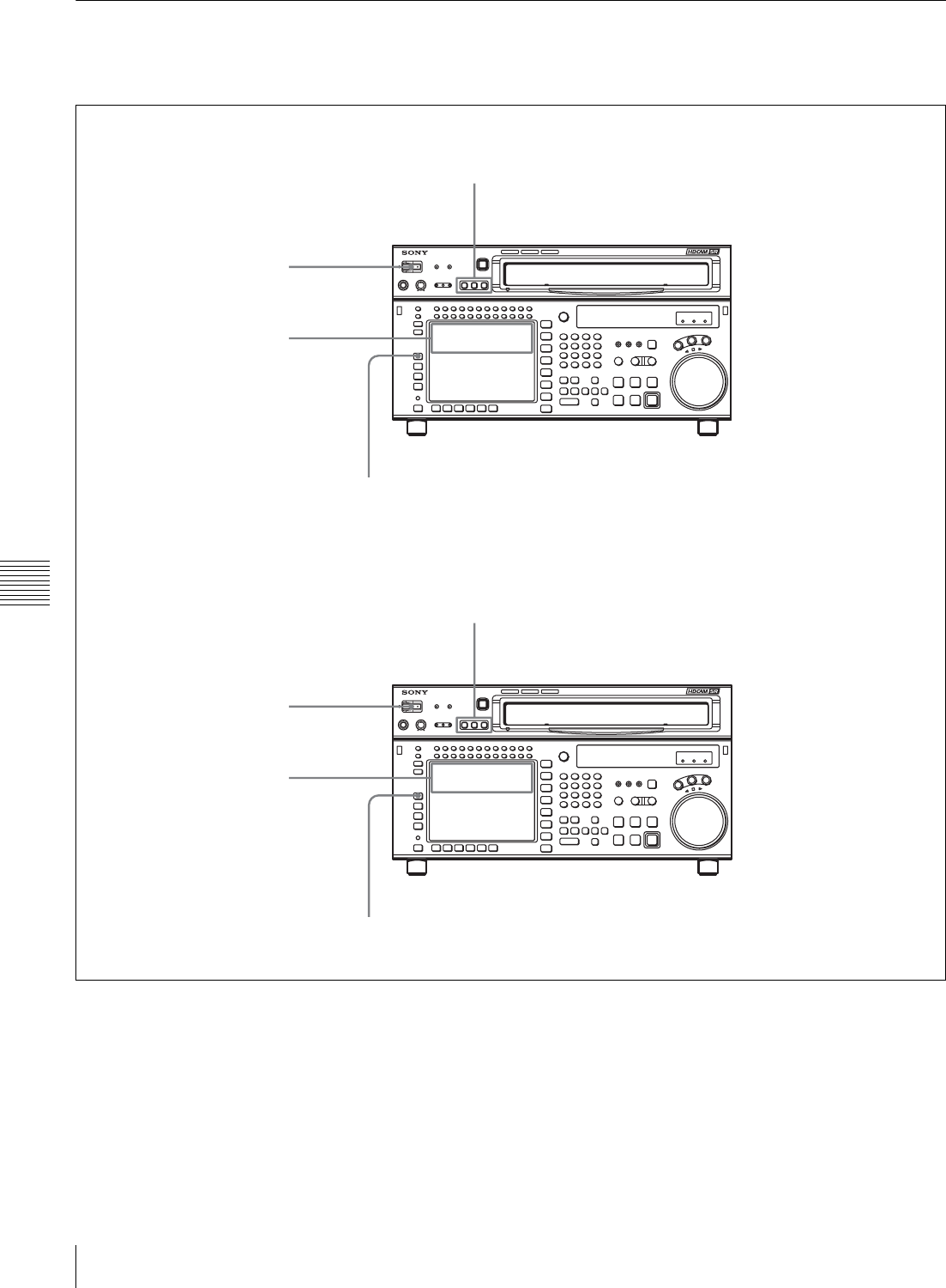
116 6-1 Basic Automatic Editing
Chapter 6 Editing
6-1-2 Setting Switches and Menus
Before editing, set the following switches and menus as
shown below.
SRW-5000
HD DIGITAL VIDEO CASSETTE RECORDER
SRW-5000
HD DIGITAL VIDEO CASSETTE RECORDER
[F1] (TIMER SEL) button in the TC menu: TC or CTL
REMOTE buttons: None of these buttons light up.
Player VTR
POWER switch: ON
Recording level indication:
recording levels
REMOTE buttons: 1(9P) button lights up.
[F1] (TIMER SEL) button in the TC menu: TC or CTL
POWER switch: ON
Playback level indication:
playback levels
Recorder VTR
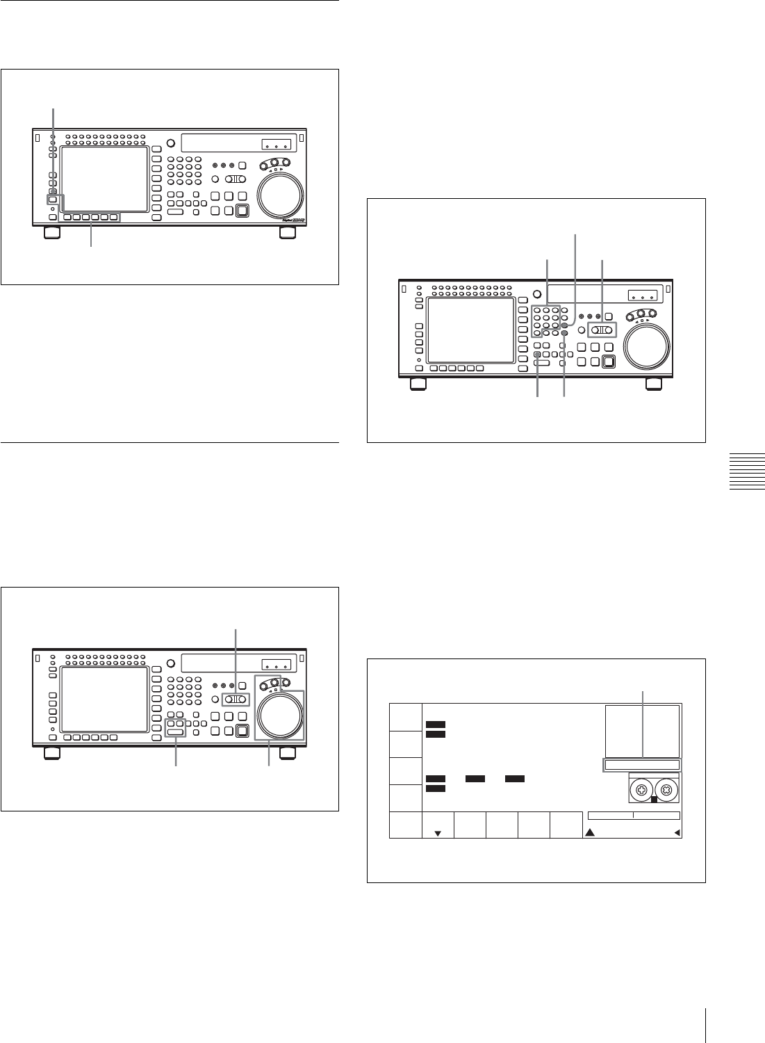
117
6-1 Basic Automatic Editing
Chapter 6 Editing
6-1-3 Selecting the Edit Mode
Select assemble or insert mode.
Press one of the following buttons to select the respective
edit mode:
•Assemble mode: [F3] (ASSEMBLE) button in the
HOME menu
•Insert mode: the appropriate INSERT button in the
HOME menu, [F4] (INS TC), [F5] (INS VIDEO), [F6]
(INS AUDIO)
6-1-4 Setting Edit Points
This section describes how to set edit points (IN and OUT
points). In insert mode, a technique called split editing
allows you to set edit points separately for video and audio.
Positioning and setting edit points
1
Press the RECORDER or PLAYER button to select
the VTR for which edit points are to be set.
The button lights up.
2
Rotate the search dial in jog or shuttle mode to position
the edit point.
For details on jog or shuttle playback, see “5-4-2
Variable Speed Playback” on page 109.
3
Press the IN (or OUT) button while holding down the
ENTRY button.
The time data for the IN (or OUT) point appears in the
menu display.
4
Repeat steps 1 to 3 to set the remaining edit points.
Setting edit points with the numeric buttons
1
Press the RECORDER or PLAYER button to select
the VTR for which edit points are to be set.
The button lights up.
2
Enter the edit point data with the numeric buttons.
For example, to enter 01H00M30S00F, press 1, 0, 0, 3,
0, 0, 0. (You need not input leading zeros. If the
entered value consists of less than eight digits, the
leading digit(s) is (are) set to zero(s) when you press
the SET button.)
To delete entered data
Press the CLR button.
[F3] (ASSEMBLE) button in the HOME menu
[F4] (INS TC) to [F6] (INS AUDIO) buttons in the HOME
menu
32
1
1
34
2
CLR button
PB/EE
PB
RECINH
off
ASSEM-
BLE
off
INS
TC
off STILL HDCAM-SR
REMAIN:01H06M
! ALT+TC
PLAY LOCK
01
H
04
M
58
S
00
F
01
H
04
M
58
S
00
F
AIN 00:01:10:00 AOUT 00:02:10:00
IN 00:01:10:00 OUT 00:02:10:00
INS
VIDEO
off
INS
AUDIO
INTRP DF F2
INTRP DF 2FO F2
LTC
TCR
LTC
TCR
SS
Data entry window
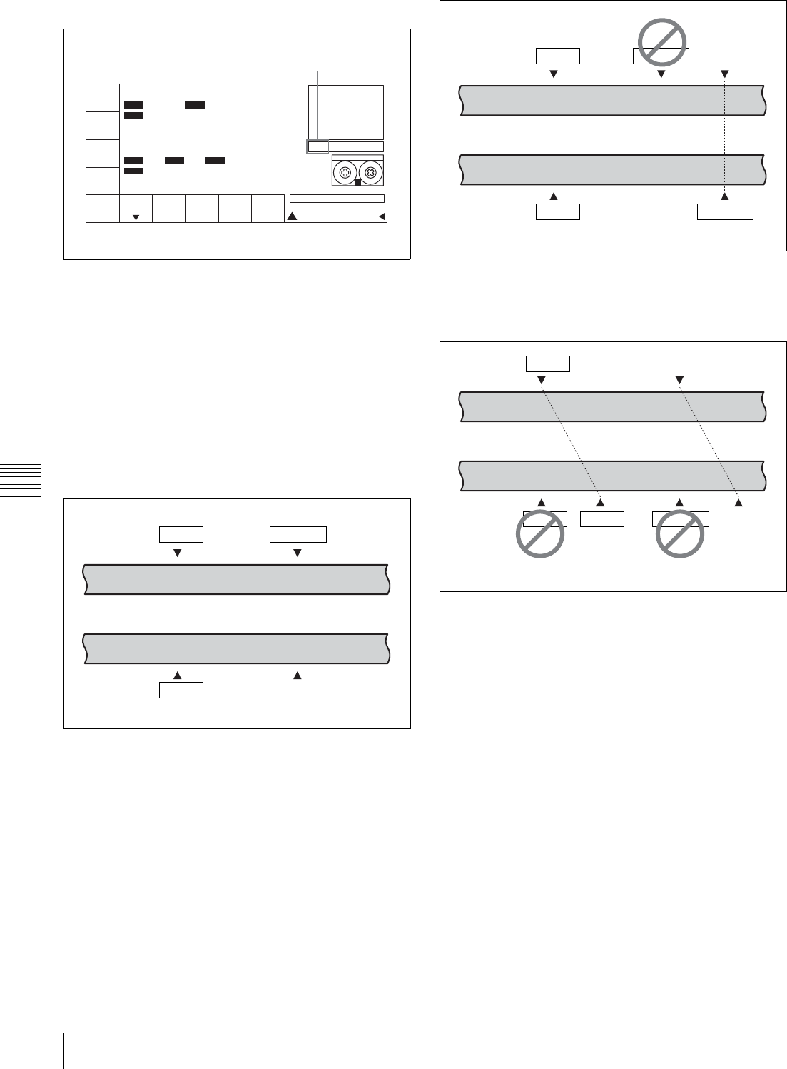
118 6-1 Basic Automatic Editing
Chapter 6 Editing
3
Press the SET button to set the input data.
4
Press the IN (or OUT) button.
The time data for the IN (or OUT) point appears in the
menu display.
About automatic edit point setting
Editing requires a total of four edit points: IN and OUT
points for both the recorder and player VTRs. However, as
soon as you set three edit points, the VTR automatically
sets the fourth point.
In the figure below, the points enclosed in a box have been
set manually, while the OUT point for the player VTR has
been set automatically.
Whether set manually or automatically, all edit points can
be changed or deleted at any time.
Automatic setting of OUT points
When the fourth edit point (OUT point) is set, the edit
point data is activated and the invalid point is
automatically deleted.
Automatic setting of IN points
When an IN point is corrected, the OUT point is set
automatically using the duration of the VTR whose edit
points were not changed.
Split editing
Positioning and setting edit points
Split editing allows you to set edit points separately for
video and audio. Set audio edit points with the AUDIO IN/
OUT buttons and video edit points with the IN/OUT
buttons.
Split editing, however, can only be done when the recorder
VTR is in insert mode.
PB/EE
PB
RECINH
off
ASSEM-
BLE
off
INS
TC
off STILL HDCAM-SR
REMAIN:01H06M
! ALT+TC
SET 01 00 30 00
PLAY LOCK
01H04M58S00F
01H04M58S00F
AIN 00:01:10:00 AOUT 00:02:10:00
IN 00:01:10:00 OUT 00:02:10:00
INS
VIDEO
off
INS
AUDIO
INTRP DF F2
INTRP DF 2FO F2
LTC
TCR
2FD
LTC
TCR
SS
SET is displayed.
Recorder VTR
Player VTR
IN point OUT point
IN point OUT point
OUT point
Recorder VTR
OUT point
Player VTR
Automatically
set edit point
Fourth edit point
IN point
IN point OUT point
OUT pointIN point
Recorder VTR
OUT point
Player VTR
Automatically
set edit point
OUT point
Corrected
edit point
IN point
IN point
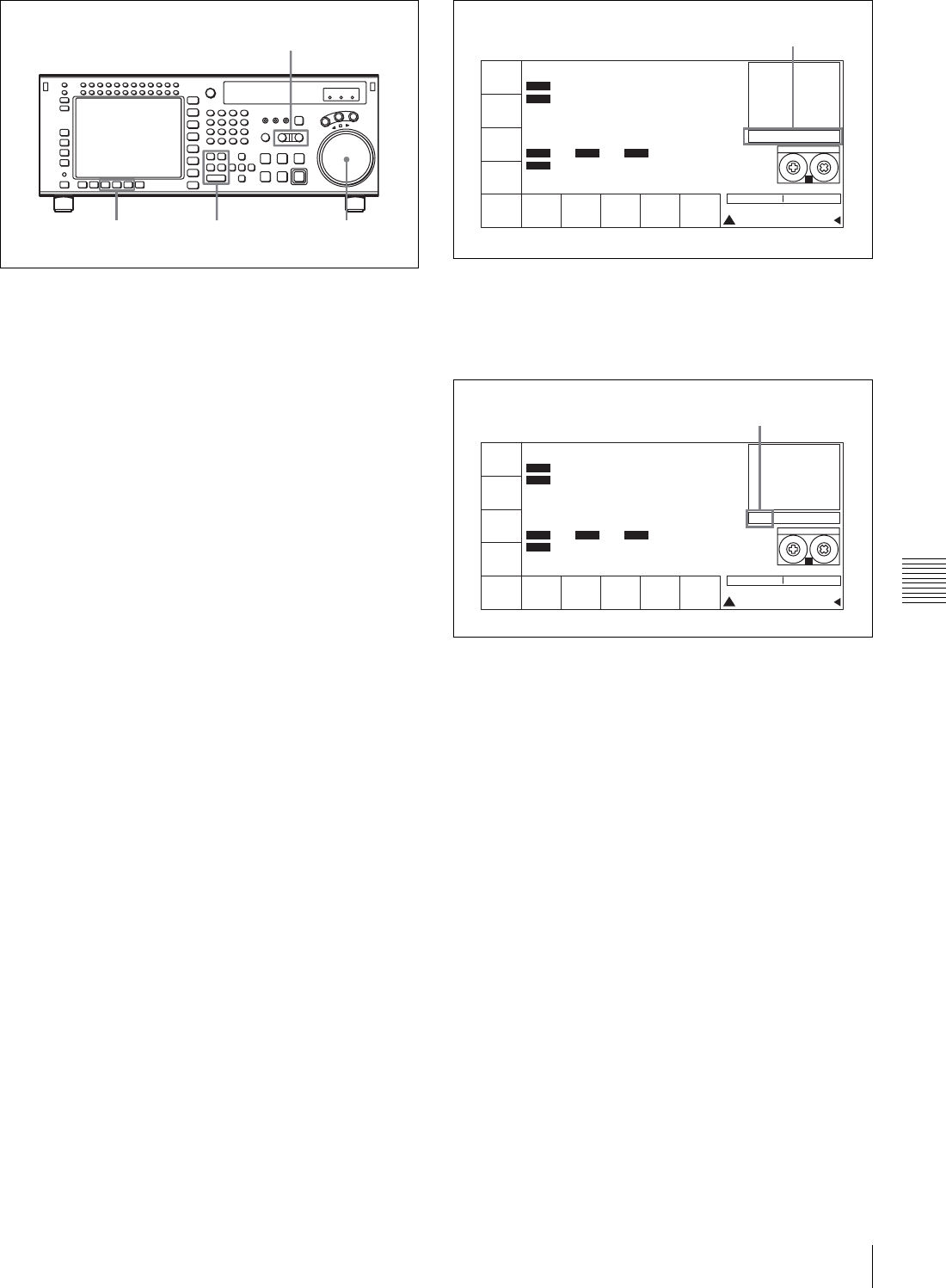
119
6-1 Basic Automatic Editing
Chapter 6 Editing
1
Press the appropriate INSERT button ([F4] (INS TC),
[F5] (INS VIDEO), [F6] (INS AUDIO)).
2
Press the RECORDER or PLAYER button to select
the VTR for which edit points are to be set.
The button lights up.
3
To locate the edit points, rotate the search dial in jog or
shuttle mode.
For details on jog/shuttle playback modes, see “5-4-2
Variable Speed Playback” on page 109.
4
Press one of the IN, OUT, AUDIO IN or AUDIO OUT
button while holding down the ENTRY button.
5
Repeat steps 2 to 4 to set the remaining edit points.
Setting an edit point with the numeric buttons
1
Press the desired INSERT button ([F4] (INS TC), [F5]
(INS VIDEO), [F6] (INS AUDIO)).
2
Press the RECORDER button or PLAYER button, to
select the VTR on which you will set the edit point.
The button you pressed lights.
3
With the numeric buttons, enter data into the data entry
window.
For example, to enter 01H00M30S00F, press 1, 0, 0, 3,
0, 0, 0. (You need not input leading zeros. If the
entered value consists of less than eight digits, the
leading digit(s) is (are) set to zero(s) when you press
the SET button.)
To delete entered data
Press the CLR button.
4
Press the SET button to confirm the input data.
5
Press any of the IN, OUT, AUDIO IN, and AUDIO
OUT buttons.
When the edit point is set, it appears on the editing data
display.
About automatic split edit point setting
Split editing requires a total of eight edit points: four edit
points for video editing (IN and OUT points for both the
recorder and player VTRs) and four edit points for audio
editing (AUDIO IN and OUT points for both the recorder
and player VTRs). However, as soon as you set five edit
points, the VTR automatically sets the remaining three
points. For example, if you set three edit points for video
(or audio) and two for audio (or video), the remaining three
points are automatically set, regardless of whether these
points are for the recorder or player.
In the following example, the points enclosed in a box
have been set manually and the AUDIO OUT point for the
recorder VTR, and the AUDIO IN and OUT points for the
player VTR have been set automatically.
Note that whether set manually or automatically, all edit
points can be changed or deleted at any time.
43
2
1
PB/EE
PB
RECINH
off
ASSEM-
BLE
off
INS
TC
off
INS
VIDEO
off
INS
A-CH2
off
INS
A-CH3
off
INS
A-CH4
off
INS
CUE
off
INS
A-CH1
off
STILL
! ALT+TC
01H04M58S00F
01H04M58S00F
AIN 00:01:10:00 AOUT 00:02:10:00
IN 00:01:10:00 OUT 00:02:10:00
INTRP DF F2
INTRP DF 2FO F2
LTC
TCR
LTC
TCR
HDCAM-SR
REMAIN:01H06M
PLAY LOCK
SS
Data entry window
PB/EE
PB
RECINH
off
ASSEM-
BLE
off
INS
TC
off
INS
VIDEO
off
INS
A-CH2
off
INS
A-CH3
off
INS
A-CH4
off
INS
CUE
off
INS
A-CH1
off
STILL
! ALT+TC
SET 01 00 30 00
01
H
04
M
58
S
00
F
01
H
04
M
58
S
00
F
AIN 00:01:10:00 AOUT 00:02:10:00
IN 00:01:10:00 OUT 00:02:10:00
INTRP DF F2
INTRP DF 2FO F2
LTC
TCR
LTC
TCR
HDCAM-SR
REMAIN:01H06M
SS
PLAY LOCK
SET is displayed.
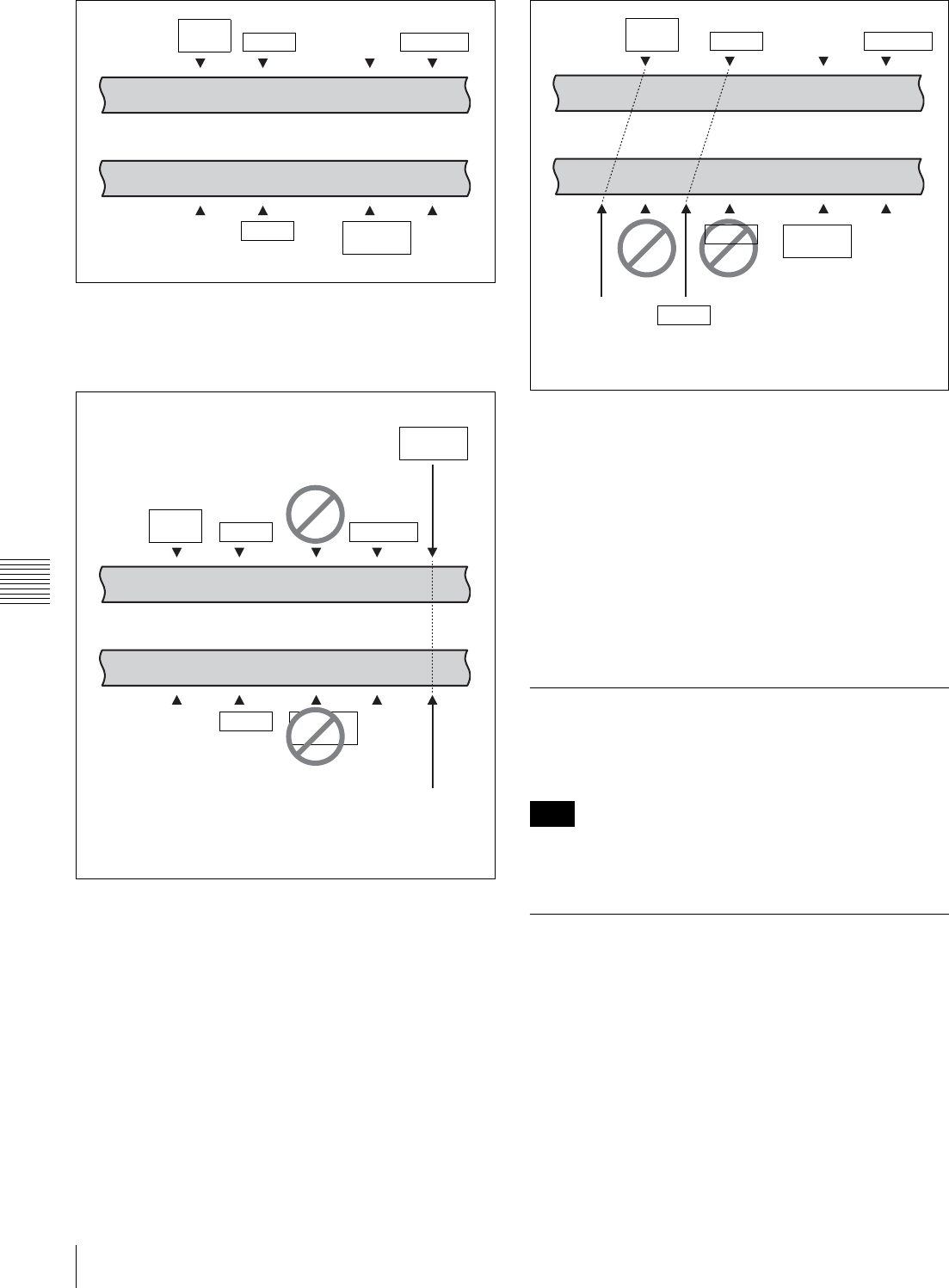
120 6-1 Basic Automatic Editing
Chapter 6 Editing
Automatic setting of AUDIO OUT points
When the sixth edit point (AUDIO OUT point) is set, the
edit point data is activated and the invalid AUDIO OUT
points are automatically deleted.
Automatic setting of edit points by correcting IN
points
When IN points are corrected, the duration in the
uncorrected VTR is used to automatically set OUT points
and AUDIO IN/OUT points.
You can use the VTR SETUP menu to select an audio edit
mode from among cut, cross-fade, and fade-in/out, and set
the duration of the selected edit.
For details, see the menu items in the 300 range in the VTR
SETUP menu.
Using a VTR without the split editing function
If the player VTR does not support the separate setting of
edit points for video and audio, you can set AUDIO IN and
AUDIO OUT points on the recorder and three video edit
points to enable split editing.
6-1-5 Editing Non-audio Data
Before editing non-audio data, set the VTR SETUP menu
item 317 “AUDIO EDIT MODE” to “cut edit”.
Noise may be produced during editing of certain non-audio
data.
6-1-6 Confirming Edit Points
Displaying the duration between two edit
points
The following six kinds of duration can be displayed in the
time data display window:
• Between IN and OUT points
• Between IN and AUDIO OUT points
• Between IN and AUDIO IN points
• Between OUT and AUDIO OUT points
• Between OUT and AUDIO IN points
AUDIO
IN point
Recorder VTR
Player VTR
OUT point
AUDIO
OUT point
IN point OUT point
AUDIO
IN point
IN point AUDIO
OUT point
AUDIO
OUT
point
AUDIO
OUT point
AUDIO
IN point
Recorder VTR
Player VTR
OUT point
AUDIO
IN point
AUDIO
OUT point
Edit point set
automatically
Sixth edit point set
AUDIO
OUT point
IN point
IN point
OUT point
Note
Recorder VTR
Player VTR
AUDIO
IN point
OUT point
AUDIO
IN point
AUDIO
OUT point
IN point
IN point
OUT point
AUDIO
OUT point
AUDIO
IN point IN point
AUDIO
IN point IN point
Automatically
set edit point
Corrected
IN point
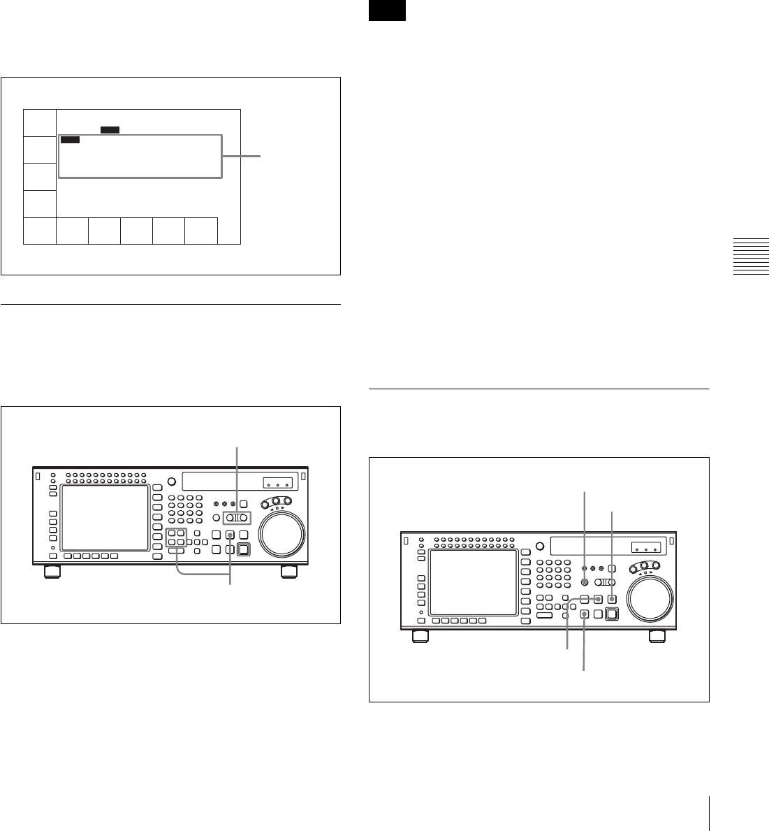
121
6-1 Basic Automatic Editing
Chapter 6 Editing
• Between AUDIO IN and AUDIO OUT points
Durations are calculated as follows.
• If both IN and OUT points are set, the duration is the
time between the points.
• If one of the edit points is not set, the duration is set to
00:00:00.
1
Press the RECORDER or PLAYER button to select
the VTR for which you want to confirm a duration.
The button lights up.
2
Hold down any two IN, OUT, AUDIO IN, or AUDIO
OUT buttons.
The duration between the points corresponding to the
two buttons is displayed. The value can be negative.
6-1-7 Cuing Up and Prerolling
You can preroll the tape to a point prior to the edit start
point, or cue up the tape to any edit point.
Follow the procedure below to cue up or preroll the tape.
1
Press the RECORDER or PLAYER button to select
the VTR which you want to operate.
The button lights up.
2
To cue up the tape to an edit point
Press one of the IN, OUT, AUDIO IN, or AUDIO
OUT button while holding down the PREROLL
button.
The tape moves to the edit point corresponding to the
button, then stops.
To preroll the tape
Press the PREROLL button.
The tape is rewound to a point before the edit start
point by the amount determined by the preroll time
setting.
When the [F1] (TIMER SEL) button in the TC menu is set
to CTL mode, cuing up is slightly slower than in TC mode.
This is to maintain the accuracy of the CTL signals.
You can set up the VTR so that priority is placed on cuing
accuracy or speed. Change the setting of the VTR SETUP
menu item 403 “CUEUP BY TC” and menu item 404
“CUEUP BY CTL”.
Changing the preroll time
The preroll time is factory set to 5 seconds, but can be set
to any time between 0 and 30 seconds, in 1-second steps.
For details, see “4-2-6 Setting the Preroll Time
(PREROLL TIME)” on page 52.
When changing the preroll time, set it so that the recorded
section prior to the edit start point is longer than the preroll
time.
The preroll time used in automatic editing is the preroll
time set for the recorder.
6-1-8 Previewing
Follow the procedure below to preview the edit.
To preview the edit, press the AUTO button to switch to
AUTO mode, then press the PREVIEW/REVIEW button.
TIMER
SEL
TC
DUR
DF
PLAY LOCK
TIMER
RESET
TIMER
SET
TIMER
HOLD
off
TCR
SEL
VITC
TCG
MODE
prst
RUN
MODE
rec
DF/NDF
df
TC2
SEL
REGENE
SOURCE
int
0H01M00S00F
AIN 00:01:10:00 AOUT 00:02:10:00
IN 00:01:10:00 OUT 00:02:10:00
Duration
between two
edit points
2
1
Note
AUTO button PREVIEW/REVIEW
button
STOP button
PREROLL button
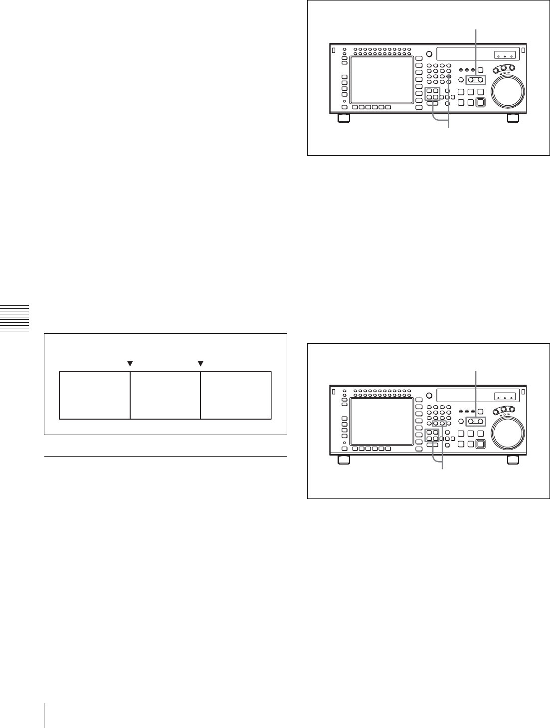
122 6-1 Basic Automatic Editing
Chapter 6 Editing
During previewing, the PREVIEW/REVIEW button lights
up.
After previewing, correct the edit points as required, then
do the preview again.
For details on modifying edit points, see “6-1-9 Modifying
Edit Points” on page 122.
To stop previewing
Press the STOP button.
The tape stops immediately.
To rewind the tape to the preroll point
Press the PREROLL button.
To rewind the tape to the edit point
Press the PREROLL button together with the button
corresponding to the edit point.
Monitoring signals during previewing
During previewing, you can monitor the following video
and audio signals on a monitor connected to the recorder
VTR:
• Between preroll and IN points: Playback signal of the
recorder VTR can be monitored.
• Between IN and OUT points: Playback signal of the
player VTR can be monitored in E-E mode.
• Between OUT and post-roll points: Playback signal of
the recorder VTR can be monitored.
This may be illustrated as shown below:
6-1-9 Modifying Edit Points
If an edit point is incorrectly set, for example, if an OUT
point is located before an IN point, or the length of an edit
section is different for the recorder and player VTRs, the
time data for the incorrectly set edit point flash indicating
that the VTR cannot perform editing or previewing. In this
case, delete the edit point, then set a new one correctly.
You can also move an edit point position in one-frame
units.
Deleting edit points
1
Press the RECORDER or PLAYER button to select
the VTR on which to perform the edit point deletion.
The button lights up.
2
Press one of the IN, OUT, AUDIO IN or AUDIO OUT
button while holding down the CLR button to delete
the corresponding edit point.
The edit point is deleted and --:--:--:-- appears in the
time data display.
Moving an edit point position by one frame
at a time
1
Press the RECORDER or PLAYER button to select
the VTR on which to modify the edit point.
The button lights up.
2
Press the + or – button while holding down one of the
IN, OUT, AUDIO IN or AUDIO OUT button.
Pressing the + or – button moves the edit point by one
frame forward or backward, respectively.
3
After making the modification, release the respective
edit point button that you have been holding down at
step 2.
PB EE PB
IN point
(recorder VTR)
OUT point
(player VTR) (recorder VTR)
2
1
2,3
1
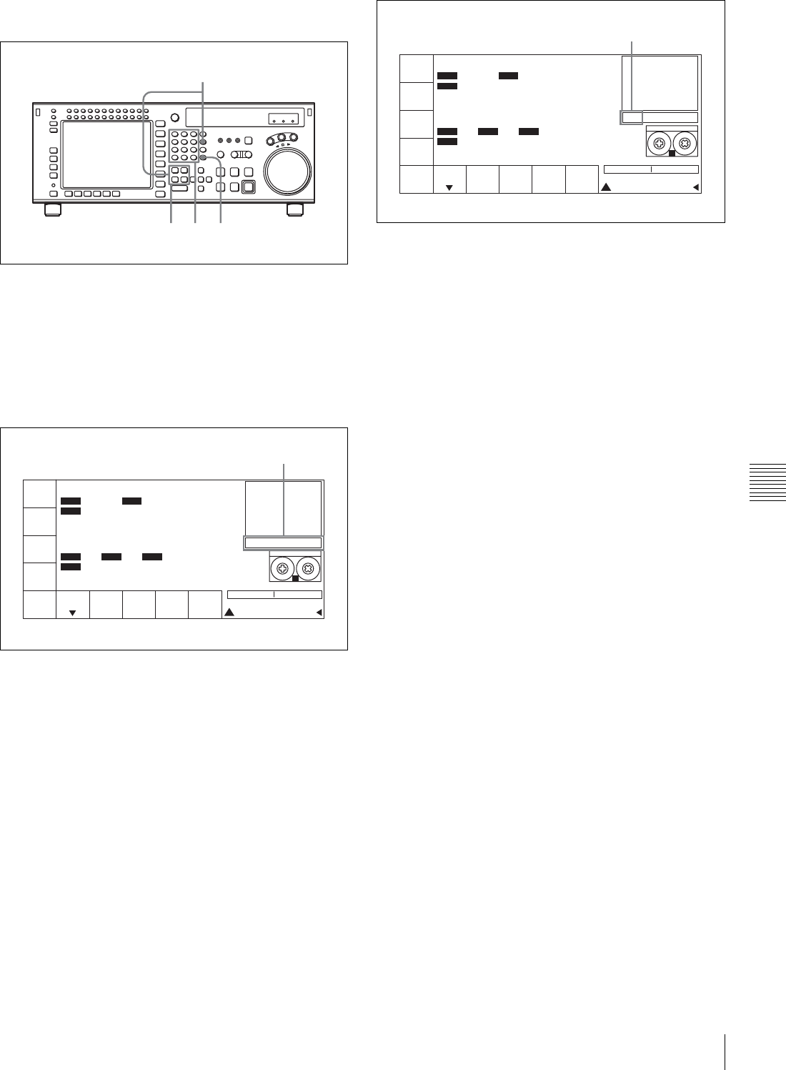
123
6-1 Basic Automatic Editing
Chapter 6 Editing
Moving an edit point position with the numeric
buttons
1
Press one of the IN, OUT, AUDIO IN, or AUDIO
OUT button while holding down the RCL button.
Time data for the edit point appears in the data entry
window.
2
Press the + or – button, then use the numeric buttons to
enter the value to be added or subtracted.
To cancel the entered value
Press the CLR button.
3
Press the SET button.
The result of the addition or subtraction is entered.
4
Press one of the IN, OUT, AUDIO IN, or AUDIO
OUT button.
The modified time data for the edit point appears in the
time data display.
423
1
PB/EE
PB
RECINH
off
ASSEM-
BLE
off
INS
TC
off
INS
VIDEO
off
INS
AUDIO
STILL
! ALT+TC
+ 30 00
01H04M58S00F
01H04M58S00F
AIN 00:01:10:00 AOUT 00:02:10:00
IN 00:01:10:00 OUT 00:02:10:00
INTRP DF F2
INTRP DF 2FO F2
LTC
TCR
2FD
LTC
TCR
HDCAM-SR
REMAIN:01H06M
PLAY LOCK
SS
Data entry window
PB/EE
PB
RECINH
off
ASSEM-
BLE
off
INS
TC
off
INS
VIDEO
off
INS
AUDIO
STILL
! ALT+TC
SET 01 00 30 00
01
H
04
M
58
S
00
F
01
H
04
M
58
S
00
F
AIN 00:01:10:00 AOUT 00:02:10:00
IN 00:01:10:00 OUT 00:02:10:00
INTRP DF F2
INTRP DF 2FO F2
LTC
TCR
2FD
LTC
TCR
HDCAM-SR
REMAIN:01H06M
PLAY LOCK
SS
SET is displayed.
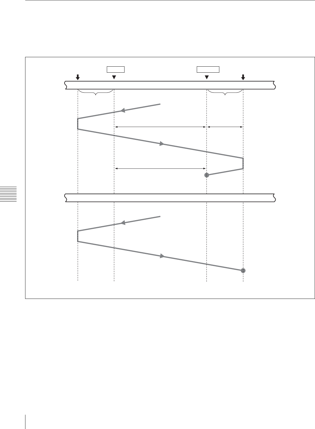
124 6-1 Basic Automatic Editing
Chapter 6 Editing
6-1-10 Performing Automatic Editing
Overview
Once you have set the necessary edit points, the AUTO
button lights up to show that the VTR is ready for
automatic editing.
During automatic editing, the tape in the recorder VTR and
the player VTR move as shown in the diagram below.
a) Preroll time: Factory-set to 5 seconds. Can be set from 0 to 30 seconds, in
units of seconds, through the VTR SETUP menu.
b) The post-roll time can be set between 0 and 30 seconds in units of seconds
using the VTR SETUP menu.
c) Over-recording time: 2 seconds.
Preroll point
Recorder VTR
Player VTR
IN point OUT point Post-roll point
Preroll a)
Playback mode
Playback mode
Insert editing
Assemble editing
Stop
Stop
Post-roll b)
Over-
recording c)
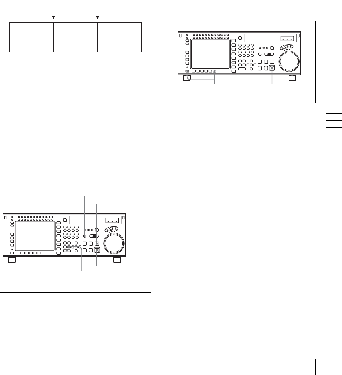
125
6-1 Basic Automatic Editing
Chapter 6 Editing
Monitoring signals during editing
During editing, you can monitor the following video and
audio signals on a monitor connected to the recorder VTR.
• Between preroll and IN points: Playback signal of the
recorder VTR can be monitored.
• Between IN and OUT points: Playback signal of the
player VTR can be monitored in E-E mode.
• Between OUT and post-roll points: Playback signal of
the recorder VTR can be monitored.
The video and audio signals that can be monitored are
shown in the diagram below.
In CONFI mode, you can monitor video and audio signals
that are just being edited.
Through a menu setting, you can also monitor signals
between preroll and postroll points, including portions
between IN and OUT points, through the CONFI
(confidence) heads during editing.
The CONFI setting is made using the VTR SETUP menu
item 017 “PB/EE SELECT MENU”.
To perform automatic editing
To carry out automatic editing, press the AUTO button,
turning it on, then press the REC/EDIT button.
During editing the REC/EDIT button lights up, and goes
off at the end.
To stop automatic editing
Press the OUT button while holding down the ENTRY
button.
The point where the OUT button is pressed is treated as an
OUT point and editing stops.
To confirm the results of the editing
Press the PREVIEW/REVIEW button to confirm the edit
results. When the view ends, the tape rewinds to the OUT
point, then stops.
Modifying edit points for automatic editing
later
After you perform automatic editing, the time data of IN,
OUT, AUDIO IN or AUDIO OUT points remain stored in
memory. The stored data can be used later to modify edit
points or to execute automatic editing again.
Follow the procedure below to modify edit points after
executing automatic editing.
1
In the HOME menu, press the ALT/[F10] (LAST
EDIT) buttons.
The edit points used in the last automatic edit are
restored.
2
Modify the edit points.
For details on modifying edit points, see “6-1-9
Modifying Edit Points” on page 122.
3
Press the REC/EDIT button.
The VTR performs automatic editing.
PB EE PB
IN point
(recorder VTR)
OUT point
(player VTR) (recorder VTR)
AUTO button
PREVIEW/REVIEW button
REC/EDIT button
OUT button
ENTRY button
3
1
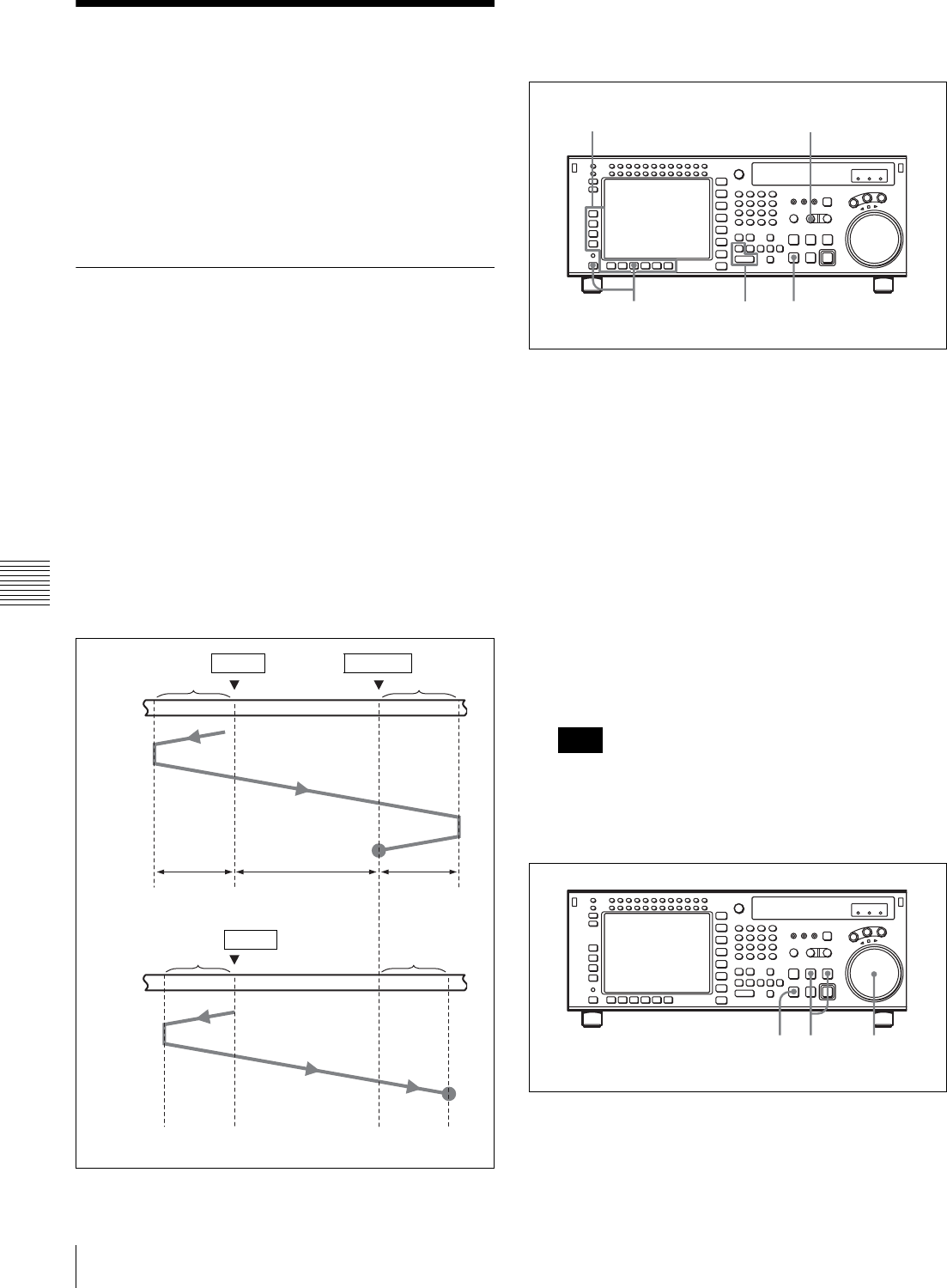
126 6-2 Advanced Automatic Editing
Chapter 6 Editing
6-2 Advanced Automatic
Editing
This section describes the following advanced editing
methods:
• DMC editing
• Animation editing
• Preread editing
6-2-1 DMC Editing
If your player VTR has DT® (Dynamic Tracking)
capability, you can perform variable speed editing by
controlling the playback speed from the lower control
panel. This type of editing is called DMC editing.
Overview of DMC editing
Requirements for DMC editing
• DMC editing may be done during assemble or insert
editing, but not during split editing.
• The player VTR must support DT playback.
Tape movement during DMC editing
During DMC editing, the tape moves as shown in the
diagram below.
Setting edit points and playback speed
Use the procedure below to set edit points and playback
speeds for DMC editing.
1
Press the [F3] (ASSEMBLE) button in the HOME
menu, or press the respective INSERT button ([F4]
(INS TC), [F5] (INS VIDEO), or [F6] (INS AUDIO)
button) to select the edit mode that you want.
2
Press the PLAYER button to set the connected VTR to
act as the player VTR.
The PLAYER button lights up.
3
Press the ALT/[F7] (DMC) buttons in the HOME
menu.
The system enters DMC editing mode.
4
Press the IN button while holding down the ENTRY
button to set an edit point.
You cannot set an OUT point for the player VTR for
DMC editing.
5
Press the STOP button to enter STOP mode.
6
Turn the search dial to set the initial speed.
The selected speed is displayed in the time data
display.
Stop
Recorder
VTR
Player
VTR
IN point OUT point
Preroll Post-roll
Stop
IN point
Playback
mode
DMC editing mode Playback
mode
Preroll time ×
initial speed
Post-roll time ×
final speed
Moves at
the initial
speed. Playback at speeds
stored in memory Moves at
the final
speed.
Note
45
21
3
9 7 6,8
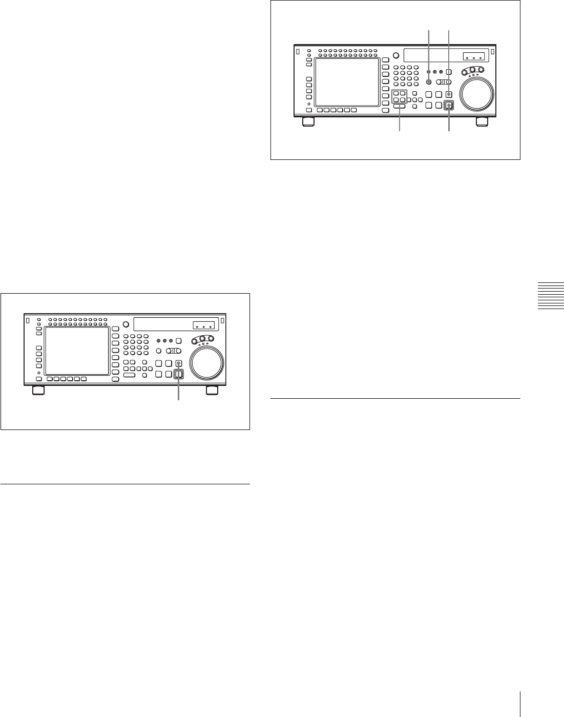
127
6-2 Advanced Automatic Editing
Chapter 6 Editing
7
Press the PREVIEW/REVIEW and PREROLL
buttons at the same time.
The tape prerolls and the player VTR begins playing at
the initial speed.
8
When the x indicator appears with a beep indicating
that the IN point has been passed, rotate the search dial
to the desired playback speed(s).
The varying playback speeds are stored in memory
while the x indicator appears in the display.
9
Press the STOP button.
If the x indicator goes off before you press the
STOP button
The VTR has reached its storage capacity, and cannot store
any more playback speed variations.
To exit DMC editing mode
Press the ALT/[F7] (DMC) buttons in HOME menu.
Performing DMC editing
After setting the playback speeds in preview mode, press
the RECORDER button and REC/EDIT button.
DMC editing is performed at the playback speed(s) stored
in memory.
To confirm the results of DMC editing
Press the PREVIEW/REVIEW button.
6-2-2 Animation Editing
Animation editing is a form of insert editing which makes
it easier to record a succession of still frames in fixed field
or frame units. The procedure for editing after selecting
animation editing is exactly the same as for normal insert
editing.
To select animation editing, use the VTR SETUP menu
item 301 “EDIT OPERATION MODE”.
normal: Selects normal insert editing.
CG: Selects editing in frame units, principally for
recording computer graphics (CG).
When the edit completes, the OUT point
automatically becomes the next IN point, and the next
OUT point is set automatically with 1 frame added.
Follow the procedure below to perform animation editing.
1
Set the IN point.
The OUT point is set automatically.
2
Press the AUTO button.
The button lights up.
3
Press the PREVIEW/REVIEW button to preview.
4
Press the REC/EDIT button.
Automatic editing starts.
When the edit completes, the OUT point automatically
becomes the next IN point, and the next OUT point is
set automatically.
Repeat steps 3 to 4 to perform animation editing.
6-2-3 Preread Editing
Video and digital audio signals already recorded on the
tape can be used as an edit source for insert editing. This
type of editing is called preread editing, as the VTR uses
preread heads to read signals in advance. Signals that are
read in advance can be sent to mixers for mixing, then
recorded to the original channels or other digital audio
channels.
The preread editing settings are performed with the ALT/
[F1] (PRE READ) buttons in the HOME menu.
For details on the settings, see “4-2-4 Preread Settings
(PRE READ)” on page 52.
PREVIEW/REVIEW button
14
23
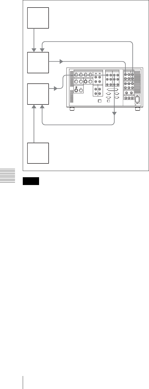
128 6-2 Advanced Automatic Editing
Chapter 6 Editing
• In preread editing, if an input video signal is used as the
reference signal for the output video signal, oscillation
may occur because of loop connections. To avoid this,
select the external reference signal for preread editing by
setting the VTR SETUP menu item 005 “SERVO/AV
REFERENCE select” to “external”.
• When preread mode is selected, no E-E signals are
output in any operation modes to prevent oscillation
caused by loop connections. If preread mode is
deselected while a loop between the input and output of
the same channel exists, E-E signals are output and
oscillation occurs. To prevent oscillation, do the
procedure below to select PB mode for both the video
and digital audio channels before the start of preread
editing.
1
Press the ALT/[F1] (PRE READ) buttons in the
HOME menu and select “on”.
2
Make the required connections for preread editing.
3
Perform preread editing after selecting the insert
editing mode.
4
After preread editing, undo all the connections used
for the preread editing.
5
Press the ALT/[F1] (PRE READ) buttons to select
“off”.
6
Check that no loop connections remain.
Notes
Digital video input
Digital
video
output
Digital
audio
output
Digital
audio
input
Video
switcher
Audio
mixer
Video
source
Audio
source
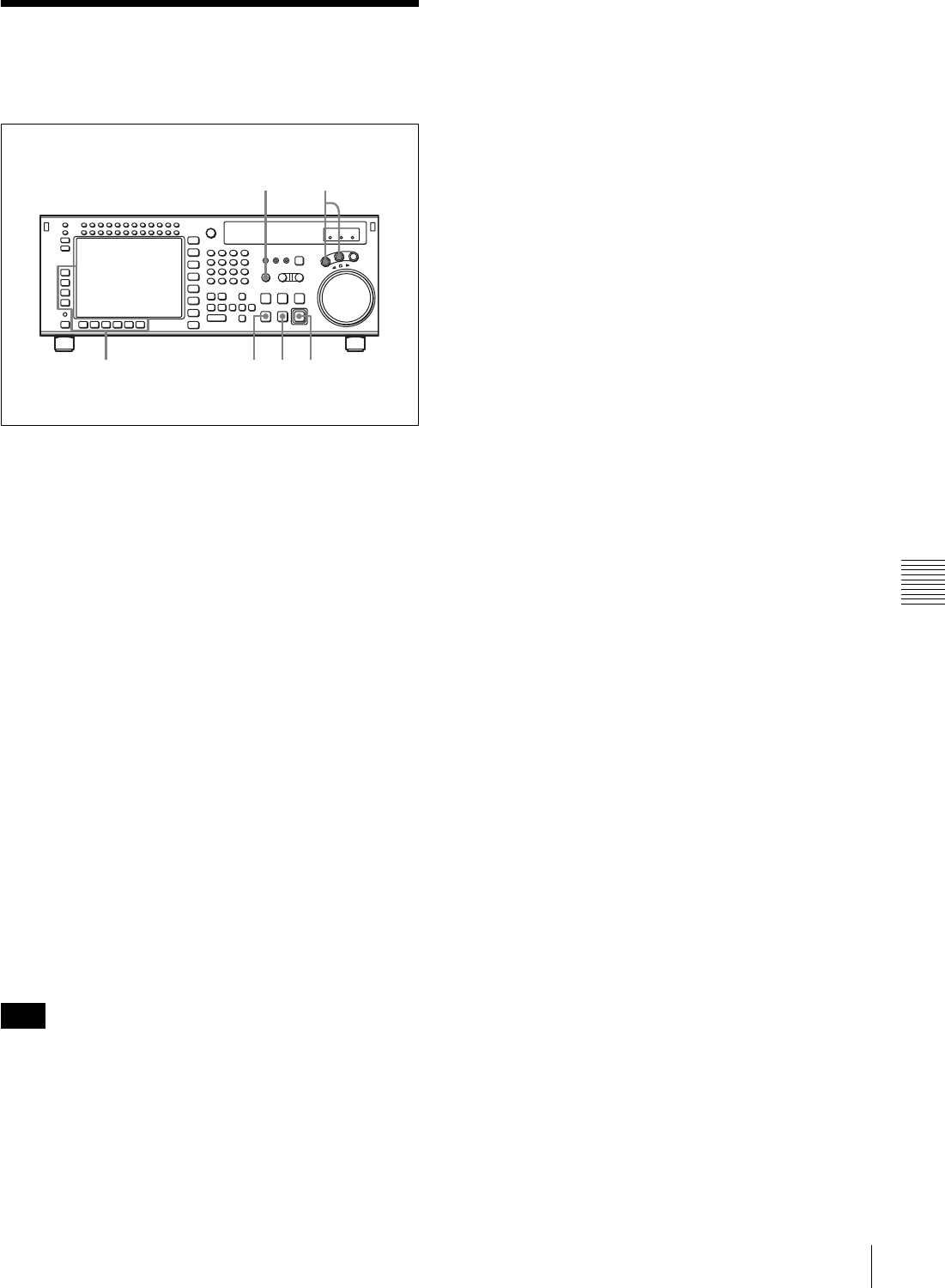
129
6-3 Manual Editing
Chapter 6 Editing
6-3 Manual Editing
Follow the procedure below to perform manual editing.
1
Enter jog or shuttle mode to position the tape at a place
at least three seconds before the position at which you
want to set an edit point.
2
Press the AUTO button to turn it off.
3
Press the [F3] (ASSEMBLE) button in the HOME
menu or press the respective INSERT button ([F4]
(INS TC), [F5] (INS VIDEO) or [F6] (INS AUDIO)
button) to select the edit mode that you want.
4
Press the PLAY button.
Playback starts.
5
Press the REC/EDIT button at the point where you
want to start editing (IN point).
The REC/EDIT button lights, and editing starts.
6
Press the REC/EDIT button at the point where you
want to end editing (OUT point).
Editing ends, but the tape continues to run in playback
mode.
7
Press the STOP button to stop the tape.
To ensure a stable picture, start playback at least three
seconds before the IN point.
Note
4 5,67
21
3
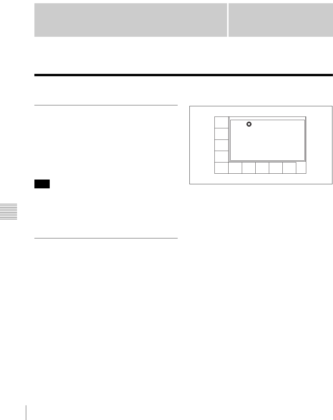
130 Maintenance
Appendix
Appendix
Maintenance
Head Cleaning
Use the BCT-HD12CL Cleaning Cassette to clean the
video and audio heads. Read the instructions included with
the cleaning cassette carefully, as improper usage can
damage the heads.
If you insert the cleaning cassette, it is automatically
ejected after a head cleaning operation which lasts for 10
seconds.
Do not run the cleaning tape more than 6 times in
succession to avoid damaging the heads.
Please refer to the Maintenance Manual Volume 1 on
cleaning the video and audio heads.
Moisture Condensation
If you suddenly move the VTR from a cold location to a
warm one, or use the VTR in a very humid place, moisture
in the air can form on the head-drum or tape guide. This is
called moisture condensation.
If you play a tape under these conditions, the tape may
adhere to the drum where moisture has collected and
become damaged.
If moisture condenses on the head-drum while you are
operating the VTR, the error message “ERROR-10”
appears in the time data display section.
When this error message appears, the VTR enters the
protection mode and certain operations become
inoperable.
Once the moisture has evaporated, the error message
disappears and the VTR becomes normal.
Please refer to the Maintenance Manual Volume 1 on
protection mode.
If “ERROR-10” appears immediately after turning
the VTR on
Leave the VTR turned on and wait until the error message
goes off. Inserting a cassette is not possible while the
message is on.
When the error message disappears, you can use the VTR.
If you move the VTR from a cold to a warm
location
Leave the VTR turned off for about ten minutes since some
time is needed for the condensation-detection mechanism
to work.
Note
00H02M39S18F
PB/EE
LTC
TGA
INTRP DF SFO F2
PLAY LOCK
RECINH
off
ASSEM-
BLE
off
INS
TC
off
INS
VIDEO
off
INS
A-CH2
off
INS
A-CH3
off
INS
A-CH4
off
INS
CUE
off
INS
A-CH1
off
AIN --:--:--:-- AOUT --:--:00:00
IN --:--:--:-- OUT --:--:00:00
ERROR - 10
DEW DETECTED
Total 1 message

131
Specifications
Appendix
Specifications
General
Record format HDCAM-SR (SRW-5000/5500) or
HDCAM (SRW-5500)
Power requirements
100 to 240 V AC, 50/60 Hz
Power consumption
320 W (with all option boards installed)
Peak inrush current
(1) Power ON, current probe method: 54 A (240 V),
17 A (100 V)
(2) Hot switching inrush current, measured in
accordance with European standard EN55103-1:
33 A (230 V)
Operating temperature
+5°C to +40°C (+41°F to + 104°F)
Storage temperature
–20°C to +60°C (–4°F to + 140°F)
Humidity 25% to 80% (relative humidity)
Mass 30 kg (66 lb 26 oz)
Dimensions 427 × 218 × 544 mm (w/h/d)
(16 7/8 × 8 5/8 × 21 1/2 inches)
Tape system
Tape speed HDCAM-SR: 94.1 mm/s (with the frame
frequency of 24 Hz)/98.1 mm/s (with
the frame frequency of 25 Hz)/117.6
mm/s (with the frame frequency of 30
Hz)
HDCAM: 96.7 mm/s (with the frame
frequency of 29.9 Hz)/80.6 mm/s (with
the frame frequency of 25 Hz)/77.4
mm/s (with the frame frequency of 24
Hz)
Digital Betacam: 96.7 mm/s
HDCAM-SR recording and playback time (using BCT-
124SRL)
155 minutes (with the frame frequency
of 24 Hz)/149 minutes (with the frame
frequency of 25 Hz)/124 minutes
(with the frame frequency of 30 Hz)
HDCAM playback time (SRW-5000; using BCT-
124HDL) / HDCAM recording and playback time
(SRW-5500; using BCT-124HDL)
155 minutes (with the frame frequency of
24 Hz)/149 minutes (with the frame
frequency of 25 Hz)/124 minutes (with
the frame frequency of 29.97 Hz)
Digital Betacam playback time (using BCT-D124L)
124 minutes
Fast forward/rewind time
Approx. 4 minutes (using BCT-124SRL)
Search speed
Shuttle mode
HDCAM-SR playback: Still to approx.
±50 times normal playback speed
(with the frame frequency of 24 Hz)
Still to approx. ±48 times normal
playback speed (with the frame
frequency of 25 Hz)
Still to approx. ±40 times normal
playback speed (with the frame
frequency of 30 Hz)
HDCAM playback: Still to approx. ±50
time normal playback speed (with the
frame frequency of 29.97 Hz)/ Still to
approx. ±58 time normal playback
speed (with the frame frequency of 25
Hz)
Digital Betacam playback: Still to
approx. ±50 times normal playback
speed
Variable mode
HDCAM-SR playback: –1 to +2 times
normal playback speed
HDCAM playback: –1 to + 2 time normal
playback speed
Digital Betacam playback: Still to
approx. –1 to +3 time normal playback
speed
Jog mode HDCAM-SR playback: Still to ±2 times
normal playback speed
HDCAM playback: Still to ±3 times
normal playback speed
Digital Betacam playback: Still to ±3
times normal playback speed
Dynamic Tracking range
–1 to +2 times normal playback speed
Load/unload time
7 seconds or less
Recommended tapes
HDCAM-SR cassette (S, L):
BCT-6SR/22SR/40SR
BCT-64SRL/94SRL/124SRL
HDCAM cassette (S, L):
BCT-6HD/12HD/22HD/40HD
BCT-34HDL/64HDL/124HDL
Digital Betacam cassettes (S, L)
(for playback only)
Digital video system
Digital video signal format
Sampling frequency
Y: 74.25 MHz
PB/PR: 37.125 MHz
RGB: 74.25 MHz
Quantization 10 bits/sample
Compression MPEG-4 Studio Profile

132 Specifications
Appendix
Channel coding
S-NRZ
Error correction
Reed-Solomon code
Analog composite output
Bandwidth Y: 0 to 5.75 MHz +0.5 dB/–3.0 dB
S/N ratio 56 dB or more
Y/C delay 15 ns or less
K factor (2T Pulse)
1% or less
Output SCH phase
Conforming to RS-170A/CCIR R.624-3
Digital audio system
Digital audio signal format (HDCAM-SR: CH-1 to
CH-12, HDCAM: CH1 to CH4)
Sampling frequency
48 kHz (synchronized with video)
Quantization 24 bits/sample
Wow and flutter
Below measurable level
Headroom Selectable settings: 20, 18, 16, 15, and 12
dB
De-emphasis T1=50 µs, T2=15 µs (automatically
selected in playback mode)
Analog output
D/A quantization
24 bits/sample
Frequency response
20 Hz to 20 kHz +0.5 dB/–1.0 dB (0 dB
at 1 kHz)
Dynamic range 96 dB or more (at 1 kHz)
Distortion 0.05% or less (at 1 kHz, emphasis on,
reference level)
Crosstalk –80 dB or less (at 1 kHz, between any two
channels)
Input connectors
HD SDI INPUT
A/INPUT MONITOR
BNC (2)
HD SDI (1.485 Gbps) (conforming to
SMPTE 292M/BTA S004B)
B (OPTION)/INPUT MONITOR
BNC (2) (when the optional HKSR-5003
is installed)
REF. INPUT1, REF. INPUT2 (OPTION)
BNC (2 + 2 loop-through)
HD Trilevel SYNC
0.6 Vp-p, 75 Ω, sync negative
SD Black burst
0.286 Vp-p, 75 Ω, sync negative
Selecting HD or SD in a menu
DIGITAL I/O (AES/EBU) INPUT
BNC (6)
CH1/2 to CH11/12
AES/EBU format, unbalanced
AUDIO INPUT CUE (SRW-5500 only)
XLR, 3-pin, female (1)
TIME CODE IN
XLR 3-pin, female (1)
0.5 to 18 Vp-p, 10 kΩ, balanced
Output connectors
HD SDI OUTPUT
A BNC (3, MONITOR with superimposed
text)
SDI (1.485 Gbps) (conforms to SMPTE
292M/BTA S004B)
B (OPTION)
BNC (3) (when the optional HKSR-5003
is installed)
SD SDI OUT BNC (3, MONITOR with superimposed
text)
SD OUT
COMPOSITE (SUPER)
1.0 Vp-p, 75 Ω, sync negative
SYNC Black burst
0.286 Vp-p, 75 Ω, sync negative
FORMAT CONV. OUT (OPTION)
(when the optional HKSR-5001 is
installed)
BNC (2, with superimposed text)
FC OUT B (OPTION)
(when the optional HKSR-5001 is
installed)
BNC (2, with superimposed text)
HD REF. OUT
BNC (2)
1125 SYNC
Tri-level SYNC
0.6 Vp-p, 75 Ω, sync negative
DIGITAL I/O OUTPUT (AES/EBU)
BNC (6)
CH1/2 to CH11/12
AES/EBU format, unbalanced
AUDIO OUTPUT
XLR 3-pin, male (5)
CH1, CH2, CH3, CH4 and CUE (CUE: for HDCAM or
Digital Betacam playback only)
+4 dBm, (with 600 Ω load), low
impedance, balanced
MONITOR OUTPUT L, R
XLR, 3-pin, male (2)
+4 dBm (with a 600 Ω load), low
impedance, balanced
TIME CODE OUT
XLR, 3-pin, male (1)
2.2 Vp-p, low impedance, balanced
PHONES JM-60 stereo phone jack
– ∞ to –12 dBu (with an 8 Ω load),
unbalanced

133
Specifications
Appendix
Remote connectors
ETHERNET RJ-45 modular jack
REMOTE 1-IN(9P)
D-sub 9-pin, female
REMOTE 1-I/O(9P)
D-sub 9-pin, female
VIDEO CONTROL
D-sub 9-pin, female (for optional HKDV-
900)
REMOTE 2 PARALLEL I/O(50P)
D-sub 50-pin, female
Accessories supplied
Operation Manual (English version × 1, Japanese version
× 1)
Installation Manual (English version × 1, Japanese version
× 1)
CD-ROM (1)
Optional accessories
HKSR-5001 Format Converter Board
HKSR-5002 Digital Betacam Playback Board
HKSR-5003 RGB Record Playback Board
RMM-110 Rack Mount Adaptor
BCT-HD12CL Cleaning Cassette
Recommended accessories
For details about recommended accessories, contact your
Sony service representative.
Parallel/serial converters
HD-694 ASTRO DESIGN Corporation or equivalent
XLR/BNC adaptors
BCJ-XP-TRA from CANARE Corporation or equivalent
For optionally available AC power cords, refer to the
supplied Installation Manual.
Design and specifications are subject to change without
notice.
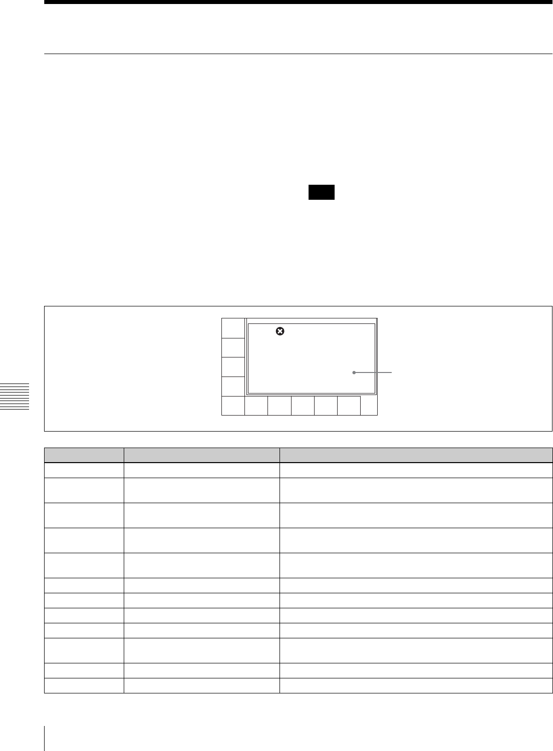
134 Error Messages and Warning Messages
Appendix
Error Messages and Warning Messages
Error Messages
When the unit ceases to operate correctly due to
malfunction or an internal system error, the alarm will
sound and an error message will be displayed on the
display.
Only one message will be displayed even when multiple
errors occur, but the error log menu keeps a history of the
errors.
For more information about error messages, refer to the
Maintenance Manual.
After the error occurs, eliminate the cause of the error and
turn the unit back on. If the error message appears again
when the unit is turned on, contact your Sony
representative.
For more information about eliminating errors, refer to
the Maintenance Manual (Volume 1).
Protection mode
To protect the tape and the mechanical parts of the VTR,
the servo control system automatically stops tape transport
and the drum motor and enters protection mode when an
error occurs.
Cassettes may not be inserted or ejected during protection
mode.
When a cassette is stuck in the unit because of protection
mode, make sure to disconnect the power before removing
the cassette manually.
For information about removing cassettes manually, refer
to the Maintenance Manual (Volume 1).
.
Note
Item number Display Meaning
01 REEL SLACK THREAD ERROR Tape slack was detected during threading or unthreading.
02 REEL SLACK SHTL ERROR Tape slack or a broken tape was detected during search, fast
forward, or rewind.
03 REEL SLACK VAR ERROR Tape slack, a broken tape, or an S-side reel or T-side reel lock was
detected during recording or playback.
04 REEL SPEED ERROR Tape transport speed error was detected during forward winding or
rewinding.
05 REEL FG ERROR When a cassette was inserted, a fault in the S-side reel or T-side
reel operation was detected.
06 OVER TENSION During recording or playback, excess tension was detected.
07 CAPSTAN ERROR A capstan motor operation fault was detected.
08 DRUM ERROR A drum motor operation fault was detected.
09 THREAD TIME OVER A fault was detected in a threading or unthreading operation.
0A FULL TOP ERROR When threading, a failure of the tape beginning processing to
terminate was detected.
10 HUMID DETECT Condensation was detected.
11 TOP END BOTH DETECT The tape beginning and tape end were detected at the same time.
Error message
00H02M39S18F
AIN --:--:--:-- AOUT --:--:00:00
IN --:--:--:-- OUT --:--:00:00
PB/EE
LTC
TCR
INTRP DF 2FO F2
PLAY LOCK
RECINH
off
ASSEM-
BLE
off
INS
TC
off
INS
VIDEO
off
INS
A-CH2
off
INS
A-CH3
off
INS
A-CH4
off
INS
CUE
off
INS
A-CH1
off
AIN --:--:--:-- AOUT --:--:00:00
IN --:--:--:-- OUT --:--:00:00
ERROR - 88
SYS1 - SYS2
INTERFACE ERROR
Total 1 message

135
Error Messages and Warning Messages
Appendix
Warning Messages
When one of the problems described below is detected, a
warning mark is displayed in the upper left corner of the
display. Operation can continue even when the mark is
flashing.
If you press the SFT button (see page 19) and the DIAG
button (see page 18) when the mark is flashing, an
information display appears, showing a warning message.
The warning messages can be viewed in any menu except
the CUE or SET UP menu.
Only one message will be displayed even if there are
multiple messages. The number of errors appears at the
lower right, and you can check the messages using the R
and r buttons.
A history of errors is kept in the error log menu.
For more information about warning messages, refer to
the Maintenance Manual.
Use the displayed warning information to eliminate the
cause of the warning.
For more information about eliminating the cause of
warning, refer to the Maintenance Manual.
To automatically display a warning message
Whenever a warning occurs, change the setting of the VTR
SETUP menu item 120 “WARNING DISPLAY” to “on”.
12 TAPE TOP ERROR A tape beginning sensor fault was detected.
13 TAPE END ERROR A tape end sensor fault was detected.
14 FAN MOTOR ERROR A cooling fan motor operation fault was detected.
20 CC TIME OVER A fault was detected in a cassette compartment raising or lowering
operation.
21 SHIFT TIME OVER A fault was detected movement of the reel table to adjust for
cassette size.
22 POSITION BOTH DETECT The reel table was detected in the L cassette position and S
cassette position at the same time.
23 THREAD BOTH DETECT The threading end and unthreading end were detected at the same
time.
93 DR IF ERROR A communications error between the SV CPU (board SS-95) and
drum CPU (board DR-508) was detected.
97 NVRAM CHECK SUM ERROR An operation fault was detected in the servo system NV-RAM
(board DR-508).
FF SV UNDEFINE ERROR Undefined SV error was detected.
A0 SY UNDEFINE ERROR Undefined SY error was detected.
A2 SY1-SY2 DPRAM ERROR A DPRAM (board SS-95) operation fault between SYS1 and SYS2
was detected.
A5 SY-FC DPRAM ERROR A DPRAM (board FC-91) operation fault between SYS1 and FC
was detected.
A8 SY NVRAM CHECK SUM ERROR A SYS NVRAM (board SS-95) operation fault was detected.
B8 SY1-SY2 INTERFACE ERROR A SYS CPU communications fault was detected.
B9 SY-SV INTERFACE ERROR An SV CPU communications fault was detected.
BA SY-EQ INTERFACE ERROR An EQ CPU communications fault was detected.
BB SY-FC INTERFACE ERROR An FC CPU communications fault was detected.
BC SY-50PIN INTERFACE ERROR A communications fault with the 50-pin CPU was detected.
Item number Display Meaning
Note
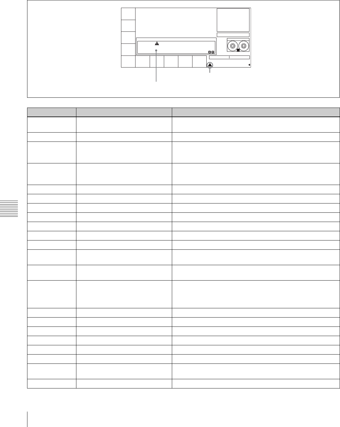
136 Error Messages and Warning Messages
Appendix
To clear a warning message
To cancel the display of a warning message, see “Clearing
warning messages” on page 138.
Item number Display Meaning
01 NO EXTERNAL REFERENCE There is no reference signal on the selected REF. INPUT
connector. The VTR is using an internal reference signal.
02 LOST LOCK Capstan servo lock was lost during playback, recording, or editing.
03 NO EXTERNAL REFERENCE ON
FC
When the VTR SETUP menu item A05 “PD EXT SD REF LOCK
MODE” is set to “lock1” or “lock2”, no external SD reference signal
is input.
04 HD & SD REF ASYNCHRONOUS When the VTR SETUP menu item A05 “PD EXT SD REF LOCK
MODE” in is set to “lock1” or “lock2”, HD reference signal and
external SD reference signal are not synchronized.
05 PLL UNLOCK ON FC The PLL of the HKSR-5001 is not locked on the reference signal.
08 NO SDI INPUT An SDI input signal cannot be detected.
0B VIDEO DATA ERROR The video data channel condition indicator is lit red.
0F AUDIO DATA ERROR The audio data channel condition indicator is lit red.
10 VITC NOT READ VITC cannot be correctly read from the tape.
11 AUDIO PLL UNLOCKED Audio lock generator PLL not locked to the video reference signal.
14 NO PB RF SIGNAL Playback heads cannot correctly read digital data from the tape.
15 INCONSISTENT EMPHASIS Emphasis information on the tape is inconsistent with the system
emphasis status.
16 INCONSISTENT FORMAT OF META
DATA
The meta data being input and the meta data recorded on the tape
have different formats.
17 PB FREQUENCY IS UNSUITABLE The cassette is ejected automatically in line with the setting of the
VTR SETUP menu item 018 “AUTO EJECT LEVEL” because the
system frequency of the VTR and the frequency of the signal
recorded on the tape do not match.
19 NO A1/A2 INPUT No carrier detected on digital audio input on channels 1 and 2
1A NO A3/A4 INPUT No carrier detected on digital audio input on channels 3 and 4
1B NO A5/A6 INPUT No carrier detected on digital audio input on channels 5 and 6.
1C NO A7/A8 INPUT No carrier detected on digital audio input on channels 7 and 8.
1D NO A9/A10 INPUT No carrier detected on digital audio input on channels 9 and 10.
1E NO A11/A12 INPUT No carrier detected on digital audio input on channels 11 and 12.
21 REC INHIBIT MODE The menu settings are to a mode inhibiting recording, or the tape
format does not allow recording.
22 CASSETTE REC INHIBIT The cassette is set to inhibit recording.
Warning message
PRESET
MODE
24F DF
RDTIME
SET
EXITPDTC
DF/NDF
DF
MAINTENANCE INFOMATION DISPLAY
SS
OPERATION
DRUM RUNNING
THREADING
TAPE TRAVEL
529HOURS
34HOURS
20HOURS
780TIMES
[ 26H]
[ 16H]
[ 449H]
STILL
! CUE
WARNING - 08
NO SDI INPUT
Total 8 message
Warning mark
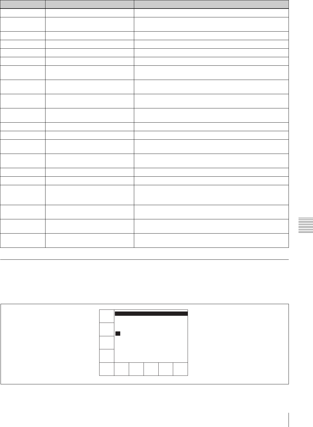
137
Error Messages and Warning Messages
Appendix
Error Log Menu
The time and time codes of errors and warnings occurring
during operation can be displayed in a list form in the
display. (Maximum listing is 99 items.)
To open the error log menu
Press the SFT button (see page 19) and the DIAG button
(see page 18), then press the [F2] (ERR LOG) button.
2D INVALID SDI DATA SDI input signal data is invalid.
34 NO CASSETTE COMPARTMENT
MODE
The cassette compartment does not operate because the VTR is in
“no cassette compartment” mode.
3B NO LTC REPRODUCED LTC signal not detected on the tape.
52 NO SUPPORTED PB FORMAT The recording format cannot be played back by this unit.
53 SYSTEM MISMATCH The tape cannot be played with the current system settings.
55 VIDEO PLL UNLOCKED Video lock generator PLL not locked to the video reference signal.
59 INPUT AUDIO DATA MISMATCH
32.000K
The input audio frequency is wrong.
5A INPUT AUDIO DATA MISMATCH
47.056K
The input audio frequency is wrong.
61 TELEFILE MEMORY IS FULL The remaining capacity of the Tele-File is low, and therefore the
next recording will overwrite old data.
62 NO AREA FOR TELEFILE DATA
ADDITION
There is no space at all in the Tele-File.
63 INVALID FORMAT TELEFILE Parts of the Tele-File format are wrong.
64 TELEFILE DATA WRITE FAIL A write to Tele-File error occurred.
65 NO TELEFILE LABEL The Tele-File could not be recognized, and therefore the cassette is
ejected (HDCAM-SR only).
66 TELEFILE DATA WRITE IS
INHIBITED
Recording or editing was started with the Tele-File in overall write
inhibit mode.
67 TELEFILE DATA READ FAIL A Tele-File read error occurred.
71 INVALID FORMAT CONVERSION The settings do not allow format conversion.
72 REC/EDIT DISABLE CASSETTE
FORMAT
The inserted cassette cannot be recorded or edited because of
system settings (recording format, system line, etc). This display
applies only to HDCAM/HDCAM-SR cassettes (SRW-5500 only).
73 NO REFERENCE INFORMATION Cannot lock because there is no 30 frames/second reference
information in 720/59.94p HD SDI input signals.
74 ASYNCHRONOUS VIDEO INPUT When external sync is selected, the external sync signal and the
HD SDI INPUT signal are more than ±5H out of phase.
77 AUTO CUEUP ABORT Auto cue-up was aborted because the target cue-up time code is 1
second or more away from the current time code.
Item number Display Meaning
95.00:00:00:00 (W) 1B
NO A5/A6 INPUT
96.00:00:00:00 (W) 1C
NO A7/A8 INPUT
97.00:00:00:00 (W) 1D
NO A9/A10 INPUT
95.00:00:00:00 (W) 1E
NO A11/A12 INPUT
TOTAL 99
PAGE
END
PAGE
TOP
ALL
CLEAR
TC
WARNI-
NG
on
ERROR
on
TIME
FULL
MSG
CONDI-
TION
on
EXIT
ERROR LOG '03/06/02 10:27:28

138 Error Messages and Warning Messages
Appendix
For more information about error log menu settings, refer
to the Maintenance Manual.
Clearing warning messages
1
Press the ALT/[F8] (CANCEL EDIT) buttons.
2
Select the message to be cleared using the R and r
buttons.
3
Press the [F2] (MARK) button.
An asterisk “*” will appear in front of the message.
The message will not be displayed or saved.
To cancel clearing
Select the warning message you want to cancel clearing,
and press the [F2] (MARK) button.
Adjusting the clock
Press the ALT/[F9] (REAL TIME) buttons in the error log
menu and use the setting below.
To get current time codes
Hold down the SFT button and press the [F5] (GET TC)
button.
To set the data and time
Hold down the SFT button and press the [F6] (SET) button.
Use the T and t buttons to move the bar to the location
to be adjusted.
Use the numeric buttons to change the value.
To adjust minutes and second to zero
Hold down the SFT button and press [F8] (ZERO) button.
To select daylight saving time and normal time
Hold down the SFT button and press [F9] (SEASON)
button.
STANDARD: normal time
SUMMER: daylight saving time (one hour ahead of
normal time)
Changing between normal and daylight saving times
changes the current time by one hour.
Even if the change crosses midnight, the current date is not
changed.
Button Display Function Setting
[F1] PAGE TOP Move to the top page
[F2] PAGE END Move to the page containing the last message
[F3] FULL MSG Display in full the message selected with the cursor
[F4] ALL CLEAR Clear messages (LOG DATA)
[F5] WARNING Display warning messages on, off
[F6] ERROR Display error messages on, off
[F7] CONDITION Display condition messages on, off
[F9] TIME Toggle between time code and real time display TC, REAL
[F10] EXIT Return to display of maintenance information
ALT/[F8] CANCEL EDIT Display the CANCEL EDIT screen
ALT/[F9] REAL TIME Display the REAL TIME screen
Note

139
Glossary
Appendix
Glossary
AES/EBU format
A standard format for the transfer of
digital audio signals. In this format,
two audio signals can be input/output
through one XLR-type connector.
Assemble editing
An edit mode for adding new scenes
to the end of previously recorded
scenes. New video signals are
recorded for each control signal, but
continuity with the control signal
preceding the edit point is maintained
electrically. Because assemble
editing in the middle of a scene will
cause a break in the video image at
the end of the insertion, this is not a
practical method for inserting new
video data. This should be done with
insert editing.
See also Insert editing.
Backspace editing
Also called phase matching. During
backspace editing, the VTR
automatically rewinds the tape a few
seconds after recording of a scene has
been completed. This allows the tape
to attain a stable speed before the
start of recording of the next scene,
thus maintaining signal continuity
during editing.
Bridging connection
A connection that allows a signal
input to an input terminal to pass
through the unit and exit from an
output terminal for input to a third
piece of equipment.
Capstan
A drive mechanism that moves the
tape at a specified speed. Its rotation
is normally synchronized with a
reference sync signal.
Color frame
A color subcarrier phase having one
cycle that consists of two frames
(four fields) in the NTSC format.
Color frame locking
A procedure in which the time code
frame value is set to an odd number
for the first and second color fields,
and to an even number for the third
and fourth color fields.
Color framing
A method to maintain color
subcarrier phase continuity by
performing editing in two-frame
units in order to achieve stable video
without horizontal fluctuation at the
edit points when editing
downconverted composite video
signal.
Component video signal
A video signal that consists of a
luminance signal (Y) and two
chrominance (color-difference)
signals (R-Y, B-Y).
Composite video signal
A signal that consists of video
(luminance and color sub carrier),
sync (horizontal and vertical), and
color burst signals.
Condensation
Moisture that collects on the head
drum of the tape transport
mechanism, causing damage to the
tape and malfunction of the VTR.
CTL
Abbreviation for control signal. A
pulse signal that can be counted, to
determine the number of frames, and
therefore the tape’s running time.
Used mainly for adjusting the
tracking position of video heads, and
to achieve time code continuity
during continuous recording. This
signal is recorded on a longitudinal
tape track.
Cue point
A point used to mark the beginning of
a section of tape so that it can be
located for later playback or editing.
Drop frame mode
When the field frequency of this unit
is 59.94 Hz, the actual number of
frames per second is approximately
29.97, while the time code value
advances one second every 30
frames. In drop frame mode, the time
code is advanced such a way that this
difference in the value between real
time and the time codes is corrected.
Specifically, two frames are skipped
at the beginning of each minute,
except for every tenth minute, so that
the frame value for time codes
matches that for real time.
See also Non-drop frame mode.
E-E mode
Abbreviation for Electric-to-Electric
mode. In this mode, the signals are
passed through the VTR’s electronics
before output but do not pass through
the magnetic converter circuits such
as the tape and head circuits. This
mode is used for confirming input
signals or adjusting the input level.
Effect edit mode
When editing a tape using a switcher
or when editing special effects, the
pixels comprising the picture are
often not dubbed to the same
positions as those of the original. In
the case of repeated dubbings, this
shifting of pixels produces an
accumulation of calculation errors
during the compression/expansion
process; this may result in an increase
in low-level noise within the signal.
The effect edit mode minimizes the
production of this noise. Note,
however, that a slight loss in picture
resolution may be observed in this
mode.
Emphasis
Emphasizing the high frequencies of
a signal before processing (pre-
emphasis) and de-emphasizing those
high frequencies before output (de-
emphasis). This reduces deterioration
of the signal-to-noise ratio in the high
frequency range.

140 Glossary
Appendix
External synchronization
A method to maintain color
subcarrier phase continuity by
performing editing in two-frame
units in order to achieve stable video
without horizontal fluctuation at the
edit points. For editing, a recorder
VTR (or master VTR) and a player
VTR (or source VTR or slave VTR)
are used, and external
synchronization is commonly used to
ensure that the operation timing
control signals and time reference
signals are synchronized.
Insert editing
An edit mode for inserting new
scenes into the middle of previously
recorded scenes. CTL signals
previously recorded on the tape are
used. Consequently, this mode
cannot be used for blank tapes. This
mode assumes that CTL signals have
somehow be recorded to the tape
already.
See also Assemble editing.
Longitudinal time code
See LTC.
LTC
Abbreviation for Longitudinal Time
Code. This is the time code recorded
onto a longitudinal track of the tape.
During the playback of still pictures,
LTC cannnot be read since the tape is
not moving. During slow playback,
the LTC output is so small that it may
not be read correctly, depending on
the playback speed.
See also VITC.
Non-drop frame mode
In this mode, drop frame mode
processing is not performed. Since
there is no frame cutting, a
discrepancy of about 86 seconds
occurs each day (in the case of a field
frequency of 59.94 Hz) which causes
problems when editing programs in
units of seconds using the number of
frames as a refernce.
See also Drop frame mode.
Preroll
The rewinding of a video tape in the
player or recorder VTR by a certain
length before an edit point, allowing
the tape to attain a stable speed at the
edit point and synchronization with
the other video tape during editing.
Reference video signal
A video signal containing a sync
signal or sync and burst signal, used
as a reference for synchronizing
video equipment.
Servolocking
The locking of the phase and speed of
a VTR’s head drum rotation and tape
transport to a reference signal during
recording and playback.
Standby-off mode
A mode in which head drum rotation
is stopped and tape tension is
released, and thus the VTR is not
ready for immediate recording and
playback. This mode alleviates the
tape and video heads from wear or
damage.
An Standby-on mode
A mode in which the head drum
rotates with the tape wrapped around
it, and thus the VTR is ready for
immediate recording or playback.
The VTR enters standby-off mode
after remaining in standby-on mode
for a specified length of time to
prevent wear or damage to the tape
and video heads.
Time code
A digital signal recorded on the video
tape that supplies information such as
hour, minute, second and frame
number for each frame to facilitate
the setting of edit points or searching
for specific scenes on the tape.
There are two types of time codes:
SMPTE (for the NTSC color system)
and EBU (for the PAL/SECAM color
system); and two time code recording
formats: LTC (longitudinal time
codes) which are CTL signals and
audio signals simultaneously
recorded longitudinally on the tape
and VITC (vertical interval time
codes) which are recorded on the
video signal track.
Tracking
The synchronizing of the head drum
rotation phase and tape transport
phase during playback and recording.
Tracking is adjusted to eliminate
picture instability when playing back
material recorded on another VTR.
User bits
A recordable 32-bit section in each
time code on a video tape for
recording such information as the
recording year, month, and day, and
the tape or program ID number.
Vertical interval time code
See VITC.
VITC
Abbreviation for Vertical Interval
Time Code. This is a time code
recorded on a video signal track
during the vertical blanking interval.
This VTR writes this time code in the
AUX data area in the video signals. It
can be read correctly even during
slow or still picture playback.
See also LTC.

141
Menu List
Appendix
Menu List
This section describes all of the VTR SETUP menu items.
The VTR SETUP menu items are divided into the
following categories by the function.
• Items relating to VTR operations (Nos. 001 to ...)
• Items relating to operation panels (Nos. 101 to ...)
• Items relating to the remote interface (Nos. 201 to ...)
• Items relating to editing (Nos. 301 to ...)
• Items relating to prerolling (Nos. 401 to ...)
• Items relating to recording protection (Nos. 501 to ...)
• Items relating to the time code (Nos. 601 to ...)
• Items relating to the video control (Nos. 706 to ...)
• Items relating to the audio control (Nos. 807 to ...)
• Items relating to digital process (Nos. 902 to ...)
• Items relating to pulldown control (Nos. A01 to ...)
• Other items (Nos. T01 to ...)
For VTR SETUP menu operations, see “4-7-1 VTR
SETUP Menu” on page 98.
In the “Setting” column of the table, the factory default
settings are indicated by an exclosing box.
Items Relating to VTR Operations (Nos. 001 to ...)
Item number Item Setting Function
001 PRE-READ [off]
on
Selects the pre-read (read-before-write) mode for insert
editing.
off: No pre-read operation
on: Pre-read operation
002 REC INHIBIT select [off]
all/crash REC/video
CTL/audio CTL
casst
Selects the record inhibit mode.
off: Recording is enabled. (The REC INHIBIT indicator
does not light.)
all/crash REC/video CTL/audio CTL: Recording is inhibited
on the set channels.
The scope of inhibiting recording is determined by
menu item 003.
casst: When the recording protection plug on the cassette
is pushed in, this setting is displayed. This setting
cannot be selected.
003 REC INHIBIT
AREA select
[all]
crash REC
video/CTL
audio/CTL
casst
Selects the scope to which inhibiting recording applies.
all: All recording is inhibited. (The REC INHIBIT indicator
lights.)
crash REC: The normal recording mode is inhibited. Use
this setting when you wish to record in assemble
editing or insert editing only.
video/CTL: Recording of video and CTL is inhibited.
audio/CTL: Recording of audio and CTL is inhibited.
casst: When the recording protection plug on the cassette
is pushed in, this setting is displayed. This setting
cannot be selected.
The REC INHIBIT indicator lights or flashes to indicate the
state of the recording inhibit mechanism on the cassette.
For details, see item 104.

142 Menu List
Appendix
005 SERVO/AV
REFERENCE select
[input]
auto
external
The servo reference is determined by the following menu.
input: The reference signal is obtained from the HD SDI
INPUT A/B connectors.
auto: During recording and in the edit preset state, the
reference signal is obtained from the HD SDI INPUT A/
B connectors .
When item 001 is not set to “off”, the reference signal is
always external.
In all other cases, the servo operates using the signal
selected in item 006 as the reference signal. If the
signal selected in item 006 is not present, the servo
operates using an internal reference signal.
external: The servo reference signal is always external.
006 EXTERNAL
REFERENCE select
[extrn HD]
extrn SD
When item 005 is set to “external”, this selects the signal
used as reference by this unit.
extrn HD: The signal input to the REF. INPUT 1 connector
is used as the tri-level HD reference signal for playback
and audio signal recording.
extrn SD: The signal input to the REF. INPUT 1 connector
is used as the SD reference signal for playback and
audio signal recording.
007 SYNC PLAY [off]
on
This is the mode for automatic correction at the start of
playback. In sync play mode, for example when playing
back the VTR from a preroll point, the IN point is reached
after exactly the preroll time has elapsed.
off: Selects normal playback mode.
on: Activates the sync play function for playback.
Note
In sync play mode, the time after the tape transport starts
until the video and sound appear is longer than in the
normal playback mode.
008 LOCAL FUNCTION
ENABLE
all disable
all enable
local key map
When this unit is used in remote control mode, this selects
which buttons on the control panel operate.
all disable: All switches and buttons are disabled.
stop & eject: Only the STOP and EJECT buttons operate.
all enable: All switches and buttons except the RECORDER
and PLAYER buttons are enabled.
local key map: Only the buttons enabled in item 009 are
operational.
Item number Item Setting Function
[stop eject]
&

143
Menu List
Appendix
Item number Item Setting Function
009 LOCAL KEY MAP Sets the LOCAL KEY MAP.
Sub items
STOP [disable]
enable
disable: The STOP button is disabled in remote control
mode.
enable: The STOP button operates in remote control mode.
PLAY [disable]
enable
disable: The PLAY button is disabled in remote control
mode.
enable: The PLAY button operates in remote control mode.
REC/EDIT [disable]
enable
disable: The REC/EDIT button is disabled in remote
control mode.
enable: The REC/EDIT button operates in remote control
mode.
STANDBY [disable]
enable
disable: The STANDBY button is disabled in remote control
mode.
enable: The STANDBY button operates in remote control
mode.
EJECT [disable]
enable
disable: The EJECT button is disabled in remote control
mode.
enable: The EJECT button operates in remote control
mode.
JOG [disable]
enable
disable: The JOG button is disabled in remote control
mode.
enable: The JOG button operates in remote control mode.
SHUTTLE [disable]
enable
disable: The SHUTTLE button is disabled in remote control
mode.
enable: The SHUTTLE button operates in remote control
mode.
VAR [disable]
enable
disable: The VAR button is disabled in remote control
mode.
enable: The VAR button operates in remote control mode.
PREROLL [disable]
enable
disable: The PREROLL button is disabled in remote control
mode.
enable: The PREROLL button operates in remote control
mode.
PREVIEW/
REVIEW
[disable]
enable
disable: The PREVIEW/REVIEW button is disabled in
remote control mode.
enable: The PREVIEW/REVIEW button operates in remote
control mode.
AUTO [disable]
enable
disable: The AUTO button is disabled in remote control
mode.
enable: The AUTO button operates in remote control
mode.
INPUT CHECK [disable]
enable
disable: The INPUT CHECK button is disabled in remote
control mode.
enable: The INPUT CHECK button operates in remote
control mode.
MENU&CURSOR [disable]
enable
disable: The menu buttons and the cursor control buttons
are disabled in remote control mode.
enable: The menu buttons and the cursor control buttons
operate in remote control mode.
MONITOR [disable]
enable
disable: The MONITOR button is disabled in remote
control mode.
enable: The MONITOR button operates in remote control
mode.

144 Menu List
Appendix
017 PB/EE SELECT
MENU
Selects output video and audio signals.
Sub items
STAND BY OFF PB/MU
[EE/EE]
Selects the video and audio output signals in the “standby
off” mode.
PB/MU: The playback video signal is output. The audio
output is muted.
EE/EE: The input video and audio signals are output.
STAND BY ON [PB/MU]
EE/EE
EE/MU
Selects the video and audio output signals in the “standby
on” mode.
PB/MU: The playback video signal is output. The audio
output is muted.
EE/EE: The input video and audio signals are output.
EE/MU: The input video signal is output. The audio output
is muted.
REC [PB/PB]
EE/EE
Selects the video and audio output signals during
recording.
PB/PB: The playback video and audio signals are output.
EE/EE: The input video and audio signals are output.
SHUTTLE [PB/MU]
EE/EE
PB/PB
Selects the video and audio output signals during shuttle
playback.
PB/MU: The playback video signal is output. The audio
output is muted.
EE/EE: The input video and audio signals are output.
PB/PB: The playback video and audio signals are output.
JOG [PB/PB]
PB/MU
Selects the video and audio output signals during jog
playback.
PB/PB: The playback video and audio signals are output.
PB/MU: The playback video signal is output. The audio
output is muted.
VAR [PB/PB]
PB/MU
Selects the video and audio output signals during “variable”
playback.
PB/PB: The playback video and audio signals are output.
PB/MU: The playback video signal is output. The audio
output is muted.
018 AUTO EJECT
LEVEL1
(HDCAM-SR)
[off]
LEVEL1
LEVEL2
Selects the condition under which the cassette is
automatically ejected after being played back for a few
seconds.
When the cassette is ejected in accordance with this
setting, the warning message “17 PB FREQUENCY IS
UNSUITABLE” appears in the display.
off: The cassette is not ejected.
LEVEL1: When a tape without video playback compatibility
is played back, the cassette is automatically ejected.
There is no playback compatibility between 4:2:2
format, 4:4:4 format, and 720P format.
LEVEL2: The cassette is ejected when the field frequency,
PsF mode, or interlace mode of the tape differs from
that of the VTR.
Item number Item Setting Function

145
Menu List
Appendix
Items Relating to Operation Panels (Nos. 101 to ...)
019 AUTO EJECT
LEVEL2
(HDCAM)
[off]
LEVEL1
LEVEL2
LEVEL3
Selects the tape conditions under which a cassette is
automatically ejected in playback (after approx. 3 seconds
playback).
When the cassette is automatically ejected, a warning
message “17 PB FREQUENCY IS UNSUITABLE” appears.
off: The cassette is not ejected.
LEVEL1: When a tape without audio playback compatibility
is played back, the cassette is automatically ejected.
There is no playback compatibility between playback frame
rates of 24, 25 fps and 30 fps. (There is compatibility
for PsF, interlacing, or 0.1% discrepancy.)
LEVEL2: Excluding a tape with compatibility for a
frequency discrepancy of 0.1%, when a tape without
compatibility is played back, the cassette is
automatically ejected.
LEVEL3: When a tape other than in the mode selected as
the system is played back, the cassette is automatically
ejected. (This includes PsF, and interlace mode
differences.)
020 P PLAY [off]
on
Selects the mode for output of program play video and
audio from the FC OUT connectors.
off: Use the normal mode.
on: Program play video and audio is output.
Item number Item Setting Function
Item number Item Setting Function
101 SELECTION FOR
SEARCH DIAL
ENABLE
dial direct
[via search key]
Determines how the unit is set to search mode.
dial direct: The unit enters search mode when you rotate
the search dial in all modes except recording and edit
modes.
via search key: The unit enters search mode when you
press the SHUTTLE, JOG or VAR button.
102 REFERENCE
SYSTEM ALARM
off
[on]
Specifies where or not to display a warning when audio/
video reference signal selected in item 005 is not present or
out of phase with the input video signal.
off: No warning is displayed.
on: Warning is displayed by flashing STOP button.
104 REC INHIBIT
LAMP FLASHING
off
[on]
Specifies whether the REC INHIBIT indicator lights or
flashes, when record-protect plug on the back side of the
inserted cassette tape is pressed down.
off:The REC INHIBIT indicator lights up.
on:The REC INHIBIT indicator flashes.
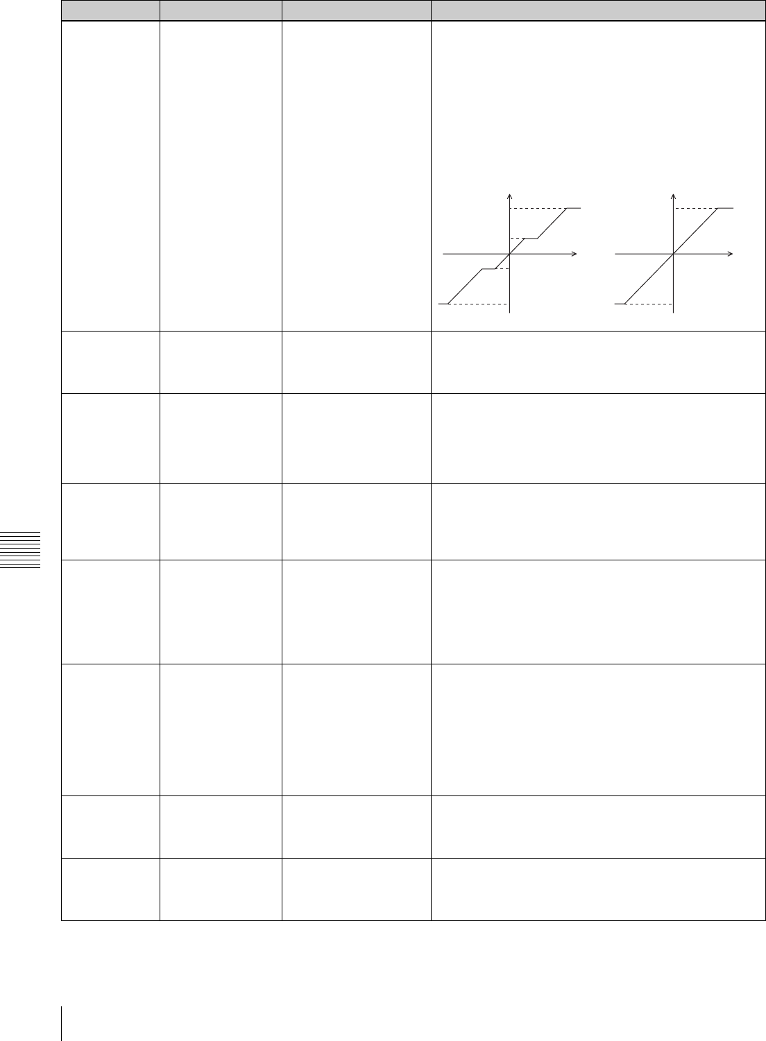
146 Menu List
Appendix
107 JOG DIAL
RESPONSE
[type1: -1 to +1]
type2: –2 to + 2
type3: –2 to + 2
Selects the tape speed (VTR command) characteristics for
search dial rotation.
TYPE1: Tape speed changes linearly in a range of –1 to +1
times normal tape speed.
TYPE2: Tape speed changes in a range of –2 to +2 times
normal tape speed as shown below in TYPE2. (Tape
speed does not change when the search dial is within a
range of ±1 times normal tape speed.)
TYPE3: Tape speed changes linearly in a range of –2 to +2
times normal tape speed as shown below in TYPE3.
109 KEY INHIBIT [off]
on
When this is set to ON, the “KEYINH” indicator in the
information display appears, and the editing control block,
tape transport control block, search control block, and
REMOTE button are disabled.
111 VARIABLE SPEED
LIMIT IN KEY
PANEL CONTROL
[off $-1 to +2%]
on ( 0 to +1)
Sets the the tape speed range during variable-speed (VAR)
playback on the control panel of this unit.
off (–1 to +2): The range of the tape speed is –1 to +2 times
normal speed.
on (0 to +1): The range of the tape speed is 0 to +1 time
normal speed.
112 CTL LOCK IN VAR/
SHTL
[off]
–1/–0.5/0.5/1.0/2.0
CTL locks the tape transport during variable-speed
playback or shuttle playback.
off: CTL does not lock.
–1/–0.5/0.5/1.0/2.0: CTL locks the tape transport at speeds
of –1, –0.5, 0.5, 1.0, and 2.0 times normal speed.
113 DT MODE [field $-1 to +1%]
frame
Sets the DT operation mode.
field (–1 to +1): Enters the field playback mode (Field DT
mode) when the tape speed is –1 to +1 times normal
speed.
Enters the frame playback mode (Frame DT mode)
when the tape speed is +1 to +2 times normal speed.
frame: Enters the frame playback mode (Frame DT mode).
114 POWER-ON MENU
select
[HOME menu]
TC menu
VIDEO menu
AUDIO menu
CUE menu
PF1 menu
PF2 menu
ALT+PF1 menu
ALT+PF2 menu
Selects the menu displayed when the unit is powered on.
115 KEY BEEP high
mid
low
[off]
Selects the volume of the key click sound.
116 ALARM BEEP [high]
mid
low
off
Selects the volume of the alarm sound.
Item number Item Setting Function
FWD
+2
+1
RVS
-1
-2
FWDRVS
TYPE2
FWD
+2
RVS -2
FWDRVS
TYPE3
speed speed
rotation rotation

147
Menu List
Appendix
117 SCREEN SAVER 3 min
10 min
60 min
[off]
Selects the time after which the screen saver function
operates for the color display.
118 SCREEN SAVER S [off]
on
Set the screen-saver for the information display.
off: Do not use screen-saver.
on: Use screen-saver.
The information display reverses at regular intervals.
120 WARNING
DISPLAY
[off]
on
Selects whether warning messages should be displayed in
the lower part of the time code display for the HOME menu,
the TC menu, the PF1 menu, and the PF2 menu.
off: Do not display warning messages.
on: Display warning messages.
Notes
• No warning messages are displayed for the CUE menu,
so check by viewing a menu other than the CUE menu.
• If LOST LOCK occurs during playback or recording, a
LOST LOCK warning message is always displayed.
121 INFO DISPLAY
MODE
rotation
latch
[momentary]
Sets the display mode for the information display.
rotation: The display automatically changes in sequence, at
regular intervals.
latch: Hold down the MULTI CONTROL knob and turn it to
change the display, which remains unchanged when
you release the knob.
momentary: Hold down the MULTI CONTROL knob and
turn it to change the display; after a set time interval,
the display reverts to the first page.
122 MULTI CUE CLEAR
by inject
[on]
off
Selects whether to erase cue point data in multi-cue mode
when a cassette is inserted.
on: Erase cue point data.
off: Do not erase cue point data.
124 Tele-File MENU
auto popup
[off]
on
Specifies whether or not the TELE FILE menu appears
automatically when a cassette with a memory label is
inserted.
off: The TELE FILE menu does not appear.
on: The TELE FILE menu appears.
125 Tele-File THREAD
COUNTER clear
mode
[not clear]
when format
Specifies whether or not the thread counter is reset when a
memory label is formatted.
not clear: The thread counter is not reset.
when format: The thread counter is reset.
126 Tele-File ENTRY
POINT
IN/OUT Point
[CUE Point]
Specifies whether or not to display the log data (IN and
OUT points) in the TELE FILE menu.
IN/OUT Point: The log data (IN and OUT points) is
displayed.
CUE Point: The log data (IN and OUT points) is not
displayed.
127 Tele-File IN OUT
Input Continue
on
[off]
Specifies whether or not to input the log data (IN and OUT
points) continuously in the TELE FILE menu.
on: The log data (IN and OUT points) can be input
continuously.
off: The log data (IN and OUT points) cannot be input
continuously.
128 Tele-File Real Date/
Real Time Mode
[without]
with
When recording Tele-File data, select whether to record the
real date/time.
without: Do not record real date/time.
with: Record real date/time.
Item number Item Setting Function
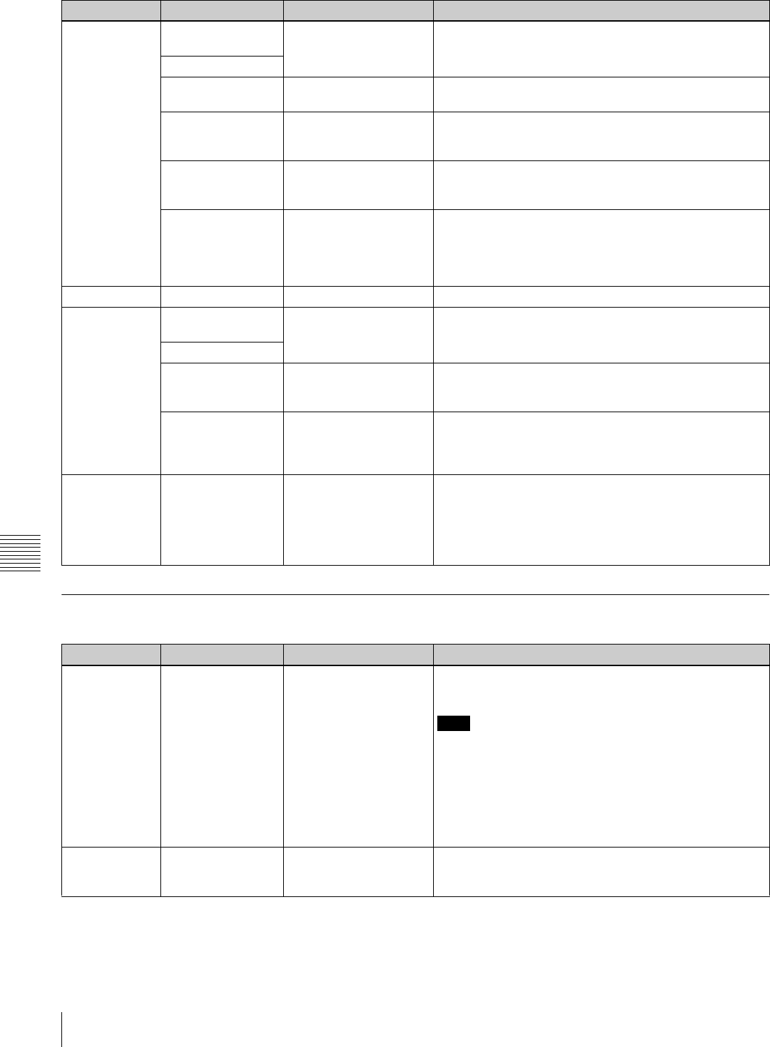
148 Menu List
Appendix
Items Relating to Remote Interface (Nos. 201 to ...)
129 STOP CODE
FUNCTION
Stop code detection mode and adjustment of stop position
when a stop code is detected.
Sub items
DETECT BEEP on
[off]
on: When a stop code is detected, sound a beeper.
off: When a stop code is detected, do not sound a beeper.
DETECT STOP on
[off]
on: When a stop code is detected, stop the tape. (“D-
STOP” appears in the information display.)
off: When a stop code is detected, do not stop the tape.
STOP ADJUST 150 fr
[0 fr]
When a stop code is detected, adjust the tape stop position
from the normal stop position in the direction of the SOM
point (program start point), in the range 0 to 150 frames.
REC ADJUST 5sec
4sec
[3sec]
2sec
1sec
Specifies how many seconds before the SOM point to start
recording a stop code.
130 S-LCD DIMMER 16 to [11] to 0 Adjusts the information display luminance.
131 CHANGED MENU
HIGHLIGHT
Changes the display color of items whose setting has been
changed.
Sub items
ITEM SETTING [off]
on
off: Changed menu setting values do not change display
color.
on: Changed menu setting values are displayed in yellow.
DEFAULT
SETTING
[off]
on
off: Menu numbers with changed DEFAULT values do not
change display color.
on: Menu numbers with changed DEFAULT values are
displayed in yellow.
132 KNOB MODE [set default]
move window
Selects the behavior of the unit when the MULTI CONTROL
knob is pressed during VTR SETUP menu operations.
set default: When a setting value is being selected, selects
the default value.
move window: Move between the item window and the
window for changing values.
Item number Item Setting Function
201 REMOTE 9-PIN [off]
on
When this is set to “on”, this unit is controlled from the
device connected to the REMOTE 1-IN(9P) or REMOTE 1-
I/O(9P) connectors.
Note
When this unit is controlled by a device connected to the
REMOTE 1-IN(9P) or REMOTE 2 PARALLEL I/O(50P)
connector, the editing control buttons and all of the tape
transport buttons except STOP and EJECT are disabled. It
is also possible to make a setting so that all of the buttons
are disabled.
For details, see item 008.
202 REMOTE 50-PIN [off]
on
When this is set to “on”, this unit is controlled from the
device connected to the REMOTE 2 PARALLEL I/O(50P)
connector.
Item number Item Setting Function
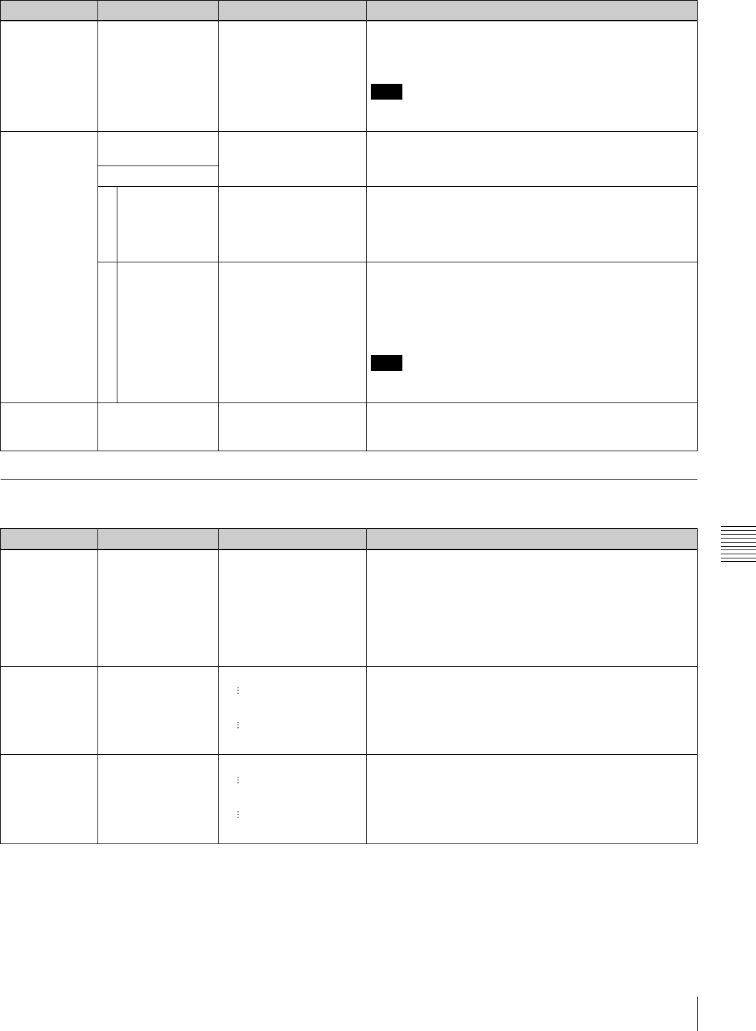
149
Menu List
Appendix
Items Relating to Editing (Nos. 301 to ...)
203 PARALLEL
RUNNING
[disable]
enable
Selects whether two or more VTRs can be operated
synchronized.
disable: Synchronized operation is not carried out.
enable: Synchronized operation is enabled.
Note
For synchronized operation to be possible, this item must
be set to “enable” on all of the connected VTRs.
204 VIDEO REMOTE
CONTROL SELECT
Make settings for control from HKDV-900/503 via the
VIDEO CONTROL (15P) connector.
Sub item
1IMAGE
ENHANCER
U&D
UP
[DOWN]
Select whether to control the up-converter or down-
converter whether controlling the image enhancer.
U&D: Control both the up-converter and down-converter.
UP: Control the up-converter.
DOWN: Control the down-converter.
2 D2 SETUP BLACK
[SETUP]
Select the menu item to be controlled by the SETUP dial on
the HKDV-900/503 with the D2 button pressed.
BLACK: Control menu item 743.
SETUP: Control menu item 762.
For details, see items 743 and 762.
Note
After changing the setting for this item, power off this unit or
HKDV-900/503 and power it on again.
205 REMOTE
NETWORK
on
[off]
Specifies whether or not control from a network is possible.
on: Allows control from a network.
off: Does not allow remote control from a network.
Item number Item Setting Function
301 EDIT OPERATION
MODE
CG
[normal]
Selects the animation edit mode. For normal editing, use
the “normal” setting.
CG: Primarily for recording computer graphics, this setting
allows editing by individual frames. When the edit is
completed, the OUT point automatically becomes the
next IN point. The next OUT point is automatically set
one frame ahead of the IN point.
normal: Use this setting for normal editing.
302 PREROLL TIME 0 sec
[5 sec]
30 sec
This sets the preroll time. The range is from 0 to 30
seconds, in steps of 1 second. The preroll time should
generally be set to at least 3 seconds, and for phase
adjustment with an editing controller it is recommended to
set the preroll time to at least 5 seconds.
303 POSTROLL TIME 0 sec
[5 sec]
30 sec
This sets the tape running time after passing the OUT point
(postroll time) in automatic editing.
The range is from 0 to 30 seconds, in steps of 1 second.
Item number Item Setting Function

150 Menu List
Appendix
304
VAR SPEED RANGE
FOR
SYNCHRONIZATION
[-1 to +2]
–1.15 to +2.45
Specifies the variable tape speed range when the variable
speed playback is executed by a remote control unit
connected to the REMOTE 1-IN(9P) connector.
–1 to +2: –1 to +2 times normal tape speed
–1.15 to +2.45: –1.15 to +2.45 times normal tape speed
Note
When an editing control unit such as BVE-9100 is
connected for DT editing, select “–1.15 to +2.45”.
305 EDIT FIELD select [1F]
2F
1F/2F
Selects the start timing for editing when performing tape
editing.
1F: Start editing from field 1 and end on field 2.
2F: Start editing from field 2 and end on field 1.
1F/2F: Following received timing commands.
Note
When the system frequency of this unit is PsF mode, the
unit always operates with the 1F setting.
306 SYNCHRONIZE [accurate]
rough
off
When this unit is used as a controller for editing control of
another VTR connected through a 9-pin remote cable, this
selects whether or not to carry out phase synchronization
of the two VTRs, and also the editing accuracy when
carrying out synchronization.
accurate: Editing is carried out with an accuracy of ±0
frames.
rough: Editing is carried out with an accuracy of ±1 frame.
off: Synchronization is not carried out.
311 EDIT PRESET
REPLACE MODE
SELECT
[normal]
parallel
reverse
stereo
normal: Assigns edit preset command channels 1 to 8, to
track channels 1 to 8.
parallel: Assigns edit preset command channels 1 to 4, to
channel pairs 1/5 to 4/8.
reverse: Assigns edit preset command channels 1 to 4 to
channels 5 to 8, and channels 5 to 8 to channels 1 to 4.
stereo: Assigns edit preset command channels 1 to 4 to
track channel pairs 1/2 to 7/8.
312 ANALOG AUDIO
EDIT PRESET
REPLACE
[no def]
ch1
ch2
ch1+2
When the edit presets for VTR channels 9 to 12 are
specified by an editor or remote controller, these are set on
or off according to the analog audio edit presets.
no def: Not set.
ch1: Follows analog channel 1 edit preset.
ch2: Follows analog channel 2 edit preset.
ch1+2: Follows the edit preset for analog channel 1 or
analog channel 2.
Sub items
ANALOG AUDIO
EDIT PRESET
REPLACE FOR
CH9
ANALOG AUDIO
EDIT PRESET
REPLACE FOR
CH10
ANALOG AUDIO
EDIT PRESET
REPLACE FOR
CH11
ANALOG AUDIO
EDIT PRESET
REPLACE FOR
CH12
Item number Item Setting Function
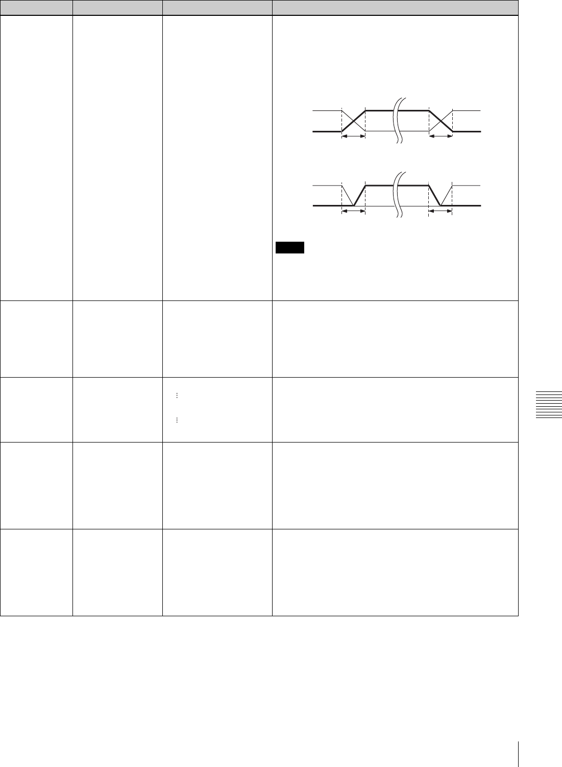
151
Menu List
Appendix
317 AUDIO EDIT MODE cut edit
[cross fade]
fade in/out
Specifies the type of editing for digital audio signals.
cut edit: Cut editing (discontinuity in audio signal may result
at the join, causing noise.)
cross fade: Cross-fade (see figure below.)
fade in/out: Fade-out and fade-in (see figure below.)
Notes
• The “t” in the figures above is the time set by item 811.
• When editing non-audio data, be sure to select “cut edit”.
• Noise may be produced during the editing of certain non-
audio data.
318 EDIT RETRY off
[on]
Set this item when the VTR is used as a recorder during
VTR-to-VTR editing. Specifies the action taken when the
recorder fails to synchronize with the player VTR.
off: Editing is not executed and the VTR enters STOP
mode.
on: The VTR automatically repeats the editing (not more
than twice).
320 PLAY COMMAND
DELAY START
TIME
–30 frame
[0 frame]
+30 frame
This adjusts the time in frames required between the issue
of a playback command and this unit actually beginning the
execution of the command. This adjustment is useful for
synchronization between VTRs with widely differing start-
up timing.
321 VIDEO PREVIEW
MODE
[VVV]
VBV
During a preview operation, this selects the video signals
that can be monitored on the monitor output and line output
connectors.
VVV(VIDEO-VIDEO-VIDEO): In the editing interval the
monitored signal is the player video signal or video
input (EE) signal.
VBV(VIDEO-BLACK-VIDEO): In the editing interval the
monitored signal is a black signal.
322 AUDIO PREVIEW
MODE
[SSS]
SMS
During a preview operation, this selects the audio signals
that can be monitored on the monitor output and line output
connectors.
SSS: SOUND-SOUND-SOUND: In the editing interval the
monitored signal is the player audio signal or audio
input (EE) signal.
SMS: SOUND-MUTE-SOUND: In the editing interval the
audio signal is muted.
Item number Item Setting Function
CROSS FADE
PB
INPUT
FADE IN/OUT
PB
INPUT
IN
IN
OUT
OUT
tt
tt

152 Menu List
Appendix
Items Relating to Prerolling (Nos. 401 to ...)
Item number Item Setting Function
401 FUNCTION MODE
AFTER CUE-UP
[stop]
still
Selects the operation mode that the VTR changes to after
completing a cue up operation.
stop: Enters stop mode.
still: Enters still-picture mode (search mode).
Note
When setting the standard constant on the editor and
control the unit, set to “stop”.
403 CUEUP BY TC capstan only
[reel/capstan]
This setting is only active when item 602 is set to “TC” or
“UBIT”.
capstan only: The tape runs with the pinch ON state during
cue up. (The maximum tape speed is ten times normal
tape speed.)
reel/capstan: The tape runs with the pinch OFF state
during cue up. When the tape nears the cue up point
and tape speed drops to slow, the pinch turns ON.
404 CUEUP BY CTL [capstan only]
reel/capstan
This setting is only active when item 602 is set to “CTL”.
capstan only: The tape runs with the pinch ON state during
cue up. (The maximum tape speed is ten times normal
tape speed.)
reel/capstan: The tape runs with the pinch OFF state during
cue up. When the tape nears the cue up point and tape
speed drops to slow, the pinch turns ON.
When this unit is controlled by an editor (BVE-2000/BVE-
9100, etc), and the setting is “reel/capstan”, cue up
operations are done at high speed.
Select “capstan only” when editing precision has priority.
405 CUE MENU
DEFAULT MODE
select
[page mode]
extend mode
Selects the default mode when the CUE menu is opened.
page mode: PAGE mode
extend mode: EXTEND mode
406 CUE MENU
PREROLL OFFSET
[0 sec]
30 sec
Sets the preroll time for a cueing up operation from the
CUE menu.

153
Menu List
Appendix
Items Relating to Recording Protection (Nos. 501 to ...)
407 AUTO REWIND [off]
on
Selects the rewind mode for the end of the tape.
off: The tape transport stops at the end of the tape.
on: The tape is automatically rewound from the end of the
tape.
408 AUTO CUE UP [off]
on
Selects whether or not to cue up when switching from
standby-off to standby-on.
off: No cue-up.
on: Cue up to the time code immediately before switching
to standby-off.
Item number Item Setting Function
501 STILL TIMER 0.5 sec
5 sec
10 sec
20 sec
30 sec
40 sec
50 sec
1 min
2 min
3 min
4 min
5 min
6 min
7 min
[8 min]
30 min
Select the amount of time after which the VTR to
automatically enters tape-protect mode, for the purpose of
protecting the video head and tape.
This is the time between stopping of the tape (stop mode or
still-picture mode in search mode) and the change to tape-
protection mode.
The selectable range of time is from 0.5 second to 30
minutes.
502 TAPE
PROTECTION
MODE FROM
SEARCH
[step fwd]
standby off
tension release
Specifies the tape-protect mode to which the VTR changes
from still-picture mode while searching (JOG/SHUTTLE/
VAR).
The unit enters automatically the specified tape-protect
mode after the time specified in item 501 has elapsed.
step fwd: A two-second step advance is repeated in
forward direction at 1/30 times normal tape speed.
standby off: The VTR enters standby off mode (standby is
canceled).
tension release: The VTR enters tension release mode
(tape tension is released).
503 TAPE
PROTECTION
MODE FROM STOP
[standby off]
tension release
Specifies the tape-protect mode to which the VTR changes
to from the stop mode.
The unit automatically enters the specified tape-protect
mode after the elapse of time specified by item 501.
standby off: The VTR enters standby off mode (standby is
canceled).
tension release: The VTR enters tension release mode
(tape tension is released).
504 DRUM ROTATION
IN STANDBY OFF
[off]
on
Sets the drum rotation to “on” or “off” during standby-off
mode.
off: Drum rotation is stopped.
on: Drum rotation continues.
505 STILL TENSION [normal]
loose
Sets the tape tension control in still-picture mode.
normal: Maintains the tape tension that ensures uneffected
playback even in still-picture mode.
(This is the normal setting for VTR operations.)
loose: Sets the tape tension lower than that of the “normal”
setting after the VTR enters still-picture mode. In this
case, picture playback is not ensured. (For long
standbys (e.g., LMS) in still-picture mode, this setting is
recommended.)
Item number Item Setting Function

154 Menu List
Appendix
Items Relating to the Time Code (Nos. 601 to ...)
Item number Item Setting Function
601 DF/NDF MODE
select
[drop frame]
non-drop frame
auto
Selects the timing mode for the time code generator and
the CTL counter.
drop frame: drop frame mode (“DF” indication)
non-drop frame: non-drop frame mode (“NDF” indication)
auto: Drop frame / non-drop frame mode is selected
automatically on the basis of the frame frequency of
the unit. For 29.97 Hz drop frame mode is selected,
and for 30 Hz non-drop frame mode is selected. The
setting of the frame frequency mode is carried out with
the [F9](OTHERS CHECK)/ [F9] (SYSTEM) button in
MAINTENANCE menu.
Notes
• This setting is only active when the frame frequency of
the unit is 29.97 Hz or 30 Hz.
• When the [F7](TCG MODE) key is set to “regene” in TC
menu, the time code generator is synchronized to the
playback time code, and therefore this setting is disabled.
602 TIMER MODE
select
CTL
[TC]
UBIT
Selects the mode for displaying time data.
CTL: During playback the CTL signal recorded on the tape,
or during recording the CTL signal being recorded on
the tape, is counted, and the tape running time is
displayed in hours, minutes, seconds, and frames.
TC: The time code value read by the time code reader, or
the time code value generated by the time code
generator is displayed. Use item 603 to toggle between
VITC and LTC.
UBIT: The user bits inserted in the playback time code, or
the user bits inserted in the time code being recorded
are displayed. Use item 603 to toggle between VITC
and LTC.
603 TCR MODE select [LTC]
auto
VITC
Selects the time code read by the time code reader during
playback.
LTC: LTC i s r e a d.
auto: If the playback speed is in the range ±1/2 normal
speed, VITC is read, and if outside this range LTC is
read.
VITC: VITC is read.
604 TC2 MODE SEL UBG
TCG
UBV
UBR
CTL
VITC
auto
LTC
[off]
Selects the time data appearing in the second line.
UBG: Displays UBG.
TCG: Displays TCG.
UBV: Displays UBV.
UBR: Displays UBR.
CTL: Displays CTL.
VITC: Displays VITC.
auto: Displays VITC when the playback speed is in the
range ±1/2 normal speed, and LTC if outside this
range.
LTC: Displays LTC.
off: Does not display time data in the second line.

155
Menu List
Appendix
605 TAPE TIMER
DISPLAY
+/– 12H
[24H]
Selects whether the CTL counter operates in 12-hour
display mode or 24-hour display mode.
+/–12H: 12-hour display mode
24H: 24-hour display mode
Note
In the ±12-hour display, the tens digit of the hours value is
dropped.
606 TCG MODE select [preset]
regene
auto
Selects the time code to which the internal time code
generator synchronizes.
preset: By an operation on the front panel or by remote
control from a device connected to the REMOTE 1-
IN(9P) connector, the initial value of the time code
generated by the internal time code generator can be
preset.
regene: The internal time code generator is synchronized
(“regene”) to the time code values read by the internal
time code generator.
auto: Operates in regene mode when either assemble or
insert mode is selected and operates in preset mode
when any other mode is selected.
607 TCG REGENE
SOURCE select
SDI-LTC
SDI-VITC
ext-LTC
int-VITC
[int-LTC]
If item 606 is set to “regene”, this selects the source of the
synchronization of the time code generated internally.
int-LTC: When the time code played back from the time
code track on the tape is used.
int-VITC: When the time code played back from the “AUX
data” in the video signal on the tape is used.
ext-LTC: When the external time code input to the TIME
CODE IN connector is used.
SDI-VITC: When the VITC input to the HD SDI INPUT
connector is used.
SDI-LTC: When the LTC input to the HD SDI INPUT
connector is used.
608 TCG/UBG REGENE
MODE TC
UB
Selects the regenerate signal when the time code
generator is in regenerate mode (when item 606 is set to
“regene”) or during auto edit mode.
TC & UB: The time code signal and user bits signal are
both regenerated.
TC: The time code signal is regenerated.
UB: The user bits signal is regenerated.
609 REC RUN/FREE
RUN select
[free run]
rec run
This selects the way in which the time code advances.
free run: Regardless of the operation mode of this unit, the
time code advances all the time that the power is on.
rec run: The time code advances only during recording.
Note
When using this setting, set item 606 to “preset”.
610
DOWNCONVERTER
VICT output
[on]
off
Selects whether or not to insert VITC data in the HD-SD
converter output.
on: VITC data is inserted.
off: VITC data is not inserted.
611 VITC POSITION-1
select (NTSC)
12,281 line
[16,279 line]
20,283 line
When 29.97PsF/59.94i mode is selected on the VTR, this
setting specifies the lines in which the VITC signal is
inserted.
It can be inserted in any lines from 12,281 to 20,283.
Note
Items 611 and 612 allow VITC to be inserted in two lines.
Item number Item Setting Function
[TC UB]
&

156 Menu List
Appendix
612 VITC POSITION-2
select (NTSC)
12,281 line
[16,279 line]
20,283 line
When 29.97PsF/59.94i mode is selected on the VTR, this
setting specifies the lines in which the VITC signal is
inserted.
It can be inserted in any lines from 12,281 to 20,283.
Note
Items 611 and 612 allow VITC to be inserted in two lines.
613 TC OUTPUT
SIGNAL IN
REGENE MODE
[off tape]
regene
through
Specifies the signal output to the TIME CODE OUT
connector when the internal time code generator is in a
mode for regenerating the playback time code (i.e. during
auto edit mode or when item 607 is set to “int-LTC” and
item 606 is set to “regene”).
off tape: The playback time code signal is output to the
TIME CODE OUT connector without regeneration.
regene: The playback time code signal is output to the
TIME CODE OUT connector after regeneration only
when the VTR is in playback mode.
through: The time code signal input to the TIME CODE IN
connector is output as it is.
614 PHASE
CORRECTION
[off]
on
Specifies whether the phase correction control of the LTC
signal generated by the time code generator is applied or
not.
off: The phase correction control is not applied.
on: The phase correction control is applied.
616 VITC POSITION-1
select (PAL)
9,322 line
[19,332 line]
22,335 line
When 25PsF/50i mode is selected on the VTR, this setting
specifies the lines in which the VITC signal is inserted.
It can be inserted in any lines from 9,322 to 22,335.
Note
Items 616 and 617 allow VITC to be inserted in two lines.
617 VITC POSITION-2
select (PAL)
9,322 line
[21,334 line]
22,335 line
When 25PsF/50i mode is selected on the VTR, this setting
specifies the lines in which the VITC signal is inserted.
It can be inserted in any lines from 9,322 to 22,335.
Note
Items 616 and 617 allow VITC to be inserted in two lines.
618 LTC OUTPUT
PHASE select
input
auto
[output]
Selects the LTC output phase.
input: Same phase as input video.
auto: When editing, same phase as input video; otherwise
(playback, recording, etc.), same phase as output
video.
output: Same phase as output video.
619 EXT LTC MODE direct
[regene]
Selects the recording mode when the internal time code
generator is set to regenerate the input from the TIME
CODE IN connector (menu item 607 is set to “ext-LTC”, and
menu item 606 is set to “regene”).
direct: Records the time code input from the TIME CODE
IN connector unaltered on the tape.
regene: Regenerates the time code input from the TIME
CODE IN connector with the internal time code
generator.
620 SUPERIMPOSED
CHARACTER
[off]
on
Specifies whether or not to superimpose time data and
operating status information on the signal output from the
MONITOR connector of SD SDI OUT, the SD OUT
COMPOSITE connector and HD SDI OUTPUT connector.
off: No information is superimposed.
on: Information is superimposed.
Item number Item Setting Function

157
Menu List
Appendix
622 CHARACTER H-
POSITION
0
[8]
15
Sets the horizontal position of text information
superimposed on the signal output from the MONITOR
connector of SD SDI OUT, the SD OUT COMPOSITE
connector and HD SDI OUTPUT connector. A setting of 0
displays the information at the left edge of the screen, and
the position moves to the right as the setting is increased.
There are 16 possible settings, from 0 to 15.
623 CHARACTER V-
POSITION
0
[22]
23
Sets the vertical position of text information superimposed
on the signal output from the MONITOR connector of SD
SDI OUT, the SD OUT COMPOSITE connector and HD
SDI OUTPUT connector. A setting of 0 displays the
information at the bottom of the screen, and the position
moves up as the setting is increased. There are 24 possible
settings, from 0 to 23.
Note
If two-line display is selected in item 626, sometimes the
second line will disappear in the middle of the screen.
624 CHARACTER TYPE without BG
outlined
translucent
[with BG]
Sets the style of text information such as time codes output
from the MONITOR connector of SD SDI OUT, the SD OUT
COMPOSITE connector and HD SDI OUTPUT connector.
without BG: White characters, with no background.
outlined: White characters outlined in black.
translucent: White characters on a gray screen
background.
with BG: White characters on a black background.
Note
For the SD SDI OUT connector and SD OUT COMPOSITE
(MONITOR) connector, the “translucent” setting is
automatically changed to “with BG”.
625 CHARACTER SIZE × 1 Sets the size of text information such as time codes output
from the MONITOR of SD SDI OUT, the SD OUT
COMPOSITE connector and HD SDI OUTPUT connectors.
× 1: Normal size.
× 2: Twice normal size.
626 DISPLAY
INFORMATION
select
time data & status
time data & UB
time data & CTL
time data & VITC
[time data only]
When item 620 is set to “on”, this setting specifies the
content of text information output from the MONITOR
connector of SD SDI OUT, the SD OUT COMPOSITE
connector and FORMAT CONV. OUT (OPTION) connector.
time data & status: Timer counter display and status
information.
time data & UB: Timer counter display and user bits.
time data & CTL: Timer counter display and CTL.
time data & VITC: Timer counter display and VITC.
time data only: Timer counter display only.
627 CHAR WARNING
DISPLAY at dual
line mode
[off]
on
When item 626 is set to anything other than “time data
only”, this item specifies whether warning messages flash
on the second line or not.
off: Warning messages do not flash.
on: If a warning message exists, it flashes.
Notes
• Messages that have been cleared are not displayed.
For more information about clearing warning messages,
see “Clearing warning messages” on page 138.
• When there are multiple warning messages, each
message flashes twice before it is replaced by the next
message.
Item number Item Setting Function
[ 2]
×

158 Menu List
Appendix
Items Relating to the Video Control (Nos. 706 to ...)
628 REMAIN TIME
DISPLAY
[off]
10min
on
Sets whether to display remaining time on the tape in
superimposed character position.
off: Do not display remaining time.
10min: Display remaining time when it is 10 minutes or
less.
on: Always display remaining time.
Note
The remaining time on the tape is not displayed when no
cassette is inserted. The remaining time is not also
displayed until the VTR finishes detecting the diameter of
the wound tape and estimating the remaining time
immediately after the cassette is inserted.
630 TC CONVERT [off]
on
Selects whether to convert the playback time code to the
operating frequency time code when tapes recorded with
different frame rates are used for off-speed playback.
off: Does not convert the time code.
on: Converts the time code.
631 ORIGINAL TC
display
[off]
on
When item 630 is set to “on,” this setting specifies whether
the 24-frame time code is displayed or not on the control
panel of the VTR before conversion.
off: The 24-frame time code is not displayed before
conversion.
on: The 24-frame time code is displayed before conversion.
The type of time code displayed is specified by item
603.
632 JUMPING TC
select –2H
–1H
+1H
+2H
+3H
0H
Sets the loopback point (JUMPING TC) for converting time
code with respect to the reference time code (STARTING
TC) for conversion.
–3H: The JUMPING TC is set 3 hours before STARTING
TC.
–2H: The JUMPING TC is set 2 hours before STARTING
TC.
–1H: The JUMPING TC is set 1 hour before STARTING TC.
+1H: The JUMPING TC is set 1 hour after STARTING TC.
+2H: The JUMPING TC is set 2 hours after STARTING TC.
+3H: The JUMPING TC is set 3 hours after STARTING TC.
0H: The JUMPING TC is set 1 frame before STARTING TC.
Item number Item Setting Function
706 FORCED
VERTICAL
INTERPOLATION
OFF
[auto]
forced YADD off
Specifies whether or not Y-add operation mode is
automatically turned on during DT playback.
auto: Y-add operation mode is automatically turned on.
forced YADD off: Y-add operation mode is off all the time.
707 ROUNDING
(SRW-5500 only)
[simple]
adaptive Selects whether to perform A-ROUNDINGTM 1) processing.
simple: Do not perform A-ROUNDINGTM processing. 10-bit
input signals are simply rounded to 8 bits.
adaptive: Perform A-ROUNDINGTM processing. 10-bit
input signals are adaptively rounded to 8 bits.
Item number Item Setting Function
[ 3H]
−
1) A-ROUNDING™
A method for rounding a 10 bit signal to 8 bits. This process suppresses
step noise that occurs when lines which differ slightly from the horizontal
are displayed.
A-ROUNDING is a trademark of Sony Corporation.

159
Menu List
Appendix
708 MASTER LEVEL
(HD)
preset: 100%
(4000H)
0.0% (0H)
141.3% (5A70H)
Adjusts the level of the HD video signal output from the HD
SDI OUTPUT connectors. Simultaneously adjusts the Y,
PB, and PR levels.
709 Y LEVEL (HD)
preset: 100%
(4000H)
0.0% (0H)
141.3% (5A70H)
Adjusts the level of the HD video signal output from the HD
SDI OUTPUT connectors. Adjusts the Y level of the video
signal.
710 PB LEVEL (HD)
preset: 100%
(4000H)
0.0% (0H)
141.3% (5A70H)
Adjusts the level of the HD video signal output from the HD
SDI OUTPUT connectors. Adjusts the PB level of the video
signal.
711 PR LEVEL (HD)
preset: 100%
(4000H)
0.0% (0H)
141.3% (5A70H)
Adjusts the level of the HD video signal output from the HD
SDI OUTPUT connectors. Adjusts the PR level of the video
signal.
712 SETUP LEVEL (HD)
preset: 0
–10.0
[0.0]
10.0
Adjusts the level of the HD video signal output from the HD
SDI OUTPUT connectors. Adjusts the setup level of the
video signal.
713 SYNC PHASE (HD)
preset: 0
–128
[0]
127
Controls the H sync phase of the HD video signal output
from the HD SDI OUTPUT connectors, according to the
menu.
714 FINE (HD)
preset: 0
[0]
1024
Controls the H sync phase of the HD video signal output
from the HD SDI OUTPUT connectors, according to the
menu.
720 HD OUT BLANK [through]
blank
Turns on and off vertical interval blanking processing of the
HD video signals output from the HD SDI OUTPUT
connectors and the FORMAT CONV. OUT (OPTION)
connectors.
through: Do not perform blanking processing.
blank: Perform blanking processing.
740 VIDEO GAIN (ALL)
(HD/UC/SD/DC)
preset: 100%
(4000H)
0.0% (0H)
141.3% (5A70H)
Adjusts the video gain of HD, UC, SD, and DC output. The
video level increases with larger setting values of this item.
741 CHROMA GAIN
(ALL)
(HD/UC/SD/DC)
preset: 100%
(4000H)
0.0% (0H)
141.3% (5A70H)
Adjusts the chroma gain of HD, UC, SD, and DC output.
The chroma level increases with larger setting values of this
item.
742 CHROMA PHASE
(ALL)
(HD/UC/SD/DC)
preset: 0
–127
[0]
127
Adjusts the chroma phase (HUE) of HD, UC, SD, and DC
output.
Item number Item Setting Function
[100 4000H ]
%)
(
[100 4000H ]
%)
(
[100 4000H ]
%)
(
[100 4000H ]
%)
(
[100 4000H ]
%)
(
[100 4000H ]
%)
(

160 Menu List
Appendix
743 BLACK LEVEL
(ALL)
(HD/UC/SD/DC)
preset: 100%
(4000H)
–31.0% (0H)
[0$110H%]
31.0% (220H)
Adjusts the black level of HD, UC, SD, and DC output.
Note
The range of control possible from the HKDV-900/503 is
–8.0% to 8.0%.
755 MASTER LEVEL
(D1)
preset: 100%
(4000H)
0.0% (0H)
141.3% (5A70H)
Adjusts the level of the high D1 video signal output from SD
SDI OUT and FORMAT CONV. OUT (OPTION) connectors.
Simultaneously adjusts the Y, B–Y, and R–Y level.
756 Y LEVEL (D1)
preset: 100%
(4000H)
0.0% (0H)
141.3% (5A70H)
Adjusts the level of the D1 video signal output from SD SDI
OUT and FORMAT CONV. OUT (OPTION) connectors.
Simultaneously adjusts the Y levels.
757 B–Y LEVEL (D1)
preset: 100%
(4000H)
0.0% (0H)
141.3% (5A70H)
Adjusts the level of the D1 video signal output from SD SDI
OUT and FORMAT CONV. OUT (OPTION) connectors.
Adjusts the B–Y level of the video signal.
758 R–Y LEVEL (D1)
preset: 100%
(4000H)
0.0% (0H)
141.3% (5A70H)
Adjusts the level of the D1 video signal output from SD SDI
OUT and FORMAT CONV. OUT (OPTION) connectors.
Adjusts the R–Y level of the video signal.
762 SETUP LEVEL
(CST)
preset: 7.5 IRE
0.0
[7.5]
10.0
Adjusts the setup level of the analog composite video
signal output from SD OUT COMPOSITE (MONITOR)
connector.
763 SYNC PHASE (SD)
preset: 0
–128
[0]
127
Adjusts the sync phase of the D1 video signal output from
SD SDI OUT and FORMAT CONV. OUT (OPTION)
connectors and analog composite video signal output from
SD OUT COMPOSITE (MONITOR) connector.
764 FINE (SD)
preset: 0
[0]
1024
Makes fine adjustments to the sync phase of the D1 video
signal output from SD SDI OUT and FORMAT CONV. OUT
(OPTION) connectors and analog composite video signal
output from SD OUT COMPOSITE (MONITOR) connector.
775 VIDEO OUTPUT
DATA
8bit
[10bit]
Sets the bit size of the output data from the HD-SD
converter.
8bit: When connected to an 8-bit system
10bit: When connected to a 10-bit system
Notes
• Make sure the bit length matches the destination device.
• This setting is only active when the HD-SD converter
output is set to D1.
Item number Item Setting Function
[100 4000H ]
%)
(
[100 4000H ]
%)
(
[100 4000H ]
%)
(
[100 4000H ]
%)
(

161
Menu List
Appendix
776
DOWNCONVERTER
INPUT CHECK
ENABLE
[disable]
enable
Selects the HD-SD converter mode when the INPUT
CHECK button on the control panel is pressed.
disable: The INPUT CHECK button is not linked to HD-SD
converter output.
enable: The INPUT CHECK button is linked to HD-SD
converter output.
Note
The INPUT CHECK button works for all of the HD-SD
converter output connectors.
777
DOWNCONVERTER
ACTIVE LINE
486 line
[485 line]
Sets the number of active lines in the down converter
output (NTSC).
486 line: 486 lines (Line 20 of the second field is active.)
485 line: 485 lines (Line 20 of the second field is blank.)
778 BLANK LINE NTSC [blank]
through
For Digital Betacam (NTSC) playback, this selects whether
or not to apply blanking to the vertical blanking interval of
the SD video signal.
This selection can be made for each line separately, and
the Y/C signals and odd/even fields are blanked
simultaneously.
blank: Blank line.
through: Do not blank line.
all line (sub item): When this item is selected, the other
items all take the same values.
Sub items
all line
12, 275 line
13, 276 line
14, 277 line
15, 278 line
16, 279 line
17, 280 line
18, 281 line
19, 282 line
20, 283 line
21, 284 line
779 BLANK LINE PAL [blank]
through
For Digital Betacam (PAL) playback, this selects whether or
not to apply blanking to the vertical blanking interval of the
SD video signal.
This selection can be made for each line separately, and
the Y/C signals and odd/even fields are blanked
simultaneously.
blank: Blank line.
through: Do not blank line.
all line (sub item): When this item is selected, the other
items all take the same values.
Sub items
all line
9, 322 line
10, 323 line
11, 324 line
12, 325 line
13, 326 line
14, 327 line
15, 328 line
16, 329 line
17, 330 line
18, 331 line
19, 332 line
20, 333 line
21, 334 line
22, 335 line
780 4:2:2 DUAL
STREAM select
[Stream-A]
Stream-B
When playing back 4:2:2 DUAL format tapes recorded with
the SRW-1 on the SRW-5000/5500, selects whether to play
back Stream-A or Stream-B.
Stream-A: Play back the video of Stream-A.
Stream-B: Play back the video of Stream-B.
Item number Item Setting Function
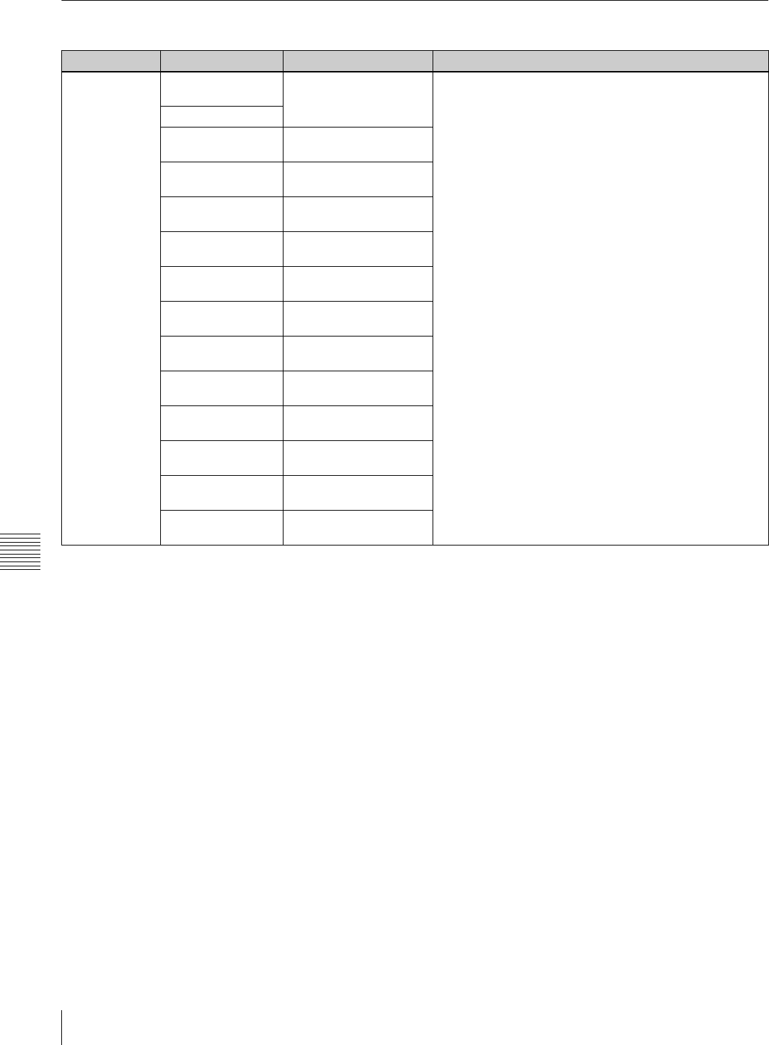
162 Menu List
Appendix
Items Relating to the Audio Control (Nos. 807 to ...)
Item number Item Setting Function
807 AUDIO MONITOR-L
select
Selects the audio channel output from the MONITOR
OUTPUT L connector.
Sub items
A-MON CH1 disable
[enable]
A-MON CH2 [disable]
enable
A-MON CH3 [disable]
enable
A-MON CH4 [disable]
enable
A-MON CH5 [disable]
enable
A-MON CH6 [disable]
enable
A-MON CH7 [disable]
enable
A-MON CH8 [disable]
enable
A-MON CH9 [disable]
enable
A-MON CH10 [disable]
enable
A-MON CH11 [disable]
enable
A-MON CH12 [disable]
enable

163
Menu List
Appendix
808 AUDIO MONITOR-R
select
Selects the audio channel output from the MONITOR
OUTPUT R connector.
Sub items
A-MON CH1 [disable]
enable
A-MON CH2 disable
[enable]
A-MON CH3 [disable]
enable
A-MON CH4 [disable]
enable
A-MON CH5 [disable]
enable
A-MON CH6 [disable]
enable
A-MON CH7 [disable]
enable
A-MON CH8 [disable]
enable
A-MON CH9 [disable]
enable
A-MON CH10 [disable]
enable
A-MON CH11 [disable]
enable
A-MON CH12 [disable]
enable
809 DIGITAL JOG
SOUND
[on]
off
Switches digital jog sound on or off.
off: Digital jog sound is off. In this case, the audio from the
digital channels is output, even in STILL mode, without
speed correction processing
on: Digital jog sound is on.
811 DIGITAL AUDIO
FADE TIME
5 ms
[10 ms]
15 ms
20 ms
25 ms a)
50 ms b)
85 ms
115 ms c)
Specifies the fade processing time during cross-fading or
fading-in/out of digital audio signals.
Note
Processing for cross fading, fading-in, and fading-out starts
after an IN or OUT point. This item specifies rewriting
during recording following the OUT point. Rewriting of one
field occurs even when the minimum setting (5 ms) is
selected. When “cut edit” is selected in item 317 to prevent
this from happening, a discontinuity in the audio signal
occurs. There is, however, no effect on the recording of the
video signal.
a) The cross-fade time is 24 ms.
b) The actual fade time is 49 ms.
c) The actual fade time is 114 ms.
813 AUDIO MONITOR
OUTPUT MIXING
add
[rms]
average
Specifies the type of audio mixing to be conducted on the
digital audio signal output to the MONITOR OUTPUT L/R
connector.
add: Simple addition
rms: Multiplied average
average: Simple average
Note
When the CUE channel signal is output to the monitor,
signals are mixed by simple addition.
Item number Item Setting Function

164 Menu List
Appendix
814 LEVEL METER
SCALE
[peak 0 dB]
reference 0 dB
Specifies the mode in which the digital audio level is
displayed.
peak 0 dB: Displays minus audio levels with the maximum
level set at 0 dB.
reference 0 dB: Displays plus and minus audio levels with
the reference level set at 0 dB.
Note
The CUE channel level is always displayed with the
reference level set at 0 dB.
815 AUDIO OUTPUT
PHASE
preset: 128
0
[128]
255
Sets the output timing for the digital audio playback signal
(SDI and AES/EBU only). The 128 setting specifies the
reference position.
A setting lower than 128 advances the output timing, and a
setting higher than 128 delays the output timing.
(128 samples, or approx. 2.7 ms, with 1 sample = approx.
20 µs)
816 PITCH
CORRECTION
[off]
on
Selects whether or not to perform pitch correction during
program play and play at a different frequency (23.98 frame
y 24 frame, 23.98/24 frame y 25 frame, 29.97 frame
y 30 frame).
off: Output audio with no pitch correction.
on: Output audio with pitch correction.
Item number Item Setting Function

165
Menu List
Appendix
817 PITCH
CORRECTION
GROUP select
When pitch correction is performed during program play
and play at a different frequency (23.98 frame y 24
frame, 23.98/24 frame y 25 frame, 29.97 frame y 30
frame), selects the group relationship between audio
channels.
Grp-A: Performs pitch correction according to the mutual
relationships between the channels selected for group
A.
Grp-B: Performs pitch correction according to the mutual
relationships between the channels selected for group
B.
Grp-C: Performs pitch correction according to the mutual
relationships between the channels selected for group
C.
Grp-D: Performs pitch correction according to the mutual
relationships between the channels selected for group
D.
Grp-E: Performs pitch correction according to the mutual
relationships between the channels selected for group
E.
Grp-F: Performs pitch correction according to the mutual
relationships between the channels selected for group
F.
OFF: Does not perform pitch correction for the channels
selected for group OFF.
Sub items
PITCH
CORRECTION
GROUP select CH1
[Grp-A] Grp-B Grp-C
Grp-D Grp-E Grp-F OFF
PITCH
CORRECTION
GROUP select CH2
[Grp-A] Grp-B Grp-C
Grp-D Grp-E Grp-F OFF
PITCH
CORRECTION
GROUP select CH3
Grp-A [Grp-B] Grp-C
Grp-D Grp-E Grp-F OFF
PITCH
CORRECTION
GROUP select CH4
Grp-A [Grp-B] Grp-C
Grp-D Grp-E Grp-F OFF
PITCH
CORRECTION
GROUP select CH5
Grp-A Grp-B [Grp-C]
Grp-D Grp-E Grp-F OFF
PITCH
CORRECTION
GROUP select CH6
Grp-A Grp-B [Grp-C]
Grp-D Grp-E Grp-F OFF
PITCH
CORRECTION
GROUP select CH7
Grp-A Grp-B Grp-C
[Grp-D] Grp-E Grp-F OFF
PITCH
CORRECTION
GROUP select CH8
Grp-A Grp-B Grp-C
[Grp-D] Grp-E Grp-F OFF
PITCH
CORRECTION
GROUP select CH9
Grp-A Grp-B Grp-C
Grp-D [Grp-E] Grp-F OFF
PITCH
CORRECTION
GROUP select
CH10
Grp-A Grp-B Grp-C
Grp-D [Grp-E] Grp-F OFF
PITCH
CORRECTION
GROUP select
CH11
Grp-A Grp-B Grp-C
Grp-D Grp-E [Grp-F] OFF
PITCH
CORRECTION
GROUP select
CH12
Grp-A Grp-B Grp-C
Grp-D Grp-E [Grp-F] OFF
Item number Item Setting Function

166 Menu List
Appendix
818 PITCH
CORRECTION
DETECT MODE
select
[Mode1]
Mode2
Mode3
OFF
When pitch correction is performed during program play
and play at a different frequency (23.98 frame y 24
frame, 23.98/24 frame y 25 frame, 29.97 frame y 30
frame), selects the pitch correction method for each group.
Mode1: Perform pitch correction using zero-cross jump.
Mode2: Perform pitch correction using zero-cross jump
after low-level detection.
Mode3: Perform pitch correction using cross fade.
OFF: Do not perform pitch correction.
Sub items
PITCH
CORRECTION
DETECT MODE
select Group-A
PITCH
CORRECTION
DETECT MODE
select Group-B
PITCH
CORRECTION
DETECT MODE
select Group-C
PITCH
CORRECTION
DETECT MODE
select Group-D
PITCH
CORRECTION
DETECT MODE
select Group-E
PITCH
CORRECTION
DETECT MODE
select Group-F
830 AUDIO INPUT
SELECT
AES/EBU
[SDI]
Selects the input signals for audio channels 1 to 12. This is
only valid when item 831 is set to “off”.
AES/EBU: Selects signal input to DIGITAL I/O (AES/EBU)
INPUT connector.
SDI: Selects signal input to HD SDI INPUT A connector.
A-IN ALL (sub item): Sets the items A-IN CH1 to CH12 to
the same value.
Sub items
A-IN ALL
A-IN CH1
A-IN CH2
A-IN CH3
A-IN CH4
A-IN CH5
A-IN CH6
A-IN CH7
A-IN CH8
A-IN CH9
A-IN CH10
A-IN CH11
A-IN CH12
Item number Item Setting Function

167
Menu List
Appendix
831 NON AUDIO
SELECT
AES/EBU
SDI
[off]
Selects a non-audio input signal. The setting is in units of
stereo pairs. When this is set to other than “off”, the setting
of item 830 is invalid.
AES/EBU: Selects signal input to DIGITAL I/O (AES/EBU)
INPUT connector as a data input.
SDI: Selects signal input to HD SDI INPUT A connector as
a data input.
off: Treats input as audio. Select the input signal with item
830.
Sub items
CH1/2
CH3/4
CH5/6
CH7/8
CH9/10
CH11/12
HDCAM REC
MODE(SRW-5500
only)
[BURST DATA MODE]
CONTINUOS MODE
Selects the format when non-audio data is to be recorded
on an HDCAM tape.
BURST DATA MODE: Select this to record data
compressed in video frame units (Dolby E, etc.).
CONTINUOS MODE: Select this to record data
compressed without reference to video frames (Dolby
Digital (AC-3), etc.).
832 AUDIO REC LEVEL FFFF (HEX)
[4000 $HEX%]
0 (HEX)
Sets the recording level.
Sub items
A-REC LEVEL CH1
A-REC LEVEL CH2
A-REC LEVEL CH3
A-REC LEVEL CH4
A-REC LEVEL CH5
A-REC LEVEL CH6
A-REC LEVEL CH7
A-REC LEVEL CH8
A-REC LEVEL CH9
A-REC LEVEL
CH10
A-REC LEVEL
CH11
A-REC LEVEL
CH12
A-REC LEVEL CUE
(SRW-5500 only)
Item number Item Setting Function

168 Menu List
Appendix
833 AUDIO PB LEVEL FFFF (HEX)
[4000 $HEX%]
0 (HEX)
Sets the audio playback level.
Sub items
A-PB LEVEL CH1
A-PB LEVEL CH2
A-PB LEVEL CH3
A-PB LEVEL CH4
A-PB LEVEL CH5
A-PB LEVEL CH6
A-PB LEVEL CH7
A-PB LEVEL CH8
A-PB LEVEL CH9
A-PB LEVEL CH10
A-PB LEVEL CH11
A-PB LEVEL CH12
A-PB LEVEL CUE
Item number Item Setting Function

169
Menu List
Appendix
834 DIGITAL AUDIO
OUTPUT
EXCHANGE
Specifies the audio multiplexed with HD SDI output, and the
signal tracks to be output to AES/EBU format audio output
channels 1 to 12.
Note that SD SDI also follows these settings when SDOUT
EXCHNG is set to dis (disable).
Sub items
DIGITAL OUT CH1 [TR1]
TR12
DIGITAL OUT CH2 TR1
[TR2]
TR12
DIGITAL OUT CH3 TR1
[TR3]
TR12
DIGITAL OUT CH4 TR1
[TR4]
TR12
DIGITAL OUT CH5 TR1
[TR5]
TR12
DIGITAL OUT CH6 TR1
[TR6]
TR12
DIGITAL OUT CH7 TR1
[TR7]
TR12
DIGITAL OUT CH8 TR1
[TR8]
TR12
DIGITAL OUT CH9 TR1
[TR9]
TR12
DIGITAL OUT CH10 TR1
[TR10]
TR12
DIGITAL OUT CH11 TR1
[TR11]
TR12
Item number Item Setting Function

170 Menu List
Appendix
DIGITAL OUT CH12 TR1
[TR12]
835 ANALOG AUDIO
OUTPUT
EXCHANGE
Sets the signal track to be superimposed on the analog
audio signal output channels 1 to 4.
Sub items
ANALOG OUT CH1 [TR1]
TR12
ANALOG OUT CH2 TR1
[TR2]
TR12
ANALOG OUT CH3 TR1
[TR3]
TR12
ANALOG OUT CH4 TR1
[TR4]
TR12
Item number Item Setting Function

171
Menu List
Appendix
836 SD AUDIO
OUTPUT
EXCHANGE
Makes independent track selections for the audio (channels
1 to 8) to be multiplexed into SD SDI.
Sub items
SDOUT EXCG [disable]
enable
disable: Follow the settings of DIGOUT EXCHNG menu
CH1 to CH8.
enable: Enable the settings of this menu.
SD OUT CH1 [TR1]
TR12
Specifies the signal tracks to assign to audio channels 1 to
8 for multiplexing with SD SDI output.
SD OUT CH2 TR1
[TR2]
TR12
SD OUT CH3 TR1
[TR3]
TR12
SD OUT CH4 TR1
[TR4]
TR12
SD OUT CH5 TR1
[TR5]
TR12
SD OUT CH6 TR1
[TR6]
TR12
SD OUT CH7 TR1
[TR7]
TR12
SD OUT CH8 TR1
[TR8]
TR12
Item number Item Setting Function

172 Menu List
Appendix
Items Relating to Digital Processing (Nos. 902 to ...)
Item number Item Setting Function
902 FREEZE MODE [field]
field1
field2
frame1+2
frame2+1
Specifies the freeze (still-picture) mode and freeze timing
during manual freezing (by REMOTE 1-IN(9P) or REMOTE
2 PARALELL I/O(50P) connector or on the control panel) or
automatic freezing.
field: Freezes the odd or even field, depending on the
timing in freeze mode.
field1: Freezes the first (odd) field
field2: Freezes the second (even) field
frame1+2: Freezes the first and the subsequent second
field
frame2+1: Freezes the second field and the subsequent
first field
In the case of freezing in playback modes other than
normal playback, the picture is frozen in frame mode only
when dynamic tracking is performing a frame operation.
The picture is frozed in field mode when dynamic tracking is
not operating.
The frozen picture does not change even if you change this
setting during freeze mode. The change to this setting
becomes effective the next time the VTR outputs a still
picture.
When the stop freeze function is enabled, regardless of the
setting of this item, the picture is frozen in frame mode only
when dynamic tracking is performing a frame operation, or
is frozen in field mode when dynamic tracking is performing
a field operation or when it is not operating.
903 FREEZE CONTROL
FROM KEY PANEL
[momentary]
latch
Determines the freeze operation control by button
operations.
momentary: The picture is frozen only while the button is
held down.
latch: The picture is frozen when the button is pressed, and
remains frozen when the button is released.
The fozen picture is cancelled when the button is pressed
again.
Button operations
Freezing in odd or even (first or second) field is specified
by item 902. Distinction between the first or second field,
follows the distinction in the reference signal.
905 STOP FREEZE
CONTROL
disable
[enable]
Enable or disables the stop freeze function.
910 ACTIVE LINE 1035
CONVERT MODE 1080k1035(CROP)
Selects the conversion mode of the effective scanning line
number.
1080k1035(CONV): Convert the effective scanning line
number from 1080 to 1035 preserving the aspect ratio
of the image.
1080k1035(CROP): Convert the effective scanning line
number from 1080 to 1035. The four sides of the image
are cropped, then it is horizontally expanded.
911 ACTIVE LINE 1080
CONVERT MODE 1035k1080(PANEL)
Selects the conversion mode of the effective scanning line
number.
1035k1080(CONV): Convert the effective scanning line
number from 1035 to 1080 preserving the aspect ratio
of the image.
1035k1080(PANEL): Convert the effective scanning line
number from 1035 to 1080. The 1035 lines of the
image are inserted into the 1035 lines of 1080 lines,
then it is horizontally compressed.
[1080 1035 $CONV%]
k
[1080 1035 $CONV%]
k

173
Menu List
Appendix
912 SLOW PROCESS
MODE
on
[off]
Selects whether or not to activate the function to improve
the vertical resolution during slow-motion playback.
on: Activate the function to improve the vertical resolution
during slow-motion playback.
off: Do not activate the function to improve the vertical
resolution during slow-motion playback.
Note
This setting has no effect when the VTR is operated in PsF
mode.
913 SOFT BLANKING [off]
on
This process applies a graduation to the first two and last
two samples of each horizontal scan line of the video
signal, thus making the join in the horizontal blanking
interval smoother.
on: The first two samples in the video data region are
increased gradually, and the last two samples are
decreased gradually.
off: The values of the entire video data region are displayed
unaltered.
921 ASPECT FLAG OFF [off]
on
Adds 16:9/Squeeze identification signal specified by ARIB
TR-B17 to down-converted SD output.
on: Add 16:9/Squeeze identification signal to down-
converted SD output.
off: Do not add 16:9/Squeeze identification signal to down-
converted SD output.
930
DOWNCONVERTER
MODE (DC)
[EDGE-CROP]
LETTER BOX
SQUEEZE
Selects the down converter mode.
EDGE-CROP: Selects edge crop mode.
LETTER BOX: Selects letter box mode.
SQUEEZE: Selects squeeze mode.
931 LETTER BOX
MODE (DC)
[16:9]
14:9
13:9
When item 930 is set to “LETTER BOX”, this setting
specifies the aspect ratio of the HD-SD converter output.
16:9: The aspect ratio of the HD-SD converter output is
16:9.
14:9: The aspect ratio of the HD-SD converter output is
14:9.
13:9: The aspect ratio of the HD-SD converter output is
13:9.
932 H CROP
POSITION
(DC)
preset: 0
–120
[0]
120
When item 930 is set to “EDGE-CROP,” adjusts the down-
converted output H crop (horizontal direction of portion cut
out in edge crop mode).
934 CROSS COLOR
(DC)
preset: 8
0
[8]
15
Cross color adjustment.
935 DETAIL GAIN (DC)
preset: 64
0
[64] (0 dB)
127
Adjustment of the down converter image enhancer,
adjusting the sharpness of enhanced contours.
936 LIMITER (DC)
preset: 32
0
[32]
63
Adjustment of the down converter image enhancer,
adjusting the maximum detail level to be added to enhance
the previous signal.
Item number Item Setting Function

174 Menu List
Appendix
937 CRISP
THRESHOLD
(DC)
preset: 0
[0]
15
Adjustment of the down converter image enhancer, and
setting an amplitude so that low amplitude signals are not
enhanced.
938 LEVEL DEPEND
THRESHOLD (DC)
Adjustment of the down converter image enhancer, and
setting the brightness range of enhanced contours.
Sub items
DEPEND BLACK
(DC)
0
[8]
15
DEPEND WHITE
(DC)
[0]
15
939 H DETAIL
FREQUENCY
select (DC)
2.6 MHz
3.4 MHz
[4.3 MHz]
6.7 MHz
Adjustment of the down converter image enhancer, and
setting the central frequency for enhanced contours.
940 H/V RATIO (DC)
preset: 3
0
[3]
7
Adjustment of the down converter image enhancer, and
setting the horizontal to vertical ratio for enhanced
contours.
941 GAMMA (DC) [on]
off
Activates or deactivates the GAMMA LEVEL setting by the
item 941.
942 GAMMA LEVEL
(DC)
preset: 0
128
[0]
–128
Adjustment of the down converter image enhancer, and
setting the slope of the correction curve.
Valid only when the GAMMA LEVEL setting is activated by
the menu item 941.
943 CROSS COLOR
CRISP (DC)
preset: 4
0
[4]
15
Sets the crisp level for down converter output cross color.
944 V-FILTER SELECT [mode 0]
mode 1
mode 2
mode 3
Sets the vertical interpolation filter coefficient for HD-SD
converter output.
950 CONVERTER
MODE (UC)
[EDGE-CROP]
LETTER BOX
SQUEEZE
Selects the mode for up conversion.
EDGE-CROP: Select edge crop mode.
LETTER BOX: Select letterbox mode.
SQUEEZE: Select squeeze mode.
951 H CROP POSITION
(UC)
preset: 0
–120
[0]
120
When “EDGE-CROP” is selected in menu item 950, adjusts
the H crop (the frame in the horizontal direction inserted in
edge crop mode) in up-conversion output.
952 LETTER BOX
POSITION (UC)
preset: 0
–120
[0]
120
When “LETTER BOX” is selected in menu item 950, adjusts
the position in the vertical direction of the “letterbox” in up-
conversion output.
Item number Item Setting Function

175
Menu List
Appendix
953 UP CONVERTER
PROCESS
FIELD
FRAME
[ADAPTIVE]
ADAPTIVE-2
ADAPTIVE-3
Selects the original image used for conversion from SD to
HD.
FIELD: Selects field images.
FRAME: Selects frame images.
ADAPTIVE (standard mode): For up-conversion, the mode
in which the ratio of carrying out conversion from
frames or fields is set to the standard value.
ADAPTIVE-2 (still image priority mode): For up-conversion,
the mode in which the ratio of carrying out conversion
from frames is increased.
ADAPTIVE-3 (movie priority mode): For up-conversion, the
mode in which the ratio of carrying out conversion from
fields is increased.
954 DETAIL GAIN (UC)
preset: 64
0
[64]
127
Adjusts the up converter image enhancer.
Adjusts the sharpness of outlines.
955 LIMITTER (UC)
preset: 32
0
[32]
63
Adjusts the up converter image enhancer.
Adjusts the detail maximum level added to emphasize the
original signal.
956 CRISP
THRESHOLD (UC)
preset: 8
0
[8]
15
Adjusts the up converter image enhancer.
Sets the amplitude value for which small amplitude signals
are not emphasized.
957 LEVEL DEPEND
THRESHOLD (UC)
preset: 8
0
[8]
15
Adjusts the up converter image enhancer.
Sets the luminance range for edge enhancement.
958 H DETAIL
FREQUENCY (UC)
3.2MHz
4.5MHz
[5.0MHz]
4.0MHz
Adjusts the up converter image enhancer.
Sets the central frequency and frequency characteristics for
edge enhancement.
3.2MHz: 3.2 MHz ±1.1 MHz
4.5MHz: 4.5 MHz ±1.4 MHz
5.0MHz: 5.0 MHz ±0.7 MHz
4.0MHz: 4.0 MHz ±2.0 MHz
959 H/V RATIO (UC)
preset: 3
0
[3]
7
Adjusts the up converter image enhancer.
Sets the vertical to horizontal ratio for edge enhancement.
960 GAMMA LEVEL
(UC)
preset: 0
128
[0]
–120
Adjusts the up converter image enhancer.
Adjusts the gradient of the correction curve.
961 BACKGROUND
COLOR (UC)
BACKGROUND COLOR
[0] to FFH
0 to [80] to FFH
0 to [80] to FFH
Sets the background color for blank areas in up conversion.
BACKGROUND COLOR: Sets the color.
BG COLOR: Selects TABLE/GRAY/BLUE/BLACK.
Y, R-Y, B-Y: Valid only when BG COLOR is set to “TABLE”.
Adjustable within the range from 0 to FFH.
Sub items
BG COLOR
Y TABLE
R-Y TABLE
B-Y TABLE
Item number Item Setting Function

176 Menu List
Appendix
Stop freeze operation
• A “DT picture” is a frozen picture in noiseless DT playback mode. The
picture freezes in frame mode when the dynamic tracking is performing a
frame operation. It freezes in field mode when dynamic tracking is not
performing a frame operation.
• A “non-DT picture” is a frozen picture in shuttle mode. A block pattern
may appear in a non-DT picture, depending on the circumstances.
Items Relating to the Pulldown Control (Nos. A01 to ...)
980 ALPHA CHANNEL
LEVEL
white
[black]
For 4:4:4 DUAL LINK output, sets the output level of the
ALPHA CHANNEL of LINK B output.
white: Output white level.
black: Output black level.
MODE (After) STOP TENSION OFF STDBY OFF
MODE (Before)
STILL (dynamic tracking on) DT picture DT picture DT picture
CAPSTAN drive (includes shuttling up to ×10 normal tape speed) non-DT picture non-DT picture non-DT picture
Reel drive (includes shuttling over ×10 normal tape speed) non-DT picture non-DT picture non-DT picture
Item number Item Setting Function
Item number Item Setting Function
A01 PD TIME CODE
DISPLAY
[off]
on
Sets whether or not to display the pulldown time code on
the time code display area.
off: Does not display the pulldown time code.
on: Displays the pulldown time code.
A02 PD PRESET
FRAME MODE
[24F FRAME MODE]
30F FRAME MODE
Selects the time code to be preset. The A frame of the
pulldown sequence can be preset.
24F FRAME MODE: The 24 frames time code is preset.
30F FRAME MODE: The 30 frames time code is preset.
A03 FC
SUPERIMPOSED
CHARACTER
[off]
on
Specifies whether or not to superimpose time data and
operating status information on the signal output from the
FORMAT CONV. OUT connector.
off: No information is superimposed.
on: Information is superimposed.
A04 PD DF/NDF
SELECT
[drop frame]
non-drop frame
auto
Selects the running mode for the pulldown time code to be
preset.
drop frame: Drop frame mode
non-drop frame: Non-drop frame mode
auto: The unit switches the running mode (DF/NDF)
automatically according to the frame frequency of the
unit. When the frame frequency is 23.98 Hz, the unit
switches to the drop frame mode and switches to the
non-drop frame mode when it is 24 Hz.

177
Menu List
Appendix
A05 PD EXT SD REF
LOCK MODE
[off]
lock1
lock2
When the operating frequency is set to 23.98PsF, specifies
whether or not the pulldown output signal and down-
converted output signal are synchronized with the
reference signal by the REF. INPUT 2 connector.
off: The pulldown output signal and down-converted output
signal are not synchronized with the reference signal
by the REF. INPUT. 2 connector.
lock1: The pulldown output signal and down-converted
output signal are synchronized with the reference
signal by the REF. INPUT 2 connector.
lock2: The pulldown output signal and down-converted
output signal are synchronized with the reference
signal by the REF. INPUT 2 connector. When the PB/
EE mode is selected, the amount of delay on the A
frame of the pulldown output signal for the A frame of
the main video signal is fixed to 2 frames (59.94i).
Notes
• A warning message appears when the HD reference
signal and REF. INPUT 2 reference signal are not input or
not synchronized.
• “lock1” and “lock2” are effective only when the operation
mode of this unit is set to 23.98/24PsF.
• When editing in 23.98/24PsF mode, with this unit as the
recorder and with “lock2” selected, phase
synchronization may not be achieved within 5 seconds.
Also, edit In points may be out of alignment. In these
cases, select “off”.
A06 PD
SUPERIMPOSED
TIME CODE ID
[off]
on
When item 620 and A03 is set to “on”, specifies whether or
not the ID (24F/30F) is displayed to the right of
superimposed time code.
off: No ID is displayed.
on: ID (“24F” or “30F”) is displayed.
Note
The setting of this item is effective only when the operation
mode of this unit is set to 23.98PsF or 24PsF.
A07 PD CHARACTER
24F TIME CODE
MODE
[off]
on
When item 620 and A03 is set to “on”, specifies whether or
not the 2 : 3 pulldown 24-frame time data is inserted to the
first line instead of 30-frame time data.
off: 30-frame time data is displayed.
on: 24-frame time data is displayed.
Note
The setting of this item is effective only when the operation
mode of this unit is set to 23.98PsF or 24PsF.
A08 FC REFERENCE
select
extrn HD
[extrn SD]
Selects the signal to be the reference for the FORMAT
CONV. OUT input to the REF. INPUT 2 connector.
extrn HD: Use the HD tri-level reference signal input to the
REF. INPUT 2 connector as the FORMAT CONV. OUT
reference signal.
extrn SD: Use the SD reference signal input to the REF.
INPUT 2 connector as the FORMAT CONV. OUT
reference signal.
Item number Item Setting Function
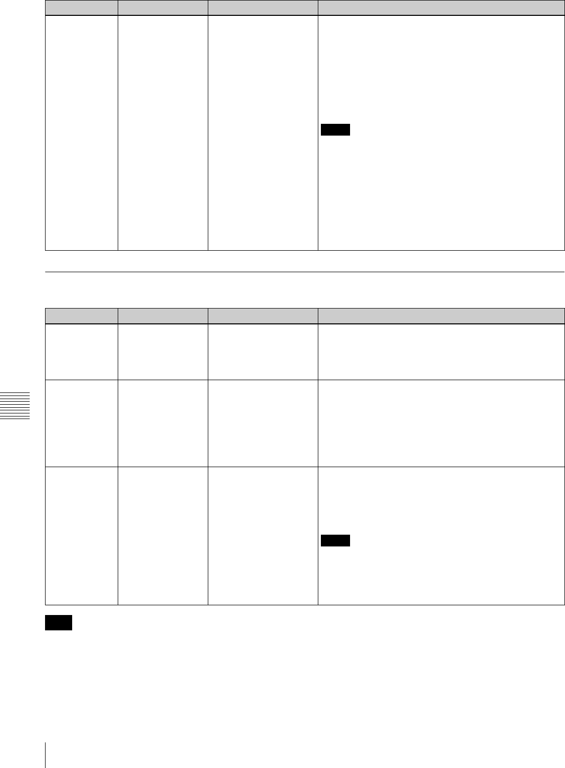
178 Menu List
Appendix
Other Items (Nos. T01 to ...)
Items T01, T02, and T04 are reset to their factory default
settings whenever the power is turned off.
A10 TC sense data
select
[LINE/24F]
FC/30F
Specifies whether or not the time code information of FC
output signal is returned when time code sense command
is input through the 9-pin connector.
LINE/24F: Time code information of main output signal is
returned. In pulldown conversion mode, 24-frame/sec
time code information is returned.
FC/30F: Time code information of FC output signal is
returned. In pulldown conversion mode, 30-frame/sec
time code is returned.
Notes
• Pulldown output signal and 30-frame/sec time code are
synchronized only when this unit is set to PLAY LOCK
mode. To synchronize the signals, set item A05 “PD EXT
SD REF LOCK MODE” to “lock2”.
• When editing pulldown output signals with a VTR
operating in 30F mode, it may not be possible to achieve
sync within 5 seconds. If this occurs, set the preroll time
to 7 seconds.
Also, normal operation is not possible with devices
engaged in player sync.
Item number Item Setting Function
T01 AUTO REPEAT
MODE
[off]
on
Selects the repeating operation of PREVIEW in automatic
editing.
off: PREVIEW in automatic editing is not repeated.
on: PREVIEW in automatic editing is repeated. To stop,
press the STOP button.
T02 INTERNAL VIDEO
SIGNAL
GENERATOR (HD)
[off]
COLOR BARS
MULTI BURST 1
MULTI BURST 2
10 STEPS
PULSE & BAR
RAMP
BLACK
Selects the test signal output by the signal generator built
into the VTR.
off: The test signal is not generated, and the VTR operates
normally.
all other settings: The test signal is output from the VTR. At
this time it is also possible to record the signal.
T04 INTERNAL AUDIO
SIGNAL
GENERATOR
[off]
silence
1 kHz sine
Selects the operation of audio test signal output.
off: The audio test signal is not output.
silence: Mute signal.
1 kHz sine: 1 kHz (In this case, a 1 kHz -20 dB FS sine
wave is supplied to all audio inputs.)
Notes
• When “silence” or “1 kHz sine” is selected, the AUDIO IN
and AUDIO MONITOR L/R buttons light up.
• When the unit is operated in the 23.98 PsF or 24 PsF
mode with “1 kHz sine” selected, the output signal is
960 Hz.
Item number Item Setting Function
Note
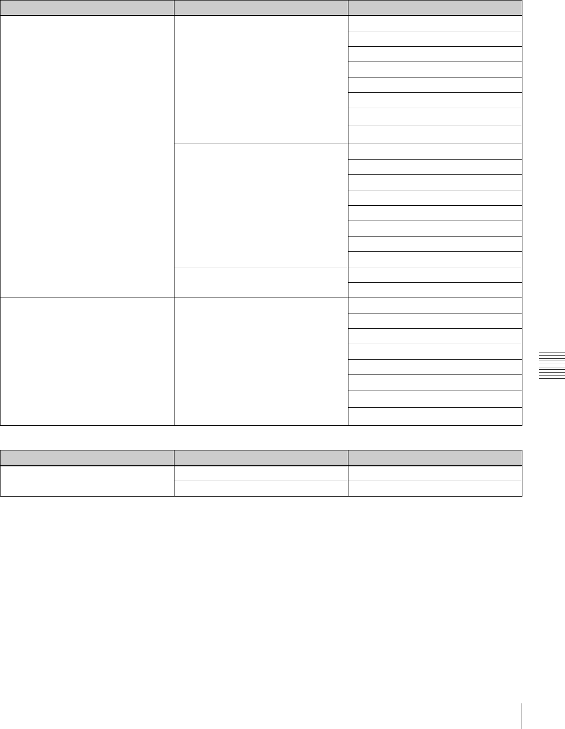
179
Menu List
Appendix
Recording and playback formats
Recording and playback formats:
Recording formats:
a) When the number of valid input signal lines is 1035, the system detects this
and automatically selects 1035 recording mode.
Cassette type Recording/playback mode System frequency
HDCAM-SR 1920 × 1080/4:2:2 23.98PsF
24PsF
25PsF
29.97PsF
30PsF
50i
59.94i a)
60i a)
1920 × 1080/4:4:4
(optional HKSR-5003 required)
23.98PsF
24PsF
25PsF
29.97PsF
30PsF
50i
59.94i
60i
1280 × 720/4:2:2 50P
59.94P
HDCAM
(playback only on SRW-5000) 1920 × 1080/4:2:2 23.98PsF
24PsF
25PsF
29.97PsF
30PsF
50i
59.94i a)
60i a)
Cassette type Playback mode System frequency
Digital Betacam
(optional HKSR-5002 required)
625/4:2:2 50i
525/4:2:2 59.94i
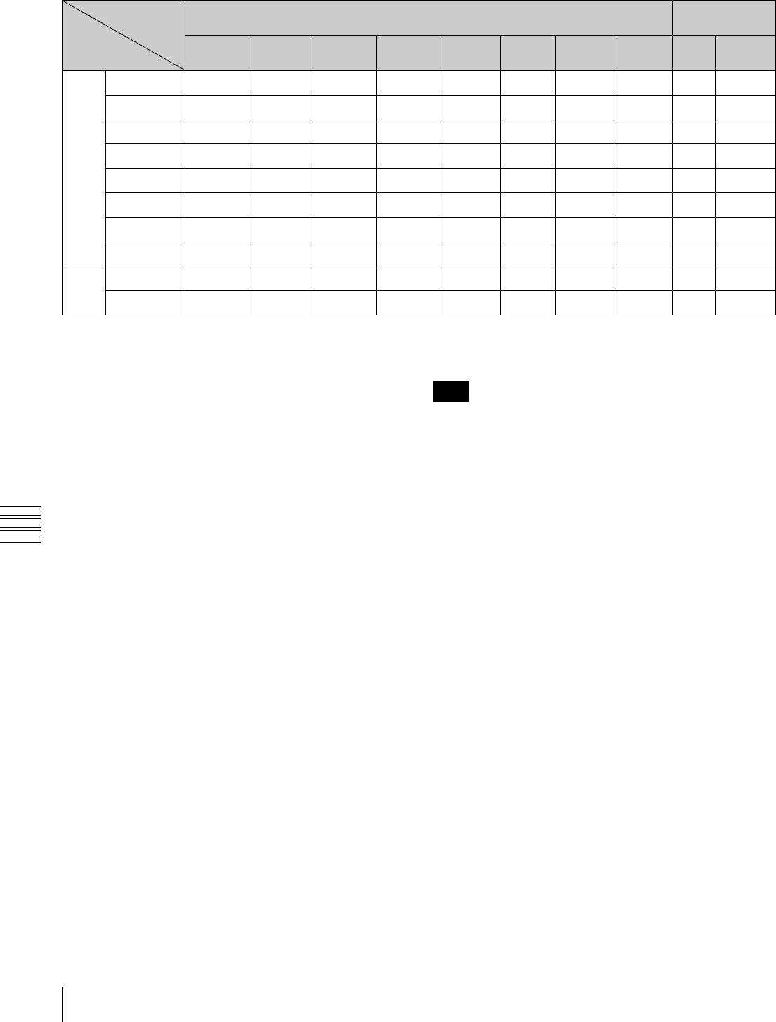
180 Menu List
Appendix
Recording tape format conversion outputs
a: Normal playback of video, audio, and time code possible.
z: 0.1% off-speed playback of video, audio, and time code possible.
f: Off-speed playback of video and audio possible. Time code playback and
time code conversion possible (differs depending on menu settings).
v: HDCAM-SR: Off-speed playback of video and audio possible. Time
code conversion possible (differs depending on menu settings. For
details, see menu item 630 on page158.).
HDCAM: Off-speed playback of video possible. Audio is muted, and
time code conversion possible (differs depending on menu settings. For
details, see menu item 630 on page 158.).
a) Output as PsF to HD SDI OUTPUT connectors.
b) Output as Interlaced to HD SDI OUTPUT connectors.
c) 720/59.94P or 720/50P is enabled only for HDCAM-SR.
Tapes with different sampling methods cannot be played
back (4:4:4/4:2:2).
System
frequency 1080 720
Recording
tape format
23.98PsF 24PsF 25PsF 29.97PsF 30PsF 50i 59.94i 60i 50P c) 59.94P c)
1080 23.98PsF azf v v
fa) va) va)
24PsF zaf v v
fa) va) va)
25PsF ffavv
aa) va) va)
29.97PsF vvvaz
va) aa) za)
30PsF vvvza
va) za) aa)
50i fb) fb) ab) vb) vavv
59.94i vb) vb) vb) ab) zvaz
60i vb) vb) vb) zb) avza
720 50P c) a
59.94P c) a
Note

181
Menu List
Appendix
Recording and playback tape formats and conversion output
a) Optional HKSR-5001 required.
b) Optional HKSR-5002 required.
c) Optional HKSR-5003 required.
d) When the system setting is 1080, only playback is possible.
e) When the system setting is 720, only playback is possible.
Cassette type Recording/playback
mode
HD SDI output SD output FC output a)
System frequency System frequency System frequency
HDCAM or HDCAM-SR 1080/4:2:2 23.98PsF 525/59.94i a) 1080/4:2:2/59.94i
720/4:2:2/59.94P
1080/4:4:4/23.98PsF
24PsF 1080/4:2:2/60i
1080/4:4:4/24PsF
25PsF 625/50i 720/4:2:2/50P
1080/4:4:4/25PsF
29.97PsF 525/59.94i 720/4:2:2/59.94P
1080/4:4:4/29.97PsF
30PsF 1080/4:4:4/30PsF
50i 625/50i 720/4:2:2/50P
1080/4:4:4/50i
59.94i 525/59.94i 720/4:2:2/59.94P
1080/4:4:4/59.94i
60i 1080/4:4:4/60i
1035/4:2:2 59.94i 525/59.94i
60i
HDCAM-SR 720/4:2:2 50P 625/50i 1080/4:2:2/50i
59.94P 525/59.94i 1080/4:2:2/59.94i
Digital Betacam b) 1080/4:2:2 d) 50i 625/50i 720/4:2:2/50P
720/4:2:2 e) 50P 625/50i 1080/4:2:2/50i
1080/4:2:2 d) 59.94i 525/59.94i 720/4:2:2/59.94P
720/4:2:2 e) 59.94P 525/59.94i 1080/4:2:2/59.94i
HDCAM-SR 1080/4:4:4 c) 23.98PsF 1080/4:2:2/23.98PsF
525/59.94i a) 1080/4:2:2/59.94i
720/4:2:2/59.94P
24PsF 1080/4:2:2/24PsF
1080/4:2:2/60i
25PsF 625/50i a) 1080/4:2:2/25PsF
720/4:2:2/50P
29.97PsF 525/59.94i a) 1080/4:2:2/29.97PsF
30PsF 1080/4:2:2/30PsF
50i 625/50i a) 1080/4:2:2/50i
720/4:2:2/50P
59.94i 525/59.94i
a) 1080/4:2:2/59.94i
720/4:4:4/59.94P
60i 1080/4:2:2/60i

182 Menu List
Appendix
Relation between HKDV-900/503 setting items and setup menu items of this unit
In the cells of the “Setup menu items of this unit”
column, the brackets indicate available outputs.
a) Select whether to set DC or UC with sub item “IMAGE ENHANCER” of
menu item 204 (VIDEO REMOTE CONTROL SELECT). When both are
selected (menu item 204 is U&D), both of the corresponding menu settings
are made, but this unit's answer values and unity values a re the DC values.
b) With the exception of composite output.
c) Use sub item “D2 SETUP” of menu item 204 “VIDEO REMOTE
CONTROL SELECT” to determine whether to control menu item 762
“SETUP LEVEL (CST)” or 743 “BLACK LEVEL (ALL)”.
d) When operating on the UC side, the setting of menu item 950
“CONVERTER MODE (UC)” automatically determines whether menu
item 951 “H CROP POSITION (UC)” or menu item 952 “LETTER BOX
POSITION (UC)” is used.
e) Supported by Sys1/Sys2/CP Ver. 2.70 or higher.
f) Supported by Sys1/Sys2/CP Ver. 3.00 or higher.
HD: HD SDI output during HDCAM-SR/HDCAM playback
DC: Down-converted SD (SD SDI/COMPOSITE) output during HDCAM-
SR/HDCAM format playback
SD: SD (D1 (SD SDI/COMPOSITE) output during Digital Betacam format
playback
UC: Upconverted HD SDI output during Digital Betacam format playback
FC: During Digital Betacam playback, up convert output from the optional
HKSR-5001 format converter
HKDV-900/503
setting items
Setup menu items of this unit
HD Master 708: MASTER LEVEL (HD) [HD/UC]
HD Y 709: Y LEVEL (HD) [HD/UC]
HD PB710: PB LEVEL (HD) [HD/UC]
HD PR711: PR LEVEL (HD) [HD/UC]
HD Setup 712: SETUP LEVEL (HD) [HD/UC]
HD Sync Phase 713: SYNC PHASE (HD) [HD/UC]
HD Fine 714: FINE (HD) [HD/UC]
D1 Master 755: MASTER LEVEL (D1) [DC/SD] b)
D1 Y 756: Y LEVEL (D1) [DC/SD] b)
D1 B–Y 757: B–Y LEVEL (D1) [DC/SD] b)
D1 R–Y 758: R–Y LEVEL (D1) [DC/SD] b)
D2 VIDEO 740: VIDEO GAIN (ALL) [HD/UC/SD/DC] e)
D2 CHROMA 741: CHROMA GAIN (ALL) [HD/UC/SD/DC] e)
D2 HUE 742: CHROMA PHASE (ALL) [HD/UC/SD/DC] e)
D2 SETUP 762: SETUP LEVEL (CST) [DC/SD] c)
743: BLACK LEVEL (ALL) [HD/UC/SD/DC] e), f)
SD Sync Phase 763: SYNC PHASE (SD) [DC/SD]
SD Fine 764: FINE (SD) [DC/SD]
CROSS COLOR 934: CROSS COLOR (DC) [DC]
H CROP POSITION 932: H CROP POSITION (DC) [DC] / 951: H CROP POSITION (UC) [UC/FC] a) /
952: LETTER BOX POSITION (UC) [UC/FC] d)
DETAIL GAIN 935: DETAIL GAIN (DC) [DC] / 954: DETAIL GAIN (UC) [UC/FC] a)
LIMITTER 936: LIMITTER (DC) [DC] / 955: LIMITTER (UC) [UC/FC] a)
CRISP 937: CRISP THRESHOLD (DC) [DC] / 956: CRISP THRESHOLD (UC) [UC/FC] a)
DEPEND 938: LEVEL DEPEND THRESHOLD (DC) [DC] / 957: LEVEL DEPEND THRESHOLD (UC) [UC/FC] a)
FREQUENCY 939: H DETAIL FREQUENCY select (DC) [DC]/ 958: H DETAIL FREQUENCY (UC) [UC/FC] a)
H/V RATIO 940: H/V RATIO (DC) [DC] / 959: H/V RATIO (UC) [UC/FC] a)
GAMMA 942: GAMMA LEVEL (DC) [DC] / 960: GAMMA LEVEL (UC) [UC/FC] a)
CROP 930: DOWNCONVERTER MODE (DC) [DC] / 950: CONVERTER MODE (UC) [UC/FC] a)
LETTER BOX 930: DOWNCONVERTER MODE (DC) [DC] / 950: CONVERTER MODE (UC) [UC/FC] a)
SQUEEZE 930: DOWNCONVERTER MODE (DC) [DC] / 950: CONVERTER MODE (UC) [UC/FC] a)

183
Index
Index
Index
A
AC IN connector 28
Adjusting
audio playback level 107
output video signal 88
Advanced Automatic Editing 126
ALT button 18
Assemble mode 115
AUDIO IN/OUT buttons 19
AUDIO Menu 91
AUDIO OUTPUT CH1 to CH4
connectors 25
AUTO button 19
Automatic edit modes 115
Automatic editing 115
animation editing 127
backspace editing 72
confirming edit points 120
cuing up and prerolling 121
DMC editing 126
Modifying edit points 122
Non-audio data 120
Overview 115
Preread editing 127
Previewing 121
Selecting the edit mode 117
Setting edit points 117
Setting switches and menus 116
Steps 115
B
Backspace editing 72
Basic Automatic Editing 115
C
Capstan override playback 111
Cassettes
handling cassettes 34
inserting and ejecting cassettes 34
preventing accidental erasure 35
recommended cassettes 34
Changing
menu settings 37
preroll time 121
CHANNEL CONDITION indicators
16
CLR button 19
Color display 18
Confirming edit points 120
Connecting external equipment 29
cascade connection 31
making HD digital connections
29
making NTSC/PAL Digital
Connections 30
Connector panel 24
ANALOG I/O section 25
DIGITAL I/O section 27
power supply 28
remote input/output section 28
Control panel 15
lower control panel (Display
section) 20
lower control panel (Editing
control section) 19
lower control panel (Menu control
section) 17
lower control panel (Search
control section) 22
lower control panel (System Set-
Up Panel) 23
lower control panel (Tape
transport control section)
20
upper control panel 16
CONTROL PANEL connector 23
CTL timer 59
CUE IN connector 26
CUE menu 68
CUE OUT connector 26
Cue point
erasing 71
prerolling 71
registering 69
Cursor buttons 19
Cut editing 151
D
Deleting edit points 122
DF (drop frame) mode 154
DIAG button 18
DIGITAL I/O INPUT connectors 27
DIGITAL I/O OUTPUT connectors
27
DISPLAY button 18
Display section 20
Displaying the duration 120
DMC editing 126
overview 126
performing 127
setting edit points and playback
speed 126
DMC playback 52
overview 111
E
Editing control section 19
Editing point
confirming 120
deleting 122
modifying 122
moving 122
setting 117, 119
Editing precautions 115
Effective scanning line number 172
EJECT button 16
Ejecting the cassette 35
Emphasis 139
ENTRY button 19
ERROR indicator 16
Error Log Menu
adjusting the clock 138
clearing warning messages 138
Error log menu 137
Error Messages 134
ETHERNET connector 28
EXTEND mode 152
F
Fade-in/out 120, 151
FC OUT B connectors 27
FORMAT CONV. OUT (OPTION)
connectors 27
Format indicators 16
FULL/FINE button 18
Function buttons 18
H
HD REF. OUT connectors 26
HD SDI INPUT A/B connectors 27
HD SDI OUTPUT connectors 27
HD-SD conversion mode
edge crop mode 108
letter box mode 108
squeeze mode 108
Head cleaning 130
HOME menu 50
I
IN/OUT buttons 19
Information display 20
INPUT CHECK button 19
Insert mode 115
J
JOG button 22
Jog mode playback 109
L
Lower control panel 17

184 Index
Index
M
Maintenance 130
Manual editing 129
Memory label 10, 11, 73
Memory stick
adding titles 46
data compatibility 47
formatting 41
operations 41
recalling 44
storing 42
storing cue point lists 43
Menu
changing a CUE point into an edit
point 72
configuration 37
control section 17
list 141
PANEL SETUP menu 100
PF1 menu 37
PF2 menu 37
registering items to the VTR
SETUP menu 38
selection buttons 17
Moisture condensation 130
MONITOR L buttons 17
MONITOR OUTPUT L/R connectors
25
MONITOR R buttons 17
Monitoring video and audio signals
being recorded 105
MULTI CONTROL knob 17
N
NDF (Non-drop frame) mode 154
Normal-speed playback 109
Numeric buttons and +/– buttons 19
O
Overview
automatic editing 115
DMC editing 126
DMC playback 111
P
PAGE mode 152
PANEL SETUP menu 100
Pausing the current time 60
PB LEVEL button 18
PCM CIA card slot 23
PF1 menu 11, 147
PF2 menu 11, 147
PHONES jack 17
PHONES level control 17
Pitch correction function 10
PLAY button 20
Playback 109
capstan override playback 111
DMC playback 111
jog mode playback 109
non-audio data 112
normal-speed playback 109
shuttle mode playback 110
variable mode playback 110
variable speed playback 109
PLAYER/RECORDER buttons 19
POWER switch 16
Preparing for playback 107
adjusting the audio playback level
107
improve the vertical resolution
173
selecting the HD-SD conversion
mode 108
selects the conversion mode of the
effective scanning line
number 172
setting switches and menus 107
Preparing for recording 102
adjusting the recording level 104
selecting audio signals 103
setting switches and menus 102
Preread editing 127
PREREAD indicator 21
PREROLL button 20
Preroll time setting 52
PREVIEW/REVIEW button 20
Program play function 10
Pulldown output 177
Pulldown time code
displaying 64
presetting 61
R
RCL button 19
REC INHIBIT indicator 22
REC LEVEL button 18
REC/EDIT button 20
Recording 106
inhibit mode 51
REF SYNC indicators 21
REF. INPUT 1 connectors 25
REF. INPUT 2 connectors 25
Reference signal connections 33
REMOTE 1-I/O connector 28
REMOTE 1-IN connector 28
REMOTE 2 PARALLEL I/O
connector 28
REMOTE buttons 16
RS232C connector 28
S
SD OUT COMPOSITE (MONITOR)
connector 26
SD OUT SYNC connector 25
SD SDI OUT connectors 27
Search control section 22
Search dial 22
Selecting
audio input signals 103
audio signals to be monitored 103
Conversion mode of the effective
scanning line number
172
CTL display mode 61
DMC playback 52
edit mode 51
HD-SD conversion mode 108
multi-cue mode 69
non-audio data as the audio input
signal 104
output signals 51
reference signal 32
remote operation mode 97
time code and the user bits to be
recorded 58
SERVO indicator 22
SET button 19
SET UP menu 97
SFT button 19
SHUTTLE button 22
Shuttle mode playback 110
Slow-motion playback
improve the vertical resolution
173
Specifications 131
Split editing 118
STANDBY button 20
STOP button 20
Superimposition of character
information 64
System set-up panel 23
T
Tape transport control section 20
TC menu 56
TELE FILE menu 72
Tele-File 10
Time code
presetting for conversion from
Frame time code 62
running mode 60
setting 60
time code generator (TCG
SOURCE/MODE) 60
TIME CODE IN connector 26
TIME CODE OUT connector 26

185
Index
Index
Time code reader (TCR) 60
Time data
resetting 59
selecting the time data display 57
setting 57
U
Upper control panel 16
USB connector 28
User bits setting 59
Using a Memory Stick 35
Using the CD-ROM manual 13
V
VAR button 22
Variable speed playback 109
VIDEO CONTROL connector 28
VIDEO Menu 87
VTR memory banks 39
adding titles 46
recalling 40
storing 39
VTR SETUP menu 98
items related to digital processing
172
items related to editing 149
items related to operation panels
145
items related to prerolling 152
items related to recording
protection 153
items related to remote interface
148
items related to the audio control
162
items related to the pulldown
control 176
items related to the time code 154
items related to the video control
158
items related to VTR operations
141
Other items 178
W
WARNING indicator 16
Warning messages 135
The material contained in this manual consists of information
that is the property of Sony Corporation and is intended solely
for use by the purchasers of the equipment described in this
manual.
Sony Corporation expressly prohibits the duplication of any
portion of this manual or the use thereof for any purpose
other than the operation or maintenance of the equipment
described in this manual without the express written
permission of Sony Corporation.
Trademarks
• Intel and Pentium are registered trademarks of Intel
Corporation or its subsidiaries in the United States and other
countries.
• Microsoft and Windows are registered trademarks of
Microsoft Corporation in the United States and/or other
countries.
• Adobe, Acrobat, and Adobe Reader are trademarks of
Adobe Systems Incorporated in the United States and/or
other countries.

Sony Corporation
SRW-5000/5500
(SY)
3-792-075-05 (1) © 2003
