Sony Cinealta Pdw F330K Users Manual F330L/F330K/F350L
PDW-F330K to the manual 15a6a6fc-02ca-40ce-bcf4-f1e24b357d8e
2015-01-24
: Sony Sony-Cinealta-Pdw-F330K-Users-Manual-285920 sony-cinealta-pdw-f330k-users-manual-285920 sony pdf
Open the PDF directly: View PDF ![]() .
.
Page Count: 188 [warning: Documents this large are best viewed by clicking the View PDF Link!]

3-990-971-12(1)
Professional Disc
Camcorder
Operating Instructions
Before operating the unit, please read this manual
thoroughly and retain it for future reference.
PDW-F330L
PDW-F330K
PDW-F350L
© 2006 Sony Corporation

2
Owner’s Record
The model and serial numbers are located on the top.
Record these numbers in the spaces provided below. Refer
to them whenever you call upon your Sony dealer
regarding this product.
Model No. Serial No.
To reduce the risk of fire or electric shock,
do not expose this apparatus to rain or
moisture.
To avoid electrical shock, do not open the
cabinet. Refer servicing to qualified
personnel only.
This Professional Disc Camcorder is classified as a CLASS 1
LASER PRODUCT.
Laser diode properties
Wavelength: 403 to 410 nm
Emission duration: Continuous
Laser output power: 65 mW (max. of pulse peak), 35 mW
(max. of CW)
Tekniska data för laserdiod
Våglängd: 403 till 410 nm
Emissionslängd: Kontinuerlig
Laseruteffekt: 65 mW (max. för pulstopp), 35 mW (max. för
kontinuerlig våg)
Spesifikasjoner laserdiode
Bølgelengde: 403 til 410 nm
Strålingens varighet: Kontinuerlig
Laserens effekt: 65 mW (maks stråletoppunkt), 35 mW
(maks ved kontinuerlig stråling)
Laserdiodin ominaisuudet
Aallon pituus: 403 - 410 nm
Välityksen kesto: Jatkuva
Laserlähdön teho: 65 mW (sykehuipun maks.), 35 mW
(jatkuvan aallon maks.)
CAUTION
The use of optical instruments with this product will increase
eye hazard.
CAUTION
Use of controls or adjustments or performance of procedures
other than those specified herein may result in hazardous
radiation exposure.
VAROITUS!
LAITTEEN KÄYTTÄMINEN MUULLA KUIN TÄSSÄ
KÄYTTÖOHJEESSA MAINITULLA TAVALLA SAATTAA
ALTISTAA KÄYTTÄJÄN TURVALLISUUSLUOKAN 1
YLITTÄVÄLLE NÄKYMÄTTÖMÄLLE LASERSÄTEILYLLE.
VARNING
OM APPARATEN ANVÄNDS PÅ ANNAT SÄTT ÄN I DENNA
BRUKSANVISNING SPECIFICERATS, KAN ANVÄNDAREN
UTSÄTTAS FÖR OSYNLIG LASERSTRÅLNING, SOM
ÖVERSKRIDER GRÄNSEN FÖR LASERKLASS 1.
For the customers in the U.S.A.
This equipment has been tested and found to comply with the
limits for a Class A digital device, pursuant to Part 15 of the
FCC Rules. These limits are designed to provide reasonable
protection against harmful interference when the equipment is
operated in a commercial environment. This equipment
generates, uses, and can radiate radio frequency energy and,
if not installed and used in accordance with the instruction
manual, may cause harmful interference to radio
communications. Operation of this equipment in a residential
WARNING
This label is located inside
the outside panel of the unit.
Denna etikett finns på
apparatens ovansida.
Denne mærkat sidder på
apparatets øverste panel.
Tämä kyltti sijaitsee laitteen
yläpinnalla.
Dette merket er plassert på
oversiden av produktet.

3
area is likely to cause harmful interference in which case the
user will be required to correct the interference at his own
expense.
You are cautioned that any changes or modifications not
expressly approved in this manual could void your authority to
operate this equipment.
All interface cables used to connect peripherals must be
shielded in order to comply with the limits for a digital device
pursuant to Subpart B of Part 15 of FCC Rules.
For the customers in the USA and Canada
RECYCLING LITHIUM-ION BATTERIES
For the State of California, USA only
Perchlorate Material - special handling may apply, See
www.dtsc.ca.gov/hazardouswaste/perchlorate
Perchlorate Material : Lithium battery contains perchlorate.
For the customers in Europe
This product with the CE marking complies with the EMC
Directive (89/336/EEC) issued by the Commission of the
European Community.
Compliance with this directive implies conformity to the
following European standards:
• EN55103-1: Electromagnetic Interference (Emission)
• EN55103-2: Electromagnetic Susceptibility (Immunity)
This product is intended for use in the following
Electromagnetic Environment(s):
E1 (residential), E2 (commercial and light industrial), E3
(urban outdoors) and E4 (controlled EMC environment, ex. TV
studio).
For the customers in Taiwan only
Voor de Klanten in Nederland
Lithium-Ion batteries are recyclable.
You can help preserve our environment
by returning your used rechargeable
batteries to the collection and recycling
location nearest you.
For more information regarding recycling of rechargeable
batteries, call toll free 1-800-822-8837, or visit
http://www.rbrc.org/
Caution: Do not handle damaged or leaking lithium-ion
batteries.
• Gooi de batterij niet weg maar lever deze in als
klein chemisch afval (KCA).
• Dit apparaat bevat een vast ingebouwde
batterij die niet vervangen hoeft te worden
tijdens de levensduur van het apparaat.
• Raadpleeg uw leverancier indien de batterij
toch vervangen moet worden.De batterij mag
alleen vervangen worden door vakbekwaam
servicepersoneel.
• Lever het apparaat aan het einde van de
levensduur in voor recycling, de batterij zal dan
op correcte wijze verwerkt worden.

4Table of Contents
Table of Contents
Foreword ..................................................... 7
Before Use ....................................................7
Model Distinction Marks Used in This Manual
.............................................................7
Chapter 1 Overview
Product Configurations ............................. 8
Features ...................................................... 9
Principal Differences Between the PDW-F330
and PDW-F350....................................9
Camera Features ...........................................9
Features of the Optical Disc Drive (VDR) .10
Input/Output Features .................................11
Other Features.............................................12
Location and Function of Parts ..............13
Front............................................................13
Right Side ...................................................15
Status Display on the LCD Monitor ...........17
Left Side and Upper Section.......................22
Rear.............................................................24
VCL-719BXS Auto Focus Lens (Supplied
With the PDW-F330K) .....................27
Viewfinder ..................................................29
Status Display on the Viewfinder Screen ...31
RM-F300 Infrared Remote Commander ....32
Chapter 2 Preparations
Attaching and Replacing the Lithium
Battery ................................................ 35
Preparing a Power Supply....................... 36
Using a Battery Pack ..................................36
Using an AC Adaptor .................................36
Setting the Area of Use and the Frame
Frequency ..........................................37
Using the Unit for the First Time ...............37
Setting the Frame Frequency......................37
Setting the Date and Time of the Internal
Clock...................................................39
Preparing the Lens................................... 40
Mounting the Lens..................................... 40
Adjusting the Flange Focal Length............ 40
Adjusting the Viewfinder ......................... 42
Detaching the Viewfinder.......................... 42
Adjusting the Viewfinder Position ............ 42
Adjusting the Eyepiece Focus and the Screen
(Brightness, Contrast, and Outline
Emphasis) ......................................... 43
Attaching a 5-inch Electronic Viewfinder. 43
Using the Shoulder Strap ........................ 44
Adjusting the Shoulder Pad Position..... 44
Mounting on a Tripod .............................. 45
Using a Video Light.................................. 45
Preparing the Audio Input System ......... 46
Using the Supplied Microphone ................ 46
Using an External Microphone.................. 46
Attaching a UHF Synthesized Tuner......... 47
Connecting Line Input Audio Equipment.. 49
Connecting the Remote Control Unit ..... 49
Connecting ............................................... 51
Connecting an External Video Monitor..... 51
Using an i.LINK Connection..................... 51
Connecting Using the HDSDI Connector.. 53
Connections for Using the PDZ-1 ............. 53
Chapter 3 Recording and Playback
Handling Discs .........................................54
Discs Used for Recording and Playback ... 54
Notes on Handling ..................................... 54
Write-Protecting Discs............................... 54
Loading and Unloading a Disc .................. 55
Formatting a Disc ...................................... 55
Handling of Discs When Recording Does Not
End Normally (Salvage Function).... 56
Basic Procedure for Shooting ................ 57
Recording – Basic Operations................ 58
Selecting the Recording Format ................ 58
Adjusting the Black Balance/White Balance.
59
Setting the Electronic Shutter .................... 62
Adjusting the Iris ....................................... 64
Adjusting the Audio Level......................... 65
Setting the Time Data ................................ 66

Table of Contents 5
Setting for Special Shooting Cases.............69
Deleting Clips .............................................69
Recording Shot Marks ................................70
Setting the Thumbnail Image at Recording
Time ..................................................70
Recording – Advanced Operations ........71
Time-lapse Video Recording (“Interval
Recording” Function)........................71
Slow & Quick-motion Shooting .................73
Starting a Shoot With a Few Seconds of Pre-
Stored Picture Data (Picture Cache
Function) ...........................................74
Assigning User-Defined Clip Titles
Automatically....................................75
Assigning User-Defined Clip and Clip List
Names................................................77
Viewing Camera Video During Playback
(Live & Play Function) .....................79
Playback.................................................... 80
Normal Playback ........................................80
Checking the Last Two Seconds of the
Recording (a Recording Review
Operation)..........................................81
Checking the Recording on a Color Video
Monitor..............................................81
Thumbnail Search ....................................82
Searching Using Thumbnails......................82
To switch the information displayed in the
thumbnail screen ...............................83
Changing the Thumbnail Image (Index Frame)
of a Clip.............................................83
Cuing Up a Frame by Searching for an
Essence Mark ....................................84
Searching Using the Chapter Function.......85
Searching Using the Expand Function .......85
Clip List Playback.......................................86
Locking (Write-protecting) Clips ...............87
Deleting Clips .............................................88
Chapter 4 Scene Selection
Overview ...................................................90
Creating Clip Lists....................................93
Including Sub Clips in the Current Clip List
...........................................................93
Adding Sub Clips Using the Expand Function
.......................................................... 95
Adding Sub Clips Using the Chapter Function
.......................................................... 96
Editing Clip Lists...................................... 97
Reordering Sub Clips................................. 97
Adjusting Sub Clip In/Out Points (Trimming)
.......................................................... 97
Deleting Sub Clips..................................... 98
Saving the Current Clip List to Disc.......... 98
Setting the Start Timecode for the Current Clip
List.................................................... 99
To Switch the Information Displayed on
Thumbnails....................................... 99
Managing Clip Lists ............................... 100
Loading a Clip List From the Disc as the
Current Clip List............................. 101
Deleting a Clip List From the Disc.......... 101
Sorting the List of Clip Lists ................... 101
Using the PDZ-1 Proxy Browsing Software
.......................................................... 102
Chapter 5 Menu Displays and
Detailed Settings
Menu Organization and Operation ....... 103
TOP Menu ............................................... 110
Menu List................................................. 111
Displaying Menus.................................... 131
Basic Menu Operations............................ 131
Using the USER Menu (Example Menu
Operation)....................................... 132
Editing the USER Menu .......................... 133
Resetting USER Menu Settings to the
Standard Settings............................ 135
Setting the Status Display on the
Viewfinder Screen and the LCD Monitor
.......................................................... 136
Selecting the Display Items ..................... 136
Change Confirmation/Adjustment Progress
Messages ........................................ 137
Setting the Marker Display...................... 137
Setting the Viewfinder Screen Display.... 138

6Table of Contents
Recording Shot Data Superimposed on the
Color Bars .......................................138
Setting the Shot ID....................................139
Showing the Status Display......................140
Adjustments and Settings from Menus 140
Setting Gain Values for the GAIN Switch
Positions ..........................................140
Selecting the Output Signals.....................140
Setting the Color Temperature Manually .141
Specifying an Offset for the Auto White
Balance Setting................................141
Selecting Gamma Tables ..........................142
Assigning Functions to ASSIGN Switches
.........................................................142
Selecting the Lens File..............................143
Selecting the Aspect Ratio........................143
About the CCD Scan Mode ......................144
Chapter 6 Saving and Loading the
User Setting Data
Saving and Loading User Files .............146
Handling the “Memory Stick”..................146
Saving USER Menu Data (User File) to the
“Memory Stick” ..............................147
Loading Saved Data From a “Memory Stick”
.........................................................149
Saving and Loading Scene Files ..........150
Saving a Scene File...................................150
Loading Scene Files..................................152
Resetting the Settings of the Camcorder to the
Standard Settings.............................153
Chapter 7 File Operation
Overview .................................................155
Directory Structure ...................................155
File Operation Restrictions.......................156
File Access Mode File Operations ........158
Appendix
Important Notes on Operation ..............160
Phenomena Specific to CCD Image Sensors
........................................................ 161
Condensation ........................................... 161
Maintenance ........................................... 162
Testing the Camcorder Before Shooting . 162
Maintenance............................................. 164
Operation Warnings............................... 165
Troubleshooting ..................................... 169
Using UMID Data .................................... 171
MPEG-4 License ..................................... 173
About i.LINK .......................................... 173
About a “Memory Stick”........................ 174
Specifications......................................... 176
Chart of Optional Components and
Accessories ..................................... 180
Glossary.................................................. 181
Index........................................................ 184

7
Foreword
Foreword
Before Use
After purchasing this unit, before operating, it is necessary
to set the region of use and the frame frequency.
(Unless these settings are made, the unit will not operate.)
For details of these settings, see “Setting the Area of Use
and the Frame Frequency” on page 37.
Model Distinction Marks Used in
This Manual
Indications of functions specific to particular
models
This manual describes three models: PDW-F330L, PDW-
F330K, and PDW-F350L.
These models are divided into the PDW-F330L/F330K
and the PDW-F350L. The following model distinction
marks are used to indicate functions, switches, indications,
etc. that apply only to one or the other.
Specific functions, switches, indications, etc., for the
PDW-F330L/F330K
Specific functions, switches, indications, etc., for the
PDW-F350L
Frame frequency indications for interlaced
signals
In the menus of this unit, the frame frequency of an
interlaced signal is shown as “60I” or “50I”, with a capital
letter, but in this manual these are shown as “60i” and
“50i” with a lower-case letter.
For progressive signals, both menus and manual use a
capital letter (e.g. “30P”, “25P”, “23.98P”).
F330
F350
Chapter1
8Product Configurations
Chapter 1 Overview
Overview
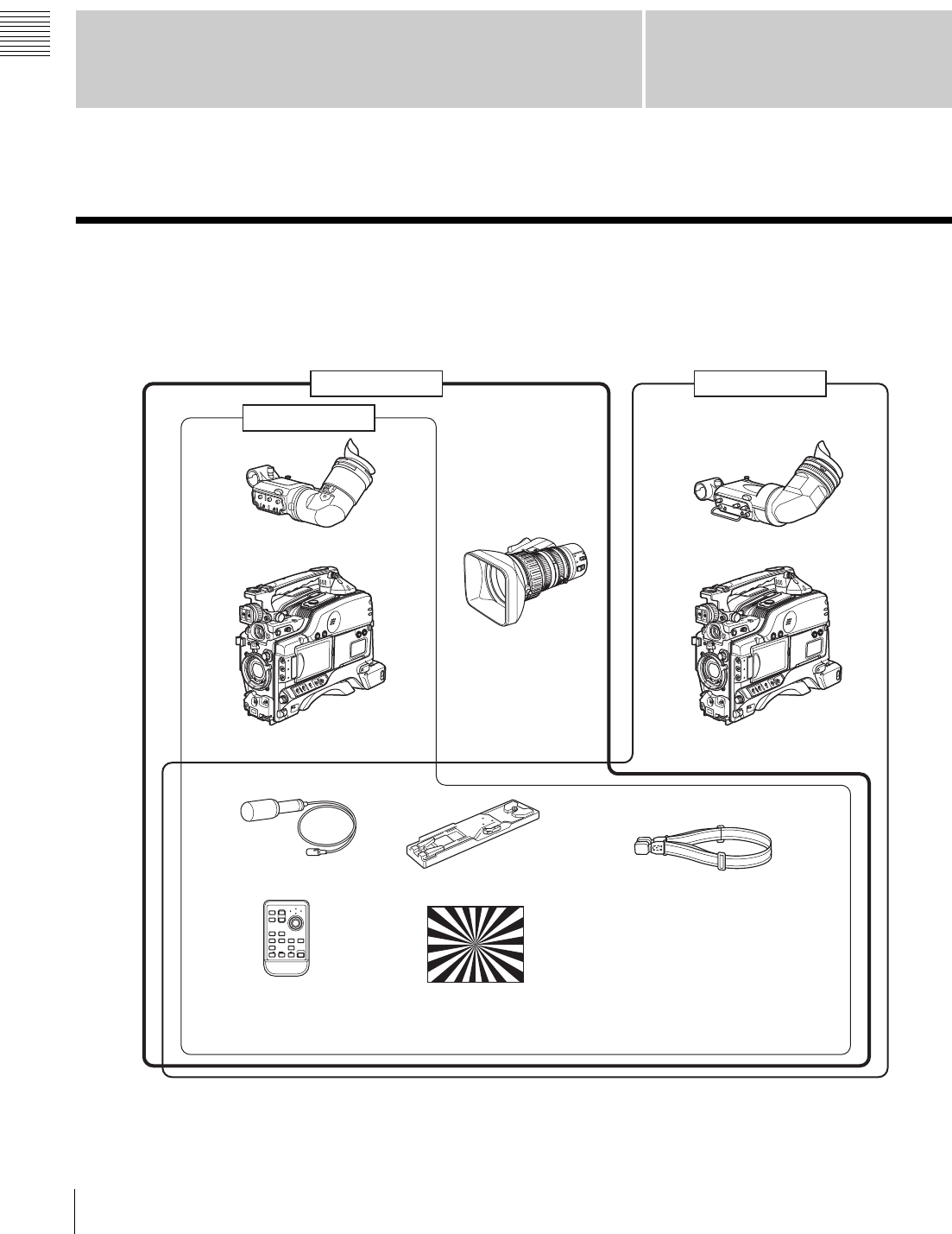
Product Configurations
The PDW-F330/F350 Professional Disc Camcorder series
includes the models PDW-F330L, PDW-F330K, and
PDW-F350L, with different product configurations. The
components and accessories supplied of these models are
as shown in the following figure.
a) Use a tripod adaptor with a suffix of “-E” or later on the model name.
For more details, see “Mounting on a Tripod” (page 45).
1
2
ZOOM
PUSH SET
SHOTMARK
THUMBNAIL
PLAY/PAUSE
STOP
W
.
m
z
>
M
X
xu
PDW-F350L
PDW-F330L
PDW-F330K
T
SUB CLIP
PUSH AFREC PAUSE
REC
FFWDFREV
PREV NEXT
DXF-801/801CE Viewfinder
PDW-F330 Camcorder
Shoulder strap
PDW-F350 Camcorder
Test chart for flange focal
length adjustment
Stereo Microphone VCT-U14 Tripod Adaptor a)
DXF-20W Viewfinder
VCL-719BXS
Auto Focus Lens
RM-F300 Infrared
Remote Commander
•Lens mount cap
•PFD23 Professional Disc
•PDZ-1 Proxy Browsing Software
•Operating Instructions
(Japanese version, English
version, and CD-ROM manual)
•Warranty Booklet

9
Features
Chapter 1 Overview
Features
The PDW-F330/F350 is an XDCAM 1) HD 2) camcorder
integrating an HD video camera using three HD CCDs of
the 1/2-inch type with a total effective pixel count of 1.56
million, and a Professional Disc 1) drive.
This unit provides a range of useful shooting functions for
video production, and allows shooting and recording in
both progressive scan and interlace scan modes with an
HD image having 1080 effective scan lines. Since it also
supports SD 3) DVCAM recording, it can be used through
a transition from SD to HD production.
The use of Professional Disc adds high reliability to
recording and playback, and the unit also includes many
playback and editing functions exploiting the possibilities
of random access.
1) XDCAM and “Professional Disc” are trademarks of Sony Corporation.
2) HD: High Definition
3) SD: Standard Definition
Principal Differences Between the
PDW-F330 and PDW-F350
The specifications of the PDW-F330 and PDW-F350
differ in part, as follows.
a) A DXF-20W 2-inch CRT viewfinder (option) with aspect ratio 16:9 can
be installed in the camcorder.
Camera Features
1/2-inch HD CCD
The use of three interline transfer CCD with an effective
pixel count of approximately 1.56 million (1440 ×1080)
enables high sensitivity, high picture quality, and high
fineness video shooting.
Camera signal processing for high quality
video
A specially-developed ASIC (application specific
integrated circuit) for signal processing provides the
following functions.
• A 12-bit A/D converter ensures recording of pictures
stable at high quality.
• Both progressive and interlace scan modes are
supported.
• You can select from five HD shooting/recording modes:
23.98P 1), 25P, 29.97P 2), 50i, and 59.94i 3), for ideal
support of various applications including digital cinema
production, program production, and event video
production.
• For recording and playback in the DVCAM format (SD),
the aspect ratio (16:9/4:3) and standard broadcasting
system (NTSC/PAL) can be freely selected. Further,
when NTSC is selected, video shot at 23.98P can also be
subjected to 2-3 pulldown and recorded. (The recording
format is then 59.94i.)
1) In this system, shown as 23.9P or 23.98P.
2) In this system, shown as 30P.
3) In this system, shown as 60I.
Shooting functions provide various effects
This unit is equipped with many of the functions provided
in a film camera, allowing the operator creative control
through a variety of techniques.
Slow shutter function
A maximum of 64 frames can be accumulated using the
slow shutter function. In low light levels this allows clear
and noiseless video to be shot, and provides a fantasy
video effect with ghost images.
Time lapse function (interval recording) 1)
Using this function slow-moving subjects can be shot with
the movement compressed in time. This is convenient for
many applications, such as monitoring plant growth, or the
progress of a construction site.
1) This function is available when the recording mode is MPEG HD.
Slow & quick-motion functions 1)
The PDW-F350 has slow & quick-motion functions.
These allow the shooting frame rate to be different from
the playback frame rate, allowing the same functions as
overcranking or undercranking with a film camera. Unlike
low-speed or high-speed playback of normally shot video,
this provides a smooth slow-motion effect, or action
speeded up beyond what is actually possible.
1) This function is available when the recording mode is MPEG HD.
Item PDW-F330 PDW-F350
Viewfinder 1.5-inch CRT,
4:3 aspect ratio
(supplied as
standard) a)
2-inch CRT, aspect
ratio 16:9
(supplied as
standard)
Video output
connectors BNC ×3 (analog
component
outputs, HD/SD
switchable)
BNC (HDSDI
output)
Audio output
connectors RCA ×2 XLR, 5-pin
(balanced output)
Timecode input/
output connectors BNC (input/output
switchable) BNC ×2
(one for input, the
other for output)
Slow & quick-
motion functions No Yes
F350

10 Features
Chapter 1 Overview
Shooting functions to cope with different
shooting conditions
• The ATW 1) and auto iris functions allow shooting with
automated adjustment of the white balance and intenstity
levels to cope with varying ambient lighting conditions.
• By switching among the four levels (including CLEAR)
of neutral density (ND) filter, it is possible to
compensate for lighting conditions, and control the
depth of field.
• When shooting in daylight or other high color
temperature illumination, pressing the 5600K button
instantly switches the color temperature setting to
5600K 2).
• With the GAIN switch, you can adjust the gain of the
video amplifier according to the lighting conditions
when shooting. You can vary the setting in the GAIN
switch positions (H/M/L) to any values in the range –3
dB to +48 dB.
1) Auto Tracing White balance
2) Only when the WHITE BAL switch is in the PRST position
Saving and recalling settings on a
“Memory Stick”
Using a “Memory Stick” 1) (supplied separately), you can
save menu settings adjusted to particular shooting
conditions, and then recall those settings as required.
1) “Memory Stick” is a trademark of Sony Corporation.
Features of the Optical Disc Drive
(VDR)
Support for HD/SD recording and playback
formats
For HD video recording format, MPEG-2 MP@HL
compression is used, and the image quality (bit rate) and
recording time 1) can be selected according to the shooting
application. Recording in the DVCAM format is also
supported. The audio is recorded as four channels or two
channels 2), uncompressed.
1) The recording mode can be selected from the three modes: HQ (High
Quality), SP (Standard Play) and LP (Long Play).
2) DVCAM recording is available for four channels only.
Proxy AV data recording
The Proxy AV data is low resolution data using MPEG-4
(video 1.5 Mbps, audio 64 kbps per channel). With this
unit, when recording HD or SD high resolution data, low
resolution Proxy AV data is automatically generated at the
same time, and recorded.
Since the Proxy AV data is compact, it can be transferred
to a computer or network at high speed, enormously
reducing the storage capacity required for recording.
Exploiting this allows a laptop computer to be used for
editing 1), allows content management on an inexpensive
and compact server, and makes many other applications
easy to implement.
1) Using the supplied PDZ-1 Proxy Browsing Software, a simple EDL (edit
decision list) can be created.
Saving general-purpose files
The Professional Disc has an area of approximately 500
MB provided for storing general-purpose computer files.
Recording and playback in clip units
A clip is created each time recording is started and
stopped.
• Recording always writes to an empty area of the disc.
Therefore, even if playback is carried out between
shooting sessions, there is no danger of the next shooting
inadvertently overwriting previous material. During
playback, the next they are recorded can always be
started immediately.
• Since unwanted clips can be deleted on this unit
immediately after they are recorded, the disc capacity
can be used effectively.
Convenient playback and search functions
exploiting the disc characteristics
Thumbnail search
Pressing the THUMBNAIL button on this unit displays a
representative image for each clip as a thumbnail on the
LCD (liquid crystal display) monitor, in the viewfinder,
and on the external video monitor.
Selecting a thumbnail with the cursor and pressing the
PLAY/PAUSE button allows any clip to be checked
easily.
Essence mark search
During or after movie recording, an essence mark can be
recorded on any scene. A list of frames with an essence
mark recorded can be displayed on the LCD monitor, in
the viewfinder, and on the external video monitor. Essence
marks can also be added after recording using the supplied
PDZ-1 Proxy Browsing Software.
Expand function
The length of any clip selected in the thumbnail list can be
divided into 12, and the first frames of these 12 divisions
can also displayed in the form of a thumbnail list. With this
function, it is easy to search rapidly for scenes within a
particular clip. This function is called the expand function,
and it can be applied to the same clip up to three times to
display 1728 thumbnails in a list.

11
Features
Chapter 1 Overview
Scene selection
You can select clips on the disc to create a clip list. The
clips in this list can be played back in any order. A single
disc can hold up to 99 clip lists.
Audio recording functions
Audio is recorded as uncompressed data with 16-bit
quantization, and a sampling frequency of 48 kHz.
Depending on shooting requirements and recording time,
either two or four audio channels can be selected. (Only
four channels for DVCAM recording.)
• The unit is equipped with a stereo front microphone.
• There are two AUDIO IN connectors (XLR, 3-pin) on
the rear of the unit, which can be used for line and
microphone input.
• The CA-WR855 Camera Adaptor (supplied separately)
can be used to install the WRR-855 series slot-in type
UHF synthesized tuner (supplied separately) without
using any connecting cable.
• The audio signals to be recorded on the disc can be freely
selected from the audio inputs to the stereo microphone,
AUDIO IN connectors and the UHF synthesized tuner,
and assigned to any desired audio channel.
Input/Output Features
Equipped with an i.LINK connector
The i.LINK connector on this unit supports the following
two functions.
DV stream output (AV/C 1) mode connection): A DV
stream can be output from the i.LINK connector on
this unit, and recorded on a DV recorder or nonlinear
editor supporting DV. For recording and playback in
MPEG HD format, a down-converted DV stream can
be output.
File access from a computer (FAM 2) connection): An
FAM connection between this unit and a computer
allows the video, audio, and metadata information on
the disc to be read and written as files. (The data can
be written and read as normal files on a computer.)
With this function, a nonlinear editing device
connected to this unit can be used for direct HD video
editing or simple Proxy A/V data editing, enabling a
more efficient workflow.
1) Audio/Video Control
2) File Access Mode
Other signal input/output connectors
HDSDI output connector
The audio signals are embedded in the video signal. The
HD video and audio output from this connector can be
recorded on an external HD device.
HD/SD analog component output connector
During HD video recording and playback, either an HD
signal or down-converted SD signal can be output. (The
output signal selection is carried out in a menu.)
Composite video output connector
The 50i/25P video is output as the PAL signal, the 60i/30P
video is output as the NTSC signal, and the 23.98P video
is output as the NTSC signal which has undergone 2-3
pull-down processing.
Timecode input/output connectors
Provided with a single input/output connector (controlled
by a switch).
Provided with one input connector and one output
connector.
GENLOCK connector
The SD or HD reference signal can be input to apply a
genlock to the camera.
Video light connector
There is an interface connector for a maximum 50 W video
light, and a control switch. Depending on the switch
setting, the light can be turned on and off as recording
starts and stops.
Remote control connector
Connect the RM-B150/B750 remote control unit (supplied
separately) or other remote commander, to allow remote
operation of the shooting functions of this unit.
Audio output connectors
Provided with RCA phono jacks, allowing stereo output.
Provided with XLR connectors (5-pin, balanced output),
allowing stereo output.
Earphone jack (monaural/stereo)
Audio channels to be monitored can be selected with the
MONITOR switch on the side of the unit. Switch between
monaural and stereo using the menus.
F350
F330
F330
F350
F330
F350

12 Features
Chapter 1 Overview
Other Features
User-friendly interface functions
ASSIGN (assignable) switches
The unit is provided with four ASSIGN switches; two on
the front and the others on the top of the grip. You can
assign various functions to these switches. By assigning
frequently used functions to the switches, you can call up
the desired functions instantly, for example during
shooting operations. The functions that can be assigned are
as follows.
• Lens zoom control (telephoto/wide-angle)
• Easy focus function
• Turbo gain function
• Enabling and disabling the infrared remote commander
function
Infrared remote commander
You can use the supplied infrared remote commander to
carry out the following operations.
• Starting and stopping recording, auto focusing, zoom
control (telephoto/wide-angle)
• Recording essence marks (shot mark 1 and shot mark 2)
• Playback, high-speed playback / reverse high-speed
playback, jump to the next/previous clip
• Thumbnail display and selection, a clip list selection
To prevent misoperation, the remote commander function
is disabled when this unit is powered on. To use the
infrared remote commander, you must enable the remote
commander function using a menu. If you use the remote
commander frequently, it is recommended that you assign
the function of this menu to one of the ASSIGN switch.
3.5-inch color LCD monitor
The LCD monitor on the side of the unit can be switched
to show the following images and data.
• Status information, including audio level meters for four
channels and timecode
• List of thumbnails of the video recorded on the
Professional Disc
• A playback image of the video recorded on the
Professional Disc
• The camera image
• The image in the LCD monitor has about 4% cropped
from each of the four edges of the actually captured
video image. For accurate framing, always use the
viewfinder.
• When the area of use is set to “PAL AREA” (frame
frequency 50i or 25P), the image in the LCD monitor
may be reduced in quality, with jaggies on diagonal
lines, but this is not a malfunction.
Note
Notes
13
Location and Function of Parts
Chapter 1 Overview
Location and Function of Parts
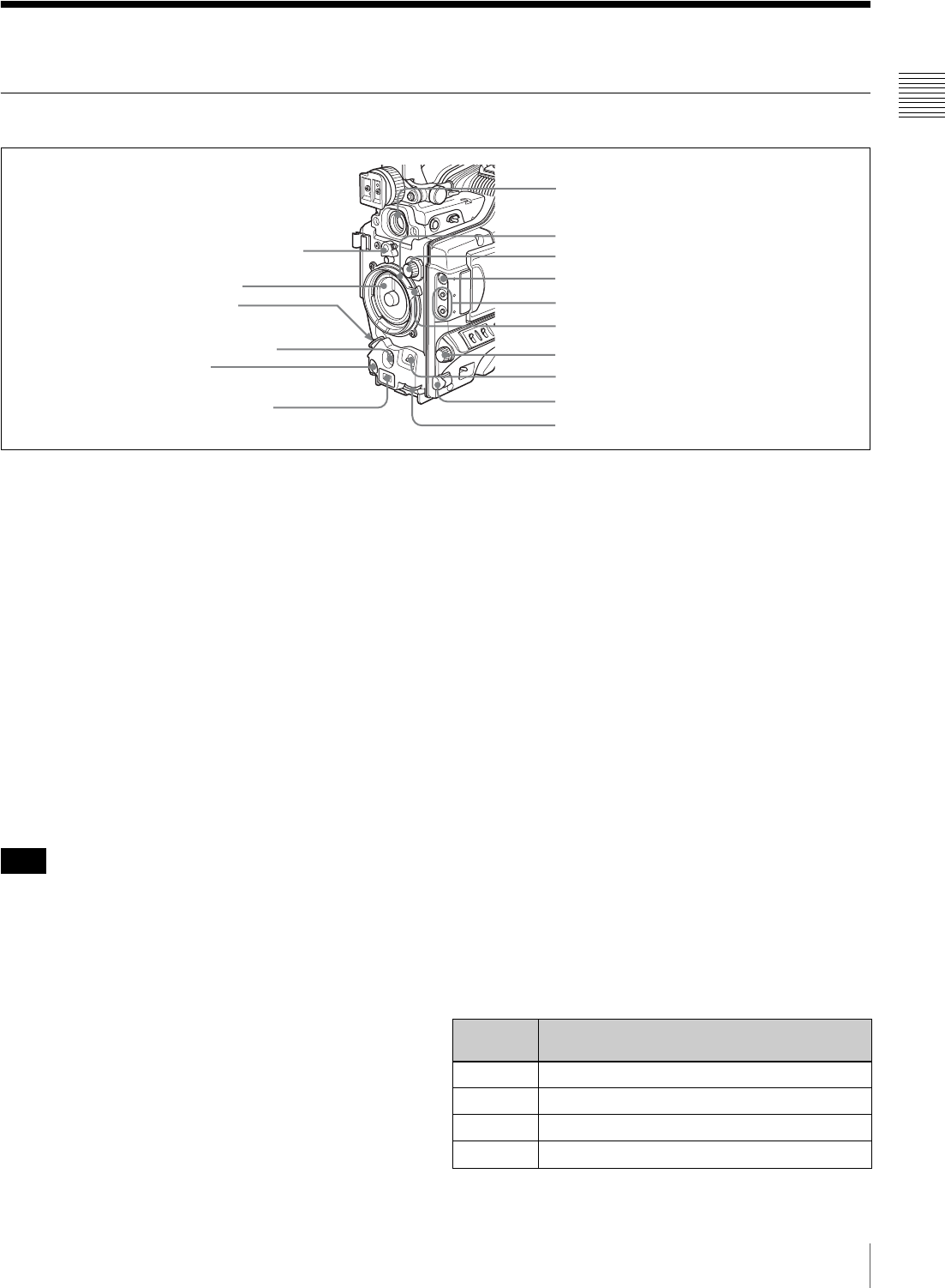
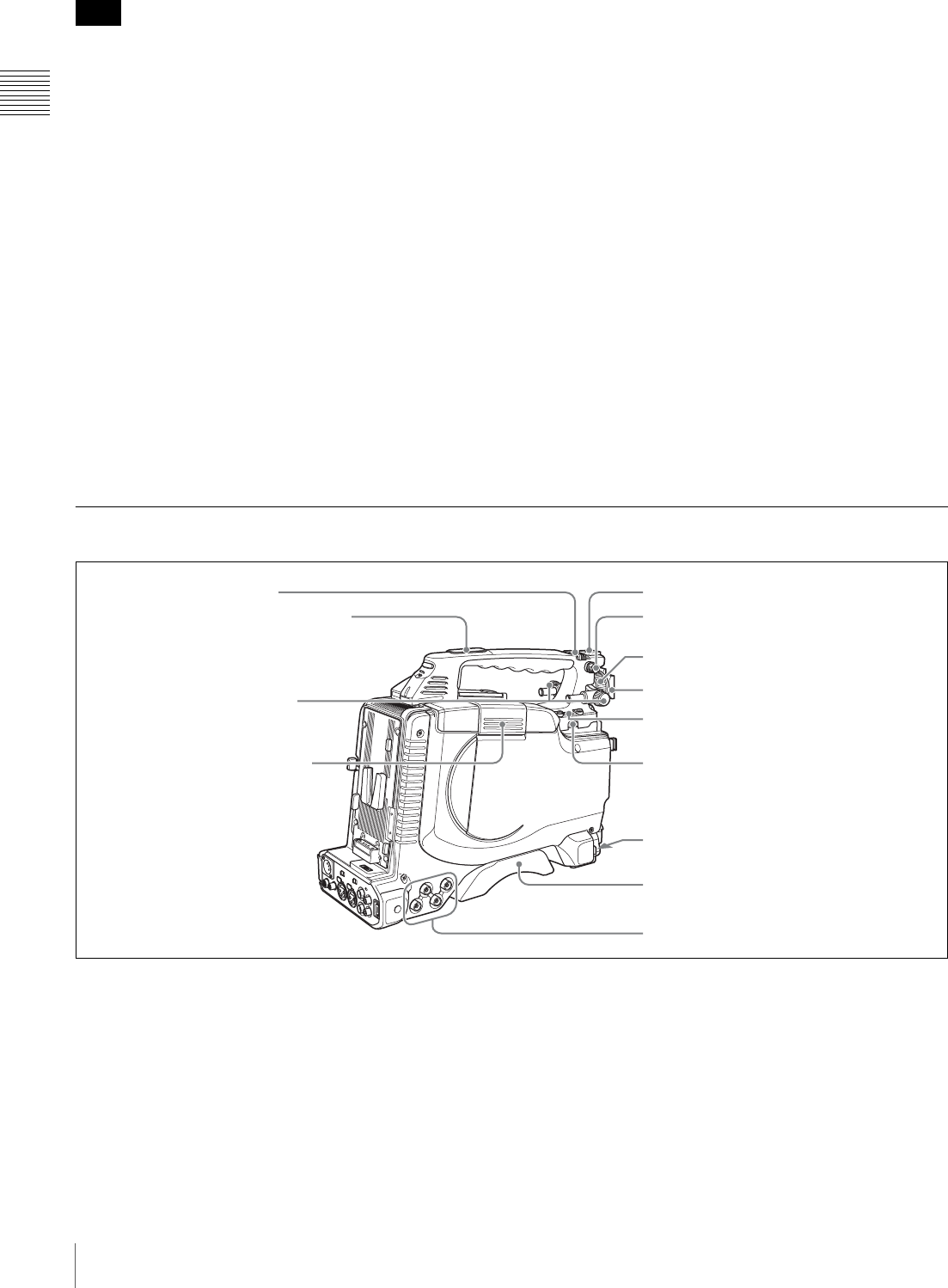
Front
aLens mount securing rubber
After locking the lens in position using the lens locking
lever, fit this rubber over the lower of the two projections.
This fixes the lens mount, preventing it from coming loose.
bLens mount cap
Remove by pushing up the lens locking lever (see page
14). When no lens is mounted, keep this cap fitted for
protection from dust.
c LENS connector (12-pin)
Connect the lens cable mainly for using a 2/3-inch type
lens. (This connector is not used for a 1/2-inch type lens,
which is connected by the hot shoe inside the lens mount.)
Consult your Sony dealer when you are using a lens other
than VCL-719BXS (supplied with the PDW-F330K).
When mounting or removing the lens on this unit, power
off this unit first.
dAUTO W/B BAL (automatic white/black balance
adjustment) switch
Activates the automatic white/black balance adjustment
functions.
WHT: Adjusts the white balance automatically. If the
WHITE BAL switch (see page 16) is set to A or B, the
white balance setting is stored in the corresponding
memory. If the WHITE BAL switch is set to PRST,
the automatic white balance adjustment function does
not operate.
BLK: Adjusts the black set and black balance
automatically.
eREC (recording start) button
Press to start recording. Press it again to stop recording.
The effect is the same as that of the REC button on the
supplied lens. When the REC SWITCH function is
assigned to an ASSIGN switch on the ASSIGNABLE page
of the OPERATION menu, you can use the switch as the
REC button.
fAuto focus ranging sensor
When an VCL-719BXS (supplied with the PDW-F330K)
auto focus lens is mounted, this measures the distance to
the subject, and automatically focuses the lens.
This sensor is provided as an auxiliary function for
improving the automatic focusing speed. Even if this
sensor is blocked, the focusing precision will not be
affected.
gVF (viewfinder) connector (20-pin)
Connect the supplied viewfinder.
hLens mount (special bayonet mount)
Attach the lens.
iFILTER selector
Selects from the four neutral density (ND) filters built into
this unit.
5REC button
2Lens mount cap
4AUTO W/B BAL switch
8Lens mount
9FILTER selector
3LENS connector
7VF connector
0ZEBRA button
qa ASSIGN 1/2 switches
qs Lens locking lever
qd MENU knob
qf SHUTTER switch
qh AUDIO LEVEL knob
1Lens mount securing rubber
6Auto focus ranging
sensor
qg Remote commander receptor
Note
Position
number
ND filter
1 CLEAR
21/4 ND (attenuates light to approximately 1/4)
31/16 ND (attenuates light to approximately 1/16)
41/64 ND (attenuates light to approximately 1/64)

14 Location and Function of Parts
Chapter 1 Overview
Normally set this to 1 (CLEAR).
For shooting with the lens iris wide open for reduced depth
of field, or when the subject is too brightly lit and the auto
iris function does not operate correctly, select an
appropriate position.
When this selector is used with the menu item for filter
selection display set to ON (see page 137), the new setting
appears on the viewfinder screen for about 3 seconds.
You can change a MAINTENANCE menu setting so that
different white balance settings can be stored for different
FILTER selector positions. This allows you to
automatically obtain optimum white balance for the
current shooting conditions in linkage with the filter
selection.
For details, see “To adjust the white balance” (page 60).
jZEBRA button
Press to display a zebra pattern (diagonal stripes) in the
viewfinder screen.
The zebra pattern is factory set to indicate picture areas
where the video level is approximately 70%. However, on
the VF SETTING page of the OPERATION menu, you
can change the setting so that areas where the video level
is 100% and above are also indicated at the same time. In
addition, you can also change the video level for
displaying the zebra pattern in the range from 30% to
107%.
For details, see “Setting the Viewfinder Screen Display”
on page 138.
kASSIGN 1/2 switches
You can assign the desired functions to each of the
ASSIGN 1 and ASSIGN 2 switches on the ASSIGNABLE
page of the OPERATION menu.
The following functions are factory preset to the switches.
For details, see “Assigning Functions to ASSIGN
Switches” on page 142.
lLens locking lever
After inserting the lens in the lens mount, rotate the lens
mount ring with this lever to lock the lens in position.
After locking the lens, be sure to use the lens mount
securing rubber to prevent the lens from becoming
detached.
mMENU knob
Changes the page selection or a setting within the menu.
For details about how to use the MENU knob, see “Basic
Menu Operations” on page 131.
nSHUTTER switch
Set to ON to use the electronic shutter. Flick to SEL to
switch the shutter speed or shutter mode setting within the
range previously set with the menu. When this switch is
operated, the new setting appears on the setting change/
adjustment progress message display area for about 3
seconds.
For details about the shutter speed and shutter mode
settings, see “Setting the Electronic Shutter” on page 62.
oRemote commander receptor
Press the ASSIGN switch which is assigned to enable/
disable the remote commander function, and then aim the
supplied infrared remote commander at this receptor.
To prevent misoperation, the remote commander function
is disabled when the camcorder is powered on. To use the
infrared remote commander, it is necessary to assign the
remote commander enabling/disabling function to an
ASSIGN switch, and then press the ASSIGN switch to
enable the remote commander. (This function is factory
preset to the ASSIGN 2 switch.)
For details of how to assign a particular function to an
ASSIGN switch, see page 142.
pAUDIO LEVEL knob
Adjusts the input level of audio channels 1and 2.
You can disable this knob by setting the AUDIO CH1
LEVEL and AUDIO CH2 LEVEL items on the AUDIO-1
page of the MAINTENANCE menu. (The knob is factory
preset so that it is enabled.)
Switch Function
ASSIGN 1 EZ MODE (EZ mode ON/OFF)
ASSIGN 2 IR REMOTE (infrared remote commander
enabled/disabled)
Note
15
Location and Function of Parts
Chapter 1 Overview
Right Side
Near the front
a5600K button
Press to light the button and switch the standard color
temperature for shooting to 5600K. Use this button for
outdoor shooting in daytime or shooting under lighting
with higher temperature. This button is effective only
when the WHITE BAL switch is set to PRST.
bLIGHT switch
Determines how a video light connected to the LIGHT
connector (see page 23) is turned on and off.
AUTO: When the POWER switch of the video light is in
the on position, the video light is turned on
automatically while the camcorder is recording.
MAN: You can turn the video light on or off manually,
using its own switch.
• When this switch is set to AUTO, at the beginning of the
recording, the picture is recorded even though the
lighting may fluctuate until the video light comes on. If
the beginning of the recording is important, you should
set this switch to MAN. However, when using the
interval recording mode, the video light is automatically
turned on immediately before recording starts.
• To ensure proper operation of the video light, Sony
recommends the use of the BP-GL95 Battery Pack with
the camcorder.
cGAIN switch
Switches the gain of the video amplifier to match the
lighting conditions during shooting. The gains
corresponding to the L, M, and H settings can be selected
in the menu. (The factory settings are L = 0 dB, M = 9 dB,
and H = 18 dB.)
When this switch is adjusted, the new setting appears on
the setting change/adjustment progress message display
area of the viewfinder screen for about 3 seconds.
For details, see “Setting Gain Values for the GAIN Switch
Positions” on page 140.
dVDR SAVE/STBY (VDR save/standby) switch
Switches the status of the power supply to the VDR while
recording is paused (REC PAUSE).
SAVE: At the start of recording, an internal operating
sound may be recorded. There is a small delay from
pressing the REC button until recording starts, since
the power consumption is less than in the standby
state.
STBY: When the REC button is pressed, recording starts
immediately.
• Even if the switch is on the SAVE side, the unit exits
SAVE (power saving) mode and enters STBY (standby)
mode whenever you exit REC PAUSE mode by carrying
out playback to check the recorded video or by
displaying the thumbnail screen (page 82). To put the
unit into SAVE mode again, put the unit into REC
PAUSE mode again after recording, or power the unit
off and on again.
• An internal operating sound may be recorded at the start
of recording when the VDR SAVE/STBY switch is set
to SAVE.
ePOWER switch
Turns the main power supply on and off.
fMONITOR (monitor volume adjustment) knob
Controls the volume of the sound other than the warning
tone that is output via the built-in speaker or optional
earphones. When the knob is turned to the minimum
setting, no sound can be heard.
qa OUTPUT/DCC switch
15600K button
3GAIN switch
6MONITOR knob
7ALARM knob
2LIGHT switch
5POWER switch
8LCD monitor
9MENU switch
0WHITE BAL switch
4VDR SAVE/STBY switch
Notes
Notes
16 Location and Function of Parts
Chapter 1 Overview
gALARM (alarm tone volume adjustment) knob
Controls the volume of the warning tone that is output via
the built-in speaker or optional earphones. When the knob
is turned to the minimum position, no sound can be heard.
hLCD monitor
Displays camera video, VDR-related warnings, remaining
battery capacity, remaining disc space, audio levels, time
data, and so on.
For details, see “Status Display on the LCD Monitor” on
page 17.
iMENU switch
When flicking toward ON, the menu is displayed. When
flicking toward STATUS, the status of the camcorder (of
current settings) is displayed.
For details, see “Displaying Menus” on page 131.
jWHITE BAL (white balance memory) switch
Controls adjustment of the white balance.
PRST: Adjusts the color temperature to the preset value
(the factory default setting: 3200K). Use this setting
when you have no time to adjust the white balance.
A or B: Recall the white balance adjustment settings
already stored in A or B.
Press the AUTO W/B BAL switch (see page 13) on
the WHT side, to automatically adjust the white
balance, and save the adjustment settings in memory
A or memory B. The 5600K button does not function.
You can use the AUTO W/B BAL switch even when
ATW 1) is in use.
B (ATW): When this switch is set to B and WHITE
SWITCH <B> is set to ATW on the WHITE
SETTING page of the MAINTENANCE menu, ATW
is activated. When this switch is adjusted, the new
setting appears on the setting change/adjustment
progress message display area of the viewfinder
screen for about 3 seconds. You can assign the ATW
function to an ASSIGN switch on the ASSIGNABLE
page of the OPERATION menu.
For details about how to assign the function to an ASSIGN
switch, see “Assigning Functions to ASSIGN Switches” on
page 142.
1) ATW (Auto Tracing White Balance): The white balance of the picture
being shot is adjusted automatically for varying lighting conditions.
kOUTPUT/DCC (output signal/dynamic contrast
control) switch
Switches the video signal, which is output to the video disc
drive (referred to as “VDR”), viewfinder, and video
monitor from the camera section, between the following
two.
BARS: Outputs the color bar signal.
CAM: Outputs the video signal from the camera. When
this is selected, you can switch DCC 1) on and off.
1) DCC (Dynamic Contrast Control): Against a very bright background
with the iris opening adjusted to the subject, objects in the background will
be lost in the glare. The DCC function will suppress the high intensity and
restore much of the lost detail and is particularly effective in the following
cases.
• Shooting people in the shade on a sunny day
• Shooting a subject indoors, against a background through a window
• Any high contrast scene
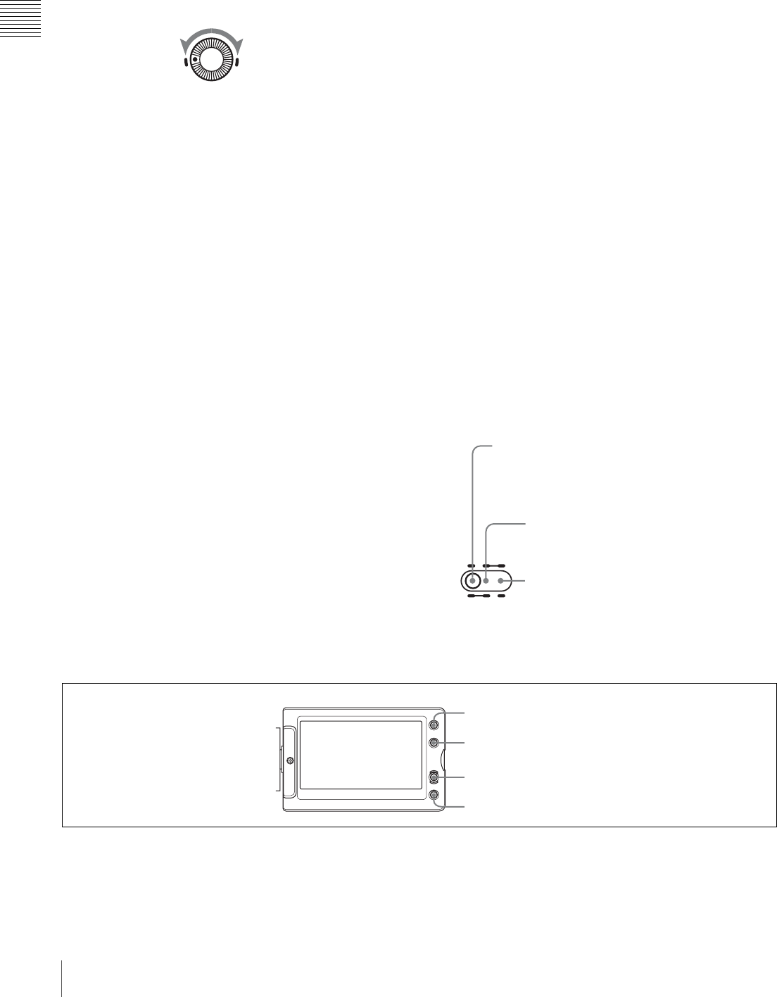
LCD monitor operating buttons
aDISPLAY/EXPAND button
Each time pressing this button, the display in the LCD
monitor changes as follows.
ALARM
Minimum Maximum
OUTPUT
DCC
CAMBARS
ONOFF
OUTPUT: BARS, DCC: OFF
A color bar signal is output and the DCC circuit does not
operate. Use this setting to adjust the video monitor, to
record the color bar signal, etc.
OUTPUT: CAM, DCC: OFF
The video signal from the camera is output, and
the DCC circuit does not operate.
OUTPUT: CAM, DCC: ON
The video signal from the camera is output, and
the DCC circuit operates.
1DISPLAY/EXPAND button
2COUNTER/CHAPTER button
3RESET button
4BRIGHT button
17
Location and Function of Parts
Chapter 1 Overview
If you press this button when the thumbnail screen is
displayed, the duration of the selected clip is divided into
12, and the first frame of each of the divisions is shown in
a further thumbnail display (expand function). Each time
you press the button, the division is repeated (to a
maximum of three times, with 1728 divisions). Hold down
the SHIFT button and press this button to step back
through the division process.
For details of the expand function, see page 85.
bCOUNTER/CHAPTER (counter display toggle/
chapter) button
Each time this button is pressed, the counter display
section changes as follows. This setting is activated only
when the LCD monitor display is set to STATUS with the
DISPLAY/EXPAND button.
COUNTER: Displays the elapsed recording/playback
time.
TC: Displays timecode.
U-BIT: Displays user bits data.
If you press this button when the thumbnail screen is
displayed, those frames on which essence marks are
recorded appear in a list (chapter function). Press the
button once more to return to the normal thumbnail
display.
By displaying thumbnails with essence marks attached in
place of index frames, you can check the contents of clips
more easily and more quickly. This is also useful for
cueing up long clips.
For details of the chapter function, see page 85.
cRESET button
Resets the display of the time data when the LCD monitor
display is set to STATUS or CHAR with the DISPLAY/
EXPAND button. According to the settings of the
PRESET/REGEN/CLOCK switch (see page 22) and the
F-RUN/SET/R-RUN switch (see page 22), this button
resets the display as follows.
a) Of the timecode bits for every frame recorded on the disc, those bits which
can be used to record useful information for the user such as scene number,
shooting place, etc.
b) Can only be reset when the display is set to STATUS. When it is set to
CHAR, resetting is not possible.
For details, see “Setting the Time Data” on page 66.
If you press this button when thumbnails of frames with
essence marks are displayed using the COUNTER/
CHAPTER button, or when thumbnails of clip divisions
are displayed using the DISPLAY/EXPAND button, then
the display returns to the normal thumbnail display.
dBRIGHT (brightness) button
Sets the backlight brightness. Each time you press this
button, the backlight brightness cycles through the
following four levels:
H: Select this to view the LCD monitor in outdoor
daylight.
M: Brightness level between H and L.
L: Select this to view the LCD monitor indoors or outside
at night.
OFF: Turn the backlight off (you can view video under
normal lighting). Select this in outdoor daylight when
the LCD monitor screen is subjected to direct
sunlight.
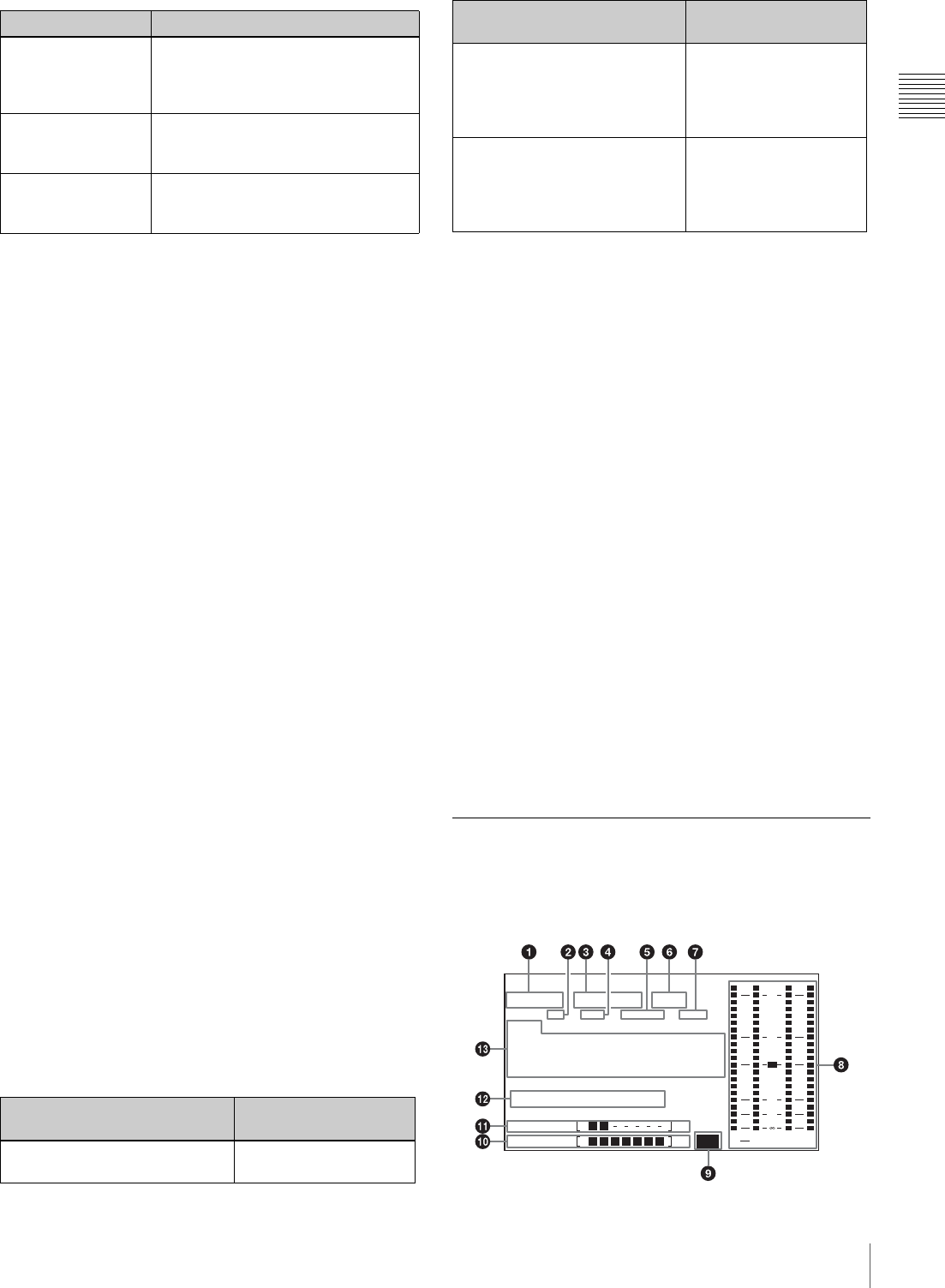
Status Display on the LCD Monitor
The following display appears when the LCD monitor
display is set to STATUS with the DISPLAY/EXPAND
button.
Display indication Meaning
Video with
superimposed
information
When the MENU switch is flicked
toward STATUS, the principal settings
of this unit appear as on the
viewfinder screen.
Video without
superimposed
information
The video only appears.
Status display Counter indications, warnings, audio
levels, and similar information
appears. No video image appears.
Settings of buttons and
switches
To reset
COUNTER/CHAPTER button:
COUNTER Counter to 0:00:00:00
COUNTER/CHAPTER button:
TC
PRESET/REGEN/CLOCK
switch: PRESET
F-RUN/SET/R-RUN switch: SET
Timecode to 00:00:00:00
COUNTER/CHAPTER button:
U-BIT
PRESET/REGEN/CLOCK
switch: PRESET
F-RUN/SET/R-RUN switch: SET
User bits data a) to 00 00
00 00 b)
Settings of buttons and
switches
To reset
W A R N I N G : H U M I D
H D S P
T C G
01 : 23 : 45 15:
2 3 . 9 8 P 4 c h
H
P B N D F E X T - L K
21
H O L D
M I N S E C F R M
D I S C E B
B A T T E F Li
ST
43
d B
O V E R
P E U K
2
0
18 Location and Function of Parts
Chapter 1 Overview
aVideo format
Indicates the format of video being currently played back
or recorded.
HD HQ: HQ (high quality) mode in the MPEG HD video
format
HD SP: SP (standard play) mode in the MPEG HD video
format
HD LP: LP (long play) mode in the MPEG HD video
format
DVCAM: DVCAM format
bPlayback indicator
Appears during playback.
cCamera scan mode indicator
Indicates the camera scan mode of video being currently
played back or recorded.
• If NTSC AREA is selected 1)
60I: 59.94 fields per second, interlace scan mode
30P: 29.97 frames per second, progressive scan mode
23.98P: 23.98 frames per second, progressive scan mode
(converted to 60i at 2-3 pulldown)
• If PAL AREA is selected 1)
50I: 50 fields per second, interlace scan mode
25P: 25 frames per second, progressive scan mode
1) COUNTRY setting on the FORMAT page of the OPERATION menu (see
page 111).
There may be no indication displayed when this unit
cannot identify the camera scan mode, for example, when
playing back a disc recorded with other equipment.
dNon-drop-frame mode indicator
Appears when non-drop-frame timecode is selected.
eExternal synchronization indicator
Appears when the internal timecode generator is locked to
an external signal input to the TC IN connector 1).
1) For the PDW-F350. For the PDW-F330, the TC connector (IN/OUT
switch set to IN).
fAudio channel display
Shows the audio channel mode during recording or
playback.
2ch: two-channel mode (only when the MPEG HD format
is selected)
4ch: four-channel mode
gHold indicator
Appears when the internal timecode generator is stopped.
hAudio level indicators
Indicates the audio recording or playback levels of
channels 1 to 4.
iLithium battery low voltage warning
Appears when the voltage of the internal lithium backup
battery (CR2032) is low. If this indication appears, replace
the lithium battery immediately (see page 36).
jRemaining battery capacity indicator
kRemaining disc capacity indicator
lWarning indicator area
Displays warnings when trouble with recording or
moisture condensation occurs.
For details, see “Operation Warnings” on page 165.
Note
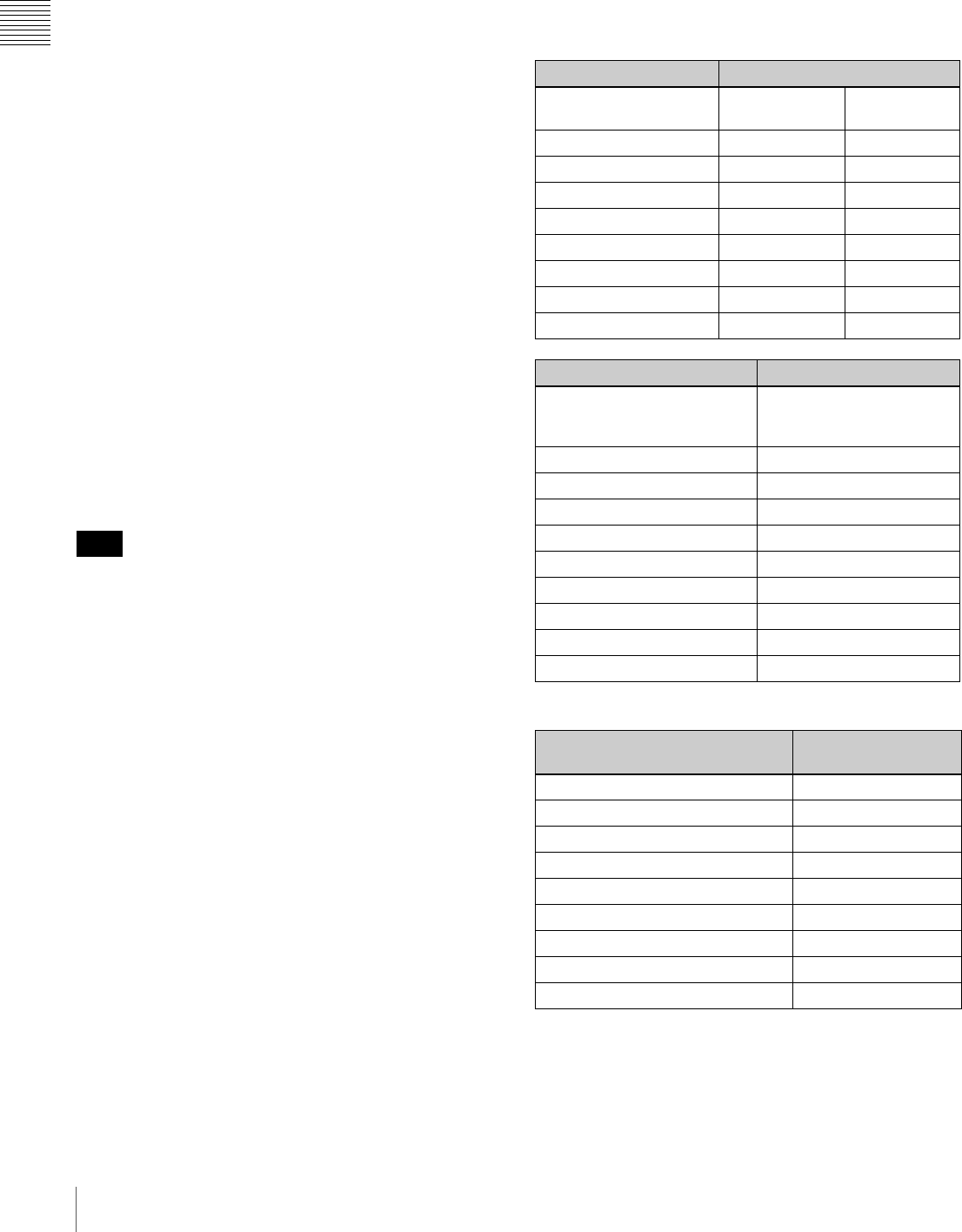
Indication Battery voltage
BP-L90A/L60S/
L80S
Other
batteries
BATT E [ ■■■■■■■ ] F 15.5 V or more 17.0 V or more
BATT E [ ■■■■■■ ] F 15.1 to 15.5 V 16.0 to 17.0 V
BATT E [ ■■■■■ ] F 14.6 to 15.1 V 15.0 to 16.0 V
BATT E [ ■■■■ ] F 13.8 to 14.6 V 14.0 to 15.0 V
BATT E [ ■■■ ] F 12.9 to 13.8 V 13.0 to 14.0 V
BATT E [ ■■ ] F 12.0 to 12.9 V 12.0 to 13.0 V
BATT E [ ■ ] F 10.8 to 12.0 V 11.0 to 12.0 V
BATT E [ ] F 10.8 V or less 11.0 V or less
Indication Battery voltage
BP-GL95/GL65/IL75/
M100, Anton Bauer
Battery System
BATT E [ ■■■■■■■ ] F 80 to 100%
BATT E [ ■■■■■■■ ] 70%
BATT E [ ■■■■■■ ] 60%
BATT E [ ■■■■■ ] 50%
BATT E [ ■■■■ ] 40%
BATT E [ ■■■ ] 30%
BATT E [ ■■ ] 20%
BATT E [ ■ ] 10%
BATT E [ ] 0%
Indication Remaining recording
time
DISC E [ ■■■■■■■ ] B 30 minutes
DISC E [ ■■■■■■ ] B 25 to 30 minutes
DISC E [ ■■■■■ ] B 20 to 25 minutes
DISC E [ ■■■■ ] B 15 to 20 minutes
DISC E [ ■■■ ] B 10 to 15 minutes
DISC E [ ■■ ] B 5 to 10 minutes
DISC E [ ■ ] B 2 to 5 minutes
DISC E [ ■ ] B (flashing) 0 to 2 minutes
DISC E [ ] B (flashing) 0 minutes
19
Location and Function of Parts
Chapter 1 Overview
mTime counter display
Each press of the COUNTER/CHAPTER button cycles
through displays of timecode, user bits, and counter
information. You can display the date or time using the
four-way arrow key on the side control panel.
TCG: Value of timecode generator
TCR: Value of timecode reader
UBG: Value of user bits generator
UBR: Value of user bits reader
CNT: Counter information
CLK: Time by the internal clock
TCG and UBG can be displayed when the disc is stopped
and during recording, and TCR and UBR are displayed
during playback.
CLK appears when the COUNTER/CHAPTER button has
been pressed to display TC, and the PRESET/REGEN/
CLOCK switch is set to CLOCK.
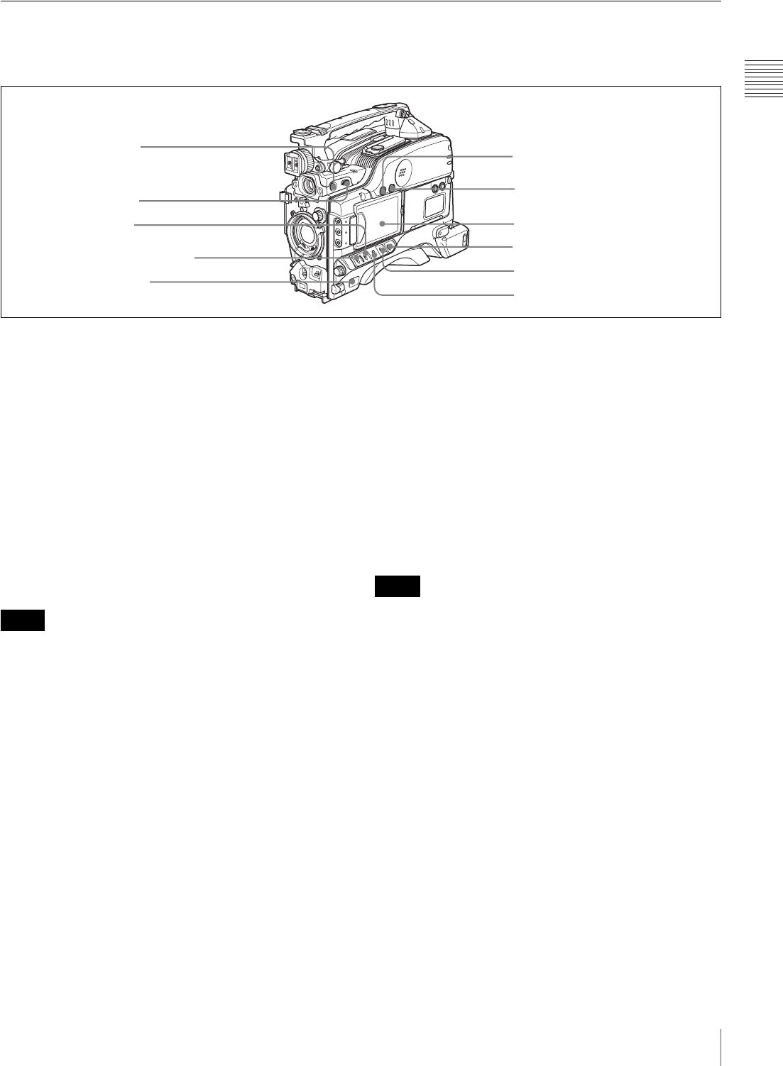
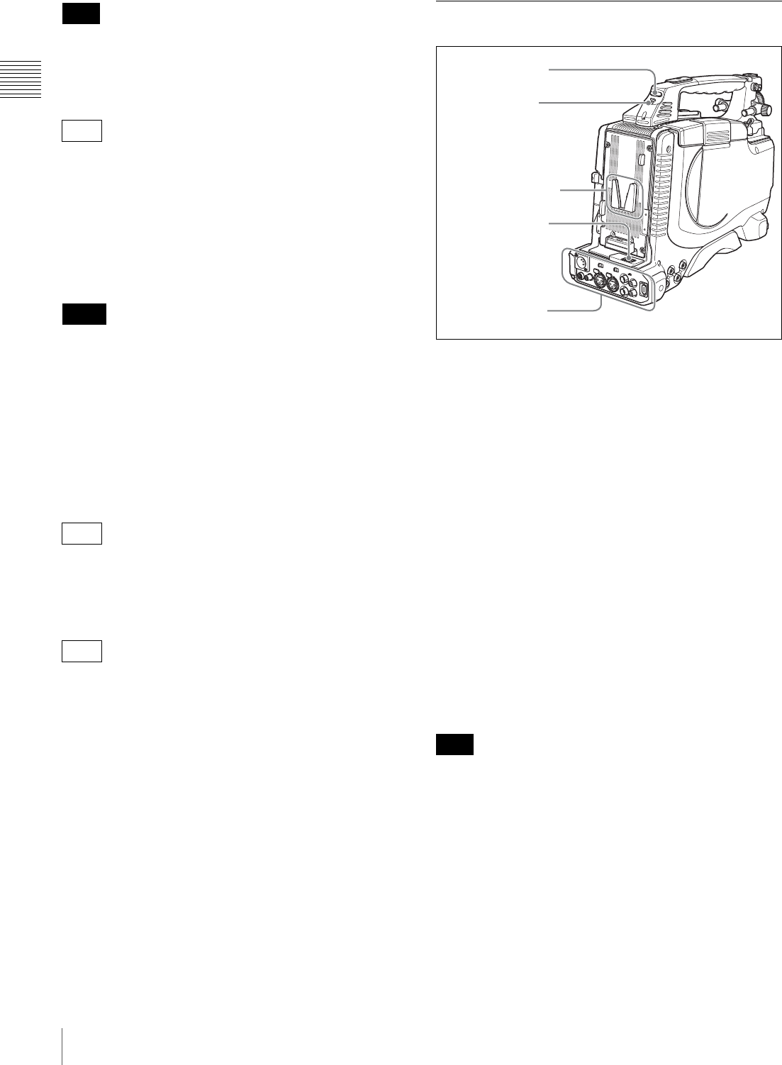
Near the rear
aWARNING indicator
Lights up or flashes when an abnormality occurs in the
VDR section.
For details about the meaning of the states of the
WARNING indicator, see “Operation Warnings” on
page 165.
bACCESS indicator
This lights when data is written to or read from the disc.
cBuilt-in speaker
The speaker can be used to monitor E-E 1) sound during
recording, and playback sound during playback. The
speaker also sounds alarms to reinforce visual warnings.
If you connect earphones to the EARPHONE jack, the
speaker output is suppressed automatically.
1) E-E: Abbreviation of “Electric-to-Electric”. In E-E mode, video and audio
signals input to the camcorder are output after passing through internal
electric circuits only. This can be used to check input signals.
For details about alarms, see “Operation Warnings” on
page 165.
dProtection cover of the side control panel
Open to access the side control panel (see page 20).
eEARPHONE jack
By plugging earphones, you can monitor the E-E sound
during recording and playback sound during playback.
When an alarm is indicated, you can hear the alarm sound
through the earphones. Plugging earphones into the jack
automatically cuts off the sound from the built-in speaker.
You can select monaural or stereo on the AUDIO-2 page
of the MAINTENANCE menu.
F REC
PREC
Z
PLAY/PAUSE
STOP NEXT
F FWD
m
.
NX
x >
M
EJECT
1WARNING indicator
2ACCESS indicator
3Built-in speaker
4Protection cover of the side control panel
5EARPHONE jack
6EJECT button and indicator
7F REV button and indicator
8PLAY/PAUSE button and indicator
9F FWD button and indicator
0NEXT button
qa STOP button
qs PREV button
20 Location and Function of Parts
Chapter 1 Overview
fEJECT button and indicator
Press this button to insert a disc or eject the disc. The
indicator flashes while the disc is being ejected.
gF REV (fast reverse) button and indicator
This plays back at high speed in the reverse direction. The
indicator lights during high-speed playback in the reverse
direction.
hPLAY/PAUSE button and indicator
Press this button to view play back video images using the
viewfinder screen or a color video monitor. The indicator
lights during playback.
Press this button again during playback to pause,
outputting a still image. At this time the indicator flashes.
This unit is equipped with a color search function at
approximately four times normal playback speed, for easy
checking of recorded material. To use the color search
function at approximately four times normal playback
speed, press the F REV button or F FWD button during
playback.
At this time the PLAY indicator and F REV or F FWD
indicator light.
iF FWD (fast forward) button and indicator
This plays back at high speed in the forward direction. The
indicator lights during high-speed playback in the forward
direction.
jNEXT button
This jumps to the start of the next clip, then pauses. During
the jump, the F FWD indicator flashes. If you press this
together with the F FWD button, the jump is to the last
frame of the last recorded clip on the disc.
kSTOP button
Press this to stop disc playback.
lPREV (previous) button
This jumps to the start of the current clip, then pauses.
During the jump, the F REV indicator flashes. If you press
this together with the F REV button, the jump is to the start
of the first recorded clip on the disc.
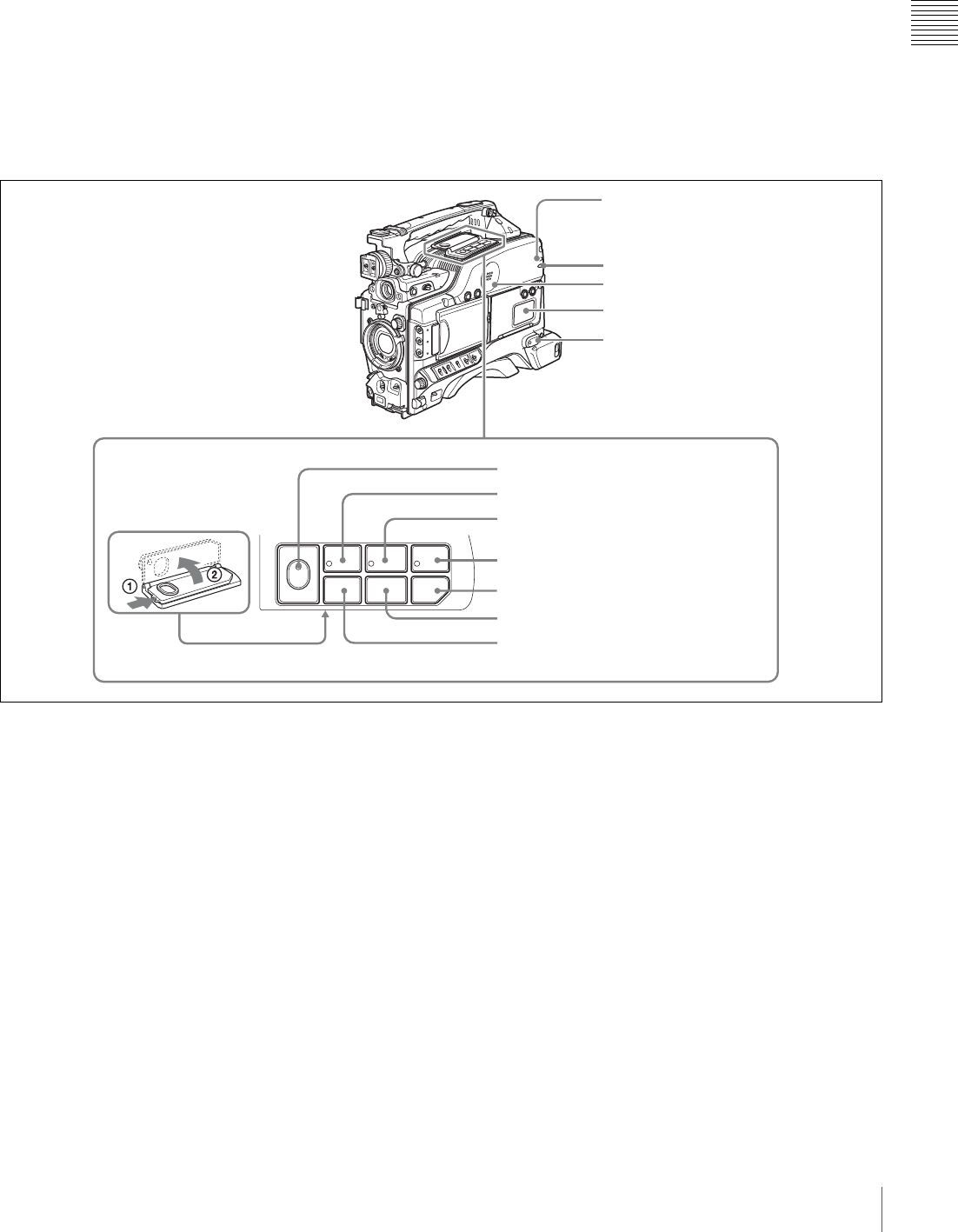
Side control panel (inside the protection cover)
aMONITOR (audio monitor selection) switches
By means of combinations of the two switches, you can
select audio that you want to hear through the built-in
speaker or optional earphones.
CH-1
MIX
CH-2
CH-3
PRESET
AUTO
FRONT
WIRELESS
REAR
CH-1
MANUAL
AUDIO SELECT
AUDIO IN
F-RUN
REGEN
ON
OFF
SET
ON
OFF
CLOCK
F
W
R
F
W
R
R-RUN
MONITOR
FRONT MIC
LOW CUT VIDEO OUT
CHARACTER
AUDIO LEVEL
THUMBNAIL SUB CLIP
MIX
CH-4
CH-1/2
CH-3/4
SHIFT
CLIP MENU
SEL/SET
0 10 0 10
ESSENCE
MARK
CH-2
CH-3
CH-4
LITHIUM BATT
1MONITOR switches
2SHIFT button
3Lithium battery compartment
4THUMBNAIL indicator
5THUMBNAIL button
6SUB CLIP indicator
9AUDIO SELECT switches
7SEL/SET button
(four-way arrow key)
8AUDIO LEVEL knobs
0AUDIO IN switches
qa VIDEO OUT CHARACTER switch
qs F-RUN/SET/R-RUN switch
qd FRONT MIC LOW CUT switch
qf PRESET/REGEN/CLOCK switch
Position of left-
side switch
Position of right-
side switch
Audio output
CH-1/CH-3 CH-1/2 Channel 1 audio
MIX Channels 1 and 2
mixed audio
(stereo) a)
CH-2/CH-4 Channel 2 audio

21
Location and Function of Parts
Chapter 1 Overview
a) By connecting stereo headphones to the EARPHONE connector you can
hear the audio in stereo. (On the AUDIO-2 page of the MAINTENANCE
menu, HEADPHONE OUT must be set to “STEREO”.)
bSHIFT button
Use this in combination with other buttons.
cLithium battery compartment
Attach the supplied CR2032 lithium battery.
Details on how to attach the lithium battery, see
“Attaching and Replacing the Lithium Battery” on
page 35.
dTHUMBNAIL indicator
This lights when thumbnails are displayed.
eTHUMBNAIL button
Press this button to carry out a thumbnail search or create
a clip list.
When pressed, the whole-screen display changes to a
thumbnail display. Press once more to return to the whole-
screen display.
For a thumbnail search using essence marks, hold down
the SHIFT button and press this button.
fSUB CLIP indicator
This lights when using a clip list for playback.
gSEL/SET (select/set) button (four-way arrow key)
Sets the timecode and user bits. Push the button towards
left or right so that the digit you want to change flashes.
Pushing the button upward increases the value of the
flashing digit, and pushing it downward decreases the
value.
Hold down the SHIFT button and press upward (in the
direction of the “SUB CLIP” legend) to display the clip
lists (when no clip list is loaded into the current clip list).
When a clip list is loaded, that clip list can be played back.
Hold down the SHIFT button and press upward once more
to exit the display of the clip lists or to exit the clip list
playback state.
Hold down the SHIFT button and press downward (in the
direction of the “CLIP MENU” legend) to display the
CLIP menu. Hold down the SHIFT button and press
downward once more to exit the CLIP menu.
When thumbnails (index frames of clips) are displayed on
the LCD monitor, you can use this button to select a
thumbnail. Push the button in four directions to move the
cursor up, down, left and right. After selecting the desired
thumbnail with the cursor, press the button centrally to
confirm.
This button is used for scene selection and other
operations.
For details of clip list playback operations, see page 86.
For details of the CLIP menu, see “Managing Clip Lists”
(page 100).
For details of scene selection, see page 90.
hAUDIO LEVEL (CH-1/CH-2) (audio channel 1/2
recording level) knobs
If the audio is input via the AUDIO IN CH-1/CH-2
connectors, adjusts the audio levels of channels 1 and 2
when the AUDIO SELECT (CH-1/CH-2) switches (see
below) are set to MANUAL.
iAUDIO SELECT (CH-1/CH-2) (audio channel 1/2
adjustment method selection) switches
Select the audio level adjustment method for each of audio
channels 1 and 2.
AUTO: Automatic adjustment
MANUAL: Manual adjustment
jAUDIO IN (CH-1/CH-2/CH-3/CH-4) (audio
channel 1/2/3/4 input selection) switches
AUDIO IN CH-1/CH-2 switches
Select the audio input signals to be recorded on audio
channels 1 and 2.
FRONT: Input signals from the microphone connected to
the MIC IN connector
WIRELESS: Audio input signals from the CA-WR855
Camera Adaptor (supplied separately) if a WRR-855
series UHF synthesized tuner (supplied separately) is
installed using the CA-WR855
REAR: Audio input signals from an audio device
connected to the AUDIO IN CH-1/CH-2 connectors
AUDIO IN CH-3/CH-4 switches
Select the audio input signals to be recorded on audio
channels 3 and 4.
F (FRONT): Input signals from a microphone connected
to the MIC IN connector
W (WIRELESS): Audio input signals from the CA-
WR855 camera adaptor (supplied separately) if a
WRR-855 series UHF synthesized tuner (supplied
separately) is installed using the CA-WR855
R (REAR): Audio input signals from an audio device
connected to the AUDIO IN CH-1/CH-2 connectors
(The signal input to the AUDIO IN CH-1 connector is
recorded on channel 3, and the signal input to the
AUDIO IN CH-2 connector on channel 4.)
CH-1/CH-3 CH-3/4 Channel 3 audio
MIX Channels 3 and 4
mixed audio
(stereo) a)
CH-2/CH-4 Channel 4 audio
Position of left-
side switch
Position of right-
side switch
Audio output
22 Location and Function of Parts
Chapter 1 Overview
For audio channels 3 and 4, level adjustment can only be
performed in AUTO (automatic) mode. The audio level of
these channels cannot be adjusted in MANUAL (manual)
mode.
kVIDEO OUT (video output) CHARACTER switch
Selects whether or not (ON/OFF) to superimpose text
information on the VIDEO OUT connector 1) output.
1) For the PDW-F330, VIDEO OUT connector on the rear panel.
lF-RUN/SET/R-RUN (free run/set/recording run)
switch
Selects the operating mode of the internal timecode
generator. The operating mode is set as explained below,
depending on the position of the switch.
F-RUN: Timecode keeps advancing, regardless of the
operating state of the VDR. Use this setting when
synchronizing the timecode with an external
timecode.
SET: Sets the timecode or user bits.
R-RUN: Timecode advances only during recording. Use
this setting to have a consecutive timecode on the
disc.
For details, see “To set the timecode” on page 66 and “To
set the user bits” on page 67.
mFRONT MIC LOW CUT switch
Set to ON to insert a high-pass filter in the microphone
circuit, reducing wind noise. Normally leave the switch in
the OFF position.
nPRESET/REGEN (regeneration)/CLOCK switch
Selects whether to set a new timecode or to utilize the
existing timecode.
PRESET: Records a new timecode.
REGEN: Records timecode continuous with the existing
timecode recorded on the disc. Regardless of the
setting of the F-RUN/SET/R-RUN switch, the
camcorder operates in R-RUN mode.
CLOCK: Records timecode synchronized to the internal
clock. Regardless of the setting of the F-RUN/SET/R-
RUN switch, the camcorder operates in F-RUN mode.
Left Side and Upper Section
aASSIGN 3/4 switches
You can assign the desired functions to these switches on
the ASSIGNABLE page of the OPERATION menu.
For details, see “Assigning Functions to ASSIGN
Switches” on page 142.
bLarge viewfinder attachment shoe
Use this to mount an optional 5-inch electronic viewfinder
(see page 43).
cViewfinder front-to-back positioning knob
Loosen this knob to adjust the front-to-back position of the
viewfinder (see page 42).
dLid of the disc compartment
This opens when the EJECT button on the top panel is
pressed. Press the side of the lid to close.
Note
1ASSIGN 3/4 switches
2Large viewfinder attachment shoe
4Lid of the disc compartment
6Shoulder strap fitting
7Viewfinder left-to-right positioning ring
8Viewfinder fitting shoe
qa MIC IN connector
9Fitting for optional microphone holder
0LIGHT connector
3Viewfinder front-to-back
positioning knob
5Accessory fitting shoe
qs Shoulder pad
1Video output and timecode connectors
23
Location and Function of Parts
Chapter 1 Overview
eAccessory fitting shoe
Attach an optional accessory such as a video light (see
page 45).
fShoulder strap fitting
Attach the supplied shoulder strap (see page 44).
gViewfinder left-to-right positioning ring
Loosen this ring to adjust the left-to-right position of the
viewfinder (see page 42).
hViewfinder fitting shoe
Attach the supplied viewfinder.
iFitting for optional microphone holder
Fit an optional CAC-12 Microphone Holder (see page 46).
jLIGHT (video light) connector (2-pin, female)
A video light with a maximum power consumption of 50
W, such as the Anton Bauer Ultralight 2 or equivalent can
be connected (see page 45).
kMIC IN (microphone input) (+48 V) connector
(XLR type, 5-pin, female)
Connect the supplied stereo microphone to this connector.
The power (+48 V) is supplied via this connector.
lShoulder pad
Raise the shoulder pad fixing lever to adjust the position in
the front-to-rear direction. Adjust the position for
maximum convenience when operating the unit on your
shoulder.
For details of the adjustment, see “Adjusting the Shoulder
Pad Position” on page 44.
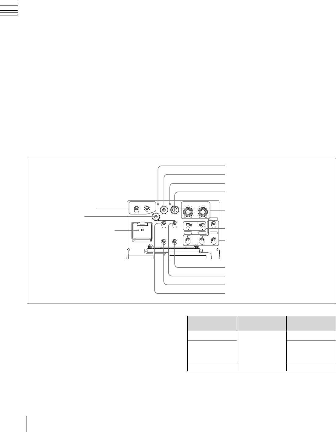
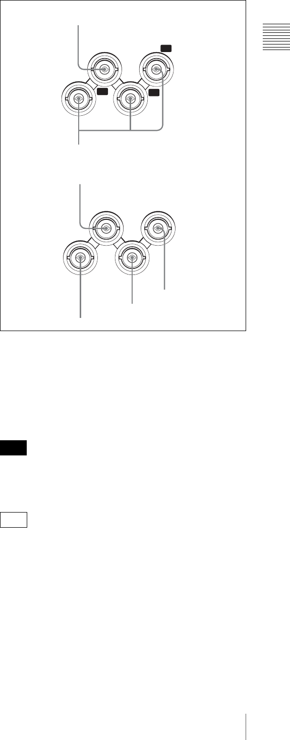
1Video output and timecode connectors
aGENLOCK IN (genlock signal input) connector
(BNC type)
Input an SD or HD reference signal when applying a
genlock to the camera, or synchronizing timecode to an
external source. Use the GENLOCK page of the
MAINTENANCE menu to carry out phase adjustment of
the horizontal synchronization signal for genlock.
The subcarrier phase cannot be adjusted.
bVIDEO OUT (video output) Y/PB/PR connectors
(BNC type)
Output component video signals (Y/PB/PR) for a video
monitor.
Connect a video monitor with component video signal
input connectors to check the video being shot by the
camera. You can also monitor VDR playback video.
You can select HD Y/PB/PR or SD Y/PB/PR signal output
on the OUTPUT page of the OPERATION menu. For
details, see “Selecting the Output Signals” on page 140.
Note
F330
GENLOCK
IN
YP
R
P
B
VIDEO
OUT
GENLOCK
IN
VIDEO
OUT
TC
OUT
TC IN
1GENLOCK IN connector
3VIDEO OUT connector
4TC OUT connector
5TC IN connector
1GENLOCK IN connector
2VIDEO OUT Y/PB/PR connectors
PDW-F330
PDW-F350
24 Location and Function of Parts
Chapter 1 Overview
Even when you are recording or playing back HD 23.98P
signals, 23.98PsF signals are not output from this
connector. The output is 59.94i signals after 2-3 pulldown.
cVIDEO OUT (video output) connector (BNC type)
Outputs a video signal for a video monitor. The output
signal is composite or HD Y. When the output signal is
composite, setting menus, timecode, or shot data can be
superimposed on the camera output video depending on
the menu settings, and you can view them on the monitor
screen. To lock the timecode of an external device to the
timecode of this unit, connect the genlock signal input
connector of the external device to this connector.
• The subcarrier phase cannot be adjusted.
• Even when you are recording or playing back HD
23.98P signals, 23.98PsF signals are not output from this
connector. The output is 59.94i signals after 2-3
pulldown.
You can select the composite or HD Y signal output on the
OUTPUT page of the OPERATION menu. For details, see
“Selecting the Output Signals” on page 140.
dTC OUT (timecode output) connector (BNC type)
To lock the timecode of an external VTR to the timecode
of this unit, connect this connector to the external VTR’s
timecode input connector.
eTC IN (timecode input) connector (BNC type)
To apply an external lock to the timecode of this unit, input
the reference timecode.
For details of timecode, see “To set the timecode” on
page 66.
Rear
aTALLY (back tally) indicator (red)
Lights up during recording. It will not light if the TALLY
switch (see below) is set to OFF. This indicator also flashes
to indicate warnings (see page 19) in the same manner as
the REC/TALLY indicator in the viewfinder.
For details, see “Operation Warnings” on page 165.
bTALLY switch
Set to ON to activate the TALLY indicator (see above)
function.
cBattery attachment shoe
Attach a BP-GL95/GL65/L60S/L80S Battery Pack.
Alternatively, you can attach an AC-DN2B/DN10 AC
Adaptor to operate the camcorder on AC power supply.
For details about how to attach the battery or AC adaptor,
see “Preparing a Power Supply” on page 36. For
information about attaching a synthesized tuner, see
“Attaching a UHF Synthesized Tuner” on page 47.
For your safety, and to ensure proper operation of the
camcorder, Sony recommends the use of the following
battery packs: BP-GL95, BP-GL65, BP-L60S, and BP-
L80S.
dWRR connector (7-pin)
Connect a CA-WR855 Camera Adaptor with attached
WRR-855 UHF Synthesized Tuner.
For details, see “Attaching a UHF Synthesized Tuner” on
page 47.
Note
F350
Notes
F350
F350
Note
1TALLY indicator
2TALLY switch
3Battery attachment
shoe
4WRR connector
1Connector panel
!"##$%&'#$()*
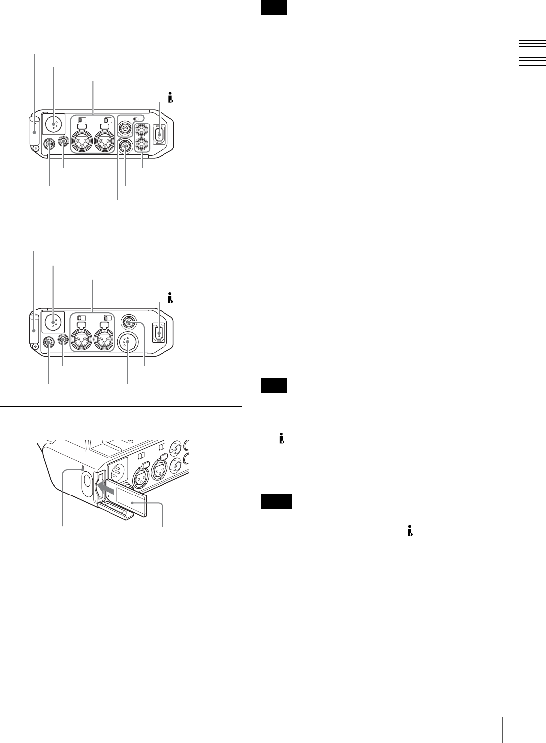
25
Location and Function of Parts
Chapter 1 Overview
1Connector panel
a“Memory Stick” slot
Insert a “Memory Stick”. The “Memory Stick” access
indicator lights up when the “Memory Stick” is being
accessed for reading or writing.
For details about how to insert a “Memory Stick”, see “To
insert a “Memory Stick”” on page 146.
For details about the types of “Memory Stick”, see “About
a “Memory Stick”” on page 174.
Do not remove a “Memory Stick” while the “Memory
Stick” access indicator is lit. Doing so may cause a loss of
data.
bDC IN (DC power input) connector (XLR type, 4-
pin, male)
To operate the camcorder using an AC power supply,
connect an AC-550 AC Adaptor with the DC output cable
supplied with the adaptor.
cAUDIO IN CH-1/CH-2 (audio input channel 1/2)
connectors (XLR type, 3-pin, female) and input
selection switches
Connect other audio equipment or external microphone.
Set the input selection switches as shown below according
to the microphone or equipment.
LINE (left position): For connecting an external audio
signal source such as a stereo amplifier
MIC (center position): For connecting any microphone
other than 48 V microphone
MIC +48V ON (right position): For connecting a 48 V
microphone
Signals input to the AUDIO IN CH-1 connector can be
recorded on audio channels 1 and 3. Similarly, signals
input to the AUDIO IN CH-2 connector can be recorded on
audio channels 2 and 4. 1)
1) When the AUDIO IN (CH-1/CH-2/CH-3/CH-4) switches on the side
control panel are set to “REAR” or “R”.
If MIC +48V ON is selected for a microphone other than
48 V microphone, the microphone may be damaged.
d(i.LINK) DV OUT S400 connector (6-pin, IEEE
1394 compliant)
Connect to a device supporting the DV format or a
computer, using an i.LINK cable (DV cable).
• If video and audio signals are not output from the
external device connected to the (i.LINK) DV OUT
S400 connector, disconnect the i.LINK cable (DV cable)
and then reconnect it, making sure that it is firmly seated.
• When you connect the camcorder and other equipment,
such as a hard disk drive, with an i.LINK interface to a
computer with i.LINK connectors, turn off the power of
the computer, the other equipment, and the camcorder
before connecting them using the i.LINK cable (DV
cable). If a bus-powered type 1) hard disk drive or similar
equipment is connected while the computer is powered
on, electric current flows into the camcorder because of
the high voltage caused by the load shift of the computer
power, and this may cause a malfunction.
1”Memory Stick” slot
2DC IN connector
3AUDIO IN CH-1/CH-2 connectors and
input selection switches
1“Memory Stick” slot
2DC IN connector
3AUDIO IN CH-1/CH-2 connectors and
input selection switches
5REMOTE
connector
6DC OUT 12V
connector
7TC connector and IN/OUT
selector switch
8VIDEO OUT connector
9AUDIO OUT CH-1/CH-2
connectors
5REMOTE
connector
6DC OUT 12V
connector
0AUDIO OUT connector
qa HDSDI OUT connector
PDW-F330
PDW-F350
4DV OUT S400
connector
4DV OUT S400
connector
“Memory Stick”
access indicator “Memory Stick”
Note
Note
Notes

26 Location and Function of Parts
Chapter 1 Overview
1) Equipment that can be powered through i.LINK cable (DV cable)
eREMOTE connector (8-pin)
Connect an RM-B150/B750 Remote Control Unit, which
makes it possible to control the camcorder remotely.
Before connecting/disconnecting the Remote Control Unit
to/from the camcorder, be sure to turn off the camcorder
POWER switch.
fDC OUT 12V (DC power output) connector (4-pin,
female)
Supplies power for a WRR-861/862 UHF Synthesized
Tuner (optional) (maximum 0.2 A).
Do not connect any equipment other than the UHF
synthesized tuner.
gTC (timecode) connector (BNC type) and IN/OUT
selector switch
• IN/OUT selector switch: IN
To apply an external lock to the timecode, input the
reference timecode.
• IN/OUT selector switch: OUT
To lock the timecode of an external VTR to the timecode
of this unit, connect this connector to the external VTR’s
timecode input connector.
hVIDEO OUT connector (BNC type)
Outputs a video signal for a video monitor. When the
output signal is composite, setting menus, timecode, or
shot data can be superimposed on the camera output video
depending on the menu settings, and you can view them on
the monitor screen. To lock the timecode of an external
device to the timecode of this unit, connect the genlock
signal input connector of the external device to this
connector.
The subcarrier phase cannot be adjusted.
iAUDIO OUT CH-1/CH-2 (audio output channel 1/
2) connectors (RCA phono jacks)
Output the audio singnals being recorded or played back.
Connect to a stereo amplifier or video monitor’s audio
input connectors.
jAUDIO OUT connector (XLR type, 5-pin, male)
Output the audio signals recorded on audio channels 1 and
2 or audio channels 3 and 4. The audio signals are selected
by the MONITOR switch.
kHDSDI OUT connector (BNC type)
Outputs an HDSDI signal (supporting the embedded audio
function).
Connect a video monitor with an HDSDI signal input
connector to check the video being shot by the camera.
You can also monitor VDR playback video.
• Even when you are recording or playing back HD
23.98P signals, 23.98PsF signals are not output from this
connector. The output is 59.94i signals after 2-3
pulldown.
• When the video recorded in the DVCAM format is
played back, no signal is output.
Note
F330
F330
Note
F330
F350
F350
Notes
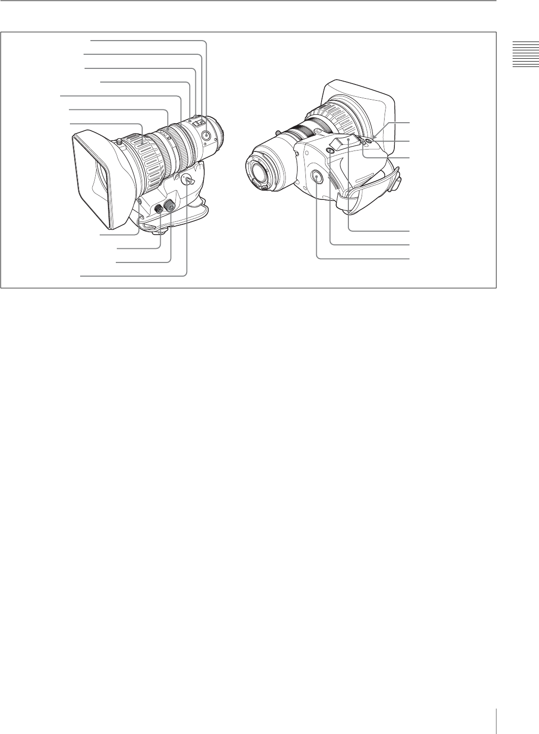
27
Location and Function of Parts
Chapter 1 Overview
VCL-719BXS Auto Focus Lens (Supplied With the PDW-F330K)
aPUSH AF (auto focus) button
When the focus adjustment is in the manual mode, by
pressing this button you can use the auto focus for an
instantaneous adjustment to the subject.
When the button is pressed, the auto focus operates until
the image is in focus, then disengages.
Even when the FOCUS switch is set to A (auto), by
pressing this button, you can restart the auto focus.
bFOCUS switch
Select the method of focusing.
A (auto): The auto focus function is constantly active.
While the auto focus is operating, the auto focus
indicator lights green. Even with the switch in the A
position, you can manually adjust the focus by
operating the focus ring.
M (manual): The manual mode allows focusing
adjustment with the focus ring.
In manual mode, auto focus adjustment is also
possible, by pressing the PUSH AF button.
cMACRO switch
When this switch is in the ON position, the macro mode is
enabled, allowing focusing over the whole range (5 cm 1)
to !) including the macro range (from 5 cm 1) to 90 cm
from the front of the lens).
This operation is independent of whether the focus
adjustment mode is auto or manual.
In the macro range, the auto focusing speed is lower.
1) At the wide-angle setting
dAuto focus indicator
This lights green while the auto focus function is
operating.
During flange focal length adjustment, it flashes orange or
green.
If an error occurs, it lights red.
For details of flashing during flange focal length
adjustment, see “Adjusting the Flange Focal Length” on
page 40.
eIris ring
For manual iris adjustment, set the IRIS switch to the M
(manual) position, then turn this ring.
fZoom ring
For manual zoom adjustment, set the ZOOM switch to the
MANU. position, then turn this ring.
gFocus ring
Turn this ring to adjust the focus.
This ring can be turned endlessly in both directions. The
faster you turn, the faster the focusing mechanism
operates, to minimize the amount of turning required for
focusing.
hFlange focal length adjustment button
Press this to adjust the flange focal length (the distance
from the lens mounting flange plane to the focusing plane).
For details of flange focal length adjustment, see
“Adjusting the Flange Focal Length” on page 40.
1PUSH AF button
2FOCUS switch
3MACRO switch
4Auto focus indicator
5Iris ring
6Zoom ring
9Focus control connector
7Focus ring
8Flange focal length
adjustment button
0Zoom control connector
qa ZOOM switch
qs IG control
qd IRIS button
qf IRIS switch
qg Power zoom lever
qh RET button
qj REC button

28 Location and Function of Parts
Chapter 1 Overview
iFocus control connector (6-pin)
Connecting an optional focus servo controller allows
remote control of focusing.
jZoom control connector (8-pin)
Connecting an optional zoom servo controller allows
remote control of zooming.
kZOOM switch
Select the method of zoom operation.
SERVO: Power zoom. Operate the zoom with the power
zoom lever.
MANU. (manual): Manual zoom. Operate the zoom with
the zoom ring.
lIG (iris gain) control
Remove the rubber cap, and turn the knob inside, to adjust
the gain for auto iris adjustment.
This is set to an appropriate value when the unit is shipped.
It does not normally require any adjustment.
mIRIS button
When the IRIS switch is in the M position for manual
adjustment, press this button for an instantaneous auto
adjustment.
The iris is automatically adjusted while the button is held
down.
nIRIS switch
Select the method of iris adjustment.
A (auto): Auto mode. The iris is adjusted automatically.
M (manual): Manual mode. Adjust the iris with the iris
ring.
oPower zoom lever
This is enabled when the ZOOM switch is in the SERVO
position. Press the W end for wide-angle and the T end for
telephoto.
Press the lever harder for a faster zoom action.
Notes on auto focus
• When an auto focus lens is mounted, in the auto focus
mode a frame appears in the center of the viewfinder
screen indicating the auto focus area. Place the subject
on which you want to focus within this frame.
• In the following cases, it may be difficult to focus on the
subject. If this does happen, use manual focusing.
- If the subject has no contrast
- If the subject is moving rapidly
- When shooting point light sources, under street
lighting or at night
- When there are very bright objects close to the subject
- When shooting through a glass window
• On the LENS page of the MAINTENANCE menu, by
changing the AF DETECT AREA setting from
“CENTER” to “FULL”, instead of focusing only on the
center portion of the screen, the whole screen image is
used for focusing. In this case, the auto focus area frame
does not appear.
• If there are a number of objects within the screen at close
and far range, the focus may not be on the intended
subject. In this case, with the subject on which you want
to focus in the center of the screen, press the PUSH AF
button.
• After focusing with the PUSH AF button, if you operate
the zoom or adjust the iris, the depth of field may
become shallower, losing crisp focus. In such cases,
press the PUSH AF button once more.
• If you focus at wide-angle then zoom to telephoto, the
subject may no longer be in focus.
• The auto focus function does not operate while using the
slow shutter mode (4F or higher).
Note on zoom speed
Depending on the shooting distance, the zoom speed may
fall as the lens approaches the telephoto end.
pRET (return video) button
Use this to check the video. If you press this while the
internal VDR is pausing recording, the last few seconds
recorded appear in the viewfinder (a recording review
operation).
For details, see “Checking the Last Two Seconds of the
Recording (a Recording Review Operation)” on page 81.
Pressing this button (single click) during recording records
a shot mark 1, and double-clicking records a shot mark 2.
For details, see “Recording Shot Marks” on page 70.
qREC (record) button
Use this to start and stop recording. Press once to start
recording, then press once more to stop.
Note
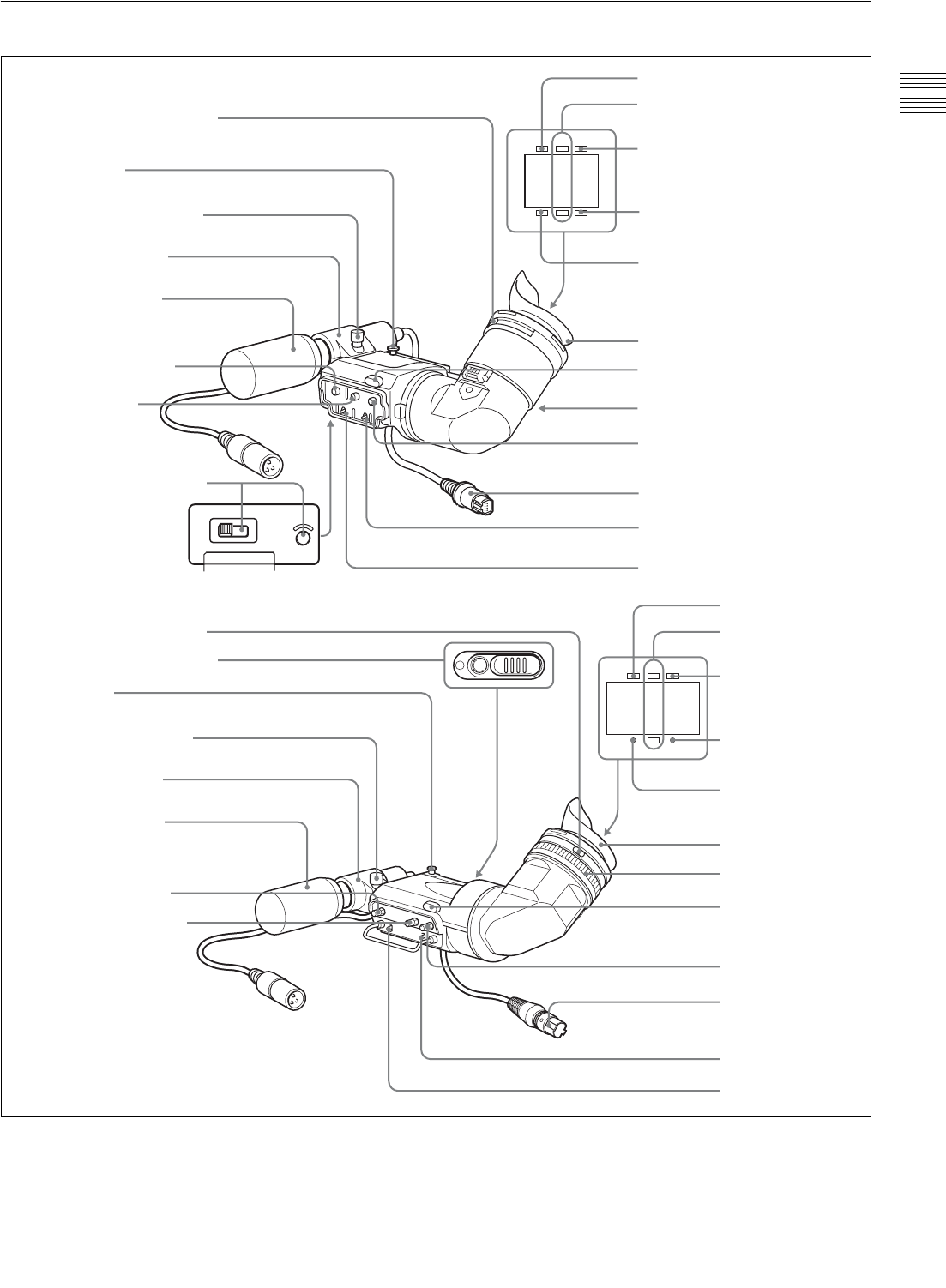
29
Location and Function of Parts
Chapter 1 Overview
Viewfinder
HIGH LOW OFF
LIGHT
SHUTTER GAIN UP
BATTREC
TALLY
SHUTTER GAIN UP
BATTREC
TALLY
1Eyepiece focusing knob
3Stopper
4PEAKING control
5
CONTRAST
control
6LIGHT switch and light
7TALLY indicator
0GAIN UP indicator
8REC/TALLY indicators
9BATT indicator
qa SHUTTER indicator
qd Tally light
qf Eyepiece release catch
qg BRIGHT control
qh Viewfinder connector
qj TALLY switch
Eye cup
qk DISPLAY switch
Microphone fixing screw
Microphone holder
Stereo microphone
(packaged with
camcorder)
DXF-801/801CE (supplied with the PDW-F330)
DXF-20W (supplied with the PDW-F350)
1Eyepiece focusing ring
2Camera person tally light
3Stopper
Microphone holder
4PEAKING control
5CONTRAST control
7TALLY indicator
8REC/TALLY
indicators
9BATT indicator
0GAIN UP indicator
qa SHUTTER indicator
Eye cup
qs Lock ring
qd Tally light
qg BRIGHT control
qh Viewfinder
connector
qj TALLY switch
qk DISPLAY switch
Microphone fixing screw
Stereo microphone
(packaged with
camcorder)

30 Location and Function of Parts
Chapter 1 Overview
aEyepiece focusing knob (DXF-801/801CE)
Eyepiece focusing ring (DXF-20W)
Adjusts the viewfinder focus to match your eyesight (see
page 42).
bCamera person tally light (DXF-20W)
Lights while the camcorder is recording. To start recording
with your eye off the viewfinder, open the slide window.
This indicator flashes when the remaining battery capacity
or remaining disc capacity is low.
cStopper
Lift up when detaching the viewfinder (see page 42).
dPEAKING control
Adjusts the outline intensity of the viewfinder image (see
page 42).
eCONTRAST control
Adjusts the contrast of the viewfinder image (see page 42).
fLIGHT switch and light (DXF-801/801CE)
The light lights the lens and the switch controls the light as
follows.
HIGH: Brighter
LOW: Darker
OFF: Turns the light off.
gTALLY (tally) indicator (green)
Flashes when the camcorder is in Interval Rec mode.
Flashing quickens while you are shooting in Interval Rec
mode.
For details on Interval Rec mode, see “Time-lapse Video
Recording (“Interval Recording” Function)” on page 71.
hREC/TALLY (recording/tally) indicators (red)
Function as follows.
• Begin flashing when you press the REC button on the
camcorder or on the lens until recording starts, then stay
on continuously during recording.
• Indicate a fault (see page 165).
On the CAM CONFIG page of the MAINTENANCE
menu, you can select that the lower indicator also lights.
iBATT (battery) indicator (red)
Lights up when the remaining battery capacity is low.
jGAIN UP indicator (orange)
Lights up when the gain is 3 dB or more.
kSHUTTER indicator (red)
Lights up when the SHUTTER switch (page 14) is ON.
lLock ring (DXF-20W)
If you want to directly view the viewfinder screen, rotate
this ring counterclockwise to align the matching marks (in
orange) on the lock ring and the viewfinder cylinder part to
each other, and then remove the eyepiece.
mTally light
When the TALLY switch (see below) is in the ON
position, this operates in the same way as the REC/TALLY
indicators.
nEyepiece release catch (DXF-801/801CE)
To view the viewfinder screen directly, press to hinge up
the eyepiece.
oBRIGHT (brightness) control
Adjusts the brightness of the viewfinder image (see page
42).
pViewfinder connector (20-pin)
Connect to the VF connector (see page 13).
qTALLY switch
Set to the HIGH (high-intensity) or LOW (low-intensity)
to use the tally light.
rDISPLAY switch
Set to ON when you want to display text information on
the viewfinder screen.
F350
F330
F350
F330
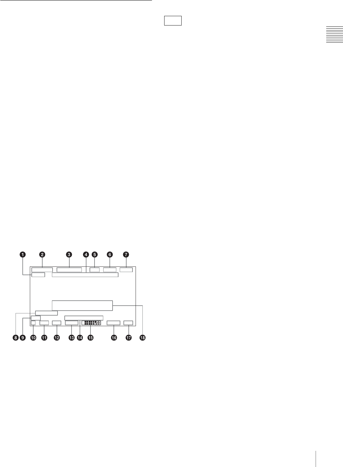
31
Location and Function of Parts
Chapter 1 Overview
Status Display on the Viewfinder
Screen
The viewfinder screen displays not only the video picture
but also characters and messages indicating the camcorder
settings and operating status, a center marker, a safety zone
marker, etc.
When the menu screen is not displayed and the DISPLAY
switch is set to ON, the items for which an ON setting was
made on the VF DISP 1 or VF DISP 2 page of the
OPERATION menu or with related switches are displayed
at the top and bottom of the screen.
The messages that give details of the settings and
adjustment progress and results can also be made to appear
for about 3 seconds while settings are being changed,
during adjustment, and after adjustment.
For details about the display item selection, see “Selecting
the Display Items” on page 136.
For details about setting change and adjustment progress
messages, see “Change Confirmation/Adjustment
Progress Messages” on page 137.
For details about marker display, see “Setting the Marker
Display” on page 137.
Layout of the status display on the
viewfinder screen
All items that can be displayed on the viewfinder screen
are shown below.
aVDR operation indicators
VDR operation is displayed as follows:
REC: During recording
PLAY: During playback
X: During pause of recording/playback
M: During high-speed playback or forward jump to clips
m: During reverse high-speed playback or reverse jump
to clips
bRecording format
Indicates the current recording format.
cFrame frequency
Indicates the current frame frequency.
When using the slow & quick-motion function, the
playback frame frequency appears with the shooting frame
frequency in square brackets (two-digit whole number,
with decimal fractions rounded).
During normal playback, the square brackets and included
value do not appear.
dTimecode
Indicates the elapsed recording/playback time, timecode,
user bits or other information selected by the DISPLAY
switch (see page 30).
eZoom position
Indicates the zoom position of the zoom lens in the range
from 0 to 99.
fFocus
Indicates the focusing distance corresponding to the focus
ring when an auto focus lens is mounted, and the focus
adjustment mode is set to manual.
The displayed resolution is as shown below.
• 10 m or less (including the macro area): 0.1 m
• 10 m to 100 m: 1 m
• 100 m to 200 m: 10 m
• 200 m to infinite distance: 50 m
gDC IN/battery voltage/remaining battery capacity
Indicates the battery voltage or the remaining capacity of
an attached internal battery pack, an AC adaptor, or an
external battery (a battery connected to the DC IN
connector).
When the power is supplied from an external battery, “DC
IN” appears here.
When the DISP BATT REMAIN item is set to “INT” on
the VF DISP 1 page of the OPERATION menu, the battery
voltage is not indicated.
However, when the Anton Bauer intelligent battery system
or the BP-GL95/GL65 Battery Pack is used, the remaining
battery capacity is automatically detected and indicated in
steps of 10%.
• Until the remaining battery capacity is reduced to 40%,
the indications MAX, 90%, 80%...40% are displayed for
three seconds in the viewfinder each time the remaining
battery capacity reduces by 10%.
• When the remaining battery capacity is less than 40%,
the indication is displayed all the time.
• When the remaining battery capacity is less than 10%,
the indication flashes. When the remaining battery
capacity is reduced further, the “LOW” flashes.
hClip list name
Displays the name (E0001 to E0099) of the currently
selected clip list.
1 A F-
H D S P P [ ] Z 1 m V
2823 .9
W:
18 dB 1/ 20 00 30 F1 .6
.599 13 .4
REC TCG 0:30:11:03
W H I T E : N G
LEVEL TOO HIGH
E 0 0 9 9
LOW LIGHT
1
2
56 00
F350

32 Location and Function of Parts
Chapter 1 Overview
i5600 indicator
Appears when the electric color temperature filter function
is on.
jFilter
Indicates the currently selected filter type.
kWhite balance memory
Indicates the currently selected white balance automatic
adjustment memory.
A: Displayed when the WHITE BAL switch is set to A.
B: Displayed when the WHITE BAL switch is set to B.
P: Displayed when the WHITE BAL switch is set to PRST
or when the preset button on an RM-B150 has been
pushed.
T: Displayed when ATW is being used.
lGain value
Indicates the gain value (in dB) of the video amplifier, as
set by the GAIN switch.
mShutter speed
Indicates the shutter speed or the shutter mode. However,
if the SHUTTER switch (see page 14) is set to OFF,
nothing is displayed.
For details of the displayed shutter speed, see “Setting the
Electronic Shutter” on page 62.
nOperation/alarm message display area
For details, see “Operation/alarm messages” on
page 166.
oAudio level
Indicates the level of audio channel 1 and channel 2. The
peak indication of the VDR level meter is related as
follows to the audio level when an 1 kHz sine wave is
input.
pRemaining disc capacity
Indicates the remaining recording time (in minutes) of the
disc.
Examples of remaining recording time indication
qIris setting/auto iris override
Indicates the F value (iris setting) of the lens.
Also, the auto iris override is displayed using two squares
which appear in the upper and lower parts respectively.
For details, see “Adjusting the Iris” on page 64.
rSetting change and adjustment progress message
display area
For details, see “Change Confirmation/Adjustment
Progress Messages” on page 137.
RM-F300 Infrared Remote Commander
To use the infrared remote commander, it is necessary to
assign the remote commander enabling/disabling function
to an ASSIGN switch, and then press the ASSIGN switch
to enable the remote commander. (This function is factory
preset to the ASSIGN 2 switch.)
For details of how to assign a particular function to an
ASSIGN switch , see page 142.
Indication Remaining recording time
90 < More than 90 minutes
90 - 85 90 to 85 minutes
85 - 80 85 to 80 minutes
.
.
.
.
.
.
20 - 15 20 to 15 minutes
15 - 10 15 to 10 minutes
10 - 5 10 to 5 minutes
5 - 0 5 to 0 minutes
No display 0 minute
A
udio channel 1 level indicator
A
udio channel 2 level indicator
VDR level meter indicator

33
Location and Function of Parts
Chapter 1 Overview
aZOOM T/W (telephoto/wide-angle) buttons
Use these when a zoom lens is mounted.
Press W to zoom in the wide-angle direction, and T to
zoom in the telephoto direction.
bSHOT MARK 1/2 buttons
Press these during recording or playback to record a shot
mark 1 or shot mark 2.
These are only effective when SHOT MARK 1/2 is set to
ON on the ESSENCE MARK page of the
MAINTENANCE menu.
cSUB CLIP button
Press this to carry out a scene selection setting.
dTHUMBNAIL button
Press this button to carry out a thumbnail search or create
a clip list.
When pressed, the whole-screen display changes to a
thumbnail display. Press once more to return to the whole-
screen display.
ePREV (previous) button
This jumps to the start of the current clip, then pauses.
fF REV (fast reverse) button
This plays back at high speed in the reverse direction.
gPLAY/PAUSE button
Press this button to view playback video.
Press this button again during playback to pause.
hREC (record) button
Hold down the unmarked button, and press the z button to
start recording.
iREC PAUSE (recording pause) button
Hold down the unmarked button, and press the X button to
pause recording.
jPUSH SET button (four-way arrow key)
When thumbnails (index frames of each clip) are displayed
on the LCD monitor, you can use this button to select a
thumbnail.
Press the button in four directions to move the cursor up,
down, left and right. After selecting the desired thumbnail
with the cursor, press the button centrally to confirm.
kNEXT button
This jumps to the start of the next clip, then pauses.
lSTOP button
Press this to stop disc playback.
mF FWD (fast forward) button
This plays back at high speed in the forward direction.
nPUSH AF (auto focus) button
Use this when an auto focus lens is mounted.
When the button is pressed, the auto focus operates until
the image is in focus, then disengages.
Using the infrared remote commander
Before use
Pull out the insulation sheet.
Replacing the lithium battery in the remote
commander
Use a CR2025 lithium battery as power source for the
remote commander. Do not use any battery other than
CR2025.
1
2
T
ZOOM
PUSH SET
SHOTMARK
SUB CLIP
THUMBNAIL
PLAY/PAUSE
STOP
PUSH AFREC PAUSE
REC
W
.
m
z
>
M
X
xu
FFWDFREV
PREV NEXT
1ZOOM T/W buttons
2SHOT MARK 1/2
buttons
4THUMBNAIL button
5PREV button
6F REV button
7PLAY/PAUSE button
8REC button
0PUSH SET button (four-way arrow key)
qa NEXT button
qs STOP button
qd F FWD button
qf PUSH AF button
3SUB CLIP button
9REC PAUSE button
Insulation sheet

34 Location and Function of Parts
Chapter 1 Overview
1
Hold down the lock lever (1), and then pull out the
battery holder (2).
2
Put a new battery in the battery holder with the +
symbol facing upward (1), and then push in the
battery holder until it clicks (2).
Battery may explode if mistreated.
Do not recharge, disassemble or dispose of in fire.
Danger of explosion if battery is incorrectly replaced.
Replace only with the same or equivalent type
recommended by the manufacturer.
Dispose of used batteries according to the manufacturer’s
instructions.
Battery lifetime
When the lithium battery output falls, even button presses
may not operate. The average lithium battery lifetime is
about one year, but this depends on the pattern of use.
If pressing the remote control buttons produces absolutely
no effect on this unit, replace the battery, then check the
operation again.
WARNING
CAUTION
1
2
1
2
Face the + symbol upward.
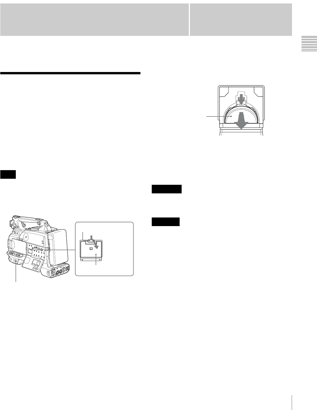
35
Attaching and Replacing the Lithium Battery
Chapter
Chapter 2 Preparations
2
Preparations
Attaching and Replacing
the Lithium Battery
This camcorder uses a lithium battery to retain stored data.
When using the camcorder for the first time, be sure to
attach the supplied lithium battery (CR2032). The
camcorder will not operate correctly without this lithium
battery. After attaching the lithium battery, set the date and
time of the internal clock (see “Setting the Date and Time
of the Internal Clock” on page 39).
Use CR2032 lithium batteries only. Other types of lithium
battery may come loose when the camcorder is subjected
to vibrations. If you have difficulty finding CR2032
lithium batteries, contact your Sony dealer.
1
Set the POWER switch to OFF.
2
Press down the catch at the top of the battery cover and
open the cover.
3
Take out the lithium battery.
4
Reverse step 3 to insert a replacement lithium battery.
Make sure that the + symbol on the battery is facing
you.
5
Close the battery cover.
Battery may explode if mistreated.
Do not recharge, disassemble or dispose of in fire.
Danger of explosion if battery is incorrectly replaced.
Replace only with the same or equivalent type
recommended by the manufacturer.
Dispose of used batteries according to the manufacturer’s
instructions.
Bei der Entsorgung leerer Batterien sind die Anweisungen
des Herstellers zu befolgen.
Service life of the lithium battery
When the lithium battery’s voltage falls, the lithium
battery low voltage warning appears on the LCD monitor
(see page 17). If this warning appears, replace the lithium
battery (CR2032) within three or four days.
The lithium battery has an average service life of about one
year.
Note
LITHIUM BATT
2
1
Catch
Press down
and pull
forward.
Battery cover
WARNING
CAUTION
Press down and pull out
toward you.
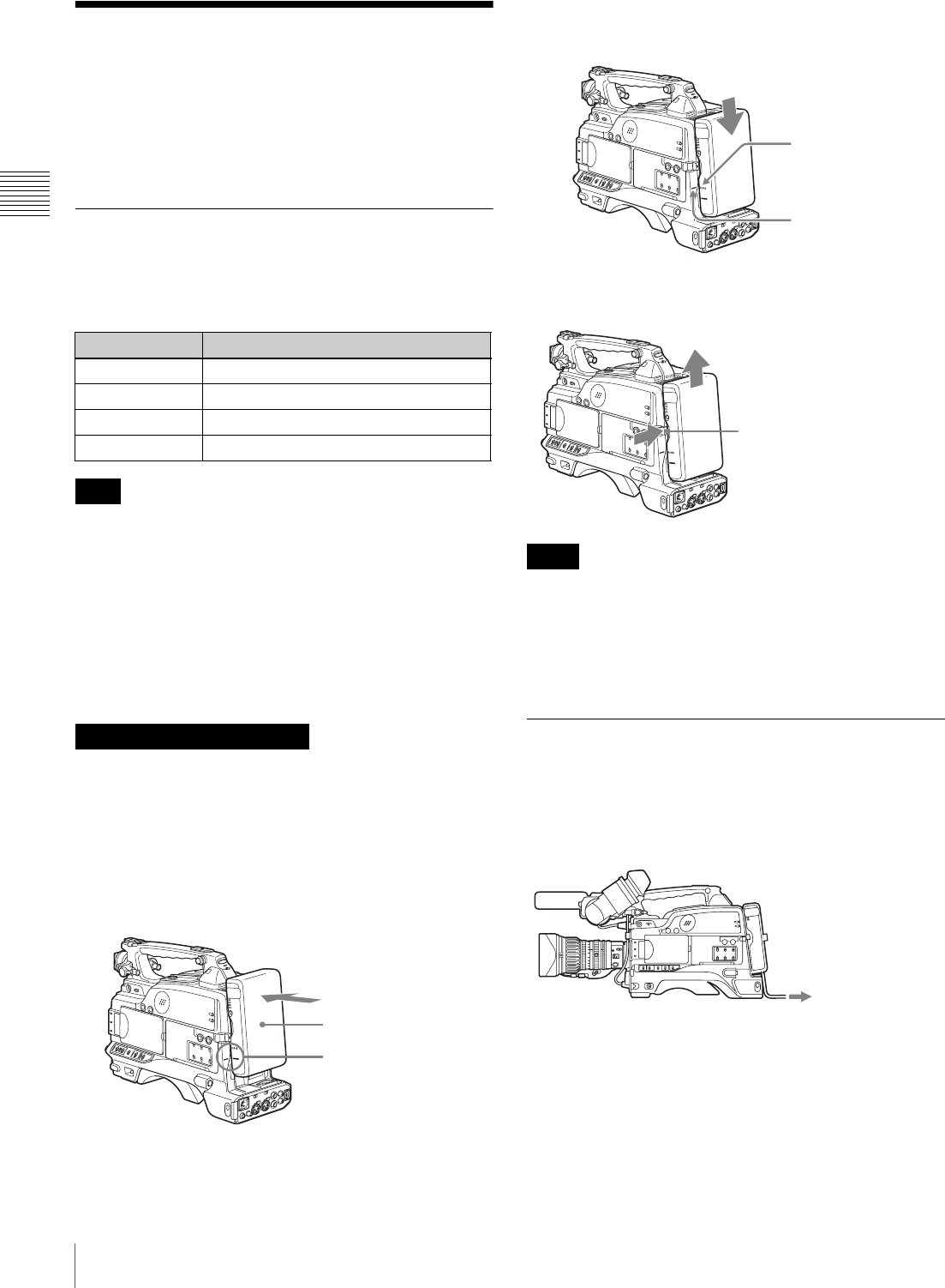
36 Preparing a Power Supply
Chapter 2 Preparations
Preparing a Power Supply
The following power supplies are recommended for the
camcorder.
• BP-GL95/GL65/L60S/L80S Lithium-ion Battery Pack
• AC power using the AC-DN2B/DN10 AC adaptor
Using a Battery Pack
When a BP-GL95/GL65/L60S/L80S Battery Pack is used,
the camcorder will operate continuously for the time
shown below.
The battery pack operating time depends on the frequency
of use of the battery pack, and the ambient temperature
when used.
Before use, charge the battery pack with a charger suitable
for each battery.
For details on the battery charging procedure, refer to the
battery charger operation manual.
A warm battery pack may not be able to be fully recharged.
To attach the battery pack
1
Press the battery pack against the back of the
camcorder, aligning the line on the side of the battery
pack with the matching line on the camcorder.
2
Slide the battery pack down until its “LOCK” arrow
points at the matching line on the camcorder.
To detach the battery pack
• During recording and playback (while the ACCESS
indicator is lit), be careful never to remove the battery
pack.
• Make sure to power the camcorder off before replacing
the battery pack.
Using an AC Adaptor
When using the AC-DN10 AC adaptor
Mount an AC-DN10 on the camcorder in the same way as
a battery pack, then connect to the AC power supply.
The AC-DN10 can supply up to 100 W of power.
Model name Operating time
BP-GL95 Approx. 160 minutes
BP-GL65 Approx. 100 minutes
BP-L60S Approx. 100 minutes
BP-L80S Approx. 130 minutes
Note
Note on using the battery pack
BP-GL95/GL65/L60S/L80S
Back of the camcorder
Align these lines.
Notes
“LOCK” arrow
Matching line on the
camcorder
Holding this button in, pull
the battery pack up.
to an AC power source
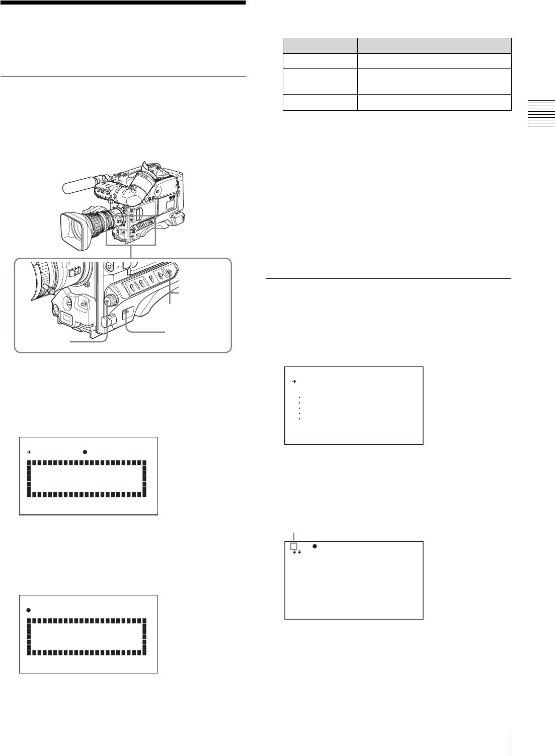
37
Setting the Area of Use and the Frame Frequency
Chapter 2 Preparations
Setting the Area of Use
and the Frame Frequency
Using the Unit for the First Time
The area of use and the frame frequency are not factory
preset. Before using this unit, you need to set these items.
(You cannot use the unit without setting these items.)
1
Set the POWER switch to the ON position.
The screen for setting the area of use appears in the
viewfinder.
2
Press the MENU knob.
The z mark on the left of “NOT SELECTED”
changes to a ? mark, and you can now select the area
of use.
3
Turn the MENU knob to display the desired area of
use.
a) The composite signal output from this unit is an NTSC signal with no
Setup. The frame frequency can be selected as any of 60I, 30P, or
23.98P.
b) The composite signal output from this unit is an NTSC signal with
Setup (7.5 IRE). The frame frequency can be selected as any of 60I,
30P, or 23.98P.
c) The composite signal output from this unit is a PAL signal. The
frame frequency can be selected as either 50I or 25P.
4
Set the POWER switch to OFF, then once again to ON.
The unit is now ready for use.
Proceed to the next operation: setting the frame
frequency (see below).
Setting the Frame Frequency
1
Hold down the MENU knob, and move the MENU
switch to the ON position.
The TOP menu appears.
2
Turn the MENU knob to move the b mark to
“OPERATION”, then press the MENU knob.
The CONTENTS page of the OPERATION menu
appears.
3
Press the MENU knob, then turn the knob to move the
b mark to “FORMAT”.
4
Press the MENU knob.
MENU switch
POWER switch
MENU knob
C OUNTR Y : NOT SE LE CT ED
PLEA SE S ET CO UN TR Y
AND TU RN OFF ON CE .
FORM AT S ETTIN G
C OUNTR Y : ?NOT SE LE CT ED
PLEA SE S ET CO UN TR Y
AND TU RN OFF ON CE .
FORM AT S ETTIN G
Setting Area of use
NTSC (J) AREA NTSC area (Japan) a)
NTSC AREA NTSC area (for areas other than
Japan) b)
PAL AREA PAL area c)
USER
U SER M EN U CUSTO MI ZE
ALL
OPERA TI ON
PAINT
MAINT EN AN CE
FILE
DIAGN OS IS
<T OP M ENU>
0 01.FO RM AT
0 02.SP EC IA L EFF EC TS
0 03.AS SI GN ABLE
0 04.DI SC
0 05.CL IP T ITLE
0 06.FI LE N AMING
0 07.GA IN S W
0 08.EZ M OD E/TLC S
0 09.OF FS ET WHIT E
0 10.VI DE O OUT
TO P?0 00 CO NT EN TS
You can move to another page when a ? mark appears.
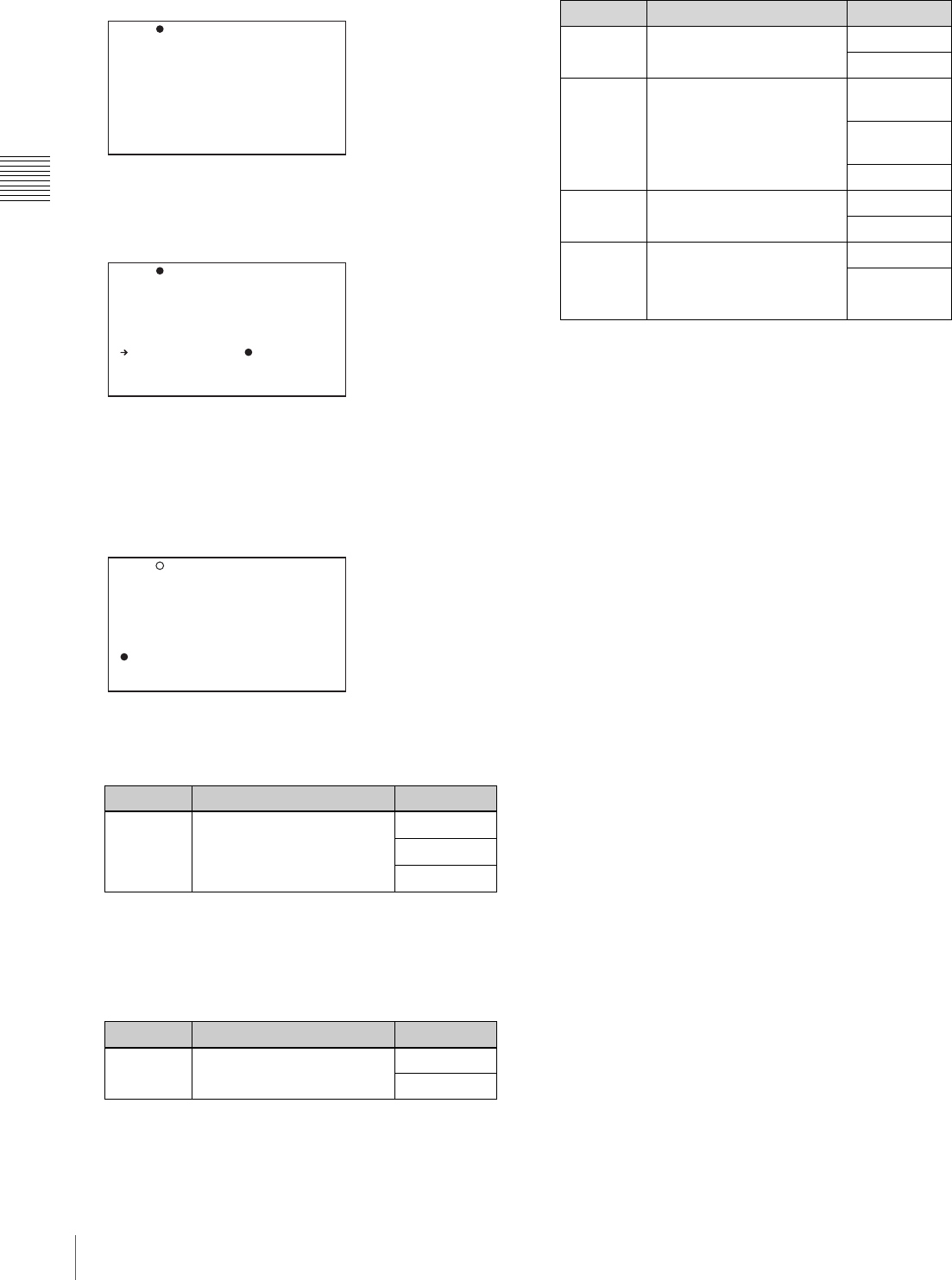
38 Setting the Area of Use and the Frame Frequency
Chapter 2 Preparations
The FORMAT page appears.
5
To change the area of use, press and turn the MENU
knob to move the b mark to “COUNTRY”, then press
the MENU knob.
The b mark beside “COUNTRY” changes to a z
mark, and the z mark beside the setting value changes
to a ? mark.
6
Turn the MENU knob to display the desired area of use
(see step 3 in the previous section).
7
Refer to steps 5 and 6, and select the frame frequency.
If NTSC (J) AREA/NTSC AREA has been selected
a) More precisely 59.94I.
b) More precisely 29.97P.
c) More precisely 23.98P.
If PAL AREA has been selected
8
Refer to steps 5 and 6, and set the recording format and
other items as required.
9
Set the POWER switch to OFF, then once again to ON.
Item Description Setting
SYSTEM Set the frame frequency. 60I a)
30P b)
23.9P c)
Item Description Setting
SYSTEM Set the frame frequency. 50I
25P
S YSTEM : 6 0I
R EC FO RM AT :M PE G HD
B IT RA TE (HD) : SP
A UDIO CH (HD) : 4 ch
A SPECT R AT IO(DV ): 16 :9
C OUNTR Y :
TO P?0 01 FO RM AT
S YSTEM : 6 0I
R EC FO RM AT :M PE G HD
B IT RA TE (HD) : SP
A UDIO CH (HD) : 4 ch
A SPECT R AT IO(DV ): 16 :9
C OUNTR Y :
TO P 0 01 FO RM AT
POWER O FF -> O N! !
S YSTEM : 6 0I
R EC FO RM AT :M PE G HD
B IT RA TE (HD) : SP
A UDIO CH (HD) : 4 ch
A SPECT R AT IO(DV ): 16 :9
C OUNTR Y :?N TS C AR EA
TO P 0 01 FO RM AT
Item Description Setting
REC
FORMAT Set the recording format. MPEG HD
DVCAM
BIT RATE Set the recording mode if
MPEG HD has been
selected.
HQ (high
quality)
SP (standard
play)
LP (long play)
ASPECT
RATIO Set the aspect ratio if
DVCAM has been selected. 16:9
4:3
AUDIO CH Set the number of audio
recording channels if
MPEG HD has been
selected.
2CH
4CH
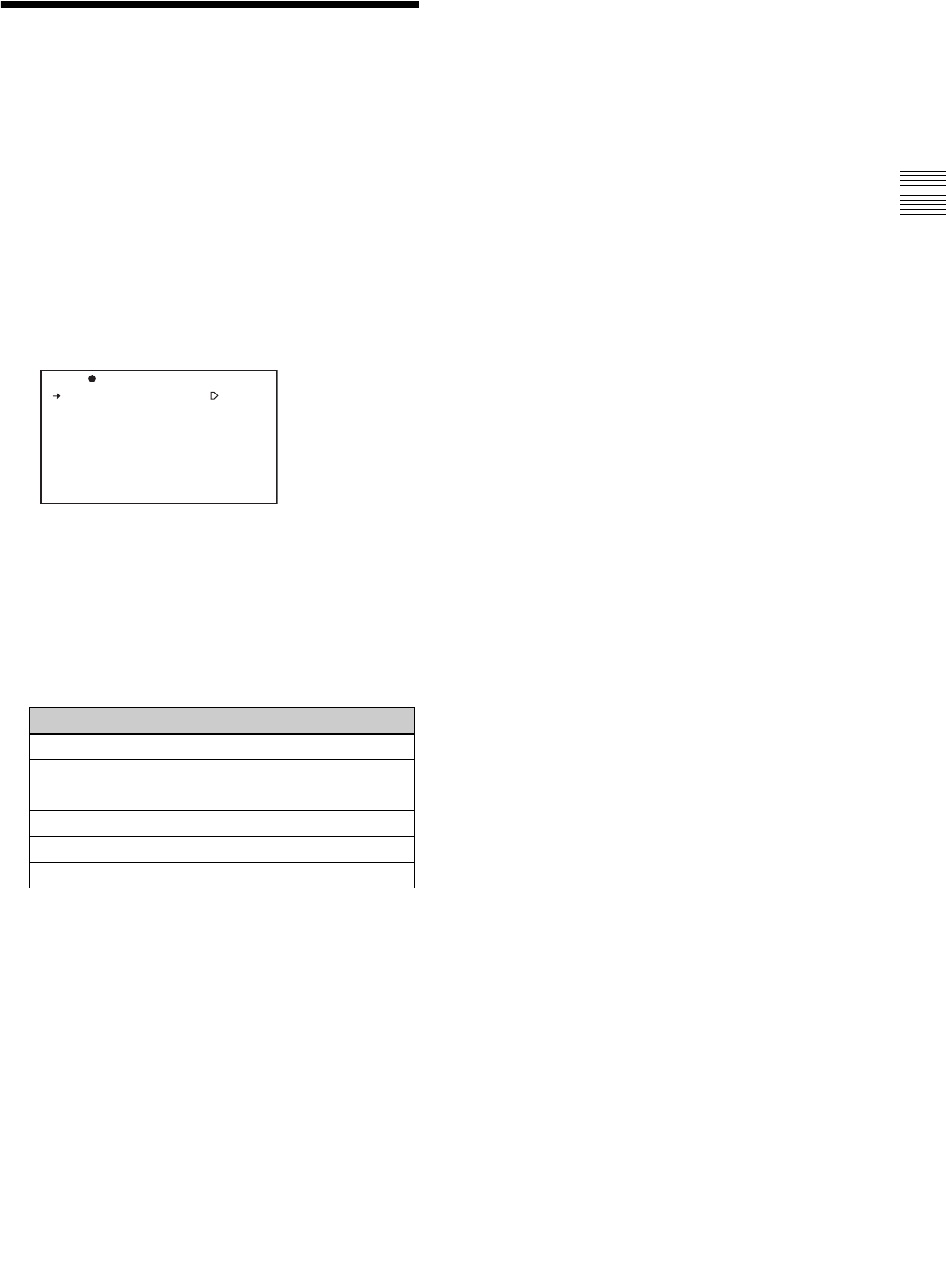
39
Setting the Date and Time of the Internal Clock
Chapter 2 Preparations
Setting the Date and Time
of the Internal Clock
You can set the date and time of the internal clock. The
date and time set here are reflected in timecode.
(How to select an item in the menu screen: Turn the
MENU knob to move the b mark to the desired item.)
1
Display the TIME/DATE page of the OPERATION
menu, and press the MENU knob.
For details on menu operations, see “Basic Menu
Operations” on page 131.
2
Select ADJUST, and press the MENU knob.
The TIME ADJUST screen appears.
3
Select a desired setting item, and press the MENU
knob.
You can set the following items in the TIME ADJUST
screen.
4
Turn the MENU knob to select the desired setting, and
press the MENU knob.
5
Repeat steps 3 and 4 until you have set all of the
desired items.
6
When you are finished making settings, select OK, and
press the MENU knob.
The internal clock is set with the date and time set in
steps 3 to 5. The TIME/DATE page of the
OPERATION menu appears again. The time set in the
TIME ADJUST screen is displayed.
To cancel the setting
Before executing step 6, select ESC and press the MENU
knob.
All the settings so far made are discarded and the TIME/
DATE page appears again.
Item Description
HOUR Sets the hour value.
MIN Sets the minutes value.
SEC Sets the seconds value.
YEAR Sets the year.
MONTH Sets the month.
DAY Sets the day.
A DJUST : EX EC
H OUR : 12
M IN : 55
S EC : 58
Y EAR : 00
M ONTH : 07
D AY : 31
TO P?0 18 TI ME /D ATE
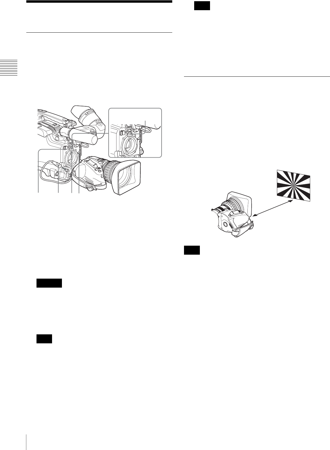
40 Preparing the Lens
Chapter 2 Preparations
Preparing the Lens
Mounting the Lens
First power off the unit, and then mount the lens using the
following procedure.
(To mount a 1/2-inch type lens, carry out steps 1 to 3.)
For information about using the lens, refer to the
operating instructions for the lens.
1
Push the lens locking lever up and remove the lens
mount cap from the lens mount.
2
Align the center pin on the lens with the center slot in
the lens mount, and insert the lens into the mount.
3
Holding the lens in place, push the lens locking lever
down to lock the lens.
If the lens is not firmly locked, it may come off while
the camcorder is being used. This could cause a serious
accident. Make sure the lens is firmly locked. It is
recommended that the lens mount securing rubber be
put on the lens locking lever as illustrated above.
Mounting a 2/3-inch type lens requires a 2/3-inch type
lens mount adaptor.
4
If a 2/3-inch type lens has been mounted, connect the
lens cable to the LENS connector.
Connecting the lens cable to the LENS connector
when the camcorder is powered may cause a
malfunction of the camcorder or the lens. Before
connecting the lens cable, be sure to check that the
camcorder is powered off.
5
Secure the lens cable with the cable clamps.
Adjusting the Flange Focal Length
If the focus is not precisely correct at the telephoto and
wide-angle ends of zoom operations, adjust the flange
focal length (the distance from the lens mounting flange
plane to the focusing plane).
Once adjusted, no further adjustment is required unless the
lens is changed.
When carrying out the adjustment, use the supplied flange
focal length adjustment chart as the subject.
If you use a subject with insufficient contrast, or move the
camera or subject during adjustment, this will cause an
adjustment error.
Carrying out the adjustment
When using the VCL-719BXS Auto Focus Lens
With the VCL-719BXS lens supplied with the PDW-
F330K, zoom and focus operations automatically adjust
the flange focal length.
Caution
Note
1
3
245
Lens mount
securing rubber
Note
Note
Flange focal length
adjustment chart (supplied)
Approx. 3 m
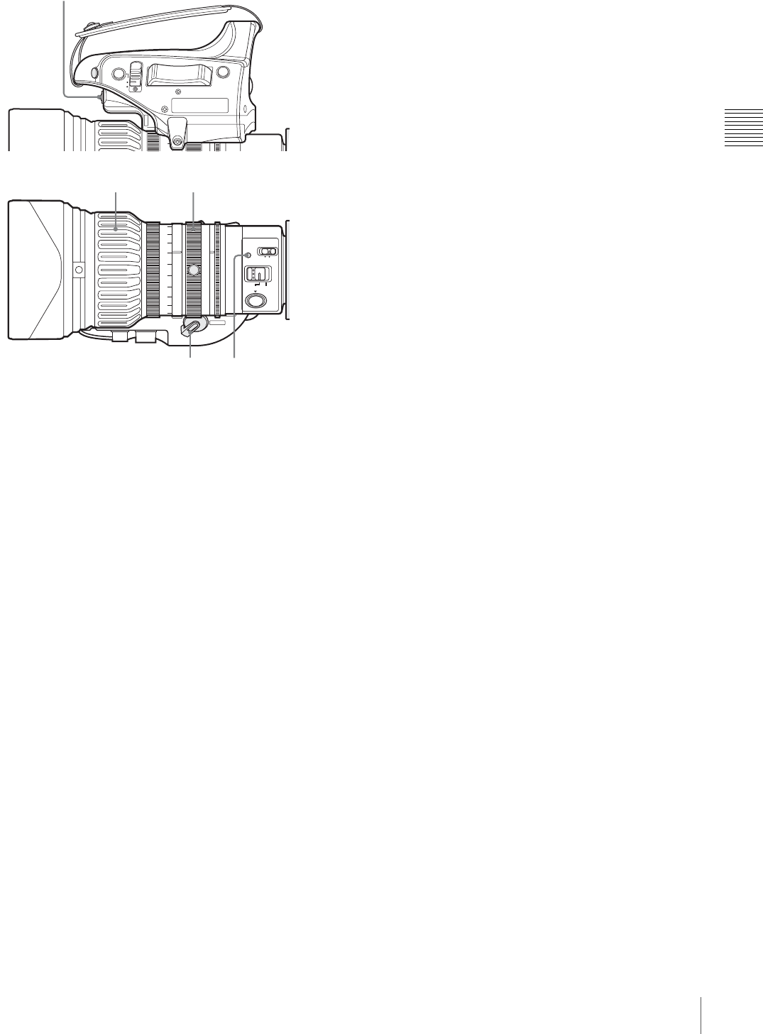
41
Preparing the Lens
Chapter 2 Preparations
1
Open the iris, position the supplied flange focal length
adjustment chart approximately 3 meters away from
the camera, and arrange the lighting to obtain a
satisfactory video output.
2
Set the ZOOM switch to SERVO (power zoom mode).
3
Hold down the flange focal length adjustment button
for 3 seconds.
The auto focus indicator flashes orange, and the flange
focal length adjustment starts.
During adjustment
The auto focus indicator flashes alternately orange and
green.
The message “AUTO FB EXECUTING” appears on
the viewfinder screen.
If the adjustment completes correctly
The auto focus indicator goes off, and the message on
the viewfinder screen changes to “FB: OK”.
If the flange focal length adjustment does not
complete correctly
The auto focus indicator lights red.
Check the subject and lighting conditions, and repeat
the adjustment.
When using a non-auto focus lens
Read the instruction manual for the lens in use as well.
1
Set the iris to manual.
2
Open the iris, position the supplied flange focal length
adjustment chart approximately 3 meters away from
the camera, and arrange the lighting to obtain a
satisfactory video output.
3
Loosen the fixing screws on the F.f or F.B ring (flange
focal length adjustment ring).
4
Use manual or power zoom to set the lens to telephoto.
5
Point the camera at the chart by turning the focus ring
and focus on the chart.
6
Set the zoom ring to wide angle.
7
Turn the F.f or F.B ring until the chart is in focus,
being careful not to disturb the focus ring.
8
Repeat steps 4 to 7 until the chart stays in focus ring.
9
Tighten the F.f or F.B ring fixing screws.
M
MACRO
A
PUSH
AF
FOCUS
ON OFF
SERVO MANU.
ZOOM
T
W
AM
RET
IRIS
Flange focal length
adjustment button
Auto focus indicator
Zoom ringFocus ring
ZOOM switch
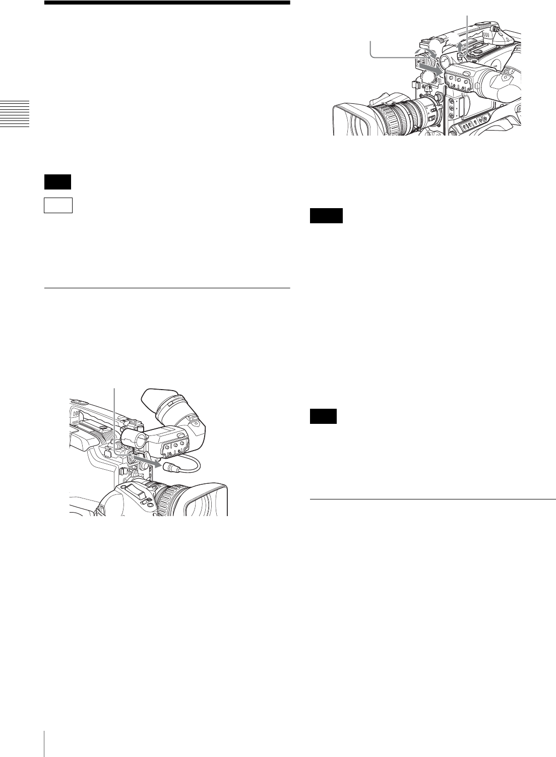
42 Adjusting the Viewfinder
Chapter 2 Preparations
Adjusting the Viewfinder
Depending on the eyesight of the operator — whether
longsighted or shortsighted — the optimal position of the
viewfinder image varies. Adjusting brightness, contrast,
and so on, improves the visibility of the viewfinder screen.
Although these adjustments may make the viewfinder
image clearer, they have no effect on the output video
signal from the camcorder.
(The description shown below uses the DXF-801/801CE
illustrations; it also applies to the DXF-20W.)
Since the fitting dimensions are different on the camera
and viewfinder, to attach a DXF-20W (not supplied) to the
PDW-F330, it is necessary to change the fitting (supplied
with the DXF-20W).
Detaching the Viewfinder
Remove any microphone from the viewfinder beforehand.
1
Power off this unit, then unplug the viewfinder
connector from the VF connector.
2
Loosen the viewfinder left-to-right positioning ring
1, and with the stopper raised 2, detach the
viewfinder 3.
To attach the viewfinder
Reverse the detaching procedure. (Note that it is not
necessary to raise the stopper.)
Note the following points when mounting the viewfinder.
• Be sure to power off this unit before plugging the
viewfinder connector into the VF connector on this unit.
If the connector is plugged in while the power is on, the
viewfinder may not operate correctly.
• Make sure that the viewfinder connector is pushed fully
into the VF connector on the unit. If the connector is not
firmly connected, the image may break up, or the tally
light may not operate properly.
Using a left eye adaptor (DXF-801 only)
By fitting a left eye adaptor, you can use the camcorder
with your left eye to the viewfinder.
You cannot stow the camcorder in the carrying case with
the left-eye adaptor attached.
For details, consult your Sony dealer.
Adjusting the Viewfinder Position
To adjust the viewfinder left-to-right position, loosen the
left-to-right positioning ring, and to adjust the front-to-
back position, loosen the front-to-back positioning knob.
Note
F330
VF connector
Notes
Note
2
3
1
Viewfinder left-to-right
positioning ring
Stopper
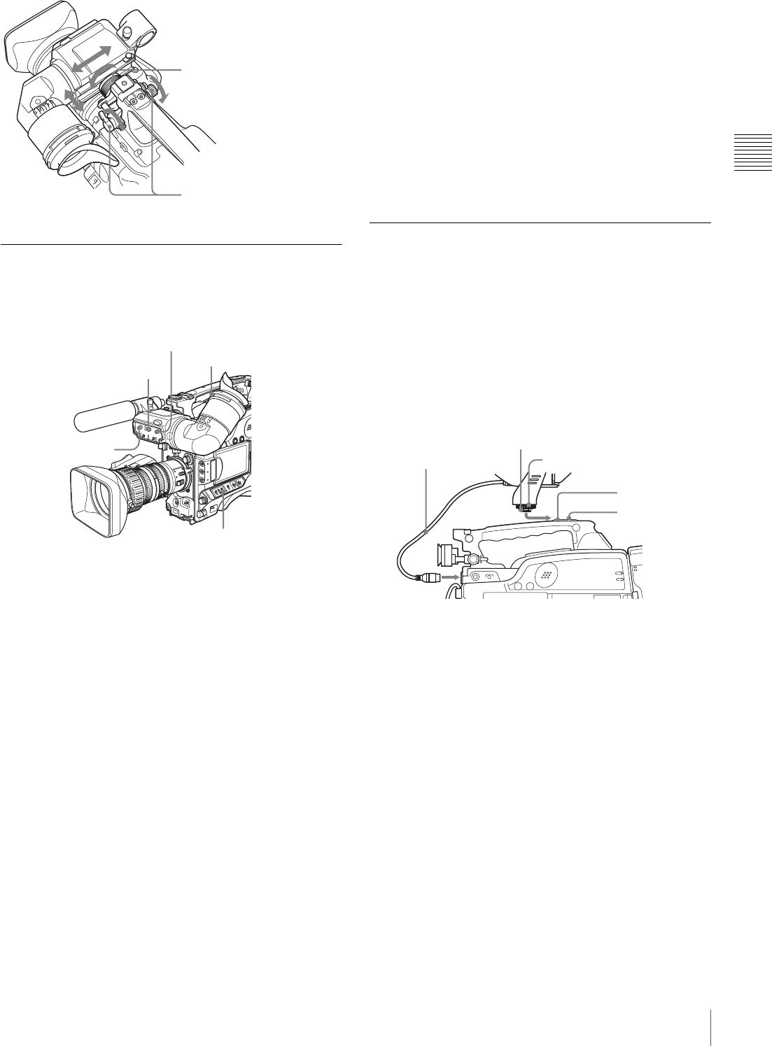
43
Adjusting the Viewfinder
Chapter 2 Preparations
Adjusting the Eyepiece Focus and
the Screen (Brightness, Contrast,
and Outline Emphasis)
a) For the DXF-20W, the eyepiece focusing ring.
To adjust the eyepiece focus
First focus the image with the lens, then adjust the
eyepiece focusing knob or eyepiece focusing ring to get
the clearest viewfinder image for your eyesight.
The visual adjustment range is –3D to 0D (DXF-801) or
–3.5D to +0.4D (DXF-20W).
You can change the adjustment range by installing an
exchange part. The adjustment range after the exchange is
as follows.
• DXF-801: –2D to +1D, or –0.5D to +3D
• DXF-20W: –3.6D to –0.8D, or –2.8D to +2.0D
Contact a Sony service representative for more
information about exchange parts.
To adjust contrast and brightness
Carry out these adjustments with the color bars displayed.
1
Set the OUTPUT/DCC switch to the BARS position.
The color bars appear on the viewfinder screen.
2
Watching the color bars, turn the CONTRAST and
BRIGHT controls to adjust the contrast and
brightness.
3
Return the OUTPUT/DCC switch to its original
position.
To adjust the outline emphasis
Turning the PEAKING control changes the degree of
outline emphasis in the viewfinder image, to make
focusing easier.
Attaching a 5-inch Electronic
Viewfinder
You can attach an optional DXF-51 (5-inch) Electronic
Viewfinder. To attach it, an Accessory Shoe Kit (service
part number: A-8274-968-B) is required.
For details, contact your Sony dealer.
Remove the cover of the grip, and attach the shoe and
stopper screw (of the Accessory Shoe Kit).
a) Supplied with the Accessory Shoe Kit
Viewfinder left-to-right
positioning ring
Viewfinder front-to-back
positioning knob
Eyepiece focusing knob a)
BRIGHT control
CONTRAST control
OUTPUT/DCC switch
PEAKING control VF Cable
Guide plate
Fixing ring
Shoe a)
Stopper screw a)
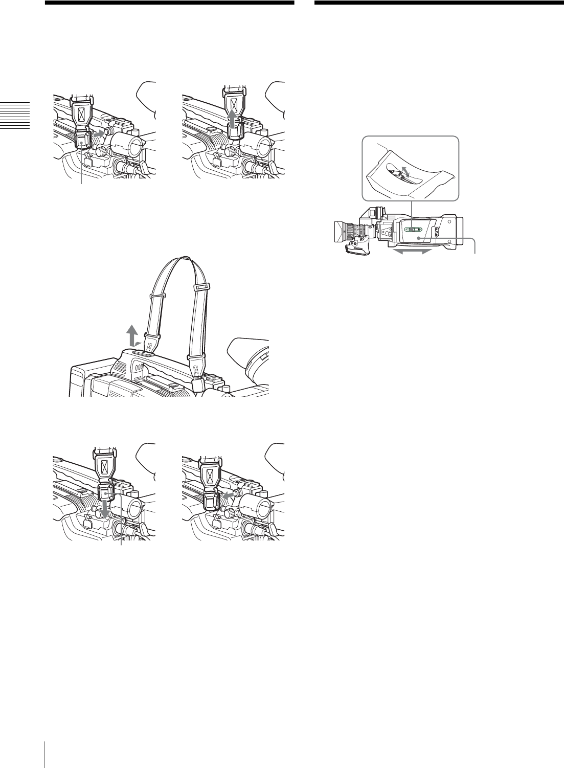
44 Using the Shoulder Strap / Adjusting the Shoulder Pad Position
Chapter 2 Preparations
Using the Shoulder Strap
1
Fit one of the clips to a shoulder strap fitting.
2
Fit the other clip to the shoulder strap fitting on the
other side of the grip in the same way as in step 1.
To remove the shoulder strap
Adjusting the Shoulder
Pad Position
You can shift the shoulder pad backward or forward by up
to 35 mm (1 7/16 inches). This adjustment helps you get the
best balance for shooting with the camcorder on your
shoulder.
1
Raise the lever in the center of the shoulder pad to
unlock the shoulder pad.
2
Slide the shoulder pad backward or forward until it is
in the most convenient position.
3
Bring down the lever to lock the shoulder pad in the
selected position.
g
Clip Pull up the strap to lock
the fitting.
g
Pull in the direction of the arrow
while pressing here.
1,3
2
Bottom of the
camcorder
Shoulder pad
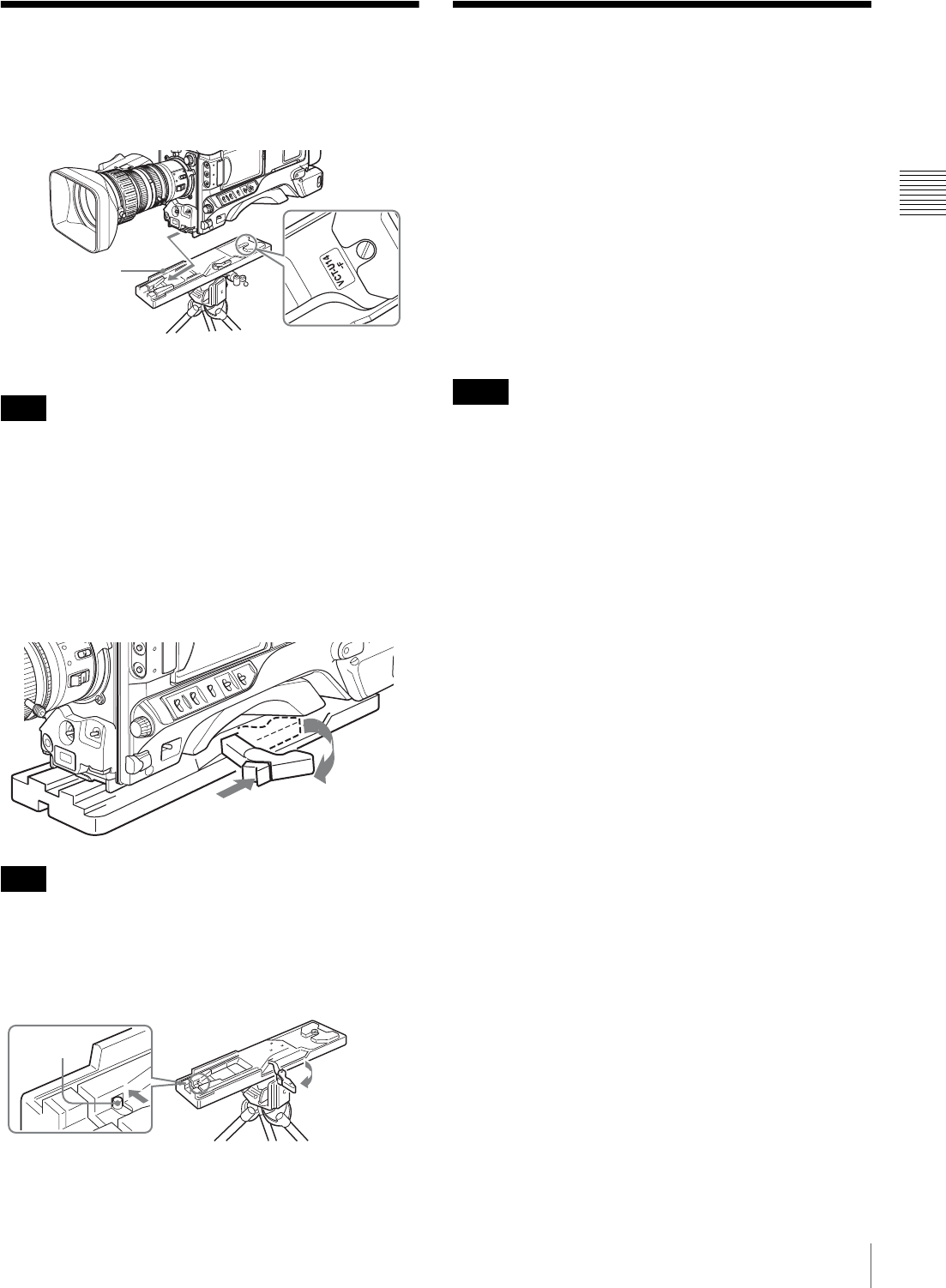
45
Mounting on a Tripod / Using a Video Light
Chapter 2 Preparations
Mounting on a Tripod
First fit the VCT-U14 Tripod Adaptor to the tripod, then
mount the camcorder on the tripod adaptor.
The camcorder cannot be mounted on a tripod adaptor with
one of the following indications in the model name space,
as shown in the above illustration. Use the appropriate
tripod adaptor.
• “VCT-U14” only
• “VCT-U14-B”
• “VCT-U14-D”
To remove the tripod
After removing the camcorder, if the tripod adaptor pin has
not returned to its original position, hold down the red
button and move the lever in the direction of the arrow to
return the pin to its original position. It is not possible to
mount a camcorder with the pin left out.
Using a Video Light
With this camcorder, you can use the Anton Bauer
Ultralight 2 or equivalent video light (powered by 12 V
with maximum power consumption of 50 W).
• If you connect the video light to the LIGHT connector on
the camcorder and set the LIGHT switch to AUTO, you
can turn the light on and off automatically as you start
and stop the VDR operation.
• The output of the video light connector on the camcorder
is controlled to 12 V even when the camcorder is
supplied with 12 V or more power (through the DC IN
connector or battery pack). The brightness or color
temperature of the light will not change according to
voltage increase.
• Do not use a video light with power consumption of over
50 W.
• The brightness or color temperature of the light will
change when the voltage (supplied through the DC IN
connector or from the battery pack) is under 12 V.
To attach the video light
Fit the video light to the accessory fitting shoe on the
camcorder grip, and connect the video light cable to the
LIGHT connector.
The accessory fitting shoe on this unit is of the 1/4-inch
tapped hole type. If you want to replace this with a slide-
type shoe, contact your Sony dealer.
Note
Note
Slide the camcorder forward along the
slot, until it clicks firmly into place.
VCT-U14 Tripod
Adaptor Tripod
Model name space
Hold down the red button and pull the
lever in the direction of the arrow.
Pin
Notes
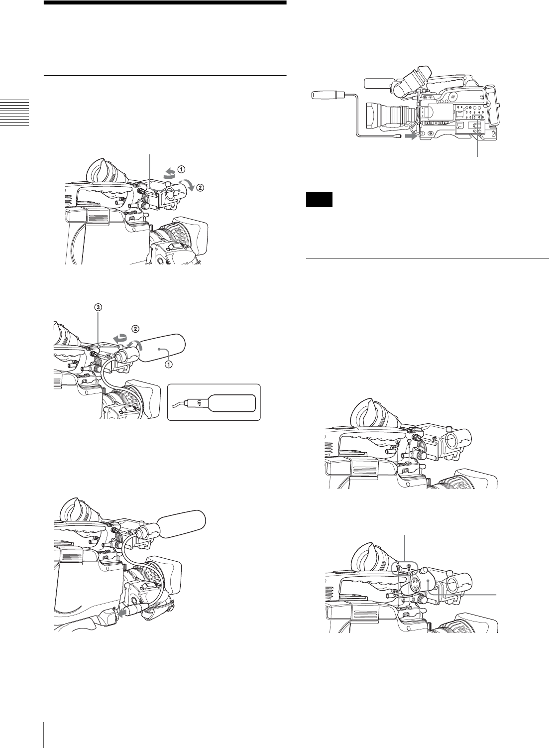
46 Preparing the Audio Input System
Chapter 2 Preparations
Preparing the Audio Input
System
Using the Supplied Microphone
1
Loosen the screw and open the microphone holder
clamp.
2
Place the microphone in the microphone holder.
3
Plug the microphone cable into the MIC IN connector,
then set the AUDIO IN switch for the channel on
which you want to record the audio from this
microphone to FRONT (or F).
To use the microphone detached from the
camcorder
You can use the supplied microphone detached from the
camcorder.
When using the supplied microphone with an extension
cable, always use an external power supply type cable.
Using an External Microphone
You can connect up to two external monaural microphones
to the AUDIO IN CH-1/CH-2 connectors, using a CAC-12
Microphone Holder (not supplied).
The following is the procedure for attaching an electret
condenser microphone such as the ECM-673/674/678.
1
Remove the fixing screws for external microphone
holder.
2
Attach the CAC-12 Microphone Holder.
3
Open the CAC-12 and remove the microphone
adaptor.
Clamp of the microphone holder
Place the microphone in the
holder so that “UP” is at the top
Tighten the screw.
Close the microphone holder.
Connect to the MIC IN connector.
Note
Set the AUDIO IN switch for the channel on which you
want to record the audio to FRONT (or F).
Connect to the MIC IN connector.
CAC-12
S
crews removed in step 1
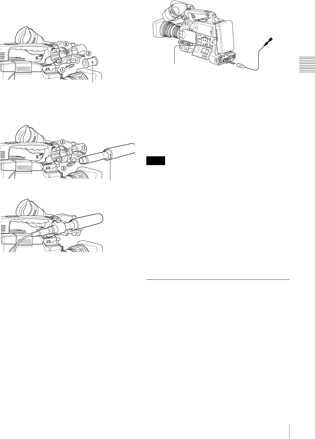
47
Preparing the Audio Input System
Chapter 2 Preparations
When attaching an ECM-673/674/678, use the
microphone adaptor supplied with the ECM-673/674/
678.
4
Place an external microphone (electret condenser
microphone such as the ECM-673/674/678) in the
CAC-12.
5
Connect the microphone cable to the AUDIO IN CH-
1 or CH-2 connector.
6
Set the switches as follows.
• Set the AUDIO IN input selection switch as
indicated below, depending on the type of
microphone used.
-When using a microphone with an internal
power supply, set it to MIC (center).
-When using a microphone with an external
power supply, set it to MIC +48V ON (right).
• Set the AUDIO IN (CH-1/CH-2/CH-3/CH-4) switch
for the channel to which the microphone is
connected to REAR (or R).
7
Switch the input level to match the sensitivity of the
microphone used.
Switch the input level by changing the REAR MIC
REF setting on the AUDIO-1 page of the
MAINTENANCE menu (factory default setting is –60
dB).
For more details, see page 122.
• If the input level on this unit is not at an appropriate
setting for the microphone sensitivity, loud sounds may
be distorted, and the signal-to-noise ratio may be
affected.
• In order for the AUDIO IN CH-1 and CH-2 connectors
on the camcorder to be able to provide a phantom 48 V
power supply, female XLR connectors (3-pin) are fitted.
If the microphone cable has a female connector, use an
adaptor.
• When you detach a CAC-12 Microphone Holder once
you have attached to the camcorder, be careful not to
lose the two screws fixing the CAC-12. After detaching
the CAC-12, be sure to put the two screws back into their
original places.
Attaching a UHF Synthesized Tuner
You can record sound by using a wireless microphone
system consisting of the following.
• WRT-804/807S UHF Wireless Microphone
• WRT-822/824 UHF Synthesized Transmitter
• WRR-855/861/862 UHF Synthesized Tuner
For details on using the wireless microphone system, see
the operating instructions for the microphone and tuner.
To attach a WRR-855
1
Open the cover of the WRR connector.
Microphone adaptor
Open the CAC-12.
Loosen the screw.
ECM-673/674/678 or
similar microphone
Close the CAC-12.
Tighten the screw.
m
Notes
to AUDIO IN CH-1/CH-2
connector
Monaural microphone
AUDIO IN (CH-1/CH-2)
switches
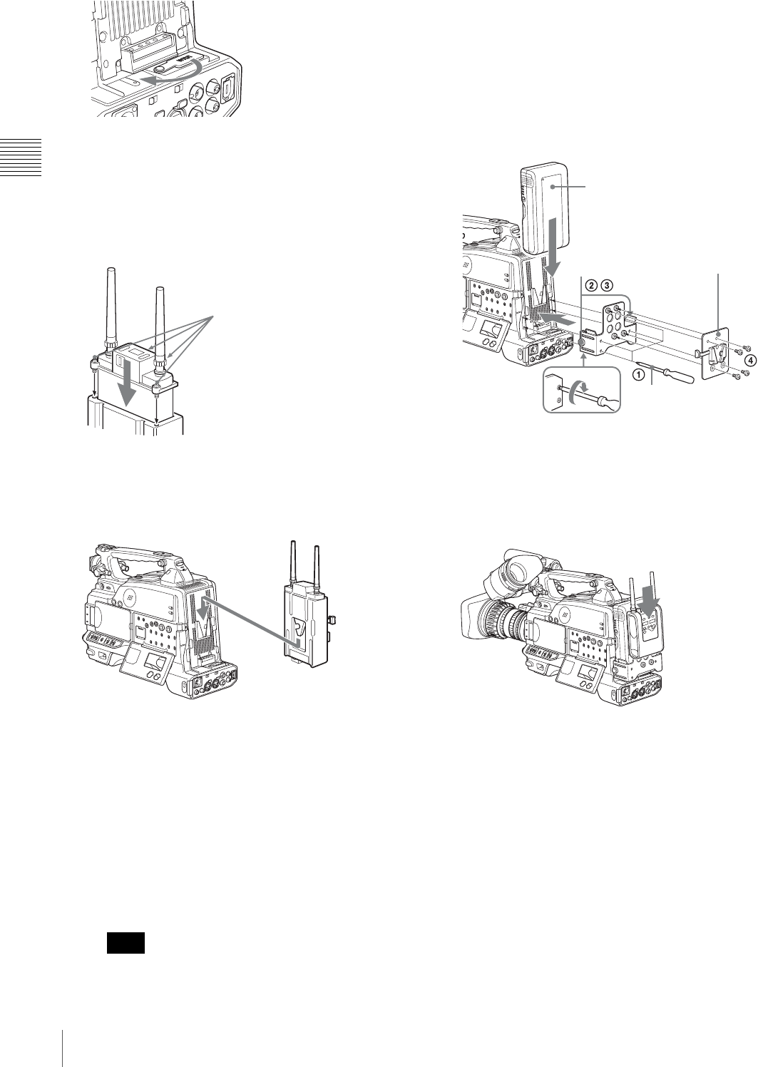
48 Preparing the Audio Input System
Chapter 2 Preparations
2
Set the power switch of the WRR-855 to ON, and set
MUTING to ON or OFF.
This enables the WRR-855 power to be turned on and
off with the camcorder POWER switch.
3
Insert the WRR-855 into the CA-WR855.
4
Engage the V-shaped plate on the back of the
CA-WR855 with the V-groove on the battery
attachment shoe, and then slide the CA-WR855 down
until it connects to the WRR connector.
5
Set the AUDIO IN switch to WIRELESS (or W).
To attach a WRR-861/862 (When using a
BP-GL95/GL65/L60S/L80S Battery Pack)
1
Attach a WRR tuner fitting (not supplied, service part
number: A-8278-057-B) to the back of the camcorder.
1 Use a Phillips type screwdriver to tighten the four
screws placed in the tuner fitting as illustrated
below.
Check that the four screws are firmly tightened.
2 Loosen the adjustment screws of the tuner fitting.
3 Adjust the tuner fitting position for a BP-GL95/
GL65/L60S/L80S Battery Pack to be attached, and
tighten the adjustment screws to fix its position.
4 Attach the mount plate supplied with the WRR-
861/862.
2
Attach the battery pack.
For details about attaching the battery pack, see
“Using a Battery Pack” on page 36.
3
Mount the tuner on the WRR tuner fitting.
For details about the WRR tuner fitting (service part
number: A-8278-057-B), contact your Sony dealer.
4
Connect the tuner power cord to the DC OUT
connector of the camcorder, and the audio output cable
to the AUDIO IN CH-1 or CH-2 connector.
5
Set the switches as follows.
• Set the AUDIO IN input selection switch to MIC for
the channel to which the audio output cable is
connected.
• Set the AUDIO IN (CH-1/CH-2/CH-3/CH-4) switch
for the channel to which the audio output cable is
connected to REAR (or R).
Note
WRR connector
Fasten the screws
(supplied with the WRR-855).
CA-WR855
Phillips type screwdriver
BP-GL95/GL65/L60S/L80S
Back of the
camcorder
Mount plate (supplied
with WRR-861/862)
Adjustment
screws
WRR-861/862
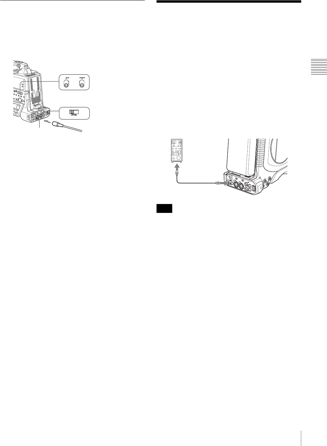
49
Connecting the Remote Control Unit
Chapter 2 Preparations
Connecting Line Input Audio
Equipment
1
Connect an audio mixer or other external audio system
component to the AUDIO IN CH-1/CH-2 connector as
shown below.
2
Set the AUDIO IN input selection switch to LINE for
the channel to which the external audio equipment is
connected.
Selection of the recording audio input
Set the AUDIO IN (CH-1/CH-2/CH-3/CH-4) switch for
the channel to which the audio device is connected to
REAR (or R).
Connecting the Remote
Control Unit
Connecting the RM-B150/B750 Remote Control Unit
enables remote control of the principal camera and VDR
functions.
Connecting the remote control unit to the REMOTE
connector (8-pin) automatically puts the camcorder into
remote control mode. If you disconnect the remote control
unit, the remote control mode is cancelled.
Refer to the RM-B150/B750 Operation Manual for the
maximum cable length for connections between the
camcorder and the RM-B150/B750.
Before connecting/disconnecting the remote control unit
to/from the camcorder, be sure to turn off the camcorder
POWER switch.
Camcorder switch functions when the
remote control unit is connected
Connecting the remote control unit disables the following
switches on the camcorder.
• GAIN switch
• OUTPUT/DCC switch
• WHITE BAL switch
• AUTO W/B BAL switch
• SHUTTER switch
Paint adjustment when the remote control
unit is connected
The settings of the paint adjustment that were in effect the
last time the remote control unit was used are recalled.
When the monitor is connected to the
remote control unit
The MONITOR connector (BNC type) of the RM-B150/
B750 outputs the same signal as that from the VIDEO
OUT connector on the camcorder.
LINE MIC
+48V ON
FRONT
WIRELESS
REAR
AUDIO IN
to audio mixer, etc.
AUDIO IN (CH-1/CH-2) switch:
Set to REAR.
AUDIO IN CH-1/CH-2
connector
AUDIO IN input selection switch:
Set to LINE.
Note
RM-B150/B750
REMOTE
connector
Remote control cable

50 Connecting the Remote Control Unit
Chapter 2 Preparations
Use the black cable supplied with the RM-B150/B750 to
connect the monitor to the MONITOR connector on the
RM-B150/B750.
When the remote control unit is
disconnected from the camcorder
The camcorder settings return to the settings in effect
before the remote control unit was connected.
Structure of the paint adjustment data
The non-volatile memory of the camcorder used for
storing paint adjustment data consists of two regions as
shown below: one is the “independent data region” that is
used when a remote control unit is not connected, and the
other is the “remote control data region” that is used when
a remote control unit is connected. Paint adjustment data is
automatically selected and output to the camera section
depending on whether or not a remote control unit such as
the RM-B150 is connected.
Thus, when a remote control unit is connected to the
camcorder, the effective data region is switched to the
“remote control data region” and the settings of the paint
adjustment that were in effect the last time the remote
control unit was used are recalled.
The settings of the absolute value rotational controls 1) and
absolute value switches 2) are overwritten by those on the
remote control unit after the remote control unit is
connected.
When the remote control unit is disconnected from the
camcorder, the “independent data region” becomes
effective. Thus the camcorder will return to the settings
that were in effect before the remote control unit was
connected.
1) Absolute value rotational controls: The data corresponding to the
angular position of controls is output. Rotational controls for which the
data corresponding to the amount of their rotation is output are called
relative value controls.
2) Absolute value switches: Like toggle switches or slide switches (except
momentary switches), the switches (or knobs) whose positions must
coincide with their functions are called absolute value switches.
Non-volatile memory
Independent data
region
MASTER BLACK
MASTER GAMMA
KNEE POINT
DETAIL LEVEL
R/B GAIN
R/B BLACK
Remote control
data region
MASTER BLACK
MASTER GAMMA
KNEE POINT
DETAIL LEVEL
R/B GAIN
R/B BLACK
Setup
menu of
the
camcorder
RM-B150
Hardware
of the
camera
section
RM-B150 connected
RM-B150 not
connected
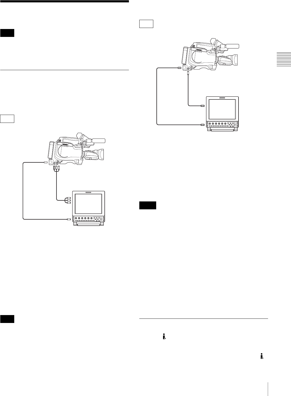
51
Connecting
Chapter 2 Preparations
Connecting
Some of the peripheral devices and related products
referred to in this section may be no longer in production.
When selecting the devices, consult your Sony dealer.
Connecting an External Video
Monitor
When using a Sony liquid crystal display monitor, make
the connections as follows.
aTo check an analog HD/SD (NTSC/PAL) signal
Connect the VIDEO OUT Y/PB/PR connectors of this unit
and the RGB/COMPONENT input connectors of the
LMD-9030 liquid crystal display monitor with a
component video cable (not supplied).
The signal output from the VIDEO OUT Y/PB/PR
connectors can be switched with “COMPONENT OUT”
on the OUTPUT page of the OPERATION menu. For more
details, see page 114.
It is not possible to add text information or markers to the
HD output.
bTo check an SD (NTSC/PAL) signal
Connect the VIDEO OUT connector of this unit and the
LINE A or LINE B input connector of the LMD-9030
liquid crystal display monitor with a 75" coaxial cable
(not supplied).
aTo check an HDSDI signal
Connect the HDSDI OUT connector of this unit and the
SDI input connector of the LMD-9050 liquid crystal
display monitor with a 75" coaxial cable (not supplied).
Note that regardless of the recording format (MPEG HD/
DVCAM), during recording or while recording is stopped
an HD signal is output.
• When playing back video recorded in SD format
(DVCAM format), no signal is output from the HDSDI
OUT connector.
• Text information and markers cannot be superimposed
on the HDSDI output.
bTo check an SD (NTSC/PAL) signal
Connect the VIDEO OUT connector of this unit and the
LINE A or LINE B input connector of the LMD-9050
liquid crystal display monitor with a 75" coaxial cable
(not supplied).
The items displayed on a monitor are same as the ones on
the viewfinder screen. For details, see “Status Display on
the Viewfinder Screen” on page 31.
Using an i.LINK Connection
Using the (i.LINK) DV OUT S400 connector, you can
connect external equipment to the camcorder.
Video recorded in the MPEG HD format is down-
converted to the DVCAM format and output from the
(i.LINK) DV OUT S400 connector.
Note
F330
Note
275" coaxial
cable
PDW-F330
LMD-9030 liquid crystal
display monitor
to VIDEO OUT Y/PB/PR connector
to LINE A/B input connector
to VIDEO OUT
connector
to RGB/COMPONENT
input connector
1 Component video cable
F350
Notes
175" coaxial
cable
PDW-F350
LMD-9050
liquid crystal display monitor
to VIDEO OUT connector
to SDI input connector
to HDSDI OUT
connector
to LINE A/B input
connector
275" coaxial cable
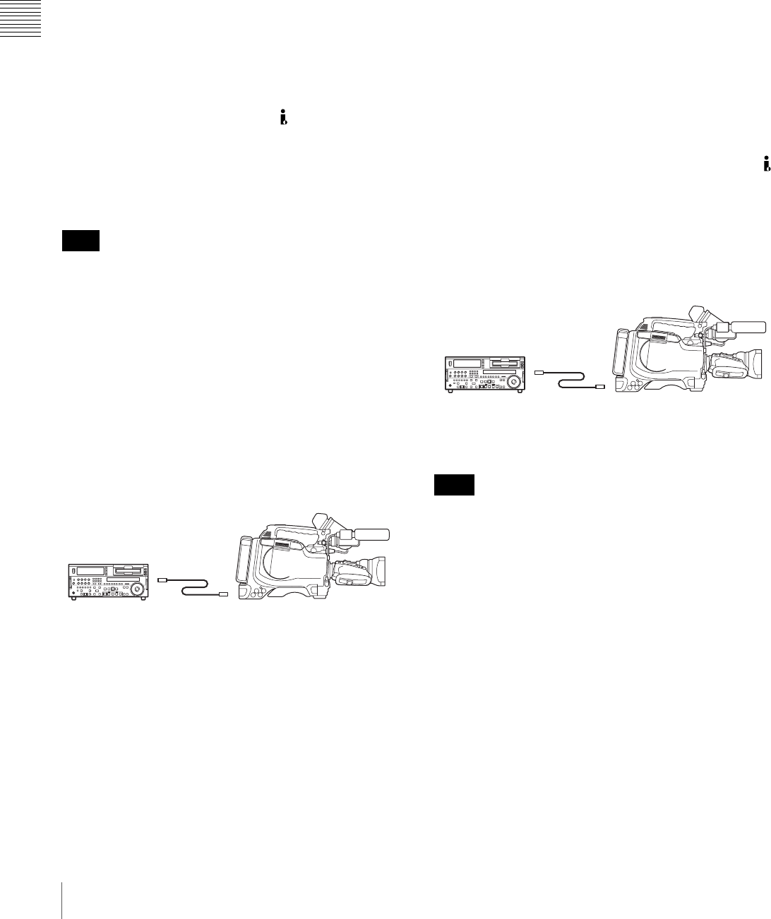
52 Connecting
Chapter 2 Preparations
For connections using FAM (file access mode), see “File
Operation” (page 155).
Settings required for an i.LINK connection
i.LINK MODE setting
Set the method of connection between this unit and an
external device. On the OUTPUT page of the
OPERATION menum, set i.LINK MODE to AV/C
(Audio/Video Control). (The factory default setting is AV/
C.)
Make the i.LINK AUDIO OUT setting depending on the
connected device (see the next item).
i.LINK AUDIO OUT setting
Set the audio output channels for the (i.LINK) DV OUT
S400 connector. On the AUDIO-2 page of the
MAINTENANCE menu, set i.LINK AUDIO OUT to one
of the following. (The factory default setting is “2CH”.)
2CH: Output channels 1 and 2 (16 bits, 48 ksps)
4CH: Output channels 1 to 4 (12 bits, 32 ksps)
When the scan mode is 23.98P, video, audio, or timecode
output via the i.LINK connection may not be continuous.
Using the camcorder as a feeder
To copy digitally from the camcorder to the VTR
without the editing function
Using an i.LINK cable (DV cable) to connect a digital
video cassette recorder with an i.LINK connector to the
camcorder, digital copy of video and audio can be carried
out.
Example of connection
1
Make the following settings to prepare the external
VTR.
• Set REC MODE to the same recording mode as that
of the camcorder.
• In NTSC color system, when the recording mode is
set to DVCAM, select either DF or NDF.
• Set AUDIO MODE to either 4-channel or 2-channel
mode, according to the disc that is played on the
camcorder.
2
Pause recording on the external VTR.
3
Play the disc on the camcorder.
4
Check the playback on the camcorder, and when
playback reaches the scene that you want to record,
start recording again on the external VTR.
The copy to the external VTR starts.
5
When copy to the external VTR is finished, stop
playback of the disc on the camcorder.
For details about external VTR operations, see the
instruction manual supplied with the external VTR.
To control the camcorder from a VTR with editing
function
By connecting a VTR with an i.LINK connector to the
(i.LINK) DV OUT S400 connector of the camcorder using
an i.LINK cable (DV cable), you can control playback and
recording on the camcorder and perform cut editing and
digital copy.
Example of connection
When using the DSR-2000A/2000AP, press the i.LINK
button on the remote control setting section of the VTR.
To use the automatic copying function of the DSR-2000A/
2000AP, it is necessary to set the recording format of the
camcorder to DVCAM on the FORMAT page of the
OPERATION menu.
For details on the external VTR, see the instruction manual
supplied with the external VTR.
To control the camcorder from a nonlinear
editing system
Using the i.LINK cable (DV cable), you can transfer video
and audio signals to a nonlinear editing system from the
camcorder. Editing software that supports the selected
recording format (DVCAM) must be used.
Note
External VTR
DSR-1800A/1800AP/
45/45P, etc.
PDW-F330/F330P/F350/F350P
i.LINK cable
(DV cable)
Note
External VTR
PDW-F330/F330P/F350/F350P
DSR-2000A/2000AP, etc.
i.LINK cable
(DV cable)
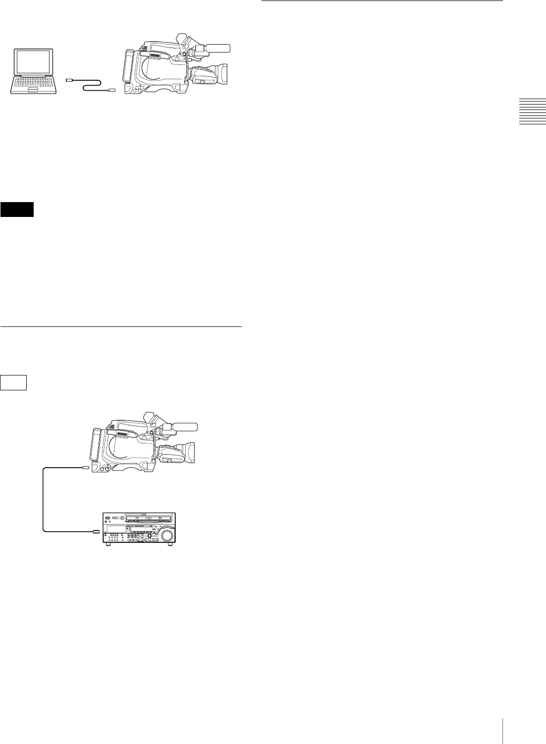
53
Connecting
Chapter 2 Preparations
Example of connection
Operate the computer to set up the nonlinear editing
software.
For details, see the software’s manual.
• Video edited using a nonlinear editing system cannot be
recorded to disc on this camcorder via an i.LINK cable
(DV cable).
• When a disc with non-continuous timecode recorded is
subjected to video capturing on a nonlinear editing
system, the capturing precision may not be frame
accurate.
Connecting Using the HDSDI
Connector
By connecting the HDSDI OUT connector of this unit and
the HDSDI input connector of the HDCAM VTR with a
75" coaxial cable (not supplied), you can carry out digital
copy.
Connections for Using the PDZ-1
To use the supplied PDZ-1 Proxy Browsing Software,
connect the computer on which PDZ-1 is installed to this
unit in FAM (file access mode).
For details of the connection, see “Making FAM
connections” on page 158.
For details of PDZ-1, see “Using the PDZ-1 Proxy
Browsing Software” on page 102.
Notes
F350
A computer in which
editing software
supporting the DVCAM
format is installed
PDW-F330/F330P/F350/F350P
i.LINK cable
(DV cable)
Laptop computer
75" coaxial
cable
PDW-F350
HDCAM VTR
(HDW-2000 or similar)
to HDSDI input connector
to HDSDI OUT
connector
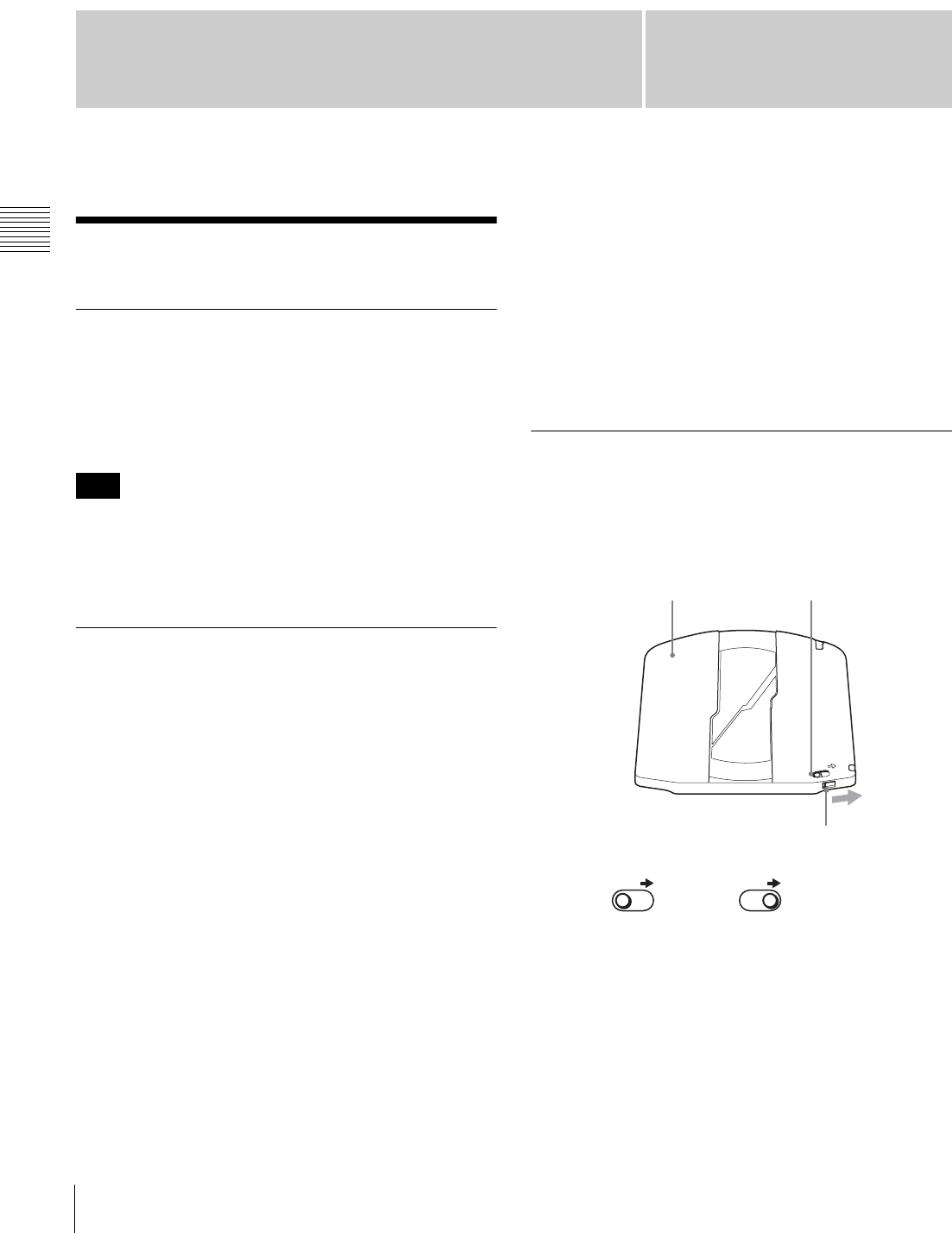
Chapter3
54 Handling Discs
Chapter 3 Recording and Playback
Recording and Playback
Handling Discs
Discs Used for Recording and
Playback
This camcorder uses the following disc for recording and
playback:
PFD23 Professional Disc (capacity 23.3 GB)
It is not possible to use the following discs for recording or
playback:
• Blu-ray Disc
• Professional Disc for Data
Notes on Handling
Handling
The Professional Disc is housed in a cartridge, and is
designed to allow handling free of risk from dust or
fingerprints. However, if the cartridge is subjected to a
severe shock, for example by dropping it, this can result in
damage or scratching of the disc. If the disc is scratched, it
may be impossible to record video/audio, or to play back
the content recorded on the disc. The discs should be
handled and stored carefully.
• Do not touch the surface of the disc itself within the
cartridge.
• Deliberately opening the shutter may cause damage.
• Do not disassemble the cartridge.
• The supplied adhesive labels are recommended for
indexing discs. Apply the label in the correct position.
Storage
• Do not store discs where they may be subjected to direct
sunlight, or in other places where the temperature or
humidity is high.
• Do not leave cartridges where dust may be able to gain
ingress.
• Store cartridges in their cases.
Care of the discs
• Remove dust and dirt on the outside of a cartridge using
a soft dry cloth.
• If condensation forms, allow ample time to dry before
use.
Write-Protecting Discs
To protect the content recorded on the disc from accidental
erasure, move the Write Inhibit tab on the lower surface of
the disc in the direction of the arrow, as shown in the
following figure.
You can also write protect individual clips. For details, see
“Locking (Write-protecting) Clips” (page 87).
Note
SAVE
SAVE SAVE
Lower surface of the disc Write Inhibit tab
Slide in the direction
of the arrow
Write Inhibit tab settings
Recording enabled Recording disabled
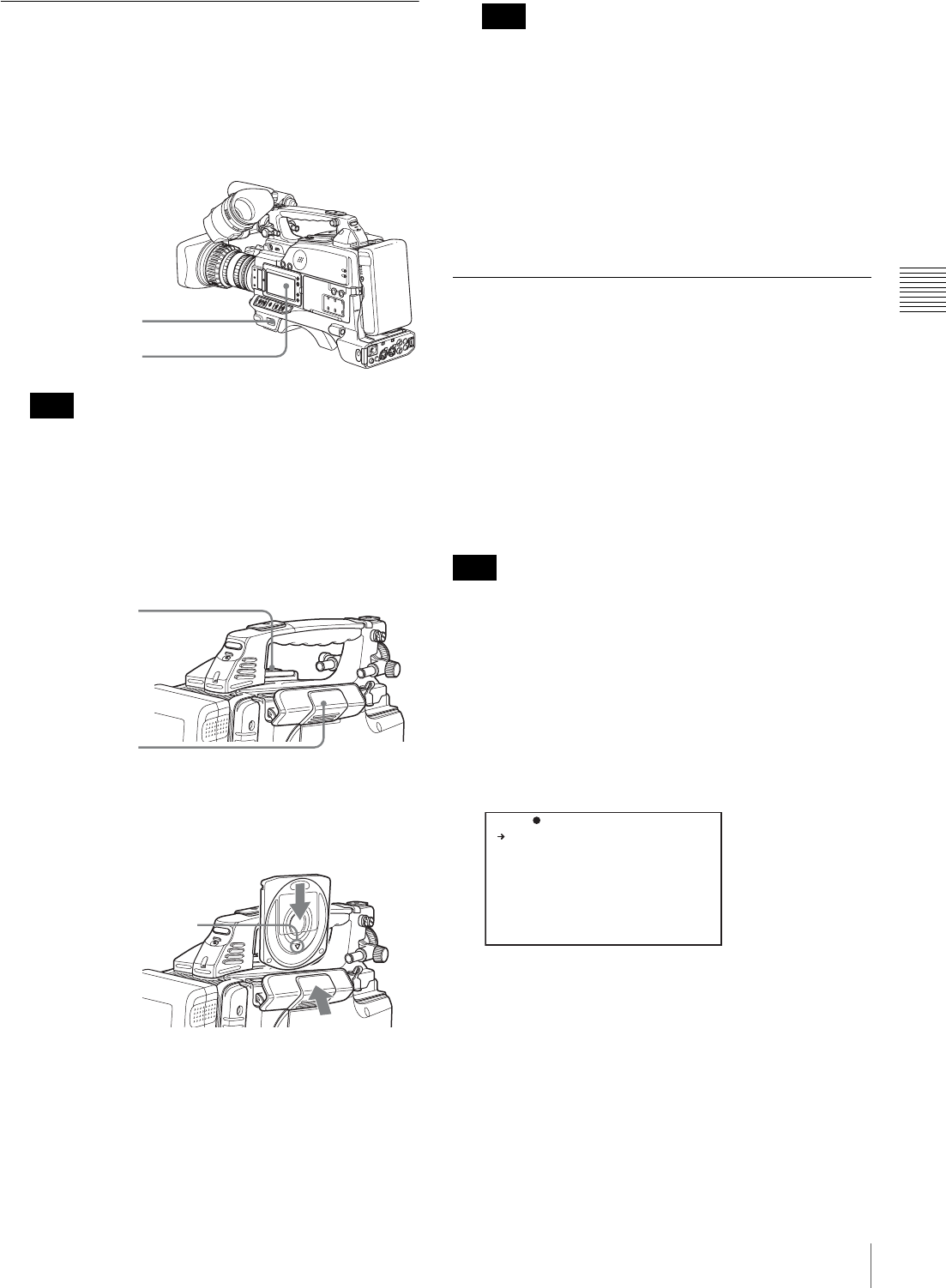
55
Handling Discs
Chapter 3 Recording and Playback
Loading and Unloading a Disc
Loading a disc
Proceed as follows.
1
Turn on the POWER switch.
If there is condensation inside the VDR section, the
message “HUMID” appears in the status display on
the LCD monitor. If this happens, wait until the
indicator goes off before going on to step 2.
2
Press the EJECT button.
This opens the lid of the disc compartment.
3
Insert the disc in the V direction, and close the disc
compartment lid manually.
The disc is loaded.
To insert the disc correctly, make sure that the
camcorder is in the upright position (the grip upside,
the bottom downside).
Unloading a disc
With the power supply on, press the EJECT button to open
the disc compartment lid and eject the disc, then remove
the disc. If you are not going to insert another disc, close
the disc compartment lid.
Formatting a Disc
Using a new disc
An unused disc requires no formatting operation. The disc
is automatically formatted so that it is ready to use when
loaded into this unit.
Using a disc on which material is recorded
To format a recorded disc, load the disc into the unit then
do as follows.
When a recorded disc is formatted, all the data on the disc
is erased. (Locked clips (see page 87) are also erased.)
(How to select an item in the menu screen: Turn the
MENU knob to move the b mark to the desired item.)
1
Display the DISC page of the USER
(or OPERATION) menu, and press the MENU knob.
For details of menu operations, see page 131.
2
Select QUICK FORMAT, and press the MENU knob.
The message “EXECUTE OK? YES b NO” appears.
3
To carry out the formatting, select YES, and press the
MENU knob.
To cancel, press the MENU knob leaving NO selected.
When formatting is completed, the message
“COMPLETED” appears.
Note
POWER switch
HUMID indicator
EJECT button
Lid of the disc
compartment
Insert the disc.
V indication on the outside
Push and close the lid.
Note
Note
D ELETE L AS T CLI P: EX EC
D ELETE A LL CLIP S: EX EC
Q UICK FO RM AT : EX EC
TO P 0 04 DI SC

56 Handling Discs
Chapter 3 Recording and Playback
Handling of Discs When Recording
Does Not End Normally (Salvage
Function)
Recording processing does not end normally if, for
example, the battery pack is removed during recording, or
if the power cord is disconnected during recording.
Because the file system is not updated, video and audio
data recorded in real time is not recognized as files and clip
contents recorded up to that point are lost.
However, this unit has a salvage function which can hold
losses to the minimum by reconstructing clips on such
discs.
Note that no recorded clip contents are lost when the
POWER switch is set to OFF and when battery exhaustion
is detected, because the unit does not become powered off
until after the end of recording processing.
• Do not disconnect the battery pack or power cord until
recording processing has finished and the ACCESS
indicator has gone out.
• This function salvages as much recorded material as
possible after an unforeseen accident, but 100%
restoration cannot be guaranteed.
• Even when this function is used, it is not possible to
recover data from immediately before the interruption of
recording. The amount of data lost is as follows.
Quick salvage: From 2 to 4 seconds of data before the
interruption of recording.
Full salvage: From 4 to 6 seconds of data before the
interruption of recording.
• More data may be lost when functions such as Interval
Rec are being used.
Quick salvage
When the unit is powered on again after a recording
interruption due to a power interruption, with the disc still
loaded in the unit, clips are reconstructed on the basis of
backup data stored in nonvolatile memory and markers
recorded on the disc. Processing time is about 5 seconds.
Full salvage
When recording on an XDCAM device is interrupted
because of a power interruption, and a disc is manually
ejected from that device with the power off, clips are
reconstructed on the basis of markers recorded on the disc
when the disc is loaded in this unit. Therefore, processing
takes longer than for a quick salvage (about 30 seconds,
although it depends on the state of the disc).
Proceed as follows to perform a full salvage.
1
Insert the disc on which recording did not end
normally.
The following salvage message appears.
2
Select YES, and press the MENU knob.
Salvage processing starts, and the message
“EXECUTING.” appears.
A results message appears when the processing
finishes.
• If the salvage succeeded, the message
“COMPLETED.” appears.
• If the salvage failed, the message
“INCOMPLETED.” appears. Clips for which
recording did not end normally are lost.
To exit without salvaging
Select NO in step 2 to exit without performing salvage
processing.
However, the status of the disc does not change.
Salvage is still required to recover the clips for which
recording did not end normally. The salvage message
will appear again when that disc is inserted again, or
when the camcorder is powered on again.
If salvage processing is not done, sections which were
recorded normally can be played back, but no new
recording can be done on the disc.
Notes
Note
TO R EC ORD O N TH E
DISC, I T IS NE CE SS AR Y
TO E XE CU TE SA LV AG E.
S AL VA GE OK ?
Y ES NO
S AL VAGE
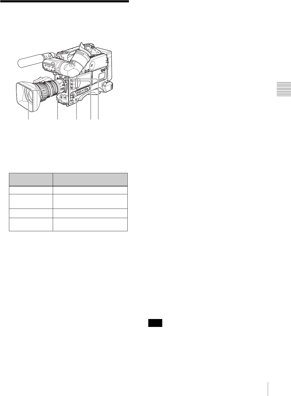
57
Basic Procedure for Shooting
Chapter 3 Recording and Playback
Basic Procedure for
Shooting
1
Set the POWER switch to ON.
2
Set the FILTER selector and the 5600K button
appropriately for the lighting conditions.
a) The range over which the subject is sharply in focus. Thus, “reducing
the depth of field” means that the range is reduced as well, and
“increasing the depth of field” means that it is increasing as well.
3
Check the switch settings on the camcorder.
If you do not have enough time to check the settings of
the unit, you can turn the EZ MODE-assigned switch
on to use EZ mode for instant shooting.
EZ mode
In EZ mode, the settings of this unit are fixed at
standard values, and the lens aperture and white
balance are adjusted automatically. In this state, it is
not possible to change menu or other settings. To
change settings, turn EZ mode off. In the factory
default configuration, the ASSIGN 1 switch (see page
142) turns EZ mode on and off.
4
Check the settings in the menu.
5
Check the lens settings and flange focal length
adjustment (see page 40).
6
Adjust the viewfinder eyepiece focus, and the contrast
and brightness of the viewfinder image (see page 42).
7
Check the audio system settings.
• Microphone connections (see page 46)
• Settings on the VDR section (see page 20)
8
If necessary, display the center marker and/or safety
zone marker on the viewfinder screen.
For details, see “Setting the Marker Display” on
page 137.
Also, press the ZEBRA button to display a zebra
pattern on the viewfinder screen.
9
If necessary, adjust the white balance and black
balance (see page 59).
10
If necessary, adjust the iris and gain.
For details about the adjustment of iris, see “Iris ring”
on page 27, and “Adjusting the Iris” on page 64.
For details about the adjustment of gain, see “GAIN
switch” on page 15, and “Setting Gain Values for the
GAIN Switch Positions” on page 140.
11
Turn the focus ring so that the subject is sharply in
focus.
The EZ focus function allows you to set the aperture
function to open, and to easily and precisely adjust the
focus before shooting.
Before use, this function must be assigned to the
ASSIGN 1 or 2 switch.
For details, see “Assigning Functions to ASSIGN
Switches” (page 142).
About the EZ focus function
When you press the switch to which this function is
assigned (the ASSIGN 1 or 2 switch), the function is
turned on and “EZ FOCUS” appears in the viewfinder
screen and the LCD monitor. To turn the function off,
press the switch again. Even if you do not press the
switch, the function goes off automatically after 10
seconds.
The EZ focus function goes off automatically if it is on
when you press the REC button on this unit or the lens.
Recording starts immediately thereafter.
FILTER selector
setting
Examples of shooting
conditions
1 (CLEAR) Indoor shooting
2 (1/4 ND) Cloudy or rainy outdoor shooting,
or to reduce the depth of field a)
3 (1/16 ND) Sunlight
4 (1/64 ND) To reduce the depth of field in
sunlight
1 8 2
11 12,13
Note
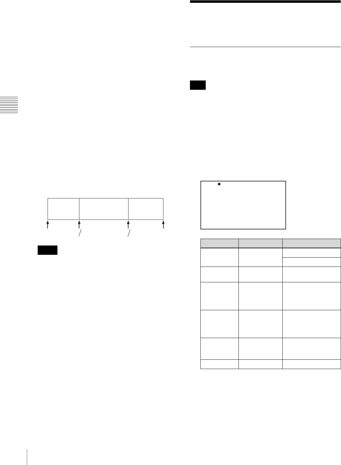
58 Recording – Basic Operations
Chapter 3 Recording and Playback
12
Set up the VDR section according to your shooting
objects, then start recording by pressing the REC
button.
• During recording, the REC/TALLY indicator in the
viewfinder lights, and “REC” appears on the
viewfinder screen.
• You can use the AUDIO LEVEL knob on the front
of the camcorder to manually adjust the channel 1
audio level. To do this, you must first set up the VDR
section to enable manual adjustment of the audio
recording level (see page 65).
13
To pause recording, press the REC button again.
The REC/TALLY indicator in the viewfinder goes off.
The material recorded from step 12 to step 13 is saved
as a single clip.
To play back the recorded clip
Press the PREV button, then press the PLAY/PAUSE
button to play from the beginning of the clip.
14
Repeat steps 12 and 13 as required to continue
shooting.
Successive clips are recorded on the disc.
• It is not possible to record a clip shorter than 2
seconds. If you stop recording within 2 seconds of
starting, this results in a 2-second clip.
If you stop recording and restart within 2 seconds of
the original start, this creates a single continuous clip
from the original start time.
• The maximum number of clips that can be recorded
on a single disc is 300. If an attempt is made to
record more than 300 clips, the error message “DISC
FULL!” appears, even if there is free capacity on the
disc.
Recording – Basic
Operations
Selecting the Recording Format
Before recording, select the recording format.
There are restrictions on the recording formats that can be
combined on a single disc.
(How to select an item in the menu screen: Turn the
MENU knob to move the b mark to the desired item.)
1
Display the FORMAT page of the USER (or
OPERATION) menu, and press the MENU knob.
For details of menu operations, see “Basic Menu
Operations” on page 131.
2
Select the desired item, and press the MENU knob.
3
Turn the MENU knob to select the desired setting, and
press the MENU knob.
4
If you have changed the setting of SYSTEM or
COUNTRY, power off the unit, then power on again.
Notes
REC
START
REC
STOP
REC
START
REC
STOP
REC
START
REC
STOP
Clip 1 Clip 2 Clip 3
Note
Item Description Settings
SYSTEM Frame
frequency NTSC: 60I/30P/23.9P
PAL: 50I/25P
REC
FORMAT Recording
format MPEG HD/DVCAM
BIT RATE
(HD) Bit rate for HD
recording HQ/SP/LP !+,-$
.#/&01"2$"##$/3#$/&41#$
/0/1#.$560/$-&/#$"#//07'$
&7.$-#8,-.07'$/09#:;*
AUDIO CH
(HD) Number of
audio channels
for HD
recording
2ch/4ch
ASPECT
RATIO Aspect ratio for
DVCAM
recording
16:9/4:3
COUNTRY Region of use NTSC/PAL
TO P 0 01 FO RM AT
S YSTEM : 6 0I
R EC FO RM AT : M PE G HD
B IT RA TE ( HD) : SP
A UDIO CH ( HD) : 4 ch
A SPECT R AT IO(DV ): 16 :9
C OUNTR Y : NTS C( J) AR EA
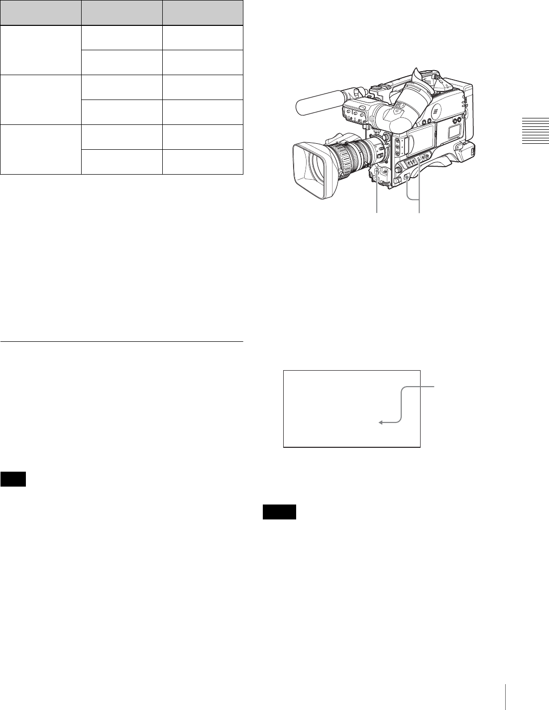
59
Recording – Basic Operations
Chapter 3 Recording and Playback
5
Repeat steps 2 to 4 to set the all of the desired items.
Bit rate setting and recording time
a) In HQ mode or LP mode, as a result of MPEG2 compression, the recording
time varies depending on the volume of the generated compressed image
data, with the above figures as a minimum. For example, in material with
little movement, the recording time may be significantly longer than
shown above.
Combining recording formats on a single disc
If any of the following items is set differently, recordings
cannot be combined on a single disc.
• SYSTEM
• REC FORMAT
• AUDIO CH
• COUNTRY
Adjusting the Black Balance/White
Balance
To ensure excellent image quality when using this
camcorder, conditions may require that both the black
balance and the white balance be adjusted.
If the black balance or white balance adjustment is started,
messages that report on the progress and results are
displayed on the viewfinder screen.
Black balance and white balance adjustment values that
are automatically set by the camcorder and the various
settings are stored in the camcorder memory and retained
even when the power is turned off.
To adjust the black balance
The black balance will require adjustment in the following
cases.
• When the camcorder is used for the first time
• When the camcorder has not been used for a long time
• When the camcorder is used under conditions in which
the surrounding temperature has changed greatly
• When the GAIN switch (L/M/H) values have been
changed on the GAIN SW page of the OPERATION
menu
It is not usually necessary to adjust the black balance when
using the camcorder after it has been off.
In automatic black balance mode, adjustments are
performed in the following order: clamp level, black set,
and black balance.
1
Power the camcorder on, and set the OUTPUT/DCC
switch to CAM.
2
Push the AUTO W/B BAL switch to BLK and release
the switch.
The switch returns to the center position, and the
adjustment is executed.
During adjustment, the following message is displayed
on the viewfinder screen.
The black balance adjustment ends in a few seconds
with the message “ABB: OK” and the adjustment
value is automatically stored in memory.
• During the black balance adjustment, the iris is
automatically closed.
• During the black balance adjustment, the gain selection
circuit is automatically activated so you may see
flickering on the viewfinder screen, but this is not a
malfunction.
Bit rate Audio channels
used
Recording time
HQ mode a)
Variable bit rate,
upper limit 35
Mbps
4 channels At least 65
minutes
2 channels At least 68
minutes
SP mode
Fixed bit rate, 25
Mbps
4 channels At least 85
minutes
2 channels At least 90
minutes
LP mode a)
Variable bit rate,
upper limit 18
Mbps
4 channels At least 112
minutes
2 channels At least 122
minutes
Note
Notes
2 1
AB B: EXECU TI NG
- BL AC K SET -
The messages
change in the
following
sequence:
-BLACK SET-
r
-BLACK
BALANCE-
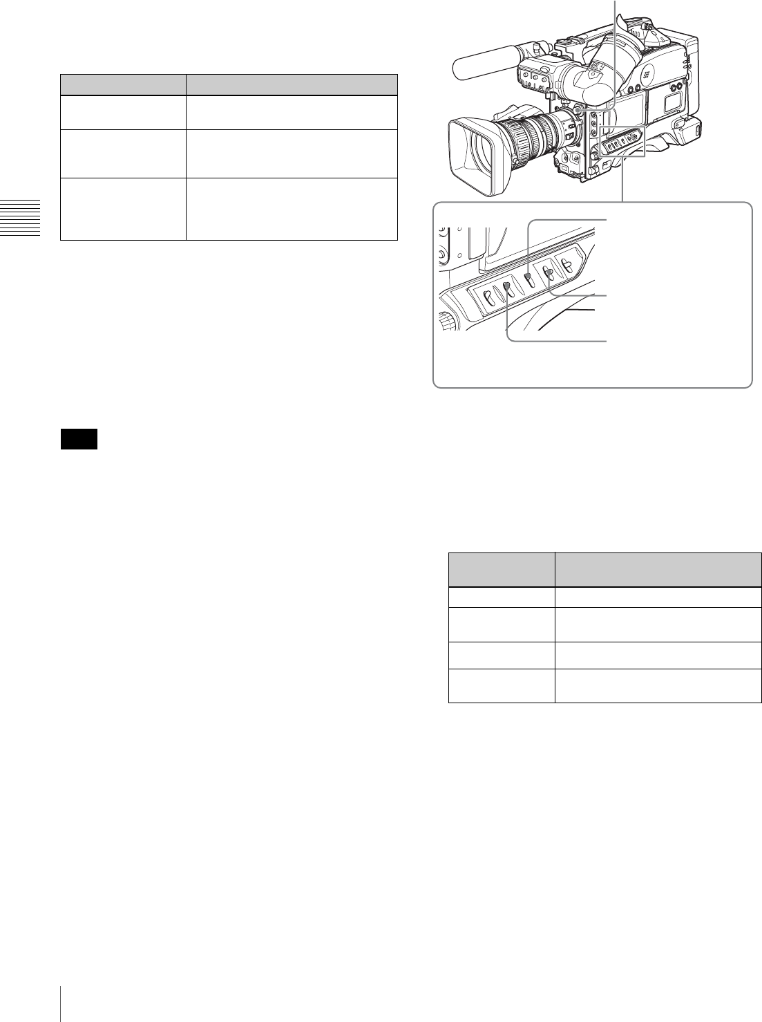
60 Recording – Basic Operations
Chapter 3 Recording and Playback
If automatic black balance adjustment cannot be
made
If the black balance adjustment cannot be completed
normally, an error message will appear for about 3 seconds
on the viewfinder screen.
If any of the above error messages is displayed, retry the
black balance adjustment. Keep pushing the WHT/BLK
switch to BLK until “-BLACK SET-” appears after “-
BLACK BALANCE-” appears. If the error message
occurs repeatedly, contact your Sony dealer.
To adjust the white balance
It is necessary to adjust the white balance each time the
principal lighting source changes.
When this unit is operating in EZ mode, the ATW function
(see page 62) is forced to ON.
1
Set the switches and selectors as shown in the figure
below.
a) White balance setting values are stored in memory B only when the
WHITE SWITCH <B> item is set to MEM on the WHITE SETTING
page of the MAINTENANCE menu.
2
Set the FILTER selector and the 5600K button to suit
the lighting conditions.
The following table shows which FILTER selector
setting you should use depending on the lighting
conditions.
If the setting of the FILTER selector is changed, a
message reporting the new setting appears for about 3
seconds in the setting change and adjustment progress
message display area of the viewfinder screen.
3
Place a white test card under the same lighting
conditions as for the subject to be shot and zoom up to
it.
Alternatively, any white object such as a cloth or a
wall can be used.
The absolute minimum white area is as follows.
Error message Meaning
ABB: NG
IRIS NOT CLOSED The lens iris did not close. Check if
the lens cable is connected properly.
ABB: NG
TIME LIMIT Adjustment could not be completed
within the standard number of
attempts.
ABB: NG
R (or G or B):
OVERFLOW
The difference between the
reference value and the current
value is so great that it exceeds the
range.
Note
FILTER selector
setting
Lighting conditions
1 (CLEAR) Indoor shooting
2 (1/4 ND) Cloudy or rainy outdoor shooting, or
to reduce the depth of field
3 (1/16 ND) Sunlight
4 (1/64 ND) To reduce the depth of field in
sunlight
FILTER selector
WHITE BAL switch: A or B a)
OUTPUT/DCC switch: CAM
GAIN switch: Set as low as
possible.
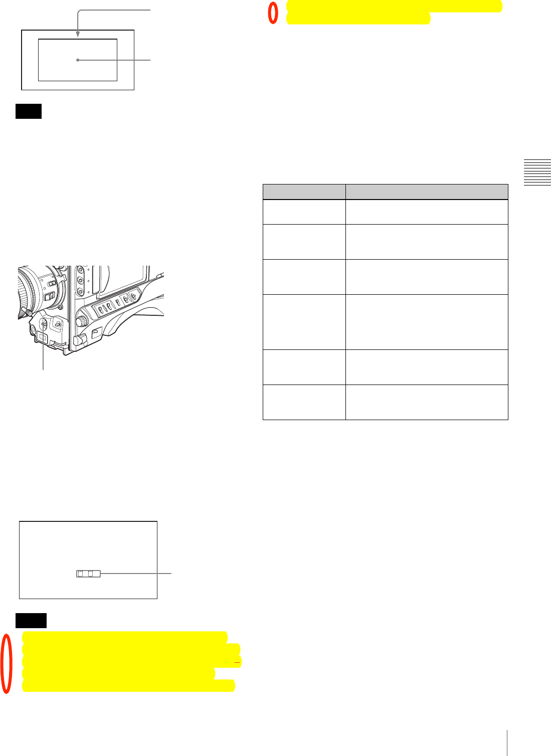
61
Recording – Basic Operations
Chapter 3 Recording and Playback
Make sure there are not bright spots in the rectangle.
4
Adjust the lens iris.
Manually adjusted lens: Set the iris to an appropriate
setting.
Lens with automatic iris: Set the automatic/manual
switch on the lens to automatic.
5
Push the AUTO W/B BAL switch to WHT, and then
release the switch.
The switch returns to the center position, and the
adjustment is executed.
During adjustment, the message “AWB:
EXECUTING” is displayed on the viewfinder screen.
The white balance is adjusted in about one second, and
the message “AWB: OK” appears. The adjustment
setting is automatically stored in the memory (A or B)
that was selected in step 1.
• The color temperature display that appears after
white balance adjustment is calculated on the basis
of the R/G/B signal output from the camera. It may
not agree with the results of measurement by
commercially available color temperature meters.
The camcorder’s color temperature display should
be regarded as an approximation.
• If the camera has a zoom lens with an automatic iris,
the iris may hunt 1). To prevent this, adjust the iris
gain knob (indicated as IG, IS, or S) on the lens.
For details, refer to the lens operation manual.
1) Hunting: Repeated brightening and darkening of the image,
resulting from repeated response to automatic iris control.
If the automatic white balance adjustment cannot
be made
If the white balance adjustment cannot be completed
normally, an error message will appear for about 3 seconds
on the viewfinder screen.
If any of the above error messages is displayed, retry the
white balance adjustment. If the error message occurs
repeatedly, contact your Sony dealer.
If you have no time to adjust the white balance
Set the WHITE BAL switch to PRST.
The white balance is automatically set as follows,
depending on the state of the 5600K button.
• 5600K button lit: 5600K
• 5600K button not lit: 3200K
About the white balance memory
Values stored in memory are held until the white balance
is next adjusted.
There are two sets of white balance memories, A and B,
which you can switch between with the WHITE BAL
switch (PRST/A/B).
On the WHITE SETTING page of the MAINTENANCE
menu, when WHT FILTER INH is set to OFF, there are
two memories, A and B for each position of the ND filter
of this unit (CLEAR, 1/4 ND, 1/16 ND, and 1/64 ND).
In this case, the memory is switched as you change the ND
filter position, for a total of eight (4×2) memories.
Note
Notes
Rectangle centered on
the screen. The lengths
of the sides are 70% of
the length and width of
the screen.
The white object must
be within the rectangle
and have an area of at
least 10% of the screen.
AUTO W/B BAL switch
A WB :OK
. K
Approximate color
temperature of the
subject
Error message Meaning
AWB: NG
LOW LEVEL The white video level is too low. Either
open the lens iris or increase the gain.
AWB: NG
COLOR TEMP
HIGH
The color temperature is too high.
Select a suitable setting for the 5600K
button.
AWB: NG
COLOR TEMP
LOW
The color temperature is too low. Use
the 5600K button for proper setting.
AWB: NG
TIME LIMIT Adjustment could not be completed
within the standard number of
attempts. Try to adjust again. If
adjustment fails a few times, contact
your Sony dealer.
AWB: NG
POOR WHITE
AREA
The white area could not be checked.
AWB: NG
OVER LEVEL The white video level is too high. Either
stop down the lens iris or change the
ND filter.

62 Recording – Basic Operations
Chapter 3 Recording and Playback
If a memory error occurs
If the error message “: STORED DATA: NG” flashes on
the viewfinder screen when the camcorder is turned on, the
white balance memory contents have been lost. Adjust the
white balance again. Contact your Sony dealer if this
message continues to appear even after the white balance
has been adjusted again.
Using the ATW (auto tracking white
balance) function
By using the ATW function, the white balance is adjusted
automatically when the lighting conditions change.
Depending on the shooting conditions, the white balance
may not always be correctly adjusted automatically. To get
a precise white balance, it is recommended to use the
WHITE BAL switch.
Turning the ATW function on using the WHITE
BAL switch
1
On the WHITE SETTING page of the
MAINTENANCE menu, set WHITE SWITCH <B>
to ATW.
2
Set the WHITE BAL switch to the B(ATW) position.
This turns the ATW function on, and the white balance
is now adjusted automatically to respond to changes in
the lighting conditions.
Turning the ATW function on using an ASSIGN
switch
1
On the ASSIGNABLE page of the USER (or
OPERATION) menu (see page 142), set one of
ASSIGN 1 to ASSIGN 4 to ATW.
2
Press the ATW-assigned switch.
This turns the ATW function on, and the white balance
is now adjusted automatically to respond to changes in
the lighting conditions.
Setting the Electronic Shutter
This section describes the shutter modes that can be used
with the electronic shutter of the camcorder, and describes
the procedure for selecting the shutter speed and shutter
mode.
About the shutter modes
The shutter modes that can be used with the electronic
shutter and the shutter speeds that can be selected are listed
below.
• Whatever the operating mode of the electronic shutter,
the sensitivity of the CCD decreases with increasing
shutter speed.
• When the automatic iris is used, the iris opens wider as
the shutter speed increases, thus reducing the depth of
field.
• Under artificial light, particularly fluorescent or mercury
lamps, the light intensity may appear to be constant, but
the red, green, and blue intensities are actually changing
in synchronization with the frequency of the power
supply causing flicker. Using an electronic shutter under
such lighting could make the flicker even worse. Color
flicker is particularly likely to happen when the power
supply frequency is 60 Hz. However, if the power
frequency is 50 Hz, setting the shutter speed to 1/100 can
reduce this flicker.
Note
Shutter
mode
Frame
frequency
Shutter speed Application
Standard 60i 1/100, 1/125,
1/250, 1/500,
1/1000, 1/2000
(sec.)
For shooting
fast-moving
subjects with
little blurring.
30P 1/40, 1/60, 1/120,
1/125, 1/250,
1/500, 1/1000,
1/2000 (sec.)
23.98P 1/32, 1/48, 1/96,
1/125, 1/250,
1/500, 1/1000,
1/2000 (sec.)
50i 1/60, 1/125, 1/250,
1/500, 1/1000,
1/2000 (sec.)
25P 1/33, 1/50, 1/100,
1/125, 1/250,
1/500, 1/1000,
1/2000 (sec.)
ECS
(Extended
Clear
Scan)
60i 60.0 to 6000 Hz For obtaining
images with
no horizontal
bands of
noise when
shooting
subjects such
as monitor
screens.
30P 30.0 to 7000 Hz
23.98P 24.0 to 5000 Hz
50i 50.0 to 6000 Hz
25P 25.0 to 6000 Hz
SLS
(Slow
Speed
Shutter)
(except
23.98P) 2 to 8, 16 , 32, 64
frames
(1/15 to 1/3.8,
1/1.9, 1.1, 2.1
(sec.))
For shooting
subjects in
low level
lighting
conditions.
Notes
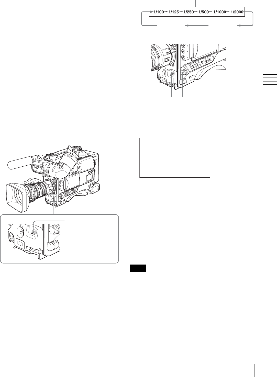
63
Recording – Basic Operations
Chapter 3 Recording and Playback
• When a bright object is shot in ECS mode in such a
manner that it fills the screen, the upper edge of the
picture may have poor quality because of an inherent
characteristic of CCDs. Before using ECS mode, check
the shooting conditions.
To select the shutter mode and shutter
speed
Use the SHUTTER switch to select a shutter mode or a
standard-mode shutter speed. To set the shutter speed in
ECS or SLS mode, with the SHUTTER switch set to ON
and the ECS or SLS mode selected, use the MENU knob
for adjustment.
To set the shutter mode and the standard-mode
shutter speed
Once the shutter speed is selected, it is retained even when
the camcorder is turned off.
1
Make sure that neither menu nor status display is
shown.
2
Push the SHUTTER switch from ON to SEL.
The current shutter setting indication appears for about
3 seconds in the setting change and adjustment
progress message display area of the viewfinder
screen.
Examples: “: SHUTTER: 1/250”, “: ECS: 60.0 Hz”,
“: SLS: 1/30: 1FRAME”
3
Before the shutter setting indication in step 2
disappears, push the SHUTTER switch to SEL again.
Repeat this until the desired mode or speed appears.
To set the shutter speed in ECS mode
1
Carry out the steps in “To set the shutter mode and the
standard-mode shutter speed” on page 63 to set the
shutter mode to ECS.
2
Turn the MENU knob until the desired frequency
appears.
The selectable frequency range varies depending on
the recording format. See the table under “About the
shutter modes” on page 62.
When the RM-B150 Remote Control Unit is
connected
You can set the shutter speed in ECS mode with the rotary
encoder of the RM-B150.
To set the shutter speed in SLS mode
• When EZ mode is selected, SLS mode is forcibly
deselected.
• When you start recording under the following conditions
with the camcorder in SLS mode, a certain number of
black frames are recorded at the top of the recorded clip.
The number of black frames depends on the SLS setting.
- During disc playback
- During thumbnail display (page 82)
• In SLS mode, slow & quick-motion functions are not
available.
SHUTTER switch
Notes
Example display of standard mode (when the scan mode
is set to 60i)
SLS mode ECS mode
1 2
EC S: 60.00 Hz
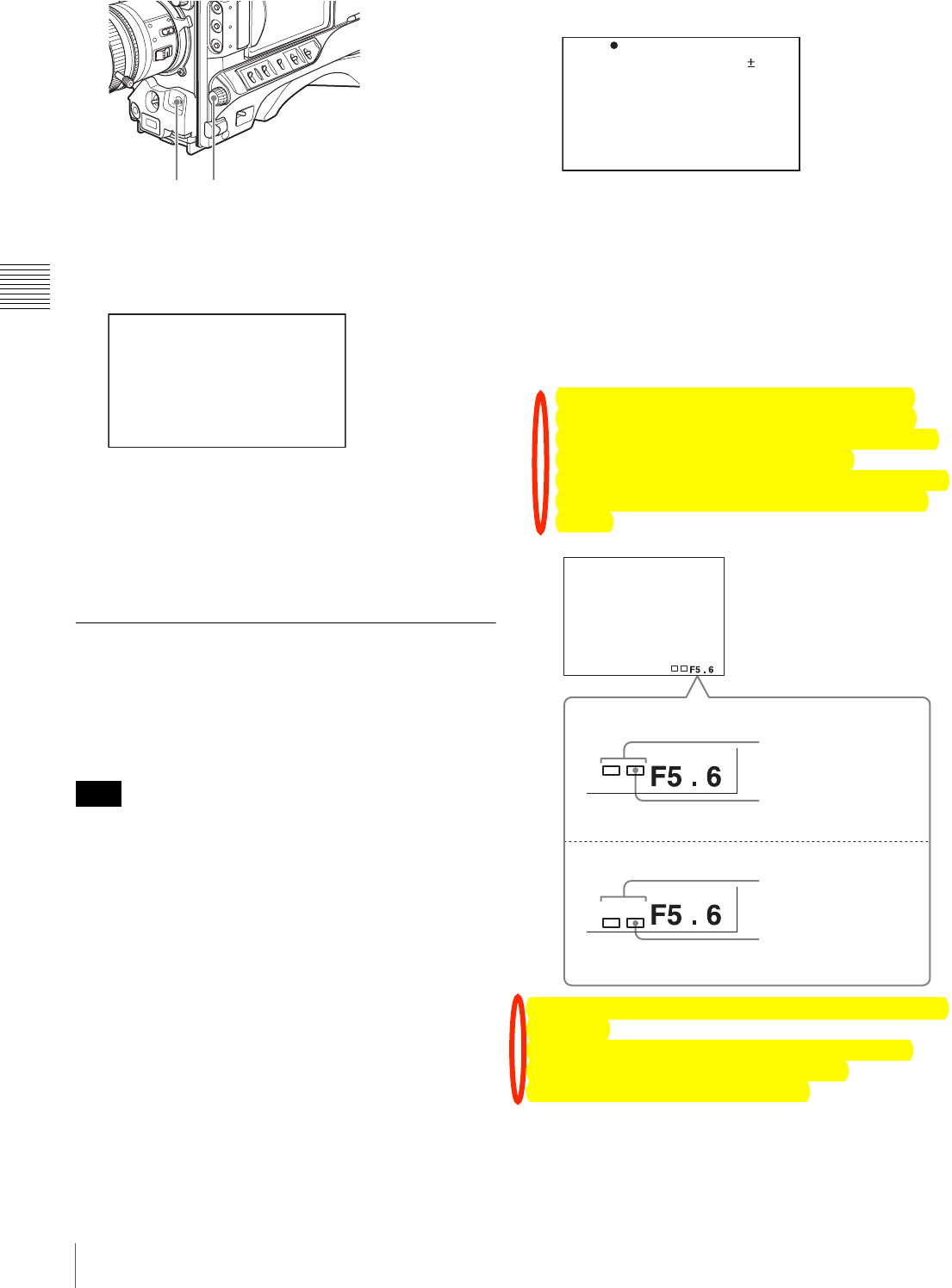
64 Recording – Basic Operations
Chapter 3 Recording and Playback
1
Carry out the steps in “To set the shutter mode and the
standard-mode shutter speed” on page 63 to set the
shutter mode to SLS.
2
Turn the MENU knob until the desired number of
frames appears.
The number of frames can be set to values in the range
2 to 8, 16, 32, and 64 (1 frame nearly equals to 1/30
second).
Adjusting the Iris
Turning the auto iris function on and off
When the lens IRIS switch is in the A position, the auto iris
function is on; when in the M position the function is off.
When this unit is operating in EZ mode, the auto iris is
forced ON.
To set the automatic iris
The reference value for automatic iris adjustment can be
changed to aid the shooting of clear pictures of back-lit
subjects, or to prevent blown-out highlights.
To change the reference value
(How to select an item in the menu screen: Turn the
MENU knob to move the b mark to the desired item.)
1
Set A.IRIS to ON on the PAINT page of the PAINT
menu, and press the MENU knob.
For details on menu operations, see “Basic Menu
Operations” on page 131.
2
Select A.IRIS, and press the MENU knob.
3
Turn the MENU knob to select the reference value
from the following, and press the MENU knob.
• +0.5: about 0.5 stop further open
• +1.0: about 1 stop further open
•#0: standard value
•– 0.5: about 0.5 stop further closed
•–1.0: about 1 stop further closed
The changed reference value is retained until the
power of the camcorder is turned off. Even if the
reference value is changed, it reverts to the standard
value every time the power is turned on.
If the reference value is set to other than the ±0 value,
the following indications appear on the viewfinder
screen.
If you want to change the reference value during
shooting
You can change the reference value by MENU knob
operations only, without opening the menu.
In this case, note the following points.
Note
1 2
SLS: 1 /1 5 : 2 FR AM E
TOP P01 PAINT
A .IRIS : 0
D ETAIL L EV EL : 0
M ASTER B LC AK : 0
G AMMA SE LE CT : 0
M ASTER G AM MA : S TD
B LACK GA MM A : 0
P RESET M TX SEL : S TD
Opening the lens iris
Stopping down the lens iris
Iris opened by 1 stop
(two bars)
Iris opened by 0.5 stop
(one bar)
Iris stopped down by 1
stop (two bars)
Iris stopped down by 0.5
stop (one bar)
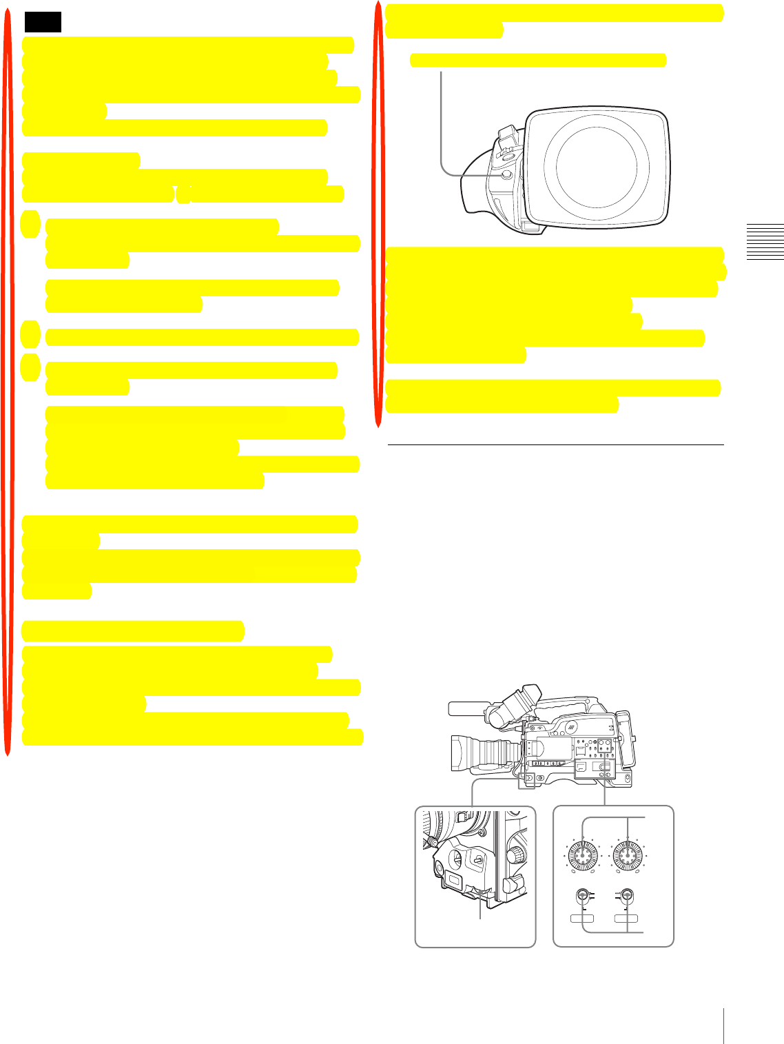
65
Recording – Basic Operations
Chapter 3 Recording and Playback
When setting the shutter speed while the shutter mode is
set to ECS or SLS, the setting of shutter speed takes
priority (see page 63). To change the reference value,
make sure the camcorder is not in the process of setting the
shutter speed.
Check that the slow & quick-motion function is off.
Proceed as follows.
(How to select an item in the menu screen: Turn the
MENU knob to move the b mark to the desired item.)
1
Display the CAM CONFIG page of the
MAINTENANCE menu (see page 124), and press the
MENU knob.
For details on menu operations, see “Basic Menu
Operations” on page 131.
2
Select IRIS OVERRIDE, and press the MENU knob.
3
Turn the MENU knob to select ON, and press the
MENU knob.
This enables the function that adjusts the reference
value during shooting. You can adjust the value by
simply turning the MENU knob.
Leaving the MENU knob in the current position for a
few seconds sets the reference value.
When the RM-B150/B750 Remote Control Unit is
connected
The IRIS control knob of the RM-B150/B750 can be used
for lens iris setting. In this case, the bar display (s) does
not appear.
To adjust the iris sensitivity
When you use the VCL-719BXS lens (supplied with
PDW-F330K), you usually need not adjust the iris
sensitivity because lenses are equipped with iris sensitivity
adjustment function.
In auto iris mode, if hunting or response delay happens,
adjust the iris sensitivity using the iris sensitivity trimmer.
Example for the lens (VCL-719BXS) supplied with
the PDW-F330K:
You can see the iris sensitivity trimmer when removing the
rubber cap on the front of the lens driving unit. Use a mini-
screwdriver to turn the trimmer. If you turn it clockwise,
the sensitivity increases, and if you turn it
counterclockwise, the sensitivity decreases.
It is recommended that you confirm the iris sensitivity
after replacing the lens.
For more information, refer to the operating instructions
for the lens (or consult the lens maker).
Adjusting the Audio Level
Setting the AUDIO SELECT (CH-1/CH-2) switches to
AUTO automatically adjusts the input levels of the audio
signal to be recorded in audio channels 1 and 2.
To manually adjust the levels of the audio
inputs from the AUDIO IN CH-1/CH-2
connectors
Proceed as follows to adjust the levels of the audio inputs
from the AUDIO IN CH-1/CH-2 connectors, which are to
be recorded in audio channels 1 and 2.
Note
Iris sensitivity trimmer (S or IRIS GAIN is indicated.)
AUTO
CH-1
MANUAL
AUDIO SELECT
AUDIO LEVEL
0 10 0 10
CH-2
32
3
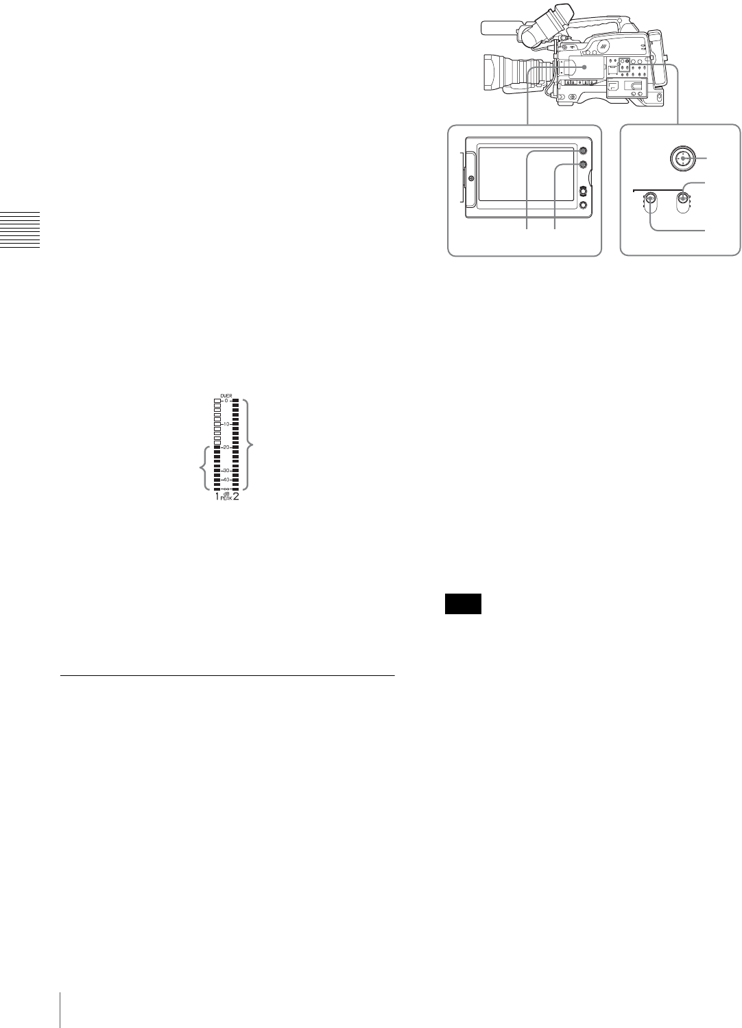
66 Recording – Basic Operations
Chapter 3 Recording and Playback
1
Select the audio channel that you want to record in.
For details, see “Selection of the recording audio
input” on page 49.
2
Set the AUDIO SELECT (CH-1/CH-2) switch(es)
corresponding to the audio channel(s) selected in step
1 to MANUAL.
3
With the AUDIO LEVEL knob on the side control
panel and the AUDIO LEVEL knob on the front,
adjust so that the audio level meter shows up to –20 dB
for a normal input volume.
The input level value of the audio channel 1 is the
value of the AUDIO LEVEL CH-1 knob on the side
control panel multiplied by the value of the AUDIO
LEVEL knob on the front.
The input level value of the audio channel 2 is the
value of the AUDIO LEVEL CH-2 knob.
When the top bar (0 dB) turns on, the audio level is too
high. There is no problem if the second bar from the
top turns on.
To adjust manually the level of audio channel 1
without using the AUDIO LEVEL knob on the
front of the camcorder
Set AUDIO CH1 LEVEL to SIDE1 on the AUDIO-1 page
of the MAINTENANCE menu.
The setting of the AUDIO LEVEL knob on the front of the
camcorder is disabled.
Setting the Time Data
To set the timecode
The timecode setting range is from 00:00:00:00 to
23:59:59:29 (hours: minutes: seconds: frames).
(When the frame frequency is 23.98P: from 00:00:00:00 to
23:59:59:23)
1
Press the DISPLAY/EXPAND button of the LCD
monitor so that the status display appears.
2
Press the COUNTER/CHAPTER button of the LCD
monitor to display TCG on the time counter display
section.
3
Set the PRESET/REGEN/CLOCK switch to PRESET.
4
Set the F-RUN/SET/R-RUN switch to SET.
The first (leftmost) digit of timecode flashes.
5
Use the SEL/SET button (four-way arrow key) to set
the timecode value including the last (rightmost) digit
of the timecode.
To reset the timecode value to 00:00:00:00, press the
RESET button on the right side of the LCD monitor.
When the frame frequency of this unit is 23.98P, a
timecode frame count can only be set to a multiple of
4 (0, 4, 8, 12, 16, or 20).
6
Set the F-RUN/SET/R-RUN switch to the desired
operating mode for the timecode generator.
F-RUN: Free run. The timecode generator keeps
running.
R-RUN: Recording run. The timecode generator runs
only while recording.
To set the DF (drop-frame)/NDF (non-drop-frame)
mode
You can select the drop-frame (DF) mode or non-drop-
frame (NDF) mode on the TIME CODE page of the
MAINTENANCE menu.
These bars turn on.
Normal input level Excessive input level
All bars turn on.
Note
PRESET F-RUN
REGEN SET
CLOCK R-RUN
SUB CLIP
CLIP MENU
SEL/SET
1 2 3
5
4,6
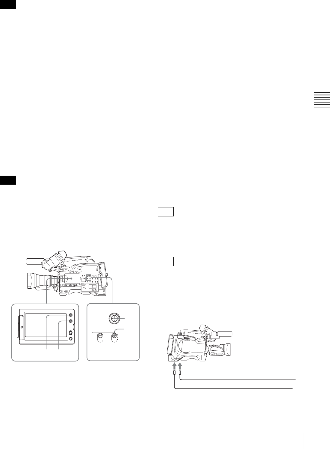
67
Recording – Basic Operations
Chapter 3 Recording and Playback
When the frame frequency of this unit is 23.98P, recorded
timecode is always non-drop-frame (NDF).
To make the timecode consecutive
When the F-RUN/SET/R-RUN switch is set to R-RUN,
recording a number of scenes to the disc normally
produces consecutive timecode. However, once you
remove the disc and record to another disc, the timecode
will no longer be contiguous even when you use again the
original disc for recording.
In this case, by setting the PRESET/REGEN/CLOCK
switch to REGEN, the timecode can be made continuous.
To save the actual time in the timecode
Setting the PRESET/REGEN/CLOCK switch to CLOCK
saves the actual time in the timecode. When it is necessary
to set the actual time, use the TIME/DATE page of the
OPERATION menu.
For details, see “Setting the Date and Time of the Internal
Clock” on page 39.
When the frame frequency of this unit is 23.98P, the
recorded timecode does not coincide with real time.
To set the user bits
By setting the user bits (up to 8 hexadecimal digits), you
can record user information such as the date, time, or scene
number on the timecode track.
1
Press the DISPLAY/EXPAND button of the LCD
monitor so that the status display appears.
2
Press the COUNTER/CHAPTER button on the LCD
monitor to display UBG in the time counter display
section.
3
Set the PRESET/REGEN/CLOCK switch to PRESET.
4
Set the F-RUN/SET/R-RUN switch to SET.
The first (leftmost) digit flashes.
5
Use the SEL/SET button (four-way arrow key) to set
the timecode value including the last (rightmost) digit
of timecode.
Hexadecimal digits A to F are displayed as A to F in
capital letters.
To reset the timecode value to 00 00 00 00, press the
RESET button on the right side of the LCD monitor.
6
Set the F-RUN/SET/R-RUN switch to the desired
operating mode for the timecode generator.
F-RUN: Free run. The timecode generator keeps
running.
R-RUN: Recording run. The timecode generator runs
only while recording.
To lock the timecode to an external source
You can synchronize the internal timecode generator of
this camcorder with an external generator for the
regeneration of an external timecode. You can also
synchronize the timecode generators of other camcorders/
VTRs with the internal generator of this camcorder.
Input the timecode to the TC connector on the rear
connector panel, and set the IN/OUT selector switch to IN.
When using this unit as the reference device, set the IN/
OUT selector switch to OUT, to output timecode from the
TC connector.
Input the timecode to the TC IN connector on the left side.
Connections for timecode synchronization
Connect both the reference video signal and the external
timecode as illustrated below.
Example 1: Synchronizing with an external timecode
Note
Note
PRESET F-RUN
REGEN SET
CLOCK R-RUN
SUB CLIP
CLIP MENU
SEL/SET
4
3,5
1 2
F330
F350
GENLOCK IN
External timecode
TC IN
Reference video signal (SD or HD)
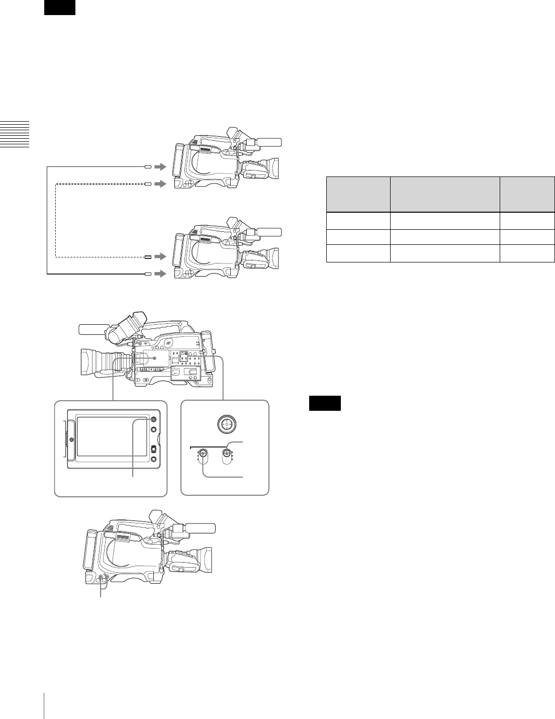
68 Recording – Basic Operations
Chapter 3 Recording and Playback
Example 2: Connecting two units, and using one as the
reference
• When making the following connections, set the frame
frequency to the same value on both units. Wait until the
reference camcorder becomes stable (a state where a
normal picture appears on the viewfinder screen or the
LCD monitor), and then connect the other camcorders.
• When the frame frequency of this unit is 23.98P, make
sure that the reference unit is either recording or in the
recording stopped state.
To synchronize the timecode
1
Set the PRESET/REGEN/CLOCK switch to PRESET.
2
Set the F-RUN/SET/R-RUN switch to F-RUN.
3
Press the DISPLAY/EXPAND button of the LCD
monitor to display TCG on the time counter display
section.
4
Depending on the frame frequency setting of this unit,
supply the reference timecode and reference video
signal shown in the following table to the TC IN
connector 1) and GENLOCK IN connector,
respectively. The input reference timecode and
reference video signal must meet the phase
relationship requirements of the the SMPTE timecode
standard. (Excluding the case where the frame
frequency is 23.98P.)
1) On the PDW-F350, input to the TC IN connector. On the PDW-F330,
input to the TC connector, and set the IN/OUT selector switch to IN.
a) More precisely 59.94i
b) More precisely 29.97P
c) Genlock is not possible on a 23.98PsF video signal.
This operation synchronizes the internal timecode
generator with the external timecode. After about 10
seconds, you can disconnect the external timecode
without losing the synchronization. However, there
will be noise on the recorded image if you connect or
disconnect the timecode signal during recording.
• When the frame frequency of this unit is 23.98P, a
discrepancy of ±1 frame with the externally locked
timecode may arise.
• When you finish the above procedure, the internal
timecode is immediately synchronized with the external
timecode and the time counter display will show the
value of the external timecode. However, wait for a few
seconds until the sync generator stabilizes before
recording.
• If this unit cannot be genlocked to the reference video
signal, the internal timecode is not correctly
synchronized with the external timecode.
Until this unit is genlocked to the input reference video
signal, the output video signal from this unit may break
up.
• When the internal timecode generator is set to F-RUN
mode, the precision of the synchronization may be
reduced if you turn the POWER switch off and on or
keep the camcorder turned off for a long time.
Notes
Reference camcorder
MONITOR OUT
TC OUT
GENLOCK IN
TC IN
PRESET F-RUN
REGEN SET
CLOCK R-RUN
SUB CLIP
CLIP MENU
SEL/SET
1
2
3
4
Frame
frequency of
this unit
Acceptable reference
video signal frame
frequency (HD or SD)
Acceptable
timecode
60i a), 30P b) 59.94i 30 frames
50i, 25P 50i 25 frames
23.98P 59.94i c) 24 frames
Notes

69
Recording – Basic Operations
Chapter 3 Recording and Playback
About user bits settings during timecode
synchronization
When the timecode is synchronized, only the time data is
synchronized with the external timecode value. Therefore,
the user bits can have their own settings for each
camcorder.
To release the timecode synchronization
First disconnect the external timecode, then set the F-
RUN/SET/R-RUN switch to R-RUN.
To change the power supply from the battery
pack to an external power supply during
timecode synchronization
To maintain a continuous power supply, connect the
external power supply to the DC IN connector before
removing the battery pack. You may lose timecode
synchronization if you remove the battery pack first.
Camera synchronization during timecode
synchronization
During timecode synchronization, the camera is genlocked
to the reference video signal input from the GENLOCK IN
connector.
Setting for Special Shooting Cases
Depending on the shooting conditions, set the camcorder
appropriately referring to the following table.
To correct skin detail
You can specify a color other than a skin tone to adjust the
color.
1
Set SKIN AREA IND to ON on the SKIN DETAIL
page of the PAINT menu.
For details on menu operations, see “Basic Menu
Operations” on page 131.
2
Set SKIN DETECT on the SKIN DETAIL page of the
PAINT menu.
This causes the area detect cursor to be shown in the
viewfinder screen.
3
Place the area detect cursor on the target, then execute
SKIN DETECT.
This designates the correction area, which is indicated
by a zebra pattern.
4
Change the value of SKIN DTL WIDTH (0 to 359) on
the SKIN DETAIL page so that the zebra pattern may
be displayed in the target area.
Set the correction level beforehand using the SKIN
DETAIL LVL item on the SKIN DETAIL page.
5
When the setting is finished, set SKIN AREA IND to
OFF on the SKIN DETAIL page.
Deleting Clips
With this camcorder you can delete clips one at a time, in
sequence from the last recorded clip, or you
can delete all clips in a single operation.
You can use the THUMBNAIL menu to delete the selected
clip or all clips. For details, see “Deleting Clips” on
page 88.
Locked clips cannot be deleted.
To delete the last recorded clip
Proceed as follows.
(How to select an item in the menu screen: Turn the
MENU knob to move the b mark to the desired item.)
1
Display the DISC page of the USER (or
OPERATION) menu (see page 55), and press the
MENU knob.
2
Select DELETE LAST CLIP, and press the MENU
knob.
The message “DELETE OK? YES b NO” appears.
3
To execute the deletion, select YES, and press the
MENU knob again.
The last recorded clip is deleted.
4
By repeating steps 2 and 3, you can delete any number
of clips in sequence from the last recorded clip.
Shooting
conditions
Setting and effect
When adjusting
for skin detail or
tone (Example:
When shooting
to hide skin
details)
Setting: See 5<,$8,--#8/$"=07$.#/&01:$,7$
%&'# >?.
Effect: This adjusts the skin detail or
tone to a designated active area.
The 3200K
preset white
balance makes
the picture
reddish.
Setting: Change the setting of the preset
white balance on the PRESET WHT
page of the MAINTENANCE menu.
Effect: This prevents the picture from
reddening.
Note

70 Recording – Basic Operations
Chapter 3 Recording and Playback
To delete all clips within the disc
The following procedure deletes all unlocked clips.
Proceed as follows.
(How to select an item in the menu screen: Turn the
MENU knob to move the b mark to the desired item.)
1
Display the DISC page of the USER (or
OPERATION) menu (see page 55), and press the
MENU knob.
2
Select DELETE ALL CLIPS, and press the MENU
knob.
The message “DELETE OK? YES b NO” appears.
3
To execute the deletion, select YES, and press the
MENU knob.
This deletes all clips within the disc.
Recording Shot Marks
With this unit, you can record two types of shot mark (shot
mark 1 and shot mark 2) on the disc.
Recording shot marks for scenes containing important
images and sounds enables quick access to the marked
points. This increases editing efficiency.
To specify shot marks to be recorded on
the disc
To select whether or not to record shot mark 1 and shot
mark 2, use the following procedure.
With the factory default setting, both are recorded.
(How to select an item in the menu screen: Turn the
MENU knob to move the b mark to the desired item.)
1
Display the ESSENCE MARK page of the
MAINTENANCE menu, and press the MENU knob.
2
Select SHOT MARK 1 or SHOT MARK 2, and press
the MENU knob.
3
Turn the MENU knob to select ON (display the shot
mark) or OFF (do not display the shot mark), and press
the MENU knob.
Recording a SHOT MARK 1 essence mark
Press the RET button on the lens once.
“ShotMark1” appears near the timecode display on the
viewfinder screen for about one second.
If SHOT MARK 1 recording has been assigned to one of
the ASSIGN switches, you can also use that switch to
record a SHOT MARK 1 essence mark.
See “Assigning Functions to ASSIGN Switches” on
page 142 for more information about how to make
assignments.
Recording a SHOT MARK 2 essence mark
Press the RET button twice in quick succession during
recording or playback.
“ShotMark2” appears near the timecode display on the
viewfinder screen for about one second.
If SHOT MARK 2 recording has been assigned to one of
the ASSIGN switches, you can also use that switch to
record a SHOT MARK 2 essence mark.
Setting the Thumbnail Image at
Recording Time
When you record a clip, you can specify which frame to
use as the clip’s thumbnail image (page 82).
For example, if all clips have the same image in their first
frames, you can specify a frame a few seconds after the
start of the clip, so that all thumbnails will not show the
same image.
The factory default setting is to use the first frame in the
clip as the thumbnail.
Proceed as follows.
!"#$%&#%'()(*&%+,%-&(.%-,%&/(%.(,0%'*1((,2%301,%&/(%
4567%8,#9%&#%.#:(%&/(%b%.+18%&#%&/(%;('-1(;%-&(.<=
Note
Clip 1 Clip 2 Clip 3
Clips can be deleted in the sequence 3 t 2 t 1.
Note
SHOT MARK 1 : ON
SHOT MARK 2 : ON
INDEX PIC. POS. : 0SEC
TO P M 04 ES SE NC E MAR K
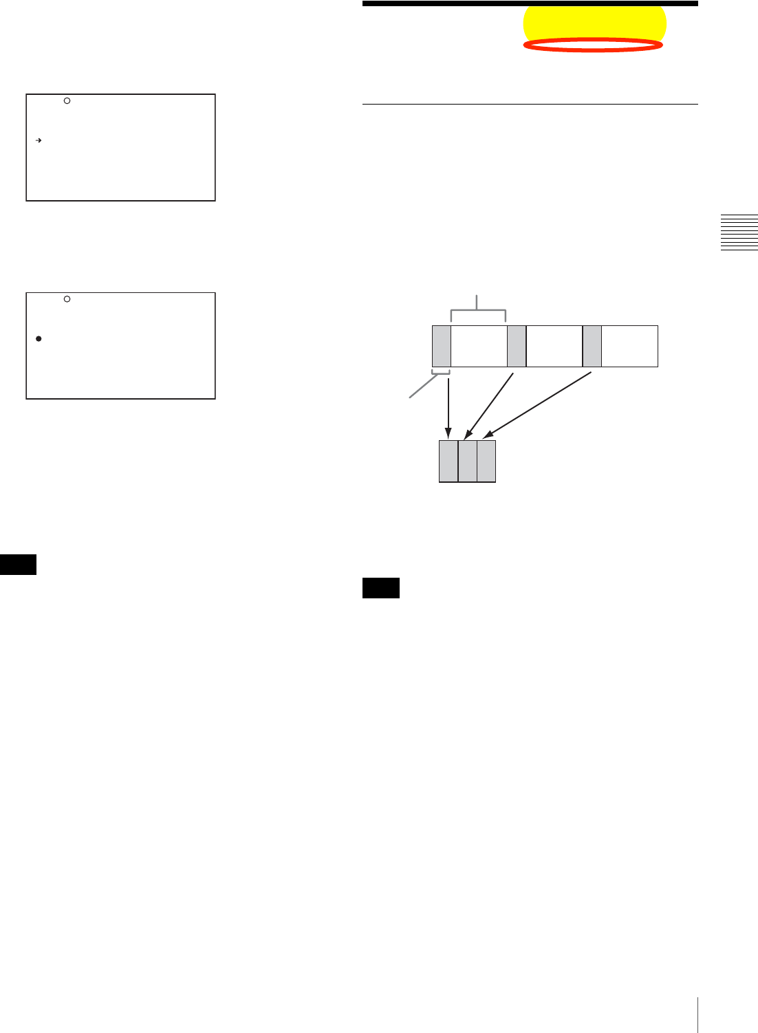
71
Recording – Advanced Operations
Chapter 3 Recording and Playback
1
Display the ESSENCE MARK page of the
MAINTENANCE menu, and press the MENU knob.
For details on menu operations, see “Basic Menu
Operations” on page 131.
2
>()(*&%?6@5A%B?C<%BD><E%+,;%F1(''%&/(%4567%8,#9<
3/(%b%.+18%*/+,G('%&#%+%z%.+18E%+,;%&/(%z%.+18%
*/+,G('%&#%+%H%.+18<
3
Turn the MENU knob to select the desired time.
You can select the time in units of 1 second over the
range 0SEC to 10SEC.
4
Press the MENU knob.
The selection is confirmed.
You can also change the thumbnail image at playback
time. For details, see “To switch the information displayed
in the thumbnail screen” on page 83.
Recording – Advanced
Operations
Time-lapse Video Recording
(“Interval Recording” Function)
The interval recording (Interval Rec) function is effective
for shooting objects that move very slowly. As shown in
the following figure, you need to set the recording time for
one recording session (NUMBER OF FRAME) and the
total time consisting of one recording session and the
following interval (INTERVAL TIME).
A pre-lighting function is available. This function
automatically turns on the light before recording starts,
which allows you to record pictures under stable light and
color temperature conditions.
When the recording mode of this unit is set to DVCAM
format, the Interval Rec function is not available.
Making settings before shooting
To record in Interval Rec mode, you need to set the related
items beforehand as follows.
(How to select an item in the menu screen: Turn the
MENU knob to move the b mark to the desired item.)
1
Set INTERVAL REC to ON on the SPECIAL
EFFECTS page of the OPERATION menu.
For details on menu operations, see “Basic Menu
Operations” on page 131.
Note
S HOT M AR K 1 : ON
S HOT M AR K 2 : ON
I NDEX PI C. POS. : 0S EC
TO P M 04 ES SE NC E MAR K
S HOT M AR K 1 : ON
S HOT M AR K 2 : ON
I NDEX PI C. POS. :? 5S EC
TO P M 04 ES SE NC E MAR K
Note
Shooting interval (INTERVAL TIME)
Recording
time for one
recording
session
(NUMBER
OF FRAME)

72 Recording – Advanced Operations
Chapter 3 Recording and Playback
The camcorder is put in Interval Rec mode. The
TALLY indicator (green) in the viewfinder flashes
(one flash/second) while the camcorder is in this
mode.
2
Select INTERVAL TIME, and press the MENU knob.
3
Turn the MENU knob to set the interval time.
You can select the value of interval time from 1SEC to
10SEC, 15SEC, 20SEC, 30SEC, 40SEC, 50SEC,
1MIN to 10MIN, 15MIN, 20MIN, 30MIN, 40MIN,
50MIN, 1H to 6H, 12H, and 24H.
Here “SEC” means seconds, “MIN” means minutes,
and “H” means hours.
4
Select NUMBER OF FRAME, and press the MENU
knob.
5
Turn the MENU knob to select the length of time of
one recording session in units of frames, and press the
MENU knob.
You can select from 1F, 3F, and 6F.
6
Select NUMBER OF TIMES, and press the MENU
knob.
7
Turn the MENU knob to select the number of
recording sessions, and press the MENU knob.
You can select from CONT (continuous), 50, 100,
200, 300, 500, 800, and 1000.
8
If you want the light to automatically turn on before
you start recording, select PRE-LIGHTING and press
the MENU knob.
9
Turn the MENU knob to specify the time in units of
second (how long before the start of recording the light
should turn on automatically), and press the MENU
knob.
You can select from OFF, 2SEC, 5SEC, and 10SEC.
• Set the LIGHT switch on the camcorder to AUTO to
turn on the light before recording.
The light switch must also be set to ON. With these
settings, the light turns on and off automatically.
However, the light remains on continuously if the
off time is less than 5 seconds.
• When the LIGHT switch is set to MAN and the light
switch is set to ON, the light remains on
continuously.
The camcorder exits Interval Rec mode whenever it is
powered off. However, the settings of INTERVAL TIME,
etc. are maintained. You do not need to set them again the
next time you use Interval Rec mode.
Shooting and recording in Interval Rec
mode
1
After performing the basic procedures for shooting
and recording, following the instructions in “Making
settings before shooting” on page 71, secure the
camcorder so that it will not move.
2
Press the REC button on the camcorder or the REC
button on the lens.
The camcorder starts recording in Interval Rec mode.
When you use the pre-lighting function, recording
starts after the light is switched on.
While recording in Interval Rec mode, the TALLY
indicator (green) in the viewfinder flashes (4 flashes/
second), and “INTERVAL” and other characters
appear on the viewfinder screen.
While recording, the REC indicator in the viewfinder
lights.
To interrupt interval recording
Press the REC button on the camcorder or the REC button
on the lens. The camcorder operates as explained below.
When the REC button is pressed during interval
recording
Recording in Interval Rec mode stops. Press the REC or
VTR button again to start recording in Interval Rec mode
again.
When the REC button is pressed during a pause
of interval recording
Recording in Interval Rec mode stops, and normal
recording starts. Press the REC button again to interrupt
recording. Press the REC button once again to start
recording in Interval Rec mode.
To end interval recording
You can exit Interval Rec mode by setting the POWER
switch to OFF or setting INTERVAL REC to OFF on the
SPECIAL EFFECTS page of the OPERATION menu.
Notes
?U 04 SP EC IA L EFF EC TS
S LOW&Q UI CK : O FF
F RAME RA TE : 3 0P
I NTERV AL R EC : ON
I NTERV AL T IME : 1S EC
N UMBER O F FRAME : 1F
N UMBER O F TIMES : CO NT
P RE-LI GH TI NG : O FF
P ICTUR E CA CHE : O FF
C ACHE RE C TIME : 8 -1 0s
Note

73
Recording – Advanced Operations
Chapter 3 Recording and Playback
Notes on Interval Rec mode
Audio
In Interval Rec mode, audio recording is not possible.
Playback control buttons
While recording in Interval Rec mode, you cannot use the
playback control buttons (EJECT, F REV, PLAY/PAUSE,
F FWD, PREV, STOP and NEXT). To use these buttons,
stop recording by pressing the REC button on the
camcorder or the REC button on the lens.
Menu operation
While recording in the Interval Rec mode, the INTERVAL
TIME and other settings cannot be changed. To change the
settings, stop recording by pressing the REC button on the
camcorder or the REC button on the lens.
Timecode
In Interval Rec mode, the internal timecode generator
operates in R-RUN mode.
Slow & Quick-motion Shooting
When the recording format is 30P or 23.98P (25P only
when PAL AREA is selected), then you can set the
shooting frame rate for recording to be different from the
playback frame rate.
This enables smooth slow motion and quick motion
effects.
• During slow & quick-motion shooting, no audio is
recorded.
• When slow & quick-motion is enabled, the interval
recording function is automatically switched off.
• The Picture Cache function is turned off automatically
whenever you turn the slow & quick motion function on.
• Switching EZ mode on disables slow & quick-motion
shooting.
• During slow & quick motion shooting, timecode is
recorded in R-RUN mode.
(How to select an item in the menu screen: Turn the
MENU knob to move the b mark to the desired item.)
1
Check that recording is not in progress, and that the
operating mode is 30P (25P when PAL AREA is
selected) or 23.98P mode.
2
On the SPECIAL EFFECTS page of the OPERATION
menu, set SLOW & QUICK to ON.
For details of menu operations, see “Basic Menu
Operations” on page 131.
3
Select FRAME RATE, and press the MENU knob.
4
Turn the MENU knob to select the desired frame rate,
and press the MENU knob.
You can select from 4P to 30P and 60P (from 4P to
25P and 50P when PAL AREA is selected).
5
Set the MENU switch to OFF.
The frame rate setting appears on the viewfinder
screen. Watching this display, you can use the MENU
knob to change the frame rate.
6
Press the REC button to start recording.
A decline in the vertical resolution of the recorded
video may be observed at 60P (50P when PAL AREA
is selected).
Selecting the frame rate in the range 31P
to 59P or 26P to 49P
On the CAM CONFIG page of the MAINTENANCE
menu, by setting SLOW MOTION to EXPAND, you can
select the frame rate in the range 31P to 59P 1) or 26P to
49P 2).
In this case, the viewfinder image or the video output from
the VIDEO OUT connector or HDSDI OUT connector
may include unnatural-looking movement, but video
recording to disc is performed properly.
1) When NTSC AREA or NTSC (J) AREA is selected
2) When PAL AREA is selected
• If you set the frame rate in the range 31P to 59P (26P to
49P when PAL AREA is selected), the viewfinder image
shows unnatural-looking movement. However, video
recording to disc is performed properly.
• A decline in the vertical resolution of the recorded video
may be observed at 31P to 59P (26P to 49P when PAL
AREA is selected).
F350
Notes
Note
Notes
?U 04 SP EC IA L EFF EC TS
S LOW&Q UI CK : O FF
F RAME RA TE : 3 0P
I NTERV AL R EC : ON
I NTERV AL T IME : 1S EC
N UMBER O F FRAME : 1F
N UMBER O F TIMES : CO NT
P RE-LI GH TI NG : O FF
P ICTUR E CA CHE : O FF
C ACHE RE C TIME : 8 -1 0s

74 Recording – Advanced Operations
Chapter 3 Recording and Playback
Starting a Shoot With a Few
Seconds of Pre-Stored Picture Data
(Picture Cache Function)
The camcorder has a large capacity internal memory, in
which you can cache the last few seconds (maximum 12
seconds) of captured video and audio, so that recording
starts from a point just before you press the REC START
button or VTR button on the lens.
The Picture Cache function is enabled only with the
camcorder’s recording mode is set to MPEG HD. When
you switch to DVCAM recording mode, the Picture Cache
function is forcibly turned off and you cannot turn it on.
Setting the Picture Cache time/Picture
Cache mode
To record in Picture Cache mode, you need to turn on
Picture Cache mode and set the picture data storage time
(Picture Cache time) using the OPERATION menu.
The Picture Cache time determines the number of seconds
recorded from the Picture Cache, counting back from the
time when you press the REC START button or the VTR
button on the lens to start recording. However, the number
of seconds actually recorded from the Picture Cache may
be shorter immediately after the setting of the VDR SAVE/
STBY switch is changed, and in the special situations
explained in the following notes.
• The contents of Picture Cache memory are unstable for
a short time immediately after you select Picture Cache
mode or change the Picture Cache time. Therefore, if
you put the unit into recording mode by pressing the
REC START button or the VTR button on the lens
immediately after such operation, pictures just before
such operation cannot be recorded.
Also, a certain amount of time is required to actually
start recording to a disc immediately after you insert a
disc and when the VDR SAVE/STBY switch is set to
SAVE. In these cases, the number of seconds that can
actually be recorded from the Picture Cache may be
fewer than the specified Picture Cache time.
• During playback or recording review, no data is saved to
the Picture Cache memory. Thus it is not possible to use
this function to rerecord the last few seconds of material
from playback or recording review.
To turn Picture Cache mode on, proceed as follows.
(How to select an item in the menu screen: Turn the
MENU knob to move the b mark to the desired item.)
1
Display the SPECIAL EFFECTS page of the
OPERATION menu (see page 112), and press the
MENU knob.
For details on menu operations, see “Basic Menu
Operations” on page 131.
2
Turn the MENU knob to move the b mark to
“PICTURE CACHE”.
3
Press the MENU knob.
The b mark on the left of “PICTURE CACHE”
changes to a z mark and the z mark on the left of the
setting changes to a ? mark.
4
Turn the MENU knob until “ON” appears.
When “ON” appears, the camcorder is in Picture
Cache mode, where picture, sound, and time code are
constantly saved in memory. The TALLY indicator
(green) is on while picture data is being stored in
memory.
5
Press the MENU knob.
The z mark changes to a b mark and the ? mark
changes to a z mark.
6
Turn the MENU knob to move the b mark to “CACHE
REC TIME”.
7
Press the MENU knob.
The b mark on the left of “CACHE REC TIME”
changes to a z mark and the z mark on the left of the
setting changes to a ? mark.
8
Turn the MENU knob until the desired Picture Cache
time appears.
As you turn the MENU knob, the Picture Cache time
changes in the following sequence: 0-2s t 2-4s t 4-
6s t 6-8s t 8-10s t 10-12s.
Note
Notes
TO P 0 02 SP EC IA L EFF EC TS
S LOW & Q UI CK : --
F RAME RA TE : --
I NTERV AL R EC : O FF
I NTERV AL T IME : 1S EC
N UMBER O F FRAME : 1F
N UMBER O FT IMES : CO NT
P RE-LI GH TI NG : O FF
P ICTUR E CA CHE : ON
C ACHE RE C TIME : 8 -1 0S
TO P?0 02 SP EC IA L EFF EC TS
S LOW & Q UI CK : --
F RAME RA TE : --
I NTERV AL R EC : O FF
I NTERV AL T IME : 1S EC
N UMBER O F FRAME : 1F
N UMBER O FT IMES : CO NT
P RE-LI GH TI NG : O FF
P ICTUR E CA CHE : ON
C ACHE RE C TIME : 8 -1 0S

75
Recording – Advanced Operations
Chapter 3 Recording and Playback
9
Press the MENU knob.
The z mark changes to a b mark and the ? mark
changes to a z mark.
10
To end the menu operation, set the MENU ON/OFF
switch to OFF.
The menu disappears, and the display indicating the
current status of the camcorder appears along the top
and bottom of the screen.
Settings made in Picture Cache mode are maintained until
changed.
You can turn Picture Cache mode on and off by assigning
the Picture Cache ON/OFF function to one of the
assignable switches (ASSIGN 1/2/3/4 ), and pressing the
switch.
For details about assignable switches, see “Assigning
Functions to ASSIGN Switches” on page 142.
• You can change the Picture Cache mode menu settings
while recording; any changes that you make, however,
do not take effect until after the recording operation is
completed.
• In Picture Cache mode, the internal time code generator
operating mode is always F-RUN regardless of the
setting of the F-RUN/SET/R-RUN switch.
• The Interval Rec function is turned off automatically
whenever you turn the Picture Cache function on.
• The slow & quick Motion function is turned off
automatically whenever you turn the Picture Cache
function on.
Camcorder operations in Picture Cache mode
The recording procedure in Picture Cache mode is
basically the same as that for normal recording. However,
note the following differences.
• When you record in Picture Cache mode, the picture you
are shooting now is recorded to disc after the picture data
stored in memory (equal to the Picture Cache time) is
recorded to disc. For this reason, disc access may
continue for a short time after you press the REC
START button to stop recording. During this time, the
playback control buttons are disabled, as in recording
mode. Also, if you press the REC START button or the
VTR button on the lens to restart recording during this
time, a separate clip is recorded.
• When you press the REC START button or the VTR
button on the lens to restart recording during disc access,
the start point of the recorded clip may be later than the
Picture Cache time, especially when there are a large
number of clips recorded on the disc. In Picture Cache
mode, you should avoid stop and start recording
operations in quick succession.
• The time disc access stops after the REC START button
is pressed equals the Picture Cache time. However, if
you start recording within the Picture Cache time
immediately after selecting Picture Cache mode,
changing the Picture Cache time or performing playback
or recording review, the picture data for the duration of
the Picture Cache time will not be stored in memory.
Thus, the time disc access stops after the STOP button is
pressed becomes shorter than the Picture Cache time.
• In Picture Cache mode, you cannot set the F-RUN/SET/
R-RUN switch to SET to make time code settings. To
make time code settings, first exit Picture Cache mode.
When power is lost during recording
• When the power is turned off during recording, the
camcorder will switch itself off after disc access has
continued for a few seconds to record the picture in the
instant of power off.
• If you remove the battery, pull out the DC cable, or cut
power to the AC adaptor during recording, video and
audio stored in memory will be lost without being
recorded to the disc. For this reason, make sure you do
not change the battery while recording.
Assigning User-Defined Clip Titles
Automatically
About the Automatic Title Generation
Function
By default, clips on each disc are assigned names in the
range C0001.MXF to C0300.MXF. For this reason, two
discs can contain clips with the same names. The
automatic title generation function allows you to assign
titles to all of the clips on several discs, which facilitates
clip management. For example, if the titles TITLE00001 to
TITLE00020 are assigned to clips C0001.MXF to
C0020.MXF on disc 1, then the titles TITLE00021 to
TITLE00037 are assigned to clips C0001.MXF to
C0017.MXF on disc 2.
Titles are made up of prefixes, up to 10 characters in
length, and five-digit serial numbers such as TITLE 00001.
Notes
C0020.MXF
TITLE00020
C0002.MXF
TITLE00002
TITLE00001
C0001.MXF
Clips recorded on Disc 1
76 Recording – Advanced Operations
Chapter 3 Recording and Playback
Setting the title prefix
You can assign title prefixes by choosing from a prefix list
stored in internal memory, or by entering the prefix
directly.
However, to choose from a prefix list, you must create the
list beforehand on a computer and transfer it to the unit’s
internal memory with a “Memory Stick”.
Setting the initial value of the serial number
The initial value of the serial number can be set to 00001
(the default) or to any other number. The number is
automatically incremented by 1 each time you record a
clip. When it reaches 99999, it returns to 00001 for the
next clip.
Duplicate clip titles can be generated depending on the
serial number setting, for example if you reset the serial
number to the original value after recording several clips.
Care should be taken when setting the serial number.
To assign user-defined titles automatically
when clips are recorded
On the CLIP TITLE page of the OPERATION menu, set
TITLE to ENABL.
For details on menu operations, see “Basic Menu
Operations” on page 131.
The following items appear.
Clip titles will be generated automatically if you record in
this state.
The title of the next clip to be recorded will be a
combination of the prefix in the PREFIX field and the
serial number in the NUMERIC field.
To use any alphanumeric character string, see the
following.
To enter a title prefix directly
Proceed as follows.
1
On the CLIP TITLE page, select “PREFIX” and then
press the MENU knob.
A prefix string appears.
2
Move the x mark to the character you want to change
and then press the MENU knob.
3
Turn the MENU knob to move the x mark to the
desired character in the list of selectable characters,
and then press the MENU knob.
4
Repeat steps 2 and 3 to enter the remaining characters.
5
When you have finished entering the prefix, turn the
MENU knob to move the x mark to END, and then
press the MENU knob.
The camcorder exits prefix input mode, and the
original CLIP TITLE page appears.
To set the initial value of the clip title serial
number
You can set the initial value of the clip title serial number
to 00001 (default) or to any 5-digit value.
To return the initial value to 00001
Proceed as follows.
1
On the CLIP TITLE page, select CLEAR NUMERIC
and then press the MENU knob.
The message “CLEAR OK? YES b NO” appears.
2
Select YES and then press the MENU knob.
The value in the NUMERIC field returns to 00001
(default).
To set the initial value to any number
Proceed as follows.
1
On the CLIP TITLE page of the OPERATION menu,
select NUMERIC and then press the MENU knob.
A digit selection screen appears.
Note
C0017.MXF
TITLE00037
C0002.MXF
TITLE00022
TITLE00021
C0001.MXF
Clips recorded on Disc 2
23 CL IP T ITLE T OP
T ITLE : ENAB L
S ELECT P RE FIX : EXEC
C LEAR NU ME RIC : EXEC
L OAD P RE FI X DAT A: EX EC
P REFIX : TITLE
N UMERI C : 000 01
23 CL IP T ITLE TOP
T ITLE : EN ABL
S ELECT P RE FIX : E XEC
C LEAR NU ME RIC : E XEC
L OAD P RE FI X DAT A: E XEC
P REFIX : TITLE
! #$%&' () +, -.012 34 56 78 9;
= @ABCD EF GH IJKLM NO PQ RS TUV
W XYZ[] ^_ ab cdefg hi jk lm nop
q rstuv wx yz {}~
I NS DE L RE T ES C END
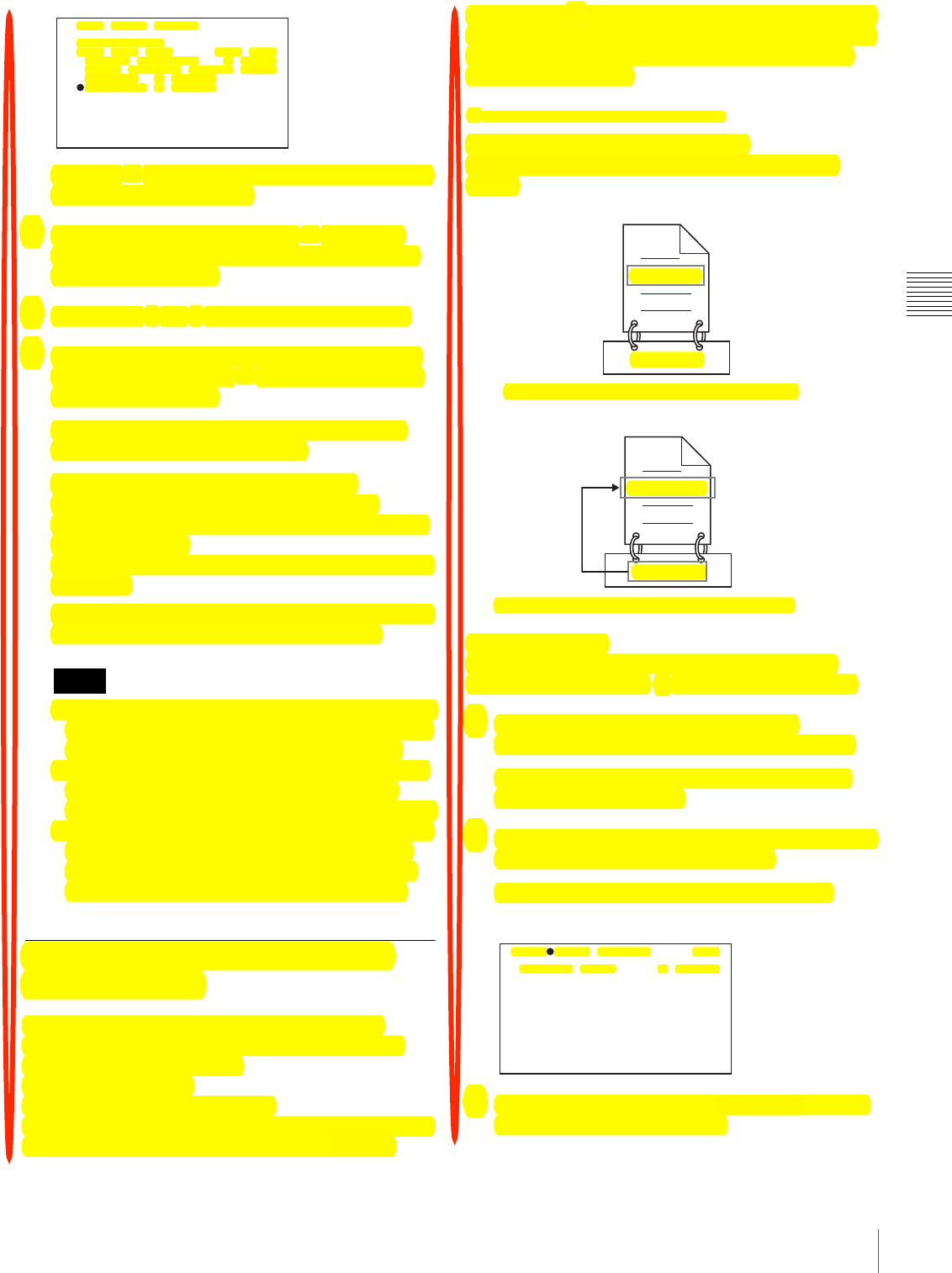
77
Recording – Advanced Operations
Chapter 3 Recording and Playback
2
Move the x mark to the digit you want to change and
then press the MENU knob.
3
Turn the MENU knob to move the x mark to the
desired digit in the list of selectable digits, and then
press the MENU knob.
4
Repeat steps 2 and 3 to enter the remaining digits.
5
When you have finished entering the value, turn the
MENU knob to move the x mark to END, and then
press the MENU knob.
The camcorder exits numeric input mode, and the
original CLIP TITLE page appears.
To check the titles of recorded clips
Press the THUMBNAIL button to display the
thumbnail screen, and then select the clip whose title
you want to check.
The title of the selected clip appears in the upper left of
the screen.
See “Cuing up with sub clip thumbnails” (page 86) for
more information about the thumbnail screen.
• It is not possible to specify 00000 as the initial value.
Even if you enter 00000, the value is reset to 00001
when the camcorder exits numeric input mode.
• The value of the serial number is incremented by 1
every time a title is generated. When the value
reaches 99999, the next number restarts from 00001.
• Duplicate clip titles can be generated if you reset the
serial number after recording several clips or the
same is true depending on the value setting. Care
should be taken when setting the serial number.
Assigning User-Defined Clip and
Clip List Names
The following standard format names are assigned
automatically to clips and clip lists that are created or
recorded by XDCAM devices.
Clips: C0001 to C0300
Clip lists: E0001E01 to E0099E01
You can use the supplied PDZ-1 Proxy Browsing Software
to assign user-defined names instead of the standard
format names 1). Assigning meaningful names to clips and
clip lists can facilitate file management. You can also use
this unit’s “AUTO TITLING” function to assign user-
defined names to clips.
1) 3/-'%-'%'0FF#1&(;%I1#.%I-1.$+1(%:(1'-#,%J<K<
To assign clip names on this unit
The title assigned to clip becomes its clip name (file
name).
Proceed as follows.
(How to select an item in the menu screen: Turn the
MENU knob to move the b mark to the desired item.)
1
Set TITLE in the CLIP TITLE page of the
OPERATION menu to “ENABLE” (see page 76).
For details on menu operations, see “Basic Menu
Operations” on page 131.
2
Display the FILE NAMING page of the OPERATION
menu, and then press the MENU knob.
The current setting parameters appear at the left of the
screen.
3
Turn the MENU knob to select “NAMING FORM”,
and then press the MENU knob.
Notes
0 05 CL IP T ITLE
0 12345 67 89
I NS DE L RE T E SC E ND
CLEAR N UM ERIC : EX EC
LOAD PR EF IX DA TA : EX EC
PREFI X : TITL E
NUMER IC : 0000 1
C0001.MXF
TITLE00001
When sub item “AUTO NAMING” is set to “C****”
TITLE00001.MXF
TITLE00001
When sub item “AUTO NAMING” is set to “TITLE”
TO P?0 06 FI LE N AMING
N AMING F OR M : C ** **
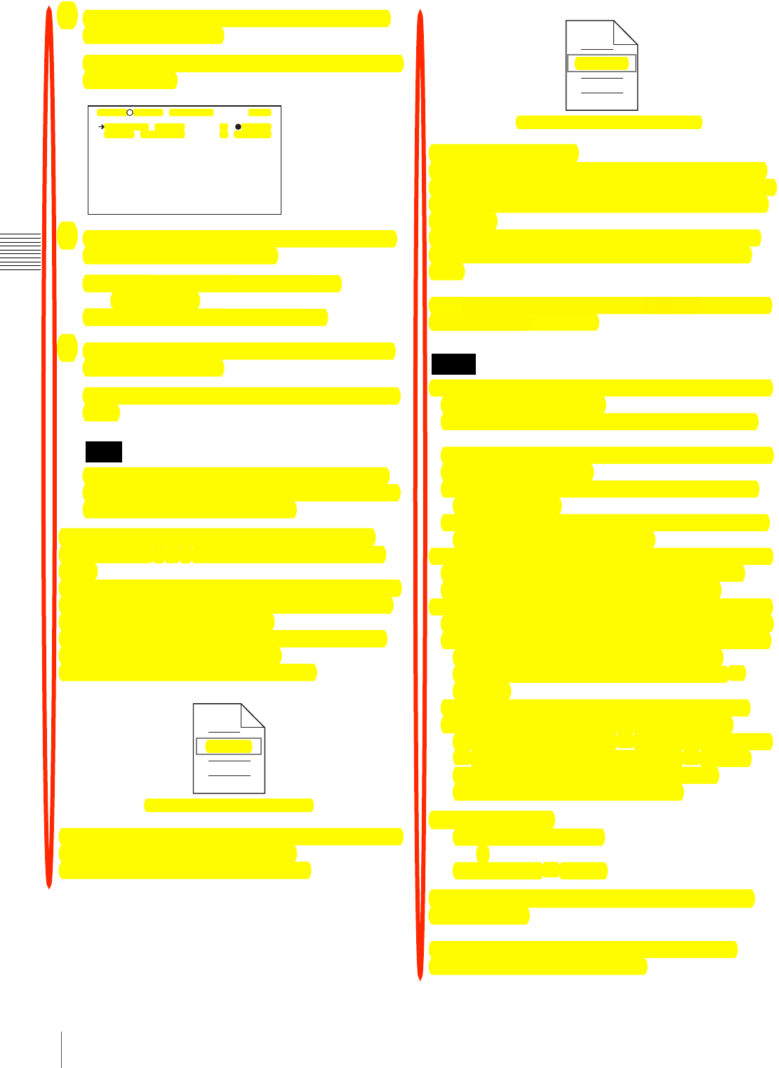
78 Recording – Advanced Operations
Chapter 3 Recording and Playback
4
Turn the MENU knob to display “FREE”, and then
press the MENU knob.
You are now able to use clips and clip lists with user-
defined names.
5
Turn the MENU knob to select “AUTO NAMING”,
and then press the MENU knob.
C****: Assign standard format clip names
automatically.
TITLE: Assign clip titles as clip names.
6
Turn the MENU knob to display “TITLE”, and then
press the MENU knob.
The same name will now be given to newly recorded
clips.
When the first letter of the title setting on the CLIP
TITLE menu is a space or period (.), the clip name is
the title string minus the first letter.
To enable clip and clip list renaming by FAM
Carry out steps 2 to 6 of “To assign clip names on this
unit”.
It is now possible to write, transfer, and rename clips and
clip lists with user-defined names over file access mode
(FAM) connections (see page 158).
To rename a clip, execute “Rename” on a clip with the
extension “.MXF” in the Clip folder.
The “.MXF” extension cannot be changed.
To rename a clip list, execute “Rename” on a clip list with
the extension “.SMI” in the Edit folder.
The “.SMI” extension cannot be changed.
To check clip names
Press the THUMBNAIL button to display the thumbnail
screen, and select the clip whose name you want to check.
The name of the selected clip appears at the upper left of
the screen.
However, when the clip has a title, the title is displayed
instead. Titles are enclosed in double quotation marks
(“ ”).
See “Thumbnail Search” (page 82) for more information
about the thumbnail screen.
• Items in the upper left of the screen are displayed in the
following order of priority.
Title > user-assigned clip name > standard clip name
Therefore, the display changes as follows, depending on
whether a clip has a title.
- The title is displayed for clips recorded on this unit
which have titles.
- The user-assigned or standard clip name is displayed
for clips which do not have titles.
• On XDCAM devices with firmware earlier than version
1.4, clips with user defined names are displayed as
“C5000” to “C9999” in the order of recording.
• Clip names and clip list names are converted as follows
for display in the thumbnail screen and the CLIP menu.
- If the clip name is longer than 15 characters, then the
first 9 characters and the last 5 characters are
displayed. Other characters are converted into s
symbols.
- Lowercase characters are converted to uppercase.
- Kanji and other multibyte characters and some
symbols are converted into s symbols. Sequences of
s symbols are converted into a single s symbol.
The following 21 symbols can be displayed.
: . ? ! # * / ( ) + - & @ = < > % " ; _ $
Display example:
JumpingDolphin_No103
r
JUMPINGDO s NO103
To check clip information (name, title, etc.) by
using a menu
See “Basic Menu Operations” (page 131) for more
information about menu operations.
Note
TO P?0 06 FI LE N AMING
N AMING F OR M : FR EE
A UTO N AM IN G : T IT LE
Fuji.MXF
Clip renaming by FAM is enabled
Notes
Sakura.SMI
Clip list renaming by FAM is enabled

79
Recording – Advanced Operations
Chapter 3 Recording and Playback
Display the CLIP STATUS page of the DIAGNOSIS
menu, and then press the MENU knob.
The current settings for each item are displayed on the
right side.
To create a list of title prefix strings
Prepare the data beforehand according to the following
rules.
File name
Assign the name “TITLES.TXT” to the file.
Input format
Enter title prefixes one at time, separated by newline
(CRLF) characters.
Prefixes can be up to 10 characters long. A prefix file can
contain up to 20 prefixes.
Allowable characters
• Digits: 0 to 9
• Alphabetic characters: a to z, A to Z
• The following symbols: ! , #, $, %, &, ', ( , ) , ~, =, -, ^,
@, [, ], {, }, +, ; (semicolon), , (comma), . (period), _
(underscore)
• Space
Title prefix list example
Tennis<CRLF>
Basketball<CRLF>
Skiing_1<CRLF>
Skiing_2<CRLF>
To transfer a title prefix list to the unit’s
internal memory
Proceed as follows.
1
Copy the title prefix file (TITLES.TXT) to the
following folder on the “Memory Stick”.
\\MSSONY\PRO\XDCAM\GENERAL\VAL_LIST
This folder is created when you insert a “Memory
Stick” into the camcorder. Do not create this folder
yourself on a computer.
2
Insert a “Memory Stick” with the title prefix file
(TITLES.TXT) into the “Memory Stick” slot of the
camcorder.
3
On the CLIP TITLE page, select LOAD PREFIX
DATA and then press the MENU knob.
“MEMORY STICK ACCESS” appears, and the file
on the “Memory Stick” (TITLES.TXT) is transferred
to the internal memory of the unit.
The message “COMPLETE!” appears when the
transfer finishes.
The message “FILE NOT FOUND!” appears if no list
of title prefixes is found.
Check the location where the file is stored on the
“Memory Stick”.
To select a prefix from the title prefix list
Proceed as follows.
1
On the CLIP TITLE page, select SELECT PREFIX
and then press the MENU knob.
A list of up to 20 title prefixes appears.
When no list of title prefixes has been transferred to
the internal memory of this unit, only the initial value
“TITLE” appears.
2
Select the desired title prefix from the list, and then
press the MENU knob.
The CLIP TITLE page appears again, and the selected
prefix appears in the PREFIX field.
Viewing Camera Video During
Playback (Live & Play Function)
By carrying out the following procedure before starting
playback, you can view camera video (live video) during
playback from the disc. This is a convenient way to frame
the next shot and adjust the exposure and focus while
viewing recorded video and playback video.
Note
TO P D 03 CL IP S TATUS
C LIP N O : 0 01 /0 10
N AME : C 00 01
T ITLE: ( no n am e)
R ECORD D EV ICE: PD W- F3 50
SE RI AL : 1 00 01
DA TE : 08 /0 1/ 06
TI ME : 15 :0 0: 05
Note
Note
F350
? P00 T IT LE PREF IX E SC
0 01: T en ni s
0 02: B as ke tball
0 03: S ki in g_1
0 04: S ki in g_2
0 05: A th le tics
0 06: A qu at ics
0 07: C yc li ng
0 08: S of tb all
0 09: F en ci ng
0 10: S ai li ng

80 Playback
Chapter 3 Recording and Playback
The FREEZE MIX function (see page 143) cannot be used
when the LIVE & PLAY function is on.
(How to select an item in the menu screen: Turn the
MENU knob to move the b mark to the desired item.)
1
Set LIVE & PLAY to ON on the OUTPUT page of the
OPERATION menu.
For details on menu operations, see “Basic Menu
Operations” on page 131.
2
Select the video signal output conditions from the
following modes.
OFF: Do not output camera video signals during disc
playback (output playback signals on the
viewfinder and LCD monitor, and from all video
connectors).
HDSDI: Select this mode when you want to switch the
output from the HDSDI OUT connector between
camera video and disc playback video (the output
from the VIDEO OUT connector and on the
viewfinder and LCD monitor is fixed as the
camera output).
VBS: Select this mode when you want to switch the
output from the VIDEO OUT connector between
camera video and disc playback video (the output
from the HDSDI connector is fixed as the camera
output).
When you select VBS, you will need an external
monitor with a HDSDI input connector to check the
camera video during playback.
On how to connect an external video monitor, see
“Connecting an External Video Monitor” on page 51.
Playback
Disc playback start position
Although this unit uses optical discs, it is designed to offer
the most convenient features of tape playback by VTRs.
One of these is the playback start position, which works in
the same way as with tape, as described below.
After playback stop
The unit stops at the position where the STOP button was
pressed.
Press the PLAY/PAUSE button to resume playback at the
stop position.
After recording
The unit stops at the position where recording ended.
To play back a clip, press the PREV button to move to the
start frame of any clip, or press the PREV button with the
PLAY/PAUSE button held down to move to any position.
After disc insertion
The unit stops at the position of the disc when it was most
recently ejected.
Press the PLAY/PAUSE button to resume playback at the
most recent position.
The playback position is saved to the disc when the disc is
ejected, which allows playback to start at that position
whenever it is loaded into any XDCAM player.
The playback position is not recorded to the disc if the disc
is set to REC INH.
Normal Playback
By pressing the PLAY/PAUSE button, you can review any
length of recording on the viewfinder screen in black and
white or in color on the LCD monitor. There are two other
ways to review the recording.
• Recording review: You can view the last two seconds of
the recording on the viewfinder screen in black and
white or in color on the LCD monitor.
• Using an external color video monitor: You can see the
recording in color on a color video monitor without the
need for any external adaptor.
You may also view the picture during a fast forward or fast
reverse search.
See “Side control panel (inside the protection cover)” on
page 20 for details about the switches and controls used to
select the audio output signal and to adjust the audio level.
Note
Note
Note

81
Playback
Chapter 3 Recording and Playback
Deteriorating playback conditions
Deteriorating playback may be due to the following
causes.
• Scratches and dust on the disc surface
This includes fingerprints, dust from the air, tar from
cigarette smoke, and so on.
Scratches and soiling which occur before recording are
not a problem because they are registered in advance as
defects, and recording avoids them. However, scratches
and soiling which occur after recording can lead to
deteriorating playback conditions.
• Aging of disc recording layers
Over several decades, the recording layers of optical
discs can age and cause deteriorating playback
conditions.
• Deteriorating laser diodes performance
The performance of the laser diodes used in optical
heads can worsen with age, leading to deteriorating
playback conditions.
Refer to the Maintenance Manual for an approximate
guide to when it is time to replace optical heads.
To prevent playback conditions from
deteriorating
Pay attention to the following points when handling discs.
• Do not open disc cartridges and touch discs directly with
your hands.
• Do not store for long periods in locations which are
dusty or exposed to air circulated by fans.
• Do not store for long periods under high temperatures or
in locations exposed to direct sunlight.
If playback conditions have deteriorated
Read errors occur when playback conditions continue to
deteriorate.
When a read error occurs, the message “DISC DEFECT”
appears, the video freezes, and the audio output is
suppressed.
If this happens, check the following points.
Whether the disc displays the same playback condition
on other XDCAM devices: If so, the surface of the
disc may be dirty or scratched, or the performance of
the recording layers on the disc may have worsened
due to age. Do not use discs with these symptoms.
Whether every disc inserted into an XDCAM device
displays the same playback conditions: If so, the
performance of the laser diodes may have
deteriorated. Check the total optical output time.
Freezing a Picture During Playback
Proceed as follows.
1
Press the PLAY/PAUSE button to start playback.
2
Press the PLAY/PAUSE button again at the instant
when you want to freeze the picture.
A frozen picture appears.
The time code is displayed in the time counter display
section and the PLAY/PAUSE indicator changes from
constant lighting to flashing (one flash/second).
3
To restart playback, press the PLAY/PAUSE button
once again.
When remotely controlling the camcorder from
an RM-B150/B750 Remote Control Unit
You can perform the same operation from the RM-B150/
B750.
Checking the Last Two Seconds of
the Recording (a Recording Review
Operation)
If you press the RET button on the lens while recording is
paused, the last two seconds of the recording is played
back on the viewfinder screen and the LCD monitor. Use
this function to check whether recording went smoothly. If
you hold down the RET button on the lens, playback
begins from the beginning of the clip. When you release
the RET button, the reverse search stops and playback in
the forward direction begins. After playback, the
camcorder is ready to start recording again.
By assigning the the same function as that of the RET
button on the lens to the ASSIGN 1/2/3/4 switch, you can
use the switch in the same way as the lens RET button.
Checking the Recording on a Color
Video Monitor
Connect a color video monitor to the VIDEO OUT or
HDSDI OUT connector of the camcorder. By pressing the
PLAY/PAUSE button, you can view the recorded picture.
On how to connect a color video monitor, see “Connecting
an External Video Monitor” on page 51.
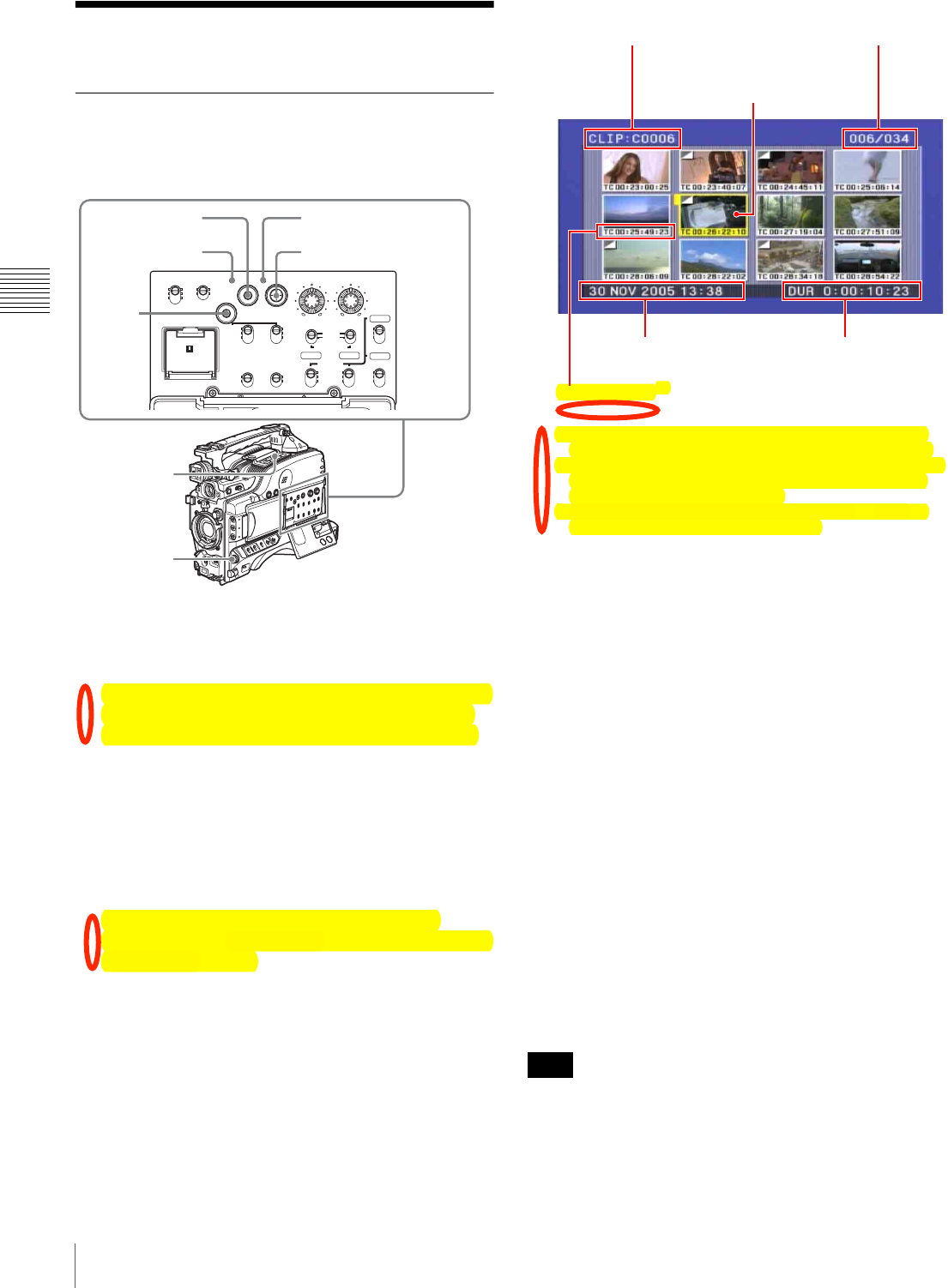
82 Thumbnail Search
Chapter 3 Recording and Playback
Thumbnail Search
Searching Using Thumbnails
To display the thumbnail images of all clips on the disc,
and cue up a desired clip, proceed as follows.
1
With the SUB CLIP indicator off, press the
THUMBNAIL button to turn the THUMBNAIL
indicator on.
If the SUB CLIP indicator is lit, you can turn it off by
pressing the SEL/SET button to the upper side (the
SUB CLIP side) with the SHIFT button held down.
If the menu screen is displayed, move the MENU
switch to the OFF position and press the
THUMBNAIL button.
If you set the MENU switch to ON while thumbnails
are displayed, thumbnail display is replaced with
menu display.
The thumbnails of all clips on the disc appear.
(In the following descriptions, this is referred to as the
“thumbnail screen”.)
a) When a title has been assigned to a clip (see page 75), the title is
enclosed in double quotation marks, for example “TITLE00001”.
b) A mark is shown to indicate that the thumbnail (index picture) is not
the first frame of the clip. (See “Changing the Thumbnail Image
(Index Frame) of a Clip” on page 83.)
c) You can select the information to be displayed (see page 83). The
factory default setting is display of timecode.
2
Use the SEL/SET button (four-way arrow key) or
MENU knob to select the desired clip.
You can also select clips by the following operations.
Press the PREV or NEXT button: Move to the
previous or next clip.
Press the PREV or NEXT button with the F REV
or F FWD button held down: Move to the first
or last clip.
Press the F REV/F FWD button: Move to the
previous or next page.
3
To cue up the selected clip, press the SEL/SET button
or the MENU knob.
To start playback from the selected clip, press the
PLAY/PAUSE button.
The remainder of the thumbnail selection process is the
same as in steps 2 and 3 above.
To return to the previous screen
Press the THUMBNAIL button, turning the
THUMBNAIL indicator off. At any point in the procedure
you can return to the previous screen with this operation.
The factory default setting is to use the first frame of a clip
as its thumbnail image. At recording time, you can change
this to another frame within 10 frames of the start of the
clip (page 70). You can also change it to any frame at
playback time (page 83). However, the thumbnail search
CH-1
MIX
CH-2
CH-3
PRESET
AUTO
FRONT
WIRELESS
REAR
CH-1
MANUAL
AUDIO SELECT
AUDIO IN
F-RUN
REGEN
ON
OFF
SET
ON
OFF
CLOCK
F
W
R
F
W
R
R-RUN
MONITOR
FRONT MIC
LOW CUT VIDEO OUT
CHARACTER
AUDIO LEVEL
THUMBNAIL SUB CLIP
MIX
CH-4
CH-1/2
CH-3/4
SHIFT CLIP MENU
SEL/SET 0 10 0 10
ESSENCE
MARK
CH-2
CH-3
CH-4
LITHIUM BATT
2,3
1
3
2
THUMBNAIL
indicator
SUB CLIP indicator
SHIFT
button
Note
Sixth clip is selected
from a total of 34 clips.
Recording date and time
of selected clip Duration of selected clip
Name of currently
selected clip a)
Thumbnail of currently
selected clip (first frame
or specified b) frame)
Clip information C)
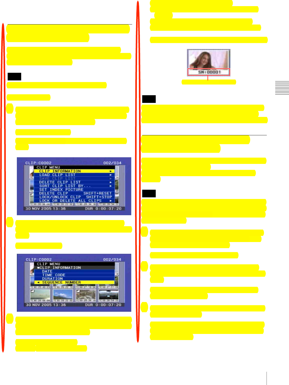
83
Thumbnail Search
Chapter 3 Recording and Playback
function always cues up the first frame in a clip, even if the
thumbnail image has been changed.
To switch the information displayed
in the thumbnail screen
You can switch the clip information displayed at the
bottom of thumbnails. You can also switch the display of
thumbnail sequence numbers.
The factory default setting is “TIME CODE”.
Proceed as follows.
1
With the thumbnail screen displayed, hold down the
SHIFT button and press the SEL/SET button to the
bottom side (the CLIP MENU side).
The CLIP menu appears.
See page 100 for more information about the CLIP
menu.
2
Use the SEL/SET button or MENU knob to select
“CLIP INFORMATION”, and then press the button or
knob.
A sub menu appears.
3
Use the SEL/SET button or the MENU knob to select
the information to display from among the following,
and then press the button or knob.
•DATE: Date of recording
•TIME CODE: Start timecode
•DURATION: Whole length of clip
•SEQUENCE NUMBER: Thumbnail sequence
number
The information displayed on the lower side of
thumbnails changes according to the item selected.
Example: When “SEQUENCE NUMBER” is selected
Some characters in clip names, clip list names, and titles
may be converted to “s” characters for display in the
thumbnail screen and CLIP menu. For details, see page 78.
Changing the Thumbnail Image
(Index Frame) of a Clip
In the thumbnail screen, normally the first frame of a clip
is displayed as the index frame.
To change this to show a different frame, proceed as
follows.
You can also select (at 1-second intervals) a frame within
10 seconds of the first frame as the thumbnail image of the
clip at the time when you record a clip with this unit. For
details, see page 70.
1
With the thumbnail screen displayed, hold down the
SHIFT button and press the SEL/SET button to the
bottom side (the CLIP MENU side).
The CLIP menu appears (see page 100).
2
Use the SEL/SET button or MENU knob to select
“SET INDEX PICTURE”, and then press the button/
konb.
This switches to the screen for selecting a clip for
changing the index frame.
3
Select the desired thumbnail, and press the SEL/SET
button or MENU knob.
The frame from the clip that is currently specified as
the thumbnail is displayed. In this state, you can use
playback or search.
Note
Note
Note
Thumbnail sequence number
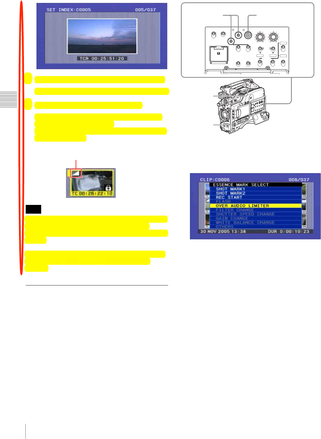
84 Thumbnail Search
Chapter 3 Recording and Playback
4
Using playback or search, find the new index frame.
You can also turn the MENU knob for a jog operation.
5
Press the SEL/SET button or MENU knob.
This sets the selected scene as the index frame, and
returns to the thumbnail screen.
When the thumbnail is other than the first frame, this
is shown as follows.
If you select a marked thumbnail, and press the SEL/SET
button or MENU knob, this does not cue up to the
thumbnail position. Cuing up is always to the first frame of
the clip.
To cancel setting the index frame, hold down the SHIFT
button and press the SEL/SET button down (CLIP
MENU).
Cuing Up a Frame by Searching for
an Essence Mark
Proceed as follows.
1
With the SUB CLIP indicator off, hold down the
SHIFT button and press the THUMBNAIL button.
The essence mark selection screen appears.
Essence marks not recorded on the disc appear in gray.
To escape from the essence mark selection screen to
the previous screen
Press the RESET button on the right side of the LCD
monitor.
2
Use the SEL/SET button or the MENU knob to select
the desired essence mark.
3
Press the SEL/SET button or the MENU knob.
Thumbnails of the frames including the selected
essence mark appear.
Note
Mark indicating that the
thumbnail is not the first frame
CH-1
MIX
CH-2
CH-3
PRESET
AUTO
FRONT
WIRELESS
REAR
CH-1
MANUAL
AUDIO SELECT
AUDIO IN
F-RUN
REGEN
ON
OFF
SET
ON
OFF
CLOCK
F
W
R
F
W
R
R-RUN
MONITOR
FRONT MIC
LOW CUT VIDEO OUT
CHARACTER
AUDIO LEVEL
THUMBNAIL SUB CLIP
MIX
CH-4
CH-1/2
CH-3/4
SHIFT CLIP MENU
SEL/SET 0 10 0 10
ESSENCE
MARK
CH-2
CH-3
CH-4
LITHIUM BATT
2-5
1
5
2-5

85
Thumbnail Search
Chapter 3 Recording and Playback
(The example shows the case where SHOT MARK1 is
selected as the essence mark.)
Searching Using the Chapter
Function
A thumbnail display shows the SHOT MARK 1 and
SHOT MARK 2 recorded within the specified clip as
chapter titles.
1
With the THUMBNAIL indicator and SUB CLIP
indicator off, press the THUMBNAIL button.
2
Use the SEL/SET button (four-way arrow key) or
MENU knob to select the desired clip.
An “S” mark appears at the upper right of the
thumbnails of clips that have short marks set.
3
Press the COUNTER/CHAPTER button on the right
side of the LCD monitor.
A chapter screen is displayed.
The essence marks (REC START, SHOT MARK 1,
SHOT MARK 2) recorded within the clip appear as
thumbnails.
The “S1” and “S2” marks displayed on thumbnails
indicate frames where SHOT MARK1 and SHOT
MARK2 are set.
Thumbnails without one of these marks are frames
where REC START essence marks are set.
For details of chapter settings, see “Recording Shot
Marks” (page 70).
Deleting shot marks
You can delete a specified clip shot mark.
• Only SHOT MARK 1 and SHOT MARK 2 can be
deleted. REC START cannot be deleted.
• Shot mark deletion is only possible when the settings are
such that shot mark recording is possible.
• Essence marks cannot be deleted when the clip is locked
(page 87).
1
In the chapter screen, hold down the SHIFT button and
press the SEL/SET button down (CLIP MENU).
The CLIP menu appears (see page 100).
2
Select DELETE SHOT MARK.
3
Select the clip (SHOT MARK 1 or SHOT MARK 2).
By holding down the SHIFT button and turning the
MENU knob, you can select more than one chapter.
4
Press the SEL/SET button or MENU knob.
A confirmation message appears.
5
Select “OK” and then press the SEL/SET button or
MENU knob.
This deletes the specified shot mark.
Searching Using the Expand
Function
Using the expand function, you can divide the duration of
a selected clip on the thumbnail screen into 12 segments,
Sixth frame is selected
from a total of 36 SHOT
MARK 1.
Recording date and time of the clip
that contains the selected frame
Currently selected
SHOT MARK 1 frame
This indicates that the thumbnail
images are the frames including the
essence mark (SHOT MARK 1).
Frame information (date and time of
creation, timecode, recording time)
Time from the
selected short mark to
the next shot mark
“S” mark
Notes
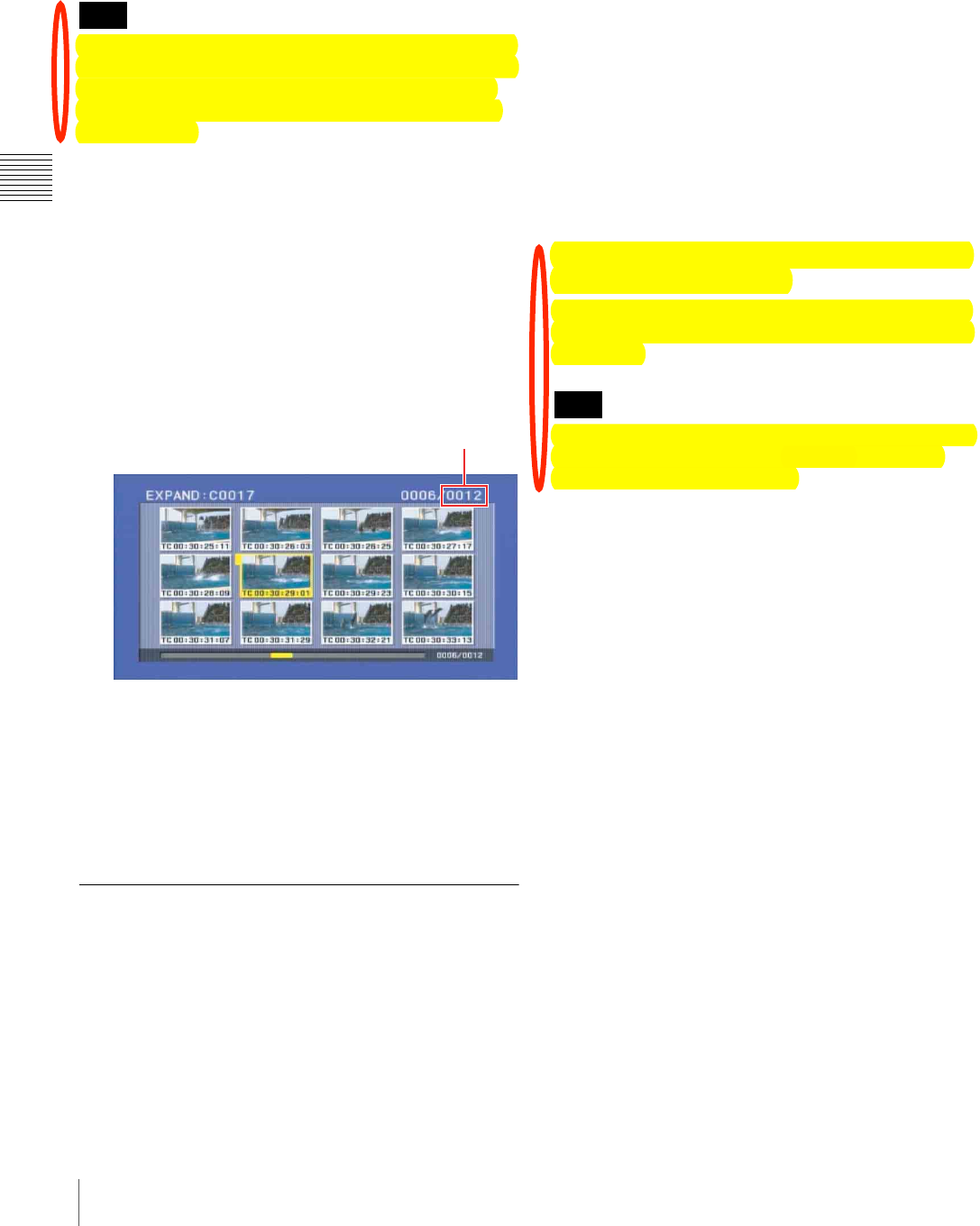
86 Thumbnail Search
Chapter 3 Recording and Playback
and display a new thumbnail screen showing the first
frame in each segment. This function allows rapid
searching of the scenes within a particular clip. The expand
function can be applied up to three times (12 divisions, 144
divisions, and 1728 divisions).
The maximum number of blocks may be larger than 1728
when the recorded duration of the clip is short. In this case,
the frame interval of expanded thumbnails is fixed at 1
frame. This allows you to view expanded thumbnails at
equal intervals.
1
With the THUMBNAIL indicator and SUB CLIP
indicator off, press the THUMBNAIL button.
2
Use the SEL/SET button (four-way arrow key) or
MENU knob to select the desired clip.
3
Press the DISPLAY/EXPAND button on the right side
of the LCD monitor.
Thumbnails appear for twelve equal divisions of the
clip.
To change the expansion ratio
Each time you press the DISPLAY/EXPAND button
changes the ratio in the sequence ×12 $%×144 $ ×1728.
To change the ratio in the reverse sequence, hold down the
SHIFT button and press the DISPLAY/EXPAND button.
Alternatively, press the RESET button on the right side of
the LCD monitor to return to the previous screen.
Clip List Playback
You can play back clips in their order in a clip list created
with the scene selection function (see Chapter 4).
Playing back in clip list order
Proceed as follows.
1
If the clip list that you want to play exists on the disc,
load it into the current clip list (see page 92).
For the clip list loading operation, see “Loading a
Clip List From the Disc as the Current Clip List” on
page 101.
2
With the THUMBNAIL indicator off, hold down the
SHIFT button and press the SEL/SET button up (SUB
CLIP).
The SUB CLIP indicator lights.
3
Press the PLAY/PAUSE button.
Playback begins from the first sub clip in the current
clip list.
To return from clip list playback mode to
normal playback mode
With Clip list playback stopped, hold down the SHIFT
button and press the SET/SEL to the top side (the SUB
CLIP side).
Depending on the length of sub clips in the clip list and
their arrangement on the disc, playback may freeze
momentarily between sub clips.
Cuing up with sub clip thumbnails
With the desired clip list loaded in the current clip list,
proceed as follows.
1
Press the THUMBNAIL button, lighting the
THUMBNAIL indicator.
2
Hold down the SHIFT button, and press the SEL/SET
button up (SUB CLIP).
The clip list display appears.
See page 93 for more information about the clip list
screen.
Note
Displays the number
of clip divisions
Note
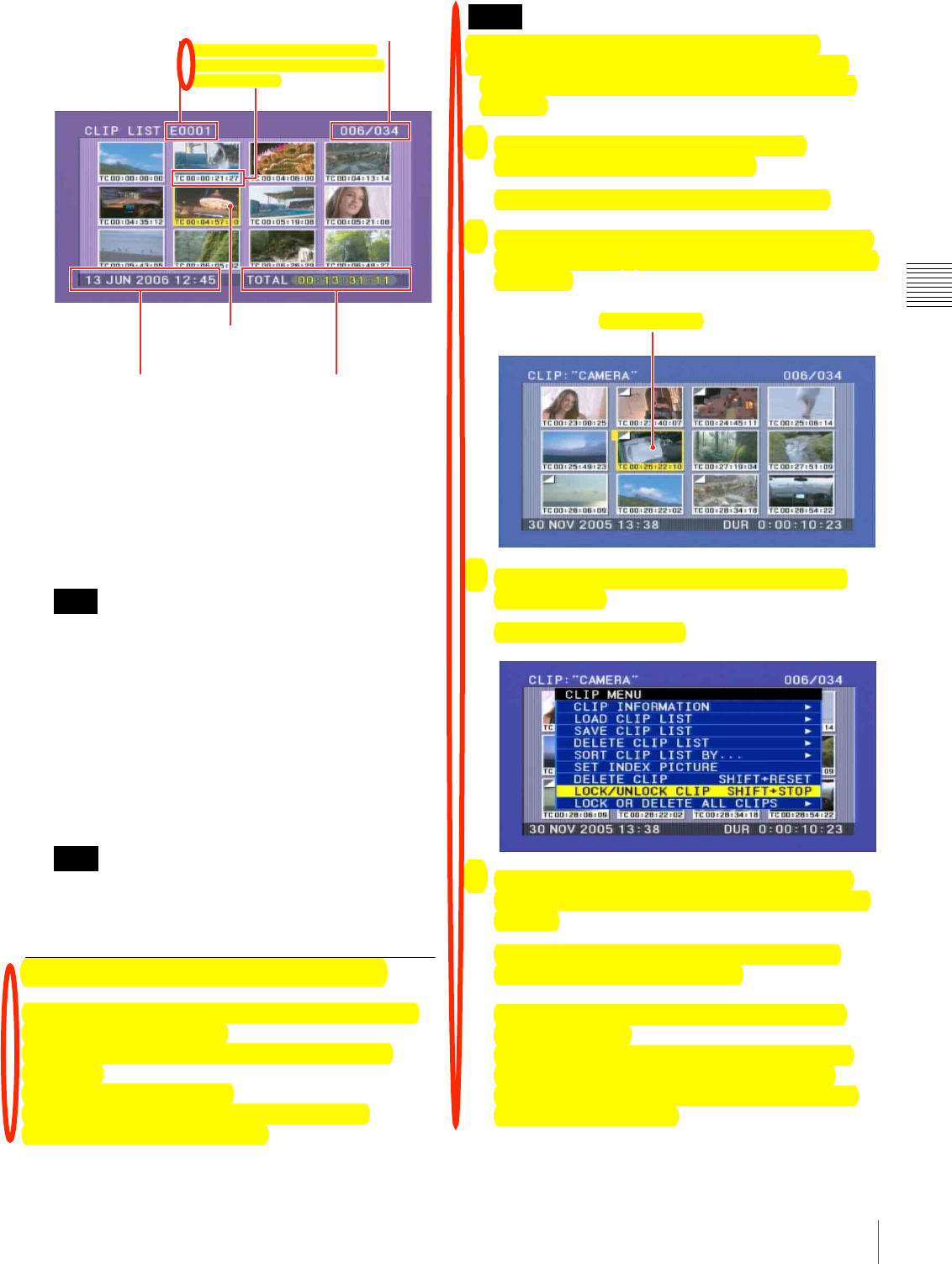
87
Thumbnail Search
Chapter 3 Recording and Playback
a) If the clip list has a title (page 75), the title is displayed enclosed in
double quotation marks, for example “TITLE00001”.
To escape from the clip list display to the whole-
screen display
Press the THUMBNAIL button to turn the
THUMBNAIL indicator off.
This returns to the clip list playback state.
Stop the unit before using the SUB CLIP button. Press
the STOP button if the message “STOP ONCE!”
appears.
3
Use the SEL/SET button or MENU knob to select the
sub clip you want to cue up.
4
To cue up the selected clip, press the SEL/SET button
or MENU knob. To start playback from the selected
clip, press the PLAY/PAUSE button.
The clip list thumbnail screen always shows the first
frame (In point) of each sub clip.
Locking (Write-protecting) Clips
In the thumbnail screen, you can lock them so that they
cannot be deleted or altered.
Locking prevents the following operations on clips.
• Deletion
• Renaming by FAM or FTP
• Changing the thumbnail image (index picture)
• Adding and deleting shot marks
• Locked clips are deleted along with other clips.
• Clips cannot be locked or unlocked when the Write
Inhibit tab of the disc is set to the recording disabled
position.
1
With the SUB CLIP indicator off, press the
THUMBNAIL button, turning it on.
The thumbnails of the clips on the disc appear.
2
Select the clip to lock (you can do this with the same
operations as step 2 of “Searching Using Thumbnails”
(page 82).
3
Hold down the SHIFT button and press the CLIP
MENU button.
Then CLIP menu appears.
4
Use the SEL/SET button or MENU knob to select
“LOCK/UNLOCK CLIP”, and then press the button
or knob.
A lock confirmation screen appears. This screen
displays clip names and clip titles.
To cancel the lock operation and return to the
thumbnail screen
Use the SEL/SET button or MENU knob to select
“CANCEL”, and then press the button or knob.
Alternatively, press the RESET button on the right
side of the LCD monitor.
Note
Note
Sixth frame is selected
from a total of 34 sub clips.
Recording date and time
of selected sub clip
!"#$%&'($')*+,-./'+)$01./2$.)1$
/'-2$+*$%,2./'+)3$')'/'.&$/'-2%+123$
(&.4#.%5$/'-26
Name of loaded clip list a)
Total playback time of
sub clips in a clip list
Currently selected
sub clip
Notes
Clip to be locked
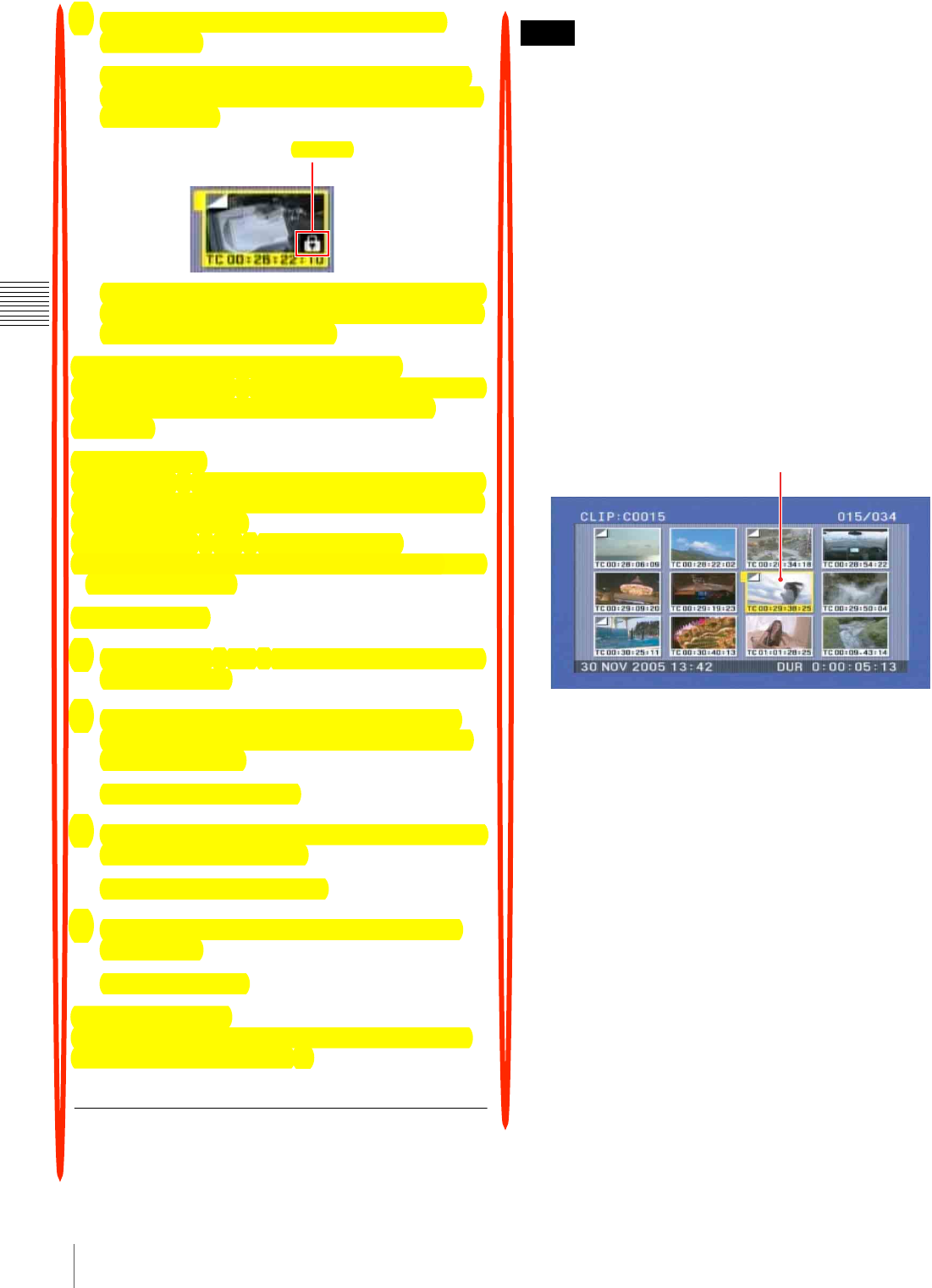
88 Thumbnail Search
Chapter 3 Recording and Playback
5
With OK selected, press the SEL/SET button or
MENU knob.
You return to the thumbnail screen, and a lock icon
appears on the thumbnail of the selected clip to show
that it is locked.
You cannot delete locked clips, rename them, set their
thumbnails, and so on. Unlock the clip if you want to
perform any of these operations.
To lock clips with a shortcut operation
After carrying out step 2 in the procedure, press the STOP
button with the SHIFT button held down (shortcut
operation).
To unlock clips
Carry out step 2 of “Locking clips” to select a locked clip
(one with the lock icon displayed on its thumbnail). Then
do one of the following.
• Carry out steps 3 and 4 of “Locking Clips.”
• Press the STOP button with the SHIFT button held down
(shortcut operation).
To lock all clips
1
Carry out steps 1 and 3 of “Locking Clips” to display
the CLIP MENU.
2
Use the SEL/SET button or MENU knob to select
“LOCK OR DELETE ALL CLIPS”, and then press
the button. or knob.
A submenu screen appears.
3
Select “LOCK ALL CLIPS”, and then press the SEL/
SET button or MENU knob.
A confirmation screen appears.
4
With “OK” selected, press the SEL/SET button or
MENU knob.
All clips are locked.
To unlock all clips
Carry out the procedure in “To lock all clips”, selecting
UNLOCK ALL CLIPS in step 2.
Deleting Clips
You can delete clips while checking their contents.
• Clips cannot be deleted when the Write Inhibit tab of the
disc is set to the recording disabled position.
• If the deletion target clip is referenced by clip lists on the
disc, all of those clip lists are deleted as well.
• If the deletion target clip is referenced in the current clip
list, all of the referenced sub clips, and only those sub
clips, are deleted at the same time as the deletion target
clip.
• You can use the DISC MENU to delete the last clip or all
clips. For details, see page 69.
1
With the SUB CLIP indicator off, press the
THUMBNAIL button, turning it on.
The thumbnails of the clips on the disc appear.
2
Select the clip to delete (you can do this with the same
operations as step 2 of “Searching Using Thumbnails”
(page 82).
3
Press the CLIP MENU button with the SHIFT button
held down.
The CLIP menu appears (see page 100).
4
Use the SEL/SET button or MENU knob to select
“DELETE CLIP”, and then press the button. or knob.
A deletion confirmation screen appears and then
thumbnails of four frames (the first frame,
intermediate frame 1, intermediate frame 2, and the
last frame) in the target clip appear. At the same time,
the clip name, title, date and time of creation, and
duration appear.
One of the following messages appears, depending on
whether the target clip is referenced in a clip list.
• When the target clip is not referenced in a clip list:
“DELETE CLIP?”
• When the target clip is referenced in a clip list:
“DELETE CLIP & CLIP LIST?” (All clip lists that
reference the deletion target clip will be deleted as
well).
Lock icon
Notes
Clip to be deleted

89
Thumbnail Search
Chapter 3 Recording and Playback
To cancel the deletion and return to the thumbnail
screen
Use the SEL/SET button or MENU knob to select
“CANCEL”, and then press the button or knob.
Alternatively, press the RESET button on the right
side of the LCD monitor.
5
Use the SEL/SET button or MENU knob to select
“OK”, and then press the button or knob.
The clip is deleted and you return to the thumbnail
screen.
To delete clips with a simple operation
You can delete clips without displaying the CLIP menu.
After step 2, press the RESET button on the right side of
the LCD monitor with the SHIFT button held down
(shortcut operation).
The clip deletion screen appears directly, without
displaying the CLIP MENU.
To delete all clips
1
Carry out steps 1 and 3 of “Locking Clips” to display
the CLIP MENU.
2
Use the SEL/SET button or MENU knob to select
“LOCK OR DELETE ALL CLIPS”, and then press
the button or knob.
A sub menu appears.
3
Use the SEL/SET button or MENU knob to select
“DELETE ALL CLIPS”, and then press the button or
knob.
A deletion confirmation screen appears.
4
To execute the deletion, use the SEL/SET button or
MENU knob to select “OK”, and then press the button
or knob.
All clips are deleted.
• Locked clips cannot be deleted.
• When all clips have been deleted, you return to the
normal screen.
Notes

Chapter4
90 Overview
Chapter 4 Scene Selection
Scene Selection
Overview
What is scene selection?
Scene selection is a function which allows you to select
material (clips) from the material recorded on a disc and
perform cut editing. You can do this by operating on this
unit only.
• Scene selection is a convenient way to perform cut
editing in the field and in other offline situations.
• In scene selection you create a clip list (editing data).
Since the material itself is not affected, you can repeat
this any number of times.
• You can play back the edit list created by scene selection
on this unit.
• In the scene selection function, you can add whole clips,
add parts of a clip, add using chapters, change the
playback sequence, amend or delete In and Out points,
and carry out all of these operations simply on this unit.
• Clip lists (edit data) created with the scene selection
function can be used on XPRI and other full-feature
nonlinear editing systems.
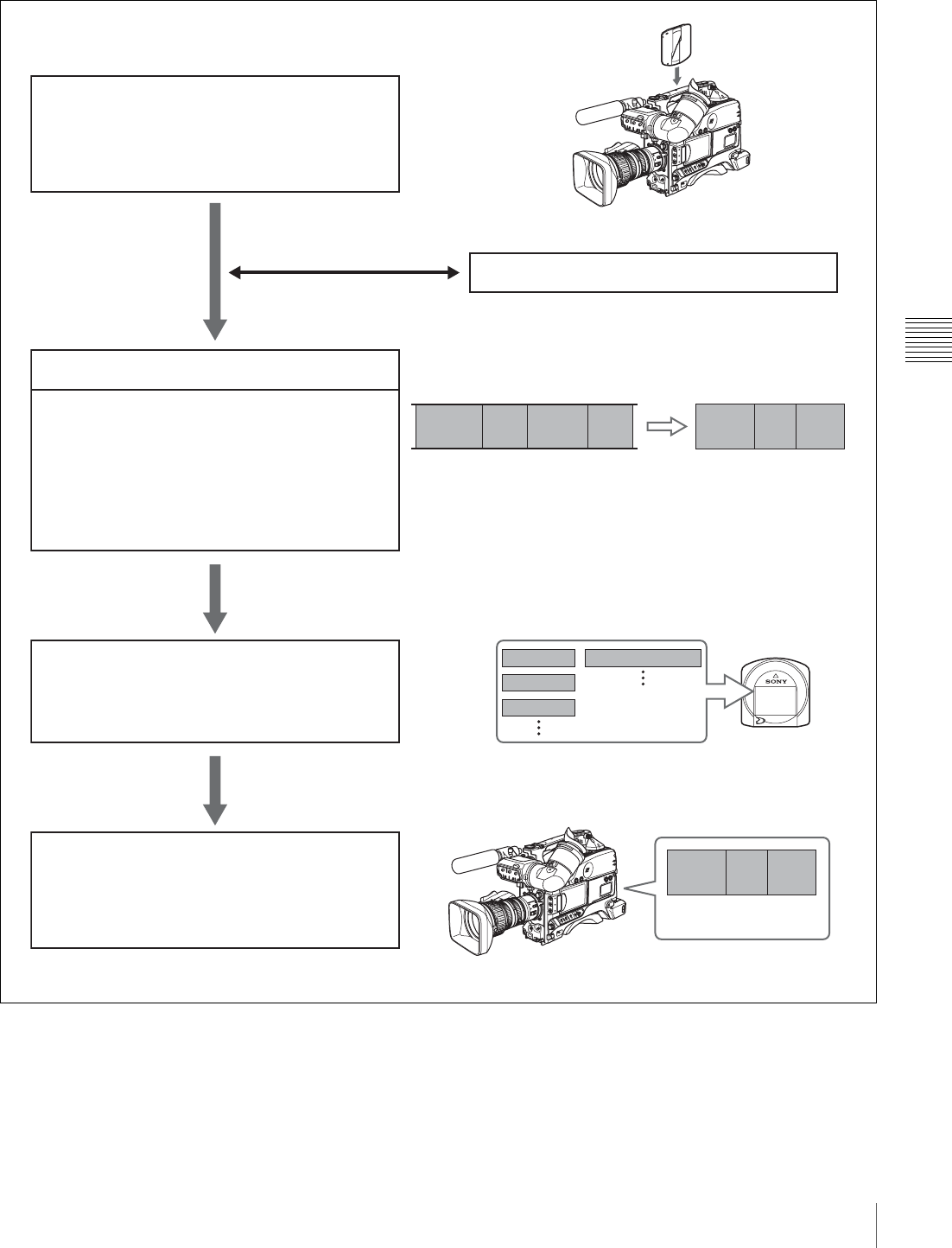
91
Overview
Chapter 4 Scene Selection
Flow of scene selection editing
Record material or insert disc containing recorded
material into this unit
PDW-F330/F330P/F350/F350P
To edit a clip list on the disc
Load clip lists (see page 101)
• Including sub clips in the current clip list !"##$%&'# ?@*
• Reordering sub clips !"##$%&'# ?A*
• Adjusting the sub clip In/Out points (trimming)
!"##$%&'# ?A*
• Deleting sub clips !"##$%&'# ?B*
Create and edit a clip list
Save the clip list to disc (see page 98)
Select clipsRecorded material Clip list 1
Clip 1 Clip 2 Clip 3 Clip 4
Sub clip 1
Sub clip 2
Sub clip 3
Disc
Disc
Clip 1
Clip 2
Clip 3
Clip list 1
Play back the clip list (see page 86)
Sub clip 1
Sub clip 2 Sub clip 3
Play back clip list
PDW-F330/F330P/F350/F350P
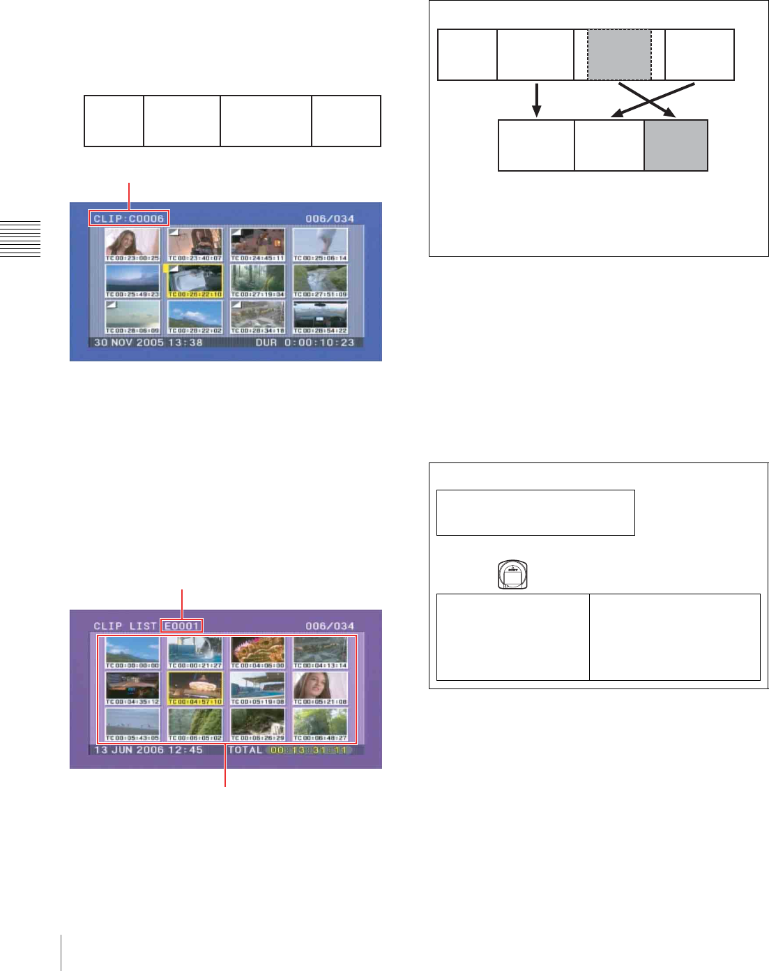
92 Overview
Chapter 4 Scene Selection
Clip
Material recorded with this unit is managed in units called
“clips”. A clip contains the material between a recording
start point and a recording end point.
Clips have numbers beginning with C, for example C0001.
Instead of using clip numbers, you can manage clips by
assigning clip titles or names. !"#$%&'()*+,$+&&$-(.&+$/0$
(1%$//2
Clip list
You can use the scene selection function to select desired
clips from the clips saved on a disc and create a cut edit list
called a “clip list”.
Clip lists have numbers beginning with E, for example
E0001. Up to 99 clip lists can be saved on a disc.
Sub clips (clips in clip lists)
The specified clips (or parts of clips) in a clip list are called
“sub clips”. Sub clips are virtual edit lists specifying
ranges in the original clips. Clip data in the original clips is
not overwritten.
The following figure illustrates the relation between clips
and sub clips.
Clip list editing (current clip list)
To edit a clip list, you need to load the clip list from the
disc into the internal unit memory.
The clip list which is currently loaded into the unit memory
is called the “current clip list”.
The current clip list is always the target of sub clip creation
and editing. Clip list playback also uses the current clip
list.
After creating and editing a clip list, you need to save it to
disc.
Clip list playback
Clips and clip lists are saved together on a disc.
Clips are played back according to clip list data.
Recording
start point of
clip 2 Recording end
point of clip 2
r r
Clip 1
(C0001) Clip 2
(C0002) Clip 3
(C0003) Clip 4
(C0004)
Clip number
Clip list number
Thumbnails of selected clip list
Unit memory
Current clip list
Can be edited (adding, deleting, and
reordering sub clips) t
Clip list playback
and thumbnail
display
SAVE Mm LOAD
Disc
C0001 (Clip 1)
C0002 (Clip 2)
C0003 (Clip 3)
•
•
•
E0001 (Clip list 1)
E0002 (Clip list 2)
E0003 (Clip list 3)
•
•
•
E0099 (Clip list 99)
Clip 1
(C0001) Clip 2
(C0002) Clip 3
(C0003) Clip 4
(C0004)
Sub clip 1 Sub clip 2 Sub clip 3
Clip list (E0001)
Clips on the disc
In the above example, the whole of clip 2 has been added as sub
clip 1, and the whole of clip 4 has been added as sub clip 2. Sub
clip 3 is part of clip 3. Therefore, when clip list E0001 is played
back, clip 4 is played after clip 2, and then the part of clip 3 shown
in gray color is played.
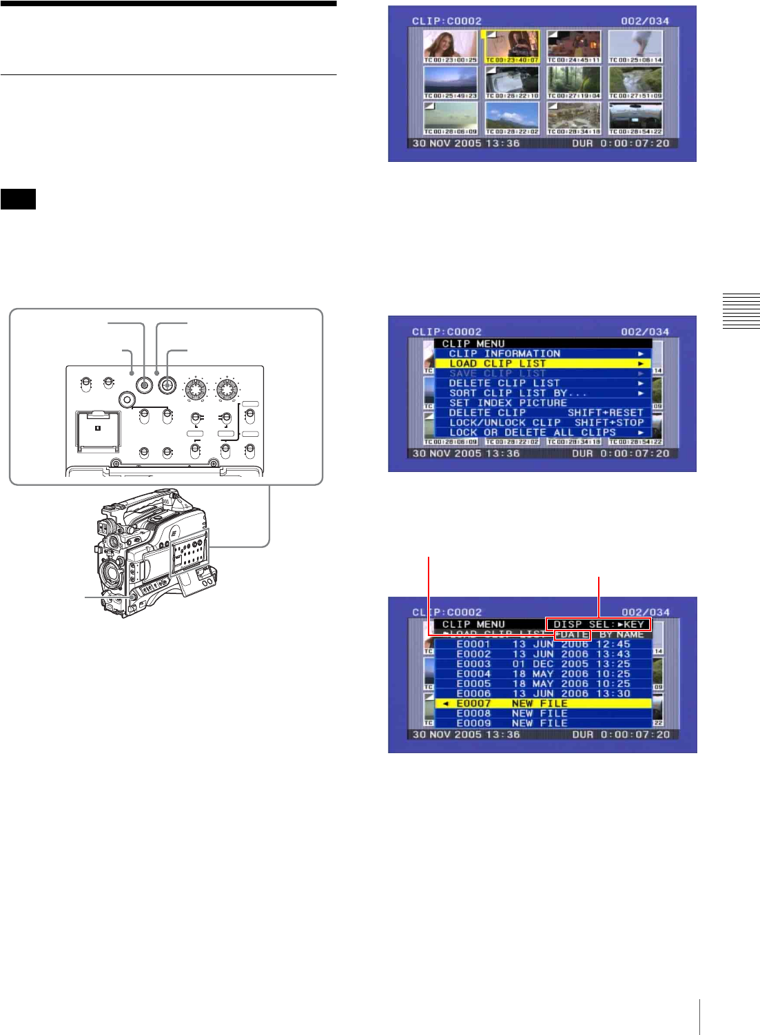
93
Creating Clip Lists
Chapter 4 Scene Selection
Creating Clip Lists
Including Sub Clips in the Current
Clip List
Select the desired clip in the thumbnail screen, to include
it in the clip list as a sub clip.
The CLIP menu handles up to 99 clip lists.
Including a clip selected in the thumbnail
screen in the clip list
Proceed as follows.
1
With the SUB CLIP indicator off, press the
THUMBNAIL button to turn the THUMBNAIL
indicator on.
If the menu screen is displayed, move the MENU
switch to the OFF position and press the
THUMBNAIL button.
If you move the MENU switch to ON while
thumbnails are displayed, the thumbnail display
disappears, and the menu appears.
The thumbnails of the clips on the disc appear.
(In the following description, this is referred to as the
“thumbnail screen”. )
2
Hold down the SHIFT button, and press the SEL/SET
button up (SUB CLIP).
The “LOAD CLIP LIST” screen of the CLIP menu
appears.
For an already created clip list, the details including
the creation date appear, and for an empty clip list,
“NEW FILE” appears.
(If a clip list is already loaded, the LOAD CLIP LIST
screen does not appear. In this case proceed to step 4.)
To switch the information displayed in clip
lists
Press the SEL/SET button to the right side.
Each press of the button switches the information
displayed in the following order.
Date and time of creation t title t clip name t ....
The following information is displayed for each type.
+DATE: Date and time of clip list creation or last
modification
+TITLE: The title of the clip list, if it has one
Note
CH-1
MIX
CH-2
CH-3
PRESET
AUTO
FRONT
WIRELESS
REAR
CH-1
MANUAL
AUDIO SELECT
AUDIO IN
F-RUN
REGEN
ON
OFF
SET
ON
OFF
CLOCK
F
W
R
F
W
R
R-RUN
MONITOR
FRONT MIC
LOW CUT VIDEO OUT
CHARACTER
AUDIO LEVEL
THUMBNAIL SUB CLIP
MIX
CH-4
CH-1/2
CH-3/4
SHIFT CLIP MENU
SEL/SET 0 10 0 10
ESSENCE
MARK
CH-2
CH-3
CH-4
LITHIUM BATT
2-9
1
3,5-8
SUB CLIP indicator
THUMBNAIL indicator
Displays the type of
the information Switch the displayed information
by pressing the SEL/SET button
to the right side
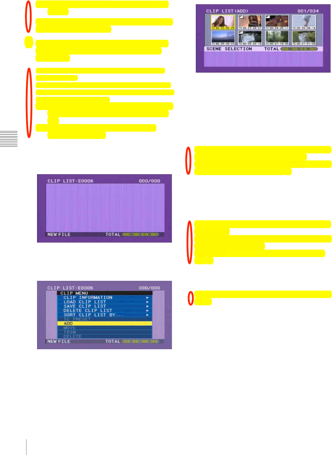
94 Creating Clip Lists
Chapter 4 Scene Selection
+NAME: The standard or user-defined name of the
clip list
You can also use the supplied PDZ-1 Proxy Browsing
Software to set clip list titles.
3
Use the SEL/SET button or MENU knob to select a
clip list number (E0001 and so on), and press the
button/knob.
L#0%*+,%+)'#%.#:(%&/(%*01'#1%$-&/%&/(%BM5N%+,;%
65A3%90&&#,'<%
O/(,%P#0%/+:(%+%)+1G(%,0.9(1%#I%*)-F%)-'&'E%P#0%*+,%
0'(%&/(%I#))#$-,G%#F(1+&-#,'%&#%.#:(%&/(%*01'#1%*)#'(1%
&#%&/(%*)-F%)-'&%&/+&%P#0%$+,&<
With the SHIFT button held down, press the PREV
or NEXT button: Move to the first or last clip
list.
Press the F REV or F FWD button: Move to
previous or next page.
If you select a clip list number with a NEW FILE flag,
an empty clip list is displayed as shown in the
following figure.
4
Hold down the SHIFT button, and press the SEL/SET
button down (CLIP MENU).
The CLIP menu appears.
5
Use the SEL/SET button or MENU knob to select
“ADD”, then press the button/knob.
A screen as shown below appears.
(In the following description, this whole screen is
referred to as the “scene selection screen”.)
To return to the CLIP menu
Press the RESET button on the right side of the LCD
monitor.
6
Use the SEL/SET button (four-way arrow key) or
MENU knob to select the clip you want to include in
the clip list, press the button/knob.
To make a multiple selection, hold down the SHIFT
button, and turn the MENU knob.
An I-bar cursor appears in a window in the lower part
of the screen to show the insertion position.
If you press the RESET button at this point, you return
to the state at the beginning of step 6.
7
Press the SEL/SET button or MENU knob.
The clip selected in the upper part is added to the
current clip list in the lower part, as a sub clip.
The screen returns to the CLIP menu (see step 4).
To continue working without returning to the
CLIP menu
With the SHIFT button held down, press the SEL/SET
button or the MENU knob.
You return directly to the scene selection screen of
step 5.
8
Repeat steps 5 to 7 until all desired clips have been
added to the current clip list.
You can add the same clip as a sub clip any number of
times.
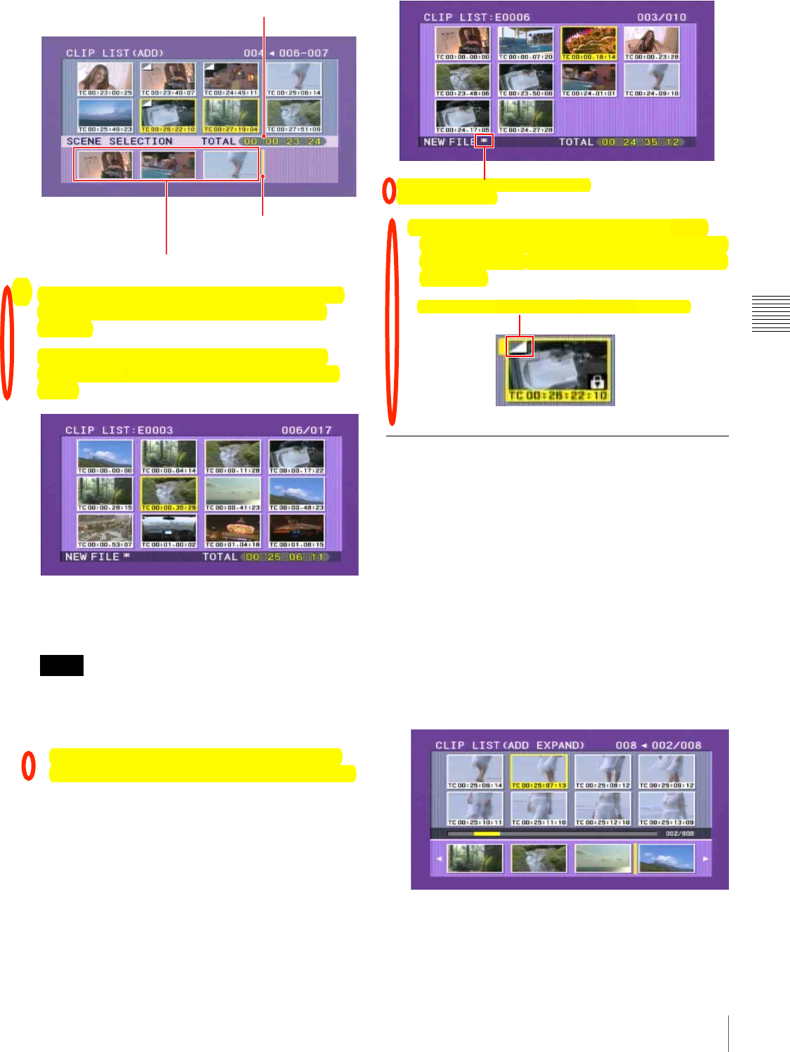
95
Creating Clip Lists
Chapter 4 Scene Selection
9
Add all the desired clips to the current clip list, and
press the RESET button on the right of the LCD
monitor.
You return to the clip list screen, which displays
thumbnails of the newly added clips (added as sub
clips).
10
Save the contents of the current clip list on the disc.
See “Saving the Current Clip List to Disc” on page 98.
• If the contents of the current clip list is not saved to
disc, then ejecting the disc, or powering off will
destroy the data. After creating a clip list, be sure to
save it to disc.
• An asterisk (*) appears after the date and time of
creation when a clip list has not been saved to disc.
• Even when clips whose thumbnail image (index
frame) is not the first frame are added to a clip list, it
is always the first frame that is displayed on the clip
list screen.
Adding Sub Clips Using the Expand
Function
You can use the expand function (see page 85) to divide a
sub clip and display thumbnails of the divisions. This
allows you to include a section of the sub clip.
Proceed as follows.
1
In the upper part of the scene selection screen, select
the sub clip for expanded display.
2
Press the DISPLAY/EXPAND button on the right of
the LCD monitor.
The upper part of the screen shows thumbnails for the
clip in eight divisions.
To vary the expansion ratio
Each time you press the DISPLAY/EXPAND button
changes the ratio through the sequence ×8 t ×64 t
×512.
Notes
Total duration of sub clips in the current clip list
I-bar cursor (shows insertion
position of next sub clip)
Thumbnails of the sub clips already added to the current clip list
Asterisk appears when clip list has not
been saved to disc.
Mark indicating that the thumbnail is not the first frame

96 Creating Clip Lists
Chapter 4 Scene Selection
To return to the previous setting, hold down the SHIFT
button and press the DISPLAY/EXPAND button to
step back one level.
The maximum number of divisions may be 512 or
greater when you expand clips with short recording
times. In this case, the interval between the expanded
thumbnail frames is fixed at 1 frame, which allows you
to view expanded thumbnails at a constant interval.
3
Use the SEL/SET button or MENU knob to select the
thumbnail for the part you want to include in the clip
list. To select two or more thumbnails, hold down the
SHIFT button and operate the MENU knob.
Even if more than one thumbnail is selected, the
addition to the current clip list is linked to a single sub
clip.
4
Press the SEL/SET button or MENU knob.
The clip selected in the upper part is added to the
current clip list in the lower part, as a sub clip.
The section from the selected thumbnail to the next
thumbnail is included as a sub clip.
Adding Sub Clips Using the Chapter
Function
You can use the chapter function (see page 85) to display
thumbnails of shot marks in clips on the disc, and include
sections of those clips in clip lists.
Proceed as follows.
1
In the scene selection screen, select the clip for chapter
display.
An “S” mark appears in the upper right of clips where
shot marks are set.
2
Press the COUNTER/CHAPTER button on the right
of the LCD monitor.
Thumbnails of the chapters in the specified clip appear
in the upper part of the scene selection screen.
3
Using the SEL/SET button or MENU knob, from the
positions of the essence marks recorded within this
clip, select the chapter for the part you want to include
in the clip list. To select two or more chapters, hold
down the SHIFT button and operate the MENU knob.
The section from the selected thumbnail to the next
thumbnail is included as a sub clip.
Even if more than one chapter is selected, the addition
to the current clip list is linked to a single sub clip.
4
Press the SEL/SET button or MENU knob.
The clip selected in the upper part is added to the
current clip list in the lower part, as a sub clip.
Note
Note
Note
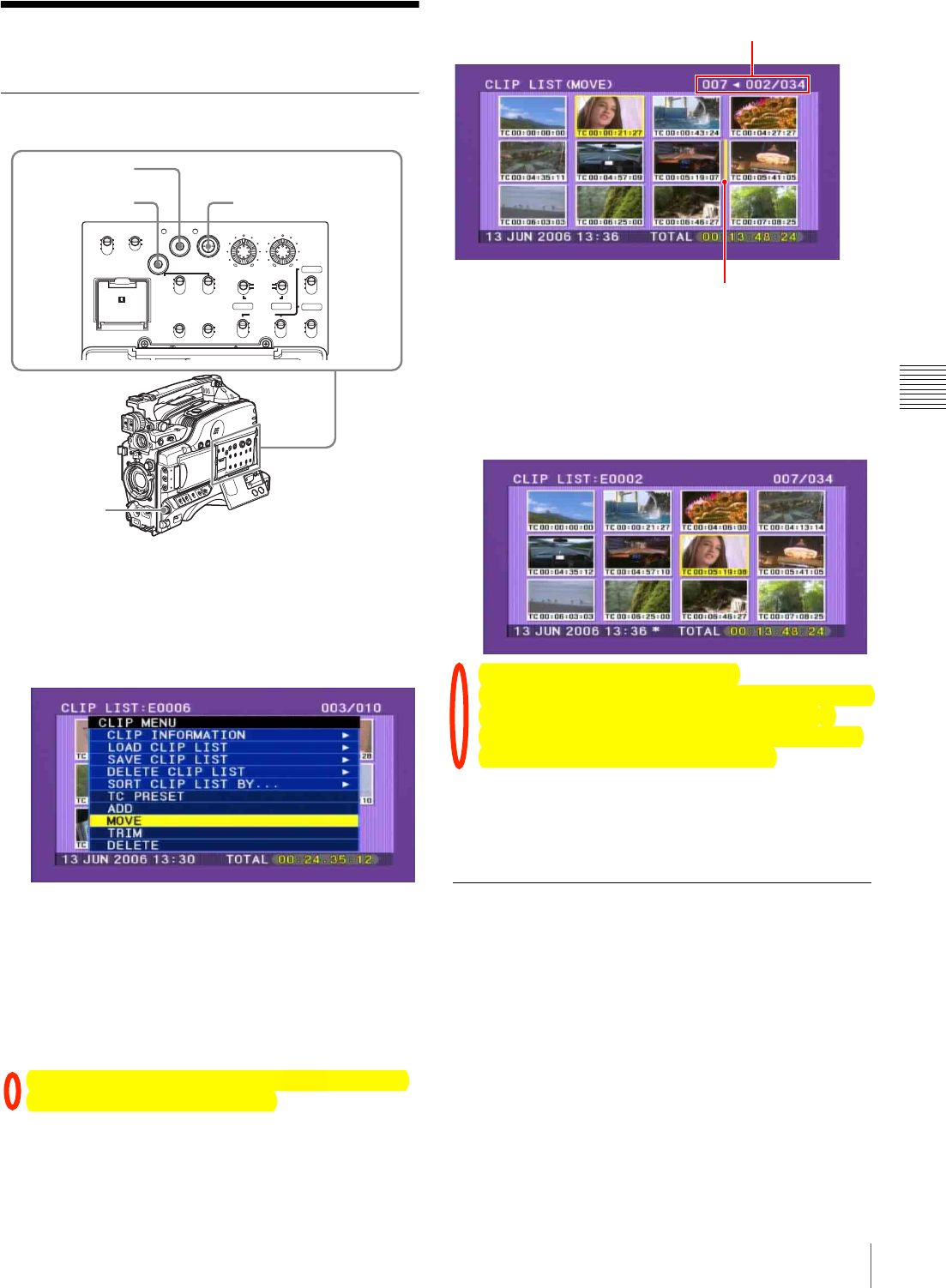
97
Editing Clip Lists
Chapter 4 Scene Selection
Editing Clip Lists
Reordering Sub Clips
Proceed as follows.
1
In the clip list screen, hold down the SHIFT button,
and press the SEL/SET button down (CLIP MENU).
The CLIP menu appears.
2
Use the SEL/SET button or MENU knob to select
“MOVE”, and press the button/knob.
This shifts to the MOVE screen.
3
Use the SEL/SET button (four-way arrow key) or
MENU knob to select the sub clip that you want to
move, and then press the button or knob.
To make a multiple selection, hold down the SHIFT
button, and turn the MENU knob.
An I-bar cursor appears, indicating the movement
destination.
4
Use the SEL/SET button or MENU knob to move the
I-bar cursor to the position to which you want to move,
and press the button/knob.
This changes the sequence of sub clips.
To continue moving sub clips
If you hold the SHIFT down when you press the SEL/
SET button or MENU knob, you return to step 3
instead of the CLIP menu after a clip is moved. This
allows you to continue moving sub clips
5
Save the contents of the current clip list to disc.
See “Saving the Current Clip List to Disc” on page 98.
Adjusting Sub Clip In/Out Points
(Trimming)
Proceed as follows.
1
Carry out step 1 of the procedure in “Reordering Sub
Clips” on page 97, to display the CLIP menu.
2
Use the SEL/SET button or MENU knob to select
“TRIM”, and press the button/knob.
This switches to the screen for selecting a thumbnail
for trimming.
CH-1
MIX
CH-2
CH-3
PRESET
AUTO
FRONT
WIRELESS
REAR
CH-1
MANUAL
AUDIO SELECT
AUDIO IN
F-RUN
REGEN
ON
OFF
SET
ON
OFF
CLOCK
F
W
R
F
W
R
R-RUN
MONITOR
FRONT MIC
LOW CUT VIDEO OUT
CHARACTER
AUDIO LEVEL
THUMBNAIL SUB CLIP
MIX
CH-4
CH-1/2
CH-3/4
SHIFT CLIP MENU
SEL/SET 0 10 0 10
ESSENCE
MARK
CH-2
CH-3
CH-4
LITHIUM BATT
SHIFT button SEL/SET button
THUMBNAIL
button
MENU knob
Indicates that 2nd sub clip will be
moved to position of 7th sub clip.
Cursor showing position to which
selected sub clip will be moved.

98 Editing Clip Lists
Chapter 4 Scene Selection
3
Use the SEL/SET button (four-way arrow key) or
MENU knob to select the desired sub clip, and press
the button/knob.
The first frame of the selected sub clip is displayed. In
this state you can play back or search the entire disc.
4
Carry out playback or search, to find the scene to be
the new In point or Out point of the selected sub clip.
You can also turn the MENU knob for a jog operation.
5
Use the SEL/SET button or MENU knob to select
“IN” or “OUT” on the screen, and press the button/
knob.
The set timecode value appears as “IN” or “OUT”.
To reset an In point or Out point
Select “IN” or “OUT” on the screen and then press the
RESET button on the right side of the LCD monitor.
The In or Out point returns to the value it had before
you entered the trim screen.
To cue up the In or Out point
(Do one of the following to cue up the In point.)
• With the SHIFT held down, press the PREV button.
• With the SEL/SET button pressed to the left, press
the PREV or NEXT button.
(Do one of the following to cue up the Out point.)
• With the SHIFT held down, press the NEXT button.
• With the SEL/SET button pressed to the right, press
the PREV or NEXT button.
6
When you are finished setting the In or Out point,
select “OK”.
The background of “OK” turns to yellow.
7
Press the SEL/SET button or MENU knob.
The trim is executed.
To continue trimming sub clips
With the SHIFT button held down, press the SEL/SET
button or the MENU knob. After the trim is executed,
you return to the screen of step 3 instead of the CLIP
menu. This allows you to continue trimming.
To cancel the trim
Press the SEL/SET button to the lower side (CLIP
MENU side).
8
Save the contents of the current clip list to disc.
See “Saving the Current Clip List to Disc” on page 98.
Deleting Sub Clips
Proceed as follows.
1
Carry out step 1 of the procedure in “Editing Clip
Lists” on page 97, to display the CLIP menu.
2
Use the SEL/SET button or MENU knob to select
“DELETE”, and press the button/knob.
This switches to the screen for selecting a sub clip to
be deleted.
3
Use the SEL/SET button (four-way arrow key) or
MENU knob to select the sub clip to be deleted, and
press the button/knob. To make a multiple selection,
hold down the SHIFT button, and turn the MENU
knob.
A confirmation message appears.
4
Select “OK”, and press the button/knob.
This carries out the deletion.
To continue deleting sub clips
With the SHIFT button held down, press the SEL/SET
button or the MENU knob. After the deletion is
executed, you return to the screen of step 3 instead of
the CLIP menu. This allows you to continue deleting.
5
Save the contents of the current clip list to disc.
Saving the Current Clip List to Disc
Proceed as follows.
1
Display the CLIP menu.
See “To display the CLIP menu” on page 100.
2
Use the SEL/SET button or MENU knob to select
“SAVE CLIP LIST” with the cursor in the CLIP
menu, and press the button/knob.
This displays the list of clip lists.
For a clip list in which no data has been stored, this
appears as “NEW FILE”.
To switch the information displayed for clip
lists
Press the SEL/SET button to the right side.
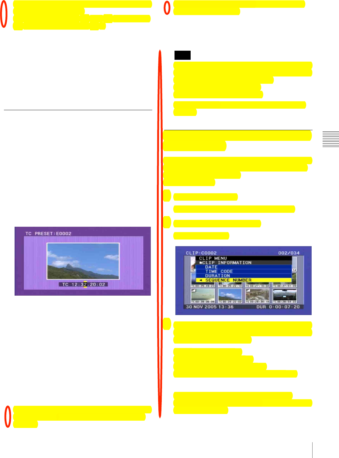
99
Editing Clip Lists
Chapter 4 Scene Selection
Each press switches the information displayed for clip
lists in the following order.
Date and time of creation t Title t Clip list name
t Date and time of creation t ...
3
Select the desired clip list name, and press the button/
knob.
This saves the current clip list to disc.
To apply a desired title or name to a clip list
Use the supplied PDZ-1 Proxy Browsing Software.
For details, see the PDZ-1 online help.
Setting the Start Timecode for the
Current Clip List
By default, the start timecode (LTC) for the current clip list
is set to 00:00:00:00.
To set this to a different value, proceed as follows.
1
Display the CLIP menu.
See “To display the CLIP menu” on page 100.
2
Use the SEL/SET button or MENU knob to align the
cursor with “TC PRESET”, and press the button/knob.
The display appears as in the following figure.
The timecode shown is the start timecode currently set
for the current clip list.
3
Press the SEL/SET button left and right to select the
desired time unit (any of HOUR, MIN, SEC, and
FRAME).
4
Press the SEL/SET button up or down, or turn the
MENU knob to display the desired value.
5
When all time units are set correctly, press the SEL/
SET button or MENU knob.
This sets the start timecode for the current clip list,
which will be used for playback.
To cancel the timecode setting, hold down the SHIFT
button, and press the SEL/SET button down (CLIP
MENU).
Alternatively, press the RESET button on the right
side of the LCD monitor.
6
Save the current clip list.
See “Saving the Current Clip List to Disc” on page 98.
The DF/NDF timecode setting of the current clip list is
set to the current setting of the camcorder when one of
the following operations is performed.
• When you add the first sub clip
• When you set the start timecode
See page 123 for more information about DF/NDF
settings.
To Switch the Information Displayed
on Thumbnails
You can switch the information displayed at the bottom of
thumbnails in the thumbnail screen. You can also select
display of sequence numbers.
Proceed as follows.
1
Display the CLIP menu.
See “To display the CLIP menu” on page 100.
2
Select “CLIP INFORMATION”.
A sub menu appears.
3
Use the SEL/SET button or MENU knob to select the
information to display from among the following, and
then press the button or knob.
DATE: Date of recording
TIME CODE: Start timecode
DURATION: Whole length of clip
SEQUENCE NUMBER: Thumbnail sequence
number
The factory default setting is “TIME CODE”.
The display below each thumbnail changes depending
on the item selected.
Note
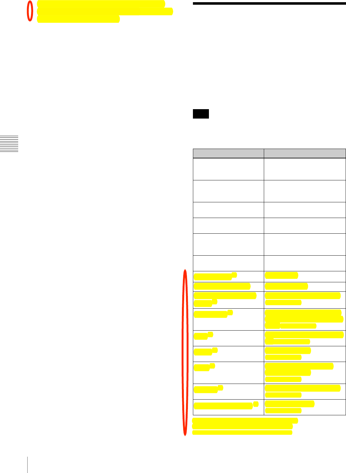
100 Managing Clip Lists
Chapter 4 Scene Selection
See “To switch the information displayed in the
thumbnail screen” (page 83) for more information
about SEQUENCE NUMBER. Managing Clip Lists
Using the CLIP menu, you can save created clip lists to
disc, read them from the disc into this unit, and delete them
from the disc.
To display the CLIP menu
In the thumbnail or clip list screen, hold down the SHIFT
button and press the SEL/SET button to the lower side
(CLIP MENU side).
The CLIP menu handles up to 99 clip lists.
The CLIP menu appears.
a) Displayed only in operating the thumbnail screen
b) Displayed only in operating the clip list screen
*=%@-'F)+P(;%#,)P%-,%#F(1+&-,G%&/(%*/+F&(1%'*1((,
Note
Item Function
CLIP INFORMATION Select the information to be
displayed below the thumbnails
!C##$%&'#"$B@$&7.$??*
LOAD CLIP LIST Load a clip list from the disc as
the current clip list !"##$
%&'# DED*
SAVE CLIP LIST Save the current clip list to the
disc!"##$%&'# ?B*
DELETE CLIP LIST Delete a clip list from the disc
!"##$%&'# DED*
SORT CLIP LISTS BY... You can sort the list of clip lists
by name or date and time of
creation !"##$%&'# DED*
SET INDEX PICTURE a) Change the thumbnail image of
a clip !"##$%&'# B@*
DELETE CLIP a) Delete a clip
LOCK/UNLOCK CLIP Lock or unlock a clip
LOCK OR DELETE ALL
CLIPS a)
Lock/unlook or delete all clips
!"##$%&'# BA*
TC PRESET b) Change the start timecode for
the current clip list to a desired
value !"##$%&'# ??*
ADD b) Add sub clips to the current clip
list$!"##$%&'# ?@*
MOVE b) Reorder sub clips
!"##$%&'# ?A*
TRIM b) Change the In point or Out
point of a sub clip
!"##$%&'# ?A*
DELETE b) Delete unnecessary sub clips
!"##$%&'# ?B*
DELETE SHOT MARK c) Delete a shot mark
!"##$%&'# B)*

101
Managing Clip Lists
Chapter 4 Scene Selection
To exit the CLIP menu
Carry out the same operation as when displaying the menu
(hold down the SHIFT button, and press the SEL/SET
button down (CLIP MENU)).
Loading a Clip List From the Disc as
the Current Clip List
Proceed as follows.
1
Display the CLIP menu.
See “To display the CLIP menu” on page 100.
2
Select “LOAD CLIP LIST”.
This displays the clip lists.
To switch the information displayed for clip
lists
Press the SEL/SET button to the right side.
Each press switches the information displayed for clip
lists in the following order.
Date and time of creation t Title t Clip list name
t Date and time of creation t ...
3
Select the desired clip list, and press the SEL/SET
button or MENU knob.
This loads the selected clip list as the current clip list.
To display thumbnails of the read-in
current clip list
1
Press the THUMBNAIL button to turn the
THUMBNAIL indicator on.
If the menu screen is displayed, move the MENU
switch to the OFF position and press the
THUMBNAIL button.
If you move the MENU switch to ON while
thumbnails are displayed, the thumbnail display
disappears, and the menu appears.
2
Hold down the SHIFT button and press the SEL/SET
button up to turn the SUB CLIP indicator on.
This displays thumbnails of the sub clips within the
clip list.
Deleting a Clip List From the Disc
Proceed as follows.
1
Display the CLIP menu.
See “To display the CLIP menu” on page 100.
2
Select “DELETE CLIP LIST”.
This displays the clip lists.
To switch the information displayed for clip
lists
Press the SEL/SET button to the right side.
Each press switches the information displayed for clip
lists in the following order.
Date and time of creation t Title t Clip list name
t Date and time of creation t ...
3
Select the clip list you want to delete, and press the
SEL/SET button or MENU knob.
A confirmation message appears.
4
Select OK, and press the SEL/SET button or MENU
knob.
This deletes the selected clip list from the disc.
To continue deleting other clip lists
After selecting “OK”, press the SEL/SET button while
holding down the SHIFT button. The selected clip list is
deleted, and you return to step 3 and can continue deleting
clip lists.
Sorting the List of Clip Lists
You can sort the list of clips lists that appears when you
select LOAD CLIP LIST and similar commands. Existing
clip lists can be sorted in order of name or in order of date
and time of creation.
Proceed as follows.
1
Display the CLIP menu.
See “To display the CLIP menu” (page 100).
2
Use the SEL/SET button or MENU knob to select
“SORT CLIP LISTS BY...”, and then press the button
or knob.
A screen like the one shown below appears.
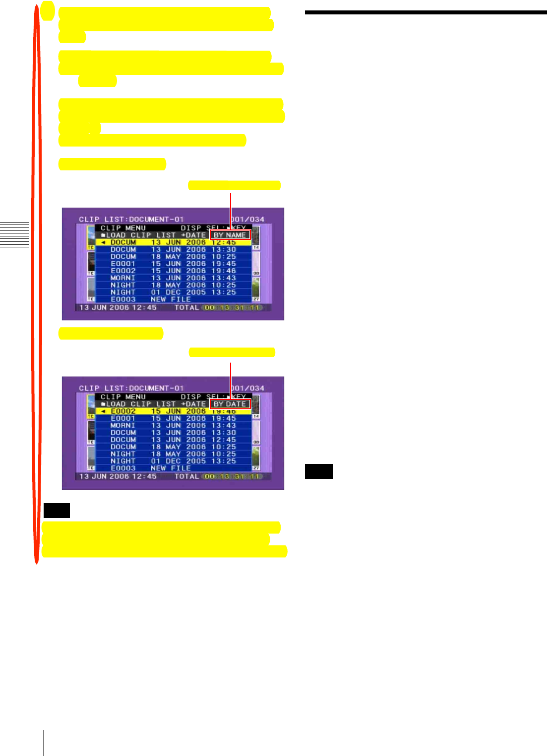
102 Using the PDZ-1 Proxy Browsing Software
Chapter 4 Scene Selection
3
Use the SEL/SET button or MENU knob to select
“NAME” or “DATE”, and then press the button or
knob.
NAME: Sort in ascending order by clip list name.
DATE: Sort by date of creation, with the newest clip
list first.
In the LOAD CLIP LIST and similar screens, the list
of existing clip lists is sorted by the method you chose
in step 3.
Unused clip lists are excluded from the sort.
If you selected “NAME”
If you selected “DATE”
Some characters in clip names, clip list names, and titles
may be converted to “s” characters for display in the
thumbnail screen and CLIP menu. For details, see page 78.
Using the PDZ-1 Proxy
Browsing Software
When a computer with the PDZ-1 Proxy Browsing
Software installed is connected to this unit, you can
transfer the proxy AV data and metadata files recorded on
a disc to the computer. On the computer side, PDZ-1
enables you to browse the proxy AV data, add or modify
metadata (titles, comments, essence marks, etc.), or create
a clip list.
The modified metadata and the created clip list can then be
written back to the disc loaded in this unit.
System requirements to use the PDZ-1
The following are required to use the PDZ-1.
• Computer:
PC with Intel Pentium III CPU, at least 1 GHz (installed
memory: at least 512 MB)
• Operating system: Microsoft Windows 2000 Service
Pack 4 or higher, or Microsoft Windows XP
Professional Service Pack 1 or higher
• Web browser: Internet Explorer 6.0 Service Pack 1 or
higher
• DirectX: DirectX 8.1b or higher
To install the PDZ-1
Insert the supplied CD-ROM (PDZ-1 Proxy Browsing
Software) in the CD-ROM drive of the computer and
execute the Setup.exe file, then follow the installation
instructions.
For details, refer to the ReadMe file in the CD-ROM.
Make sure that the hard disk drive on which the work
folder to store the material transferred from this unit has
adequate free space.
The amount of proxy AV data transferred is up to a
maximum of 2.8 GB per disc (LP format).
Note
BY NAME: Sort by name.
BY DATE: Sort by date.
Note

103
Menu Organization and Operation
Chapter
Chapter 5 Menu Displays and Detailed Settings
5
Menu Displays and
Detailed Settings
Menu Organization and Operation
The following chart shows the organization of menus in
this camcorder.
Note that the USER menu organization shown in the chart
is as registered at the factory.
For details about USER MENU CUSTOMIZE, see
“Editing the USER Menu” on page 133.
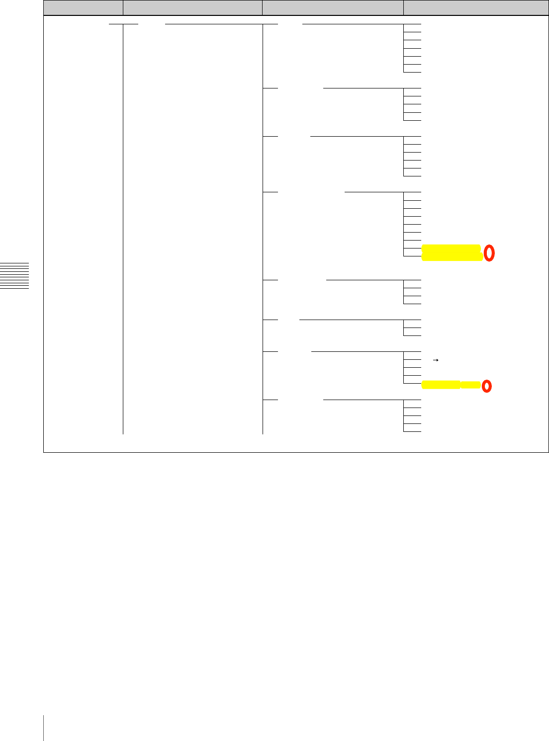
104 Menu Organization and Operation
Chapter 5 Menu Displays and Detailed Settings
Menu selection 1st level 2nd level 3rd level
TOP MENU USER PAINT
SCENE FILE
FORMAT
SPECIAL EFFECTS
ASSIGNABLE
DISC
OUTPUT
VF SETTING
A.IRIS
DETAIL LEVEL
MASTER BLACK
GAMMA SELECT
MASTER GAMMA
BLACK GAMMA
PRESET MATRIX SEL
1-5
STANDARD
SCENE RECALL
SCENE STORE
F.ID
SYSTEM
REC FORMAT
BIT RATE (HD)
AUDIO CH (HD)
ASPECT RATIO (DV)
COUNTRY
SLOW & QUICK [F350]
FRAME RATE [F350]
INTERVAL REC
INTERVAL TIME
NUMBER OF FRAME
NUMBER OF TIMES
PRE-LIGHTING
PICTURE CACHE
CACHE REC TIME
ASSIGN SW <1>
ASSIGN SW <2>
ASSIGN SW <3>
ASSIGN SW <4>
DELETE LAST CLIP
DELETE ALL CLIPS
QUICK FORMAT
COMPONENT OUT [F330]
HD SD (PLAY BACK)
VIDEO OUT SEL [F350]
i.LINK MODE
LIVE&PLAY [F350]
ZEBRA
ZEBRA SELECT
ZEBRA1 DET.LEVEL
DETAIL FREQ
VF ASPECT
(Continued) (Continued)
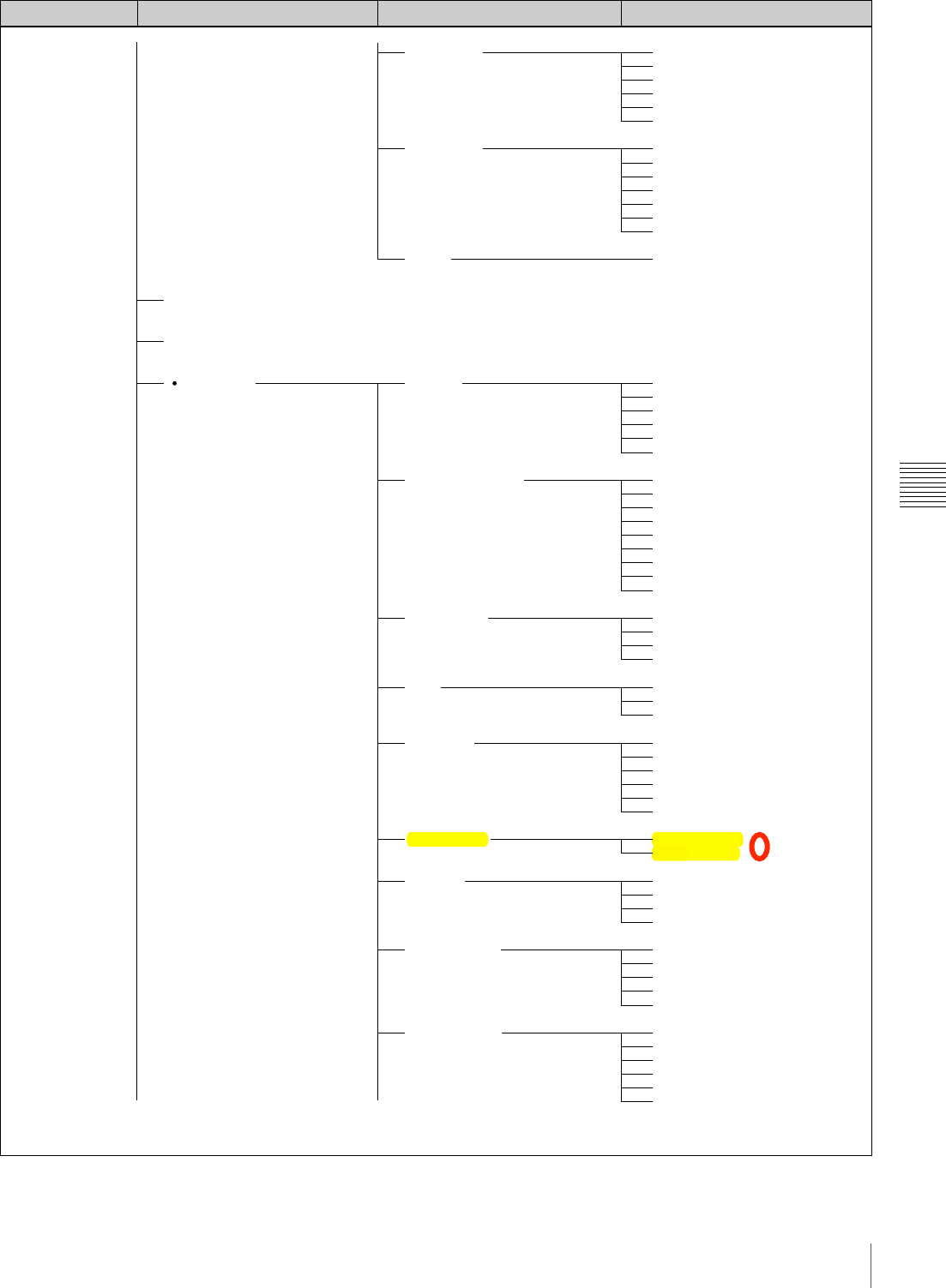
105
Menu Organization and Operation
Chapter 5 Menu Displays and Detailed Settings
Menu selection 1st level 2nd level 3rd level
USER MENU CUSTOMIZE
ALL
OPERATION
MARKER
SKIN DETAIL
RESET
FORMAT
SPECIAL EFFECTS
ASSIGNABLE
DISC
CLIP TITLE
FILE NAMING
GAIN SW
EZ MODE/TLCS
OFFSET WHITE
MARKER
CENTER
SAFETY ZONE
SAFETY AREA
ASPECT
ASPECT SELECT
SKIN DETAIL
SKIN DETAIL LVL
SKIN DETECT
SKIN AREA IND.
SKIN DTL SAT
SKIN DTL HUE
SKIN DTL WIDTH
ALL PRESET
SYSTEM
REC FORMAT
BIT RATE (HD)
AUDIO CH (HD)
ASPECT RATIO (DV)
COUNTRY
SLOW & QUICK [F350]
FRAME RATE [F350]
INTERVAL REC
INTERVAL TIME
NUMBER OF FRAME
NUMBER OF TIMES
PRE-LIGHTING
PICTURE CACHE
CACHE REC TIME
ASSIGN SW <1>
ASSIGN SW <2>
ASSIGN SW <3>
ASSIGN SW <4>
DELETE LAST CLIP
DELETE ALL CLIPS
QUICK FORMAT
TITLE
SELECT PREFIX
CLEAR NUMERIC
LOAD PREFIX DATA
PREFIX
NUMERIC
NAMING FORM
AUTO NAMING
GAIN LOW
GAIN MID
GAIN HIGH
GAIN TURBO
TLCS MODE
AGC LIMIT
AGC CHANGE POINT
AE LIMIT
AE CHANGE POINT
OFFSET WHITE <A>
WARM COOL <A>
COLOR FINE <A>
OFFSET WHITE <B>
WARM COOL <B>
COLOR FINE <B>
(Continued) (Continued)
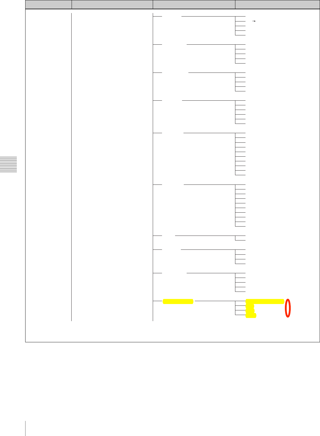
106 Menu Organization and Operation
Chapter 5 Menu Displays and Detailed Settings
Menu selection 1st level 2nd level 3rd level
OUTPUT
VIDEO OUT
VF SETTING
MARKER
VF DISP 1
VF DISP 2
LCD
SHOT ID
SHOT DISP
LENS FILE SEL
COMPONENT OUT [F330]
HD SD (PLAY BACK)
VIDEO OUT SEL [F350]
i.LINK MODE
LIVE&PLAY
VIDEO OUT VFDISP
VIDEO OUT MENU
VIDEO OUT TC
VIDEO OUT ZEBRA
VIDEO OUT MARKER
ZEBRA
ZEBRA SELECT
ZEBRA1 DET.LEVEL
DETAIL FREQ
VF ASPECT
MARKER
CENTER
SAFETY ZONE
SAFETY AREA
ASPECT
ASPECT SELECT
DISP REC FORMAT
DISP BIT RATE
DISP SYSTEM
DISP FRAME RATE
DISP 16:9
DISP ZOOM
DISP FOCUS
DISP BATT REMAIN
DISP REC/PLAY
DISP TIME CODE
DISP 5600K
DISP FILTER
DISP WHITE
DISP GAIN
DISP SHUTTER
DISP AUDIO
DISP DISC
DISP IRIS
DISP LOW LIGHT
DISP INTERVAL
LCD COLOR
LCD MARKER&ZEBRA
ID-1
ID-2
ID-3
ID-4
SHOT DATE
DATE MODE
SHOT TIME
TIME MODE
SHOT ID SEL
LENS FILE SELECT
F.ID
L.ID
L.MF
(Continued) (Continued)
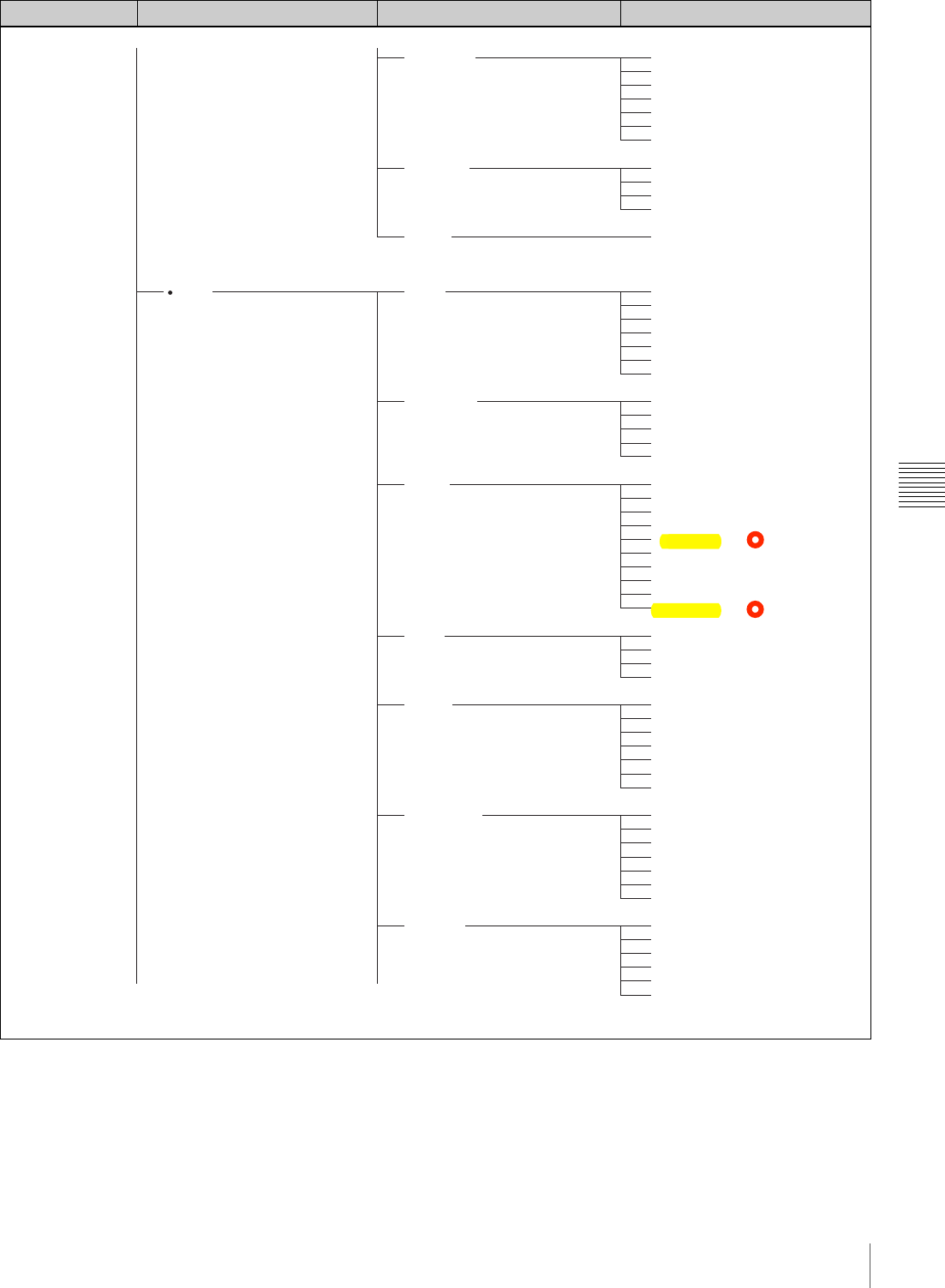
107
Menu Organization and Operation
Chapter 5 Menu Displays and Detailed Settings
Menu selection 1st level 2nd level 3rd level
PAINT
TIME/DATE
UMID SET
RESET
PAINT
SW STATUS
WHITE
KNEE
DETAIL
SKIN DETAIL
MATRIX 1
ADJUST
HOUR
MIN
SEC
YEAR
MONTH
DAY
COUNTRY CODE
ORGANIZATION
USER CODE
TIME ZONE: 00
ALL PRESET
A.IRIS
DETAIL LEVEL
MASTER BLACK
GAMMA SELECT
MASTER GAMMA
BLACK GAMMA
PRESET MTX SEL
GAMMA
MATRIX
KNEE
WHITE CLIP
DETAIL
COLOR TEMP <A>
C TEMP BAL <A>
R GAIN <A>
B GAIN <A>
D5600K<A>
COLOR TEMP <B>
C TEMP BAL <B>
R GAIN <B>
B GAIN <B>
D5600K<B>
KNEE POINT
KNEE SLOPE
KNEE SAT LEVEL
WHITE CLIP LEVEL
DETAIL LEVEL
DTL H/V RATIO
DETAIL FREQUENCY
APERTURE LEVEL
KNEE APT LEVEL
SD DETAIL
CROSS COLOR
SKIN DETAIL
SKIN DETAIL LVL
SKIN DETECT
SKIN AREA IND.
SKIN DTL SAT.
SKIN DTL HUE
SKIN DTL WIDTH
MATRIX
USER MATRIX
USER MATRIX SAT
USER MATRIX HUE
PRESET MTX
PRESET MTX SEL
(Continued) (Continued)
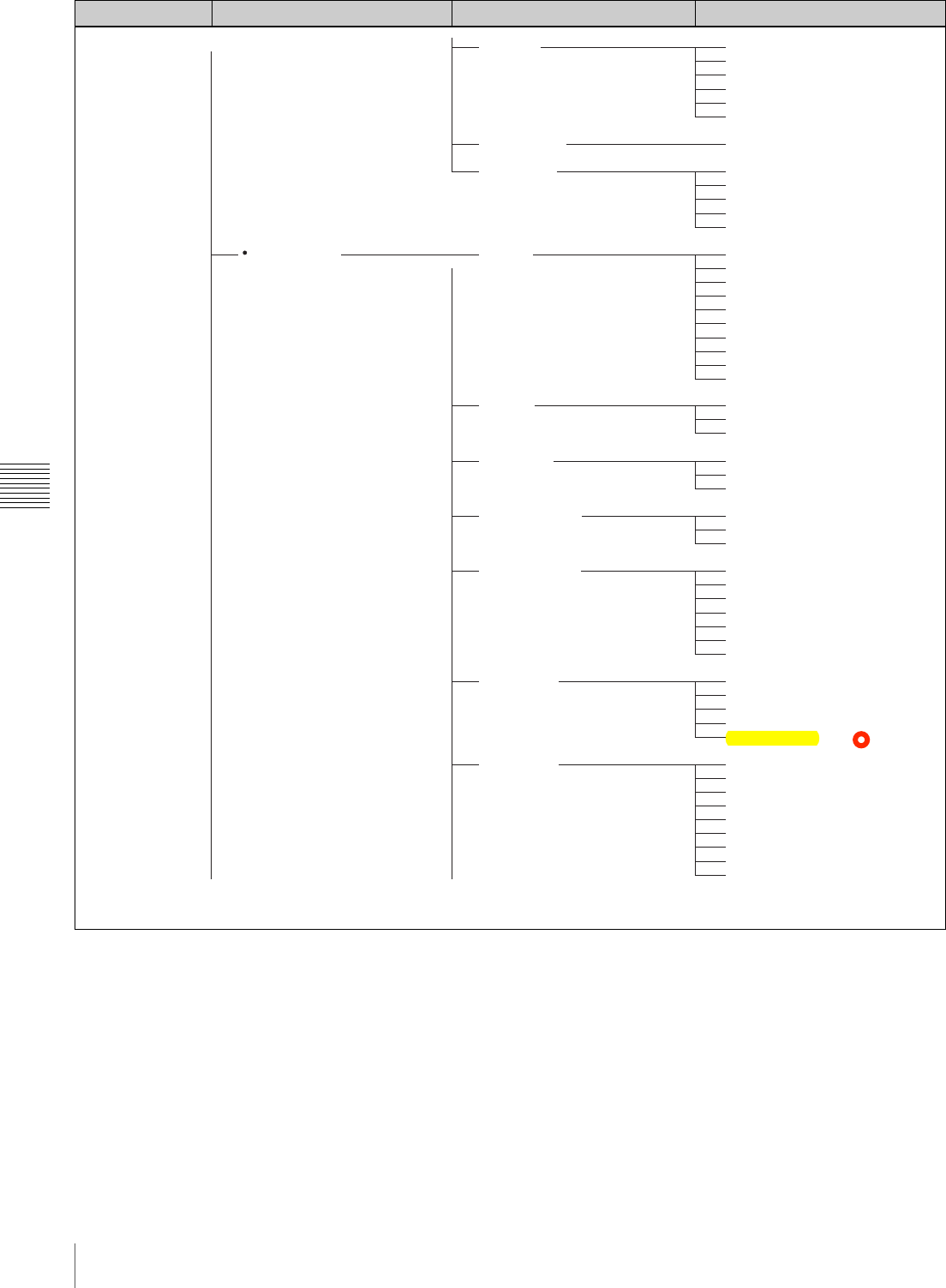
108 Menu Organization and Operation
Chapter 5 Menu Displays and Detailed Settings
Menu selection 1st level 2nd level 3rd level
MAINTENANCE
MATRIX 2
LOW KEY SAT
SCENE FILE
AUDIO-1
AUDIO-2
TIME CODE
ESSENCE MARK
WHITE SETTING
CAM CONFIG
BATTERY 1
USER MATRIX R-G
USER MATRIX R-B
USER MATRIX G-R
USER MATRIX G-B
USER MATRIX B-R
USER MATRIX B-G
L.KEY SAT LEVEL
1-5
STANDARD
SCENE RECALL
SCENE STORE
F.ID
AU REF LEVEL
AU AGC SPEC
AU LIMITER MODE
REAR MIC REF
FRONT MIC SELECT
AU CH12 AGC MODE
AU CH34 AGC MODE
AUDIO CH1 LEVEL
AUDIO CH2 LEVEL
AU SG (1KHz)
AU OUT LIMITER
HEADPHONE OUT
i.LINK AUDIO OUT
TC OUT
DF/NDF
UBIT
SHOTMARK 1
SHOTMARK 2
INDEX PIC. POS
COLOR TEMP <P>
C TEMP BAL <P>
WHITE SWITCH <B>
ATW SPEED
SHOCKLESS WHITE
AWB FIXED AREA
WHT FILTER INH
COLOR BAR SEL
REC TALLY
SLOW MOTION [F350]
SHT DISP MODE
IRIS OVERRIDE
Info BEFORE END
Info END
Sony BEFORE END
Sony END
Other BEFORE END
Other END
DC IN BEFORE END
DC IN END
DETECTED BATTERY
(Continued) (Continued)
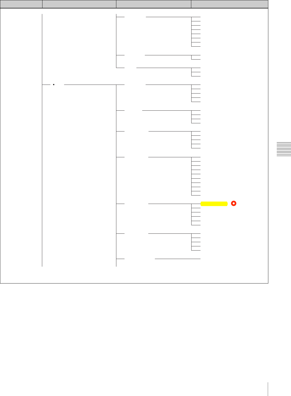
109
Menu Organization and Operation
Chapter 5 Menu Displays and Detailed Settings
Menu selection 1st level 2nd level 3rd level
FILE
BATTERY 2
GENLOCK
LENS
USER FILE
ALL FILE
SCENE FILE
LENS FILE 1
LENS FILE 2
LENS FILE 3
MEMORY STICK
TYPE DETECTION
SEGMENT No.7
SEGMENT No.6
SEGMENT No.5
SEGMENT No.4
SEGMENT No.3
SEGMENT No.2
SEGMENT No.1
GL H PHASE
H ADVANCE
ZOOM SELECT
ZOOM SPEED
AF DETECT AREA
USER FILE LOAD
USER FILE SAVE
F.ID
USER PRESET
CUSTOMIZE RESET
ALL FILE LOAD
ALL FILE SAVE
F.ID
ALL RESET
1-5
STANDARD
SCENE RECALL
SCENE STORE
F.ID
LENS FILE RECALL
LENS FILE STORE
F.ID
SOURCE
LENS NO OFFSET
IRIS GAIN
LENS AUTO RECALL
<LENS INFORMATION>
L.ID
L.MF
LENS M VMOD
LENS R FLARE
LENS G FLARE
LENS B FLARE
LENS W-R OFST
LENS W-B OFST
SHADING CH SEL
LENS R H SAW
LENS R H PARA
LENS R V SAW
LENS R V PARA
MS FORMAT
(Continued) (Continued)
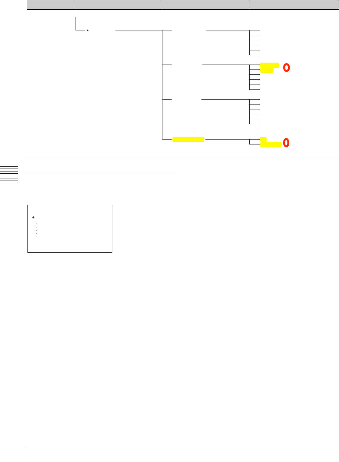
110 Menu Organization and Operation
Chapter 5 Menu Displays and Detailed Settings
TOP Menu
The TOP menu consists of the following submenus.
When you select an item in the TOP menu, this displays
the most recently shown page of the corresponding
submenu. When the submenu is selected for the first time,
the CONTENTS page appears.
USER menu
This menu allows you to add items from the
OPERATION, PAINT, MAINTENANCE, FILE, and
DIAGNOSIS menus to suit your needs. By gathering
frequently used items on the USER menu beforehand, you
can call up them quickly whenever you need them.
Usually by flicking the MENU switch to ON, the USER
menu is displayed.
USER MENU CUSTOMIZE menu
This menu allows you to add pages to or delete pages from
the USER menu to suit your needs.
ALL menu
This menu contains all items of the OPERATION, PAINT,
MAINTENANCE, FILE, and DIAGNOSIS menus as they
are in one menu.
OPERATION menu
This menu contains items for changing settings according
to conditions related to the subject when the camcorder is
being operated.
PAINT menu
This menu contains items for making detailed image
adjustments while using a waveform monitor to monitor
the waveforms output by the camera. Support of a video
engineer is usually required to use this menu. Although
you can also use an external remote control unit to set the
items on this menu, this menu is effective when using the
camcorder by itself outdoors.
MAINTENANCE menu
This menu includes contains items for making settings for
audio, timecode, essence marks, and battery.
FILE menu
This menu is for saving the adjusted data in the camcorder
memory or in a “Memory Stick”. The following files can
be saved.
User file
In the user file, the setting items and setting data of the
customized USER menu are saved. Once you save the user
Menu selection 1st level 2nd level 3rd level
DIAGNOSIS HOURS METER
DISC STATUS
CLIP STATUS
ROM VERSION
OPERATION
OPERATION (rst)
SPINDLE (rst)
LASER (rst)
LOADING (rst)
SEEK (rst)
USER ID
TITLE
REMAIN
REWRITE
SALVAGE
FILE SYSTEM
CLIP NO.
NAME
TITLE
RECORD DEVICE
SERIAL
DATE
TIME
AT
PACKAGE
<T OP M ENU>
U SER
U SER M EN U CUSTO MI ZE
A LL
OPERATION
PAINT
MAINT EN AN CE
FILE
DIAGNOSIS
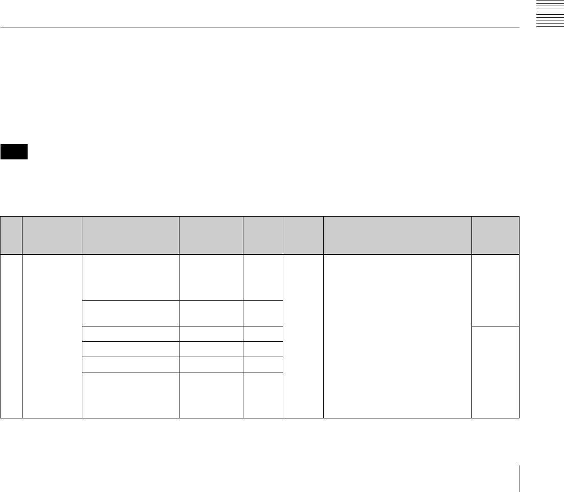
111
Menu Organization and Operation
Chapter 5 Menu Displays and Detailed Settings
file in a “Memory Stick”, you can easily set the USER
menu to your preference by loading the data from the
“Memory Stick”.
For details on the user file, see “Saving and Loading User
Files” on page 146.
ALL file
In the ALL file, the setting data of all of the menus are
saved. Once a camcorder is set according to your
preferences and you save its ALL file in a “Memory
Stick”, you can easily set other camcorders to the settings
of the camcorder that you already set by loading the data
from the “Memory Stick”.
Items included in the ALL file are marked with an “A” in
the “File” column on the menu list.
Scene file
In the scene file, the setting values of event items adjusted
to shoot a particular scene are saved. You can save up to
five scene files in the camcorder memory and up to 100
scene files in a “Memory Stick”. For example, first adjust
the settings to shoot a particular scene at the rehearsal and
then save them as a scene file. Then load this file before the
actual shooting so that you can quickly recreate setup
conditions that are the same as those in rehearsal.
Items included in the scene file are marked with an “Sc”
in the “File” column on the menu list.
Lens file
In the lens file, the setting data used to compensate for the
characteristics of lenses, such as flare, white shading,!and
auto iris gain, is saved. You can save up to 32 lens files in
the camcorder memory and up to 100 lens files in a
“Memory Stick”.
Items included in the lens file are marked with an “L” in
the “File” column on the menu list.
DIAGNOSIS menu
This menu shows the digital hours meter, and disc and clip
status information.
Menu List
For settings registered on a USER menu page at the
factory, the “USER menu page” colomn in the following
list indicates the number of that page.
The USER MENU CUSTOMIZE menu allows you to add
and delete pages to and from the USER menu to suit your
requirements.
When the setting range in the “Settings” column is
surrounded by parentheses ( ), the setup value is a relative
value. The setting range shown on the menu screen may
differ from what is shown in this manual.
“File” column
The letters in the “File” column stand for the following.
A: Items saved in the ALL file
Sc: Items saved in the scene file
L: Items saved in the lens file
St: Items whose setting is changed by the STANDARD
operation
OPERATION menu
Note
No. Page Item Settings Default USER
menu
page
Description File
01 FORMAT SYSTEM 60I / 30P /
23.9P
(PAL: 50I /
25P)
60I (50I) 03 C##$5C#1#8/07'$/3#$F#8,-.07'$
+,-9&/:$,7$%&'#$)B;
–
REC FORMAT MPEG HD /
DVCAM MPEG
HD
BIT RATE (HD) HQ / SP / LP SP A
AUDIO CH (HD) 2CH / 4CH 4CH
ASPECT RATIO (DV) 16:9 / 4:3 16:9
COUNTRY NTSC AREA /
NTSC(J)
AREA / PAL
AREA
–
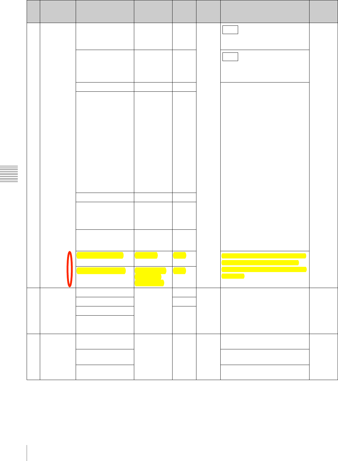
112 Menu Organization and Operation
Chapter 5 Menu Displays and Detailed Settings
02 SPECIAL
EFFECTS SLOW & QUICK ON / OFF OFF 04
Selects whether to use the slow &
quick-motion function.
A
FRAME RATE 1 to 30 (25) ,
60 (50) Fps 30P
Sets the shooting frame rate.
(When the slow & quick-motion
function is enabled)
INTERVAL REC ON / OFF OFF C##$5<09#G1&%"#$H0.#,$F#8,-.07'$
!5I7/#-J&1$F#8,-.07':$+K78/0,7*:$,7$
%&'#$AD;
INTERVAL TIME 1SEC to
10SEC /
15SEC /
20SEC /
30SEC /
40SEC /
50SEC,
1MIN to
10MIN /
15MIN /
20MIN /
30MIN /
40MIN /
50MIN,
1H to 6H /
12H / 24H
1SEC
NUMBER OF FRAME 1F / 3F / 6F 1F
NUMBER OF TIMES CONT / 50 /
100 / 200 /
300 / 500 /
800 / 1000
CONT
PRE-LIGHTING OFF / 2SEC /
5SEC /
10SEC
OFF
PICTURE CACHE OFF/ON OFF C##$5C/&-/07'$&$C3,,/$L0/3$&$+#M$
C#8,7."$,N$O-#GC/,-#.$O08/K-#$
P&/&$!O08/K-#$Q&83#$+K78/0,7*:$,7$
%&'#$AR;
CACHE REC TIME 0-2s/2-4s/4-
6s/6-8s/8-
10s/10-12s
0-2s
03
ASSIGNABLE
ASSIGN SW <1> OFF /
MARKER /
ATW / LENS
RET / REC
SWITCH /
TURBO
SWITCH, etc.
EZMOD 05 C##$5S""0'707'$+K78/0,7"$/,$
SCCITU$CM0/83#":$,7$%&'#$DR(;
A
ASSIGN SW <2>
IRRCN
ASSIGN SW <3> OFF
ASSIGN SW <4>
04 DISC DELETE LAST CLIP EXEC EXEC 06 Deletes a clip recorded on the disc. –
DELETE ALL CLIPS Deletes all clips recorded on the
disc.
QUICK FORMAT Formats the disc. Any recorded
content is lost.
No. Page Item Settings Default USER
menu
page
Description File
F350
F350
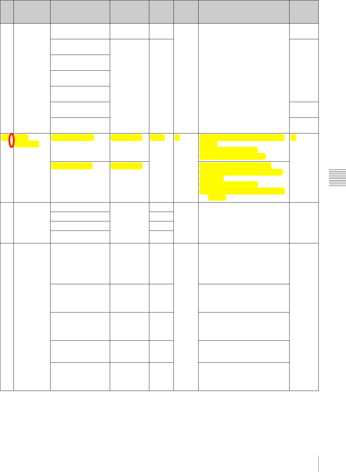
113
Menu Organization and Operation
Chapter 5 Menu Displays and Detailed Settings
05 CLIP TITLE CLIP TITLE ENABL /
DSABL DSABL – C##$5S""0'707'$V"#-GP#N07#.$Q10%$
<0/1#"$SK/,9&/08&11W:$,7$%&'#$A);
A
TITLE EXEC – –
SELECT PREFIX
CLEAR NUMERIC
LOAD PREFIX DATA
PREFIX A
NUMERIC –
06 FILE
NAMING NAMING FORM FREE/C**** C**** – Specify the clip and clip list name
format
C****: Standard format
FREE: Enable free format
A
AUTO NAMING TITLE/C**** Specify the format of the file
names generated when clips are
recorded
C****: Standard format
TITLE: Assign the same name as
clip title
07 GAIN SW GAIN LOW –3dB / 0dB /
3dB / 6dB /
9dB / 12dB /
18dB / 24dB /
30dB / 36dB /
42dB / 48dB
0dB – C##$5C#//07'$T&07$H&1K#"$N,-$/3#$
TSIU$CM0/83$O,"0/0,7":$,7$%&'#$
DRE;
A
GAIN MID 9dB
GAIN HIGH 18dB
GAIN TURBO 42dB
08 EZ MODE/
TLCS TLCS MODE AGC&AE /
AGC / AE AGC&
AE – Selects the TLCS function in EZ
mode.
AGC&AE: automatic gain and
shutter control
AGC: automatic gain control only
AE: automatic shutter control only
A
AGC-LIMIT 0 / 3 / 6 / 9 /
12 / 15 / 18dB
(normal
setting value)
18dB Sets the upper limit for AGC
adjustment. This function operates
only when using the EZ mode.
AGC CHANGE
POINT OPEN / F2 /
F2.8 / F4 /
F5.6
F2.8 Sets the f-stop for switching from
automatic iris adjustment to AGC.
This function operates only when
using the EZ mode.
AE-LIMIT 1/100 to
1/250 1/250 Sets the upper limit for shutter
adjustment. This function operates
only when using the EZ mode.
AE CHANGE POINT F5.6 / F8 /
F11 / F16
(normal
setting value)
F16 Sets the f-stop for switching from
automatic iris adjustment to AE.
This function operates only when
using the EZ mode.
No. Page Item Settings Default USER
menu
page
Description File
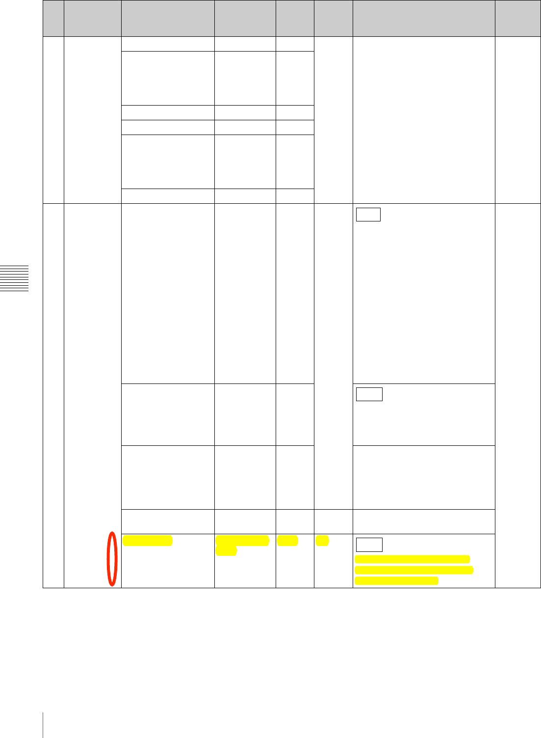
114 Menu Organization and Operation
Chapter 5 Menu Displays and Detailed Settings
09 OFFSET
WHITE OFFSET WHITE <A> OFF / ON OFF – C##$5C%#80NW07'$&7$XNN"#/$N,-$/3#$
SK/,$L30/#$6&1&78#$C#//07':$,7$
%&'#$DRD;
A
WARM-COOL <A> Display color
temperature
(converted
from R / B
Gain).
3200
COLOR FINE <A> (–99 to 99) 0
OFFSET WHITE <B> OFF/ON OFF
WARM-COOL <B> Display color
temperature
(converted
from R/B
Gain).
3200
COLOR FINE <B> (–99 to 99) 0
10 OUTPUT COMPONENT OUT AUTO /
HD YPbPr /
SD YPbPr
AUTO 07
Selects the output from the BNC
connector on the side panel of this
unit.
AUTO: Switch between HD YPbPr
and SD YPbPr, according to
the recording format. (For both
recording and playback)
HD YPbPr: Regardless of the
recording format, output HD
YPbPr when recording. Output
SD YPbPr only when playing
back DVCAM format.
SD YPbPr: Regardless of the
recording format, output SD
YPbPr. (For both recording and
playback)
A
VIDEO OUT SEL VBS / HD Y VBS
Selects the output from the VIDEO
OUT connector.
VBS: Output a composite signal.
HD Y: Output an HD Y signal.
HD$SD (PLAY
BACK) 16:9 / 4:3 16:9 Selects the aspect ratio for down-
converted output to an SD monitor
of playback of material recorded in
HD format.
You can select 16:9 (squeeze) or
4:3 (crop).
i.LINK MODE AV/C /FAM AV/C – Selects the function of the i.LINK
connector.
LIVE&PLAY OFF/HDSDI/
VBS OFF 07
C##$5H0#M07'$Q&9#-&$H0.#,$
PK-07'$O1&W4&8=$!Y0J#$Z$O1&W$
+K78/0,7*:$,7$%&'#$A?;
No. Page Item Settings Default USER
menu
page
Description File
F330
F350
F350

115
Menu Organization and Operation
Chapter 5 Menu Displays and Detailed Settings
11 VIDEO OUT VIDEO OUT VFDISP OFF / ON ON – Selects whether or not the VF
DISP display signal is mixed to the
output signal from the VIDEO OUT
connector.
A
VIDEO OUT MENU Selects whether or not the menu
display signal is mixed to the
output signal from the VIDEO OUT
connector.
VIDEO OUT TC Selects whether or not the
timecode is mixed to the output
signal from the VIDEO OUT
connector.
VIDEO OUT ZEBRA OFF Selects whether or not the zebra
mark display signal is mixed to the
output signal from the VIDEO OUT
connector.
VIDEO OUT
MARKER Selects whether or not the marker
signal is mixed to the output signal
from the VIDEO OUT connector.
12 VF
SETTING ZEBRA OFF / ON OFF 08 C##$5C#//07'$/3#$H0#MN07.#-$C8-##7$
P0"%1&W:$,7$%&'#$D@B;
–
ZEBRA SELECT 1 / 2 / BOTH 1 A
ZEBRA1 DET. LEVEL 30% to 107%
(in 1% steps) 70%
DETAIL FREQ NORM /
HIGH HIGH
VF ASPECT AUTO / 4:3 AUTO
13 MARKER MARKER OFF / ON OFF 09 C##$5C#//07'$/3#$[&-=#-$P0"%1&W:$
,7$%&'#$D@A;
A
CENTER ON
SAFETY ZONE
SAFETY AREA 80% / 90% /
92% / 95% 90%
ASPECT OFF / ON OFF
ASPECT SELECT 14:9 / 13:9 /
4:3 4:3
14 VF DISP 1 DISP REC FORMAT OFF / ON ON – C##$5C#1#8/07'$/3#$P0"%1&W$I/#9":$
,7$%&'#$D@>;
A
DISP BIT RATE
DISP SYSTEM
DISP FRAME RATE
DISP 16:9
DISP ZOOM
DISP FOCUS
DISP BATT REMAIN INT / VOLT /
AUTO AUTO
DISP REC / PLAY OFF / ON ON
DISP TIME CODE OFF
No. Page Item Settings Default USER
menu
page
Description File

116 Menu Organization and Operation
Chapter 5 Menu Displays and Detailed Settings
15 VF DISP 2 DISP 5600K OFF / ON ON – C##$5C#1#8/07'$/3#$P0"%1&W$I/#9":$
,7$%&'#$D@>;
A
DISP FILTER
DISP WHITE
DISP GAIN
DISP SHUTTER
DISP AUDIO
DISP DISC
DISP IRIS
DISP LOW LIGHT
DISP INTERVAL
16 LCD LCD COLOR –137 to 62 0 – Adjusts the LCD color. A
LCD MARKER &
ZEBRA ON / OFF ON Selects whether to add the marker
and zebra to the LCD display, in
the same way as in the viewfinder.
17 SHOT ID ID-1 Displays
character
input mode
(up to 12
characters).
Blank – C##$5C#//07'$/3#$C3,/$IP:$,7$%&'#$
D@?;
A
ID-2
ID-3
ID-4
18 SHOT DISP SHOT DATE OFF / ON OFF – C##$5F#8,-.07'$C3,/$P&/&$
CK%#-09%,"#.$,7$/3#$Q,1,-$6&-":$
,7$%&'#$D@B;
A
DATE MODE Y/M/D /
M/D/Y /
D/M/Y
Y/M/D
SHOT TIME OFF / ON OFF
TIME MODE 12H / 24H 12H
SHOT ID SEL OFF / ID-1 /
ID-2 / ID-3 /
ID-4
OFF
19 LENS FILE
SEL LENS FILE SELECT 1 to 32 – – Selects a lens file. Up to 32 files
can be registered. L
F.ID –Indicates the name of the selected
lens file.
L.ID Indicates the name of the lens file
corresponding to the connected
serial lens.
L.MF Indicates the fabricator of the
connected serial lens.
20 TIME / DATE ADJUST Displays the
TIME
ADJUST
selection
screen.
EXEC – C##$5C#//07'$/3#$P&/#$&7.$<09#$,N$
/3#$I7/#-7&1$Q1,8=:$,7$%&'#$@?;
–
HOUR 00 to 23 Internal
clock
MIN 00 to 59
SEC
YEAR 00 to 99
MONTH 01 to 12
DAY 01 to 31
No. Page Item Settings Default USER
menu
page
Description File

117
Menu Organization and Operation
Chapter 5 Menu Displays and Detailed Settings
21 UMID SET COUNTRY CODE 4-byte
alphanumeric
strings
– – C##$5V"07'$V[IP$P&/&:$,7$%&'#$
DAD;
A
ORGANIZATION
USER CODE
TIME ZONE 00 to xx 00
22 RESET ALL PRESET EXEC EXEC 11 Resets all settings at the USER
level. –
No. Page Item Settings Default USER
menu
page
Description File
118 Menu Organization and Operation
Chapter 5 Menu Displays and Detailed Settings
PAINT menu
No. Page Item Settings Default USER
menu
page
Description File
01 PAINT A.IRIS –1.0 / –0.5 /
±0 / +0.5 /
+1.0
± 0 01 – –
DETAIL LEVEL – 0 Detail level adjustment A, Sc, St
MASTER BLACK – Master black level adjustment
GAMMA SELECT STD /
CINE1 /
CINE2 /
CINE3 /
CINE4
STD C##$5C#1#8/07'$T&99&$<&41#":$,7$
%&'#$DR(;
MASTER GAMMA (–99 to 99) 0 Sets master gamma correction
curve.
BLACK GAMMA (–99 to 99) Black gamma correction
PRESET MTX SEL STD / HISAT /
FL / CINE STD Matrix selection
02 SW STATUS GAMMA OFF / ON ON – Turns the gamma correction on or
off. A, Sc, St
MATRIX Turns the linear matrix correction
on or off.
KNEE Turns the knee correction on or off.
WHITE CLIP Turns the white clipping correction
on or off.
DETAIL Turns the detail signal on or off.
03 WHITE COLOR TEMP <A> Display color
temperature
(converted
from R / B
Gain).
3200 – Sets the color temperature of
WHITE A. A
C TEMP BAL <A> (–99 to 99) 0 Adjusts the value more precisely
when the color temperature
adjustment through COLOR TEMP
is not satisfactory.
R GAIN <A> Only the value of R GAIN is
changed.
B GAIN <A> Only the value of B GAIN is
changed.
D5600K<A> ON/OFF OFF Turns the WHITE A electronic
5600K filter on or off.
COLOR TEMP <B> Display color
temperature
(converted
from R / B
Gain).
3200 Sets the color temperature of
WHITE B.
C TEMP BAL <B> (–99 to 99) 0 Adjusts the value more precisely
when the color temperature
adjustment through COLOR TEMP
is not satisfactory.
R GAIN <B> Only the value of R GAIN is
changed.
B GAIN <B> Only the value of B GAIN is
changed.
D5600K<B> ON/OFF OFF Turns the WHITE B electronic
5600K filter on or off.

119
Menu Organization and Operation
Chapter 5 Menu Displays and Detailed Settings
04 KNEE KNEE POINT 50.0 to 109 .0
(in 0.1 steps) 85.0 – Sets the knee point level. A, Sc, St
KNEE SLOPE – 0 Sets the knee slope level.
KNEE SAT LEVEL (–99 to 99) Sets the knee saturation level.
WHITE CLIP LEVEL 100.0 to
109.5
(in 0.1 steps)
108.0 Adjusts the white clipping level.
05 DETAIL DETAIL LEVEL – 0 – Sets the general level of the detail
signal. A, Sc, St
DTL H/V RATIO Sets the level of the V detail signal.
DETAIL
FREQUENCY Sets the frequency of the H detail
signal.
APERTURE LEVEL Sets the aperture level.
KNEE APT LEVEL Sets the knee aperture level.
SD DETAIL LOW / MID /
HIGH MID Detail setting for down-converted
SD
CROSS COLOR OFF / ON ON Turns the cross color component
on or off.
06 SKIN
DETAIL SKIN DETAIL OFF / ON OFF 10 Sets the skin detail on or off. A, Sc, St
SKIN DETAIL LVL – 0 Sets the detail level of detected
color.
SKIN DETECT Moves to
color
detection
page.
EXEC Detects the color for skin detail;–
SKIN AREA IND OFF / ON OFF Turns the indicator of detected
color on or off. St
SKIN DTL SAT (–99 to 99) 0 Adjusts the saturation level for skin
detail. A, Sc, St
SKIN DTL HUE 0 to 359 0 Adjusts the center phase for skin
detail.
SKIN DTL WIDTH 0 to 90 40 Adjusts the width for skin detail.
No. Page Item Settings Default USER
menu
page
Description File
120 Menu Organization and Operation
Chapter 5 Menu Displays and Detailed Settings
07 MATRIX 1 MATRIX OFF / ON ON – Turns the linear matrix correction
and user matrix correction
functions on or off.
A, Sc, St
USER MATRIX OFF Turns the user matrix correction
function on or off.
USER MATRIX SAT (–99 to 99) 0 Adjusts the saturation level
affected by the user matrix
correction function.
USER MATRIX HUE Adjusts the color phase affected by
the user matrix correction function.
PRESET MTX ON / OFF ON Turns the preset matrix correction
function on and off.
PRESET MTX SEL STD / HISAT /
FL / CINE STD When PRESET MTX is set to ON,
selects the matrix adjustment
value.
STD: settings for standard
shooting conditions
HISAT: settings for high saturation
shooting
FL: settings for fluorescent
illumination
CINE: settings to evoke the
impression of film camera
shooting
08 MATRIX 2 USER MATRIX R-G (–99 to 99) 0 – Sets the arbitrary R-G user-set
matrix coefficients. A, Sc, St
USER MATRIX R-B Sets the arbitrary R-B user-set
matrix coefficients.
USER MATRIX G-R Sets the arbitrary G-R user-set
matrix coefficients.
USER MATRIX G-B Sets the arbitrary G-B user-set
matrix coefficients.
USER MATRIX B-R Sets the arbitrary B-R user-set
matrix coefficients.
USER MATRIX B-G Sets the arbitrary B-G user-set
matrix coefficients.
09 LOW KEY
SAT L.KEY SAT LEVEL (–99 to 99) 0 – Sets the saturation level of the low
luminance part. A, Sc, St
No. Page Item Settings Default USER
menu
page
Description File

121
Menu Organization and Operation
Chapter 5 Menu Displays and Detailed Settings
10 SCENE FILE s1 –
STANDARD
02 Recalls a scene file saved in the
camcorder memory. –
s2
s3
s4
s5
sSTANDARD – – Clears all current detail-adjusted
settings and switch settings and
returns the settings to the standard
settings saved in the reference file.
SCENE RECALL Displays the
SCENE FILE
selection
screen.
EXEC Recalls a scene file from the
camcorder memory or the
“Memory Stick”.
SCENE STORE Stores a scene file in the
camcorder memory or the
“Memory Stick”.
F. ID Displays
character
input mode
(up to 16
characters).
Blank Sets the File ID. Sc
No. Page Item Settings Default USER
menu
page
Description File

122 Menu Organization and Operation
Chapter 5 Menu Displays and Detailed Settings
MAINTENANCE menu
No. Page Item Settings Default USER
menu
page
Description File
01 AUDIO-1 AU REF LEVEL –20 / –18 /
–16 / –12 dB –20 dB – Sets the output level of the 1 kHz
test signal. A
AU AGC SPEC –6 / –9 / –12 /
–15 / –17 dB –6 dB AGC characteristic (saturation
level) setting
AU LIMITER MODE OFF / –6 /
–9 / –12 /
–15 / –17 dB
OFF During manual adjustment of audio
input levels, selects the limitter
characteristics (saturation level) for
large input signals.
REAR MIC REF –60 / –50 /
–40 dB –60 dB Selects the reference input level
when the AUDIO IN CH1 switch is
set to MIC.
FRONT MIC SELECT MONO /
STEREO STEREO Input mode selection for front
microphone
AU CH12 AGC MODE MONO /
STEREO MONO Selects whether to carry out
automatic adjustment of the input
levels of analog audio signals
recorded on channels 1 and 2
independently for the two channels
or to carry it out in stereo mode.
AU CH34 AGC MODE MONO /
STEREO Selects whether to carry out
automatic adjustment of the input
levels of analog audio signals
recorded on channels 3 and 4
independently for the two
channels, to carry it out in stereo
mode, or not at all.
AUDIO CH1 LEVEL SIDE1 /
FRONT / F +
S1
FRONT When recording audio on channel
1, selects which knob is used for
adjustment.
SIDE1: Adjust with the left-hand
AUDIO LEVEL knob on the
side control panel.
FRONT: Adjust with the AUDIO
LEVEL knob on the front.
F + S1: Allow adjustment with
either of the left-hand AUDIO
LEVEL knob on the side control
panel or the AUDIO LEVEL
knob on the front. (The two
knobs function in linkage.)
AU CH2 LEVEL SIDE2 /
FRONT / F +
S2
When recording audio on channel
2, selects which knob is used for
adjustment.
SIDE2: Adjust with the right-hand
AUDIO LEVEL knob on the
side control panel.
FRONT: Adjust with the AUDIO
LEVEL knob on the front.
F + S2: Allow adjustment with
either of the right-hand AUDIO
LEVEL knob on the side control
panel or the AUDIO LEVEL
knob on the front. (The two
knobs function in linkage.)

123
Menu Organization and Operation
Chapter 5 Menu Displays and Detailed Settings
01 AUDIO-1 AU SG (1KHz) ON / OFF /
AUTO OFF – In the color bar mode, selects
whether to output a 1 kHz test
signal.
ON: Output.
OFF: Do not output.
AUTO: Output the test signal only
when the AUDIO SELECT
(CH-1) switch is set to AUTO.
A
02 AUDIO-2 AU OUT LIMITER ON / OFF ON – Turns the audio output limitter on
or off A
HEADPHONE OUT STEREO /
MONO MONO Selects whether the earphones are
monaural or stereo.
i.LINK AUDIO OUT 2CH / 4CH 2CH 2CH: Output channels 1 and 2 (16
bits, 48 ksps)
4CH: Output channels 1 to 4 (12
bits, 32 ksps)
03 TIMECODE TC OUT AUTO /
GENE AUTO – Timecode output setting
AUTO: For recording, the timecode
generator value is output, and
for playback, the value from
timecode reader is output.
GENE: The timecode generator
value is output for both
recording and playback.
A
DF / NDF DF / NDF DF DF / NDF setting
DF: drop-frame mode
NDF: non-drop-frame mode
UBIT FIX / TIME FIX Selects the user bit contents.
04 ESSENCE
MARK SHOTMARK 1 OFF / ON ON – C##$5F#8,-.07'$C3,/$[&-=":$,7$
%&'#$AE;
A
SHOTMARK 2
INDEX PIC. POS 0 / 1 / 2 / 3 /
4 / 5 / 6 / 7 /
8 / 9 / 10SEC
0 Sets the position of the index frame
of a clip, in seconds from the start
of recording.
No. Page Item Settings Default USER
menu
page
Description File
124 Menu Organization and Operation
Chapter 5 Menu Displays and Detailed Settings
05 WHITE
SETTING COLOR TEMP <P> Displays color
temperature
(converted
form R / B
Gain).
3200 – Preset white balance color
temperature setting. A
C TEMP BAL <P> (–99 to 99) 0 Finer setting when the desired
color could not be obtained with
the COLOR TEMP <P> color
temperature setting
WHITE SWITCH <B> ATW / MEM MEM Selects mode when the WHITE
BAL switch is in the B position.
ATW: auto tracking white balance
MEM: auto white balance
ATW SPEED 1 / 2 / 3 / 4 / 5 4 Switches the ATW transition
speed.
SHOCKLESS WHITE OFF / 1 / 2 / 3 1 Selects whether to enable the
function that smooths out the white
gain variation as the WHITE BAL
switch is switched, and sets the
transition rate. (1 represents the
fastest.)
AWB FIXED AREA ON / OFF ON Increases the AWB speed.
WHT FILTER INH OFF / ON OFF Turns on and off the function which
inhibits independent white balance
memory for each filter position.
06 CAM
CONFIG COLOR BAR SEL MULTI / 75% /
100% MULTI – Selects color bar type. A
REC TALLY UPPER /
BOTH UPPER Selects whether to light the upper
REC/TALLY indicator only, or both
upper and lower indicators.
SLOW MOTION NORMAL /
EXPAND NORMAL
NORMAL: Allows you to select the
frame rate over the limited
range 4P to 30P and 60P, or 4P
to 25P and 50P.
EXPAND: Allows you to select the
frame rate over the full range
4P to 60P (without limitation),
or 4P to 50P (without
limitation).
SHT DISP MODE DEG / SEC SEC Selects whether the SHUTTER
indication is shown as a time
indication or as an angle indication.
IRIS OVERRIDE ON/OFF ON Turns on and off the function which
changes the reference value for
automatic iris adjustment
C##$5<,$83&7'#$/3#$-#N#-#78#$
J&1K#:$,7$%&'#$>R
No. Page Item Settings Default USER
menu
page
Description File
F350

125
Menu Organization and Operation
Chapter 5 Menu Displays and Detailed Settings
07 BATTERY 1 Info BEFORE END 5 / 10 / 15
...95 / 100% 5% – Used when a BP-GL95/GL65
Battery Pack is used. Sets the
remaining power (% value) of the
battery at which the BEFORE END
warning should be issued.1)
A
Info END 0 / 1 / 2 / 3 /
4 / 5% 0% Used when a BP-GL95/GL65
Battery Pack is used. Sets the
remaining power (% value) of the
battery at which the END warning
should be issued.2)
Sony BEFORE END 11.5 to 17.0V
(in 0.1 V
steps)
11.5V Used when a BP-L60S/L80S
Battery Pack is used. Sets the
voltage level of the battery at which
the BEFORE END warning should
be issued.1)
Sony END 11.0 to 11.5V
(in 0.1 V
steps)
11.0V Used when a BP-L60S/L80S
Battery Pack is used. Sets the
voltage level of the battery at which
the END warning should be issued.
2)
Other BEFORE END 11.5 to 17.0V
(in 0.1 V
steps)
11.8V Used when a battery pack other
than a BP-GL95/GL65/L60S/L80S
is used. Sets the voltage level of
the battery at which the BEFORE
END warning should be issued.
Other END 11.0 to 14.0V
(in 0.1 V
steps)
11.0V Used when a battery pack other
than a BP-GL95/GL65/L60S/L80S
is used. Sets the voltage level of
the battery at which the END
warning should be issued.
DC IN BEFORE END 11.5 to 17.0V
(in 0.1 V
steps)
11.8V Used when an external power
source is connected to the DC IN
connector. Sets the voltage level of
the connected external power
source at which the BEFORE END
warning should be issued.
DC IN END 11.0 to 14.0V
(in 0.1 V
steps)
11.0V Used when an external power
source is connected to the DC IN
connector. Sets the voltage level of
the connected external power
source at which the END warning
should be issued.
DETECTED
BATTERY Info / Sony /
Other / DC IN
(display only)
– Displays the type of automatically
detected battery. –
No. Page Item Settings Default USER
menu
page
Description File
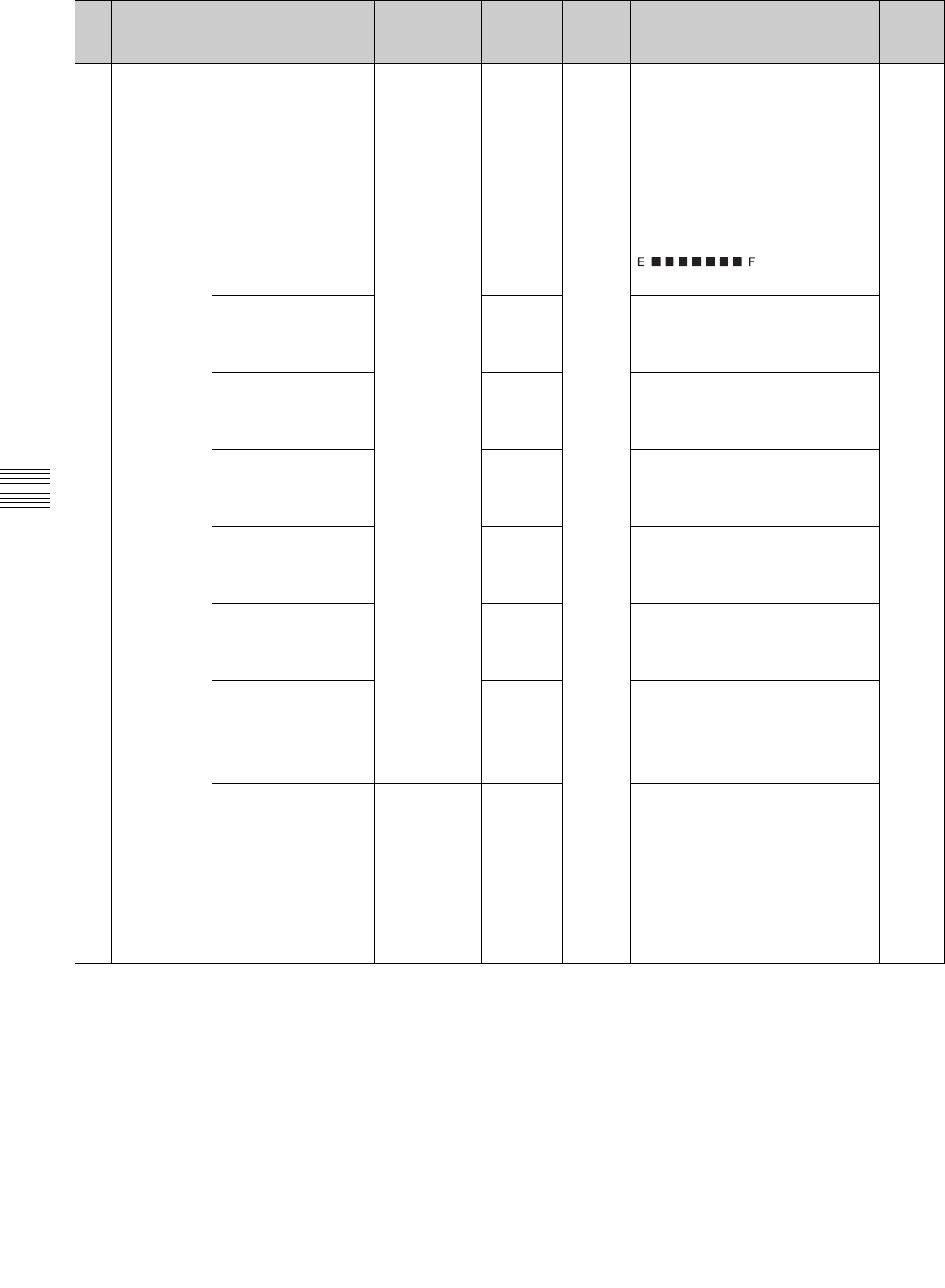
126 Menu Organization and Operation
Chapter 5 Menu Displays and Detailed Settings
08 BATTERY 2 TYPE DETECTION AUTO /
OTHER AUTO – AUTO: Automatically detects
battery type.
OTHER: Determines battery type
as always “Others”.
A
SEGMENT NO.7 11.0 to 17.0V
(in 0.1 V
steps)
17.0V When “Others” is determined,
remaining battery capacity
indicator segment 7 lights when
below the set voltage.
[Battery battery capacity indicator
segment]
SEGMENT NO.6 16.0V When “Others” is determined,
remaining battery capacity
indicator segment 6 lights when
below the set voltage.
SEGMENT NO.5 15.0V When “Others” is determined,
remaining battery capacity
indicator segment 5 lights when
below the set voltage.
SEGMENT NO.4 14.0V When “Others” is determined,
remaining battery capacity
indicator segment 4 lights when
below the set voltage.
SEGMENT NO.3 13.0V When “Others” is determined,
remaining battery capacity
indicator segment 3 lights when
below the set voltage.
SEGMENT NO.2 12.0V When “Others” is determined,
remaining battery capacity
indicator segment 2 lights when
below the set voltage.
SEGMENT NO.1 11.0V When “Others” is determined,
remaining battery capacity
indicatorsegment 1 lights when
below the set voltage.
09 GENLOCK GL H PHASE (–99 to 99) 0 –Sets horizontal phase for genlock. A
H ADVANCE 0H / 90H 0H Selects the output phase when an
SD reference signal is input.
0H: Make SD REF and HD OUT in
phase.
90H: Make the HD OUT phase
90H with offset respect to the
SD reference signal
(When an HD reference signal
is input, HD REF and HD OUT
are in phase.)
No. Page Item Settings Default USER
menu
page
Description File
1 765432
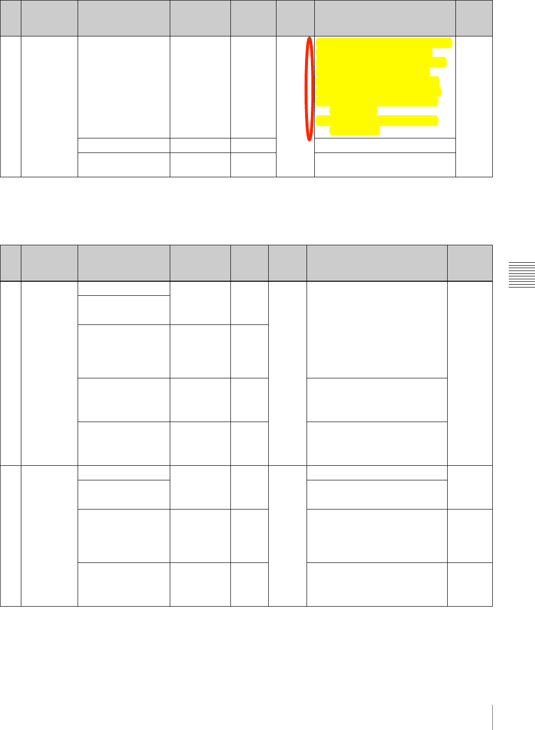
127
Menu Organization and Operation
Chapter 5 Menu Displays and Detailed Settings
1) When TYPE DETECTION on the BATTERY 2 page is set to OTHER,
this follows the setting of BEFORE END.
2) When TYPE DETECTION on the BATTERY 2 page is set to OTHER,
this follows the setting of END.
FILE menu
10 LENS ZOOM SELECT 1 / 2 1 –To control zoom from the RM-F300
Infrared Remote Commander
when a 1/2-inch lens is mounted,
set this item according to the
manufacturer of the lens (some
lenses do not require a setting).
1: Select when you are using a
Canon lens
2: Select when you are using a
Fujinon lens
A
ZOOM SPEED 0 to 99 20 Switches the zoom speed.
AF DETECT AREA FULL /
CENTER CENTER Selects the auto focus detection
area.
No. Page Item Settings Default USER
menu
page
Description File
No. Page Item Settings Default USER
menu
page
Description File
01 USER FILE USER FILE LOAD Displays the
USER FILE
selection
screen.
EXEC – C##$5C&J07'$&7.$Y,&.07'$V"#-$
+01#":$,7$%&'#$DR>;
–
USER FILE SAVE
F. ID Displays
character
input mode
(up to 16
character).
Blank
USER PRESET After asking
YES / NO,
executes the
function.
EXEC C##$5F#"#//07'$VC\F$[#7K$
C#//07'"$/,$/3#$C/&7.&-.$C#//07'":$
,7$%&'#$D@);
CUSTOMIZE RESET After asking
YES / NO,
executes the
function.
EXEC Returns the pages registered in
the USER menu to the factory
default state.
02 ALL FILE ALL FILE LOAD Displays the
FILE
selection
screen.
EXEC – Loads ALL file. –
ALL FILE SAVE Saves ALL file.
F. ID Displays
character
input mode
(up to 16
character).
Blank Names ALL file. A
ALL PRESET After asking
YES / NO,
executes the
function.
EXEC Returns items in ALL file to preset
values. –
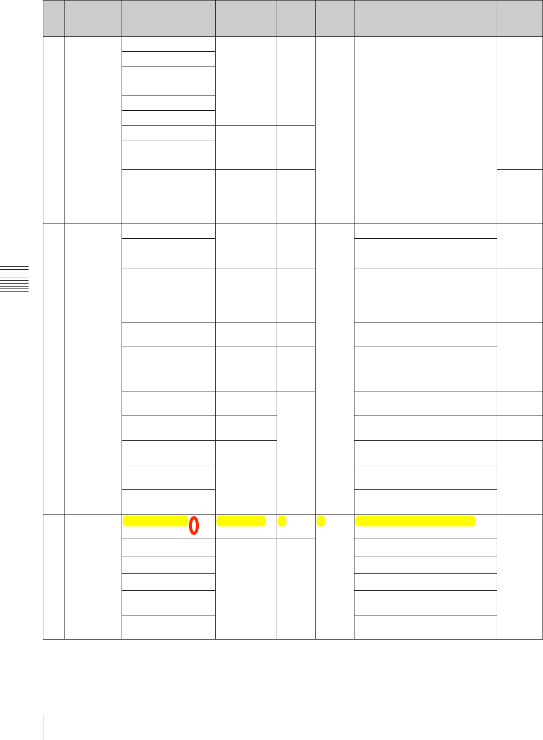
128 Menu Organization and Operation
Chapter 5 Menu Displays and Detailed Settings
03 SCENE FILE s1 –
STANDARD
–C##$5C&J07'$&7.$Y,&.07'$V"#-$
+01#":$,7$%&'#$DR>;
–
s2
s3
s4
s5
sSTANDARD
SCENE RECALL Displays the
SCENE FILE
selection
screen.
EXEC
SCENE STORE
F. ID Displays
character
input mode
(up to 16
characters).
Blank Sc
04 LENS FILE 1 LENS FILE RECALL Displays the
FILE
selection
screen.
EXEC – Loads lens file. –
LENS FILE STORE Saves lens file.
F. ID Displays
character
input mode
(up to 16
characters).
Blank Names lens file. L
SOURCE – – Displays number of selected lens
file. –
LENS NO OFFSET After asking
YES / NO,
executes the
function.
EXEC Resets the lens file to standard.
IRIS GAIN (–99 to 99) – Adjusts the response speed of the
auto iris according to the lens. L
LENS AUTO RECALL ON/OFF Selects whether to automatically
read in a lens file. A
<LENS
INFORMATION> – – –
L.ID Lens file name for connected serial
lens
L.MF Lens manufacturer for connected
serial lens
05 LENS FILE 2 LENS M VMOD (–99 ~ +99) 0 – Sets lens file V SAW shading. L
LENS R FLARE – – Adjusts lens file flare (R).
LENS G FLARE Adjusts lens file flare (G).
LENS B FLARE Adjusts lens file flare (B).
LENS W-R OFST Compensates R value when
extender and shrinker used.
LENS W-B OFST Compensates B value when
extender and shrinker used.
No. Page Item Settings Default USER
menu
page
Description File
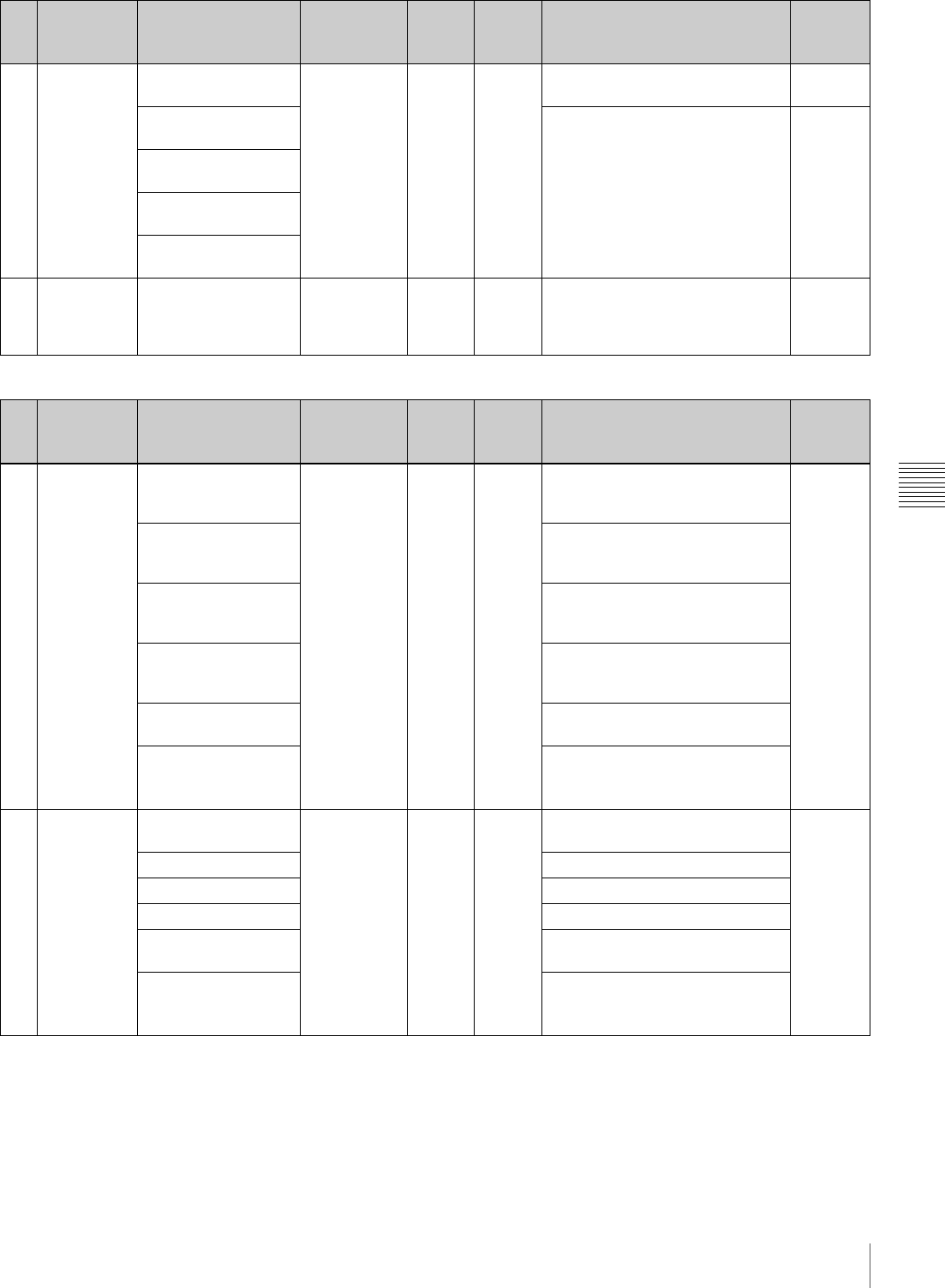
129
Menu Organization and Operation
Chapter 5 Menu Displays and Detailed Settings
DIAGNOSIS menu
06 LENS FILE 3 SHADING CH SEL R / G / B R –Selects the channel adjusted by
this menu. –
LENS R H SAW White shading correction L
LENS R H PARA
LENS R V SAW
LENS R V PARA
07 MEMORY
STICK FORMAT After asking
YES / NO,
executes the
function.
EXEC – Formats “Memory Stick”. –
No. Page Item Settings Default USER
menu
page
Description File
01 HOURS
METER OPERATION Display only – – Shows cumulative time that this
unit has been powered on, in units
of 1 hour.
–
OPERATION (rst) Shows cumulative light output
parameters of optical head
(resettable).
SPINDLE (rst) Shows cumulative total time of
spindle rotation, in units of 1 hour
(resettable).
LASER (rst) Shows cumulative light output
parameters of optical head
(resettable).
LOADING (rst) Shows cumulative count of disc
insertions (resettable).
SEEK (rst) Shows cumulative total of optical
head seek operation time, in units
of 1 hour (resettable).
02 DISC
STATUS USER ID Display only – – Shows the user ID on the disc
itself. –
TITLE Shows the title on the disc itself.
REMAIN Shows the remaining disc capacity.
REWRITE Shows number of rewrites.
SALVAGE When salvage is required, shows
“required”.
FILE SYSTEM When the file system cannot be
recognized or there is a fault,
shows “unknown”.
No. Page Item Settings Default USER
menu
page
Description File
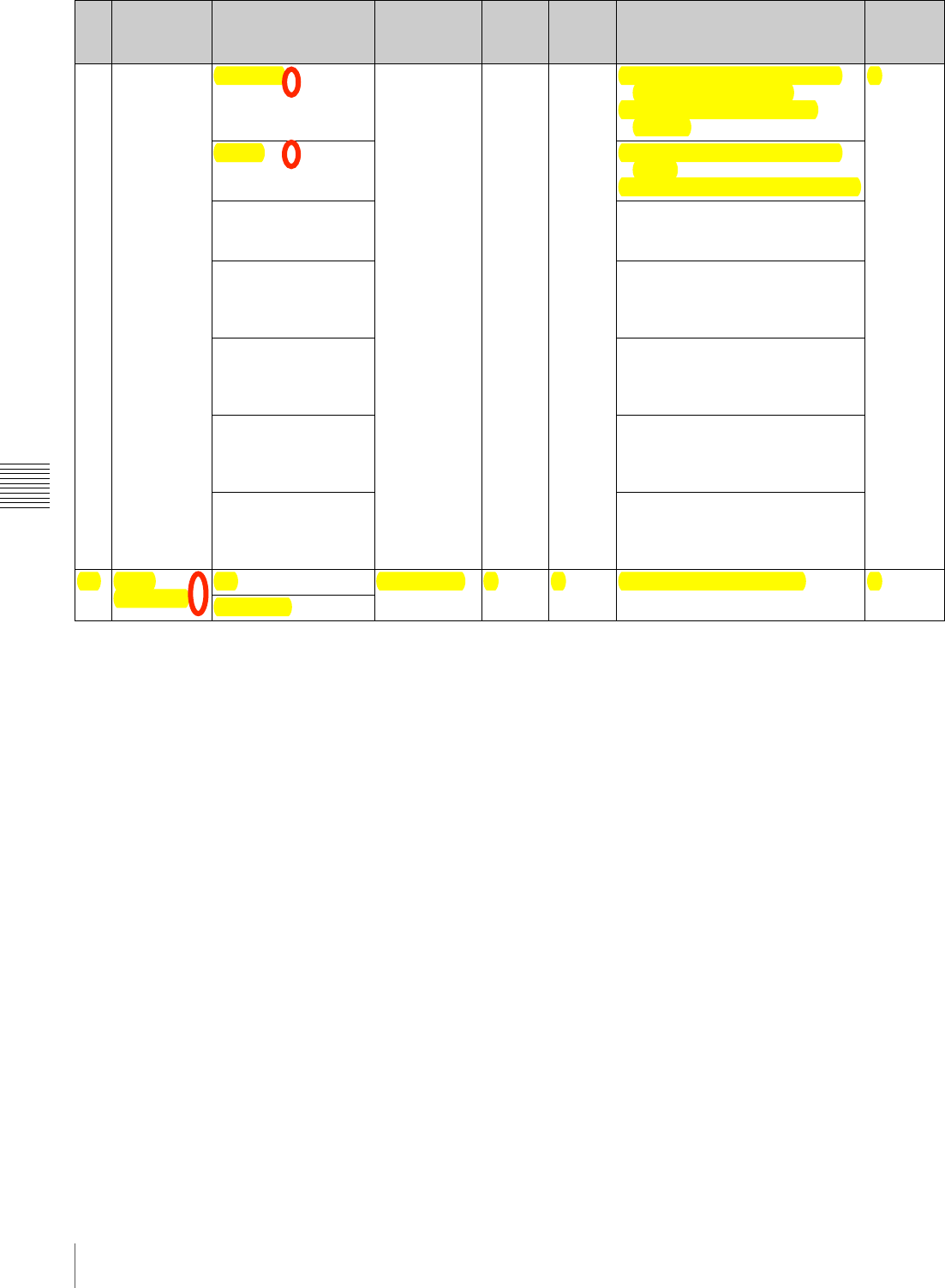
130 Menu Organization and Operation
Chapter 5 Menu Displays and Detailed Settings
03 CLIP
STATUS CLIP NO. Display only – – In NORMAL MODE: current clip
number/total clip count
In CLIP LIST MODE: clip list
number
–
NAME In NORMAL MODE: current clip
name
In CLIP LIST MODE: clip list name
TITLE In NORMAL MODE: current clip
title
In CLIP LIST MODE: clip list title
RECORD DEVICE In NORMAL MODE: name of
device on which current clip was
recorded
In CLIP LIST MODE: shows “-----”.
SERIAL In NORMAL MODE: serial number
of device on which current clip
was recorded
In CLIP LIST MODE: shows “-----”.
DATE In NORMAL MODE: date current
clip was recorded
In CLIP LIST MODE: date clip list
was created
TIME In NORMAL MODE: time current
clip was recorded
In CLIP LIST MODE: time clip list
was created
04 ROM
VERSION AT Display only – – Displays the ROM version. –
PACKAGE
No. Page Item Settings Default USER
menu
page
Description File
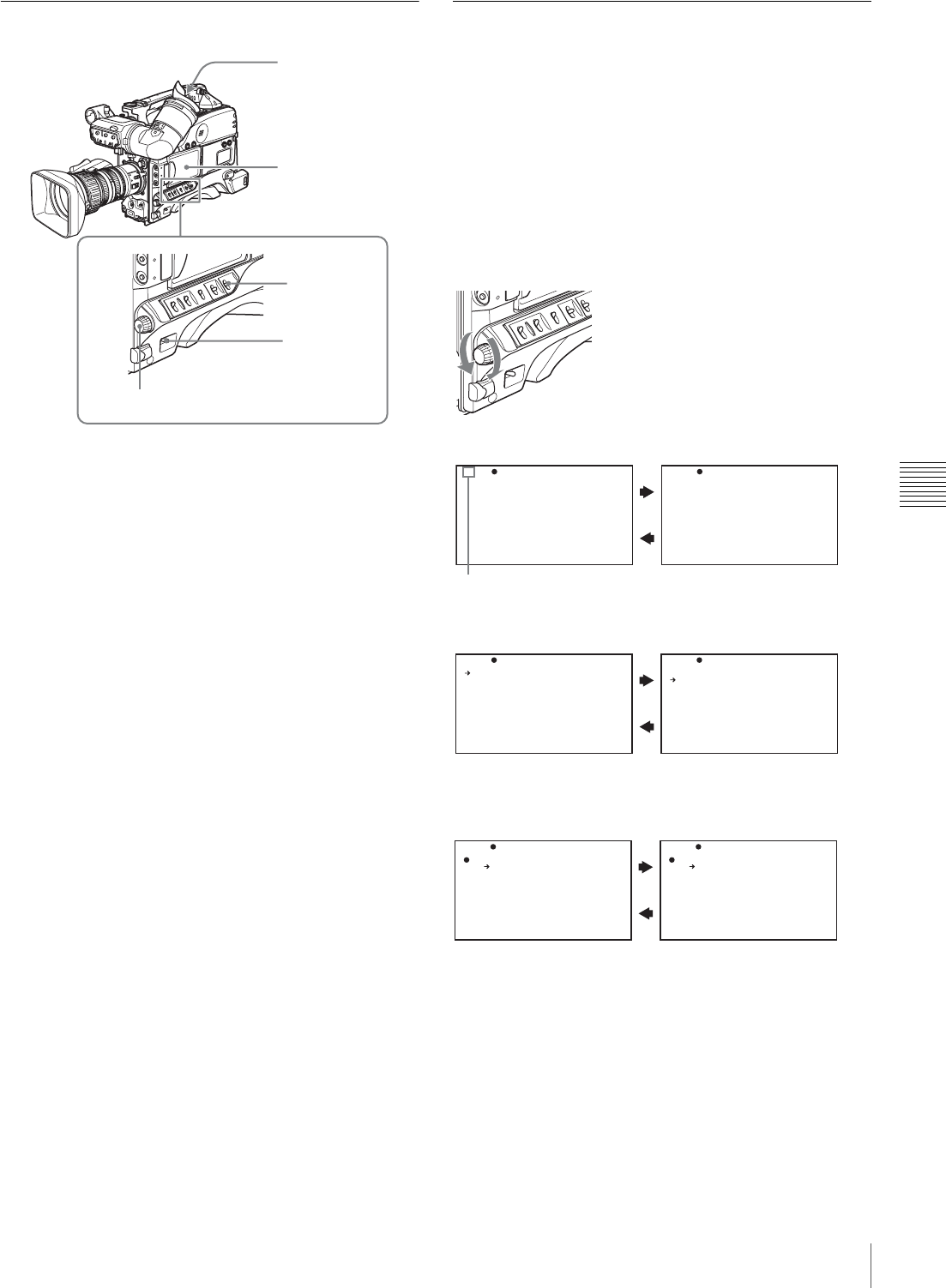
131
Menu Organization and Operation
Chapter 5 Menu Displays and Detailed Settings
Displaying Menus
When the camcorder is powered on, flick the MENU
switch to the ON position to display the menu on the
viewfinder screen and the LCD monitor.
If this is the first time the menu has been used after the
camcorder has been powered on, the USER menu is
displayed. If the menu has been used before, the last
accessed page appears.
When the menu is not displayed on the LCD
monitor
Press the DISPLAY/EXPAND button at the lower left of
the LCD monitor to select the CHAR display.
To clear the menu display from the screen
Flick the MENU switch to OFF.
When the DISPLAY switch on the viewfinder is set to ON,
the display indicating the current status of the camcorder
appears on the viewfinder screen.
For details, see “Selecting the Display Items” on page
136.
To display the TOP menu
With no menu displayed on the screen, hold down the
MENU knob and flick the MENU switch to the ON
position.
Basic Menu Operations
By pressing and turning the MENU knob, you can set
various menu items. In the remainder of this section, the
LCD monitor is generally shown as an example of the
menu display, but a similar display also appears on the
viewfinder screen.
To select the setting items and values on
the menu
Turn the MENU knob to select in the cases explained
below.
To scroll pages
To select a menu or setting item
To change a setting value
View
f
inder
MENU switch
LCD monitor
POWER switch
MENU knob
TO P? 0 8 O UT PU T
C O MPO NE NT OU T: AU TO
H D SD (P LA Y B AC K) : 16 :9
TO P? 0 9 V F SE TTI NG
Z E BRA :OF F
Z E BRA S EL ECT :1
Z E BRA 1 DE T.L EV EL :70 %
D E TAI L FR EQ :NO RM
V F AS PE CT :AU TO
When ? blinks, turn the MENU knob to switch pages.
When b appears, turn the MENU knob to move b up and down.
TO P 0 8 O UT PU T
C O MPO NE NT OU T: AU TO
H D SD (P LA Y B AC K) : 16 :9
TO P 0 8 O UT PU T
C O MPO NE NT OU T: AU TO
H D SD (P LA Y B AC K) : 16 :9
TOP 08 OUTPUT
C O MPO NE NT OU T: ? AU TO
H D SD (P LA Y B AC K) : 16 :9
TO P 0 8 OU TP UT
C O MPO NE NT OU T: ? Y Pb Pr
H D SD (P LA Y B AC K) : 16 :9
When ? blinks, turn the MENU knob to change the setting (ON/OFF,
value, etc.).
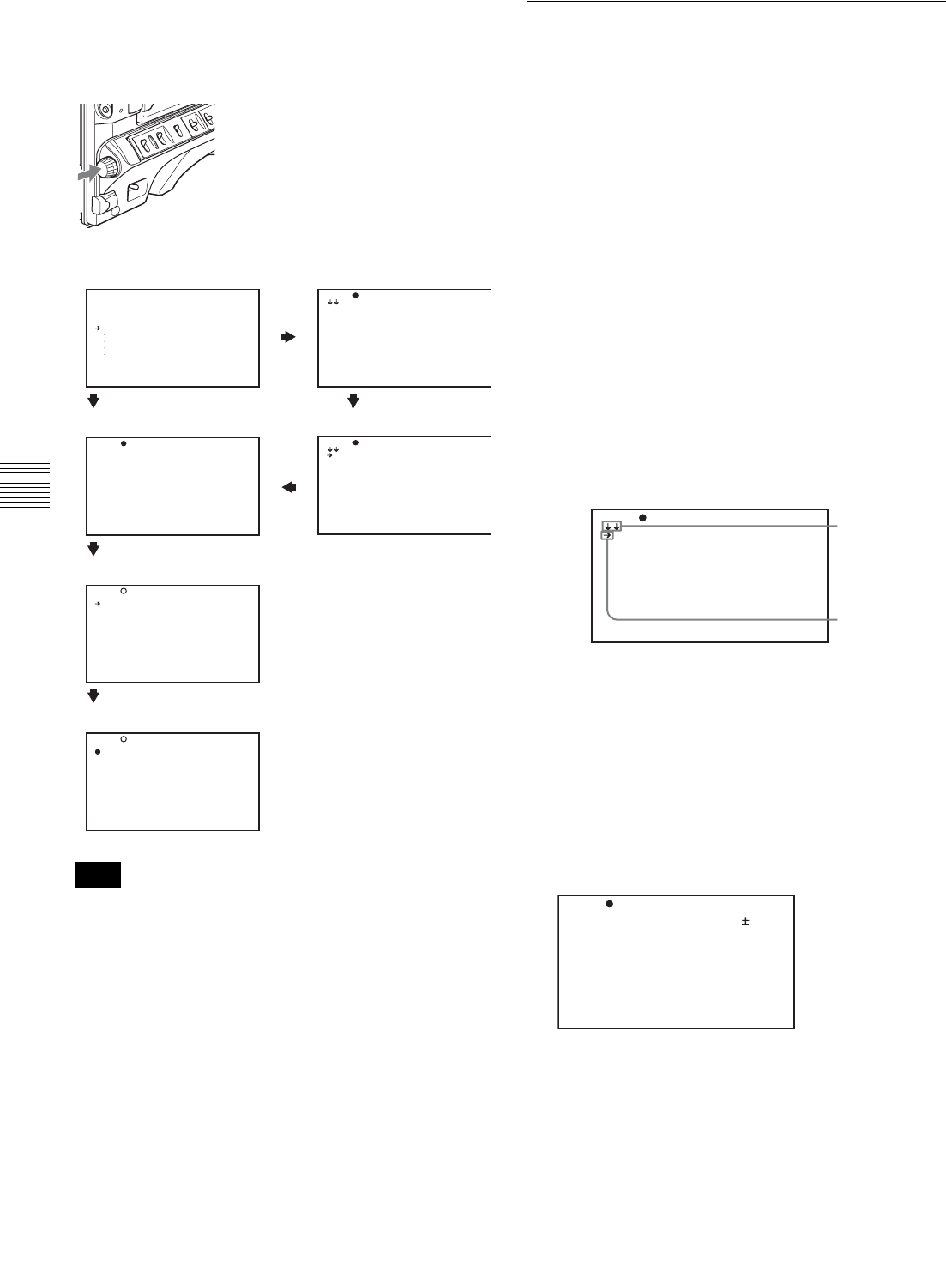
132 Menu Organization and Operation
Chapter 5 Menu Displays and Detailed Settings
To confirm the selection of a menu, a
setting item, or a setting value
Each time you press the MENU knob, the menu display
switches in the following sequence.
Example: When using the OPERATION menu
If the TOP menu has not been displayed since the
camcorder is powered on, “TOP” does not appear at the
upper right on the above screen, and you cannot go to the
TOP menu. In this case, follow the procedure in “To
display the TOP menu” on page 131.
To display the TOP menu when another menu is
displayed
Move b to “TOP” displayed at the top right of each page
of the menu, and press the MENU knob. Or push the
MENU switch repeatedly to ON until the TOP menu is
displayed.
Using the USER Menu (Example
Menu Operation)
This section explains menu operations using the USER
menu as an example. The operations are the same for the
ALL, OPERATION, PAINT, MAINTENANCE, FILE,
and DIAGNOSIS menus. For details about how to operate
the USER MENU CUSTOMIZE menu, see “Editing the
USER Menu” on page 133.
1
Flick the MENU switch to ON.
Normally, the USER menu appears.
If it does not, turn the MENU knob to move b to
USER in the TOP menu, and press the MENU knob.
If the USER menu has been used before, the last
accessed page appears. In this case, go to step 2.
If this is the first time the USER menu has been
displayed, the CONTENTS page of the USER menu
appears. In this case, follow the procedure below.
1Press the MENU knob. Then turn the MENU knob
to move b to the desired page number.
2Press the MENU knob again.
The page selected in 1 is displayed. Go to step 3.
When you set items on the ALL, OPERATION,
PAINT, MAINTENANCE, FILE, or DIAGNOSIS
menu, move b to the menu that contains the desired
item in the TOP menu, and then press the MENU
knob.
2
Turn the MENU knob until the desired page appears.
3
Press the MENU knob.
b and z appear.
Note
< T OP ME N U>
USER
U S ER M EN U C U STO M IZE
ALL
O PER A TI ON
PAINT
M AIN T EN ANC E
FILE
D IAG N OS IS
TO P? 0 0 C O NTE N TS
0 1 .FO R MAT
0 2 .SP E CIA L E FFE C TS
0 3 .AS S IGN A BL E
0 4 .DI S C
0 5 .CL I P T I TL E
0 6 .GA I N S W
0 7 .EZ MOD E / TL C S
0 8 .OF F SET WH ITE
0 9 .OU T PUT
1 0 .VI D EO O UT
TO P 0 0 CO N TE NTS
0 1 .FO R MAT
0 2 .SP E CIA L E FFE C TS
0 3 .AS S IGN A BL E
0 4 .DI S C
0 5 .CL I P T I TL E
0 6 .GA I N S W
0 7 .EZ MOD E / TL C S
0 8 .OF F SET WH ITE
0 9 .OU T PUT
1 0 .VI D EO O UT
TO P 0 9 O U TPU T
C O MPO N EN T O U T: A UTO
H D SD ( PL AY B ACK ) : 1 6:9
TO P? 0 9 O U TPU T
C O MPO N EN T O U T: A UTO
H D SD ( PL AY B ACK ) : 1 6:9
TO P 0 9 OU T PUT
C O MPO N EN T O U T: ? A UTO
H D SD ( PL AY B ACK ) : 1 6:9
TOP menu
If the menu has been
used before
Menu selection page
If the menu
has not
been used
Setting value selection mode
Setting item selection mode
CONTENTS page
Menu selection mode
TO PU0 0 CON TE NT S
01.PAINT
0 2.SCE NE F ILE
03.FORMAT
04.SPECIAL EFFECTS
0 5.ASS IG NA BLE
06.DISC
07.OUTPUT
0 8.VF SE TT ING
09.MARKER
0
This indicates
that the menu
screen can be
scrolled.
b
TOP?U01 PAINT
A .IRIS : 0
D ETAIL L EV EL : 0
M ASTER B LA CK : 0
GAMMA SELECT : STD
MASTER BLK GAMMA: 0
B LACK GA MM A : O FF
P RESET M TX SEL : S TD
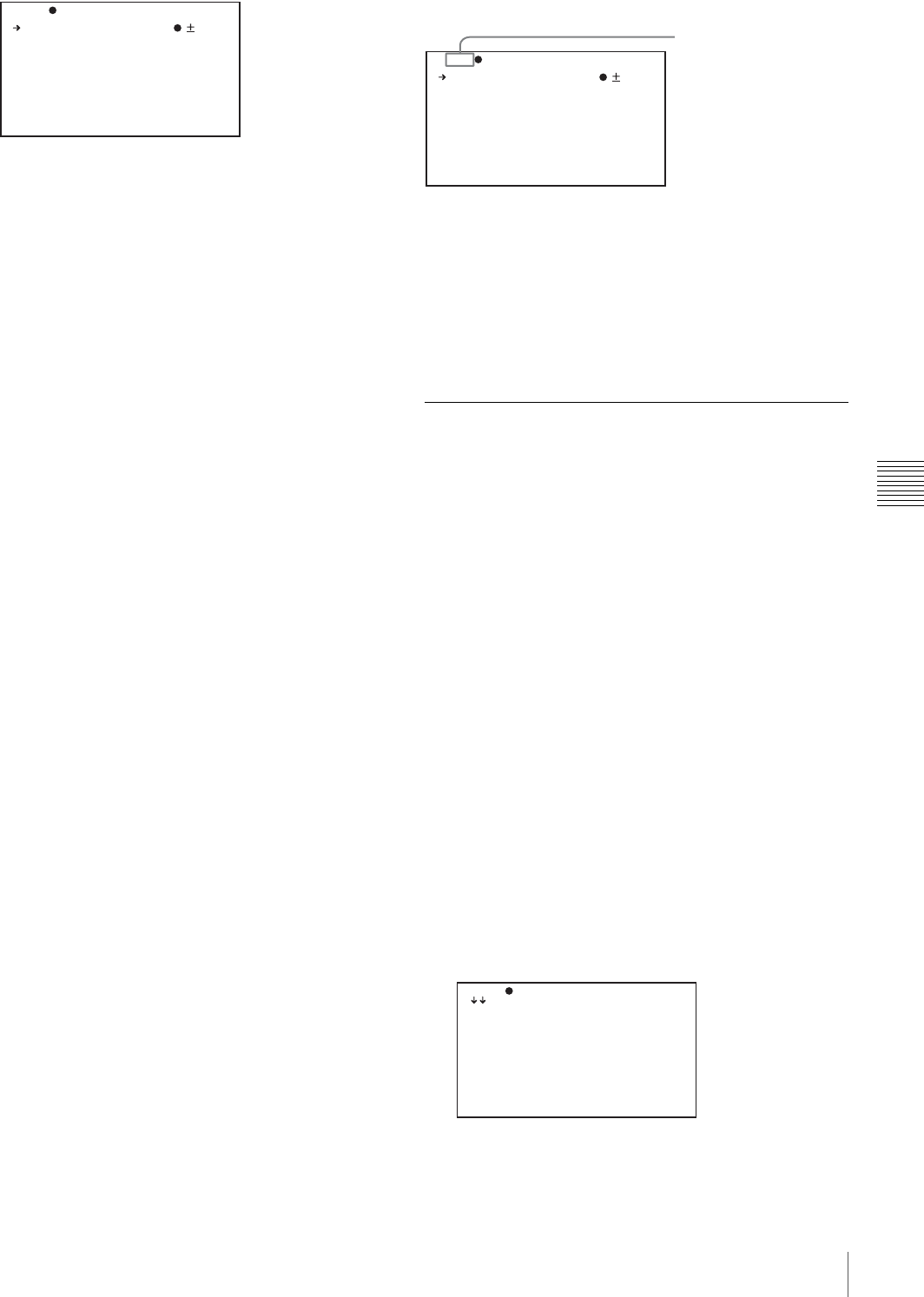
133
Menu Organization and Operation
Chapter 5 Menu Displays and Detailed Settings
4
Turn the MENU knob to move b to the desired item,
and then press the MENU knob.
b changes to z, and z changes to ?.
5
Turn the MENU knob to change the setting.
Depending on the direction of turning the knob, the
setting value increases, decreases, switches between
ON and OFF, and so on.
If you want to cancel a change or return to the standard
settings, see the items below “To interrupt changing
the settings” and “To return to the factory default
settings”.
To interrupt changing the settings
Flick the MENU switch to OFF.
By flicking the MENU switch to ON again, the values
that were displayed when you interrupted the setting
operations will reappear so you can continue making
settings.
6
Press the MENU knob.
z changes to b, and ? changes to z. The selection is
confirmed.
7
To continue setting other items on the same page,
repeat steps from 4 to 6.
8
To end the menu operation, flick the MENU switch to
OFF.
The menu disappears from the screen, and the display
indicating the current status of the camcorder appears
along the top and bottom of the screen.
To return to the factory default settings
By pressing and holding the MENU knob in step 5 of the
above procedure, the settings return to the factory default
values.
To move to another page
When ? appears in front of the page number
Turn the MENU knob to switch pages.
When nothing appears in front of the page
number
Turn the MENU knob to move b to the page number, and
press the MENU knob. Then turn the MENU knob to
switch pages.
Editing the USER Menu
The USER MENU CUSTOMIZE menu allows you to
configure a USER menu that consists only of pages and
items that you need by adding, deleting or replacing the
pages.
To add a new page
The USER MENU CUSTOMIZE menu allows you to add
a new page to the USER menu.
While the EDIT page contains factory-preset items, the
USER 9 EDIT to USER 19 EDIT pages are all blank in
their initial state. You can register up to 10 items, including
blank lines, on each of these pages.
(How to select an item in the menu screen: Turn the
MENU knob to move the b mark to the desired item.)
1
Display the TOP menu (see page 131).
2
Select USER MENU CUSTOMIZE, and press the
MENU knob.
If this is the first time the USER MENU CUSTOMIZE
menu has been displayed, the CONTENTS page of the
menu appears.
If the USER MENU CUSTOMIZE menu has been
used before, the last accessed page appears.
TO P U 01 PA IN T
A .IRIS : 0
D ETAIL L EV EL : 0
M ASTER B LA CK : 0
G AMMA SE LE CT : S TD
M ASTER B LK GAMM A: 0
B LACK GA MM A : O FF
P RESET M TX SEL : S TD
TOP?U01 PAINT
A.IRIS : 0
DETAIL LEVEL : 0
MASTER BLACK : 0
GAMMA SELECT : STD
MASTER BLK GAMMA: 0
BLACK GAMMA : OFF
PRESET MTX SEL : STD
Page number
TOP?E00 CONTENTS
01.EDIT PAGE
0 2.USE R 1 ED IT
0 3.USE R 2 ED IT
0 4.USE R 3 ED IT
0 5.USE R 4 ED IT
0 6.USE R 5 ED IT
0 7.USE R 6 ED IT
0 8.USE R 7 ED IT
0 9.USE R 8 ED IT
1 0.USE R 9 ED IT

134 Menu Organization and Operation
Chapter 5 Menu Displays and Detailed Settings
3
If the CONTENTS page is displayed, press the MENU
knob. Then select one of USER 1 EDIT to USER 19
EDIT, and press the MENU knob.
If a different page is displayed, turn the MENU knob
until the desired page appears, then press the MENU
knob.
4
Press the MENU knob. Then select the line where you
want to add an item, and press the MENU knob.
The EDIT FUNCTION page appears.
5
Press the MENU knob. Then select INSERT, and
press the MENU knob.
The page for the last added item appears.
6
Add the items as follows.
1Turn the MENU knob until the page that contains
the desired items appears, then press the MENU
knob.
2Select the desired item, and press the MENU
knob.
The USER 9 EDIT page appears again, displaying the
newly added item.
7
Repeat steps 4 to 6 to add the remaining items.
You can add up to 10 items on one page.
To delete items from a page by using the MENU
knob
1
Follow steps 1 to 3 in “To add a new page” on page
133.
2
Press the MENU knob. Then select the item that you
wan to delete, and press and hold the MENU knob.
The item is deleted.
To delete items from a page by using the EDIT
FUNCTION page
1
Follow steps 1 to 3 in “To add a new page” on page
133.
2
Press the MENU knob. Then select the item that you
want to delete, and press the MENU knob.
The EDIT FUNCTION page appears.
3
Select DELETE, and press the MENU knob.
The previously displayed page appears again, and the
message “DELETE OK? YES b NO” appears at the
upper right.
4
To delete, select YES, and press the MENU knob.
To replace items on a page
1
Follow steps 1 to 3 in “To add a new page” on page
133.
2
Press the MENU knob. Then select the item that you
want to replace, and press the MENU knob.
The EDIT FUNCTION page appears.
3
Select MOVE, and press the MENU knob.
The previously displayed page appears again.
4
Select the position to which you want to move the
item, and press the MENU knob.
The item selected in step 2 moves to the position that
you selected in step 4.
To insert a blank line
1
Follow steps 1 to 3 in “To add a new page” on page
133.
2
Press the MENU knob. Then select the item above
which you want to insert a blank line, and press the
MENU knob.
The EDIT FUNCTION page appears.
3
Select BLANK, and press the MENU knob.
The previously displayed page appears again, and a
blank line is inserted above the specified item.
You cannot insert a blank line on a page where 10 items
have already been registered.
TO P E 10 US ER 9 EDIT
Example: When the USER 9 EDIT page is selected
ES C ED IT F UNCTI ON
INSERT
MOVE
DELETE
BLANK
Note
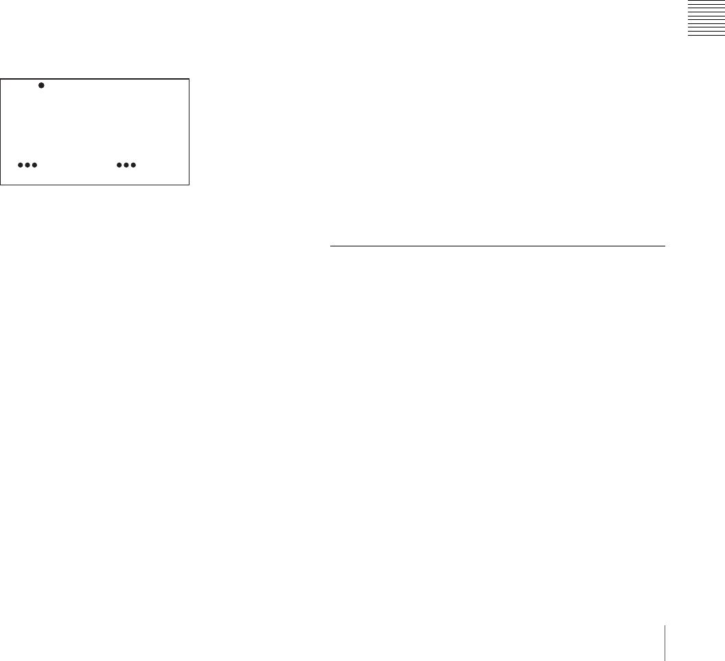
135
Menu Organization and Operation
Chapter 5 Menu Displays and Detailed Settings
To add/delete/replace pages
You can add a new page to the USER menu, delete a page
from the USER menu, or replace pages, using the EDIT
PAGE of the USER MENU CUSTOMIZE menu.
To add a page
(How to select an item in the menu screen: Turn the
MENU knob to move the b mark to the desired item.)
1
Display the TOP menu (see page 131).
2
Select USER MENU CUSTOMIZE, and press the
MENU knob.
If this is the first time the USER MENU CUSTOMIZE
menu has been displayed, the CONTENTS page
appears. If the menu has been used before, the last
accessed page appears.
3
If the CONTENTS page is displayed, press the MENU
knob. Then select EDIT PAGE, and press the MENU
knob.
If a different page is displayed, turn the MENU knob
until the EDIT PAGE screen appears.
The EDIT PAGE appears.
4
Press the MENU knob. Then select the position where
you want to add the page, and press the MENU knob.
The EDIT FUNCTION page appears.
5
Select INSERT, and press the MENU knob.
The CONTENTS page appears.
6
Select the desired page, and press the MENU knob.
The number and name of the page selected in step 6 is
added above the item selected in step 4.
To cancel adding a page
Before pressing the MENU knob in step 6, select ESC
at the top right of the screen, and press the MENU
knob.
The EDIT PAGE screen appears again.
To delete a page by using the MENU knob
1
Follow steps 1 to 3 in “To add a page”.
2
Press the MENU knob. Then select the page that you
want to delete, and hold down the MENU knob.
To delete a page by using the EDIT FUNCTION
page
1
Follow steps 1 to 3 in “To add a page”.
2
Press the MENU knob. Then select the page that you
want to delete, and press the MENU knob.
The EDIT FUNCTION page appears.
3
Select DELETE, and press the MENU knob.
The previously displayed page appears again, and the
message “DELETE OK? YES b NO” appears at the
upper right.
4
Select YES, and press the MENU knob.
To replace a page
1
Follow steps 1 to 3 in “To add a page”.
2
Press the MENU knob. Then select the page that you
want to move, and press the MENU knob.
The EDIT FUNCTION page appears.
3
Select MOVE, and press the MENU knob.
The previous screen appears again.
4
Select the position to which you want to move the page
selected in step 2, and press the MENU knob.
The page is moved to the position selected in step 4.
Resetting USER Menu Settings to
the Standard Settings
You can return all settings in the USER menu to the
standard settings.
(How to select an item in the menu screen: Turn the
MENU knob to move the b mark to the desired item.)
1
Display the USER FILE page of the FILE menu, and
press the MENU knob.
For details on menu operations, see “Basic Menu
Operations” on page 131.
0 1.PAI NT
0 2.FOR MA T
0 3.OUT PU T
0 4.ASS IG NA BLE
0 5.SPE CI AL @EFFEC TS
0 6.VF SE TT ING
0 7.SKI N DE TAIL
0 8.SCE NE F ILE
0 9.RES ET
END O F PAGE
TO P?E 01 ED IT P AGE
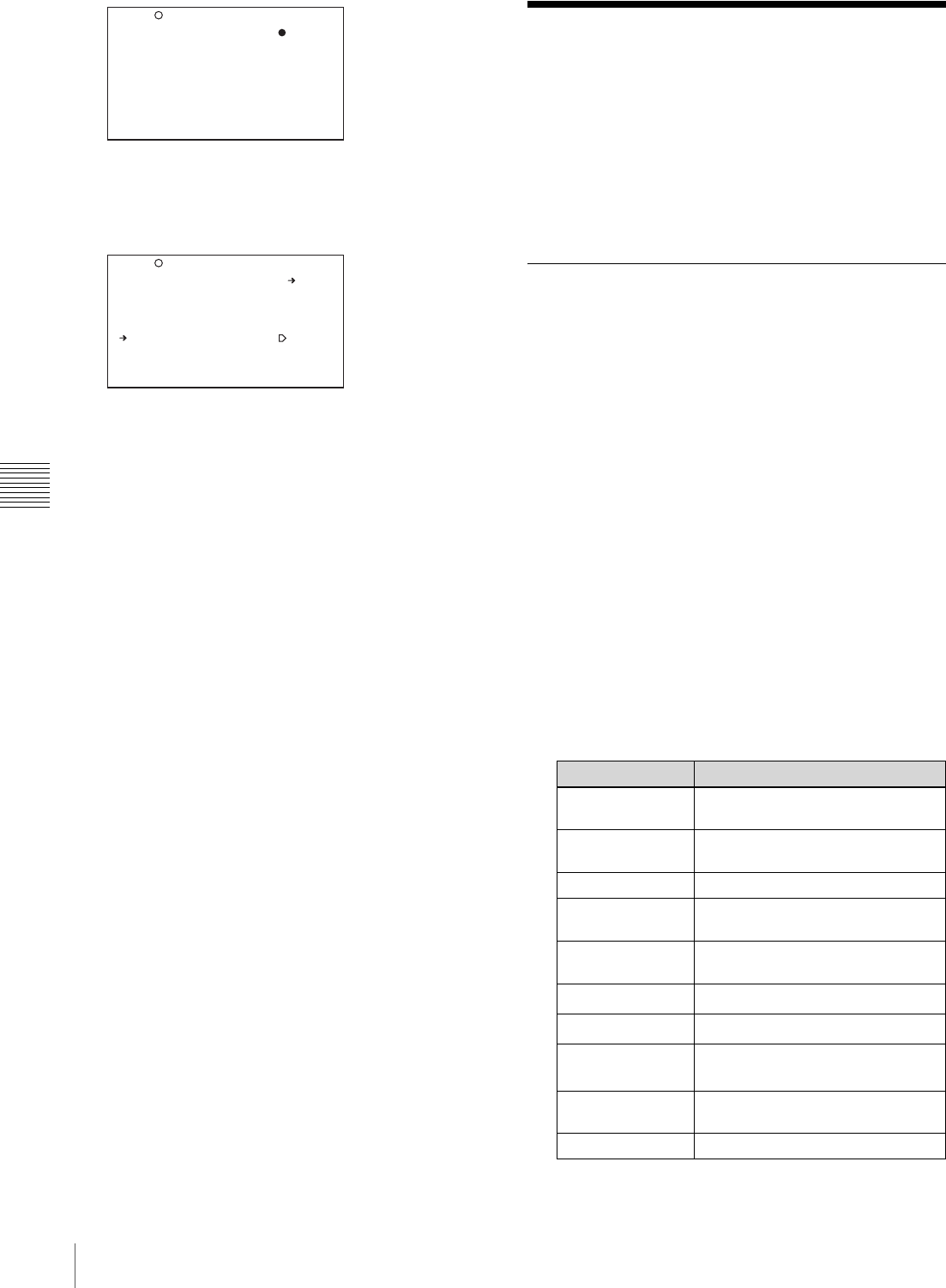
136 Setting the Status Display on the Viewfinder Screen and the LCD Monitor
Chapter 5 Menu Displays and Detailed Settings
2
Press the MENU knob, then select USER PRESET,
and press the MENU knob.
The message “PRESET OK? YES b NO” appears.
3
Select YES, and press the MENU knob.
The settings for all items in the USER menu are reset
to the standard settings.
Setting the Status Display
on the Viewfinder Screen
and the LCD Monitor
This section explains the menu settings for the display of
the viewfinder screen. These settings are also used for the
display of the LCD monitor in the same way.
Selecting the Display Items
To select the items to be displayed on the viewfinder
screen (with the viewfinder DISPLAY set to ON) and the
LCD monitor, use the VF DISP 1 and VF DISP 2 pages of
the OPERATION menu.
(How to select an item in the menu screen: Turn the
MENU knob to move the b mark to the desired item.)
1
Display the VF DISP 1 or VF DISP 2 page of the
OPERATION menu, and press the MENU knob.
For details on menu operations, see “Basic Menu
Operations” on page 131.
2
Select the desired setting item, and press the MENU
knob.
On the VF DISP 1 and VF DISP 2 pages, you can
select the following items to be displayed on the
screen.
VF DISP 1 page
1) This item may not appear depending on the mounted lens.
TO P?F 01 US ER F ILE
U SER F IL E LOAD : EX EC
U SER F IL E SAVE : EX EC
F .ID :
sssssssssssssssss
U SER P RE SE T : EX EC
C USTOM IZ E RESET : EX EC
TO P?F 01 US ER F ILE
PRES ET O K? YE S NO
U SER F IL E LOAD : EX EC
U SER F IL E SAVE : EX EC
F .ID :
sssssssssssssssss
U SER P RE SE T : EX EC
C USTOM IZ E RESET : EX EC
Item Description
DISP REC
FORMAT Displays the recording format.
DISP BIT RATE Indication of HQ, SP or LP
recording.
DISP SYSTEM System frequency
DISP FRAME
RATE Indication of frame rate during slow
& quick-motion recording.
DISP 16:9 Aspect ratio indication when
recording SD signals
DISP ZOOM1) Zoom position indication
DISP FOCUS1) Focus setting
DISP BATT
REMAIN2)
Displays the battery voltage or
battery remaining capacity.
DISP REC/PLAY REC, PLAY, F REV, and F FWD
indications
DISP TIME CODE Displays the timecode.

137
Setting the Status Display on the Viewfinder Screen and the LCD Monitor
Chapter 5 Menu Displays and Detailed Settings
2) When an Anton Bauer battery system or a BP-GL65/GL95 battery
pack is installed, the remaining battery power is shown as a
percentage value (%) according to the setting of this item.
INT: When one of the above batteries is installed, the remaining
power is shown as a percentage value (%) when there is a change in
the value or when the power is low.
AUTO: The remaining power is shown as a percentage value (%)
when one of the above batteries is installed. Otherwise the voltage
(VOLT) is displayed continuously.
VOLT: The voltage (VOLT) is displayed continuously.
VF DISP 2 page
3
Turn the MENU knob to select the desired setting, and
press the MENU knob.
4
Repeat steps 2 and 3 until you have set all of the
desired items.
Change Confirmation/Adjustment
Progress Messages
The messages indicating setting changes, progress and
consequence of adjustments, and the situations indicated
by these messages are as follows.
Setting change confirmation/adjustment progress
messages
1) The corresponding message is also displayed for about 3 seconds when the
SHUTTER switch is set to ON.
Setting the Marker Display
You can switch the display of the center and safety zone
markers on or off and select whether the area indicated by
the safety zone marker is 80%, 90%, 92.5%, or 95% of the
screen area.
(How to select an item in the menu screen: Turn the
MENU knob to move the b mark to the desired item.)
1
Display the MARKER page of the USER (or
OPERATION) menu, and press the MENU knob.
For details on menu operations, see “Basic Menu
Operations” on page 131.
2
Select the desired setting item, and press the MENU
knob.
You can set the following items on the MARKER
page.
3
Turn the MENU knob to select the desired setting, and
press the MENU knob.
4
Repeat steps 3 and 4 until you have set all of the
desired items.
Item Description
DISP 5600K Displays “5600K”.
DISP FILTER Displays types of the ND filter.
DISP WHITE Displays selected white balance
memory.
DISP GAIN Displays gain value.
DISP SHUTTER Displays shutter speed and ECS
mode.
DISP AUDIO Displays audio level.
DISP DISC Displays remaining disc capacity.
DISP IRIS Lens iris setting indication
DISP LOW LIGHT “LOW LIGHT” indication when the
average video level is below a
certain threshold.
DISP INTERVAL “INTERVAL TIME” indication
during interval recording.
Situation Message to appear
The filter selection has been
changed FILTER: n
(where n = 1, 2, 3, 4)
The gain setting has been
changed GAIN: n
(where n = –3dB, 0dB, 3dB,
6dB, 9dB,12dB, 18dB, 24dB,
30dB, 36dB, 42dB, 48dB)
The setting of the WHITE
BAL switch has been
changed
WHITE: n
(where n = A CH, B CH,
PRESET) or ATW: RUN
The OUTPUT/DCC switches
has been set to DCC ON or
OFF
DCC: ON (or OFF)
The shutter speed and mode
setting has been changed 1)
: SHUTTER: 1/100 (or 1/125,
1/250, 1/500, 1/1000, 1/2000,
ECS, SLS)
The black or white balance
has been adjusted E.g. WHITE: OK
Item Description
MARKER If you want no markers to be
displayed, set to OFF.
CENTER To display the center marker, set
to ON.
SAFETY ZONE To display the safety zone, set to
ON.
SAFETY AREA Selects the safety zone area.
ASPECT To display the aspect marker, set
to ON.
ASPECT SELECT Selects the type of the aspect
marker. (14:9/13:9/4:3)
Situation Message to appear
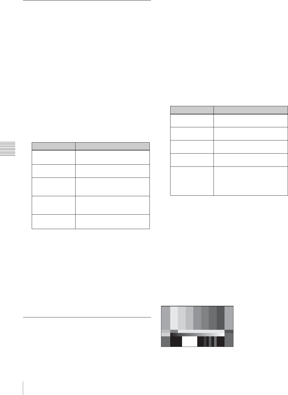
138 Setting the Status Display on the Viewfinder Screen and the LCD Monitor
Chapter 5 Menu Displays and Detailed Settings
Setting the Viewfinder Screen
Display
You can make settings for viewfinder screen display
functions (zebra display, VF detail function, and aspect
ratio).
(How to select an item in the menu screen: Turn the
MENU knob to move the b mark to the desired item.)
1
Display the VF SETTING page of the USER
(OPERATION) menu, and press the MENU knob.
For details on menu operations, see “Basic Menu
Operations” on page 131.
2
Select the desired setting item, and press the MENU
knob.
You can set the following items on the VF SETTING
page.
1) When you use the viewfinder which is not equipped with a ZEBRA
switch, turns the display on or off using this item. When you use the
viewfinder with a ZEBRA switch, the switch operation and the
operation of this menu are both effective (the most recent operation
prevails).
2) When the VF ASPECT item is set to AUTO, this is linked to the
setting of the “ASPECT RATIO (DV)” item on the FORMAT page.
3
Turn the MENU knob to select the desired setting, and
press the MENU knob.
4
Repeat steps 2 and 3 until you have set all of the
desired items.
Recording Shot Data Superimposed
on the Color Bars
You can select which shot data is recorded superimposed
on the color bars. You can also select which of the shot IDs
(1 to 4) set on the SHOT ID page is recorded superimposed
on the picture.
(How to select an item in the menu screen: Turn the
MENU knob to move the b mark to the desired item.)
1
Display the SHOT DISP page of the OPERATION
menu, and press the MENU knob.
For details on menu operations, see “Basic Menu
Operations” on page 131.
2
Select the desired setting item, and press the MENU
knob.
You can set the following items on the SHOT DISP
page.
3
Turn the MENU knob to select the desired setting, and
press the MENU knob.
4
Repeat steps 2 and 3 until you have set all of the
desired items.
To carry out superimposed recording
To actually record the items selected for superimposed
recording on the SHOT DISP page, set the OUTPUT/DCC
switch to BARS, DCC OFF. The items selected for
superimposed recording appear on the screen and are
recorded superimposed on the color bars.
(Display example: shows case where SHOT DATE is
ON.)
Item Description
ZEBRA Turns the zebra display ON or
OFF. 1)
ZEBRA SELECT Selects ZEBRA 1, ZEBRA 2 or
BOTH.
ZEBRA 1 DET. LVL Adjusts the level of the ZEBRA 1
display (30% to 107%). (Factory
default setting is 70%.)
DETAIL FREQ Turns the VF detail function on or
off and adjusts the level. (NORM/
HIGH)
VF ASPECT Selects the viewfinder aspect ratio
(AUTO/4:3). 2)
Item Description
SHOT DATE Selects whether or not the shot
data is superimposed.
DATE MODE Selects the date display format.
(One of Y/M/D, M/D/Y, and D/M/Y)
SHOT TIME Selects whether or not shot time
is superimposed.
TIME MODE Switching time indications to the
12-hour or 24-hour clock
SHOT ID SEL Selects whether or not the shot ID
set on the SHOT ID page is
superimposed. To carry out
superimposed recording, select
the SHOT ID number (1 to 4).
G GBRMGCYW
BW
06/03 /1 5
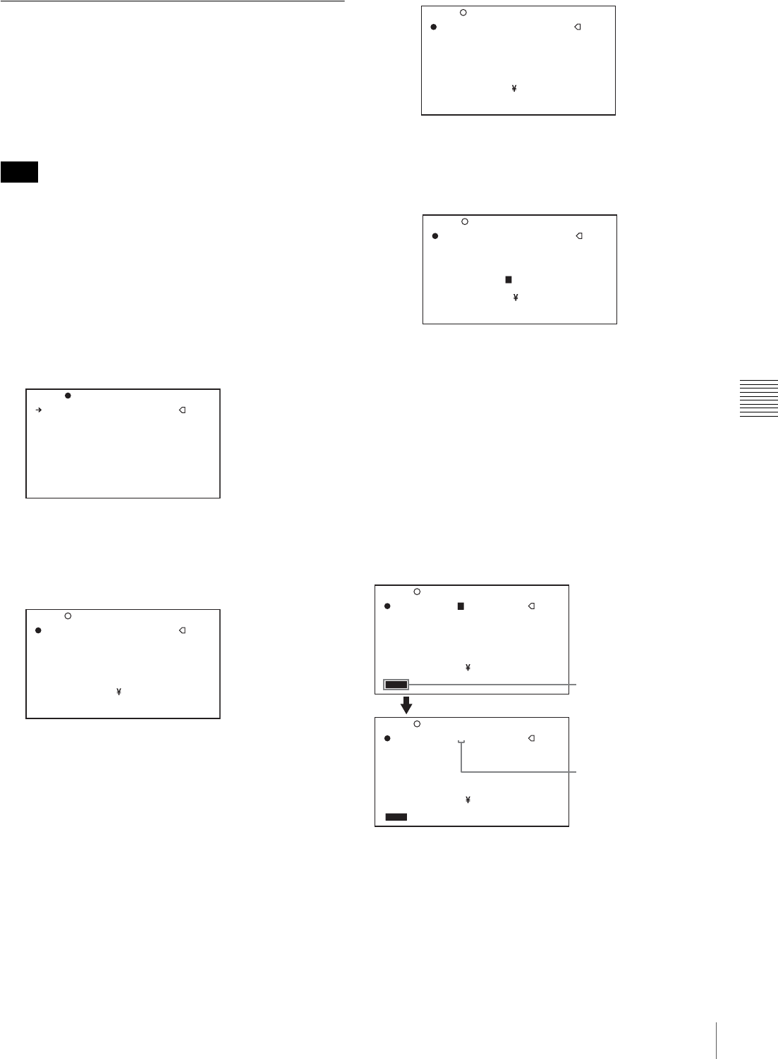
139
Setting the Status Display on the Viewfinder Screen and the LCD Monitor
Chapter 5 Menu Displays and Detailed Settings
Setting the Shot ID
You can set a shot ID of up to 12 alphanumeric characters,
spaces, and symbols. When the OUTPUT/DCC switch is
set to BARS, DCC OFF, this shot ID is output with the
color bar signal. Four shot IDs are available, ID-1 to ID-4,
and you can select the shot ID to be recorded superimposed
on the color bars.
When the menu is displayed, the shot ID is not displayed
even if the color bar signal is output.
(How to select an item in the menu screen: Turn the
MENU knob to move the b mark to the desired item.)
1
Display the SHOT ID page of the OPERATION menu,
and press the MENU knob.
For details on menu operations, see “Basic Menu
Operations” on page 131.
2
Select the ID (one of ID-1 to ID-4) you want to set, and
press the MENU knob.
x appears over the first character position in the
string, and characters can now be input.
3
Enter or change the characters.
When you are entering the shot ID for the first time, go
to step 2.
1Turn the MENU knob to move x to the character
which you want to change, then press the MENU
knob.
2Turn the MENU knob until x moves to the
character position that you want to select, then
press the MENU knob.
4
Repeat step 3 for each of the remaining characters.
5
When you have finished character inputting, turn the
MENU knob to move x over END, then press the
MENU knob.
This exits the character input mode, and returns to the
SHOT ID page.
To insert a space
In step 3 above, move x over INS, and press the MENU
knob. To cancel inserting a space, move x to RET, and
press the MENU knob.
To delete a character
In step 3 of “Setting the Shot ID” on page 139, move x
over DEL, and press the MENU knob. This deletes the
character under x in the shot ID row.
To cancel deleting the character, move x over RET, and
press the MENU knob.
Note
TO P? 13 SH OT I D
I D-1 : ?
x
I D-2 :
ss sssssssss s
I D-3 :
ss sssssssss s
I D-4 :
ss sssssssss s
I D-1 : ?
x
I D-2 :
ss sssssssss s
I D-3 :
ss sssssssss s
I D-4 :
ss sssssssss s
! #$%&' () *+ ,-./0 12 34 56 78
9: ;<=>? @A BC DEFGH IJ KL MN OP
QR STUVW XY Z[ ]abc de fg hi jk
lm nopqr st uv wxyz~
IN S DEL R ET ES C END
TO P 13 SH OT I D
ID-1 :?
x
I D-2 :
ss sssssssss s
I D-3 :
ss sssssssss s
I D-4 :
ss sssssssss s
! #$%&' () *+ ,-./0 12 34 56 78
9: ;<=>? @A BC DEFGH IJ KL MN OP
QR STUVW XY Z[ ]abc de fg hi jk
lm nopqr st uv wxyz~
IN S DEL R ET ES C END
TOP 13 SHOT ID
I D-1 : ?+
I D-2 :
ssssssssssss
I D-3 :
ssssssssssss
I D-4 :
ssssssssssss
! #$%&' () *+,-./012345678
9:;<=>?@ABCDEFGHIJKLMNOP
QRSTUVWXYZ[ ]abcdefghijk
lm nopqr st uv wxyz~
INS DEL RET ESC END
TOP 13 SHOT ID
Example: When entering the letter “+”
I D-1 : C M01 5
I D-2 :
ssssssssssss
ID-3 :
ssssssssssss
ID-4 :
ssssssssssss
! #$%&' () *+ ,-./0 12 34 56 78
9: ;<=>? @A BC DEFGH IJ KL MN OP
QR STUVW XY Z[ ]abc de fg hi jk
lm nopqr st uv wxyz~
INS D EL RE T E SC E ND
TO P 13 SH OT I D
I D-1 : C M 1 5
I D-2 :
ssssssssssss
ID-3 :
ssssssssssss
ID-4 :
ssssssssssss
! #$%&' () *+ ,-./0 12 34 56 78
9: ;<=>? @A BC DEFGH IJ KL MN OP
QR STUVW XY Z[ ]abc de fg hi jk
lm nopqr st uv wxyz~
INS DEL RET ESC END
TO P 13 SH OT I D
Move x over INS.
Space inserted.
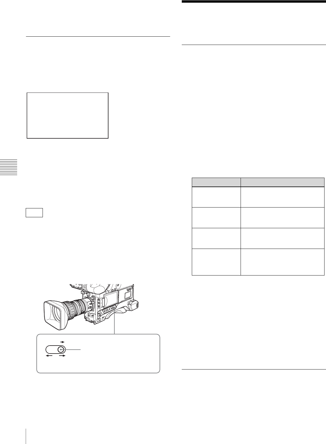
140 Adjustments and Settings from Menus
Chapter 5 Menu Displays and Detailed Settings
To cancel changing the shot ID
Before executing step 5 of “Setting the Shot ID” on page
139, move b to ESC, and press the MENU knob.
Showing the Status Display
You can confirm the settings or status of the camcorder on
the screen by showing the status display.
Items shown in the status display
The status display allows you to confirm the following
items related to the camera setting.
• FORMAT: Video recording format set on this unit
• WHITE: White balance color temperature
• ASSIGN: The setting of ASSIGN switch (1 to 4)
• TIME CODE: DF or NDF
• COMPONENT OUT: Output from the VIDEO OUT
connector
• AUDIO: Audio recording format set on this unit
• F.MIC: Front microphone setting
• CH1 to CH4: Knob adjustment for each audio channel
To show the status display
Flick the MENU switch to STATUS when the menu is not
displayed.
Adjustments and
Settings from Menus
Setting Gain Values for the GAIN
Switch Positions
You can set the gain values for the L, M, and H positions
of the GAIN switch, which switches the gain of the video
amplifier.
(How to select an item in the menu screen: Turn the
MENU knob to move the b mark to the desired item.)
1
Display the GAIN SW page of the OPERATION
menu, and press the MENU knob.
For details on menu operations, see “Basic Menu
Operations” on page 131.
You can set the following items on the GAIN SW
page.
2
Select the item corresponding to the switch position,
and press the MENU knob.
3
Turn the MENU knob to select the gain value, and
press the MENU knob.
You can select from –3, 0, 3, 6, 9, 12, 18, 24, 30, 36,
42, and 48 dB.
To change the gain corresponding to another switch
position, repeat steps 2 and 3.
Selecting the Output Signals
(How to select an item in the menu screen: Turn the
MENU knob to move the b mark to the desired item.)
F330
FO RMAT : H D 5 0I SP
WH ITE : 3 200K
AS SIGN <1 >E ZMOD < 2> IR RCN
<3 > OFF < 4> OFF
TI ME CO DE : DF
CO MPONE NT O UT:HD Y Pb Pr
AU DIO : 16bi t 4c h
F, MIC : STER EO
CH 1: FR ON T CH2 : R EAR
CH 3: FR ON T CH4 : FR ONT
MENU
ON OFF
STATUS
The status display appears when
the MENU switch is flicked to
STATUS, and disappears when
the switch is released.
Item Description
GAIN LOW Sets the gain value corresponding
to the L position of the GAIN
switch.
GAIN MID Sets the gain value corresponding
to the M position of the GAIN
switch.
GAIN HIGH Sets the gain value corresponding
to the H position of the GAIN
switch.
GAIN TURBO When assigning TURBO to the
ASSIGN switch, sets the gain
value corresponding to the
ASSIGN switch !"##$%&'#$DR(*.

141
Adjustments and Settings from Menus
Chapter 5 Menu Displays and Detailed Settings
1
Display the OUTPUT page of the OPERATION
menu, and press the MENU knob.
For details on menu operations, see “Basic Menu
Operations” on page 131.
2
Select COMPONENT OUT, and press the MENU
knob.
3
Select one of the following, and press the MENU
knob.
AUTO: Switch between HD YPbPr and SD YPbPr,
according to the recording format. This applies to
both recording and playback.
HD YPbPr: Regardless of the recording format,
output HD YPbPr when recording. Output SD
YPbPr only when playing back DVCAM format.
SD YPbPr: Regardless of the recording format,
output SD YPbPr. This applies to both recording
and playback.
1
Display the OUTPUT page of the OPERATION
menu, and press the MENU knob.
For details on menu operations, see “Basic Menu
Operations” on page 131.
2
Select VIDEO OUT SEL, and press the MENU knob
again.
3
Turn the MENU knob to select the desired setting, and
press the MENU knob.
HD Y: Outputs the HD Y signal.
VBS: Outputs the analog composite video signal.
When VBS is selected, connect to the VIDEO IN
connector of the video monitor. This setting
allows you to save the power.
Setting the Color Temperature
Manually
You can manually adjust the value of the white balance by
setting the color temperature.
(How to select an item in the menu screen: Turn the
MENU knob to move the b mark to the desired item.)
1
Display the WHITE page of the PAINT menu, and
press the MENU knob.
For details on menu operations, see “Basic Menu
Operations” on page 131.
2
Select the desired setting item, and press the MENU
knob.
You can set the following items on the WHITE page.
The above table shows the adjustment of the white
balance of channel A. Items followed by <B> are used
to adjust the white balance of channel B.
3
Turn the MENU knob to select the desired setting, and
press the MENU knob.
4
Repeat steps 2 and 3 until you have set all of the
desired items.
Specifying an Offset for the Auto
White Balance Setting
By setting an offset for the value of auto white balance,
you can make the picture warmer or colder.
(How to select an item in the menu screen: Turn the
MENU knob to move the b mark to the desired item.)
1
Display the OFFSET WHITE page of the
OPERATION menu, and press the MENU knob.
For details on menu operations, see “Basic Menu
Operations” on page 131.
2
Select the desired setting item, and press the MENU
knob.
You can set the following items in the OFFSET
WHITE page.
F330
F350
Item Description
COLOR TEMP
<A> Sets the color temperature for the
desired value. Adjust the value
while looking at the real image
because error tends to be bigger
for adjustment of high color
temperature.
C TEMP BAL <A> Adjusts the value more precisely
when the color temperature
adjustment through COLOR
TEMP is not satisfactory.
R GAIN <A> Changes only the value of R
GAIN.
B GAIN <A> Changes only the value of B
GAIN.
D5600K<A> Sets the color temperature to
approximately 5600K
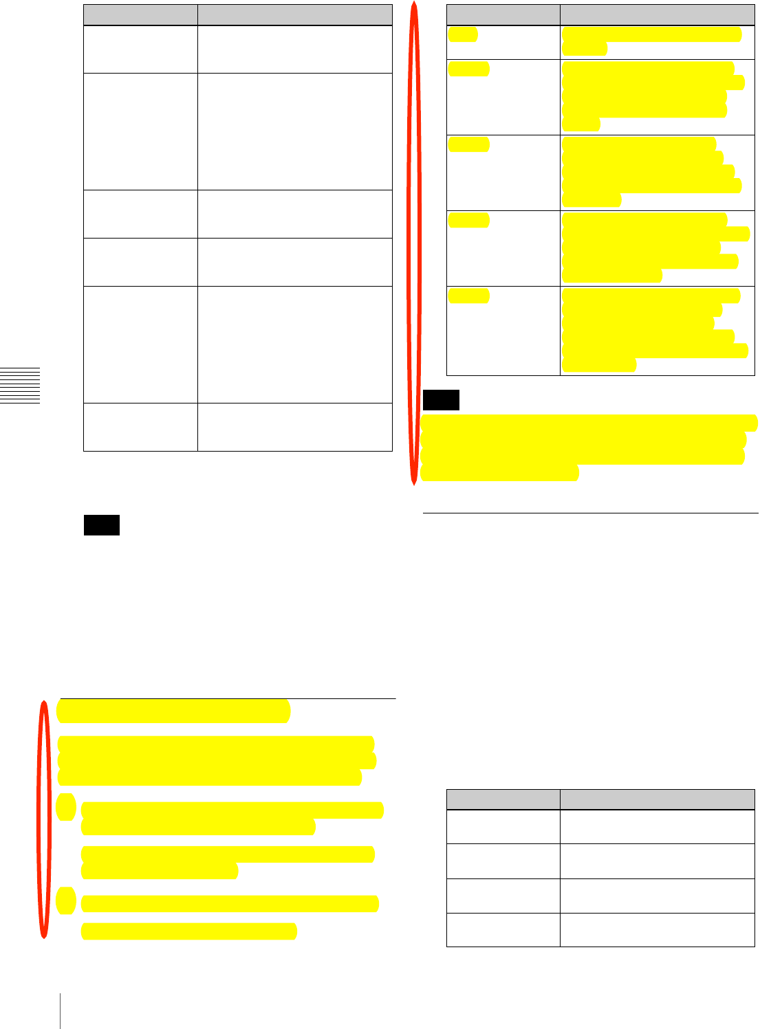
142 Adjustments and Settings from Menus
Chapter 5 Menu Displays and Detailed Settings
3
Set the WHITE BAL switch to the channel (A or B)
that you want to set.
If the WHITE BAL switch is not set to A or B, the
adjusted value is not reflected in the video output even
though you carry out the following operation.
4
Turn the MENU knob to perform the settings for each
item, and press the MENU knob.
If you want to set the other channel, go back to step 2.
Selecting Gamma Tables
You can select gamma curves from among five preset
patterns, for times when you want to achieve film-like
gradations and color reproduction and other effects.
1
Display the GAMMA SELECT page of the PAINT
menu, and then press the MENU knob.
For details on menu operations, see “Basic Menu
Operations” on page 131.
2
Select the desired item and press the MENU knob.
The following settings are available.
When you select CINE1 to CINE4, the knee point is fixed
at a preset value and cannot be adjusted, even if you set
KNEE in the SWSTATUS page of the PAINT menu to
ON. DCC is also disabled.
Assigning Functions to ASSIGN
Switches
You can assign the desired function to any of the ASSIGN
switches.
(How to select an item in the menu screen: Turn the
MENU knob to move the b mark to the desired item.)
1
Display the ASSIGNABLE page on the OPERATION
menu, and press the MENU knob.
For details on menu operations, see “Basic Menu
Operations” on page 131.
You can assign functions by using the following items.
Item Description
OFFSET WHITE
<A> Selects whether the offset
adjusted on this page is added to
the white balance for channel A.
WARM-COOL <A> When OFFSET WHITE <A> is
ON, sets the offset for the white
balance of channel A, using the
color temperature. Adjust the
value while looking at the real
image because error tends to be
bigger for adjustment of high color
temperature.
COLOR FINE <A> Adjusts the value more precisely if
the adjustment by WARM-COOL
<A> is not satisfactory.
OFFSET WHITE
<B> Selects whether the offset
adjusted on this page is added to
the white balance for channel B.
WARM-COOL <B> When OFFSET WHITE <B> is
ON, sets the offset for the white
balance of channel B, using the
color temperature. Adjust the
value while looking at the real
image because error tends to be
bigger for adjustment of high color
temperature.
COLOR FINE <B> Adjusts the value more precisely if
the adjustment by WARM-COOL
<B> is not satisfactory.
Note
Item Description
STD Standard setting (factory default
setting)
CINE1 This smoothes the contrasts in
darker sections and accentuates
gradation changes in brighter
sections, for a calm and quiet
effect.
CINE2 This gives almost the same
results as CINE1. Select this
when you want to obtain 100%
video signals for editing or other
purposes.
CINE3 This emphasizes the contrast
between light and dark more than
CINE1 and CINE2, and also
accentuates gradation changes
on the black side.
CINE4 This emphasizes the contrast in
dark section even more than
CINE3. Contrasts in darker
sections are weaker than STD,
and contrasts in brighter sections
are stronger.
Note
Item Description
ASSIGN SW <1> Assigns the function to ASSIGN 1
switch.
ASSIGN SW <2> Assigns the function to ASSIGN 2
switch.
ASSIGN SW <3> Assigns the function to ASSIGN 3
switch.
ASSIGN SW <4> Assigns the function to ASSIGN 4
switch.
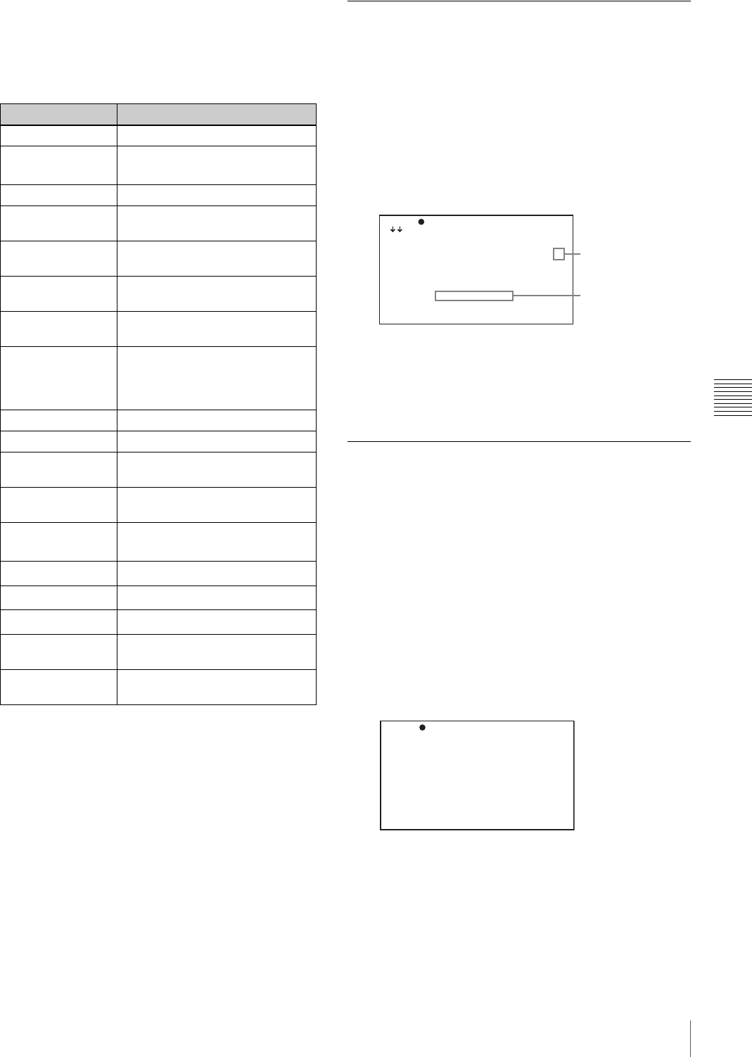
143
Adjustments and Settings from Menus
Chapter 5 Menu Displays and Detailed Settings
2
Select the desired switch (ASSIGN SW <1> to <4>),
and press the MENU knob.
The corresponding ASSIGN SW (1 to 4) SEL window
appears. You can assign one of the following functions
to the ASSIGN switch.
a) Even when the MARKER item is set to OFF on the MARKER 1 page
of the OPERATION menu, the ASSIGN switches allow you to turn
the display of all markers on or off.
b) Function assignable ASSIGN SW 1 and ASSIGN SW 2 switches
only
c) Abbreviation for Total Level Control System. A function to operate
the automatic gain control (AGC) and electronic shutter (AE) to
adapt to varying lighting conditions while shooting.
d) Use when shooting a subject at which a spotlight is directed.
e) Use when shooting a backlit subject.
3
Select the desired function, and press the MENU knob.
The function is assigned, and the ASSIGNABLE page
appears again.
Selecting the Lens File
You can change the lens file according to the lens in use.
1
Display the LENS FILE menu of the FILE menu, and
press the MENU knob.
For details on menu operations, see “Basic Menu
Operations” on page 131.
The LENS FILE page shows the name and the iris
setting value of the lens currently selected.
2
Select LENS AUTO RECALL, and press the MENU
knob.
3
Select ON, and press the MENU knob.
Selecting the Aspect Ratio
Switching the aspect ratio for DVCAM
recording
You can switch the aspect ratio for DVCAM recording.
(How to select an item in the menu screen: Turn the
MENU knob to move the b mark to the desired item.)
1
Display the FORMAT menu of the USER
(OPERATION) menu, and press the MENU knob.
For details on menu operations, see “Basic Menu
Operations” on page 131.
2
Select ASPECT RATIO (DV), and press the MENU
knob.
3
Turn the MENU knob to select the desired aspect ratio
(16:9/4:3), and press the MENU knob.
Function Description
OFF Assigns no function.
MARKER Assigns the function to turn the
display of all markers on or off. a)
RETAKE Delete the last recorded clip.
ATW Assigns the function to turn ATW
on or off.
LENS RET Assigns the recording review
function.
REC SWITCH Assigns the recording start/stop
function.
TURBO SWITCH Assigns the turbo gain value set
for GAIN TURBO !"##$%&'#$DRE*.
FREEZE MIX Assigns the function to output the
freeze image and camera input
alternately, to allow frame
alignment (automatic switching).
SHOT MARK1 Assigns the shot mark 1 function.
SHOT MARK2 Assigns the shot mark 2 function.
EZ MODE b) Assigns EZ mode ON/OFF
switching.
EZ FOCUS b) Assigns EZ focus ON/OFF
switching.
SKIN DETAIL ON/
OFF b)
Assigns SKIN DETAIL ON/OFF
switching.
SPOT LIGHT b) Auto iris spotlight mode d)
BACK LIGHT b) Auto iris backlight mode e)
TLCS b), c) TLCS ON/OFF
IR REMOTE b) Infrared remote commander ON/
OFF
PICTURE CACHE Assigns Picture Cache function
ON/OFF switching.
TO P F 04 LE NS F ILE 1
L ENS F IL E RECAL L: EX EC
L ENS F IL E STORE : EX EC
F .ID [C ]V CL-71 9B XS
S OURCE : ----- -- -
L ENS N O OF FSET : EX EC
I RIS G AI N :
L ENS A UT O RECAL L: ON
< LENS IN FO RMATI ON >
L .ID: VC L- 719BX S
L .MF: Ca nn on
Lens file number
Lens name and iris
setting value
TO P 0 01 FO RM AT
S YSTEM : 6 0I
R EC FO RM AT : D VC AM
B IT RA TE ( HD) : SP
A UDIO CH ( HD) : 4 ch
A SPECT R AT IO(DV ): 16 :9
C OUNTR Y : NTS C( J) AR EA

144 Adjustments and Settings from Menus
Chapter 5 Menu Displays and Detailed Settings
Setting the aspect ratio for SD playback in
HD mode
When outputting SD video down-converted from HD
video, you can switch the aspect ratio.
(How to select an item in the menu screen: Turn the
MENU knob to move the b mark to the desired item.)
1
Display the OUTPUT page of the OPERATION
menu, and press the MENU knob.
2
Select HDtSD(PLAY BACK), and press the MENU
knob.
3
Turn the MENU knob to select the desired aspect ratio
(16:9/4:3), and press the MENU knob.
The HD analog composite output from the PDW-F330 and
the HDSDI output from the PDW-F350 are always of the
aspect ratio of 16:9.
To display the aspect ratio of 16:9 on the
viewfinder screen
When the recording format is DVCAM and the aspect ratio
is 16:9, you can display the indication “16:9” on the
viewfinder screen by setting DISP 16:9 on the VF DISP 1
page of the OPERATION menu to ON.
For details, see “Selecting the Display Items” on page
136.
About the CCD Scan Mode
This unit allows you to record in progressive scan mode as
well as in interlace scan mode. You can select the scan
mode from the following modes using the FORMAT page
of the OPERATION menu.
• 60i (interlace scan) mode
• 30P (progressive scan) mode
• 23.98P mode
Pulldown method for DVCAM format recording in 23.98P mode
DVCAM video signals recorded in 23.98P mode are 2-3
pulled down, and recorded on a disc as 60i signals.
.
Note
DF/NDF Purpose Notes
DF Obtain an effect similar
to that obtained by
23.98P shooting while
maintaining interlace
scan mode.
–
NDF Re-convert to 23.98P
with nonlinear editing
software (NLE).
(Select according to
your NLE.)
• You can start recording at frame 0 or frame 5 of the timecode. Therefore, when setting
the timecode or recording in backspace editing mode, the value of the least significant
digit is limited to 0 or 5.
• There will be noise on the recorded image if you change the operating mode for the
internal timecode generator using the F-RUN/SET/R-RUN switch on the side control
panel while recording.
• The video and audio signal and timecode output via i.LINK may not be consecutive
when recording starts.
Notes on 2-3 pulldown
• When the PRESET/REGEN/CLOCK switch on the side control panel is set to CLOCK,
this unit operates in DF mode. The synchronization of the timecode and the pulled-
down picture is disabled.
• When drop-frame timecode is input via the TC IN connector, this unit operates in DF
mode and synchronization of the pulled-down picture and the timecode is disabled.
This setting will continue in effect until the timecode setting (F-RUN/R-RUN or DF/NDF)
is changed.

145
Adjustments and Settings from Menus
Chapter 5 Menu Displays and Detailed Settings
2-3 pulldown in 23.98P mode
A O
A ( O + E ) B ( O + E ) C ( O + E ) D ( O + E ) A ( O + E )
A E B O B E B O C E C O D E D O D E A O A E
O: Odd E: Even
After reading from the CCDs in 23.98 frames per second, a pulldown
conversion is carried out to the 30 frames (29.97 frames per second)
of the normal progressive scan mode.
1/29.97 seconds
1/23.98 seconds
CCD output
Video output signal
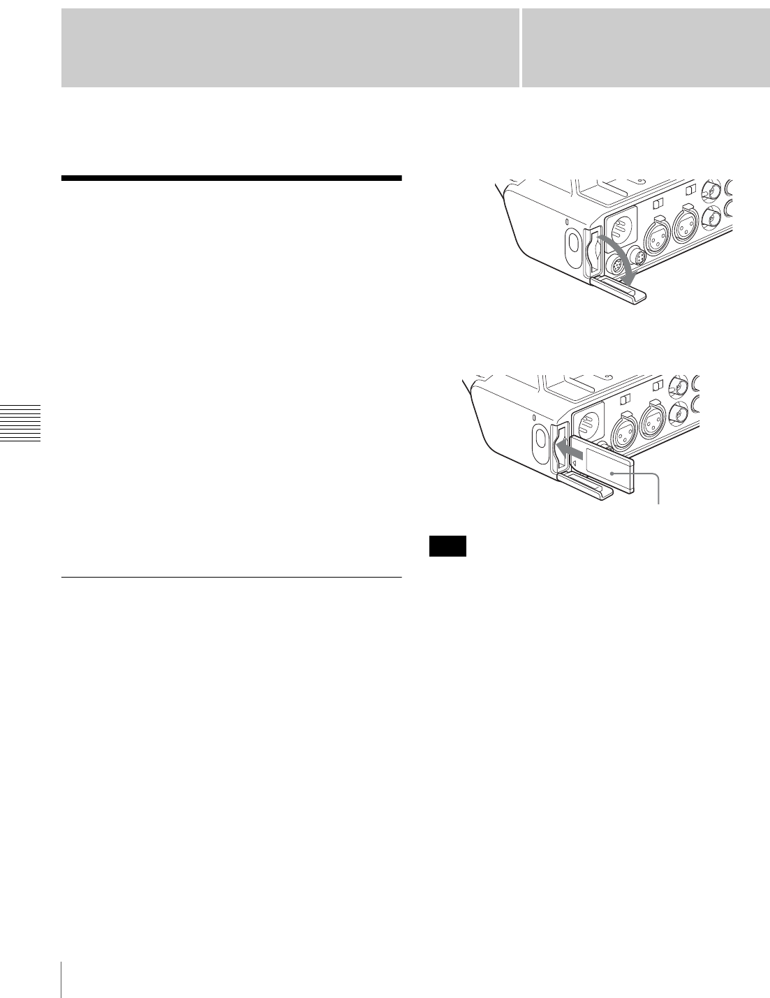
Chapter6
146 Saving and Loading User Files
Chapter 6 Saving and Loading the User Setting Data
Saving and Loading the
User Setting Data
Saving and Loading User
Files
The camcorder is equipped with a “Memory Stick” slot,
which enables you to save the settings in the USER menu
as a user file onto the “Memory Stick”. You can load these
files from the “Memory Stick” for immediate recall of a
particular setting configuration. In addition to user files,
you can save scene files, lens files and ALL files in a
“Memory Stick”.
When a menu is displayed, you can set up the camcorder
so that inserting a “Memory Stick” automatically jumps to
the appropriate file-related menu page.
For details about scene files, see “Saving and Loading
Scene Files” on page 150.
For details about lens files and ALL files, refer to “Menu
List” on page 111.
Handling the “Memory Stick”
The “Memory Stick” can be inserted to or removed from
the camcorder with the power turned on or off.
“Memory Stick” usable with this
camcorder
With this camcorder, you can use a “Memory Stick” whose
capacity does not exceed 128 MB.
For details, see “About a “Memory Stick”” on page 174.
To insert a “Memory Stick”
1
Open the “Memory Stick” slot cover on the back of the
camcorder.
2
Insert the “Memory Stick” with its label side facing the
“Memory Stick” logo on the camcorder.
If it does not fit into the slot properly or if there is some
resistance when you insert it, the “Memory Stick” may be
turned around or upside down. Do not force the “Memory
Stick” into the slot. Confirm the direction of the notch and
arrow on the “Memory Stick” before inserting the
“Memory Stick”, and then try inserting it again.
To remove the “Memory Stick”
1
Check that the access indicator is not lit, then gently
press in the “Memory Stick” once and release.
The “Memory Stick” pops out.
Note
Label side of “Memory Stick”
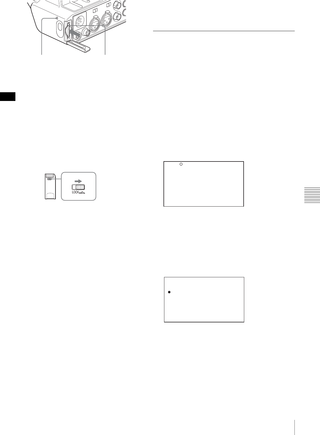
147
Saving and Loading User Files
Chapter 6 Saving and Loading the User Setting Data
2
Pull the “Memory Stick” towards you to withdraw it
from the slot.
Do not remove the “Memory Stick” while the access
indicator is lit. You may lose data, or damage the “Memory
Stick”.
To protect saved data
To prevent accidental erasure of important setup data, slide
the LOCK switch on the “Memory Stick” right to the write
protect position.
It is now impossible to write or delete data on the
“Memory Stick”. If you try to do so, the message
“MEMORY STICK LOCKED” appears and the data
cannot be overwritten or deleted.
Notes on using and storing the “Memory
Stick”
To use and store the “Memory Stick”, note the following
points.
• Avoid touching the connector of the “Memory Stick” or
contacting it with a metal object.
• When attaching a label to the “Memory Stick”, use only
the label supplied for the “Memory Stick”.
• Do not drop, bend, or submit the “Memory Stick” to
external shock.
• Do not disassemble or modify the “Memory Stick”.
• Avoid getting liquids on the “Memory Stick”.
• Avoid using or storing the “Memory Stick” in a location
subject to:
- extremely high temperature such as the hot inside of a
car or the outdoors exposed to a burning sun, or a place
near a heater.
- direct sunlight.
• When storing and carrying the “Memory Stick”, keep it
in its original case to ensure protection of important data.
• Do not format the “Memory Stick” using a PC.
Format the “Memory Stick” on the MEMORY STICK
page of the FILE menu.
Saving USER Menu Data (User File)
to the “Memory Stick”
USER menu settings stored in the camcorder as user files
can be saved to the “Memory Stick”.
You can save up to 100 user files to the “Memory Stick”.
Insert the “Memory Stick” into the “Memory Stick” slot,
then proceed as follows.
(How to select an item in the menu screen: Turn the
MENU knob to move the b mark to the desired item.)
1
Display the USER FILE page of the FILE menu, and
press the MENU knob.
For details on menu operations, see “Basic Menu
Operations” on page 131.
To set a file ID for the data to be saved
Set the file ID before going to step 2.
For details on setting the file ID, see “To set the file
ID” on page 148.
2
Select USER FILE SAVE, and press the MENU knob.
The USER SAVE page appears.
Up to 20 pages, from P00 to P19, can be used to save
user files to the “Memory Stick”. Each page can hold
up to five files.
3
Turn the MENU knob until the page which contains
the desired file number appears, and press the MENU
knob.
Note
Gently press in and release.
Check that the access
indicator is not lit.
U SER F IL E LOAD : EX EC
U SER F IL E SAVE : EX EC
F .ID :
ss sssssssss sssss
U SER P RE SE T : EX EC
TO P F 01 US ER F ILE
D ISPLA Y MO DE : A LL
001.NEW FILE
002.NEW FILE
003.NEW FILE
004.NEW FILE
005.NEW FILE
ESC?P00 USER SAVE
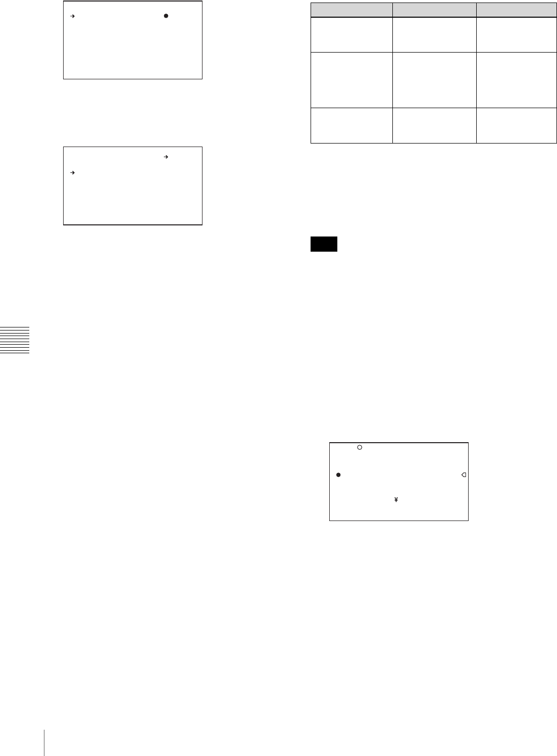
148 Saving and Loading User Files
Chapter 6 Saving and Loading the User Setting Data
4
Select the desired file number, and press the MENU
knob.
The message “SAVE OK? YES b NO” appears.
5
To carry out the save, select YES and press the MENU
knob.
To cancel, press the MENU knob leaving b pointing to
NO.
The access indicator lights. When the saving is
completed, the message “COMPLETE” appears and
the access indicator goes off.
If no “Memory Stick” has been inserted, the message
“NO MEMORY STICK” will appear. Insert a
“Memory Stick”, and carry out the operation once
again.
If you select a file number where data has already
been saved
The message “OVERWRITE OK? YES b NO”
appears.
• To stop overwriting, press the MENU knob leaving
b pointing to NO.
• To overwrite, select YES and press the MENU knob.
You can select the information displayed on each
USER SAVE or USER LOAD page.
For details, see “To select the file information items to
be displayed” on page 149.
About the USER menu settings to be saved in the
“Memory Stick”
Settings for items on all pages of the USER menu are
saved in the “Memory Stick” as a user file.
If data cannot be saved
If one of the following error messages appears during or
after the save operation, then the data was not saved.
To set the file ID
Before data is saved to a “Memory Stick”, it is useful to set
a file ID for the “Memory Stick” to identify it.
When data is saved to a “Memory Stick”, the file ID is
saved to the “Memory Stick” together with the data.
Set the file ID before saving data in the “Memory Stick”.
Otherwise, the file ID is not saved with the other data.
(How to select an item in the menu screen: Turn the
MENU knob to move the b mark to the desired item.)
1
Display the USER FILE page of the FILE menu, and
press the MENU knob.
For details on menu operations, see “Basic Menu
Operations” on page 131.
2
Select F. ID, and press the MENU knob.
A character table appears.
3
Follow steps 3 and 4 described in “Setting the Shot
ID” on page 139 to enter characters.
4
When you have finished entering the file ID, turn the
MENU knob to move x to END, and press the MENU
knob.
The entered file ID is now displayed.
D ISPLA Y MO DE : A LL
0 01.NE W FI LE
0 02.NE W FI LE
0 03.NE W FI LE
0 04.NE W FI LE
0 05.NE W FI LE
ES C P 00 US ER S AVE
D ISPLA Y MO DE : A LL
0 01.NE W FI LE
0 02.NE W FI LE
0 03.NE W FI LE
0 04.NE W FI LE
0 05.NE W FI LE
ES CP0 0 USE R SA VE
SAVE O K? Y ES N O
If a file number is
followed by “NEW
FILE”, this means
that the file is empty.
If data is stored in the
file, the file number is
followed by the file
name.
Error message Cause Action
NO MEMORY
STICK (flashing) No “Memory Stick”
is inserted. Insert or reinsert
the “Memory
Stick”.
MEMORY STICK
LOCKED The LOCK switch
on the “Memory
Stick” is set to the
write protect
position.
Set the LOCK
switch to the write
enable position.
MEMORY STICK
ERROR (flashing) Circuit or “Memory
Stick” fault. Recheck and
consult your Sony
dealer.
Note
U SER F IL E LOAD : E XEC
U SER F IL E SAVE : E XEC
F .ID : ?
x
i #$%&' () *+ ,-./0 12 34 56 78
9: ;<=>? @A BC DEFGH IJ KL MN OP
QR STUVW XY Z[ ]abc de fg hi jk
lm nopqr st uv wxyz~
IN S DEL R ET ES C END
TO P F 01 US ER F ILE
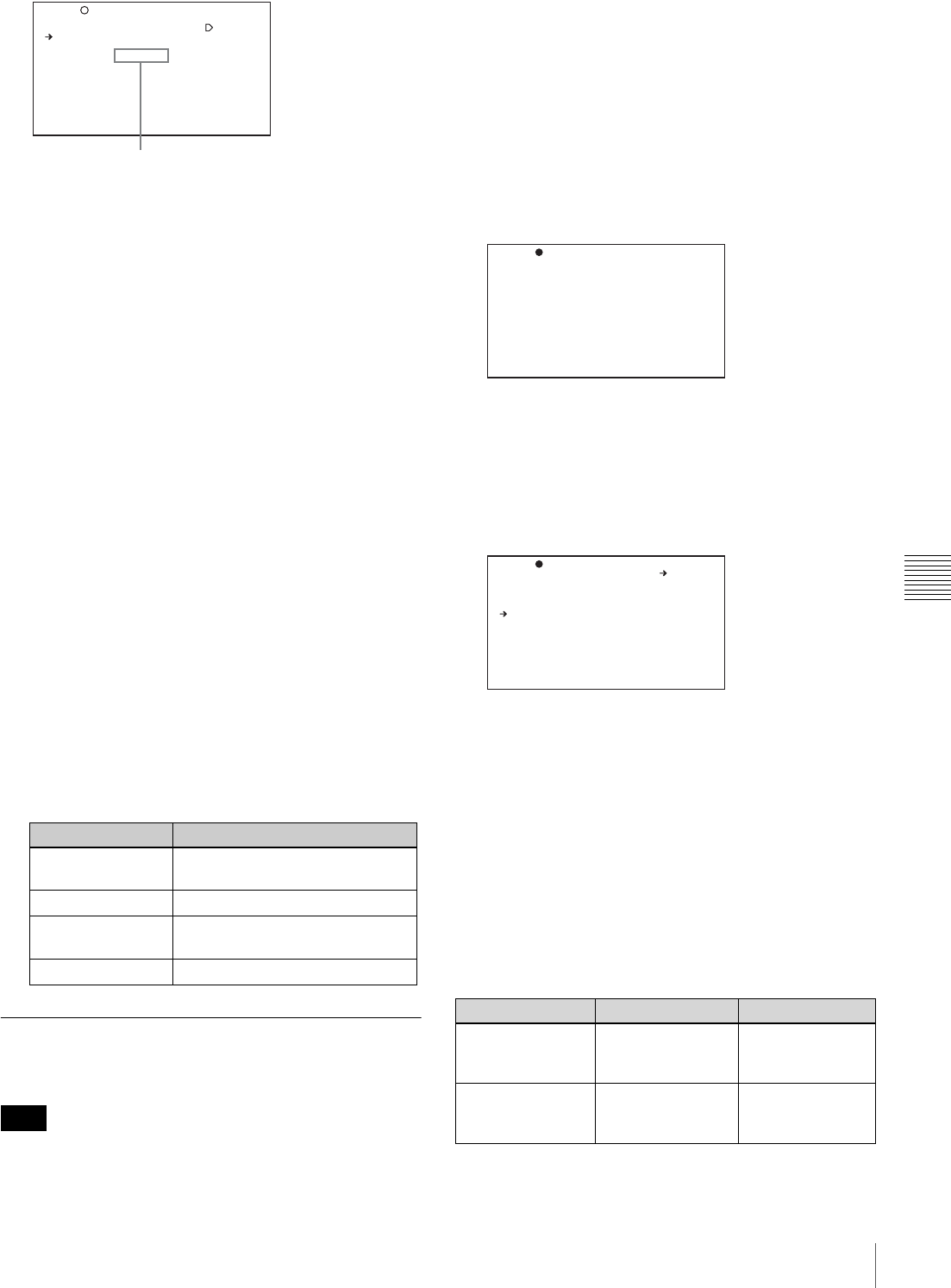
149
Saving and Loading User Files
Chapter 6 Saving and Loading the User Setting Data
After setting the file ID, carry out the procedure from
step 2 in “Saving USER Menu Data (User File) to the
“Memory Stick”” on page 147.
The set file ID is saved in the “Memory Stick” with the
data.
To select the file information items to be
displayed
You can select the file information items to be displayed
on the USER FILE SAVE page and USER FILE LOAD
page (P00 to P19), that are the pages used to save and call
up the data to and from “Memory Stick”.
(How to select an item in the menu screen: Turn the
MENU knob to move the b mark to the desired item.)
1
Display a USER FILE LOAD page or USER FILE
SAVE page of the USER FILE menu, and press the
MENU knob.
For details on menu operations, see “Basic Menu
Operations” on page 131.
2
Press the MENU knob, then select the DISPLAY
MODE, and press the MENU knob.
3
Select the desired type of file information (see the
following table), and press the MENU knob.
Loading Saved Data From a
“Memory Stick”
The data loaded from the “Memory Stick” overwrites the
data saved in the camcorder.
(How to select an item in the menu screen: Turn the
MENU knob to move the b mark to the desired item.)
1
Display the USER FILE page of the FILE menu, and
press the MENU knob.
For details on menu operations, see “Basic Menu
Operations” on page 131.
2
Select USER FILE LOAD, and press the MENU knob.
The P00 USER LOAD page appears.
3
Turn the MENU knob until the page which contains
the desired file appears, then press the MENU knob.
4
Press the MENU knob. Then select the desired file
number, and press the MENU knob.
The message “LOAD OK? YES b NO” appears.
5
To carry out the load, select YES and press the MENU
knob.
To cancel, press the MENU knob leaving b pointing to
NO.
The access indicator lights.
When the load is completed, the message
“COMPLETE” appears and the access indicator goes
off.
The USER FILE page appears again.
If data cannot be loaded
If one of the following error messages appears during or
after the load operation, then the data was not loaded.
Display type Description
ALL File ID (10 characters) and date
(year/month/day)
F.ID File ID (16 characters)
DATE Date saved (year/month/day/
hours/minutes/seconds)
MODEL Information on the model
Note
U SER F IL E LOAD : EX EC
U SER F IL E SAVE : EX EC
F .ID : I D- 001
U SER P RE SE T : EX EC
TO P F 01 US ER F ILE
File ID that has been set appears.
Error message Cause Action
NO MEMORY
STICK (flashing) No “Memory Stick”
is inserted. Insert or reinsert
the “Memory
Stick”.
MEMORY STICK
ERROR (flashing) Circuit or “Memory
Stick” fault. Recheck, and
consult your Sony
dealer.
D ISPLA Y MO DE : A LL
0 01.US ER 1 J AN /0 5/ 06
0 02.US ER 2 J AN /1 5/ 06
0 03.NO F IL E
0 04.US ER 4 F EB /0 5/ 06
0 05.US ER 5 F EB /2 0/ 06
TO P?P 00 US ER L OAD
D ISPLA Y MO DE : A LL
0 01.US ER 1 J AN /0 5/ 06
0 02.US ER 2 J AN /1 5/ 06
0 03.NO F IL E
0 04.US ER 4 F EB /0 5/ 06
0 05.US ER 5 F EB /2 0/ 06
TO P P 00 US ER L OAD
LOAD O K? Y ES N O

150 Saving and Loading Scene Files
Chapter 6 Saving and Loading the User Setting Data
Saving and Loading
Scene Files
You can save various settings for shooting a particular
scene as a scene file. Loading the scene file, you can
quickly recreate setup conditions suitable for the scene.
You can save up to five scene files in the camcorder
memory and up to 100 scene files in a “Memory Stick”.
You can also load data from the “Memory Stick” into the
camcorder memory.
Data that can be saved in a scene file
You can save the following data in a scene file:
• Values adjusted using the PAINT menu
• Shutter speed settings made in the standard mode and
ECS mode
For details of the PAINT menu, refer to “PAINT menu” on
page 118.
Saving a Scene File
To save a scene file to the “Memory Stick”, insert the
“Memory Stick” into the “Memory Stick” slot before
starting the operation.
(How to select an item in the menu screen: Turn the
MENU knob to move the b mark to the desired item.)
1
Display the SCENE FILE page of the FILE menu, and
press the MENU knob.
For details on menu operation, see “Basic Menu
Operations” on page 131.
To set a file ID for the data to be saved
Set the file ID before going to step 2.
For details on setting the file ID, see “To set the file
ID” on page 148.
2
Select SCENE STORE, and press the MENU knob.
The SCENE STORE page appears.
FILE ERROR
(flashing) The “Memory
Stick” contains
data that cannot be
loaded into this
camcorder.
Data saved to a
“Memory Stick”
using a camcorder
whose model is
not the same as
this camcorder
cannot be loaded
into this
camcorder.
Error message Cause Action
s
1 :STANDARD
s
2 :STANDARD
s
3 :STANDARD
s
4 :STANDARD
s
5 :STANDARD
s
ST ANDAR D
S CENE RE CA LL : EX EC
S CENE ST OR E : EX EC
F .ID: ST AN DARD
TO P F 04 SC EN E FILE
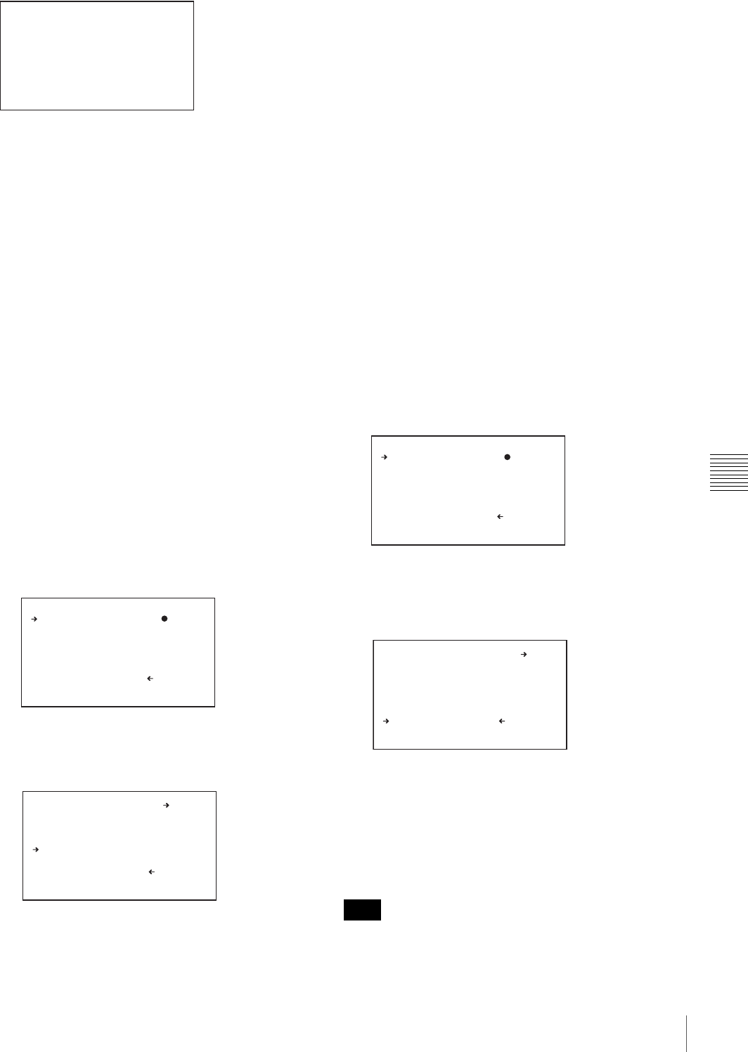
151
Saving and Loading Scene Files
Chapter 6 Saving and Loading the User Setting Data
3
Press the MENU knob, then select the desired file
number, and press the MENU knob again.
The file to be saved is selected.
When no “Memory Stick” is inserted
Select the desired memory number, and press the
MENU knob.
When the save is completed, the SCENE FILE page
appears again.
When you select a file number where data has
already been saved
The message “OVERWRITE OK? YES b NO”
appears.
• To cancel the overwriting, press the MENU knob
leaving b positioning to NO.
• To overwrite, select YES and press the MENU knob.
When a “Memory Stick” is inserted
You can use up to 20 pages, from P01 to P20, to save
scene files in the “Memory Stick”. Each page can hold
up to five files.
1Turn the MENU knob until the page which
contains the desired file appears, then press the
MENU knob.
2Select the desired file number, and press the
MENU knob.
The message “STORE OK? YES b NO” appears.
3To carry out the storing, select YES and press the
MENU knob.
To cancel, press the MENU knob leaving b
pointing to NO.
You can select the file information items to be
displayed on each page of SCENE STORE and
SCENE RECALL.
For details, see “To select the file information items to
be displayed” on page 149.
To save scene files stored in the
camcorder memory to the “Memory Stick”
The five scene files stored in the camcorder memory can
be saved to the “Memory Stick” all in a single operation.
(How to select an item in the menu screen: Turn the
MENU knob to move the b mark to the desired item.)
1
Display the SCENE FILE page of the FILE menu, and
press the MENU knob.
For details on menu operations, see “Basic Menu
Operations” on page 131.
2
Select SCENE STORE, and press the MENU knob.
3
Select the desired SCENE STORE page, and press the
MENU knob.
4
Select 5FILE SAVE b MEM1-5, and press the MENU
knob.
The message “STORE OK? YES b NO” appears.
5
To carry out the save, select YES and press the MENU
knob.
To cancel, press the MENU knob leaving b pointing to
NO.
When the save is completed, the message
“COMPLETE” appears.
If files have been saved in the page selected in step 3, those
files are replaced with files loaded from the camcorder
D ISPLA Y MO DE : A LL
M EM-01 :S TA NDARD
M EM-02 :S TA NDARD
M EM-03 :S TA NDARD
M EM-04 :S TA NDARD
M EM-05 :S TA NDARD
ES C?P 00 SC EN E STORE
DISPLAY MODE : ALL
001.SCENE1 FEB/05/02
0 02.ST AN DA RD
0 03.ST AN DA RD
0 04.ST AN DA RD
0 05.ST AN DA RD
***.5FILE SAVE MEM1-5
ES C P 01 SC EN E STORE
D ISPLA Y MO DE : A LL
0 01.SC EN E1 F EB /0 5/ 02
0 02.ST AN DA RD
0 03.ST AN DA RD
0 04.ST AN DA RD
0 05.ST AN DA RD
* **.5F IL E SAVE ME M1 -5
ES C P 01 SC EN E STORE
STOR E OK ? Y ES N O
Note
D ISPLA Y MO DE : A LL
0 01.SC EN E1 F EB /0 5/ 02
0 02.SC EN E2 F EB /0 6/ 02
0 03.NO F IL E
0 04.SC EN E4 F EB /0 8/ 02
0 05.SC EN E5 F EB /0 8/ 02
* **.5F IL E SAVE ME M1 -5
ES C P 01 SC EN E STORE
DISPLAY MODE : ALL
001.SCENE1
002.SCENE2
0 03.NO F IL E
004.SCENE4
005.SCENE5
***.5FILE SAVE MEM1-5
ESC P01 SCENE STORE
STORE OK? YES NO
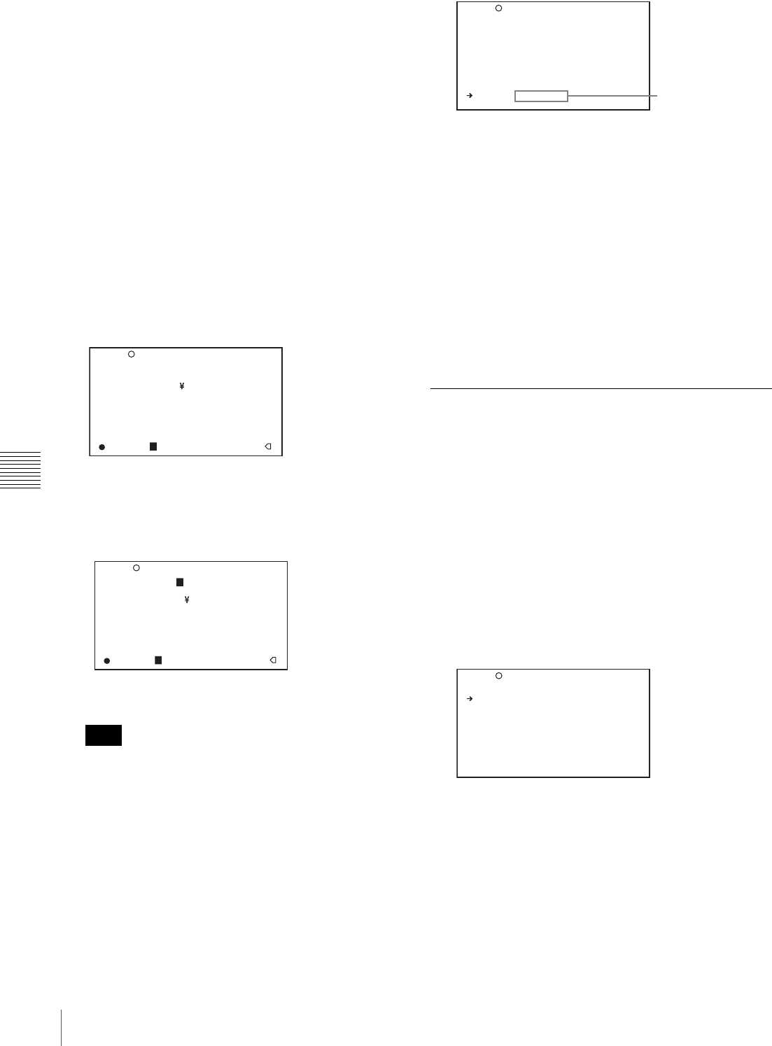
152 Saving and Loading Scene Files
Chapter 6 Saving and Loading the User Setting Data
memory. For example, files from 001 to 005 are replaced
by the above procedure.
To set the file ID
Before the data is saved as a scene file, it is useful to set a
file ID to identify it. The set file ID is saved together with
the data.
(How to select an item in the menu screen: Turn the
MENU knob to move the b mark to the desired item.)
1
Display the SCENE FILE page of the FILE menu, and
press the MENU knob.
For details on menu operations, see “Basic Menu
Operations” on page 131.
2
Select F. ID, and press the MENU knob.
A character table appears.
3
Press the MENU knob. Then turn the MENU knob
until x moves to the character position that you want
to select, and press the MENU knob.
4
Repeat step 3 for each of the remaining characters.
Set the file ID before saving the scene file. Otherwise,
the file ID is not saved with the other data.
5
When you have finished character inputting, turn the
MENU knob to move x over END, and press the
MENU knob.
The file ID is set, and the SCENE FILE page appears
again.
Carry out the procedure from step 2 in “Saving a
Scene File” on page 150. The set file ID is saved
together with the data.
To select the file information items to be
displayed
You can select the items of file information to be displayed
on the SCENE STORE pages (P01 to P20) or the SCENE
RECALL pages (P01 to P20) used for saving data to or
loading data from a “Memory Stick”.
For details to select the item, “To select the file
information items to be displayed” on page 149.
Loading Scene Files
(How to select an item in the menu screen: Turn the
MENU knob to move the b mark to the desired item.)
1
Display the SCENE FILE page of the FILE menu, and
press the MENU knob.
For details on menu operations, see “Basic Menu
Operations” on page 131.
2
To load the scene file stored in the camcorder, select
the desired file number, and press the MENU knob.
s on the left of the file number changes to x. The
camcorder is set up according to the loaded scene file.
To cancel the selected scene file
Turn the MENU knob to move b to x, and press the
MENU knob. x changes to s. The camcorder returns
to the settings before selecting this scene file.
To load a scene file saved in the “Memory Stick”
1Select SCENE RECALL, and press the MENU
knob.
The SCENE RECALL page appears.
Note
! #$%&' () *+ ,-./0 12 34 56 78
9: ;<=>? @A BC DEFGH IJ KL MN OP
QR STUVW XY Z[ ]abc de fg hi jk
lm nopqr st uv wxyz~
IN S DEL R ET E SC E ND
sSTAN DA RD
S CENE RE CA LL : EX EC
S CENE ST OR E : EX EC
F.ID :STA NDARD
TO P F 04 SC EN E FILE
Example: When entering the letter “+”
! #$%&' () *+, -./01 23 45 67 8
9: ;<=>? @A BC DEFGH IJ KL MN OP
QR STUVW XY Z[ ]abc de fg hi jk
lm nopqr st uv wxyz~
IN S DEL R ET E SC E ND
sSTAN DA RD
S CENE RE CA LL : EX EC
S CENE ST OR E : EX EC
F.ID :+TANDARD
TO P F 04 SC EN E FILE
s
1 :ST AN DA RD
s
2 :ST AN DA RD
s
3 :ST AN DA RD
s
4 :ST AN DA RD
s
5 :ST AN DA RD
s
ST ANDAR D
S CENE RE CA LL : EX EC
S CENE ST OR E : EX EC
F .ID: SC EN E21
TO P 04 SC EN E FILE
File ID
s
1 :SC EN E 25
x
2 :SC EN E 26
s
3 :SC EN E 27
s
4 :SC EN E 28
s
5 :NO F IL E
s
STANDARD
S CENE RE CA LL : EX EC
S CENE ST OR E : EX EC
F .ID : SC EN E21
TO P F 04 SC EN E FILE
153
Saving and Loading Scene Files
Chapter 6 Saving and Loading the User Setting Data
2Turn the MENU knob until the page which
contains the desired file appears.
3Press the MENU knob, then turn the MENU knob
to move b to the desired file number, and press the
MENU knob.
The message “RECALL OK? YES b NO”
appears.
3
To carry out the recall, select YES and press the
MENU knob.
To cancel, press the MENU knob leaving b pointing to
NO.
When the loading is completed, the message
“COMPLETE” appears. The camcorder is set up
according to the loaded scene file. If no file is present
with a particular file number, this is shown as “NO
FILE”.
To load scene files from the “Memory
Stick” into the camcorder memory
You can load up to five scene files stored in the “Memory
Stick” into the camcorder memory all in a single operation.
(How to select an item in the menu screen: Turn the
MENU knob to move the b mark to the desired item.)
1
Display the SCENE FILE page of the FILE menu, and
press the MENU knob.
For details on menu operations, see “Basic Menu
Operations” on page 131.
2
Select SCENE RECALL, and press the MENU knob.
The SCENE RECALL page appears.
3
Turn the MENU knob until the SCENE RECALL
page which contains the desired scene files appears.
4
Press the MENU knob. Then select 5FILE LOAD B
MEM 1-5, and press the MENU knob.
The message “RECALL OK? YES b NO” appears.
5
To carry out the recall, select YES and press the
MENU knob.
To cancel, press the MENU knob leaving b pointing to
NO.
When loading is complete, the message
“COMPLETE” appears and the access indicator goes
off.
• The scene files loaded from the “Memory Stick”
overwrite data saved in the camcorder memory.
• To load the scene file saved in the camcorder memory
when the “Memory Stick” is inserted, return to the P00
SCENE RECALL page and load the desired scene file in
the camcorder memory.
• When there is no file to be loaded (shown as “NO
FILE”), an existing file of the same number is
unaffected. In the example shown in step 4, MEM(3) is
not overwritten.
Resetting the Settings of the
Camcorder to the Standard Settings
You can reset the settings of the camcorder to the standard
settings.
(How to select an item in the menu screen: Turn the
MENU knob to move the b mark to the desired item.)
1
Display the SCENE FILE page of the FILE menu, and
press the MENU knob.
For details on menu operations, see “Basic Menu
Operations” on page 131.
2
Select STANDARD, and press the MENU knob.
DISPLAY MODE : F.ID
MEM-1:STANDARD
MEM-2:STANDARD
MEM-3:STANDARD
MEM-4:STANDARD
M EM-5: NO F ILE
ES C?P 00 SC EN E RECAL L
D ISPLA Y MO DE : A LL
0 01.SC EN E1
0 02.SC EN E2
0 03.NO F IL E
0 04.SC EN E4
0 05.SC EN E5
* **.5F IL E LOAD ME M1 -5
ES C P 01 SC EN E RECAL L
RECA LL O K? Y ES N O
Notes
D ISPLA Y MO DE : A LL
0 01.SC EN E1
0 02.SC EN E2
0 03.NO F IL E
0 04.SC EN E4
0 05.SC EN E5
* **.5F IL E LOAD ME M1 -5
ES C P 01 SC EN E RECAL L
RECA LL O K? Y ES N O

154 Saving and Loading Scene Files
Chapter 6 Saving and Loading the User Setting Data
s displayed on the left of STANDARD changes to x.
When x changes to s once again, the settings of the
camcorder are reset to the settings.
If you press the MENU knob again while x is
displayed, the operation is cancelled and the
camcorder returns to the settings before STANDARD
was selected.
s
1 :SC EN E 25
s
2 :SC EN E 26
s
3 :SC EN E 27
s
4 :SC EN E 28
s
5 :NO F IL E
x
ST ANDAR D
S CENE RE CA LL : EX EC
S CENE ST OR E : EX EC
F .ID : SC EN E2
TO P F 04 SC EN E FILE
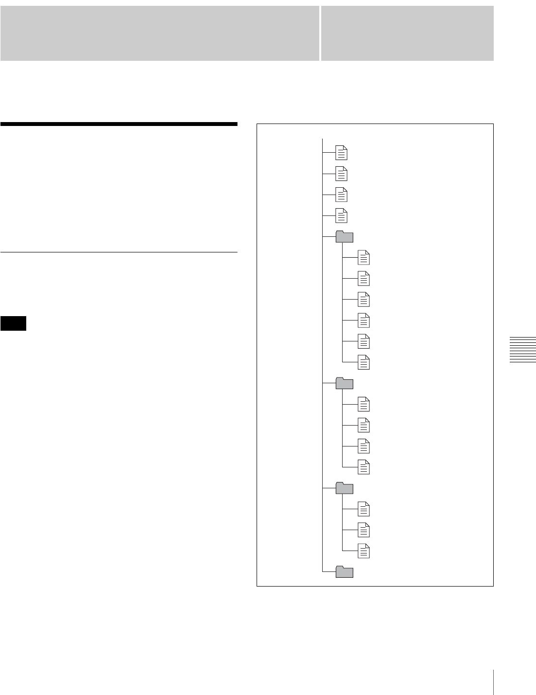
155
Overview
Chapter
Chapter 7 File Operation
7
File Operation
Overview
A remote computer can be connected to this unit and used
to operate on recorded data which has been saved in data
files, such as video and audio data files.
To connect a remote computer, use FAM (file access
mode) for the computer connection.
Directory Structure
The following figure shows the directory structure of discs
visible to a remote computer.
This structure is not the same as the actual structure
recorded on the disc.
a) Root directory
b) Only when sub item “NAMING FORM” on the FILE NAMING page of
the OPERATION menu is set to “FREE”.
Note
root a)
INDEX.XML
ALIAS.XML b)
Clip
Edit
Sub
General
DISCMETA.XML
MEDIAPRO.XML
C0001.MXF
C0001M01.XML
C0002.MXF
C0002M01.XML
C0003.MXF
C0003M01.XML
E0001E01.SMI
E0001M01.XML
E0002E01.SMI
E0002M01.XML
C0001S01.MXF
C0002S01.MXF
C0003S01.MXF
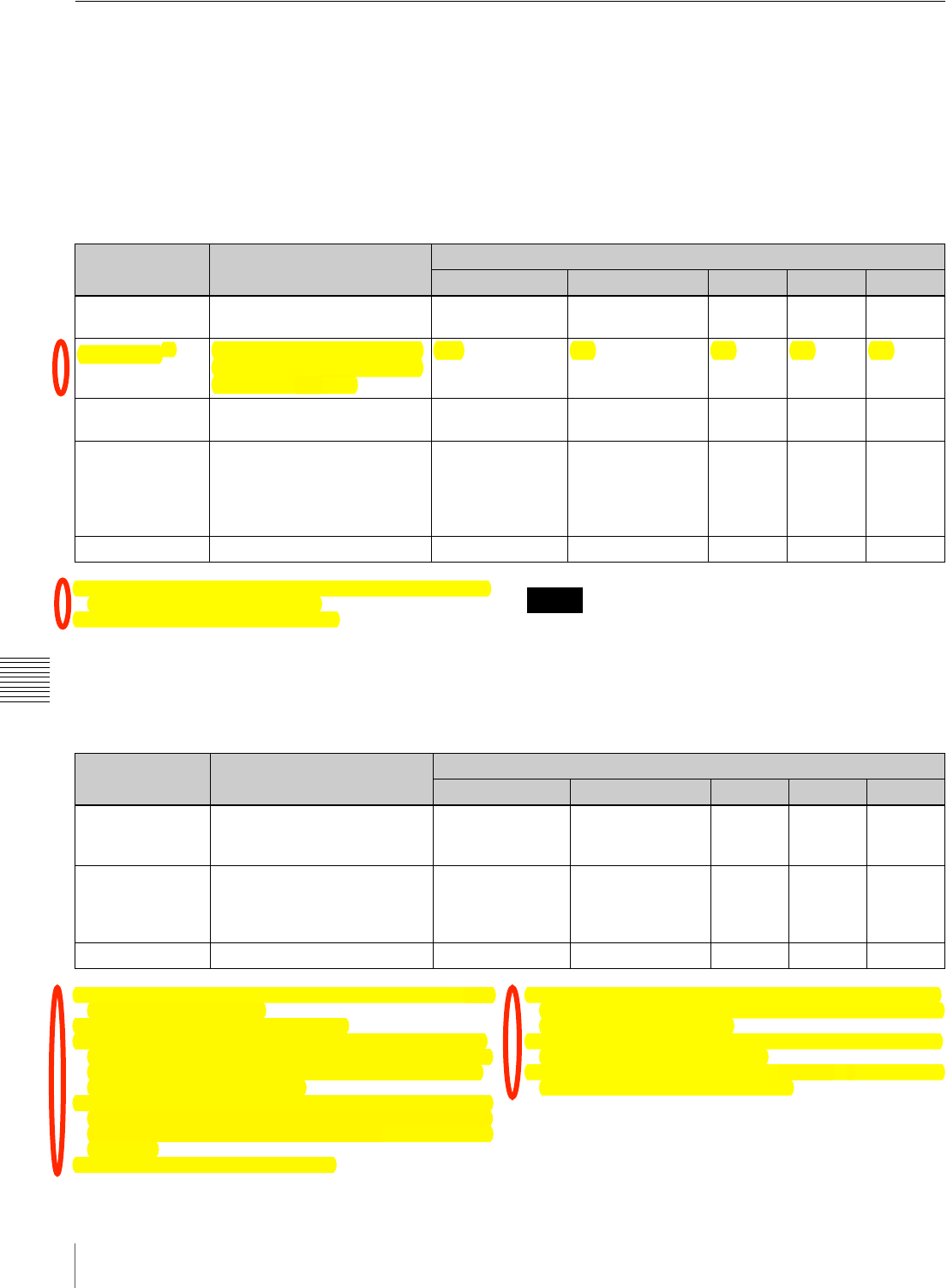
156 Overview
Chapter 7 File Operation
File Operation Restrictions
This section explains which operations are possible on
files stored in each directory.
When required, the following operation tables distinguish
reading and writing from partial reading and writing.
Read: Read data sequentially from the start to the end of
the file.
Partial read: Read only a part of the data in the file.
Write: Write data sequentially from the start to the end of
the file.
Partial write: Write data to a part of the file only.
Root directory
a) Only when sub item “NAMING FORM” on the FILE NAMING page of
the OPERATION menu is set to “FREE”.
b) Only files which can be written by XDCAM. • Directories cannot be created in the root directory.
• The directories in the root directory (Clip, Edit, Sub, and
General) cannot be deleted or renamed.
Clip directory
a) With firmware version 1.5 and higher, the unit can handle files with user-
defined names in the “C*” part.
b) Possible with firmware version 1.5 and higher.
c) Only files which are 2 seconds or longer in length, in a format matching
the format (system frequency) and recording format (MPEG HD/DVCAM
and number of audio channels) of the recorded sections of the disc, and
which can be overwritten by XDCAM.
d) Only when the Write Inhibit tab on the disc is set to enable recording. With
firmware version 1.1 and lower, only the most recently recorded clip may
be deleted. With firmware version 1.5 and higher, any clip may be selected
and deleted.
e) Only files which can be written by XDCAM
f) With firmware version 1.5 and higher, when the “C*” part of a C*.MXF
file name is changed, a C*M01.XML file with the same name in the “C*”
part is also changed automatically.
g) When a C*.MXF file is created, a C*M01.XML file with the same name
in the “C*” part is created automatically.
h) When a C*.MXF file is deleted, the C*M01.XML file with the same name
in the “C*” part is also deleted automatically.
File name Content Operations
Read/Partial read Write/Partial write Rename Create Delete
INDEX.XML Contains data for management
of the material on the disc. Yes No No No No
ALIAS.XML a) Contains conversion tables for
assigning user-defined names
to clips and clip lists.
Yes No No No No
DISCMETA.XML Contains metadata to indicate
the disc properties. Yes Yes b) No No No
MEDIAPRO.XML Contains a list of material on
the disc, basic properties,
related information, and
information about access
methods.
Yes No No No No
Other files Files other than the above – No – No –
Notes
File name Content Operations
Read/Partial read Write/Partial write Rename Create Delete
C*.MXF a) Clip file created by recording
(MXF file)
*: 0001 to 9999
Yes No No b) Yes c) Yes d)
C*M01.XML a) Metadata file generated
automatically when C*.MXF
file is created.
*: 0001 to 9999
Yes Yes e) No f) No g) No h)
Other files Files other than the above – No – No –
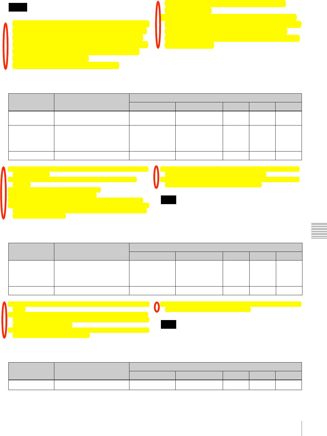
157
Overview
Chapter 7 File Operation
• Directories cannot be created in the Clip directory.
• When the following operations, supported by version 1.5
and higher XDCAM devices, are carried out on a disc,
then it becomes impossible for version 1.4 and lower
XDCAM devices to record new clips or delete existing
clips on that disc. (The only possible operations are
playback and disc formatting.)
- Writing of clips with user-defined names
- Deletion of clips (except the last recorded clip)
- Locking of clips
• If you attempt to write a C*.MXF file which does not
meet the conditions specified as remark c) on this table
via a FAM connection, a Windows error message
appears to the effect that the file or directory is corrupt
and cannot be read.
Edit directory
a) With firmware version 1.5 and higher, the “E*” part can be changed to a
user-defined name.
b) Only files which can be written by XDCAM. Partial writing is not
possible.
c) Possible with firmware version 1.5 and higher.
d) Only files which can be written by XDCAM
e) Only when the Write Inhibit tab on the disc is set to enable recording.
f) With firmware version 1.5 and higher, when the “E*” part of a *E01.SMI
is changed, an E*M01.XML file with the same name in the “E*” part is
also changed automatically.
g) When an E*E01.SMI file is created, an E*M01.XML file with the same
name in the “E*” part is also generated automatically.
h) When an E*E01.SMI file is deleted, an E*M01.XML file with the same
name in the “E*” part is also deleted automatically.
Directories cannot be created in the Edit directory.
Sub directory
a) With firmware version 1.5 and higher, the “C*” part can be changed to any
name.
b) With firmware version 1.5 and higher, when the “C*” part of a C*.MXF
file name is changed, a C*S01. MXF file with the same name in the “C*”
part is generated automatically.
c) When a C*.MXF file is created, a C*S01.XML file with the same name in
the “C*” part is generated automatically.
d) When a C*.MXF file is deleted, the C*S01.XML file with the same name
in the “C*” part is also deleted automatically.
Directories cannot be created in the Sub directory.
General directory
Notes
File name Content Operations
Read/Partial read Write/Partial write Rename Create Delete
E*E01.SMI a) Clip list file
*: 0001 to 0099 Yes Yes b) No c) Yes d) Yes e)
E*M01.XML a) Metadata file generated
automatically when E*E01.SMI
file is created.
*: 0001 to 0099
Yes Yes b) No f) No g) No h)
Other files Files other than the above – No – No –
Note
File name Content Operations
Read/Partial read Write/Partial write Rename Create Delete
C*S01.MXF a) Proxy AV data (MXF) file
generated automatically when
a C*.MXF file is created.
*: 0001 to 4999
Yes No No b) No c) No d)
Other files Files other than the above – No – No –
Note
File name Content Operations
Read/Partial read Write/Partial write Rename Create Delete
Any file – Yes Yes Yes a) Yes Yes b)

158 File Access Mode File Operations
Chapter 7 File Operation
a) UTF-8 file names can be up to 63 bytes in length. (Depending on the
character type, file names (including extension) may be limited to 21
characters.)
b) Only when the Write Inhibit tab on the disc is set to enable recording.
The following directory operations are possible in the
General directory.
• Directory creation (up to 64 levels, including the
General directory)
• Deletion and renaming of directories
• The maximum number of files that can be created on one
disc, including directories, is 5000.
• File names and directory names can use letters, numbers,
and symbols from the Unicode 2.0 (UTF-8) character
set.
However, the following control characters and
symbols 1) cannot be used.
- Control characters: U+0000 to U+001F, U+007F
- Symbols: ", *, /, :, <, >, ?, \, |
1) This is supported from firmware version 1.4. However, the following
character codes cannot be used by FAM connections. U+010000,
U+020000, U+030000, U+040000, U+050000, U+060000, 0U+70000,
U+080000, U+090000, U+0A0000, U+0B0000, U+0C0000, U+0D0000,
U+0E0000, U+0F0000, U+100000
File Access Mode File
Operations
File access mode operating environment
Operating system requirements for file operations by file
access mode (called FAM below) are as follows.
•Computer operating system: Microsoft Windows
2000 Service Pack 4 or higher, or Microsoft
Windows XP
Preparations
Install the FAM driver on the remote computer.
To install the FAM driver
Insert the supplied CD-ROM (PDZ-1 Proxy Browsing
Software) in the CD-ROM drive of the computer and
execute the Setup.exe file, then follow the installation
instructions.
For details, refer to the ReadMe file contained on the CD-
ROM disc.
Use Version 1.4 or higher of the FAM driver. The FAM
driver on the supplied CD-ROM is Version 1.4 or higher.
If a FAM driver is already installed on your computer,
check the version.
To check the version, click “Add or Remove
Programs”(Windows XP) or “Add/Remove Programs”
(Windows 2000), select “ProDisc”, and then click “Click
here for support information”.
Making FAM connections
Proceed as follows.
1
If there is a disc loaded in this unit, put the unit into the
following state.
• Recording, playback, search and other disc
operations: Stopped
• THUMBNAIL indicator (see page 21): Off
• Disc access by DELETE LAST CLIP, DELETE
ALL CLIPS, or QUICK FORMAT on the DISC
page of the OPERATION menu, and so on: Stopped
• Interval Rec function: Off
• MENU switch: OFF
• Unsaved current clip list: Save or clear
2
Connect the DV IN/OUT S400 connector on this
unit to the i.LINK (IEEE1394) connector on the
remote computer, using an i.LINK cable.
Notes
Note
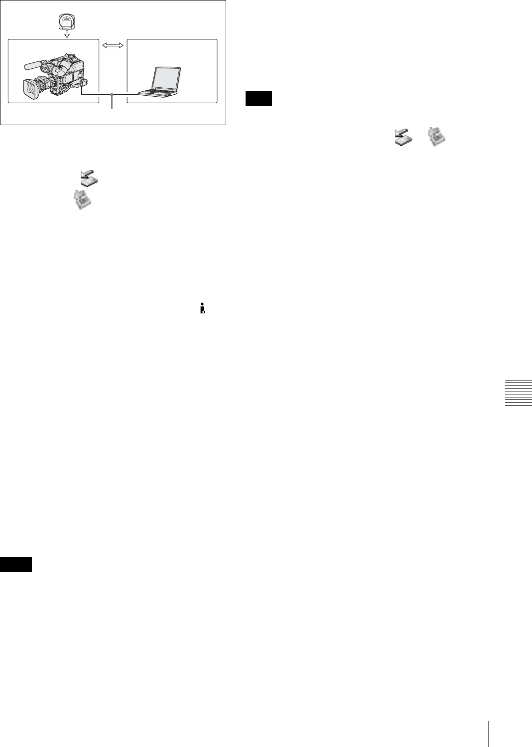
159
File Access Mode File Operations
Chapter 7 File Operation
Windows recognizes this unit as a removable disc, and
displays one of the following icons on the remote
computer’s task bar:
• Windows 2000:
• Windows XP:
The remote computer is now able to perform file
operations when a disc is inserted into this unit.
Operation limitations during FAM connections
• With the exception of the EJECT button, recording
buttons and playback control buttons are disabled.
• The VDR of this unit cannot be controlled from devices
connected to the REMOTE connector (8-pin) and DV
IN/OUT S400 (i.LINK) connector.
• There is no signal output from this unit while video is
being input to this unit from external equipment.
Operating on files
Proceed as follows.
1
Start Explorer.
Check that a drive letter has been assigned to this unit.
(The drive letter will differ depending on the number
of other peripherals connected to the remote
computer.)
2
Use Explorer to perform file operations on the disc
loaded in this unit.
You can operate in the same way that you operate on
local drives and files on network computers.
• If you power this unit off during an FAM
connection, the data transferred thus far is discarded.
• All file operations are not possible for some types of
files.
For details, see “File Operation Restrictions” on
page 156.
To eject discs from a remote computer
Right click the icon representing this unit in Explorer, and
select Eject from the menu which appears.
Exiting file operations
Proceed as follows.
Do not disconnect the cable before performing steps 1 to 3.
1
Do one of the following on the or icon
displayed in the remote computer’s taskbar.
• Double click.
• Right click, and select one of the following
commands from the menu which appears.
-Windows 2000: Unplug or Eject Hardware
-Windows XP: Safely Remove Hardware
The Unplug or Eject Hardware dialog box (Windows
2000) or Safely Remove Hardware dialog box
(Windows XP) appears.
2
Select “Sony XDCAM PDW-F330 (or PDW-F350)
IEEE 1394 SBP2 Device” and click Stop.
The Stop a Hardware device dialog appears.
3
Select “Sony XDCAM PDW-F330 (or PDW-F350)
IEEE 1394 SBP2 Device” and click OK.
In Windows 2000, a confirmation message appears.
In Windows XP, “Sony XDCAM PDW-F330 (or
PDW-F350) IEEE 1394 SBP2 Device” is deleted from
the list of hardware devices.
This unit can now resume normal operations. (The
limitations described in “Operation limitations during
FAM connections” on page 159 no longer apply.)
4
Disconnect the i.LINK cable as required.
Reconnecting
To reconnect after exiting file operations, do one of the
following, depending on whether an i.LINK cable is
connected.
i.LINK cable is not connected: Connect this unit and a
remote computer with an i.LINK cable.
i.LINK cable is connected: Disconnect the i.LINK cable
from either this unit or the remote computer, wait for
at least 10 seconds, and then reconnect the
disconnected cable.
The unit is powered off and an i.LINK cable is
connected: Power the unit on.
Notes
File data
Transfer of files
PDW-F330/F330P/
F350/F350P Laptop computer, etc.
i.LINK cable (not supplied)
Note

160 Important Notes on Operation
Appendix
Appendix
Important Notes on
Operation
Use and Storage
Do not subject the unit to severe shocks
The internal mechanism may be damaged or the body
warped.
Do not cover the unit while operating
Putting a cloth, for example, over the unit can cause
excessive internal heat build-up.
After use
Always turn off the POWER switch.
Before storing the camcorder for a long period
Remove the battery pack.
Shipping
• Remove the disc before transporting the unit.
• If sending the unit by truck, ship, air or other
transportation service, pack it in the shipping carton of
the unit.
Care of the unit
Remove dust and dirt from the surfaces of the lenses or
optical filters using a blower.
If the body of the unit is dirty, clean it with a soft, dry cloth.
In extreme cases, use a cloth steeped in a little neutral
detergent, then wipe dry. Do not use organic solvents such
as alcohol or thinners, as these may cause discoloration or
other damage to the finish of the unit.
In the event of operating problems
If you should experience problems with the unit, contact
your Sony dealer.
Use and storage locations
Store in a level, ventilated place. Avoid using or storing the
unit in the following places.
• In excessive heat or cold (operating temperature range:
0°C to 40°C (32°F to 104°F))
Remember that in summer in warm climates the
temperature inside a car with the windows closed can
easily exceed 50°C (122°F).
• In damp or dusty locations
• Locations where the unit may be exposed to rain
• Locations subject to violent vibration
• Near strong magnetic fields
• Close to radio or TV transmitters producing strong
electromagnetic fields.
• In direct sunlight or close to heaters for extended periods
To prevent electromagnetic interference from
portable communications devices
The use of portable telephones and other communications
devices near this unit can result in malfunctions and
interference with audio and video signals.
It is recommended that the portable communications
devices near this unit be powered off.
Note on laser beams
Laser beams may damage the CCDs.
If you shoot a scene that includes a laser beam, be careful
not to let the laser beam be directed into the lens of the
camera.
Use at a high temperature
If the unit is used at a high temperature, white flecks may
appear on the screen.
Fitting the zoom lens
It is important to fit the lens correctly, as otherwise damage
may result. Be sure to refer to the section “Mounting the
Lens” on page 40.
Viewfinder
• Do not leave the unit with the eyepiece pointing directly
at the sun.
The eyepiece lens can concentrate the sun’s rays and
melt the interior of the viewfinder.
• Do not use the viewfinder close to strong magnetic
fields. This can cause picture distortion.

161
Important Notes on Operation
Appendix
About the LCD panels
LCD panels are manufactured with extremely high-
precision technology that yields effective pixel rates of
99.99% or higher. However, very rarely, one or more
pixels may be permanently dark or permanently lit in
white, red, blue, or green.
This phenomenon is not a malfunction. Such pixels have
no effect on the recorded data, and the unit may be used
with confidence even if they are present.
Phenomena Specific to CCD Image
Sensors
The following phenomena that may appear in images are
specific to CCD (Charge Coupled Device) image sensors.
They do not indicate malfunctions.
White flecks
Although the CCD image sensors are produced with high-
precision technologies, fine white flecks may be generated
on the screen in rare cases, caused by cosmic rays, etc.
This is related to the principle of CCD image sensors and
is not a malfunction.
The white flecks especially tend to be seen in the following
cases:
• when operating at a high environmental temperature
• when you have raised the master gain (sensitivity)
• when operating in Slow-Shutter mode
This problem may be alleviated by automatic black
balance adjustment (see page 59).
Vertical smear
When an extremely bright object, such as a strong spotlight
or flashlight, is being shot, vertical tails may be produced
on the screen, or the image may be distorted.
Aliasing
When fine patterns, stripes, or lines are shot, they may
appear jagged or flicker.
Condensation
If you move the camcorder from a very cold place to a
warm place, or use it in a damp location, condensation may
form on the optical pickup. Then, if the camcorder is
operated in this state, recording and playback may not be
performed properly.
Do the following to prevent this from happening.
• When you move or operate the camcorder in an
environment where condensation may form, be sure to
insert a disc in advance and close the disc compartment
lid.
• Whenever you turn on the POWER switch, check that
the HUMID indicator does not appear on the LCD
monitor. If it appears, wait until it disappears before
inserting a disc.
Vertical tails shown on the
image.
Monitor screen
Bright object (e.g. strong
spotlight, strong reflected
light, flashlight, the sun)
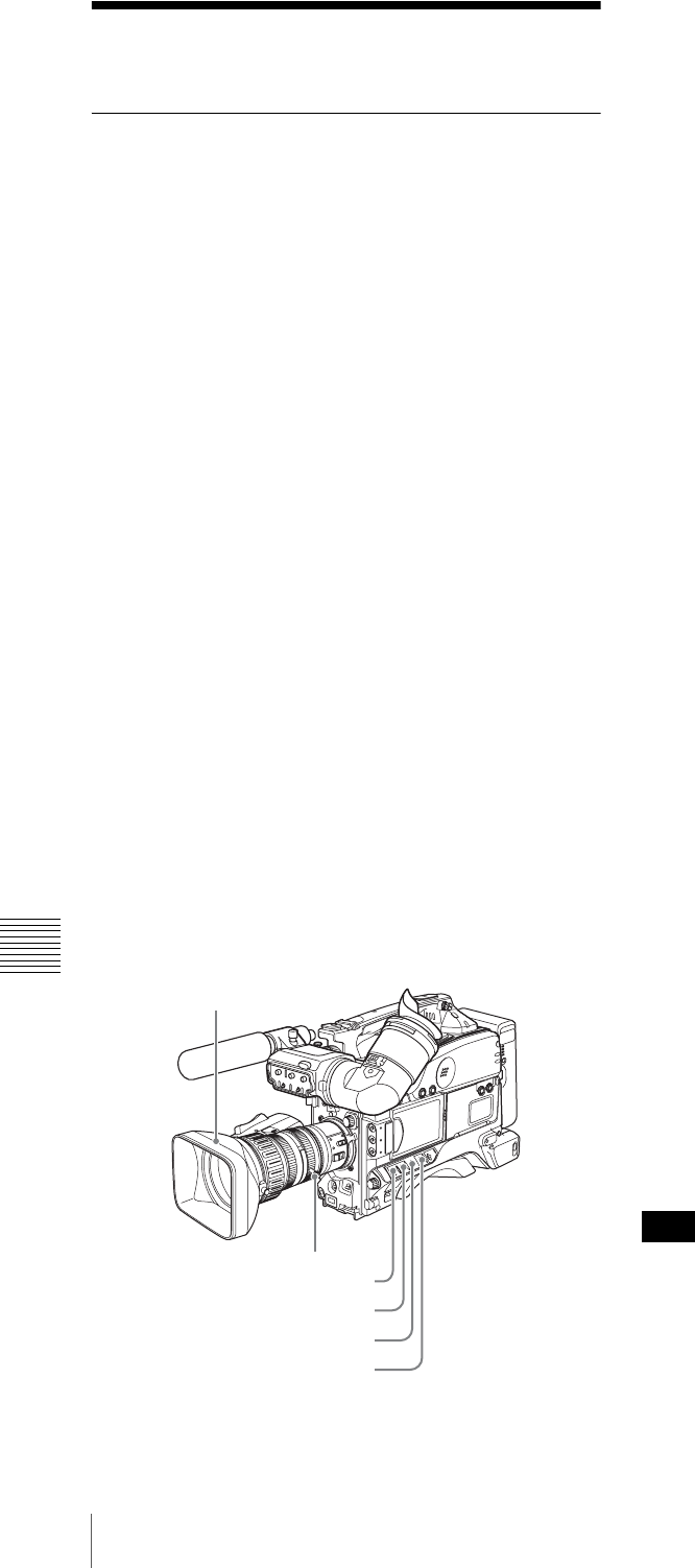
162 Maintenance
Appendix
Maintenance
Testing the Camcorder Before
Shooting
Check the functions of the camcorder before setting out for
a shooting session, preferably by operating the camcorder
together with a color video monitor.
Preparations for testing
1
Attach a fully charged battery pack.
2
Set the POWER switch to ON and check that the
HUMID indicator does not appear and that the
remaining battery capacity indicator shows at least
five segments.
• If the HUMID indicator appears, wait until it
disappears (see page 161).
• If the remaining battery capacity indicator does not
show at least five segments, replace the battery pack
with a fully charged one.
3
Check that there are no obstructions near the disc
compartment, and then press the EJECT button to
open the disc compartment lid.
4
After confirming that the disc is not write-protected,
load the disc and close the disc compartment lid.
Testing the Camera
Set the switches and selectors as follows.
Testing the viewfinder
1
Adjust the position of the viewfinder.
2
Check that the color bars are displayed on the
viewfinder screen, and adjust the BRIGHT,
CONTRAST, and PEAKING controls to give the best
color bar display.
3
Check the following points in the listed order.
• The menu is displayed on the viewfinder screen.
• Turn the MENU knob and check that the menu page
changes to the next page.
• Press the MENU knob and check that settings of
each item of the selected page are displayed.
• Turn the MENU knob and check that the b mark
moves within the page.
• Press the MENU knob and check that the b mark
placed before the item changes to a z mark and the
z mark placed before the setting of the item changes
to a ? mark.
• Turn the MENU knob and check that the setting of
the selected item changes.
4
Set the OUTPUT/DCC switch to CAM, and change
the FILTER selector position in the sequence of 1, 2, 3
and 4.
Check that the FILTER indicator on the viewfinder
screen displays the correct numbers.
5
Move the SHUTTER switch from ON to SEL
repeatedly, and check that the shutter setting changes
on the viewfinder screen.
6
Pointing the camera at a suitable subject, focus the
camera and check the picture on the viewfinder screen.
7
Set both of the AUDIO IN switches to FRONT, and
check that when sound is input to a microphone
connected to the MIC IN connector on the front of the
camcorder, the audio level indicators appear on the
viewfinder screen.
8
Check that setting the ZEBRA switch to ON and OFF
makes the zebra pattern appear and disappear on the
viewfinder screen.
The results of checking in steps 3 to 8 may not be as
expected, depending on the settings relating to the
viewfinder display function. In this case, set the desired
items on the VF DISP 1 and VF DISP 2 pages of the
OPERATION menu.
Iris: A (auto)
Zoom: SERVO/MANU.
VDR SAVE/STBY: SAVE
GAIN: Set as low as possible
WHITE BAL: A or B
OUTPUT/DCC: BARS
Note

163
Maintenance
Appendix
For details, see “Selecting the Display Items” on
page 136.
Testing the iris and zoom functions
1
Set the zoom to automatic zoom mode and check that
the power zoom operates correctly.
2
Set the zoom to manual zoom mode and check the
zoom functions manually. Turn the manual zoom lever
from the telephoto position to the wide-angle position
to check that the picture changes depending on the
lever position.
3
Set the IRIS switch on the lens to A (auto) and point
the camera at objects of different brightness. Check
that the automatic iris adjustment operates correctly.
4
Set the IRIS switch on the lens to M (manual) and
check that turning the iris ring manually adjusts the iris
correctly.
5
Set the IRIS switch on the lens back to A (auto) and
check the following points when the GAIN switch is
moved from L to M to H.
• For objects of the same brightness, the iris is
adjusted to correspond to the change in setting.
• The gain indicator on the viewfinder screen changes
to correspond to the change in setting.
6
When a lens with extender is mounted, set the lens
extender lever to the 2x position and check that auto
iris functions correctly.
Testing the VDR
Continuously carry out the procedures from “(1) Testing
the recording and playback functions” to “(6) Checking the
user bit and timecode functions” described below.
(1) Testing the recording and playback functions
1
Using the following buttons in the LCD monitor,
display the text information.
DISPLAY/EXPAND button: CHAR
COUNTER/CHAPTER button: COUNTER
BRIGHT button: adjustment of backlight brightness
2
Set the PRESET/REGEN/CLOCK switch to PRESET,
and set the F-RUN/SET/R-RUN to R-RUN.
3
Press the REC button and check the following points.
• The time counter indication in the LCD monitor
changes.
• The REC indicator in the viewfinder is on.
• The RF and SERVO indicators on the LCD monitor
are off.
4
Press the REC button again.
Check that recording stops and that the REC indicator
in the viewfinder goes off.
5
Repeat the checks of steps 3 and 4, this time using the
REC button on the lens.
Press the RESET button and check that the indication
in the time counter display section of the LCD
monitor.
6
Press the F REV button and check that fast reverse
playback is performed. Next, press the PLAY/PAUSE
button and check that normal playback is performed.
7
Press the STOP button and check that playback stops.
Next, press the F FWD button and check that fast
forward playback is performed.
8
Press the STOP button again, then press the PREV
button.
Check that the image of the beginning of the current or
previous clip is displayed.
9
Press the NEXT button, and check that the image of
the beginning of the next clip is displayed.
(2) Testing the automatic audio level adjusting
functions
1
Set both AUDIO IN CH-1 and CH-2 switches to
FRONT.
2
Set both AUDIO SELECT (CH-1 and CH-2) switches
to AUTO.
3
Set both AUDIO IN CH-3 and CH-4 switches to F
(front).
4
Aim the microphone connected to the MIC IN
connector at a suitable sound source.
Check that the level indications for channels 1 to 4
correspond to the sound level, respectively.
(3) Testing the manual audio level adjusting functions
1
Set both AUDIO IN CH-1 and CH-2 switches to
FRONT.
2
Turn the MIC LEVEL control.
Check that the channel-1 and -2 audio level meters on
the LCD monitor shows no segment when you fully

164 Maintenance
Appendix
turn the control counterclockwise as seen from the
camcorder front.
(4) Testing the earphone and speaker
1
Turn the MONITOR knob and check that the speaker
volume changes accordingly.
2
Connect an earphone to the front or rear EARPHONE
jack.
Check that the speaker sound is cut off and that you
can hear the sound from the microphone in the
earphone.
3
Turn the MONITOR knob and check that the earphone
volume changes accordingly.
(5) Testing external microphones
1
Connect external microphones to the AUDIO IN CH-
1 and CH-2 connectors.
2
Set the +48V/OFF switches as follows.
• If the connected microphone is of the internal power
supply type, set the switch to OFF.
• If the connected microphone is of the external power
supply type, set the switch to +48V.
3
Set the AUDIO IN switches to REAR.
4
Aim the microphones at a sound source.
5
Check that the audio level meters in the LCD monitor,
and the audio level indications in the viewfinder
change with the volume of the sound.
(6) Checking the user bit and timecode functions
1
Set the user bits as required.
For the operation, see “To set the user bits” on
page 67.
2
Set the timecode.
For the operation, see “To set the timecode” on
page 66.
3
Set the F-RUN/SET/R-RUN switch to R-RUN.
4
Press the REC button, and check that recording starts
and that the timecode indication in the time counter
display section changes.
5
Press the REC button again, and check that recording
stops and that the timecode indication stops changing.
6
Set the F-RUN/SET/R-RUN switch to F-RUN, and
check that the timecode indication starts changing
again and continues to change even when you restart
recording and stop recording again.
7
Set the COUNTER/CHAPTER button to U-BIT, and
check that the user bits data that was set is displayed.
Maintenance
Cleaning the viewfinder
Use a dust blower to clean the CRT screen and mirror
inside the viewfinder barrel.
Clean the lens and protecting filter with a commercially
available lens cleaner.
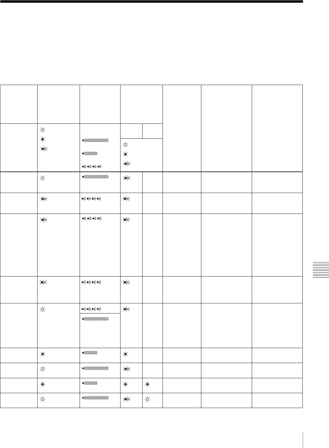
165
Operation Warnings
Appendix
Operation Warnings
When a problem occurs at power on or during operation, a
warning is given by one of the following.
• Warning indicators in the status display on the LCD
monitor
• WARNING indicators, and audible warnings from the
speaker and earphones
• Indicators on the viewfinder
The volume of the audible warnings can be adjusted with
the ALARM knob. Set the ALARM knob to the minimum
position to suppress the sound.
Status
display on
the LCD
monitor/
viewfinder
screen
WARNING
indicator
Warning
sound
Indicators in
the viewfinder
Problem VDR operation Action to take
Warning
indication
: Continuous
: 1 flash/s
: 4 flashes/s
Continuous
beep
1 beep/s
4 beeps/s
REC/
TALLY
BATT
: Continuous
: 1 flash/s
: 4 flashes/s
E**-** 1) – Recording
error Recording stops. Turn off the power
and consult your
Sony dealer.
MEM Full! 2) 2) 2) – Shockproof
memory
overflow
Recording
continuous but may
be substandard.
Protect the unit
from shocks and
vibration.
ILL.REC! 2) 2) 2) – Input sync
error Recording
continuous but may
be substandard.
Turn off the power
and contact your
Sony dealer. (This
indication may be
given momentarily
when a GENLOCK
signal is connected
or disconnected,
but this does not
indicate a problem.)
Disc Error! 2) 2) 2) – A disc defect
was detected. Recording
continues, avoiding
the defect, but may
be substandard.
If defects are
detected
repeatedly,
exchange the disc.
HUMID! 2) 2) 2) – Condensation
on the optical
pickup.
Recording/playback
continues but stops
when an error
occurs on the drive.
Stop recording/
playback, turn off
the power, then turn
it on again, and wait
until the HUMID
indicator
disappears.
3)
Before Full 2) 2) 2) – Disc almost
full. Operation
continues. Be prepared to
change the disc.
DISC
FULL! 4) 4) 4) 4) – Disc full. Recording stops. Change the disc.
LOW BATT! 2) 5) 5) Battery almost
exhausted. Operation
continues. Change the battery.
BATT
EMPTY! Battery
exhausted. Operation stops. Change the battery.
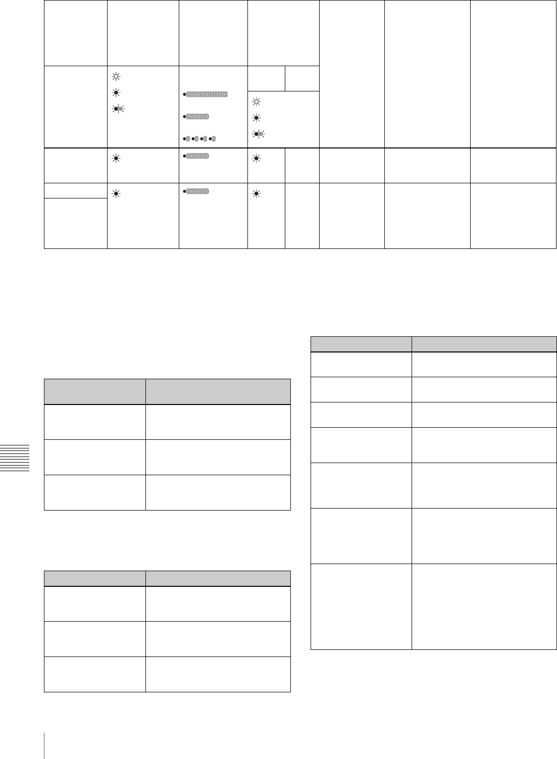
166 Operation Warnings
Appendix
1) Asterisks (*) are replaced by digits in the display.
2) During recording
3) During playback, fast forward, fast reverse, or stop
4) During recording pause
5) During recording or pause
For details about the warning displays and alarm
messages on the viewfinder, see the next item.
Operation/alarm messages
An operation or alarm message is displayed in the
operation/alarm message display area (see page 32) of the
viewfinder screen.
A message for VDR operation is displayed in the setting
change and adjustment progress message display area of
the viewfinder screen (see page 32).
High TEMP! – Internal
temperature
high.
Operation
continues. Power the unit off
and move it to a
cool place.
ACC Sensor! – Internal drive
sensor error Operation
continues. Protect the unit
from shock and
vibrations, turn off
the power, and
contact your Sony
dealer.
Skew Sensor
Status
display on
the LCD
monitor/
viewfinder
screen
WARNING
indicator
Warning
sound
Indicators in
the viewfinder
Problem VDR operation Action to take
Warning
indication
: Continuous
: 1 flash/s
: 4 flashes/s
Continuous
beep
1 beep/s
4 beeps/s
REC/
TALLY
BATT
: Continuous
: 1 flash/s
: 4 flashes/s
Operation/alarm
message
Meaning
INTERVAL **M**S Indicates the camera is in the
Interval Rec mode. **M**S
indicates the shooting interval.
LOW LIGHT Appears, depending on the
setting, to indicate the subject
illumination is inadequate.
HIGH TEMPERATURE Indicates that temperatures have
risen inside the unit. Avoid
continued use in this state.
Message Meaning and action to take
ILL. Disc! The disc cannot be used by this
unit. Insert another Professional
Disc.
ILL. Index!
No FS!
Unknown FS!
Index file or file system error.
Exchange or format the disc.
No Support! A recorded clip cannot be handled
by this unit. Exchange or format
the disc.
FORMAT NG! The disc cannot be used by this
unit. Exchange the disc.
Disc Damage The disc cannot be recorded. To
record, exchange the disc.
Non AV Full
MAX # Files The disc is full. Exchange or
format the disc.
DI read err
Read err
DRV ADJ err
The disc was not recognized. Try
ejecting the disc and inserting it
again. Or exchange the disc.
Run Salvage Salvage processing needs to be
done on the disc. To record on the
disc, eject the disc, insert it again,
and execute salvage processing.
Salvage NG Salvage processing failed. +,-$
.#/&01"2$"##$5]&7.107'$,N$P0"8"$
L3#7$F#8,-.07'$P,#"$U,/$\7.$
U,-9&11W$!C&1J&'#$+K78/0,7*:$,7$
%&'# )>.
REC INHI.! The Write Inhibit tab of the disc is
in the recording disabled position,
or salvage processing needs to be
done on the loaded disc. Set the
tab to the recording enabled
position. Or eject the disc, insert it
again, and perform salvage
processing.
Message Meaning and action to take

167
Operation Warnings
Appendix
a) REC INHI.! appears if you attempt to start recording.
Alarm messages during thumbnail search,
scene selection, and clip list operations
Alarm messages may appear in the LCD monitor during
thumbnail search, scene selection, and clip list operations.
In this case, take the action indicated in the following table.
HD 50I/25P
HD 60I/30P
HD 23P Disc
525/60
625/50
2CH×16 Clip
4CH×16 Clip
The loaded disc has a different
recording format. Exchange the
disc, or change the recording
format.
Index File! There is an unsupported index file
on the disc to which you are trying
to record. Exchange or format the
disc.
File System There is an unsupported file
system on the disc to which you
are trying to record. Exchange or
format the disc.
KEY INHI.! a) Disc operations are not possible
when the DC IN connector is not
connected and the CA-755 is
being used.
ILL. PLAY! An A/V phase error occurred
during playback. Stop the disc.
Lid Closed! The lid of the disc compartment
does not open. Check the lid.
Lid Open! The lid of the disc compartment is
not closed. Close it securely.
No Clip! There are no clips recorded on the
disc. Exchange for a recorded
disc.
No Disc! There is no disc loaded. Insert a
disc and try the operation again.
STOP ONCE!
REC mode! The operation is not possible while
the disc is being played or
recorded. Stop the disc.
Disc Top!
Disc End! The operation is not possible
because the disc is at the top or
end.
Formatting! The disc is being automatically
formatted. Wait until the format
ends.
Recording The unit is writing to the file
system. Wait until writing finishes.
No EM Space
EM Full! Essence marks cannot be
inserted. +,-$.#/&01"2$"##$
5F#8,-.07'$C3,/$[&-=":$,7$
%&'# AE;
SB CLP mode Press the SEL/SET button (four-
way arrow key) up to clear the
SUB CLIP indicator before
carrying out the operation.
No SEL List No clip list is selected. Create a
new clip list, or load a clip list from
the disc.
No List! There is no clip list. Create a clip
list.
No SUB Clip There are no sub clips in the clip
list. Register a sub clip, or load
another clip list.
Message Meaning and action to take
SUB Clip NG The In and Out point positions are
invalid. Set correct In and Out
points.
MAX# SB CLP The total number of sub clips is
over the upper limit (300).
CL OVER DUR The total duration of sub clips in
the current clip list is over the
upper limit (24 hours).
FAN Stopped!
DR-FAN Stop The main unit or drive fan has
stopped. Avoid use under high
temperatures, turn off the power,
and contact your Sony dealer.
Message Meaning and action to take
CANNOT EXPAND
CLIP
ANY FURTHER.
The clip cannot be expanded into
more blocks.
This appears when the EXPAND
button is pressed when the
number of block is maximum, or
when the duration of an expanded
thumbnail is 1 frame.
SELECTED ESSENCE
MARK
DOES NOT EXIST.
The selected essence mark does
not exist.
This appears in the essence mark
selection screen when the
specified essence mark does not
exist on the disc.
SUB CLIP IS INVALID.
SET APPROPRIATE
IN/OUT POINTS.
The temporal relationship between
the specified In and Out points in a
TRIM operation !"##$%&'#$?A* is
not correct.
Reset so that the value of the Out
point timecode is larger than the
value of the In point timecode.
DURATION OF ONE
CLIP LIST MUST BE
LESS THAN 24
HOURS.,
The total duration of the current
clip list is greater than 24 hours.
This appears when the total
duration of the current clip list
exceeds the upper limit of 24
hours as the result of a sub clip
ADD$!"##$%&'#$?@* operation or a
TRIM operation !"##$%&'#$?A*.
NO MORE SUB CLIPS
CAN BE ADDED TO
THE CLIP LIST.
The upper limit of sub clips in the
current clip list has been
exceeded.
This appears when the total
duration of the current clip list
exceeds the upper limit of 24
hours as the result of a sub clip
ADD$!"##$%&'#$?@* operation or a
TRIM operation !"##$%&'#$?A*.
Message Meaning and action to take

168 Operation Warnings
Appendix
SUB CLIP DOES NOT
EXIST. There are no sub clips in the
current clip list.
This appears when an attempt is
made to execute a MOVE !"##$
%&'#$?A*, TRIM !"##$%&'#$?A*,
DELETE !"##$%&'#$?B*, or TC
PRESET operation !"##$%&'#$??*
with no sub clips in the current clip
list.
CLIP LIST DOES NOT
EXIST. There are no clip lists on the disc.
This appears when an attempt is
made to execute a DELETE CLIP
LIST operation !"##$%&'#$DED*
when there are no clip lists on the
disc.
MOVE IS INVALID. The sub clip cannot be moved.
This appear hen an attempt is
made to execute a MOVE
operation !"##$%&'#$?A* when
there are no sub clip in the current
clip list, or when there is only 1.
SHOT MARK DOES
NOT EXIST. The specified shot mark has not
been recorded.
This appears when an attempt is
made to execute a DELETE SHOT
MARK operation on a clip when
the specified shot mark has not
been recorded for that clip.
REC START CANNOT
BE DELETED. REC START cannot be deleted.
This appears when an attempt is
made to delete a REC START with
a DELETE SHOT MARK
operation. DELETE SHOT MARK
can delete only SHOT MARK1 and
SHOT MARK2 marks.
CLIP IS LOCKED. The clip is locked.
This appears when an attempt is
made to delete a clip, set the clip
thumbnail, or delete a shot mark
when the clip is locked.
ALL CLIPS ARE
LOCKED. All clips are locked.
This appears when an attempt is
made to execute a LOCK ALL
CLIPS operation when all clips are
already locked.
ALL CLIPS ARE
UNLOCKED. All clips are unlocked.
This appears when an attempt is
made to execute an UNLOCK ALL
CLIPS operation when all clips are
already unlocked.
Message Meaning and action to take

169
Troubleshooting
Appendix
Troubleshooting
You can use this chart to establish possible causes of an
apparent problem; always double-check before sending
the camcorder for repair. If a problem persists, contact
your Sony dealer.
Symptoms Cause Remedy
The camcorder does not power on
when you set the POWER switch to
ON.
There is no battery pack attached. Attach a battery pack !"##$%&'#$@>*.
The battery pack is exhausted. Replace the battery pack with a fully charged
one !"##$%&'#$@>*.
The AC adaptor is not connected. Connect the AC adaptor !"##$%&'#$@>*.
Recording does not start when you
press the REC button. The POWER switch is set to OFF. Set the POWER switch to ON.
The disc has the Write Inhibit tab in the
recording disabled position. Set the Write Inhibit tab to allow recording
!"##$%&'#$)R*, or change the disc.
The disc is full. Replace the disc with one with sufficient free
space, or format the disc !"##$%&'#$))*.
The inserted disc requires salvage
processing. Carry out salvage processing !"##$%&'#$)>*.
The recording format setting is different
from that of the already recorded clips. Change the disc, or change the recording
format !"##$%&'#$)B*.
Playback does not start when you
press the PLAY button. The unit is stopped at the position after
recording finished. Press the PREV button to move to the first
frame of a clip, or hold down the PLAY/
PAUSE button and press the PREV button to
move to any other position.
The power supply cuts while
operating. The battery pack is exhausted. Replace the battery pack with a fully charged
one !"##$%&'#$@>*.
The battery goes dead very quickly. The operating temperature is very low. Use a BP-GL95 !"##$%&'#$@>*.
The battery pack is inadequately charged. Recharge the battery pack !"##$%&'#$@>*.
It is not possible to eject the disc. The battery pack is exhausted. Replace the battery pack with a fully charged
one !"##$%&'#$@>*.
If the battery cannot be charged, or there is
no replacement battery, use the procedure in
the next item, “To eject the disc when there is
no power supply” to eject the disc.
The POWER switch is set to OFF. Set the POWER switch to ON.
The playback picture quality is poor.
The playback picture does not
appear.
The playback sound does not hear.
The disc surface is scratched, or there is
dirt or dust adhering to the disc. Replace the disc.
The recording surface of the disc has
deteriorated over time.
The laser diode has deteriorated. In the HOURS METER page of the
DIAGNOSIS menu, check the cumulative
light output parameters of the optical head
!"##$%&'#$D(?*.
All controls except the EJECT
button are disabled. There is condensation. Remove the disc and wait with the power on
until the condensation has evaporated.
Audio recording is not possible. The AUDIO LEVEL (CH-1/CH-2) knobs
are set to the minimum level. Adjust the setting of the AUDIO LEVEL
knobs !"##$%&'#$DR*.
Audio recording is not possible (CH-
1 only). The AUDIO LEVEL knob on the front is set
to the minimum level. Adjust the setting of the AUDIO LEVEL knob
on the front !"##$%&'#$(E*.
The recorded sound is distorted. The audio level is too high. Adjust the setting of the AUDIO LEVEL
knobs, and record again !"##$%&'#$(E*.
The recorded sound has a high
noise level. The audio level is too low. Adjust the setting of the AUDIO LEVEL
knobs, and record again !"##$%&'#$(E*.
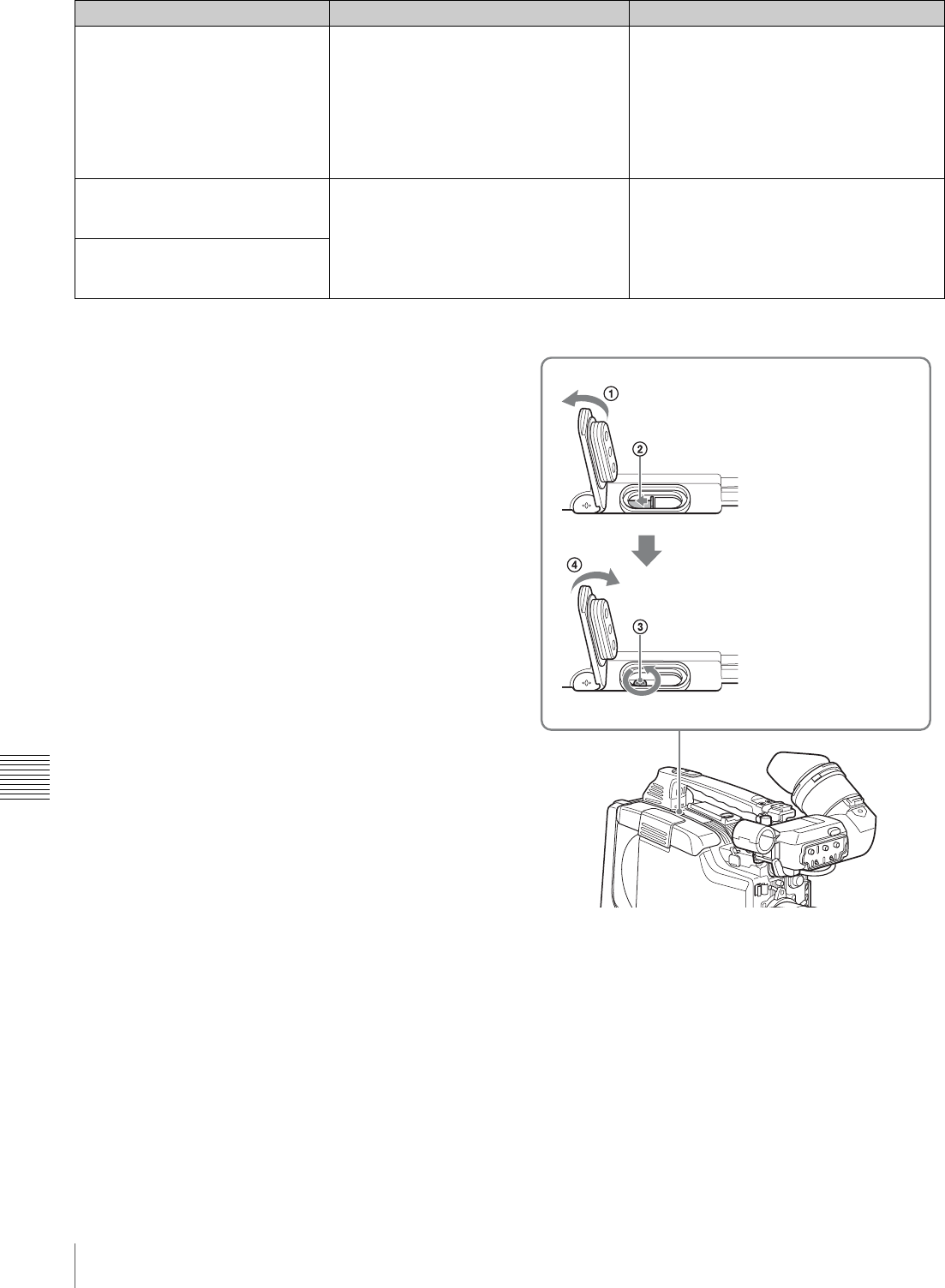
170 Troubleshooting
Appendix
To eject the disc when there is no power supply
When the battery is exhausted, for example, pressing the
EJECT button does not operate the disc ejection
mechanism. In such cases, as an emergency measure you
can remove the disc manually using the following
procedure.
1
Turn off the power supply to the unit.
2
Carry out the following operations.
After removing the disc, it is not necessary to return the
screw to its original position. When the power supply is
restored, the mechanism will again function normally.
The equipment connected to the
camcorder via an i.LINK connection
does not react as expected, for
example, the video image does not
appear on its screen.
It sometimes takes time for the connected
equipment to recognize the operation. Wait for about 15 seconds. If the connected
equipment still does not react, do the
following.
• Check the i.LINK cable, for example, by
re-plugging the i.LINK cable.
• Turn the power off, and connect the cable
again.
• Change the i.LINK cable.
The camera is not recognized by
the computer connected via i.LINK
interface.
There is a problem with the software, for
example, it does not support the MPEG
HD/DVCAM format, etc.
Install software that supports the MPEG HD/
DVCAM format.
The camera cannot be controlled by
the computer connected via i.LINK
interface.
Symptoms Cause Remedy
1Open the rubber cap to
reveal an access hole.
2With a screwdriver or
similar instrument, slide
the black metal plate in the
access hole toward the
rear of the unit.
The lid of the disc
compartment opens. The
red-colored cross
recessed head screw can
be seen in the access
hole.
3Use a Phillip type
screwdriver to turn the red
screw counterclockwise
(in the direction shown on
the rubber cap). This
ejects the disc.
4Replace the rubber cap
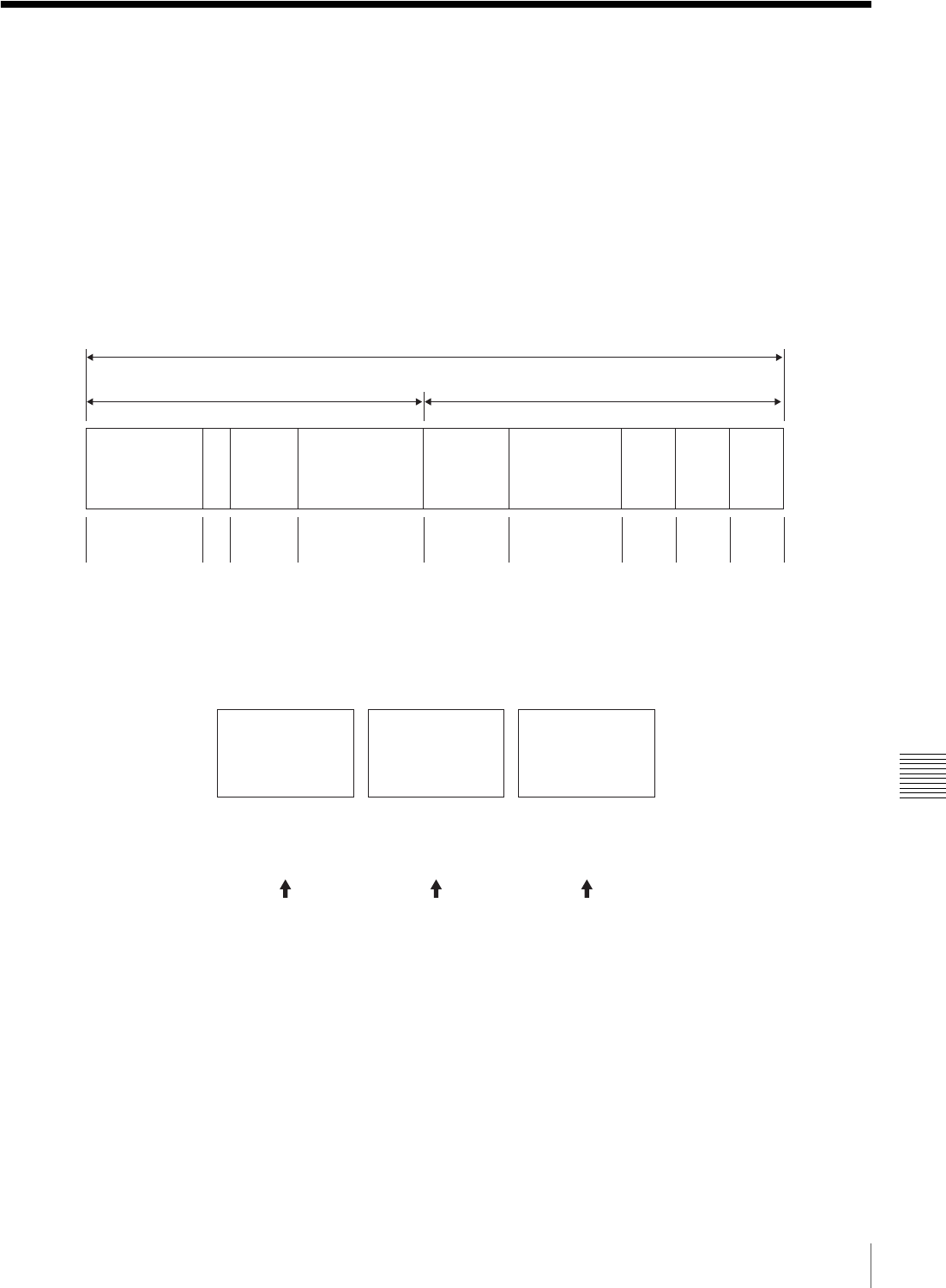
171
Using UMID Data
Appendix
Using UMID Data
To perform operations from interviewing to editing
effectively and to detect audio-visual materials easily
when reusing them, metadata that provides additional
information is recorded along with audio-visual data on a
disc.
As one of application of metadata, the UMID (Unique
Material Identifier) is internationally standardized.
What is a UMID?
The UMID (Unique Material Identifier) is a unique
identifier for audio-visual material defined by the
SMPTE330M-2003 standard.
The UMID may be used either as the 32-byte Basic UMID
or as the Extended UMID, which includes an additional 32
bytes of Source Pack to make a total 64 bytes.
For details, refer to SMPTE 330M.
Globally unique ID is automatically recorded every
shooting.
The Extended UMID is metadata that provides additional
information such as location, time/date, company and so
on.
The UMID is applied as follows.
Using the Extended UMID
You have to enter a country code, organization code and
user code. Set the country code referring to the ISO 3166
table, and set the organization code and user code
independently.
For details, see “Additional information related to the
UMID” on page 172.
Functions of UMID data
The UMID data enables the following:
Spatial
Coordinates
Extended UMID (64 bytes)
Basic UMID (32 bytes) Source pack (32 bytes)
Universal label L Instance
No. Material Number Time/Date UserCountry Org
12 bytes 1 3 bytes 16 bytes 8 bytes 12 bytes 4 bytes 4 bytes4 bytes
Instance No.
Material No.
ID generated when
shooting
Same as the above
Source Pack
Shooting
information (when,
where and who)
Same as the above
Distinguishing between
the original material and
copied material
Original material: 00 00 00
Copied material: Generation number (1 byte)
+ random number (2 bytes)
Material source ID/
detecting material Metadata pack that
identifies the source of
material unit by defining
the when, where and who
of the material unit with
which it is associated.

172 Using UMID Data
Appendix
• Add a globally unique ID to every shot of audio-visual
material. The unique ID is used to detect the material
source and to link it with the original source material.
• Distinguishing between original material and copied
material. 00 is added to the Instance Number for original
material.
• The UTC is used when recording the UMID. This
enables uniform control of source material recorded all
over the world based on the universal timecode.
• Calculating the date difference among source materials.
The source material is recorded based on the MJD
(Modified Julian Date), which enables easy calculation
of date difference among source materials.
UMID menu setup
Set the following items required to use UMID data on the
UMID SET page of the OPERATION menu.
For details of the setting operation, see “Basic Menu
Operations” on page 131.
Additional information related to the UMID
COUNTRY CODE
When you select this item, the COUNTRY CODE window
appears.
Enter an abbreviated alphanumeric string (4-byte
alphanumeric strings) according to the values defined in
ISO 3166-1.
There are about 240 country codes.
Find your own country code on the following home page.
Refer to ISO 3166-1:
http://www.din.de/gremien/nas/nabd/iso3166ma/
codlstp1/en_listp1.html
When the country code is less than 4 bytes, the active part
of the code will occupy the first part of the 4-bytes and the
remainder must be filled with the space character (20h).
Example: In the case of Japan
For Japan, if the country code is JP, it is 2 bytes, if JPN, it
is 3 bytes.
Thus, enter the following:
JP_ _
or
JPN _
(where _ represents a space.)
ORGANIZATION (organization code)
When you select this item, the ORGANIZATION window
appears.
Enter an abbreviated 4-byte alphanumeric string for the
organization code.
There are no problems in recording or playing back audio-
video signals,if ORGANIZATION is not set.
Organization codes must be acquired by applying to the
SMPTE registration office. When no organization code
has been acquired, it is forbidden to enter an arbitrary
string. As a rule, the code “00” must be entered. Freelance
operators who do not belong to an origination should enter
“˜”.
USER CODE
When you select this item, the USER CODE window
appears.
Enter the 4-byte alphanumeric strings for user
identification.
The user code is registered with each organization locally.
It is usually not centrally registered.
When the user code is less than 4 bytes, enter the user code
from the beginning of the 4 bytes and enter the space
character (20h) in the remaining strings.
This user code is determined by the organization. The
methods used depend on the organization.
User bits cannot be entered when no organization code has
been entered.
TIME ZONE
When you select this item, the TIME ZONE window
appears.
The UTC is calculated based on the local time, using the
time zone. If the time zone is not set, the UTC is not
recorded correctly.
Set the time difference from UTC. When setting the
summer time or daylight saving time, change the code to
one which will advance the time by 1 hour.
When you change the time zone, adjust the built-in clock
to local time and turn the power of the camcorder off and
then the power on again.
Item Description
COUNTRY CODE Sets the country code.
ORGANIZATION Sets the organization code.
USER CODE Sets the user code.
TIME ZONE Sets the time difference from
UTC.
Note
Note
Note

173
MPEG-4 License / About i.LINK
Appendix
MPEG-4 License
This product is licensed under the MPEG-4 Visual Patent
Portfolio License. For the personal and non-commercial
use of a consumer for (i) encoding video in compliance
with the MPEG-4 Visual Standard (“MPEG-4 Video”)
and/or (ii) decoding MPEG-4 Video that was encoded by
a consumer engaged in a personal and non-commercial
activity and/or was obtained from a video provider
licensed by MPEG LA to provide MPEG-4 Video.
No license is granted or shall be implied for any other use.
Additional information including that relating to
promotoional, internal and commercial uses and licensing
may be obtained from MPEG LA, LLC.
See http://www.mpegla.com
About i.LINK
This section explains the specifications and features of
i.LINK.
What is i.LINK?
i.LINK is a digital serial interface designed to integrate
devices equipped with i.LINK connectors. i.LINK allows
your device to:
• Perform two-way transmission and reception of data
such as digital audio and digital video signals.
• Control other i.LINK devices.
• Easily connect multiple devices with a single i.LINK
cable.
Your i.LINK device is capable of connecting to a wide
range of digital AV devices for data transfer and other
operations.
Other advantages include the following feature. When
connected to multiple i.LINK devices, your i.LINK device
can perform data transfer and other operations not only
with the directly connected devices but also with any of the
devices that are connected to those devices. Therefore, you
do not need to be concerned with device connection order.
However, depending on the features and specifications of
the connected devices, you may need to use certain
functions differently, and you may not be able to transfer
data or perform certain operations.
i.LINK, a nickname for IEEE 1394 proposed by Sony, is a
trademark supported by many companies worldwide.
IEEE 1394 is an international standard defined by IEEE,
the Institute of Electrical and Electronics Engineers, Inc.
The camcorder can be connected to one device with the
i.LINK cable (DV cable). When you connect with a device
that has two or more i.LINK connectors, refer to the
operating instructions supplied with the connected device.
About data transfer speed of i.LINK
i.LINK defines a maximum data transfer speed of
approximately 100, 200 and 400 Mbps1) that are described
as S100, S200 and S400 respectively.
For i.LINK devices, a maximum data transfer speed that
the device supports is identified on “Specifications” page
of the operating instructions supplied with the device or
near its i.LINK connector.
When connecting with the device that support different
data transfer speed, the actual data transfer speed may be
different from those described on the i.LINK connectors.
Note

174 About a “Memory Stick”
Appendix
1) What is Mbps?
Mega bits per second. A measure of the rate at which data
is transmitted per second. In case of 100 Mbps, 100 Mega
bits of data can be transmitted per second.
i.LINK operation with your camcorder
For details on operation when other equipment with
i.LINK (DV) connector is connected, see page 51.
For details on connection with i.LINK cable and necessary
software, refer to the operating instructions supplied with
the connected device.
Use Sony i.LINK cables
Use Sony i.LINK cables to connect the i.LINK devices.
6 pins y 4 pins (For DV dubbing)
6 pins y 6 pins (For DV dubbing)
i.LINK and are trademarks.
About a “Memory Stick”
What is “Memory Stick”?
“Memory Stick” is a new compact, portable and versatile
IC (Integrated Circuit) recording medium with a data
capacity that exceeds a floppy disk. “Memory Stick” is
specially designed for exchanging and sharing digital data
among “Memory Stick” compatible products. Because it is
removable, “Memory Stick” can also be used for external
data storage.
“Memory Stick” is available in two sizes: standard size
and compact “Memory Stick Duo” size. Once attached to
a “Memory Stick Duo” adaptor, “Memory Stick Duo”
turns to the same size as standard “Memory Stick” and thus
can be used with products compliant with standard
“Memory Stick”.
Types of “Memory Stick”
“Memory Stick” is available in the following four types to
meet various requirements in functions.
“Memory Stick-R”
Stored data are not overwritten. You can write data to
“Memory Stick-R” with “Memory Stick-R” compatible
products only. Copyright protected data that requires
MagicGate copyright protection technology cannot be
written to “Memory Stick-R”.
“Memory Stick”
Stores any type of data except copyright-protected data
that requires the MagicGate copyright protection
technology.
“MagicGate Memory Stick”
Equipped with the MagicGate copyright protection
technology.
“Memory Stick-ROM”
Stores pre-recorded, read-only data. You cannot record on
“Memory Stick-ROM” or erase the pre-recorded data.
Available types of “Memory Stick”
You can use a “Memory Stick” and “MagicGate Memory
Stick” with your product.
You can not use a “Memory Stick Duo” with your product.
Note
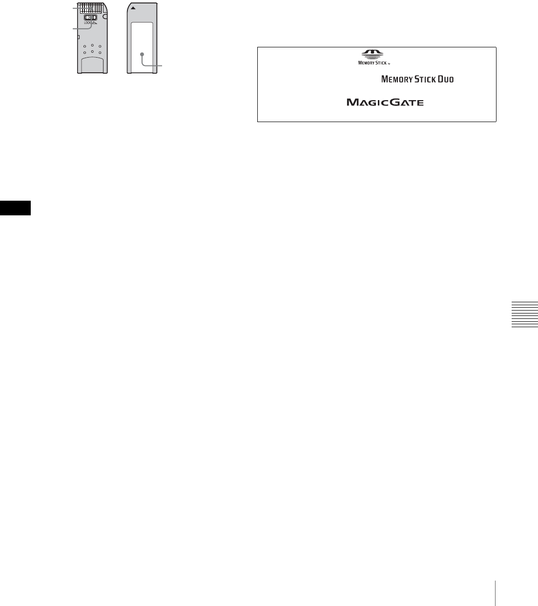
175
About a “Memory Stick”
Appendix
Note on data read/write speed
Data read/write speed may vary depending on the
combination of the “Memory Stick” and “Memory Stick”
compliant product you use.
What is MagicGate?
MagicGate is copyright protection technology that uses
encryption technology.
Before using a “Memory Stick”
• When you set the “Memory Stick” write-protect tab to
“LOCK”, data cannot be recorded, edited, or erased.
• Data may be damaged if:
- You remove the “Memory Stick” or turn off the unit
while it is reading or writing data.
- You use the “Memory Stick” in a location subject to
the effects of static electricity or electric noise.
• We recommend that you make a backup copy of
important data that you record on the “Memory Stick”.
• Do not attach anything other than the supplied label to
the “Memory Stick” labelling position.
• Attach the label so that it does not stick out beyond the
labelling position.
• Carry and store the “Memory Stick” in its case.
• Do not touch the connector of the “Memory Stick” with
anything, including your finger or metallic objects.
• Do not strike, bend, or drop the “Memory Stick”.
• Do not disassemble or modify the “Memory Stick”.
• Do not allow the “Memory Stick” to get wet.
• Do not use or store the “Memory Stick” in a location that
is:
- Extremely hot, such as in a car parked in the sun
- Under direct sunlight
- Very humid or subject to corrosive substances
“Memory Stick” access indicator
If the access indicator is turned on or is flashing, data is
being read from or written to the “Memory Stick”. At this
time, do not shake the computer or product or subject them
to shock. Do not turn off the power of the computer and
product or remove the “Memory Stick”. This may damage
the data.
Precautions
• To prevent data loss, make backups of data frequently. In
no event will Sony be liable for any loss of data.
• Unauthorized recording may be contrary to the
provisions of copyright law. When you use a “Memory
Stick” that has been pre-recorded, be sure that the
material has been recorded in accordance with copyright
and other applicable laws.
• The “Memory Stick” application software of the
camcorder may be modified or changed by Sony without
prior notice.
• Note that there are certain restrictions on recording stage
performances and other entertainment events, even if
they are recorded for personal use only.
Notes
Terminal
Write-protect tab
Labelling position
• “Memory Stick” and are trademarks of Sony
Corporation.
• “Memory Stick Duo” and “ ” are
trademarks of Sony Corporation.
• “MagicGate” and “ ” are trademarks
of Sony Corporation.
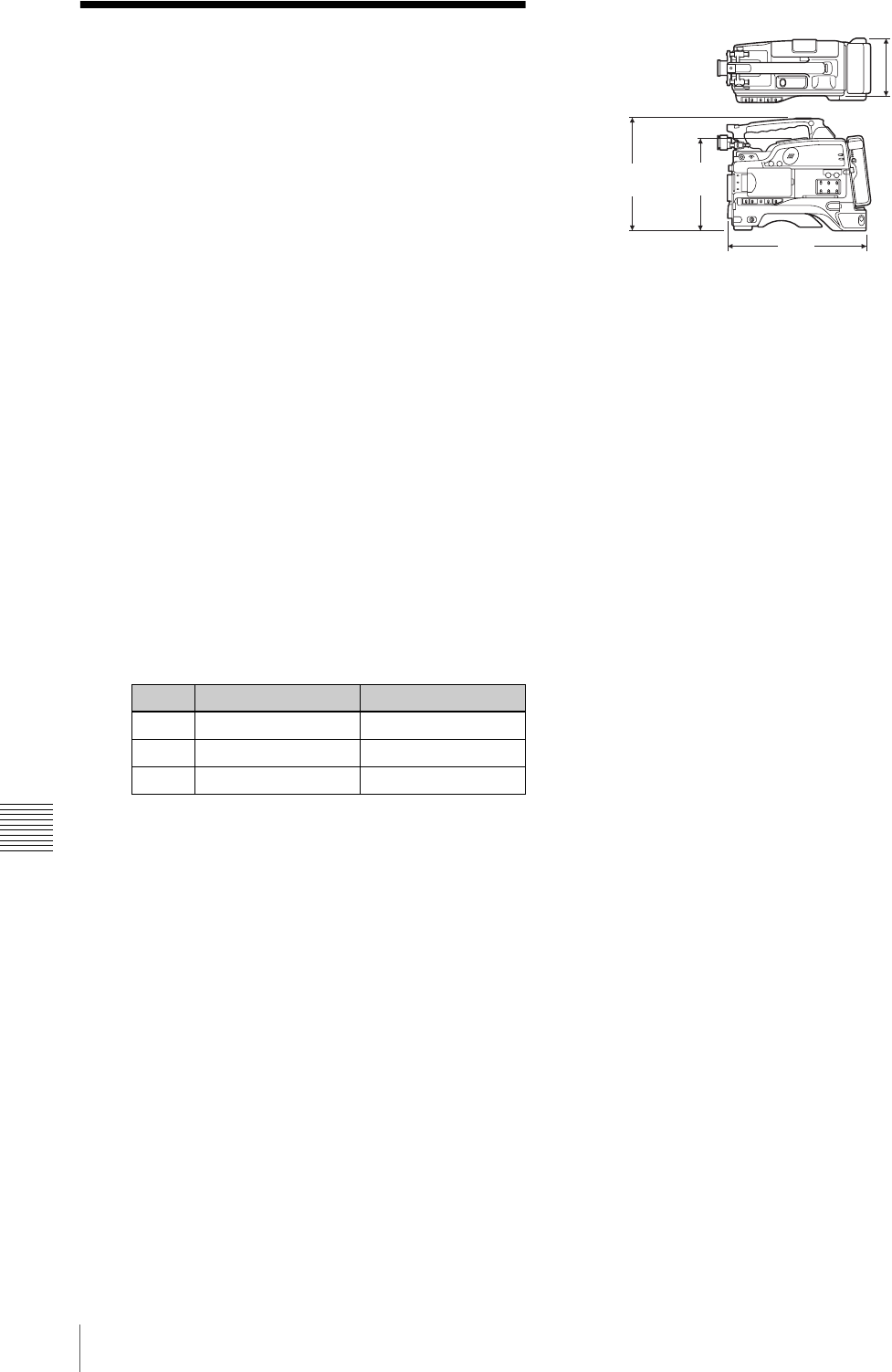
176 Specifications
Appendix
Specifications
General
Power voltage 12 V DC +5.0/–1.0 V
Power consumption
PDW-F330: 31 W
PDW-F350: 32 W
(with 12 V DC supply, when recording
with the LCD monitor on)
Operating temperature
–5°C to +40°C (23°F to 104°F)
Storage temperature
–20°C to +60°C (–4°F to +140°F)
Recording/Playback format
VIDEO MPEG HD: HQ35/SP25/
LP18 Mbps
DVCAM: 25 Mbps
Proxy video MPEG-4 1)
Audio MPEG HD: 16/24 bits, 48 kHz,
4/2 channels
DVCAM: 16 bits, 48 kHz,
4 channels
Proxy audio A-law (8 bits, 8 kHz,
4 channels)
1) The MPEG-4 CODEC is a product of Ingenient Technologies,Inc.
Recording/playback time (for PFD23)
MPEG HD
DVCAM
85 minutes
Continuous operating time
Approx. 160 min. (with BP-GL95)
Mass PDW-F330:
Approx. 3.8 kg (8 lb 6 oz) (main body
only)
Approx. 5.4 kg (11 lb 4 oz) (with DXF-
801/801CE Viewfinder, microphone,
disc and BP-GL95 Battery Pack)
Approx. 6.8 kg (14 lb 15 oz) (with DXF-
801/801CE Viewfinder, microphone,
disc, BP-GL95 Battery Pack and VCL-
719BXS Auto Focus Lens)
PDW-F350:
Approx. 3.85 kg (8 lb 7 oz) (main body
only)
Approx. 5.5 kg (12 lb 2 oz) (with DXF-
20W Viewfinder, microphone, disc
and BP-GL95 Battery Pack)
Dimensions
Supplied accessories
VCL-719BXS Auto Focus Lens (1)
(supplied with PDW-F330K only)
DXF-801/801CE Viewfinder (1) (PDW-
F330L/F330K)
DXF-20W Viewfinder (1) (PDW-F350L)
Stereo microphone (1)
Wind screen (1)
Shoulder strap (1)
VCT-U14 Tripod Adaptor (1)
Lens mount cap (1)
Flange focal length adjustment test chart
(1)
RM-F300 Infrared Remote Commander
(1)
PFD23 Professional Disc (1)
PDZ-1 Proxy Browsing Software (1)
Operating Instructions
English version (1)
Japanese version (1)
CD-ROM manual (1)
Warranty Booklet (1)
Video camera section
General
Imager 1/2-inch type, interline transfer CCD
Effective picture elements
1440 (H) & 1080 (V)
Imager Configuration
RGB 3 CCDs
Spectral system
F1.4 prism system (with quartz filter)
Built-in filter ND filter
1: CLEAR
2: 1/4 ND
3: 1/16 ND
4: 1/64 ND
Lens mount Sony 1/2-inch type bayonet-mount
Sensitivity F9 standard (89.9% reflection chart, 2000
lx)
Minimum illumination
0.13 lx (at F1.4, +48 dB gain)
Video S/N ratio 54 dB (Y-typical)
Mode 4-channel audio 2-channel audio
HQ 65 minutes or more 68 minutes or more
SP Approx. 85 minutes Approx. 90 minutes
LP 112 minutes or more 122 minutes or more
Unit: mm (inches)
124
(5)
222
(83/4)
328
(13)
268
(105/8)
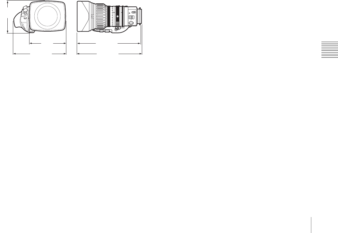
177
Specifications
Appendix
Modulation 800 TV lines
Geometric distortion
None identified (excluding distortion due
to lens)
Smear –120 dB (Y-typical)
LCD Picture: 8.9 cm (2 1/2 inches) in opposite
angle (3.5 type)
Pixel resolution: 25,000 pixels (1120
wide & 224 high)
Effective picture elements: more than
99.99%
VCL-719BXS Auto Focus Lens (supplied with the
PDW-F330K)
Focal length 6.7 mm to 127 mm
Zoom Manual or motorized, selectable
Zoom ratio &19
Maximum aperture
1:1.6, 1:2.1 (Telephoto)
Iris control Manual or automatic, selectable
F1.6 to F16 or C (closed)
Focusing Manual or automatic, selectable
Focusing range 5 cm to !
Filter attaching thread
M82 mm, 0.75-mm pitch
Mount Sony 1/2-inch bayonet mount
Mass Approx. 1.34 kg (2 lb 15 oz) (including
lens hood)
External dimensions (w/h/d)
DXF-801/801CE Viewfinder (supplied with the
PDW-F330L/F330K)
Picture tube 1.5-inch, aspect ratio 4:3, monochrome
Indicators REC (& 2), TALLY, BATT, SHUTTER,
GAIN UP
Horizontal resolution
600 TV lines
Power voltage 12 V DC
Power consumption
2.4 W
Mass Approx. 620 g (1 lb 5 oz)
Maximum dimensions
240 & 91 & 196 mm
(9 1/2 & 3 5/8 & 7 3/4 inch) (w/h/d)
DXF-20W Viewfinder (supplied with the PDW-
F350L)
Picture tube 2-inch, aspect ratio 16:9, monochrome
Indicators REC (&2), TALLY, BATT,
SHUTTER, GAIN UP
Resolution 600 lines
Power voltage 12V DC
Power consumption
3 W
Mass Approx. 620 g (1 lb 5 oz)
Maximum dimensions
239 & 76 & 215 mm (9 1/2 & 3 & 8 1/2
inches) (w/h/d)
Stereo microphone
Type Back electret condenser microphone
Directivity Super cardioid
Frequency response
100 Hz to 20 kHz
Output impedance
100 "
Power voltage 48 V DC
Mass Approx. 120 g (4 oz)
Dimensions 162 × 21 mm (6 1/2 × 27/32 inches) (length
& diameter) (excluding cable)
Optical Disc Drive Section
Video characteristics
Sampling frequency
Y: 74.25 MHz
PB/PR: 37.125 MHz
Quantization 8 bits/sample
Compression MPEG-2 MP@HL
DVCAM
Audio characteristics
Sampling frequency
48 kHz
Quantization 16-bit/2-channel, 16-bit/4-channel
Headroom 20/18/16/12 dB (selectable)
Frequency response
20 Hz to 20 kHz +0.5 dB/–1.0 dB (0 dB,
1 kHz)
Dynamic range More than 85 dB
Distortion Max. 0.08 % (1 kHz)
Input/output connectors
Signal inputs
AUDIO IN CH-1/CH-2
XLR type, 3-pin, female
–60 dBu, –50 dB, –40 dBu/+4 dBu
(0 dBu = 0.775 Vrms)
MIC IN XLR type, 5-pin, female, –50 dBu
GENLOCK IN BNC type, 1.0 Vp-p, 75 ", unbalanced
TC IN BNC type, 0.5 V to 18 Vp-p, 10 k"%(On
PDW-F330, this can be switched to
serve as TC OUT)
M
MACRO
A
PUSH
AF
FOCUS ON OFF
SERVO MANU.
ZOOM
Unit: mm (inches)
106
(41/4)
174 (67/8)
122
(47/8)211 (83/8)
215 (81/2)
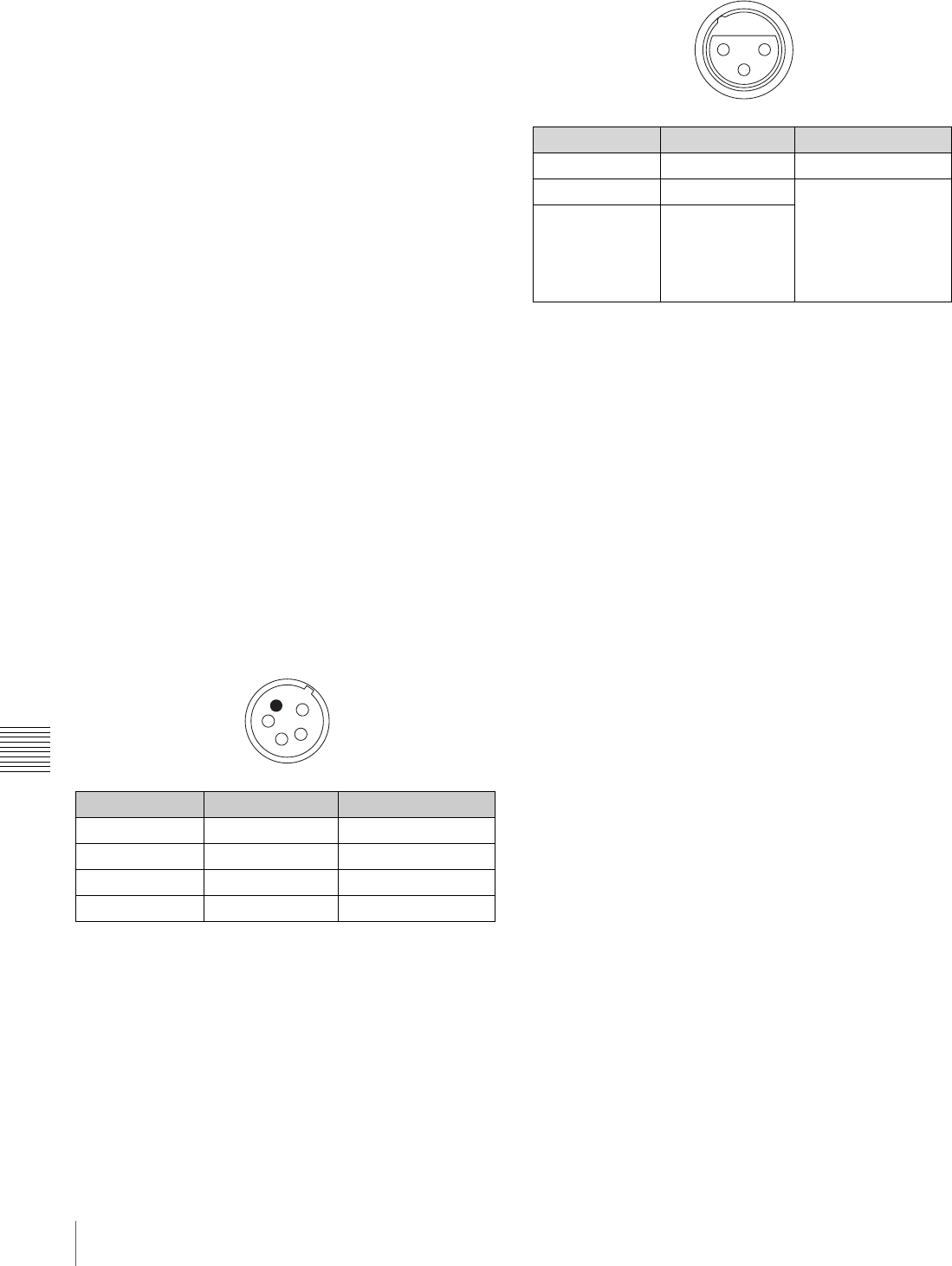
178 Specifications
Appendix
Signal outputs
AUDIO OUT CH-1/CH-2
RCA phono jack, –10 dBu, 47 k"%(PDW-
F330 only)
XLR type, 5-pin, male, +4 dBu, 600 "
(PDW-F350)
VIDEO OUT (composite)
BNC type 1.0 Vp-p, 75 ", unbalanced
VIDEO OUT (component, PDW-F330 only)
BNC type (1 set), Y: 1.0 Vp-p, 75 ",
R–Y/B–Y: 0.7 Vp-p, 75 "
HDSDI OUT (PDW-F350 only)
BNC type, SMPTE 292M
TC OUT BNC type, 1.0 Vp-p, 75 "
(On PDW-F330, this can be switched
to serve as TC IN)
EARPHONE (mini jack)
8 ", – ! to –15 dBs variable
Others
DC IN XLR type, 4-pin, male, 11 to 17 V DC
DC OUT 4-pin, 11 to 17 V DC, maximum rated
current 0.2 A
LENS 12-pin
REMOTE 8-pin
LIGHT 1) 2-pin
i.LINK 6-pin, IEEE 1394
1) The accessory fitting shoe which you can use to attach a video light to this
unit is of the 1/4-inch tapped hole type. If you want to replace this with a
slide-type shoe, contact your Sony dealer.
Pin assignment of the connectors
DC IN connector (4-pin, male)
AUDIO IN CH-1/CH-2 connector (3-pin, female)
Related products
There is a range of Sony products available to meet every
conceivable video shooting requirement.
For details, consult your Sony sales dealer.
Power supply and related equipment
BP-GL95/GL65/L60S/L80S Battery Pack
BC-L70/M150/L500 Battery Charger
AC-DN2B/DN10 AC Adaptor
Equipment for remote control
RM-B150/B750 Remote Control Unit
“Memory Stick”
MSH-32 (32 MB)
MSH-64 (64 MB)
MSH-128 (128 MB)
Audio equipment
ECM-673/674/678 Microphone
CAC-12 Microphone Holder
CA-WR855 Camera Adaptor
WRR-855 UHF Synthesized Tuner
WRR-861/862 UHF Synthesized Tuner
WRT-822/824 UHF Synthesized Transmitter
WRR Tuner Fitting (service part number: A-8278-057-B)
DMX-P01 Portable Digital Mixer
For Audio equipment described above, confirm whether
the connector is male or female and the number of pins on
the connector.
The audio input connectors of the camcorder are female
and 3-pin. A converting adaptor may be required.
Viewfinder
DXF-20W 2-inch Viewfinder (monochrome)
DXF-51/51CE 5-inch Viewfinder (monochrome)
Accessory Shoe Kit for DXF-51/51CE (service part
number: A-8274-968-B)
Pin number Signal Standard
1 EXT DC IN (G) GND
2 – –
3 – –
4 EXT DC IN (X) +11 to +17 V DC
1
23
4
Pin number Signal Standard
1 AUDIO IN (G) GND
2 AUDIO IN (X) –60 dBu, –50 dBu,
–40 dBu
When ZI is equal to
or more than 3 k"/
+4 dBu, 10 k",
balanced
3 AUDIO IN (Y)
3
2 1

179
Specifications
Appendix
Cables and miscellaneous
i.LINK cable (DV connecting cable)
CCFD-3L (6-pin y 4-pin, 3.5 m)
CCF-3L (6-pin y 6-pin, 3.5 m)
LC-H300 Hard Carrying Case
LC-DS300SFT Soft Carrying Case
LCR-1 Rain Cover
Design and specifications are subject to change without
notice.
Notes
• Always make a test recording, and verify that it
was recorded successfully.
SONY WILL NOT BE LIABLE FOR DAMAGES
OF ANY KIND INCLUDING, BUT NOT
LIMITED TO, COMPENSATION OR
REIMBURSEMENT ON ACCOUNT OF
FAILURE OF THIS UNIT OR ITS RECORDING
MEDIA, EXTERNAL STORAGE SYSTEMS OR
ANY OTHER MEDIA OR STORAGE SYSTEMS
TO RECORD CONTENT OF ANY TYPE.
• Always verify that the unit is operating properly
before use. SONY WILL NOT BE LIABLE FOR
DAMAGES OF ANY KIND INCLUDING, BUT
NOT LIMITED TO, COMPENSATION OR
REIMBURSEMENT ON ACCOUNT OF THE
LOSS OF PRESENT OR PROSPECTIVE
PROFITS DUE TO FAILURE OF THIS UNIT,
EITHER DURING THE WARRANTY PERIOD
OR AFTER EXPIRATION OF THE
WARRANTY, OR FOR ANY OTHER REASON
WHATSOEVER.
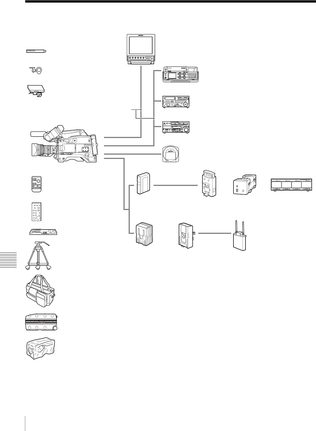
180 Chart of Optional Components and Accessories
Appendix
Chart of Optional Components and Accessories
ECM-673/674/678
Microphone
CAC-12
Microphone Holder
DXF-51/51CE a)
5-inch Viewfinder
RM-F300
Infrared Remote Commander
VCT-U14 c)
Tripod Adaptor
Tripod
LMD series
LCD Monitor
LC-DS300SFT
Soft Carrying Case
LC-H300
Carrying Case
LCR-1 Rain Cover
BP-GL95/GL65/L60S/L80S
Battery Pack
DSR-50/50P
Digital Videocassette Recorder
DSR-1500A/1500AP/1600A/1600AP/
1800A/1800AP/2000A/2000AP
Digital Videocassette Recorder
Professional disc
BC-M150
Battery
Charger
BC-L70
Battery
Charger
AC-DN2B/DN10
AC Adaptor
RM-B150/B750
Remote Control Unit
a) Optional accessory shoe kit (service part number: A-8274-968-B) is required for fitting. For details, consult your Sony dealer.
b) The cables to use for connection differ according to the application. For details, see “Connecting” (page 51).
c) Use a tripod adaptor with a suffix of “-E” or later on the model name. For more details, see “Mounting on a Tripod” (page 45).
WRR-855
UHF Synthesized Tuner Unit
CA-WR855
Camera Adaptor
PDW-F330/F350
HDW-2000 series
HD Digital Videocassette Recorder
Connection cables (not supplied) b)
BC-L500
Battery
Charger

181
Glossary
Appendix
Glossary
AES/EBU
A standard established jointly by the
AES (Audio Engineering Society)
and EBU (European Broadcasting
Union) for serial transmission of
digital audio. Two channels of audio
can be transmitted via a single
connector.
Aliasing
Distortion which occurs during
sampling to convert analog signals to
digital.
ATW
Auto Tracing White balance. The
white balance is automatically
adjusted for the lighting conditions
during shooting.
Bayonet type
A type of lens mount. The lens can be
inserted into the lens mount and fixed
in place by rotating a ring.
Black balance
To balance the black level of the R,
G, and B signals so that black has no
color.
Black set
A reference level for black balance
adjustment.
CCD
Abbreviation for charge-coupled
device. A semiconductor device used
in place of a camera pickup tube. A
semiconductor used in place of a
camera tube. The CCD converts light
into electrical charge, and outputs the
electrical charge in the form of
varying voltages.
Center marker
A cross on the viewfinder screen that
indicates the center of an image.
Clip
A recording unit. Clips are created
every time recording starts and stops.
Clip list
A list of locations in the material
recorded on the disc, arranged in any
order. Clips lists can be created with
the scene selection function of this
unit, and with the supplied PDZ-1
Proxy Browsing Software.
Color bar signals
Test signals displayed on the screen
as multicolored vertical stripes. Used
for adjustment of hue, and saturation
of a video camera and video monitor.
Color subcarrier
In a composite video signal, a signal
superimposed upon the picture
(luminance) information for the
purpose of conveying the associated
color information. Color and
saturation information is conveyed
by the phase and amplitude of the
color subcarrier. Also called
subcarrier.
Color temperature
The color quality of light, expressed
in Kelvin (K).
Reddish colors have a lower color
temperature, and blueish colors a
higher color temperature.
CRT
Cathode-Ray Tube. Video camera
viewfinders are equipped with a CRT
image display, so you can monitor
what you are shooting.
DCC
Abbreviation for dynamic contrast
control. To provide a larger dynamic
range for a video camera (the range
of brightnesses of subjects that can be
handled by the imaging device), the
knee-point is automatically adjusted
with variations in the incident light.
Drop-frame mode
SMPTE timecode runs at 30 frames/
second, while the NTSC color
television system runs at about 29.97
frames/second. Drop-frame mode
adjusts the running of timecode to
eliminate the discrepancy between
timecode value and actual time by
dropping two frames from the
timecode value at the beginning of
each minute except every tenth
minute.
EBU
Abbreviation for European
Broadcasting Union. A professional
broadcasting establishment in
Europe.
E-E mode
Electric-to-Electric mode. When you
operate a VDR in E-E mode, input
video and/or audio signals pass
through electric circuits only and
then come out from the output
connectors, without passing through
electromagnetic conversion circuits
such as recording heads.
EFP
Electronic Field Production. The use
of electronic equipment such as
portable video cameras, VTRs, and
sound equipment for television
production outside studios.
ENG
Electronic News Gathering. The use
of electronic equipment such as
portable video cameras, VTRs, and
sound equipment for the production
of daily news stories and short
documentaries.
Essence mark
A type of metadata that may be set for
a specified frame.
EXT TC (External timecode)
A timecode input from external
equipment together with audio data.
It corresponds to the conventional
timecode recorded on tape based
media. Instead the EXT TC is usually
used to record timecodes and audio
signals that are played back by
equipment that is not synchronized
with the reference video signal.
Ff
See “Flange focal length”.
Flange focal length
The distance from the plane of lens
mounting flange to the image focal
plane. Abbreviated to Ff.
Flare
Dark or colored flashes caused by
signal overload through extreme light
reflections of polished objects or very
bright lights.
Flicker
Repeated changes in screen
brightness caused by an interference

182 Glossary
Appendix
between the camera’s scanning and
the lighting conditions.
GENLOCK
A state in which devices are locked to
a signal output by a sync generator.
Genlock allows multiple devices to
operate in synchronization.
HDSDI signal
Abbreviation for High Definition
Serial Digital Interface.
This is an uncompressed digital
component video signal as specified
by SMPTE 292M.
Horizontal resolution
The horizontal resolution of the
screen, which is expressed as the
number of vertical lines
distinguishable when shooting a test
chart.
Hunting
Repeated brightening and darkening
of an image resulting from repeated
response to automatic iris control.
i.LINK
Another name for the IEEE1394-
1995 standards and their revisions.
On devices from other
manufacturers, the (i.LINK) DV
OUT S400 connector may be called a
“FireWire port”, or indicated as IEEE
1394 or DV IN/OUT. XDCAM HD
uses the i.LINK interface to transfer
DV streams by the AV/C protocol,
and toread and write MPEG IMX and
DVCAM data files by FAM (File
Access Mode).
Interlaced scan mode
A scanning method in which odd
rows fields are read alternately with
even rows. (Odd-row fields and even-
row fields contain images from
different times.)
IRE scale
International Radio Engineers scale.
A scale of values that defines the
brightness level of a video signal.
The IRE is now the IEEE (Institute of
Electrical and Electronic Engineers).
Metadata
Information about the properties of
video and audio content. XDCAM
records metadata such as UMIDs and
essence marks, and the supplied
PDZ-1 Proxy Browsing Software can
be used to record information such as
titles and comments.
MXF
Material eXchange Format. A file
exchange format developed by the
Pro-MPEG Forum. Equipment from
different manufacturers can
exchange files in this format.
ND filter
ND is an abbreviation of Neutral
Density. An optical filter that reduces
the incident light uniformly across
the whole wavelength range, without
affecting the color rendering of the
subject.
Non-drop-frame mode
A mode of advancing timecode
which ignores the difference in frame
values between real time and the
timecode. Using this mode produces
a difference of approximately 86
seconds per day between real time
and timecode, which causes
problems when editing programs in
units of seconds using the number of
frames as a reference.
Non-audio
General term for audio signals other
than linear PCM, such as Dolby E
and Dolby Digital (AC-3). 1)
XDCAM can record non-audio as an
input signal.
1) Dolby is a trademark of Dolby Laboratories.
NTSC
Abbreviation for National Television
System Committee. NTSC is a color
TV broadcasting system adopted
mainly in North American countries,
and in parts of Asia and Central and
South America.
PAL
Abbreviation for Phase Alternating
Line. PAL is a color TV broadcasting
system developed by Telefunken
GmbH of Germany. This system is
adopted mainly in European
countries, in Australia, and in parts of
Asia and South America.
Progressive scan mode
A scanning method in which odd
rows and even rows are read at the
same time. Also called full-screen
scanning.
Proxy AV data
Low-resolution data with a video
bandwidth of 1.5 Mbps and an audio
bandwidth of 64 kbps per channel.
This unit records proxy AV data
automatically whenever high-
resolution MPEG HD or DVCAM
data is recorded.
Reference video signal
A video signal that contains a sync
signal or sync and burst signals, used
as a reference for synchronization of
video equipment.
Return video
Video signals that are sent back from
a VTR to a camera or from a control
console to a camera so that a camera
operator can verify the recorded/
selected video signals.
Sampling frequency
A method used to sample an analog
signal so that it can be represented
digitally. The higher the sampling
frequency is, the more accurately the
high-frequency analog signal can be
represented.
SDSDI signal
Standard Definition Serial Digital
Interface. An interface standardized
as SMPTE 259M which enables the
transmission of an uncompressed
digital component stream.
Shot data
Data recorded, while shooting, in the
color bars, the user bits data of VITC,
and so forth. Includes the model
name, serial number, date, time, shot
number, and ID1 to ID4.
Shutter speed
The time that the shutter is open.
Slow shutter speeds give bright
images, but motion resolution is
lower.
SMPTE
Society of Motion Picture and
Television Engineers, a professional
association established in the U.S.A.
mainly for the purpose of setting
forth motion picture and television
engineering standards.

183
Glossary
Appendix
S/N
Signal-to-Noise ratio. The relation of
the strength of the desired signal to
the accompanying electronic
interference, the noise. If S/N is high,
sounds are reproduced with less noise
and pictures are reproduced clearly
without snow.
Sub clip
One of the sections which make up a
clip list. A sub clip may be part of a
clip or an entire clip.
Superimpose
A procedure you use to put one
picture (or character) over another so
that both can be seen at the same
time.
Thumbnail image
A reduced still picture of video for
display on a GUI screen. XDCAM
creates thumbnail images from proxy
video, and displays them as index
pictures on GUI screens.
Timecode
A digitally encoded signal which is
recorded with video data to identify
each frame of the video by hour,
minute, second and frame number.
SMPTE timecode is applied to NTSC
system, and EBU timecode to PAL
and SECAM systems.
Timecode synchronization
To synchronize the built-in timecode
generator of video equipment to an
external timecode.
Time data
Time information that is generated by
a timecode generator or read by a
timecode reader.
Turbo gain
Video amplifier gain increased from
30 dB by 6 to 18 dB by combining
adjacent pixels of the CCD.
UMID
Unique Material Identifier. A
standard (SMPTE 330M) for video
and audio metadata. The Basic
section of a UMID contains a
globally unique number and a
material number for the identification
of recorded material. An optional
section called the Source Pack
contains information such as the time
and location of recording. A UMID
with the Basic section only is called a
Basic UMID. A UMID with the
Source Pack is called an Extended
UMID.
User’s bits
Abbreviation for Total Level Control
System. A function to operate the
automatic gain control (AGC) and
electronic shutter (AE) to adapt to
varying lighting conditions while
shooting.
VBS
Abbreviation for video-burst-sync. A
composite signal consisting of a
video signal, a burst signal, and a
sync signal.
Vertical smear
A bright vertical line which appears
on the screen when shooting a very
bright object with a CCD camera.
Also called smear.
Video gain
Amount of amplification for video
signals, expressed in decibels (dB).
VITC
Abbreviation for vertical interval
timecode. A timecode recorded on
disc with video signals and inserted
in the vertical blanking interval of
video signals. The VTR can read this
timecode even in still mode.
White balance
The balance of the levels of the red,
green, and blue channels of a color
video camera level. When this
balance is correctly adjusted, white
tones appear as a true white.
White shading
When shooting a white subject with a
color video camera, if the lens
characteristics are such that while the
center of the image appears white, the
upper and lower portions suffer a
color imbalance, appearing magenta
or green. This phenomenon is called
white shading.
Zebra pattern
Striped patterns that appear in the
viewfinder to indicate areas of the
picture where the video level is about
70 IRE units or 490 mV.
Zoom
To gradually change the field of view
of a camera lens from wide to narrow
angle (zoom in) or narrow to wide
angle (zoom out).

184 Index
Index
Index
Numerics
23.98P mode 144
5600 indicator 32
5600K button 15
5-inch electronic viewfinder, attaching
43
A
About data transfer speed of i.LINK
173
AC adaptor 36
ACCESS indicator 19
Accessory fitting shoe 23
ALARM knob 16
Alarm messages 166
Area of use
setting 37
Aspect Ratio, selecting 143
ASSIGN 1/2 switches 14
ASSIGN 3/4 switches 22
ASSIGNABLE page 112
Assigning functions to ASSIGN
switches 142
ATW 16, 62
Audio channel
display 18
selecting 20
AUDIO IN CH-1/CH-2 connectors 25
AUDIO IN input selection switches
25
AUDIO IN switches 21
Audio input
external microphone 46
supplied microphone 46
Audio input signal selection 21
Audio level
adjusting 65
indicator 18, 32
Audio level adjustment method
selection 21
AUDIO LEVEL knob (front) 14
AUDIO LEVEL knobs 21
AUDIO LEVEL knobs (side) 21
AUDIO OUT CH-1/CH-2 connectors
26
AUDIO OUT connector 26
AUDIO SELECT switches 21
AUDIO-1 page 122, 123
AUDIO-2 page 123
Auto focus button 27, 33
Auto focus indicator 27
Auto focus lens 27
Auto focus ranging sensor 13
AUTO W/B BAL switch 13
Automatic iris, setting 64
B
BATT indicator 30
Battery attachment shoe 24
Battery capacity indicator 18
Battery pack
attaching 36
detaching 36
operation time 36
Black balance
automatic adjustment 13, 59
BRIGHT button 17
BRIGHT control 30
Built-in speaker 19
C
CAM CONFIG page 124
Camera person TALLY indicator 30
Camera scan mode indicator 18
Change confirmation/adjustment
progress messages 137
Chapter function 85
adding sub clips 96
Clip 92
assigning titles automatically 75
Assigning User-Defined Clip
names 77
deleting 69, 88
Locking 87
recording 58
Clip list 92
creating 93
deleting from the disc 101
managing 100
name display 31
playback 86
Sorting 101
CLIP TITLE page 113
CLK 19
CNT 19
Color bar signal, outputting 16
Color temperature, setting 141
Component video signal output
connector 23
Composite video signal output
connector 24, 26
Connecting
controlling from a non-linear
editing system 52
controlling from the VTR using
the editing function 52
copying digitally 52
external video monitor 51
i.LINK connection settings 52
Connector section 23
CONTRAST control 30
COUNTER/CHAPTER button 17
Current clip list 92
reading from the disc 101
D
Date/time
setting 39
DC IN / battery voltage or remaining
capacity 31
DC IN connector 25
DC OUT 12 V connector 26
DCC (Dynamic Contrast Control) 16
DETAIL page 119
DF/NDF 66
DIAGNOSIS menu 129
Directory Structure 155
Disc
ejecting 20
handling 54
loading and unloading 55
remaining capacity indicator 18,
32
write-protecting 54
DISC page 112
Display items, selecting 136
DISPLAY switch 30
DISPLAY/EXPAND button 16
DV OUT connector 25
DXF-20W 29
DXF-801/801CE 29
E
EARPHONE jack 19
ECS 62
E-E 19
EJECT button 19, 20
Electronic shutter 62
ESSENCE MARK page 123
Essence Marks
recording 70
Expand function 85
adding sub clips 95
External synchronization indicator 18
Eyepiece focusing knob 30
Eyepiece focusing ring 30
Eyepiece release catch 30
EZ focus 57, 143
EZ mode 57, 143
EZ MODE/TLCS page 113
F
F FWD button 20, 33
F REV button 20, 33

185
Index
Index
FAM connections 158
Features 9
File access mode (FAM) 158
FILE menu 127
File operation 155
restrictions 156
Filter indicator 32
FILTER selector 13
Fitting for optional microphone holder
23
Flange focal length adjustment button
27
Flange focal length, adjusting 40
using a non-auto focus lens 41
using the VCL-719BXS auto
focus lens 40
Flicker 59
Focus control connector 28
Focus indicator 31
Focus ring 27
FOCUS switch 27
FORMAT page 111
Four-way arrow key 21, 33
Frame frequency
indicator 31
setting 37
FRONT MIC LOW CUT switch 22
F-RUN/SET/R-RUN switch 22
G
Gain
setting values for the GAIN
selector positions 140
value 32
GAIN SW page 113
GAIN switch 15
GAIN UP indicator 30
Gamma Tables 142
GENLOCK IN connector 23
Glossary 181
H
“Memory Stick”
handling 146
HDSDI OUT connector 26
Hold indicator 18
I
i.LINK
data transfer speed 173
overview 173
settings required for connection
52
i.LINK connector 25
IEEE1394 connector 25
IG control 28
Infrared remote commander 32
using 33
Internal timecode generator
selecting operating mode 22
Interval recording 71
settings before shooting 71
shooting 72
IRIS button 28
Iris gain control 28
Iris ring 27
Iris setting/auto iris override indicator
32
IRIS switch 28
Iris, adjusting 64
K
KNEE page 119
L
Large viewfinder attachment shoe 22
LCD monitor 16
operating buttons 16
status display 17, 136
LCD page 116
Lens 27
mounting 40
LENS connector 13
Lens file, selecting 143
Lens locking lever 14
Lens mount 13
Lens mount cap 13
Lens mount securing rubber 13
LIGHT connector 23
LIGHT switch 15, 30
Line input audio equipment,
connecting 49
Lithium battery
attaching and replacing 35
replacing 33
service life 35
warning indicator 18
Lithium battery compartment 21
Live & Play Function 79
Lock ring 30
LOW KEY SAT page 120
M
MACRO switch 27
Maintenance
cleaning the viewfinder 164
MAINTENANCE menu 122
Marker display, setting 137
MARKER page 115
MATRIX 2 page 120
MATRIX page 120
“Memory Stick”
handling 146
inserting 146
overview 174
protecting saved data 147
removing 146
types 174
“Memory Stick” slot 25, 146
Menu
adjustments and settings 140
basic operations 131
DIAGNOSIS menu 129
displaying 131
ending 131
FILE menu 127
MAINTENANCE menu 122
OPERATION menu 111
organization 103
PAINT menu 118
TOP menu 110
USER menu 132
MENU knob 14
Menu list 111
MENU switch 16
MIC IN connector 23
Microphone, attaching 46
MONITOR knob 15
MONITOR OUT CHARACTER
switch 22
MONITOR switches 20
MPEG-4 License 173
N
ND filter, selecting 13
NEXT button 20, 33
Non drop-frame mode indicator 18
O
OFFSET WHITE page 114
OPERATION menu 111
Operation warnings 165
Operation/alarm message display area
32
Operation/alarm messages 166
Optional components and accessories
180
OUTPUT page 114
Output signals, selecting 140
OUTPUT/DCC switch 16
Overview 8
P
PAINT menu 118
PAINT page 118
PDZ-1 102
PEAKING control 30
Picture Cache Function 74

186 Index
Index
PLAY/PAUSE button 20, 33
Playback 80
clip list 86
indicator 18
Viewing Camera Video 79
Power supply
preparing 36
POWER switch 15
Power zoom lever 28
Pre-lighting function 71
PRESET/REGEN/CLOCK switch 22
PREV button 20, 33
Product configurations 8
PUSH AF button 27, 33
PUSH SET button 33
R
REC button 13, 28, 33
REC PAUSE button 33
REC/TALLY indicators 30
Recording
advanced operation 71
basic operation 58
checking on a color video monitor
81
review 81
shot data superimposed on the
color bars 138
Starting a Shoot With a Few
Seconds 74
Recording format
indicator 18, 31
selecting 58
Recording level adjustment 21
Remaining disc capacity indicator 18
Remote commander receptor 14
REMOTE connector 26
Remote control unit
camcorder switch functions when
connected 49
connecting 49
paint adjustment when connected
49
structure of the paint adjustment
data 50
RESET button 17
RESET page 117
RET button 28
RM-F300 32
S
S400 connector 25
Scan mode 144
indicator 18
Scene file
loading 152
saving 150
setting the file ID 152
SCENE FILE page 121
Scene selection
creating clip list 93
editing sub clips 97
flow of editing 91
managing clip lists 100
overview 90
Searching
chapter function 85
expand function 85
thumbnail 82
SEL/SET button 21
Setting change and adjustment
progress message display area 32
SHIFT button 21
Shooting 57
SHOT DISP page 116
SHOT ID page 116
Shot ID, setting 139
SHOT MARK 70
SHOT MARK 1/2 buttons 33
Shoulder pad 23
adjusting the position 44
Shoulder strap
fitting 44
removing 44
Shoulder strap fitting 23
SHUTTER indicator 30
Shutter mode 62
Shutter speed 62
indicator 32
SHUTTER switch 14
Side control panel 20
protection cover 19
SKIN DETAIL page 119
Skin detail, correcting 69
Slow & Quick-motion shooting 73
SLS 62, 63
SPECIAL EFFECTS page 112
Specifications
general 176
optical disc drive section 177
pin assignment of the connectors
178
related products 178
stereo microphone 177
supplied accessories 176
video camera section 176
Starting a Shoot With a Few Seconds
74
Status display 140
STOP button 20, 33
Stopper 30
SUB CLIP button 33
SUB CLIP indicator 21
Sub clips 92
editing 97
Superimposed text
adding 22
SW STATUS page 118
T
TALLY light 24, 30
Tally light 30
TALLY switch 24
TALLY switch (viewfinder) 30
TC connector 26
TC IN connector 24
TC OUT connector 24
TCG 19
TCR 19
Testing
camera 162
preparating 162
VDR 163
THUMBNAIL button 21, 33
Thumbnail image
Changing index frame 83
Setting at recording time 70
Switching the information 83, 99
THUMBNAIL indicator 21
Thumbnail search 82
TIME / DATE page 116
Time counter display 19
Timecode
indicator 31
making the time code consecutive
67
saving the actual time 67
setting 66
TIMECODE page 123
TLCS 113, 143
TOP menu 110
Tripod
mounting 45
removing 45
Troubleshooting 169
U
UBG 19
UBR 19
UHF synthesizer tuner, attaching
WRR-855 47
WRR-861/862 48
UMID Data 171
UMID SET page 117
User bits, setting 67
User file
loading 149
saving 147
setting the file ID 148
USER menu

187
Index
Index
editing 133
moving to another page 133
resetting 135
setting 132
USER MENU CUSTOMIZE menu
adding a new page 133
adding/deleting/replacing pages
135
V
VCL-719BXS 27
VDR operation indicators 31
VDR SAVE/STBY switch 15
VF connector 13
VF DISP 1 page 115
VF DISP 2 page 116
VF SETTING page 115
Video camera section 176
Video light, attaching 45
VIDEO OUT CHARACTER switch
22
VIDEO OUT connector 24, 26
VIDEO OUT page 115
VIDEO OUT Y/PB/PR connector 23
Video signal from the camera,
outputting 16
Viewfinder 29
adjusting contrast and brightness
43
adjusting the eyepiece focus 43
adjusting the outline emphasis 43
adjusting the position 42
attaching 42
cleaning 164
detaching 42
setting 138
status display 136
status display on the screen 31,
136
Viewfinder connector 30
Viewfinder fitting shoe 23
Viewfinder front-to-back positioning
knob 22
Viewfinder left-to-right positioning
ring 23
Volume adjustment 15
W
WARNING indicator 19
Warning indicator area 18
WHITE BAL switch 16
White balance
adjusting 60
ATW 62
automatic adjustment 13
memory indicator 32
offset 141
WHITE page 118
WHITE SETTING page 124
WRR connector 24
Z
ZEBRA button 14
Zoom control connector 28
Zoom position indicator 31
Zoom ring 27
ZOOM switch 28
ZOOM T/W buttons 33

Sony Corporation
