Sony Dmx R100 Users Manual
DMX-R100 to the manual 5669a7bf-789a-4f89-89dd-e7f755fdca1c
2015-01-23
: Sony Sony-Dmx-R100-Users-Manual-297449 sony-dmx-r100-users-manual-297449 sony pdf
Open the PDF directly: View PDF ![]() .
.
Page Count: 1
- Table of Contents
- Chaper 1
- Chapter 2
- Locations and Functions of Parts and Controls
- Composition of the Front Panel
- Analog Head Amplifier Panel
- Channel Meter Panel
- Channel Strip Panel
- Talk-Back Panel
- Assignment Panel
- Parameter Setting Panel
- Master Panel
- Automation Panel
- Elements of the Rear Panel
- Power Supply Section
- Control Signal Connectors
- Analog Signal Connectors
- Digital Signal Connectors
- Optional Boards
- Locations and Functions of Parts and Controls
- Chapter 3
- Menu Structure
- Basic Components and Functions of the Windows
- Menu Windows
- CHANNEL Window
- INPUT/PAN/ASSIGN Window
- EQUALIZER/FILTER Window
- DYNAMICS Window
- AUX SEND Window
- AUDIO OVERVIEW Window
- AUDIO FADER Window
- AUDIO FADER GROUPING Window
- AUDIO INPUT ROUTING Window
- AUDIO OUTPUT ROUTING Window
- MONITOR Window
- OSC/TALKBACK Window
- SNAPSHOT Window
- CUE Window
- AUTOMATION Window
- MACHINE CONTROL Window
- TITLE MANAGER Window
- MIDI Window
- SYNC/TIME CODE Window
- I/O STATUS Window
- MISC SETUP Window
- KEYBOARD Window
- Chaper 4
- Appendix

1999 Sony Corporation
Operating Instructions
Before operating the unit, please read this manual
thoroughly and retain it for future reference.
3-868-264-12 (1)
Digital Audio Mixer
DMX-R100
2
Owner’s Record
The model and serial numbers are located on the rear.
Record the serial numbers in the spaces provided below.
Refer to them whenever you call upon your Sony dealer
regarding the product.
Model No. DMX-R100 Serial No.______________
WARNING
To prevent fire or shock hazard, do not expose the unit to
rain or moisture.
To avoid electrical shock, do not open the cabinet. Refer
servicing to qualified personnel only.
THIS APPARATUS MUST BE EARTHED.
This symbol is intended to alert the user to
the presence of important operating and
maintenance (servicing) instructions in the
literature accompanying the appliance.
This symbol is intended to alert the user to
the presence of uninsulated "dangerous
voltage" within the product's enclosure that
may be of sufficient magnitude to
constitute a risk of electric shock to
persons.
For the customers in the U.S.A.
This equipment has been tested and found to comply with
the limits for a Class A digital device, pursuant to Part 15 of
the FCC Rules. These limits are designed to provide
reasonable protection against harmful interference when the
equipment is operated in a commercial environment. This
equipment generates, uses, and can radiate radio frequency
energy and, if not installed and used in accordance with the
instruction manual, may cause harmful interference to radio
communications. Operation of this equipment in a residential
area is likely to cause harmful interference in which case the
user will be required to correct the interference at his own
expense.
For the customers in Europe
This product with the CE marking complies with both the
EMC Directive (89/336/EEC) and the Low Voltage Directive
(73/23/EEC) issued by the Commission of the European
Community.
Compliance with these directives implies conformity to the
following European standards:
• EN60065: Product Safety
• EN55103-1: Electromagnetic Interference (Emission)
• EN55103-2: Electromagnetic Susceptibility (Immunity)
This product is intended for use in the following
Electromagnetic Environment(s):
E1 (residential), E2 (commercial and light industrial), E3
(urban outdoors) and E4 (controlled EMC environment, ex.
TV studio).
Pour les clients européens
Ce produit portant la marque CE est conforme à la fois à la
Directive sur la compatibilité électromagnétique (EMC) (89/
336/CEE) et à la Directive sur les basses tensions (73/23/
CEE) émises par la Commission de la Communauté
européenne.
La conformité à ces directives implique la conformité aux
normes européennes suivantes:
• EN60065: Sécurité des produits
• EN55103-1: Interférences électromagnétiques (émission)
• EN55103-2: Sensibilité électromagnétique (immunité)
Ce produit est prévu pour être utilisé dans les
environnements électromagnétiques suivants:
E1 (résidentiel), E2 (commercial et industrie légère), E3
(urbain extérieur) et E4 (environnement EMC contrôlé ex.
studio de télévision).
Für Kunden in Europa
Dieses Produkt besitzt die CE-Kennzeichnung und erfüllt
sowohl die EMV-Direktive (89/336/EEC) als auch die
Direktive Niederspannung (73/23/EEC) der EG-Kommission.
Die Erfüllung dieser Direktiven bedeutet Konformität für die
folgenden Europäischen Normen:
• EN60065: Produktsicherheit
• EN55103-1: Elektromagnetische Interferenz (Emission)
• EN55103-2: Elektromagnetische Empfindlichkeit
(Immunität)
Dieses Produkt ist für den Einsatz unter folgenden
elektromagnetischen Bedingungen ausgelegt:
E1 (Wohnbereich), E2 (kommerzieller und in beschränktem
Maße industrieller Bereich), E3 (Stadtbereich im Freien) und
E4 (kontrollierter EMV-Bereich, z.B. Fernsehstudio)
You are cautioned that any changes or modifications not
expressly approved in this manual could void your authority
to operate this equipment.
The shielded interface cable recommended in this manual
must be used with this equipment in order to comply with the
limits for a digital device pursuant to Subpart B of Part 15 of
FCC Rules

Table of Contents 3
(Continued)
Table of Contents
Chaper 1
Overview Overview ............................................................................ 6
Connection Examples....................................................... 7
Video Post Production...................................................... 7
Music Production ............................................................. 8
Live Recording ................................................................. 9
Chapter 2
Locations and Functions
of Parts and Controls
Locations and Functions of Parts and Controls .......... 10
Composition of the Front Panel ..................................... 10
Analog Head Amplifier Panel ........................................ 11
Channel Meter Panel ...................................................... 11
Channel Strip Panel ........................................................ 12
Talk-Back Panel ............................................................. 14
Assignment Panel ........................................................... 16
Parameter Setting Panel ................................................. 17
Master Panel ................................................................... 22
Automation Panel ........................................................... 25
Elements of the Rear Panel ............................................ 28
Power Supply Section .................................................... 28
Control Signal Connectors ............................................. 29
Analog Signal Connectors.............................................. 31
Digital Signal Connectors .............................................. 33
Optional Boards ............................................................. 34
Chapter 3
Menu Menu Structure ................................................................ 36
Basic Components and Functions of the Windows .... 37
Basic Components of the Windows ............................... 37
Operating the Touch Panel ............................................. 41
Menu Windows ................................................................ 43
CHANNEL Window ...................................................... 43
INPUT/PAN/ASSIGN Window..................................... 44

4Table of Contents
Table of Contents
Chapter 3
Menu EQUALIZER/FILTER Window .................................... 46
DYNAMICS Window.................................................... 47
AUX SEND Window ..................................................... 49
AUDIO OVERVIEW Window ...................................... 50
AUDIO FADER Window .............................................. 51
AUDIO FADER GROUPING Window ........................ 52
AUDIO INPUT ROUTING Window ............................ 55
AUDIO OUTPUT ROUTING Window ........................ 57
MONITOR Window ...................................................... 59
OSC/TALKBACK Window .......................................... 62
SNAPSHOT Window .................................................... 64
CUE Window ................................................................. 66
AUTOMATION Window .............................................. 68
MACHINE CONTROL Window .................................. 70
TITLE MANAGER Window......................................... 72
MIDI Window ................................................................ 75
SYNC/TIME CODE Window........................................ 76
I/O STATUS Window.................................................... 81
MISC SETUP Window .................................................. 84
KEYBOARD Window ................................................... 86
Chaper 4
Operation Tips For System Setup............................................................ 87
Changing the Keyboard Type ........................................ 87
Updating the DMX-R100 System .................................. 87
Memory Structure and Title............................................ 88
Structure of Snapshot and Automation Memory ........... 88
About Titles.................................................................... 89
Basic Operation Procedure ............................................ 91
Basic Mixer Operation Flow from Turning On to
Monitoring ................................................................ 91
Snapshot Automation Procedure .................................... 94
Cue Operation Procedure ............................................... 96
Automation Procedure ................................................... 98

Table of Contents 5
Using the Automatic Isolate Function.......................... 103
Using the Write Hold Mode ......................................... 103
Punching In/Punching Out ........................................... 104
Dialogues on the Window ............................................ 107
Appendix
Specifications ................................................................ 110
Input/Output Connectors .............................................. 110
Audio Characteristics ................................................... 112
Automation Function ................................................... 113
Others ........................................................................... 114
Supplied Accessories ................................................... 114
Optional Accessories.................................................... 114
MIDI ................................................................................. 115
MIDI Implementation Chart ........................................ 115
Control Change Table .................................................. 116
Index ............................................................................... 118
Block Diagram ...............................................................121

6
Chaper 1 Overview
Chaper 1 Overview
Overview
The DMX-R100 is a compact digital audio mixer for a
post production house that creates digital media or
digital broadcasting.
High quality audio signal processing
The unit allows you to select the sampling frequency
to 44.1 kHz, 48 kHz, 88.2 kHz or 96 kHz.
When you select either 88.2 kHz or 96 kHz, the
frequency response range expands to 40 kHz.
The analog signal is converted to a 24-bit digital signal
in the mixer. The unit enables AES/EBU format input/
output with at least 24-bit precision. The high
precision floating point used for internal calculation
results in high quality signal processing.
When either 88.2 kHz or 96 kHz is selected as a sampling
frequency, the number of channels and optional boards is
limited.
For details, see page 76.
Easy operation using the high resolution
color LCD and touch panels
The parameters of each channel are displayed in color
and as patterns on one screen. This improves the
operation for equalization or dynamics setting and
allows you to perform operations precisely and
quickly.
Snapshot/Automation functions for
professional use
• Snapshot
The unit can memorize up to 99 control settings
(snapshots) such as settings of faders and controls on
the channel strips, settings of the equalizer or
dynamics for source signals, signal path, etc., as
snapshot data. You can easily recall the snapshot
data, allowing you to preset programs
instantaneously.
• Automation
You can select either SMPTE or MTC (MIDI
timecode) as the timecode for reference.
The unit can memorize and recall parameters such as
faders, pan controls, equalizer, dynamics and AUX
signal setting. Also the fader is touch sensitive to
improve operation. A scene stored as a snapshot data
can be linked with a cue point with a defined
timecode value. These functions provide you with the
same function as those of a large console-type mixer.
• You can store snapshot automation data and dynamic
automation data on a 3.5-inch floppy disk.
The channel strips
The LEDs of the pan controls and faders on the
channel strip allow you to see the analog data at a
glance. You can define the desired parameters to pan
pots and faders, directly confirming analog data on the
channel strips.
Flexible built-in matrix switchers
• The built-in input matrix switcher allows you to
assign standard analog input, digital input or input
from option boards to any desired channel. You can
change the switcher operation easily using the touch
panel on the screen.
• The built-in output matrix switcher allows you to
assign the outputs of PGM buses, AUX buses and
MTR buses to the output of the desired optional
boards. Also, the unit can output one signal to
different output connectors at the same time.
Large number of channels
• The unit is equipped with 24 analog channels which
can input a wide variety of analog sources. Also, the
unit is equipped with XLR connectors and standard
TRS jacks.
• In addition to 48 fully featured input channels, the
unit has 8 AUX returns. This allows you to mix up to
56 channels at the same time. Also, the PGM bus,
AUX bus and MTR bus are equipped with equalizer
and dynamics control.
• The unit has four optional slots. The optional board
handles 8 inputs and/or outputs. Thus, maximum 32
channels of inputs/outputs are available from the four
slots.
Surround mode
• 5.1 surround mode can be set using the MTR bus.
• The unit has 6 channels for surround monitors, so it is
not necessary to use other outputs for monitoring.
• You can control the surround pan with touch panel
operation.
Stored sound images can be recalled using dynamic
automation.
Connection to video equipment
• The unit can synchronize with video equipment such
as a digital VTR, by supplying reference video
signals. Since the unit is equipped with video input
connectors, it is not necessary to use an external
connector.
• The unit can control external devices conforming to
the Sony 9-pin remote serial interface, by connecting
external devices such as a VTR to the remote
connector on the rear panel.
Chapter 1 Overview
7
Chaper 1 Overview
Chaper 1 Overview
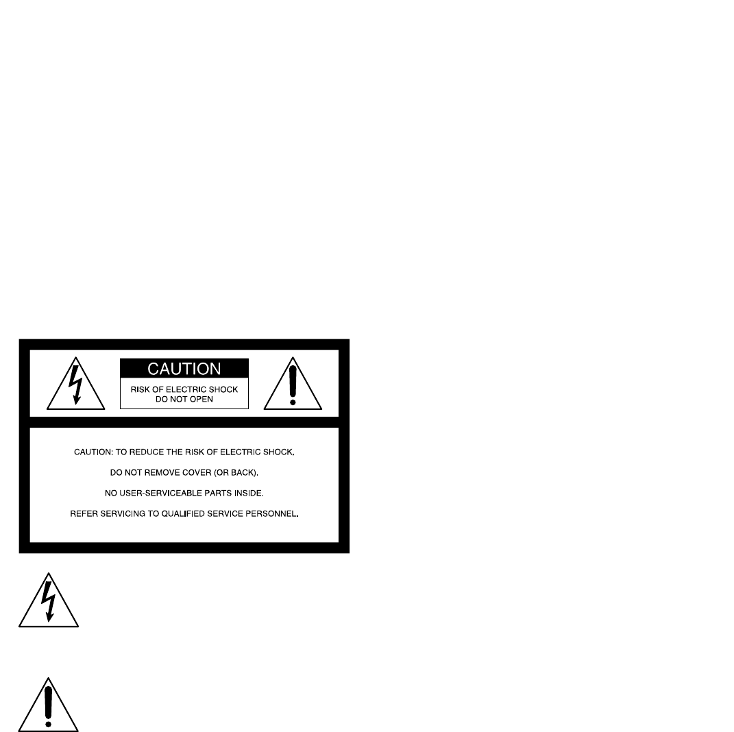
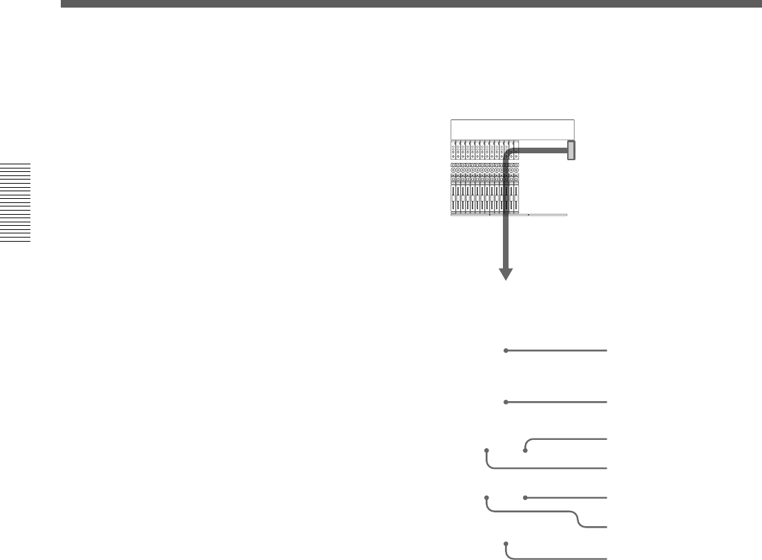
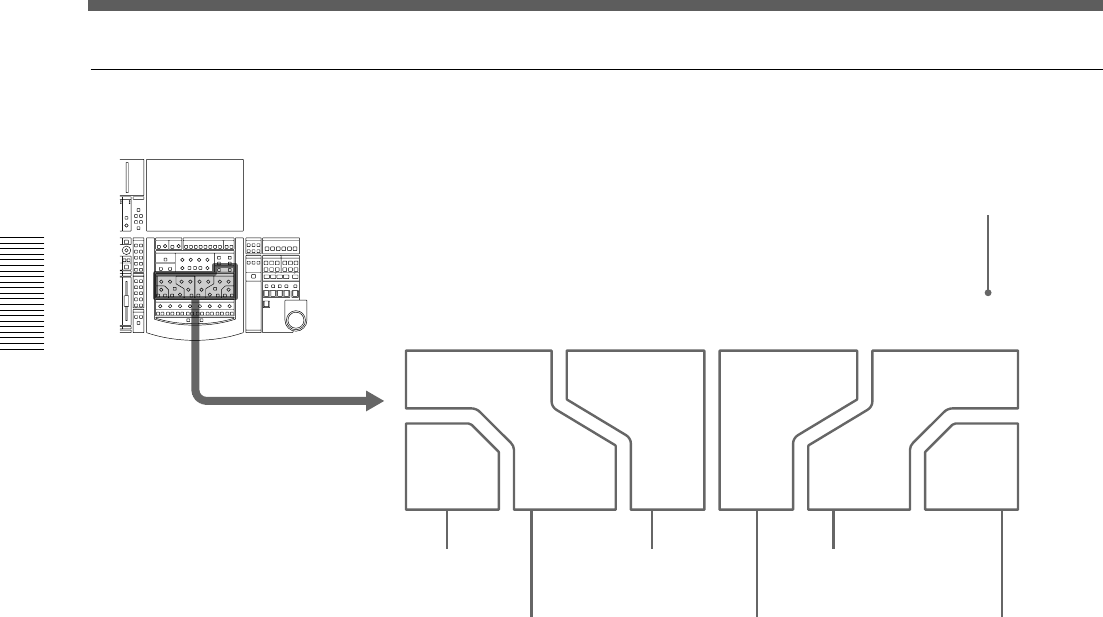
Connection Examples
Video Post Production
Effect processors (analog)
to INSERTION
(INPUT/OUTPUT)
Surround monitors Microphones
to TIME CODE from REMOTE to 2TRIN 2
from PGM
from CR MONITOR to IN A
to REF VIDEO
to AUX RET
from AUX
SEND
to the slot
(DMBK-R107) to the slot
(DMBK-R103)
Video reference signal generator
Digital reverb
Effect processor
(digital)
TASCAM DAT VTR
For the signal flow, see “Block
Diagram” on page 121.
from REF
VIDEO
from REF
WORD OUT
VTR
Chapter 1 Overview
8
Chaper 1 Overview
Chaper 1 Overview
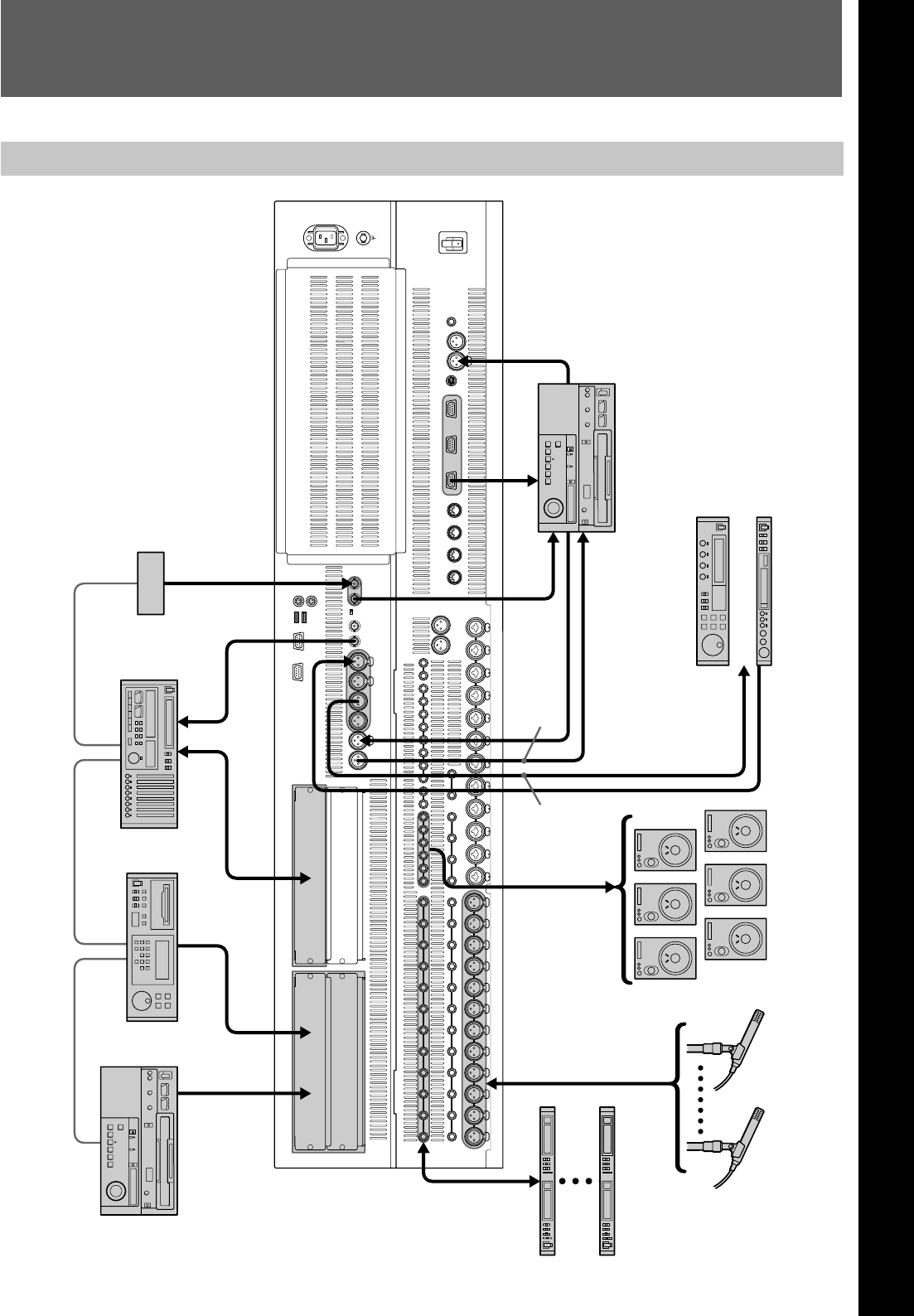
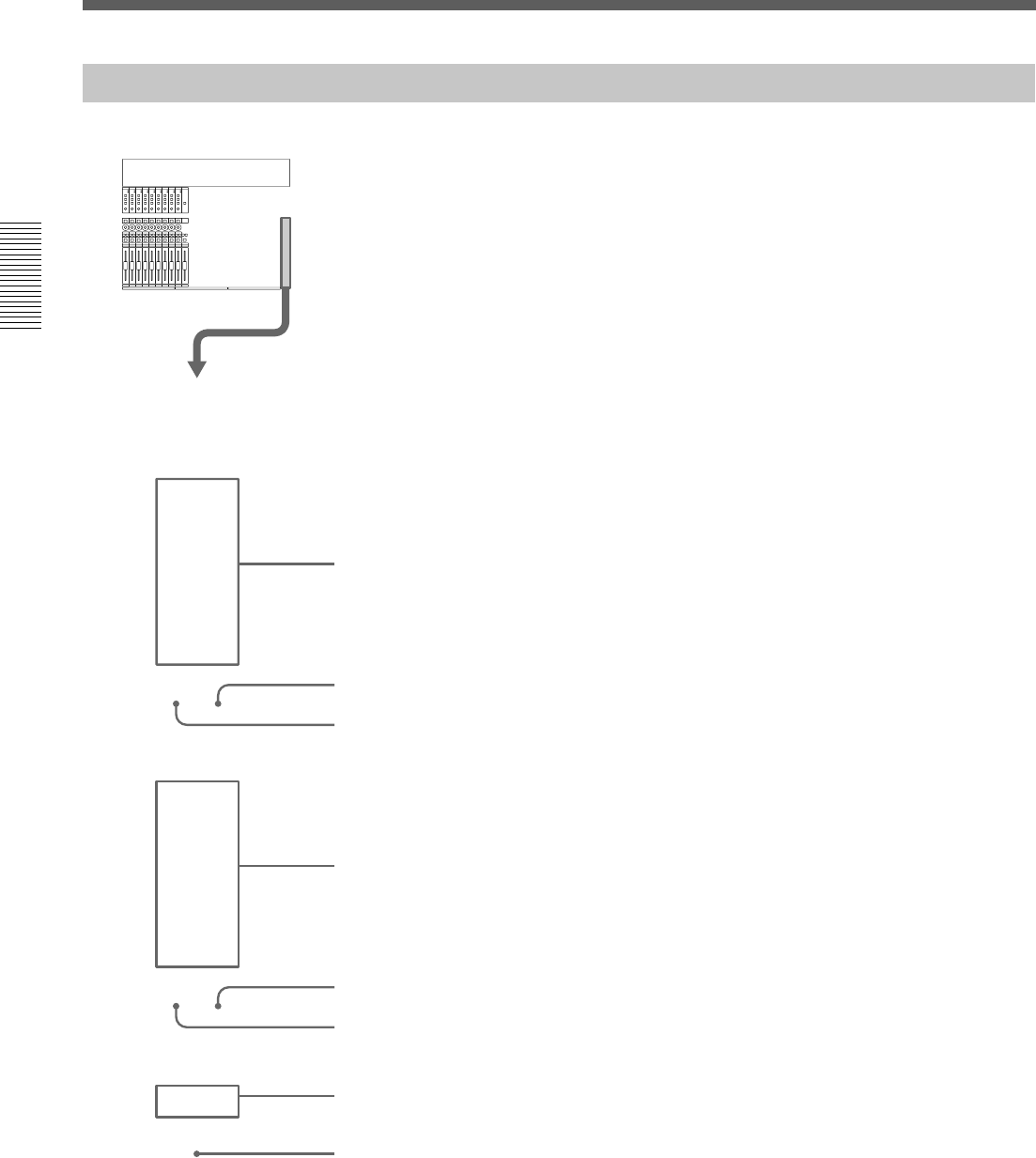
Music Production
Personal computer
Direct box
Keyboard
Microphones
Effect processors (analog)
MIDI multi-port box
from MIDI OUT to MIDI IN to LINE IN to IN A
to INSERTION
(INPUT/OUTPUT)
from AUX SEND to AUX RET to 2TR IN from PGM from CR MONITOR to the slot
(DMBK-R106)
Digital reverb
Effect processor (digital) DAT
Monitor speakers
ADAT
ADAT
ADAT
Connection Examples
9
Chaper 1 Overview
Chaper 1 Overview
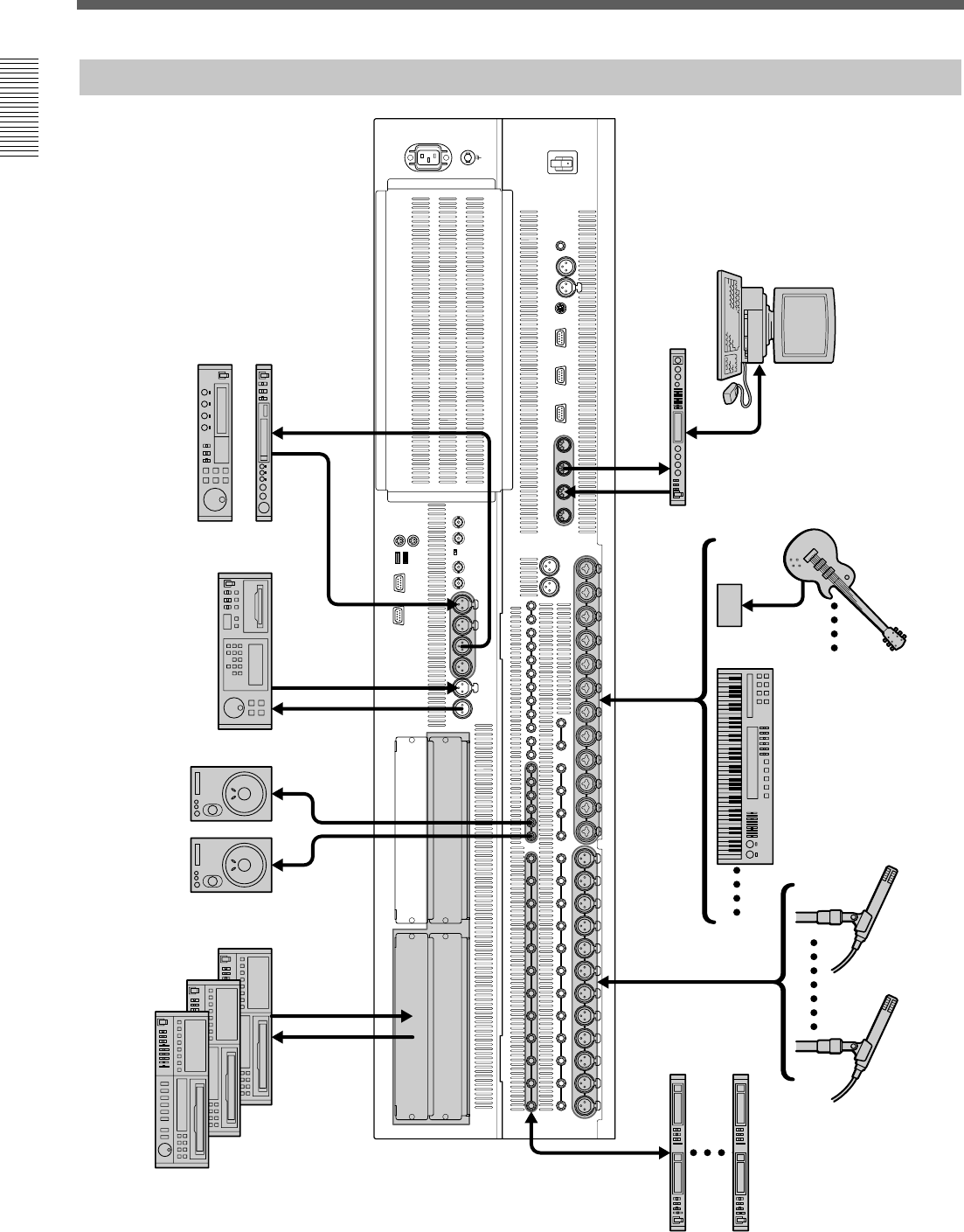
Live Recording
10
Chapter 2 Locations and Functions of Parts and Controls
Chapter 2 Locations and Functions of Parts and Controls
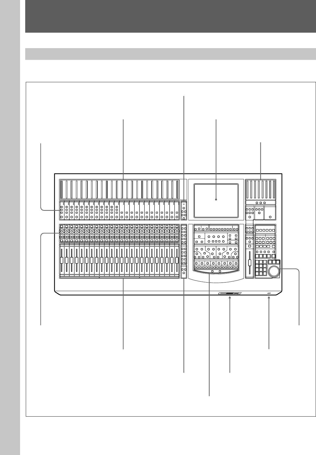
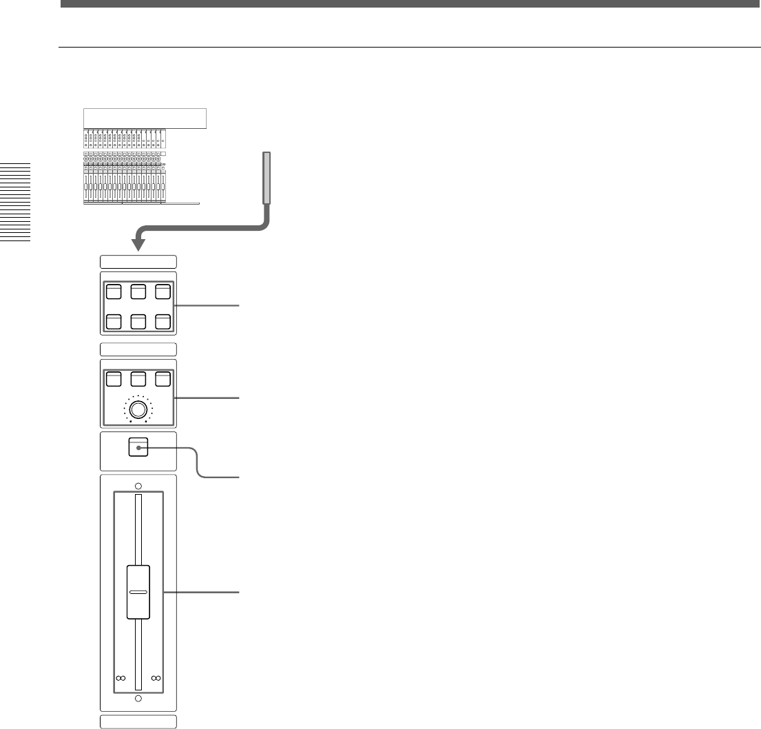
Analog Head Amplifier panel (11) Master panel (22)
Channel Strip panel (12)
Channel Fader
Assignment panel (16)
Parameter Setting panel (17)
Floppy disk drive
Headphones connector (22)
Automation
panel (25)
Locations and Functions of Parts and Controls
Composition of the Front Panel
For details, refer to pages indicated in parentheses.
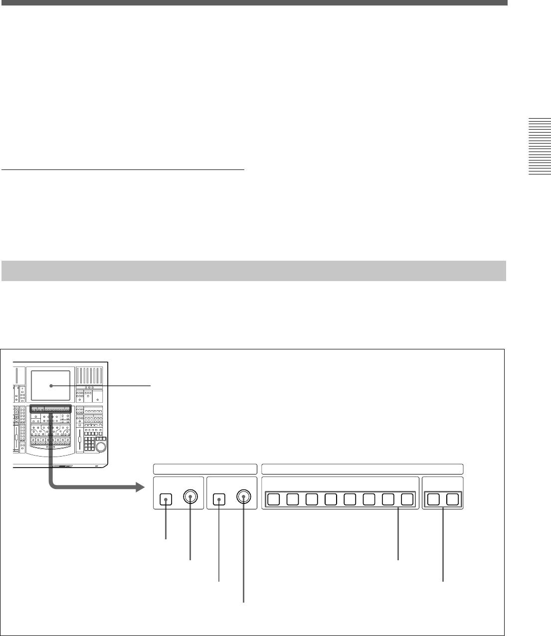
Talk-Back panel (14)
Channel Meter panel (11) Display section (17)
Chapter 2 Locations and Functions of Parts and Controls
11
Chapter 2 Locations and Functions of Parts and Controls
Chapter 2 Locations and Functions of Parts and Controls
1 OVER (analog head amplifier peak) indicators
Lights when the input level reaches the level where the
analog head amplifier starts to clip. The clip level is
about -6 dBFS.
2 SIGNAL (analog head amplifier signal)
indicators
Lights when the signal is input to the analog head
amplifier. The level at which the SIGNAL indicator
lights is about -40 dBFS.
Note
The OVER indicator and SIGNAL indicator are active
only when the input signal is routed to any channel
using the input router.
3 +48V button
Press this button to send + 48 V power to the
microphone connected to the IN A connector (XLR
connector) on the rear panel.
12
Chapter 2 Locations and Functions of Parts and Controls
Chapter 2 Locations and Functions of Parts and Controls
Locations and Functions of Parts and Controls
Channel Strip Panel
13
Chapter 2 Locations and Functions of Parts and Controls
Chapter 2 Locations and Functions of Parts and Controls
For example, the AUX 1 button is lit in the PANS
section, this control operates as control for the send
volume of AUX 1.
For detailed information on the Assignment panel, see page
16.
Indication of the PAN control
When the PAN controls are operating, the operation
status is displayed on the control using the LEDs.
When PAN is ON: LEDs from the center LED to the
one corresponding to the panning position are lit.
If you set the CUT button to ready mode beforehand,
the button’s operation is stored as automation data.
For detailed information on how to set the CUT button to
ready status, see page 38.
For detailed information on how to save it as automation
data, see page 98.
4 SOLO button
Press this button so that it lights, to listen to the signal
of the corresponding channel in PFL, AFL or SOLO
mode.
The SOLO mode is controlled from the master panel.
For details of the SOLO MODE section, see page 22.
5 ACCESS button
Press this button so that it lights, to assign the
corresponding channel to the Assignment panel and
Parameter setting panel.
This button is not used for automation function.
The display automatically switches to show the
channels settings.
You can copy the settings of the channel to another
channel by operating the ACCESS button.
Copying the setting of the channel
1Hold the ACCESS button of the source channel
down for 2 seconds or more.
The ACCESS button blinks.
2While the ACCESS button selected in step 1 is
blinking, press the ACCESS button corresponding
to the destination channel.
The settings of the channel subject to the snapshot
are copied.
The input assignments set in the AUDIO INPUT
ROUTING window are not copied.
The settings to be copied are as follows:
• TRIM • DELAY • Phase
• EQ •DYNAMICS • AUX SEND
• MTR SEND • Assignment • PAN
• Surround PAN • CUT • Fader
3Press the ACCESS button of the source channel.
The blinking ACCESS button turns on and the
copying operation is cancelled.
When PAN is OFF: Only the LED corresponding to
the panning position is lit. When the panning position
corresponds to the center LED, all LEDs are off.
When functions other than panning (AUX, TRIM and
MTR) are selected, the LED corresponding to the
volume level is lit.
Also, if you set the Pan control to ready mode
beforehand, the result of the pan control operation can
be saved as automation data.
For detailed information on how to set the pan control to
ready status, see page 38.
For detailed information on how to save it as automation
data, see page 98.
Notes
•When the signal path which has not the pan function
is selected in the FADERS section and buttons in the
PANS section are not lit, the pan control becomes
deactivated and you cannot operate this control.
—When the AUX 1 set in MONO mode is selected
in the FADERS section
—The TRIM button is lit in the fader section
•Since trimming is not subject to an automation
operation, even if TRIM is selected in either PANS
section or FADERS section, the operation cannot be
stored as automation data.
3 CUT button
This button is used to cut various signals depending on
the signal path selected in the FADERS section in the
Assignment panel. When the CUT button is lit, the
signal is cut to the signal path.
Center at PAN ON
Panning position
Lit LEDs
14
Chapter 2 Locations and Functions of Parts and Controls
Chapter 2 Locations and Functions of Parts and Controls

15
Chapter 2 Locations and Functions of Parts and Controls
Chapter 2 Locations and Functions of Parts and Controls
4 PGM button
Press this button so that it lights, to route the talkback
signal memorized on the OSC/TALK BACK window
to the PGM output.
5 STUDIO button
Press this button so that it lights, to route the talkback
signal to the studio monitor output.
6 AUX button
Press this button so that it lights, to route the talkback
signal to the AUX bus memorized on the OSC/TALK
BACK window.
7 SLATE button
Press this button so that it lights, to route the talk-back
signal to all PGM, MTR AUX outputs.
Note
Be sure to set the MEMORY button to memorize the
talkback outputs selected on the OSC/TALKBACK
window before using the MTR button 3, PGM button
4, STUDIO button 5 and AUX button 6.
For detailed information on the OSC/TALKBACK window,
see page 62.
16
Chapter 2 Locations and Functions of Parts and Controls
Chapter 2 Locations and Functions of Parts and Controls
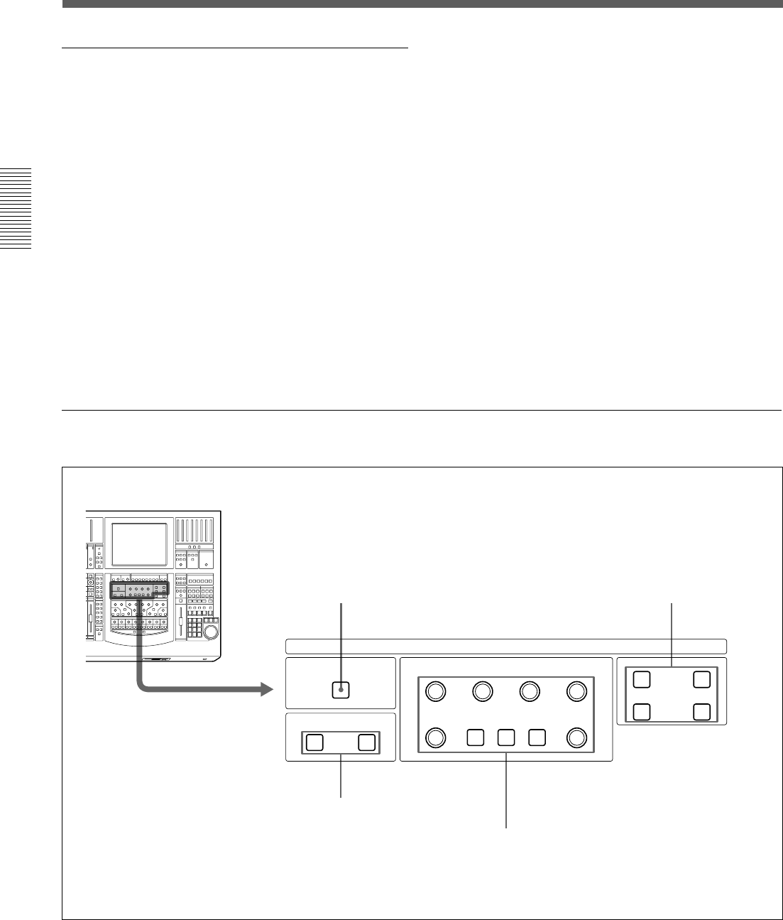
Locations and Functions of Parts and Controls
Assignment Panel
17
Chapter 2 Locations and Functions of Parts and Controls
Chapter 2 Locations and Functions of Parts and Controls
5 MTR button
Press this button so that it lights. The channel faders on
the Channel strip panel function as the send-volume
controls for the MTR bus.
6 TRIM button
Press this button so that it lights. The channel faders on
the Channel strip panel function as the trimming
volume controls.
PAGES section
The PAGES section allows you to select the pages of
24 channels assigned to the Channel strip panel.
Although the inactive pages are hidden the correct
display positions are recalled when paged.
7 Page selectable buttons
Press button (1 - 24) so that it lights, to load settings
(for the meter, WRITE button, pan control, SOLO
button, CUT button, ACCESS button and the channel
fader) for channels (1 to 24).
Press a button (25 - 48) so that it lights, to load
settings for channels (25 to 48).
8 MASTERS button
Press this button so that it lights. When this button is
lit, controls on the channel strip panel (meter, WRITE
button, PAN control, SOLO button, CUT button,
ACCESS button and the channel fader) are assigned to
24 channel strips for MTR buses (channel 1 to channel
8), AUX SEND buses (channel 1 to channel 8) and
AUX RETURN buses (channel 1 to channel 8).
INPUT BUS ASSIGN
PROGRAMMTRTRIM
Ø
DELAY
IN 1 2 3 4 5 6 7 8 L R
Display
1 ∅ button
2 TRIM control
3 DELAY IN button
4 DELAY control
5 MTR 1 to 8 buttons
6 PROGRAM L/R buttons
Parameter Setting Panel
This panel allows you to set the parameters of
channels. The ACCESS button is used to assign
channels.
18
Chapter 2 Locations and Functions of Parts and Controls
Chapter 2 Locations and Functions of Parts and Controls
Locations and Functions of Parts and Controls
INPUT Section and BUS ASSIGN section
INPUT section
This section allows you to adjust the digital input
signal. When the signal input is analog, you can adjust
the converted digital signal.
Buttons and controls in the INPUT section are only
available for snapshot automation and not dynamic
automation.
1 ∅ button
Inverts the phase of the input signal.
2 TRIM control
Trim level control for -15 dB to + 15 dB adjustment.
3 DELAY IN button
Press this button to enable the delay function.
4 DELAY control
Adjusts the delay between 0 and 999 milli seconds (at
the sampling frequency of 48 kHz).
BUS ASSIGN section
Buttons in the BUS ASSIGN section are used for the
snapshot automation function and dynamic automation
function.
5 MTR 1 to 8 buttons
Press the button to route the accessed channel to the
selected MTR bus.
6 PROGRAM L/R buttons
Press the PROGRAM L button to route the accessed
channel to the left PGM bus.
Press the PROGRAM R button to route the accessed
channel to the right PGM bus.
DYNAMICS IN
DYNAMICS
PRE EQ POST EQ
ACCESS IN
ACCESS IN
RANGE
GAIN
EXPAND
GATE
COMPRESS
DUCK
THRESHOLD RATIO ATTAC K
RELEASE
HOLD
1 DYNAMICS IN button 2 Dynamics access section
3 Dynamics insertion point buttons
4 Dynamics parameter section
DYNAMICS section

19
Chapter 2 Locations and Functions of Parts and Controls
Chapter 2 Locations and Functions of Parts and Controls
1 DYNAMICS IN button
Press this button to make the dynamics section active.
The settings on the DYNAMICS section are displayed
on the DYNAMICS window (page 47).
2 Dynamics access section
Selects the functions of dynamics parameter section
4.
ACCESS button for EXPAND/GATE: Press this
button so that the corresponding DYNAMICS window
opens. Parameters of the expander and gate can be set
using the THRESHOLD, RATIO, ATTACK, HOLD,
RANGE/GAIN and RELEASE controls in the
Dynamics Parameter section.
IN button for EXPAND/GATE: Press this button to
activate the expander and gate.
ACCESS button for COMPRESS/DUCK: Press this
button so that the corresponding DYNAMICS window
opens. Parameters of the compressor and ducking can
be set using the THRESHOLD, RATIO, ATTACK,
HOLD, RANGE/GAIN and RELEASE controls in the
dynamics parameter section.
IN button for COMPRESS/DUCK: Press this button
to activate the compressor ducking function.
Buttons in this section are not used for automation
function.
3 Dynamics insertion point buttons
Select the point where the dynamics is inserted.
PRE EQ button: Inserts the dynamics settings before
the equalizer.
POST EQ button: Inserts the dynamics settings after
the equalizer.
PRE EQ and POST EQ buttons are controlled by
snapshot automation but not dynamic automation.
4 Dynamics parameter section
The function of these buttons in this section depends
on the setting of the ACCESS button in the dynamics
access section 2.
When the ACCESS button of EXPAND/GATE in the
dynamics access section 2 is pressed: the following
parameters for the expander and gate can be set.
THRESHOLD control: Threshold
RATIO control: Ratio
ATTACK control: Attack time
HOLD control: Hold time
RANGE/GAIN control: Range
RELEASE control: Release time
When the ACCESS button for COMPRESS/DUCK in
the dynamics access section 2 is pressed: The
following parameters for the compressor and ducking
can be set.
THRESHOLD control: Threshold
RATIO control: Ratio (effective only in the
COMPRESS mode)
ATTACK control: Attack time
HOLD control: Hold time
RANGE/GAIN control: Range in the DUCK mode
and gain in COMPRESS mode.
The fully clockwise position is “AUTO” and results in
automatic gain control (when the input signal is -20
dBFs, the gain is automatically adjusted so that the
output signal is -20 dBFs).
RELEASE control: Release time
Controls and buttons in this section are used for the
snapshot and dynamic automation.
20
Chapter 2 Locations and Functions of Parts and Controls
Chapter 2 Locations and Functions of Parts and Controls
Locations and Functions of Parts and Controls
EQUALIZER section
21
Chapter 2 Locations and Functions of Parts and Controls
Chapter 2 Locations and Functions of Parts and Controls
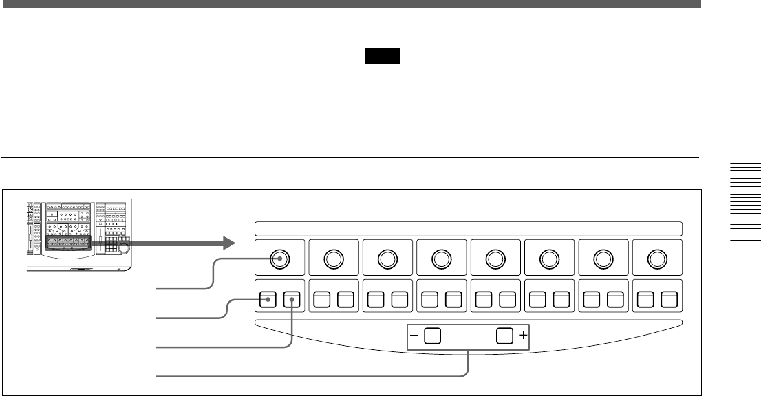
AUX SEND
CHANNEL
ON PRE
1
ON PRE
2
ON PRE
3
ON PRE
4
ON PRE
5
ON PRE
6
ON PRE
7
ON PRE
8
1 AUX SEND control
2 ON button
3 PRE button
4 CHANNEL buttons
1 AUX SEND control 2 ON button 3 PRE
button
Press the ON button so that it lights. The channel
signal is sent to the corresponding AUX bus. AUX
SEND controls 1 to 8 allow you to adjust the level of
the corresponding AUX send bus.
If the AUX SEND bus is set to stereo, the even number
controls function as the pan control.
When the PRE button is lit, the pre-fader signal is sent
to the corresponding AUX bus. When the PRE button
is not lit, the post-fader signal is sent.
The AUX SEND control, ON and PRE buttons are
available for both snapshot and dynamic automation.
4 CHANNEL buttons
Allow the access channel number to be incremented or
decremented - allowing fast use of the Assignment
panel.
7 High-cut filter section
FREQ control: Sets the cut-off frequency of the high-
cut filter.
IN button: Press this button to activate the high-cut
filter.
Note
The high-cut filter and low-cut filter operate regardless
of the setting of the IN button.
AUX SEND section and CHANNEL button
22
Chapter 2 Locations and Functions of Parts and Controls
Chapter 2 Locations and Functions of Parts and Controls
Locations and Functions of Parts and Controls
STUDIO LS SOLO MODE HEADPHONES
SETUP
DIM CUT
MTRAUXPGM
20
30
40
50
60
10
6
4
0
OVER
PGM 2T-1 2T-2
CANCEL
SOLO AFL PFL
1
LR
PGM
20
30
40
50
60
10
6
4
0
OVER
2
20
30
40
50
60
10
6
4
0
OVER
3
20
30
40
50
60
10
6
4
0
OVER
4
20
30
40
50
60
10
6
4
0
OVER
5
20
30
40
50
60
10
6
4
0
OVER
6
20
30
40
50
60
10
6
4
0
OVER
78
SOLO button on the channel
strip panel
Headphones
connector
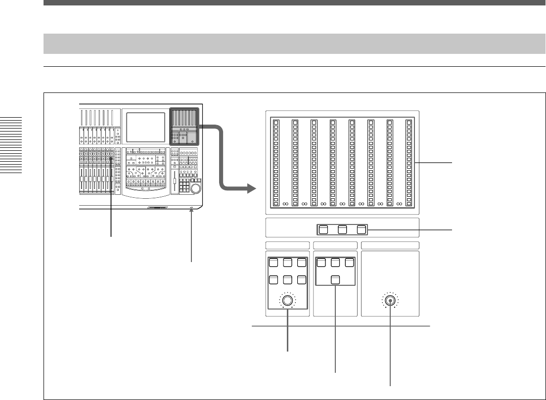
1 Master meters
2 Master meter buttons
3 STUDIO LS section
4 SOLO MODE section
5 HEADPHONES control
Buttons and controls in this section
are not used for the automation
functions.
Master Panel
Master meter/studio monitor/solo mode sections
1 Master meters
Indicate the level of the signal selected by master
meter button 2.
2 Master meter buttons
Select the signals to be displayed on the master meters.
PGM button: When this button is lit, the levels of the
PGM output signal are displayed on master meters 1
and 2.
AUX button: When this button is lit, the levels of the
output signals from AUX buses 1 to 8 are displayed on
master meters 1 to 8.
MTR button: When this button is lit, the levels of the
output signals from MTR buses 1 to 8 are displayed on
master meters 1 to 8.
3 STUDIO LS (studio speaker) section
Selects the studio monitor signal (which is output from
the STD MONITOR connector on the rear panel).
PGM button: When this button is lit, PGM signal is
monitored.
2T-1 button: When this button is lit, the signal input
to the 2TR IN 1 connector is monitored.
2T-2 button: When this button is lit, the signal input
to the 2TR IN 2 connector is monitored.
SET UP button: When this button is lit, the
MONITOR window (page 59) is displayed, showing
the STUDIO LS page. You can monitor the source
signal (EXT, AUX, or MTR) selected on the STUDIO
LS page of the MONITOR window.
DIM button: When this button is lit, the volume of
the studio monitor signal is reduced.
CUT button: When this button is lit, the studio
monitor signal is cut.
Volume control: Controls the level of the signal to the
studio monitor output.
23
Chapter 2 Locations and Functions of Parts and Controls
Chapter 2 Locations and Functions of Parts and Controls
CUT FADER
PAN
SOLO
LOGIC
SOLO MODE
SOLO SW
AFL
PFL
4 SOLO MODE section
Changes the function of the channel SOLO buttons.
SOLO button: When this button is lit, the SOLO
buttons on the channel strip panel function as
‘destructive solo’ buttons and cause all other channels
to cut.
For detailed information on how to set SOLO disabled, see
“SOLO buttons” on the MONITOR window on page 61.
Note
The solo mode affects both monitoring and the mix
output. The solo mode can be used for stereo pan and
surround sound MTR bus monitoring.
AFL (after-fader listening) button: When this button
is lit, the SOLO buttons on the channel strip panel
function as the AFL buttons. The AFL signal is sent to
the monitor, regalrdless the settings in the FADERS
section.
PFL (pre-fader listening) button: When this button
is lit, the SOLO buttons on the channel strip panel
function as the PFL buttons. The PFL signal is sent to
the monitor, regardless the settings in the FADERS
section.
CANCEL button: Provides an automatic method of
cancelling all SOLO’d channels (set in SOLO mode).
CUT
PAN
SOLO
PGM
MTR
AFL/PFL
5 HEADPHONES control
Adjusts the volume of the headphones.
24
Chapter 2 Locations and Functions of Parts and Controls
Chapter 2 Locations and Functions of Parts and Controls
Locations and Functions of Parts and Controls
Control room monitor section and PGM bus section
SOURCES
CR MONITOR
PROGRAM
ACCESS
PGM AUX MTR
SETUP DIM CUT
EXT 2T-1 2T-2
10
5
0
5
10
20
30
40
60
10
5
0
5
10
20
30
40
60
25
Chapter 2 Locations and Functions of Parts and Controls
Chapter 2 Locations and Functions of Parts and Controls
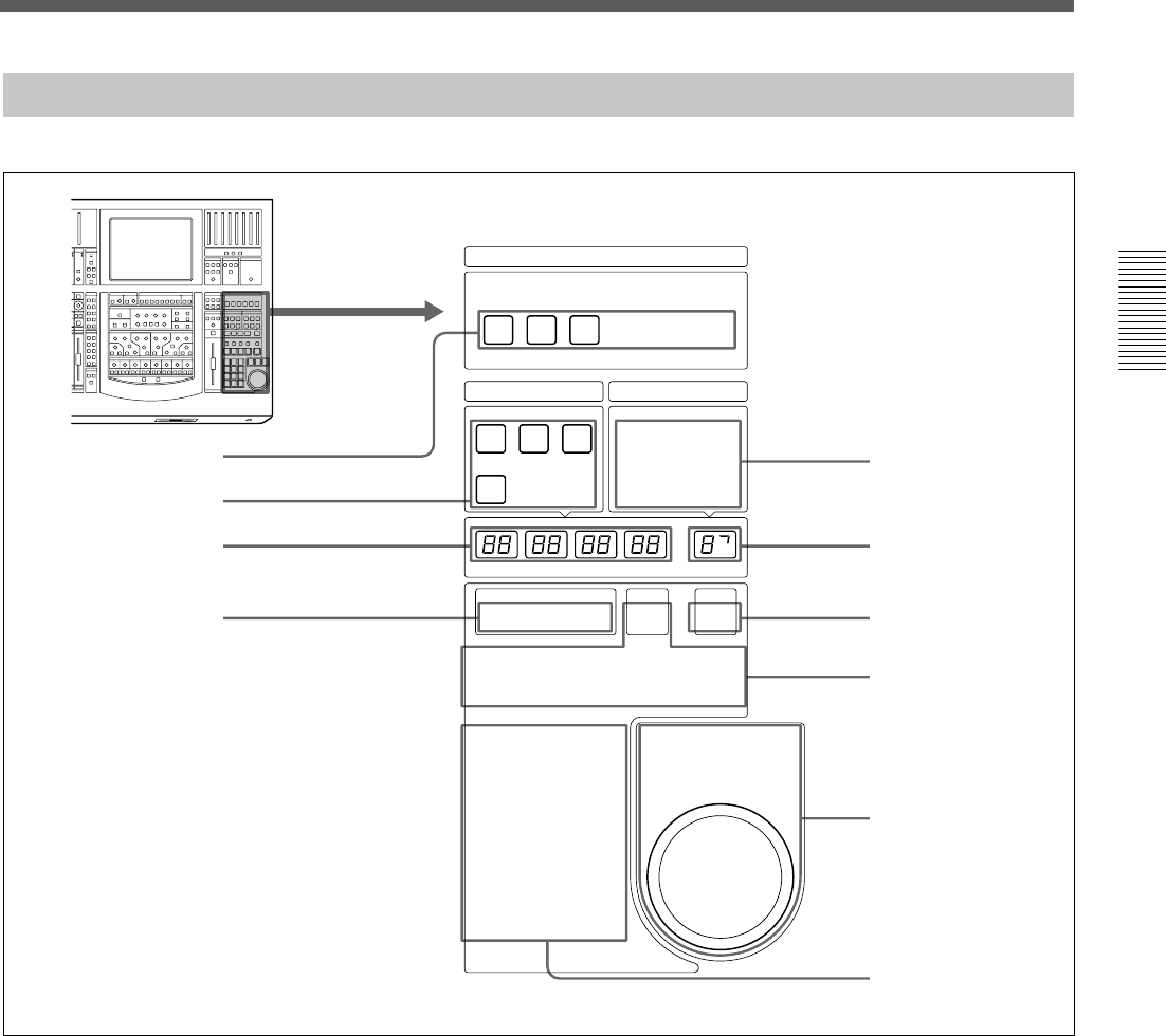
Automation Panel
TC AUTOMATION SNAPSHOT
SELECT MACHINE
1 2 3
A B SAFE
ABS
HOURS
MINUTES SECONDS
FRAMES SNAPSHOT
26
Chapter 2 Locations and Functions of Parts and Controls
Chapter 2 Locations and Functions of Parts and Controls
A button: Recalls automation data stored in the A
buffer.
B button: Recalls automation data stored in the B
buffer.
By using the A and B buttons, you can copy stored
data between the A/B buffers as explained below.
To copy the data stored in the A buffer to the
B buffer
1Press and hold the A button for more than 2
seconds, then press the B button.
The confirmation dialog box appears.
2Select [YES] on the dialog box.
Data in the A buffer is copied into the B buffer.
To copy the data stored in the B buffer to the A buffer,
press and hold the B button for more than 2 seconds,
then press the A button. Select [YES] on the dialog
box.
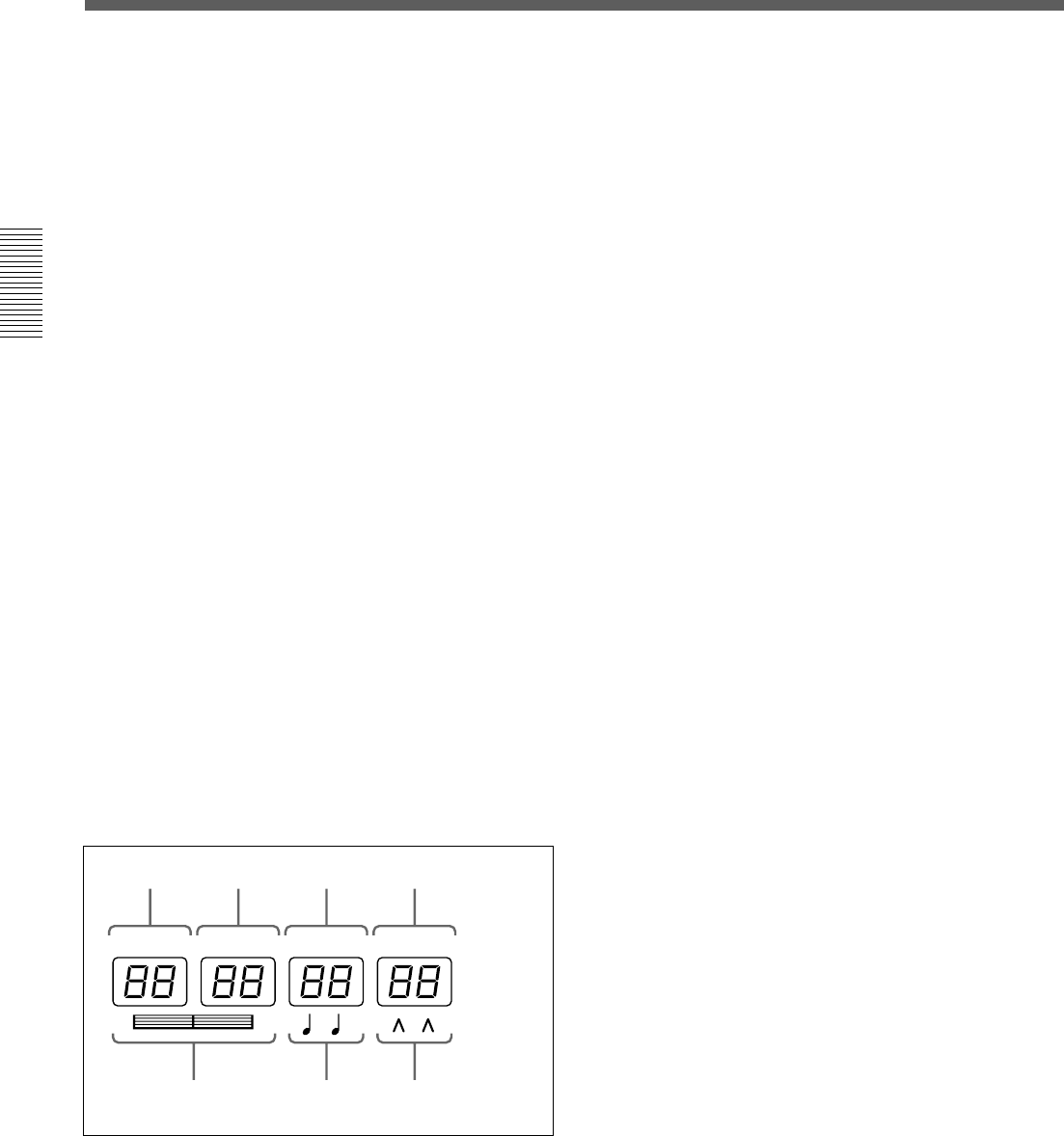
3 Timecode display window
When the LTC button is lit on the timecode input
section 4, the timecode is displayed in the window.
When the BARS button is lit, the timecode is
converted to bars, beats and the MIDI clock and
displayed.
HOURS
MINUTES SECONDS
FRAMES
Hours Minutes Seconds Frames
Bars Beats MIDI clock
4 Timecode input section
Selects the contents to be displayed in the timecode
display window 3.
LTC button: When this button is lit, the timecode
read by the built-in timecode reader is displayed in the
window.
BARS button: When this button is lit, the timecode is
converted to the bars, beats and the MIDI clock and
displayed.
When both the BARS button and SET button are lit,
you can enter the desired value using the ten key pad.
The entered value is converted to the timecode and
used.
SET button: When this button is lit, you can input the
desired timecode using the ten key pad. Also, you can
increase or decrease the timecode using the +/- buttons
and the jog dial.
When a device is selected on the SELECT MACHINE
button 1, you can input the locate time.
When this button is not lit, the timecode display
window shows the values read by the built-in timecode
reader or the tape time of the device selected by the
SELECT MACHINE button 1.
5 SNAPSHOT buttons
TC LINK button: When this button is lit, the mixer
will automatically link snapshots and mixer cues. In
this case, the value displayed on the SNAPSHOT
window is treated as the cue number.
Also, when this button is lit, you can manually recall a
snapshot which has been linked with a cue.
When the button is lit, the STORE button allows a
new cue point and snapshot to be saved and linked.
When this button is not lit, you can recall snapshot
data manually. The snapshot data is stored without the
timecode.
DELETE button: By pressing this button, the
snapshot data or the cue currently displayed on the
SNAPSHOT display window is deleted depending on
the set condition of the TC LINK button.
SETUP button: Press this button so that it lights, to
display the SNAPSHOT window or CUE window.
(When the TC LINK button is not lit, the SNAPSHOT
window opens. When the TC LINK button is lit, the
CUE window opens.)
For detailed information on the SNAPSHOT window, see
page 64, and for the CUE window, see page 66.
STORE button: Press this button so that it lights, to
store the current settings on the SNAPSHOT window
as the snapshot data. If the TC LINK button is lit, the
snapshot data is stored with the cue.
Locations and Functions of Parts and Controls

27
Chapter 2 Locations and Functions of Parts and Controls
Chapter 2 Locations and Functions of Parts and Controls
RECALL button: Press this button so that it lights, to
recall the snapshot data or the cue currently displayed
on the SNAPSHOT display window depending on the
set condition of the TC LINK button.
UNDO button: Press this button so that it lights, to
clear the last snapshot operation.
6 SNAPSHOT display window 7 SNAPSHOT
SET button
Press the SNAPSHOT SET button 7 so that it lights,
to enter the snapshot number in the SNAPSHOT
display window 6 using the ten key pad.
Also, you can increase or decrease the timecode using
the +/- buttons and the jog dial.
To execute the snapshot number, press the ENTER
key.
The number displayed on the window is treated as a
cue number when the TC LINK button is lit.
If you press the STORE button when any number is
not set on the display window, the lowest unused
number is used for the new snapshot (or cue) number.
8 Transport control keys
Controls the tape movement of the recorder selected
by the SELECT MACHINE buttons 1.
m (Rewind)/M (Fast forward)/B (Play)/x (Stop)/
z (Record)
LOCATE button: Cues up the tape of the recorder
selected by the machine controller to the locate time
previously set.
9 Jog dial section
The jog dial can be used for both machine control and
data entry.
Press the SHUTTLE +/- button so that it lights, to
control the device selected by the SELECT
MACHINE buttons 1 in shuttle mode.
There may be devices that can not be controlled in shuttle
mode.
The jog dial can also be used to change data values,
for example, by pressing the SET button under the
SNAPSHOT display window, the dial adjust the
SNAPSHOT number.
0 Ten key pad
When the SET button is lit in the Timecode input
section 4, you can enter a value in the timecode
display window, using the ten key pad.
When the SNAPSHOT SET button 7 is lit, you can
enter a snapshot number in the SNAPSHOT display
window, using ten key pad.
Pressing the ENTER key accepts the entered value
that is displayed on the window.
28
Chapter 2 Locations and Functions of Parts and Controls
Chapter 2 Locations and Functions of Parts and Controls
Locations and Functions of Parts and Controls
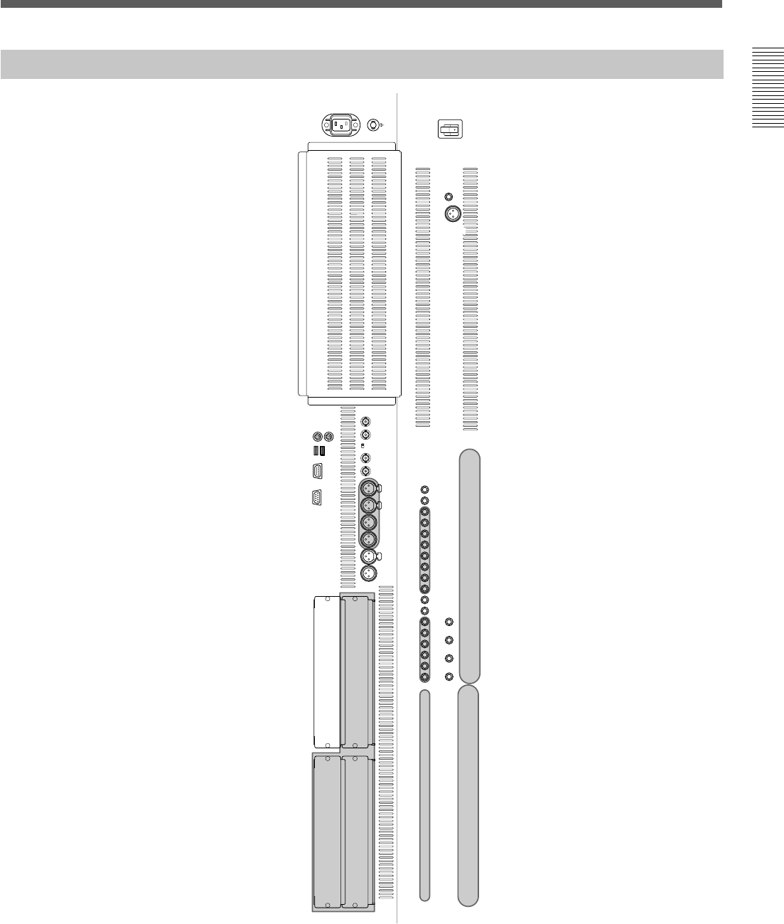
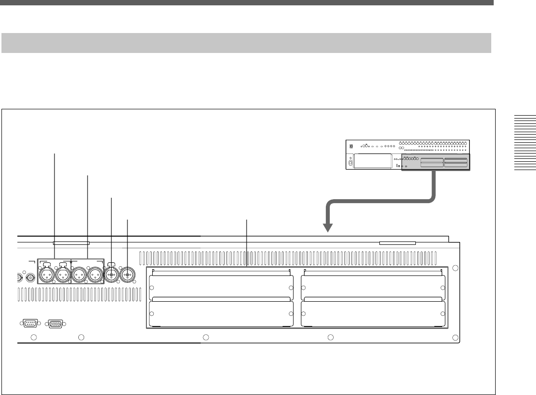
Elements of the Rear Panel
29
Chapter 2 Locations and Functions of Parts and Controls
Chapter 2 Locations and Functions of Parts and Controls
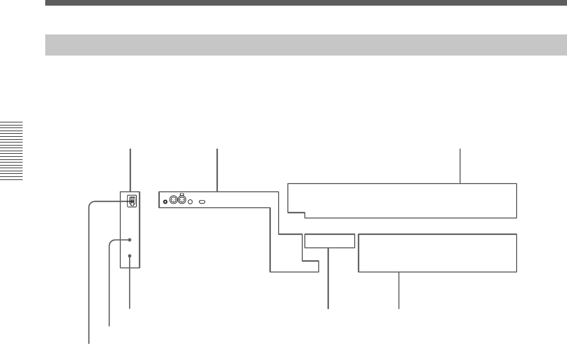
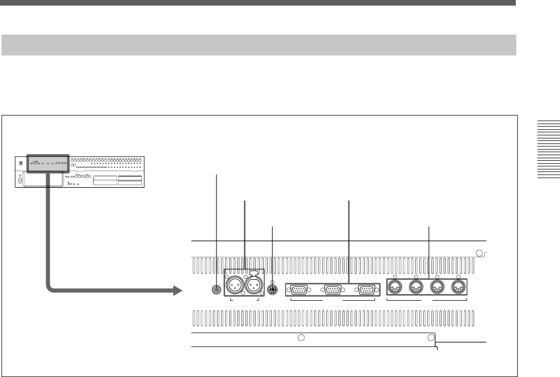
Control Signal Connectors
FOOT SW TIME CODE PC PORT REMOTE
OUT 1 THRU OUT IN MTC
PUSH
OUT 2 IN
MIDI
1 FOOT SW connector
2 TIME CODE connectors
3 PC PORT connector
4 REMOTE connectors
5 MIDI connectors
1 FOOT SW connector (Phone jack)
Connect the foot switch (not supplied) to control the
remote automation functions.
2 TIME CODE connectors (XLR 3-pin)
IN connector: Inputs the timecode signal from an
external device.
OUT connector: Outputs the timecode to an external
device.
3 PC PORT connector (Mini DIN 8-pin)
Connect the host computer.
4 REMOTE connectors (D-sub 9-pin)
IN connector: For expansion use in future.
OUT 1/2 connectors: Used for connecting to an
external device such as VTR. You can control the 9-pin
devices using the transport control keys on the
automation panel.
Control signal connectors (part 1)
5 MIDI connectors (DIN 5-pin)
MTC connector: Inputs the MTC (MIDI timecode)
used in automation operation.
MIDI IN connector: Used for connecting incoming
MIDI data, including remote control of faders, pan,
cuts and snapshots, functions depend on the settings of
the MIDI window.
MIDI OUT connector: Used for outgoing MIDI
messages, including MIDI machine control and front
panel tallies (faders, cuts and pan).
MIDI THRU connector: Outputs the signal input
from the MIDI IN connector via a buffer.
For connection examples, see page 7, for detailed
information on connectors, see “Specifications” on page
110, and for signal flow, see “Block Diagram” on page 121.
30
Chapter 2 Locations and Functions of Parts and Controls
Chapter 2 Locations and Functions of Parts and Controls
Locations and Functions of Parts and Controls
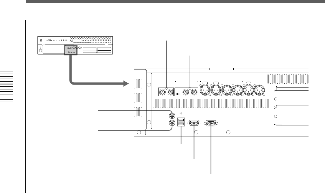
PUSHPUSH PUSH
SERIALUSBMOUSE MONITOR
KEYBOARD
REF VIDEO REF WORD AUX RET AUX SEND 2TR IN PGM
(AUTO 75Ω)IN
7/8 5/6 7/8 5/6
OUT
75Ω
ON OFF
6 REF VIDEO connectors
7 REF WORD connectors and 75 Ω switch
8 MOUSE connector
9 KEYBOARD connector
0 USB interface connector
qa SERIAL connector
qs MONITOR connector
6 REF VIDEO (reference video signal) connectors
(BNC type)
Input/output connectors for NTSC or PAL reference
video signals for synchronizing with an external
device. These connectors are loop-through. When the
loop-through output is not used, the input connector is
automatically terminated at 75 ohms.
7 REF WORD (reference word sync signal input/
output) connectors (BNC type) and 75 Ohm switch
Input/output connectors for synchronizing with an
external device.
REF WORD IN connector: Inputs the word sync
signal.
75 Ohm switch: Must be switched correctly.
Normally set this switch to ON. When you send the
work sync signal to other machines via the type T BNC
relay connector, set this switch to OFF.
REF WORD OUT connector: Outputs the word sync
signal.
8 MOUSE connector (Mini DIN 6-pin)
Used for connecting an external mouse (PS/2 type).
9 KEYBOARD connector (Mini DIN 6-pin)
Used for connecting a standard computer keyboard
(PS/2 type).
0 USB interface connector
For expansion use in future.
qa SERIAL connector (D-sub 9-pin)
For expansion use in future.
qs MONITOR connector (D-sub high density 15-
pin)
Used for connecting a standard computer’s monitor to
repeat the DMX-R100 on board display.
Control signal connectors (part 2)
31
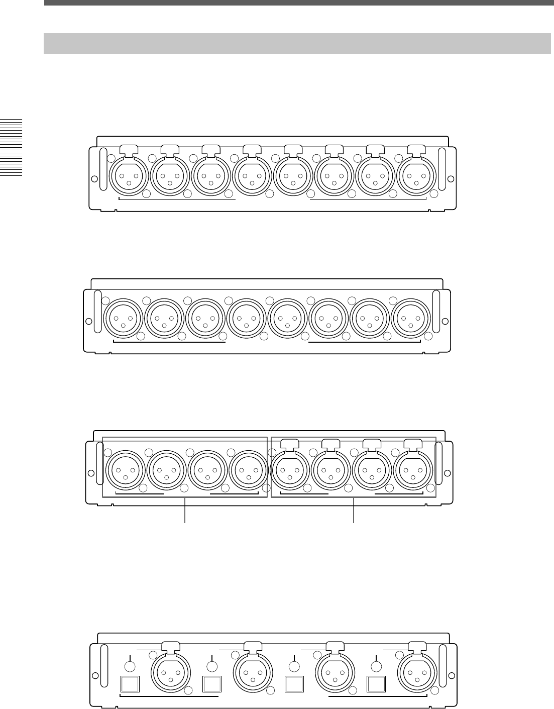
Chapter 2 Locations and Functions of Parts and Controls
Chapter 2 Locations and Functions of Parts and Controls
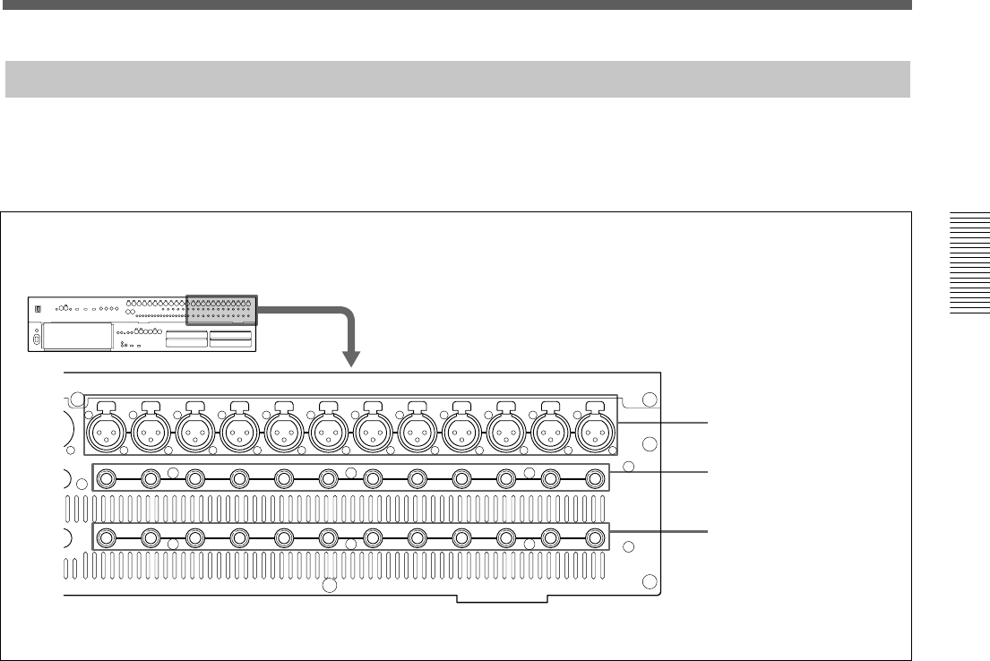
13 12 11 10 9 8 7 6 5 4 3 2 1
PUSHPUSHPUSHPUSHPUSHPUSHPUSHPUSHPUSHPUSHPUSHPUSH
12 11 10 9187654321
12 11 10 9 8 71654321
INSERTION
IN B
IN A
Analog Signal Connectors
1 IN A connectors
2 IN B connectors
3 INSERTION connectors
1 IN A (analog input A) connectors 1 to 12 (XLR
3-pin)
These connectors are enabled when the INPUT B
button on the analog head amplifier panel is not
pressed.
The IN A 1 to 12 connectors are equipped with 48 V
power for condenser microphones, each channel
feature a front panel 48 V switch
2 IN B (analog input B) connectors 1 to 12 (1/4”
TRS jack)
These connectors are enabled when the INPUT B
button is pressed.
3 INSERTION (insertion input/output)
connectors 1 to 12 (1/4” TRS jack)
Used for connecting external effectors the inserts are
analog and positioned before the analog to digital
converters.
For the pin assignment of the INSERTION connectors, see
page 111.
Analog Connectors (part 1)
For connection examples, see page 7, for detailed
information on connectors, see “Specifications” on page
110, and for signal flow, see “Block Diagram” on page
121.
32
Chapter 2 Locations and Functions of Parts and Controls
Chapter 2 Locations and Functions of Parts and Controls
Locations and Functions of Parts and Controls
33
Chapter 2 Locations and Functions of Parts and Controls
Chapter 2 Locations and Functions of Parts and Controls
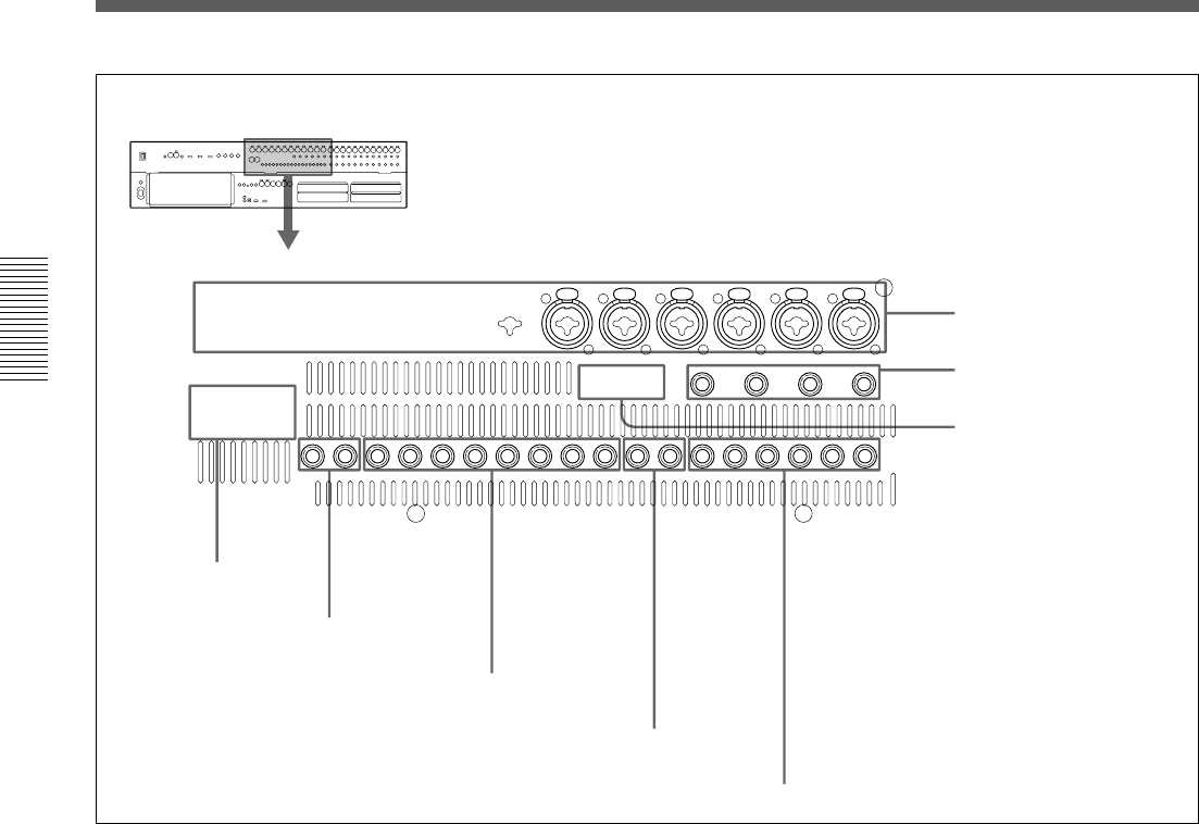
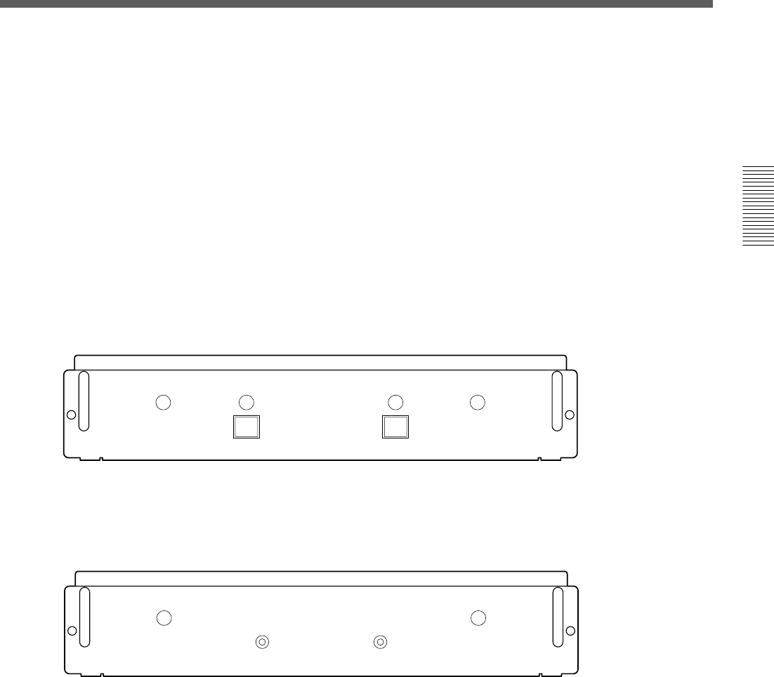
Digital Signal Connectors
SLOT 2
SLOT 4
SLOT 1
SLOT 3
PUSHPUSH PUSH
SERIAL MONITOR
WORD AUX RET AUX SEND 2TR IN2 PGM
N
7/8 5/6 7/8 5/6
OUT
1 AUX RET connectors
2 AUX SEND connectors
3 2TR IN 2 connector
4 PGM connector 5 Slots 1 to 4
For connection examples, see page 7, for detailed
information on connectors, see “Specifications” on page
110, and for signal flow, see “Block Diagram” on page 121.
1 AUX RET (auxiliary return) connectors (XLR
3-pin)
Inputs the digital signals processed by the external
digital effectors.
Connectors 5 and 6 are for AUX-return channel 5 and
channel 6.
Connectors 7 and 8 are for AUX-return channel 7 and
channel 8.
2 AUX SEND (auxiliary send) connectors (XLR 3-
pin)
Outputs the digital signals assigned to AUX sends 5
and 6 (or 7 and 8).
3 2TR IN 2 (two-track signal input) connector
(XLR 3-pin)
Inputs the digital audio signals from a 2-channel
digital recorder for monitoring.
4 PGM (program signal output) connector (XLR
3-pin)
Outputs the 2-channel digital PGM signal.
5 Slots 1 to 4 (slots for optional boards)
Insert the optional boards here.
For details of how to insert these boards, contact your Sony
dealer.
For detailed information on optional boards, see the next
page.
34
Chapter 2 Locations and Functions of Parts and Controls
Chapter 2 Locations and Functions of Parts and Controls
7
/
8
SAMPLING RATE CONVERTER DI
DMBK-R104
PUSH PUSH PUSH PUSH
5
/
6 3
/
4 1
/
2
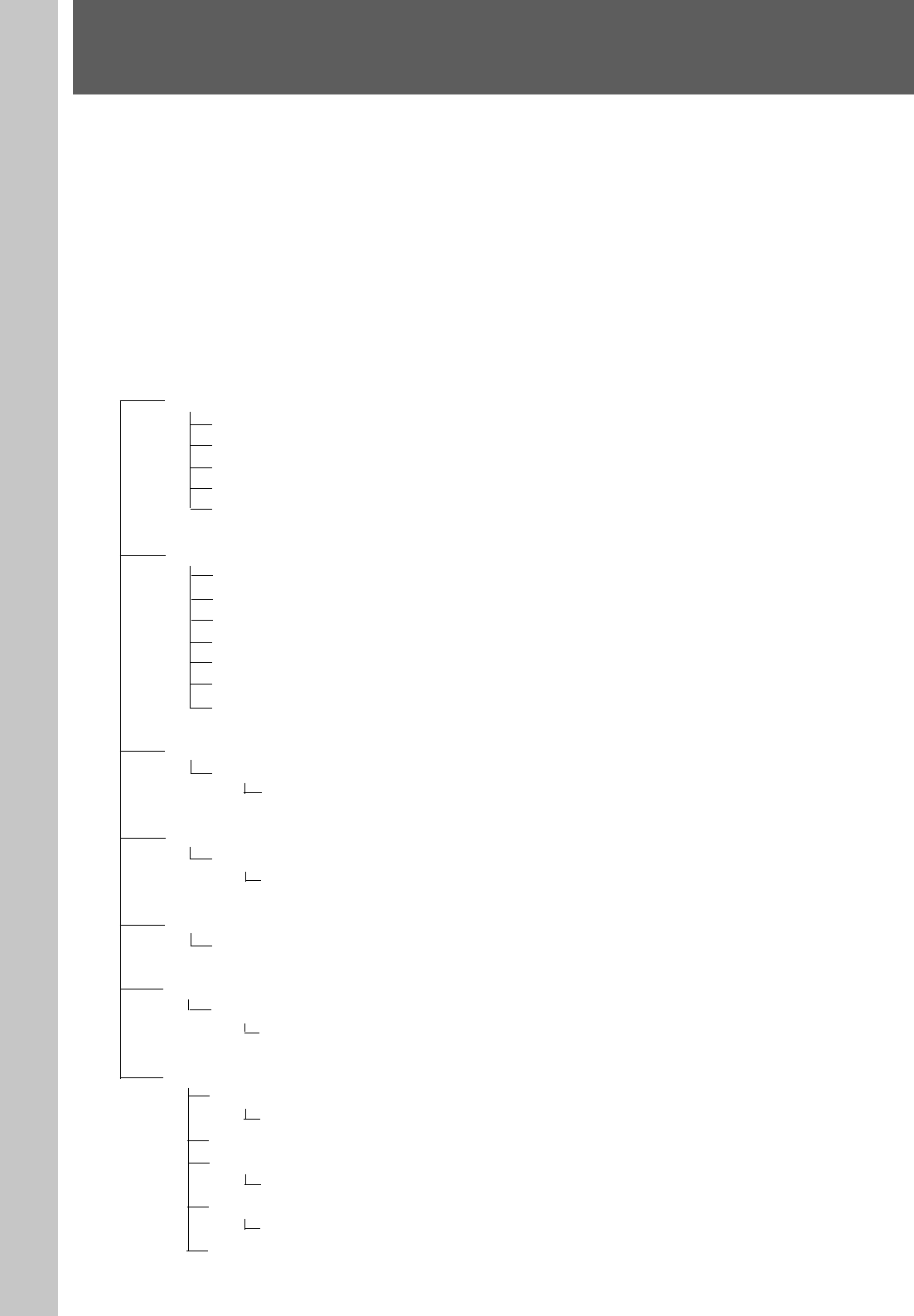
Locations and Functions of Parts and Controls
Optional Boards
8765
ANALOG INPUT(+4dB)
DMBK-R101
4321
PUSH PUSH PUSH PUSH PUSH PUSH PUSH PUSH
ANALOG OUTPUT(+4dB)
DMBK-R102
8 7 6 5 4 3 2 1
AES/EBU DI
7/8 5/6 3/4 1/2
PUSH PUSH PUSH PUSH
AES/EBU DO
DMBK-R103
7/8 5/6 3/4 1/2
Input connectors
Output connectors
DMBK-R101 8CH Analog Line In Board
Inputs balanced analog signals (+4 dB standard). The
input channels are selected on the AUDIO INPUT
ROUTING screen.
DMBK-R102 8CH Analog Line Out Board
Outputs balanced analog signals (+4 dB standard). The
output signals are selected on the AUDIO OUTPUT
ROUTING screen.
DMBK-R103 8CH AES/EBU DIO Board
Inputs/outputs AES/EBU signals at both standard
(44.1, 48 kHz) and double samples rates (88.2, 96
kHz). At double sample rates, the data transfer rate is
double the rate for standard.
DMBK-R104 8CH Sampling Rate Converter DI
Board
Inputs AES/EBU signals or optical signals such as
from a consumer CD players.
The upper sample rate of DMBK-R104 is 56 kHz and
it can not convert double sample rate signals (88.2, 96
kHz) to standard sample rates.
35
Chapter 2 Locations and Functions of Parts and Controls
Chapter 2 Locations and Functions of Parts and Controls
INTERFACE BOARD FOR ADAT
DMBK-R106
DO 1-8 DI 1-8
DMBK-R106 Interface Board for ADAT
Connects external devices such as ADAT 1) interface
boards, or external devices such as tape recorders that
have an ADAT interface.
INTERFACE BOARD FOR TDIF
DI/O
DMBK-R107
36
Chapter 3 Menu
Chapter 3 Menu
Menu Structure
The window based operating menus of the DMX-
R100 are organized in the following structure.
For detailed information on each menu, refer to the pages
indicated in parentheses.
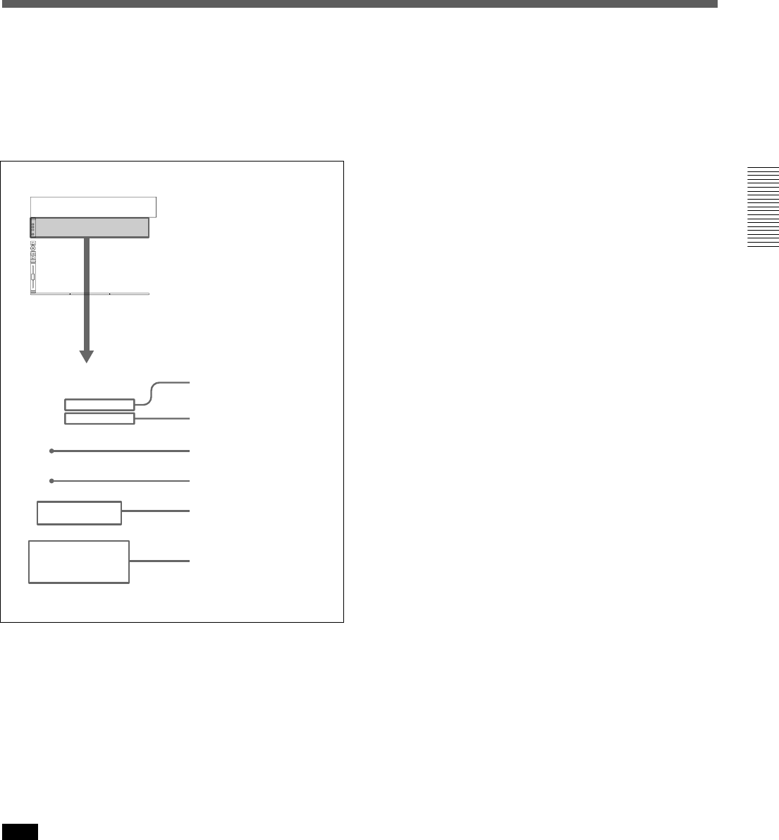
Menus related to automation (placed on the top bar on the display)
•TITLE menu (page 37)
•Snapshot display (page 38)
•Automation mode display (page 38)
Menus for controlling and monitoring the mixer
These menus open by touching the bottom menu button on the display.
CHANNEL menu
CHANNEL window (page 43)
INPUT/PAN/ASSIGN window (page 44)
EQUALIZER/FILTER window (page 46)
DYNAMICS window (page 47)
AUX SEND window (page 49)
AUDIO menu
AUDIO OVERVIEW window (page 50)
AUDIO FADER window (page 51)
AUDIO FADER GROUPING window (page 52)
AUDIO INPUT ROUTING window (page 55)
AUDIO OUTPUT ROUTING window (page 57)
MONITOR window (page 59)
OSC/TALKBACK (oscillator/talkback) window (page 62)
SNAPSHOT menu
SNAPSHOT window (page 64)
KEYBOARD window (page 86)
CUE menu
CUE window (page 66)
KEYBOARD window (page 86)
AUTOMATION menu
AUTOMATION window (page 68)
MACHINE CONTROL menu
MACHINE CONTROL window (page 70)
KEYBOARD window (page 86)
SYSTEM menu
TITLE MANAGER window (page 72)
KEYBOARD window (page 86)
MIDI window (page 75)
SYNC/TIME CODE window (page 76)
KEYBOARD window (page 86)
I/O STATUS (input/output status) window (page 81)
KEYBOARD WINDOW (page 86)
MISC SETUP window (page 84)
Chapter 3 Menu
37
Chapter 3 Menu
Chapter 3 Menu
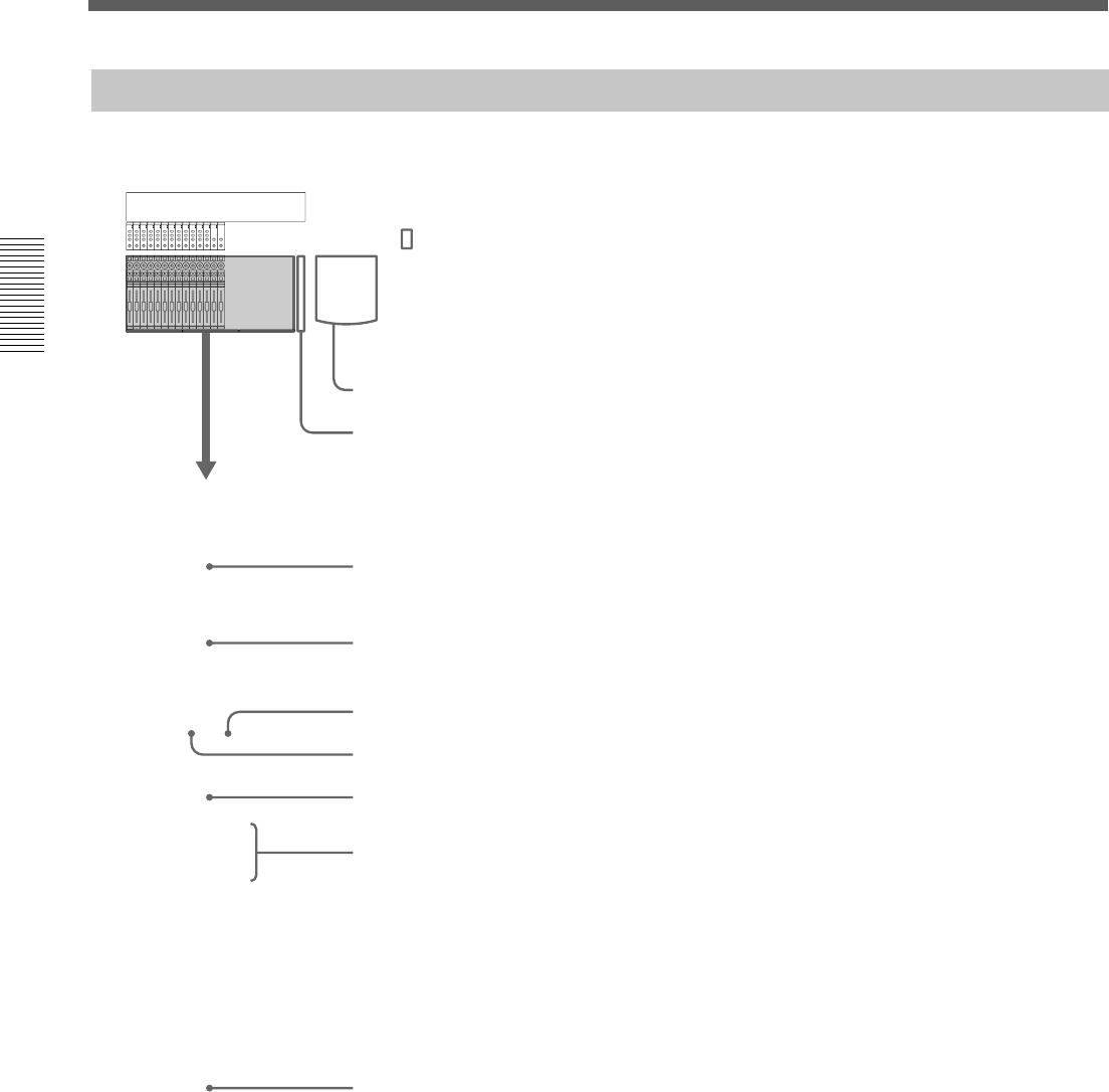
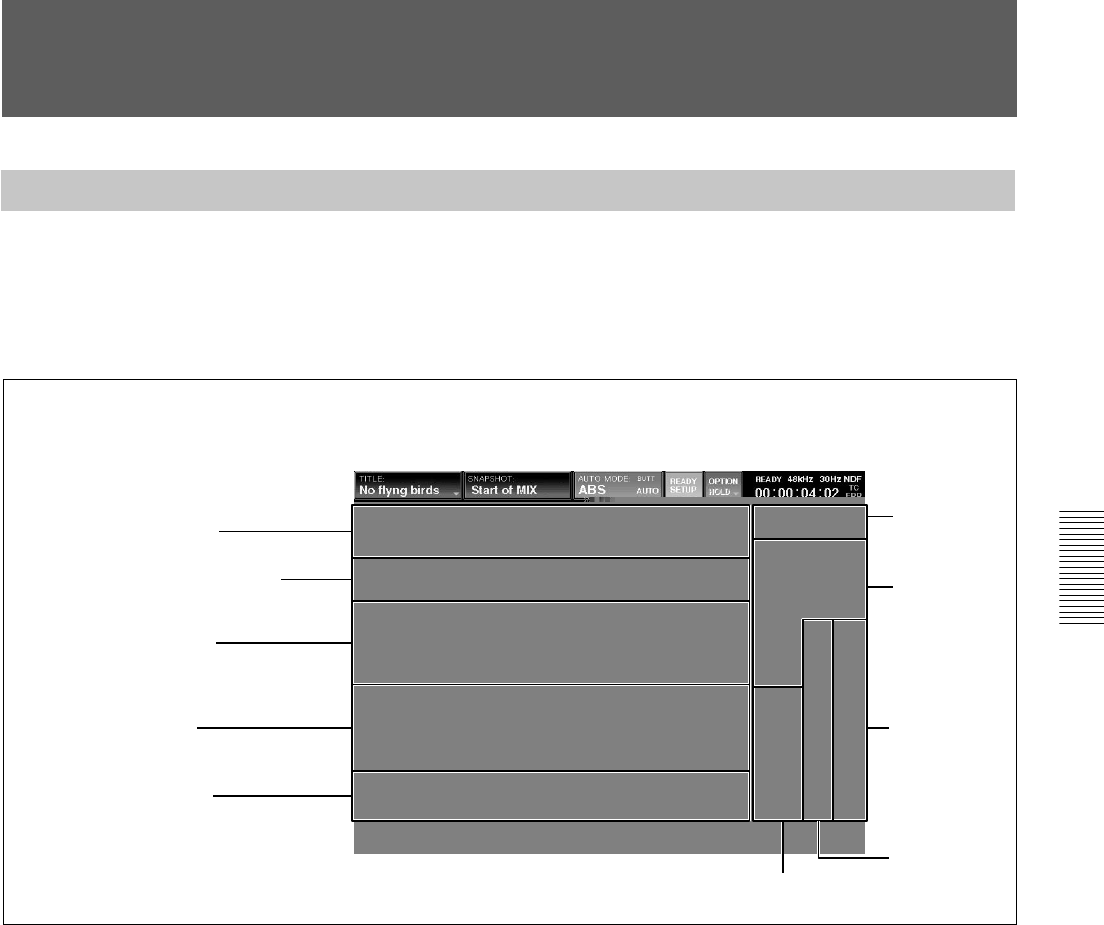
Basic Components and Functions of the Windows
Basic Components of the Windows
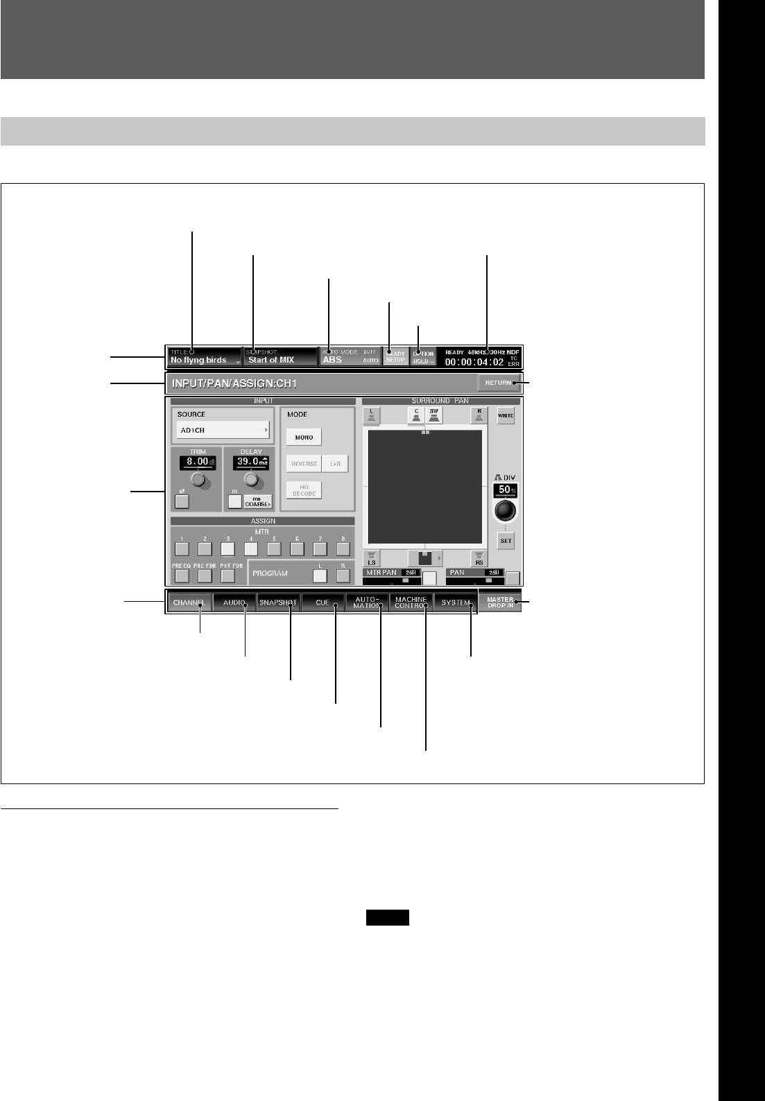
Top bar
1 TITLE button
“TITLE” is the term used in DMX-R100 for storing
and recalling all the mixer’s automation and
housekeeping functions for a project. The current
title’s name is displayed in the TITLE button.
For detailed information on the function of the TITLE
MANAGER window and how to enter the title name, see
page 72.
1 TITLE button
2 Snapshot display
3 AUTO MODE display
4 READY SETUP button
5 OPTION button
6Automation status, sampling
frequency, timecode, mode, and
error displays
Top menu bar
Touching the TITLE button opens the TITLE menu.
TITLE menu
KEEP
By selecting KEEP, the data in the work area, volatile
memory, is saved in the Current Title’s non-volatile
memory.
Notes
•When restarting or turning off the unit, the unit will
lose data that has not been SAVED (this SAVE
button is located on the TITLE MANAGER window)
or KEEP’ed.
The windows of the unit have different functions. The following pictures show the basic structure used in almost all the windows.
7 RETURN button
8 MASTER DROP IN button
9 CHANNEL button
0 AUDIO button
qa SNAPSHOT button
qs CUE button
qd AUTOMATION button
qf MACHINE CONTROL button
qg SYSTEM button
Window name
Operation window
Bottom menu bar
Chapter 3 Menu
38
Chapter 3 Menu
Chapter 3 Menu
•After executing KEEP, do not turn off the power
while the cursor indication changes to an arrow
showing that the data has been processed or while the
LED on the floppy disk drive is on. In such a case,
the unit is writing the data in the flash memory or is
storing in the floppy disk. If you turn off the unit
during this process, the Current Title may be lost.
2 Snapshot display
The name of the snapshot last recalled is displayed on
the SNAPSHOT button.
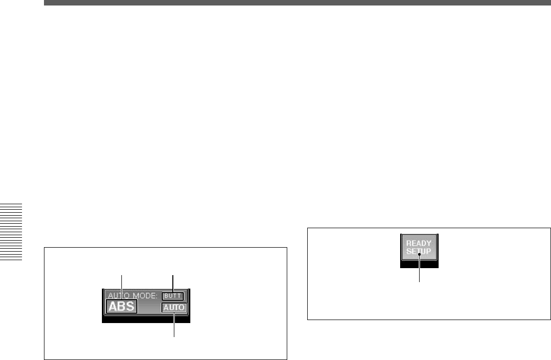
3 AUTO (automation) MODE display
Displays the Automation mode and return time mode
settings.
NEXT: Holds the position to the next event (recorded
in the dynamic automation).
TO END: Holds the position to the end and renews
the automation data. (HOLD TO END)
C Punch in mode
•NORMAL: The punch in/punch out functions are not
set.
•FOOT: Punching in/punching out using the foot
switch is set.
•AUTO: An auto punch is performed according to a
specified time entered on the Automation window.
4 READY SETUP button
Basic Components and Functions of the Windows
A Automation operation mode
•ABS: Automation is in the ABSOLUTE (absolute
value) mode. In ABS mode, the display lights red.
(When the SAFE button is lit on the console, the
display is dark red.)
•TRIM: Automation is in the TRIM (fine adjustment)
mode. In TRIM mode, the whole display is green.
(When the SAFE button is lit on the console, the
display is dark green)
•OFF: Shows the automation is off. In OFF mode, the
whole display is black.
For information on the fader operation and its results in
ABS mode and trim mode, see page 100.
B Automation return mode
Sets the automation return mode when the Drop Out
function is performed.
BUTT: When the automation is dropped out (i.e.
changes from WRITE mode to READY status), the
faders and other controls immediate jump back to the
position stored in the previous data.
RAMP: Faders and other controls ramp back to the
position stored in the previous data in a number of
frames.
Dark yellow (OFF): Normal status
Light yellow (ON): Ready setup status
(Available to set READY/SAFETY)
BAutomation return mode:
BUTT
AAutomation operation
mode: ABS
CPunch in mode: AUTO Normally, this button is dark yellow (READY SETUP
is off). In this case, the buttons, controls and switches
directly control the audio processing.
When you touch the button shown, it turns light
yellow. This allows you to select controls to the
READY status.
Now, when you operate the controls, they switch
between READY active and READY off, and the
controls do not control the audio processing. Press
READY SETUP again to revert the controls to audio
processing.
With READY SETUP on, controls switch as follows:
Buttons: Whenever you operate the buttons on the
panel and window, the READY status is switched.
Controls: Turning them clockwise results in setting
them to READY. Turning them counterclockwise
results in setting them to SAFETY. Also touching the
numerical value on the display window results in
switching READY/SAFE.
Faders: Whenever you touch the fader, READY/
SAFE is switched. Also pressing the numerical value
on the display window results in switching READY/
SAFE.
39
Chapter 3 Menu
Chapter 3 Menu
WRITE buttons on the channel strips: Whenever
you press the WRITE button, all of the controls that
can be dynamically automated in the channel are
READY’ed (i.e. are in READY status).
Notes
•The READY SETUP is automatically switched off
when the timecode is run at PLAY speed.
•When the READY SETUP button is set to ON, the
faders, controls and buttons, do not control the
sound.
5 OPTION button
This button is effective when the READY SETUP
button is light yellow. If you touch this button, the pull
down menu opens and you can select the items to be
READY’ed. When you select WRITE HOLD on the
pull down menu, HOLD is displayed on the button.
•ALL EQ: Sets the faders/equalizers of all channels to
READY.
•ALL DYNA: Sets dynamics of all channels to
READY.
•ALL AUX KNOB: Sets the AUX SEND controls of
all channels to READY.
•ALL AUX BUTTON: Sets the AUX SEND buttons
of all channels to READY.
•ALL CUT: Sets the cut setting of all channels to
READY.
•ALL ASSIGN: Sets the ASSIGN buttons of all
channels to READY.
•ALL PAN: Sets the pan setting of all channels to
READY.
•ALL FADER: Sets the faders of all channels to
READY.
•ALL CANCEL: Sets all READY to SAFE modes.
•WRITE HOLD: Whenever you select this item,
WRITE HOLD mode is switched on and off. When
WRITE HOLD is selected, HOLD is displayed on
the OPTION button. In this mode, items subject to
automation in WRITE mode will not automatically
be set to READY status when the timecode stops.
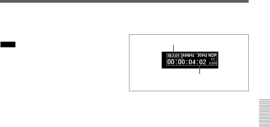
6 Automation status, sampling frequency,
timecode, mode and error displays
A Automation status display
BSampling frequency, timecode,
mode, and error display
A Automation status display
Displays the automation status mode.
•READY: Execution of automation is always possible
if the timecode advances at the PLAY speed.
•RUN: Storing/recalling of automation is possible.
•STBY: Automation data cannot be stored due to the
presence of timecode before cue, before the punch in
or after the punch out. However, you can recall
automation.
•OFF: Automation is set to OFF mode. You can
operate all of the buttons and controls manually, but
cannot store/recall automation data.
B Sampling frequency, timecode, mode, and error
display
Displays the sampling frequency and any error
indication. The timecode display is from the internal
timecode reader.
•When an error occurs on the word PLL (or video
PLL), the sampling frequency display turns red.
•When the timecode does not advance correctly, “TC
ERR” is displayed.
•When the format of the entered timecode is different
from the format setting of the unit, the timecode
mode is display in red.
7 RETURN button
Touch this button to return to the previous window
(from which the current window is displayed).
40
Chapter 3 Menu
Chapter 3 Menu
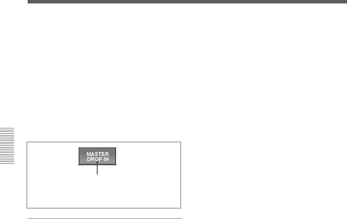
8 MASTER DROP IN button
Under normal conditions (where there are no items
subject to automation in WRITE mode), this button is
displayed in dark red.
If you touch the button while it is dark red, the button
turns light red and controls in the automation READY
status are ‘DROPed’ into automation WRITE.
If even one of the items subject to automation is
switched to WRITE mode, this button turns light red.
If you touch the MASTER DROP IN button while it is
light red, this button turns dark red and all controls in
automation WRITE are ‘DROPed’ out and return to
the READY status.
Touch this button to open the AUDIO menu which
allows you to select windows that control and display
fader functions, input/output routing and
communication functions.
The display changes to the one corresponding to the
selected window.
AUDIO menu
•OVERVIEW (page 50)
•FADER (page 51)
•FADER GROUPING (page 52)
•INPUT ROUTING (page 55)
•OUTPUT ROUTING (page 57)
•MONITOR (page 59)
•OSC/TALKBACK (oscillator/talkback) (page 62)
qa SNAPSHOT button
Touch this button to open the SNAPSHOT window
(page 64).
qs CUE button
Touch this button to open the CUE window (page 66).
qd AUTOMATION button
Touch this button to open the AUTOMATION
window (page 68).
qf MACHINE CONTROL button
Touch this button to open the MACHINE CONTROL
window (page 70).
qg SYSTEM button
Touch this button to open the SYSTEM menu which
allows you to select the windows that control system
settings.
The display changes to the one corresponding to the
selected window.
SYSTEM menu
•TITLE MANAGER (page 72)
•MIDI (page 75)
•SYNC/TIME CODE (page 76)
•I/O STATUS (page 81)
•MISC SETUP (page 84)
Light red:There are items subject to automation
in WRITE mode.
Dark red:There are items subject to automation
in READY status.
Basic Components and Functions of the Windows
Bottom menu bar
Touching one of the bottom menu buttons 9 to qg
opens a menu related to the settings of the unit.
For details on the window, see pages indicated in
parentheses.
9 CHANNEL button
Touch this button to open the CHANNEL menu which
allows you to select windows for channel processing
controls. The display changes to the one corresponding
to the selected window.
CHANNEL menu
•CHANNEL (page 43)
•INPUT/PAN/ASSIGN (page 44)
•EQUALIZER/FILTER (page 46)
•DYNAMICS (page 47)
•AUX SEND (page 49)
0 AUDIO button
41
Chapter 3 Menu
Chapter 3 Menu
Operating the Touch Panel
Changing the channel
“CH XX” which is displayed next to the window name
indicates the number of the channel.
To change the channel, press the ACCESS button on
the corresponding channel strip.
Example: To change the channels to be displayed
from CH-1 to CH-48
1Press the 25 to 48 button on the Assignment panel
to switch the faders to channels 25 to 48.
2Press the ACCESS button corresponding to the
CH-48.
“INPUT/PAN/ASSIGN: CH 48” appears on the
window.
You can also change the channel by using the +/-
CHANNEL button on the Parameter Setting panel.
Selecting the item
Many functions can be directly switched by button
icons on the display. The color of the button icons will
change to show their status.
In this manual, such an operation is described using
the phrase “Touch .. to select...”.
The color change is not described if it is not necessary.
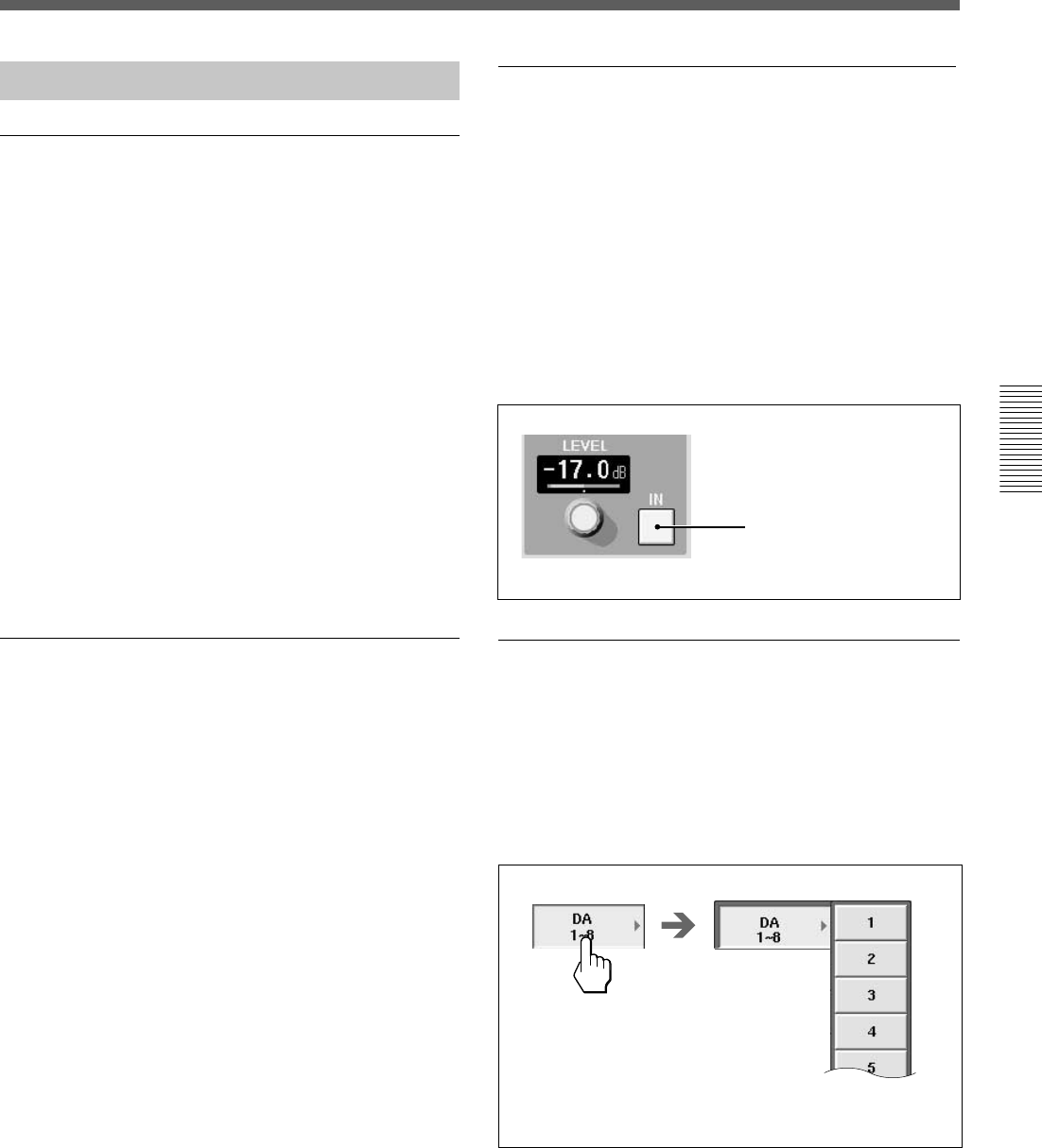
Setting the function ON/OFF (or IN/OUT)
on the window
The IN button and NOTCH button allow you to
switch the appropriate function on or off on the
EQUALIZER/FILTER window and INPUT/PAN/
ASSIGN window.
When you touch one of these buttons, the color of the
button turns green and this means the function of these
buttons is IN (or ON). When you touch one of these
buttons again, the color of the buttons turns pale and
this means that the function of those buttons is OUT
(or OFF).
Example: IN button
Blue or green: IN status
Gray: OUT status
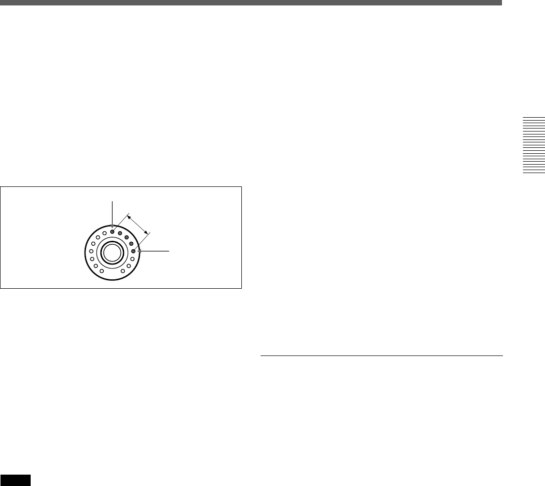
Selecting the channel or source
individually
On the AUDIO INPUT ROUTING window and
AUDIO OUTPUT ROUTING window, when you
want to select a single channel, the sub menus of two
levels open. Touch the desired channel or source to
select it.
Sub menus of two levels
42
Chapter 3 Menu
Chapter 3 Menu
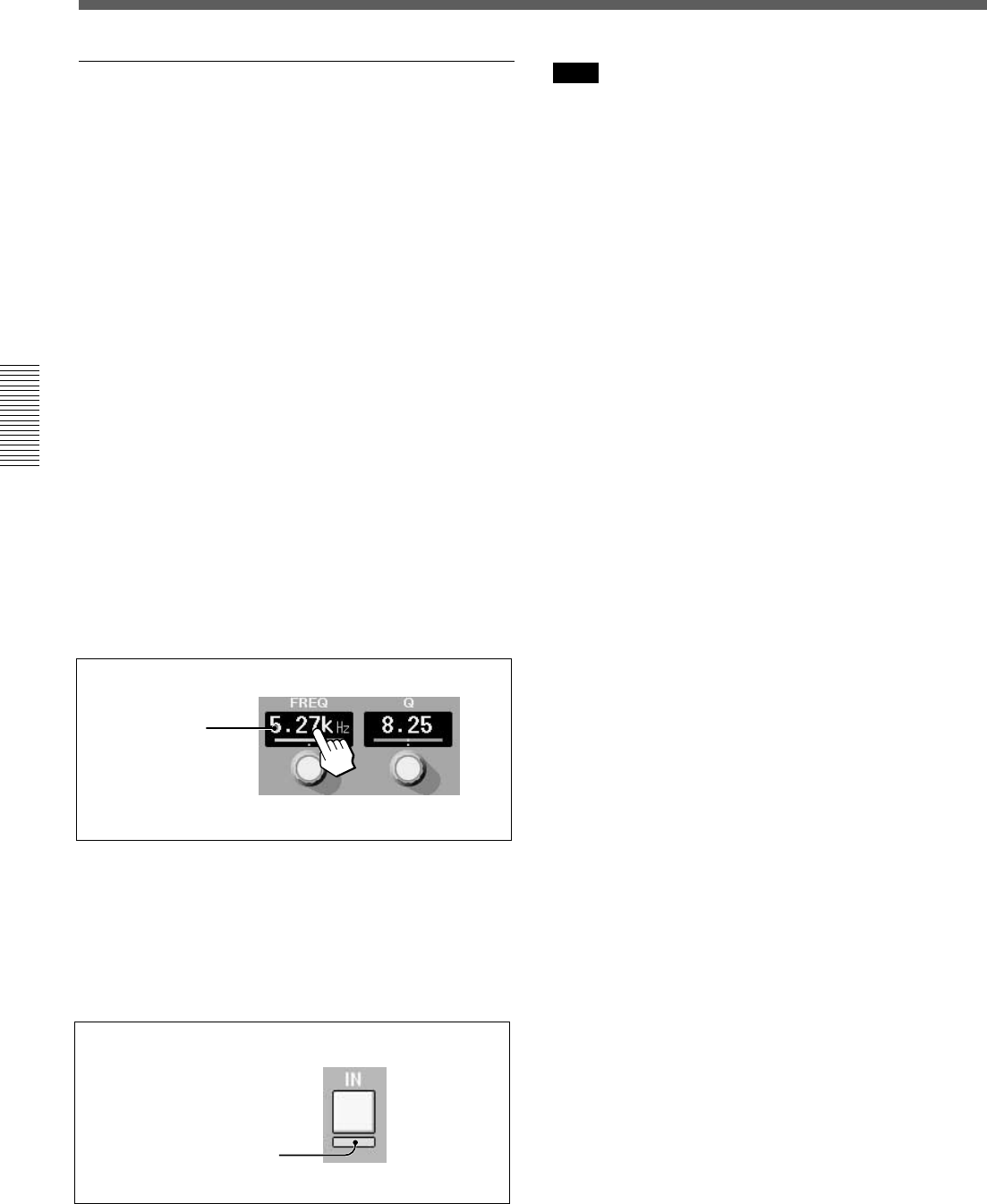
Writing data in the snapshot and
automation data
When READY SETUP button is light yellow
All of the appropriate channel processing controls on
the display can be switched into READY status by
touching the button icons by or parameter numeric
value window. The READY status is shown by either
the parameter number tuning yellow, or yellow bar
appearing under the buttons. The controls in SAFE
mode have green parameter numbers or no bar display
under the switches.
When the READY SETUP button is dark yellow
Individual channel controls that are already in the
READY status can be ‘DROP’ed’ into automation
WRITE by touching their parameter value or button
icon. The WRITE mode is displayed by touching the
parameter numbers red or by displaying a red bar
under button icons. New automation data is written
when a control is in WRITE and timecode is run at
PLAY speed.
If you touch the display window when a control is in
SAFE mode, parameter numbers turn red, but data is
not written.
Basic Components and Functions of the Windows
Touch the display
window.
READY/WRITE display on the IN/OUT button
icons on the window
In READY status, a yellow bar appears under the IN/
ON buttons.
When ‘DROP’ed’ into automation WRITE, a red bar
appears under the IN/ON buttons.
Note
Automation data written in the unit is cleared when the
power is turned off or the unit is restarted unless you
perform the KEEP operation.
Also, the snapshot data is cleared when the unit is
turned off or restarted if the KEEP function hasn’t
been performed.
For detailed information on the KEEP operation, see pages
37 and 88.
READY status: Yellow
WRITE mode: Red
43
Chapter 3 Menu
Chapter 3 Menu
Menu Windows
CHANNEL Window
To open this window, touch the CHANNEL button on
the bottom menu bar to open the menu, then select
[CHANNEL].
The CHANNEL window displays the status of the
2 Display for
INPUT/PAN/
ASSIGN
5 Channel No.
and channel
select buttons
6 SNAP ISOL
buttons
7 AUTO ISOL
buttons
1 Display for DYNAMICS
2 Display for INPUT/PAN/ASSIGN
1 Display for DYNAMICS
3 Display for EQ/FIL
4 Display for AUX SEND
1 Display for DYNAMICS
Displays the following: Dynamic ON/OFF, dynamic
insert point, active dynamics page (GATE/
EXPANDER or COMPRESSOR/DUCKING), linking,
graph and gain.
2 Display for INPUT/PAN/ASSIGN
Displays the following:MONO/STEREO channel
mode, MTR bus master, AUX SEND master and AUX
return (in stereo mode, even channel and odd channel
are linked), trim, phase inversion, delay ON/OFF and
delay value, MTR bus and PROGRAM bus
assignments, Panning and surrounding panning status
3 Display for EQ/FIL
Displays the following:
•Frequency and ON/OFF of the high -cut filter and
low-cut filter and NOTCH mode of the low-cut filter
By touching the item, the window corresponding to the item opens.
By touching the display window, the item corresponding to the display window
drops in or drops out, or switches between READY and SAFETY.
channel specified by pressing the ACCESS button on
the channel strip. When you operate the controls and
faders, the control moves are displayed on the
window.
•Frequency, ON/OFF, Q, level, characteristics
(peaking/shelving type) of the HF, HMF and LF
sections.
4 Display for AUX SEND
Displays the following: Send level to the AUX SEND
bus. Pan when the AUX SEND bus is set in stereo
mode, ON/OFF and prefader/postfader
5 Channel No. and channel select buttons
The channel select buttons allow you to increase or
decrease the channel number of the accessed channels.
6 SNAP ISOL (isolate) buttons
These buttons show the functions that are active or
isolated from snapshot recall.
7 AUTO ISOL (automation isolate) buttons
These buttons show the functions that are active or
isolated from dynamic automation.
8 Fader level display
Displays the fader level.
8 Fader level display
44
Chapter 3 Menu
Chapter 3 Menu
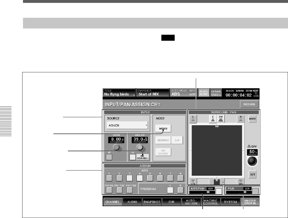
INPUT/PAN/ASSIGN Window
To open this window, touch the CHANNEL button on
the bottom menu bar, then select “INPUT/PAN/
ASSIGN.” Or, when the CHANNEL window is
displayed, touch any point of the INPUT/PAN/
ASSIGN display.
Note
When setting a channel or an aux send master to
STEREO mode, DYNAMICS, EQ, AUX SEND
LEVEL, AUX PRE, CUT , FADER and MTR SEND
operate in stereo mode.
Mode button
3 SURROUND PAN section
1 INPUT section
Unit selection button
2 ASSIGN section
1 INPUT section
SOURCE section
Displays the source currently selected.
To change the source, touch this button to open the list
of available inputs.
TRIM section
Display window: Displays the input gain trim setting
that are controlled by the TRIM control on the
Parameter Setting panel.
∅ button: Touching this button inverts the phase of
the input signal. In its normal state, the button color is
gray. When the phase is inverted, this button color
changes to green.
Delay section
Display window: Displays the setting of the
programmable delay amount that are controlled by the
DELAY control on the Parameter Setting panel.
IN button: Touch this button to turn the delay ON or
OFF on the window. In its normal state (when the
delay is off), the button color is gray. When the delay
is on, this button changes to green.
Unit selection button: Touch to select the delay mode
to SAMPLE, mS or FRAME units. Each unit has two
adjusting modes: NORMAL mode (adjusts in
minimum units) and COARSE mode (rough
adjustment).
When you change the delay mode, if the displayed
mode and actual delay amount are different units, a
yellow f appears over the unit display in the window.
MODE section
MODE button: Toggles between MONO and
STEREO link mode.
When STEREO is displayed on the button, adjacent
channels, (i.e. channels 1 and 2), operate in stereo
mode. The odd channel is L and the even channel is R.
The REVERSE, L + R and MS DECODE buttons are
active, only when the STEREO button is lit.
REVERSE button: When this button is lit, the right
and left are swapped.
L + R button: When this button is lit, the right and left
channels are mixed (L + R signal).
Menu Windows
5 PAN section
4 MTR PAN section
45
Chapter 3 Menu
Chapter 3 Menu
MS DECODE button: Inserts a middle/side decoder
to convert the odd numbered chanel ( M - Mid-
capsule) and even numbered channel (S - Side-
capsule) to Left and Right. This is only active in
STEREO mode.
These signals are converted to right and left signals
before the channel faders.
2 ASSIGN section
MTR button and PROGRAM button: Touching
these buttons results in the output of the displayed
channel being assigned to the corresponding the MTR
or PROGRAM buses.
PRE EQ button: When this button is ON, the signal
before the equalizer/dynamics circuit is sent to the
MTR bus.
PRE FDR button: When this button is ON, the signal
before the channel fader is sent to the MTR bus.
POST FDR button: When this button is ON, the
signal after the channel fader is sent to the MTR bus.
If the PRE EQ button, the PRE FADER button or the
POST FDR button is selected, the remaining two
buttons are cleared.
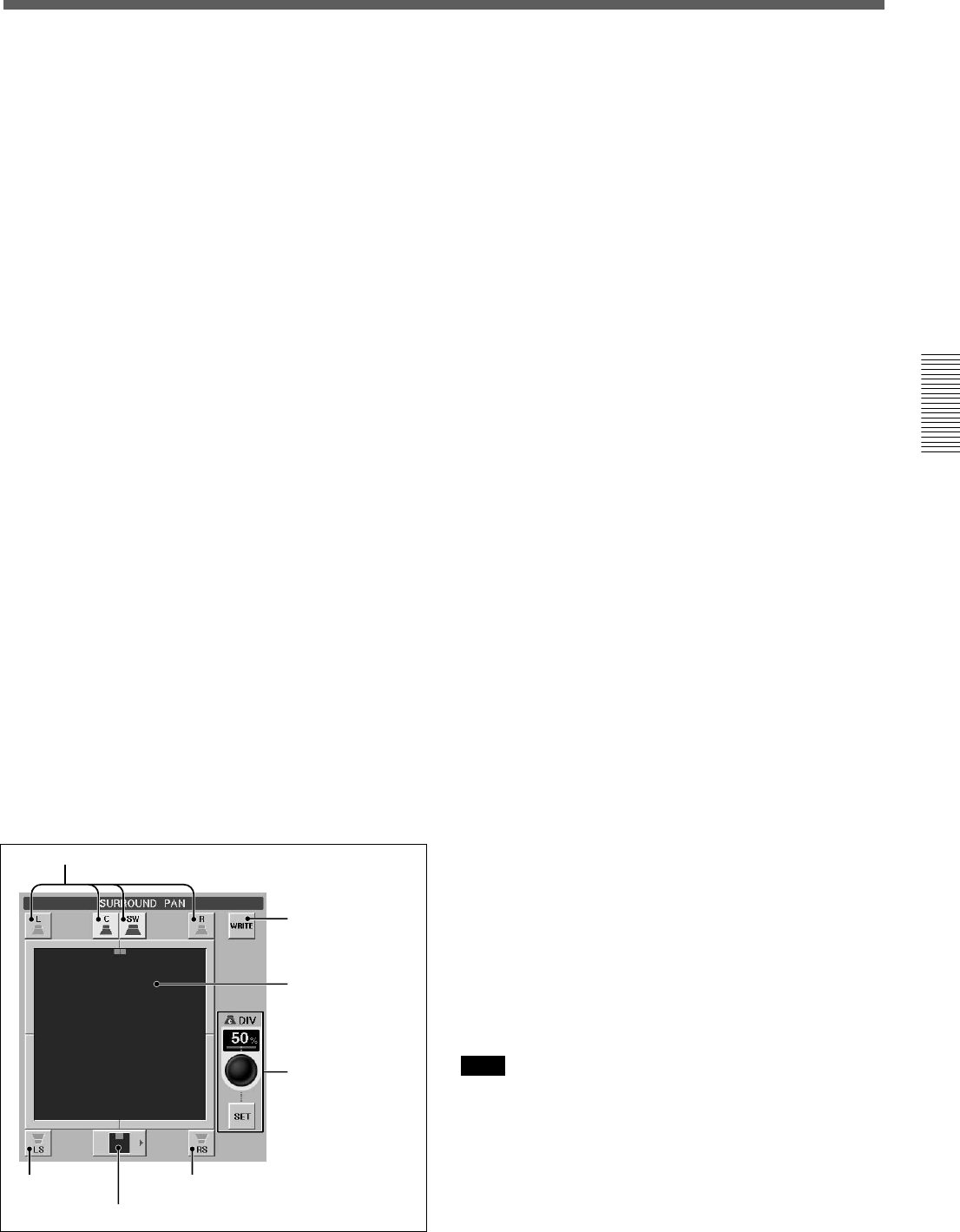
3 SURROUND PAN section
To switch the MTR buses to Surround, the
SURROUND button must be “ON” in the MTR BUS
MODE section of the MISC SET UP window.
When the unit is in normal mode, this section is not
active. For channels set to stereo link, the surround
panning for the right channel and left channel can be
set individutally.
For detailed information on the MISC SETUP window, see
page 84.
A L (left), C (center), R (right), LS (left surround) ,
RS (right surround) and SW (sub woofer) buttons
These have the same functions as the MTR button on
the unit.
The assignment of MTR buses to the surround send
outputs is as follows.
•L button t MTR 1 bus
•C button t MTR 3 bus
•R button t MTR 2 bus
•LS button t MTR 5 bus
•RS button t MTR 6 bus
•SW button t MTR 4 bus
B WRITE button
Touch this button to switch the surround pan to
READY and to DROP IN/OUT of automation
WRITE.
C Surround pan display/operation area
In surround mode, you can set the surround panning in
this area. Touch this area, then drag the icon to the
desired point.
D DIV display window, SET button and jog dial
In surround mode, by touching the SET button, you
can set the divergence value (ratio of the divergence
among L channel, center channel and R channel) using
the jog dial on the unit. The set divergence value is
displayed on the DIV window.
Touching the DIV display window allows you to set
the mode to READY and to DROP IN/OUT of
automation WRITE.
E Surround position button
Touch this button to access the nine preset surround
pan positions. You can set the surround position by
selecting the icon corresponding to the desired type
from the list.
4 MTR PAN section
Displays the panning operation status of the MTR bus.
Touch this button to set pan on or off.
Note
The MTR pan in surround mode is linked with the
LgR direction of the surround pan. When the
surround pan is set to ON, the MTR pan is set to ON.
5 PAN section
Displays the normal panning operation status. Touch
this button to set pan on or off.
A L,C,SW,R buttons
B WRITE button
C Surround pan
display/operation
area
D DIV display
window, SET
button and jog
dial
A LS button A RS button
E Surround position button
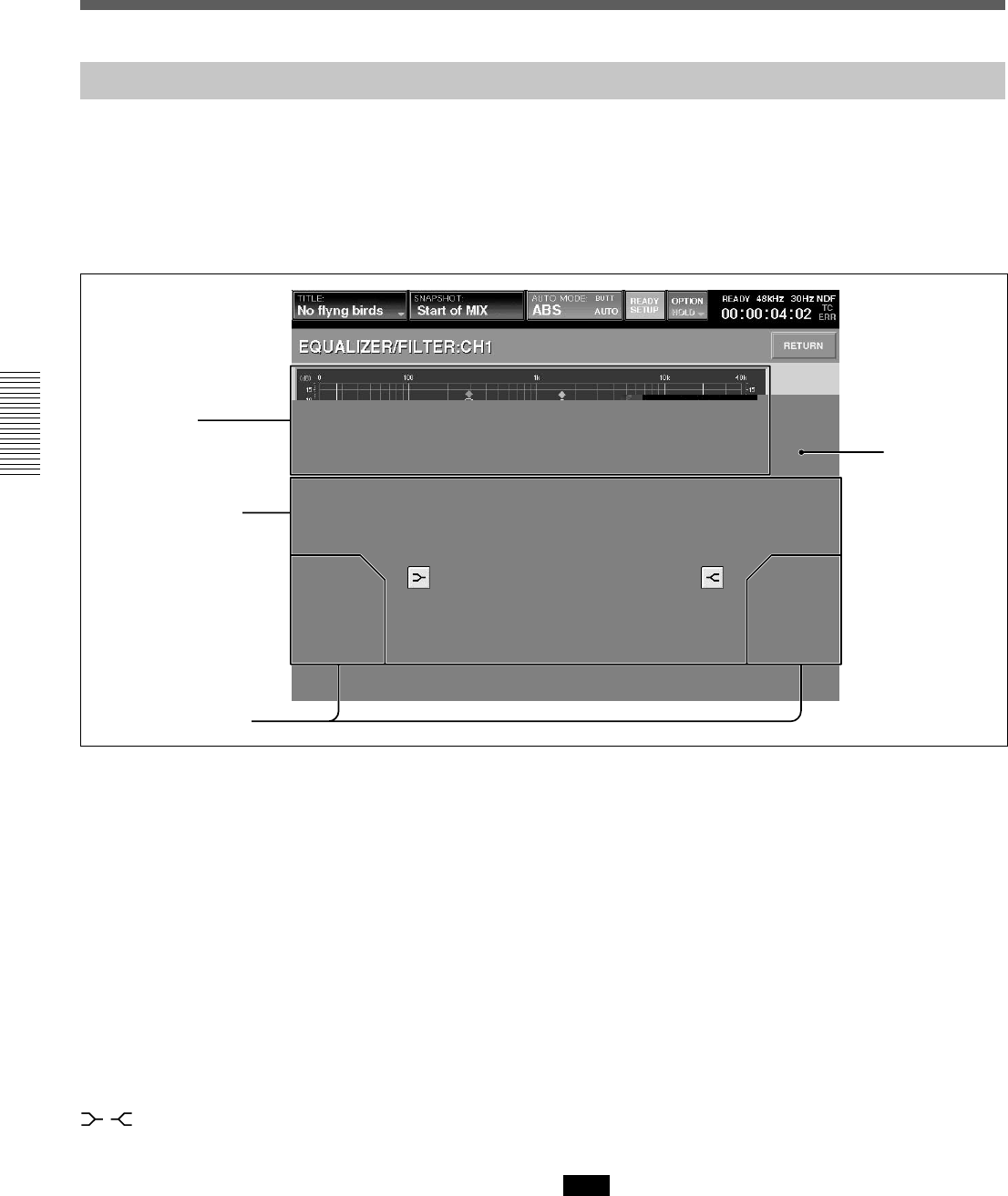
46
Chapter 3 Menu
Chapter 3 Menu
EQUALIZER/FILTER Window
To open this window, touch the CHANNEL button on
the bottom menu bar, then select “EQUALIZER/
FILTER.” Or, when the CHANNEL window is
displayed, touch any point on the EQ/FIL display
section.
This window displays the settings on the
EQUALIZER section on the Parameter Setting panel
of the unit.
If you touch the display window where the numerical
value is displayed, that item is set to READY status or
automation DROP IN/OUT.
1Frequency
characteristics
graph
2LF/LMF/HMF/HF
equalizer section
1 Frequency characteristics graph
Displays the total frequency characteristics of the
equalizers and filters.
2 LF/LMF/HMF/HF equalizer section
Displays Q, the level and in/out status of each
equalizer section.
FREQ (frequency) display: Displays the frequency
set by the FREQ control.
Q display: Displays the setting of the Q control.
LEVEL display: Displays the level set by the LEVEL
control on the unit.
IN button: This button puts each equalizer section in
and out of the circuit.
/(equalizer characteristics selector) buttons:
These buttons change the equalizer section from a
peaking equalizer to a shelving type of equalizer.
3 LF/HF filter section
FREQ (cut-off frequency) display
Displays the filter’s cut-off frequency set by the FREQ
control on the EQUALIZER section on the Parameter
Setting panel.
IN button: This button puts the filter in and out of
circuit.
NOTCH button (only for low-cut filter): This button
turns notch mode ON or OFF. When this button is lit,
the low-cut filter acts as a notch filter.
4 EQ (equalizer) IN button
Touch this button to turn on or off the whole equalizer
section. This button is linked to the IN button under
the DYNAMICS section on the Parameter Setting
panel.
Note
Even if the IN button in each equalizer section is lit,
the equalizer/filter sections are not turned on if this
button is not lit. Filters are turned on or off regardless
of the EQ IN button setting.
Menu Windows
3LF/HF filter section
4EQ IN button
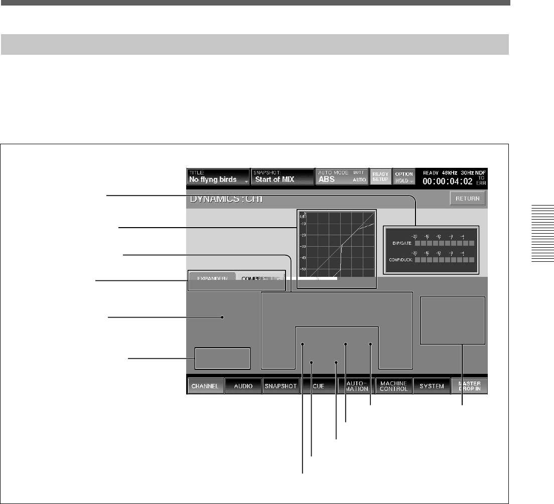
47
Chapter 3 Menu
Chapter 3 Menu
DYNAMICS Window
To open this window, touch the CHANNEL button on
the bottom menu bar, then select “DYNAMICS”. Or
when the CHANNEL window is displayed, touch any
point of the DYNAMICS display.
This window displays the settings of the
DYNAMICS section on the Parameter Setting panel.
If you touch the display window where the numerical
value is displayed, that item is set to READY status or
automation DROP IN/OUT.
7 KEY button
8 EXP/COMPRESSOR button
9 GATE/DUCK button
0 LINK button
qa KNEE button qs Function
access buttons
2 Dynamics characteristics
3 Parameter display section
4 Function selectors
5 DYNAMICS IN button
6 INSERTION POINT section
1 Gain reduction meter
Displays the gain reduction of both dynamics sections.
2 Dynamics characteristics
Displays the graph of the dynamics gain transfer
function.
3 Parameter display section
Displays the following values of the Expander/Gate or
Compressor/Ducking selected by the Function
selectors 4.
•THRESHOLD: Threshold
•RATIO: Ratio
•ATTACK: Attack time
•HOLD: Hold time
•RANGE: Range of the gate (In compressor mode,
gain )
•RELEASE: Release time
1 Gain reduction meter

48
Chapter 3 Menu
Chapter 3 Menu
4 Function selectors
Switch the function to be displayed on the Parameter
display section 3 between Expander/Gate and
Compressor/Duck.
EXPANDER/GATE tab: Touch this tab to select the
Expander/Gate function.
COMPRESSOR/DUCK tab: Touch this tab to select
the Compressor/Duck function.
5 DYNAMICS IN button
This puts the dynamics in the signal path.
Note
Even if the individual IN buttons of the EXT/GATE or
the COMP/DUCK are selected, the dynamics are not
in the circuit if the DYNAMICS IN button is out.
6 INSERTION POINT section
Switches the insertion point of the dynamics between
PRE/POST EQ.
PRE EQ button: Touch this button to insert the
dynamics processing before the equalizer.
POST EQ button: Touch this button to insert the
dynamics processing after the equalizer.
7 KEY button
Touch this button to open the sub menu that allows
you to select the key signal for the dynamics
processing.
LOCAL: Uses its own channel signal as the key
signal.
1 to 24 (or 25 to 48): Uses the signal of the selected
channel as the key signal. The audio channel is
selected using two-level channel lists.
AUX: Uses the AUX SEND signal as the key signal.
The setting of this button is common to EXPAND/
GATE and COMPRESSOR/DUCK.
8 EXP (expander)/COMPRESSOR button/9
GATE/DUCK button (when the EXPANDER/
GATE tab 4 is selected)
Selects the parameters to be displayed on the
Parameter display section 3 between the expander
(when the EXP button is selected) and gate (when the
GATE button is selected).
When the COMPRESSOR/DUCK tab 4 is selected,
8 becomes the COMPRESSOR button and 9
becomes the DUCK button.
0 LINK button
Touch this button to link the dynamics settings of this
channel to the adjacent channel to the right.
The setting of this button is common to EXPAND/
GATE and COMPRESSOR/DUCK.
Note
Adjacent channels are placed in different pages, such
that CH 24 and CH 25, CH 48 and CH1, cannot be
linked. Also, AUX SEND 1 to 4 and AUX SEND 5 to
8 can be linked. However, AUX SEND 4 and AUX
SEND 5 cannot be linked.
qa KNEE button
This button is effective only when the compressor
mode is selected.
Touch this button to open the sub menu. Then select
the knee amount. If SOFT is selected, the dynamics
transfer function has a smooth curve at the threshold
point.
qs Function access buttons
These buttons have the same function as the ACCESS
button and IN button on the DYNAMICS section on
the Parameter Setting panel.
ACCESS button of EXP/GATE (or COMP/
DUCK): Touch these buttons to switch the display
between controlling the EXP/GATE and COMP/
DUCK.
IN button of EXP/GATE (or COMP/DUCK):
Touch these buttons to activate the parameters of the
expander/gate (or compressor/ducking) displayed on
the Parameter display section 3.
Menu Windows
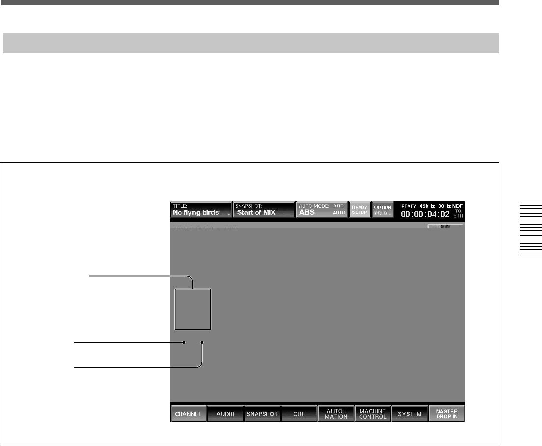
49
Chapter 3 Menu
Chapter 3 Menu
AUX SEND Window
To open this window, touch the CHANNEL button on
the bottom menu bar, then select “AUX SEND.” Or,
when the CHANNEL window is displayed, touch any
point on the AUX SEND display. This window allows
you to display and control the settings for AUX SEND
1 to 8.
The ON button and PRE button on the window have
the same function as those of the AUX SEND section
on the Parameter Setting panel.
By touching the display window where the numerical
values are displayed, these items are switched to
READY or DROP IN/OUT of automation WRITE.
In stereo mode, the even
channels indicate the panning
setting.
2 ON button
3 PRE button
1 Display window
1 Display window
Displays the levels of the AUX SEND 1 to 8 busses.
The level of the AUX send bus is adjusted using AUX
SEND controls 1 to 8 on the AUX SEND section on
the Parameter Setting panel.
When the AUX send bus is set to stereo mode, the
display windows of the even channels indicate the
panning/balance settings.
To set the AUX SEND bus to stereo mode, select the
MASTER button on the PAGES section and then
access one of the AUX SEND faders. On the display,
select STEREO using the channel mode select button
on the CHANNEL window.
2 ON buttons 1 to 8
Touch the desired button to light it up. The accessed
channel is sent to the corresponding AUX send bus.
For busses set in stereo mode, the pairing of the odd
and even channel is 1 and 2, 3 and 4, 5 and 6, and 7
and 8.
3 PRE (prefader) buttons 1 to 8
Touch the desired button to light it up. The pre-fader
signal of the channel is routed. When the button is
routed, the post-fader signal is sent out.
For buses set in stereo mode, the odd and even
channels are linked, the PRE button of the even
channel toggles the pan on and off.
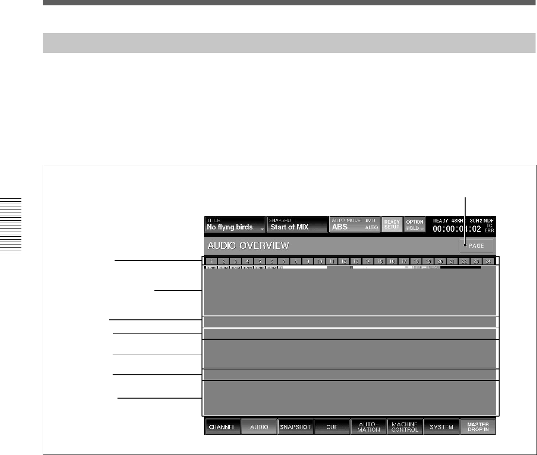
50
Chapter 3 Menu
Chapter 3 Menu
AUDIO OVERVIEW Window
To open this window, touch the AUDIO button on the
bottom menu bar, then select “OVERVIEW”.
This window allows you to see the settings performed
on the unit at glance.
To change channels from the page for CH 1 to CH 24
to the page for CH 25 to CH 48, touch the PAGE
button on the window.
This window shows the active/inactive status of the
equalizer, dynamics, MTR routing and AUX SEND
routing.
When you touch the display, the window of the
corresponding channel (where detailed settings of the
touched item is displayed) appears.
7 PAGE button
1 Input/Assignment display
2 EQ display
3 DYN display
4 AUX display
5 PAN display
6 Fader display
Channel number
1 Input/Assignment display
Displays the following items:
•TRIM: Trim ON/OFF
•DELAY: Delay ON/OFF
•PGM: Status of assignment to the program buses L
and R
•MTR: Status of assignment to the MTR bus
2 EQ display
Displays whether the equalizer/filter circuit is in or
out.
3 DYN display
Displays whether the dynamics circuit is in or out.
4 AUX display
Displays the AUX send level.
5 PAN display
Displays the pan position. When PAN is off, this is
displayed in gray.
6 Fader display
Displays the fader level.
7 PAGE button
Changes the channel page to be displayed on the
AUDIO OVERVIEW window.
Menu Windows
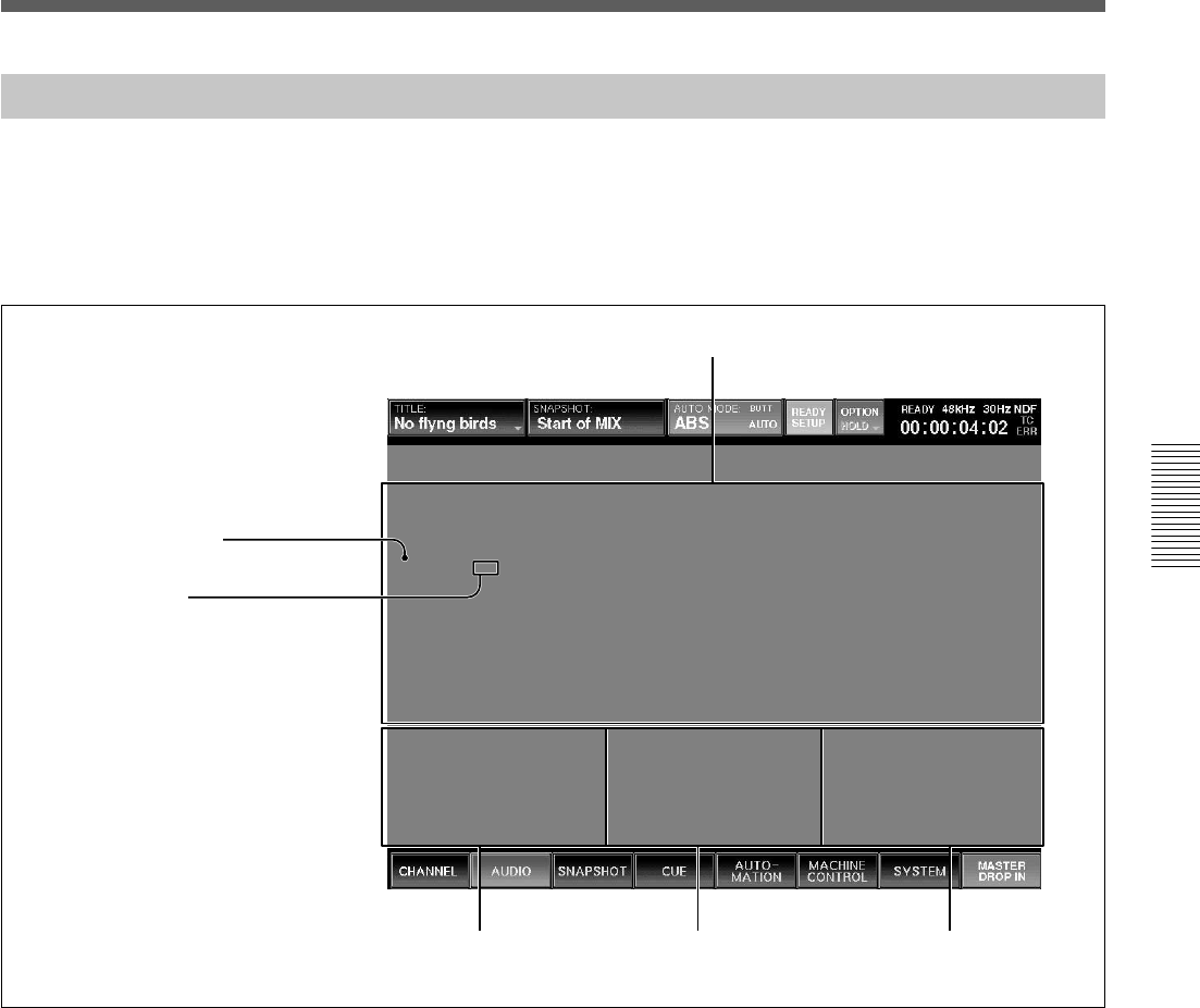
51
Chapter 3 Menu
Chapter 3 Menu
AUDIO FADER Window
To open this window, touch the AUDIO button on the
bottom menu bar, then select “FADER.”
This window allows you to see the fader levels of
channels 1 to 48, the MTR busses, the AUX send
busses and the AUX return busses.
Touching the display of the desired channel opens the
CHANNEL window of the corresponding channel.
Channels 1 to 48
MTR busses 1 to 8 AUX send busses 1 to 8 AUX return busses 1 to 8
1 Fader operation level
1 Fader operation level
The position of the knob indicates the level of the
fader currently set on the unit.
2 Automation level
The position of the horizontal line indicates the level
stored in the automation data.
2 Automation level
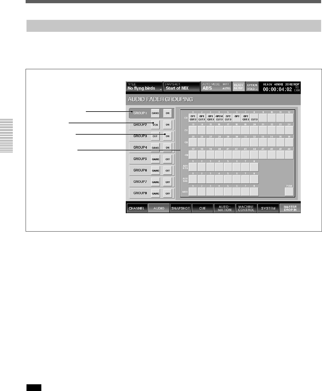
52
Chapter 3 Menu
Chapter 3 Menu
AUDIO FADER GROUPING Window
To open this window, touch the AUDIO button on the
bottom menu bar, then select “FADER GROUPING.”
This window allows you to set the fader group and cut
group for channels 1 to 48, the MTR busses, the AUX
send busses and the AUX return busses.
2 Mode button
1 Group selection area
3 ON/OFF button
4 Channel buttons
1 Group selection area
Touch the corresponding button to select the desired
group.
2 Mode button
Each time you touch this button, the button display
changes to GANG, VCA, or CUT, in order.
GANG: Keeps the relative level among faders when
touching faders on the unit.
VCA: When moving the fader assigned as the master
fader, the difference between the original level and the
current level is added to the level of the slave fader as
offset. Slave faders don’t move when the master fader
is moved.
CUT: The cut switches of the channels belonging to
the corresponding group operate together.
The cut group is set independently from the fader
group.
Note
To select the mode of the group, remove all channels
from the group before attempting to select the mode.
3 ON/OFF button
Selects whether the corresponding group is active.
4 Channel buttons
One channel can belong to one fader group and one cut
group. Channels cannot belong to multiple fader
groups or cut groups.
On the channel button, the upper number indicates the
fader group number and the lower number indicates the
cut group number.
Menu Windows
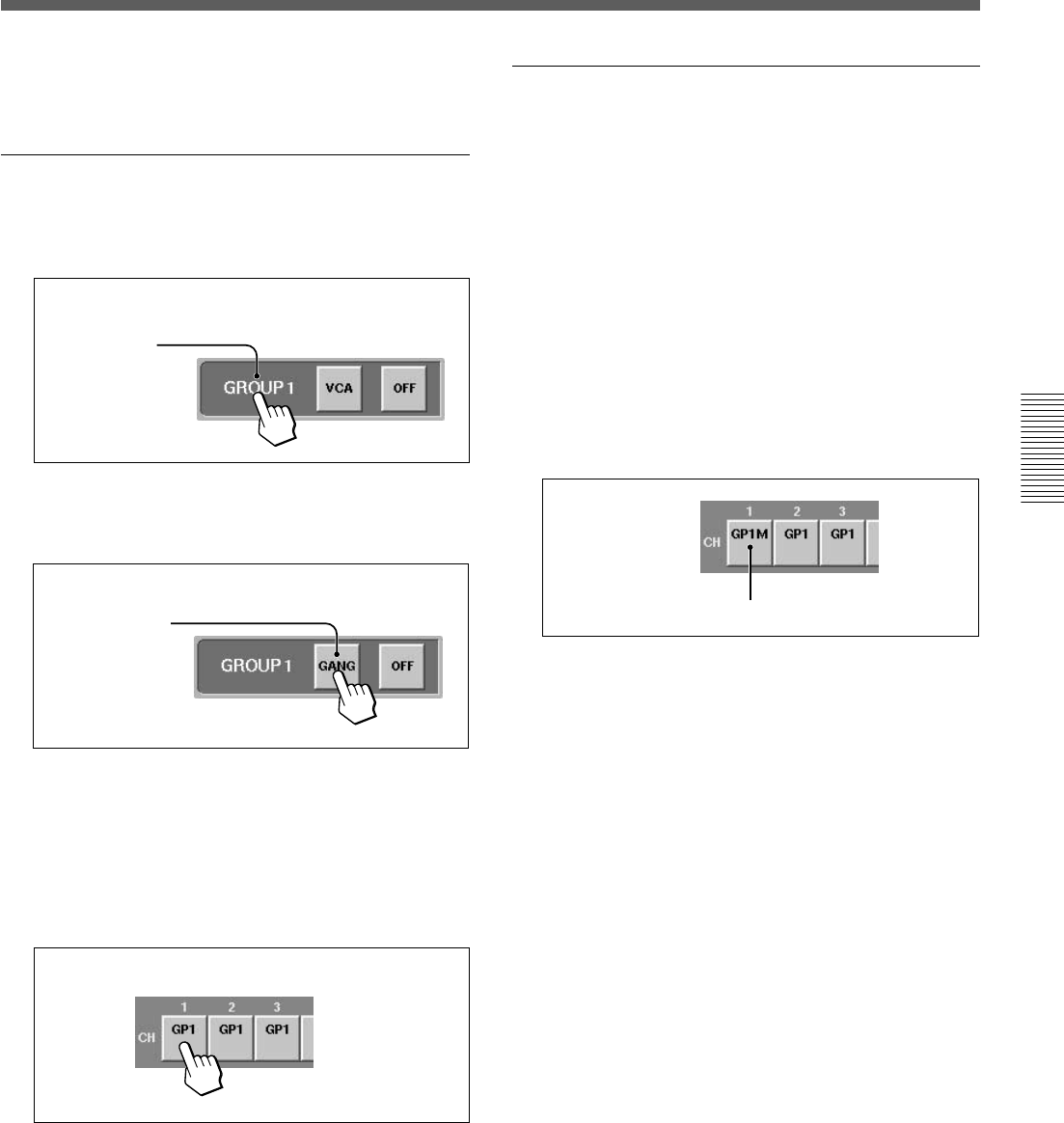
53
Chapter 3 Menu
Chapter 3 Menu
To assign or remove the channel to or from the group,
proceed as follows.
Setting the GANG fader group
1Touch the desired group button.
Example: To set GP 1 to the GANG mode:
Touch the
GROUP 1
button.
2Touch the mode button for the group selected in
step 1 until GANG appears on the mode button.
Display GANG.
3Touch the channel button(s) that you wish to
assign to the GANG group.
Channel(s) already assigned to other GANG or
VCA groups must be unassigned before being
available for selection.
The group number appears on the channel button.
GP1 appears.
To remove the channel from the group, touch this
button(s) on which the group number is displayed.
The group number disappears and that channel is
removed from the group.
Setting the VCA fader group
Perform the following operation after step 1 described
in “Setting the GANG fader group”.
2Touch the mode button corresponding to the group
selected in step 1 until VCA appears on the mode
button.
3Touch the channel button that you wish to assign
to the VCA group.
When there are channels that are not assigned to
the group, the fader of the channel that you
touched first becomes the master fader. GP1M is
displayed on the channel button assigned to the
master fader.
GP1M (Master fader of the VCA group 1)
To remove the channel(s) from the group, touch
this button(s) on which the group number is
displayed.
In the VCA group, if you touch the channel button
assigned to the master fader, the master fader
becomes a slave fader of the group, and the group
has no master fader. The fader which you touch
first after removing the former master fader
becomes the new master fader of the group.
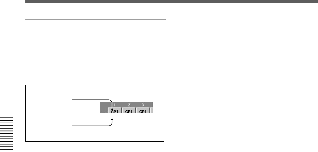
54
Chapter 3 Menu
Chapter 3 Menu
Setting the CUT group
You can set the CUT group with the same operation
procedure as the ones for setting the GANG group
except that you have to display CUT on the mode
button in step 2.
The cut group number is displayed on the lower part of
the channel button.
Fader group number
Cut group number
Clearing the group
1Touch the group button corresponding to the
group that you wish to clear.
2Touch all channel buttons assigned to the group
selected in step 1.
Menu Windows
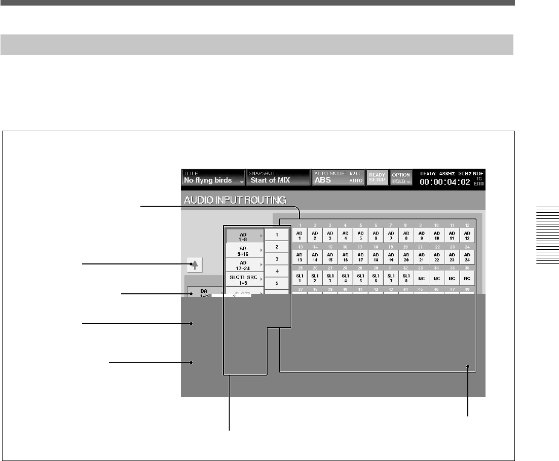
55
Chapter 3 Menu
Chapter 3 Menu
AUDIO INPUT ROUTING Window
To open this window, touch the AUDIO button on the
bottom menu bar, then select “INPUT ROUTING.”
This window allows you to assign the desired input
signal to the desired channel.
2 V button
2 v button
Block list
TB IN button
1 Destination select buttons
3 Source select button
4 DEFAULT button
1 Destination select buttons (CH-1 to CH-48, AUX
RET 1 to 8, INS RET 1 to 8, EXT MONI 1 to 6, TB
IN)
The large display area shows all of the available
destinations for the input matrix. Once an input signal
has been selected, routing is achieved by pressing the
appropriate destination button.
The talkback microphone can also be routed.
By selecting the TB IN button, the input signal selected
by the source select button is used as the talkback
signal. For example, if you assign LINE IN CH24 to
the TB IN button, the input of the LINE IN CH 24 can
be used as the talkback signal.
2 v/V buttons
Touch the V button to select the block over the
currently selected block.
Touch the v button to select the block below the
selected block.
3 Source select button
Displays the selected source block.
Touch this button to open the block list in the B
direction. Touch the desired block button to open the
list of the sources included in the block.
The list of source blocks and the source list of each
source block are as follows:
•Blocks for AD 1 to 8 to AD 17 to 24
Each block has the source lists for 8 inputs.
•Blocks for SLOT 1 to SLOT 4
Each block has the source lists for 8 channels.
•AUX RET block
This block has the source list for 8 channels.
•MISC block
Includes the lists of 2TR1-L, 2TR1-R, 2TR2-L,
2TR2-R, NC (NO CONNECTION) and TB MIC.

56
Chapter 3 Menu
Chapter 3 Menu
The display of the block list buttons corresponding to
SLOT 1 to SLOT 4 depends on the board inserted.
•When the DMBK-R101 is inserted: SLOTxADC1 to
8
•When the DMBK-R102 is inserted: SLOTxDAC1 to
8
•When the DMBK-R103 is inserted: SLOTxDIO1 to
8
•When the DMBK-R104 is inserted: SLOTxSRC1 to
8
•When the DMBK-R105 is inserted:
SLOTxINSERT1 to 8
•When the DMBK-R106 is inserted: SLOTxADAT1
to 8
•When the DMBK-R107 is inserted: SLOTxTDIF1 to
8
4 DEFAULT button
Touch this button to reset the setting of the input
matrix to the default.
Assigning the input source
1Touch the source select button.
The block list opens.
2Touch the desired source block on the block list.
The list of the sources included in the block opens.
If you want to assign all 8 sources to 8 adjacent
processing channels, go to step 4.
3Touch the desired source on the source list.
4Touch the desired destination select button to
select the destination processing channel to which
the source signal is to be routed.
The source signal selected in step 3 is
automatically routed to the destination processing
channel. When you want to assign a complete
block, simply select the block as is in step 2, then
touch the first destination processing channel.
Example: When you select ANALOG IN 1 to 8 as
a block, if you touch this button of CH-3, the
source signals of ANALOG IN 1 to 8 are routed to
CH-3 to CH-10 respectively.
Resetting the input matrix to the default
setting
1Touch the DEFAULT button.
A dialog box appears.
2Touch [OK] in the dialog box.
The setting of the input matrix is reset to the
default setting.
For detailed information on the contents of the default
setting, see page 90.
Menu Windows
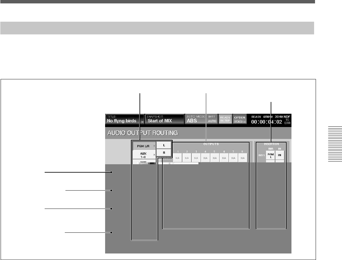
57
Chapter 3 Menu
Chapter 3 Menu
AUDIO OUTPUT ROUTING Window
To open this window, touch the AUDIO button on the
bottom menu bar, then select “OUTPUT ROUTING”.
This window allows you to assign the bus output
signal to the desired output connector.
2 V button
2 v button
4 Output connector select buttons
5 INSERTION buttons
Block list
1 Bus select button
Displays the block (or bus) currently selected.
Touch this button to open the list for the bus output
blocks in the B direction. Touch the desired bus block
to open the list of the busses included in the block.
The list of the block and its output bus list are as
follows:
•PGM L/R
L and R
•AUX
This block has 8 buses (AUX 1 to 8).
•MTR
This block has 8 buses (MTR 1 to 8).
•INS SEND
This block has 8 buses (Insert Send 1 to 8).
•DIRECT OUT 1 to 8 to 41 to 48
Each block has 8 outputs.
1 Bus select button
3 DEFAULT button
•MSC
This block has NC (NO CONNECTION), CR
MONITOR 1 to 6 and ST MONITOR L/R.
2 v/V buttons
Touch the V button to select the block above the
selected block.
Touch the v button to select the block below the
selected block.
3 DEFAULT button
Touch this button to reset the setting of the output
matrix to the default.

58
Chapter 3 Menu
Chapter 3 Menu
4 Output connector select buttons
SLOT 1 to 4, AUX SEND 1 to 8, PGM, MONI OUT
Selects the output connector to which the bus block is
routed.
Each of SLOT 1 to SLOT 4 has 8 output connectors.
5 INSERTION buttons
BUS buttons: Assigning an insert to an output bus is a
2 stage process. Firstly the output buses are assigned to
internal INSERTION circuits (assigned by selecting
each mono output bus from the block list and then
touching the selected INSERTION button), second
each insertion must be assigned to an output and an
input on the two routing pages.
IN button: When IN is displayed on the button by
touching it, the bus insert is active.
When OUT is displayed on the button, the insertion
send signal is still outputted. However, the insertion
return signal is not used.
Note
These inserts can be only assigned to bus signals
(PGM, AUX SEND and MTR buses).
Assigning the bus
1Touch the bus select button.
The block list of the bus opens.
2Touch the desired bus on the block list.
The list of the busses included in the selected block
opens.
To select the busses by the block, go to step 4.
3Touch the desired bus on the bus list.
4Touch the output connector button to route the bus
signal.
The bus signal selected in step 3 is routed to the
output terminal selected in step 4.
You can route entire output block to an adjacent
set of output connectors by simply selecting the
block and then touching the first output connector
button.
Example: When you select MTR 1 to 8 as a block,
if you touch this button of SLOT 1, the bus signals
of MTR 1 to 8 are routed to SLOT 1 to SLOT 8
respectively.
Resetting the output matrix to the default
setting
1Touch the DEFAULT button.
A dialog box appears.
2Touch [OK] in the dialog box.
The setting of the output matrix is reset to the
default setting.
For detailed information on the contents of the default
setting, see page 90.
Menu Windows
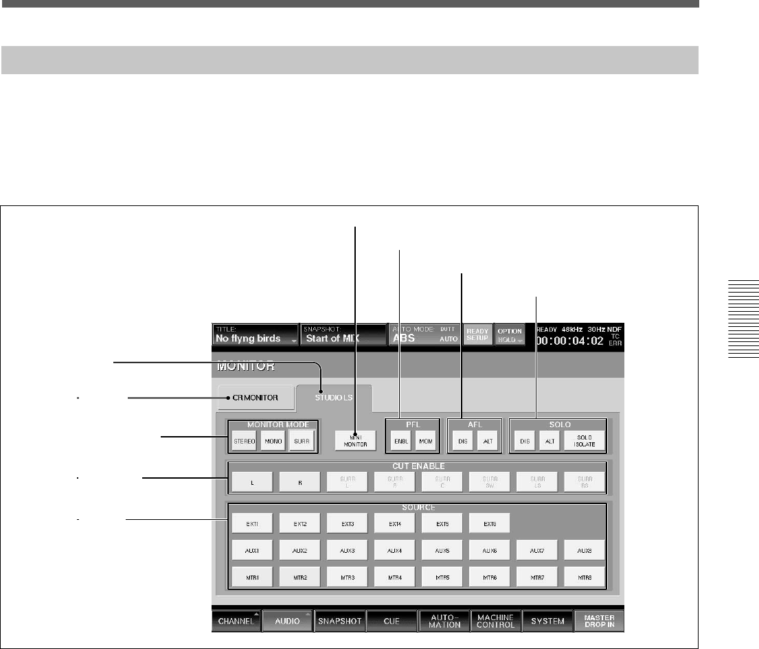
59
Chapter 3 Menu
Chapter 3 Menu
MONITOR Window
To open this window, perform one of the following:
•Touch the AUDIO button on the bottom menu bar,
then select “MONITOR.”
•Press the SETUP button on the STUDIO LS section
or the CR MONITOR section of the front panel.
This window allows you to control and check the
settings for monitoring.
1 STUDIO LS (studio monitor) tab
Touch this tab to switch the display to the studio
monitor section.
2 CR MONITOR (control monitor) tab
Touch this tab to switch the display to the control
room monitor section.
3 MONITOR MODE buttons
Select the mode for the audio monitoring.
STEREO button: Touch this button to select the
stereo mode.
The L signal (or the odd channel) is outputted directly
to the L channel of the monitor and the R signal (or
the even channel) is outputted directly to the R
channel of the monitor.
MONO button: Touch this button to select the
monaural mode.
The L + R signal is outputted to both the L and the R
channels of the monitor.
SURR (surround) button: Touch this button to select
the surround mode. The signal of MTR 1 to 6 or EXT
1 to 6 is sent to CR MONI 1 to 6 as the surround
signal. This button is active only for CR MONITOR
and you can turn it on and off regardless of the settings
of the STEREO and MONO buttons.
6 MINI MONITOR button
7 PFL buttons
8 AFL buttons
9 SOLO buttons
1 STUDIO LS tab
2 CR MONITOR tab
3 MONITOR MODE buttons
4 CUT ENABLE buttons
5 SOURCE buttons

60
Chapter 3 Menu
Chapter 3 Menu
4 CUT ENABLE buttons
When the CUT button on the CR MONITOR section
is lit, you can cut the monitor signal by touching the
desired CUT buttons, L, R, SURR L to SURR RS on
the window.
The SURROUND L, C, SW, R. LS and PS buttons are
active only in the surround mode.
Note
If the CUT ENABLE button is set to OFF, even if you
press the CUT button on the CR MONITOR section so
that it is lit, the audio signal cannot be cut.
For detailed information on the CR MONITOR section, see
page 24.
5 SOURCE buttons
These are used to select the signals for control room
monitoring. Touch the CR MONITOR tab, then select
the desired source for each EXT, AUX, MTR button
on the SOURCE section of the Control room section,
by touching the corresponding SOURCE buttons.
For the STUDIO LS monitoring, touch the STUDIO
LS tab. You can monitor the source selected on the
SOURCE buttons.
EXT 1 to EXT 6 buttons: The input routing matrix
allows you to assign any input signal to the EXT 1 to 6
channels. When you touch EXT 1 to 6 buttons, you
can monitor the signals using the EXT button on the
SOURCE section.
When the SURR button is set to ON, you can monitor
the signals of EXT 1 to EXT 6.
When the SURR button is set to OFF, you can select
one pair among pairs of 1/2, 3/4, and 5/6. It is possible
to set both buttons to ON in one pair.
For example, When the EXT 1 button is ON and the
EXT 2 is OFF, by touching either the EXT 1 or EXT
2, a pair of EXT 1/2 is selected.
When EXT 1 and EXT 2 buttons are ON and the EXT
6 button is OFF, by touching the EXT 6 button, the
pair of EXT 5 and EXT 6 is selected.
In the CR MONITOR section, you can monitor the
selected source signals when the EXT button in the
SOURCE section of the Control room section is
selected.
In the STUDIO LS section, you can monitor the
selected source signal by selecting the EXT 1 to 6
button and pressing the SETUP button on the front
panel.
AUX 1 to AUX 8 buttons: These buttons allow you
to monitor the AUX SEND buses and they operate
like the EXT 1 to 6 buttons.
In the CR MONITOR section, you can monitor the
signals when the AUX button in the SOURCE section
of the Control room section is selected.
In the STUDIO LS section, you can monitor the signal
when the SETUP button is selected in the STUDIO LS
section on the Master panel.
MTR 1 to MTR 8 buttons: When the SURR button is
set to ON, you can monitor the surround sound
mixer’s output from the MTR buses 1 to 6. MTR 7
and MTR 8 become one pair. You can select either
MTR 1 to MTR 6 or a pair of MTR 7 and MTR 8. In
this case, by selecting either MTR 7 or MTR 8, select
the pair.
When the SURR button is set to OFF, these buses are
selected by pairs of 2 channels as in the case of the
EXT buttons.
In the CR MONITOR section, you can monitor the
signals when the MTR button in the SOURCE section
of the Control room section is selected.
In the STUDIO LS section, you can monitor the signal
when the SETUP button is selected in the STUDIO LS
section on the Master panel.
PGM button: L and R monitored by selecting the
PGM button in the CR and STUDIO LS sections.
6 MINI MONITOR buttons
When the SURR button is set to OFF, you can change
the output bus of the CR monitor from CR 1/2 to CR
5/6. This button is not active when the SURR button is
set to ON.
7 PFL buttons
Select how the PFL signal and AFL signal are injected
into the monitoring.
Menu Windows
A ENBL/DIS button B ALT/MOM button
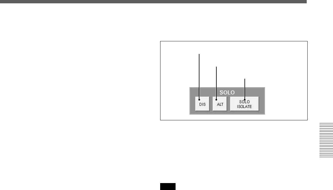
61
Chapter 3 Menu
Chapter 3 Menu
A ENBL/DIS (enable/disable) button
This button enables (or disables) the PFL monitor
logic to inject the signal into the control room or
studio LS output. It is possible to configure the mixer
so that studio LS can be used as a dedicated PFL
output.
When ENBL is displayed, the PFL signal is inserted
into the monitor signal.
When DIS is displayed, the PFL signal is not inserted
into the monitor signal.
B ALT/MOM (alternate/momentary) button
This button works for both the studio and the control
monitor signals.
Selects the operation of the SOLO button of each
channel when PFL is set to SOLO mode.
When MOM (MOMENTARY) is displayed, the PFL
signal is active only while you hold down a channel
SOLO button.
When ALT is displayed, the SOLO buttons operate in
a latching mode.
8 AFL buttons
Select how to insert the AFL signal and SOLO signal
into the monitor signal.
A ENBL/DIS (enable/disable) button
When ENBL is displayed, the AFL signal is inserted
into the monitor signal.
When DIS is displayed, the AFL signal is not inserted
into the monitor signal.
B ALT/MOM (alternate/momentary) button
This button works for studio monitor signals and select
the operation of the SOLO button when the mixer is
set to SOLO mode.
When MOM (MOMENTARY) is displayed, the AFL
signal is inserted only while you hold down the SOLO
button on the unit.
When ALT is displayed, the AFL signal is toggled off
and on each time you press the SOLO button.
9 SOLO buttons
Set the functions of SOLO.
AENBL/DIS button
BALT/MOM
button
CSOLO ISOLATE
button
A ENBL/DIS (enable/disable) button
Selects whether the SOLO function is executed or not.
When ENBL is displayed, the SOLO function is
executed.
When DIS is displayed, the execution of the SOLO
function is prohibited.
Note
In DMX-R100, the SOLO mode is the listening mode
which cuts all other channels. So SOLO affects the
monitor and other mixer outputs. The AFL and PFL
are the non-destructive listening modes that do not
affect the other mixer outputs.
This button works for both the studio and the control
monitor signals, differentiating from AFL and PFL.
B ALT/MOM (alternate/momentary) button
This button works for both studio and control monitor
signals.
Selects the operation of the SOLO button of each
channel when setting the SOLO mode to SOLO.
When MOM is displayed, the SOLO signal is inserted
only while you hold down the SOLO button on the
unit.
When ALT is displayed, the SOLO signal is toggled
off and on each time you press the SOLO button.
C SOLO ISOLATE button
SOLO ISOLATE allows you to protect mixer channels
from being CUT when the SOLO button is pressed on
another channel. The SOLO ISOLATE is often used
on channels that process signals from external effects
devices.
To set a channel to SOLO ISOLATE, touch the SOLO
ISOLATE button on the display and then press the
channel SOLO buttons for the desired channels.
Switching the SOLO ISOLATE display but clears the
isolated channels.
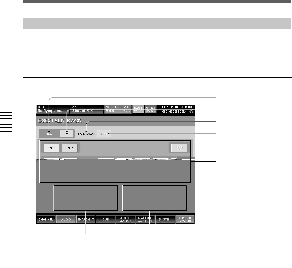
62
Chapter 3 Menu
Chapter 3 Menu
Menu Windows
OSC/TALKBACK Window
To open this window, perform one of the following:
•Touch the AUDIO button on the bottom menu bar,
then select “OSC/TALKBACK”.
•Press the SETUP button on the Talkback panel on
the unit.
This window allows you to operate oscillators and
talkback functions.
1 OSC tab
2 ON button
3 TALKBACK tab
4 MEMORY button
5 Output select buttons
6 FREQUENCY SET
buttons/GANG button/
display window
7 LEVEL SET buttons/GANG
button/display window
1 OSC (oscillator) tab
Touch this tab to set up the oscillators.
3 TALKBACK tab
Touch this tab to set up the settings for talkback
system.
When selecting the OSC tab
When the OSC tab 1 is selected, buttons 2 and 5
act as setting buttons for oscillators.
2 ON (Oscillator signal output ON/OFF) button
When the button is ON, the oscillator signal is sent to
the signal path. Select the signal path for the oscillator
signal output using the Output select buttons 5.
When the button is OFF, the oscillator signal is not
outputted.

63
Chapter 3 Menu
Chapter 3 Menu
5 Output select buttons
Touch the corresponding button to select the desired
signal path for the oscillator signal.
6 FREQUENCY SET buttons/GANG button/
display window
L SET/R SET buttons: Touch the SET button so that
you can set the frequency of the L or R oscillator
signal using the jog dial on the unit. The set frequency
is displayed on the display window.
GANG button: Touch the GANG button so that you
can adjust the frequency of the L and R oscillator
signals in gang mode.
7 LEVEL SET buttons/GANG button/display
window
L SET/R SET buttons: Touch the SET button so that
you can set the level of the L or R oscillator signal
using the jog dial on the unit. The set level is displayed
on the display window.
GANG button: Touch the GANG button so that you
can adjust the level of the L and R oscillator signals in
gang mode.
When selecting the TALKBACK tab
When the TALKBACK tab 3 is selected, buttons 4
and 5 act as control buttons for talkback signals.
Buttons 6 are not effective.
4 MEMORY button
When the MEMORY button is on, the active/inactive
status of the talkback output select buttons 5 are
stored. The buttons on the TALKBACK panel are then
enabled to activate talkback to PGM, AUX SEND and
MTR buses.
When the MEMORY button is off, the talkback signal
of the built-in microphone is sent to the bus selected
on the Talkback panel while holding down the
corresponding output select button 5.
5 Output select buttons
Touch the desired output select button so that the
talkback signal is sent to the bus or connector selected
by the output select button.
7 LEVEL SET buttons/GANG button/display
window
Touch the R LEVEL SET button to adjust the level of
the talkback signal using the jog dial on the unit.
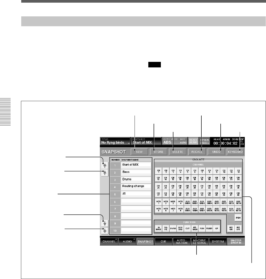
64
Chapter 3 Menu
Chapter 3 Menu
Menu Windows
SNAPSHOT Window
To open this window, perform one of the following:
•Touch the SNAPSHOT button on the bottom menu
bar.
•Press the SETUP button from among SNAPSHOT
buttons on the Automation panel.
This window allows you to control and monitor the
snapshot automation.
For detailed information on snapshot automation, see page
94.
Note
When you switch on/off of the prefader signal of AUX
SEND or switch pre/post signal of DYNAMICS from
snapshot recall, the output signal may momentarily
switch to the unity gain level.
4 NEW button
5 STORE button
6 DELETE
button
7 RECALL button
8 UNDO button
9 KEYBOARD button
0 FUNCTION buttons
qa ISOLATE CHANNEL buttons
1 Page select button
2 Row select button
3 Snapshot list
1 Page select button
2 Row select button
1 Page select button
Touch to move the snapshot list 3 upwards or
downwards by 10 rows.
2 Row select buttons
Touch to move the snapshot list 3 upwards or
downwards one row at a time.
3 Snapshot list
Displays the number and name of the stored
snapshots.
You can enter a name for the snapshot data by using
the keyboard connected to the unit or from the
KEYBOARD window.
To select a snapshot, touch its number or name in the
list.

65
Chapter 3 Menu
Chapter 3 Menu
4 NEW button
Touch this button to store the current mixer settings as
a new snapshot data.
The lowest unused number is used for the new
snapshot and it is temporarily named “# + xx” (xx is
the snapshot number).
5 STORE button
Touch this button to store the current mixer setting to
the snapshot data selected on the snapshot list 3.
6 DELETE button
Touch this button to delete the snapshot selected on
the snapshot list 3.
7 RECALL button
Touch this button to recall the snapshot selected from
the snapshot list 3.
8 UNDO button
Touch this button to cancel the previous snapshot
operation.
9 KEYBOARD button
Touch this button to open the KEYBOARD window.
This KEYBOARD window allows you to enter or
change the name of a snapshot.
0 FUNCTION (local) buttons
When you touch the FUNCTION button, the
corresponding function is not recalled when the
SNAPSHOT RECALL is perfomred. Other functions
not listed beloware recalled by snapshot on
independently of the FUNCTION LOCAL button
settings.
•IN ROUT button removes the INPUT ROUTER, ∅,
TRIM, DELAY functions.
•EQ/FIL button removes the equalizer and filter
functions.
•DYNA button removes the dynamics functions.
•AUX SND button removes the aux send functions.
•CUT button removes the cut functions.
•ASSIGN button removes the assign functions.
•PAN button removes the panning and surround
panning functions.
•FADER button removes the fader and MTR send
functions.
•GP button removes the fader group settings.
The FUNCTION (local) buttons only affect
SNAPSHOT RECALL. All of the mixer’s processing
parameters are saved, regardless of the FUNCTION
button status.
qa ISOLATE CHANNEL buttons
CH 1 to PGM buttons: Touch the button
corresponding to the channel that you want to remove
SNAPSHOT RECALL. The ISOLATE CHANNEL
buttons only affect the SNAPSHOT RECALL, and all
of the mixer’s channels are saved in snapshots
regardless of the ISOLATE CHANNEL button status.
ALL ON button: Sets all channels to the ISOLATE
function.
ALL OFF button: Clears the ISOLATE function of
all channels
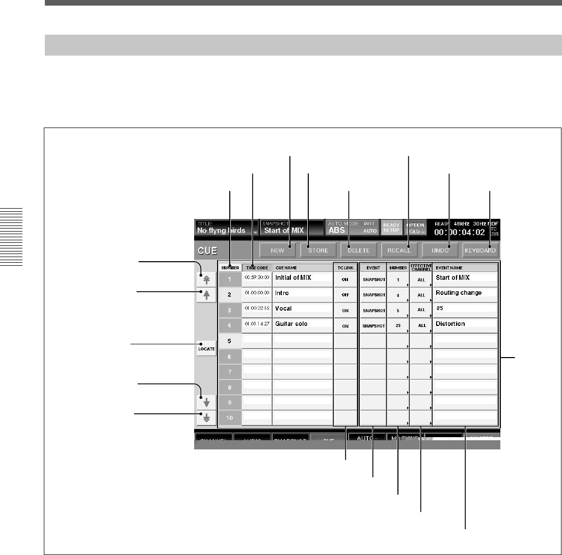
66
Chapter 3 Menu
Chapter 3 Menu
Menu Windows
CUE Window
To open this window, touch the CUE button on the
bottom menu bar. This window allows you to control
the cue function.
For detailed information on cue operation, see page 96.
0 CUE list
qa TC LINK buttons
qd NUMBER buttons
qf EFFECTIVE CHANNEL buttons
qg EVENT NAME display
1 Page select button
2 Row select button
1 Page select button
2 Row select button
1 Page select button
Touch this button to move the CUE list 0 up or down
by 10 rows .
2 Row select button
Touch this button to move the CUE list 0 up or down
one row at a time.
3 LOCATE button
To locate the selected machine to a cue timecode,
select the cue by touching it on the display and then
touch the LOCATE button.
4 NEW button
Touch this button to save a new cue. The timecode
displayed on the display window on the Automation
panel is value for the new cue.
The lowest number among the unused numbers is
assigned to the new cue point and it is temporarily
named “# + xx” (xx is the cue point number). This
new cue point is displayed on the CUE list.
When the TC LINK button is lit on the Automation
panel on the unit, and you touch the NEW button, the
mixer saves a cue and snapshot and it also
automatically links the snapshot to the cue, using the
TC LINK function.
3 LOCATE button
4 NEW button
5 STORE button
6 DELETE button
7 RECALL button
8 UNDO button
9 KEYBOARD button
qs EVENT buttons
NUMBER button
TIMECODE button

67
Chapter 3 Menu
Chapter 3 Menu
Note
Do not recall snapshots linked to continuous cues that
have duration lower than 5 frames each other.
Otherwise, only the snapshot linked with the last cue
may be recalled. Automation data for duration of
remaining cues may not be recalled and saved.
5 STORE button
Touch this button to save a cue. The timecode
displayed on the Automation panel is saved with the
cue.
6 DELETE button
Touch this button to delete the selected cue point from
the CUE list 0.
If the event is linked with the cue point, the event is
not deleted.
7 RECALL button
Touch this button to recall the cue point data selected
on the CUE list 0.
When the event is linked with the cue point, this event
is executed.
8 UNDO button
Touch this button to cancel the previous snapshot
function performed using the SNAPSHOT buttons on
the Automation panel on the unit.
9 KEYBOARD button
Touch this button to open the KEYBOARD window.
This KEYBOARD window allows you to enter or
change the name of the cue point.
0 CUE list
Displays the number, address (timecode) and name of
cue points stored.
NUMBER row: Displays the cue number.
TIMECODE row: Displays the time (timecode) of
the cues.
By touching the timecode box, you can change the
timecode using the ten key pad.
CUE NAME row: By touching a cue name box, you
can enter or change the name of the cue point using the
keyboard connected to the unit or on the KEYBOARD
window.
When you touch the NUMBER button on the top of
the NUMBER row or the TIME CODE button on the
TIMECODE row, the cue list is sorted in the order of
the cue numbers or the timecode.
When the cue list is sorted in the order of the
timecode, the current cue is lit green if any cue point is
not selected.
qa TC LINK buttons
Touch the button to link a SNAPSHOT RECALL to
the specified cue.
qs EVENT buttons
Touch the desired button to open the menu list of the
events that can be TC linked.
SNAPSHOT button: Links a snapshot.
NA (NoACTION) button: Nothing is executed.
qd NUMBER buttons
Touch the desired button to open the event name list
and select the desired event to be executed.
qf EFFECTIVE CHANNEL buttons
Specify the channels which the event affects.
When the ALL button is displayed: Touch this button
to specify all channels.
When the EVENT button qs indicates SNAPSHOT
then only the ALL button is automatically switched to
ALL.
qg EVENT NAME display
Displays the event name.
Initial cue
•CUE 1 is reserved as an initial cue to indicate the
start point of the dynamic automation.
•If automation reference timecode is lower value than
the CUE 1 value, dynamic automation doesn’t
operate.
•To change the initial cue, perform the same
procedure as for changing other cue points. But if
you set the timecode after the timecode of the initial
cue, dynamic automation data between the former
timecode and the newly set timecode will be lost.
Similarly, you can change the snapshot linked with
the initial cue. But if you change it, a problem may
occur between the snapshot data and the automation
data.
For detailed information on cue, see “Cue Operation
Procedure” on page 96.
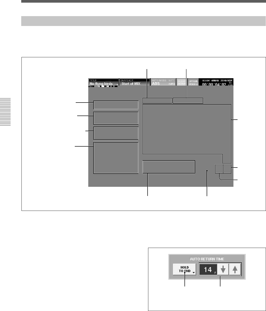
68
Chapter 3 Menu
Chapter 3 Menu
Menu Windows
AUTOMATION Window
To open this window, touch the AUTOMATION
button on the bottom menu bar. This window allows
you to control aspects of the dynamic automation.
5 AUTOMATION ISOLATE tab
1 FREE MEMORY display
2A/B BUFFER ROTATION
section
3 AUTO RETURN TIME section
4 PUNCH IN/OUT section
1 FREE MEMORY display
Displays the remaining amount of memory available
for dynamic automation data storage.
2 A/B BUFFER ROTATION section
Sets the memory buffers for two different modes.
AUTO button: When an automation data is
completed, the active buffer switches automatically
from A to B or B to A.
(When the TC AUTOMATION SAFE button is
selected on the Automation panel, the active buffer is
not switched since automation data can not be
overwritten.)
MANUAL button: The MANUAL mode allow two
separate automation files for the title.
3 AUTO RETURN TIME section
This section allows you to set the mode for control to
return to previous automated positions when the
DROP OUT function is performed.
For detailed information on automation, see page 98.
AAutomation return
mode button
B RAMP frame display
6 MAKE STATIC tab
0 FUNCTION ISOLATE buttons qa MAKE STATIC EXECUTE button
7Channel
buttons
8ALL OFF
button
9ALL ON
button

69
Chapter 3 Menu
Chapter 3 Menu
A Automation return mode button
Touch this button to select the mode that returns to the
previous data.
BUTT: Returns to the previous data quickly after the
DROP OUT.
RAMP: Ramps back to the previous position after the
DROP OUT.
HOLD TO NEXT: Holds the position after the DROP
OUT until the next automation move is replayed.
HOLD TO END: Holds the position after the DROP
OUT.
B RAMP frame display
Sets the time to return to the position stored in the
previous data in unit of frame.
You can set the desired number of frames using the m/
M buttons.
4 PUNCH IN/OUT section
This section allows you to punch in and out of
dynamic automation WRITE by sending the ON/OFF
signal or specifying the timecode.
FOOT SW button: Touch this button to active the
foot switch automation WRITE control. When this
button is not selected, the foot switch status is ignored.
AUTO button: Touch this button to enable the
PUNCH IN TIME/PUNCH OUT TIME display
windows. When this button is not selected, automation
data is stored regardless of the values in the PUNCH
IN/OUT TIME windows.
PUNCH IN TIME button and display window:
Touch this button to accept the time displayed on the
timecode display window on the Automation panel.
This time is then displayed in the windows.
You can enter the timecode using the ten keys by
touching the timecode on the display window.
Remember to press the ENTER button to accept this
value.
You can increase or decrease the numeric values using
the + / - buttons and the jog dial.
PUNCH OUT TIME button and display window:
Touch this button to accept the time displayed on the
timecode display window on the Automation panel.
This time is then displayed in the window.
You can enter the timecode using the ten keys by
touching the timecode on the display window.
Remember to press the ENTER button to accept this
value.
You can increase or decrease the numeric values using
the + / - buttons and the jog dial.
5 AUTOMATION ISOLATE tab
Selects the channels or functions that you want to
isolate from automation replay.
Touch this tab, then touch the CHANNEL button(s)
and FUNCTION button(s) for the functions you want
to isolate.
6 MAKE STATIC tab/qa MAKE STATIC
EXECUTE button
To select the channels whose automation data you
want to delete, touch the MAKE STATIC tab 6, then
touch the desired CHANNEL button(s).
Touching the MAKE STATIC EXECUTE button after
selecting the channel results in clearing all the
automation data from that channel.
7 Channel buttons (CH1 to PGM)
After selecting the AUTOMATION ISOLATE tab 5
(or MAKE STATIC tab 6), select the channel that
you want to isolate from automation replay (or the
channel that you want to delete) using these channel
buttons.
8 ALL OFF button
Touch this button so that no channels are selected.
9 ALL ON button
Touch this button to select all channels.
0 FUNCTION ISOLATE buttons
Touch the button to remove the mixer’s functions from
automation replay. The function corresponding to the
selected button is not loaded when replaying
automation files.
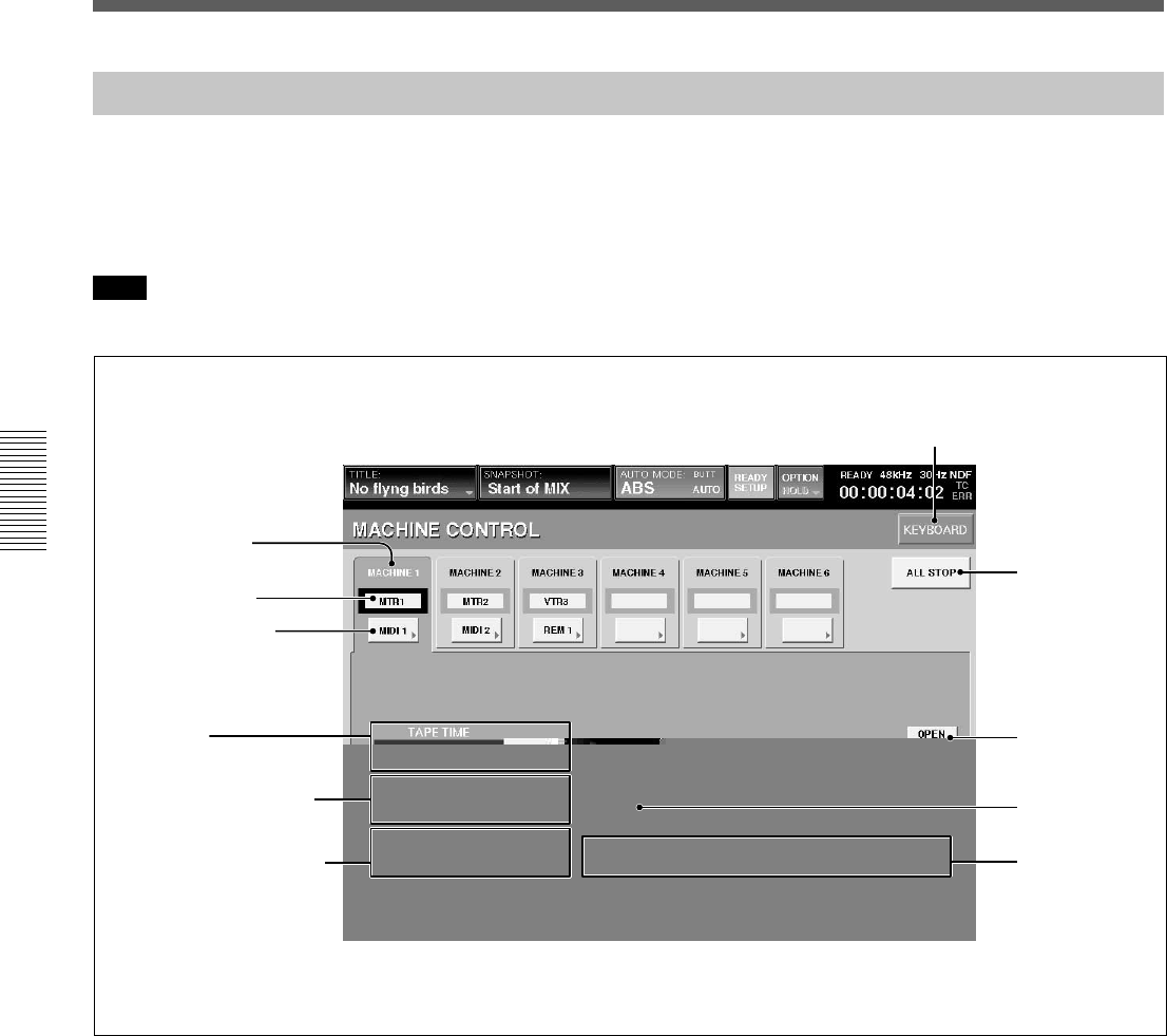
70
Chapter 3 Menu
Chapter 3 Menu
Menu Windows
MACHINE CONTROL Window
3 Port select button
4 TAPE TIME display
window and CAPTURE
button
5 LOCATE TIME display
window and SET button
To open this window, touch the MACHINE
CONTROL button on the bottom menu bar.
This window allows you to set up the mixer to control
devices that use MIDI machine control (MMC), Sony
9-pin and timecode chase.
Note
There may be machines which cannot be controlled
using this unit. Only one machine can be controlled at
any one time, but the mixer can be quickly re-
configured to control up to six different machines.
1 MACHINE tab
Touch this tab to select the machine to be controlled.
You can control the selected machine using the
transport control keys on the unit or from the
MACHINE CONTROL window.
2 Machine name
Displays the name of the machine.
You can change the name of the machine selected by
touching this part, and using the keyboard connected to
the unit or the KEYBOARD window.
3 Port select button
Selects the port assigned to the machine.
•MIDI 1 to 16
•REMOTE OUT 1 or 2
•TC GEN: Built-in timecode generator
•NC (no connection)
4 TAPE TIME display window and CAPTURE
button
Displays the tape time of the machine. Touch the
CAPTURE button to copy the tape time value
displayed on the TAPE TIME display window onto the
LOCATE TIME display.
1 MACHINE tab
2 Machine name
6PREROLL TIME display
window and SET button
7ALL STOP
button
8OPEN LOOP
button
9LOCATE
button
KEYBOARD button
0Transport
control buttons

71
Chapter 3 Menu
Chapter 3 Menu
Note
The tape time may not be displayed depending on the
machines connected.
5 LOCATE TIME display window and SET
button
Displays the time the machine locates when the
LOCATE button 9 is touched.
Touching the SET button allows you to enter the
locate time using the ten key pad.
You can increase or decrease the numeric values using
the + / - buttons and the jog dial.
6 PREROLL TIME display window and SET
button
Sets a preroll time which is used to calculate actual
LOCATE times.
Note
You cannot enter a minus value for the time.
Touching the SET button allows you to enter the
locate time using the ten key pad.
You can increase or decrease the numeric values using
the + / - buttons and the jog dial.
7 ALL STOP button
Touch this button to issue the stop command to all of
the machine control ports.
8 OPEN LOOP button
When MIDI is selected by the Port select button 3,
this button is automatically set to OFF (the button
becomes deactivated) and MIDI must be controlled
using a closed loop (i.e. 2 MIDI cables).
When the return signal is not sent back from the
machine after 2 seconds have elapsed, the unit decides
that it is not possible to exercise control with the
closed loop. In this case, after the dialog is displayed,
the unit changes to open loop control and this button
becomes activated.
Also, you can switch between closed loop control and
open loop control manually.
Note
In OPEN LOOP control, the tape time and the
transport status of the machine can not be displayed.
Also, the transport status may differ from the actual
machine transport.
Open loop control and closed loop control
The open loop control is the one-way control mode
where the command is sent to the machine, but the
return signal is not received from the machine. In the
closed loop mode, the return signal is also received
from the machine. Thus, 2 MIDI cables (one for the
send command and the other is for the return signal)
are required in the closed loop control.
9 LOCATE button
Touch this button to issue the locate command to the
machine at the locate time displayed on the LOCATE
TIME display window.
Notes
•There may be machines that cannot locate even if the
locate command is received.
•The LOCATE button is not effective in the open
loop control.
0 Transport control buttons
Touch the corresponding button to issue the FF, REW,
PLAY, STOP or REC command to the connected
machine.
To set the machine to record mode, touch the REC
button first to make it active, then touch the PLAY
button. Or touch the REC button while playing.
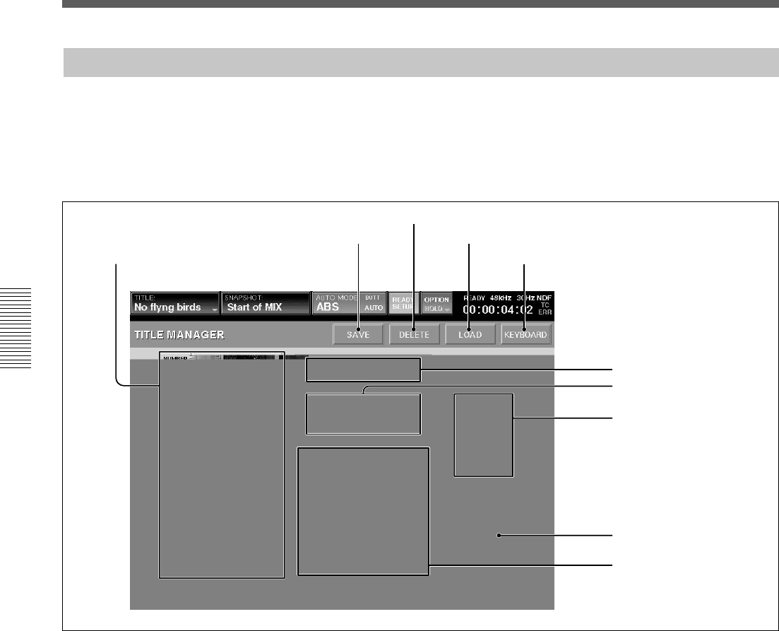
72
Chapter 3 Menu
Chapter 3 Menu
Menu Windows
1 Title list
2 SAVE button
3 DELETE button
4 LOAD button
5 KEYBOARD button
6 FREE SPACE display
7 STORAGE MEDIA buttons
8 FDD OPERATION buttons
9 CURRENT TITLE
CLEAR button
TITLE MANAGER Window
To open this window, touch the SYSTEM button to
open the SYSTEM menu, then select “TITLE
MANAGER.”
This window allows you to create, store and load the
mixer’s titles.
In the DMX-R100, data related to a project (snapshot
data, dynamic automation data, settings for sampling
frequency, timecode mode, etc.) is called “Title.”
There are two types of titles:
•Current title which is the data associated to the
current project.
•Title stored as a file
1 Title list
Displays the list of titles stored in the media selected
by the STORAGE MEDIA button 7.
A maximum of 10 titles can be stored in the flash
memory.This depends on the size of the title.
When you open this window, the title loaded last is
selected.
You can store a minimum one title on one floppy disk.
However, 2 or more floppy disks may be required to
store 1 title depending on the size of the title.
0 INFORMATION section

73
Chapter 3 Menu
Chapter 3 Menu
2 SAVE button
Touch this button to store the current title into the
selected title on the list. Select the media where the
current title is to be saved by the STORAGE MEDIA
buttons 7 before attempting to save.
Notes
•When executing “SAVE” on a floppy disk, the data
previously saved on the disk is cleared.
•After executing “SAVE”, do not turn off the power
while the cursor indication changes to an arrow
showing that the data has been processed or while
the LED on the floppy disk drive in on. If you turn
off the unit during this process, the title being saved
may be lost, as the unit requires time to write the
data in the flash memory or on the floppy disk.
3 DELETE button
Touch this button to delete the title selected on the
title list.
4 LOAD button
Touch this button to load the title selected on the title
list on the unit.
Note
When a title with different Fs setting is loaded, the
unit automatically restarts.
5 KEYBOARD button
Touch this button to open the KEYBOARD window
allowing you to enter the title name or memo.
6 FREE SPACE display
Displays the amount of free space for the media
selected by the STORAGE MEDIA button 7.
When FLOPPY DISK is selected, if the title is saved
on multiple floppy disks, the amount of free space for
each disk is displayed.
7 STORAGE MEDIA buttons
FLASH MEMORY button: Touch this button to
display the titles stored in the built-in flash memory
on the title list.
When the TITLE MANAGER window is opened, the
built-in flash memory is automatically selected.
FLOPPY DISK button: Touch this button to display
the titles stored on the floppy disk.
A dialogue “There are no titles or this an unformatted
disk. Check the media in the floppy disk drive.”
appears, in the following cases:
• A floppy disk is not inserted in the drive.
• The inserted disk is unformatted.
Notes
•When the titles have been saved in the floppy disk,
titles and their information are displayed. When no
title is saved on the floppy disk, the title list section
and INFORMATION section are blank.
•When data has been saved in 2 or more floppy disks
due to the size of the title, #1 or #2 is attached to the
title name displayed in the NAME box in the
INFORMATION section.
•When loading a title of two-disk set, be sure to load
the firs disk (#1 is displayed or blank in the NAME
box in the INFORMATION section). When the
second disk of a two-disk set should be inserted, the
dialog to replace the disk appears.
8 FDD OPERATION buttons
SCAN button: Touch this button so that a floppy disk
is scanned and the titles stored on the disk are
displayed. Be sure to touch this button when you
change the floppy disk.
FORMAT button: Touch this button to format the
floppy disk inserted in the floppy disk drive. All data
stored on the disk is erased. Titles displayed on the
title list disappear.
9 CURRENT TITLE CLEAR button
Touch this button, and a confirmation dialog box
appears. After confirming, the new title is created
based on the current sampling frequency and timecode
mode in the flash memory and is loaded on the unit as
a current title.
The new title is named “UNTITLED”.
Notes
•If a new title is created, all snapshot and automation
data current in the unit are cleared. It is
recommended that you save the data using the SAVE
button 2 before creating a new title.
•When a new title is created by the CURRENT
TITLE CLEAR button, the initial cue is
automatically created. Before using the unit in
automation mode, reset the initial cue data.
For detailed information on the cue operation, see page 96.

74
Chapter 3 Menu
Chapter 3 Menu
Menu Windows
0 INFORMATION section
The following information is displayed for the tile
selected on the title list. You can enter the name and a
memo in those rows.
NAME row: Displays the name of the title. To enter
the title name, touch the NAME row, and then enter
the name using the keyboard connected to the unit or
on the KEYBOARD window.
SIZE row: Displays of the data size of the title.
DATE row: Displays the date when the title was
saved last.
INITIAL CUE row: Displays the timecode of the
initial cue (CUE 1) from which automation starts.
TC MODE row: Displays the mode of the timecode
to be used in automation.
Fs row: Displays the sampling frequency.
MEMO row: Displays the memo attached to the title.
To enter a memo, touch the MEMO row, then enter
the text using a keyboard or on the KEYBOARD
window.
LOCK button: Touch this button to lock the title
selected on the title list. The title is protected from
being overwritten or deleted.
When any title is not selected, the information on the
current title saved last by selecting KEEP on the
TITLE menu.
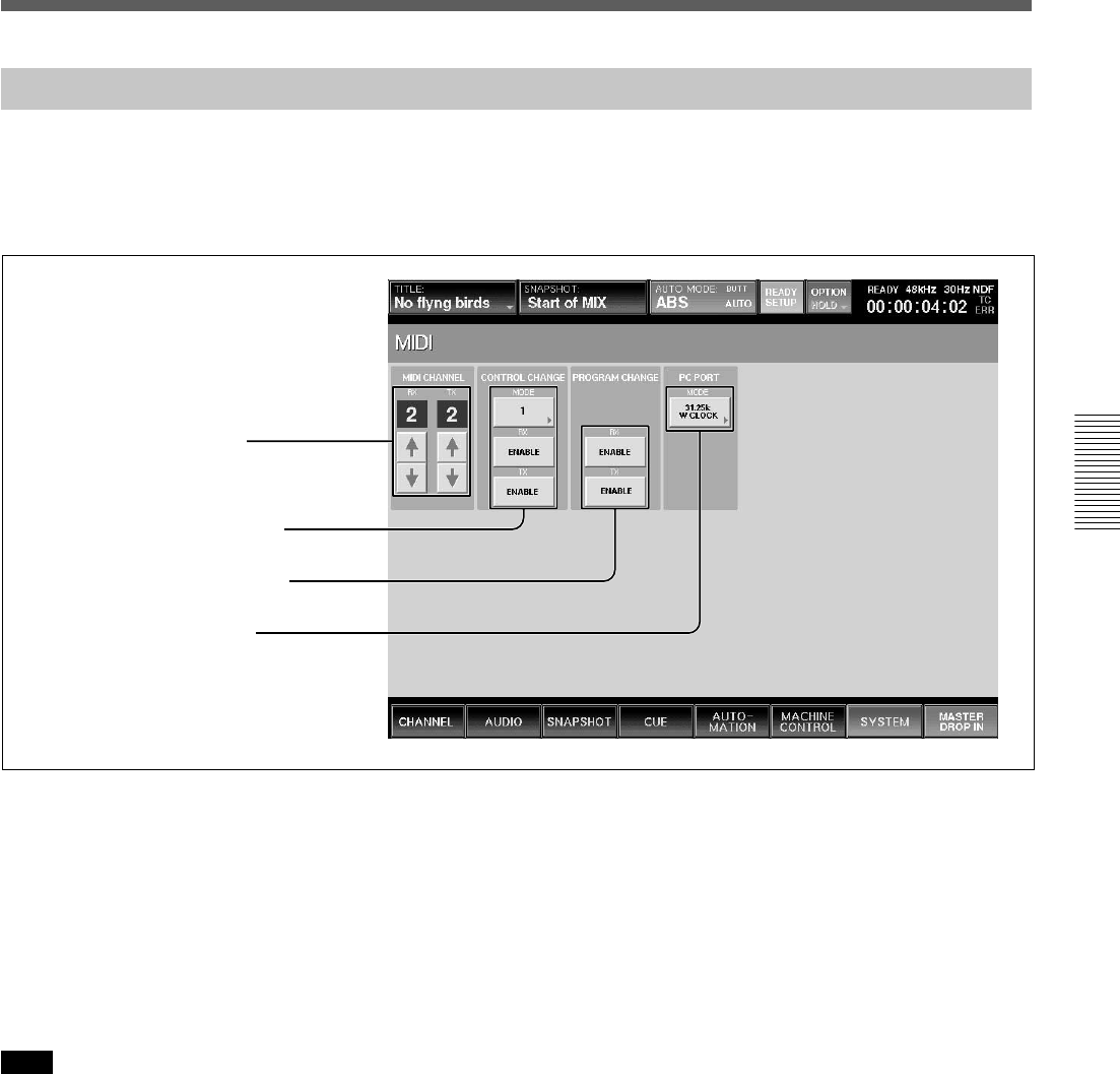
75
Chapter 3 Menu
Chapter 3 Menu
1 MIDI CHANNEL section
2 CONTROL CHANGE section
3 PROGRAM CHANGE section
4 PC PORT MODE section
MIDI Window
To open this window, touch the SYSTEM button on
the bottom menu bar, then select “MIDI” on the menu.
This window allows you to perform the assignment of
the MIDI channels, program change-snapshot
configuration, mixer event-control change
configuration and the settings of the PC ports.
1 MIDI CHANNEL section
RX channel display and channel increment and
decrement buttons: Displays the channel that receives
the MIDI message and executes tasks. Touch the v or
V buttons to select the channel.
TX channel display and channel increment and
decrement buttons: Displays the channel to be used
when transmitting the MIDI message. Touch the v or V
buttons to select the channel.
Note
Usually set the RX channel and TX channel to the same
channel.
2 CONTROL CHANGE section
MODE button: Touch this button to select either
MODE 1 or MODE 2 to set up the configuration of
parameters on the unit and control change message.
For details for each mode, see page 115.
RX ENABLE button: When this button is selected
(ON), the parameters defined in each mode are updated
when receiving the control change message to the
MIDI IN connector.
TX ENABLE button: When this button is selected
(ON), the parameters defined in each mode are sent
from the MIDI OUT connector.
3 PROGRAM CHANGE section
RX ENABLE button: When this button is selected
(ON), the snapshot data is recalled on the unit when
receiving the program change message at the MIDI IN
connector.
TX ENABLE button: When this button is selected
(ON), the snapshot data is recalled and the program
change message corresponding to its program number
is sent from the MIDI OUT connector.
4 PC PORT MODE section
Selects the mode according to the PC connected to the
PC PORT connector.
31.25 k W CLOCK: Selects this mode when a
Macintosh computer is used.
31.25 k, 38.4 kHz: Selects when a PC/AT compatible
computer is used. Select either 31.25 k or 38.4 Kz
according to the external MIDI device.
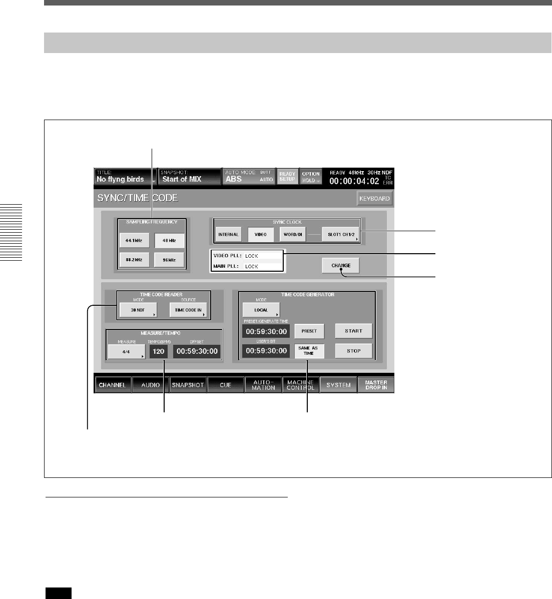
76
Chapter 3 Menu
Chapter 3 Menu
Menu Windows
1 SAMPLING FREQUENCY buttons
2 SYNC CLOCK section
3 PLL status display section
4 CHANGE button
5 TIME CODE READER section
6 MEASURE/TEMPO section 7 TIME CODE GENERATOR section
SYNC/TIME CODE Window
To open this window, touch the SYSTEM button on
the bottom menu bar, then select “TIME CODE” on
the menu.
This window allows you to control the settings of the
reference signal and the timecodes used for
automation.
Synchronous signal section
1 SAMPLING FREQUENCY buttons
Touch the button corresponding to the desired
sampling frequency from 44.1 kHz, 48 kHz, 88.2 kHz
or 96 kHz.
Note
When 88.2 kHz or 96 kHz is selected, the frequency
range expands to 40 kHz. However, the following
functions are limited. Buttons corresponding to the
limited functions are disabled.
•Input channel: The channel number is reduced from
48 to 24.
•AUX Send: The channel number is reduced from 8
to 2.
•AUX Return: The channel number is reduced from 8
to 4.
•MTR bus: The channel number is reduced from 8 to
4.
•Insertion send: The channel number is reduced from
8 to 4.
•Direct out: The channel number is reduced from 48
to 24.
•Optional boards: DMBK-R106 and DMBK-R107
cannot be used.
The DMBK-R104 cannot be used for a channel
where the sample rate converter is set to ON.
•Surround mode is not available.
•The number of oscillator paths becomes one and the
same signal is outputted to both the L and R
channels.
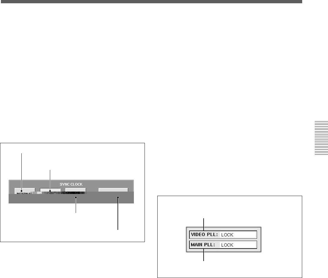
77
Chapter 3 Menu
Chapter 3 Menu
A INTERNAL button
B VIDEO button
C WORD/DI button
D Word clock selector
A VIDEO PLL status
B MAIN PLL status
•The maximum value of the programmable delay
amount is half.
•The channel number of the EXT inputs of
MONITOR is reduced from 6 to 2.
•When INPUT is selected in the CHANNEL
METERS section in the MISC SETUP window, the
OVER indicator does not function.
•The SOLO buttons of the AUX Return function as
AFL buttons even if these are set to PFL.
•When SYNC LOCK is set to WORD/DI, if the sync
reference signal is greater than 96 kHz, the DSP
(Digital Signal Processor) does not work properly
and this may cause noise.
2 SYNC CLOCK section
The unit synchronizes using the reference selected by
touching one of these buttons.
A INTERNAL button
Touch this button to use the built-in word clock
generator as the reference signal.
When this button is selected, external digital audio
equipment must be synchronized with the DMX-R100
that is the sync master.
B VIDEO button
The unit synchronizes using the video signal connected
to the REF VIDEO connector on the unit. When this
button is selected, external digital audio equipment
must be synchronized either to the same video signal
or to a synchronous word clock, as produced by the
mixer.
C WORD/DI (digital input) button
The unit synchronizes using a word clock signal
connected to the REF WORD connector or a digital
audio signal connected to any of the mixer’ digital
inputs. You can select which signal you use as the
reference signal by using the word clock selector D.
When this button is selected, the unit and external
digital audio equipment must be synchronized using
the same reference sync signal.
D Word clock selector
Displays the source of the external reference word
clock when the WORD/DI button C is touched.
Touching the selector results in opening the list and
you can then select the source from the following.
•REF WORD IN
•2TR IN 2
•AUX RTN 5/6, 7/8
•CH 1/2, CH3/4, CH5/8 or CH7/8 for SLOT 1 to
SLOT 4
3 PLL status display section
A VIDEO PLL status
When the VIDEO is selected as the reference signal,
the status of PLL which generates the word clock
signal from the video signal is displayed.
When a signal other than VIDEO is used as the
reference signal, “– – – – –” is displayed.
LOCK: Operating correctly.
UNLOCK: Synchronization is lost. Check the setting
of the terminated resistor or whether the correct video
signal is being inputted.
NO VIDEO: The video signal is not input. Check the
setting of the terminated resistor or whether the correct
video signal is inputted.
– – – – –: A signal other than VIDEO is used.
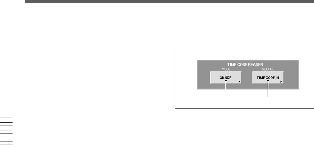
78
Chapter 3 Menu
Chapter 3 Menu
Menu Windows
A MODE button B SOURCE button
B MAIN PLL status
Displays the status of PLL which generates clock
signals used internally by the unit.
LOCK: Operating correctly.
UNLOCK: Synchronization is lost. When the word
clock signal is selected as the reference signal, check
the setting of the terminated resistor or if the word
clock selector is set correctly. Check whether the
device that supplies the clock signal is working
correctly.
When INTERNAL or VIDEO is selected as the
reference signal, the unit may be defective.
NO WORD: The word clock signal is not input.
When WORD CLOCK is selected as the reference
signal, check the setting of the terminated resistor or if
the word clock selector is set correctly. Check whether
the device that supplies the clock signal is working
correctly.
When INTERNAL or VIDEO is selected as the
reference signal, the unit may be defective.
4 CHANGE button
Touch this button to change the setting of the SYNC
CLOCK section. A dialog box appears. After
confirming, select [OK]. The unit restarts and the
settings are changed.
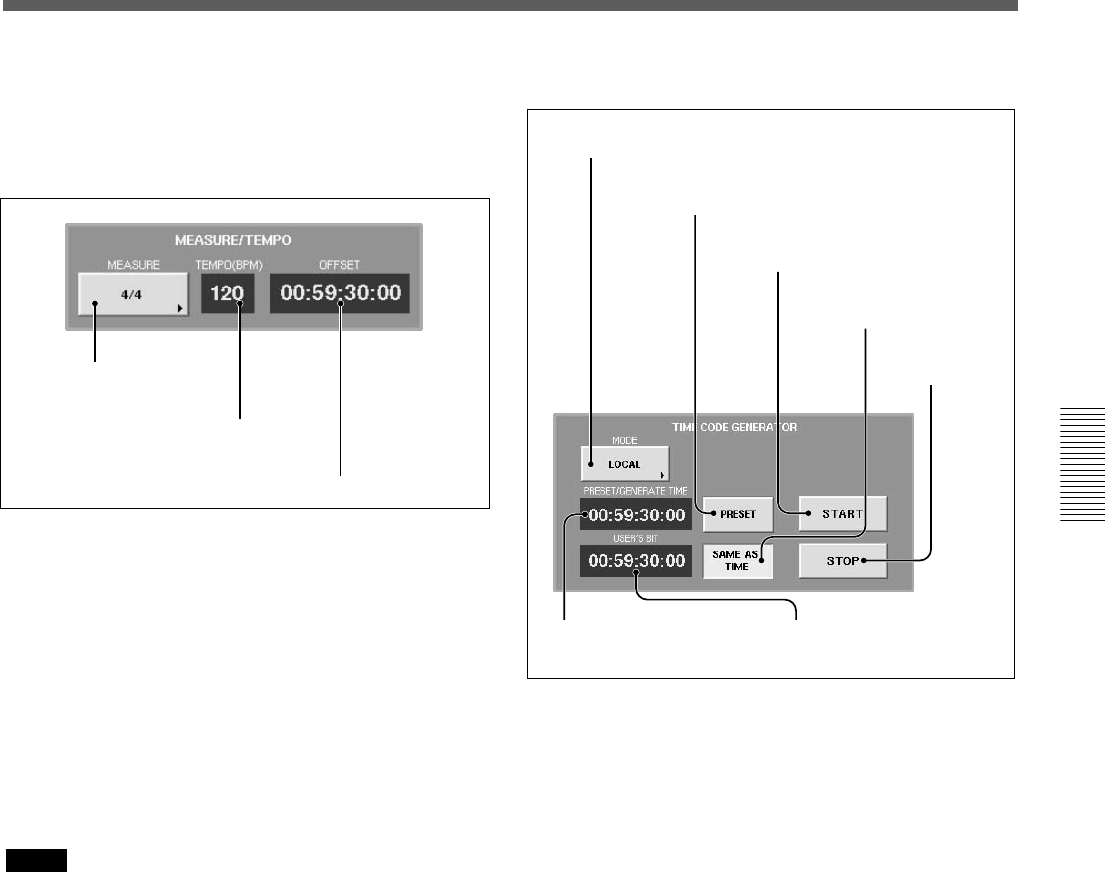
79
Chapter 3 Menu
Chapter 3 Menu
A MODE button
B PRESET button
C START button
D SAME AS TIME button
E STOP button
FPRESET/GENERATE
TIME display window
A MEASURE selector
B TEMPO display window
C OFFSET display window
6 MEASURE/TEMPO section
When the BARS button is lit on the timecode input
section on the Automation panel, the beats and bars
are calculated on the settings entered in this section.
7 TIME CODE GENERATOR section
A MODE button
Touch this button to set the operation mode of the
built-in timecode generator.
•LOCAL
The timecode can be run and stopped using the
START/STOP buttons.
•SLAVE LOCK
Generates the timecode based on the timecode read
by the built-in reader.
•SLAVE LOCK (AUTO RUN)
Once the timecode read by the built-in reader runs
correctly, the timecode is generated as running
automatically generated regardless of the incoming
timecode.
•EMULATE MTR
Controls using the machine control functions of the
unit as the emulation machine. In this mode, a
LOCATE command will produce a burst or timecode,
allowing the machine using the timecode chase to
locate.
A MEASURE selector
Selects the measures of a tune.
First level: n/2, n/4, n/8, n/16
2nd level: n
B TEMPO display window
Touch this part to select and enter the tempo.
C OFFSET display window
Touch this part to select and enter the timecode of the
first beat of the first measure.
Notes
•The values of the measure, beats and MIDI clocks
displayed when pressing the BARS button on the
Automation panel are estimated values obtained by
converting the timecode value based on the
information set by MEASURE/TEMPO section. The
greater the difference from the timecode set on the
OFFSET display window is, the greater the error is.
•The automation operation is executed based on the
timecode regardless of the setting of the BARS
button.
GUSER’S BIT display
window

80
Chapter 3 Menu
Chapter 3 Menu
Menu Windows
B PRESET button
Touch this button to set ON. You can enter and display
the preset time on the PRESET/GENERATE TIME
display window.
When the LOCAL mode is selected, touching START
will generate timecode from the preset time.
Enter the timecode using the keyboard connected to the
unit or on the KEYBOARD window after touching the
PRESET/GENERATE TIME display window.
C START button
When the generator is in LOCAL mode, touching the
START button will make the timecode start running
from the preset value.
D SAME AS TIME button
Touch this button to set the user bits to the same value
as the current timecode.
E STOP button
Touch this button to stop the generator, when in
LOCAL mode or SLAVE LOCK (AUTO RUN) mode.
F PRESET/GENERATE TIME display window
Displays the preset time or the generated timecode
according to the PRESET button status.
G USER’S BIT display window
Displays and enters the timecode user bit data. Enter
the user bit using the ten key pad after touching this
display window. The values that can be entered are 0 to
9. A, B, C, D, E and F can not be entered.
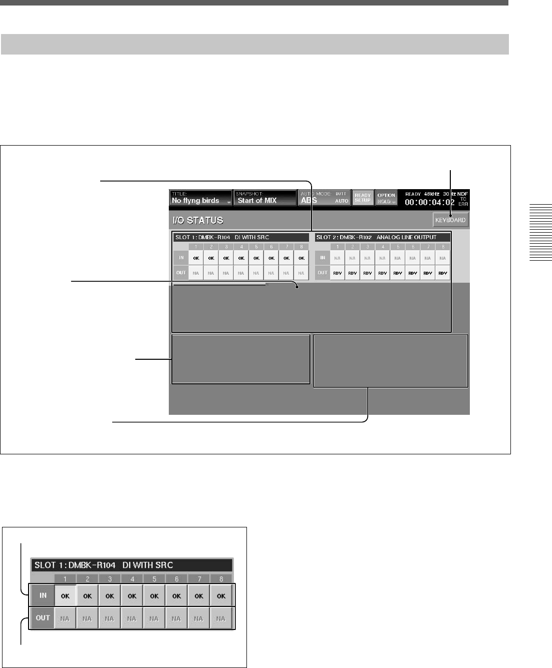
81
Chapter 3 Menu
Chapter 3 Menu
I/O STATUS Window
To open this window, touch the SYSTEM button on
the bottom menu bar, then select the I/O STATUS on
the menu.
This window allows you to check the performance of
the digital audio input/output.
KEYBOARD window button
1 SLOT 1 to 4 section
4 INFORMATION section
1 SLOT 1 to 4 section
Displays the name and function of the board inserted
into the four slots on the unit. It also displays the status
of the input/output signals.
A IN buttons
B OUT buttons
A IN buttons
On these buttons, OK, NA, or !xxx is displayed as the
status of the input signal of the channel.
By touching this button, the details of the input signal
of the channel are displayed on the INFORMATION
section 4 .
The status displays have the following meaning.
•OK
Indicates that the signal is inputted correctly.
•NA (Not Available)
Indicates that the input signal cannot be used.
•!xxx
Indicates that there is trouble in the input signal.
In this case, touch this button to display the details
on the INFORMATION section and check the status.
When !UNLC (unlock) is displayed, the input’s PLL
cannot be locked.
2 DA 88 button
3 BUILD-IN DIGITAL I/O section
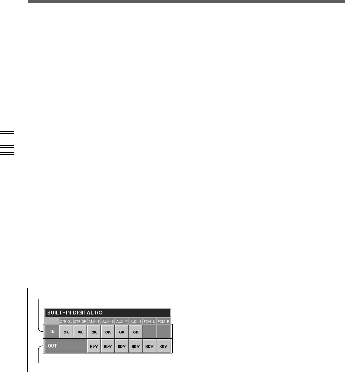
82
Chapter 3 Menu
Chapter 3 Menu
Menu Windows
A IN buttons
B OUT buttons
When !SLP (SLIP) is displayed, the input signal is
not synchronized to the unit.
B OUT buttons
On these buttons, RDY or NA is displayed as the
status of the output signal of the channel.
By touching this button, the details of the output signal
of the channel are displayed on the INFORMATION
section 4.
The content of the display is as follows:
•RDY (ready)
Indicates that this channel can be used as the output
signal.
•NA (Not Available)
Indicates that this channel cannot be used.
2 DA 88 button
This button is displayed only when the DMBK-R107
is inserted into the slot.
When you have interfaced a DA-88 manufactured by
the TEAC corporation with a DMBK-R107 Interface
Board, touch this button to set it to ON (lit in green).
When you use an another TDIF device, set this button
to OFF.
If this button is not turned on (lit in green) with a DA-
88 inserted into the slot, it is necessary to replace the
ROM in the DMBK-R107 slot. Contact your Sony
dealer.
3 BUILT-IN DIGITAL I/O section
Displays the status of the signal of the built-in digital
input/output connectors.
A IN buttons
On these buttons, OK, NA, or !xxx is displayed as the
status of the input signal.
By touching this button, the details of the input signal
of the channel are displayed on the INFORMATION
section 4 .
The content of the display is as follows:
•OK
Indicates that the signal is inputted correctly.
•NA (Not Available)
Indicates that this channel cannot be used as the
output signal.
•!xxx
Indicates that there is trouble in the input signal or
attention is required.
In this case, touch this button to display the details
on the INFORMATION section and check the status
of the input signal.
When !UNLC (unlock) is displayed, the input’s PLL
cannot be locked.
When !SLP (SLIP) is displayed, the input signal is
not synchronized to the unit.
B OUT buttons
On these buttons, RDY or NA is displayed as the
status of the output signal of the channel.
By touching this button, the details of the output
signal of the channel are displayed on the
INFORMATION section 4.
The content of the display is as follows:
•RDY (ready)
Indicates that this channel can be used as the output
signal.
•NA (Not Available)
Indicates that this channel cannot be used as the
output signal.
4 INFORMATION section
Displays detailed information on the signal selected
by SLOT 1 to SLOT 4, the IN button or OUT button
on the BUILT-IN DIGITAL I/O section.
The following items are displayed as the detailed
information of the signal:
•DIPLL
Displays the status of the lock of the PLL built in
each input path.
LOCK: Displays that the PLL is correctly locked.
UNLOCK: Displays that the PLL is not locked. In
this case, “----” is displayed on the remaining
information items.
•DATA
Displays the status of synchronization between the
signal and the unit.
NORMAL: Indicates that they are correctly
synchronized.

83
Chapter 3 Menu
Chapter 3 Menu
SLIP: Asynchronization causes interpolation or
cropping of data. This results in noise or distortion.
Check that the unit synchronizes with each unit
correctly.
However, when the sampling converter is effective
on the DMBK-R104, there is no problem even if
SLIP is displayed.
•VALIDITY
Displays the status of the VALIDITY flag of the
AES/EBU digital audio signal.
NORMAL: Indicates that the VALIDITY flag bit is
0.
INVALID: Indicates that the VALIDITY flag bit is
1. This signal is not suitable as an audio signal.
•CRC
Displays the result of the CRC check of the channel
status of the AES/EBU digital audio signal.
NORMAL: Indicates that there is no trouble.
ERROR: Indicates that there is some trouble with
the results of the CRC check. For the items after
CRC, such as AUDIO, CH MODE and so on, NA is
displayed.
•AUDIO
Displays the mode of the digital audio signal.
PROFESSIONAL: Indicates that the signal is sent
from equipment for broadcasting studio.
NON AUDIO: Indicates that the signal is not an
audio signal.
CONSUMER: Indicates that the signal is sent from
equipment for consumer use.
COPY IHN: Indicates that the signal is sent from
equipment for consumer use and has a copyright.
•CH MODE
Displays the mode of the digital audio signal. 2 CH
or STEREO is displayed depending on the definition
of the channel status.
•EMPHASIS
Displays the status of emphasis of the digital audio
signal.
ON: Indicates that the signal is a preemphasised
digital audio signal.
OFF: Indicates that the signal is not a preemphasised
digital audio signal.
•FS
Displays the sampling frequency of the digital audio
signal.
•ORIGIN
Displays the ORIGIN information written in the
channel status of the AES/EBU digital audio signal
in four characters.
When the OUT button is selected, after touching this
row, you can enter the information using the keyboard
or on the KEYBOARD window.
•DESTINATION
Displays the DESTINATION information written in
the channel status of the AES/EBU digital audio
signal in four characters.
When the OUT button is selected, after touching this
row, you can enter the information using the keyboard
or on the KEYBOARD window.
•DE EMP button
Touch this button to set whether the digital audio
signal is emphasised or deemphasised.
AUTO: Indicates that the digital audio signal is
automatically deemphasised according to the
emphasis flag.
ON: Indicates that the digital audio signal is
deemphasised regardless of the emphasis flag.
OFF: Indicates that the digital audio signal is not
deemphasised regardless of the emphasis flag.
Notes
•INSERTION return 1 to 8 do not have the deemphasis
function.
•When the digital audio signal is used as INSERTION
return 1 to 8, set the emphasis of the effector’s output
to off.
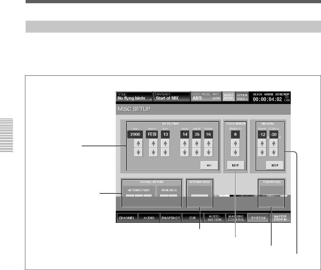
84
Chapter 3 Menu
Chapter 3 Menu
Menu Windows
3 MTR BUS MODE section
4 TOUCH SENSOR section
5 TOUCH PANEL section
6 DIM LEVEL section
1 DATE/TIME section
2 CHANNEL METERS section
MISC SETUP Window
1 DATE/TIME section
Sets the built-in clock.
YEAR
MONTH
DAY
HOUR (24-hour time display system)
MINUTE
SECOND
v/V buttons: Increases or decreases the value.
SET button: Touch this button to adjust the time of
the built-in clock.
To open this window, touch the SYSTEM button on
the bottom menu bar, then select “MISC SETUP” on
the menu.
This window allows you to control and check settings
for the system’s clock, the channel meter display, the
sensitivity of the touch sensor and the dimmer level of
the monitor signals.
2 CHANNEL METERS section
Sets the peakhold of the master meter and channel
meters and selects the signal which is to be displayed
on the channel meters.
When the channel faders are used as faders for AUX
SEND 1 to 8 or MTR bus, the meters display the level
of the bus signal.
METERING POINT button
Selects the point in the signal path to be displayed.
INPUT button: Selects the signal of the point just
before the ∅ switch (phase inversion) of the input
signal path.
PRE (prefader) button: Selects the signal of the point
located before the CUT switch of the input signal path.

85
Chapter 3 Menu
Chapter 3 Menu
PST (post fader) button: Selects the signal of the
point located before the pan of the input signal path.
For AUX send, MTR bus and PGM, the signal after the
master fader is selected.
PEAK HOLD button
Selects the method used to display the peak hold level
of the input signals.
MAN (manual) button: Touch this button to always
display the maximum level of the input signal
(peakhold status). Touch this button again to cancel the
display of the peakhold status.
AUTO button: Touch this button to display the peak
level of the input signal for three seconds, and the hold
display is automatically reset.
3 MTR BUS MODE section
Touch the button to display SURROUND. When
SURROUND is displayed, the MTR bus is set to
surround mode. When the display is off, the MTR bus
is set to mono/stereo mode.
4 TOUCH SENSOR section
Sets the sensitivity of the fader touch sensor.
SENSITIVITY display: Displays the sensitivity as
steps of 0 to 15. The maximum sensitivity is 15.
v/V buttons: Increase or decrease the sensitivity.
KEEP button: Touch this button to store the
sensitivity on the SENSITIVITY display window in
the current title. At the same time, data in the work
area is also stored in the current title.
5 TOUCH PANEL section
Calibrates the touch panel.
When the cursor does not move correctly, calibration
of the touch panel is required.
Touch the button to open the calibration window.
To calibrate the touch panel, proceed as follows:
1Turn off the power and connect a mouse to the
MOUSE connector on the rear panel. Then turn on
the power again.
2Select the CALIBRATE button on the TOUCH
PANEL section.
A dialog box appears.
3Select [YES] on the dialog box.
The calibration window appears.
4Touch the CALIBRATE button on the window.
Perform the following operations, step 5 to step 7,
according to the blue arrow indicated on the
calibration window.
5Touch the left top of the window according to the
blue arrow indication.
The blue arrow indication turns red. By touching
the left top again, the arrow turns blue and points
to the right bottom.
Note
The arrow indicates the corner to be touched. Be
careful not to touch the arrow itself. If you touch
the arrow accidentally, start the calibration
operation again from step 1.
6Touch the right bottom on the window according
to the blue arrow indicator.
Touching the arrow at the first time causes the
blue arrow to turn red. Touching the red arrow
causes a circle mark to appear at a point a little to
the right of the center.
Note
Be careful not to touch the arrow.
7Touch the circle mark on the window.
8Touch the EXIT button to terminate the
calibration.
The calibration of the touch panel is terminated.
Note
If you fail to calibrate the touch panel, you won’t be
able to operate the touch panel. If you fail, open the
CALIBRATION panel using the mouse connected to
the MOUSE connector again, then perform operations
of step 5 to 8 again.
6 DIM LEVEL section
Adjusts the dimmer level of the monitor signals.
v/V buttons: Increase or decrease the dimmer level of
the CR MON (control room monitors) or STUDIO LS
(studio monitors). The adjusted values are displayed
on the display windows.
KEEP button: Touch this button to store the dimmer
level displayed on the window in the current title. At
the same time, data in the work area is also stored in
the current title.

86
Chapter 3 Menu
Chapter 3 Menu
Menu Windows
KEYBOARD Window
To open this window, touch the KEYBOARD button
on the SNAPSHOT, CUT, TITLE MANAGER,
MACHINE CONTROL, SYNC/TIMECODE or I/O
STATUS window.
1 Entry display area
Displays the characters entered.
When the item is already named on the window
opened before the KEYBOARD window opens, that
name is displayed here.
2 BACK SPACE button
Deletes the character placed before the cursor.
3 CANCEL button
Clears the characters entered in the entry display area
1 and closes the KEYBOARD window. The original
name is not replaced.
4 CAPS LOCK button
Touch this button to enter the alphabetical characters
from A to Z in capitals. Numeric numbers and symbols
are not affected by this button.
5 SHIFT button
Touch this button to set the shift function to ON to use
the upper symbols on the numerical and symbol
buttons.
The SHIFT button is reset to OFF when you have
entered one character.
6 ENTER button
Enters the name entered in the entry display area,
replaces the name on the window opened before the
KEYBOARD window opens. Pressing the ENTER
button also closes the KEYBOARD window.
1 Entry display area 2 BACK SPACE button
3 CANCEL button
4 CAPS LOCK button 5 SHIFT button
6 ENTER button
87
Chaper 4 Operation Tips
Chapter 4 Operation Tips
For System Setup
Changing the Keyboard Type
The DMX-R100 is factory-preset for use with a Japanese type keyboard.
Select the desired keyboard type as described below.
1Turn on the power of the DMX-R100.
“Loading Now........” appears.
2While the numbers of dots on the screen is increasing, press [K] on the
keyboard currently connected.
The following dialogue appears;
“Do you want to change the keyboard type?
f : French keyboard (fr_FR_102.kbd)
g : German keyboard (de_DE_102.kbd)
j : Japanese keyboard (ja_JP_106.kbd)
u : US keyboard (en_US_101.kbd)
other : Don’t change the keyboard type.”
3Touch the character of the desired keyboard type; “f”, “g”, or “u”.
The keyboard type indication on the bottom left of the window
changes to the one selected.
Updating the DMX-R100 System
When you turn on the power of the DMX-R100, the starting-up window
opens.
After the starting-up window closed once, the bar indication [–] starts to
blink on the left top of the LED window.
While the bar indication [–] is blinking, if you press the ESC key on the
external key board, the following dialogue appears:
“Will you update this system? (y/n)”
If the above dialogue appears on the window, be sure to select “N”.
The system starts as usual.
WARNING
If you press “y” on the key board, without having the floppy disks for
updating system, the DMX-R100 system files may be damaged.
If you need update the system, contact your nearest Sony dealer.
Chapter 4 Operation Tips
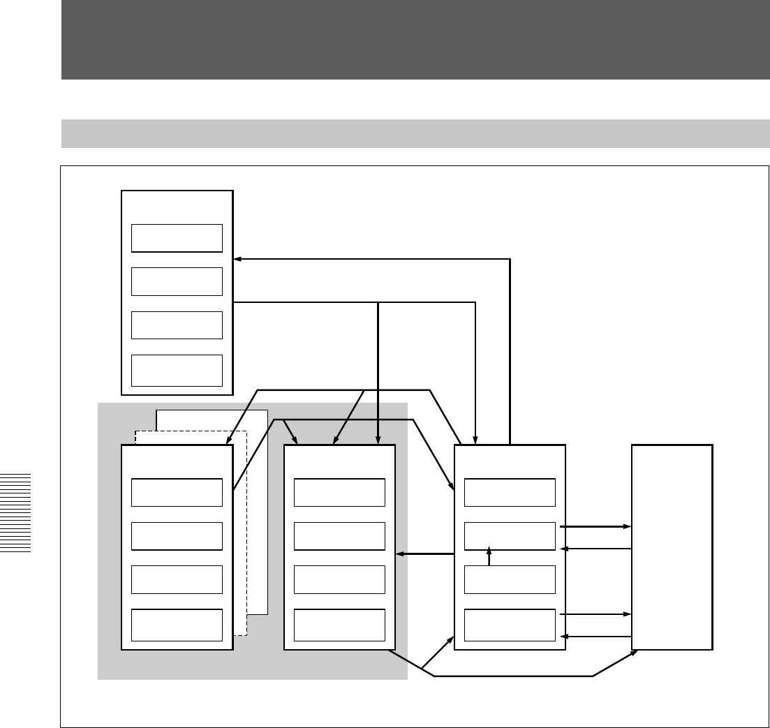
88
Chaper 4 Operation Tips
Chapter 4 Operation Tips
Memory Structure and Title
Structure of Snapshot and Automation Memory
The above figure shows the memory structure of the unit.
Automation data, snapshot data and cue data created on the unit are stored,
updated and deleted on the dynamic RAM. Thus, when restarting the unit
or turning off the power of the unit, this data is lost.
To save the data that are being operated on the unit, select KEEP from the
TITLE menu which opens by touching the TITLE button on the top bar on
the window (in this manual, this operation is also called KEEP’d). Data in
the work area on the dynamic RAM is saved in the current title which is
the backup file in the flash memory. Thus, the data is not lost when
restarting or turning off the power of the unit. You can save the current
title as the title with the title number and title name on the TITLE
MANAGER window.
Also, you can initialize the title by using the CLEAR button of CURRENT
TITLE on the TITLE MANAGER window. In this case, the timecode and
the sampling frequency of the title being used are stored. However, the
remaining data items (such as automation data, snapshot data and cue data)
are cleared.
Floppy disk
Title config
Snapshot
Cue
Automation
Buffer A or B
Saved into the floppy disk
Loaded from the floppy disk
SAVE
Title #10
Title #1
Title config
Snapshot
Cue
Automation
Buffer A or B
Current title
Title config
Snapshot
Cue
Automation
Buffer A or B
Built in flash memory
LOAD
Dynamic RAM
Title config
Snapshot
Cue
TC LINK
Automation
Buffer A or B
KEEP
RECALL
STORE
RECALL
WRITE
When turning on the power
Console panel/
DSP

89
Chaper 4 Operation Tips
Chapter 4 Operation Tips
About Titles
In operating the unit, data such as snapshots, dynamic automation data,
sampling frequencies and timecode required for the mixing operation are
stored in ‘Titles’.
There are two types of titles: One is the “current title” automatically
created in the flash memory, the other is the title stored as a file.
For detailed information on how to create a title, see “TITLE MANAGER
Window” on page 72.
Initializing a title (CURRENT TITLE CLEAR)
A new current title which has no data is created based on the current
sampling frequency and timecode mode setting. At this time, all data other
than the sampling frequency and timecode are cleared.
The current title is the work title created in the memory or flash memory.
Saving a title
The current title is saved into the specified TITLE number.
Loading a title
The specified title is loaded in the current title.
If the setting for Fs (sampling frequency) and/or SYNC SOURCE is
different between the loaded title and current title, the unit restarts after
giving a confirmation message.
Changing the sampling frequency
When you change the sampling frequency, the contents of the current title
is cleared.
Titles when turning on the power of the unit
When there are created titles
•The sampling frequency, sync source and timecode mode are set on the
unit according to the content of the existing title.
•The current title worked on just before turning off the unit is
automatically loaded. The initial cue is automatically recalled and the
dynamic automation data is automatically loaded into the effective
buffers.
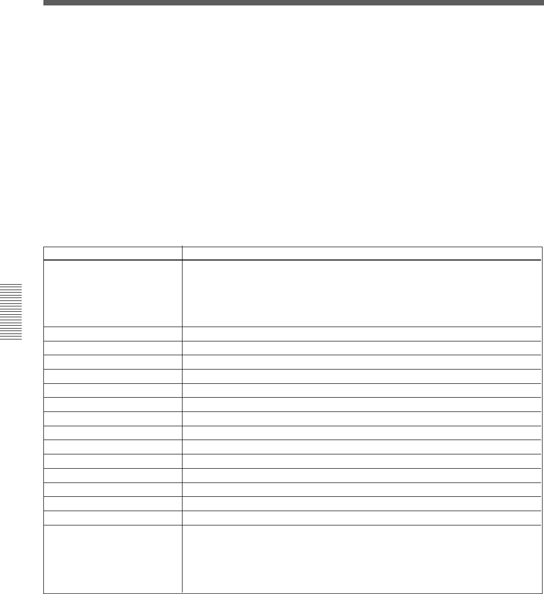
90
Chaper 4 Operation Tips
Chapter 4 Operation Tips
Setting
•Connect AD 1 to 24 to CH-1 to CH-24.
•When the DMBK-R105 is inserted in the option slot, connect each input channel of the
DMBK-R105 to Insertion return 1 to 8.
•When the DMBK-R101/103/104/106/107 is/are inserted, connect them starting from the
lowest slot number to the channels from CH-25 in order.
Monaural
0 dB
0 Frame, COARSE: OFF
Control: Center, Button: ON
Front center
100 %
OFF
PGM L/R: ON
Control : Center, Button: OFF
Control :Center, Button: OFF, EXPANDER: Access
Set all busses to monaural, OFF and POST
Set all groups to GANG and OFF.
OFF
- infinity
•Connect PGM L/R busses to the PGM L/R connectors.
•Connect the AUX 1 to 8 busses to the AUX 1 to 8 connectors.
•When the DMBK-R105 is inserted in the option slot, connect each output channel of the
DMBK-R105 to insertion send 1 to 8.
•When the DMBK-R102/103/106/107 is/are inserted.
Item
Input routing
Channel mode
Trim setting of the input signal
Delay amount
Pan, MTR pan
Surround pan
Divergence
MTR assign
PGM assign
Equalizer
Dynamics
AUX send
Fader group
Cut
Fader
Output routing
Memory Structure and Title
When you use the unit for first time (with the default setting) or
there are no current files
Create the current title with the following settings for the synchronous
signal and timecode mode:
For detailed information on how to set these items, see “SYNC/TIME CODE
Window” on page 76.
•Sampling frequency: 48 kHz
•Sync-lock (reference synchronous signal): INTERNAL
•Timecode mode: NTSC30NDF
Create the initial cue and snapshot with the following settings:
•Initial cue: 00:00:00:01
•Snapshot: not linked.
Default setting of the unit

91
Chaper 4 Operation Tips
Chapter 4 Operation Tips
Basic Operation Procedure
Basic Mixer Operation Flow from Turning On to Monitoring
The basic mixer operation is explained in the following operation flow
chart.
Example: In the following flow chart, audio from the microphone
connected to the IN A connector is routed to CH 1 and the fader is used as
a channel fader. Then the signal is output to the PGM bus and monitored
on the control monitor. The unit is used in manual mode.
For detailed information on operations, see the page in parentheses.
Turning on the power
The unit starts after 1 minute.
Loading the existing title or creating a new title.
On the TITLE MANAGER window (page 72), you can create a new title
or load the existing title.
Confirming/changing the sampling frequency and timecode
On the SYNC/TIME CODE window (page 76), confirm the sampling
frequency, the source of the synchronous signal, and the timecode mode.
If they are not set to the desired settings, change the settings.
Disabling automation operation
•Press the TC LINK button on the Automation panel (page 25) to OFF.
•Press the AUTOMATION OFF button so it is lit (i.e. off).
Routing the input signal
Confirm that AD 1 is routed to CH 1 on the AUDIO INPUT ROUTING
window (page 55).
Also, you can select AD 1 from the list of the input sources on the
SOURCE section of the INPUT section on the INPUT/PAN/ASSIGN
window (page 44).
(Change the audio input routing as required.)
Routing the output signal
Confirm that the PGM bus is routed to the PGM output connector on the
AUDIO OUTPUT ROUTING window (page 57).
(Change the audio output routing as required.)
To the next page
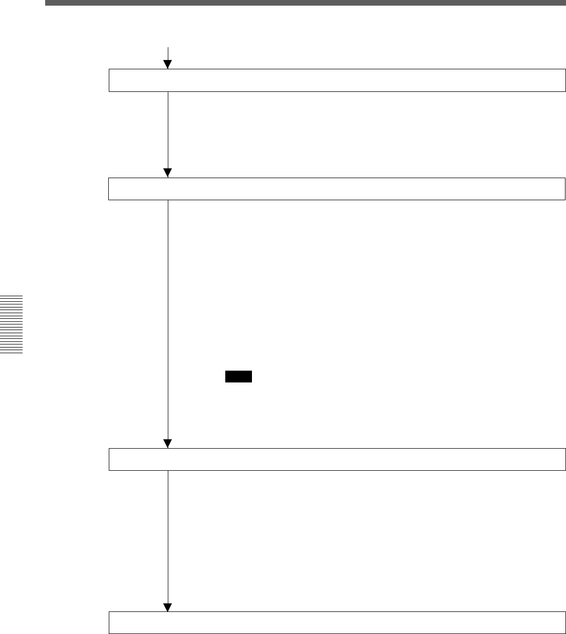
92
Chaper 4 Operation Tips
Chapter 4 Operation Tips
Basic Operation Procedure
From the previous page
Confirming/setting monitoring
•Select the CR MONITOR tab on the MONITOR window (page 59) and
confirm that CUT L/CUT R buttons are set to OFF. (Change the settings
as required.)
•Press the PGM button on the SOURCE section on the control room
monitor section on the unit (page 24) so that the button lights up.
Setting the analog head amplifier
•Select the INPUT button on the CHANNEL METERS section on the
MISC SETUP window (page 84).
•Release the INPUT B button on the Analog head amplifier panel (page
11) so that the button is not lit. The IN A connector becomes active.
•Watching the meter of the channel (in this example, CH 1) connected to
the corresponding head amplifier, adjust the gain using the GAIN control
on the Analog head amplifier panel.
•In this example, set the PAD button on the Analog head amplifier panel
to OFF to connect the microphone. (Set the PAD button to on or off, as
required.)
•Depress the + 48 V button on the Analog head amplifier, as required.
Note
When devices other than microphones that cannot receive power from the
external unit are connected to the IN A connector, release this + 48 V
button (not depressed). If you set this button to ON, the connected external
unit may be damaged.
Setting the channel
•Press the ACCESS button on the channel strip panel (page 12) for CH 1
on the unit so that the button lights up.
•Press the PROGRAM L/R buttons on the BUS ASSIGN section (page
18) on the unit. (The signal of the channel is assigned to the PGM bus.)
•Set the level of the PROGRAM fader to 0 dB. (Change the level of the
PROGRAM fader, as required.)
•Watching the master meter (page 22), adjust the level using the channel
fader.
•Adjust the monitor sound volume using the controls on the Control room
monitor section (page 24).
Storing the channel settings as data
•To store the channel data, store it as snapshot data using the STORE
button on the SNAPSHOT window (page 64).
•When restarting the unit or turning off the power of the unit, save data by
selecting KEEP on the TITLE menu which opens by touching the TITLE
button.

93
Chaper 4 Operation Tips
Chapter 4 Operation Tips
Using the stereo signal
When setting PAN of the channel to OFF
1Display “STEREO” on the MODE button by touching it on the
INPUT/PAN/ASSIGN window (page 44).
2Set the PAN button to OFF on the INPUT/PAN ASSIGN window.
3Perform settings for the PROGRAM L/R buttons on the BUS ASSIGN
section on the Parameter setting panel.
•For the L channels (usually the odd channels), set the PROGRAM L
button to ON and the PROGRAM R button to OFF.
For the R channels (usually the even channels), set the PROGRAM R
button to ON, and the PROGRAM L button to OFF.
You can also set the PROGRAM L/R bus on the ASSIGN section on
the INPUT/PAN/ASSIGN window.
•Select the status of the REVERSE button, the L + R button and the
MS DECODE button on the INPUT/PAN/ASSIGN window, as
required.
When setting PAN of the channel to ON
1Display “STEREO” on the MODE button by touching it on the
INPUT/PAN/ASSIGN window (page 44).
2Set the pan of odd and even channels to ON.
3Set the PROGRAM L/R buttons in the BUS ASSIGN section on the
Parameter setting panel to ON.
4Turn the pan control of the odd channel fully counterclockwise.
5Turn the pan control of the even channel fully clockwise.
6Adjust the panning settings of the odd and even channels as required.
Note
For channels set in stereo, you have to perform pan/surround panning
settings for L and R independently. Perform the pan/surround panning
settings, as required.

94
Chaper 4 Operation Tips
Chapter 4 Operation Tips
Basic Operation Procedure
Snapshot Automation Procedure
The unit can memorize up to 99 control settings (snapshots).
By linking the stored snapshot settings with the timecode, the snapshot
automation operations are performed as explained below.
Since the snapshot data is stored in the working memory when storing it by
using the STORE button on the SNAPSHOT window, data stored in the
work memory is cleared when restarting the unit or turning off the power
of the unit. Store the data in the current title by selecting KEEP on the
TITLE menu which opens by touching the TITLE button, or save the data
as a title file by using the SAVE button on the TITLE MANAGER
window.
To perform operations on the unit, use the buttons, the SNAPSHOT
buttons and the ten key pad on the Automation panel.
For buttons and windows used for snapshot automation, see “Automation Panel”
on page 25, “SNAPSHOT Window” on page 64 and “TITLE MANAGER window”
on page 72.
Storing/updating a snapshot data
To store/update the snapshot data by manipulating buttons on
the unit
1Adjust or set the parameters on the unit as required.
2Confirm that the TC LINK button is set to OFF (not lit).
It is located among the SNAPSHOT buttons.
3Press the SNAPSHOT button so that the button lights up.
4Using the ten key pad, enter the number of the snapshot that you want
to store.
5Press the STORE button.
It is located among the SNAPSHOT buttons.
The control settings on the unit are stored along with the snapshot
number.
To store/update the snapshot data on the window
1Adjust or set the parameters on the unit as required.
2Open the SNAPSHOT window.
3To create new snapshot data:
Touch the NEW button to select it.
Channel processing control values are stored in a new snapshot when
the NEW button is pressed. The lowest number among the vacant
numbers is assigned and the snapshot is given “# + snapshot number”
as a temporary name.

95
Chaper 4 Operation Tips
Chapter 4 Operation Tips
4To update the snapshot data:
1Touch the number of the data that you want to update on the
snapshot list on the window.
At this time, you cannot select a not-registered snapshot.
2Touch the STORE button on the window.
The data of the selected snapshot number is replaced with the
current status of control settings on the unit.
Recalling a snapshot data
To recall the snapshot data using the ten key pad
1Confirm that the TC LINK button is set to OFF (the button is not lit).
2Press the SNAPSHOT SET button so that the button lights up.
3Enter the number of the snapshot data that you want to recall.
4Press the RECALL button on the unit.
To recall the snapshot data on the window
1Open the SNAPSHOT window.
2Touch the number of the snapshot data that you want to recall on the
snapshot list.
3Touch the RECALL button on the window.
Changing the name of the snapshot data
1Open the SNAPSHOT window.
2Touch the number of the snapshot data whose name you want to
change on the snapshot list.
3Touch the name that you want to change.
4Touch the KEYBOARD window button.
5Enter the name on the KEYBOARD window.
6Touch the ENTER button.
Deleting snapshot data
1Open the SNAPSHOT window.
2Touch the number of the snapshot that you want to delete on the
snapshot list.
3Touch the DELETE button.

96
Chaper 4 Operation Tips
Chapter 4 Operation Tips
Basic Operation Procedure
Cue Operation Procedure
Since the cue data is stored in the work memory when storing it by using
the STORE button on the CUE window, data stored in the work memory is
cleared when restarting the unit or turning off the power of the unit. Store
the data in the current title by selecting KEEP on the TITLE menu which
opens by touching the TITLE button or save the data as a title file by using
the SAVE button on the TITLE MANAGER window.
To perform the cue operation by manipulating buttons and controls on the
unit, use the buttons, the SNAPSHOT SET buttons and the ten key pad on
the Automation panel on the unit.
To perform a cue operation on the window, use the CUE window.
For details of the buttons and windows, see “Automation panel” on page 25,
“CUE window” on page 66 and “TITLE MANAGER window” on page 72.
Initial cue
•CUE 1 is reserved as an initial cue to indicate the start point of the
automation.
•When the timecode before the timecode specified for the initial cue is
entered, automation data does not become effective until the timecode
advances beyond the timecode of the initial CUE.
•To change the initial cue, perform the same operating procedure as for
changing other cue points. But if you set the timecode after the
timecode of the initial cue, automation data between the former
timecode and the timecode newly set will be lost. Similarly, you can
change the snapshot linked with the initial cue. But if you change it, an
inconsistency problem may occur between the snapshot data and the
dynamic automation data.
Storing a cue point
The operation necessary to register CUE 2 and to link with the snapshot is
explained below.
To store the cue point using the ten key pad
1Press the TC LINK button on the unit so that the button lights up.
2Create the control settings you want to store by manipulating the unit.
3Press the SNAPSHOT SET button so that the button lights up.
4Enter the desired cue number (02 in this example) using the ten key
pad.

97
Chaper 4 Operation Tips
Chapter 4 Operation Tips
5Press the STORE button on the unit.
A cue point with the specified cue number (02 in this example) is
stored and automatically linked with the new snapshot data.
To store the cue point on the CUE window
1Open the CUE window.
2Touch the NEW button.
At this time, if there are no cue points registered on the cue list, so
CUE 2 is created.
3Select the TC LINK button by touching the TC LINK button
corresponding to CUE 2.
4Touch the NUMBER button of the EVENT linked with CUE 2.
The event name list (name of the snapshot) opens.
5Select the desired event name (name of the snapshot).
The specified event (snapshot) is linked with CUE 2.
Note
If you change the time of the initial cue and the snapshot data linked with
the initial cue, the data existing between the time before the change and
after the change are lost and this may have an adverse effect on the result
after recalling automation. Take special care when updating the initial cue.
Changing a timecode of a cue point
1Open the CUE window.
2Touch the TIMECODE display corresponding to the cue point that you
want to change.
3Enter a new timecode using the ten key pad.
Or increase or decrease a value using the + / - buttons and the jog dial.
4Press the ENTER key.
Changing the snapshot data linked with the cue point
1Open the CUE window.
2Touch the NUMBER display of the EVENT of the cue point that you
want to change on the cue list.
3Touch the desired event (snapshot) on the event name list.
The event linked with the cue point is changed.

98
Chaper 4 Operation Tips
Chapter 4 Operation Tips
Basic Operation Procedure
Changing the name of the cue point
1Open the CUE window.
2Touch the CUE NAME display corresponding to the cue point that you
want to change on the cue list.
3Enter a new name for the cue point on the KEYBOARD window or
using the keyboard connected to the unit.
Deleting a cue point
1Open the CUE window.
2Touch the NUMBER display corresponding to the cue point that you
want to delete.
3Touch the DELETE button.
Only the cue point is deleted. Even if the snapshot is linked with the
deleted cue point, the snapshot data is not deleted. If you want to delete
the snapshot data too, delete the snapshot data separately.
Automation Procedure
Do not set the items to both snapshot and dynamic automation.
For example, if you want to control the fader in automation, set the faders
for the snapshot in ISOLATE mode.
Even though you can set the same item to both snapshot and automation,
the unit may perform unexpected operations.
The unit has two modes for automation: ABS (absolute) mode and TRIM
(fine adjustment) mode.
To perform automation operation, use the TC AUTOMATION buttons on
the Automation panel or on the AUTOMATION window.
For details of buttons, see “Automation Panel” on page 25, and for operations on
the window, see “AUTOMATION Window” on page 68.
Since the automation data that is being written is stored in the dynamic
RAM, data stored in the dynamic RAM is cleared when restarting the unit
or turning off the power of the unit. Store the data in the current title by
selecting KEEP on the TITLE menu which opens by touching the TITLE
button.
Or save the data as a title file by using the SAVE button on the TITLE
MANAGER window.

99
Chaper 4 Operation Tips
Chapter 4 Operation Tips
Writing automation data at the first time (in ABS mode)
1Clear the current tile on the TITLE MANAGER window. Or clear the
automation data by touching the MAKE STATIC EXECUTE button
on the AUTOMATION window.
All items subject to automation data are cleared.
Even if the timecode advances and automation is set to the RUN status
(where automation is being executed), data will not be recalled.
2Change the settings so that automation works properly to write and
recall automation data.
1Touch the ABS button on the Automation panel to select ABS
mode.
All channels are removed from dynamic automation.
2Confirm that the timecode of cue 1 (the initial cue) is set before the
project start timecode.
3Select the items to be controlled by automation using the
CHANNEL buttons in the AUTOMATION ISOLATE tab in the
SNAPSHOT window.
4Set the READY SETUP button to ON and select ALL CANCEL
using the OPTION button.
All items subject to automation are in SAFE mode.
3Create a rough mix by manipulating faders, controls and switches
currently in the status changed in step 2.
4After creating the rough mix, set the automation items you want to
record to READY.
5Confirm that the SAFE button on the panel goes off.
6Set the automation items to drop-in status (WRITE).
1Set the tape recorder to play.
2Drop in items using one of the following methods.
•Drop in items in READY status with the proper timing.
•Press the blinking WRITE button on the channel strip.
•Touch the MASTER DROP IN button on the window to turn its
color to light red.
Or you can set the tape recorder to play after setting the automation
items to WRITE mode. In this case, after the unit confirms that the
timecode has advanced correctly, the unit starts to store data.
7Store automation data by manipulating the faders, controls and buttons
as required.
(Continued)
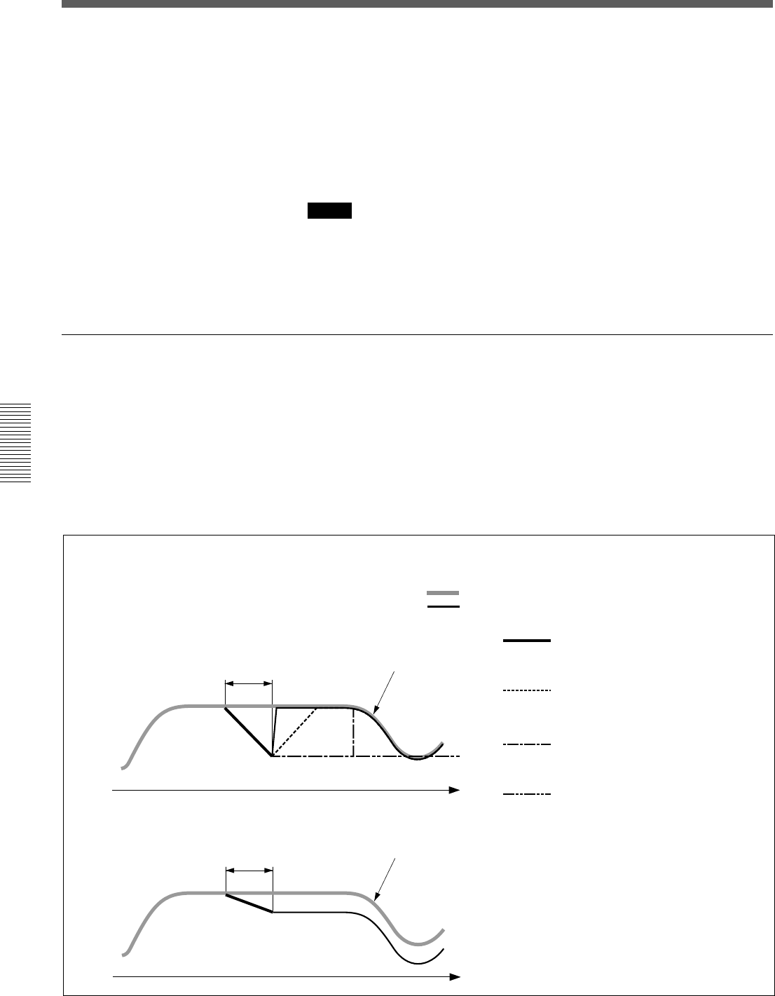
100
Chaper 4 Operation Tips
Chapter 4 Operation Tips
Basic Operation Procedure
8Drop out the automation data using one of the following methods.
•Touch the MASTER DROP IN button on the window to turn its color
to dark red.
•Touch the numerical value of the items subject to automation.
•Release the fader.
•Stop the tape recorder.
Automation data for the items set in WRITE mode in step 6 is written.
Notes
•If a lot of items are dropped in/out at the same time using the MASTER
DROP IN button, data near the drop in/drop out point may not be stored
and recalled correctly.
•Automation items in WRITE mode are removed from snapshot recall and
control from MIDI.
Updating automation data
The data of the automation items is recalled according to the timecode
entered. To update automation data, set the desired automation items to
READY, then drop them into WRITE.
You can select either ABS mode or TRIM mode to update data, using the
ABS button or TRIM button of the TC AUTOMATION buttons on the
Automation panel.
In ABS mode, you can set the speed to return to the previous data from the
new data in the AUTO RETURN TIME section in the AUTOMATION
window.
Manupulating
the fader Data stored the last time
Data stored the last time
The operation performed while holding the fader
down is added to the last stored data as offset and
recalling is continued.
The following figures show the fader operation and the results
of the fader operation.
Fader operation and its results
In the figures, the fader operations are indicated using the
following lines:
: Indicates the data stored last time (previous data)
: Indicates the actual resuts of the fader operation
(new data).
When operating the faders in ABS mode
When operating the faders in trim mode
BUTT: The fader is reset to the
position stored the last time
(previous data) at the instant you
release the fader.
RAMP: The fader is reset to the
stored position at the specified
speed, when you release the
fader.
HOLD TO NEXT: After you release
the fader, the fader’s position
remains as it is up to the next
event.
HOLD TO END: After you release
the fader, the fader’s position
remains as it is up to the end.
The previous data is overwritten.
Manupulating
the fader

101
Chaper 4 Operation Tips
Chapter 4 Operation Tips
To update automation in ABS mode
Set the tape recorder to play and set the desired automation items in
READY status. The method used to set in READY status depends on
faders, controls and buttons.
When any processing control in a channel is in READY status, the
channel’s WRITE button flashes. Also on the display, buttons display a
yellow bar and numerical values in the window change to yellow.
•To drop in faders, touch the fader knob or the numerical value displayed
on the window.
When you drop in by touching the fader knob, release the fader to drop
out (the status where WRITE is cleared).
When you drop in by touching the numerical value displayed on the
window, you can drop out using one of the following methods:
—Touch the numerical value again.
—Press the WRITE button of that channel.
—Touch the MASTER DROP IN button.
—Stop the tape recorder.
•To drop in buttons, touch them.
The button is automatically dropped in.
You can drop out using one of the following methods:
In ABS mode
—Press the WRITE button of that channel.
—Touch the MASTER DROP IN button.
—Stop the tape recorder.
In Trim mode, release the button to drop out automatically.
For items dropped in, replay of previously recorded automation is stopped
and new automation data is written.
When dropping out, faders and other controls return to the previous
automation data and replay of the previous data continues according to the
method specified in the AUTO RETURN TIME section in the
AUTOMATION window
Note
When HOLD TO END is specified, the status of faders, controls and
switches at drop out are held and stored as automation data to the end of
the title.
To update in TRIM mode
In TRIM mode, you can update previous automation data by adding
offsets.
By continuing to hold a button down, you can change the ON/OFF timing
of CUT.
Note
In TRIM mode, operation of the buttons is changed, so the audio signal is
affected when you release the button.
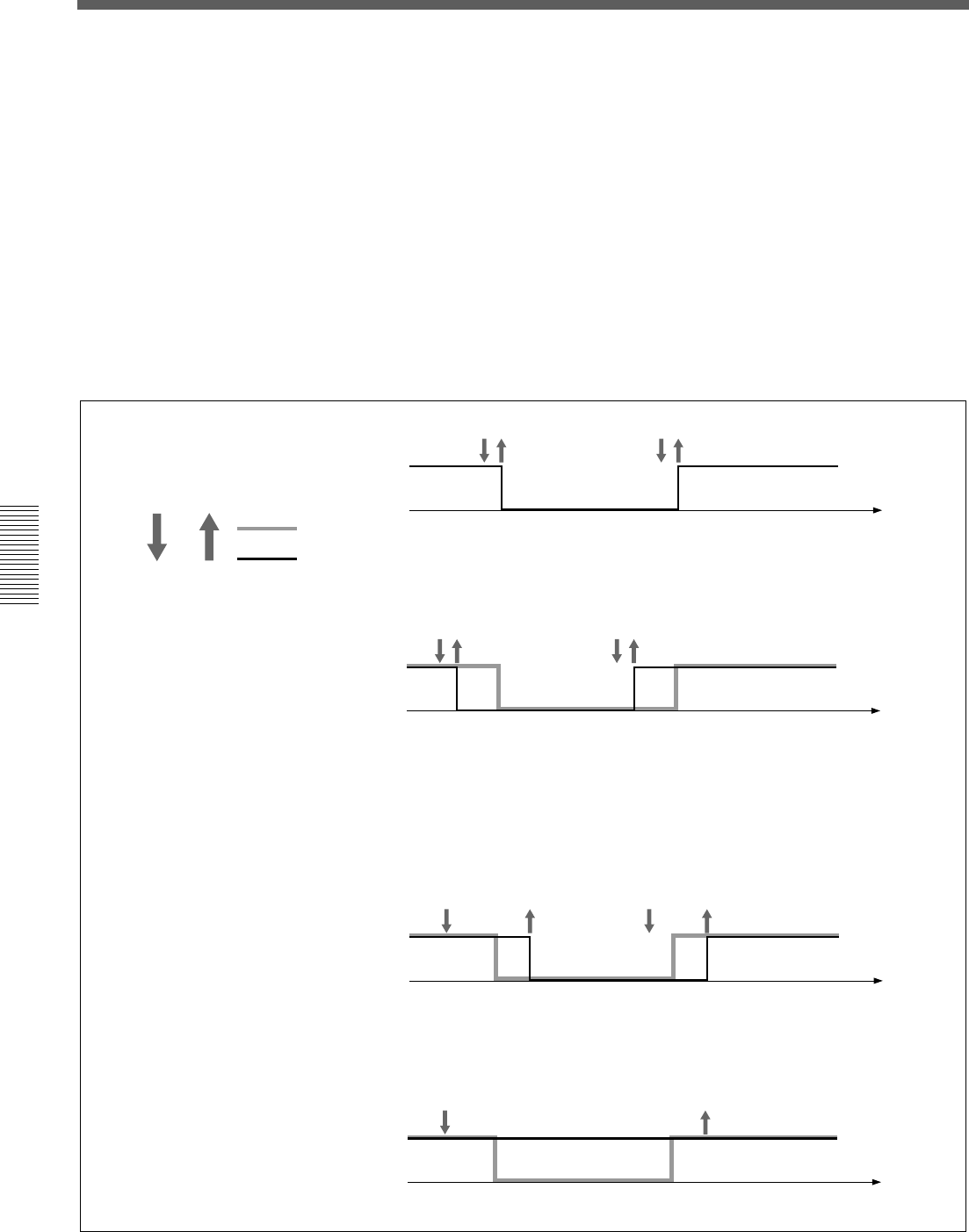
102
Chaper 4 Operation Tips
Chapter 4 Operation Tips
For example, by releasing the CUT button, the data and audio signals are
changed as follows.
1When you press the CUT button, the audio signal status is held with
the ON trigger and LEDs and ON/OFF status are inverted.
2As long as you hold down the CUT button, the audio signal status in
step 1 is held and the displays change according to the automation
operation.
3When you release the CUT button, the audio signal status is adjusted to
the display status with the OFF trigger.
The audio signal status in steps 1 to 3 is stored as automation data.
Time
Time
Press Release
When shifting the stored Cut
ON/OFF timing to an earlier
time:
ON/OFF of the CUT button:
When shifting the stored Cut ON/
OFF timing to a later time:
Press the button before the change and
release the button after timing.
Time
Time
When cancelling the stored Cut
ON/OFF:
Press the button before the change, then
release the button after the change has
been completed.
ON
trigger
OFF
trigger
Basic Operation Procedure
Cut data previsouly stored.
Cut data currently stored.

103
Chaper 4 Operation Tips
Chapter 4 Operation Tips
Using the Automatic Isolate Function
The automatic isolate function allows you to remove automation control
from selected channel or function. Using this automatic isolate function,
you can manually adjust the level, regardless of the stored automation data.
Even if the automation item is set to the isolate function, the control will
write automation data if dropped in.
This can be used as an automation mode, allowing you to stop previous
automation playback, finding a new setting of the control and dropping in.
1Set the channel or function that has the item you want to adjust to
ISOLATE in the AUTOMATION window.
2Set the item to be adjusted to READY.
3Start the tape recorder to play, and adjust the sound signal to the proper
level.
Repeat level adjustments as required.
4Rewind the tape and play it back.
5Drop it at the proper point to set the desired item to WRITE.
6Stop the tape recorder.
7Clear ISOLATE of the automation item.
Using the Write Hold Mode
After WRITE HOLD mode is set, controls hold their adjusted position
even when the timecode is stopped. This function allows you to hold the
fader group.
You can readjust the level without previously stored automation data being
replayed when timecode is stopped.
1Press the SAFE button to set it to ON (lit).
2Set the READY button on the top menu bar to ON, open the OPTION
button menu and select the WRITE HOLD mode.
3Select the FOOT SW button or AUTO button in the PUNCH IN/OUT
section in the AUTOMATION window.
Punch in/out is set.
4Set the automation item to be adjusted to READY.
5Start the tape recorder.
(Continued)

104
Chaper 4 Operation Tips
Chapter 4 Operation Tips
6Drop in the item selected in step 4.
7Adjust the level.
8Repeat the adjustment by rewinding the tape as required.
9Set the SAFE button to OFF after adjusting the level to the proper one.
10Start the tape recorder.
11Store the required duration by punching the information in/out.
You can drop out manually as required.
12Clear Punch in/out and WRITE HOLD modes.
Note
In WRITE HOLD mode, once the automation item is set in WRITE, this
WRITE mode is held until it is dropped out manually. If you do not use
the SAFE button and the punch in/out function, the automation data is
overwritten each time the tape recorder plays back.
Punching In/Punching Out
Punching in/punching out using the automation function
You can change automation data between specified durations by using the
punch in/out function.
The following example shows a case where you want to remove noise
recorded on the tape by cutting the audio with the fader.
1Find the timecodes of the start and end of the noise.
2Set the timecodes found in step 1 in PUNCH IN TIME and PUNCH
OUT TIME windows, then press the AUTO button.
The automation data is stored during the duration displayed on the
display windows.
3Rewind the tape.
4Set the SAFE button on the panel to OFF so that it goes off.
5Drop in the fader of the desired channel, and slide the fader down to
the minimum position.
The display turns in red, but data will not be written up to the PUNCH
IN point.
6Start the tape recorder to play back.
Basic Operation Procedure
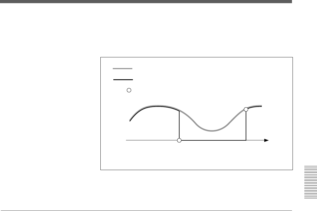
105
Chaper 4 Operation Tips
Chapter 4 Operation Tips
During the duration specified by the punch in/out function, the minimum
level is stored as automation data for the corresponding fader.
At the punch in point, the current fader level is stored. At the punch out
point, the fader level of the previous data is stored.
When the settings have been completed and everything is ready to save
them as data, select KEEP by touching the TITLE button on the window,
as required.
Performing punch in/punch out using the foot switch
Punching in/punching out using the foot switch allows you to manually
control the Drop in/out using an external foot switch.
To perform a cut operation, use the AUTOMATION buttons section on
the Automation panel on the unit and in the AUTOMATION window.
For details of buttons, see “Automation Panel” on page 25, and for operations on
the window, see “AUTOMATION Window” on page 68.
1Select the FOOT SW button on the PUNCH IN/OUT section on the
AUTOMATION window.
2Press the ABS button on the TC AUTOMATION section on the
Automation panel of the unit so that it lights up.
3Set the fader or other control whose signal you want to cut to READY.
4Drop in the fader whose signal you want to cut on the window.
The display turns in red, but data will not be written until the foot
switch is set to ON.
5Press the SAFE button on the TC AUTOMATION section on the
Automation panel of the unit so that it goes off.
Previous automation data
New automation data
Event created automatically
Punch in point Punch out point
For items in WRITE mode, the events are created automatically at the punch
in and punch out points.
(Continued)

106
Chaper 4 Operation Tips
Chapter 4 Operation Tips
6Locate the tape recorder at a point a little before the PUNCH IN time
and start to play.
7Slide the faders up to the desired level.
8Set the foot switch to ON at the desired time.
9Stop the tape recorder at the proper timing. Or switch the foot switch to
OFF.
Basic Operation Procedure

107
Chaper 4 Operation Tips
Chapter 4 Operation Tips
Dialogues on the Window
In the following cases, a dialogue box appears on the window to confirm the operation and indicate the status of
the unit. Selecting the [YES] or [CANCEL] button on the box gives the result shown in parenthesis.
Cases Dialogues and remedies
When you touch the DELETE button on the SNAPSHOT
window.
When you touch the DELETE button on the CUE window.
The sampling frequency or sync source changes
when you touch the CHANGE button on the
SYNC/TIME CODE window.
When you touch the CURRENT TITLE CLEAR button on
the TITLE MANAGER window.
When you try to save a title with a title which has
already been saved, on the TITLE MANAGER window.
When you try to delete a title which has already been
saved, on the TITLE MANAGER window.
When you try to load a title, on the TITLE MANAGER
window:
When the VIDEO is selected as the reference signal,
the VIDEO PLL is unlocked.
The MAIN PLL is unlocked
An error occurs when searching for a title saved
on the floppy disk.
“Are you sure you want to delete the selected snapshot?.”
[Yes] (The snapshot is deleted.)
[CANCEL] (Cancels the deletion.)
“Are you sure you want to delete the selected cue?”
[Yes] (The cue is deleted)
[CANCEL] (Cancels the deletion.)
“Are you sure you want to change the FS or sync source?
The current title will be lost, if you continue.”
[Yes] (The FS or sync source is changed,
and the unit restarts automatically.)
[CANCEL] (No action)
“Are you sure you want to clear the current title?”
[Yes] (The current title is cleared.)
[CANCEL] (No action)
“Are you sure you want to overwrite the saved title?”
[Yes] (The title is overwritten.)
[CANCEL] (No action)
“Are you sure you want to delete the title?”
[Yes] (The current title is deleted.)
[CANCEL] (No action)
“Are you sure you want to load the title?
The current title will be overwritten, if you continue.”
[Yes] (The title is loaded.)
[CANCEL] (No action)
“Video PLL unlocked.”
[Yes] (The dialogue is closed.)
Remedy: Confirm that the correct reference video
signal is inputted and the video signal path is
correctly terminated.
“MAIN PLL unlocked.”
[Yes] (The dialogue is closed.)
Remedy: Confirm that the signal selected as the
SYNC source is inputted correctly.
“There are no titles or this is an unformatted disk.
Check the media in the floppy disk drive.”
[Yes] (The dialogue is closed.)
Remedy: Ignore the dialogue when the disk is
already formatted and no title is saved on it. In any
other case, format the floppy disk.

108
Chaper 4 Operation Tips
Chapter 4 Operation Tips
Cases Dialogues and remedies
The title files are corrupted.
The storage space is insufficient to save the current title.
Load error occurs.
While saving a title, a write error occurs.
The current title is corrupted when starting up the unit.
The file of the title to be loaded is corrupted.
When you touch the CALIBRATE button on
the TOUCH PANEL section of the MISC SETUP window.
“Corrupted title files.
Do you want to initialize all titles?”
[Yes] (The corrupted title files are deleted.)
“Insufficient storage space.
You must delete unnecessary file(s) first.”
[Yes] (The dialogue is closed.)
Remedy: Delete any unnecessary file(s) . Or save the
title on a floppy disk.
“Load error.
Current title cleared.”
[Yes] (The dialogue is closed.)
Remedy: If the load error occurs again after
reloading, the title or the media is corrupted.
If this dialogue appears while loading up a title from
the flash memory, delete the title.
Note that when this dialogue appears, the current
title is cleared.
“Save error.”
[Yes] (The dialogue is closed.)
Remedy: While saving on a floppy disk, check that
the write-protect tab is set to the protect position or
not. While saving on the flash memory of the unit,
retry saving.
“Corrupted title file.
The current title is initialized.”
[Yes] (The corresponding title is initialized
to the default setting.)
“Corrupted title file.
This title is deleted.”
[Yes] (The corresponding title is cleared.)
“Is a PS2 mouse connected to mouse port?
Without a mouse, you cannot re-calibrate the touch screen,
if you fail to calibrate it successfully.”
[Yes] (Execute the calibration program of
the touch panel.)
[Cancel] (No action)
NOTE
Be sure to calibrate the touch panel with a mouse
connected. If you fail calibration, re-calibrate the touch
panel using the mouse.
Dialogues on the Window

109
Chaper 4 Operation Tips
Chapter 4 Operation Tips
Cases Dialogues and remedies
When you execute to load or save the title
while automation is being run:
The tape recorder does not start operation
even though 2 seconds have elapsed
when MIDI controlling the tape recorder.
When you copy data between the buffers A and B:
When you execute MAKE STATIC function:
When you try to change the initial cue
while automation is being run:
There are cues to be deleted
if you change the timecode of the initial cue.
You try to create the cue with the timecode
that is a lower value than the Cue 1 value.
“No file access while automation is in ‘RUN’.”
[OK] (No action)
“Switching MIDI Machine Control to OPEN LOOP.”
[OK] (Switched in open loop control
mode.)
“Are you sure you want to copy automation data?
Destination buffer will be overwritten”
[Yes] (Execute copying.)
[Cancel] (No action)
“Are you sure you want to erase automation data?”
[Yes] (Execute erasing automation data.)
[Cancel] (No action)
“Initial cue timecode value can not be changed, while
automation is in ‘RUN’”
[OK] (No action)
“You are changing initial cue timecode value. Cue(s)
proceeding the initial cue timecode value will be deleted.”
[Yes] (The timecode is changed)
[Cancel] (No action)
“The cue has not been stored as the timecode value is
before the initial cue.”
[OK] (No action)
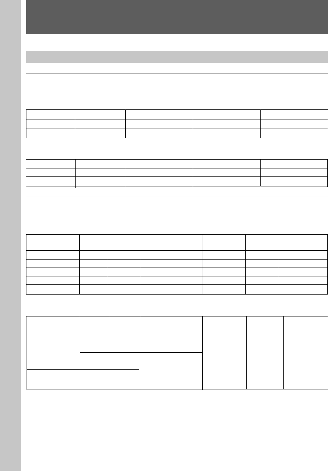
110
Appendix
Appendix
Specifications
Input/Output Connectors
Digital audio input/output
Digital input connectors
Connector Number of inputs Number of channels Connector type Signal format
AUX RET 5/6, 7/8 ×2×4 XLR-3-31 AES/EBU
2TR IN 2 ×1 Stereo ×2 XLR-3-31 AES/EBU
Digital output connectors
Connector Number of outputs Number of channels Connector type Signal format
PGM ×1×2 (L/R) XLR-3-32 AES/EBU
AUX SEND 5/6, 7/8 ×2×4 XLR-3-32 AES/EBU
Analog audio input/output
Analog input connectors
Connector type
XLR-3-31, Balanced
1/4 ” TRS, Balanced
Combo coax, Balanced
1/4 ” TRS, Balanced
1/4 ” TRS, Balanced
Reference level
-60 to + 10 dBu
-60 to + 10 dBu
-60 to + 10 dBu
+ 4 dBu
+ 4 dBu
Maximum
input level
+ 24 dBu
+ 24 dBu
+ 24 dBu
+ 24 dBu
+ 24 dBu
Input impedance
4.7 kΩ
10 kΩ
10 kΩ
10 kΩ
10 kΩ
Number of
channels
×12
×12
×12
×2 (L/R)
×4
Number
of inputs
×12
×12
×12
×2
×4
Connector
IN A1 to 12
IN B1 to 12
LINE IN 13 to 24
2TR IN 1 L/R
AUX RET 1 to 4
Analog output connectors
Number of
outputs
×2
×2
×8
×2
×6
Number of
channels
×2 (stereo)
×2 (stereo)
×8
×2 (stereo)
×6
Connector type
1/4 ” TRS, Balanced
XLR-3-32, Balanced
1/4 ” TRS, Balanced
Maximum
input level
(load
impedance)
+ 24 dBu
(10 kΩ)
Output
impedance
150 Ω
Reference level
(load
impedance)
+ 4 dBu (10 kΩ)
Connector
PGM L/R
AUX SEND 1 to 8
STD MONITOR L/R
CR MONITOR 1 to 6
Appendix
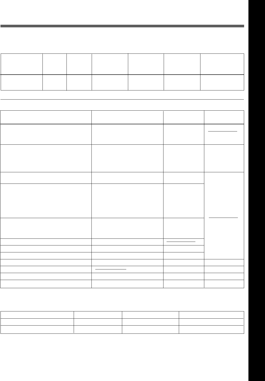
111
Appendix
Appendix
Input/output
impedance
Send: 150 Ω
Return: 10 kΩ
Signal format
Duty 50 %
NTSC Color/ B & W
PAL
SMPTE/EBU
MIDI standard
Sony 9-pin
Make-point
PS/2
PS/2
USB
RS-232C
Analog RGB
Connector type (load impedance)
×1, BNC type (75 Ω)
×1, BNC type (75 Ω)
×2, BNC type (loop through) (75 Ω)
XLR-3-32, Balanced/XLR-3-31,
Balanced
DIN 5-pin, female
D-sub 9-pin, female
Mini DIN 8-pin, female
Phone jack
Mini DIN 6-pin, female
Mini DIN 6-pin, female
D-sub 9-pin, male
D-sub high density 15-pin, female
Analog insertion signal
Number of
inputs/
outputs
×12
Number of
channels
×12
Connector type
1/4 ” TRS,
Unbalanced
Reference level
(load
impedance)
0 dBu (10 kΩ)
Maximum input/
output level
(load
impedance)
+20 dBu (10 kΩ)
Connector
INSERTION 1 to 12
(send/return)
Control signal input/output
Pin assignment
XLR-3-31/XLR-3-32 connector 2:Hot 3:Cold 1:GND
1/4 ” TRS (Balanced) connector Tip:Hot Ring:Cold Sleeve:GND
1/4 ” TRS (Unbalanced) connector Tip:INSERTION SEND Ring:INSERTION RETURN Sleeve:GND
Connector
REF WORD (with 75 Ω termination switch)
IN
OUT
REF VIDEO
TIME CODE input/output
MIDI
MTC
IN
OUT
THRU
REMOTE
IN
OUT 1, OUT 2
PC PORT
FOOT SW
MOUSE
KEYBOARD
USB
SERIAL
MONITOR
Appendix
Reference level
VB, BB: 1.0
±0.2 Vp-p
Composite: 0.2 V
to 5 Vp-p
When 88.2 kHz or 96 kHz is selected as a sampling
frequency, some functions are limited.
For detailed information, see page 76.
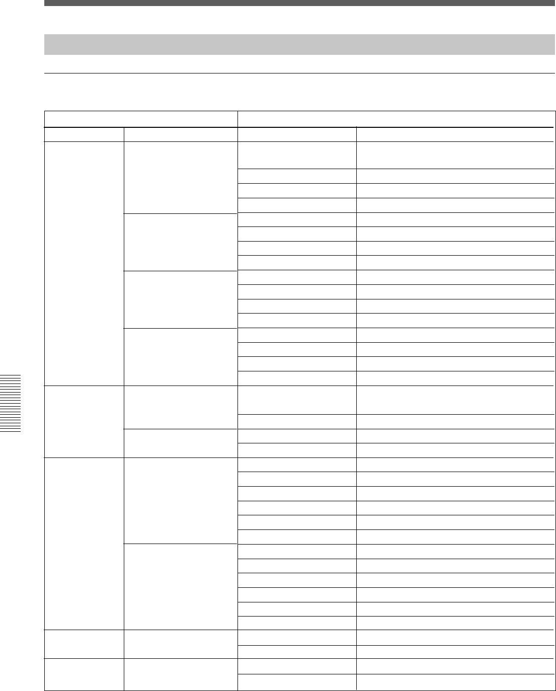
112
Appendix
Appendix
Specifications
Audio Characteristics
Signal processing characteristics
Characteristics Specification
Signal processing
Equalizer
Filter
Dynamics
Oscillator
Level meter
High frequency range
High-mid frequency range
Low-mid frequency range
Low frequency range
High cut filter
Low cut filter
Compressor/Ducking
Expander/Gate
32/40 bit floating point
Frequency range
Response adjustable range
Q
Type
Frequency range
Response adjustable range
Q
Type
Frequency range
Response adjustable range
Q
Type
Frequency range
Response adjustable range
Q
Type
Cut-off frequency
Roll-off characteristics
Cut-off frequency
Roll-off characteristics
Threshold
Attack time
Release time
Ratio
Range
Hold time
Threshold
Attack time
Release time
Ratio
Range
Hold time
Frequency
Output level
Indicator
Overload detection
1fs 1): 622 Hz to 19.9 kHz (61 points)
2fs 2): 622 Hz to 39.8 kHz (73 points)
±20 dB (128 points, 0.25 to 0.5 dB step)
0.5 to 16 (63 points)
Shelving/Peaking switchable
220 Hz to 7.0 kHz (61 points)
±20 dB (128 points, 0.25 to 0.5 dB step)
0.5 to 16 (63 points)
Peaking
77.8 Hz to 2.5 kHz (61 points)
±20 dB (128 points, 0.25 to 0.5 dB step)
0.5 to 16 (63 points)
Peaking
27.5 Hz to 880 Hz (61 points)
±20 dB (128 points, 0.25 to 0.5 dB step)
0.5 to 16 (63 points)
Shelving/Peaking switchable
1fs 1): 1.48 kHz to 22.35 kHz (48 points)
2fs 2): 1.48 kHz to 42.2 kHz (59 points)
12 dB/Octave
27.5 Hz to 415 Hz (48 points)
12 dB/Octave
0 dB to - 60 dB (106 points)
20 µs to 1 s (121 points)
31.6 ms to 50.1 s (97 points)
1 : 1 to ∞ : 1 (31 points)
AUTO, 0 dB to 15 dB (0.25 dB step)
20 µs to 1 s (121 points)
0 dB to -80 dB (126 points)
20 µs to 1 s (121 points)
31.6 ms to 50.1 s (97 points)
1 : 1 to 1 : 10 (31 points)
0 dB to 60 dB (1 dB step)
20 µs to 1 s (121 points)
20 Hz to 20 kHz (28 points)
- ∞ to 10 dBFS (31 points)
20 segment LED
Full-scale 1 word
1): 1fs: 44.1/48 kHz
2): 2fs: 88.2/96 kHz
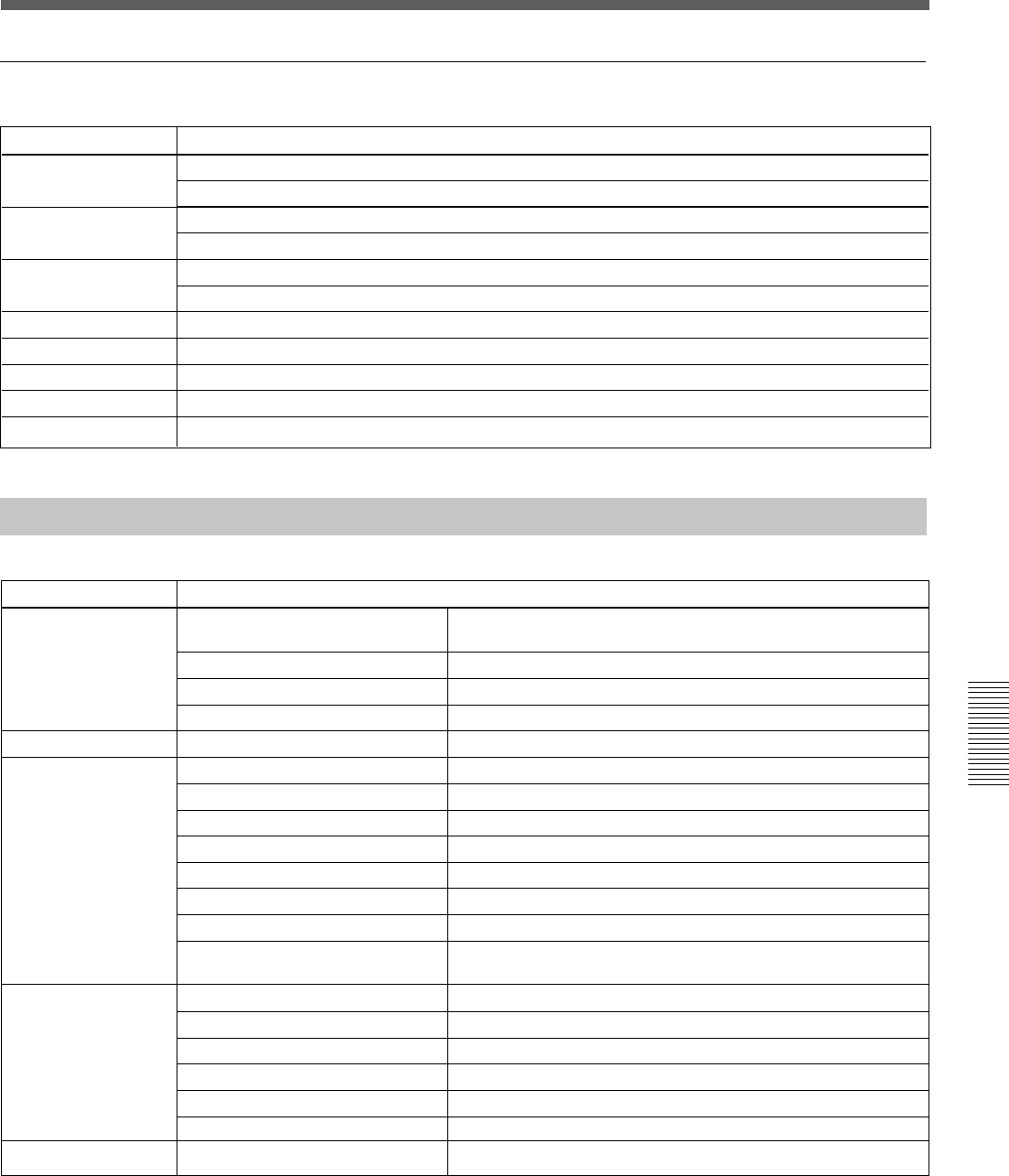
113
Appendix
Appendix
Another audio characteristics
Characteristics
Frequency response
Harmonic distortion
Noise level
Crosstalk
Dynamic range
A to D converter
D to A converter
Total delay
Specifications
Line input (LINE IN to PGM OUT) 20 Hz to 20 kHz, ±0.2 dB
Mic input (MIC IN to PGM OUT) 20 Hz to 20 kHz, ±0.3 dB
Line input (LINE IN to PGM OUT) 0.01 %, at + 4 dBs, 1 kHz
Mic input (MIC IN to PGM OUT) 0.1 %, at - 60 dBs, 1 kHz
Mic input -104 dBu, 600 Ω terminated (-80 dBµ, 4 dB standard)
Mic input -126 dBu, 150 Ω terminated
Between input and output channels 90 dB at 1 kHz
Line input (LINE IN to PGM OUT) 104 dB
24-bit, ×128 oversampling
24-bit, ×128 oversampling
2.5 ms (Between LINE IN and PGM OUT)Fs = 48 kHz
Automation Function
Item
Title
Title configuration
Snapshot automation
Dynamic automation
Fader resolution
Contents
Contents of title
Number of title configuration
Number of snapshot automation
Storage
Contents of title configuration
Number of snapshots
Number of MIDI events
Number of cue points
Number of events per cue point
Size of snapshot
Memory
Time accuracy of cue linked event
Contents of snapshots
Buffer size
Number of temporary buffers
Event size
Memory
Time accuracy
Contents of dynamic automation a)
Title configuration, snapshot automation, mix (saved dynamic
automation)
×1
×1
Built-in flash memory or floppy disk
FS, Initial snapshot, Timecode mode, Output
99 max.
99 max.
99 max.
1
8 kbyte/snapshot
Dynamic RAM a)
± 2 frames
Input router, delay, phase, trimming, input mode, filter, equalizer,
dynamics, pan, assign, cut, fader, AUX
1 M byte
2 (A and B)
12 bytes/effective frame (min)
Dynamic RAM a)
± 2 frames
Filter, equalizer, dynamics, pan, assign, cut, fader, AUX
10-bit (1024 steps)
a) When you turn off the power of the unit, or start the unit without performing KEEP operation, the automation
data will be cleared.
114
Appendix
Appendix
Others
Power requirements DMX-R100 (UC): AC120 V,
60 Hz
DMX-R100 (CE): AC 220 to
240 V -, 50/60 Hz
Power consumption 200 W
Peak inrush current
(1) Power ON, current probe method:
50 A (240V)
(2) Hot switching inrush current,
measured in accordance with
European standard EN55103-1: 10 A
(230V)
Appel de courant de crête
(1) Mise sous tension (ON), méthode de
sondage du courant: 50 A (240V)
(2) Mesuré conformément à la norme
européenne EN55103-1 : 10 A
(230V)
Spitzenstrom
(1) Einschaltstrom, Stromsonde: 50 A
(240V)
(2) Gemessen in EN55103-1: 10 A
(230V)
Dimensions 1140 x 240 x 677 (w/h/d) mm
(45 x 9 1⁄2 x 26 3⁄4 inches)
Mass 55 kg (121 lb 4 oz)
Operating temperature
5°C to 35°C (41°F to 95°F)
Storage temperature -20 °C to 60°C (-4°F to 140°F)
Supplied Accessories
Power supply cord (1)
Operating Instructions (1)
Optional Accessories
DMBK-R101 8CH Analog Line In Board
DMBK-R102 8CH Analog Line Out Board
DMBK-R103 8CH AES/EBU DIO Board
DMBK-R104 8CH Sampling Rate Converter DI
Board
DMBK-R105 8CH Insertion board
DMBK-R106 Interface Board for ADAT
DMBK-R107 Interface Board for TDIF
Design and specifications are subject to change
without notice.

115
Appendix
Appendix
MIDI
MIDI Implementation Chart
Function Transmitted Recognized Remarks
Basic: At power on 1 to 16, OFF 1 to 16, OFF Memorized after the power off.
Channel: Assignable 1 to 16, OFF 1 to 16, OFF
Mode: At power on ×OMNI ON/OFF Memorized after the power off.
Message ××
Altered ********** ×
Note ××
Number True voice ********** ×
Velocity: Note ON ××
Note OFF ××
After touch Keys ××
Channels ××
Pitch Bend ××
Control change 0-102 aaRefer to the control change table.
Assignable 0/127
Program change aa
Assignable
System Exclusive aaBulk damp
System common: Song position ××
Song select ××
Tune ××
Real time: Clock ××
Command ××
Others Local ON/OFF ××
All note OFF ××
Active sensing ××
Reset ××
Remarks:
Mode 1: OMNI ON, POLI
Mode 2: OMNI OFF, MONO
Mode 3: OMNI OFF, POLI
Mode 4: OMNI OFF, MONO
a: Yes
×: No

116
Appendix
Appendix
MIDI
Control Change Table
Parameter Mode 1 Mode 2
change No. Function Function
0—— ——
1 CH1 Fader CH1 Fader
2 CH2 Fader CH2 Fader
3 CH3 Fader CH3 Fader
4 CH4 Fader CH4 Fader
5 CH5 Fader CH5 Fader
6 CH6 Fader CH6 Fader
7 CH7 Fader CH7 Fader
8 CH8 Fader CH8 Fader
9 CH9 Fader CH9 Fader
10 CH10 Fader CH10 Fader
11 CH11 Fader CH11 Fader
12 CH12 Fader CH12 Fader
13 CH13 Fader CH13 Fader
14 CH14 Fader CH14 Fader
15 CH15 Fader CH15 Fader
16 CH16 Fader CH16 Fader
17 CH17 Fader CH17 Fade
18 CH18 Fader CH18 Fader
19 CH19 Fader CH19 Fader
20 CH20 Fader CH20 Fader
21 CH21 Fader CH21 Fader
22 CH22 Fader CH22 Fader
23 CH23 Fader CH23 Fader
24 CH24 Fader CH24 Fader
25 CH25 Fader MTR1 MASTER Fader
26 CH26 Fader MTR2 MASTER Fader
27 CH27 Fader MTR3 MASTER Fader
28 CH28 Fader MTR4 MASTER Fader
29 CH29 Fader MTR5 MASTER Fader
30 CH30 Fader MTR6 MASTER Fader
31 CH31 Fader MTR7 MASTER Fader
32 —— MTR8 MASTER Fader
33 CH32 Fader AUX1 MASTER Fader
34 CH33 Fader AUX2 MASTER Fade
35 CH34 Fader AUX3 MASTER Fader
36 CH35 Fader AUX4 MASTER Fader
37 CH36 Fader AUX5 MASTER Fader
38 CH37 Fader AUX6 MASTER Fade
39 CH38 Fader AUX7 MASTER Fader
Parameter Mode 1 Mode 2
change No. Function Function
40 CH39 Fader AUX8 MASTER Fader
41 CH40 Fader AUX RET1 Fader
42 CH41 Fader AUX RET2 Fade
43 CH42 Fader AUX RET3 Fader
44 CH43 Fader AUX RET4 Fader
45 CH44 Fader AUX RET5 Fader
46 CH45 Fader AUX RET6 Fader
47 CH46 Fader AUX RET7 Fader
48 CH47 Fader AUX RET8 Fader
49 CH48 Fader PGM MASTER Fader
50 MTR1 MASTER Fader CH1 PAN
51 MTR2 MASTER Fader CH2 PAN
52 MTR3 MASTER Fader CH3 PAN
53 MTR4 MASTER Fader CH4 PAN
54 MTR5 MASTER Fader CH5 PAN
55 MTR6 MASTER Fader CH6 PAN
56 MTR7 MASTER Fader CH7 PAN
57 MTR8 MASTER Fader CH8 PAN
58 AUX1 MASTER Fader CH9 PAN
59 AUX2 MASTER Fader CH10 PAN
60 AUX3 MASTER Fader CH11 PAN
61 AUX4 MASTER Fader CH12 PAN
62 AUX5 MASTER Fader CH13 PAN
63 AUX6 MASTER Fader CH14 PAN
64 AUX7 MASTER Fader CH15 PAN
65 AUX8 MASTER Fader CH16 PAN
66 AUX RET1 Fader CH17 PAN
67 AUX RET2 Fader CH18 PAN
68 AUX RET3 Fader CH19 PAN
69 AUX RET4 Fader CH20 PAN
70 AUX RET5 Fader CH21 PAN
71 AUX RET6 Fader CH22 PAN
72 AUX RET7 Fader CH23 PAN
73 AUX RET8 Fader CH24 PAN
74 PGM MASTER Fader CH1 CUT
75 CH1 PAN CH2 CUT
76 CH2 PAN CH3CUT
77 CH3 PAN CH4 CUT
78 CH4 PAN CH5 CUT
79 CH5 PAN CH6 CUT
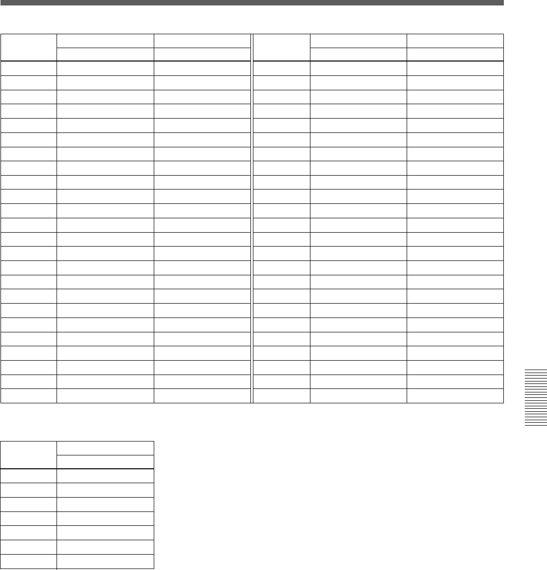
117
Appendix
Appendix
Parameter Mode 1 Mode 2
change No. Function Function
80 CH6 PAN CH7 CUT
81 CH7 PAN CH8 CUT
82 CH8 PAN CH9 CUT
83 CH9 PAN CH10 CUT
84 CH10 PAN CH11 CUT
85 CH11 PAN CH12 CUT
86 CH12 PAN CH13 CUT
87 CH13 PAN CH14 CUT
88 CH14 PAN CH15 CUT
89 CH15 PAN CH16 CUT
90 CH16 PAN CH17 CUT
91 CH17 PAN CH18 CUT
92 CH18 PAN CH19 CUT
93 CH19 PAN CH20 CUT
94 CH20 PAN CH21 CUT
95 CH21 PAN CH22 CUT
96 CH22 PAN CH23 CUT
97 CH23 PAN CH24 CUT
98 CH24 PAN AUX RET1 CUT
99 CH25 PAN AUX RET2 CUT
100 CH26 PAN AUX RET3 CUT
101 CH27 PAN AUX RET4 CUT
102 CH28 PAN AUX RET5 CUT
103 CH29 PAN AUX RET6 CUT
Parameter Mode 1 Mode 2
change No. Function Function
104 CH30 PAN AUX RET7 CUT
105 CH31 PAN AUX RET8 CUT
106 CH32 PAN CH1 AUX1 SEND
107 CH33 PAN CH2 AUX1 SEND
108 CH34 PAN CH3 AUX1 SEND
109 CH35 PAN CH4 AUX1 SEND
110 CH36 PAN CH5 AUX1 SEND
111 CH37 PAN CH6 AUX1 SEND
112 CH38 PAN CH7 AUX1 SEND
113 CH39 PAN CH8 AUX1 SEND
114 CH40 PAN CH9 AUX1 SEND
115 CH41 PAN CH10 AUX1 SEND
116 CH42 PAN CH11 AUX1 SEND
117 CH43 PAN CH12 AUX1 SEND
118 CH44 PAN CH13 AUX1 SEND
119 CH45 PAN CH14 AUX1 SEND
120 CH46 PAN CH15 AUX1 SEND
121 CH47 PAN CH16 AUX1 SEND
122 CH48 PAN CH17 AUX1 SEND
123 CH48 PAN CH18 AUX1 SEND
124 —— CH19 AUX1 SEND
125 —— CH20 AUX1 SEND
126 —— CH21 AUX1 SEND
127 —— CH22 AUX1 SEND
Parameter Mode 3
change No. Function
0 to 25 Invalid
26 Talkback (PGM)
27 Talkback (AUX)
28 Talkback (MTR)
29 Talkback (STUDIO)
30 Talkback (SLATE)
31 to 127 Invalid

118
Appendix
Appendix
Index
A
Analog head amplifier
Analog head amplifier
panel ............................... 11
Setting operation flow ......... 92
Analog signal
Analog head amplifier
panel ............................... 11
Analog signal connectors .... 31
Selecting the input
connectors....................... 11
Assigning the bus ..................... 58
Assigning the input source ....... 56
Automation
Automation panel ................ 25
Automation status display ... 39
AUTOMATION window .... 68
Dynamic automation ........... 68
Removing channels from the
automation .............. 69, 103
Removing the functions from
the automation ........ 69, 103
Seeing the level of the
automation data stored ... 51
Snapshot automation ........... 64
Updating automation data (in
TRIM mode)................. 100
Writing automation data (in
ABS mode) ..................... 99
Writing dynamic automation
data ................................. 42
AUX bus
AUX SEND section............. 21
AUX SEND window ........... 49
Connectors ..................... 32, 33
Seeing the AUX Send
level ................................ 50
B, C
Basic operation flow ................. 91
Buffer
Buffer A/B ..................... 26, 88
Copying data between Buffer A
and Buffer B ................... 26
Channel
Changing the channel .......... 41
CHANNEL window ............ 43
Copying channel settings..... 14
Seeing the channel status..... 43
Setting.................................. 92
Connection examples.................. 7
Live recording ....................... 9
Music production................... 8
Video post production ........... 7
Control room monitor
Confirming .......................... 92
CR (control room) MONITOR
section............................. 24
MONITOR window ............ 59
Settings ................................ 59
Controlling the external devices
Closed loop/open loop ......... 71
Control signal connectors .... 29
MACHINE CONTROL
window ........................... 70
Transport control keys ......... 27
Cue
Changing a cue point ........... 97
Changing a name ................. 98
Cue list................................. 66
CUE window ....................... 66
Deleting ............................... 98
Initial cue ................. 67, 90, 96
Setting.................................. 96
Storing a cue point............... 96
Sorting the cue list ............... 67
Cut
AUDIO FADER GROUPING
window ........................... 52
Clearing the group ............... 53
CUT button .......................... 13
Fine adjustment of
the cut point .................. 102
Setting the cut group............ 54
D
Default setting of the unit ......... 90
Dialog messages ..................... 107
Digital signal
Adjusting the digital input
signal .............................. 18
Digital signal connectors ..... 33
INPUT section on the unit ... 18
I/O STATUS window.......... 81
Drop in/drop out ....................... 40
Dynamic automation
AUTOMATION window .... 68
Writing data ......................... 42
Dynamics
Dynamics characteristics
display ............................ 47
DYNAMICS section
in the unit........................ 18
DYNAMICS window .......... 47
E, F, G, I, K
Equalizer
EQUALIZER/FILTER
window ........................... 46
Equalizer section ................. 20
Setting the equalizer ............ 46
Fader
AUDIO FADER GROUPING
window ........................... 52
AUDIO FADER window .... 51
Channel fader ...................... 14
Clearing the group ............... 54
Fader grouping .................... 52
Fader operations and
its results....................... 100
FADERS section ................. 16
GANG group ....................... 53
Master fader......................... 53
Seeing the fader
level .................... 43, 50, 51
VCA group .......................... 53
Initial cue ...................... 67, 90, 96
Input routing ............................. 56
KEEP .................................. 37, 88
Keyboard
Changing the keyboard
type ................................. 87
KEYBOARD window ......... 86
M
MASTERS button .................... 17
Master meter buttons ................ 22
Master panel ............................. 22

119
Appendix
Appendix
Memory
Dynamic RAM .................... 88
Flash memory ...................... 88
Memory structure ................ 88
Menu
Bottom menu bar ................. 40
Menu structure..................... 36
Menu windows
AUDIO FADER window .... 51
AUDIO INPUT ROUTING
window ........................... 55
AUDIO OUTPUT ROUTING
window ........................... 57
AUDIO OVERVIEW
window ........................... 50
AUTOMATION window .... 68
AUX SEND window ........... 49
CHANNEL window ............ 43
CUE window ....................... 66
DYNAMICS window .......... 47
EQUALIZER/FILTER
window ........................... 46
INPUT/PAN/ASSIGN
window ........................... 44
I/O STATUS window.......... 81
KEYBOARD window ......... 86
MACHINE CONTROL
window ........................... 70
MIDI window ...................... 75
MISC SETUP window ........ 84
MONITOR window ............ 59
OSC/TALKBACK
window ........................... 55
SNAPSHOT window .......... 64
SYNC/TIME CODE
window ........................... 76
TITLE MANAGER
window ........................... 72
Messages................................. 107
MIDI
Control change table.......... 116
MIDI connectors.................. 29
MIDI implement chart ....... 115
MIDI window ...................... 75
Monitoring
CR (control room) MONITOR
section............................. 24
MONITOR window ............ 59
PFL/AFL ............................. 60
STUDIO LS (studio speaker)
section............................. 22
O
Optional boards
DMBK-R101 8CH Analog
Line In Board ................. 34
DMBK-R102 8CH Analog
Line Out Board ............... 34
DMBK-R103 8CH AES/EBU
DIO Board ...................... 34
DMBK-R104 8CH Sampling
Rate Converter DI
Board .............................. 34
DMBK-R105 8CH Insertion
Board .............................. 35
DMBK-R106 Interface Board
for ADAT ....................... 35
DMBK-R107 Interface Board
for TDIF ......................... 35
I/O STATUS window.......... 81
Setting the optional slots ..... 81
Slots for optional boards...... 33
Oscillator
OSC/TALKBACK
window ........................... 62
Setting on the window ......... 62
Output routing .......................... 57
P
PAGEs section .......................... 17
PAGE button on the
window ........................... 50
Pages selectable buttons ...... 17
Pan
INPUT/PAN/ASSIGN
window ........................... 44
Pan control........................... 12
Pan position ......................... 50
PANS section on the unit .... 16
PAN section on the
window ........................... 45
Surround ........................ 45, 85
Parameter
Parameter display section .... 47
Parameter setting panel ....... 17
Setting.................................. 17
PGM
PGM bus section
in the unit........................ 24
Punch in/punch out
AUTOMATION window .. 105
Using the automation
function......................... 104
Using the foot switch......... 105
R, S
READY status .......................... 38
Resetting the input matrix to the
default setting ...................... 56
Resetting the output matrix to the
default setting ...................... 58
Routing input ............................ 56
Routing output .......................... 58
Sampling frequency
Changing ............................. 89
Confirming/changing........... 91
Limitations when setting
88.2 kHz or 96 kHz fs .... 76
PLL status ............................ 77
Selecting .............................. 76
Sync clock ........................... 77
SYNC/TIME CODE
window ........................... 76
Seeing the settings
on the unit ............................ 50
Signal flow.............................. 121
Snapshot
Automation panel ................ 25
Changing a snapshot data
linked with a cue point ... 97
Changing a snapshot name .. 95
Deleting a snapshot ............. 95
Recalling a snapshot ............ 95
Setting.................................. 94
SNAPSHOT buttons............ 26
SNAPSHOT window .......... 64
Storing/updating a snapshot
data ................................. 94
Solo
Enable/disable ..................... 61
Inserting the solo signal into
the monitor signal on the
window ........................... 61
SOLO button ....................... 13
Solo isolate function ............ 61
Solo mode section ............... 23

120
Appendix
Appendix
Source
AUDIO INPUT ROUTING
window ........................... 55
Changing/selecting
the source........................ 44
INPUT/PAN/ASSIGN
window ........................... 44
Routing a source signal to a
channel ........................... 55
Specifications
Analog audio
input/output .................. 110
Audio characteristics ......... 112
Automation function.......... 113
Control signal
input/output .................. 111
Digital audio
input/output .................. 110
Signal processing
characteristics ............... 112
Stereo
STEREO link....................... 44
Using the stereo signal ........ 93
Storing data............................... 92
Studio monitor
Confirming/monitoring ....... 92
MONITOR window ............ 59
Setting.................................. 59
STUDIO LS (studio speaker)
section............................. 22
Surround mode
INPUT/PAN/ASSIGN
window ........................... 44
MSC SETUP window ......... 84
SURROUND PAN section.. 45
T, V, W
Talk-back
OSC/TALKBACK
window ........................... 62
TALKBACK panel.............. 14
Timecode
Confirming/changing........... 91
Selecting the timecode......... 78
SYNC/TIMECODE
window ........................... 76
TC AUTOMATION
buttons ............................ 25
Timecode display window... 26
Timecode input section ....... 26
Title
About title ............................ 89
Current title.......................... 73
KEEP ............................. 37, 88
Initializing ........................... 89
Loading................................ 89
Saving .................................. 89
TITLE menu ........................ 37
TITLE button....................... 37
TITLE MANAGER
window ........................... 72
When turning on the unit ..... 89
Touch panel
Calibrating ........................... 85
Operating the touch panel.... 41
VCA group ............................... 53
Window operation
Changing the channel .......... 41
Operating the touch panel.... 41
Selecting the channel
or source ......................... 41
Selecting the item ................ 41
Setting the function on/off... 41
Setting the write mode......... 42
Write
Write button......................... 12
Write mode .......................... 42
Index
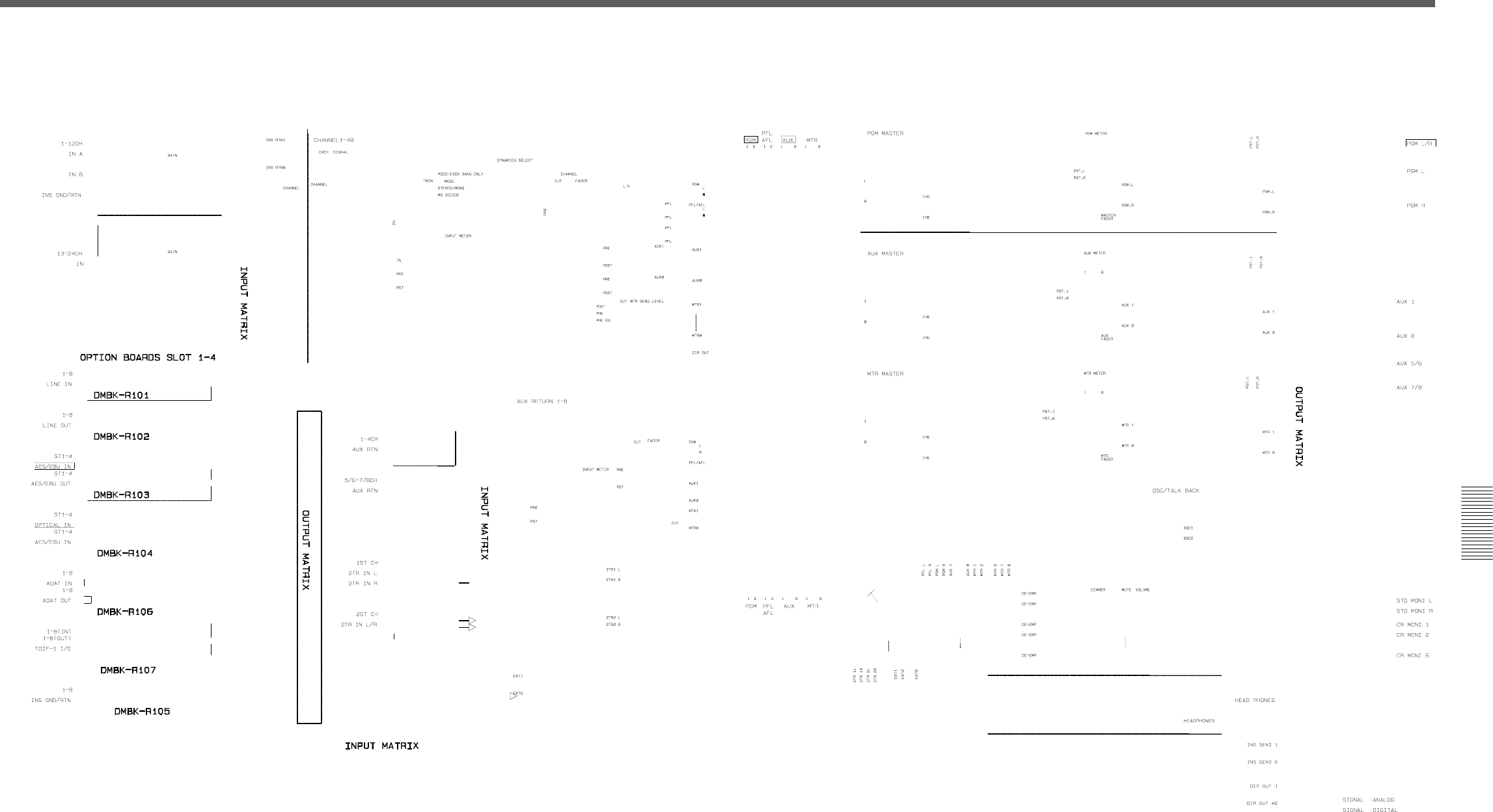
121
Appendix
Appendix
Block Diagram
Fs = 44.1/48 kHz (1 fs)
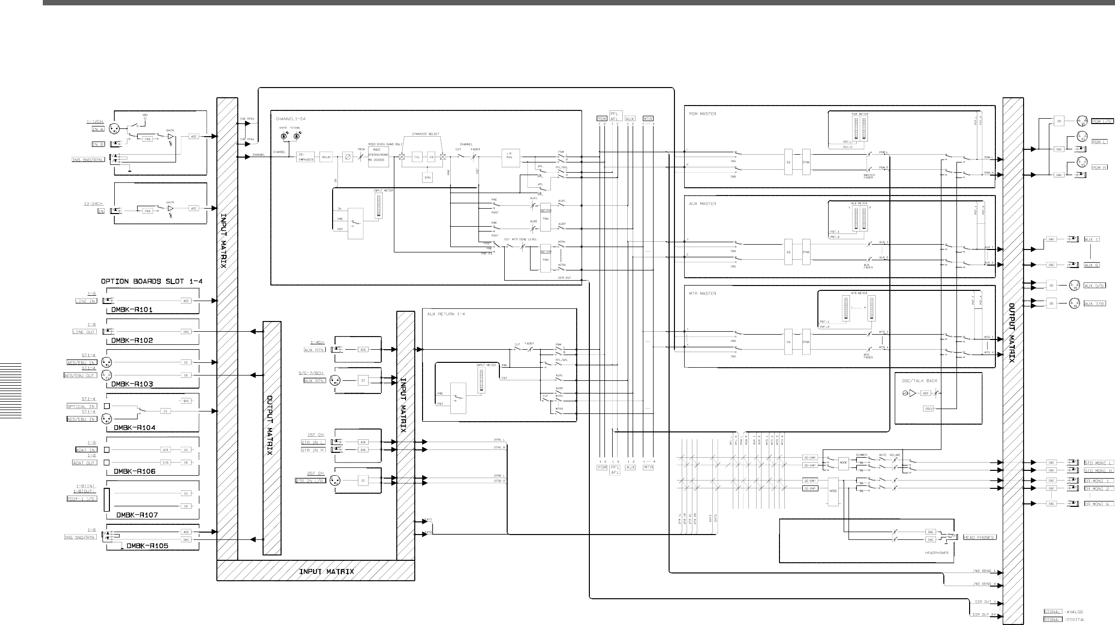
122 Appendix
Appendix
Fs = 88.2/96 kHz (2 fs)
Block Diagram


Sony Corporation Printed in Japan
