Sony Dsr 1800Ap Users Manual 1800A/1800AP
DSR-1800AP to the manual fb921d43-733b-4dc0-9576-fe9ae35823c1
2015-01-23
: Sony Sony-Dsr-1800Ap-Users-Manual-291906 sony-dsr-1800ap-users-manual-291906 sony pdf
Open the PDF directly: View PDF ![]() .
.
Page Count: 112 [warning: Documents this large are best viewed by clicking the View PDF Link!]
- Table of Contents
- Chapter 1 Overview
- Chapter 2 Recording and Playback
- Chapter 3 Convenient Functions for Editing Operation
- Chapter 4 Menu Settings
- Chapter 5 Connections and Settings
- Chapter 6 Maintenance and Troubleshooting
- Appendixes
- Index
DSR-1800A/1800AP
© 2005 Sony Corporation
3-869-571-12 (1)
The supplied CD-ROM includes Operating Instructions
for the DSR-series Digital Video Cassette Recorder or Player
(English, Japanese, French, German, Italian and Spanish versions).
For more details, see “Using the CD-ROM Manual” on page 11.
Digital
Videocassette
Recorder
Operating Instructions
Before operating the unit, please read this manual
thoroughly and retain it for future reference.
2
Owner’s Record
The model and serial numbers are located at the rear.
Record these numbers in the spaces provided below. Refer
to them whenever you call upon your Sony dealer
regarding this product.
Model No. Serial No.
• Read these instructions.
• Keep these instructions.
• Heed all warnings.
• Follow all instructions.
• Do not use this apparatus near water.
• Clean only with dry cloth.
• Do not block any ventilation openings.
Install in accordance with the manufacturer’s
instructions.
• Do not install near any heat sources such as radiators,
heat registers, stoves, or other apparatus (including
amplifiers) that produce heat.
• Do not defeat the safety purpose of the polarized or
grounding-type plug. A polarized plug has two blades
with one wider than the other. A grounding-type plug
has two blades and a third grounding prong. The wide
blade or the third prong are provided for your safety. If
the provided plug does not fit into your outlet, consult an
electrician for replacement of the obsolete outlet.
• Protect the power cord from being walked on or pinched
particularly at plugs, convenience receptacles, and the
point where they exit from the apparatus.
• Only use attachments/accessories specified by the
manufacturer.
• Use only with the cart, stand, tripod, bracket, or table
specified by the manufacturer, or sold with the
apparatus.
When a cart is used, use caution when
moving the cart/apparatus combination to
avoid injury from tip-over.
• Unplug this apparatus during lightning
storms or when unused for long periods of
time.
• Refer all servicing to qualified service
personnel. Servicing is required when the
apparatus has been damaged in any way,
such as power-supply cord or plug is
damaged, liquid has been spilled or objects
have fallen into the apparatus, the
apparatus has been exposed to rain or
moisture, does not operate normally, or has
been dropped.
To prevent fire or shock hazard, do not
expose the unit to rain or moisture.
To avoid electrical shock, do not open the
cabinet. Refer servicing to qualified
personnel only.
THIS APPARATUS MUST BE EARTHED.
CAUTION
The apparatus shall not be exposed to dripping or
splashing. No objects filled with liquids, such as vases,
shall be placed on the apparatus.
The unit is not disconnected from the AC power source
(mains) as long as it is connected to the wall outlet, even if
the unit itself has been turned off.
Television programs, films, video tapes and other
materials may be copyrighted.
Unauthorized recording of such material may be contrary
to the provisions of the copyright laws.
Important Safety Instructions
This symbol is intended to alert the user to
the presence of uninsulated “dangerous
voltage” within the product’s enclosure
that may be of sufficient magnitude to
constitute a risk of electric shock to
persons.
This symbol is intended to alert the user to
the presence of important operating and
maintenance (servicing) instructions in
the literature accompanying the
appliance.
WARNING

3
WARNING: THIS WARNING IS APPLICABLE FOR
USA ONLY.
Using this unit at a voltage other than 120 V may require
the use of a different line cord or attachment plug, or both.
To reduce the risk of fire or electric shock, refer servicing
to qualified service personnel.
For the customers in the USA (DSR-1800A only)
This equipment has been tested and found to comply with
the limits for a Class A digital device, pursuant to Part 15
of the FCC Rules. These limits are designed to provide
reasonable protection against harmful interference when
the equipment is operated in a commercial environment.
This equipment generates, uses, and can radiate radio
frequency energy and, if not installed and used in
accordance with the instruction manual, may cause
harmful interference to radio communications. Operation
of this equipment in a residential area is likely to cause
harmful interference in which case the user will be
required to correct the interference at his own expense.
You are cautioned that any changes or modifications not
expressly approved in this manual could void your
authority to operate this equipment.
All interface cables used to connect peripherals must be
shielded in order to comply with the limits for a digital
device pursuant to Subpart B of Part 15 of FCC Rules.
WARNING
Excessive sound pressure from earphones and headphones
can cause hearing loss.
In order to use this product safely, avoid prolonged
listening at excessive sound pressure levels.
For the customers in Europe (DSR-1800AP only)
This product with the CE marking complies with both the
EMC Directive and the Low Voltage Directive issued by
the Commission of the European Community.
Compliance with these directives implies conformity to
the following European standards:
• EN60065: Product Safety
• EN55103-1: Electromagnetic Interference(Emission)
• EN55103-2: Electromagnetic Susceptibility(Immunity)
This product is intended for use in the following
Electromagnetic Environments:
E1 (residential), E2 (commercial and light industrial), E3
(urban outdoors), E4 (controlled EMC environment, ex.
TV studio)
The manufacturer of this product is Sony Corporation, 1-
7-1 Konan, Minato-ku, Tokyo, Japan.
The Authorized Representative for EMC and product
safety is Sony Deutschland GmbH, Hedelfinger Strasse
61, 70327 Stuttgart, Germany. For any service or
guarantee matters please refer to the addresses given in
separate service or guarantee documents.
For the customers in Taiwan only

4
Afin de réduire les risques d’incendie ou
d’électrocution, ne pas exposer cet
appareil à la pluie ou à l’humidité.
Afin d’écarter tout risque d’électrocution,
garder le coffret fermé. Ne confier l’entretien
de l’appareil qu’à un personnel qualifié.
CET APPAREIL DOIT ÊTRE RELIÉ À LA
TERRE.
ATTENTION
Eviter d’exposer l’appareil à un égouttement ou à des
éclaboussures. Ne placer aucun objet rempli de liquide,
comme un vase, sur l’appareil.
Cet appareil n’est pas déconnecté de la source
d’alimentation secteur tant qu’il est raccordé à la prise
murale, même si l’appareil lui-même a été mis hors
tension.
Des programmes de télévision, films, bandes vidéo et
autres peuvent être protégés par des droits d’auteur.
L’enregistrement non autorisé de tels matériaux risque de
constituer une violation de ces droits d’auteur.
AVERTISSEMENT
Une pression acoustique excessive en provenance des
écouteurs ou du casque peut provoquer une baisse de
l’acuité auditive.
Pour utiliser ce produit en toute sécurité, évitez l’écoute
prolongée à des pressions sonores excessives.
Pour les clients européens
(DSR-1800AP seulement)
Ce produit portant la marque CE est conforme à la fois à la
Directive sur la compatibilité électromagnétique (EMC) et
à la Directive sur les basses tensions émises par la
Commission de la Communauté Européenne.
La conformité à ces directives implique la conformité aux
normes européennes suivantes :
• EN60065: Sécurité des produits
• EN55103-1: Interférences électromagnétiques (émission)
• EN55103-2: Sensibilité électromagnétique (immunité)
Ce produit est prévu pour être utilisé dans les
environnements électromagnétiques suivants :
E1 (résidentiel), E2 (commercial et industrie légère), E3
(urbain extérieur) et E4 (environnement EMC contrôlé, ex.
studio de télévision).
Le fabricant de ce produit est Sony Corporation, 1-7-1
Konan, Minato-ku, Tokyo, Japon.
Le représentant autorisé pour EMC et la sécurité des
produits est Sony Deutschland GmbH, Hedelfinger Strasse
61, 70327 Stuttgart, Allemagne. Pour toute question
concernant le service ou la garantie, veuillez consulter les
adresses indiquées dans les documents de service ou de
garantie séparés.
Um die Gefahr von Bränden oder
elektrischen Schlägen zu verringern, darf
dieses Gerät nicht Regen oder
Feuchtigkeit ausgesetzt werden.
Um einen elektrischen Schlag zu
vermeiden, darf das Gehäuse nicht geöffnet
werden. Überlassen Sie Wartungsarbeiten
stets nur qualifiziertem Fachpersonal.
DIESES GERÄT MUSS GEERDET WERDEN.
ACHTUNG
Das Gerät ist nicht tropf- und spritzwassergeschützt. Es
dürfen keine mit Flüssigkeiten gefüllten Gegenstände, z.
B. Vasen, darauf abgestellt werden.
Solange das Netzkabel an eine Netzsteckdose
angeschlossen ist, bleibt das Gerät auch im
ausgeschalteten Zustand mit dem Strommetz verbunden.
Fernsehprogramme, Filme, Videobänder usw. können
urheberrechtlich geschützt sein. Unerlaubtes Aufnehmen
solcher Materialien verstößt gegen das Urheberrecht.
WARNUNG
Zu hoher Schalldruck von Ohrhörern und Kopfhörern
kann Gehörschäden verursachen.
Um dieses Produkt sicher zu verwenden, vermeiden Sie
längeres Hören bei sehr hohen Schalldruckpegeln.
Für Kunden in Europa (Nur DSR-1800AP)
Dieses Produkt besitzt die CE-Kennzeichnung und erfüllt
die EMV-Richtlinie sowie die Niederspannungsrichtlinie
der EG-Kommission.
Angewandte Normen:
• EN60065: Sicherheitsbestimmungen
• EN55103-1: Elektromagnetische Verträglichkeit
(Störaussendung)
• EN55103-2: Elektromagnetische Verträglichkeit
(Störfestigkeit)
AVERTISSEMENT
WARNUNG

5
Für die folgenden elektromagnetischen Umgebungen:
E1 (Wohnbereich), E2 (kommerzieller und in
beschränktem Maße industrieller Bereich), E3
(Stadtbereich im Freien) und E4 (kontrollierter EMV-
Bereich, z.B. Fernsehstudio).
Der Hersteller dieses Produkts ist Sony Corporation, 1-7-1
Konan, Minato-ku, Tokyo, Japan.
Der autorisierte Repräsentant für EMV und
Produktsicherheit ist Sony Deutschland GmbH,
Hedelfinger Strasse 61, 70327 Stuttgart, Deutschland. Bei
jeglichen Angelegenheiten in Bezug auf Kundendienst
oder Garantie wenden Sie sich bitte an die in den separaten
Kundendienst- oder Garantiedokumenten aufgeführten
Anschriften.
Per ridurre il rischio di incendi o scosse
elettriche, non esporre questo apparato
alla pioggia o all’umidità.
Per evitare scosse elettriche, non aprire
l’involucro. Per l’assistenza rivolgersi
unicamente a personale qualificato.
QUESTO APPARECCHIO DEVE ESSERE
MESSO A TERRA.
ATTENZIONE
L’apparecchio non deve essere esposto a gocciolamenti o
spruzzi. Non collocare sull’apparecchio oggetti contenenti
liquidi, come ad esempio vasi di fiori.
AVVERTIMENTO
L’apparecchio non è scollegato dalla fonte di
alimentazione CA (corrente di rete) fintanto che è
collegato ad una presa di corrente, anche se l’apparecchio
stesso è stato spento.
Programmi televisivi, film, videonastri e altro materiale
possono essere tutelati dai diritti d’autore.
Registrazioni non autorizzate di tali materiali possono
infrangere la legge sui diritti d’autore.
AVVERTENZA
Un’eccessiva pressione sonora da auricolari e cuffie può
causare la perdita dell’udito.
Per usare questo prodotto in maniera sicura, evitare
l’ascolto prolungato a livelli eccessivi di pressione sonora.
Per i clienti in Europa (DSR-1800AP soltanto)
Questo prodotto recante il marchio CE è conforme sia alla
direttiva sulla compatibilità elettromagnetica (EMC) che
alla direttiva sulle basse tensioni emesse dalla
Commissione della Comunità Europea.
La conformità a queste direttive implica la conformità alle
seguenti normative europee:
• EN60065: Sicurezza dei prodotti
• EN55103-1: Interferenza elettromagnetica (Emissione)
• EN55103-2: Sensibilità ai disturbi elettromagnetici
(Immunità)
Questo prodotto è destinato all’uso nei seguenti ambienti
elettromagnetici:
E1 (residenziali), E2 (commerciali e industriali leggeri),
E3 (esterni urbani) e E4 (ambienti EMC controllati, ad
esempio studi televisivi).
1. Für Ihren privat genutzten Videorecoder muß eine
Fernseh-Rundfunk-Genehmigung beantragt
werden, sofern nicht bereits eine Genehmigung für
ein Fernsehgerät desselben Haushaltes vorliegt. Im
geschäftlichen Bereich ist jeder einzelne
Videorecorder anmelde- und gebührenpflichtig.
(Auskunft ggf. bei der GEZ oder den
Rundfunkanstalten.)
2. Im privaten Bereich ist die Aufzeichnung von
urheberrechtlich geschützten Werken auf Bild-
und Tonträger gestattet. Die entsprechenden
Urheber-Vergütungen sind im Kaufpreis des
Gerätes enthalten. Öffentliche Wiedergabe oder
Verbreitung von mitgeschnittenen
Fernsehsendungen ist ohne Erlaubnis nicht
zulässig, verpflichtet zu Schadenersatz und ist
gegebenenfalls strafbar.
3. Im Rahmen der Regelung des §47 des
Urheberrechtsgesetzes sind Aufzeichnungen von
Schulfernsehprogrammen gestattet. Mitschnitte
von Schulfunksendungen dürfen jedoch nur für
den Unterricht verwendet werden und sind
spätestens am Ende des laufenden Schuljahres zu
löschen.
ATTENZIONE

6
Il fabbricante di questo prodotto è la Sony Corporation, 1-
7-1 Konan, Minato-ku, Tokyo, Giappone.
La rappresentanza autorizzata per EMC e la sicurezza dei
prodotti è la Sony Deutschland GmbH, Hedelfinger
Strasse 61, 70327 Stoccarda, Germania. Per qualsiasi
questione riguardante l’assistenza o la garanzia, si prega di
rivolgersi agli indirizzi riportati nei documenti
sull’assistenza o sulla garanzia a parte.
Para reducir el riesgo de electrocución, no
exponga este aparato a la lluvia ni a la
humedad.
Para evitar descargas eléctricas, no abra el
aparato. Solicite asistencia técnica
únicamente a personal especializado.
ESTE APARATO DEBE CONECTARSE A
TIERRA.
PRECAUCIÓN
No se debe exponer la unidad a goteos o salpicaduras.
Tampoco se deben colocar sobre la misma objetos llenos
de líquido, tales como un florero.
La unidad no queda desconectada de la alimentación
eléctrica siempre que esté conectado al tomacorriente
incluso aunque se desconecte el interruptor principal.
Los programas de televisión, las películas, las cintas de
vídeo y material similar pueden estar protegidos por las
leyes de copyright.
La grabación no autorizada de dicho material puede ir en
contra de lo establecido por las leyes de copyright.
ADVERTENCIA
Una excesiva presión de sonido de los auriculares y cascos
auriculares puede provocar una pérdida de percepción de
sus oídos.
Para utilizar este producto con seguridad, no escuche
durante mucho tiempo con niveles de presión de sonido
excesivos.
Para los clientes de Europa (DSR-1800AP sólo)
Este producto con marcado CE cumple con las directivas
de compatibilidad electromagnética y baja tensión de la
Comisión Europea.
El cumplimiento de estas directivas implica la
conformidad con los siguientes estándares europeos:
• EN60065: Seguridad del producto
• EN55103-1: Interferencia electromagnética (Emisión)
• EN55103-2: Susceptibilidad electromagnética
(Inmunidad)
Este producto está ha sido diseñado para utilizarse en los
entornos electromagnéticos siguientes:
E1 (zona residencial), E2 (zona comercial e industrial
ligera), E3 (exteriores urbanos), y E4 (entorno con EMC
controlada, p. ej., estudio de televisión).
El fabricante de este producto es Sony Corporation, con
dirección en 1-7-1 Konan, Minato-ku, Tokio, Japón.
El Representante autorizado para EMC y seguridad del
producto es Sony Deutschland GmbH, Hedelfinger Strasse
61, 70327 Stuttgart, Alemania. Para asuntos relacionados
con el servicio y la garantía, consulte las direcciones
entregadas por separado para los documentos de servicio o
garantía.
ADVERTENCIA

7
Table of Contents
Table of Contents
Chapter 1 Overview
Features................................................................................. 9
DVCAM Format ....................................................................... 9
A Wealth of Interfaces ............................................................ 10
Facilities for High-Efficiency Editing..................................... 10
Other Features ......................................................................... 10
Optional Accessories............................................................... 11
Using the CD-ROM Manual................................................11
CD-ROM System Requirements............................................. 11
Preparations............................................................................. 11
Reading the CD-ROM Manual ............................................... 11
Location and Function of Parts.........................................13
Front Panel .............................................................................. 13
Rear Panel ............................................................................... 21
Chapter 2 Recording and Playback
Usable Cassettes................................................................27
Inserting and Ejecting Cassettes ............................................. 29
Recording............................................................................ 31
Settings for Recording ............................................................ 31
Recording Procedure............................................................... 34
Playback ..............................................................................37
Settings for Playback .............................................................. 37
Playback Procedure................................................................. 38
Repeat Playback—Automatic Cyclical Playback................... 40
Setting Points A and B for Repeat Playback........................... 40
Cuing Up to Any Desired Position Set as Point A or B.......... 45
Chapter 3 Convenient Functions for Editing Operation
Setting the Time Data......................................................... 47
Displaying Time Data and Operation Mode Indications ........ 47
Using the Internal Time Code Generator................................ 49
Synchronizing Internal and External Time Codes .................. 50
Rerecording the Time Code—TC Insert Function.................. 51
High-Speed and Low-Speed Search—Quickly and
Accurately Determining Editing Points .....................53
Search Operations via External Equipment ............................ 53
Search Operations on This Unit.............................................. 53
Digitally Dubbing Signals in DVCAM Format...................55

8Table of Contents
Chapter 4 Menu Settings
Menu Organization ............................................................. 59
Menu Contents.................................................................... 62
Setup Menu ............................................................................. 62
Auto Mode (AUTO FUNCTION) Execution Menu............... 75
Changing Menu Settings ...................................................76
Buttons Used to Change Settings............................................ 76
Changing the Settings of Basic Items ..................................... 76
Displaying Enhanced Items .................................................... 78
Changing the Settings of Enhanced Items .............................. 78
Returning Menu Settings to Their Factory Default Settings... 79
Displaying Supplementary Status Information................80
Chapter 5 Connections and Settings
Connections for a Digital Non-Linear Editing System ....83
Connections for a Cut Editing System ............................. 85
Connections for an A/B Roll Editing System...................86
Connections for Analog Recording ..................................91
Adjusting the Sync and Subcarrier Phases .....................92
Chapter 6 Maintenance and Troubleshooting
Maintenance........................................................................ 95
Condensation........................................................................... 95
Regular Checks ....................................................................... 95
Head Cleaning......................................................................... 97
Troubleshooting .................................................................98
Error Messages...................................................................... 100
Alarm Messages.................................................................... 100
Appendixes
Precautions....................................................................... 103
Specifications ...................................................................104
Glossary ............................................................................107
Index ..................................................................................109

9
Features
Chapter 1
Overview
Features
The DSR-1800A/1800AP is a 1/4-inch digital video
cassette recorder using the DVCAM digital recording
format. It achieves stable, superb picture quality by
digitally processing video signals separated into color
difference signals and luminance signals (component
method).
The unit is equipped with a variety of functions needed for
videocassette recorders and players used in professional
digital video editing systems.
The unit is also equipped with an i.LINK interface, thus
enabling simple connection with a nonlinear editing*
system supporting DV format.
Furthermore, the unit is equipped with a full-fledged
analog interface to support hybrid systems that combine
conventional analog equipment with digital equipment.
* Non-linear editing: This is an editing method that uses video and audio
signals digitally encoded and recorded on a hard disk as digital data. When
compared with conventional (linear) editing methods, non-linear editing
offers vastly improved efficiency in editing operations, for example, by
eliminating tape transport time.
The main features of the unit are described in the
following.
DVCAM Format
DVCAM is based on the consumer DV format, which uses
the 4:1:1 component digital format, and provides a 1/4-inch
digital recording format for professional use.
High picture quality, high stability
Video signals are separated into color difference signals
and luminance signals, which are encoded and compressed
to one-fifth size before being recorded to ensure stable and
superb picture quality.
Because the recording is digital, multi-generation dubbing
can be performed with virtually no deterioration of quality.
Wide track pitch
The recording track pitch is 15 µm, fully 50 percent wider
than the 10-µm track pitch of the DV format. Thanks to this
feature, the DVCAM format sufficiently meets the
reliability and precision requirements of professional
editing.
High-quality PCM digital audio
PCM recording makes for a wide dynamic range and a
high signal-to-noise ratio, thereby enhancing sound
quality.
There are two recording modes: 2-channel mode (48-kHz
sampling and 16-bit quantization), which offers sound
quality equivalent to the DAT (Digital Audio Tape)
format, or 4-channel mode (32-kHz sampling and 12-bit
quantization).
Playback compatibility with DV and
DVCPRO formats
A DV cassette recorded on a DV format VCR (excluding
the tapes recorded in LP mode) as well as a DVCPRO
(25M) format recorded cassette can be played back on this
unit.
Note
When playing back a tape recorded in DVCPRO (25M)
format, the i.LINK output (see “Digital interfaces” on
page 10) of this unit is subjected to muting. Furthermore,
it is not possible to play back the cue-audio track of the
tape.

10 Features
Chapter 1 Overview
Support for three cassette sizes
There are two sizes of DVCAM cassette: standard and
mini. You can use either size with this unit.
The unit also accepts L and M sizes of DVCPRO cassette.
• When a cassette is inserted, the reel mechanism of the
unit automatically adjusts to the size of the inserted
cassette.
• The capacity of a standard cassette is 184 minutes of
recording/playback, and that of a mini cassette is 40
minutes.
A Wealth of Interfaces
Digital interfaces
i.LINK (DV)*: The unit can input and output digital video
and audio signals in DV format.
* i.LINK and are trademarks and indicate that this product is in agreement
with IEEE1394-1995 specifications and their revisions.
SDI (serial digital interface)/AES/EBU (optional
DSBK-1801 SDI/AES/EBU Input/Output Board):
When the unit is fitted with the optional DSBK-1801
board, it can input and output D1 (component) format
digital video and audio signals and also AES/EBU-
format digital audio signals.
Analog interfaces
The unit also comes with analog interfaces enabling it to be
connected to analog video and audio equipment.
Analog video: These interfaces include a component
interface, composite interface, and S-video interface.
Analog audio: Four channels each of input and output are
provided. It is also possible to connect a microphone to
the unit.
Facilities for High-Efficiency Editing
The unit provides an abundance of functions that enhance
editing efficiency and precision.
Cross-fade editing
For audio editing, you can select from cut-in editing, fade-
in/fade-out editing, and cross-fade editing.
Internal time code generator and reader
An internal time code generator and reader enables time
code compliant with SMPTE (for DSR-1800A)/EBU
(DSR-1800AP) format to be recorded and played back.
This allows editing to single frame precision.
Outputting or inputting time code (LTC) to or from an
external device is also possible using the TIME CODE IN/
OUT connectors.
The unit is also compatible with VITC.
Remote control
The unit can be operated by remote control from an editing
control unit that supports the RS-422A interface or from an
optional SIRCS*-compatible remote control unit such as
the DSRM-10.
* SIRCS (Sony Integrated Remote Control System): A command protocol
to remote control Sony professional videocassette recorders/players.
Playback control using search dial
The search dial on the front panel of the unit allows you to
carry out playback operation in jog or shuttle mode
without requiring an external editing control unit or remote
control unit to be connected to the unit.
High-speed search function
You can carry out color picture searches during fast
forward and rewind at speeds up to 85 times normal speed.
When remote-controlling this unit in shuttle mode from an
editing control unit or a remote control unit, you can search
at any speed in the range 0 (still) to 60 times normal speed
in both directions. You can also search frame-by-frame in
jog mode.
At search speeds up to 10 times normal speed in both
directions, you can also hear playback audio.
Digital slow-motion playback
Using the frame memory function, the unit can show
noise-free slow-motion playback at speeds ranging from 0
to 1/2 times normal speed in both directions.
Digital jog sound function
When searching at speeds in the range +1 to +1/30 or
−1/30 to −1* times normal speed, the digital jog sound
function is enabled. The audio signal is saved in temporary
memory, and replayed according to the search speed. This
allows searching on the sound track.
* The positive direction refers to forward movement of the tape, and the
negative direction to reverse movement.
Video process control
For analog video output and SDI-format video output, you
can adjust the video output level, chroma signal output
level, setup level (for DSR-1800A), black level (for DSR-
1800AP), and chroma phase.
Other Features
Menu system for functionality and
operation settings
The unit provides a menu system to make its various
functions easier to use and set up its operation conditions.

11
Using the CD-ROM Manual
Chapter 1 Overview
Superimposition function
Time code values, operation mode indications, error
messages, and other text data can be superimposed and
output in analog composite video signals.
Easy maintenance functions
Self-diagnostic/alarm function: This function
automatically detects setup and connection errors,
operation faults, and other problems. It also displays a
description of the problem, its cause, and the
recommended response on the video monitor screen or
time counter display.
Digital hours meter: The digital hours meter functions
include four kinds of tally operations for operating
hours, head drum usage hours, tape transport hours,
and tape threading/unthreading times. The tally results
can be viewed on the video monitor or the time counter
display.
Compatible with wide-screen aspect ratio
(16:9)
The unit can record and play back aspect ratio information.
When video accompanied by wide-screen aspect ratio
information is recorded or played back, the unit can output
the video signal also containing the aspect ratio
information.
Rack mountable
When you use an optional rack mount kit, you can mount
this unit onto an EIA-standard 19-inch rack (height = 4
units).
Optional Accessories
DSBK-1801 SDI/AES/EBU Input/Output
Board
When installed in the unit, this optional board enables
digital video and audio signals in the D1 format and also
AES/EBU-format digital audio signals to be transferred
between this unit and digital Betacam VCRs or other
digital equipment.
RMM-131/1 Rack Mount Kit
This kit can be used to mount the unit onto an EIA-
standard 19-inch rack.
Using the CD-ROM
Manual
The supplied CD-ROM includes Operating Instructions
for the DSR-series Digital Video Cassette Recorder or
Player (English, Japanese, French, German, Italian and
Spanish versions).
CD-ROM System Requirements
The following are required to access the supplied CD-
ROM disc.
• Computer: PC with Intel Pentium CPU
- Installed memory: 64 MB or more
- CD-ROM drive: × 8 or faster
• Monitor: Monitor supporting resolution of 800 × 600 or
higher
• Operating system: Microsoft Windows XP Professional
or Windows XP Home Edition
When these requirements are not met, access to the CD-
ROM disc may be slow, or not possible at all.
Preparations
One of the following programs must be installed on your
computer in order to use the Operating Instructions
contained on the CD-ROM disc.
• Adobe Acrobat Reader Version 4.0 or higher
• Adobe Reader Version 6.0 or higher
Note
If Adobe Reader is not installed, you can download it from
the following URL:
http://www.adobe.com/
Reading the CD-ROM Manual
To read the Operating Instructions contained on the CD-
ROM disc, do the following.
1Insert the CD-ROM disc in your CD-ROM drive.
A cover page appears automatically in your browser.
If it does not appear automatically in the browser,
double-click the index.htm file on the CD-ROM disc.
2Select and click the Operating Instructions that you
want to read.
This opens the PDF file of the Operating Instructions.

12 Using the CD-ROM Manual
Chapter 1 Overview
Note
If you lose the CD-ROM disc or become unable to read its
content, for example because of a hardware failure, you
can do one of the following.
• You can purchase a new CD-ROM disc to replace one
that has been lost or damaged. Contact your Sony service
representative.
• You can purchase printed versions of the Operating
Instructions (English version). Contact your Sony
service representative.
When ordering, be sure to specify the part number of the
manual you want.
Part No. Models covered
3-869-571-1X DSR-1800A/1800AP
• Intel and Pentium are registered trademarks of Intel Corporation or its
subsidiaries in the United States and other countries.
• Microsoft and Windows are registered trademarks of Microsoft
Corporation in the United States and/or other countries.
• Adobe, Acrobat, and Adobe Reader are trademarks of Adobe Systems
Incorporated in the United States and/or other countries.
13
Location and Function of Parts
Chapter 1 Overview
Location and Function of Parts
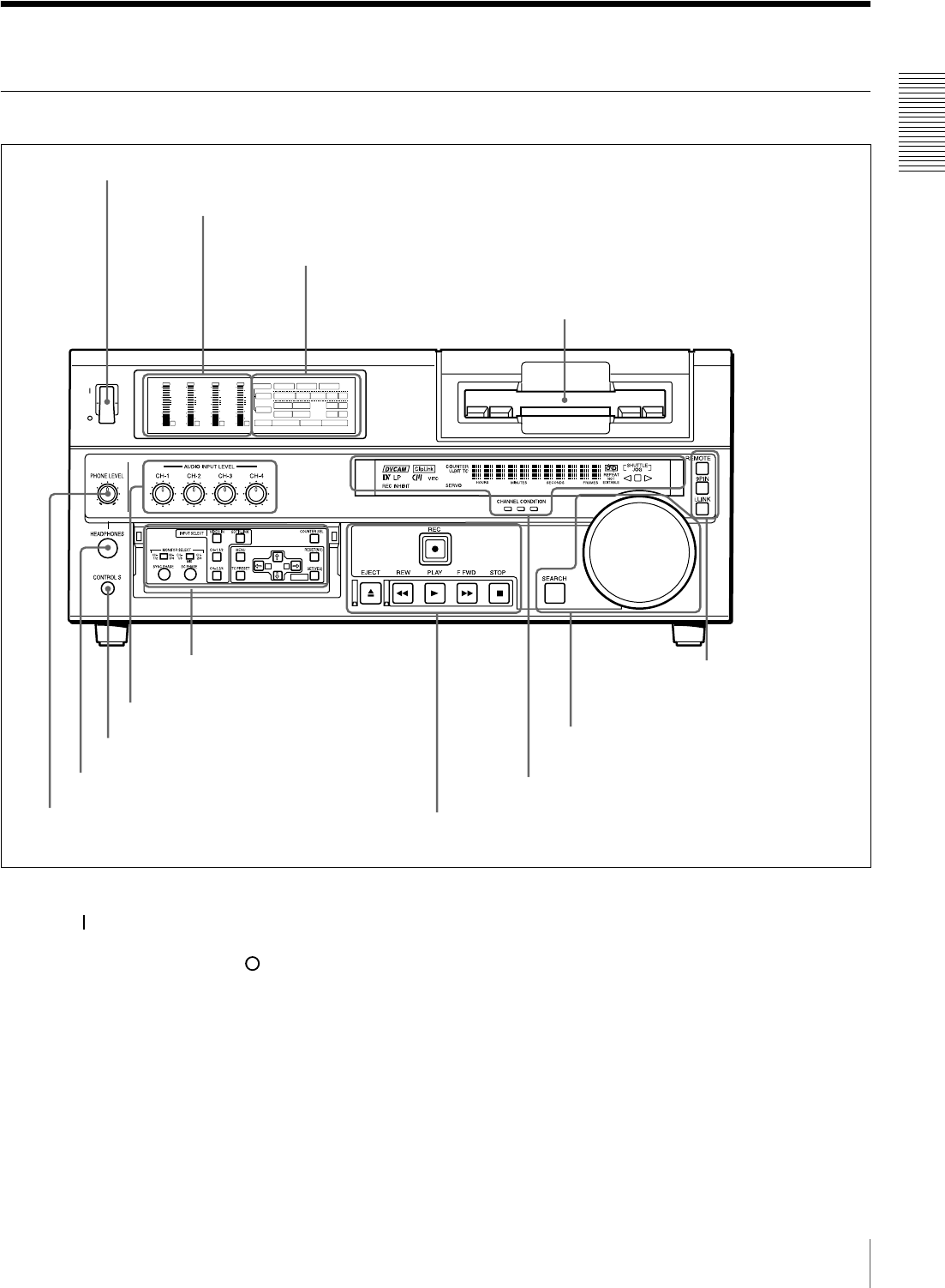
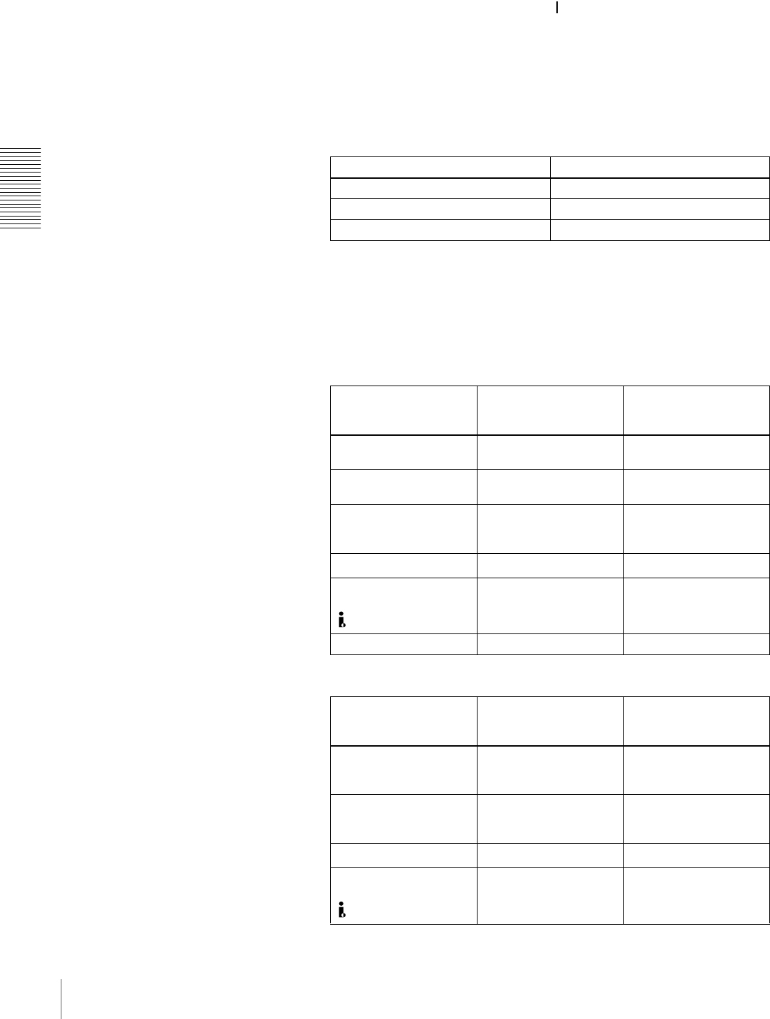
Front Panel
a POWER switch
Press the “ ” side to power the unit on. When the unit is
powered on, the display windows in the front panel lights.
To power the unit off, press the “ ” side of the switch.
bAudio level meters
These show the audio levels of channels 1 to 4 (recording
levels in recording mode or E-E mode* and playback level
in playback mode).
* E-E mode: Abbreviation of “Electric-to-Electric mode.” In this mode,
video and audio signals input to the VCR are output after passing through
internal electric circuits, but not through magnetic conversion circuits such
as heads and tapes. This can be used to check input signals and for
adjusting input signal levels.
cCassette compartment
Accepts DVCAM, DV and DVCPRO (25M)
videocassettes.
For details of usable cassettes, see page 27.
dPHONE LEVEL control knob
Controls the volume of the headphones connected to the
HEADPHONES connector.
INPUT
VIDEO
AUDIO
i.LINK
dB
0
-12
-20
-30
-40
-60
dB
0
1
0
-1
-2
OVER
1
dB
0
-12
-20
-30
-40
-60
dB
0
1
0
-1
-2
OVER
2
dB
0
-12
-20
-30
-40
-60
dB
0
1
0
-1
-2
OVER
3
dB
0
-12
-20
-30
-40
-60
dB
0
1
0
-1
-2
OVER
4
REC MODE
CH11/2
CH23/4
COMPOSITE
2CH4CHPB FS
Y-R,B
48k44.1k32k
S VIDEO
SDI SG
ANALOG
AES/EBU
SDI SG
ANALOG
AES/EBU
SDI SG
POWER
A B
MARK
AInput selection/audio mode
display section (see page 14)
aPOWER switch
cCassette compartment
BMenu control panel (inside of
the door) (see page 15) FRemote control setting
section (see page 20)
ESearch control section
(see page 19)
DDisplay section (see page 18)
gAUDIO INPUT LEVEL control knobs
eHEADPHONES connector
fCONTROL S connector
CTape transport control section (see page 17)
bAudio level meters
dPHONE LEVEL control knob
14 Location and Function of Parts
Chapter 1 Overview
eHEADPHONES connector (stereo phone jack)
Connect stereo headphones for headphone monitoring
during recording or playback.
The audio signal you want to monitor can be selected with
the MONITOR SELECT switches on the menu control
panel.
fCONTROL S connector (stereo minijack)
Connect a SIRCS-compatible remote control unit such as
the DSRM-10.
gAUDIO INPUT LEVEL control knobs
When recording, you can use these knobs to set audio input
levels for CH-1 (channel 1), CH-2, CH-3 and CH-4,
respectively.
You can make these knobs inoperative with the REC
LEVEL menu item (see page 70).
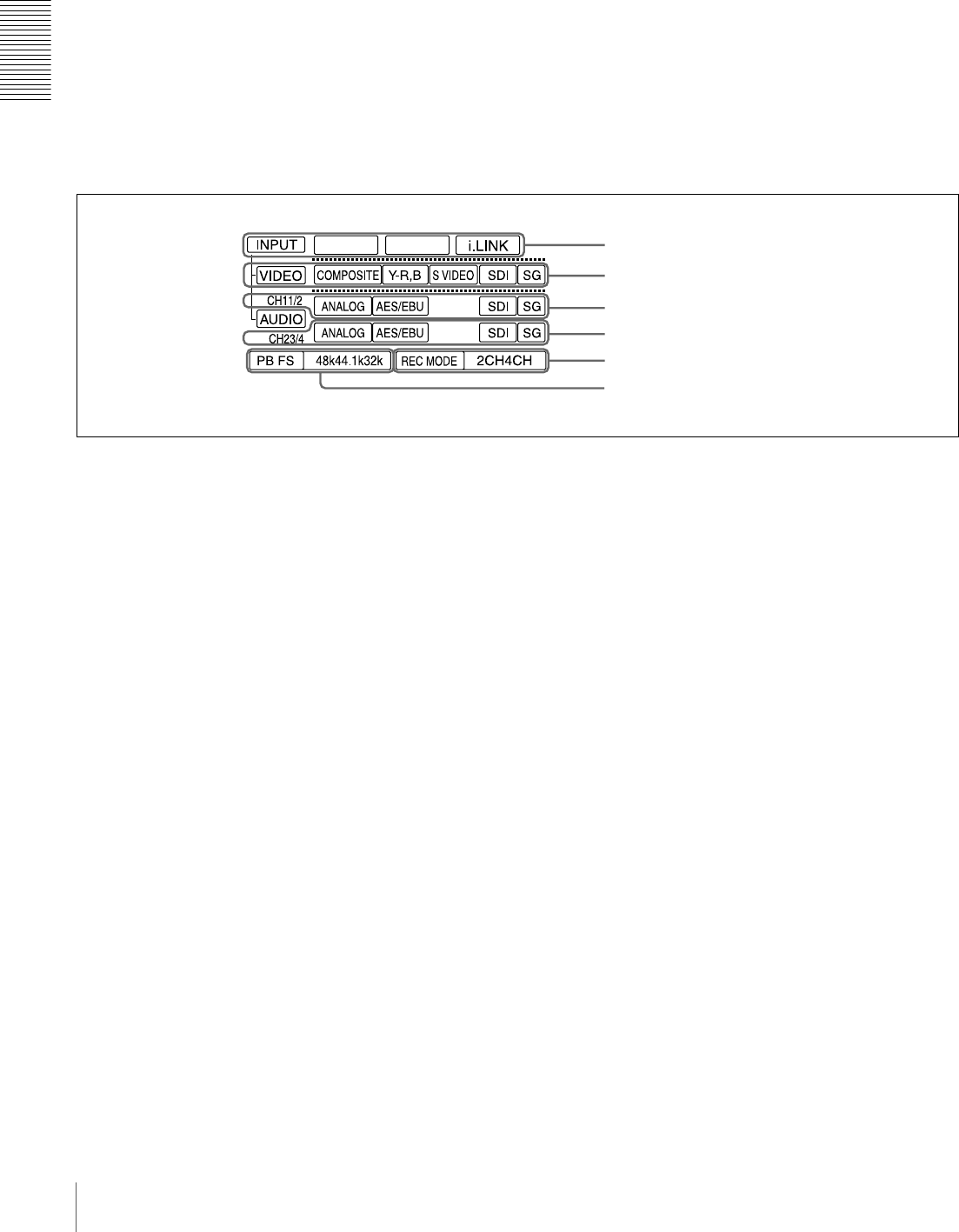
AInput selection/audio mode display section
aINPUT display
i.LINK: When you press the SDTI/i.LINK button in the
INPUT SELECT section, the i.LINK indicator lights.
This indicates that digital video and audio signals in
i.LINK-compatible DV format are currently selected.
bVIDEO display
Indicates the input video signal selected with the VIDEO
IN button in the INPUT SELECT section.
COMPOSITE: Composite video signal
Y−R, B: Y, R−Y and B−Y component video signals
S VIDEO: S-video signal
SDI: SDI video signal (optional DSBK-1801 board
required)
SG: Video test signal
cAUDIO CH1 1/2 display
Indicates the input audio signal selected with the CH-1,1/2
button in the INPUT SELECT section.
ANALOG: Analog audio signal
AES/EBU: Digital audio signal in AES/EBU format
(optional DSBK-1801 board required)
SDI: SDI audio signal (optional DSBK-1801 board
required)
SG: Audio test signal
dAUDIO CH2 3/4 display
Indicates the input audio signal selected with the CH-2,3/4
button in the INPUT SELECT section. The indications
available are the same as for the AUDIO CH1 1/2 display
described above.
eREC MODE (audio recording mode) display
Indicates the audio recording mode (2CH or 4CH) selected
with the REC MODE menu item (see page 69).
fPB FS (playback audio sampling frequency)
display
Indicates the sampling frequency (48 kHz, 44.1 kHz or 32
kHz) at which audio is recorded on tape.
aINPUT display
bVIDEO display
cAUDIO CH1 1/2 display
dAUDIO CH2 3/4 display
eREC MODE display
fPB FS display
15
Location and Function of Parts
Chapter 1 Overview
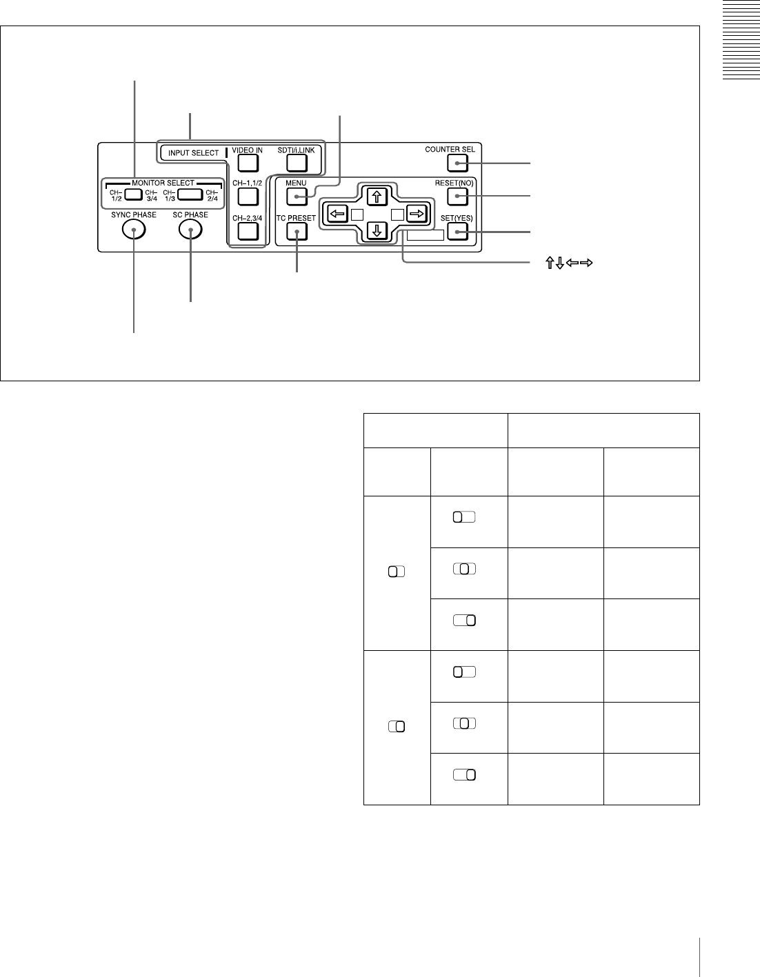
BMenu control panel
The menu control panel is located on the inside of the door
at the lower front of the unit. Pull the top of the door to
open it.
aMONITOR SELECT switches
Use these switches to select the channels for audio output
via the AUDIO MONITOR OUT connector on the rear
panel and the HEADPHONES connector on the front
panel.
Use the left switch to select the basic channel setting, then
use the right switch to select the output format (monaural,
stereo, or mix).
The following table lists the correspondence of left/right
switch settings and channel/output format selections.
MIX
A
B
MARK
cMENU button
bINPUT SELECT section
aMONITOR SELECT switches
dCOUNTER SEL button
fSET (YES) button
eRESET (NO) button
g
hTC PRESET button
iSC PHASE control
jSYNC PHASE control
buttons
Switch setting Selected channel and output
format
Left
switch Right
switch HEADPHONES
connector AUDIO
MONITOR OUT
connector
Channel 1 only
(monaural)
Channel 1 only
(monaural)
Channels 1 and
2 (stereo)
Channels 1 and
2 (mix)
Channel 2 only
(monaural)
Channel 2 only
(monaural)
Channel 3 only
(monaural)
Channel 3 only
(monaural)
Channels 3 and
4 (stereo)
Channels 3 and
4 (mix)
Channel 4 only
(monaural)
Channel 4 only
(monaural)
CH-
1/2
CH-
3/4
CH-
1/3
CH-
2/4
MIX
CH-
1/3
CH-
2/4
MIX
CH-
1/3
CH-
2/4
MIX
CH-
1/2
CH-
3/4
CH-
1/3
CH-
2/4
MIX
CH-
1/3
CH-
2/4
MIX
CH-
1/3
CH-
2/4
MIX

16 Location and Function of Parts
Chapter 1 Overview
bINPUT SELECT section
VIDEO IN button
Each press of this button cycles through the following
input video signal selection options.
• Composite video signal input to the VIDEO IN
connectors
• Component video signals input to the COMPONENT
VIDEO IN connectors
• S-video signal input to the S VIDEO IN connector
• SDI video signal input to the SDI IN connector (optional
DSBK-1801 board required)
• Video test signal (selected with the INT VIDEO SG
menu item (see page 68) generated by the internal signal
generator
In the input selection/audio mode display section, the
VIDEO display shows the selection made with this button.
CH1,1/2 (audio channel 1 or 1/2) button
Each press of this button cycles through the following
input audio signal selection options for audio channel 1
(when in 2-channel mode) or for audio channels 1 and 2
(when in 4-channel mode).
• Analog audio signal(s) input to the AUDIO IN CH-1
connector (when in 2-channel mode) or AUDIO IN CH-
1 and CH-2 connectors (when in 4-channel mode)
• Digital audio signal in AES/EBU format input to the
DIGITAL AUDIO (AES/EBU) IN CH-1/2 connector
(optional DSBK-1801 board required)
• SDI audio signal input to the SDI IN connector (optional
DSBK-1801 board required)
• Audio test signal (selected with the INT AUDIO SG
menu item (see page 71)) generated by the internal
signal generator
In the input selection/audio mode display section, the
AUDIO CH1 1/2 display shows the selection made with
this button.
CH2,3/4 (audio channel 2 or 3/4) button
Each press of this button cycles through the input audio
signal selection options for audio channel 2 (when in 2-
channel mode) or for audio channels 3 and 4 (when in 4-
channel mode). The input audio signal selection options
corresponding to those for the CH1,1/2 button described
above are available.
In the input selection/audio mode display section, the
AUDIO CH2 3/4 display shows the selection made with
this button.
SDTI/i.LINK (SDTI(QSDI) interface/i.LINK selection)
button
Selects digital video and audio signals in i.LINK-
compatible DV format, input to the DV IN/OUT
connector. When you press this button, the i.LINK
indicator lights in the input selection/audio mode display
section.
cMENU button
Press this button to display the menu on the monitor screen
and the time counter display. Press it again to return from
the menu display to the usual display.
On how to use the menu, see Chapter 4 “Menu Settings.”
(see page 59)
dCOUNTER SEL (selection) button
Selects the type of time data to be shown in the time
counter display. Each press of this button cycles through
three indicator display options: COUNTER (CNT: count
value of the time counter), TC (time code), and U-BIT
(user bits).
Note
When the REMOTE button in the remote control setting
section is lit, the COUNTER SEL button does not operate.
In this case, make the time data selection via the remote
equipment that is connected to the REMOTE connector on
the rear panel.
eRESET (NO) button
Press this button to:
• reset menu settings,
• reset the time count (COUNTER) shown in the time
counter display to zero, or
• send a negative response to the prompts issued by the
unit.
fSET (YES) button
Press this button to:
• save new settings, such as selected menu items and time
code settings, to the memory of the unit, or
• send a positive response to the prompts issued by the
unit.
gArrow (JjKk) buttons
Use these buttons to move around the menu items, and also
for setting time code and user bit data.
For details on setting time code and user bit data, see
“Using the Internal Time Code Generator” on page 49.
hTC (time code) PRESET button
Use this button when setting an initial time code value and
user bit data.
For details on setting time code and user bit data, see “To
set the initial time code value and user bit data” on page
49.
iSC (subcarrier) PHASE control
Turn this control to accurately adjust the subcarrier phase
of the composite video output signal of the unit with
respect to the reference video signal. Use a cross-point
(Phillips) screwdriver to turn it.
17
Location and Function of Parts
Chapter 1 Overview
jSYNC (synchronization) PHASE control
Turn this control to accurately adjust the synchronization
phase of the output video signal of the unit with respect to
the reference video signal. Use a cross-point (Phillips)
screwdriver to turn it.
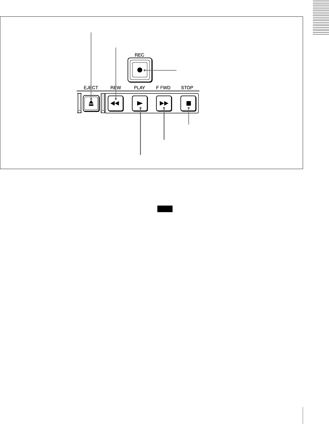
CTape transport control section
aEJECT button
When you press this button, it lights and the cassette is
automatically ejected after a few seconds.
bREW (rewind) button
When you press this button, it lights and the tape starts
rewinding (maximum 85 times normal speed).
When the F. FWD/REW menu item (see page 63) is set to
PB, you can monitor the playback picture during the
rewind.
cREC (record) button
When you press the PLAY button while holding down this
button, it lights and recording begins.
dPLAY button
When you press this button, it lights and playback begins.
If you press this button during recording or editing, the
recording or editing operation is stopped and this unit
enters playback mode.
eF FWD (fast forward) button
When you press this button, it lights and the tape is fast
forwarded (maximum 85 times normal speed).
When the F. FWD/REW menu item (see page 63) is set to
PB, you can monitor the playback picture during the fast
forward.
fSTOP button
Press this button to stop the current tape transport
operation.
Note
No tape transport control buttons other than the EJECT
and STOP buttons will work while the REMOTE button in
the remote control setting section is lit. This can be
changed with the LOCAL ENABLE menu item (see page
63).
aEJECT button
bREW button
cREC button
fSTOP button
eF FWD button
dPLAY button
18 Location and Function of Parts
Chapter 1 Overview
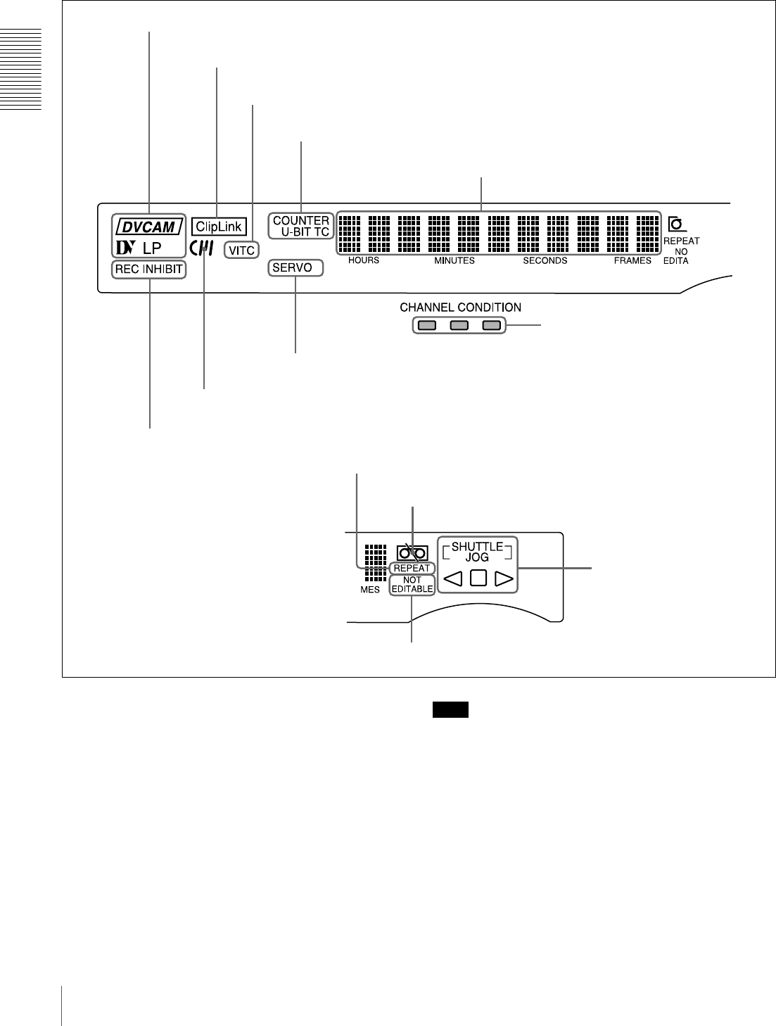
DDisplay section
aRecording/playback format indicators
DVCAM: This lights when a tape recorded in DVCAM
format is played back.
DV: This lights when a tape recorded in consumer DV
format is played back.
LP: This lights when a tape recorded in LP mode is played
back.
When a tape recorded in DVCPRO (25M) format or any
other format than those mentioned above is played back,
none of the above indicators lights.
Note
A tape recorded in LP mode cannot be played back
correctly. When a tape recorded in LP mode is played
back, “DV LP” flashes and audio is muted.
bClipLink indicator
Lights when a cassette is loaded on which ClipLink log
data is stored in the cassette memory.
cVITC indicator
Lights when VITC is being read or recorded regardless of
the data shown in the time counter display.
aRecording/playback format indicators
bClipLink indicator
cVITC indicator
dTime data type indicators
eTime counter display
iCHANNEL CONDITION indicators
jREPEAT indicator
hSERVO indicator
gCassette memory indicator
fREC INHIBIT indicator
kTape end alarm indicator
mNOT EDITABLE indicator
lSHUTTLE/JOG indicators

19
Location and Function of Parts
Chapter 1 Overview
dTime data type indicators
One of the three indicators (COUNTER, U-BIT, and TC)
lights to indicate the type of time data currently shown in
the time counter display.
COUNTER: Count value of the time counter
U-BIT: User bit data
TC: SMPTE time code (for DSR-1800A) or EBU time
code (for DSR-1800AP)
eTime counter display
Indicates the count value of the time counter, time code,
VITC, or user bit data depending on the settings of the
COUNTER SEL button on the menu control panel and the
TC SELECT menu item (see page 66).
Also used to display error messages and setup menu data.
fREC (recording) INHIBIT indicator
Lights in the following cases:
• The REC/SAVE switch on the loaded cassette is in the
SAVE position.
• The REC INHIBIT menu item (see page 63) is set to
ON.
gCassette memory indicator
Lights when a cassette provided with a memory chip
(“cassette memory”) is loaded.
hSERVO indicator
This indicator lights when the drum servo and capstan
servo are locked*.
* Servo lock: This refers to the synchronization of the phase of the drum
rotation and the reference signal for the tape transport position, so that the
video heads can trace the same pattern on the tape for playback and
recording.
iCHANNEL CONDITION indicators
These three-color indicators show the state of the playback
signal.
Green: The state of the playback signal is good.
Yellow: The playback signal is somewhat deteriorated, but
playback is possible.
Red: The playback signal is deteriorated. When the red
indicator remains on, head cleaning or an internal
inspection is necessary.
jREPEAT indicator
This indicator lights when the REPEAT MODE menu item
(see page 62) is set to ON.
kTape end alarm indicator
Starts flashing when the remaining capacity of the tape is
for about 2 minutes.
lSHUTTLE/JOG indicators
When searching in shuttle mode using the search dial, the
SHUTTLE indicator lights, and when searching in jog
mode using the search dial, the JOG indicator lights. When
the search dial is turned clockwise causing playback to
take place in the forward direction, the G indicator lights.
When the search dial is turned counterclockwise causing
playback to take place in the reverse direction, the g
indicator lights. When the tape is stopped, the s indicator
lights.
For more information about the search dial, see “Search
dial” in the next section.
mNOT EDITABLE indicator
Lights during playback of a tape that contains a recording
in other than the DVCAM format. When this indicator is
lit, the recordings contained in the tape can be used as
source material for editing, but editing operations such as
insert editing and assemble editing cannot be performed.
This indicator also lights when the audio recording mode
selected on this unit does not coincide with that of the
loaded tape.
ESearch control section
aSEARCH button
To use the search dial for playback in shuttle or jog mode,
press this button, turning it on. Pressing the dial toggles
between shuttle and jog modes. In shuttle mode, the
SHUTTLE indicator in the display section lights, and in
jog mode, the JOG indicator in the display section lights.
bSearch dial
Turn this to carry out playback in the modes shown in the
following table. Turning the dial clockwise lights the G
indicator in the display section and plays back in the
forward direction. Turning the dial counterclockwise
lights the g indicator in the display section and plays back
in the reverse direction. When the tape is stopped, the s
indicator in the display section lights.
Pressing this dial toggles playback between shuttle mode
and jog mode. When playing back in shuttle mode, the
bSearch dial
aSEARCH button

20 Location and Function of Parts
Chapter 1 Overview
SHUTTLE indicator in the display section lights, and
when playing back in jog mode, the JOG indicator lights.
You can carry out noiseless playback in the range of ±1/2
times normal speed.
Playback modes using the search dial
You can use the SEARCH ENABLE menu item (see page
63) to select either of the following as the operation to be
performed to put the unit into search mode (shuttle or jog).
• Either press the SEARCH button or, except during
recording/editing, turn the search dial (factory default
setting).
• Press the SEARCH button.
FRemote control setting section
Note
When you edit using the DV IN/OUT connector, with
video and audio signal input set to “i.LINK” and remote
control set to “9PIN”, the locations where edit points are
actually set may not be the same as the specified locations.
When you set video and audio signal input to “i.LINK”, set
remote control to “i.LINK” as well.
aREMOTE button
When remote-controlling this unit from the unit connected
to the REMOTE connector (page 25) or DV IN/OUT
connector (page 23), press this button, turning it on.
When reverting to local mode to use the buttons in the tape
transport control section, press this button again, turning it
off.
b9PIN button
When carrying out remote control between this unit and
the unit connected to the REMOTE connector, press this
button, turning it on.
ci.LINK button
When carrying out remote control between this unit and
the unit connected to the DV IN/OUT connector, press
this button, turning it on.
Playback mode Operation and functions
Shuttle Press the SEARCH button or the search
dial so that the SHUTTLE indicator in
the display section lights, then turn the
search dial.
Playback is carried out at a speed
determined by the position of the search
dial. The maximum shuttle mode
playback speed can be changed with the
SHUTTLE menu item (see page 63).
Jog Press the SEARCH button or the search
dial so that the JOG indicator in the
display section lights, then turn the
search dial. Playback is carried out at a
speed determined by the speed of
rotation of the search dial. The playback
speed is up to ±1 times normal speed by
factory default.
The search dial has no detents.
aREMOTE button
b9PIN button
ci.LINK button
21
Location and Function of Parts
Chapter 1 Overview
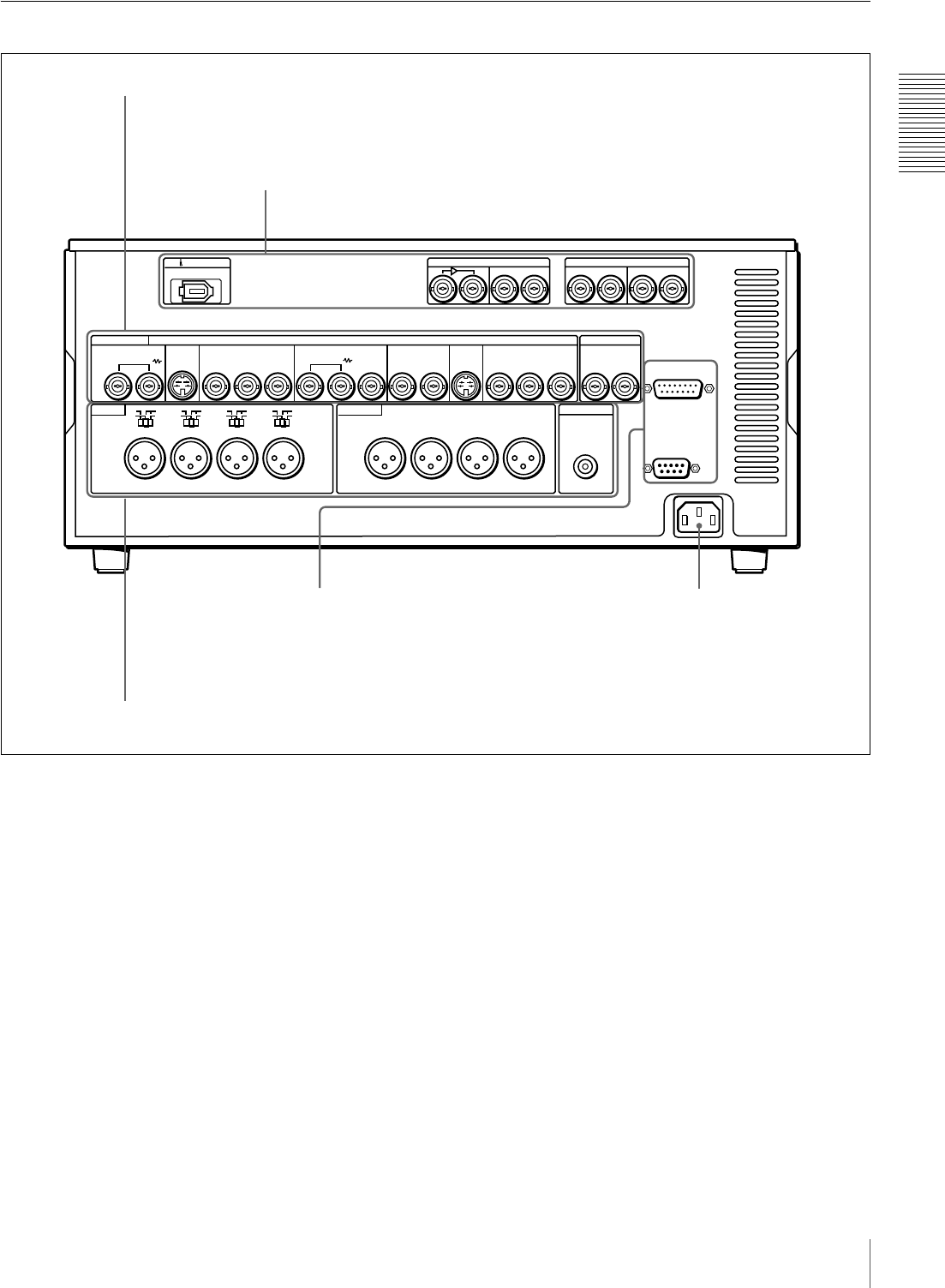
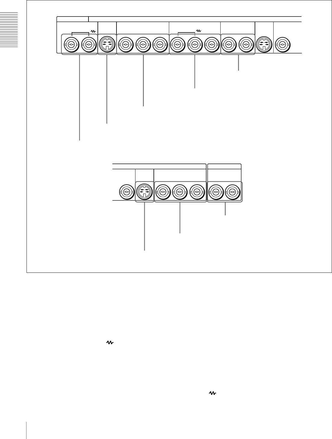
Rear Panel
AC IN connector
Use the supplied power cord to connect this to an AC
outlet.
DIGITAL AUDIO(AES/EBU)
DV IN/OUT
TIME CODE
MONITOR OUT
AUDIO
LEVEL
AUDIO IN AUDIO OUT
IN
REMOTE
VIDEO CONTROL
~AC IN
CH-1
HIGH
LOW
OFF
CH-2 CH-3 CH-4
VIDEO IN VIDEO OUT
CH-1/2
OUT
IN OUT
CH-1/2
CH-3/4 CH-3/4
S VIDEO COMPONENT VIDEO IN COMPONENT VIDEO OUT
REF.VIDEO
YR-Y B-Y
YR-Y B-Y
SDI
ON
600
Ω
LEVEL
HIGH
LOW
OFF
ON
600
Ω
LEVEL
HIGH
LOW
OFF
ON
600
Ω
LEVEL
HIGH
LOW
OFF
ON
600
Ω
CH-1 CH-2 CH-3 CH-4
ANALOG VIDEO
IN
S VIDEO
OUTIN 1 2
(SUPER)
OUT IN OUT
AAnalog video signal input/output section (see page 22)
BDigital signal input/output section (see page 23)
DExternal device connectors (see page 25)
CAnalog audio signal input/output section (see page 24)
AC IN connector
22 Location and Function of Parts
Chapter 1 Overview
AAnalog video signal input/output section
aVIDEO IN connectors (BNC type)
Input an analog composite video signal. This connector
block has a built-in automatic 75 Ω termination switch.
When a signal is input to the left VIDEO IN connector
with no bridging (loop-through) connection made, the
connector is terminated with an impedance of 75 Ω
automatically. To connect the signal input to the left
VIDEO IN connector also to other equipment, use the right
VIDEO IN connector (marked ). When the right
VIDEO IN connector is used, the built-in 75 Ω termination
switch turns off automatically.
bS VIDEO IN connector (4-pin)
Input an S-video signal with separated Y (luminance) and
C (chroma: 3.58 MHz for DSR-1800A or 4.43 MHz for
DSR-1800AP) components to this connector.
cCOMPONENT VIDEO IN Y/R−Y/B−Y connectors
(BNC type)
Input analog component video signals (Y/R−Y/B−Y) to
these connectors.
dREF. (reference) VIDEO IN/OUT connectors
(BNC type)
Input a reference video signal. The IN connector block has
a built-in automatic 75 Ω termination switch. When a
signal is input to the left REF. VIDEO IN connector with
no bridging (loop-through) connection made, the
connector is terminated with an impedance of 75 Ω
automatically. To connect the reference video signal input
to the left REF. VIDEO IN connector also to other
equipment, use the right REF. VIDEO IN connector
(marked ). When the right REF. VIDEO IN connector
VIDEO IN VIDEO OUT
S VIDEO COMPONENT VIDEO IN REF.VIDEO
YY R-Y B-Y
ANALOG VIDEO
IN
S VIDEO
OUTIN 1 2
OUT
(SUPER)
VIDEO OUT
2
TIME CODE
COMPONENT VIDEO OUT
YR-Y B-Y
S VIDEO
OUT IN OUT
eVIDEO OUT 1 and 2 (SUPER)
connectors
dREF. VIDEO IN/OUT connectors
cCOMPONENT VIDEO IN Y/R−Y/B−Y connectors
bS VIDEO IN connector
aVIDEO IN connectors
hTIME CODE IN/OUT connectors
gCOMPONENT VIDEO OUT Y/R−Y/B−Y connectors
fS VIDEO OUT connector
23
Location and Function of Parts
Chapter 1 Overview
is used, the built-in 75 Ω termination switch turns off
automatically.
The REF. VIDEO OUT connector outputs a reference
video signal, except when i.LINK is selected in the INPUT
SELECT section (see page 16).
eVIDEO OUT 1 and 2 (SUPER) connectors (BNC
type)
These connectors output analog composite video signals.
When the CHARA. DISPLAY menu item (see page 65) is
set to ON (factory default setting), connector 2 (SUPER)
outputs a signal with superimposed text information.
fS VIDEO OUT connector (4-pin)
This connector outputs an S-video signal with separated Y
(luminance) and C (chroma: 3.58 MHz for DSR-1800A or
4.43 MHz for DSR-1800AP) components.
gCOMPONENT VIDEO OUT Y/R−Y/B−Y
connectors (BNC type)
These connectors output analog component video signals
(Y/R−Y/B−Y).
hTIME CODE IN/OUT connectors (BNC type)
Input SMPTE time code (for DSR-1800A) or EBU time
code (for DSR-1800AP) externally generated to the IN
connector.
The OUT connector outputs a time code according to the
operating state of the unit, as follows:
During playback: the playback time code
During recording: the time code generated by the internal
time code generator or the time code input to the TIME
CODE IN connector. When the EE OUT PHASE menu
item (see page 67) is set to MUTE, no time code is output.
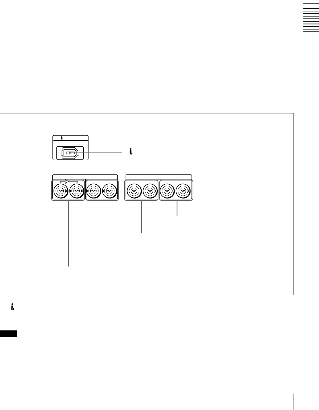
BDigital signal input/output section (optional DSBK-1801 board required)
a DV IN/OUT connector (6-pin IEEE-1394)
This i.LINK-compatible connector inputs and outputs
digital video and audio signals in DV format.
Notes
• When searching at speeds in the range +1/2 to +1/30 or
−1/2 to −1/30 times normal speed, the audio signal output
from this connector and monitored on external
equipment may sound differently from the audio signal
played back on this unit.
• When you connect this unit to another device with a 6-
pin DV connector, always power the other device off and
unplug its power cord from the power output before
connecting or disconnecting the i.LINK cable (DV
cable). If you connect or disconnect the cable with the
power cord still plugged in, power from the DV
connector may flow into this unit, possibly damaging
this unit.
• When you connect this unit to another device with a 6-
pin DV connector, make the connection to the 6-pin DV
DIGITAL AUDIO(AES/EBU)
DV IN/OUT
IN
CH-1/2
OUT
IN OUT
CH-1/2
CH-3/4 CH-3/4
SDI
aDV IN/OUT connector
5DIGITAL AUDIO (AES/EBU) OUT connectors
4DIGITAL AUDIO (AES/EBU) IN connectors
3SDI OUT connectors
2SDI IN and active through output connectors
24 Location and Function of Parts
Chapter 1 Overview
connector on the other device before making the
connection to this unit.
bSDI (Serial Digital Interface) IN (input) and active
through output connectors (BNC type) (optional
DSBK-1801 SDI/AES/EBU Input/Output Board
required)
Input digital video and audio signals in SDI format to the
left-hand connector. The right-hand connector is for an
active-through connection.
cSDI (Serial Digital Interface) OUT connectors
(BNC type) (optional DSBK-1801 SDI/AES/EBU
Input/Output Board required)
Output SDI-format digital video and audio signals. The
same signals are output from both connectors.
dDIGITAL AUDIO (AES/EBU) IN connectors
(BNC type) (optional DSBK-1801 SDI/AES/EBU
Input/Output Board required)
Input digital audio signals in AES/EBU format to these
connectors.
The left-hand connector (CH-1/2) is for audio channels 1
and 2, and the right-hand connector (CH-3/4) is for audio
channels 3 and 4.
eDIGITAL AUDIO (AES/EBU) OUT connectors
(BNC type) (optional DSBK-1801 SDI/AES/EBU
Input/Output Board required)
These connectors output digital audio signals in AES/EBU
format.
The left-hand connector (CH-1/2) is for audio channels 1
and 2, and the right-hand connector (CH-3/4) is for audio
channels 3 and 4.
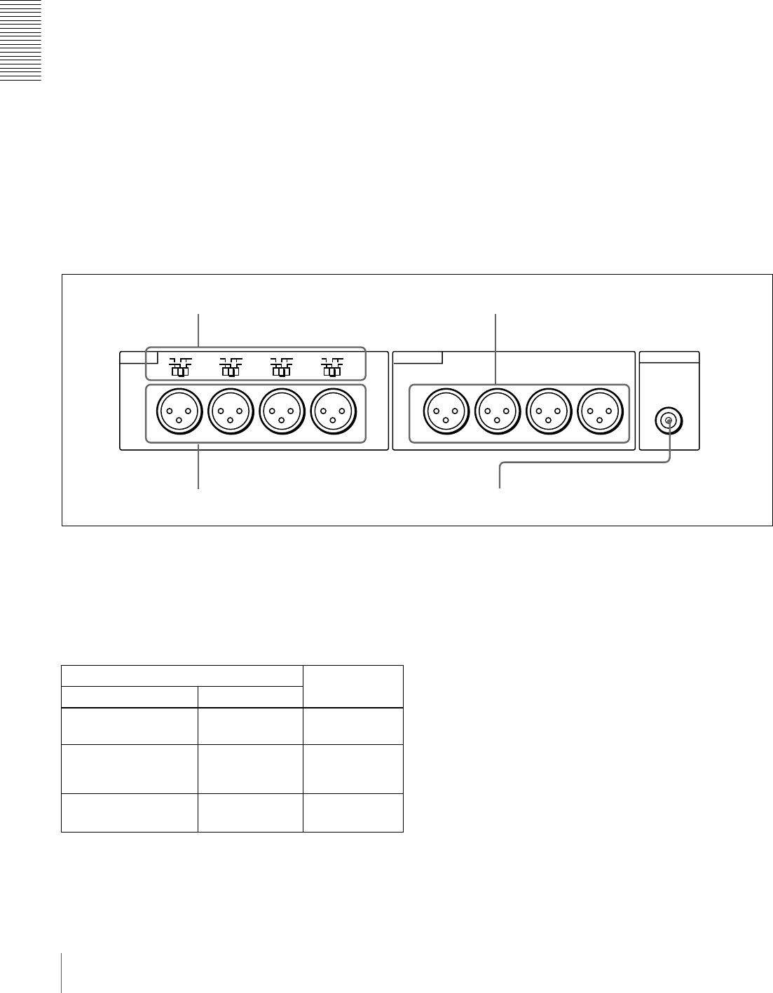
CAnalog audio signal input/output section
aAUDIO IN LEVEL/600 Ω switches
Set these switches for each channel as shown in the
following table, according to the audio input levels to the
AUDIO IN CH-1 to CH-4 connectors and the required
impedance.
a) Selectable on DSR-1800AP only
bAUDIO IN CH-1 (channel 1) to CH-4 connectors
(XLR 3-pin, female)
Use these connectors to connect separate channels of
analog audio input from a player VCR or other external
audio equipment.
You can switch the audio input level setting with the
LEVEL SELECT menu item (see page 71).
cAUDIO OUT CH-1 (channel 1) to CH-4 connectors
(XLR 3-pin, male)
These connectors output channel-1 to channel-4 analog
audio signals, respectively.
It is possible to use the AUDIO OUT CH-3 and AUDIO
OUT CH-4 connectors for audio monitor output for
channels 1 and 2, respectively (use the OUTPUT CH3/4
menu item (see page 71)).
dAUDIO MONITOR OUT connector (RCA phono
jack)
This connector outputs audio signals for monitoring. The
audio signals to be output from this connector can be
MONITOR OUT
AUDIO
LEVEL
AUDIO IN AUDIO OUT
CH-1
HIGH
LOW
OFF
CH-2 CH-3 CH-4
ON
600
Ω
LEVEL
HIGH
LOW
OFF
ON
600
Ω
LEVEL
HIGH
LOW
OFF
ON
600
Ω
LEVEL
HIGH
LOW
OFF
ON
600
Ω
CH-1 CH-2 CH-3 CH-4
dAUDIO MONITOR OUT connector
cAUDIO OUT CH-1 to CH-4 connectors
aAUDIO IN LEVEL/600 Ω switches
bAUDIO IN CH-1 to CH-4 connectors
Settings of the AUDIO IN LEVEL/600 Ω switches
Audio input Switch setting
Level Impedance
−60 dBu
(microphone input)
High impedance
(about 20 kΩ)
LOW-OFF
(left position)
+4/0/−3 a)/−6 dBu
(line audio input)
High impedance
(about 20 kΩ)
HIGH-OFF
(middle
position)
+4/0/−3 a)/−6 dBm
(line audio input)
600 ΩHIGH-ON
(right position)

25
Location and Function of Parts
Chapter 1 Overview
selected with the MONITOR SELECT switches on the
menu control panel.
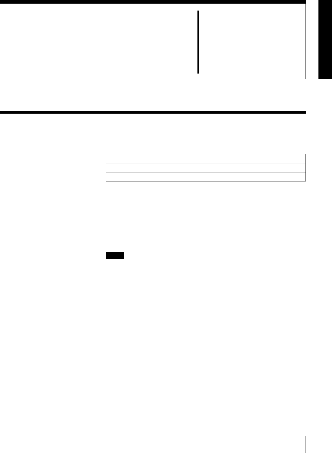
D External device connectors
aVIDEO CONTROL connector (D-sub 15-pin)
For remote control of the internal digital video processor,
connect an optional remote control unit to this connector.
bREMOTE connector (D-sub 9-pin)
Use the optional 9-pin remote cable to connect an editing
controller that supports this unit, or a VCR that supports
editing with two units (DSR-2000A/2000AP, etc.), to
connect those devices to this unit for remote control.
REMOTE
VIDEO CONTROL
aVIDEO CONTROL connector
bREMOTE connector

26 Location and Function of Parts
Chapter 1 Overview
27
Usable Cassettes
Chapter 2
Recording and Playback
Usable Cassettes
This unit can use the DVCAM cassettes listed below.
The * in each model name is actually “ME” (indicating that a cassette memory
is contained), or “N” (indicating that no cassette memory is contained).
The numbers in each model name indicate the maximum recording/playback
time (in minutes) for each model. For example, the PDV-184ME has a
maximum recording/playback time of 184 minutes.
Cassettes usable for playback only
Large- and medium-size DVCPRO (25M) cassettes are usable for playback
only.
Notes
• If you insert an incorrect type of cassette, it will be automatically ejected.
• Although this unit can use DV series consumer cassettes, video or audio noise
may occur on some tapes.
For reliable playback, editing, recording, and storage, use DVCAM cassettes.
• Cassettes that have been recorded by a DV-format recorder can be played
back on this unit but cannot be used for recording at editing operation. When
you insert such a cassette into this unit, the NOT EDITABLE indicator lights
up in the display section on the front panel of this unit.
•See the note in page 18.
Model name Size
PDV-34*/64*/94*/124*/184*Standard size
PDVM-12*/22*/32*/40*Mini size
28 Usable Cassettes
Chapter 2 Recording and Playback
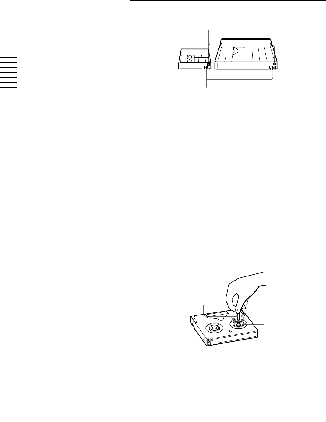
DVCAM cassettes
The following figure illustrates the DVCAM cassettes.
Notes on using cassettes
• Before storing the cassette for a long period of time, rewind the tape to the
beginning and be sure to put the cassette in its storage case, preferably on end
instead of flat on its side.
Storing a cassette in any other condition (not rewound, out of its case, etc.)
may cause the video and audio contents to become damaged over time.
• If the cassette memory connector (contact point) becomes dirty, connection
problems may occur, causing a loss of functions. Remove away any dust or
dirt from this area before using the cassette.
• If the cassette is dropped on the floor or otherwise receives a hard impact, the
tape may become slackened and may not record and/or play back correctly.
For information about how to check the tape for slack, see the next section.
Checking the tape for slack
Using a paper clip or a similar object, turn the reel gently in the direction shown
by the arrow. If the reel does not move, there is no slack. Insert the cassette into
the cassette compartment, and after about 10 seconds take it out.
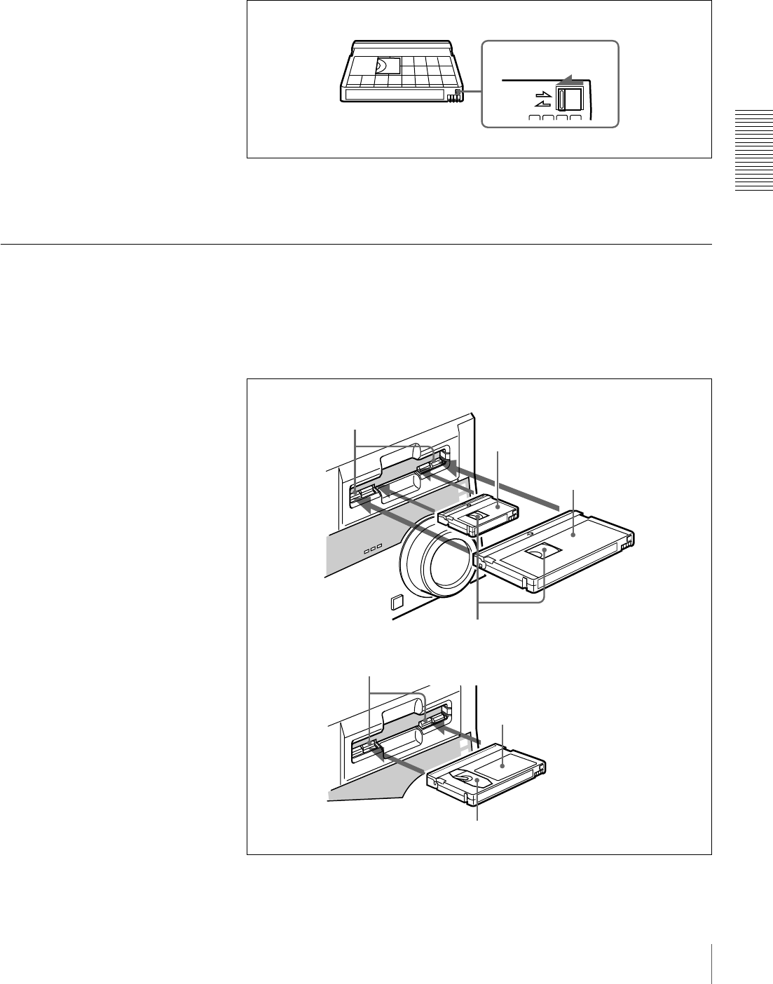
REC/SAVE switch
For details of this switch, see “Preventing accidental
erasure” on page 29
Mini size Standard size
Cassette memory
Paper clip, etc.
Reel
29
Usable Cassettes
Chapter 2 Recording and Playback
Preventing accidental erasure
Set the REC/SAVE switch on the cassette to SAVE to prevent accidental
erasure of recorded contents.
To enable re-recording
Set the REC/SAVE switch to REC.
When this switch is set to SAVE, the unit cannot record on the tape.
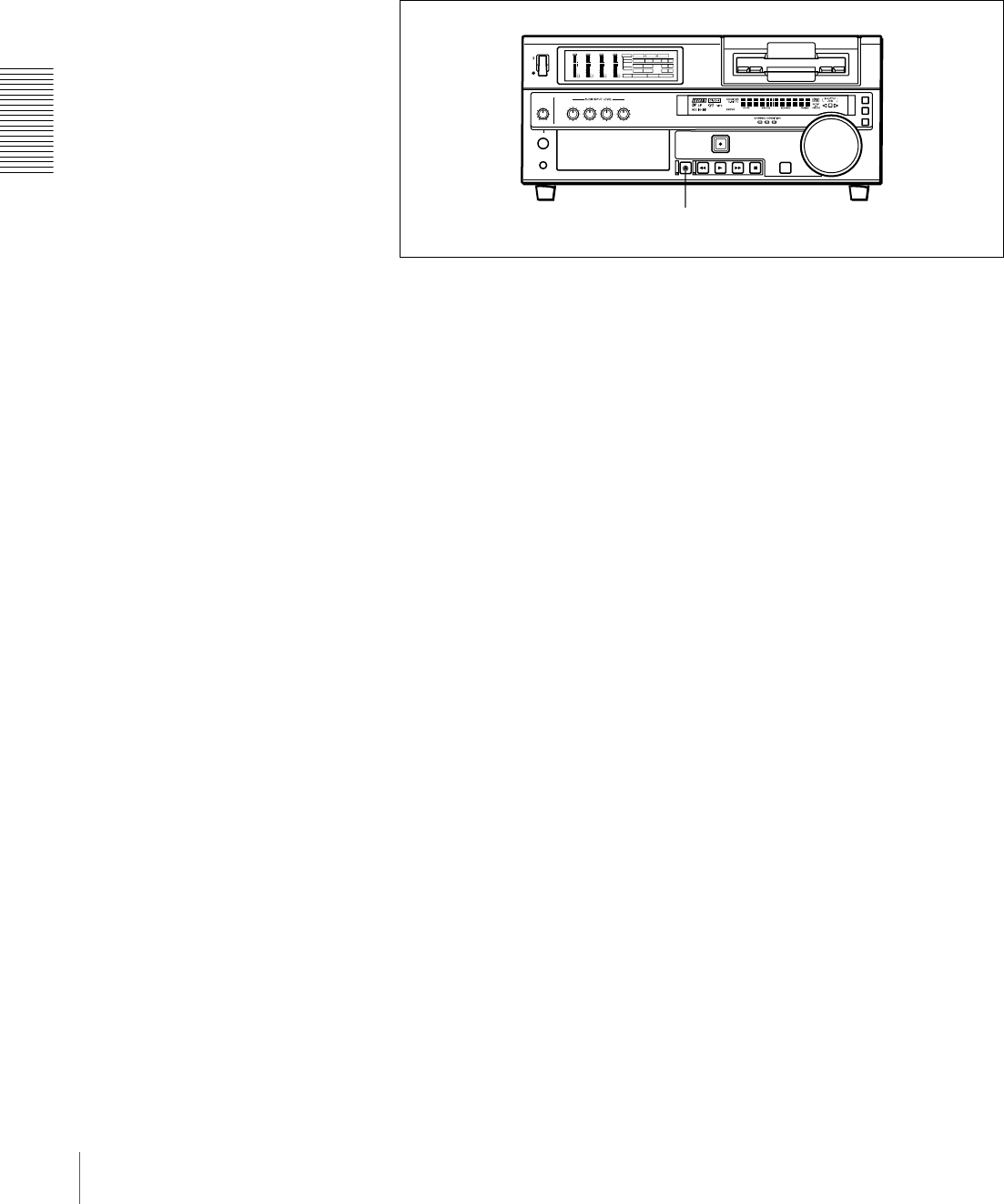
Inserting and Ejecting Cassettes
Inserting a cassette
This unit accepts three sizes of cassette: L (standard size), M (medium size:
DVCPRO) and S (mini size). When inserting a cassette in the unit, make sure
its tape window faces upward as shown in the following figure.
REC
SAVE
REC/SAVE switch
Set to SAVE
Outer guides
Standard size
Tape window facing upward
Inner guides
Tape window facing upward
Mini size (Insert the cassette into the
middle of the cassette compartment.)
Medium size (Align the cassette with
the outer guides, then slide it in over
the inner guides.)
30 Usable Cassettes
Chapter 2 Recording and Playback
No double insertion of cassettes
When you insert a cassette, the orange lock-out plate appears in the cassette
compartment to prevent double insertion.
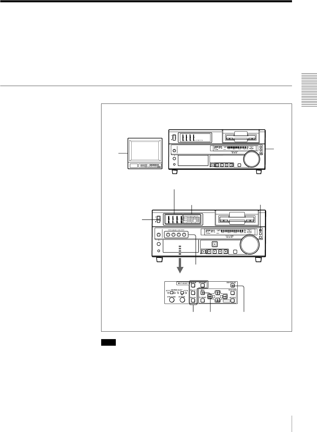
Ejecting a cassette
Press the EJECT button.
INPUT
VIDEO
AUDIO
V:SDTI SDTI i.LINK
dB
0
-12
-20
-30
-40
-60
dB
0
1
0
-1
-2
OVER
1
dB
0
-12
-20
-30
-40
-60
dB
0
1
0
-1
-2
OVER
2
dB
0
-12
-20
-30
-40
-60
dB
0
1
0
-1
-2
OVER
3
dB
0
-12
-20
-30
-40
-60
dB
0
1
0
-1
-2
OVER
4
REC MODE
CH11/2
CH23/4
COMPOSITE
2CH4CH
PB FS
Y-R,B
48k44.1k32k
S VIDEO
SDI SG
ANALOG
AES/EBU
SDI SG
ANALOG
AES/EBU
SDI SG
EJECT button
31
Recording
Chapter 2 Recording and Playback
Recording
This section describes the necessary settings and operations to perform
recording on this unit. The same settings and operations apply whether you are
using the unit as part of an editing system, for dubbing, or as a stand-alone
recorder.
For the necessary connections for recording and the settings not covered in this
section, see Chapter 5 “Connections and Settings” (page 83).
Settings for Recording
Note
When controlling this unit from an editing control unit connected to the
REMOTE connector, see “Remote control setting section” (page 20).
1Power on the video monitor, then set its input switches according to the
signals input from this unit.
2Set up the player to play back a tape.
1
3
7
56 4
2
INPUT
VIDEO
AUDIO
V:SDTI SDTI i.LINK
dB
0
-12
-20
-30
-40
-60
dB
0
1
0
-1
-2
OVER
1
dB
0
-12
-20
-30
-40
-60
dB
0
1
0
-1
-2
OVER
2
dB
0
-12
-20
-30
-40
-60
dB
0
1
0
-1
-2
OVER
3
dB
0
-12
-20
-30
-40
-60
dB
0
1
0
-1
-2
OVER
4
REC MODE
CH11/2
CH23/4
COMPOSITE
2CH4CHPB FS
Y-R,B
48k44.1k32k
S VIDEO
SDI SG
ANALOG
AES/EBU
SDI SG
ANALOG
AES/EBU
SDI SG
A B
MARK
dB
0
-12
-20
-30
-40
-60
dB
0
1
0
-1
-2
OVER
1
dB
0
-12
-20
-30
-40
-60
dB
0
1
0
-1
-2
OVER
2
dB
0
-12
-20
-30
-40
-60
dB
0
1
0
-1
-2
OVER
3
dB
0
-12
-20
-30
-40
-60
dB
0
1
0
-1
-2
OVER
4
PB FS
48k44.1k32k
REMOTE button
Input selection/audio mode
display section
Audio level meters
Video monitor
Player (DSR-1600A/1600AP, etc.)
Recorder (DSR-1800A/1800AP)
32 Recording
Chapter 2 Recording and Playback
For details, refer to the operating instructions for the player.
3Power on this unit by pressing on the side of the POWER switch.
4When the REMOTE button is not lit (the external editing control unit is not
used), use the COUNTER SEL button to select the type of time data to be
used.
Each press of this button cycles through three options: COUNTER (CNT
value), TC (time code), and U-BIT (user bit data). The time data type
indicator for each option lights as it is selected.
When the REMOTE button is lit, selection of the time data type is carried
out at the editing control unit.
5Select the formats of video and audio input signal to be recorded.
Use the buttons in the INPUT SELECT section to select the desired signal
formats. Each selection is shown by a lit indicator in the input selection/
audio mode display section.
a) The indicator does not light even if you press the corresponding button in the INPUT SELECT
section unless the required optional digital input/output board (DSBK-1801) is installed.
Selected time data Time data type indicator
Count value of the time counter COUNTER
Time code TC
User bit data U-BIT
Video input signal
(input connector) Corresponding button
in the INPUT SELECT
section
Lit indicator in the
input selection/audio
mode display section
Composite signal
(VIDEO IN)
VIDEO IN COMPOSITE in VIDEO
group
Separated Y/C signal
(S VIDEO IN)
VIDEO IN S VIDEO in VIDEO
group
Component signal
(COMPONENT VIDEO
IN)
VIDEO IN Y−R, B in VIDEO group
SDI signal (SDI IN) VIDEO IN SDI a) in VIDEO group
i.LINK-compatible digital
video signal in DV format
( DV IN/OUT)
SDTI/i.LINK i.LINK
Internal test video signal VIDEO IN SG in VIDEO group
Audio input signal
(input connector) Corresponding button
in the INPUT SELECT
section
Lit indicator in the
input selection/audio
mode display section
Analog signal
(AUDIO IN CH-1 to CH-
4)
CH-1,1/2 and CH-2,3/4 ANALOG in AUDIO
group
AES/EBU signal
(DIGITAL AUDIO (AES/
EBU) IN)
CH-1,1/2 and CH-2,3/4 AES/EBU a) in AUDIO
group
SDI signal (SDI IN) CH-1,1/2 and CH-2,3/4 SDI a) in AUDIO group
i.LINK-compatible digital
audio signal in DV format
( DV IN/OUT)
SDTI/i.LINK i.LINK

33
Recording
Chapter 2 Recording and Playback
a) The indicator does not light even if you press the corresponding button in the INPUT SELECT
section unless the required optional digital input/output board (DSBK-1801) is installed.
Caution
Once you have started recording, you cannot change the input signal
selection.
6Select the audio mode.
Select either two-channel mode (2CHANNEL) or four-channel mode
(4CHANNEL) with the REC MODE menu item (see page 69). The
corresponding indicator lights in the REC MODE display.
Cautions
• In the DVCAM format, there are two audio recording modes, with either
two channels at 48 kHz or four channels at 32 kHz. It is not possible to
select other modes (for example with four channels at 48 kHz).
• During audio editing, if a signal used in assemble or insert editing is in a
different mode from the base tape, the signals will be discontinuous at the
edit points, and correct editing will not be obtained. For this reason, audio
editing between different modes is inhibited on this unit.
For smooth editing operations, check the audio recording mode of the
base tape beforehand.
• Once you have started recording, you cannot change the audio mode
selection.
• If on a tape there is a point where the audio mode is switched, it is not
possible to carry out insert editing over a section including that point.
7Use the AUDIO INPUT LEVEL control knobs to adjust audio input levels.
Watching the audio level meter, adjust the level so that the meter does not
indicate higher values than 0 dB when the audio signal is at its maximum.
When the level exceeds 0 dB, the OVER indicator lights.
The factory-preset audio recording level is −20 dB (DSR-1800A) or −18 dB
(DSR-1800AP). This setting can be changed using the LEVEL SELECT
menu item (see page 71).
Internal test audio signal CH-1,1/2 and CH-2,3/4 SG in AUDIO group
Audio mode Lit indicator in the REC MODE display
2-channel mode 2CH
4-channel mode 4CH
Audio input signal
(input connector) Corresponding button
in the INPUT SELECT
section
Lit indicator in the
input selection/audio
mode display section

34 Recording
Chapter 2 Recording and Playback
Recording Procedure
This section describes the procedure to perform recording on this unit, showing
an example session in which playback signals coming from a player VCR will
be recorded on the tape loaded in the unit.
Note
When controlling this unit from an editing control unit connected to the
REMOTE connector of this unit, press the REMOTE button to turn it on. When
not, turn off the button.
2
1
3
INPUT
VIDEO
AUDIO
V:SDTI SDTI i.LINK
dB
0
-12
-20
-30
-40
-60
dB
0
1
0
-1
-2
OVER
1
dB
0
-12
-20
-30
-40
-60
dB
0
1
0
-1
-2
OVER
2
dB
0
-12
-20
-30
-40
-60
dB
0
1
0
-1
-2
OVER
3
dB
0
-12
-20
-30
-40
-60
dB
0
1
0
-1
-2
OVER
4
REC MODE
CH11/2
CH23/4
COMPOSITE
2CH4CH
PB FS
Y-R,B
48k44.1k32k
S VIDEO
SDI SG
ANALOG
AES/EBU
SDI SG
ANALOG
AES/EBU
SDI SG
dB
0
-12
-20
-30
-40
-60
dB
0
1
0
-1
-2
OVER
1
dB
0
-12
-20
-30
-40
-60
dB
0
1
0
-1
-2
OVER
2
dB
0
-12
-20
-30
-40
-60
dB
0
1
0
-1
-2
OVER
3
dB
0
-12
-20
-30
-40
-60
dB
0
1
0
-1
-2
OVER
4PB FS
48k44.1k32k
Recorder
(DSR-1800A/1800AP)
Player
(DSR-1600A/1600AP, etc.)
REMOTE button

35
Recording
Chapter 2 Recording and Playback
1After checking the following items, hold the cassette with the tape window
facing upward, then insert it into the recorder (this unit) as illustrated on
page 29.
.
The cassette is automatically drawn into the unit and the tape is wound
round the head drum. The tape is stationary while the head drum rotates, and
the STOP button lights.
If the REC INHIBIT indicator lights:
It indicates that the REC/SAVE switch of the loaded cassette has been set
to SAVE. Press the EJECT button in the tape transport control section to
remove the cassette, then set the REC/SAVE switch to REC and reload the
cassette.
Note
When ejecting and loading cassettes, make sure that the unit has been
powered on.
2Hold down the REC button and press the PLAY button.
This puts the unit into recording mode, and the tape starts moving.
3Press the PLAY button on the player.
The player starts the playback operation, at which point this unit starts
recording the input playback signals.
Cautions
• Once you have started recording, you cannot change the audio mode
selection.
• If on a tape there is a point where the audio mode is switched, it is not
possible to carry out insert editing over a section including that point.
Item to check See section
Make sure that the REC/SAVE switch
of the cassette is set to REC.
“Preventing accidental erasure” on
page 29
Check for tape slack. “Checking the tape for slack” on page
28
Make sure that the “HUMID!” alarm is
not shown in the time counter display.
“Condensation” on page 95
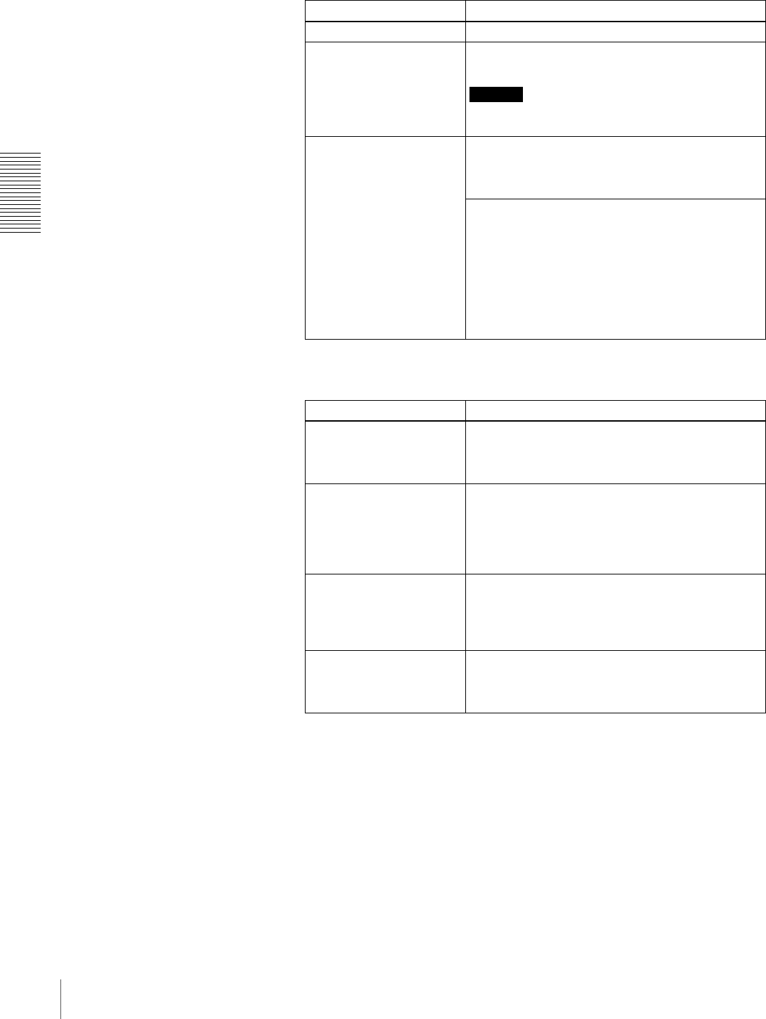
36 Recording
Chapter 2 Recording and Playback
If the following indicators light when a cassette is loaded
To perform the following operations
Indicator It means:
Cassette memory indicator The loaded cassette contains a cassette memory.
ClipLink indicator There is ClipLink log data stored in the cassette
memory on the loaded cassette.
Caution
With such a cassette, carrying out recording destroys
the ClipLink log data.
NOT EDITABLE indicator The recording format of the tape is “DV,” or a
DVCPRO tape is inserted.
Replace the tape with one that has been recorded in
DVCAM format.
The audio recording mode selected on this unit does
not coincide with that of the tape.
• When your current purpose is recording, you can
use the tape as it is.
• When your current purpose is editing, set the unit
for the same audio recording mode as with the
tape.
For more details, see “Troubleshooting” on page
98.
Operation Do this:
Stop recording. Press the STOP button.
The unit enters stop mode, and will automatically
switch to standby off mode after the time period set
with the STOP TIMER menu item (see page 68).
Remove the cassette. Press the EJECT button.
After a few seconds, the tape is unwound from the
head drum and the cassette is automatically ejected.
If a CNT value is shown on the time counter display
(assuming the time data type indicator “COUNTER”
is lit), the CNT value is reset.
Inhibit the unit from
outputting text information
(time data, operation mode
indications, etc.) to the
video monitor.
Set the CHARA. DISPLAY menu item (see page 65)
to OFF.
Change the time period
before the unit switches
from stop mode to standby
off mode.
Change the setting of the STOP TIMER menu item
(see page 68).
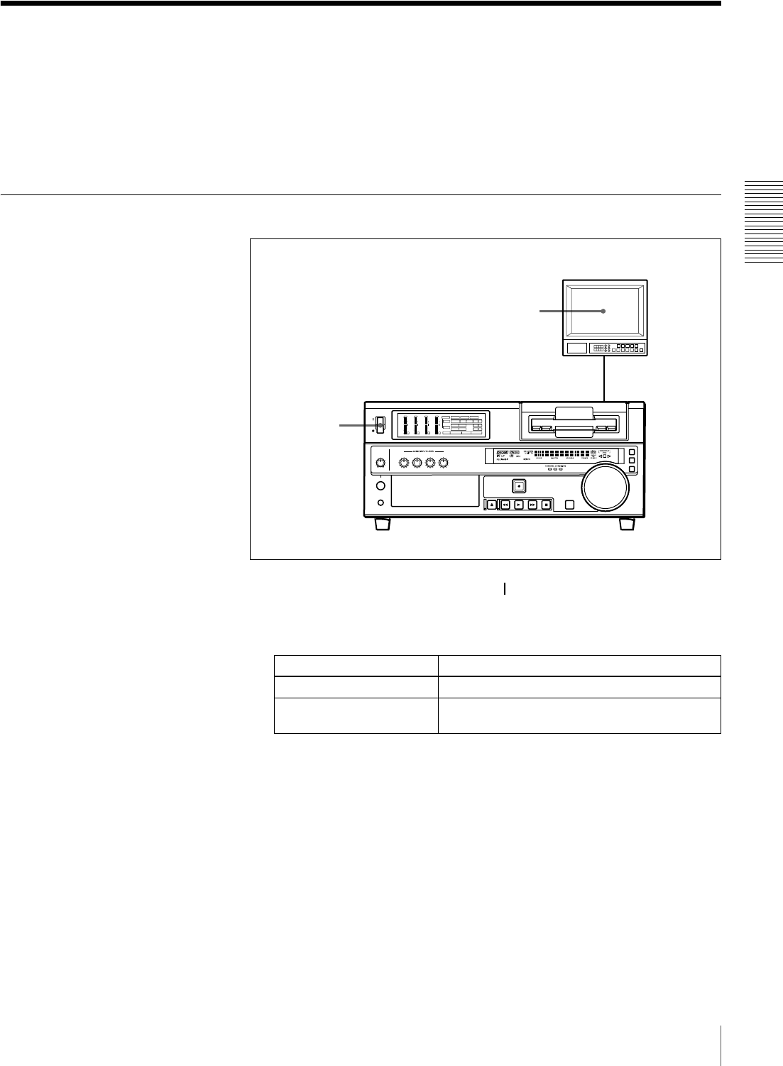
37
Playback
Chapter 2 Recording and Playback
Playback
This section describes the settings and operations necessary to perform playback
on this unit. The same settings and operations apply whether you are using the
unit as part of an editing system, for dubbing, or as a stand-alone player VCR.
For the necessary connections for playback and the settings not covered in this
section, see Chapter 5 “Connections and Settings” (page 83).
Settings for Playback
1Power on this unit by pressing on the side of the POWER switch.
2Power on the video monitor and set its switches as shown below.
Switch Setting
75 Ω termination switch ON (or attach a 75 Ω terminator.)
Input switch Set according to the type of input signal from this
unit.
2
1INPUT
VIDEO
AUDIO
V:SDTI SDTI i.LINK
dB
0
-12
-20
-30
-40
-60
dB
0
1
0
-1
-2
OVER
1
dB
0
-12
-20
-30
-40
-60
dB
0
1
0
-1
-2
OVER
2
dB
0
-12
-20
-30
-40
-60
dB
0
1
0
-1
-2
OVER
3
dB
0
-12
-20
-30
-40
-60
dB
0
1
0
-1
-2
OVER
4
REC MODE
CH11/2
CH23/4
COMPOSITE
2CH4CHPB FS
Y-R , B
48k44.1k32k
S VIDEO
SDI SG
ANALOG
AES/EBU
SDI SG
ANALOG
AES/EBU
SDI SG
Video monitor
Player (DSR-1800A/1800AP)
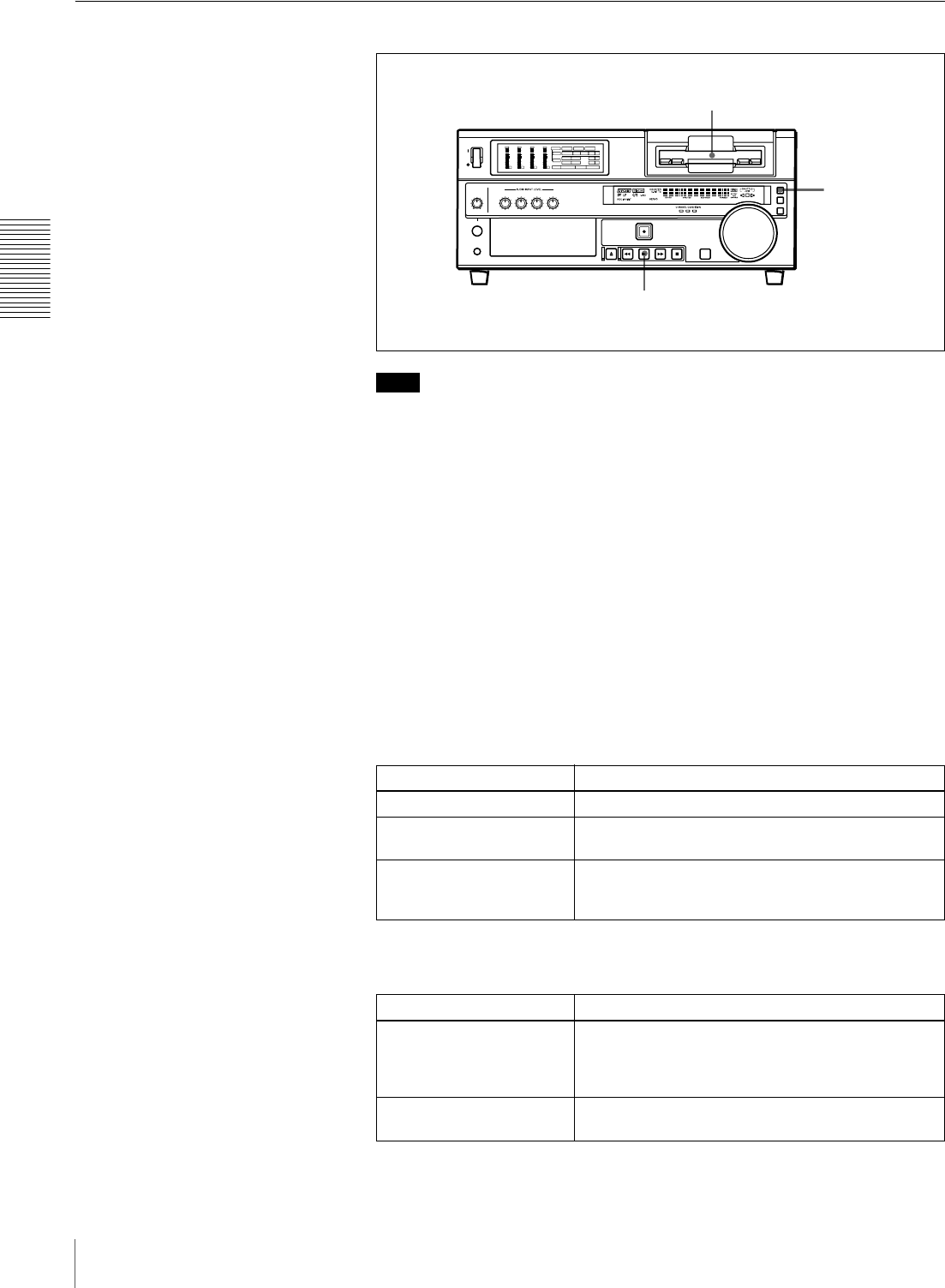
38 Playback
Chapter 2 Recording and Playback
Playback Procedure
Note
When controlling this unit from an editing control unit connected to the
REMOTE connector (see page 25) of this unit, press the REMOTE button
turning it on. When not, turn off the button.
1Insert a cassette.
For details of cassette insertion see page 29, and for usable cassette types
see page 27.
The cassette is automatically drawn into the unit. The STOP button will
light, and a few seconds later a still image will appear on the monitor screen.
2Press the PLAY button.
This starts the playback operation. When the tape is played back all the way
to the end, the unit automatically rewinds it and then stops.
If the following indicators light when a cassette is loaded
To perform the following operations
Indicator It means:
Cassette memory indicator The loaded cassette contains a cassette memory.
ClipLink indicator There is ClipLink log data stored in the cassette
memory on the loaded cassette.
NOT EDITABLE indicator The tape was recorded in the DV format, or a
DVCPRO tape is inserted.
You cannot use it as a recording tape for editing.
Operation Do this:
Stop playback. Press the STOP button.
The unit enters stop mode, and will automatically
switch to standby off mode after the time set with the
STOP TIMER menu item (see page 68).
Adjust the audio playback
level.
Use the audio level control on the monitor.
2
1
INPUT
VIDEO
AUDIO
V:SDTI SDTI i.LINK
dB
0
-12
-20
-30
-40
-60
dB
0
1
0
-1
-2
OVER
1
dB
0
-12
-20
-30
-40
-60
dB
0
1
0
-1
-2
OVER
2
dB
0
-12
-20
-30
-40
-60
dB
0
1
0
-1
-2
OVER
3
dB
0
-12
-20
-30
-40
-60
dB
0
1
0
-1
-2
OVER
4
REC MODE
CH11/2
CH23/4
COMPOSITE
2CH4CHPB FS
Y-R,B
48k44.1k32k
S VIDEO
SDI SG
ANALOG
AES/EBU
SDI SG
ANALOG
AES/EBU
SDI SG
REMOTE button

39
Playback
Chapter 2 Recording and Playback
Play back in shuttle mode
while monitoring the video.
Press the SEARCH button or search dial to light the
SHUTTLE indicator in the display section, then rotate
the search dial.
Playback is carried out at the speed determined by
the angular position of the search dial.
The maximum speed for shuttle playback can be
changed using the SHUTTLE menu item (see page
63).
Play back in jog mode while
monitoring the video.
Press the SEARCH button or search dial to light the
JOG indicator in the display section, then rotate the
search dial.
Playback is carried out at the speed according to the
speed of the search dial rotation. The playback
speed range is ±1 times normal speed by factory
default.
The search dial has no detents.
Inhibit the unit from
outputting text information
(time data, operation mode
indications, etc.) to the
video monitor.
Set the CHARA. DISPLAY menu item (see page 65)
to OFF.
Remove the cassette. Press the EJECT button.
If a CNT value is shown on the time counter display,
the CNT value is reset.
Disable the automatic
rewind function.
Set the AUTO REW menu item (see page 64) to
DISABLE.
Change the time period
before the unit switches
from stop mode to standby
off mode.
Change the setting of the STOP TIMER menu item
(see page 68).
Operation Do this:
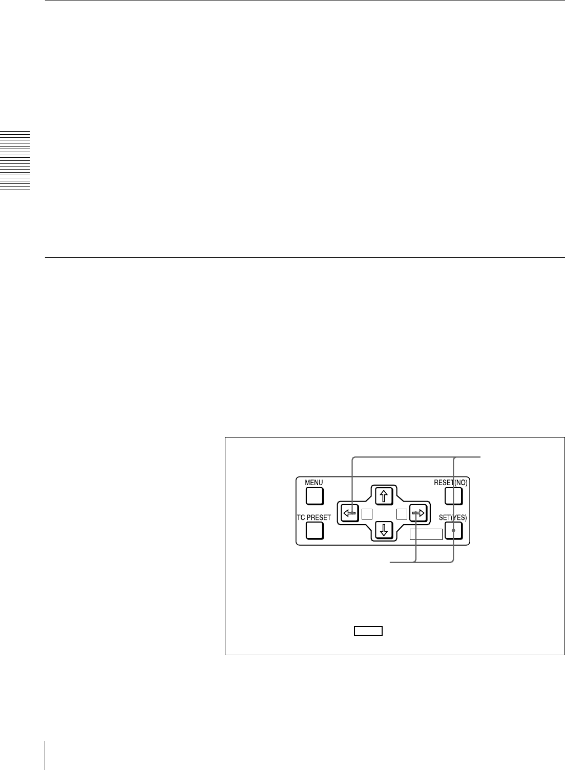
40 Playback
Chapter 2 Recording and Playback
Repeat Playback—Automatic Cyclical Playback
Proceed as follows to perform automatic cyclical playback of recording (repeat
playback) between selected start and end points.
1Set the desired repeat start and end points with the REPEAT FUNCTION
menu item (see page 62).
You can set points A and B as start and end points by following the
procedure described in the next section.
2Set the REPEAT MODE menu item (see page 62) to ON.
The REPEAT indicator lights.
3Press the SET (YES) button to save the new setting and close the menu.
4Press the PLAY button.
The unit repeats playback between the repeat start and end points set in step
1.
Setting Points A and B for Repeat Playback
You can set the repeat playback start point (point A) and end point (point B) by
using the current tape position or inputting time code values.
To perform repeat playback after setting points A and B, press the PLAY button
when the REMOTE button is off. When the DSRM-10 Remote Control Unit is
connected to the CONTROL S connector on the front panel, you can also start
repeat playback by pressing its PLAY button with the REMOTE button of this
unit off.
Setting the current tape position as point A or B
Proceed as follows to set the current tape position as point A or B for repeat
playback.
A B
MARK
Buttons used for setting the
current tape position as
point B
Buttons used for
setting the current
tape position as
point A
In the following explanation of how to set points A and B for repeat
playback, these three buttons are referred to as the KA button, Bk
button, and SET (YES) button, respectively.
MARK
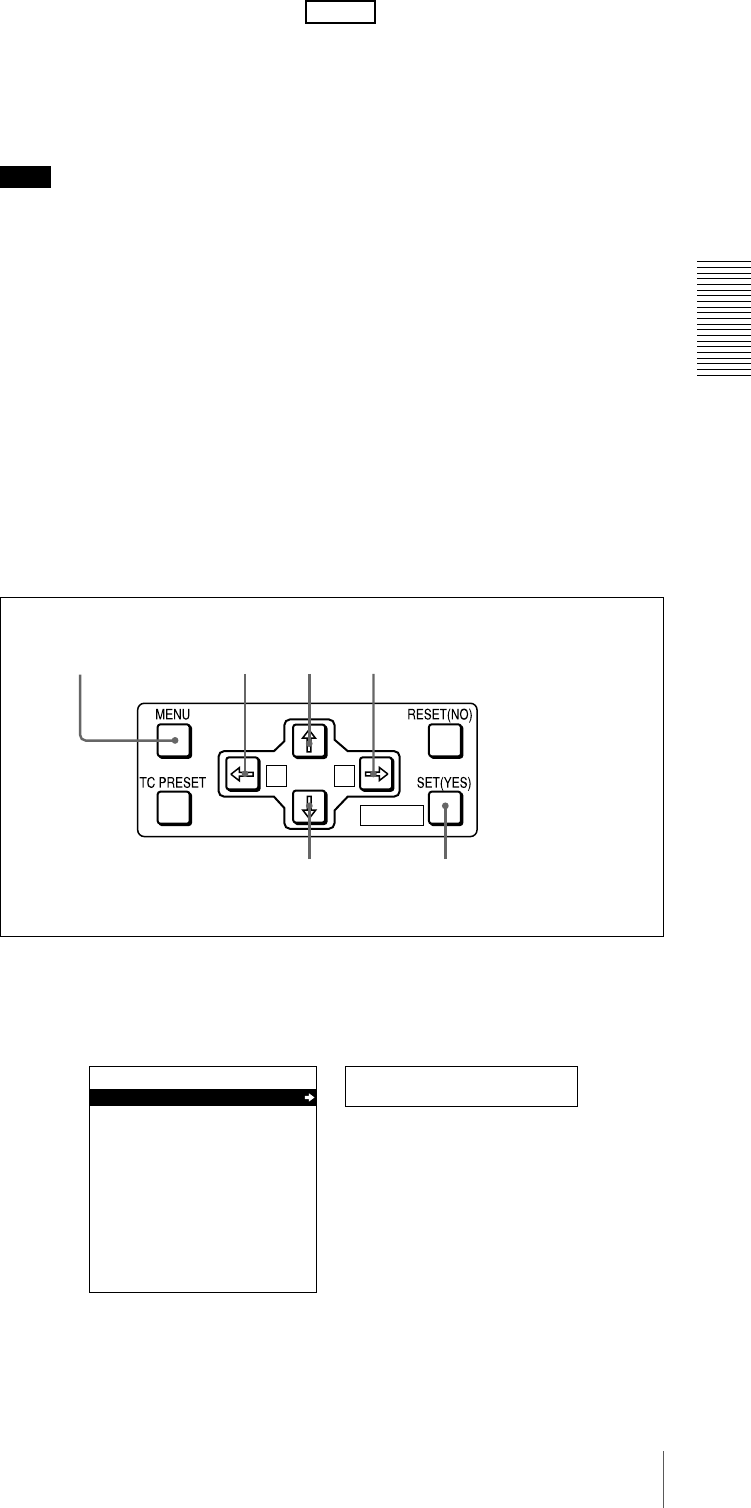
41
Playback
Chapter 2 Recording and Playback
While holding down the SET (YES) button on the menu control panel,
press the KA or Bk button. The time code value of the current tape
position is set as point A or B, and a message “A set” or “B set” is displayed for
0.5 second in the time counter display.
Once set, the point A or B time code value is held in the non-volatile memory
of the unit until changed. It is not lost when the unit is powered off.
Note
When setting point A or B, you can only use a time code value. Even when
COUNTER is selected with the COUNTER SEL button, you cannot use a CNT
value to set point A or B.
To check the point A or B time code value
Press the KA or Bk button on the menu control panel. While the button is
held down, the point A or B time code value is displayed on the monitor and in
the time counter display.
If you hold down the KA and Bk buttons simultaneously, the value shown
is the point B time code value minus the point A time code value. If the point A
time code value is greater than the point B time code value, a minus sign (−) is
shown before the value.
Inputting time code values for points A and B
Using the following procedure, you can modify the time code value for point A
or B.
1Press the MENU button.
The following menu display appears.
MARK
A B
MARK
1,15
5,7,9,12 13
8,11 12 2,3,4,6,10,11
Setup menu
SYSTEM MENU
SETUP MENU
AUTO FUNCTION
HOURS METER
Monitor screen
Time counter display

42 Playback
Chapter 2 Recording and Playback
2With “SETUP MENU” selected, press the Bk button.
The display changes as follows.
3With “OPERATIONAL FUNCTION” selected, press the Bk button.
The display changes as follows.
4With “REPEAT FUNCTION” selected, press the Bk button.
The contents of the REPEAT FUNCTION menu item are displayed.
Operational
SETUP MENU
OPERATIONAL FUNCTION
DISPLAY CONTROL
TIME CODE
SETUP BANK OPERATION
MENU GRADE :BASIC
Time counter display
Monitor screen
>REP FUNC
SETUP MENU
OPERATIONAL FUNCTION
REPEAT FUNCTION
AUTO EE SELECT
LOCAL ENABLE :STP&EJ
Monitor screen
Time counter display
>> REPEAT MD
SETUP MENU
:OFF
:
T.TOP
:
V.END
OPERATIONAL FUNCTION
REPEAT FUNCTION
REPEAT MODE
REPEAT TOP
REPEAT END
A PRESET
B PRESET
Monitor screen
Time counter display
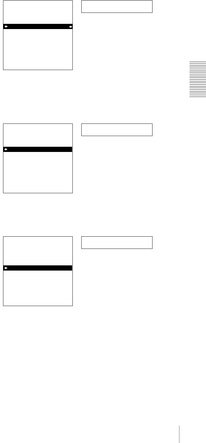
43
Playback
Chapter 2 Recording and Playback
5Press the j button to select “REPEAT TOP.”
6Press the Bk button.
The display changes as follows.
7Press the j button to select “A POINT.”
>> REP TOP
SETUP MENU
OPERATIONAL FUNCTION
REPEAT FUNCTION
REPEAT MODE
REPEAT TOP
REPEAT END
A PRESET
B PRESET
:OFF
:
T.TOP
:
V.END
Monitor screen
Time counter display
>>> Tape top
SETUP MENU
OPERATIONAL FUNCTION
REPEAT FUNCTION
REPEAT TOP
* TAPE TOP
A POINT
:
T.TOP
:
V.END
Monitor screen
Time counter display
>>> A point
SETUP MENU
:
T.TOP
:
V.END
OPERATIONAL FUNCTION
REPEAT FUNCTION
REPEAT TOP
* TAPE TOP
A POINT
Monitor screen
Time counter display
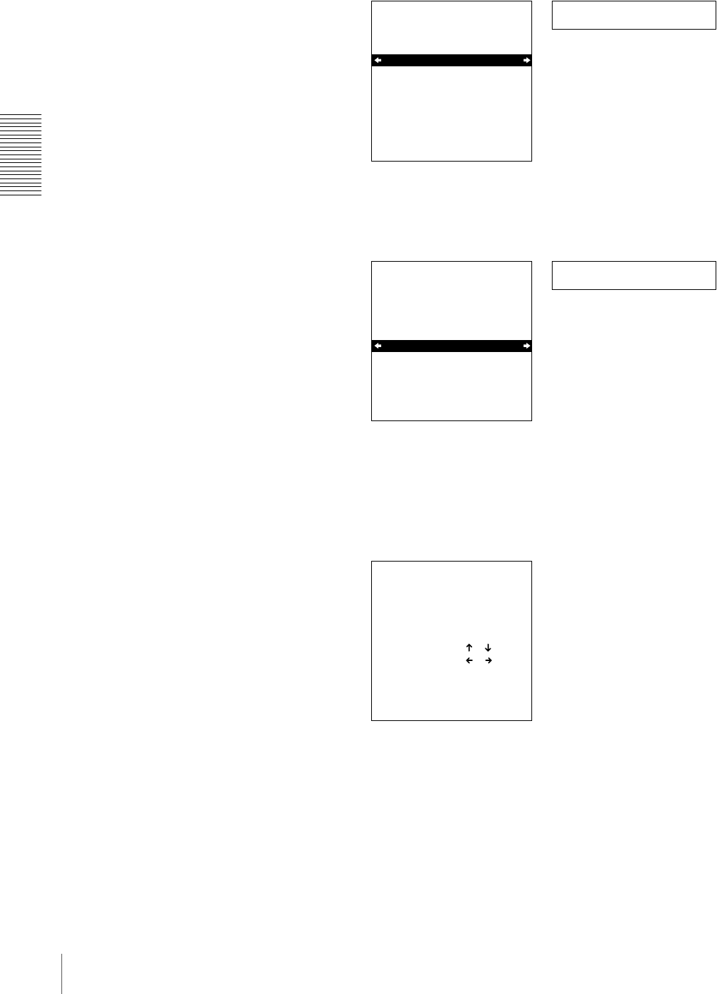
44 Playback
Chapter 2 Recording and Playback
8Press the KA button.
The display changes as follows.
9Press the j button to select “A PRESET.”
10Press the Bk button.
The A PRESET MODE screen appears. The time code value of the current
point A is displayed below the screen title.
11Use the KA or Bk button to select the digit in the time code value
display that you want to change.
Each press of the button causes the digit to the left or right to begin flashing.
Holding the button down moves the flashing digit continuously.
If you want to clear the time code value, press the RESET (NO) button. The
value is cleared to 00:00:00:00, and the leftmost digit begins flashing.
>> REP TOP
SETUP MENU
OPERATIONAL FUNCTION
REPEAT FUNCTION
REPEAT MODE
REPEAT TOP
REPEAT END
A PRESET
B PRESET
:OFF
.
A
:
V.END
Monitor screen
Time counter display
>> A preset
SETUP MENU
OPERATIONAL FUNCTION
REPEAT FUNCTION
REPEAT MODE
REPEAT TOP
REPEAT END
A PRESET
B PRESET
:OFF
.
A
:
V.END
Monitor screen
Time counter display
A PRESET MODE
A 00:00:00:00
INC/DEC : ( )( )KEY
SHIFT : ( )( )KEY
CLEAR : RESET KEY
DATA SAVE : SET KEY
TO MENU : MENU KEY
Monitor screen

45
Playback
Chapter 2 Recording and Playback
12Press the J or j button to increment or decrement the value of the flashing
digit.
Each press of the button increments or decrements the value. Holding the
button down increments or decrements the value continuously. To change
other digits, return to step 11.
13Press the SET (YES) button to confirm the defined value.
The message “NOW SAVING...” is displayed on the monitor screen and
“Saving...” is shown in the time counter display while the new setting is
being saved in memory.
Caution
The new setting may be lost if you power off the unit during the saving
operation. Wait until the saving operation is completed before powering the
unit off.
If you want to discard the changed value
Press the MENU button instead of pressing the SET (YES) button
to return to the menu display, then press the MENU button again to end the
menu operation without saving the changed value into memory.
After the saving operation is completed, the monitor screen and time
counter display return to the REPEAT FUNCTION setting display as
shown in step 9.
14To set point B, refer to steps 5 to 13. (Select “REPEAT END” in step 5, “B
POINT” in step 7, and “B PRESET” in step 9.)
15Press the MENU button to close the menu.
Cuing Up to Any Desired Position Set as Point A or B
You can set any desired tape position as point A or B and cue up to the set point
when required. To cue up to point A or B, holding down the KA or Bk
button on the menu control panel, press the REW button in the tape transport
control section.
For the methods of setting points A and B, see “Setting Points A and B for
Repeat Playback” (page 40).
MARK
MARK

46 Playback
Chapter 2 Recording and Playback

47
Setting the Time Data
Chapter 3
Convenient Functions
for Editing Operation
Setting the Time Data
This unit is provided with the following functions related
to time data.
• Display and reset CNT value
• Set, display, record, and play back SMPTE/EBU time
code and user bit data
• Set, display, record, and play back VITC
The unit can output the time code read from the tape as an
analog (LTC) signal while in normal-speed playback
mode, and receive an external analog time code (LTC)
signal.
Note
The unit outputs no signal from the TIME CODE OUT
connector unless it is in normal-speed playback mode.
The following explains how to use these functions.
Displaying Time Data and Operation
Mode Indications
Time data and operation mode indications can be
displayed on the monitor screen.
Time data can also be displayed in the time counter display
on this unit.
To view time data and operation mode
indications on the monitor screen
Set the CHARA. DISPLAY menu item (see page 65) to
ON (factory default setting).
The time data and the indication of the current operation
mode are superimposed on the video signal that is being
output from the VIDEO OUT 2 (SUPER) connector, and
can be viewed on the monitor screen.
Use the DISPLAY CONTROL menu items (see page 65)
to select the information displayed and the character type
and position of the indications.
When you set the SUB STATUS menu item (see page 65)
to other than OFF, you can also display supplementary
status information on the monitor screen such as editing
mode settings and the operating mode of the internal time
code generator.
For details of supplementary status information, see
“Displaying Supplementary Status Information” on page
80.
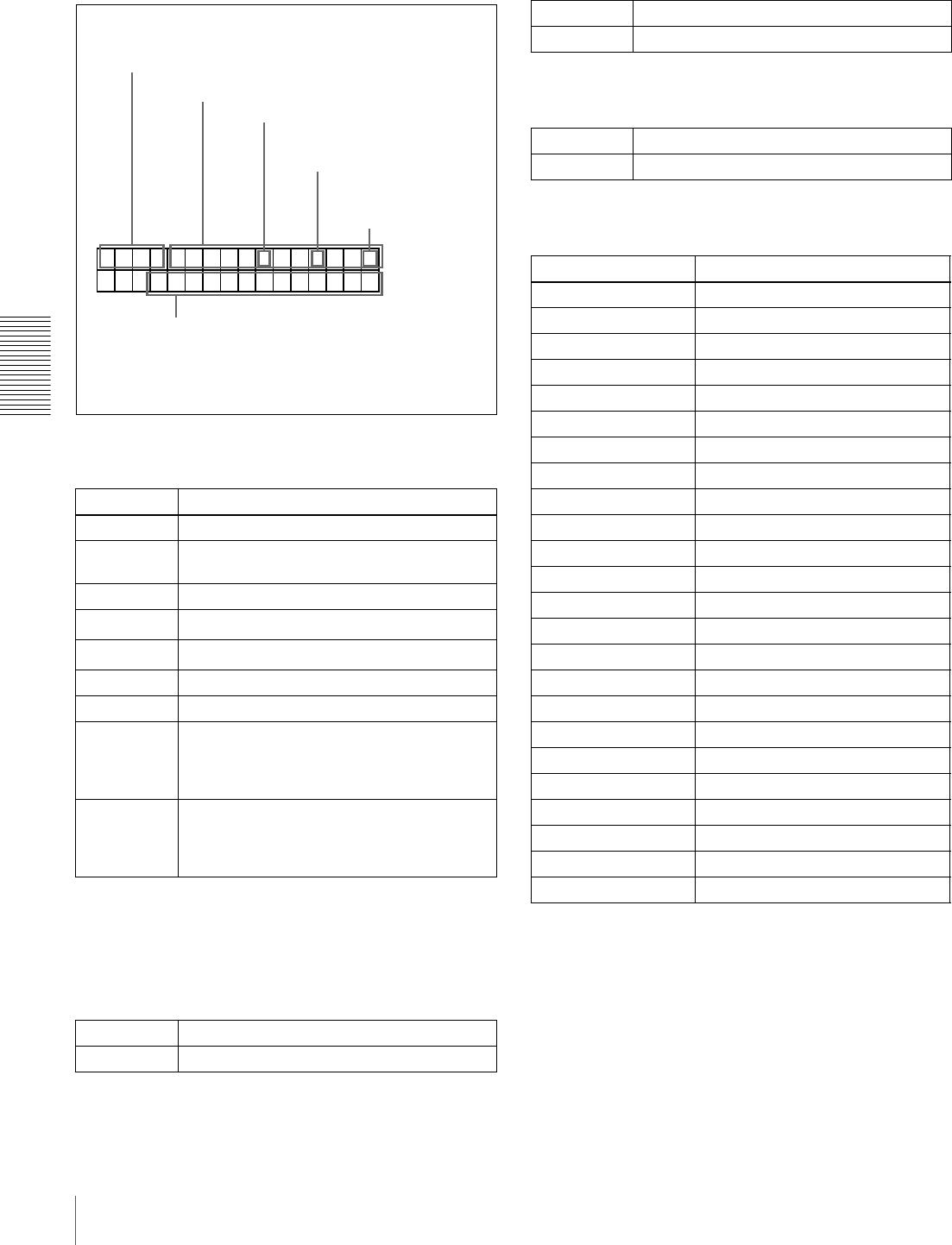
48 Setting the Time Data
Chapter 3 Convenient Functions for Editing Operation
Monitor screen contents
The contents of the monitor screen are shown below.
ATime data type
The following time data type indications are displayed.
a) You can switch between TC and VITC using the TC SELECT menu item
(see page 66).
b) “*” is displayed when data cannot be read in correctly.
B Drop frame indication for time code reader (on
DSR-1800A only)
C Drop frame indication for time code generator
(for DSR-1800A only)
D VITC field indication
E DSR-1800A/1800AP operation mode
Indication Description
CNT Count value of the time counter
TCR Time code data from time code reader
(factory default setting)
UBR User bit data from time code reader
TCR. Time code data from VITC reader a)
UBR. User bit data from VITC reader a)
TCG Time code data from time code generator
UBG User bit data from time code generator
T*R b) Time code data from time code reader. The
asterisk indicates an interpolation by the time
code reader to make up for the time code
data not correctly read from the tape.
U*R b) User bit data from the time code reader. The
asterisk indicates that last data is retained by
the time code reader, as the new data has
not been read correctly from the tape.
. Drop frame mode (factory default setting)
: Non-drop frame mode
TCR
PLAY
00:04 47
.07*
LOCK
.
BDrop frame indication
for time code reader a)
CDrop frame indication
for time code
generator a)
a) This character (.) can appear on the DSR-1800A only. The
character to appear in these two columns is always a colon
( : ) on the DSR-1800AP.
Time data
ATime data type
EDSR-1800A/1800AP operation mode
DVITC field
indication
. Drop frame mode (factory default setting)
: Non-drop frame mode
(blank) Display fields 1 and 3.
*Display fields 2 and 4.
Display Operation mode
CASSETTE OUT Cassette is not loaded.
THREADING Tape loading
UNTHREADING Tape unloading
STANDBY OFF Standby off mode
T. RELEASE Tape tension released
STOP Stop mode
F. FWD Fast forward mode
REW Rewind mode
PREROLL Preroll mode
PLAY Playback mode (servo unlocked)
PLAY LOCK Playback mode (servo locked)
PLAY-PAUSE Temporary stop of playback
REC Record mode (servo unlocked)
REC LOCK Record mode (servo locked)
REC-PAUSE Temporary stop of recording
EDIT Edit mode (servo unlocked)
EDIT LOCK Edit mode (servo locked)
JOG STILL Still picture in jog mode
JOG FWD Jog mode in forward direction
JOG REV Jog mode in reverse direction
SHUTTLE (Speed) Shuttle mode
AUTO EDIT Automatic editing mode
PREVIEW Preview mode
REVIEW Review mode
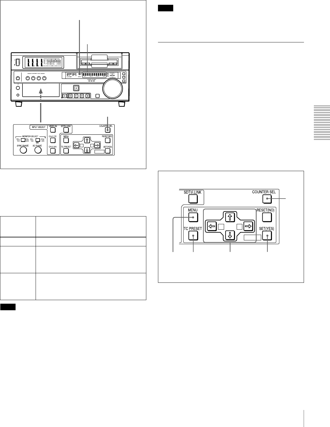
49
Setting the Time Data
Chapter 3 Convenient Functions for Editing Operation
To display the desired time data in the time
counter display
Open the door on the lower part of the front panel, and
press the COUNTER SEL button.
Each press of this button cycles through three options:
CNT value, time code, and user bit data. The time data type
indicator for each option lights as it is selected.
Note
When the REMOTE button on the front panel is lit, the
COUNTER SEL button does not operate while the tape is
moving. In such cases, use the external equipment
connected to the REMOTE connector on the rear panel to
select the time data.
To reset the CNT value
Press the RESET (NO) button on the menu control panel.
This resets the CNT value to 0:00:00:00.
Note
During playback, if the recording on the tape includes
discontinuities, the counter may operate incorrectly at the
corresponding points.
Using the Internal Time Code
Generator
You can set the initial time code value before recording the
time code generated by the internal time code generator
onto a tape. In addition, you can use the user bits to record
such data as the date, time, scene number, reel number, or
other useful information.
When an external time code generator is connected to the
TIME CODE IN connector, the internal time code
generator can be locked to (synchronized with) an external
time code.
To set the initial time code value and user
bit data
1Press the COUNTER SEL button to light the time data
type indicator “TC” or “U-BIT.”
TC: To set the initial time code value.
U-BIT: To set user bit data
The current time code value or user bit data is shown
in the time counter display.
Time data
type
indicator
Time data shown in the time counter
display
COUNTER CNT (count value of the time counter)
TC Time code (when recording, the time code is
generated by the internal time code
generator; when playing back, the time code
is read from the tape.)
U-BIT User bit data (when recording, the user bit
data is according to the most recent settings;
when playing back, the user bit data is read
from the tape.)
A B
MARK
INPUT
VIDEO
AUDIO
V:SDTI SDTI i.LINK
dB
0
-12
-20
-30
-40
-60
dB
0
1
0
-1
-2
OVER
1
dB
0
-12
-20
-30
-40
-60
dB
0
1
0
-1
-2
OVER
2
dB
0
-12
-20
-30
-40
-60
dB
0
1
0
-1
-2
OVER
3
dB
0
-12
-20
-30
-40
-60
dB
0
1
0
-1
-2
OVER
4
REC MODE
CH11/2
CH23/4
COMPOSITE
2CH4CH
PB FS
Y-R , B
48k44.1k32k
S VIDEO
SDI SG
ANALOG
AES/EBU
SDI SG
ANALOG
AES/EBU
SDI SG
COUNTER SEL button
Time data type indicators
Time counter display
A B
MARK
2 3 4,5,6 7
1
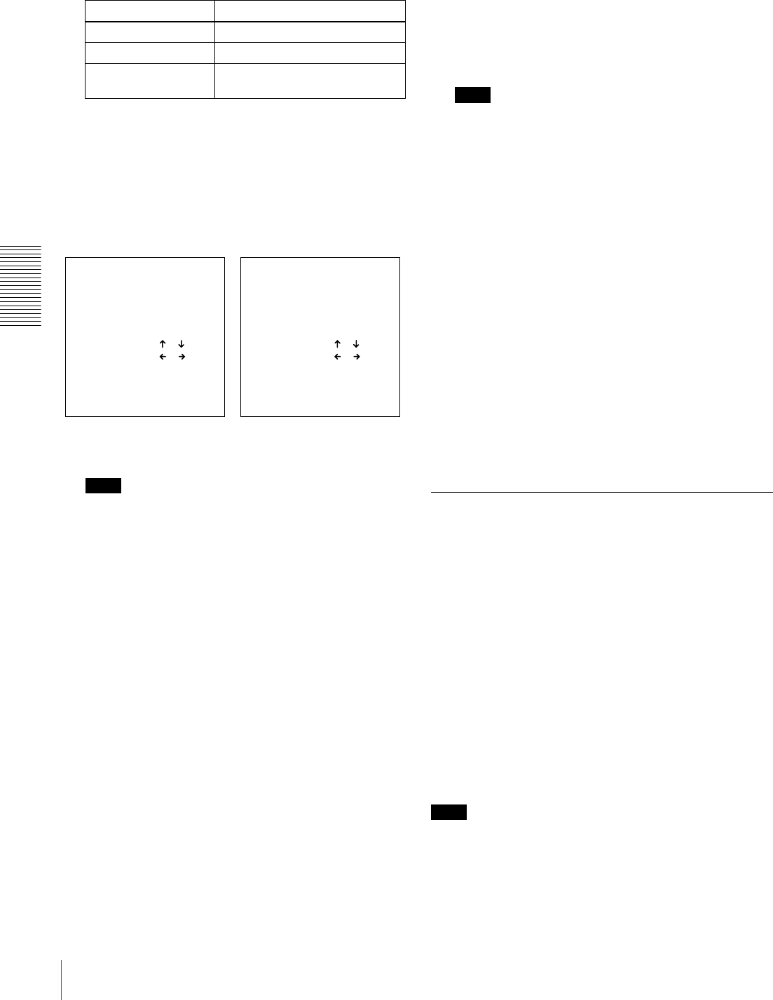
50 Setting the Time Data
Chapter 3 Convenient Functions for Editing Operation
2Set the TIME CODE menu items (see page 66) as
shown below.
3Press the TC PRESET button on the menu control
panel.
The current setting is shown on the monitor screen and
in the time counter display on the front panel. The
leftmost digit keeps flashing.
One of the following menu screens is displayed on the
monitor depending on the setting made in step 1.
Note
If you press the TC PRESET button while CNT value
is being displayed, the message “COUNTER MODE
IS SELECTED.” will appear on the monitor screen
and “CNT mode!” will appear in the time counter
display on the front panel. If this happens, press the
COUNTER SEL button to light the time data type
indicator “TC” or “U-BIT.”
4Use the K and k buttons to move the flashing digit
to the value to be changed.
5Use the J and j buttons to change the value of the
flashing digit.
Enter hexadecimal values (0 to 9, A to F) when setting
user bit data.
6Repeat steps 4 and 5 until you have set the desired
values for all digits.
To set a value of 00:00:00:00, simply press the RESET
(NO) button.
7Press the SET (YES) button.
The message “NOW SAVING...” appears on the
monitor screen, “Saving...” appears in the time counter
display, and the new settings are stored in memory.
After this saving operation is completed, the monitor
screen and the time counter display return to their
usual status.
Note
The set data may be lost if you power off the unit while
the above saving operation is in progress. Wait until
the saving operation is completed before powering off.
Advancement of internal time code
generator
The internal time code generator can advance in either of
two modes, which can be set with the RUN MODE menu
item (see page 66).
FREE RUN: Advancement starts when the data saving
operation is completed.
REC RUN: Advancement starts when recording starts and
stops when recording stops.
To set the current time as the initial time
code value
In step 2 above, set the RUN MODE menu item (see page
66) to FREE RUN, then set the current time (format:
HH:MM:SS:FF = hours: minutes:seconds:frame number)
in step 3 and subsequent steps.
Synchronizing Internal and External
Time Codes
The internal time code generator can be synchronized with
an external time code (LTC) input to this unit.
To synchronize the internal time code to
external time code
Input an external time code (LTC) signal to the TIME
CODE IN connector, then set the TC MODE menu item
(see page 66) to EXT REGEN.
The internal time code generator locks onto the external
time code and starts advancing. Once the internal time
code generator has been synchronized in this way, you can
disconnect the external time code input and this unit will
maintain the synchronized time code.
Note
When the selected input mode is “i.LINK” (the i.LINK
indicator is lit in the INPUT display), setting the TC
MODE menu item (see page 66) to EXT REGEN causes
the internal time code generator to automatically
Menu item Setting
TC MODE “INT PRESET”
RUN MODE “FREE RUN” or “REC RUN”
DF MODE
(for DSR-1800A only)
Normally “ON (DF)”
TC PRESET MODE
TCG 00:00:00:00
INC/DEC : ( )( )KEY
SHIFT : ( )( )KEY
CLEAR : RESET KEY
DATA SAVE : SET KEY
ABORT : TC PRESET KEY
UB PRESET MODE
UBG 00:00:00:00
INC/DEC : ( )( )KEY
SHIFT : ( )( )KEY
CLEAR : RESET KEY
DATA SAVE : SET KEY
ABORT : TC PRESET KEY
Initial time code value setting
screen
User bit setting screen
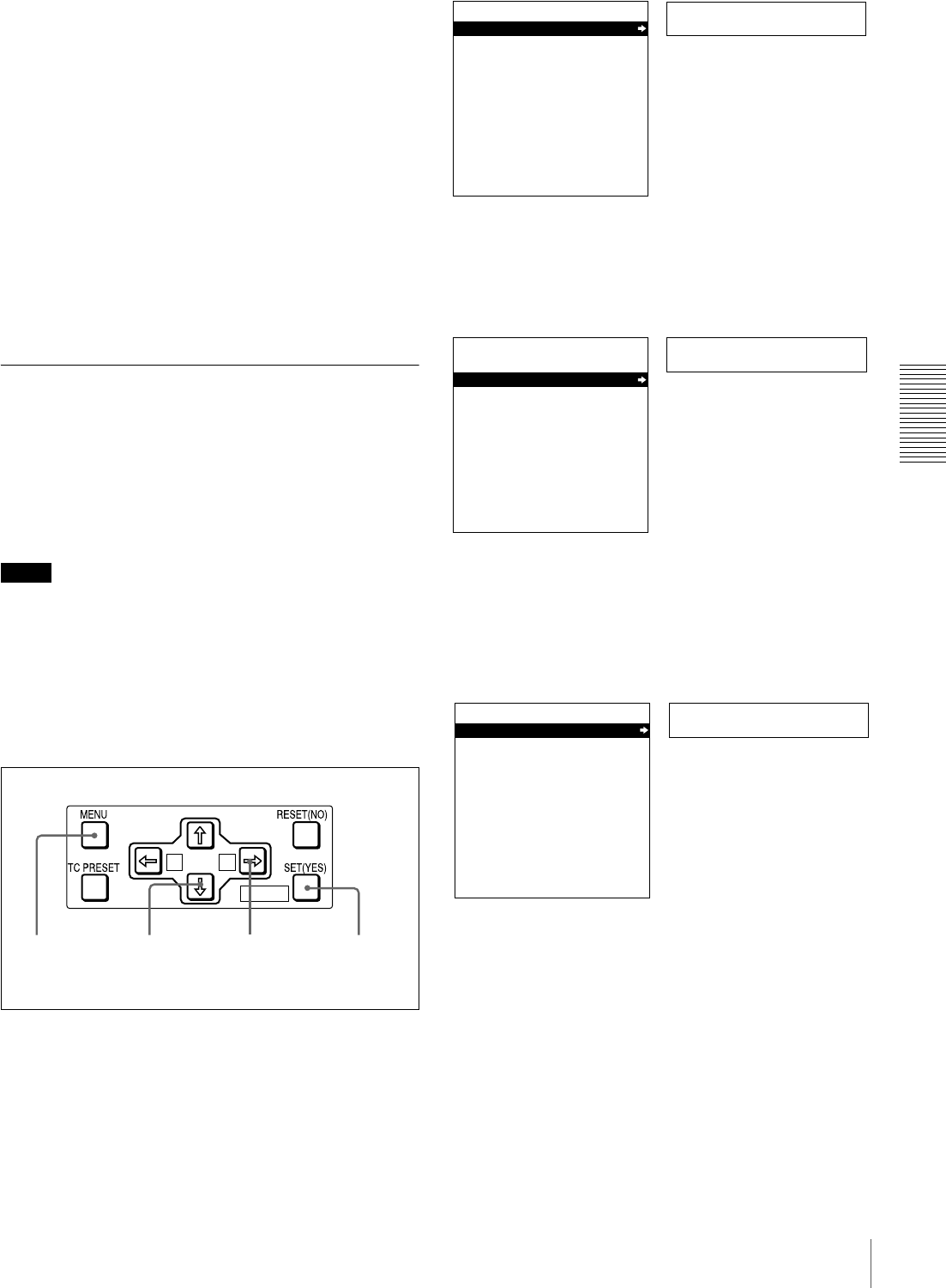
51
Setting the Time Data
Chapter 3 Convenient Functions for Editing Operation
synchronize with the external time code input to the unit
via the i.LINK interface.
Once an external time code signal has been input, the
internal time code advancement mode and frame count
mode are automatically set as follows:
Advancement mode: FREE RUN
Frame count mode: Same as external time code (drop
frame or non-drop frame)
To confirm external synchronization
Press the STOP button to put the unit into stop mode, then
press the REC button.
Look at the time counter display and check that the time
code value displayed there matches the external time code
value.
Rerecording the Time Code—TC
Insert Function
The TC insert function makes it possible to use the internal
time code generator to rewrite time code or user bits when
the time code recorded on a tape is discontinuous.
You can start recording time code from an initial value
which can be set freely (see page 49).
Notes
• Use a tape which is recorded in the DVCAM format.
(You cannot use the TC insert function with a tape
recorded in DV format.)
• The time code recording starts from the current tape
position. Cue the tape up beforehand to the required start
position.
• If you use a tape on which ClipLink log data is recorded,
the ClipLink log data will be lost.
1Open the door on the lower part of the front panel, then
press the MENU button.
2Press the J or j button to select “AUTO
FUNCTION.”
3Press the k button.
This displays the items in the level 1 of the auto mode
execution menu.
4Press the j button to select “TC INSERT.”
A B
MARK
1 2,4 7,83,5
Setup menu
SYSTEM MENU
SETUP MENU
AUTO FUNCTION
HOURS METER
Monitor screen
Time counter display
Auto func
SYSTEM MENU
SETUP MENU
AUTO FUNCTION
HOURS METER
Monitor screen
Time counter display
i.LINK DUB
AUTO FUNCTION MENU
i.LINK DUBBING
TC INSERT
Monitor screen
Time counter display

52 Setting the Time Data
Chapter 3 Convenient Functions for Editing Operation
5Press the k button.
The following message appears.
6Insert the cassette.
A message to confirm the TC insert operation appears.
To cancel the TC insert operation
Press the MENU button.
7Press the SET (YES) button.
Time code recording starts from the current tape
position.
When the recording ends, the message “TC INSERT
COMPLETED. PUSH THE YES BUTTON.” appears
on the monitor screen and “Completed” appears in the
time counter display.
8Press the SET (YES) button to exit the menu.
TC insert
AUTO FUNCTION MENU
i.LINK DUBBING
TC INSERT
Monitor screen
Time counter display
Set tape!
TC INSERT
INSERT THE TAPE IN
THIS VTR.
ABORT:MENU KEY
Monitor screen
Time counter display
TC insert?
TC INSERT
START TC INSERT?
START:YES KEY
ABORT:MENU KEY
Monitor screen
Time counter display
Executing
TC INSERT
EXECUTING.
TCR 00:00:00:00
UBR 00:00:00:00
ABORT:MENU KEY
Monitor screen
Time counter display
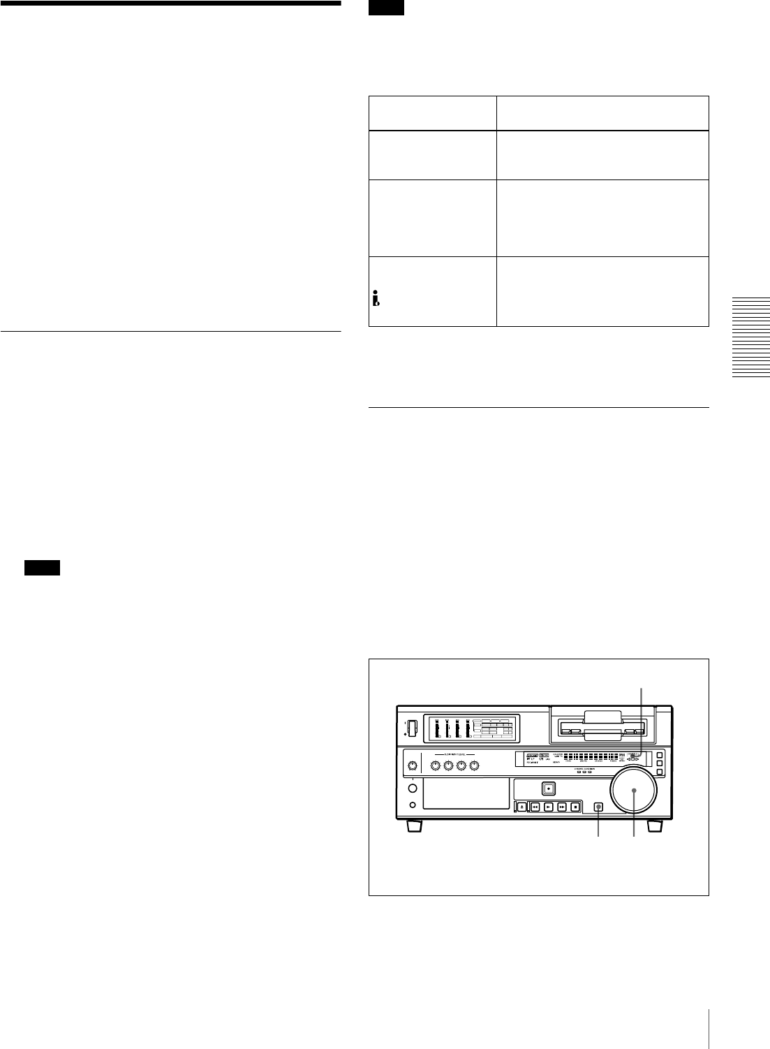
53
High-Speed and Low-Speed Search—Quickly and Accurately Determining Editing Points
Chapter 3 Convenient Functions for Editing Operation
High-Speed and Low-
Speed Search—Quickly
and Accurately
Determining Editing
Points
Use the search function to easily locate the desired scene
and to quickly and accurately determine edit points.
When F. FWD/REW under the AUTO EE SELECT menu
item (see page 63) is set to PB (factory default setting), you
can use the F FWD and REW buttons on this unit or
external equipment for high-speed search.
Search Operations via External
Equipment
You can control the unit in the following operation modes
from an editing control unit (PVE-500, etc.) connected to
the REMOTE connector on the rear panel or from a
SIRCS-compatible remote control unit such as the DSRM-
10 connected to the CONTROL S connector on the front
panel.
Shuttle: Use this mode to view color video playback at
speeds ranging from 0 to 60 times normal speed in
both directions.
Note
When controlling the unit from the DSRM-10 for
shuttle-mode search, the maximum search speed is 16
times normal speed in both directions.
Jog: Use this mode for low-speed search and frame-by-
frame search.
Digital slow: Use this mode for noise-free color video
playback at speeds ranging from 0 to 1/2 times normal
speed in both directions.
Still: Use this mode to view a still picture of any field.
Jog audio: Use this mode to monitor the audio at speeds
ranging from 1 to 1/30 times normal speed in both
directions.
Note
When controlling this unit from external equipment, be
sure to turn on or off the buttons in the remote control
setting section on the front panel of the unit as shown in the
following table.
For description on how to carry out search operations via
external equipment, see the operating instructions for the
equipment.
Search Operations on This Unit
When you perform searching on this unit, be sure to turn
off the REMOTE button on the front panel.
Playing back in jog mode
In jog mode, you can control the speed of playback by the
speed of turning the search dial. The playback speed range
is ±1 times normal speed by factory default. The speed
variation range and pattern can be changed with the JOG
RESPONSE menu item (see page 64).
To carry out playback in jog mode, use the following
procedure.
1Press the SEARCH button or search dial so that the
JOG indicator in the display section is lit.
External equipment Buttons in the remote control
setting section
Editing control unit
connected to the
REMOTE connector
Turn on both the REMOTE and 9PIN
buttons.
SIRCS-compatible
remote control unit
connected to the
CONTROL S
connector
Turn off the REMOTE button.
Equipment
connected to the
DV IN/OUT
connector
Turn on both the REMOTE and
i.LINK buttons.
1 1,2,3
INPUT
VIDEO
AUDIO
V:SDTI SDTI i.LINK
dB
0
-12
-20
-30
-40
-60
dB
0
1
0
-1
-2
OVER
1
dB
0
-12
-20
-30
-40
-60
dB
0
1
0
-1
-2
OVER
2
dB
0
-12
-20
-30
-40
-60
dB
0
1
0
-1
-2
OVER
3
dB
0
-12
-20
-30
-40
-60
dB
0
1
0
-1
-2
OVER
4
REC MODE
CH11/2
CH23/4
COMPOSITE
2CH4CHPB FS
Y-R , B
48k44.1k32k
S VIDEO
SDI SG
ANALOG
AES/EBU
SDI SG
ANALOG
AES/EBU
SDI SG
JOG indicator
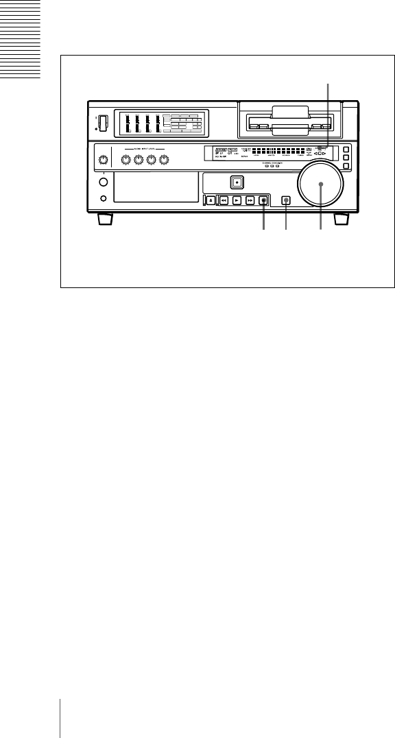
54 High-Speed and Low-Speed Search—Quickly and Accurately Determining Editing Points
Chapter 3 Convenient Functions for Editing Operation
Pressing the search dial toggles between jog mode and
shuttle mode.
2Turn the search dial in the desired direction at the
speed corresponding to the desired playback speed.
Playback in jog mode starts.
3To stop playback in jog mode, stop turning the search
dial.
Playing back in shuttle mode
In shuttle mode, you can control the speed of playback by
the angular position of the search dial. The range of
playback speed is ±32 times normal speed by factory
default. This can be changed with the SHUTTLE menu
item (see page 63). The search dial has detents at the
positions of still image and ±10 times normal speed.
To carry out playback in shuttle mode, use the following
procedure.
1Press the SEARCH button or search dial so that the
SHUTTLE indicator in the display section is lit.
Pressing the search dial toggles between jog mode and
shuttle mode.
2Turn the search dial to the desired angle corresponding
to the desired playback speed.
Playback in shuttle mode starts.
3To stop playback in shuttle mode, return the search
dial to the center position, or press the STOP button.
To return to normal-speed playback
Press the PLAY button.
To alternate between normal-speed playback and
shuttle mode playback
Set the search dial to the position corresponding to the
desired shuttle playback speed, then switch between
normal-speed playback and shuttle playback by pressing
the PLAY and SEARCH buttons alternately.
For intermittent shuttle mode playback, press the STOP
and SEARCH buttons alternately.
3 1 1,2,3
INPUT
VIDEO
AUDIO
V:SDTI SDTI i.LINK
dB
0
-12
-20
-30
-40
-60
dB
0
1
0
-1
-2
OVER
1
dB
0
-12
-20
-30
-40
-60
dB
0
1
0
-1
-2
OVER
2
dB
0
-12
-20
-30
-40
-60
dB
0
1
0
-1
-2
OVER
3
dB
0
-12
-20
-30
-40
-60
dB
0
1
0
-1
-2
OVER
4
REC MODE
CH11/2
CH23/4
COMPOSITE
2CH4CHPB FS
Y-R , B
48k44.1k32k
S VIDEO
SDI SG
ANALOG
AES/EBU
SDI SG
ANALOG
AES/EBU
SDI SG
SHUTTLE indicator
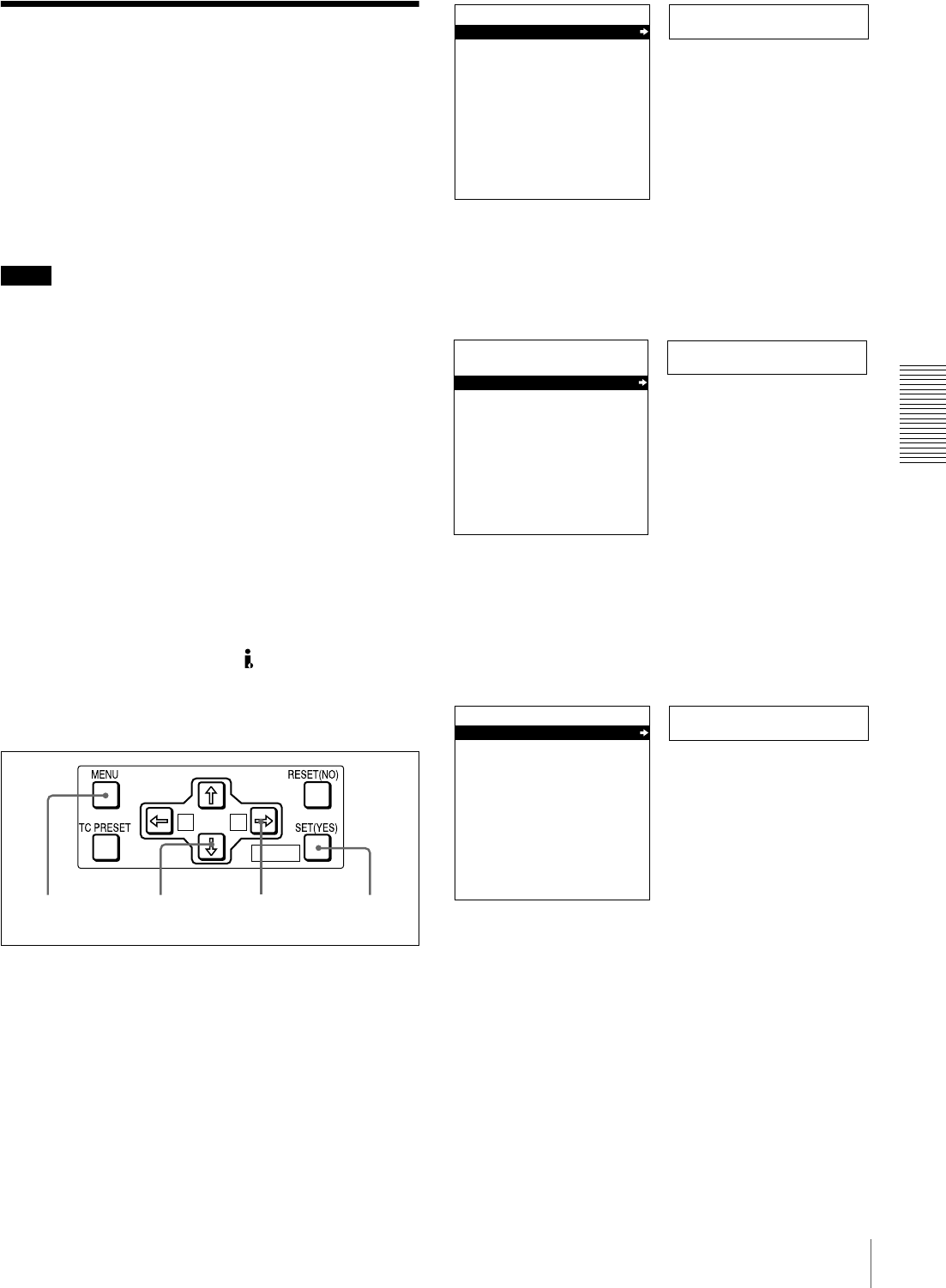
55
Digitally Dubbing Signals in DVCAM Format
Chapter 3 Convenient Functions for Editing Operation
Digitally Dubbing Signals
in DVCAM Format
In addition to straightforward tape dubbing, you can also
use this unit to dub automatically from the beginning of the
tape to the end through the i.LINK interface.
When you dub data recorded by a DVCAM camcorder that
supports the ClipLink function, you can also include the
data stored in the cassette memory.
Notes
• Use a tape recorded in the DVCAM format. A tape
recorded in DV format cannot be used as a source tape
for dubbing through the i.LINK interface.
• Regardless of the audio recording mode setting of this
unit, dubbing is performed with the original audio
recording mode unchanged (two-channel/48 kHz mode
or four-channel/32 kHz mode).
• Approximately the last 2 minutes of the tape may not be
copied because of differences in tape lengths. (If an
index picture is recorded in this portion, it may also not
be copied.)
• A continuous recorded section of approximately 5
seconds is required before the recording start point. It is
recommended to record beforehand color bars or a
similar signal at the start point of the source tape to be
dubbed on this unit.
Connections for dubbing via i.LINK interface
To carry out dubbing through the LINK interface,
connect the i.DV IN/OUT connectors on this unit and the
player.
Use the following procedure.
1Press the MENU button on the menu control panel.
2Press the J or j button to select “AUTO
FUNCTION.”
3Press the k button.
This displays the items in the level 1 of the auto mode
execution menu.
4Press the k button to display the menu level 2 for the
item “i.LINK DUBBING,” and select the data to be
dubbed with the j button.
A B
MARK
1,9 2,4 73,4,5
Setup menu
SYSTEM MENU
SETUP MENU
AUTO FUNCTION
HOURS METER
Monitor screen
Time counter display
Auto func
SYSTEM MENU
SETUP MENU
AUTO FUNCTION
HOURS METER
Monitor screen
Time counter display
i.LINK DUB
AUTO FUNCTION MENU
i.LINK DUBBING
TC INSERT Time counter display
Monitor screen

56 Digitally Dubbing Signals in DVCAM Format
Chapter 3 Convenient Functions for Editing Operation
5Press the k button.
The following message appears.
6Insert the source tape in the player, and the recording
tape in this unit.
A message to confirm the dubbing operation appears.
To cancel the dubbing operation
Press the MENU button.
7Press the SET (YES) button.
The tape is automatically wound back to the
beginning, and dubbing starts.
To end the dubbing operation while it is in progress
Press the STOP button.
When the dubbing is completed, message
“COMPLETED” appears on the monitor screen and
“Completed” in the time counter display.
The source tape and recording tape are both
automatically rewound to the beginning, and the
cassettes ejected. When the cassette is ejected, this unit
returns to the state in step 5.
8To continue by dubbing another tape, repeat steps 6
and 7.
9When the dubbing is completed, press the MENU
button to exit the menu.
If the following message appears in step 6 for an
A/V/TC/CM dubbing operation
When carrying out A/V/TC/CM dubbing, if you insert the
cassettes in step 6, the cassette memory capacity of the
cassettes inserted in both this unit and the player are
checked automatically.
If the cassette memory capacity of the source tape is larger
than that of the recording tape, the above message appears.
In this case, replace the recording tape by a tape with a
larger cassette memory capacity.
>A/V/TC/CM
AUTO FUNCTION MENU
i.LINK DUBBING
A/V
A/V/TC
A/V/TC/CM
Monitor screen
Time counter display
Example: Selecting “A/V/TC/CM”
Set tape!
i.LINK DUBBING
(A/V/TC/CM)
INSERT RECORD TAPE IN
THIS VTR AND SOURCE
TAPE IN THE PLAYER VTR.
ABORT:MENU KEY
Monitor screen
Time counter display
Start dub?
i.LINK DUBBING
(A/V/TC/CM)
START QSDI DUBBING?
START:YES KEY
ABORT:MENU KEY
Monitor screen
Time counter display
Executing
i.LINK DUBBING
(A/V/TC/CM)
EXECUTING.
TCR 00:00:00:00
UBR 00:00:00:00
ABORT:MENU KEY
Monitor screen
Time counter display
CM capacity!
i.LINK DUBBING
(A/V/TC/CM)
CM MEMORY STORAGE
CAPACITY OF THE RECORD
TAPE IS TOO SMALL.
ABORT:MENU KEY
Monitor screen
Time counter display

57
Digitally Dubbing Signals in DVCAM Format
Chapter 3 Convenient Functions for Editing Operation
If the following message appears in step 7 for an
A/V/TC/CM dubbing operation
When carrying out A/V/TC/CM dubbing, if you press the
STOP button to stop dubbing in step 7, or if dubbing stops
because the source tape is longer than the recording tape,
the above message appears to confirm whether or not to
copy the contents of the cassette memory.
To copy the contents of the cassette memory, press the
SET (YES) button.
If you do not wish to copy the contents of the cassette
memory, press the RESET (NO) button. If you press the
RESET (NO) button, however, the contents of the cassette
memory may not agree with the material recorded on the
tape.
Copy CM?
i.LINK DUBBING
(A/V/TC/CM)
SDTI DUBBING IS ABORTED.
EXECUTE CM COPY?
COPY :YES KEY
NOT COPY:NO KEY
Monitor screen
Time counter display

58 Digitally Dubbing Signals in DVCAM Format
Chapter 3 Convenient Functions for Editing Operation

59
Menu Organization
Chapter 4
Menu Settings
Menu Organization
As shown in the following figure, the menu system
consists of four levels and is functionally divided into three
subsystems: the setup menu, the auto mode (AUTO
FUNCTION) execution menu and the digital hours meter
display menu. This chapter mainly describes the setup
menu, showing its contents and how to operate it.
For details of the AUTO FUNCTION menu, see “Digitally
Dubbing Signals in DVCAM Format” on page 55 and
“Rerecording the Time Code—TC Insert Function” on
page 51.
For details of the digital hours meter display, see “Regular
Checks” on page 95.
The items of the setup menu are divided into several
functional groups on level 1, and except for the MENU
GRADE item the settings themselves are made on level 2
or level 3.
Also, the menu items are divided into two categories
according to how frequently they are accessed: the “basic”
items, to which frequent access is normally required, and
the “enhanced” items, which are less frequently used. In
the following figure, the items shown in boldface are basic
items, and the other items are enhanced items.
The menu settings are saved in non-volatile memory,
which means they are not erased when you power off the
unit after executing the setting operation.
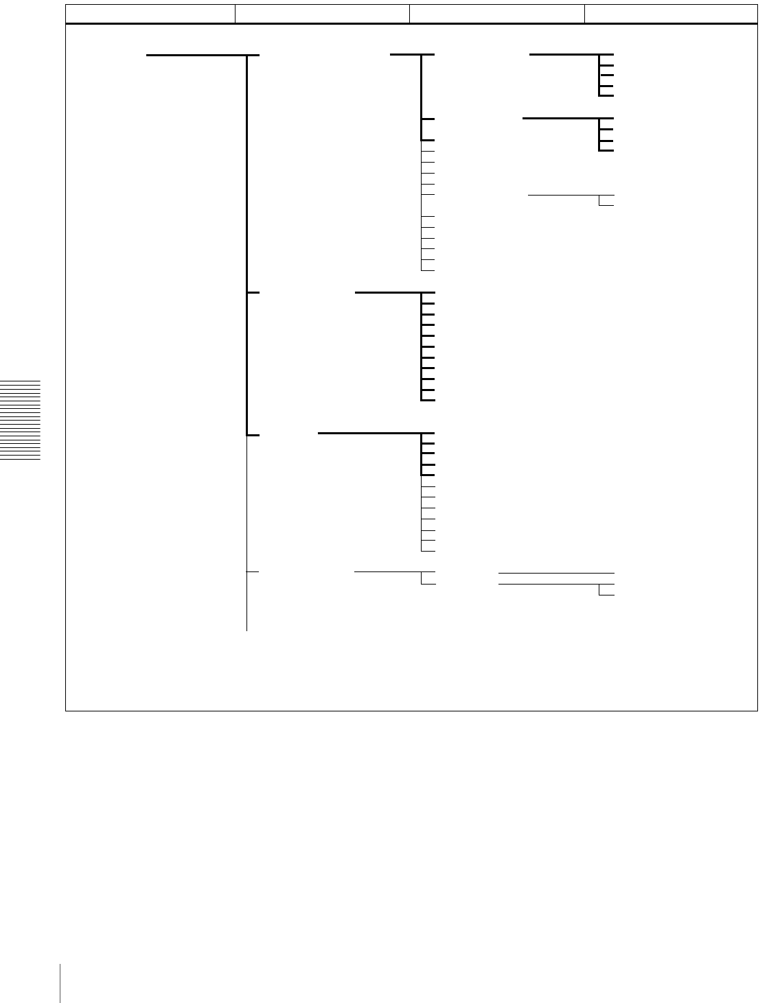
60 Menu Organization
Chapter 4 Menu Settings
Menu organization
OPERATIONAL FUNCTION REPEAT FUNCTION
AUTO EE SELECT
LOCAL ENABLE
REC INHIBIT
A1 EDIT CH
A2 EDIT CH
SEARCH ENABLE
MAX SRCH SPEED
JOG RESPONSE
PREROLL TIME
AFTER CUE-UP
PLAY START
AUTO REW
A MODE CHANGE
CHARA. DISPLAY
CHARA. POSITION
CHARA. TYPE
CHARA. VSIZE
DISPLAY INFO
SUB STATUS
MENU DISPLAY
PEAK HOLD
OVER DISP HOLD
BRIGHTNESS
ALARM
TC MODE
RUN MODE
DF MODE a)
TC SELECT
VITC
TCG REGEN
UB BINARY GP.
VITC POS SEL-1
VITC POS SEL-2
VITC OUTPUT
EE OUT PHASE
MUTE IN SRCH
REPEAT MODE
REPEAT TOP
REPEAT END
A PRESET
B PRESET
CASSETTE OUT
F.FWD/REW
STOP
STANDBY OFF
DISPLAY CONTROL
TAPE PROTECTION STOP TIMER
STILL TIMER
NEXT MODE
TIME CODE
SETUP MENU
FROM STOP
FROM STILL
SHUTTLE
F.FWD/REW
Level 1 Level 2 Level 3Menu selection level
(Continued)
a) Menu item for DSR-1800A only
61
Menu Organization
Chapter 4 Menu Settings
VIDEO CONTROL
AUDIO CONTROL
MENU GRADE
CONTROL DEV
C PHASE MODE
ADJ RANGE
VIDEO GAIN
CHROMA GAIN
CHROMA PHASE
SETUP LEVEL
a)
BLACK LEVEL
b)
LINE 335
REF LEVEL
CH1 IN LEVEL
CH2 IN LEVEL
CH3 IN LEVEL
CH4 IN LEVEL
OUTPUT LEVEL
i.LINK DUBBING
TC INSERT
T1:OPERATION
T2:DRUM ROTATION
T3:TAPE RUNNING
CT:THREADING
HOURS METER
A/V
A/V/TC
A/V/TC/CM
AUTO FUNCTION
STILL MODE
EE DELAY
INT VIDEO SG
STD/NON-STD
OUT REF SEL
SETUP REMOVE
a)
SETUP ADD
a)
CC(F1) BLANK
a)
CC(F2) BLANK
a)
WIDE MODE
ESR MODE
PROCESS CONTROL
REC MODE
INPUT ARRANGE
REC LEVEL
LEVEL SELECT
INT AUDIO SG
OUTPUT CH3/4
OUTPUT PHASE
JOG CONTROL
SHUTTLE MUTE
AUDIO EDIT
DV PB ATT
DIGITAL PROCESS
SETUP BANK OPERATION
SYSTEM EE MODE
RECALL BANK1
RECALL BANK2
RECALL BANK3
RECALL BANK4
SAVE BANK 1
SAVE BANK 2
SAVE BANK 3
SAVE BANK 4
INPUT BLANK
b)
Level 1 Level 2 Level 3Menu selection level
(Continued)
a) Menu item for DSR-1800A only
b) Menu item for DSR-1800AP only
62 Menu Contents
Chapter 4 Menu Settings
Menu Contents
Setup Menu
The purpose and settings of the setup menu items are
described below.
Indications of menu items and settings
In the table below entitled “Menu contents,” the indication
of each menu item or setting on the monitor screen is
shown first, then the indication of the same item or setting
in the time counter display of this unit is shown in square
brackets ([ ]). • Settings preceded by an asterisk (such as *EE) are
factory default settings.
• In the time counter display, one to three “>” symbols
may precede item or setting indications depending on the
current menu level. Larger numbers of “>” symbols
indicate lower menu levels.
Menu contents
Examples:
Indication on monitor
screen Indication in time counter
display
OPERATIONAL FUNCTION [Operational]
CASSETTE OUT [>> Cass. out]
*EE [>>> EE]
OPERATIONAL FUNCTION [Operational]: Operation
settings Description of settings
REPEAT FUNCTION [>REP
FUNC]: Make settings for
repeat playback mode.
REPEAT MODE
[>>REPEAT MD]:
Determine whether or
not to put the unit into
repeat playback mode.
*OFF [>>> OFF]: Do not put the unit into repeat playback
mode.
ON [>>> ON]: Put the unit into repeat playback mode.
ON (FREEZE) [>>> FREEZE]: Put the unit into freeze
playback mode. In this case, while the unit is cueing up to
the repeat start point, the freeze picture of the repeat end
point is displayed.
REPEAT TOP [>>REP
TOP]: Determine
whether the repeat
start point is the
beginning of tape or
point A.
*TAPE TOP [>>>Tape top]: The repeat start point is the
beginning of tape.
A POINT [>>>A point]: The repeat start point is point A as set
by the user.
REPEAT END [>>REP
END]: Determine
whether the repeat end
point is the end of the
video recorded portion,
the end of tape or point
B.
*VIDEO END [>>>VD end]: The repeat end point is the end
of the video recorded portion.
TAPE END [>>>Tape end]: The repeat end point is the end of
tape.
B POINT [>>>B point]: The repeat end point is point B as set
by the user.
A PRESET [>>A preset]:
Specify a time code
value to be used as the
setting of point A.
For details, see “Setting Points A and B for Repeat Playback”
on page 40.
B PRESET [>>B preset]:
Specify a time code
value to be used as the
setting of point B.
For details, see “Setting Points A and B for Repeat Playback”
on page 40.
63
Menu Contents
Chapter 4 Menu Settings
AUTO EE SELECT [> Auto EE]:
Determine whether the unit
enters EE mode or PB mode
when audio and video
signals from other equipment
are input.
When this unit is used as the
recorder for cut editing, it is
possible to output the input
audio and video signals to
the monitor. This enables
editing operation to be
carried out using a single
monitor.
CASSETTE OUT [>>
Cass. out]: Operations
when the cassette has
been ejected
*EE [>>> EE]: Output video and audio signals received from
other equipment.
PB [>>> PB]: Mute video and audio signals.
F. FWD/REW [>> F. FWD/
REW]: Operations
when in fast forward or
rewind mode
EE [>>> EE]: Output video and audio signals received from
other equipment.
*PB [>>> PB]: The unit enters playback mode and outputs a
playback video signal. Audio signals are muted.
STOP [>> STOP]:
Operations when in
stop mode
EE [>>> EE]: Output video and audio signals received from
other equipment.
*PB [>>> PB]: The unit enters playback mode and outputs a
still picture.
STANDBY OFF [>> STBY
OFF]: Operations
when in standby off
mode
EE [>>> EE]: Output video and audio signals received from
other equipment.
*PB [>>> PB]: The unit enters playback mode and outputs a
still picture.
LOCAL ENABLE [> Local ENA]: Select which of the tape
transport control buttons (EJECT, REW, PLAY, F FWD,
STOP, and REC) operate when the REMOTE button is lit.
ALL DISABLE [>> All DIS]: All of the tape transport control
buttons are disabled.
*STOP & EJECT [>> STOP & EJ]: Only the STOP and
EJECT buttons are enabled.
ALL ENABLE [>> All ENA]: All of the tape transport control
buttons are enabled, and settings such as preroll time
change or time data display selection are effective.
REC INHIBIT [>REC INH]: Determine whether to prohibit
recording on tape.
*OFF [>> OFF]: Do not prohibit recording on tape.
ON [>> ON]: Prohibit recording on tape. (The REC INHIBIT
indicator on the front panel lights.)
A1 EDIT CH [> A1 Edit CH]: Determine which audio channel
the EDIT PRESET command set on an editing control unit
(such as the PVE-500) for A1 is assigned to.
*CH-1 [>> CH-1]: Assign to channel 1.
CH-2 [>> CH-2]: Assign to channel 2.
CH-3 [>> CH-3]: Assign to channel 3.
CH-1 & CH-2 [>> CH-1&2]: Assign to channel 1 and channel
2.
A2 EDIT CH [> A2 Edit CH]: Determine which audio channel
the EDIT PRESET command set on an editing control unit
(such as the PVE-500) for A2 is assigned to.
*CH-2 [>> CH-2]: Assign to channel 2.
CH-3 [>> CH-3]: Assign to channel 3.
CH-4 [>> CH-4]: Assign to channel 4.
CH-3 & CH-4 [>> CH-3&4]: Assign to channel 3 and channel
4.
SEARCH ENABLE [>Search ENA]: Select how the unit enters
the search mode.
*DIAL DIRECT [>> DIAL]: Press the SEARCH button or,
except during recording or editing, turn the search dial.
VIA SEARCH KEY [>> via KEY]: Press the SEARCH button.
MAX SRCH SPEED [>Max
SRCH]: Specify the
maximum tape speed in
search mode (shuttle) and
F.FWD (fast forward)/REW
(rewind) mode.
SHUTTLE [>>SHUTTLE]:
Specify the maximum
tape speed in search
mode (shuttle).
X60 [>>> X60]: Maximum 60 times normal speed
*X32 [>>> X32]: Maximum 32 times normal speed
X16 [>>> X16]: Maximum 16 times normal speed
F.FWD/REW [>>F.FWD/
REW]: Specify the
maximum tape speed
in F.FWD/REW mode.
MAX [>>> MAX]: No maximum tape speed is specified.
*X85 [>>> X85]: Maximum 85 times normal speed
X60 [>>> X60]: Maximum 60 times normal speed
X32 [>>> X32]: Maximum 32 times normal speed
Note
When this item is set to MAX, the playback video signal is
muted.
OPERATIONAL FUNCTION [Operational]: Operation
settings Description of settings
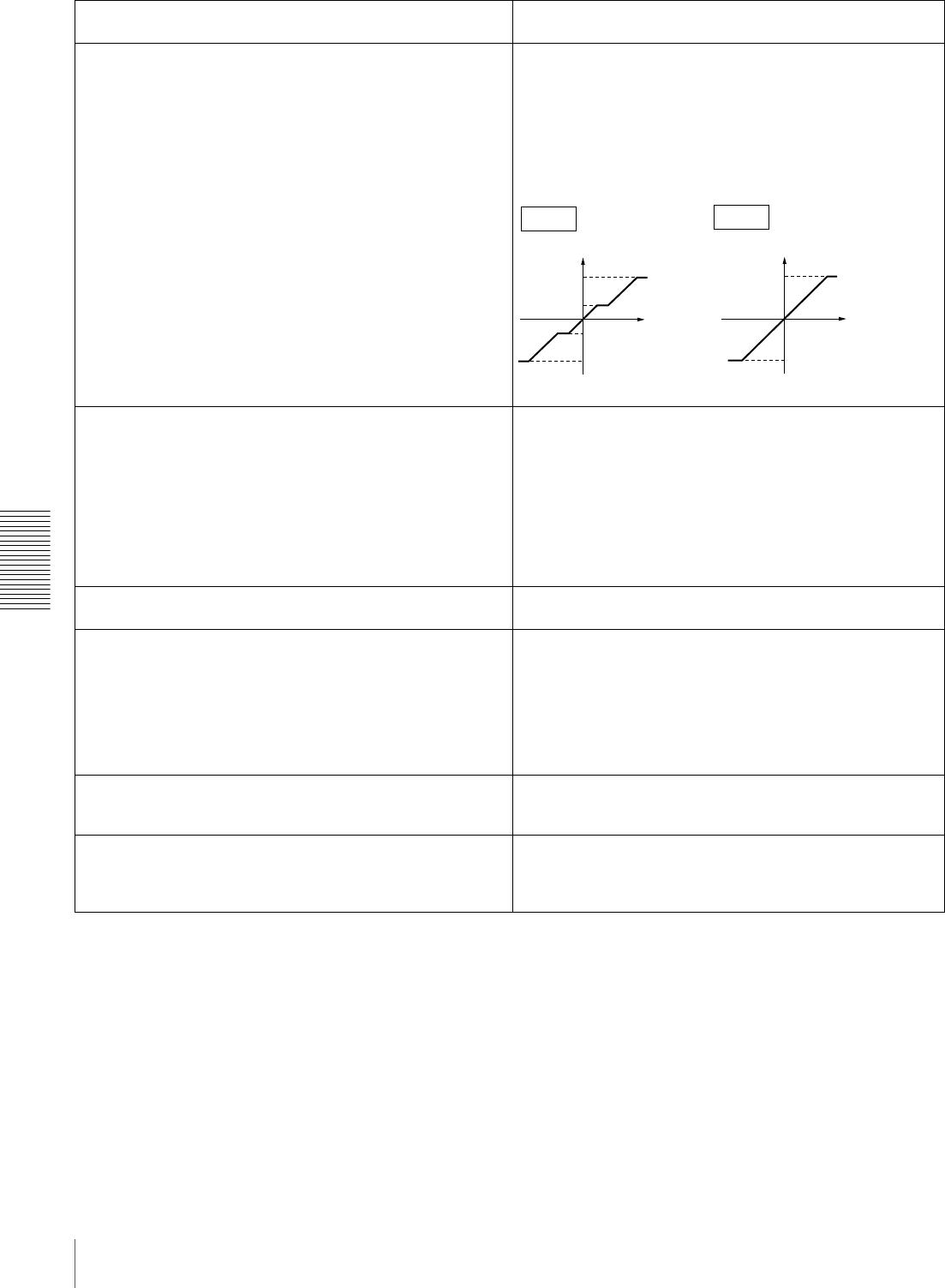
64 Menu Contents
Chapter 4 Menu Settings
JOG RESPONSE [>JOG dial]: Select the tape speed
characteristics for the search dial rotation rate in jog mode.
*TYPE1 (-1 to +1) [>> type 1]: Tape speed varies linearly
over the range −1 to +1.
TYPE2 (-3 to +3) [>> type 2]: Tape speed varies stepwise as
shown in the figure below over the range −3 to +3.
(Characterized by a zone around −1 and +1 where the
tape speed is independent of the rotation rate)
TYPE3 (-3 to +3) [>> type 3]: Tape speed varies linearly over
the range −3 to +3, as shown in the figure below.
PREROLL TIME [> Preroll]: Set the preroll time. 0 SEC [>> 0 sec] to 15 SEC [>> 15 sec]: The preroll time
can be set in one-second increments to between 0 and 15
seconds.
A preroll time of at least 5 seconds is recommended when
using this unit for editing. When an editing control unit such as
the PVE-500 has been connected, this setting is disabled and
the setting on the editing control unit is in effect. Operations
such as the preroll time setting and the time data switching
operation are also performed on the editing control unit.
Factory default setting: 5 SEC [>> 5 sec]
AFTER CUE-UP [> After CUE]: Select the operating mode
following cue-up.
*STOP [>> STOP]: Stop mode
STILL [>> STILL]: Output still pictures in search mode.
PLAY START [> PLAY start]: Set the timing for switching from
stop mode to playback mode.
In an editing system including an editing control unit such as
the PVE-500, you can adjust this setting so that the delay
before switching to playback mode is the same on all the decks
of the editing system. It is then no longer necessary to
synchronize the decks for editing, and the preroll time can be
shortened.
16 FRAME DELAY [>> 16 delay] to 4 FRAME DELAY
[>> 4 delay]: The larger the numerical value, the
longer the delay. By adjusting this setting, it is
possible to reduce the phase synchronization time
and preroll time during editing.
Factory default setting: 5 FRAME DELAY [>> 5 delay] (for
DSR-1800A) or 4 FRAME DELAY [>> 4 delay] (for DSR-
1800AP)
AUTO REW [>Auto REW]: Select whether to rewind the tape
automatically when recording or playback reaches the end
of a tape.
DISABLE [>> DISABLE]: Do not rewind the tape
automatically.
*ENABLE [>> ENABLE]: Rewind the tape automatically.
A MODE CHANGE [>Aud change]: Determine whether or not
to permit an insert editing that uses a different audio
recording mode (2- or 4-channel mode) from that which
was used for the tape loaded in the recorder.
*OFF [>> OFF]: Do not permit.
ON [>> ON]: Permit.
OPERATIONAL FUNCTION [Operational]: Operation
settings Description of settings
+3
+1
-1
-3
FWD
FWD
RVS
RVS
+3
-3
FWD
FWD
RVS
RVS
TYPE3
TYPE2
Speed Speed
Rotation rate
Rotation rate

65
Menu Contents
Chapter 4 Menu Settings
DISPLAY CONTROL [Display]: Settings related to
indications on the monitor and the unit Description of settings
CHARA. DISPLAY [> Chara disp]: Determine whether or not
to output text (such as time code values) from the VIDEO
OUT 2 (SUPER) connector.
OFF [>> OFF]: Do not output text. (In spite of this setting,
pressing the MENU button causes menu text to be
output.)
*ON [>> ON]: Output text.
CHARA. POSITION [> Chara pos]: Set the position of text
superimposed on output from the VIDEO OUT 2 (SUPER)
connector to the monitor.
Use JjK k buttons on the menu control panel to adjust the
text position while watching the monitor screen.
To return to the level 1 of the setup menu, press the MENU
button.
CHARA. TYPE [> Chara type]: Set the type of characters in
text superimposed on output from the VIDEO OUT 2
(SUPER) connector to the monitor.
Make the following settings while watching the monitor screen.
*WHITE (WITH BKGD) [>> White]: White characters on black
background
BLACK (WITH BKGD) [>> Black]: Black characters on white
background
WHITE/OUTLINE [>> W/outline]: White characters with black
outline
BLACK/OUTLINE [>> B/outline]: Black characters with white
outline
CHARA. VSIZE [>Chara size]: Determine the vertical size of
characters such as time code output from the VIDEO OUT
2 (SUPER) connector for superimposed display on the
monitor.
Make the selection while watching the monitor screen.
*×1 [>> ×1]: Standard size
×2 [>> ×2]: 2 times standard size
DISPLAY INFO [> DISP info]: Select information
superimposed on output from the VIDEO OUT 2 (SUPER)
connector to the monitor.
*TIME DATA & STATUS [>> Time&STA]: Time data and
operating mode indications
TIME DATA & UB [>> Time&UB]: Time data selected using
the COUNTER SEL button, and user bit data (When user
bit data is selected using the COUNTER SEL button, user
bit data and time code are shown.)
TIME DATA & CNT [>> Time&CNT]: Time data selected
using the COUNTER SEL button, and CNT value (When
CNT is selected using the COUNTER SEL button, CNT
value and time code are shown.)
TIME DATA & TIME[>> Time&Time]: Time data and VITC
TIME DATA ONLY [>> Time]: Time data only
REC DATE & TIME [>> REC Date]: The time data selected
with the COUNTER SEL button is shown in the time
counter display, and the date and time of recording are
shown on the monitor screen.
SUB STATUS [> Sub status]: Select supplementary status
information superimposed on output from the VIDEO OUT
2 (SUPER) connector to the monitor.
*OFF [>> OFF]: Nothing of supplementary status information
EDIT PRESET [>> Edit pre]: Indications of the editing mode
settings made from the connected editing control unit
TC MODE [>> TC mode]: Indications of the operating mode
of internal time code generator
REMAIN [>> Remain]: Remaining capacity of the tape
AUDIO MIXING [>> Aud Mix]: Indications of input audio
mixing
ALL [>> ALL]: All of the above-mentioned items of
supplementary status information
For details of supplementary status information displayed on
the monitor when a setting other than OFF is selected, see
“Displaying Supplementary Status Information” on page 80.
MENU DISPLAY [> Menu DISP]: Set the type of characters in
menu text superimposed on output from the VIDEO OUT 2
(SUPER) connector to the monitor.
Make the following settings while watching the monitor screen.
*WHITE (WITH BKGD) [>> White]: White characters on black
background
BLACK (WITH BKGD) [>> Black]: Black characters on white
background
WHITE/OUTLINE [>> W/outline]: White characters with black
outline
BLACK/OUTLINE [>> B/outline]: Black characters with white
outline
66 Menu Contents
Chapter 4 Menu Settings
PEAK HOLD [>Peak hold]: Set the peak hold time for the
audio level meters.
OFF [>> OFF] to 1.5 SEC [1.5 sec]: Set the peak hold time in
the range of OFF (no peak hold) to 1.5 seconds in 0.1
second steps.
Factory default setting: OFF [>> OFF]
OVER DISP HOLD [> Hold OVER]: Determine whether or not
to hold the OVER indication display on the audio level
meters once the indications light.
*OFF [>> OFF]: Do not hold the OVER indication display.
ON (HOLD) [>> ON]: Hold the OVER indication display.
Note
With ON selected, once the display is held it will remain held
unless you change the setting to OFF.
BRIGHTNESS [> Brightness]: Set the brightness of front
panel indicators.
Set brightness as a percentage of the maximum.
100% [>> 100%]
*75% [>> 75%]
50% [>> 50%]
ALARM [> ALARM]: Determine whether alarm messages are
issued or not.
OFF [>> OFF]: Alarm messages are not issued.
*ON [>> ON]: Alarm messages are issued.
TIME CODE [Time code]: Settings related to the time code
generator Description of settings
TC MODE [> TC mode]: Determine the time code to use:
internal time code using a preset initial value, regenerated
internal time code (locked to time code read from tape), or
external time code.
*INT PRESET [>> PRESET]: Use internal time code with a
preset initial value.
INT REGEN [>> REGEN]: Use internal time code locked to
time code read from tape.
EXT REGEN [>> EXT]: Use external time code selected as
follows.
• When TC is selected
External time code input to the TIME CODE IN
connector
• When VITC is selected
The VITC time code present in the input video signal
Note
When the selected input mode is i.LINK (the i.LINK indicator is
lit in the Input selection/audio mode display section), setting
this item to EXT REGEN causes the internal time code
generator to automatically synchronize with the external time
code input to the unit via the i.LINK interface.
RUN MODE [> RUN mode]: Select the advancement (RUN)
mode of the time code generator.
*FREE RUN [>> FREE RUN]: Time code generator keeps
running.
REC RUN [>> REC RUN]: Time code generator only runs
while recording.
Note
Set to FREE RUN when carrying out editing with an editing
control unit. With the REC RUN setting, editing will not be
carried out correctly.
(For DSR-1800A only)
DF MODE [> DF mode]: Select whether the time code
generator and time counter operate in drop frame mode or
non-drop frame mode.
Normally select drop frame mode, to keep in
synchronization with real time. The non-drop frame mode
is useful for example when using computer graphics, and
working on a frame count basis.
*ON (DF) [>> ON (DF)]: Drop frame mode
OFF (NDF) [>> OFF (NDF)]: Non-drop frame mode
TC SELECT [>TC select]: Determine which to display in the
time counter display, TC or VITC.
VITC [>> VITC]: Display VITC.
*TC [>> TC]: Display TC.
DISPLAY CONTROL [Display]: Settings related to
indications on the monitor and the unit Description of settings

67
Menu Contents
Chapter 4 Menu Settings
VITC [> VITC]: Determine whether to record the internally
generated time code as VITC.
OFF [>> OFF]: Do not record the internally generated time
code as VITC. (VITC present in the input video signal is
recorded unchanged.)
*ON [>> ON]: Record the internally generated time code as
VITC.
TCG REGEN [>TCG regen]: Select the signal to be
regenerated when the time code generator is in the
regeneration mode (i.e., when the TC MODE menu item is
set to INT REGEN or EXT REGEN).
*TC & UB [>> TC & UB]: Both the time code and user bits are
regenerated.
TC [>> TC]: Only the time code is regenerated.
UB [>> UB]: Only the user bits are regenerated.
UB BINARY GP. [> Binary Gp.]: Select the user bit binary
group flag of the time code generator.
Note
When the TC MODE menu item is set to EXT REGEN, the
user-bit binary group flag setting follows the setting on the time
code input to this unit.
*000: NOT SPECIFIED [>> 000]: Character set not specified
001: ISO CHARACTER [>> 001]: 8-bit characters conforming
to ISO 646 and ISO 2022
010: UNASSIGNED-1 [>> 010]: Undefined
011: UNASSIGNED-2 [>> 011]: Undefined
100: UNASSIGNED-3 [>> 100]: Undefined
101: PAGE/LINE [>> 101]: Multiplex
110: UNASSIGNED-4 [>> 110]: Undefined
111: UNASSIGNED-5 [>> 111]: Undefined
VITC POS SEL-1 [>VITC pos-1]: Select a line to insert the
VITC in.
Note
You can insert the VITC signal in two places. To insert it in two
places, set both this item and also VITC POS SEL-2.
(For DSR-1800A)
12 LINE [>> 12 line] to 20 LINE [>> 20 line]: Select any line
from 12 to 20.
Factory default setting: 16 LINE [>> 16 line]
(For DSR-1800AP)
Select a line to insert the VITC in.
9 LINE [>> 9 line] to 22 LINE [>> 22 line]: Select any line
from 9 to 22.
Factory default setting: 19 LINE [>> 19 line]
VITC POS SEL-2 [>VITC pos-2]: Select a line to insert the
VITC in.
Note
You can insert the VITC signal in two places. To insert it in two
places, set both this item and also VITC POS SEL-1.
(For DSR-1800A)
12 LINE [>> 12 line] to 20 LINE [>> 20 line]: Select any line
from 12 to 20.
Factory default setting: 18 LINE [>> 18 line]
(For DSR-1800AP)
Select a line to insert the VITC in.
9 LINE [>> 9 line] to 22 LINE [>> 22 line]: Select any line
from 9 to 22.
Factory default setting: 21 LINE [>> 21 line]
VITC OUTPUT [>VITC out]: Select the time code to be output
as VITC.
OFF [>> OFF]: Do not output VITC.
TC [>> TC]: Output TC after converting it into VITC.
*VITC [>> VITC]: Output VITC.
EE OUT PHASE [>EE out]: Determine the output phase for
the LTC signal output from the TIME CODE OUT
connector when recording time code and in STOP REC
mode (forced EE mode).
*MUTE [>>mute]: Mute the output.
THROUGH [>> through]: Output the time code input to the
TIME CODE IN connector as it is. (See example
configuration on page 73.)
VIDEO INPUT PHASE [>> V input]: Output the time code
with the same phase as the input video signal phase.
(See example configuration on page 73.)
VIDEO OUTPUT PHASE [>> V output]: Output the time code
with the same phase as the output video signal phase.
(See example configuration on page 74.)
MUTE IN SRCH [>Mute in SR]: Select whether to mute the
output from the TIME CODE OUT connector in search
(jog/shuttle) mode.
OFF [>> OFF]: Do not mute.
*ON [>> ON]: Mute.
TIME CODE [Time code]: Settings related to the time code
generator Description of settings
68 Menu Contents
Chapter 4 Menu Settings
TAPE PROTECTION [Tape protct]: Settings related to tape
and video head protection Description of settings
FROM STOP [> From STOP]:
Set the time to switch from
stop mode to tape protection
mode.
STOP TIMER [>> STP
timer]: Set the time to
switch from stop mode
to tape protection
mode.
5 MIN [>>> 5 min] to 0.5 SEC [>>> 0.5 sec]: Select time from
12 settings ranging from 0.5 second to 5 minutes in steps
of 0.1 second.
Factory default setting: 1MIN [>>> 1min]
Note
If the value is set to 1 minute or more, the unit enters internal
protection mode in 1 minute, which makes start up slower.
FROM STILL [> From STILL]:
Set the time to switch from
still search mode to tape
protection mode. Also select
the type of tape protection
mode.
STILL TIMER [>> STL
timer]: Set the time to
switch from still search
mode to tape
protection mode.
5 MIN [>>> 5 min] to 0.5 SEC [>>> 0.5 sec]: Select time from
12 settings ranging from 0.5 second to 5 minutes in steps
of 0.1 second.
Factory default setting: 1MIN [>>> 1min]
Note
If the value is set to 1 minute or more, the unit enters internal
protection mode in 1 minute, which makes start up slower.
NEXT MODE [>> Next
mode]: Select the type
of tape protection
mode to follow still
search mode when the
time set with the STILL
TIMER menu item
elapses.
*STEP FWD [>>> Step]: The tape is advanced at 1/30 times
normal speed for about 2 seconds.
STANDBY OFF [>>> STANDBY]: Standby off mode
Note
The Step setting is enabled only when “STILL TIMER” is set to
less than 1 minute.
VIDEO CONTROL [Video]: Settings related to video control Description of settings
STILL MODE [> STILL mod]: Select the image to output in
still image mode.
*AUTO [>> Auto]: Output field 1 or field 2 as the still image,
according to the position the tape is stopped.
FRAME [>> Frame]: Output a full frame as the still image.
FIELD1 [>> Field 1]: Output only field 1 as the still image.
FIELD2 [>> Field 2]: Output only field 2 as the still image.
EE DELAY [>EE delay]: An E-E video signal is output delayed
with respect to the video input signal by the time for video
circuit processing. With this item, select whether or not to
delay the sync signal attached to the output video signal by
an amount corresponding to the video signal delay.
*SYNC DELAY [>> sync]: Delay the sync signal by the
corresponding amount of time before attaching it.
VIDEO DELAY [>> video]: Attach a sync signal with the same
timing as the input signal.
INT VIDEO SG [>Video SG]: Select the test signal to be
output from the internal test signal generator. When SG is
selected using the VIDEO IN button, the internal test signal
generator outputs the selected test signal. This signal can
be recorded.
*75% COLOR BARS [>>75% bars]: 75% color bar signal
BLACK BURST [>>BB]: Black burst signal
STD/NON-STD [>STD/N-STD]: Select the STD or NON-STD
mode in accordance with the composite video or S-video
input.
*FORCED STD [>> STD]: The STD mode is always used
(forced STD mode).
FORCED NON-STD [>> NON-STD]: Use this setting when
the input video signal is unstable (forced NON-STD
mode).
OUT REF SEL [>Out Ref.]: Select the reference video signal
to use.
*REF VIDEO [>> REF]: Use the signal input to a REF. VIDEO
IN connector as the reference video signal. The input
video signal to be edited is required to be in
synchronization with the reference video signal.
INPUT VIDEO [>> INPUT]: Use the input video signal
selected with the VIDEO IN button in the INPUT SELECT
section.
(For DSR-1800A only)
SETUP REMOVE [> Setup rmv]: Determine whether or not to
remove black setup (7.5 IRE) from input analog video
signals when converting them into digital signals.
*OFF [>> OFF]: Do not remove black setup.
ON (REMOVE) [>> ON]: Remove black setup.
(For DSR-1800A only)
SETUP ADD [> Setup add]: Determine whether or not to add
black setup to analog video output signals.
*OFF [>> OFF]: Do not add black setup.
ON (ADD) [>> ON]: Add black setup.
69
Menu Contents
Chapter 4 Menu Settings
(For DSR-1800A only)
CC(F1) BLANK [>CC1 blank]: Select whether to mute the
closed caption signal to be superimposed on the 1st field
of the output video signal.
*OFF [>> OFF]: Do not mute.
ON [>> ON]: Mute.
(For DSR-1800A only)
CC(F2) BLANK [>CC2 blank]: Select whether to mute the
closed caption signal to be superimposed on the 2nd field
of the output video signal.
*OFF [>> OFF]: Do not mute.
ON [>> ON]: Mute.
WIDE MODE [>Wide mode]: Determine whether to retain
wide-screen aspect ratio information accompanying video
being recorded or played back.
*AUTO [>> Auto]: When video being recorded or played back
is accompanied by wide-screen aspect ratio information,
retain the information.
OFF [>> OFF]: Ignore wide-screen aspect ratio information.
ON [>> ON]: Whenever recording or playing back video, retain
wide-screen aspect ratio information.
ESR MODE [>ESR mode]: Select whether to enable the edge
subcarrier reducer (ESR).
*OFF [>> OFF]: Do not enable.
ON [>> ON]: Enable.
When playing back a composite signal, set this to ON.
PROCESS CONTROL [>Proc
ctrl] CONTROL DEV [>>Ctrl
dev]: Select the
method of controlling
the internal digital
video processor.
*REMOTE [>>>REMOTE]: Use an optional remote control
unit to control the internal digital video processor.
MENU [>>> MENU]: Use the setup menu to change the
settings for the internal digital video processor.
C PHASE MODE [>>C
Phas MD]: Select the
phase rotation mode
for chroma phase
control.
The effect of this setting
applies to the output levels
of all of the composite
video, S video, SDI and
component video signals.
*U/V (COMPOSITE) [>>> Cmpst]: Select this setting when
observing the composite video output level using a
composite vectorscope.
PB/PR (COMPONENT) [>>> Cmpnt]: Select this setting
when observing the component video output level using a
component vectorscope.
ADJ RANGE [>>Adj
range]: Select the
variable range of the
VIDEO and CHROMA
gains.
*−3 to +3 (dB) [>>> −3/+3]: −3 dB to +3 dB
WIDE [>>> wide]: −∞ to +3 dB
VIDEO GAIN [>>V gain]:
Adjust the video output
level.
00H to 3FFH
Factory default setting: 200H
CHROMA GAIN [>>C
gain]: Adjust the
chroma output level.
00H to 3FFH
Factory default setting: 200H
CHROMA PHASE [>>C
phase]: Adjust the
chroma phase.
00H to FFH
Factory default setting: 80H
(For DSR-1800A only)
SETUP LEVEL [>>Setup
lev]: Adjust the black
setup level.
00H to 3FFH
Factory default setting: 200H
(For DSR-1800AP only)
BLACK LEVEL [>>Black
lev]: Adjust the black
level.
00H to 3FFH
Factory default setting: 200H
(For DSR-1800AP only)
INPUT BLANK [>Input blnk] LINE 335 [>>Line 335]:
Switch blanking on or
off for the 335th line of
the input video signal.
BLANK [>>> blank]: Blank.
THROUGH [>>> through]: Do not blank.
VIDEO CONTROL [Video]: Settings related to video control Description of settings
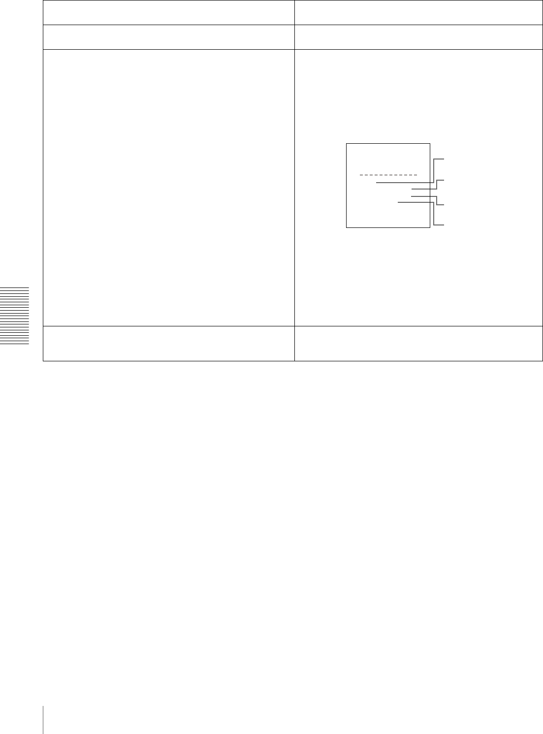
70 Menu Contents
Chapter 4 Menu Settings
AUDIO CONTROL [Audio]: Settings related to audio
control Description of settings
REC MODE [>REC mode]: Select the audio recording mode. *2CHANNEL (48kHz) [>> 2 ch]: 2-channel, 48-kHz mode
4CHANNEL (32kHz) [>> 4 ch]: 4-channel, 32-kHz mode
INPUT ARRANGE [>Input arng]: Make settings for input
audio mixing.
Set the channels on which to record the input audio signals as
follows.
(1) Use the KkJj buttons to move the cursor and the SET
(YES) button to toggle the setting on and off.
(2) To save the settings, press the MENU button to return to
the previous screen, then press the SET (YES) button.
Example settings:
REC LEVEL [>Rec level]: Determine whether to enable or
disable the AUDIO INPUT LEVEL control knobs on the
front panel.
*VARIABLE [>> Variable]: Enable.
PRESET [>> Preset]: Disable.
AUDIO INPUT SOURCE
ARRANGE
in1 in2 in3 in4
ch1:*on
ch2: on on
ch3: on
ch4 on
ON/OFF : SET KEY
TO MENU : MENU KEY
1
2
3
4
1 Input audio channel 1 (“in1”) is recorded on audio channel 1
(“ch1”) on tape.
2 Input audio channels 2 and 4 (“in2” and “in4”) are recorded
mixed on audio channel 2 (“ch2”) on tape.
3 Input audio channel 4 (“in4”) is recorded on audio channel 3
(“ch3”) on tape.
4 Input audio channel 3 (“in3”) is recorded on audio channel 4
(“ch4”) on tape.

71
Menu Contents
Chapter 4 Menu Settings
LEVEL SELECT [>Level Sel] REF LEVEL [>>REF
Level]: Select the
audio reference level
(headroom) for
recording on tape.
*−20 dB [>>> −20dB] (factory default setting for DSR-1800A)
*−18 dB [>>> −18dB] (factory default setting for DSR-
1800AP)
−16 dB [>>> −16dB]
−12 dB [>>> −12dB]
CH1 IN LEVEL [>>CH1
input]: Select the
audio level setting
according to the audio
level of the signal input
to the AUDIO IN CH-1
connector.
*+4 dBm [>>> +4dBm]
0 dBm [>>> 0dBm]
−3 dBm [>>> −3dBm] (for DSR-1800AP only)
−6 dBm [>>> −6dBm]
CH2 IN LEVEL [>>CH2
input]: Select the
audio level setting
according to the audio
level of the signal input
to the AUDIO IN CH-2
connector.
*+4 dBm [>>> +4dBm]
0 dBm [>>> 0dBm]
−3 dBm [>>> −3dBm] (for DSR-1800AP only)
−6 dBm [>>> −6dBm]
CH3 IN LEVEL [>>CH3
input]: Select the
audio level setting
according to the audio
level of the signal input
to the AUDIO IN CH-3
connector.
*+4 dBm [>>> +4dBm]
0 dBm [>>> 0dBm]
−3 dBm [>>> −3dBm] (for DSR-1800AP only)
−6 dBm [>>> −6dBm]
CH4 IN LEVEL [>>CH4
input]: Select the
audio level setting
according to the audio
level of the signal input
to the AUDIO IN CH-4
connector.
*+4 dBm [>>> +4dBm]
0 dBm [>>> 0dBm]
−3 dBm [>>> −3dBm] (for DSR-1800AP only)
−6 dBm [>>> −6dBm]
OUTPUT LEVEL [>>Out
Level]: Select the
analog audio output
reference level.
*+4 dBm [>>> +4dBm]
0 dBm [>>> 0dBm]
−3 dBm [>>> −3dBm] (for DSR-1800AP only)
−6 dBm [>>> −6dBm]
INT AUDIO SG [>Audio SG]: Select the operation of the
internal audio test signal generator.
SILENCE [>> silence]: Silent signal
*1kHz SINE [>> 1kHz]: 1-kHz, −20 dB FS sine wave signal
When you select SG as the audio input in the INPUT SELECT
section on the front panel, the audio test signal generated by
the internal audio test signal generator is input.
OUTPUT CH3/4 [>OUT ch3/4]: Select the signals to be output
from the AUDIO OUT CH-3 and AUDIO OUT CH-4
connectors.
*LINE OUT [>> line out]: Output the audio channel-3 and
audio channel-4 signals from the AUDIO OUT CH-3 and
AUDIO OUT CH-4 connectors as they are.
MONITOR OUT [>> monitor]: Output the monitor audio L-
channel (CH-1) and monitor audio R-channel (CH-2)
signals from the AUDIO OUT CH-3 and AUDIO OUT CH-
4 connectors, respectively.
OUTPUT PHASE [>Out phase]: Select the audio playback
signal output timing.
AUDIO OUTPUT PHASE: 0 to FF (Select in this range.)
The reference position corresponds to a setting of 80H. When
a value smaller than 80H is selected, the output timing is
advanced, and when a value larger than 80H is selected, the
output timing is delayed. (80H = 128 samples = approx. 2.7
ms, 1 sample = approx. 20 µs)
Factory default setting: 80H
JOG CONTROL [> Jog ctrl]: Select whether to adjust the
audio playback speed during slow playback.
OFF [>> OFF]: Do not adjust the audio playback speed.
*ON [>> ON]: Adjust the audio playback speed.
AUDIO CONTROL [Audio]: Settings related to audio
control Description of settings
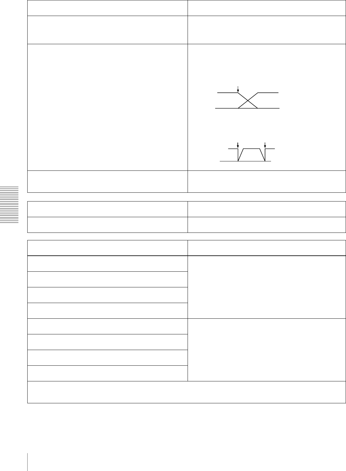
72 Menu Contents
Chapter 4 Menu Settings
SHUTTLE MUTE [>Shutl mute]: Set the audio muting
conditions during shuttle playback.
*OFF [>> OFF]: Not muted.
CUEUP or PREROLL [>> CUEUP]: Muted during cue-up or
preroll operations.
FULL [>> FULL]: Muted in shuttle mode.
AUDIO EDIT [>Audio edit]: Specify the type of editing for
audio signals.
CUT EDIT [>> Cut edit]: Cut editing (Discontinuity in audio
signal may result at the editing point, causing noise during
playback.)
*CROSS FADE [>> Cross]: Cross-fade
FADE IN/OUT [>> Fade]: Fade in and fade out
DV PB ATT [>DV PB ATT]: When playing back a tape
recorded in consumer DV format, select whether to
attenuate the audio output level.
OFF [>> OFF]: Do not attenuate.
*ON [>> ON]: Attenuate.
DIGITAL PROCESS [Digi. proc]: Settings related to digital
process Description of settings
SYSTEM EE MODE [>System EE]: Select the bypass E-E
mode or system E-E mode.
*OFF [>> OFF]: Bypass E-E (ordinary setting)
ON [>> ON]: System E-E
SETUP BANK OPERATION [Setup Bank]: Settings related
to menu bank operations Description of settings
RECALL BANK1 [>Recall 1]: Recall menu settings from
menu bank 1.
(1) Select the bank you want to recall, then press the k
button.
Message “RECALL OK?” appears.
(2) To recall, press the SET (YES) button.
To quit recalling, press the RESET (NO) button.
RECALL BANK2 [>Recall 2]: Recall menu settings from
menu bank 2.
RECALL BANK3 [>Recall 3]: Recall menu settings from
menu bank 3.
RECALL BANK4 [>Recall 4]: Recall menu settings from
menu bank 4.
SAVE BANK 1 [>Save 1]: Save current menu settings to menu
bank 1.
(1) Select the bank you want to save, then press the k
button.
Message “SAVE OK?” appears.
(2) To save, press the SET (YES) button.
To quit saving, press the RESET (NO) button.
SAVE BANK 2 [>Save 2]: Save current menu settings to menu
bank 2.
SAVE BANK 3 [>Save 3]: Save current menu settings to menu
bank 3.
SAVE BANK 4 [>Save 4]: Save current menu settings to menu
bank 4.
Menu banks
This unit allows four different complete sets of menu settings to be saved in what are termed “menu banks” numbered 1 to 4.
Saved sets of menu settings can be recalled for use as required.
AUDIO CONTROL [Audio]: Settings related to audio
control Description of settings
IN/OUT
IN OUT
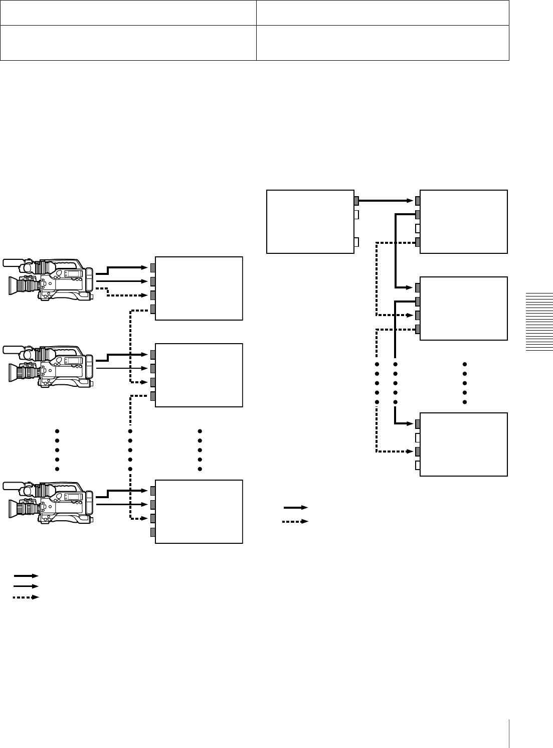
73
Menu Contents
Chapter 4 Menu Settings
EE OUT PHASE settings for time code
output
Use the following as reference information when setting
the EE OUT PHASE menu item (see page 67).
•THROUGH mode
In this mode, the LTC signal is output with the phase
synchronized with the input time code signal. This mode
is appropriate when recording signals from multiple
devices on a number of VCRs.
When the camcorder is in genlock mode, the time code
precision is ±0 frames. When the camcorder is not in
genlock mode, it is ±1 frame.
•VIDEO INPUT PHASE mode
The time code output signal is synchronized with the
input video signal.
This mode is appropriate when the output from a single
device is recorded on a number of VCRs. The
connections are loop-through connections.
In this mode, the same time code is recorded on all of the
VCRs 1 to n.
MENU GRADE [Menu grade]: Selection of menu items to
be displayed Description of settings
Determine whether to display basic items only or both basic
and enhanced items on the monitor screen and in the time
counter display when using the menu.
*BASIC [> Basic]: Display basic items only.
ENHANCED [> Enhanced]: Display both basic and enhanced
items.
VIDEO IN
AUDIO IN
TIME CODE IN
TIME CODE OUT
VIDEO IN
AUDIO IN
TIME CODE IN
TIME CODE OUT
VIDEO IN
AUDIO IN
TIME CODE IN
TIME CODE OUT
Composite video or S-video signal
Audio signal
Time code signal
Camcorder 1
Camcorder 2
Camcorder n
DSR-1800A/1800AP
(1st unit)
DSR-1800A/1800AP
(2nd unit)
DSR-1800A/1800AP
(nth unit)
VIDEO INVIDEO OUT
VIDEO LOOP THRU
TIME CODE IN
TIME CODE OUT
VIDEO IN
VIDEO LOOP THRU
TIME CODE IN
TIME CODE OUT
VIDEO IN
VIDEO LOOP THRU
TIME CODE IN
TIME CODE OUT
Composite video or SDI (video and audio) signal
Time code signal
DSR-1800A/1800AP
(1st unit)
DSR-1800A/1800AP
(2nd unit)
DSR-1800A/1800AP
(nth unit)
Output device
(VCR, camera, etc.)
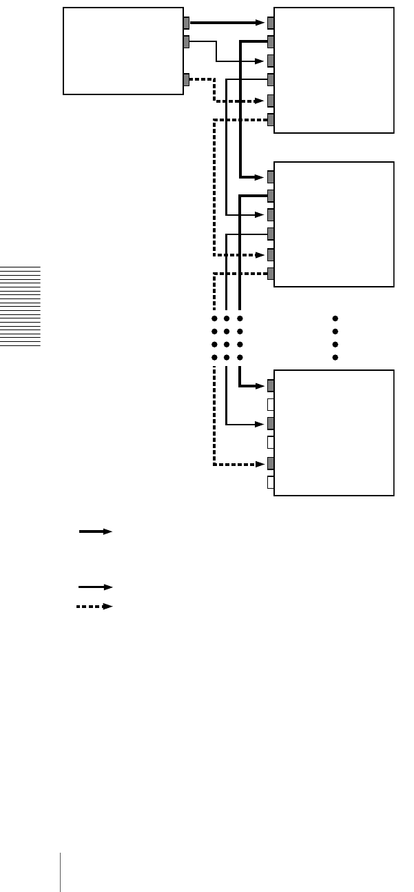
74 Menu Contents
Chapter 4 Menu Settings
•VIDEO OUTPUT PHASE mode
The time code output signal is synchronized with the
output video signal.
This mode is appropriate when outputting signals from a
single device to a number of VCRs using separate cables
for video, audio, and time code.
In this mode, the same time code is recorded on all of the
VCRs 1 to n.
VIDEO INVIDEO OUT
AUDIO OUT
TIME CODE OUT
VIDEO OUT
AUDIO IN
AUDIO OUT
TIME CODE IN
TIME CODE OUT
VIDEO IN
VIDEO OUT
AUDIO IN
AUDIO OUT
TIME CODE IN
TIME CODE OUT
VIDEO IN
VIDEO OUT
AUDIO IN
AUDIO OUT
TIME CODE IN
TIME CODE OUT
• Composite video signal
• S-video signal
• Analog component signal
• SDI (video and audio) signal
Audio signal
Time code signal
Output device
(VCR, camera, etc.)
DSR-1800A/1800AP
(1st unit)
DSR-1800A/1800AP
(2nd unit)
DSR-1800A/1800AP
(nth unit)
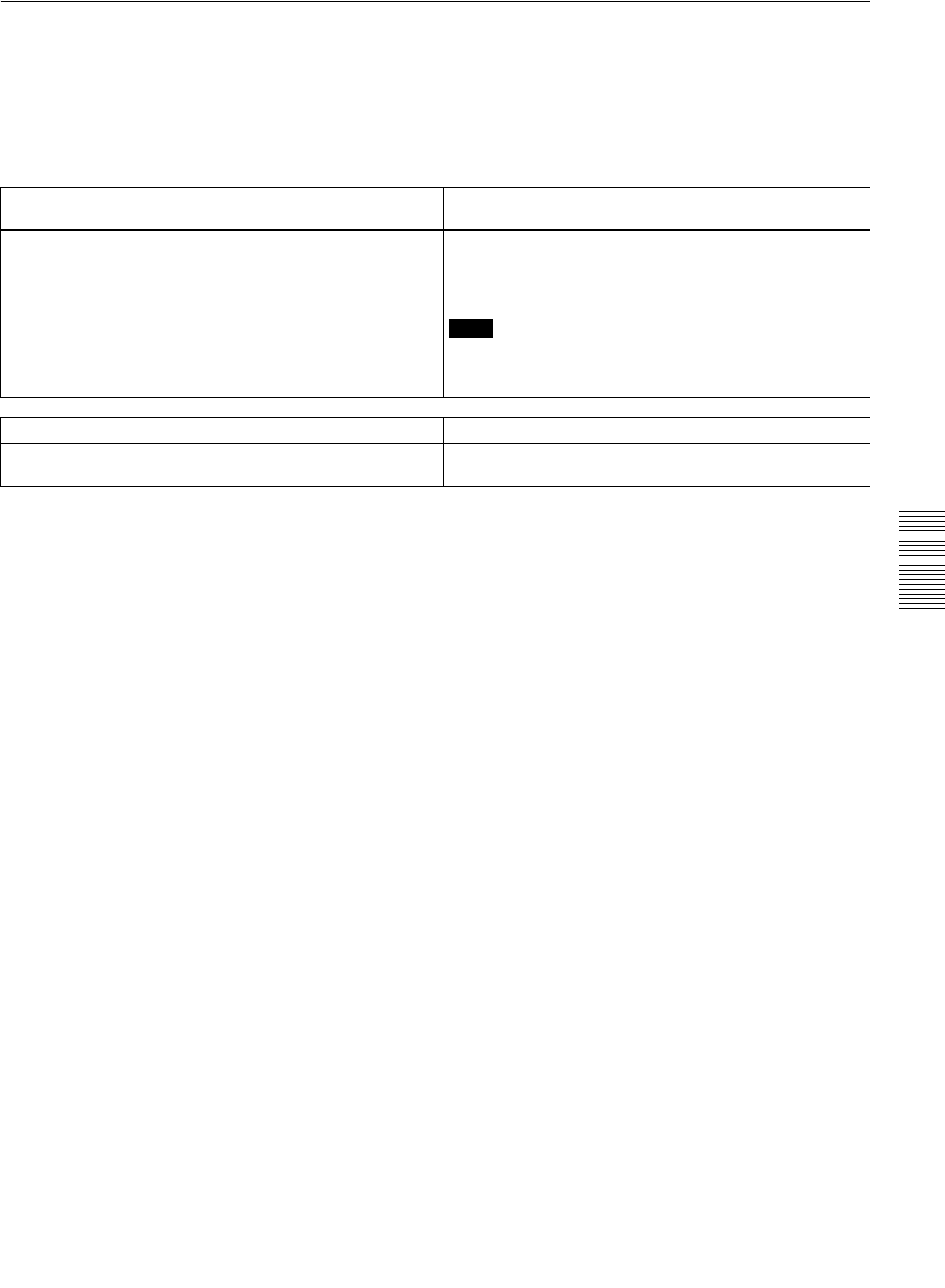
75
Menu Contents
Chapter 4 Menu Settings
Auto Mode (AUTO FUNCTION) Execution Menu
The following table shows the purpose and function of the
items in the auto mode execution menu.
For details of the use of individual items, see “Digitally
Dubbing Signals in DVCAM Format” on page 55 and
“Rerecording the Time Code—TC Insert Function” on
page 51.
Menu contents
i.LINK DUBBING [i.LINK DUB]: Selection of data for i.LINK
dubbing Settings
For dubbing through the i.LINK interface, select data that the
dubbing applies to.
A/V [> A/V]: Dub the audio and video.
A/V/TC [> A/V/TC]: Dub the audio, video, and time code.
A/V/TC/CM [> A/V/TC/CM]: Dub the audio, video, time code,
and cassette memory contents.
Note
When A/V is selected, the time code recorded follows the
setting of the TIME CODE menu items (see page 66) in the
setup menu.
TC INSERT [TC insert]: Time code rewriting Settings
Rewrite the time code from an initial value which can be set
freely.
−
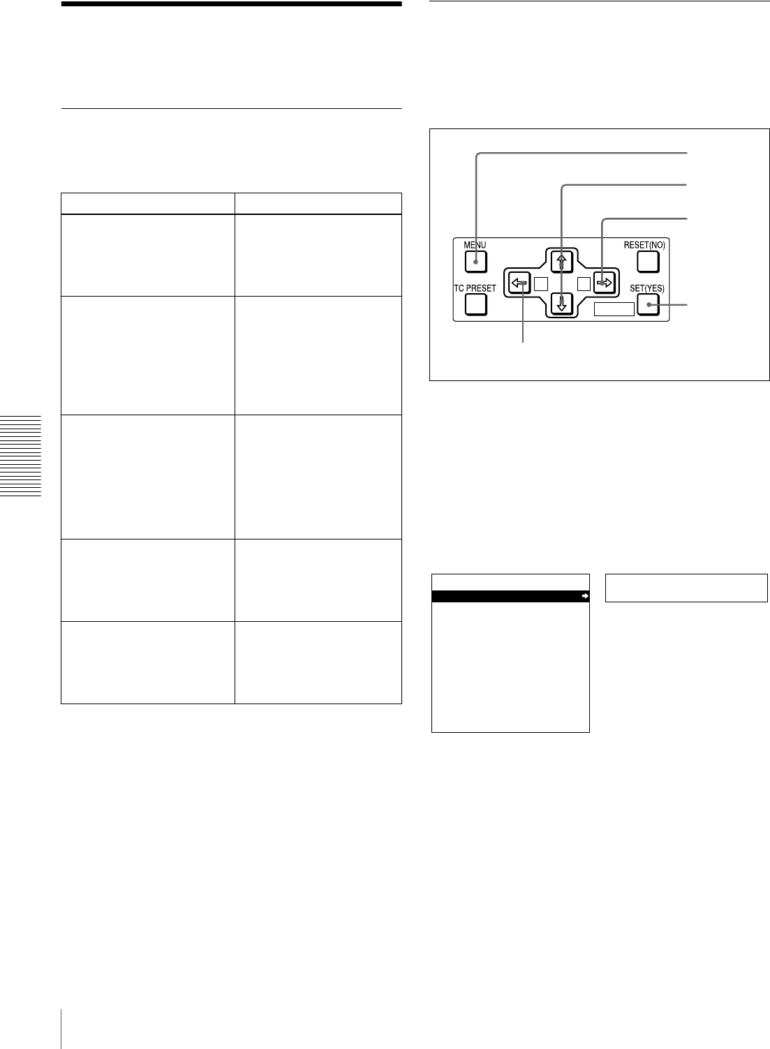
76 Changing Menu Settings
Chapter 4 Menu Settings
Changing Menu Settings
This section explains how to change menu settings.
Buttons Used to Change Settings
Use the following buttons on the menu control panel to
change the menu settings.
Changing the Settings of Basic
Items
The factory default setting is to display only the basic
items. To change the settings of basic items proceed as
follows.
1Press the MENU button on the menu control panel.
The menu selection level display appears on the
monitor. In the figure below, “SETUP MENU” is
selected (shown in reverse video).
The time counter display of this unit shows only the
currently selected item. When the item name is long, it
is abbreviated.
Menu control buttons Functions
MENU button • Opens the menu and
launches menu control
mode.
• Closes the menu and exits
menu control mode.
J and j buttons These buttons move the
highlighted cursor up and
down within the current level
to select an item or setting.
Hold down one of these
buttons to make the
highlighted cursor move
continuously.
K and k buttons • Press the k button to go
down one level.
• Press the K button to go
up one level.
Hold down one of these
buttons to make the
highlighted cursor move
continuously.
RESET (NO) button • Returns the setting to the
factory default setting.
• Sends a negative
response to prompts on
the monitor screen.
SET (YES) button • Saves the new setting in
memory.
• Sends a positive response
to prompts on the monitor
screen.
A B
MARK
8
9
3,5,7
2,4,6
1
Setup menu
SYSTEM MENU
SETUP MENU
AUTO FUNCTION
HOURS METER
Monitor screen
Time counter display
Menu selection level display
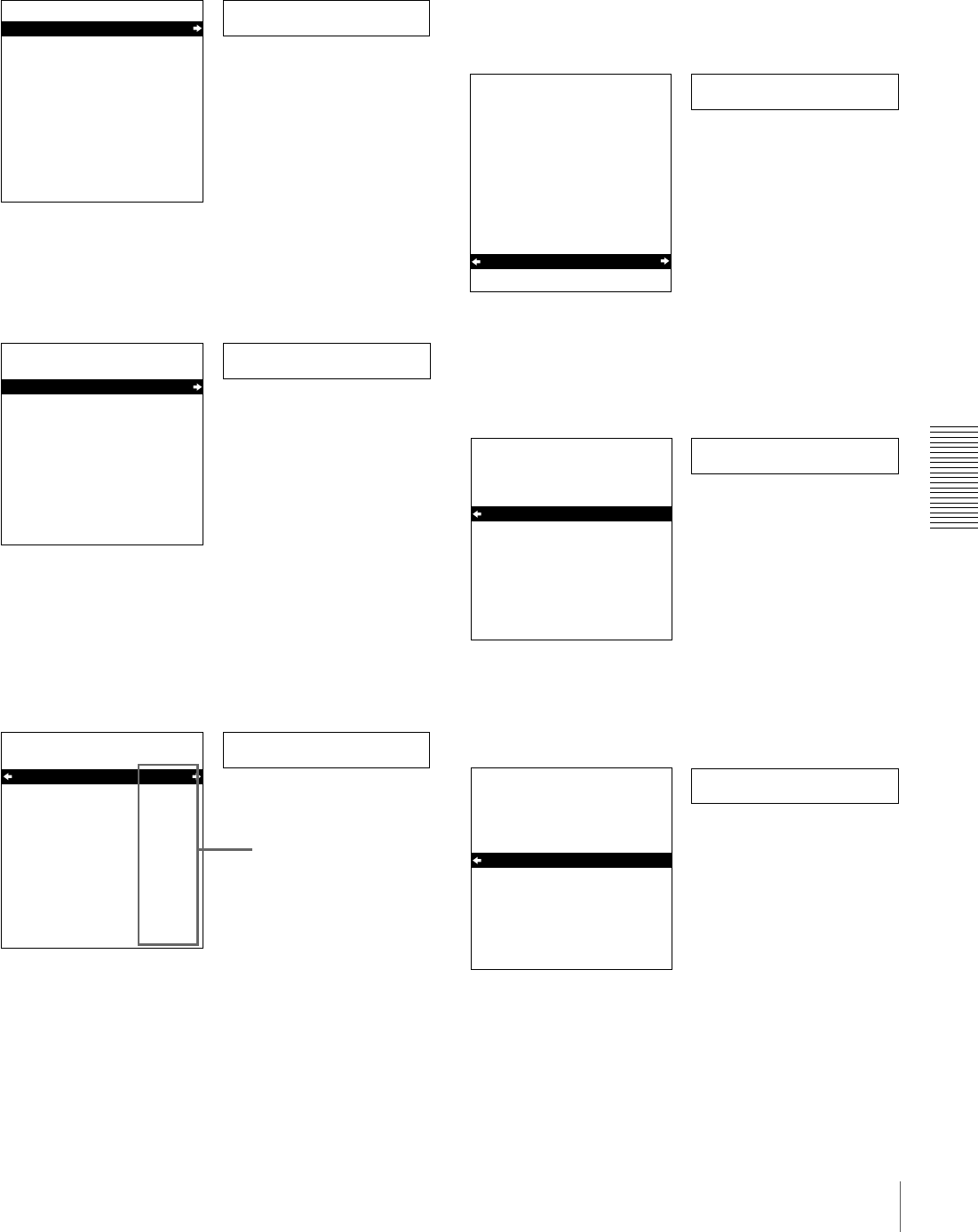
77
Changing Menu Settings
Chapter 4 Menu Settings
2With “SETUP MENU” selected, press the k button.
This displays all items on menu level 1.
3Press the J or j button to select the required item.
4Press the k button.
This displays the menu level 2 for the menu item
selected in step 3.
5Press the J or j button to select the item whose
setting you wish to change.
For menu items on level 3, press the k button to go
to the level 3, then press the J or j button to select the
item whose setting you wish to change.
6Press the k button.
This displays all possible settings for the item selected
in step 5.
7Press the J or j button to change the setting of the
item.
8To change other settings, press the K button to return
to the previous screen, then repeat steps 5 to 7 as
required.
Operational
SETUP MENU
OPERATIONAL FUNCTION
DISPLAY CONTROL
TIME CODE
SETUP BANK OPERATION
MENU GRADE :BASIC
Monitor screen
Time counter display
Level-1 menu display
Display
SETUP MENU
OPERATIONAL FUNCTION
DISPLAY CONTROL
TIME CODE
SETUP BANK OPERATION
MENU GRADE :BASIC
Time counter display
Monitor screen
Example: Display when “DISPLAY CONTROL” is selected
> Chara disp
SETUP MENU
DISPLAY CONTROL
CHARA.DISPLAY
CHARA.POSITION
CHARA.TYPE
CHARA.VSIZE
DISPLAY INFO
SUB STATUS
MENU DISPLAY
PEAK HOLD
OVER DISP HOLD
BRIGHTNESS
ALARM
:ON
:WHITE
:x1
:T&STA
:OFF
:WHITE
:OFF
:OFF
:75%
:ON
Time counter display
Monitor screen
Current settings
Example: Level-2 display for “DISPLAY CONTROL”
> Brightness
SETUP MENU
DISPLAY CONTROL
CHARA.DISPLAY
CHARA.POSITION
CHARA.TYPE
CHARA.VSIZE
DISPLAY INFO
SUB STATUS
MENU DISPLAY
PEAK HOLD
OVER DISP HOLD
BRIGHTNESS
ALARM
:ON
:WHITE
:x1
:T&STA
:OFF
:WHITE
:OFF
:OFF
:75%
:ON
Time counter display
Monitor screen
Example: Display when “BRIGHTNESS” is selected
>> 75%
SETUP MENU
DISPLAY CONTROL
BRIGHTNESS
100%
* 75%
50%
:75% Time counter display
Monitor screen
>> 50%
SETUP MENU
DISPLAY CONTROL
BRIGHTNESS
100%
* 75%
50%
:75% Time counter display
Monitor screen
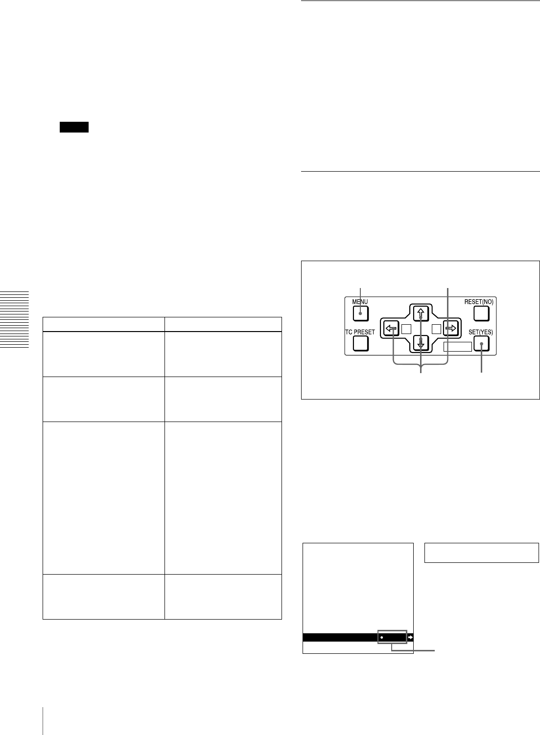
78 Changing Menu Settings
Chapter 4 Menu Settings
9When you have completed the settings, press the SET
(YES) button.
The message “NOW SAVING...” appears on the
monitor screen, and “Saving...” appears in the time
counter display, while the new settings are saved in
memory.
When the saving operation is completed, the monitor
screen and time counter display return to their normal
indications.
Notes
• If you power off the unit before saving operation is
completed, settings may be lost. Wait until the
saving is completed before powering off the unit.
• If, instead of pressing the SET (YES) button, you
press the MENU button, the new settings are not
saved. The message “ABORT!” appears on the
monitor screen and “Abort!” in the time counter
display for about 0.5 second, and the system exits
the menus. To change more than one setting, be sure
to press the SET (YES) button after making the
settings.
Meanings of indications on the monitor
screen
Displaying Enhanced Items
The factory default setting is not to display enhanced
items.
To display enhanced items, set the MENU GRADE menu
item (see page 73) to ENHANCED, following the
procedure in the previous section “Changing the Settings
of Basic Items.” (In step 3, first select “MENU GRADE,”
and next select “ENHANCED,” then press the SET (YES)
button to save the setting in memory.)
With this done, when you press the MENU button and the
k button to display the setup menu, all basic and
enhanced items in the menu level 1 appear.
Changing the Settings of Enhanced
Items
To change the settings of enhanced items, first carry out
the procedure in the previous section “Displaying
Enhanced Items,” then proceed as follows.
1Press the MENU button on the menu control panel.
The menu selection level display appears on the
monitor.
2With “SETUP MENU” selected, press the k button.
This displays all basic and enhanced items on menu
level 1.
On-screen indication Meaning
Right-pointing arrow (k) at
the right of a menu item
See step 1 of the foregoing
operating procedure.
Pressing the k button
switches to the next lower
menu level or to a setting
selection screen.
Left-pointing arrow (K) at
the left of a menu item
See step 4 of the foregoing
operating procedure.
Pressing the K button
returns to the previous
(higher) menu level.
Character string at the right of
a menu item
See step 4 of the foregoing
operating procedure.
Current setting of the menu
item.
• When shown with a colon
(:): the current setting is
the same as the factory
default setting.
• When shown with a raised
dot (•): the current setting
is different from the factory
default setting.
See step 2 of the operating
procedure in “Changing the
Settings of Enhanced Items”
on page 78.
An asterisk in a complete list
of settings
See step 6 of the foregoing
operating procedure.
Factory default setting.
A B
MARK
2
1
34
Menu grade
SETUP MENU
OPERATIONAL FUNCTION
DISPLAY CONTROL
TIME CODE
TAPE PROTECTION
VIDEO CONTROL
AUDIO CONTROL
DIGITAL PROCESS
SETUP BANK OPERATION
MENU GRADE ENHAN
Time counter display
Monitor screen
Current setting
Level-1 menu display

79
Changing Menu Settings
Chapter 4 Menu Settings
3Follow the same procedure as in steps 3 to 8 of the
procedure in the section “Changing the Settings of
Basic Items” on page 76 using the arrow buttons to
select an item and change its setting.
4When you have completed the settings, press the SET
(YES) button.
The message “NOW SAVING...” appears on the
monitor screen, and “Saving...” appears in the time
counter display, while the new settings are saved in
memory.
When the saving operation is completed, the monitor
screen and time counter display return to their normal
indications.
Returning Menu Settings to Their
Factory Default Settings
After making menu setting changes, to return settings to
their factory default settings (setting initialization), use the
following procedure.
To return a particular setting to its factory
default setting
In the display for changing the target setting, press the
RESET (NO) button.
Carry out the procedure in the section “Changing the
Settings of Basic Items” on page 76 up to step 6, then with
the current setting displayed (in the example, if the setting
has been changed it will be “100%” or “50%”), press the
RESET (NO) button. The setting returns to its factory
default setting of “75%.”
To return all settings to their factory
default settings
Use the following procedure.
1Press the MENU button on the menu control panel to
display the menu selection.
2Press the k button to display level 1 of the setup
menu.
3Press the RESET (NO) button.
A message appears, to confirm whether or not you
wish to return all settings to their factory default
settings.
4Press the SET (YES) button.
The message “NOW SAVING...” appears on the
monitor screen, and “Saving...” appears in the time
counter display, while the settings of all items are
returned to their factory default settings. These factory
default settings are saved in memory.
Note
If you power off the unit while settings are being
saved, settings may not be correctly returned to their
factory default settings. Wait until the saving is
completed before powering off the unit.
To abandon the resetting operation
Instead of pressing the SET (YES) button, press the
RESET (NO) button. The display returns to menu
level 1, leaving the settings unchanged.
Monitor screen
message “INITIALIZE ALL ITEMS TO
FACTORY PRESET VALUES?”
Message in the time
counter display “Init setup?”
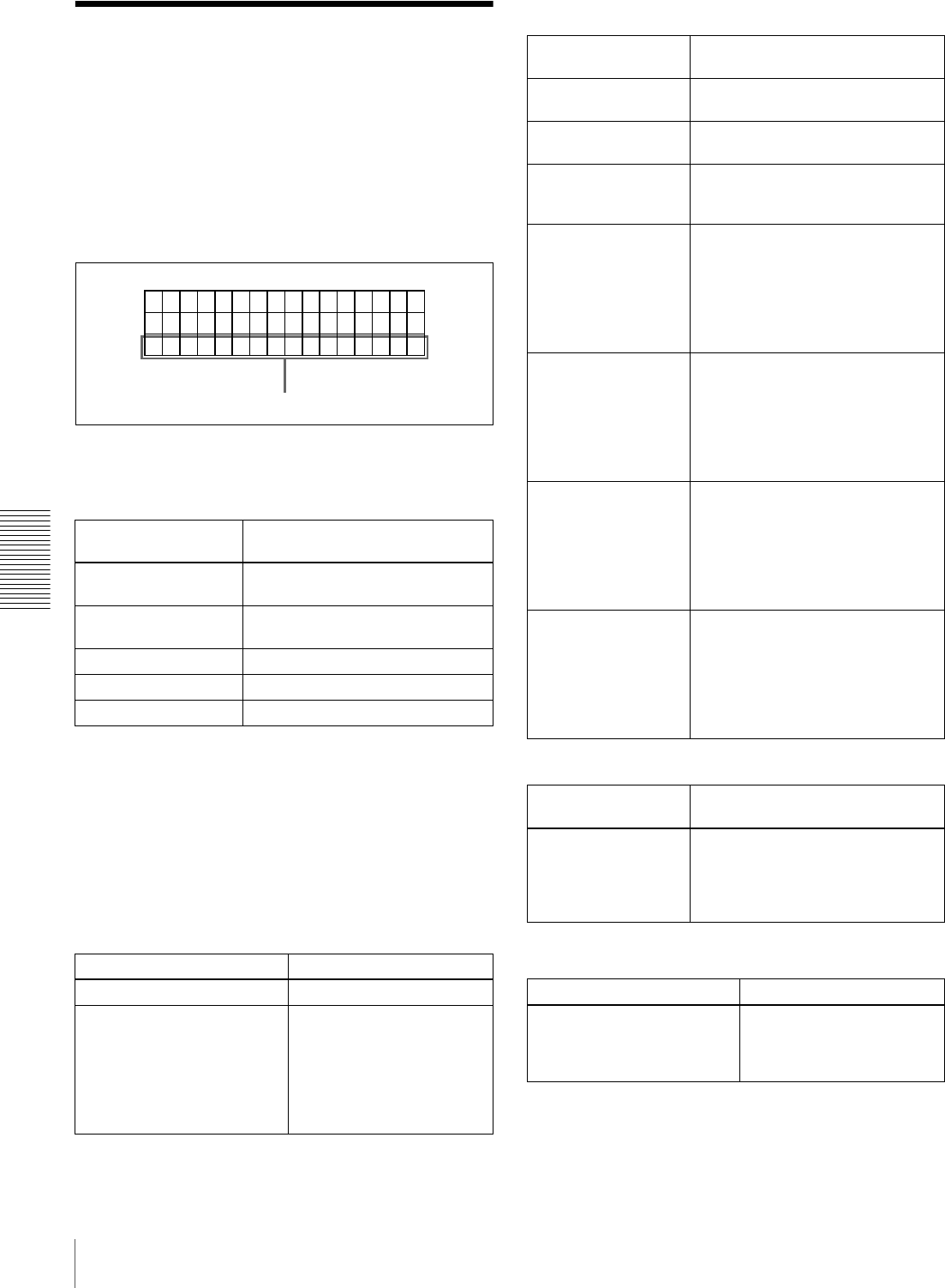
80 Displaying Supplementary Status Information
Chapter 4 Menu Settings
Displaying
Supplementary Status
Information
When you set the SUB STATUS menu item (see page 65)
to other than OFF, you can view supplementary status
information on the monitor screen below the operating
mode display area.
The following items of supplementary status information
are displayed depending on the setting of the SUB
STATUS menu item.
The following tables show the on-screen indications of
supplementary information and their meaning.
In each table, the indications given in brackets such as
[ASM] are the indications displayed when the SUB
STATUS menu item is set to ALL.
For the display format when ALL is selected, see page 81.
Setting of SUB
STATUS menu item Items of supplementary
information displayed
EDIT PRESET Editing mode settings made on the
editing control unit
TC MODE Operating mode of the internal time
code generator
REMAIN Remaining capacity of the tape
AUDIO MIXING Setting for input audio mixing
ALL All of the above items
When the SUB STATUS menu item is set to EDIT
PRESET:
On-screen indication Meaning
ASM [ASM] Assemble editing mode
INS V A1234 TC
[V1234T]
INS: Insert editing mode
V A1234 TC: Channels or
signals selected for
insert editing
V: Video
A1234: Audio 1, 2, 3, 4
TC: Time code
TCR
PLAY
00:04 47
.07
LOCK
.
IN V A1 34
2TCS
Supplementary status information
When the SUB STATUS menu item is set to TC MODE:
On-screen
indication Meaning
INT PRESET FREE
[IP F]
The internal time code generator is
operating in FREE RUN mode.
INT PRESET REC
[IP R]
The internal time code generator is
operating in REC RUN mode.
INT REGEN-T&U
[IRTU]
The internal time code generator is
in synchronization with the playback
time code (LTC) read from tape.
EXT LTC-T&U
[ELTU]
The internal time code generator is
in synchronization with the external
time code (LTC) input to the unit
and is generating the same time
code value and user bit value as
those of the external time code
(regeneration).
EXT VITC-T&U
[EVTU]
The internal time code generator is
in synchronization with VITC
present in the external video signal
input to the unit and is generating
the same time code value and user
bit value as those of the external
time code (regeneration).
EXT DVIN-T&U
[EDTU]
The internal time code generator is
in synchronization with the external
time code input to the unit via i.LINK
(DV IN) interface and is generating
the same time code value and user
bit value as those of the external
time code (regeneration).
EXT DVIN.V-T&U
[EDTU]
The internal time code generator is
in synchronization with the external
VITC input to the unit via i.LINK (DV
IN) interface and is generating the
same time code value and user bit
value as those of the external time
code (regeneration).
When the SUB STATUS menu item is set to REMAIN:
On-screen
indication Meaning
REMAIN 184 min Remaining capacity of the tape in
minutes.
When the remaining capacity has
not been detected, “REMAIN ---
min” appears.
When the SUB STATUS menu item is set to AUDIO
MIXING:
On-screen indication Meaning
1234
[MIX]
Input audio channels
selected for mixing
1234: Input audio channels
1, 2, 3 and 4
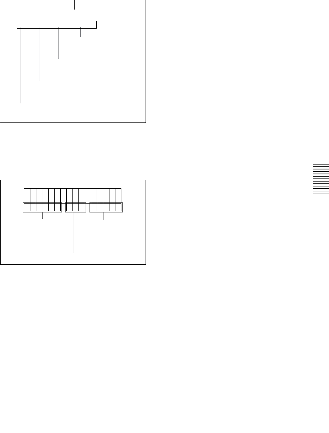
81
Displaying Supplementary Status Information
Chapter 4 Menu Settings
Display format of supplementary status
information when the SUB STATUS menu item is
set to ALL
All items of supplementary status information are
displayed in the order shown below.
When the SUB STATUS menu item is set to AUDIO
MIXING:
On-screen indication Meaning
122334
Input audio channels 3 and
4 are mixed and recorded
on audio channel 4 on tape.
Input audio channel 3 is recorded
on audio channel 3 on tape.
Input audio channel 2 is recorded
on audio channel 2 on tape.
Input audio channels 1 and 2 are mixed and
recorded on audio channel 1 on tape.
Example display:
TCR
PLAY
00:04 47
:07
LOCK
.
VV12 4T MI E
XTU
D
3
Setting for input audio mixing
Operating mode of the internal
time code generator
(The rightmost “V” appears
when the VITC menu items
(see page 67) is set to ON.)
Editing mode settings

82 Displaying Supplementary Status Information
Chapter 4 Menu Settings
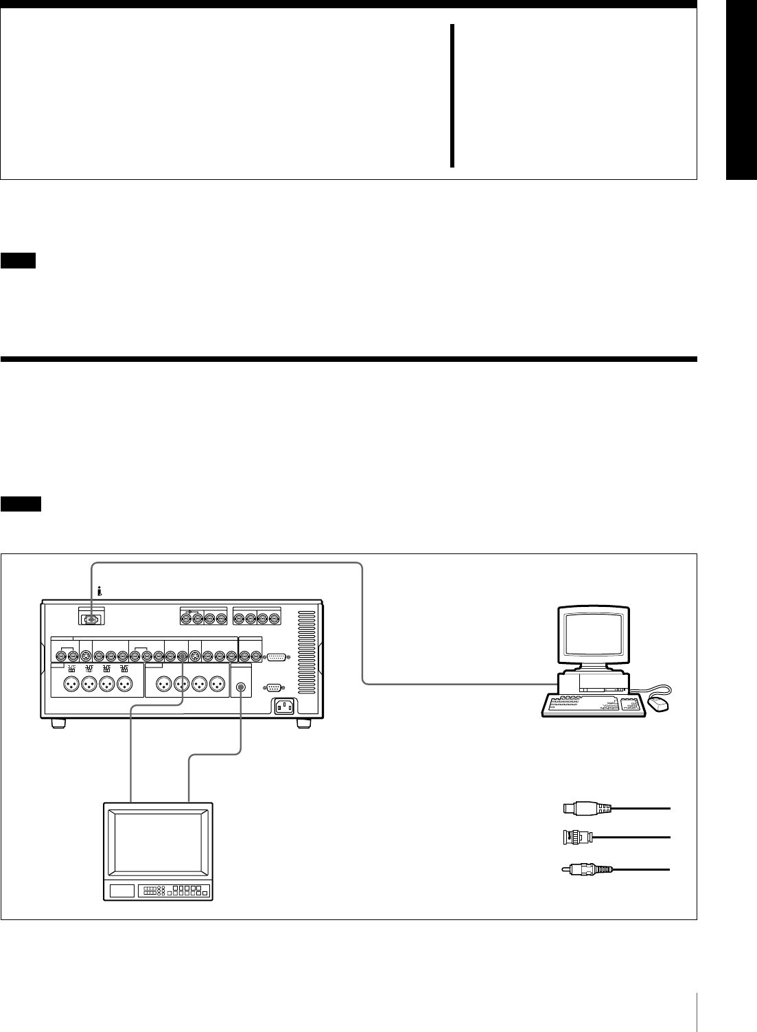
83
Connections for a Digital Non-Linear Editing System
Chapter 5
Connections and
Settings
Note
Production of some of the peripherals and related devices
described in this chapter has been discontinued. For advice
about choosing devices, please contact your Sony dealer or
a Sony sales representative.
Connections for a Digital Non-Linear Editing System
This unit can be connected to a nonlinear editor supporting
DV/DVCAM with an i.LINK cable (DV cable). Shown
below is an example of connections to use this unit as a
recorder in a nonlinear editing system.
Notes
• Refer to the documentation of your nonlinear editing
equipment and software for more information about
connection and settings on the nonlinear editing
equipment.
• Different editing software applications provide different
editing functions. For more information about actual
editing procedures and settings, refer to the
documentation of your editing software.
DV IN/OUT
AUDIO
MONITOR OUT
VIDEO OUT 2
(SUPER)
1
23
DSR-1800A/
1800AP (recorder)
Nonlinear editing system
Audio input
Composite
video input
B75 Ω coaxial cable (not supplied)
CCable with RCA phono plugs
(not supplied)
Video monitor
Ai.LINK cable (DV cable)
(not supplied)

84 Connections for a Digital Non-Linear Editing System
Chapter 5 Connections and Settings
Settings on the DSR-1800A/1800AP
For details of video/audio input and audio mode settings,
see “Settings for Recording” on page 31.
Notes
• When you connect this unit to another device with a 6-
pin DV connector, always power the other device off and
unplug its power cord from the power output before
connecting or disconnecting the i.LINK cable (DV
cable). If you connect or disconnect the cable with the
power cord still plugged in, power from the DV
connector may flow into this unit, possibly damaging
this unit.
• When you connect this unit to another device with a 6-
pin DV connector, make the connection to the 6-pin DV
connector on the other device before making the
connection to this unit.
Button Setting
REMOTE On (lit)
9PIN Off (Unlit)
i.LINK On (lit)
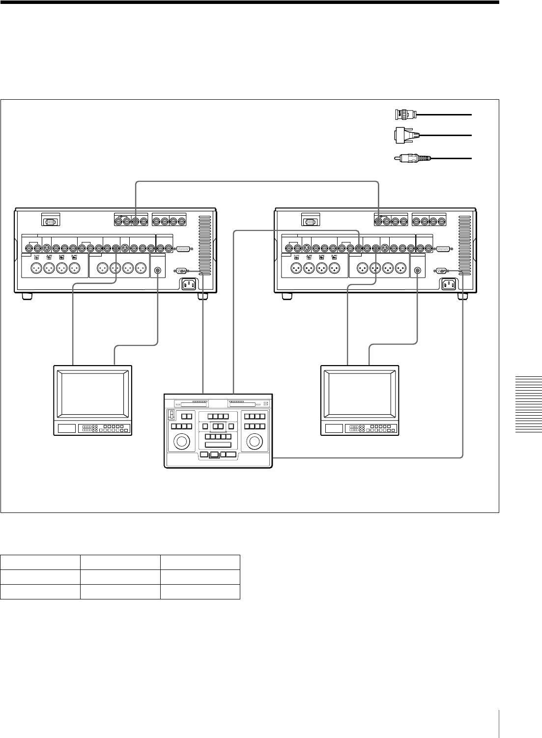
85
Connections for a Cut Editing System
Chapter 5 Connections and Settings
Connections for a Cut Editing System
The following figure shows a cut editing system
configuration that includes two DSR-1800A/1800AP units
to serve as the player and recorder.
When using a VCR other than the DSR-1800A/1800AP,
refer to its instruction manual.
Settings on the DSR-1800A/1800APs (recorder
and player)
For details of the video/audio input and audio mode
settings for the recorder, see “Settings for Recording” on
page 31.
About reference video signals
In order to provide stable video and audio signals for
analog editing, it is necessary for the built-in time base
corrector (TBC) to operate correctly. To ensure this, input
a reference video signal synchronized with the video signal
to the REF. VIDEO IN connector.
RECORDER
SDI OUT
AUDIO
MONITOR
OUT
AUDIO
MONITOR
OUT
VIDEO
OUT 2
(SUPER)
REMOTE
SDI IN
VIDEO
OUT 2
(SUPER)
REMOTE
REF.
VIDEO
OUT
REF.
VIDEO IN
PLAYER
1
1321 132
When you select assemble or insert editing mode on
the editing control unit, the two DSR-1800A/1800AP
units (recorder and player) will automatically enter the
selected editing mode.
A75 Ω coaxial cable (not supplied)
CCable with RCA phono plugs
(not supplied)
B9-pin remote control cable
(not supplied)
DSR-1800A/
1800AP (player) DSR-1800A/
1800AP (recorder)
Audio input
Composite
video input
Source monitor Main monitor
Editing control unit (PVE-500, etc.) a)
Audio input
a) For the settings on the editing control unit, see
“Settings on an editing control unit” on page
90.
Composite
video input
DSR-1800A/
1800AP (player)
Button Recorder Player
REMOTE On (lit) On (lit)
9PIN On (lit) On (lit)
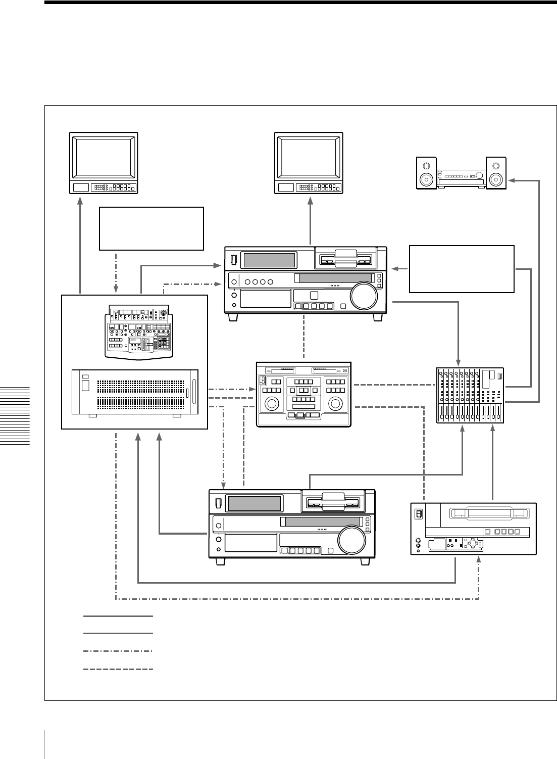
86 Connections for an A/B Roll Editing System
Chapter 5 Connections and Settings
Connections for an A/B Roll Editing System
The following is an example configuration of A/B roll
editing system using the DSR-1800A/1800AP.
The purpose of the following figure is to clearly indicate
the flow of signals among the component devices in this
system. The specific connections and settings are
described beginning on page 87.
a) An I/O delay of several frames occurs on DME switchers and
other devices equipped with frame memory. It is therefore
necessary to connect an audio delay unit between the audio
mixer and the recorder VCR to adjust for the delay.
Main video monitor Source video monitor
Video signal generator DSR-1800A/
1800AP (recorder)
Audio mixer
(MXP-290, etc.)
Editing control unit
(PVE-500, etc.)
Control signal
DME switcher
(DFS-500/500P,
etc.)
DSR-1600A/1600AP (player 1) UVW-1600/1600P,
etc.
(player 2)
Video signal
Audio signal
Reference video signal
DPS-D7 or other delay
unit a)
Audio system monitor
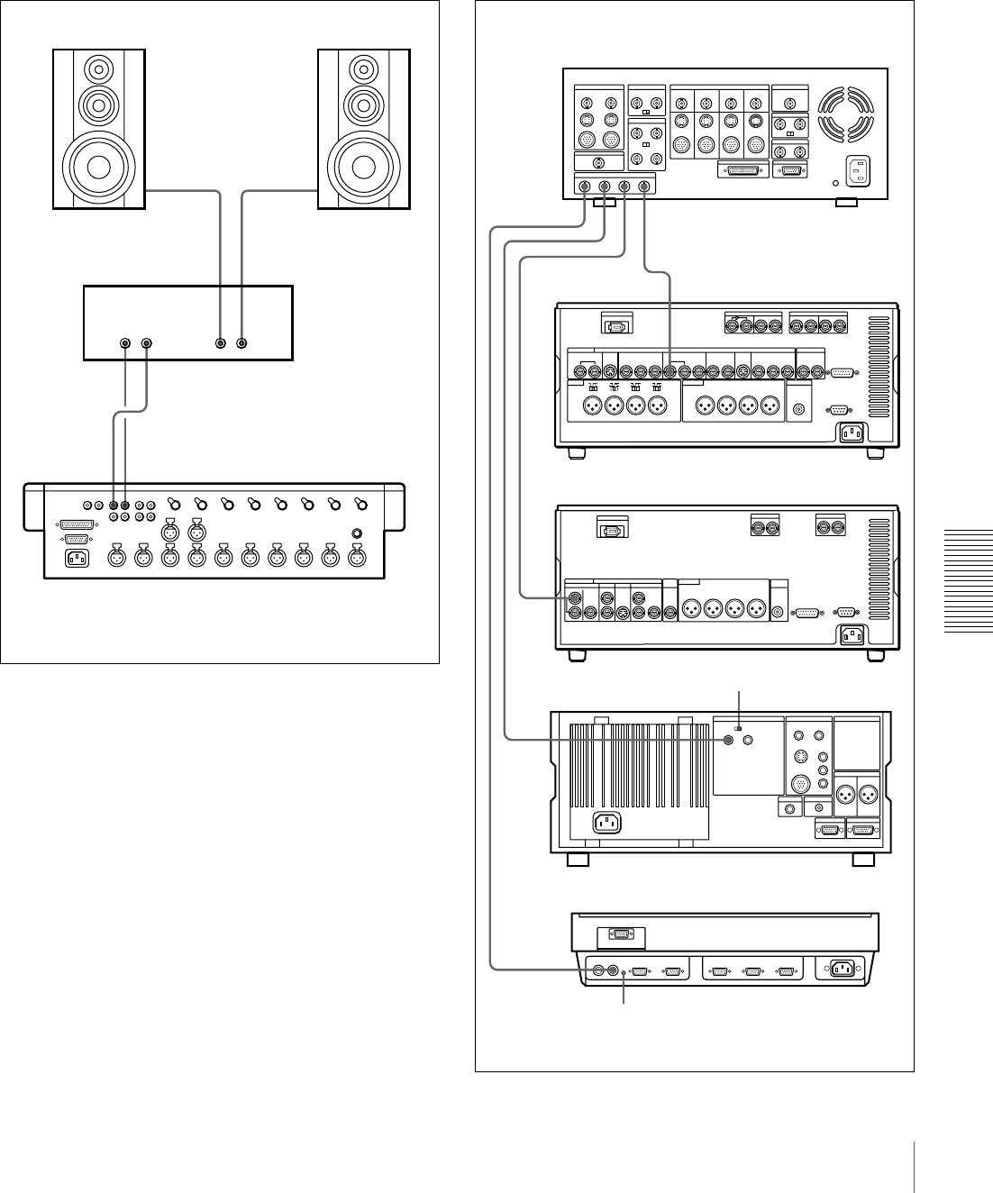
87
Connections for an A/B Roll Editing System
Chapter 5 Connections and Settings
Audio monitor system connections
The following shows an example of audio monitor system
connections.
For details of these connections, refer to the instruction
manual for each connected device.
Reference video signal connection
When you perform recording, be sure to input a reference
video signal.
For details of reference video signals, see “About
reference video signals” on page 85.
LRLR
MONITOR
OUT 1
MONITOR
OUT 2
Speaker (left channel)
Audio amplifier
Audio mixer (MXP-290, etc.)
Cables with RCA phono plugs
Speaker (right channel)
REF. VIDEO IN
REF.
VIDEO
IN
REF. VIDEO IN
REF. VIDEO IN
1234
BLACK
BURST
OUT
DME switcher
(DFS-500/500P, etc.)
DSR-1800A/
1800AP (recorder)
UVW-1600/1600P, etc.
(player 2)
Editing control unit
(PVE-500, etc.)
Use 75 Ω coaxial cables for all of these connections.
DSR-1600A/
1600AP (player 1)
REF. VIDEO IN 75 Ω termination switch: ON
REF. VIDEO IN 75 Ω
termination switch: ON
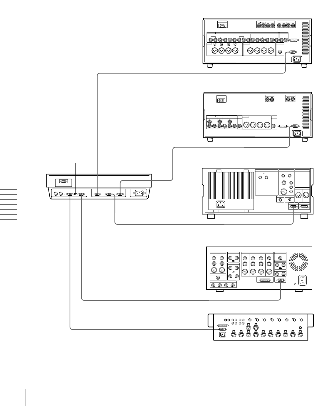
88 Connections for an A/B Roll Editing System
Chapter 5 Connections and Settings
Control signal connections
The following shows an example of control signal
connections to enable the editing control unit to control all
other A/B roll editing system devices.
SWITCHER PLAYER 2MIXER
PLAYER 1
RECORDER
REMOTE
REMOTE
REMOTE
EDITOR
DSR-1800A/1800AP (recorder)
9-pin remote control cable (not supplied)
DSR-1600A/1600AP (player 1)
Mixer control mode
selection switch:
PARALLEL
9-pin remote control cable (not supplied)
UVW-1600/1600P, etc. (player 2)
Editing control unit
(PVE-500, etc.)
DME switcher
(DFS-500/500P, etc.)
9-pin remote control cable (not supplied)
9-pin/15-pin mixer control cable (not supplied)
EDITOR (15-pin)
Audio mixer
(MXP-290, etc.)
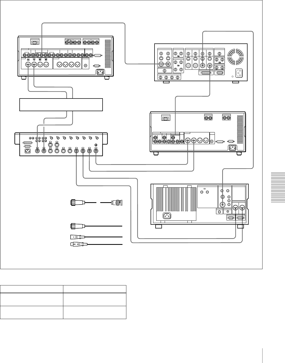
89
Connections for an A/B Roll Editing System
Chapter 5 Connections and Settings
Video/audio signal connections
The following shows an example of video/audio signal
connections in an A/B roll editing system.
In this example, analog component signals are used as the
video signals and XLR 3-pin connectors are used as audio
input/output connectors.
Settings on the DSR-1800A/1800AP (recorder) For details of the video/audio input and audio mode
settings, see “Settings for Recording” on page 31.
VIDEO INPUTS
COMPONENT 2
VIDEO INPUTS
COMPONENT 1
COMPONENT VIDEO OUT
Y, R–Y, B–Y
COMPONENT VIDEO IN
Y, R–Y, B–Y
PGM OUT
COMPONENT 1
AUDIO IN
CH-1
CH-2
LINE OUT 2 LINE OUT 1
1234MIC/LINE
IN
AUDIO OUT
CH-1 CH-2
COMPONENT 1
OUTPUT
AUDIO OUTPUT
CH-1 CH-2
CH-2 OUTCH-1 OUT
CH-2 INCH-1 IN
1
1
2
3
3
3
3
3
3
3
3
DME switcher
(DFS-500/500P, etc.)
CCable with XLR
connectors (not supplied)
Audio mixer
(MXP-290, etc.)
DSR-1800A/
1800AP (recorder)
UVW-1600/1600P, etc.
(player 2)
A12-pin/3-BNC cross cable
(not supplied; consult your
Sony dealer about this cable.)
DSR-1600A/
1600AP (player 1)
DPS-D7 or other delay unit
B12-pin dubbing cable
(not supplied)
Switch/menu Setting
AUDIO IN LEVEL/600 Ω
switches
HIGH-ON
LEVEL SELECT menu item Normally +4 dBm (see page
71)
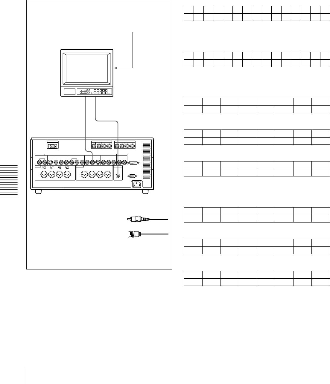
90 Connections for an A/B Roll Editing System
Chapter 5 Connections and Settings
Connection of a video monitor
Set up the following connections to enable monitoring of
video and audio signals on a video monitor. In addition to
the video and audio signals, you can have time data, the
operation mode of the unit, alarm messages, and other
information displayed as text on the monitor screen by
setting the CHARA. DISPLAY menu item (see page 65)
to ON (factory default setting).
Settings on an editing control unit
When connecting an editing control unit, make the settings
as follows, according to the model.
PVE-500
No settings are required.
BVE-600/900/910/2000 (NTSC model) or FXE-100/
120
Set the VCR constants as follows.
BVE-600/900/910/2000 (PAL model) or FXE-100P/
120P
Set the VCR constants as follows.
RM-450/RM-450CE
Set the DIP switches as follows.
• Left switches
• Right switches (RM-450)
)
• Right switches (RM-450CE)
BVE-800
Set the DIP switches as follows.
•SW2
•SW3 (NTSC model)
•SW3 (PAL model)
VIDEO
OUT
2(SUPER)
AUDIO
MONITOR OUT
21
75 Ω termination switch: ON (or attach a 75
Ω terminator)
Input switches: Set according to the type of
input signals.
Video monitor
Audio input
Composite
video input
ACable with RCA phono plugs
(not supplied)
B75 Ω coaxial cable
(not supplied)
DSR-1800A/1800AP (recorder)
123456789101112131415
80 15 00 96 05 05 03 80 0A 08 FE 00 80 5A FF
123456789101112131415
81 15 00 7D 05 05 02 80 0A 07 FE 00 80 4C FF
76543210
OFF −−OFF −−−−
76543210
OFF −OFF ON OFF OFF ON ON
76543210
ON −OFF ON OFF OFF ON ON
12345678
ON OFF ON ON −ON ON −
12345678
ON ON ON OFF −ON OFF OFF
12345678
OFF OFF OFF ON −ON OFF OFF
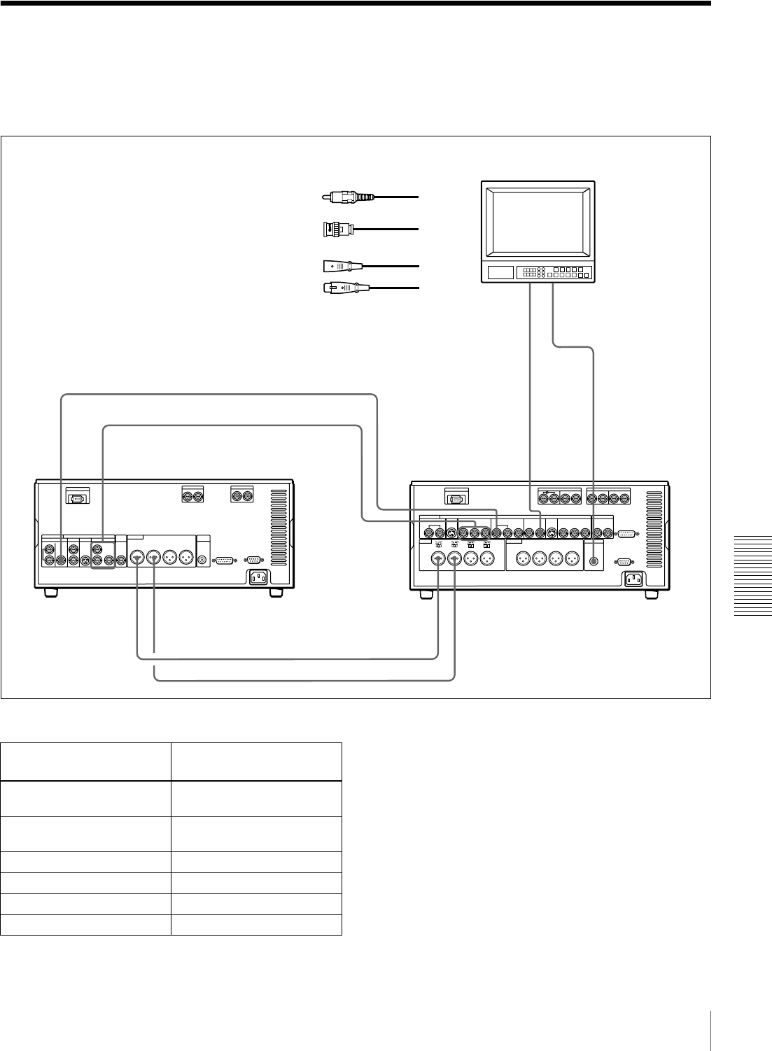
91
Connections for Analog Recording
Chapter 5 Connections and Settings
Connections for Analog Recording
The following shows connections for a system in which
analog playback signals from another recorder or player
are recorded on a DSR-1800A/1800AP. In this system, the
video signals are analog component signals and the audio
signals are recorded from audio channels 1 and 2.
Settings on the DSR-1800A/1800AP (recorder)
a) For details of the video/audio input and audio mode settings, see “Settings
for Recording” on page 31.
VIDEO
OUT
2(SUPER)
REF.VIDEO
IN
AUDIO
MONITOR OUT
COMPONENT VIDEO OUT
Y,R–Y,B–Y
COMPONENT
VIDEO IN
Y,R–Y,B–Y
a)
REF.
VIDEO
OUT
AUDIO OUT
CH-1 CH-2 AUDIO IN
CH-1 CH-2
2
2
3
3
21
Video monitor
Composite
video input
Audio input
DSR-1600A/1600AP (player) DSR-1800A/1800AP (recorder)
B75 Ω coaxial cable
(not supplied)
CCable with XLR connectors
(not supplied)
ACable with RCA phono plugs
(not supplied)
a) Three 75 Ω coaxial cables are used,
one each for Y, R−Y, and B−Y.
Switch/menu/input/audio
mode a)
Setting
AUDIO IN LEVEL/600 Ω
switches
HIGH-ON
LEVEL SELECT menu item Normally +4 dBm (see page
71)
REMOTE button Off (unlit)
Video input Component
Audio input Analog
Audio mode 2 channel/48 kHz
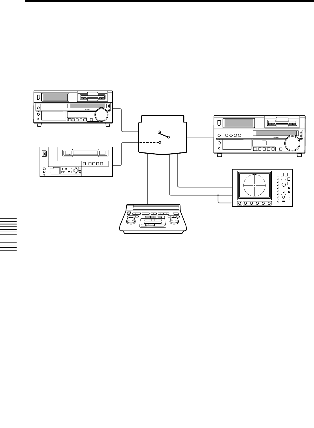
92 Adjusting the Sync and Subcarrier Phases
Chapter 5 Connections and Settings
Adjusting the Sync and Subcarrier Phases
When using two or more players, as in an A/B roll editing
system, it is necessary to synchronize the sync and
subcarrier (for composite signals) phases of the signals to
be edited. If they are not synchronized, picture instabilities
or color break-up may occur at edit points.
After configuring the editing system, use a vectorscope to
adjust the sync and subcarrier phases of the recorder and
players. Subcarrier phase adjustment is necessary when
using composite signals and Y/C signals.
b) Ensure that the 75 Ω coaxial cables (A) and
(B) (not supplied) are of the same length.
DSR-1600A/1600AP (player 1)
UVW-1600/1600P, etc. (player 2)
Switcher (DFS-500/500P, etc.) a)
75 Ω coaxial cable (B) b)
Editing control unit
(PVE-500, etc.)
a) The sync and subcarrier phases of the
output signal from the DFS-500/500P
switcher are automatically adjusted.
Vectorscope
75 Ω coaxial cable (A) b)
DSR-1800A/1800AP (recorder)
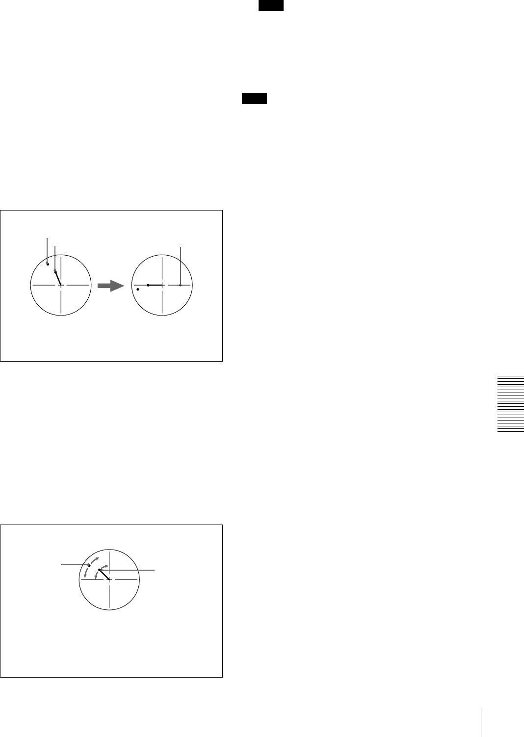
93
Adjusting the Sync and Subcarrier Phases
Chapter 5 Connections and Settings
Performing a phase adjustment operation
1Press the SCH button on the vectorscope.
The vectorscope switches to SCH mode.
2Press the B channel button on the vectorscope.
This displays the black burst signal from the switcher.
3Press the EXT button on the vectorscope.
This switches the vectorscope to external
synchronization mode.
4Adjust the phase synchronization control on the
vectorscope so that the sync and subcarrier phases are
close to the reference line.
5Output the player 1 signal.
6Press the A channel button on the vectorscope.
This displays the sync and subcarrier phases
(composite signals only) of the signal from player 1.
7On player 1, adjust the SYNC PHASE and SC PHASE
controls on the menu control panel, using a Phillips
screwdriver, so that the output from player 1 on
channel A is in correct phase alignment with the black
burst signal on channel B.
Note
When component signals are used the subcarrier phase
indicator does not appear.
8Output the player 2 signal and repeat steps 6 and 7 to
adjust the sync and subcarrier phases of the output
from player 2.
Note
Note
The color of video on monitors connected to the composite
and S-video outputs may temporarily change or be
reversed when you rotate the SYNC PHASE control and
SC PHASE control.
Align the sync and subcarrier phases of the black
burst signal to the reference line.
Sync phase
Reference line
Subcarrier phase
Adjust the sync and subcarrier phases of the output
signal from player 1.
This indicator
moves as you
turn the SYNC
PHASE control.
This indicator
moves as you
turn the SC
PHASE control.

94 Adjusting the Sync and Subcarrier Phases
Chapter 5 Connections and Settings

95
Maintenance
Chapter 6
Maintenance and
Troubleshooting
Maintenance
Condensation
If you move the unit suddenly from a cold to a warm
location, or if you use it in a very humid place, moisture
from the air may condense on the head drum. This is called
condensation, and if a tape is run in this state, the tape may
stick to the drum and can be easily damaged. To lessen the
risk of this occurring, this unit is equipped with a
condensation detection system.
If condensation occurs while the unit is
operating:
The alarm message “MOISTURE HAS BEEN
DETECTED.” appears on the monitor screen, and the
alarm message “HUMID!” in the time counter display. At
the same time the unit ejects the cassette automatically. If
this happens, leave the unit powered on and wait until the
alarm messages disappear.
If the condensation alarm message appears
immediately after powering on:
Leave the unit powered on and wait until the alarm
message disappears. You cannot load a cassette into the
unit while the alarm message is being displayed.
Once the alarm message disappears, the unit is ready for
use.
Regular Checks
Digital hours meter
The digital hours meter keeps cumulative counts of the
total operating time, the head drum rotation time, the tape
transport operating time, and the number of threading/
unthreading operations. These counts can be displayed on
the monitor screen and in the time counter display of this
unit. Use them as guidelines for scheduling maintenance.
In general, consult your Sony dealer about necessary
periodic maintenance checks.
Digital hours meter display modes
The digital hours meter has the following four display
modes.
•T1 (OPERATION) mode
The cumulative total hours during which the unit is
powered on is displayed in 10-hour increments.
•T2 (DRUM ROTATION) mode
The cumulative total hours of drum rotation with tape
threaded is displayed in 10-hour increments.
•T3 (TAPE RUNNING) mode
The cumulative total hours of tape transport operation
for fast forward, rewind, playback, and search (except in
still search mode) is displayed in 10-hour increments.
•CT (THREADING) mode
The cumulative number of tape threading/unthreading
operation pairs is displayed in 10-operation pair
increments.
For all modes except T1 (OPERATION), there are two
types of count: a “trip” count, which is resettable, and the
cumulative total from manufacture, which is unresettable.
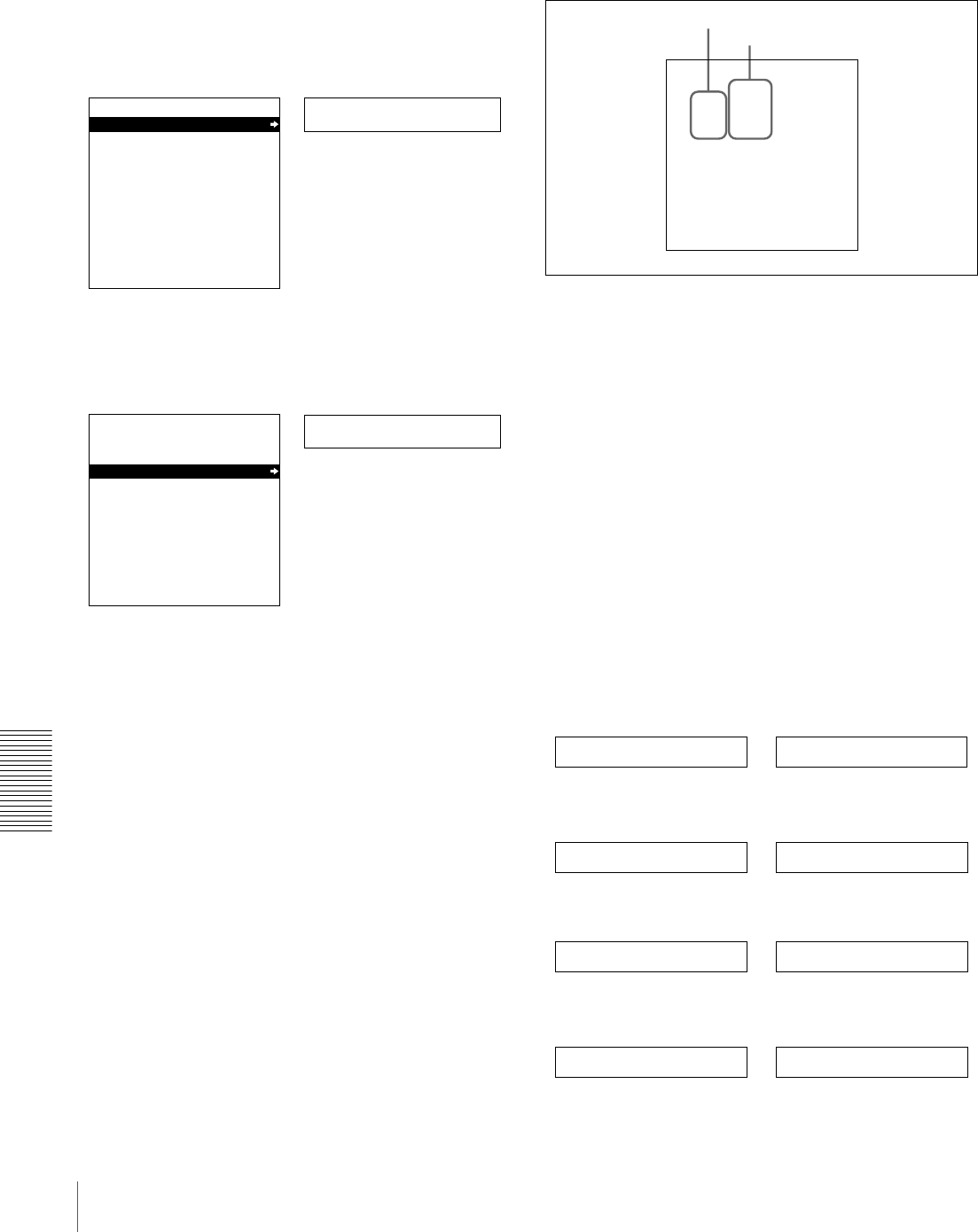
96 Maintenance
Chapter 6 Maintenance and Troubleshooting
Displaying the digital hours meter
Use the following procedure.
1Press the MENU button on the menu control panel.
The menu selection level display appears on the
monitor screen and in the time counter display.
2Press the j button to select “HOURS METER.”
3Press the k button.
The cumulative counts by the digital hours meter are
indicated on the monitor screen and in the time counter
display.
Digital hours meter indications on the monitor
screen
All four counts (T1, T2, T3, and CT) are indicated on the
monitor screen.
The four-digit value to the left of the slash (/) is the
resettable trip count, and the right value is the cumulative
total from manufacture.
Digital hours meter indications in the time
counter display
One of the four indications appears in the time counter
display at a time. Use the J and j buttons on the menu
control panel to change the item displayed.
Initially, only the trip value appears. Hold down the k
button to display also the cumulative total from
manufacture, which will appear to the right of the trip
value and the slash (/).
The following illustrates the digital hours meter
indications in the time counter display in all four display
modes. The right-hand indication for each display mode is
the indication you can view while holding down the k
button on the menu control panel.
T1 (OPERATION) mode:
T2 (DRUM ROTATION) mode:
T3 (TAPE RUNNING) mode:
CT (THREADING) mode:
Setup menu
SYSTEM MENU
SETUP MENU
AUTO FUNCTION
HOURS METER
Monitor screen
Time counter display
Menu selection level display
Hours meter
SYSTEM MENU
SETUP MENU
AUTO FUNCTION
HOURS METER
Monitor screen
Time counter display
HOURS METER
T1 00000 X10 HOURS
T2 0000/00000 X10 HOURS
T3 0000/00000 X10 HOURS
CT 0000/00000 X10 COUNT
T1:OPERATION
T2:DRUM ROTATION
T3:TAPE RUNNING
CT:THREADING
Resettable trip counts
Unresettable counts
Oper. 00000
Drum 0000 0000/00000
Tape 0000 0000/00000
Thread 0000 0000/00000

97
Maintenance
Chapter 6 Maintenance and Troubleshooting
To end the digital hours meter display
Press the MENU button on the menu control panel.
To reset the trip values
About this operation, consult your Sony dealer.
Head Cleaning
Always use the DVM12CL (mini size) or DV12CL
(standard size) Cleaning Cassette to clean the video and
audio heads. You can run the cleaning cassette for 10
seconds per cleaning operation. Follow the instructions for
the cleaning cassette, as inappropriate use of the cleaning
cassette can damage the heads.
To clean the heads
Insert the cleaning cassette. This automatically starts
cleaning. You cannot operate any tape transport control
buttons other than the EJECT button during the cleaning
operation.
After about 10 seconds, the cleaning cassette will be
automatically ejected.
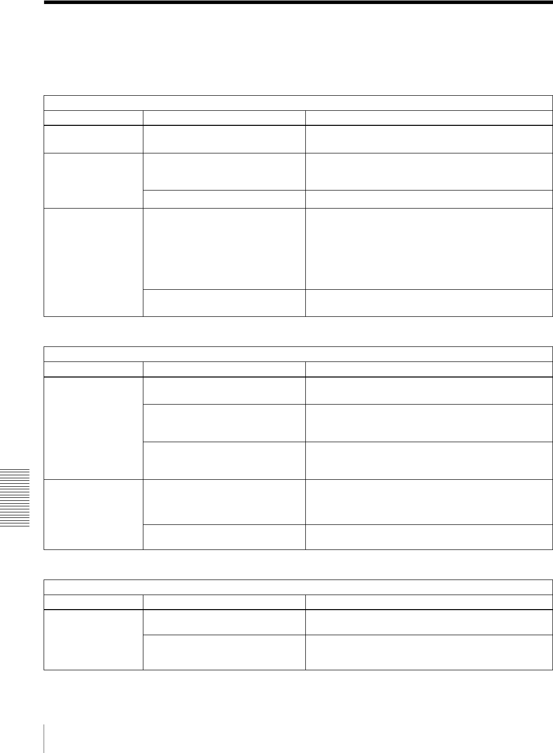
98 Troubleshooting
Chapter 6 Maintenance and Troubleshooting
Troubleshooting
If an alarm message appears on the monitor screen, or if
the unit appears to be malfunctioning, please check the
following before contacting your Sony dealer.
a) In these states, an alarm message appears on the monitor screen and in the
time counter display.
a) In these states, an alarm message appears on the monitor screen and in the
time counter display.
Tape problems
Symptom Cause Remedy
Recording is not
possible.
The cassette’s REC/SAVE switch is set
to SAVE. a)
Set the REC/SAVE switch to REC, or use another cassette.
The unit’s tape
transport control
buttons (PLAY, F FWD,
REW, etc.) do not
work.
The REMOTE button is lit and the
LOCAL ENABLE menu item is set to
STOP & EJECT or ALL DISABLE. a)
Press the REMOTE button to turn it off, or change the setting
of the LOCAL ENABLE menu item (see page 63) to ALL
ENABLE.
No cassette is loaded. a) Insert a cassette (see page 29).
The NOT EDITABLE
indicator on the front
panel lights up.
The audio recording mode selected on
this unit does not coincide with that of
the loaded tape. a)
• When your current purpose is editing, press the REMOTE
button to turn it off and set the unit for the same audio
recording mode as with the tape using the REC. MODE
menu item (see page 69), then turn on the REMOTE
button again.
• When your current purpose is recording, you can use the
tape currently loaded in the unit.
The recording format of the currently
loaded tape is “DV” or “DVCPRO.” a)
Replace the tape with one recorded in the DVCAM format.
Time data problems
Symptom Cause Remedy
Cannot freely set the
initial time data value.
The TC MODE menu item is set to EXT
REGEN. a)
Change the setting of the TC MODE menu item (see page
66) to INT PRESET.
CNT is selected as the time data type
to be displayed (the COUNTER time
data type indicator is lit). a)
Press the COUNTER SEL button to make the TC or U-BIT
time data type indicator light up (the CNT value cannot be
set freely).
The REMOTE button is lit and the
LOCAL ENABLE menu item is set to
STOP & EJECT or ALL DISABLE. a)
Press the REMOTE button to turn it off or change the setting
of the LOCAL ENABLE menu item (see page 63) to ALL
ENABLE.
The tape is running,
but the time data is not
shown in the time
counter display.
The MENU button or TC PRESET
button on the menu control panel has
been pressed.
Press the button once again to exit the menu control mode,
time code preset mode, or digital hours meter display mode.
(In either of the menu control mode and time code preset
mode, the time data is not shown in the time counter display.)
The U-BIT time data type indicator is lit. Press the COUNTER SEL button to make the COUNTER or
TC time data type indicator light up.
Monitor problems
Symptom Cause Remedy
Data is not
superimposed on the
monitor screen.
The CHARA. DISPLAY menu item is
set to OFF.
Set the CHARA. DISPLAY menu item (see page 65) to ON.
The monitor is not connected to the
VIDEO OUT 2 (SUPER) connector of
this unit.
Connect the monitor to the VIDEO OUT 2 (SUPER)
connector. (You must make this connection to display any
type of text on the monitor.)
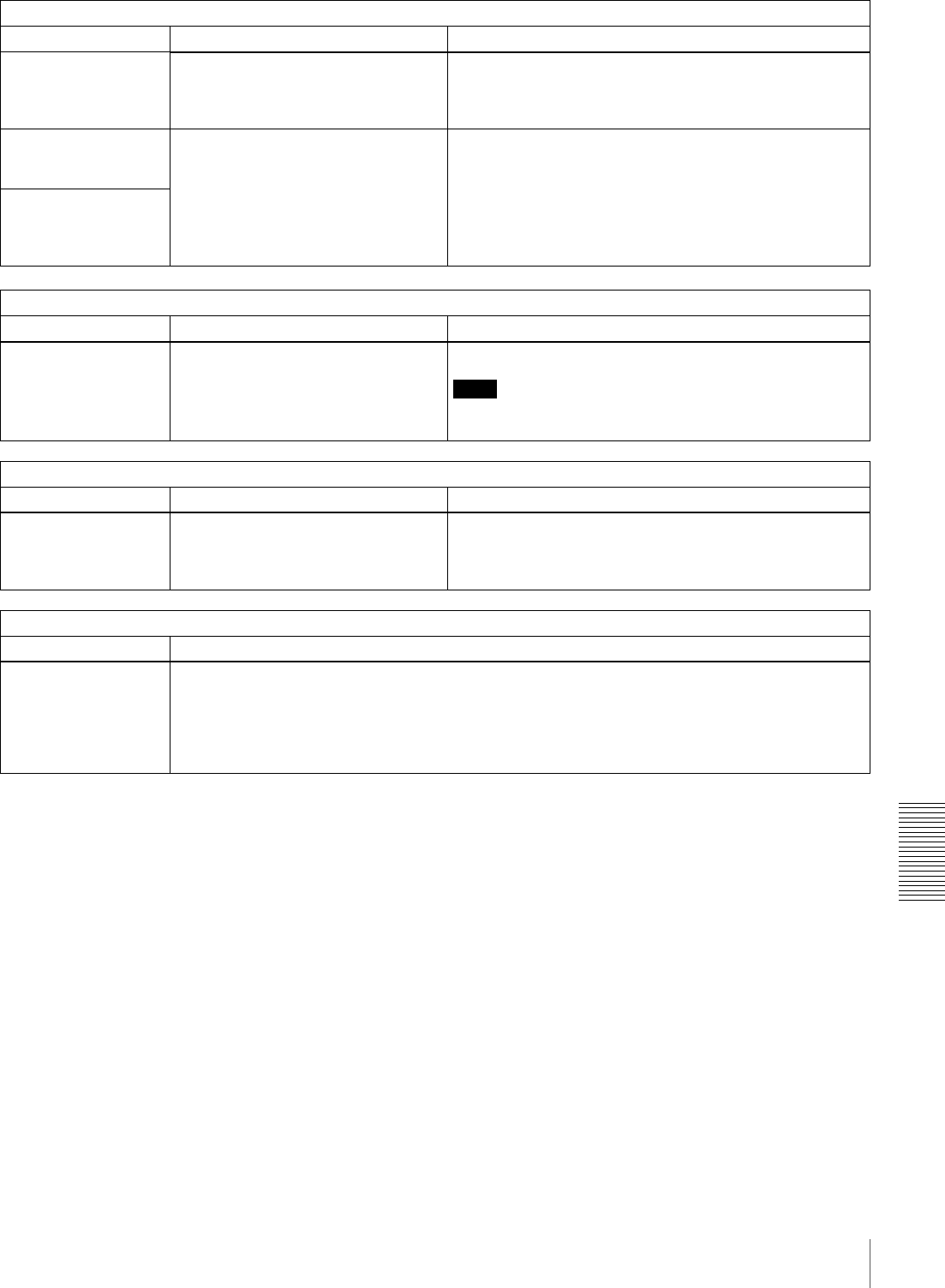
99
Troubleshooting
Chapter 6 Maintenance and Troubleshooting
The image on the
monitor screen is too
bright.
The 75 Ω termination switch for video
input on the monitor is in the OFF
position, or a 75 Ω terminator is not
fitted to its video input connector.
Set the 75 Ω termination switch to ON or connect a
terminator.
The image on the
monitor screen is too
dark.
In a video signal loop-through
connection of video monitors, 75 Ω
termination switches for video input on
monitors other than the loop-end
monitor are in the ON position.
Set the 75 Ω termination switches to OFF on all monitors
other than the loop-end monitor.
The image is too dark
when recording a
composite video
signal.
Audio problem
Symptom Cause Remedy
The AUDIO INPUT
LEVEL control knobs
do not work.
The REC LEVEL menu item is set to
PRESET.
Set the REC LEVEL menu item (see page 70) to VARIABLE.
Note
To be able to perform this operation, it is necessary to set the
MENU GRADE menu item (see page 73) to ENHANCED.
i.LINK interface problems
Symptom Cause Remedy
This unit cannot be
recognized or
controlled by computer
via i.LINK interface.
Performance of i.LINK interface is not
guaranteed with all IEEE 1394 devices.
It is only guaranteed as a tape dubbing
facility between VTRs.
• Check the computer for connections and setup.
• Contact your computer hardware/software manufacturer to
check system requirements and product compatibility.
Editing restriction
Symptom Cause
Execution of video
editing in insert mode
erases subcode data
(user bit data, etc.)
recorded on tape other
than time code data.
This phenomenon cannot be avoided with an editing system using this unit as the recorder.
Monitor problems
Symptom Cause Remedy
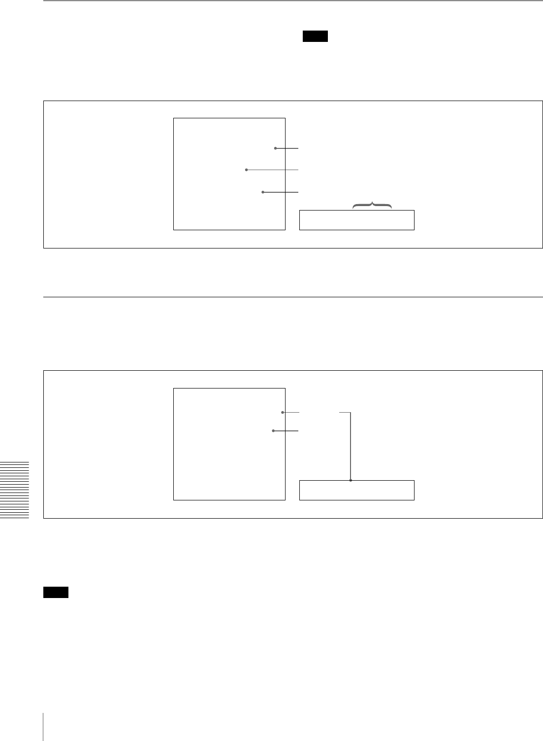
100 Troubleshooting
Chapter 6 Maintenance and Troubleshooting
Error Messages
This unit is provided with a self-diagnostic function that
detects internal abnormalities. When it detects an
abnormality, it outputs an error message to the monitor
screen and indicates an error code in the time counter
display.
Note
To display error messages on the monitor screen, connect
the monitor to the VIDEO OUT 2 (SUPER) connector, and
set the CHARA. DISPLAY menu item (see page 65) to
ON (factory default setting).
If an error message appears, follow the direction indicated
on the monitor screen.
Alarm Messages
When operating this unit, the unit may sometimes output
alarm messages such as the one shown below to the
monitor screen and the time counter display.
If such an alarm message appears, a connection or
operation error may have been made, or condensation on
heads may have occurred. Follow the direction indicated
on the monitor screen.
Note
To display alarm messages on the monitor screen, it is
necessary for the monitor to be connected to the VIDEO
OUT 2 (SUPER) connector, and set the following menu
items to ON.
• CHARA. DISPLAY (see page 65)
•ALARM (see page 66)
Error02-603
ERROR
AN ERROR HAS BEEN
DETECTED. INFORM SERVICE
OF FOLLOWING CODE:
02-603
PRESS EJECT KEY
TO EJECT TAPE.
Time counter display
Error message
Error code
Direction
Error code
Monitor screen
REMOTE!
ALARM
REMOTE MODE IS SELECTED
PRESS REMOTE BUTTON
TURNING IT OFF
Monitor screen Time counter display
Direction
Cause of
alarm
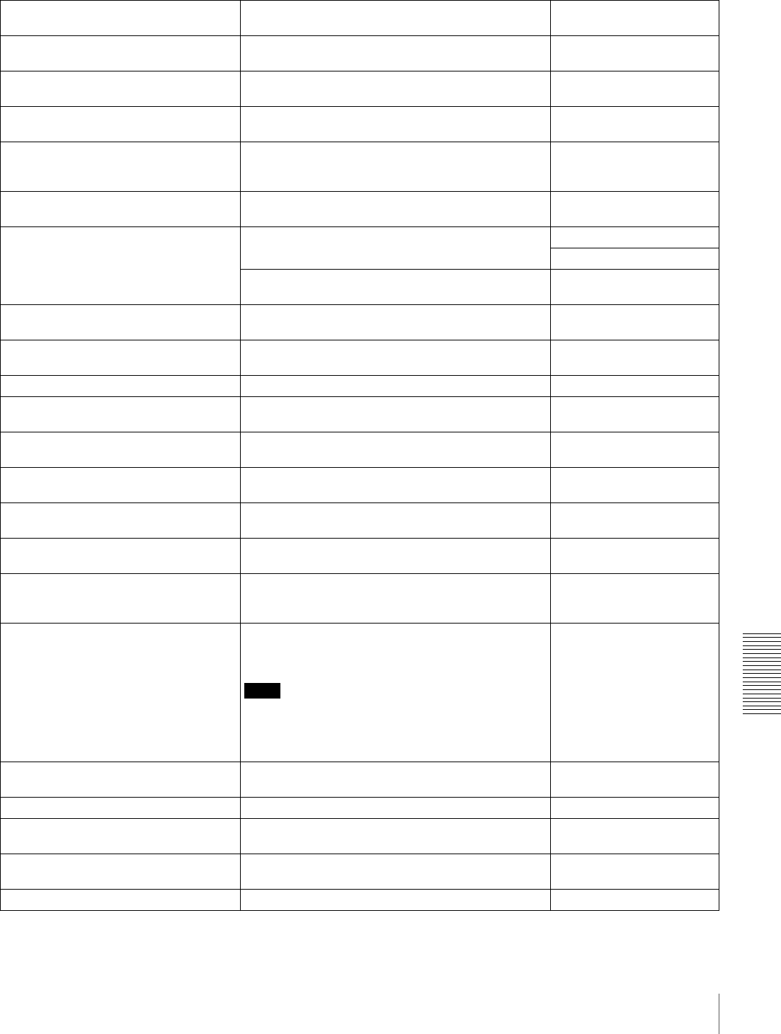
101
Troubleshooting
Chapter 6 Maintenance and Troubleshooting
Alarm messages and associated directions
Alarm message on monitor screen
(Cause) Direction Alarm message in time
counter display
A cleaning tape has been inserted. The tape will automatically be ejected after cleaning is
completed.
Cleaning Tp
A non-standard signal is being used for
input video.
Use a standard signal. VIN NON-STD
A non-standard ref. signal is being used
for REF. VIDEO.
Use a standard signal. REF NON-STD
Abnormal settings selected in setup
menu.
Correct the setup menu settings. Contact your Sony
dealer if this alarm message appears again after
making corrections.
ILL. SETUP!
Audio mixing mode cannot be changed
during recording.
−REC mode!
Audio not editable on this tape. Use a tape recorded in 2-channel/48 kHz or
4-channel/32 kHz mode.
2CH/32kHz!
Fs 44.1kHz!
Use a tape having audio signals recorded in locked
mode.
UNLOCK mode
Audio REC mode selection different from
audio on tape.
Select the same audio recording mode as that of the
tape.
A mode err
Audio REC (recording) mode cannot be
changed during recording.
−REC mode!
Cassette adaptor not usable. Use a tape without cassette adaptor. Adaptor!
Counter mode is selected. Use the COUNTER SEL button to light the TC or U-
BIT time data type indicator in the display section.
CNT mode!
Input selection cannot be changed in
REC (recording) mode.
−REC mode!
Input signal does not conform to
DVCAM/DV format.
−Unknown Sig
Input signal is 625/50. (For DSR-1800A) −625/50 sig! (For DSR-
1800A)
Input signal is 525/60. (For DSR-
1800AP)
−525/60 sig! (For DSR-
1800AP)
Input video is not detected. Check the VIDEO display in the input selection/audio
mode display section and supply an appropriate video
signal.
No INPUT!
Input video signal does not synchronize
with REF. VIDEO signal.
Use a reference video signal or connect the recorder
REF. VIDEO OUT connector to the player REF.
VIDEO IN connector.
Note
When connecting the recorder REF. VIDEO OUT
connector to the player REF. VIDEO IN connector, set
the STD/NON-STD menu item (see page 68) to
FORCED NON-STD.
ILL. REF!
Moisture has been detected. Keep the power on and wait until this alarm message
disappears.
HUMID!
No cassette in VTR. Load a cassette. No Cass.!
Rec inhibit mode is selected. Set the REC INHIBIT menu item (see page 63) to
OFF.
REC INHI.!
Record inhibit plug on the cassette is set
to inhibit.
Set the REC/SAVE switch on the cassette to REC. REC INHI.!
Remote mode is selected. Turn off the REMOTE button. REMOTE!
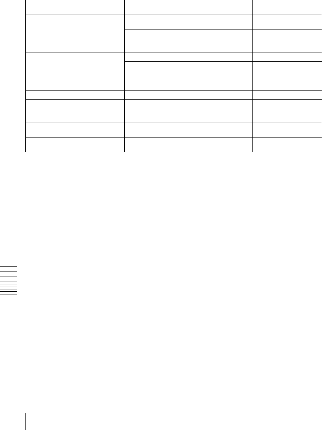
102 Troubleshooting
Chapter 6 Maintenance and Troubleshooting
Tape cannot be replayed. Use a tape recorded in 525/60 format. (For DSR-
1800A)
625/50 Tape (For DSR-
1800A)
Use a tape recorded in 625/50 format. (For DSR-
1800AP)
525/60 Tape (For DSR-
1800AP)
Tape end has been detected. Use a new cleaning tape. Tape end!
Tape not editable. Use a tape recorded in DVCAM format. Not DVCAM!
Use a tape recorded in 525/60 format. (For DSR-
1800A)
625/50 Tape (For DSR-
1800A)
Use a tape recorded in 625/50 format. (For DSR-
1800AP)
525/60 Tape (For DSR-
1800AP)
Tape not recordable. Use a DVCAM/DV ME tape. REC INHI.!
Tape not usable. Use a DVCAM/DV/DVCPRO (25M) tape. ILL. Tape!
TC EXTERNAL is selected. Set the TC MODE menu item (see page 66) to INT
PRESET.
TC EXT!
TCG REGEN mode is selected. Set the TC MODE menu item (see page 66) to INT
PRESET.
REGEN mode!
TCG RUN mode is set to REC RUN. Set the RUN MODE menu item (see page 66) to
FREE RUN.
REC RUN!
Alarm messages and associated directions
Alarm message on monitor screen
(Cause) Direction Alarm message in time
counter display

103
Precautions
Appendixes
Precautions
On safety
• Should any liquid or solid object fall into the cabinet,
unplug the unit and have it checked by qualified
personnel before operating it further.
• Unplug the unit from the wall outlet if it is not to be used
for an extended period of time.
• To disconnect the cord, pull it out by the plug. Never pull
the cord itself.
On operation and storage locations
Avoid operation or storage in any of the following places.
• Location subject to extremes of temperature (operating
temperature range 5ºC to 40ºC (41ºF to 104ºF))
• Location subject to direct sunlight for long periods, or
close to heating appliances (Note that the interior of a car
left in summer with the windows closed can exceed 50ºC
(122ºF).)
• Damp or dusty places
• Location subject to severe vibrations
• Location near equipment generating strong
electromagnetic emissions
• Location near transmitting stations generating strong
radio waves
Operate the unit in a horizontal position
This unit is designed to be operated in a horizontal
position. Do not operate it on its side, or tilted through an
excessive angle (exceeding 20º).
Avoid violent impacts
Dropping the unit, or otherwise imparting a violent shock
to it, is likely to cause it to malfunction.
Do not obstruct ventilation openings
To prevent the unit from overheating, do not obstruct
ventilation openings, by for example wrapping the unit in
a cloth while it is in operation.
On cleaning
If the casing or panel is dirty, wipe it gently with a soft dry
cloth. In the event of extreme dirt, use a cloth steeped in a
neutral detergent to remove the dirt, then wipe with a dry
cloth. Applying alcohol, thinners, insecticides, or other
volatile solvents may result in deforming the casing or
damaging the finish.
On repacking and shipping
Save the original shipping carton and packing material;
they will come in handy if you ever have to ship your unit.
For maximum protection, repack your unit as it was
originally packed at the factory, and take care not to impart
violent shocks in transit.
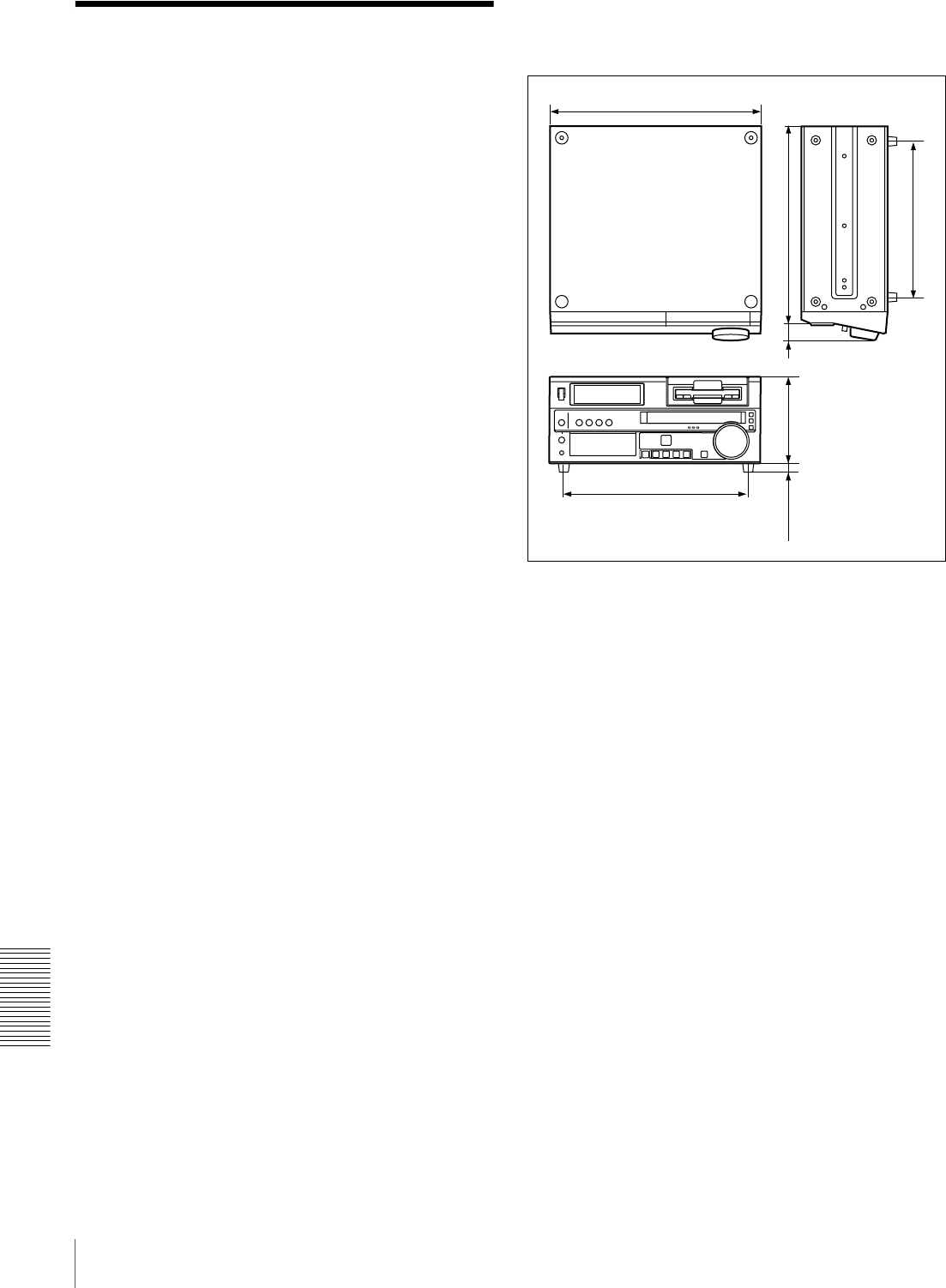
104 Specifications
Appendixes
Specifications
General
Signal system DSR-1800A: NTSC
DSR-1800AP: PAL
Power requirements
100 V to 240 V AC, 50/60 Hz
Power consumption (with all options installed)
DSR-1800A:
100 W/120 V
DSR-1800AP for Europe:
100 W/220 V
DSR-1800AP for USA and Canada:
100 W/120 V
Peak inrush current
(1)Power ON, current probe method:
40 A (100 V), 40 A (240 V)
(2)Hot switching inrush current,
measured in accordance with
European standard EN55103-1:
40 A (230 V)
Operating temperature
5ºC to 40ºC (41ºF to 104ºF)
Storage temperature
−20ºC to +60ºC (−4ºF to +140ºF)
Operating relative humidity
Less than 80%
Storage relative humidity
Less than 90%
Mass 13 kg (28 lb 10 oz)
Dimensions (w/h/d, excluding projections)
427 × 174 × 400 mm
(167/8 × 67/8 × 153/4 inches)
Tape transport control system
Tape speed DSR-1800A: 28.193 mm/s
DSR-1800AP: 28.221 mm/s
Recording/playback time
Using PDV-184ME standard-size
cassette:
Maximum 184 minutes
Using PDVM-40ME mini-size cassette:
Maximum 40 minutes
Fast forward/rewind time
Using PDV-184ME standard-size
cassette:
Less than 3 minutes
Using PDVM-40ME mini-size cassette:
Less than 1 minute
Search speed When controlling via RS-422A interface:
Maximum 60 times normal speed in
both directions
When controlling from DSRM-10
Remote Control Unit:
Jog mode: 0 (still) to 2 times normal
speed in both directions
Shuttle mode: 8 speeds from 0 (still) to
16 times normal speed in both
directions
320(12 5/8)
400(15 3/4)
34(1 3/8)
174(6 7/8)
18(23/32)
372(14 3/4)
427(16 7/8)
Unit: mm (inches)

105
Specifications
Appendixes
Video performance
Band width Composite (DSR-1800A):
30 Hz to 4.2 MHz ±1.0 dB (Y)
Composite (DSR-1800AP):
25 Hz to 4.8 MHz ±1.0 dB (Y)
S-video (DSR-1800A):
30 Hz to 5.0 MHz ±1.0 dB (Y),
5.75 MHz +0/−3.0 dB (Y) (TM)
S-video (DSR-1800AP):
25 Hz to 5.0 MHz ±1.0 dB (Y),
5.5 MHz +1.0/−2.0 dB (Y),
5.75 MHz +0/−3.0 dB (Y) (TM)
Component (DSR-1800A):
30 Hz to 5.0 MHz ±1.0 dB (Y),
5.75 MHz +0/−3.0 dB (Y) (TM),
30 Hz to 1.3 MHz ±1.0 dB (C),
1.5 MHz +0/−5.0 dB (C)
Component (DSR-1800AP):
25 Hz to 5.0 MHz ±1.0 dB (Y),
5.5 MHz +1.0/−2.0 dB (Y),
5.75 MHz +1.0/−3.0 dB (Y) (TM),
25 Hz to 1.5 MHz ±1.0 dB (C),
2.0 MHz +1.0/−2.0 dB (C)
S/N Composite I/O (Y):
53 dB or more
S-video I/O (Y): 55 dB or more
Component I/O (Y): 55 dB or more
Y/C delay 30 ns or less
K-factor 2.0% or less (K2T, KPB)
Processor adjustment range
Video level ±3 dB/−∞ to 3 dB selectable
Chrome level ±3 dB/−∞ to 3 dB selectable
Setup/Black level
±30 IRE (±210 mV)
Chroma phase ±30°
Y/C delay ±100 ns
System phase Sync: ±1 μs *
SC: ±180°
*+2 μs to -3 μs when using a TBC remote control unit
Audio performance
Frequency response
Two-channel (48 kHz) mode:
20 Hz to 20 kHz +0.5 dB/−1.0 dB
Four-channel (32 kHz) mode:
20 Hz to 14.5 kHz +0.5 dB/−1.0 dB
Dynamic range More than 90 dB
Distortion (THD + N)
Less than 0.05% (48 kHz)
Input connectors
Digital signal inputs
SDI IN (with optional DSBK-1801 SDI/AES/EBU Input/
Output Board installed)
BNC type (×2, active-through), Serial
Digital Interface format (270 Mbps),
SMPTE 259M/ITU-R BT.656
DV IN/OUT 6-pin IEEE 1394 connector
Analog video inputs
REF. VIDEO IN
BNC type (×2, loop-through)
Black burst
0.286 Vp-p (DSR-1800A) or 0.3 Vp-p
(DSR-1800AP), 75 Ω, negative sync
Composite sync
VIDEO IN BNC type (×2, loop-through), composite,
1.0 Vp-p, 75 Ω, sync negative
COMPONENT VIDEO IN
BNC type (×3)
Y: 1.0 Vp-p, 75 Ω, negative sync
R−Y/B−Y: 0.7 Vp-p (75% color bars
for DSR-1800A or 100% color bars for
DSR-1800AP), 75 Ω
S VIDEO IN DIN 4-pin
Y: 1.0 Vp-p, 75 Ω
C: 0.286 Vp-p (DSR-1800A) or
0.3 Vp-p (DSR-1800AP), 75 Ω (burst
level)
Analog audio inputs
AUDIO IN XLR 3-pin, female (×4), +4/0/−3 */−6
dBu, 600 Ω ON/OFF/−60 dBu, high
impedance, balanced
* Selectable on DSR-1800AP only
Digital audio inputs
DIGITAL AUDIO (AES/EBU) IN (with optional DSBK-
1801 SDI/AES/EBU Input/Output Board installed)
BNC type (×2), complying with AES-
3id-1995
Time code input
TIME CODE IN
BNC type, SMPTE time code (DSR-
1800A) or EBU time code (DSR-
1800AP), 0.5 Vp-p to 18 Vp-p, 3.3 kΩ,
unbalanced
Output connectors
Digital signal outputs
SDI OUT (with optional DSBK-1801 SDI/AES/EBU
Input/Output Board installed)
BNC type (×2, active-through), Serial
Digital Interface format (270 Mbps),
SMPTE 259M/ITU-R BT.656

106 Specifications
Appendixes
DV IN/OUT 6-pin IEEE 1394 connector
Analog video outputs
REF. VIDEO OUT
BNC type ×1
Black burst
0.286 Vp-p (DSR-1800A) or 0.3 Vp-p
(DSR-1800AP), 75 Ω, negative sync
Composite sync
VIDEO OUT 1, 2 (SUPER)
BNC type (×2), composite, 1.0 Vp-p,
75 Ω, sync negative
COMPONENT VIDEO OUT
BNC type (×3), Y/R−Y/B−Y
Y: 1.0 Vp-p, 75 Ω, sync negative
R−Y: 0.7 Vp-p, 75 Ω (75% color bars for
DSR-1800A or 100% color bars for
DSR-1800AP)
B−Y: 0.7 Vp-p 75 Ω (75% color bars for
DSR-1800A or 100% color bars for
DSR-1800AP)
S VIDEO OUT DIN 4-pin
Y: 1.0 Vp-p, 75 Ω, sync negative
C: 0.286 Vp-p (DSR-1800A) or 0.3 Vp-p
(DSR-1800AP), 75 Ω (burst level)
Analog audio outputs
AUDIO OUT XLR 3-pin, male (× 4), +4/0/−3 */−6 dBu,
600 Ω loading, low impedance,
balanced
AUDIO MONITOR OUT
Phono jack, 47 kΩ, unbalanced
−∞ to −11 dBu ±1 dBu, −20 dBFS
(DSR-1800A)
−∞ to −9 dBu ±1 dBu, −18 dBFS
(DSR-1800AP)
* Selectable on DSR-1800AP only
Digital audio outputs
DIGITAL AUDIO (AES/EBU) OUT (with optional
DSBK-1801 SDI/AES/EBU Input/Output Board installed)
BNC type (×2), complying with AES-
3id-1995
Output for headphones
HEADPHONES
Stereo phone jack, 8 Ω, unbalanced
−∞ to −13 dBu, −20 dBFS
(DSR-1800A)
−∞ to −11 dBu, −18 dBFS
(DSR-1800AP)
Time code output
TIME CODE OUT
BNC type, SMPTE time code (DSR-
1800A), EBU time code (DSR-
1800AP), 2.2 Vp-p ±3 dB, 600 Ω,
unbalanced
Remote control connectors
REMOTE D-sub 9-pin, female, for connection of
editing control unit, RS-422A standard
CONTROL S Stereo minijack, for connection of
SIRCS-compatible remote control unit
(DSRM-10)
VIDEO CONTROL
D-sub 15-pin, male, for connection of
TBC remote control unit
DV IN/OUT 6-pin IEEE 1394 connector
Supplied accessories
AC power cord (1)
Operating Instructions
English version (1)
CD-ROM manual (1)
Optional accessories
DSBK-1801 SDI/AES/EBU Input/Output Board
RCC-5G 9-pin remote control cable (length: 5 m (16 ft))
RMM-131/1 Rack Mount Kit
Digital video cassette
Standard size: PDV-34*/64*/94*/124*/
184* a)
Mini size: PDVM-12*/22*/32*/40* a)
a) The * in each model name is actually “ME”
(indicating that a cassette memory is contained), or
“N” (indicating that no cassette memory is
contained).
Cleaning cassette
DV12CL (standard size), DVM12CL
(mini size)
Design and specifications are subject to change without
notice.
Notes
• Always make a test recording, and verify that it was
recorded successfully.
SONY WILL NOT BE LIABLE FOR DAMAGES OF
ANY KIND INCLUDING, BUT NOT LIMITED TO,
COMPENSATION OR REIMBURSEMENT ON
ACCOUNT OF FAILURE OF THIS UNIT OR ITS
RECORDING MEDIA, EXTERNAL STORAGE
SYSTEMS OR ANY OTHER MEDIA OR
STORAGE SYSTEMS TO RECORD CONTENT OF
ANY TYPE.
• Always verify that the unit is operating properly before
use.
SONY WILL NOT BE LIABLE FOR DAMAGES OF
ANY KIND INCLUDING, BUT NOT LIMITED TO,
COMPENSATION OR REIMBURSEMENT ON
ACCOUNT OF THE LOSS OF PRESENT OR
PROSPECTIVE PROFITS DUE TO FAILURE OF
THIS UNIT, EITHER DURING THE WARRANTY
PERIOD OR AFTER EXPIRATION OF THE
WARRANTY, OR FOR ANY OTHER REASON
WHATSOEVER.

107
Glossary
Appendixes
Glossary
A/B roll editing
An editing method that uses two or
more playback VCRs to create
special effects such as dissolve and
wipe, and uses one record VCR to
record the results of the editing.
Using an editing control unit allows
efficient control of the VCRs and
very precise editing.
AES/EBU format
A unified format for digital audio
signals. It allows a single connector
to carry the signals for two channels.
B−Y signal
A chrominance signal determined by
subtracting the Y (luminance) signal
from the B (blue) signal. One of the
component signals.
Capstan
A drive mechanism that moves the
tape at a specified speed. Its rotation
normally synchronizes with a
reference sync signal.
Chrominance signal
Color signal containing color
information such as hue and
saturation. Also called C signal.
Component signals (YRB)
A video signal consisting of a
luminance signal (Y) and two
chrominance signals (R−Y, B−Y).
Composite signal
A composite video signal containing
video, burst and sync signals.
Condensation
Condensation of moisture on the tape
transport mechanisms of VCRs
including the head drum. If moisture
condenses on the head drum, the tape
adheres to the drum and causes
malfunction.
Drop frame mode
Time code runs at 30 frames/sec. The
NTSC system, however, runs at
about 29.97 frames/sec. Drop frame
mode adjusts this difference. The
time code and video are synchronized
by dropping the first two frames of
the time code every minute, except at
the ten-minute marks.
EE mode
EE is an abbreviation of “Electric to
Electric”. Video and audio signals are
supplied to the VCR’s internal
circuits, but not to the recording
heads.
Head drum
A metal cylinder to which a video
head is attached. This drum is rotated
at high speeds in synchronization
with the sync signal during recording
and playback.
Linear editing
Editing while playing back video and
audio signals recorded on video tape.
See also “Non-linear editing.”
Loading
When being loaded, the tape is pulled
out of the cassette case and threaded
along the specified tape path and
wrapped round the drum to be ready
for recording or playback. Generally,
this is done automatically when you
place the cassette at the cassette
entrance of the VCR. Also called
threading.
Loop-through connection
A connection which allows a signal
input to an input connector to pass
through the unit and exit from an
output connector as input to external
equipment. Also called bridging
connection.
Luminance signal
The signal that determines the
brightness of the picture. Also called
Y signal. One of the component
signals.
Non-drop frame mode
The number of frames of the time
code and video run is not adjusted.
When you use the time code in non-
drop frame mode, the real playback
time will be about 86 seconds shorter
per day than the time code. If you edit
frame by frame or if you determine
the length of a shot by counting the
time code, use drop frame mode.
Non-linear editing
Editing while playing back video and
audio signals recorded on hard disks.
Video scenes stored on disk can be
cued up quickly, for increased editing
efficiency. See also “Linear
editing.”
PCM audio
This is an audio signal represented by
pulse code modulation. The analog
audio signal is first broken down into
a sequence of pulses, and these are
then represented digitally.
Preroll
Running of a video tape to a prior to
an edit-start point to enable the tape
to reach a steady speed and to be
synchronized with other video tapes.
R−Y signal
A chrominance signal determined by
subtracting the Y (luminance) signal
from the R (red) signal. One of the
component signals.
Reference video signal
A video signal consisting of a sync
signal or sync and burst signals, used
as a reference.
Setup (for DSR-1800A)
The difference between the reference
black level and the blanking level of
a composite signal.
SMPTE
Abbreviation of Society of Motion
Picture and Television Engineers, a
professional association established
in the USA.

108 Glossary
Appendixes
S/N
Abbreviation of Signal-to-Noise
(ratio). The higher the S/N value, the
less noise and higher the picture
quality.
Search mode
A VCR operating mode used when
searching for specific scenes, by
viewing the video output or time code
values while playing back the tape at
various speeds in forward or reverse
direction.
Servo lock
Synchronizing the drum rotation
phase and tape transport phase with a
reference signal during playback and
recording so that the video heads scan
the tape in the same pattern during
playback and recording.
Standby Off mode
One of two conditions in the stop
mode. The drum does not rotate and
tape is slackened. There is no damage
to the video heads and the tape, but
the VCR is not ready for immediate
recording or playback.
Standby On mode
One of two conditions in the stop
mode. The drum is rotating and the
tape is wrapped round the drum. The
VCR is ready for recording or
playback, so a still picture can be
obtained.
Subcarrier
A sine wave imposed on the
luminance portion of a video signal
and modulated to carry color
information. Its amplitude represents
color saturation and its phase
represents hue.
Superimpose
To put a set of characters onto a
picture so that both can be seen at the
same time.
S-video
A signal format in which Y
(luminance) and C (chrominance)
signals are separated to reduce
interference between them so that
noiseless images are reproduced.
Sync signal
A reference signal consisting of
vertical and horizontal sync signals
used for synchronizing the scanning
patterns of the video camera and the
monitor.
TBC
Abbreviation of Time Base
Corrector. Electronic circuits to
electrically stabilize the playback
signals by removing color variation
and roll in the playback picture
caused by irregularity in drum
rotation and tape movement. Time
base correction reduces deterioration
of picture quality when transmitting
or copying playback signals.
Threading
See “Loading.”
Time code
Signals recorded on the tape to
supply information on tape position
such as the hour, minute, second and
frame, to assist in setting edit points
or searching for particular scenes.
Unloading
When the EJECT button is pressed,
the VCR automatically winds the
tape back into the cassette case. Also
called “Unthreading.”
User bits
Sections of time code information
consisting of a total of 32 bits that can
be used for recording information
such as date, tape ID number,
program ID number, etc.

109
Index
Index
Index
Numerics
9PIN button 20
A
A/B roll editing system 86
AC IN connector 21
Alarm messages 100
Analog audio signal input/output
section 24
Analog interfaces 10
Analog recording 91
Analog video signal input/output
section 22
Arrow buttons 16
Aspect ratio 11
AUDIO CH1 1/2 display 14
AUDIO CH2 3/4 display 14
AUDIO IN CH-1 to CH-4 connectors
24
AUDIO IN LEVEL/600-ohm switches
24
AUDIO INPUT LEVEL control knobs
14
Audio level meters 13
AUDIO MONITOR OUT connector
24
Audio monitor system connections 87
AUDIO OUT CH-1 to CH-4
connectors 24
Audio performance 105
AUTO FUNCTION execution menu
75
Auto mode execution menu 75
B
Basic items 59, 76
C
Cassette compartment 13
Cassette memory indicator 19
CH1,1/2 button 16
CH2,3/4 button 16
CHANNEL CONDITION indicators
19
ClipLink indicator 18
COMPONENT VIDEO IN Y/R-Y/B-
Y connectors 22
COMPONENT VIDEO OUT Y/R-Y/
B-Y connectors 23
Condensation 95
Connections 83
analog recording 91
audio monitor system 87
control signal 88
for A/B roll editing system 86
for cut editing system 85
for digital non-linear editing
system 83
for dubbing via i.LINK interface
55
video monitor 90
video/audio signals 89
CONTROL S connector 14
Control signal connections 88
COUNTER 49
COUNTER SEL button 16
Cut editing system 85
D
DIGITAL AUDIO (AES/EBU) IN
connectors 24
DIGITAL AUDIO (AES/EBU) OUT
connectors 24
Digital dubbing 55
Digital hours meter 11, 95
display modes 95
indications in the time counter
display 96
indications on the monitor 96
Digital jog sound function 10
Digital signal input/output section 23
Digital slow-motion playback 10
Display section 18
Drop frame indication 48
DSBK-1801 SDI/AES/EBU Input/
Output Board 11
DV format 9
DVCAM format 9
DVCPRO format 9
E
EBU 10
Editing control unit 90
EE OUT PHASE settings 73
THROUGH mode 73
VIDEO INPUT PHASE mode 73
VIDEO OUTPUT PHASE mode
74
EJECT button 17
Enhanced items 59, 78
Error messages 100
External device connectors 25
F
F FWD button 17
Factory default settings 79
FREE RUN 50
Front panel 13
H
Head cleaning 97
HEADPHONES connector 14
I
i.DV IN/OUT connector 23, 32
i.LINK (DV) 10
i.LINK button 20
Initial time code value 49
INPUT display 14
INPUT SELECT section 16
Input selection/audio mode display
section 14
Interfaces 10
Internal time code generator 49
FREE RUN 50
REC RUN 50
J
JOG indicator 19
Jog mode 20, 53
Jog sound function 10
M
Maintenance 95
condensation 95
head cleaning 97
regular checks 95
Menu 59
changing settings 76
contents 62
factory default settings 79
item indications 62
Menu control panel 15
MONITOR SELECT switches 15
N
Non-linear editing 83
NOT EDITABLE indicator 19
O
Operation mode indications 47, 48
Optional accessories 106
P
PB FS display 14
PCM digital audio 9
Phases adjustment 92
PHONE LEVEL control knob 13
PLAY button 17
Playback 53

110 Index
Index
Playback modes 20
jog mode 53
shuttle mode 54
POWER switch 13
Precautions 103
Processor adjustment range 105
R
Rack mount 11
Rear panel 21
REC button 17
REC INHIBIT indicator 19
REC MODE display 14
REC RUN 50
Recording/playback format indicators
18
REF. VIDEO IN/OUT connectors 22
Reference video signals 85
Regular checks 95
REMOTE button 20
REMOTE connector 25
Remote control 10
Remote control setting section 20
REPEAT indicator 19
Rerecording time code 51
RESET (NO) button 16
REW button 17
RMM-131/1 Rack Mount Kit 11
RS-422A interface 10
S
S VIDEO IN connector 22
S VIDEO OUT connector 23
SC PHASE control 16
SDI IN connector 24
SDI OUT connectors 24
SDI/AES/EBU 10
SDTI/i.LINK button 16
Search 10, 19, 53
via external equipment 53
SEARCH button 19
Search control section 19
Search dial 19
SERVO indicator 19
SET (YES) button 16
Setup menu 62
AUDIO CONTROL 69
DIGITAL PROCESS 72
DISPLAY CONTROL 65
MENU GRADE 73
OPERATIONAL FUNCTION
62
SETUP BANK OPERATION 72
TAPE PROTECTION 68
TIME CODE 66
VIDEO CONTROL 68
SHUTTLE indicator 19
Shuttle mode 20, 54
SIRCS 10
Slow-motion playback 10
SMPTE 10
Specifications 104
STOP button 17
Subcarrier phase 92
Superimposition 11, 23
Supplementary status information 80
Sync phase 92
SYNC PHASE control 17
Synchronizing time codes 50
T
Tape end alarm indicator 19
Tape transport control section 17
TC 49
TC insert function 51
TC PRESET button 16
Time code
generator/reader 10
rerecording 51
TIME CODE IN/OUT connectors 23
Time counter display 19, 49
Time data
displaying 47
setting 47
Time data type 48
COUNTER 49
indicators 19
TC 49
U-BIT 49
Track pitch 9
Troubleshooting 98
alarm messages 100
error messages 100
U
U-BIT 49
V
VIDEO CONTROL connector 25
VIDEO display 14
VIDEO IN button 16
VIDEO IN connectors 22
Video monitor connection 90
VIDEO OUT 1 and 2 (SUPER)
connectors 23
Video performance 105
Video process control 10
Video/audio signal connections 89
VITC field indication 48
VITC indicator 18
W
Wide-screen 11

Sony Corporation http://www.sony.net/ Printed in China
