Sony Pdw F1600 Users Manual F1600/PDW HD1500
PDW-F1600 to the manual 525b57b1-dbf6-4465-8f2a-3cef65f33bbf
2015-01-23
: Sony Sony-Pdw-F1600-Users-Manual-286848 sony-pdw-f1600-users-manual-286848 sony pdf
Open the PDF directly: View PDF ![]() .
.
Page Count: 188 [warning: Documents this large are best viewed by clicking the View PDF Link!]
- Table of Contents
- Chapter 1 Overview
- Chapter 2 Names and Functions of Parts
- Chapter 3 Preparations
- Chapter 4 Recording and Playback
- Recording
- Mixed recording of clips in different formats on the same disc
- Preparations for recording
- Carrying out recording
- Continuing recording while exchanging discs (disc exchange cache function)
- Recording with the HDSDI remote control function
- Recording with the Clip Continuous Rec function
- Handling of discs when recording does not end normally (salvage functions)
- Linear Editing
- Playback
- Recording
- Chapter 5 Operations in GUI Screens
- Chapter 6 File Operations
- Chapter 7 Menus
- Chapter 8 Planning Metadata
- Appendix
- Index

PROFESSIONAL DISC RECORDER
PDW-F1600
PDW-HD1500
OPERATION MANUAL [English]
1st Edition (Revised 3)
The supplied CD-ROM includes operation manuals for the PDW-F1600/HD1500 Professional Disc
Recorder (English, Japanese, French, German, Italian, Spanish and Chinese versions) in PDF
format.
For more details, see “Using the CD-ROM Manual” on page 16.
2
• Read these instructions.
• Keep these instructions.
• Heed all warnings.
• Follow all instructions.
• Do not use this apparatus near water.
• Clean only with dry cloth.
• Do not block any ventilation openings.
Install in accordance with the manufacturer’s instructions.
• Do not install near any heat sources such as radiators, heat
registers, stoves, or other apparatus (including amplifiers)
that produce heat.
• Do not defeat the safety purpose of the polarized or
grounding-type plug. A polarized plug has two blades with
one wider than the other. A grounding-type plug has two
blades and a third grounding prong. The wide blade or the
third prong are provided for your safety. If the provided plug
dose not fit into your outlet, consult an electrician for
replacement of the obsolete outlet.
• Protect the power cord from being walked on or pinched
particularly at plugs, convenience receptacles, and the point
where they exit from the apparatus.
• Only use attachments/accessories specified by the
manufacturer.
• Use only with the cart, stand, tripod, bracket, or table
specified by the manufacturer, or sold with the apparatus.
When a cart is used, use caution when moving the cart/
apparatus combination to avoid injury from tip-over.
• Unplug this apparatus during lightning storms or when
unused for long periods of time.
• Refer all servicing to qualified service personnel. Servicing
is required when the apparatus has been damaged in any
way, such as power-supply cord or plug is damaged, liquid
has been spilled or objects have fallen into the apparatus,
the apparatus has been exposed to rain or moisture, does
not operate normally, or has been dropped.
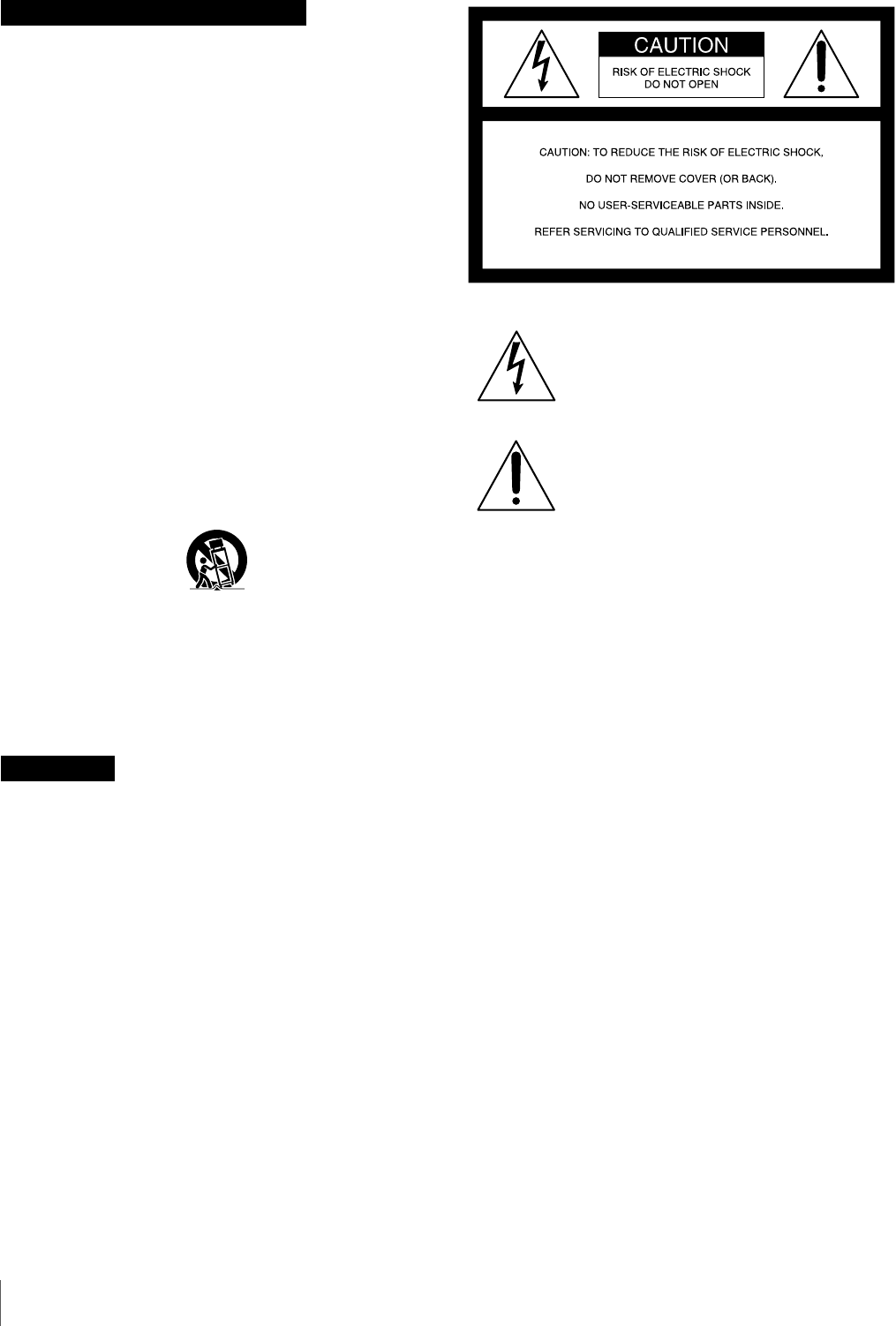
To reduce the risk of fire or electric shock,
do not expose this apparatus to rain or
moisture.
To avoid electrical shock, do not open the
cabinet. Refer servicing to qualified
personnel only.
THIS APPARATUS MUST BE EARTHED.
CAUTION
The apparatus shall not be exposed to dripping or splashing.
No objects filled with liquids, such as vases, shall be placed on
the apparatus.
The unit is not disconnected from the AC power source
(mains) as long as it is connected to the wall outlet, even if the
unit itself has been turned off.
WARNING: THIS WARNING IS APPLICABLE FOR USA
ONLY.
If used in USA, use the UL LISTED power cord specified
below.
DO NOT USE ANY OTHER POWER CORD.
Plug Cap Parallel blade with ground pin
(NEMA 5-15P Configuration)
Cord Type SJT, three 16 or 18 AWG wires
Length Minimum 1.5 m (4 ft. 11 in.), Less than
2.5 m (8 ft. 3 in.)
Rating Minimum 10 A, 125 V
Using this unit at a voltage other than 120 V may require the
use of a different line cord or attachment plug, or both. To
reduce the risk of fire or electric shock, refer servicing to
qualified service personnel.
WARNING: THIS WARNING IS APPLICABLE FOR OTHER
COUNTRIES.
1. Use the approved Power Cord (3-core mains lead)/
Appliance Connector/Plug with earthing-contacts that
conforms to the safety regulations of each country if
applicable.
2. Use the Power Cord (3-core mains lead)/Appliance
Connector/Plug conforming to the proper ratings (Voltage,
Ampere).
If you have questions on the use of the above Power Cord/
Appliance Connector/Plug, please consult a qualified service
personnel.
Important Safety Instructions
WARNING
This symbol is intended to alert the user to
the presence of uninsulated “dangerous
voltage” within the product’s enclosure that
may be of sufficient magnitude to constitute
a risk of electric shock to persons.
This symbol is intended to alert the user to
the presence of important operating and
maintenance (servicing) instructions in the
literature accompanying the appliance.
3
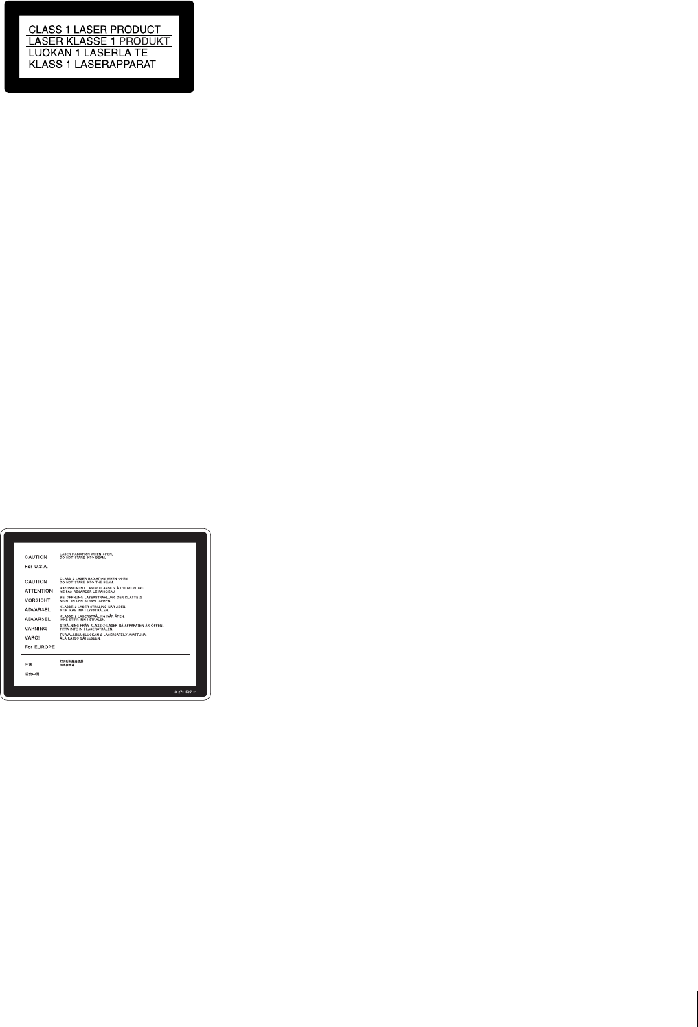
This Professional Disc Recorder is classified as a CLASS 1
LASER PRODUCT.
Laser diode properties
Wave length: 400 to 410 nm
Emission duration: Continuous
Laser output power: 135 mW (max. of pulse peak), 65 mW
(max. of CW)
Standard: IEC60825-1 (2001)
Egenskaber for laserdiode
Bølgelængde: 400 til 410 nm
Strålingsvarighed: Kontinuerlig
Afgivet lasereffekt: 135 mW (maks stråletoppunkt), 65 mW
(maks ved kontinuerlig stråling)
Standard: IEC60825-1 (2001)
Tekniska data för laserdiod
Våglängd: 400 till 410 nm
Emissionslängd: Kontinuerlig
Laseruteffekt: 135 mW (max. för pulstopp), 65 mW (max. för
kontinuerlig våg)
Standard: IEC60825-1 (2001)
Egenskaper for laserdiode
Bølgelengde: 400 til 410 nm
Strålingsvarighet: Uavbrutt
Utgangseffekt for laser: 135 mW (maks av pulshøyde), 65
mW (maks av CW)
Standard: IEC60825-1 (2001)
This label is located on the top panel of the drive unit.
Denna etikett finns på ovansidan av driftenheten.
Denne mærkat sidder på drevenhedens øverste panel.
Tämä kyltti sijaitsee ajurilaitteen yläpinnalla.
Dette merket er plassert på oversiden av driverenheten.
CAUTION
The use of optical instruments with this product will increase
eye hazard.
CAUTION
Use of controls or adjustments or performance of procedures
other than those specified herein may result in hazardous
radiation exposure.
WARNING
Excessive sound pressure from earphones and headphones
can cause hearing loss.
In order to use this product safely, avoid prolonged listening at
excessive sound pressure levels.
VAROITUS!
LAITTEEN KÄYTTÄMINEN MUULLA KUIN TÄSSÄ
KÄYTTÖOHJEESSA MAINITULLA TAVALLA SAATTAA
ALTISTAA KÄYTTÄJÄN TURVALLISUUSLUOKAN 1
YLITTÄVÄLLE NÄKYMÄTTÖMÄLLE LASERSÄTEILYLLE.
VARNING
OM APPARATEN ANVÄNDS PÅ ANNAT SÄTT ÄN I DENNA
BRUKSANVISNING SPECIFICERATS, KAN ANVÄNDAREN
UTSÄTTAS FÖR OSYNLIG LASERSTRÅLNING, SOM
ÖVERSKRIDER GRÄNSEN FÖR LASERKLASS 1.
When installing, the installation space must be secured in
consideration of the ventilation and service operation.
• Do not block the ventilation slots at the left side, right side
and bottom of front side panels, and vents of the fans.
• Leave more than 25 cm of space in the rear of the unit.
• Leave more than 2 cm of space in the left side, right side and
top of the unit.
For the customers in the USA
This equipment has been tested and found to comply with the
limits for a Class A digital device, pursuant to Part 15 of the
FCC Rules. These limits are designed to provide reasonable
protection against harmful interference when the equipment is
operated in a commercial environment. This equipment
generates, uses, and can radiate radio frequency energy and,
if not installed and used in accordance with the instruction
manual, may cause harmful interference to radio
communications. Operation of this equipment in a residential
area is likely to cause harmful interference in which case the
user will be required to correct the interference at his own
expense.
You are cautioned that any changes or modifications not
expressly approved in this manual could void your authority to
operate this equipment.
All interface cables used to connect peripherals must be
shielded in order to comply with the limits for a digital device
pursuant to Subpart B of Part 15 of FCC Rules.
This device complies with Part 15 of the FCC Rules. Operation
is subject to the following two conditions: (1) this device may
not cause harmful interference, and (2) this device must
accept any interference received, including interference that
may cause undesired operation.
For customers in Canada
This Class A digital apparatus complies with Canadian ICES-
003.
For the customers in Europe
This product with the CE marking complies with both the EMC
Directive and the Low Voltage Directive issued by the
Commission of the European Community.
4
Compliance with these directives implies conformity to the
following European standards:
• EN60065: Product Safety
• EN55103-1: Electromagnetic Interference (Emission)
• EN55103-2: Electromagnetic Susceptibility (Immunity)
This product is intended for use in the following
Electromagnetic Environment(s):
E1 (residential), E2 (commercial and light industrial), E3
(urban outdoors) and E4 (controlled EMC environment, ex. TV
studio).
For the customers in Europe
The manufacturer of this product is Sony Corporation, 1-7-1
Konan, Minato-ku, Tokyo, Japan.
The Authorized Representative for EMC and product safety is
Sony Deutschland GmbH, Hedelfinger Strasse 61, 70327
Stuttgart, Germany. For any service or guarantee matters
please refer to the addresses given in separate service or
guarantee documents.
For kundene i Norge
Dette utstyret kan kobles til et IT-strømfordelingssystem.
Laite on liitettävä suojamaadoituskoskettimilla varustettuun
pistorasiaan
Apparatet må tilkoples jordet stikkontakt
Apparaten skall anslutas till jordat uttag
For the Customers in Taiwan only
Afin de réduire les risques d’incendie ou
d’électrocution, ne pas exposer cet
appareil à la pluie ou à l’humidité.
Afin d’écarter tout risque d’électrocution,
garder le coffret fermé. Ne confier
l’entretien de l’appareil qu’à un personnel
qualifié.
CET APPAREIL DOIT ÊTRE RELIÉ À LA
TERRE.
ATTENTION
Eviter d’exposer l’appareil à un égouttement ou à des
éclaboussures. Ne placer aucun objet rempli de liquide,
comme un vase, sur l’appareil.
Cet appareil n’est pas déconnecté de la source d’alimentation
secteur tant qu’il est raccordé à la prise murale, même si
l’appareil lui-même a été mis hors tension.
Cette étiquette est placée sur le panneau supérieur de l’unité
de commande.
AVERTISSEMENT
Une pression acoustique excessive en provenance des
écouteurs ou du casque peut provoquer une baisse de l’acuité
auditive.
Pour utiliser ce produit en toute sécurité, évitez l’écoute
prolongée à des pressions sonores excessives.
Pour les clients au Canada
Cet appareil numérique de la classe A est conforme à la
norme NMB-003 du Canada.
Pour les clients européens
Ce produit portant la marque CE est conforme à la fois à la
Directive sur la compatibilité électromagnétique (EMC) et à la
Directive sur les basses tensions émises par la Commission
de la Communauté Européenne.
La conformité à ces directives implique la conformité aux
normes européennes suivantes :
• EN60065 : Sécurité des produits
• EN55103-1 : Interférences électromagnétiques (émission)
• EN55103-2 : Sensibilité électromagnétique (immunité)
Ce produit est prévu pour être utilisé dans les environnements
électromagnétiques suivants :
E1 (résidentiel), E2 (commercial et industrie légère),
E3 (urbain extérieur) et E4 (environnement EMC contrôlé ex.
studio de télévision).
AVERTISSEMENT
1.Utilisez un cordon d’alimentation (câble secteur à 3 fils)/
fiche femelle/fiche mâle avec des contacts de mise à la terre
conformes à la réglementation de sécurité locale applicable.
2.Utilisez un cordon d’alimentation (câble secteur à 3 fils)/
fiche femelle/fiche mâle avec des caractéristiques
nominales (tension, ampérage) appropriées.
Pour toute question sur l’utilisation du cordon d’alimentation/
fiche femelle/fiche mâle ci-dessus, consultez un technicien du
service après-vente qualifié.
Pour les clients en Europe
Le fabricant de ce produit est Sony Corporation, 1-7-1 Konan,
Minato-ku, Tokyo, Japon.
Le représentant autorisé pour EMC et la sécurité des produits
est Sony Deutschland GmbH, Hedelfinger Strasse 61, 70327
Stuttgart, Allemagne. Pour toute question concernant le
service ou la garantie, veuillez consulter les adresses
indiquées dans les documents de service ou de garantie
séparés.
AVERTISSEMENT
5
Um die Gefahr von Bränden oder
elektrischen Schlägen zu verringern, darf
dieses Gerät nicht Regen oder Feuchtigkeit
ausgesetzt werden.
Um einen elektrischen Schlag zu
vermeiden, darf das Gehäuse nicht
geöffnet werden. Überlassen Sie
Wartungsarbeiten stets nur qualifiziertem
Fachpersonal.
DIESES GERÄT MUSS GEERDET
WERDEN.
ACHTUNG
Das Gerät ist nicht tropf- und spritzwassergeschützt. Es
dürfen keine mit Flüssigkeiten gefüllten Gegenstände, z. B.
Vasen, darauf abgestellt werden.
Solange das Netzkabel an eine Netzsteckdose
angeschlossen ist, bleibt das Gerät auch im ausgeschalteten
Zustand mit dem Stromnetz verbunden.
Dieser Professional Disc Recorder ist als CLASS 1 LASER
PRODUCT eingestuft.
Daten der Laserdiode
Wellenlänge: 400 bis 410 nm
Emissionsdauer. Ununterbrochen
Laser-Ausgangsleistung: 135 mW (max. Impulsspitze),
65 mW (max. Dauerstrich)
Standard: IEC60825-1 (2001)
Dieser Aufkleber befindet sich oben auf der Antriebseinheit.
WARNUNG
Zu hoher Schalldruck von Ohrhörern und Kopfhörern kann
Gehörschäden verursachen.
Um dieses Produkt sicher zu verwenden, vermeiden Sie
längeres Hören bei sehr hohen Schalldruckpegeln.
Für Kunden in Europa
Dieses Produkt besitzt die CE-Kennzeichnung und erfüllt die
EMV-Richtlinie sowie die Niederspannungsrichtlinie der EG-
Kommission.
Angewandte Normen:
• EN60065: Sicherheitsbestimmungen
• EN55103-1: Elektromagnetische Verträglichkeit
(Störaussendung)
• EN55103-2: Elektromagnetische Verträglichkeit
(Störfestigkeit)
Für die folgenden elektromagnetischen Umgebungen:
E1 (Wohnbereich), E2 (kommerzieller und in beschränktem
Maße industrieller Bereich), E3 (Stadtbereich im Freien) und
E4 (kontrollierter EMV-Bereich, z.B. Fernsehstudio)
WARNUNG
1. Verwenden Sie ein geprüftes Netzkabel (3-adriges
Stromkabel)/einen geprüften Geräteanschluss/einen
geprüften Stecker mit Schutzkontakten entsprechend den
Sicherheitsvorschriften, die im betreffenden Land gelten.
2. Verwenden Sie ein Netzkabel (3-adriges Stromkabel)/einen
Geräteanschluss/einen Stecker mit den geeigneten
Anschlusswerten (Volt, Ampere).
Wenn Sie Fragen zur Verwendung von Netzkabel/
Geräteanschluss/Stecker haben, wenden Sie sich bitte an
qualifiziertes Kundendienstpersonal.
Für Kunden in Europa
Der Hersteller dieses Produkts ist Sony Corporation, 1-7-1
Konan, Minato-ku, Tokyo, Japan.
Der autorisierte Repräsentant für EMV und Produktsicherheit
ist Sony Deutschland GmbH, Hedelfinger Strasse 61, 70327
Stuttgart, Deutschland. Bei jeglichen Angelegenheiten in
Bezug auf Kundendienst oder Garantie wenden Sie sich bitte
an die in den separaten Kundendienst- oder
Garantiedokumenten aufgeführten Anschriften.
WARNUNG

6Table of Contents
Table of Contents
Chapter 1 Overview
Marks for Model-Specific Functions............................................11
Features..........................................................................................11
Features of this unit ............................................................................. 11
System Configurations .................................................................15
Using the CD-ROM Manual ...........................................................16
Preparations......................................................................................... 16
Reading the CD-ROM manual............................................................ 16
Chapter 2 Names and Functions of Parts
Front Panel.....................................................................................17
Display window................................................................................... 23
Rear Panel ......................................................................................28
Chapter 3 Preparations
Preparing Power Sources .............................................................32
Supplying power.................................................................................. 32
Attaching a battery pack...................................................................... 32
Initial Setup ....................................................................................33
Front Panel Tilt Mechanism..........................................................35
Connections and Settings ............................................................36
Connections for using PDZ-1 Proxy Browsing Software ................... 36
Connections for cut editing ................................................................. 37
Using the editing functions of the recorder (controlling through
REMOTE(9P) connector) .......................................................... 41
Connections for pool coverage............................................................ 41
Synchronization Reference Signals.............................................42
Setting System Frequency............................................................43
Setting Timecode...........................................................................43
Superimposed Text Information...................................................45
Basic Operations of the Function Menu......................................48
Function menu operations ................................................................... 48
Function menu settings........................................................................ 48

Table of Contents 7
Handling Discs............................................................................... 52
Discs used for recording and playback................................................ 52
Notes on handling................................................................................ 52
Write-protecting discs.......................................................................... 53
Loading and unloading a disc.............................................................. 53
Formatting a disc .................................................................................53
Chapter 4 Recording and Playback
Recording....................................................................................... 54
Mixed recording of clips in different formats on the same disc.......... 54
Preparations for recording ................................................................... 54
Carrying out recording......................................................................... 55
Continuing recording while exchanging discs (disc exchange cache
function) ..................................................................................... 56
Recording with the HDSDI remote control function........................... 57
Recording with the Clip Continuous Rec function.............................. 57
Handling of discs when recording does not end normally (salvage
functions).................................................................................... 58
Linear Editing................................................................................. 59
Overview.............................................................................................. 59
Connections ......................................................................................... 60
Preparations for editing........................................................................ 60
Editing operations................................................................................ 61
Playback......................................................................................... 62
Playback operation............................................................................... 63
Playback operations using thumbnails................................................. 65
Chapter 5 Operations in GUI Screens
Overview......................................................................................... 66
Switching between GUI screens.......................................................... 66
Information and controls in thumbnail screens ................................... 67
Displaying menus ................................................................................ 70
GUI screen operations ......................................................................... 73
Thumbnail Operations .................................................................. 74
Selecting thumbnails............................................................................ 74
Searching with thumbnails .................................................................. 75
Playing the scene you have found ....................................................... 77
Selecting clips by type (Filter Clips function)..................................... 77
Selecting the information displayed on thumbnails............................. 79

8Table of Contents
Changing clip index pictures............................................................... 79
Checking clip properties...................................................................... 80
Setting clip flags.................................................................................. 82
Locking (write-protecting) clips.......................................................... 83
Deleting clips....................................................................................... 83
Scene Selection (Clip List Editing) ..............................................85
What is scene selection?...................................................................... 85
Creating and editing clip lists.............................................................. 86
Managing clip lists .............................................................................. 90
Disc Operations .............................................................................92
Checking disc properties ..................................................................... 92
Using planning metadata..................................................................... 92
Checking user-defined essence marks................................................. 93
Formatting discs .................................................................................. 94
Displaying disc and clip properties in a web browser......................... 94
Transferring clips (Direct FTP function)......................................97
Preparations for clip transfers.............................................................. 97
Uploading clips.................................................................................... 98
Downloading clips............................................................................. 101
Copying clips directly between XDCAM devices ............................ 102
Shortcut List.................................................................................103
Chapter 6 File Operations
Overview.......................................................................................104
Directory structure............................................................................. 104
File operation restrictions.................................................................. 105
Assigning user-defined clip titles...................................................... 107
Assigning user-defined clip and clip list names................................ 109
File Operations in File Access Mode (for Windows) ................110
Making FAM connections................................................................. 111
Operating on files .............................................................................. 111
Exiting file operations ....................................................................... 111
File Operations in File Access Mode (for Macintosh) ..............112
Making FAM connections................................................................. 112
Operating on files .............................................................................. 113
Exiting file operations ....................................................................... 113
FTP File Operations.....................................................................114
Making FTP connections................................................................... 114
Command list .................................................................................... 115
Recording Continuous Timecode with FAM and FTP
Connections ..........................................................................120

Table of Contents 9
Chapter 7 Menus
Menu System Configuration....................................................... 121
Setup Menu .................................................................................. 121
Items in the basic menu ..................................................................... 122
Basic menu operations....................................................................... 126
Items in the extended menu ............................................................... 129
Extended menu operations................................................................. 142
Maintenance Menu ...................................................................... 144
Items in the maintenance menu ......................................................... 144
Maintenance menu operations ........................................................... 148
Chapter 8 Planning Metadata
Overview....................................................................................... 151
Manipulating planning metadata ....................................................... 151
To set clip names by using planning metadata.................................. 151
Setting essence mark names by using planning metadata ................. 152
Appendix
Important Notes on Operation.................................................... 154
Condensation ..................................................................................... 154
About the LCD panel......................................................................... 154
Periodic Maintenance.................................................................. 155
Digital hours meter ............................................................................ 155
Troubleshooting .......................................................................... 157
Alarms................................................................................................ 157
Error messages...................................................................................167
To eject discs with the unit powered off............................................ 167
Specifications .............................................................................. 167
Using PDZ-1 Proxy Browsing Software..................................... 170
Using UMID Data.......................................................................... 171
Ancillary Data............................................................................... 173
Ancillary data in HDSDI signals ....................................................... 173
Ancillary data in MXF files............................................................... 173
General MXF metadata...................................................................... 173
Correspondence between Setting Items of the HKDV-900 and
Setup Menu of This Unit....................................................... 174
List of Supported USB Keyboards............................................. 175

10 Table of Contents
Trademarks and Licenses...........................................................178
MPEG-4 visual patent portfolio license ............................................ 178
MPEG-2 video patent portfolio license............................................. 178
About IJG (Independent JPEG Group) ............................................. 178
Character display software “iType” .................................................. 178
About net-snmpd ............................................................................... 178
About libupnp.................................................................................... 181
Glossary .......................................................................................182
Index ............................................................................................184

11
Marks for Model-Specific Functions / Features
Chapter
Chapter 1 Overview
1
Overview
Marks for Model-Specific
Functions
In this manual, functions that are supported only by the
PDW-F1600 or only by the PDW-HD1500 are indicated
by the following marks.
: PDW-F1600
: PDW-HD1500
Features
The PDW-F1600 or PDW-HD1500 is a professional disc
recorder supporting full HD (1920 × 1080 and 1280 × 720)
playback and recording with Professional Disc 1) media.
When you use this unit in combination with a nonlinear
editing system, the FAM 2) function enables data file
transfers between the unit and computers over the
i.LINK 3) interface, allowing the unit to be used like an
external hard drive. The unit can be used as a player for
video editing and program output, and as a recorder for
nonlinear editing.
For these applications, it can be connected to Sony
nonlinear editors, monitors, and video equipment with
HDSDI interfaces via its standard HDSDI I/O connectors.
It has a compact, lightweight body for easy portability
outdoors, and can be powered from any of three power
sources: AC, DC, or battery 4) power.
1) Professional Disc is a trademark of Sony Corporation.
2) FAM: File access mode
3) This unit does not support DV stream output.
4) BKP-L551 Battery Adaptor is required.
Features of this unit
The principal features of this unit are as follows.
MPEG HD422 1) codec
High-quality video and audio recording and
playback
The MPEG HD422 codec provides video compression
compliant with the MPEG-2 422P@HL standard. It
enables HD 4:2:2 (50 Mbps) digital component file
recording in the 1080i (1,080 effective scanning lines,
interlaced) or 720P (720 effective scanning lines,
progressive) format currently in use by many broadcast
facilities.
F1600
HD1500
12 Features
Chapter 1 Overview
Uncompressed PCM recording of 24-bit 48 kHz audio
enables 8-channel audio recording at high sound quality.
1) MPEG HD422 is a trademark of Sony Corporation.
Long recording times
PDW-F1600 or PDW-HD1500 supports dual-layer
Professional Discs (50 GB). When dual-layer Professional
Discs are used, this unit can record about 95 minutes.
Recording and playback functions
Support for multiple SD1) and HD codecs
In addition to the MPEG HD422 codec, this unit supports
the MPEG HD codec.2) It can record HD 4:2:0 digital
component files at both 1080i (35/25/18 Mbps3)) and 720P
(35/25 Mbps), allowing HD operation across a wide range
of recording times and application objectives. The unit is
also capable of SD (IMX 30/40/50 Mbps or DVCAM
codec) recording and playback.
1) When the PDBK-S1500 or PDBK-F1500 option is installed.
2) MPEG HD is a registered trademark of Sony Corporation.
3) Playback only supported for 18 Mbps.
Support for multiple frame frequencies
This unit can record and play multiple frame frequencies at
both 1080 (59.94i, 50i, 29.97P, 25P, and 23.98P) and 720
(59.94P and 50P) (for MPEG HD422). It can also perform
pulldown playback of discs recorded at 23.98P. 1)
1) When the PDBK-S1500 option is installed.
Support for mixed format recording mode
As long as the frame frequency group is the same, clips in
different recording formats can be recorded or written to
the same disc. 1)
The system frequencies supported by this unit are divided
into frame frequency groups, as shown in the following
table.
1) The recording format is regarded as different whenever the system
frequency, video resolution, video codec/bit rate, or number of audio
channels or number of bits does not match.
You can record clips with different recording formats, for
example HD422 and HD420SP clips, by putting this unit
into mixed format recording mode.
Continuous playback may not be possible at the transition
point between two clips with different recording formats.
Linear editing
Using this unit as the recorder, you can perform insert and
assemble editing of recorded clips.
SD upconvert function
The unit can output HD signals while playing discs
recorded as SD, allowing SD material to be utilized in an
HD environment. 1)
1) When the PDBK-S1500 or PDBK-F1500 option is installed.
HD downconvert function
The unit is provided with a downconvert function. HD disc
playback signals can be downconverted to SD signals and
then output as SDSDI or composite signals. This allows
you to use SD nonlinear editors and monitors for editing
and program output.
1080/720 cross-conversion
This unit supports cross-conversion output. It can output
720 while playing discs recorded as 1080, and output 1080
while playing discs recorded as 720.
HDSDI remote recording
HDSDI connections can be made to camcorders with
remote HDSDI support (PDW-700 XDCAM HD422
camcorder, HDW-730/730S/750/790/F900R HDCAM 1)
camcorders) to enable recording synchronized to REC and
STOP operations on the camcorder.
1) HDCAM is a trademark of Sony Corporation.
Clip Continuous Rec function
Normally, a clip is generated as an independent file every
time recording starts and stops. The Clip Continuous Rec
function allows you to continue recording to the same clip
until the function is stopped or turned off, regardless of
how many times recording starts and stops. This is
convenient if you want to avoid generating a large number
of short clips, or if you want to record without worrying
about the limit on the number of clips (maximum 300).
This function is available only when you are operating
equipment connected to the REMOTE(9P) or SD/HDSDI
INPUT connector. It is not available on the front panel.
Recording of proxy AV data
Proxy AV data is a low-resolution (1.5 Mbps video, 64
kbps per audio channel), MPEG-4 based version of a full
resolution data stream. Whenever this unit records full
resolution MPEG HD422 data, it simultaneously generates
and records low-resolution proxy AV data. Because of its
small size, proxy AV data can be transferred quickly over
computer networks, easily edited in the field with laptop
Frame frequency group System frequency
59.94Hz 59.94P
59.94i
29.97P
50Hz 50P
50i
25P
23.98Hz 23.98P
HD1500
HD1500
Note
Note
F1600
HD1500

13
Features
Chapter 1 Overview
computers, 1) and readily used in a wide variety of
applications, such as content management on small-scale
servers.
1) The supplied PDZ-1 Proxy Browsing Software can be used to create
simple EDLs (Edit Decision Lists).
High-speed searches with the jog and shuttle
dials
The jog and shuttle dials can be used to find scenes inside
clips, in the same way as the jog and shuttle dials on
conventional VTRs.
In jog and variable modes, you can search in field units at
from –2 to +2 times normal speed. Shuttle mode supports
high-speed searches up to a maximum of ±20 times normal
speed. (F.FWD and F.REV are possible up to 35 times
normal speed.)
Convenient disc-based playback and searching
Like previous products in the XDCAM series, this unit
supports a number of convenient search functions,
including scene selection, thumbnail searches, essence
marks searches, and expand searches.
Scene selection: This function allows you to select clips
from the disc and insert them into playlists. Clips can
be inserted and played back in any order.
Thumbnail searches: The unit creates thumbnails from
the first frame of each generated clip, and displays
them in thumbnail lists on the color LCD or an
external monitor. You can cue up clips very easily by
simply by selecting them from thumbnail lists.
Essence mark searches: Essence marks can be recorded
at any scene during or after recording. Lists of these
marks can be displayed on the color LCD or an
external monitor, allowing you to quickly find scenes
that were marked for later reference.
Expand searches: This function allows you to look inside
the clip selected in a thumbnail screen, or inside the
segment from a selected essence mark to the next
essence mark. The selection range is divided into 12
equal blocks, and the first frames of those blocks are
displayed as thumbnails. By checking the thumbnails,
you can easily find the scene you want.
Filter Clips function
You can select clips of a certain type from among all of the
clips on a disc. For example, you can do the following.
• Select clips in a certain video format from a disc that
contains clips in different video formats.
• Select only clips with NG (bad) clip flags, and delete all
of those clips in one operation.
• Select only clips that were recorded according to
planning metadata, and use the Direct FTP function to
transfer those clips to an external device.
Usability features
AC, DC, and battery 1) power support
The unit can be used even where AC power is not
available, for example outdoors or in cars or helicopters.
1) BKP-L551 Battery Adaptor is required.
Color LCD display
The unit is equipped with a 16:9, 4.3-inch color LCD
which allows you to check the contents of the disc and use
the menu system without connecting an external monitor.
Built-in speakers
The unit features built-in speakers, allowing you to check
recorded audio. You can check your clips and editing
results on the color LCD and speakers even when no
monitors or separate speakers are available.
Tiltable front panel
The front panel is tiltable for easy rack-mount and desktop
operation. You can adjust the panel to the angle that makes
the buttons easiest to use.
Cache recording for seamless disc exchanges
About 30 seconds (this duration may differ depending on
the state of a disc) of video and audio data can be recorded
to the unit’s internal memory cache during a disc
exchange, and then written back to the newly loaded disc.
This allows seamless recording across extended recording
sessions, including recording of video feeds, with no
important scenes lost while discs are being exchanged.
Cart system support
With its compact body, this unit can replace the SD PDW-
1500 unit. You can mount this unit in the PDJ-C1080 and
PDJ-A640 XDCAM cart systems.
IT friendly
Computer access to files (file access mode)
Video and audio clip data are recorded as files. The FAM
function enables quick random access by computers to the
video, audio, and metadata files stored on Professional
Discs, with the ability to display thumbnail lists on the
computer screen and perform file-based reads and writes.
Equipped with network connector
The unit features a Gigabit Ethernet connector as standard
equipment. Via this connector, you can connect the unit to
computers and networks to enable listing of the video,
audio, and metadata files recorded on the Professional
Disc, and rapid file transfers. Support for FTP commands
makes it easy to carry out network file transfers from
remote locations.
The unit has two optical pickups for high-speed transfers.
Direct FTP function
You can use this unit as a local FTP host to send and
receive MXF files to and from other XDCAM devices,

14 Features
Chapter 1 Overview
without using a computer. This function is available
through simple operations on the GUI screen.
Supports SNMP for maintenance and service
This unit supports Sony’s SNMP-based remote
maintenance and monitoring software. This software
allows you to monitor the status of the hardware via a TCP/
IP network in real time, and to record the results in a status
log.
User data recording mode
User data (files other than XDCAM AV files) can be
recorded on Professional Discs as PC data via the i.LINK
or FTP interface. This allows Professional Discs to be used
as data recording media, with a data storage capacity of
46.4 GB (when dual-layer PFD50DLA discs are used).
Supports a variety of interfaces
This unit supports the following interfaces.
• HDSDI video, 8-channel audio input and output
• SDSDI video, 8-channel audio input and output
(the SD/HDSDI INPUT connector doubles as an SDSDI
input connector)
• SD composite output
• AES/EBU digital audio 4-channel input and output
• Analog audio 2-channel input and output
•Remote
- RS-422A (D-sub 9-pin × 1)
- Video remote (D-sub 9-pin × 1)
TBC control is available from the front panel.
• i.LINK TS (HDV) input and output (when PDBK-201
option board is installed)
15
System Configurations
Chapter 1 Overview
System Configurations
REC
NET
REMOTE
LOCAL
VARIABLE KEY INHI
PRE-
SET
ON
OFF
PB
PHONES LEVEL
SHIFT
DISPLAY
HOME
PAG E
EXPAND
CHAPTER
TOP F REV F FWD END STANDBY REC INHI
PREV NEXTPLAY STOP REC THUMBNAIL
RETURN
PUSH SET(S.SEL)
MENU
RESET
MARK2
MARK1
IN OUT
SHTL/JOG
SUB CLIP
DISC MENU
VAR/JOG
EJECT
ACCESS
CH-1
ALL CH
CH-2
CH-3
CH-4
HKDV-900
HDSDI
INPUT
REMOTE (9P)
REMOTE (9P)
REMOTE
HDCAM
DIGITAL
AUDIO (AES/EBU)
OUT/IN
ANALOG
AUDIO
OUTPUT/INPUT
SDSDI
OUTPUT
- AC IN
DC IN 12V
AUDIO
MONITOR
HDSDI
OUTPUT/
INPUT
REMOTE
(9P) b)
ANALOG
AUDIO
OUTPUT/
INPUT
DIGITAL
AUDIO
(AES/EBU)
OUT/IN
HDSDI
OUTPUT
COMPOSITE
OUTPUT
SDSDI
OUTPUT
ANALOG AUDIO INPUT
VIDEO
CONTROL
PHONES
(i.LINK) S400
a) If an HKDV-900 is connected, be sure to check that the
version of the HKDV-900 is 2.00 or higher.
b) For HDW-2000 series only.
PDW-700
HKDV-900 video control unit a)
RM-280 editing
controller
BVE-700
Microphone
Headphones
HDW-2000 series
PDW-F75
Professional Discs
• PFD23A
• PFD50DLA
PDW-1500
Sony BP-L80S/GL95
battery
BKP-L551 battery
adaptor
DC power source
AC power source
SD video monitor
HD video monitor
Audio monitor
Laptop computer

16 Using the CD-ROM Manual
Chapter 1 Overview
Using the CD-ROM
Manual
The supplied CD-ROM includes versions of the Operation
Manual for the PDW-HD1500 in English, Japanese,
French, German, Italian, Spanish and Chinese in PDF
format.
Preparations
The following program must be installed on your computer
in order to read the operation manuals contained on the
CD-ROM.
• Adobe Reader Version 6.0 or higher
If Adobe Reader is not installed, you can download it from
the following URL:
http://www.adobe.com/
Adobe and Adobe Reader are trademarks of Adobe
Systems Incorporated in the United States and/or other
countries.
Reading the CD-ROM manual
To read the operation manual contained on the CD-ROM,
do the following.
1
Insert the CD-ROM in your CD-ROM drive.
A cover page appears automatically in your browser.
If it does not appear automatically in the browser,
double-click on the index.htm file on the CD-ROM.
2
Select and click on the operation manual that you want
to read.
This opens the PDF file of the operation manual.
The files may not be displayed properly, depending on the
version of Adobe Reader. In such a case, install the latest
version you can download from the URL mentioned in
“Preparations” above.
If you have lost or damaged the CD-ROM, you can
purchase a new one to replace it. Contact your Sony
service representative.
Memo
Memo
Note
17
Front Panel
Chapter
Chapter 2 Names and Functions of Parts
2
Names and Functions of
Parts
Front Panel
The names and symbols of buttons and knobs on the front
panel are color coded according to function.
White: Function when the button or knob is operated
independently.
Orange: Function when the button is operated with the
SHIFT button held down.
Blue: Function related to thumbnail operations.
aOn/standby (1) button and indicator
When the POWER switch on the rear panel is in the @
position, and when DC power is connected to the DC IN
12V connector on the rear panel, this switches the unit
between the operating state (the indicator is lit green) and
the standby state (the indicator is lit red).
When the indicator is lit red, pressing the button switches
this unit to the operating state, and the indicator lights
continuously green.
When the indicator is lit green, pressing the button
switches the unit to the standby state, and the indicator
lights continuously red. If a disc is loaded in the unit, the
indicator flashes before changing to continuously lit red.
When using this unit, normally leave the rear panel
POWER switch in the @ (on) position, and use this button
to switch the unit between the operating state and standby
state.
bACCESS indicator
This lights when the disc is accessed and when a file is
opened by a FAM or FTP connection (see page 104). If the
on/standby button is pressed while this indicator is lit,
REC
NET
REMOTE
LOCAL
VARIABLE KEY INHI
PRE-
SET
ON
OFF
PB
PHONES LEVEL
SHIFT
DISPLAY
HOME
PAG E
EXPAND
CHAPTER
TOP F REV F FWD END STANDBY REC INHI
PREV NEXTPLAY STOP REC THUMBNAIL
RETURN
PUSH SET(S.SEL)
MENU
RESET
MARK2
MARK1
IN OUT
SHTL/JOG
SUB CLIP
DISC MENU
VAR/JOG
EJECT
ACCESS
CH-1
ALL CH
CH-2
CH-3
CH-4
1On/standby button and
indicator
2ACCESS indicator
1Audio level adjustment
section (see page 18)
3Remote control switch
4KEY INHI switch
5PHONES jack
6LEVEL adjustment knob
5Recording and playback control section (see page 21)
Handle
7Disc slot and EJECT
button
2Arrow buttons (see
page 18)
3Shuttle/jog/variable
control section (see
page 19)
4Display/menu control
section (see page 20)

18 Front Panel
Chapter 2 Names and Functions of Parts
access to the disc is completed before the unit switches to
the standby state.
While the ACCESS indicator is lit, do not turn off the
POWER switch on the rear panel or disconnect the power
cord. This could lead to a loss of data from the disc.
cRemote control switch
Different positions of the switch allow different operations
as follows.
NET: Enables access to the network. The indicator lights
when an external network device is being accessed. In
this state, operation from the front panel is not
possible.
LOCAL: Enables operation from the front panel.
REMOTE: Enables remote control of this unit from the
following devices:
• Devices connected to the REMOTE(9P) connector
on the rear panel
• Devices connected to the SD/HDSDI INPUT
connector with SDI remote control functions
• Devices connected to the (i.LINK) S400
connector
Use setup menu item 214 REMOTE INTERFACE to
select which of the connectors is used for remote control
(see page 131).
See “Setup Menu” on page 121 for more information
about how to make extended menu settings.
dKEY INHI switch
This turns key operation inhibit mode on or off.
Use setup menu item 118 KEY INHIBIT SWITCH
EFFECTIVE AREA to specify the keys to inhibit.
ePHONES jack
The jack is a standard stereo jack. Connect stereo
headphones to monitor the audio during recording,
playback, and editing. (Non-audio signals are muted.) The
monitored channel is selected with MONITR L and
MONITR R on page P2 AUDIO of the function menu (see
page 49).
fLEVEL (volume) adjustment knob
Adjust the volume of headphones or speakers with the
knob. You can also cause this to simultaneously adjust the
output volume from the AUDIO MONITOR R, L
connectors on the rear panel. To do this, set setup menu
item 114 AUDIO MONITOR OUTPUT LEVEL to “var”.
gDisc slot and EJECT button
Insert a disc in the disc slot. To remove the disc, press the
EJECT button.
1Audio level adjustment section
aCH-1/ALL CH, CH-2 to CH-4 (audio level)
adjustment knobs
Depending on the setting of the VARIABLE switch, these
adjust the input audio or playback audio levels of channels
1 to 4.
You can adjust levels of channels 5 to 8 using the function
menu. See page 50 for details.
By the setting of setup menu item 131 AUDIO VOLUME,
you can enable the CH-1/ALL CH adjustment knob to
simultaneously adjust all eight channels. When this
simultaneous adjustment is enabled, the ALL CH indicator
lights.
bVARIABLE (audio level adjustment selector)
switch
This selects whether input audio levels or playback audio
levels are adjusted by the CH-1/ALL CH and CH-2 to CH-
4 adjustment knobs for channels 1 to 4, or by the function
menu setting for channels 5 to 8.
REC: Adjust the input audio levels. The playback audio
levels are fixed at their preset values.
PRESET: The audio levels are fixed at their preset values.
PB: Adjust the playback audio levels. The input audio
levels are fixed at their preset values.
2Arrow buttons
The four arrow buttons are also used as the MARK1
button, MARK2 button, IN button, and OUT button. The
correspondence with these buttons is as follows.
V button: MARK1 button
v button: MARK2 button
B button: IN button
b button: OUT button
You can use these buttons for thumbnail selection, menu
setting operations, setting In/Out points, and so on.
Note
REC
NET
REMOTE
LOCAL
VARIABLE KEY INHI
PRE-
SET
ON
OFF
PB
CH-1
ALL CH
CH-2
CH-3
CH-4
1 CH-1/ALL CH, CH-2 to CH-4 adjustment knobs
2 VARIABLE switch

19
Front Panel
Chapter 2 Names and Functions of Parts
aV/MARK1 button and v/MARK2 button
When the THUMBNAIL indicator (see page 21) is lit, you
can use these for thumbnail selection.
During recording or playback, a shot mark 1 or shot mark
2 is recorded as an essence mark when you press the PUSH
SET (S.SEL) knob with the V/MARK1 or v/MARK2
button held down. If you connect a Windows USB
keyboard to the MAINTENANCE connector, you can
record shot marks from Shot Mark0 up to Shot Mark9 by
pressing the 0 to 9 keys on the numeric keypad.
Use the PDZ-1 Proxy Browsing Software on the supplied
XDCAM Application Software CD-ROM to delete and
modify essence marks.
Essence marks can also be deleted and modified from the
Thumbnail Menu of the chapter thumbnail screen (see
page 69).
bIN indicator and OUT indicator
IN indicator: When an In point is set, this lights. If an
attempt is made to set the In point after a recorded Out
point, this flashes.
OUT indicator: When an Out point is set, this lights. If an
attempt is made to set the Out point before a recorded
In point, this flashes.
cB/IN button and b/OUT button
When the THUMBNAIL indicator (see page 21) is lit, you
can use these for thumbnail selection.
An In or Out point is set when you press the PUSH
SET(S.SEL) knob with the B/IN or b/OUT button held
down. The In or Out point setting is deleted when you
press the RESET/RETURN button with the B/IN or b/
OUT button held down.
3Shuttle/jog/variable control section
For details of playback operations with these buttons and
dials, see “Playback operation” on page 63.
aSHTL/JOG button
Press this button, turning it on, to perform shuttle playback
with the shuttle dial or jog playback with the jog dial.
When pressed during recording, stops recording and
selects shuttle/jog mode. If you do not want to stop
recording when this button is pressed, set setup menu item
145 MODE KEY ENABLE DURING RECORDING to
“stop”.
bVAR/JOG button
Press this button, turning it on, to perform variable
playback with the shuttle dial or jog playback with the jog
dial.
When pressed during recording, stops recording and
selects variable/jog mode. If you do not want to stop
recording when this button is pressed, set setup menu item
145 MODE KEY ENABLE DURING RECORDING to
“stop”.
cJog/shuttle transport indicators
These show the playback direction in jog, shuttle, or
variable speed mode.
b (green): Lights during playback in the reverse direction.
B (green): Lights during playback in the forward
direction.
x (red): Lights during still image display.
dJog dial
Turn this for playback in jog mode. Turn clockwise for
forward direction playback, and counterclockwise for
reverse direction playback. In jog mode, the playback
speed varies from –1 to +1 times normal speed, according
to the rotation rate of the jog dial. There are no detents.
Normally, you press the SHTL/JOG or VAR/JOG button
before turning the jog dial, but it is also possible to make a
setting to enable jog mode directly by turning the dial (set
MARK2
MARK1
IN OUT
L/JOG
1 V/MARK1 button and v/MARK2 button
2 IN indicator and OUT indicator
3 B/IN button and b/OUT button
RETURN
RESET
SHTL/JOG
VAR/JOG
1 SHTL/JOG button
2 VAR/JOG button
3 Jog/shuttle transport indicators
4 Jog dial
5 Shuttle dial
20 Front Panel
Chapter 2 Names and Functions of Parts
setup menu item 101 SELECTION FOR SEARCH DIAL
ENABLE to “dial”).
eShuttle dial
Turn this for playback in shuttle mode or variable speed
mode. Turn clockwise for forward direction playback, and
counterclockwise for reverse direction playback.
• In shuttle mode, the playback speed varies in the range
±20 times normal speed, according to the angular
position of the shuttle dial.
• In variable speed mode, you can finely adjust the
playback speed from –2 to +2 times normal speed,
according to the angular position of the shuttle dial.
The shuttle dial has a detent at the center position, for still
image playback.
Normally, you press the SHTL/JOG button before turning
the shuttle dial, but it is also possible to make a setting to
enable shuttle mode directly by turning the dial (set setup
menu item 101 SELECTION FOR SEARCH DIAL
ENABLE to “dial”).
When setup menu item 101 SELECTION FOR SEARCH
DIAL ENABLE is set to “dial”, after using the shuttle dial,
return it to the center position. If the shuttle dial is not in
the center position, it is possible occasionally for vibration
from other operations to activate the dial, and start
playback in shuttle mode.
4Display/menu control section
aFunction buttons (F1 to F6)
These buttons are enabled when the function menu (see
page 48) is visible. Each press of a button changes the
setting of the corresponding item in the menu.
For convenience, this manual refers to these buttons as
buttons F1 to F6, in order from the top.
bDisplay
Displays menus, audio level meters, and data such as time
data or clip information. The DISPLAY button lets you
switch to the video monitor display.
For details, see “Display window” on page 23.
cPUSH SET(S.SEL) knob
Use for menu and GUI screen operations. Turn the knob to
select items, and press it to confirm the selection. This
button is also used to set numerical and timecode values.
You can also change the playback speed by pressing the
PLAY button and turning this knob during playback (see
page 65).
See “GUI screen operations” (page 73) for more
information about how to use the thumbnail screens.
dMENU button
Displays the setup menu or the GUI screen menu. The
setup menu appears when no GUI screen is visible. The
same information is also superimposed on the display on a
monitor connected to the unit. Press once more to return to
the original display.
See “GUI screen operations” (page 73) for more
information about how to use the thumbnail screens.
eRESET/RETURN button
Functions as the RESET button or the RETURN button.
RESET button: Reset counters or the setting values of the
timecode generator. This button is also used to abort
or cancel setup menu, scene selection, and thumbnail
search operations.
RETURN button: In setup menu and GUI screens,
returns to the previous procedure.
fSUB CLIP/DISC MENU button and indicator
When pressed alone, functions as the SUB CLIP button.
When pressed together with the SHIFT button, functions
as the DISC MENU button.
SUB CLIP button: Press the button, lighting the
indicator, to carry out playback in clip list order (see
page 85). Jog and shuttle operations are supported
during clip list playback. To return to playback in
recording order, press the button again, turning the
indicator off.
Note
1Function buttons (F1 to F6)
2Display
3PUSH SET(S.SEL) knob
4MENU button
5RESET/RETURN button
7THUMBNAIL button and indicator
6SUB CLIP/DISC MENU button and
indicator
8DISPLAY button
9SHIFT button
0PAGE/HOME button
qa EXPAND button
qs CHAPTER button
21
Front Panel
Chapter 2 Names and Functions of Parts
If no clip list is registered, this button does not light
when pressed. The operation is invalid.
DISC MENU button: When pressed together with the
SHIFT button, displays the Disc Menu (see page 92).
Press the button again, turning the indicator off, to
hide the Disc Menu.
See “GUI screen operations” (page 73) for more
information about how to use the thumbnail screens.
gTHUMBNAIL button and indicator
To carry out a thumbnail search or create a clip list in the
GUI screen, press this button turning the indicator on.
Thumbnail images representing each clip or sub-clip
appear. Press once more, turning the indicator off, to return
to a whole-screen display.
To display the thumbnails of essence mark frames (frames
with an essence mark attached), hold down the SHIFT
button, and press this button. The essence mark selection
menu appears. Select the desired type of essence mark, and
the corresponding essence mark frames appear in
thumbnails. Press once more, turning the indicator off, to
return to a whole-screen display.
See “GUI screen operations” (page 73) for more
information about how to use the thumbnail screens.
hDISPLAY button
Each press of this button switches between the basic
operation display and video monitor display (see page 23).
This button is disabled unless either the basic operation
display or the video monitor display is displayed.
iSHIFT button
Switches between functions for any button with two
functions.
jPAGE/HOME button
When pressed alone functions as the PAGE switching
button. When pressed together with the SHIFT button,
functions as the HOME button.
PAGE button: Displays the function menu, if it is not
already visible. (The most recently displayed page of
the function menu appears.)
HOME button: When pressed with the function menu
visible, returns to the HOME page of the function
menu.
kEXPAND button
When pressed during thumbnail display, divides the
selected clip into 12 blocks and displays a list of
thumbnails of the first frame in each block (expand
function). The division is repeated with each press (up to 3
times, for a total of 1,728 blocks).
When this button is pressed together with the SHIFT
button, the unit returns to the previous division level.
Press the RESET/RETURN button to return to the
thumbnail screen.
This button also becomes a function button (F6) when the
function menu is visible.
See page 75 for more information about the expand
function.
lCHAPTER button
When pressed during thumbnail display, displays a list of
thumbnails of the frames where essence marks are
recorded (chapter function). When this is pressed again,
returns to normal thumbnail display. The chapter function
can be useful when essence mark thumbnails provide more
information about the content of the clip than the index
pictures of the first frames. This can also be used to cue up
long clips.
This button also becomes a function button (F5) when the
function menu is visible.
See page 75 for more information about the chapter
function.
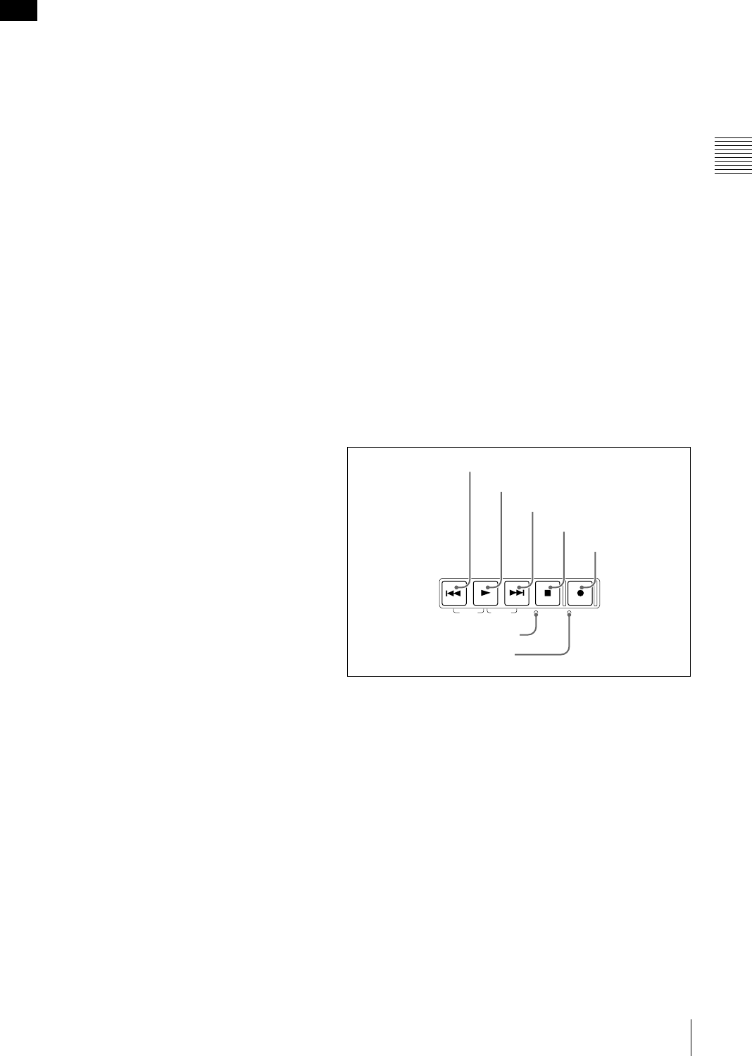
5Recording and playback control section
aPREV (previous) button
Press this button, turning it on, to show the first frame of
the current clip. While the first frame of a clip is shown,
pressing this button jumps to the beginning of the previous
clip. 1) This button is also used together with other buttons
for the following operations.
Reverse direction high-speed search: Hold down the
PLAY button, and press this button. A high-speed
search in the reverse direction is carried out.
Displaying the first frame of the first clip: Hold down
the SHIFT button, and press this button.
1) When setup menu item 153 FIND MODE is set to “clip & rec start mark”,
this button jumps to the frame where the previous Rec Start essence mark
is set and displays the video of that frame.
Note
TOP F REV F FWD END STANDBY REC INHI
PREV NEXTPLAY STOP REC
1PREV button
2PLAY button
3NEXT button
4STOP button
5REC button
6STANDBY indicator
7REC INHI indicator

22 Front Panel
Chapter 2 Names and Functions of Parts
bPLAY button
To start playback, press this button, turning it on.
When pressed during recording, stops recording and enters
stop mode. If you do not want to stop recording when this
button is pressed, set setup menu item 145 MODE KEY
ENABLE DURING RECORDING to “stop”.
cNEXT button
Press this button, turning it on, to jump to the next clip, and
show the first frame. 1) This button is also used together
with other buttons for the following operations.
Forward direction high-speed search: Hold down the
PLAY button, and press this button. A high-speed
search in the forward direction is carried out.
Displaying the last frame of the last clip: Hold down the
SHIFT button, and press this button.
1) When setup menu item 153 FIND MODE is set to “clip & rec start mark”,
this button jumps to the frame where the next Rec Start essence mark is set
and displays the video of that frame.
dSTOP button
To stop recording or playback, press this button, turning it
on. The frame at the stop point appears.
The unit enters standby off mode when you press this
button with the SHIFT button held down. It returns from
standby off mode to the original state when you press this
button again with the SHIFT button held down. (The lit or
unlit status of the STOP button does not change.)
This button flashes when setup menu item 105
REFERENCE SYSTEM ALARM is set to “on” and the
correct reference video input signal (as specified by OUT
REF on page P6 REF of the function menu) is not being
input.
This unit can automatically enter standby off mode
whenever a specified time elapses in disc stop mode. For
details, see the description of setup menu item 501 STILL
TIMER (page 132).
eREC (record) button
To start recording, hold down this button, and press the
PLAY button. The recording takes place on an unrecorded
part of the disc.
To stop recording, press the STOP button.
To monitor in E-E mode
You can press this button from stop mode to monitor input
signals in E-E mode. The button lights when pressed. Press
the STOP button to return to the original video.
You can also press this button during playback and
searches. E-E mode playback continues for as long as the
button is held down.
fSTANDBY indicator
Lights when the unit is in standby mode (STOP button and,
STANDBY indicator lit).
After a certain time passes in a disc stop mode, the unit
automatically enters standby off mode and the indicator
goes off.
You can specify the time until the unit enters standby off
mode. For details, see the description of setup menu item
501 STILL TIMER (page 132).
gREC INHI (recording inhibit) indicator
This lights in the following cases.
• When a disc with recording inhibited is loaded.
• When REC INH on the HOME page of the function
menu is set to “ON”.
• The format of the recorded part of the disc does not
match the system frequency settings of the unit.
Note
23
Front Panel
Chapter 2 Names and Functions of Parts
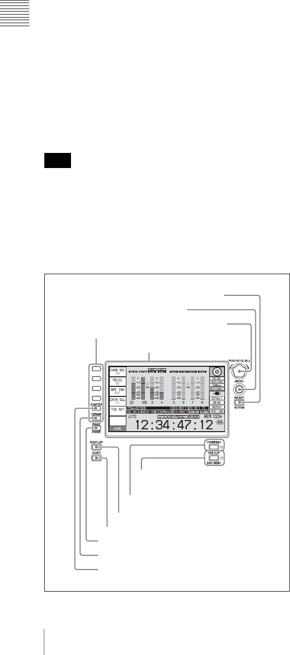
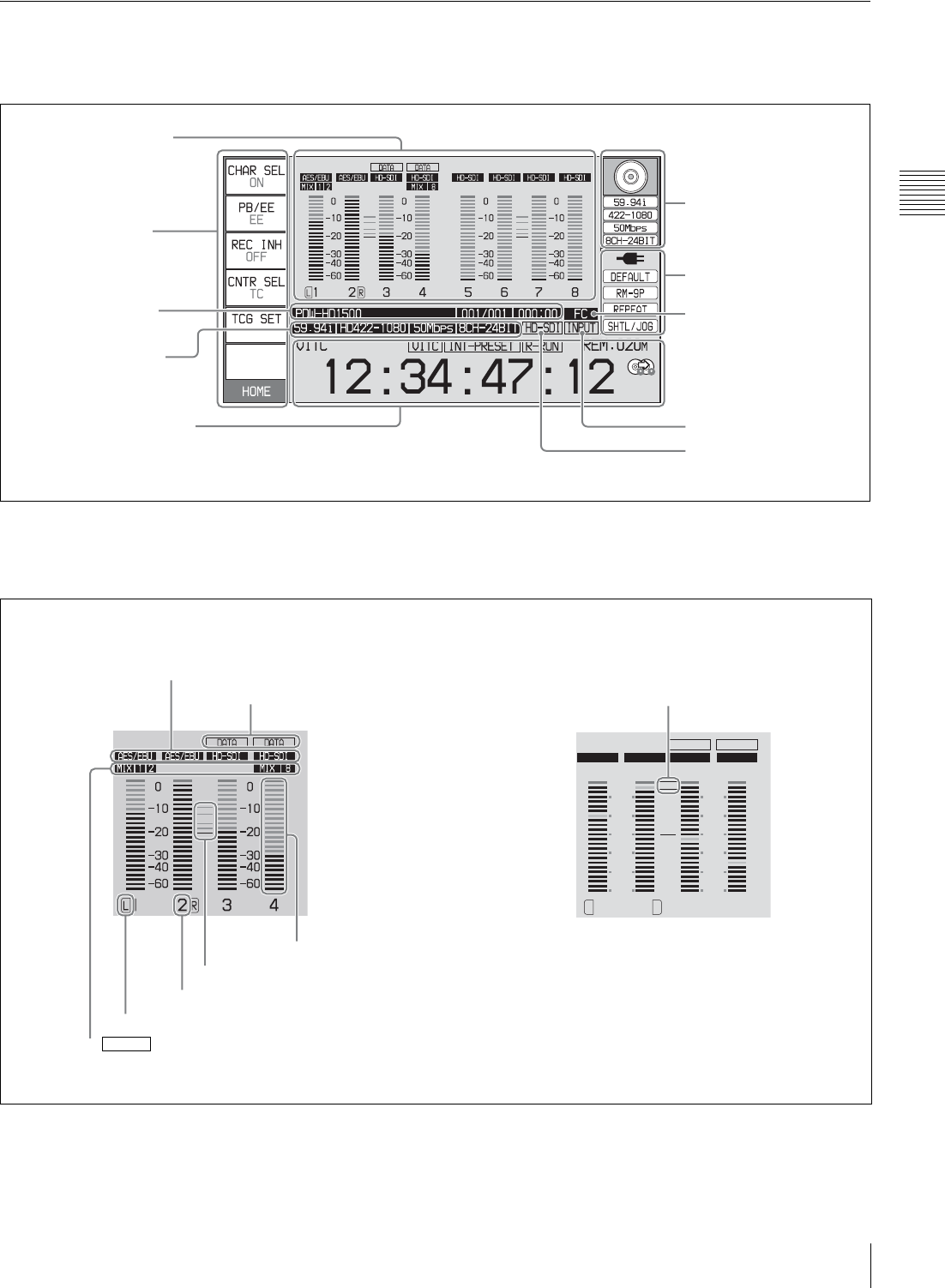
Display window
Basic operation display
aAudio input display/Audio level meters
Displays information about audio. There are two display
modes for the audio level meter: FULL mode and FINE
mode, which can be switched over using AU METER on
page P4 AUDIO of the function menu.
A Input signal display: Displays the audio input signal.
1Audio input display/
Audio level meters a)
2Function menu
3Clip information
4Recording format
5Time data display area
6Disc information
7System information
9Reference signal
8Format conversion
q; Video input display
a) The mixing display appears only on the PDW-F1600
(see the following figure).
2
1
0
-1
-2
2
1
0
-1
-2
1 2 3 4
LR
AES/EBU AES/EBU HD-SDI HD-SDI
DATA DATA
FINE
AInput signal display
BData indication
EAudio channel
FReference level
GLevel bar
DMonitor channel
HMeter display mode
Meter display mode: FULL Meter display mode: FINE
C Mixing
F1600
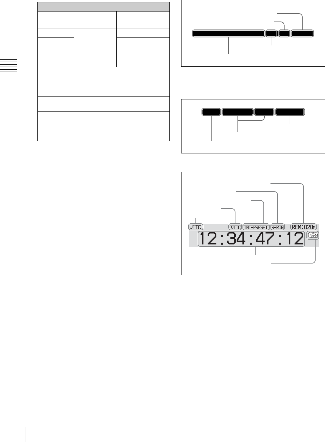
24 Front Panel
Chapter 2 Names and Functions of Parts
.
B Data indication: Appears when the input signals are
non-audio signals.
C Mixing: Displays the input channels used for
audio mixing. (These channels are selected with setup
menu item 819 AUDIO INPUT ARRANGE.)
D Monitor channel: Displays the audio monitoring
channels set with MONITR L and MONITR R on
page P2 AUDIO of the function menu (see page 49).
E Audio channel: Displays the audio channels.
Also indicates preset or variable mode by its color
(see page 18).
White: Preset mode
Green: Variable mode
F Reference level: Displays the reference level for
recording as set in the maintenance menu.
G Level bars: Display the audio recording or playback
levels of channels 1 to 8. The OVER indicators light
when the audio level exceeds 0 dB.
H Meter display mode: Displays the audio level meter
display mode selected with AU METER on page P4
AUDIO of the function menu (see page 50).
bFunction menu
Use the PAGE/HOME button to display this menu, and to
switch between the pages (HOME, P1 to P7, (P8) 1),
(HOME2) 1) ) of the menu. Each page has three to six
setting items. Press the corresponding button to change a
setting.
1) If a menu item is assigned using maintenance menu item M38: F-KEY
CONFIG
For details, see page 48 “Basic Operations of the
Function Menu” in Chapter 3.
cClip information
Displays clip information.
dRecording format
Displays the system frequency and the video and audio
formats.
eTime data display area
A Remaining disc recording capacity: Displays the
amount of recording capacity remaining on the disc.
B Rec Run/Free Run: Displays the timecode run mode.
The run mode is set with RUN MODE on page P5 TC
of the function menu (see page 51).
C Timecode generator mode: Displays the timecode
source and generation method (preset or regenerate).
These are set with PRST/RGN and TCG on page P5
TC of the function menu (see page 51).
D VITC: Lights in the following cases.
• When VITC is read in playback mode. (This has no
relations to the display in the time data display
area.)
• When VITC recording is possible.
E Time data type: Displays the type of time data
displayed in the time data display area. The type of
time data is selected with CNTR SEL on the HOME
page of the function menu (see page 48).
Display Input signal
ANA-1 Analog audio
signal Channel 1, 3
ANA-2 Channel 2, 4
MIC-1 Input signal from
the microphone
connected to
ANALOG
AUDIO INPUT
connector
Channel 1, 3
MIC-2 Channel 2, 4
AES/EBU AES/EBU format digital audio signal
(flashes when there is no input signal)
HD-SDI HDSDI audio signal (flashes when
there is no input signal)
SD-SDI SDSDI audio signal (flashes when
there is no input signal)
SG Test signal from the internal signal
generator
No indication Undefined audio signal, or no audio
input
F1600
PDW-HD1500 001/001 000:00
All remaining clips or clip list playback time
Total number of clips recorded on disc
Clip name
Number of current clip
8CH-24BIT
59.94i HD422-1080 50Mbps
System frequency
Video format
Audio format
A Remaining disc recording capacity
B Rec Run/Free Run
C Timecode generator mode
D VITC
E Time data type
F Time data
G Recording mode indication
25
Front Panel
Chapter 2 Names and Functions of Parts
F Time data: Normally displays timecode or VITC,
according to the selection made with TCR on page P5
TC of the function menu.
G Recording mode indication: This appears when setup
menu item 150 REC MODE is set to “disc exchange
cache” or “clip continuous rec” (see page 130).
See page 56 for more information about the disc
exchange cache function.
See page 57 for more information about the Clip
Continuous Rec function.
fDisc information
A Disc loaded indication/usable format: When a disc is
loaded in this unit, a disc loaded indication appears.
When no disc is loaded, the usable formats are
displayed.
The background color of the disc loaded mark
indicates one of the following disc states.
Blue: Disc capable of recording and playback.
Yellow: Disc capable of playback only.
Red: Disc incapable of recording and playback.
Even if the background is blue, recording is not
possible in the following cases.
• When a disc with recording inhibited is loaded.
• When REC INH on the HOME page of the function
menu is set to “ON”.
The usable formats displayed when no disc is loaded
in this unit are as follows.
a) HD420LP supports playback only.
When the PDBK-S1500 option is installed
a) HD420LP supports playback only.
B System frequency: Displays the system frequency of
the clips recorded on the disc.
C Video format: Displays the video format and bitrate of
the clips recorded on the disc.
D Audio format: Displays the audio format of the clips
recorded on the disc.
gSystem information
A Power status: Displays the status of the power supply
to the unit.
B Menu setting status: Displays the current setting
status of setup menu.
Display Type of time data
TC Timecode
COUNTER Elapsed recording/playback time
UB User bits
VITC VITC
VIUB VIUB
TCG Timecode generator value
UBG User bits generator value
Note
59.94i
422-1080
50Mbps
8CH-24BIT
ADisc loaded indication/usable
format
BSystem frequency
CClip playback format
DAudio format
Display Usable format
HD422: HD422
HD420: HD420HQ/HD420SP/HD420LP a)
Display Usable format
HD422: HD422
HD420: HD420HQ/HD420SP/HD420LP a)
IMX: MPEG IMX 50Mbps/40Mbps/
30Mbps
DVCAM: DVCAM
Display Power status
AC power
Battery
Battery almost exhausted: Flashes at 1 Hz
Battery exhausted: Flashes at 4 Hz
AC power (power-saving mode)
Battery (power-saving mode)
Battery (power-saving mode/low)
DEFAULT
RM-9P
REPEAT
SHTL/JOG
APower status
BMenu setting status
CRemote interface
DClip playback mode
EJog/shuttle dial mode
26 Front Panel
Chapter 2 Names and Functions of Parts
C Remote interface: When the remote control switch is
set to REMOTE, displays the name of the interface
selected with setup menu item 214 REMOTE
INTERFACE.
D Clip playback mode: The clip playback mode appears
as follows, according to the settings of setup menu
items 142 REPEAT MODE and 154 SINGLE CLIP
PLAY MODE.
E Jog/shuttle dial mode: Appears when the unit is in
shuttle, jog, or variable mode.
hFormat conversion
This displays the status of 1080/720 format conversion.
: Format conversion is not being performed.
: Format conversion is being performed.
See page 63 for more information about 1080/720 cross
convert function.
iReference signal
This displays the type of reference signal to which this unit
is synchronizing.
When there is no display, the unit is synchronizing to the
internal reference signal.
INPUT: Input video
HD REF: HD-format reference signal
SD REF: SD-format reference signal
The HD REF or SD REF display flashes when the video
input signal is not synchronized to the reference signal, and
when the signals are synchronized but their phases do not
match.
jVideo input display
This displays the currently selected video input signal.
HDSDI: HDSDI video input
SDSDI: SDSDI video input
i.LINK: i.LINK TS (HDV) input 1)
SG: Test video signal from the internal signal generator
1) When the PDBK-201 option board is installed
The display blinks when there is no video input signal, and
when the video input signal does not match the system
frequency of this unit.
The video signal input is selected with V INPUT on page
P1 VIDEO of the function menu (see page 49).
Video monitor display
When you press the DISPLAY button, the display window
changes to the video monitor display.
A Audio level meters: LEVEL MT on page P2 AUDIO
of the function menu decides whether the meter is to
be displayed and on which side, left or right, it is
displayed in the display window.
B Superimposed information: Appears when CHAR
SEL on the HOME page of the function menu is set to
“ON” or “LCD”.
Display Description
BANK1 The current menu settings are the same
as the settings in menu bank 1.
BANK2 The current menu settings are the same
as the settings in menu bank 2.
BANK3 The current menu settings are the same
as the settings in menu bank 3.
DEFAULT The current menu settings are the same
as the factory defaults.
No display The current menu settings are different
from all of the above.
Display Setup menu setting Description
Item 142 Item 154
REPEAT play off Repeat playback
mode: Perform
repeat playback of
all clips on the disc.
SINGLE off on Single clip playback
mode: Play the
currently selected
clip once.
SNGL
RPT play on Single clip repeat
playback mode:
Play the currently
selected clip
repeatedly.
No
display off off Continuous
playback mode:
Perform continuous
playback of all clips
on the disc, playing
each clip once.
FC
Note
Note
0
-10
-20
-30
-60
-40
1 2
0
-10
-20
DC-SQ
-30
-60
-40
3 4
TCR.00:45.39.18*
JOG STILL
AAudio level meters
CRecording mode indication
EConverter display
DLow battery warning
BSuperimposed information

27
Front Panel
Chapter 2 Names and Functions of Parts
C Recording mode indication: This appears when setup
menu item 150 REC MODE is set to “disc exchange
cache” or “clip continuous rec” (see page 130).
See page 56 for more information about the disc
exchange cache function.
See page 57 for more information about the Clip
Continuous Rec function.
D Low battery warning: Appears and flashes during
operation with a battery pack when the battery power
is almost exhausted.
E Converter display: Displays the current down- or up-
converter mode, depending on the state of the unit.
The current down-converter (DC) mode appears
when HD video is being input and when an HD disc
is being played. The current up-converter (UC) mode
appears when SD video is being input and when an
SD disc is being played.1)
The current modes are those selected with setup menu
items 930 DOWN CONVERTER MODE (DC) and
950 UP CONVERTER MODE 1).
1)When the PDBK-S1500 option is installed.
DC-EC: Down-converter edge-crop mode
DC-LB: Down-converter letter box mode
DC-SQ: Down-converter squeeze mode
UC-EC: Up-converter edge-crop mode
UC-LB: Up-converter letter box mode
UC-SQ: Up-converter squeeze mode
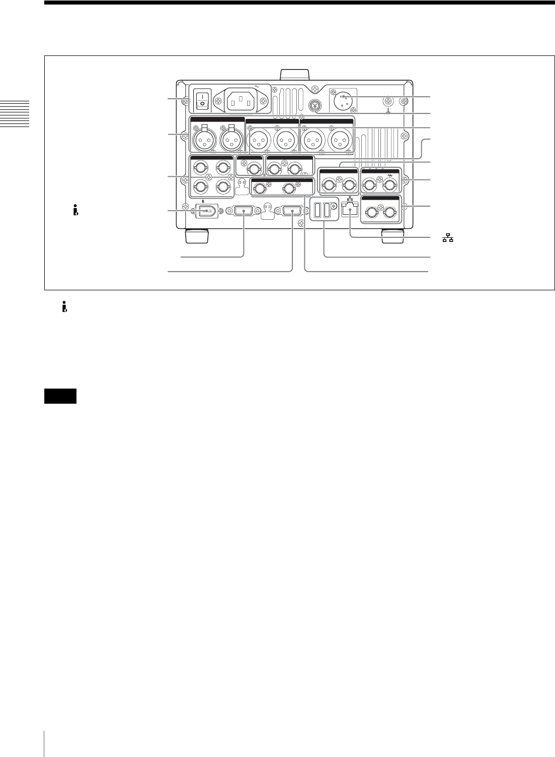
28 Rear Panel
Chapter 2 Names and Functions of Parts
Rear Panel
a (i.LINK) S400 connector (6-pin, IEEE1394
compliant)
Connect a computer or other device, using an i.LINK
cable.
When the PDBK-201 option board is installed, i.LINK TS
(HDV) signals can be input and output via this connector.
• When this unit is connected to a device with a 6-pin
i.LINK connector by an i.LINK cable, before
unplugging the i.LINK cable, first power off the device
and disconnect the power plug from the outlet. If the
i.LINK cable is unplugged with the device power plug
still connected, a current from an excessive voltage (8 to
40 V) output from the i.LINK connector of the device
flows into this unit. This may cause a failure of the unit.
• When connecting this unit to a device with a 6-pin
i.LINK connector, connect to the 6-pin i.LINK
connector of the other device first.
bVIDEO CONTROL connector (D-sub-9-pin)
Connect an HKDV-900 video control unit.
See page 174 for correspondence between setting items of
HKDV-900 and setup menu of this unit.
cREMOTE(9P) (remote control 9-pin) connector
(D-sub 9-pin)
To control this unit from a controller or VTR supporting
the RS-422A Sony 9-pin VTR protocol, connect the device
to this connector.
dDC IN 12V connector (XLR 4-pin, male)
Connect to a DC power source of 12 V.
When using the BKP-L551 Battery Adaptor to mount a
battery pack, connect the power cable of the BKP-L551.
For details, see “Supplying power” on page 32.
eREMOTE connector (4-pin)
Supplies power to the RM-280 Editing Controller.
fSD/HDSDI INPUT (SDSDI/HDSDI signal input)
connector (BNC type)
This inputs an SDSDI or HDSDI format video/audio
signal.
gHDSDI OUTPUT 1, 2 (SUPER) (HDSDI signal
output 1, 2 (superimpose)) connectors (BNC type)
These output HDSDI format video/audio signals.
When editing with two PDW-HD1500 units, connect a
cable between these connectors on the player unit and the
SD/HDSDI INPUT connector on the recorder unit.
You can superimpose timecodes, menu settings, error
messages, or other information on the output of the HDSDI
OUTPUT 2 (SUPER) connector with the setting for
CHAR SEL on the HOME page of the function menu or
with the setting for setup menu item 028 HD
CHARACTER. You can always disable to superimpose
the data independent of the setting for CHAR SEL with the
setting for setup menu item 028.
See “Basic Operations of the Function Menu” (page 48)
for more information about the CHAR SEL settings.
POWER
REMOTE(9P)
MAINTENANCE
VIDEO CONTROL
DC IN 12V=
AC IN
REMOTE
ANALOG AUDIO INPUT
SDSDI OUTPUT
ANALOG AUDIO OUTPUT
12
12
(SUPER)
12
(SUPER)
12
AUDIO MONITOR
RL
1/2 3/4IN
1/2 3/4
OUT
DIGITAL AUDIO (AES/EBU) SD/HDSDI INPUT HDSDI OUTPUT
12
(SUPER)
COMPOSITE OUTPUT IN
REF.VIDEO INPUT
IN OUT
TIME CODE
S400
1Power supply section (see
page 29)
2Analog audio signal input/
output section (see
page 30)
3Digital audio signal input/
output section (see
page 30)
1(i.LINK) S400 connector
2VIDEO CONTROL connector
3REMOTE(9P) connector
4DC IN 12V connector
5REMOTE connector
7HDSDI OUTPUT 1, 2
(SUPER) connectors
8COMPOSITE OUTPUT1, 2
(SUPER) connectors
9REF.VIDEO INPUT
connectors
4Timecode input/output
section (see page 30)
qa MAINTENANCE connectors
qs SDSDI OUTPUT1, 2
(SUPER) connectors
0(network) connector
6SD/HDSDI INPUT connector
Notes
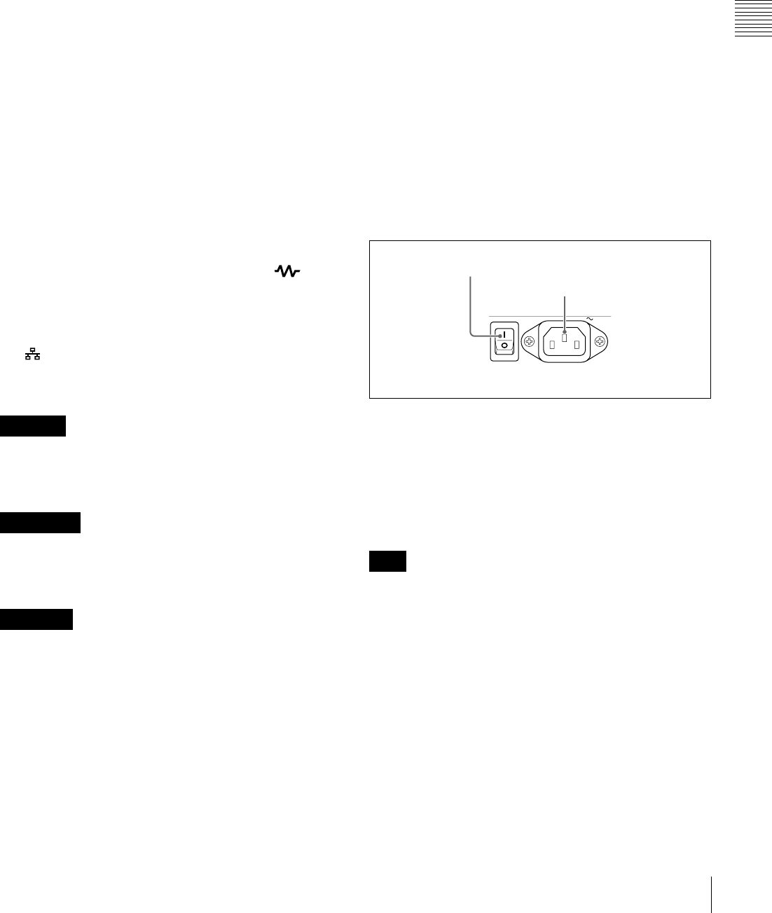
29
Rear Panel
Chapter 2 Names and Functions of Parts
See page 124 for more information about the setup menu
item 028 HD CHARACTER.
To treat the input and output signals of these connectors as
non-audio signals, set the maintenance menu item M37:
AUDIO CONFIG >M372: NON-AUDIO INPUT
(recording) (see page 144) and setup menu item 823 NON-
AUDIO FLAG PB (playback).
hCOMPOSITE OUTPUT 1, 2 (SUPER) (analog
composite video output 1, 2 (superimpose))
connectors (BNC type)
Output analog composite video signals. You can
superimpose timecodes, menu settings, or error messages
on the output of the 2 (SUPER) connector when CHAR
SEL on the HOME page of the function menu is set to ON.
See “Basic Operations of the Function Menu” on page 48
for more information about the CHAR SEL setting.
iREF.VIDEO INPUT (reference video signal input)
connectors (BNC type)
The two connectors form a loop-through connection; when
a reference video signal is input to the left connector, the
same signal is input from the right connector ( ) to a
connected device. When no connection is made to the right
connector, the left connector is automatically terminated
with an impedance of 75 ohms.
j (network) connector (RJ-45 type)
This is a 10BASE-T/100BASE-TX/1000BASE-T
connector for network connection.
For safety, do not connect the connector for peripheral
device wiring that might have excessive voltage to this
port. Follow the instructions for this port.
Par mesure de sécurité, ne raccordez pas le connecteur
pour le câblage de périphériques pouvant avoir une tension
excessive à ce port. Suivez les instructions pour ce port.
Aus Sicherheitsgründen nicht mit einem Peripheriegerät-
Anschluss verbinden, der zu starke Spannung für diese
Buchse haben könnte. Folgen Sie den Anweisungen für
diese Buchse.
kMAINTENANCE connectors
These are the USB connectors for maintenance.
Connect a Windows USB keyboard or mouse (see
page 81), or a USB flash drive to access planning metadata
stored on the drive (see page 92).
lSDSDI OUTPUT 1, 2 (SUPER) (SDI signal outputs
1, 2 (superimpose)) connectors (BNC type)
These output SDSDI format video/audio signals.
When the unit is shipped from the factory, audio signal
output is eight channels with no switching, and RP188
timecode output is set to on. You can change these settings
with setup menu item 828 SDI AUDIO OUTPUT
SELECT and setup menu item 920 SD-SDI H-ANC
CONTROL.
The output from the 2 (SUPER) connector can have
timecode, menu settings, alarm messages, and other text
information superimposed. To turn superimposition off,
set CHAR SEL on the HOME page of the function menu
to “OFF”.
See “Items in the extended menu” (page 129) for more
information.
See “Basic Operations of the Function Menu” (page 48)
for more information.
1Power supply section
aPOWER (main power) switch
Press the : side to power on the unit. Press the a side to
power off.
When using the unit, normally leave the POWER switch in
the : (on) position, and use the on/standby button on the
front panel to switch the unit between the operating state
and standby state.
Before turning the main power off, always check to be sure
that the unit is in the standby state, and then press the main
power switch to the a side.
b-AC IN connector
Connect to an AC power supply with the power cord (not
supplied).
CAUTION
ATTENTION
ACHTUNG
Note
POWER AC IN
1POWER switch
2- AC IN connector
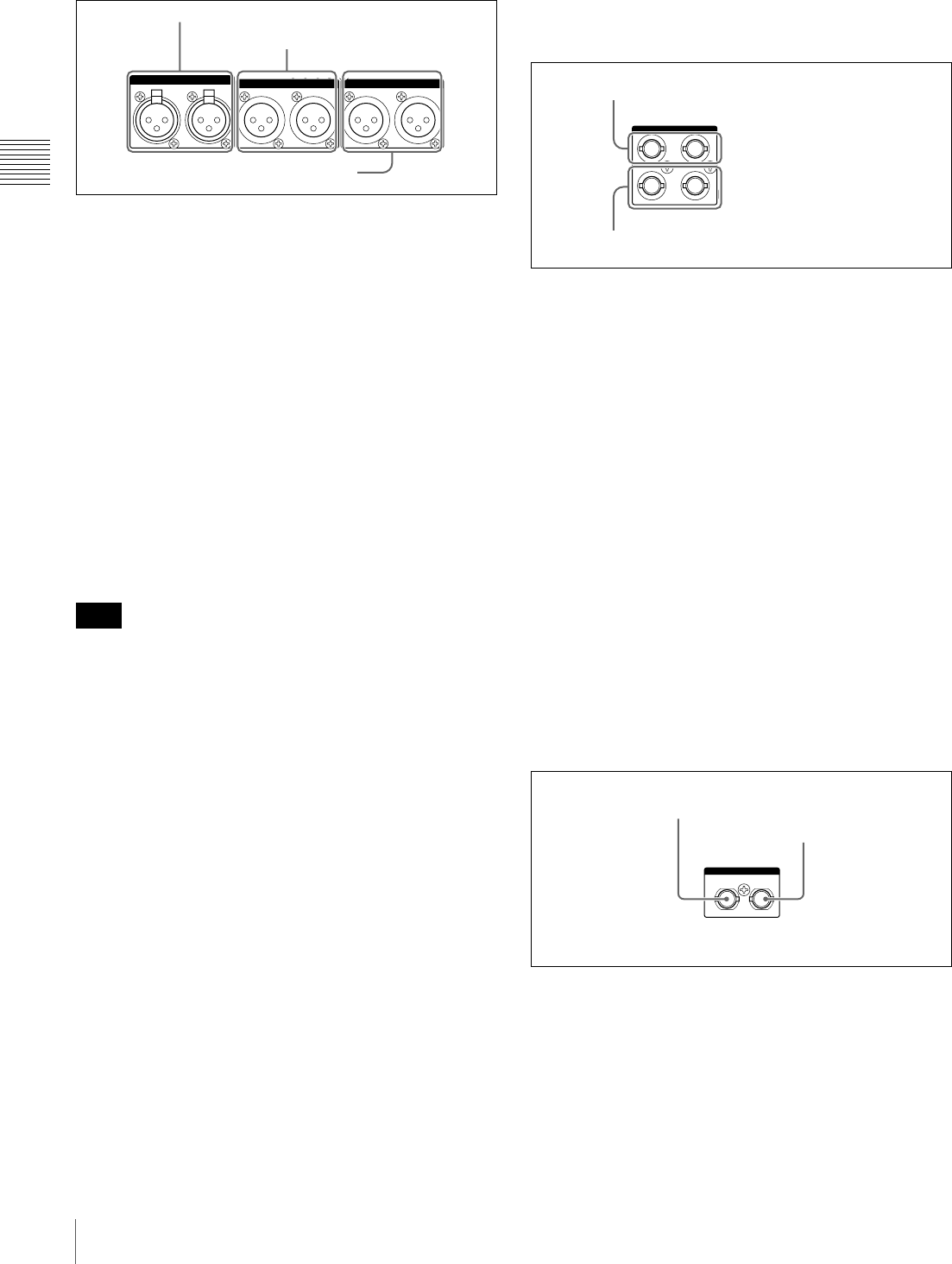
30 Rear Panel
Chapter 2 Names and Functions of Parts
2Analog audio signal input/output section
aANALOG AUDIO INPUT 1, 2 connectors (XLR 3-
pin, female)
These input analog audio signals.
With A1 INPUT or A2 INPUT on page P2 AUDIO, and
A3 INPUT or A4 INPUT on page P3 AUDIO of the
function menu (see page 50), you can select whether the
signal input to connector 1 is assigned to audio channel 1or
3, and whether the signal input to connector 2 is assigned
to audio channel 2 or 4.
You can set the reference input level with the maintenance
menu item M37: AUDIO CONFIG (see page 144).
(Factory default setting: +4 dB)
Microphone settings
If you have connected a microphone to this unit, you can
set input level, AGC, and limiter values for the
microphone with setup menu items 834, 839, 840, and 841
(see page 140).
An unpleasant sound may be output if you have connected
a microphone to the ANALOG AUDIO INPUT 1 or 2
connector and power the microphone on with the input
level too high. Check the input level setting before
connecting a microphone.
bANALOG AUDIO OUTPUT 1, 2 connectors (XLR
3-pin, male)
These output analog audio signals.
When the unit is shipped from the factory, the 1 connector
is set to audio channel 1, and the 2 connector is set to audio
channel 2. You can change these settings with setup menu
item 824 ANALOG LINE OUTPUT SELECT (see
page 139).
You can set the output level with the maintenance menu
item M37: AUDIO CONFIG (see page 144). (Factory
default setting: +4 dB)
Non-audio signals are muted.
cAUDIO MONITOR R, L connectors (XLR 3-pin,
male)
This outputs an audio signal for monitoring.
The monitored channel is selected with MONITR L and
MONITR R on page P2 AUDIO of the function menu.
See “Basic Operations of the Function Menu” (page 48)
for more information.
3Digital audio signal input/output section
aDIGITAL AUDIO (AES/EBU) IN (digital audio
input) 1/2, 3/4 connectors (BNC type)
These input AES/EBU format digital audio signals. The
left connector (1/2) corresponds to audio channels 1 and 2,
and the right connector (3/4) corresponds to audio
channels 3 and 4.
bDIGITAL AUDIO (AES/EBU) OUT (digital audio
output) 1/2, 3/4 connectors (BNC type)
These output AES/EBU format digital audio signals.
When the unit is shipped from the factory, the 1/2
connector is set to audio channel 1/2, and the 3/4 connector
is set to audio channel 3/4. You can change these settings
with setup menu item 827 AES/EBU AUDIO OUTPUT
SELECT (see page 139).
To treat the input and output signals of these connectors as
non-audio signals, set the maintenance menu item M37:
AUDIO CONFIG >M372: NON-AUDIO INPUT
(recording) (see page 144) and setup menu item 823 NON-
AUDIO FLAG PB (playback).
4Timecode input/output section
aTIME CODE IN connector (BNC type)
This inputs an SMPTE timecode generated by an external
device.
bTIME CODE OUT connector (BNC type)
This outputs the following timecode, depending on the
operating state of this unit.
During playback: Playback timecode
Note
ANALOG AUDIO INPUT ANALOG AUDIO OUTPUT
1212
AUDIO MONITOR
RL
1ANALOG AUDIO INPUT 1, 2 connectors
2ANALOG AUDIO OUTPUT 1, 2
connectors
3AUDIO MONITOR R, L connectors
1/2 3/4IN
1/2 3/4
OUT
DIGITAL AUDIO (AES/EBU)
1DIGITAL AUDIO (AES/EBU) IN 1/2, 3/4
connectors
2DIGITAL AUDIO (AES/EBU) OUT 1/2, 3/4
connectors
IN OUT
TIME CODE
1TIME CODE IN connector
2TIME CODE OUT
connector

31
Rear Panel
Chapter 2 Names and Functions of Parts
During recording: The timecode from the internal
timecode generator or the timecode input to the TIME
CODE IN connector
When setup menu item 611 TC OUTPUT PHASE IN EE
MODE is set to “muting”, no timecode is output.
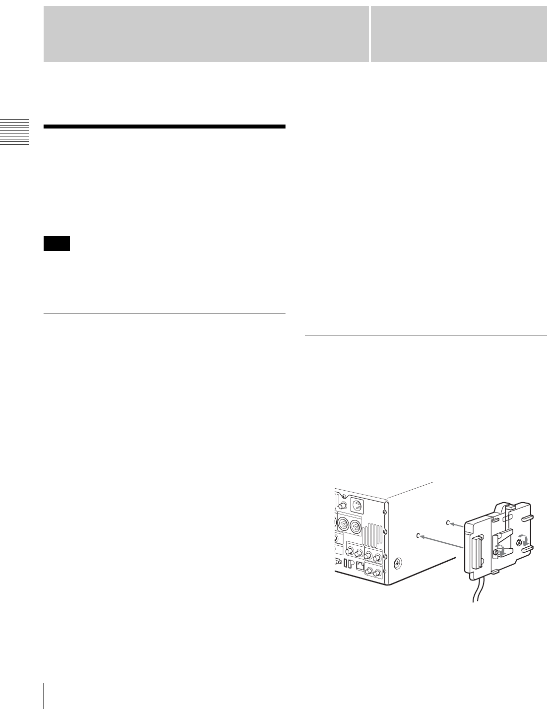
32 Preparing Power Sources
Chapter 3 Preparations
Chapter3
Preparations
Preparing Power Sources
This unit can be powered by AC power, DC power, or a
battery pack.
For safety, use only the Sony battery packs listed below.
Lithium-ion battery pack: BP-L80S, BP-GL95
If you load or remove a battery pack incorrectly, it may fall
and cause bodily injury. Follow the procedures described
below to load or remove them.
Supplying power
AC power supply
Connect the AC IN connector to an AC power source using
the specified AC power cord. To supply AC power to the
unit, set the on/standby button on the front panel to ON and
the POWER switch on the rear panel to = (ON).
DC power supply
Connect the DC IN 12V connector to a DC power source.
To supply DC power to the unit, set the on/standby button
on the front panel to ON and the POWER switch on the
rear panel to OFF. If the POWER switch on the rear panel
is set to = (ON), AC power is supplied.
Battery power supply
Battery packs that can be used with this unit are as follows.
To use battery pack, a BKP-L551 Battery Adaptor and a
BC-L100 Battery Charger are also required.
• BP-L80S
•BP-GL95
Continuous recording time at room temperature
BP-GL95 lithium-ion battery pack: 80 minutes (95
minutes when used in power save mode)
For details on charging battery packs, refer to the
operation manual for the battery charger.
Notes about battery usage
• Before using the batteries, be sure to charge them fully
with the special battery charger. Refer to the operating
instructions for your battery charger for more
information about how to charge the batteries.
• Batteries may not be completely charged if you charge
them immediately after use when they are still warm.
You should wait until the batteries cool before charging
them.
Attaching a battery pack
Attaching and removing of the BP-GL95 Battery Pack is
described below.
The BP-L80S can also be attached and removed in the
same way.
For details on attaching the BKP-L551, refer to the
installation manual for the BKP-L551.
1
Attach the BKP-L551 to the side panel.
2
Align the grooves on the BP-GL95 with the
projections on the BKP-L551.
Note
BKP-L551
33
Initial Setup
Chapter 3 Preparations
3
Slide the BP-GL95 as shown below so that the
connectors on the BP-GL95 and the BKP-L551 are
connected.
4
Connect the DC cable of the BKP-L551 to the DC IN
12V connector.
Removing the battery pack
With the lever pushed in, slide the BP-GL95 out as shown
below.
Checking the remaining battery power
You can use the LEDs on the side panel of the battery to
check the remaining power of the battery.
Initial Setup
This unit is shipped with the area of use, system frequency,
recording format, and current date and time still unset.
Therefore, you need to make initial setup settings before
using the unit. (You cannot use the unit without setting it
up.)
Once the unit has been set up, the settings are retained even
when the unit is powered off.
Use the following procedures.
1
Power the unit on.
The INITIAL SETUP screen appears on the display.
2
Turn the PUSH SET(S.SEL) knob to select the area of
use.
Display UC (for regions outside Japan) or J (for
Japan), and then press the SET function button (F5).
The system frequency screen appears.
3
Turn the PUSH SET(S.SEL) knob to select the system
frequency.
BP-GL95
Lever
REC
NET
REMOTE
LOCAL
VARIABLE KEY INHI
PRE-
SET
ON
OFF
PB
PHONES LEVEL
SHIFT
DISPLAY
HOME
PAG E
EXPAND
CHAPTER
TOP F REV F FWD END STANDBY REC INHI
PREV NEXTPLAY STOP REC THUMBNAIL
RETURN
PUSH SET(S.SEL)
MENU
RESET
MARK2
MARK1
IN OUT
SHTL/JOG
SUB CLIP
DISC MENU
VAR/JOG
EJECT
ACCESS
CH-1
ALL CH
CH-2
CH-3
CH-4
POWER AC IN
1
55,6 2,3,4
RETURN
SET
INIT
INITIAL SETUP
UC/J MODEL
SELECT
NONE
INC/DEC : CTRL.KNOB
CANCEL&PREV : F1(RET)
SET&NEXT : F5(SET)
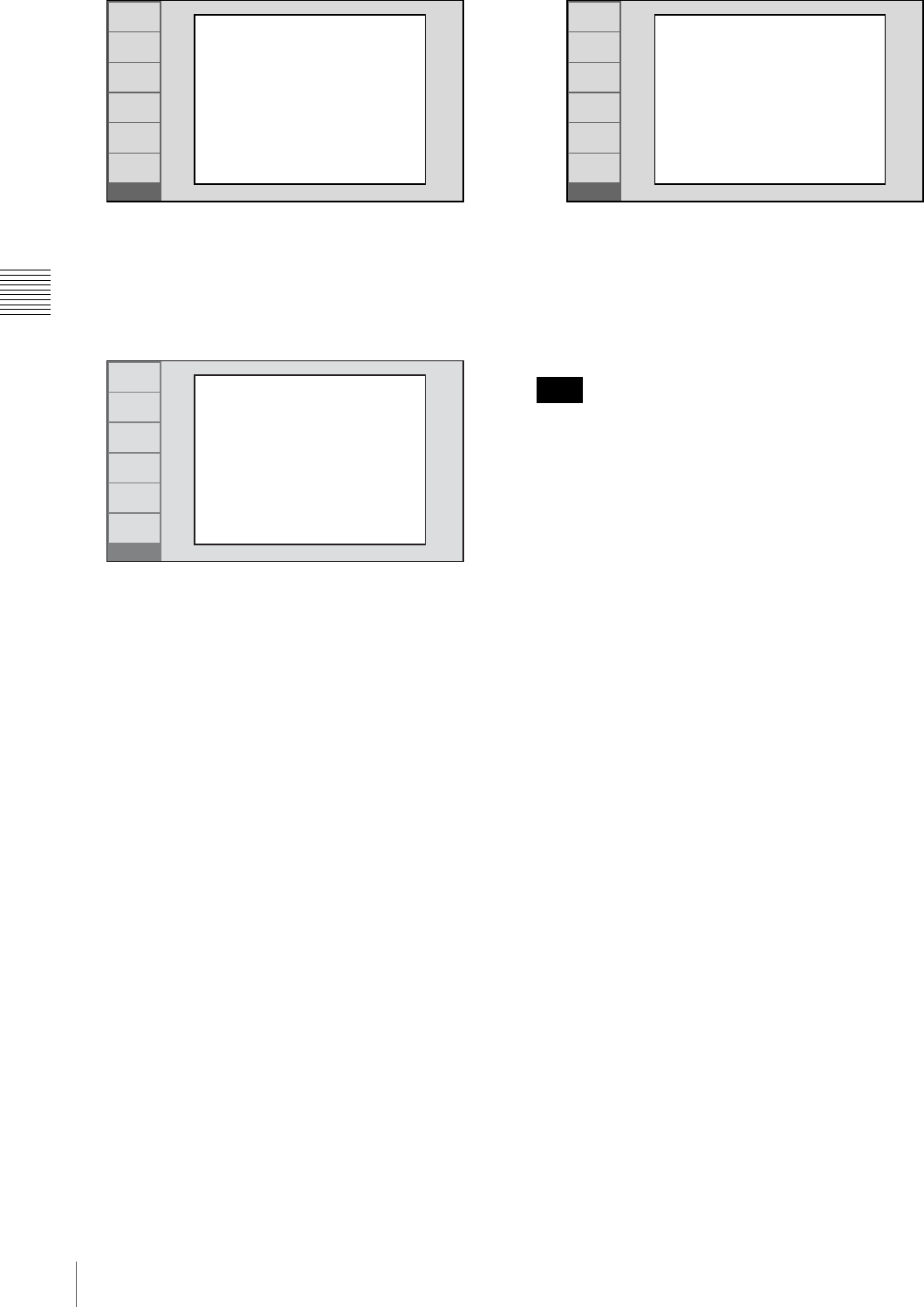
34 Initial Setup
Chapter 3 Preparations
Display the system frequency that you want to use, and
then press the SET function button (F5).
The DATE/TIME PRESET screen appears.
4
In the DATE/TIME PRESET screen, set the current
date and time by setting the following items.
YEAR: Year
MONTH: Month
DAY: Day
TIME: Time
TIME ZONE: Time zone (as a difference in hours
with respect to Coordinated Universal Time
(UTC))
In the setting screen, you can change the value of the
flashing digit.
Press the B/IN or b/OUT button to make the previous
digit or next digit start flashing.
Press the V/MARK1 or v/MARK2 button (or turn the
PUSH SET(S.SEL) knob) to increment or decrement
the value of the flashing digit.
When you have finished making settings, press the
SET function button (F5).
The date, time, and time zone settings are saved, and
the message “NOW SAVING...” appears.
5
If you want to save the settings made up to this point,
press the SET function button (F5) again.
The message “NOW SAVING...” appears again, and
the setting screen disappears. Then the unit powers
itself off and on again.
To return to the original screen without saving
settings
Press the RETURN function button (F1).
The time zone is reset to the factory default when you
execute the maintenance menu item M49: RESET ALL
SETUP. You will need to set it again. The date and time
are not reset.
RETURN
SET
INIT
INITIAL SETUP
SYSTEM FREQUENCY
SELECT
1080/50i
INC/DEC : CTRL.KNOB
CANCEL&PREV : F1(RET)
SET&NEXT : F5(SET)
RETURN
SET
INIT
DATE/TIME PRESET
YEAR 2008
MONTH 11
DAY 19
TIME 16:49:00
TIME ZONE UTC+00:00
INC/DEC : CTRL.KNOB
SHIFT : (P)(p)KEY
CANCEL&PREV : F1(RET)
SET&NEXT : F5(SET)
Note
RETURN
SET
INIT
INITIAL SETUP
Push F5(SAVE) Key!!
CANCEL&PREV : F1(RET)
SAVE&REBOOT : F5(SET)
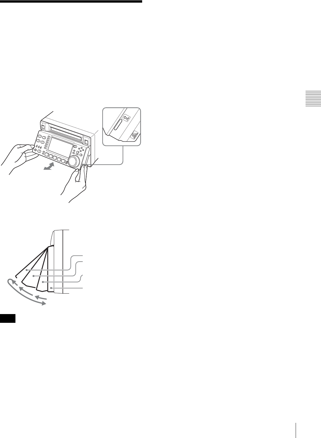
35
Front Panel Tilt Mechanism
Chapter 3 Preparations
Front Panel Tilt
Mechanism
The front panel of this unit has a tilt mechanism that allows
you to pull the front panel out and adjust it to a convenient
angle.
To pull the front panel out
Grasp the holds (small protrusions) on both sides of the
front panel and pull out as indicated by the arrow.
You can fix the angle of the front panel in position 1 (15
degrees) or position 2 (40 degrees).
The angle cannot be fixed if you pull the front panel past
position 2 all the way out to the return position. To fix the
front panel, return it to position 0 and then pull it out to
position 1 or position 2.
To return the front panel to its original
position
Unlock the front panel by pulling it out to the return
position. You can then return it to position 0.
To change the angle of the front panel
To change the angle to position 2 from position 1, pull the
front panel out to position 2.
To change the angle to position 1 from position 2, first
unlock the front panel by pulling it all the way out to the
return position. Then return it to position 0, and pull out
again to position 1.
Note
Return position
Position 2 (40 degrees)
Position 1 (15 degrees)
Position 0
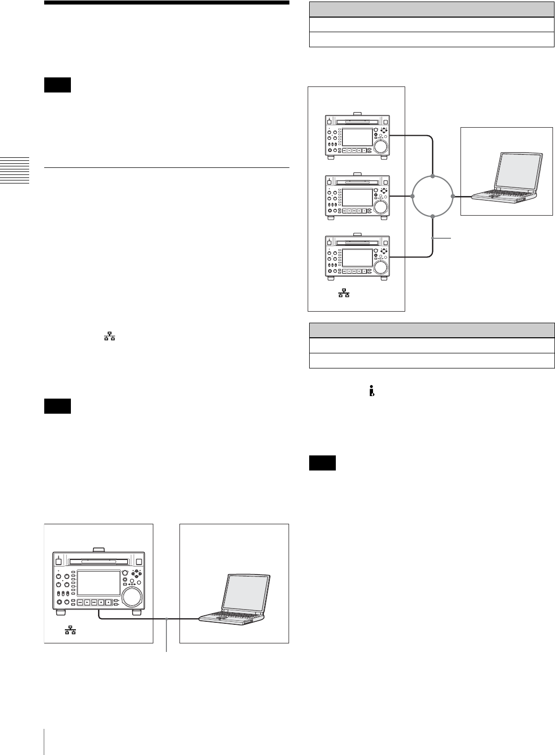
36 Connections and Settings
Chapter 3 Preparations
Connections and
Settings
Production of some of the peripherals and related devices
described in this chapter has been discontinued.
For advice about choosing devices, please contact your
Sony dealer or a Sony sales representative.
Connections for using PDZ-1 Proxy
Browsing Software
You can use the PDZ-1 Proxy Browsing Software on the
supplied XDCAM Application Software CD-ROM to
carry out simple editing with proxy AV data.
For an overview of PDZ-1 and how to install the software,
see “Using PDZ-1 Proxy Browsing Software” on
page 170. For information about how to use the software,
refer to the Help provided in the software.
Using the (network) connector (FTP
connection)
The following shows an example of an FTP (File Transfer
Protocol) connection.
To use PDZ-1 requires the PDW-F1600 or PDW-HD1500
IP address and other network-related settings to be made
beforehand.
For details of the network-related settings, see “To change
network settings” (page 149).
Connecting this unit directly to a laptop computer
Connecting three PDW-F1600 or PDW-HD1500
units to a laptop computer via a LAN
Using the (i.LINK) S400 connector (FAM
connection)
The following shows an example of a FAM (file access
mode) connection.
The PDZ-1 Proxy Browsing Software must be installed in
advance.
The required FAM driver is also installed when you install
the PDZ-1 software.
See “Using PDZ-1 Proxy Browsing Software” (page 170)
for more information about installing the PDZ-1 software.
Some limitations apply to FAM connections. For details,
see “File Operations in File Access Mode (for Windows)”
(page 110).
Note
Note
PDW-F1600 or PDW-
HD1500 (this unit)
To (network) connector
Network cable (not supplied)
Laptop computer
Settings on this unit
Remote control switch: NET (see page 18)
Setup menu item 257 NETWORK ENABLE: net
Settings on all PDW-HD1500
Remote control switch: NET (see page 18)
Setup menu item 257 NETWORK ENABLE: net
Note
LAN
Network cable
(not supplied)
To (network)
connector
Laptop computer
PDW-F1600 or
PDW-HD1500

37
Connections and Settings
Chapter 3 Preparations
Use of a shielded cable is recommended.
Connections for cut editing
The following figure shows a cut editing system
comprising this unit as a player.
When making the connections, also refer to the manuals
provided with the equipment to be connected.
See page 39 for more information about editing control
unit settings.
When using an editing control unit
Using BVE-700/700A
The following figure shows a cut editing system
comprising this unit as a player, an HDW-M2000/M2000P
unit as a recorder, and a BVE-700/700A as an editing
control unit.
i.LINK cable (not supplied)
To S400 connector
Laptop computer
PDW-F1600 or PDW-
HD1500 (this unit)
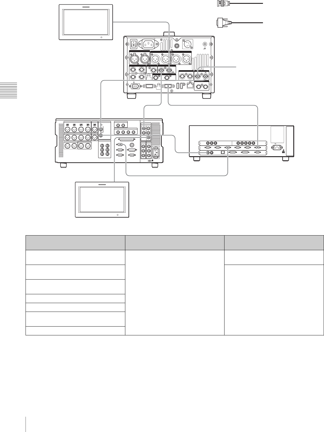
38 Connections and Settings
Chapter 3 Preparations
HDW-M2000 (recorder) settings BVE-700/700A (editing control unit)
setting Settings on this unit
REMOTE 1 (9P) button: Lit SYNCHRONIZE menu:OFF Remote control switch: REMOTE (see
page 18)
REF.VIDEO INPUT connector 75 Ω
termination switch: OFF Setup menu item 214 REMOTE
INTERFACE: 9PIN
Audio selection function switching button
INPUT button: HDSDI
Function menu HOME >F1 (VID. IN): SDI
Function menu page 1 >F1 (TCG): INT
Function menu page 1 >F2 (PR/RGN):
PRESET
Function menu page 1 >F3 (RUN): FREE
75Ω
AC IN
SDI OUT SDI IN
SWER
REF VIDEO IN
MONITOR
OUT VIDEO
OUT2 VIDEO
OUT1
RECORDER
AUX/
PLAYER-3
TITLE
RECORDER
PLAYER-2
PLAYER-1
PANE L
NETWORK
GPI EDL
MIXER
PLAYER-3 PLAYER-2 PLAYER-1
POWER
REMOTE(9P)VIDEO CONTROL
DC IN 12V=
AC IN
REMOTE
ANALOG AUDIO INPUT
SDSDI OUTPUT
ANALOG AUDIO OUTPUT
12
12
(SUPER)
12
(SUPER)
12
AUDIO MONITOR
RL
1/2 3/4IN
1/2 3/4
OUT
DIGITAL AUDIO (AES/EBU) SD/HDSDI INPUT HDSDI OUTPUT
12
(SUPER)
COMPOSITE OUTPUT IN
REF.VIDEO INPUT
IN OUT
TIME CODE
S400
MAINTENANCE
HDSDI
OUTPUT1
HDSDI OUTPUT 2
(SUPER)
HDSDI
INPUT
REMOTE(9P)
REF
VIDEO IN
REMOTE 1-IN(9P)
HDSDI
OUTPUT 3
(SUPER)
REF VIDEO
INPUT
RECORDER
PLAYER-1
REF.VIDEO
INPUT
REF.VIDEO
INPUT
REF VIDEO
INPUT
1
1
1
1
1
2
2
HD video monitor
To HDSDI input connector
1: 75Ω coaxial cable (not supplied)
2: 9-pin remote control cable (not supplied)
PDW-F1600 or
PDW-HD1500
(this unit, player)
Reference video signal
HDW-M2000 (recorder)
To HDSDI input
connector
HD video monitor
BVE-700/700A
(editing control unit)

39
Connections and Settings
Chapter 3 Preparations
Editing Control Unit Settings
When connecting an editing control unit (BVE-700/700A/
2000) to use with this unit, set VTR constants as follows.
a) This is 15 when maintenance menu item M393: AUDIO DSP is set to
“AGC/limiter”.
.
a) When the PDBK-F1500 option is installed.
Using RM-280
The following figure shows a cut editing system
comprising a PDW-HD1500 as a player, a PDW-F1600
unit as a recorder, and an RM-280 as an editing controller.
System
frequency VTR CONSTANT
1 2 345678910 11 12 13 14 15 16
59.94i/
59.94P/
29.97P
A0 97 00 96 07 a) 07 a) 03 80 0A 07 FE 00 80 5A FF 5A
50i/50P/25P A1 97 00 7D 07 a) 07 a) 03 80 0A 07 FE 00 80 4C FF 4B
23.98P A2 97 00 78 07 a) 07 a) 03 80 0A 07 FE 00 80 48 FF 48
F1600
System
frequency VTR CONSTANT
12345678910 11 12 13 14 15 16
59.94i/
59.94P/
29.97P
A0 96 00 96 15 15 03 80 0A 07 FE 00 80 5A FF 5A
50i/50P/25PA196007D151503800A07FE00804CFF4B
23.98P a) A2 96 00 78 15 15 03 80 0A 07 FE 00 80 48 FF 48
HD1500
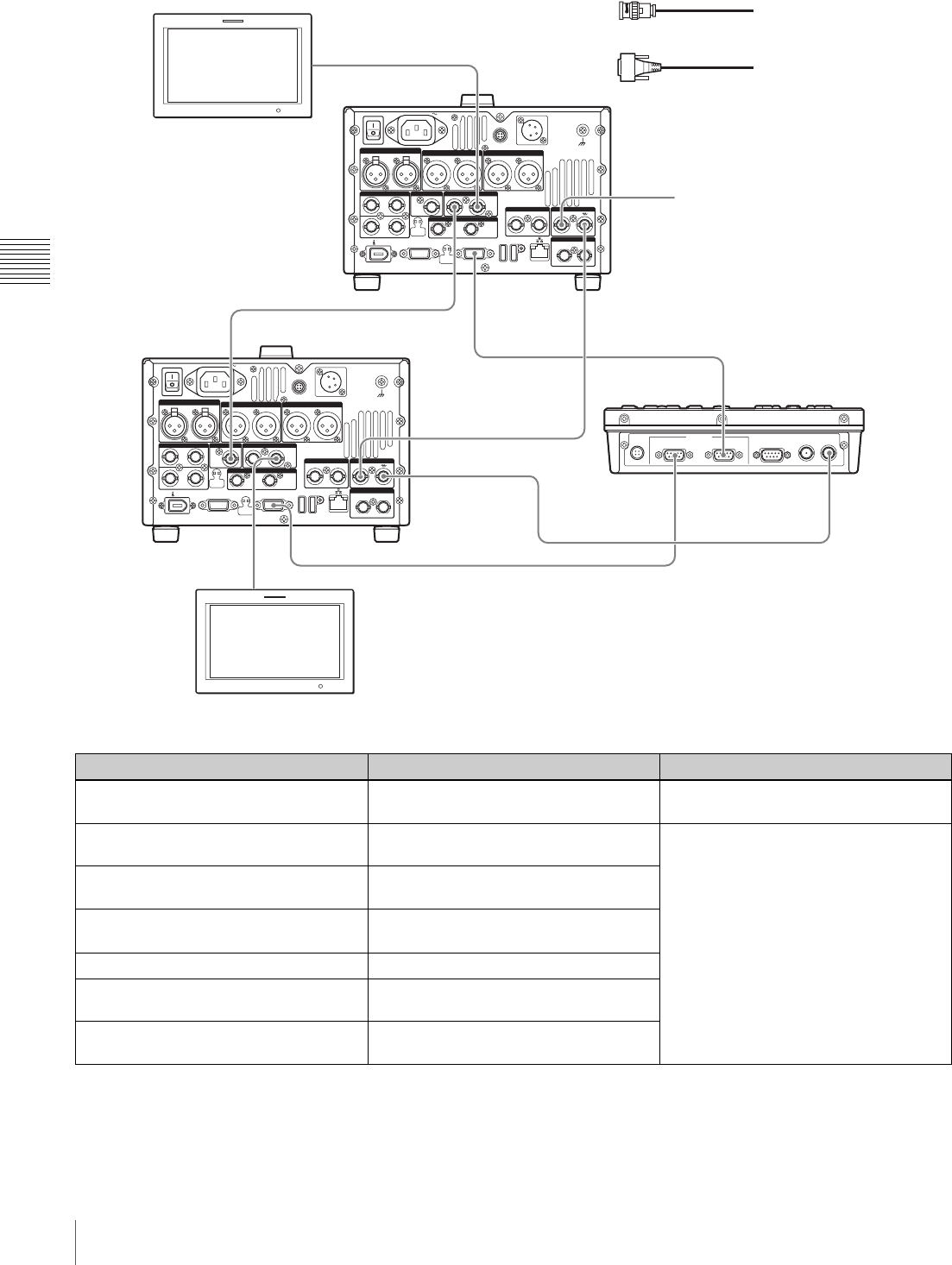
40 Connections and Settings
Chapter 3 Preparations
PDW-F1600 (recorder) settings RM-280 (editing controller) settings PDW-HD1500 (player) settings
Remote control switch: REMOTE EDITOR/REMOTE CONTROL selector
switch: EDITOR Remote control switch: REMOTE (see
page 18)
Setup menu item 214 REMOTE
INTERFACE: 9PIN Setup menu 01 PREROLL: 5s Setup menu item 214 REMOTE
INTERFACE: 9PIN
Function menu page P1 VIDEO >V
INPUT: HD SDI Setup menu 05 SYNC SEL: ON
Function menu pages P2 and P3 AUDIO
>A1 to A8 INPUT: SDI Setup menu 06 SYNC VTR:
RECORDER
Function menu page P5 TC >TCG: INT Setup menu 09 EDIT DLY: –7
Function menu page P5 TC >PRST/
RGN: PRESET Setup menu 10 R ST DLY:AUTO
Function menu page P5 TC >RUN
MODE: FREE RUN Setup menu 11 P ST DLY:AUTO
DC IN
RECORDER (DEVICE 1)PLAYER (DEVICE 2)RS232C
REC TALLY
OUTPUT
REF
IN / OUT
REMOTE (9P)
POWER
REMOTE(9P)VIDEO CONTROL
DC IN 12V=
AC IN
REMOTE
ANALOG AUDIO INPUT
SDSDI OUTPUT
ANALOG AUDIO OUTPUT
12
12
(SUPER)
12
(SUPER)
12
AUDIO MONITOR
RL
1/2 3/4IN
1/2 3/4
OUT
DIGITAL AUDIO (AES/EBU) HDSDI OUTPUT
12
(SUPER)
COMPOSITE OUTPUT
IN
REF.VIDEO INPUT
IN OUT
TIME CODE
S400
MAINTENANCE
SD/HDSDI INPUT
HDSDI
OUTPUT1
HDSDI OUTPUT 2
(SUPER)
SD/HDSDI
INPUT
REMOTE(9P)
REMOTE(9P)
RECORDER(DEVICE1)
REMOTE(9P)
RECORDER(DEVICE2)
REMOTE(9P)
HDSDI
OUTPUT 2
(SUPER)
REF.VIDEO
INPUT
REF IN/OUT
REF.VIDEO
INPUT
REF.VIDEO
INPUT
REF VIDEO
INPUT
1
1
1
1
1
1
2
2
HD video monitor
To HDSDI input connector
1: 75Ω coaxial cable (not supplied)
2: 9-pin remote control cable (not supplied)
PDW-HD1500 (player)
Reference video signal
PDW-F1600
(recorder)
To HDSDI input
connector
RM-280
(editing
controller)
HD video monitor
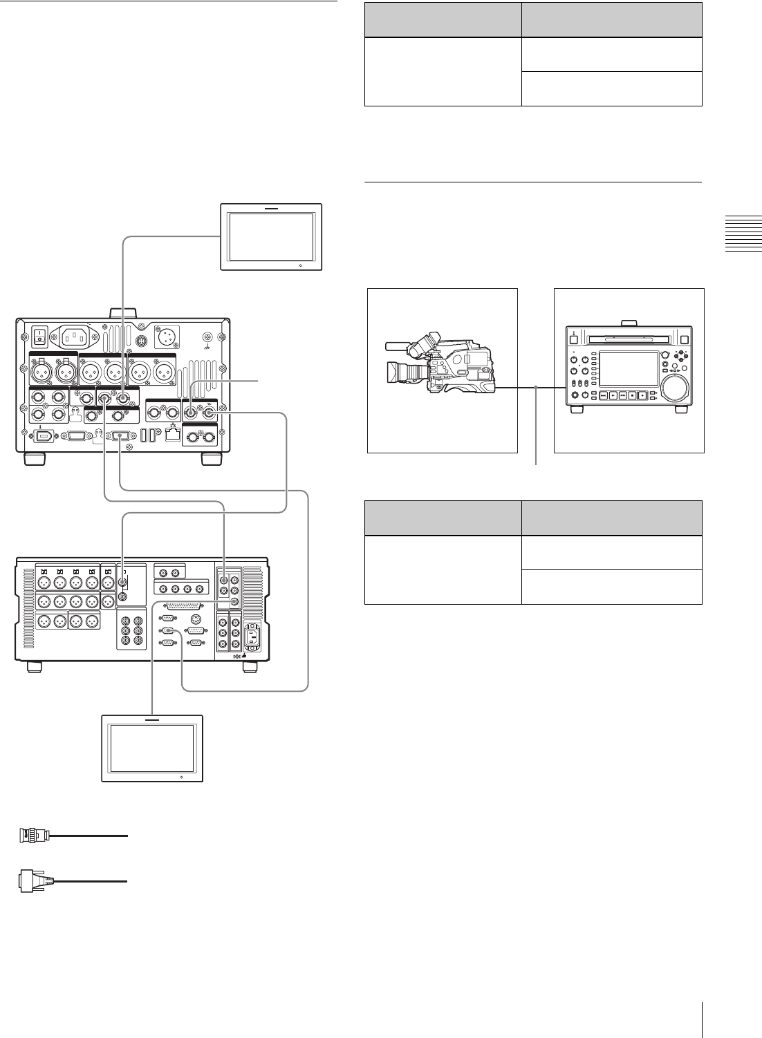
41
Connections and Settings
Chapter 3 Preparations
Using the editing functions of the
recorder (controlling through
REMOTE(9P) connector)
The following figure shows a cut editing system
comprising this unit as a player, and an HDW-M2000/
M2000P unit as a recorder. In this example, video and
audio signals are connected by HDSDI, and control signals
are transferred via the REMOTE(9P) connector.
For details of HDW-M2000/M2000P settings, refer to the
HDW-M2000/M2000P Operation Manual.
Connections for pool coverage
The following figure shows an example of connections for
pool coverage, with the PDW-700 Professional Disc
Camcorder connected.
75Ω
POWER
REMOTE(9P)VIDEO CONTROL
DC IN 12V=
AC IN
REMOTE
ANALOG AUDIO INPUT
SDSDI OUTPUT
ANALOG AUDIO OUTPUT
12
12
(SUPER)
12
(SUPER)
12
AUDIO MONITOR
RL
1/2 3/4IN
1/2 3/4
OUT
DIGITAL AUDIO (AES/EBU) HDSDI OUTPUT
12
(SUPER)
COMPOSITE OUTPUT IN
REF.VIDEO INPUT
IN OUT
TIME CODE
S400
MAINTENANCE
SD/HDSDI INPUT
REF.VIDEO
INPUT
REMOTE 1-OUT(9P)
HDSDI
OUTPUT 3
(SUPER)
REMOTE(9P)
REF.VIDEO
INPUT
REF VIDEO
INPUT HDSDI
INPUT
HDSDI
OUTPUT2
(SUPER)
HDSDI
OUTPUT1
1
1
1
1
1
2
HD video monitor
To HDSDI input connector
PDW-F1600 or PDW-HD1500
(this unit, player)
Reference
video signal
HDW-M2000
(recorder)
To HDSDI
input
connector
1: 75Ω coaxial cable (not supplied)
2: 9-pin remote control cable (not supplied)
HD video monitor
HDW-M2000 (recorder)
setting Settings on this unit
REMOTE 1 (9P) button:
Unlit Remote control switch:
REMOTE (see page 18)
Setup menu item 214
REMOTE INTERFACE: 9PIN
PDW-700 (camcorder)
setting Settings on this unit
HDSDI REMOTE I/F on
page CAM CONFIG 1 of
the MAINTENANCE menu:
other than OFF
Remote control switch:
REMOTE (see page 18)
Setup menu item 214
REMOTE INTERFACE: SDI
75Ω coaxial cable (not supplied)
To SDI OUT 1 connector
PDW-700 PDW-F1600 or PDW-
HD1500 (this unit)
To SD/HDSDI INPUT
connector

42 Synchronization Reference Signals
Chapter 3 Preparations
Synchronization Reference Signals
The synchronization reference signal generator of this unit
synchronizes to a reference signal input to the REF.
VIDEO INPUT connector or to a video input signal.
External synchronization is as follows, depending on the
setting of OUT REF on page P6 REF of the function menu,
and on the type of the selected input signal. Video output
signals are always synchronized to the internal
synchronization signal.
a) Same as when V INPUT on page P1 VIDEO of the function menu is set to
“SG”.
b) FAM and FTP connections always synchronize to the internal
synchronization reference signal, regardless of the setting of OUT REF.
Synchronization reference signals when
you are recording, playing, or editing 720P
signals
When you are recording, playing, or editing 720P signals,
set OUT REF on page P6 REF of the function menu item
to “REF”, and synchronize the internal reference signal
generator of this unit to a reference signal input to the REF.
VIDEO INPUT connector. The following reference
signals may be used.
720/59.94P system: 1080/59.94i tri-level sync signal, 525
black burst signal
720/50P system: 1080/50i tri-level sync signal, 625 black
burst signal
When you connect this unit directly to the video I/O
connectors of the PDW-F1600/HD1500/F800/700, you
can record and dub 720P signals even if you set OUT REF
on page P6 REF of the function menu item to “INPUT”.
Input to SD/HDSDI
INPUT connector a)
Input to REF. VIDEO
INPUT connector Setting of OUT REF on page P6 REF b)
REF INPUT
Yes Yes Synchronize to the signal input to
the REF. VIDEO INPUT connector Synchronize to the signal input to
the SD/HDSDI INPUT connector
Yes No Synchronize to the signal input to the SD/HDSDI INPUT connector
No Yes Synchronize to the signal input to the REF. VIDEO INPUT connector
No No No external synchronization is made
43
Setting System Frequency / Setting Timecode
Chapter 3 Preparations
Setting System
Frequency
This unit can record and play back video at the system
frequencies of 59.94i, 50i, 29.97P, 25P, and 23.98P 1)
(1080) or 59.94P and 50P (720).
1) When the PDBK-F1500 option is installed.
Selecting the system frequency
1
Set setup menu item 013 SYSTEM FREQUENCY
SELECT MENU to “on” and press the PUSH
SET(S.SEL) knob.
The system frequency selection screen appears.
2
Turn the PUSH SET(S.SEL) knob to select the system
frequency to be used.
3
Press the PUSH SET(S.SEL) knob or the SAVE
function button (F5).
The message “Turn off/on POWER!!” appears.
4
After pressing the on/standby button to power off the
unit, power it on again.
Setting Timecode
There are the following four ways of recording timecode:
Internal Preset mode: This records the output of the
internal timecode generator, set beforehand to an
initial value. The following run modes can be
selected.
• Free Run: Timecode advances continually.
• Rec Run: Timecode advances only during
recording.
Internal Regen mode: This records the output of the
internal timecode generator, initialized to timecode
following continuously upon the timecode of the last
frame of the last clip on the disc.
External Regen mode: This records the output of the
internal timecode generator, synchronized to an
external timecode generator. As the external input, the
timecode input to any of the following connectors can
be selected.
• TIME CODE IN connector: LTC
• SD/HDSDI INPUT connector: VITC and LTC
• (i.LINK) S400 connector: TC
External Preset mode: This directly records the input of
an external timecode generator. As the external input,
the timecode input to any of the TIME CODE IN
connector can be selected.
To record timecode after setting an initial
value (Internal Preset)
Proceed as follows with the function menu. For setting the
timecode, set TCG on page P5 TC of the function menu to
INT and PRST/RGN to PRESET.
Setting an initial timecode value
1
Press the CNTR SEL function button on the HOME
page of the function menu, and select TC.
HD1500
RETURN
-
+
SAVE
SETUP
EXIT
SYSTEM FREQUENCY
SELECT
1080/59.94i
If the System Frequency
setting is changed,
Turn power off and on
again.
RETURN
-
+
SAVE
SETUP
EXIT
SYSTEM FREQUENCY
SELECT
1080/50i
Push F5(SAVE) Key!!
Time data display area
Function menu
Function buttons

44 Setting Timecode
Chapter 3 Preparations
2
Press the TCG SET function button (F5).
The first digit of the time data display starts flashing.
3
Press the T or t function button (F1 or F2) to select
a digit to be set.
The selected digit starts flashing.
4
Use the PUSH SET(S.SEL) knob or – or + function
button (F3 or F4) to set the value for the selected digit.
To set the next-most significant digit (10s place)
Turn the PUSH SET(S.SEL) knob while holding down
the SHIFT button.
Repeat steps 3 and 4 to set all digits that should be set.
To set to 00:00:00:00
Press the RESET/RETURN button.
5
Press the SET function button (F5) .
If RUN MODE on page P5 TC is set to FREE RUN,
the timecode starts running.
To cancel a setting
Press the EXIT function button (F6). Any new settings to
that point are canceled, and the setting operation is
terminated.
Setting the timecode to the current time
1
Set RUN MODE on page P5 TC to FREE RUN and
DF/NDF to DF (in 59.94i/59.94P/29.97P mode only).
2
Perform steps 1 to 4 of “Setting an initial timecode
value” to set the timecode to a time slightly ahead of
the current time.
3
Press the SET function button (F5) at the instant when
the current time matches the displayed timecode.
Setting user bits
You can record up to 8 hexadecimal digits of information
(date, time, event number, etc.) on the timecode track.
Select UB by pressing the CNTR SEL function button (F4)
in step 1 of “Setting an initial timecode value” and carry
out steps 2 to 5. Settings are made in hexadecimal (0-9,
A-F).
You can record ID codes in user bits.
To record timecode that follows
sequentially upon the last recorded
timecode (Internal Regen)
You can record timecode so that it is continuous from one
clip to the next on the disc.
Set TCG on page P5 TC of the function menu to INT, and
PRST/RGN to TC or VITC. When this setting is in force,
the unit reads the timecode of the last frame of the last
recorded clip on the disc before starting to record, and
internally generates timecode that follows upon the
recorded timecode.
The frame count mode (for system frequency 59.94i/
59.94P/29.97P only) is set to the same mode as the last
recorded timecode on the disc (drop-frame or non-drop-
frame).
To record with the internal timecode
generator synchronized to external
timecode (External Regen)
Use this method to synchronize the timecode generators of
a number of recorders, to record the playback timecode of
external VTRs, or to record while maintaining
synchronization between the source video and timecode.
Use either of the following procedures according to the
type of external timecode.
Synchronizing with timecode input to the TIME
CODE IN connector
1
Connect the timecode output of an external device to
the TIME CODE IN connector, and input a reference
video signal to the REF. VIDEO INPUT connector.
2
Make the following settings on page P5 TC of the
function menu.
• Set TCG to “EXT”.
• Set PRST/RGN to “TC”.
Synchronizing with embedded LTC input to the
SD/HDSDI INPUT connector
1
Input an HDSDI signal containing embedded LTC to
the SD/HDSDI INPUT connector, and a reference
video signal to the REF. VIDEO INPUT connector.
2
Make the following settings on page P5 TC of the
function menu.
• Set TCG to “SDI”.

45
Superimposed Text Information
Chapter 3 Preparations
• Set PRST/RGN to “TC”.
Executing either of these procedures starts the internal
timecode generator running in synchronization with the
external timecode generator.
Once the internal timecode generator is synchronized with
the external timecode generator, the internal timecode
generator continues to run even if the external timecode
generator connection is removed.
The timecode advance mode is set automatically to Free
Run. The frame count mode (for system frequency 59.94i/
59.94P/29.97P only) is set to the same mode as the external
timecode signal (drop-frame or non-drop-frame).
To check the synchronization to the external
signal
Press the STOP button to stop this unit, then press the REC
button.
Check that the timecode value shown in the time data
display coincides with the external timecode value.
To record external timecode directly
(External Preset)
When you use this method, the internal timecode generator
advances without being affected by the external timecode.
To directly record timecode input to the TIME
CODE IN connector
Input the timecode output of an external device to the
TIME CODE IN connector, and make the following
settings on page P5 TC of the function menu.
• Set TCG to “EXT”.
• Set PRST/RGN to “PRESET”.
Superimposed Text
Information
The video signal output from the COMPOSITE OUTPUT
2 (SUPER) connector, SDSDI OUTPUT 2 (SUPER)
connector, or the HDSDI OUTPUT 2 (SUPER) connector
contains superimposed text information, including
timecode, menu settings, and alarm messages.
Adjusting the text display
You can adjust the position, size and type of the
superimposed text using setup menu items 002, 003, 005,
009, 011, and 012.
For details, see “Items in the basic menu” (page 122).
Information displayed
The display shown above corresponds to the factory
default settings of the unit. You can change the type of
information to be displayed in the lower line of the display
by changing the setting of setup menu item 005 DISPLAY
INFORMATION SELECT.
For details, see “Items in the basic menu” (page 122).
Note
TCR 00:04.47.07*
PLAY LOCK
1Type of time data
2Timecode reader drop frame mark
(for 59.94i/59.94P/29.97P mode only)
3Timecode generator drop
frame mark (for 59.94i/
59.94P/29.97P mode only)
4VITC field mark
Time data
6Playback condition
mark/Disc
exchange cache
mark
5Operation mode
46 Superimposed Text Information
Chapter 3 Preparations
aType of time data
If the time data or user bits data cannot be read correctly,
they will be displayed with an asterisk. For example,
“T*R”, “U*R”, “T*R.” or “U*R.”.
bTimecode reader drop-frame mark (for 59.94i/
59.94P/29.97P mode only)
“.”: Indicates drop-frame mode.
“:”: Indicates non-drop-frame mode.
cTimecode generator drop-frame mark (for 59.94i/
59.94P/29.97P mode only)
“.”: Indicates drop-frame mode (factory default setting).
“:”: Indicates non-drop-frame mode.
dVITC field mark
“ ” (blank): Fields 1 and 3 (for 59.94i/59.94P/29.97P/
23.98P mode) or fields 1, 3, 5 and 7 (for 50i/50P/25P
mode)
“*”: Fields 2 and 4 (for 59.94i/59.94P/29.97P/23.98P
mode) or fields 2, 4, 6 and 8 (for 50i/50P/25P mode)
eOperation mode
The field is divided into two blocks as shown below.
• Block A displays the operation mode.
• Block B displays the servo lock status or playback speed.
a) Display when the unit is in Clip Continuous Rec mode.
fPlayback condition mark/Disc exchange cache
mark
One of three channel condition marks is displayed when
the ACCESS indicator is lit during any mode except
recording. The indication “C” appears here when the disc
exchange cache function is operating.
Display Meaning
CNT Counter data
TCR TC reader timecode
UBR TC reader user bits data
TCR. VITC reader timecode
UBR. VITC reader user bits data
TCG TC generator timecode
UBG TC generator user bits data
IN In point time data
OUT Out point time data
DUR Duration between In point and Out point
Note
Display Operation mode
Block A Block B
DISC OUT Disc is not loaded.
LOADING Disc is being loaded.
UNLOADING Disc is being unloaded.
STANDBY OFF Standby off mode
AB
C.STANDBY OFF Standby off mode a)
STOP Stop mode
C.STOP Stop mode a)
NEXT xxx Cuing up to the first frame of the
next clip.
PREV xxx Cuing up to the first frame of the
current clip.
F.FWD Fast forward search
F.REV Fast reverse search
PLAY Playback mode (servo unlocked)
PLAY LOCK Playback mode (servo locked)
REC Record mode (servo unlocked)
C.REC Record mode (servo unlocked) a)
REC LOCK Record mode (servo locked)
C.REC LOCK Record mode (servo locked) a)
JOG STILL A still picture in jog mode
JOG FWD Jog mode in forward direction
JOG REV Jog mode in reverse direction
SHUTTLE STILL A still picture in shuttle mode
SHUTTLE (Speed) Shuttle mode
VAR STILL A still picture in variable mode
VAR (Speed) Variable speed mode
TOP 0001/xxxx Cuing up to the first frame of the
first clip.
END xxxx/xxxx Cuing up to the last frame of the
last clip.
PREROLL Cuing up during thumbnail search
Display Name Description
Green
condition There is no problem with the
playback condition. This unit and
the disc can be used just as they
are. This corresponds to the
“green” channel condition
indicator of a VTR.
Yellow
condition The playback condition has
deteriorated to some degree.
There are no read errors, but you
should take the action described
in the next section. This
corresponds to the “yellow”
channel condition indicator of a
VTR.
Display Operation mode
Block A Block B

47
Superimposed Text Information
Chapter 3 Preparations
a) Read errors will occur if the playback condition continues to deteriorate.
If a read error occurs, a “Disc Error!” alarm appears in the time data
display, the picture freezes, and audio is muted.
To display playback condition marks, set setup menu item
012 CONDITION DISPLAY ON VIDEO MONITOR to
“ena”, and set setup menu item 005 DISPLAY
INFORMATION SELECT to “T&sta”.
For details about operation, see “Basic menu operations”
(page 126).
Playback condition displays
You can be alerted in advance to deteriorating playback
conditions and to error correction rates which are
approaching their limits.
Deteriorating playback may be due to the following
causes.
• Scratches and dust on the disc surface
This includes fingerprints, dust from the air, tar from
cigarette smoke, and so on.
Scratches and soiling which occur before recording are
not a problem because they are registered in advance as
defects, and recording avoids them. However, scratches
and soiling which occur after recording can lead to
deteriorating playback conditions.
• Aging of disc recording layers
Over several decades, the recording layers of optical
discs can age and cause deteriorating playback
conditions.
You can use this function to check archival discs and
other discs which have been stored for extended periods,
so that you can take action before the deterioration
progresses further.
• Deteriorating laser diodes performance
The performance of the laser diodes used in optical
heads can worsen with age, leading to deteriorating
playback conditions.
For details, see “Digital hours meter” (page 155) about
this setting.
Refer to the Maintenance Manual for an approximate
guide to when it is time to replace optical heads.
To prevent playback conditions from
deteriorating
Pay attention to the following points when handling discs.
• Do not open disc cartridges and touch discs directly with
your hands.
• Do not store for long periods in locations which are
dusty or exposed to air circulated by fans.
• Do not store for long periods under high temperatures or
in locations exposed to direct sunlight.
If playback conditions have deteriorated
If a yellow or red playback condition mark appears, check
the following points.
Whether the disc displays the same playback condition
on other XDCAM devices: If so, the surface of the
disc may be dirty or scratched, or the performance of
the recording layers on the disc may have worsened
due to age. Do not use discs with these symptoms.
Whether every disc inserted into an XDCAM device
displays the same playback conditions: If so, the
performance of the laser diodes may have
deteriorated. Check the total optical output time.
Red condition The playback condition has
deteriorated. There are no read
errors, a) but you should take the
action described in the next
section. This corresponds to the
“red” channel condition indicator
of a VTR.
CDisc
exchange
cache
This appears during cache
recording.
For details, see page 56.
Display Name Description
48 Basic Operations of the Function Menu
Chapter 3 Preparations
Basic Operations of the
Function Menu
The function menu provides access to frequently used
settings, such as input video signal selection and timecode
settings.
Menu settings are stored in nonvolatile memory and are
preserved even after the unit is powered off.
Function menu operations
The function menu appears on the color LCD of this unit.
The following figure shows the buttons (numbered 1 to 6
beginning at the top) used in function menu operations.
To display the function menu
The function menu is made up of the HOME page and
pages P1 to P7, (P8) 1), (HOME2) 1).
If the function menu is not already visible, press the
PAGE/HOME button to display it. (The most recently
accessed function menu page appears.)
1) If a menu item is assigned using maintenance menu item M38: F-KEY
CONFIG
To display a different page
Each press of the PAGE/HOME button displays the next
function menu page in the order: HOME tP1 t P2 t
P3 t P4 t P5 t P6 t P7 t (P8) 1) t (HOME2) 1)
t HOME…
1) If a menu item is assigned using maintenance menu item M38: F-KEY
CONFIG
• Turning the PUSH SET(S.SEL) knob while holding
down the PAGE/HOME button changes the page
forward or backward.
• Pressing F1 to F6 buttons while holding down the
PAGE/HOME button switches the page directly to pages
P1 to P6. Pressing the F1 button again while the page P1
is displayed switches the page to P7. Pressing the F2
button again while the page P2 is displayed switches the
page to P8.
To clear the function menu from the screen
Press the DISPLAY button to switch to the video monitor
display.
To change the setting of a function menu
item
Use the function buttons.
To select the value of the setting item
Press the button to the left of each setting item to change
the value of the item. Keep pressing the button until the
value you want appears.
To set the value of the setting item
• Press the button to the left of each setting item so that the
setting value flashes to enable adjustment of the value
and then turn the PUSH SET(S.SEL) knob to increase or
decrease the value.
• Turning the PUSH SET(S.SEL) knob while holding
down the SHIFT button increases the increment of
adjustment.
• Pressing the button to the left of each setting item while
the setting value is flashing causes the value to stop
flashing and completes the adjustment.
Function menu settings
The following tables list the setting items on each page and
describe their setting values. Underlined values are the
factory defaults.
HOME page
Function buttons (1 to 6)
Function menu
PUSH SET(S.SEL) knob
DISPLAY button
PAGE/HOME button
Item Setting
F1: CHAR SEL Turns the display of character
information on the color LCD and on an
external monitor on and off.
ON: Character information on
OFF: Character information off
LCD: Character information on for the
color LCD only
F2: PB/EE Selects the type of video and audio
signals to output during fast forward, fast
reverse, stop, and standby.
PB: Playback signal
EE: E-E signal
F3: REC INH Specifies whether to inhibit recording to
the disc.
OFF: Do not inhibit recording.
ON: Inhibit recording to the disc.
49
Basic Operations of the Function Menu
Chapter 3 Preparations
a) This is displayed only when TCG on page P5 TC of the function menu is
set to “INT”, and PRST/RGN is set to “PRESET”.
P1 VIDEO page
P2 AUDIO page
F4: CNTR SEL Selects the type of time data to display in
the time data display area.
TC: Timecode
COUNTER: Elapsed recording or
playback time
UB: User bits
F5: TCG SET • When CNTR SEL is set to “TC” ,
displays a screen where you can set
the initial value of the timecode
generated by the internal timecode
generator a) (see page 43).
• When CNTR SEL is set to “UB” ,
displays a screen where you can set
timecode user bits a) (see page 44).
F6: (Unassigned function button)
Item Setting
F1: V INPUT Selects the video input signal.
HDSDI: HDSDI signal
SDSDI: SDSDI signal
i.LINK: i.LINK signal (when the PDBK-
201 option board is installed)
SG: Test signal from internal signal
generator (Normally this item is not
displayed. It appears when you hold
the button down for 3 seconds.)
F2: VID. PROC Selects the method used to control the
internal video signal processor and make
related settings.
LOCAL: Use the function menu to
change settings.
MENU: Use the setup menu to change
settings.
F3: VIDEO Sets the output level for HD/SD video
signals (range –∞ to +3 dB).
PRESET: Set the video signal output
level to a preset value, regardless of
manual setting.
Manual setting: While the setting value
is flashing, turn the PUSH
SET(S.SEL) knob to adjust the video
signal output level.
F4: CHROMA Sets the output level for HD/SD chroma
signals (range –∞ to +3 dB).
PRESET: Set the chroma signal output
level to a preset value, regardless of
manual setting.
Manual setting: While the setting value
is flashing, turn the PUSH
SET(S.SEL) knob to adjust the
chroma SETUP signal output level.
Item Setting
F5: HUE/CHRM
PHS Sets the hue (chroma phase).
PRESET: Set the hue (chroma phase) to
a preset value, regardless of manual
setting.
Manual setting: While the setting value
is flashing, turn the PUSH
SET(S.SEL) knob to adjust the hue
(chroma phase) over the range
±30°.
F6: SETUP/
BLACK Sets the HD/SD output black setup level
or black level.
PRESET: Set the level to the preset
value, regardless of the manual
setting.
Manual setting: While the setting value
is flashing, turn the PUSH
SET(S.SEL) knob to set the black
setup level (in 59.94i/59.94P/
29.97P/23.98P mode) over the
range ±30 IRE or the black level (in
50i/50P/25P mode) over the range
±210 mV.
Item Setting
F1: A1 INPUT Selects the audio input signal to assign
to audio channel 1.
SDI: Audio signal embedded into SDI
signal
ANALOG1: Analog 1 audio signal
AES/EBU1: Signal input to the DIGITAL
AUDIO(AES/EBU) IN 1/2 connectors
SG: Test signal from internal signal
generator (Normally this item is not
displayed. It appears when you hold
the button down for 3 seconds. The
test signal is assigned to audio
channels 1 to 8 simultaneously.)
Press one of the function buttons
corresponding to A1 INPUT to A8
INPUT again to stop output of the
test signal.
i.LINK: i.LINK signal (when the PDBK-
201 option board is installed)
F2: A2 INPUT Selects the audio input signal to assign
to audio channel 2.
SDI: Audio signal embedded into SDI
signal
ANALOG2: Analog 2 audio signal
AES/EBU2: Signal input to the DIGITAL
AUDIO(AES/EBU) IN 1/2 connectors
F3: MONITR L Selects the channel to monitor as the left
monitor channel.
CH1, CH2, CH3, CH4, CH5, CH6, CH7,
CH8
CH1/2, CH3/4, CH5/6, CH7/8 (MIX)
F4: MONITR R Selects the channel to monitor as the
right monitor channel.
CH1, CH2, CH3, CH4, CH5, CH6, CH7,
CH8
CH1/2, CH3/4, CH5/6, CH7/8 (MIX)
Item Setting
50 Basic Operations of the Function Menu
Chapter 3 Preparations
P3 AUDIO page
P4 AUDIO page
a) To enable this setting, the following settings are also required, in the same
way as for volume operations for channels 1 to 4.
- Set the VARIABLE switch of the front panel to “REC” or “PB”.
- Set setup menu item 131 AUDIO VOLUME to “EACH”.
F5: SPEAKER Enables or disables output from this
unit’s speaker.
OFF: Do not output
ON: Output
F6: LEVEL MT Specifies the position at which to
superimpose audio level meters in the
video monitor screen (in full-screen
display mode).
OFF: Do not superimpose.
LEFT: Superimpose the audio level
meters of 2 channels on the left side.
RIGHT: Superimpose the audio level
meters of 2 channels on the right
side.
LEFT(4): Superimpose the audio level
meters of 4 channels on the left side.
RIGHT(4): Superimpose the audio level
meters of 4 channels on the right
side.
LEFT(8): Superimpose the audio level
meters of 8 channels on the left side.
RIGHT(8): Superimpose the audio level
meters of 8 channels on the right
side.
Item Setting
F1: A3 INPUT Selects the audio input signal to assign
to audio channel 3.
SDI: Audio signal embedded into SDI
signal
ANALOG1: Analog 1 audio signal
AES/EBU3: Signal input to the DIGITAL
AUDIO(AES/EBU) IN 3/4 connectors
F2: A4 INPUT Selects the audio input signal to assign
to audio channel 4.
SDI: Audio signal embedded into SDI
signal
ANALOG2: Analog 2 audio signal
AES/EBU4: Signal input to the DIGITAL
AUDIO(AES/EBU) IN 3/4 connectors
F3: A5 INPUT Selects the audio input signal to assign
to audio channel 5.
SDI: Audio signal embedded into SDI
signal
ANALOG1: Analog 1 audio signal
AES/EBU1: Signal input to the DIGITAL
AUDIO(AES/EBU) IN 1/2 connectors
F4: A6 INPUT Selects the audio input signal to assign
to audio channel 6.
SDI: Audio signal embedded into SDI
signal
ANALOG2: Analog 2 audio signal
AES/EBU2: Signal input to the DIGITAL
AUDIO(AES/EBU) IN 1/2 connectors
F5: A7 INPUT Selects the audio input signal to assign
to audio channel 7.
SDI: Audio signal embedded into SDI
signal
ANALOG1: Analog 1 audio signal
AES/EBU3: Signal input to the DIGITAL
AUDIO(AES/EBU) IN 3/4 connectors
Item Setting
F6: A8 INPUT Selects the audio input signal to assign
to audio channel 8.
SDI: Audio signal embedded into SDI
signal
ANALOG2: Analog 2 audio signal
AES/EBU4: Signal input to the DIGITAL
AUDIO(AES/EBU) IN 3/4 connectors
Item Setting
F1: A5 VOL Sets the volume of audio channel 5. a)
The volume can be adjusted within the
range from –200 to +200 (–∞ to +12 dB)
by turning the PUSH SET(S.SEL) knob.
F2: A6 VOL Sets the volume of audio channel 6. a)
The volume can be adjusted within the
range from –200 to +200 (–∞ to +12 dB)
by turning the PUSH SET(S.SEL) knob.
F3: A7 VOL Sets the volume of audio channel 7. a)
The volume can be adjusted within the
range from –200 to +200 (–∞ to +12 dB)
by turning the PUSH SET(S.SEL) knob.
F4: A8 VOL Sets the volume of audio channel 8. a)
The volume can be adjusted within the
range from –200 to +200 (–∞ to +12 dB)
by turning the PUSH SET(S.SEL) knob.
F5: MIX/SWAP
Specifies whether to perform audio
mixing according to the settings of setup
menu item 819 AUDIO INPUT
ARRANGE.
OFF: Do not perform audio mixing.
ON: Perform audio mixing.
F5:
(Unassigned function button)
F6: AU METER Selects the display mode of the audio
level meters.
FULL: Display the range from –60 dB to
0 dB.
FINE: Display a magnified section with
0.25 dB step marks.
Item Setting
F1600
HD1500
51
Basic Operations of the Function Menu
Chapter 3 Preparations
P5 TC page P6 REF page
P7 OTHER page
Item Setting
F1: TCG Selects the timecode signal to which the
internal timecode generator
synchronizes.
INT: Follow the initial value set from the
control panel or remotely from the
device connected to the
REMOTE(9P) connector, or
synchronize to timecode played
back from the disc.
EXT: Synchronize to external timecode
input to the TIME CODE IN
connector.
SDI: Synchronize to timecode
embedded into HDSDI signal input
to SD/HDSDI INPUT connector.
Note
If you select “EXT” or “SDI” while i.LINK
TS signals are being input, synchronizes
to the timecode data in the TS signals.
F2: PRST/RGN Selects the following for the internal
timecode generator.
PRESET: Presets an initial value for the
timecode generated by the internal
timecode generator, as specified
from the control panel or remotely
from the device connected to the
REMOTE(9P) connector. This is
valid when “INT” is selected with the
F1: TCG item on this page. The
operation is the same as “TC” when
anything else is selected.
TC: Generate timecode synchronized to
timecode read by the internal
timecode reader.
VITC: Generate timecode synchronized
to VITC read by the internal
timecode reader.
F3: RUN MODE Selects the timecode run mode.
FREE RUN: Timecode advances as long
as the unit is powered on, regardless
of the unit’s operating state.
REC RUN: Timecode advances only
during recording. When you select
this item, also set F1: TCG on this
page to “INT” and set F2: PRST/
RGN to “PRESET”.
F4: DF/NDF Selects the drop-frame mode for the
internal timecode generator and the
counter in 59.94i/59.94P/29.97P mode.
DF: Drop-frame mode
NDF: Non-drop-frame mode
F5: PDPSET When the system frequency is set to
1080/59.94i, 1080/29.97P, or 720/
59.94P, presets the timecode of the A
frame of the pulldown sequence.
24F TC: Reference timecode for A frame
30F TC: Timecode after pulldown
conversion from 24-frame timecode
F6: TCR Selects the type of timecode to display in
the time data display area.
TC: Display TC.
VITC: Display VITC.
Item Setting
F1: OUT REF Selects the reference signal for the
output signals of this unit.
REF: Use the signal input to the
REF.VIDEO INPUT connector as the
output reference signal.
INPUT: Use the input video signal as the
output reference signal.
F2: (Unassigned function button)
F3: (Unassigned function button)
F4: (Unassigned function button)
F5: SYNC Sets the sync phase of HD output
signals. While the setting value is
flashing, turn the PUSH SET(S.SEL)
knob to adjust the sync phase of output
signals with respect to the input
reference signal, over the range ±15 µs.
(The display shows –128 to +127.)
F6: FINE Makes fine adjustment to the sync phase
of HD output signals. While the setting
value is flashing, turn the PUSH
SET(S.SEL) knob to adjust the sync
phase of output signals with respect to
the input reference signal, over the range
±200 ns. (The display shows 0 to 1023.)
Item Setting
F1: CONV IMP Selects whether to display convert status
on the display during convert operations.
OFF: Do not display.
ON: Display.
F2: ERR LOG Displays an error log screen.
F3: CLIP FLG Sets a clip flag for the clip being
recorded or played back using the
function button.
If a clip flag is already set for the clip,
“Marked” is displayed in the function
menu item corresponding to one of the
F1 to F3 buttons depending on the type
of flag that has been set.
A clip flag can also be set or deleted
using the GUI screen. See page 82 for
details.
Sub-Item
F1: OK Set an OK flag.
F2: NG Set an NG flag.
F3: KEEP Set a KEEP flag.
F4: –
F5: DELETE Delete the clip flag.
F6: EXIT Exit the clip flag sub-
menu.
52 Handling Discs
Chapter 3 Preparations
Handling Discs
Discs used for recording and
playback
This unit can record and play back the following
Professional Disc 1) formats.
• PFD23A (capacity 23.3 GB)
• PFD50DLA (capacity 50.0 GB)
1) Professional Disc is a trademark of Sony Corporation.
• It is not possible to use the following discs for recording
or playback:
- Blu-ray Disc
- Professional Disc for Data
• PFD50DLA discs can be used only by XDCAM devices
with the DL mark (see the following illustration). They
cannot be used by XDCAM devices without this mark.
Notes on handling
Handling
The Professional Disc is housed in a cartridge, and is
designed to allow handling free of risk from dust or
fingerprints. However, if the cartridge is subjected to a
severe shock, for example by dropping it, this can result in
damage or scratching of the disc. If the disc is scratched, it
may be impossible to record video/audio, or to play back
the content recorded on the disc. The discs should be
handled and stored carefully.
• Do not touch the surface of the disc itself within the
cartridge.
• Deliberately opening the shutter may cause damage.
• Do not disassemble the cartridge.
• The supplied adhesive labels are recommended for
indexing discs. Apply the label in the correct position.
Storage
• Do not store discs where they may be subjected to direct
sunlight, or in other places where the temperature or
humidity is high.
• Do not leave cartridges where dust may get inside.
• Store cartridges in their cases.
Care of the discs
• Remove dust and dirt on the outside of a cartridge using
a soft dry cloth.
F4: PC RMT Enables or disables a FAM connection.
The connection can be cut off while it is
maintained or remade while it is
disabled.
ENABLE: Enable a connection.
DISABLE: Disable a connection.
Notes
• PC REMOTE under maintenance
menu item M33: FILE I/F CONFIG
must be set to “F-KEY SELECT” in
order to use this function (see
page 144).
• “DISABLE” is always selected when
the unit is powered off and then on
again, regardless of the previous
setting.
F5: (Unassigned function button)
F6: (Unassigned function button)
Item Setting
Notes
DL mark
53
Handling Discs
Chapter 3 Preparations
• If condensation forms, allow ample time to dry before
use.
Write-protecting discs
To protect the content recorded on the disc from accidental
erasure, move the Write Inhibit tab on the lower surface of
the disc in the direction of the arrow, as shown in the
following figure.
You can also write protect individual clips. For details, see
“Locking (write-protecting) clips” (page 83).
Loading and unloading a disc
When the on/standby button and indicator are lit green,
you can load and unload a disc as shown in the following
figure.
When the EJECT button is pressed during recording,
recording stops and the disc is ejected. If you do not want
to eject the disc and stop recording when the EJECT button
is pressed during recording, set setup menu item 145
MODE KEY ENABLE DURING RECORDING to
“stop”.
Formatting a disc
Unused discs are formatted automatically when they are
loaded into this unit.
To format a recorded disc, use the GUI screen.
For details, see “Formatting discs” (page 94).
SAVE
SAVE SAVE
Lower surface of the disc Write Inhibit tab
Slide in the direction of the arrow
Write Inhibit tab settings
Recording enabled Recording disabled
On/standby button and indicator To unload
Press the EJECT button.
To load
Insert a disc face up.
The disc is drawn in.
54 Recording
Chapter 4 Recording and Playback
Chapter4
Recording and Playback
Recording
This section describes video and audio recording on the
unit.
See page 48 “Basic Operations of the Function Menu” in
Chapter 3 for more information.
See page 121 “Menus” in Chapter 7 for more information
about setup menu operations.
Mixed recording of clips in different
formats on the same disc
As long as the frame frequency group is the same, clips in
different recording formats can be recorded or written to
the same disc. 1)
In this manual, this is referred to as “mixed format
recording mode”.
1) The recording format is regarded as different whenever the system
frequency, video resolution, video codec/bit rate, or number of audio
channels or number of bits does not match.
• Regardless of frame frequency group matching, it is not
possible to mix clips with different video resolutions
(number of system lines) in the same clip list.
• When the unit is in a mode that calls for playback across
clips that were recorded in different recording formats,
video and audio playback may stop at the point where
the format changes from one format into another, and
then start again.
• If a transition point between two clips with different
recording formats exists in the preroll segment, that
segment cannot be edited.
Frame frequency groups
The system frequencies supported by this unit are divided
into frame frequency groups, as shown in the following
table.
You can record clips with different recording formats, for
example HD422 and HD420SP clips, by putting this unit
into mixed format recording mode.
To enable mixed format recording mode
Set maintenance menu item M390: MIXED REC to
“ENABLE” (see page 145).
If you want to disable mixing of clips with different
recording formats, leave this item set to “DSABL”.
However, regardless of the mixed format recording mode
setting, it is always possible to mix clips in the following
format groups.
• HD420 HQ, SP, and LP
• 1080/59.94i and 1080/29.97P
• 1080/50i and 1080/25P
Preparations for recording
Make the following settings and adjustments before
starting to record.
Video input signal selection: Select with V INPUT on
page P1 VIDEO of the function menu.
Audio input signal selection: Select with A1 INPUT and
A2 INPUT on page P2 AUDIO, from A3 INPUT to
A8 INPUT on page P3 AUDIO of the function menu.
Notes
Frame frequency group System frequency
59.94 Hz 59.94P
59.94i
29.97P
50 Hz 50P
50i
25P
23.98 Hz 23.98P
55
Recording
Chapter 4 Recording and Playback
Timecode and user bits settings: See “Setting Timecode”
(page 43).
Selection of time data to display: Select with CNTR SEL
on HOME page of the function menu.
Selection of audio channels to monitor: Select with
MONITR R and MONITR L on page P2 AUDIO of
the function menu.
Volume adjustment of the monitor audio: Adjust with
the LEVEL knob.
Remote/local setting: Set the remote control switch. If
you set it to REMOTE, also set setup menu item 214
REMOTE INTERFACE (“RM-” and the connector
used appear on the system information of the display)
(see page 131).
SD up convert function
You can input SD signals to the SD/HDSDI INPUT
connector and record them as HD signals.
User data recording
You can record user data (files other than XDCAM AV
files) on Professional Discs as PC data via the i.LINK or
FTP interface.
This allows Professional Discs to be used as data recording
media, with a data storage capacity of 46.4 GB (when dual-
layer PFD50DLA discs are used).
Carrying out recording
One recording segment (from the start to the end of
recording) is called a “clip”.
See “Clips” (page 85) for more information about clips.
1
Insert a disc.
2
Hold down the REC button, and press the PLAY
button.
Recording starts.
3
To stop recording, press the STOP button.
If the disc becomes full
Recording stops and the message “ALARM DISC END.”
appears on the monitor.
• The shortest clip that can be recorded is 2 seconds long.
Even if recording start and stop operations are performed
within 2 seconds, a 2-second clip is recorded.
• The maximum number of clips that can be recorded is
300. If the loaded disc already contains 300 clips,
recording operation is not possible. (The message
“MAX # Clips” appears in the time data display area.)
• This unit can record video input signals that are not
synchronized to a reference signal. However, in that
case, video breakup and audio noise may occur in E-E
playback.
• During recording, do not turn off the POWER switch on
the rear panel or disconnect the power cord. This could
cause the clip being recorded to be lost.
For details, see “Handling of discs when recording does
not end normally (salvage functions)” (page 58).
To adjust the audio recording levels
When carrying out audio recording at a reference
level
Set the VARIABLE switch to PRESET.
The audio signals will be recorded at a preset reference
level.
You can change the reference level and the input levels
with maintenance menu item M37: AUDIO CONFIG.
See page 148 for more information about how to make
maintenance menu settings.
Manually adjusting the audio recording levels
Set the VARIABLE switch to REC and adjust the CH-1/
ALL CH and CH-2 to CH-4 knobs so that the audio level
indications on the audio level meters do not exceed 0 dB
for a maximum volume. Carry out the adjustment in E-E
mode.
See setup menu item 108 AUTO EE SELECT (page 129)
for more information about the signal output settings in E-
E mode.
To set shot marks
A Shot Mark1 essence mark or Shot Mark2 essence mark
is set if you hold down the V/MARK1 or v/MARK2
button and press the PUSH SET(S.SEL) knob during
recording. If you connect a Windows USB keyboard to the
REC
NET
REMOTE
LOCAL
VARIABLE KEY INHI
PRE-
SET
ON
OFF
PB
PHONES LEVEL
SHIFT
DISPLAY
HOME
PAG E
EXPAND
CHAPTER
TOP F REV F FWD END STANDBY REC INHI
PREV NEXTPLAY STOP REC THUMBNAIL
RETURN
PUSH SET(S.SEL)
MENU
RESET
MARK2
MARK1
IN OUT
SHTL/JOG
SUB CLIP
DISC MENU
VAR/JOG
EJECT
ACCESS
CH-1
ALL CH
CH-2
CH-3
CH-4
2
1
3
Notes

56 Recording
Chapter 4 Recording and Playback
MAINTENANCE connector, you can record shot marks
from Shot Mark0 up to Shot Mark9 by pressing the 0 to 9
keys on the numeric keypad.
If the unit is set up to display superimposed text
information (see page 45), “SHOTMARK*” (*: 0 to 9)
appears every time you set an essence mark.
When Shot Mark0 to Shot Mark 9 is set, you can search for
the shot marks by displaying thumbnails of the frames at
those positions (see page 76).
You can also use shot mark positions as edit points during
scene selection operations (see page 85).
You can also set shot marks during playback. See page 64
for the procedure.
To set a clip flag
You can set one of the three types of flag (OK, NG or
KEEP) for the clip while it is being recorded by viewing its
video image and using the function menu (see page 51).
You can also set a clip flag during playback. See page 64
for details.
You can also set a clip flag on the GUI screen. See page 82
for details.
Continuing recording while
exchanging discs (disc exchange
cache function)
About 30 seconds (this duration may differ depending on
the state of a disc) of video and audio data can be recorded
to the unit’s internal memory cache during a disc
exchange, and then written back to the newly loaded disc.
1
Check that setup menu item 150 REC MODE is set to
“disc exchange cache”.
If the disc exchange cache indication is lit in the time
data display area (see page 24) of the basic operation
display, setup menu item 150 REC MODE is set to
“disc exchange cache”.
2
If none of the indications of step 1 appear, set setup
menu item 150 REC MODE to “disc exchange cache”
(see page 130).
The setting of 150 REC MODE can be changed even
during recording.
However, if you change the setting from “clip
continuous rec”, the setting change is enabled after the
end of Clip Continuous Rec mode recording.
3
Exchange the disc.
When recording on the current disc ends, the disc is
ejected. Until the next disc is inserted, the unit records
to its internal cache memory. Then, after the new disc
is inserted, it copies the data from the cache to the disc
and resumes normal recording.
Disc exchange cache indications and their
meanings
“C” indications in superimposed text information
and their meanings
To stop disc exchange cache recording
Do any of the following during cache recording.
• Press the STOP button.
• Set setup menu item 150 REC MODE to “normal”.
• If the disc becomes full while setup menu item 150 REC
MODE is set to “disc exchange cache”, the disc is
ejected and the unit continues to record to its internal
memory (for about 30 seconds depending on the state of
a disc).
• Recording and playback operations by all buttons and
dials other than the STOP button are disabled during
cache recording.
• If the amount of cache data exceeds the capacity of the
unit’s internal memory during a disc exchange, an alarm
message appears and the data in cache memory is
overwritten. The internal memory always contains the
latest cache data, so the clip data will be continuous after
the next disc is inserted and recording to the disc
resumes.
Indication Meaning
Right side of icon
flashes once per
second
Recording to the cache
Left side of icon
flashes twice per
second
Remaining memory capacity: Low
Whole icon flashes
four times per
second
Remaining memory capacity:
None (disc full)
Indication Meaning
“C” flashes once
per second Recording to the cache
“C” flashes twice
per second Remaining memory capacity: Low
An alarm message
appears instead of
“C”.
Remaining memory capacity:
None (disc full)
Notes

57
Recording
Chapter 4 Recording and Playback
Recording with the HDSDI remote
control function
This section explains the settings required for recording in
HDSDI remote control mode, and how the unit operates in
this mode.
The unit (camcorder) that controls this unit must also
support HDSDI remote output.
Settings
Set setup menu item 214 REMOTE INTERFACE to
“SDI”, and set the remote control switch on the front panel
to “REMOTE”.
This unit enters HDSDI remote control mode, in which it
is controlled by command packets received via the SD/
HDSDI INPUT connector.
The following limitations apply in HDSDI remote control
mode.
• Commands received via the REMOTE(9P) connector
are ignored.
• Recording and playback operations on the front panel
are disabled, except for the EJECT button.
Monitor display in HDSDI remote control mode
“RM-SDI” appears in the remote interface display area
(see page 26) of the monitor. This display lights if
command packets are embedded into HDSDI signals, and
flashes if they are not. However, the “RM-SDI” continues
to flash until the time the controlling camcorder is powered
on and the time that the REC button is pressed on the
camcorder.
Recording operation
When a recordable disc is inserted, recording (or stop) is
executed according to the REC (or STOP) command
embedded into the HDSDI signals.
Recording stops automatically when the end of the disc is
reached.
When HDSDI signals are interrupted during
recording
Recording stops if HDSDI signals are interrupted during
recording, for example because the HDSDI cable is
disconnected or the controlling camcorder is powered off.
When HDSDI signal input is restored, the unit resumes
operation according to the embedded REC or STOP
command.
Exchanging discs
Even during recording, it is possible to eject discs by
pressing the EJECT button on the front panel. After a disc
is exchanged, the unit resumes operation according to the
embedded REC or STOP command.
This unit begins recording operation about one second
after the camcorder.
Recording with the Clip Continuous
Rec function
Normally, a clip is generated as an independent file every
time recording starts and stops. The Clip Continuous Rec
function allows you to continue recording to the same clip
until the function is stopped or turned off, regardless of
how many times recording starts and stops. This is
convenient if you want to avoid generating a large number
of short clips, or if you want to record without worrying
about the limit on the number of clips (maximum 300). A
Rec Start essence mark is recorded whenever recording
starts, which makes it easy to find the recording start points
(see page 77).
A new clip may be created the next time you start
recording if it is impossible to continue recording to the
same clip because of signal noise or some other reason.
To enable the function
Set setup menu item 150 REC MODE to “clip continuous
rec”.
For details about operation, see “Basic menu operations”
(page 126).
To record
Send a “REC” command from a controlling device
connected to either of the following connectors.
• REMOTE(9P) connector
• SD/HDSDI INPUT connector (Put the unit into HDSDI
remote control mode.)
To stop recording
Send a “REC PAUSE” command.
To stop the function
Do one of the following to stop the Clip Continuous Rec
function. (A new clip will be generated the next time you
start recording.)
• Perform a clip operation (lock, delete, or rename a clip)
• Make a network or FAM connection
• Eject the disc
Note
Note
Note
Note
58 Recording
Chapter 4 Recording and Playback
• Change the recording format (change the setting of setup
menu item 031 RECORDING FORMAT)
• Power the unit off
To turn the function off
Set setup menu item 150 REC MODE to “normal”.
Handling of discs when recording
does not end normally (salvage
functions)
Recording processing does not end normally if, for
example, the POWER switch on the rear panel is turned off
during recording, or if the power cord is disconnected
during recording. Because the file system is not updated,
video and audio data recorded in real time is not
recognized as files and clip contents recorded up to that
point are lost.
However, this unit has salvage functions which can hold
losses to the minimum by reconstructing clips on such
discs. There is a quick salvage function which executes
automatically and a full salvage function which you can
execute as required.
Quick salvage: Clips are reconstructed on the basis of
backup data stored in nonvolatile memory and
markers recorded on the disc. Processing time is about
5 seconds.
Quick salvage executes automatically if the unit is
powered on with a disc still loaded after recording
was interrupted by power off.
Full salvage: Clips are reconstructed on the basis of
markers recorded on the disc. Nonvolatile memory
cannot be used, so processing takes longer than for a
quick salvage (about 30 seconds, although it depends
on the state of the disc).
You are prompted to execute a full salvage whenever
you insert a disc that was removed manually from a
powered off device after interruption of recording by
power off.
Note that no recorded clip contents are lost when the on/
standby button on the front panel is set to standby during
recording, because the unit does not enter standby mode
until after the end of recording processing.
• Even after recording finishes, do not set the POWER
switch on the rear panel to off until the ACCESS
indicator has gone out.
• These functions salvage as much recorded material as
possible after an unforeseen accident, but 100%
restoration cannot be guaranteed.
• When recording on the PDW-F1600 or PDW-HD1500
does not end successfully, you can use another XDCAM
system to perform a full salvage of the disc. As the other
system, use the PDW-F800 or PDW-700.
• The following alarm message (see page 158) may
appear when you insert a disc:
“DISC CANNOT BE RECORDED. FORMAT DISC
OR CONTACT SERVICE TO RUN CLIP SALVAGE
PROGRAM. (XXXX)”
This message means that recording on that disc did not
end normally. The “XXXX” in the message is a code for
XDCAM devices that can salvage the disc. Refer to the
following table and use one of the indicated devices to
salvage the disc.
a)Does not appear on this unit.
• Even when these functions are used, it is not possible to
recover data from immediately before the interruption of
recording. The amount of data lost is as follows.
Quick salvage: From 2 to 4 seconds of data before the
interruption of recording.
Full salvage: From 4 to 6 seconds of data before the
interruption of recording.
(More data may be lost when the unit is subject to
vibrations, and when you switch frequently between
recording and paused.)
• You are prompted to execute a full salvage every time
you insert a disc that has not been salvaged, or power the
unit on with such as disc loaded.
• No recording is possible on discs containing clips that
have not been salvaged, although it is possible to play
back the normally recorded sections. Recording
becomes possible if you perform a quick format, but this
erases all of the original recorded content.
To restore clips with a full salvage
1
Insert the disc on which recording did not end
normally.
The message “Salvage ?” appears on the display.
To cancel the clip salvage
Press the RESET/RETURN button.
• The message “EJECT?” appears when “REC INHI”
is displayed. If the disc is write protected, eject the
Notes
Code (XXXX) Model
0002 PDW-1500/530/510/R1
PDW-F70/F350/F330
0200 PDW-F70/F350/F330 (Version 1.9 or
higher)
PDW-F75/F355/F335
0300 a) PDW-HD1500/HR1/700
0301 a) PDW-HD1500/700 (Version 1.5 or higher)
PDW-F1600/F800
Notes

59
Linear Editing
Chapter 4 Recording and Playback
disc, set the Write Inhibit tab to enable recording,
and then insert the disc again. If REC INH on
HOME page of the function menu is set to “ON”, set
it to “OFF” (see page 48).
• This operation cannot be cancelled once it begins.
2
Press the PUSH SET(S.SEL) knob.
Processing begins and the message “Executing.”
appears.
When processing finishes, a message appears to
display the results.
If the message reads “Incomplete!”, the clips that
failed were lost.
Linear Editing
Overview
You can perform the following types of editing on
recorded clips.
• A disc which contains clip lists cannot be used as a disc
for editing. However, it can be used as a playback disc.
• A disc which contains clips in different recording
formats cannot be used as a disc for editing. However, it
can be used as a playback disc if you create a clip list that
contains only clips in one of the recording formats.
• Locked clips cannot be edited.
• Editing across multiple clips is not possible.
• It is not possible to carry out assemble editing other than
on the final clip.
• If there is no space on the disc, in assemble editing it will
not be possible to extend the clip.
• Preread editing is not supported.
• After linear editing, discs in the MPEG HD422 format
cannot be read by the versions 1.2 or earlier of the PDW-
HD1500/700. To play such discs on the PDW-HD1500/
700, upgrade the software to version 1.5 or higher.
• Even after linear editing, the underlying VANC data is
not rewritten. (VANC data cannot be edited.) However,
essence mark data is rewritten (can be edited).
• Linear editing is not possible when the unit is in one of
the following modes. To perform linear editing, exit the
mode.
- Single clip playback mode
- Clip Continuous Rec mode
- Disc Exchange Cache mode
• Normally, linear editing on this unit can target only clips
that have been created on XDCAM devices. It may not
be possible to edit clips that been created by other
software applications and uploaded to this unit as files.
Editable clip recording formats
This unit supports editing of the following recording
formats.
• MPEG HD422 1080 59.94i/29.97P/50i/25P/23.98P
• MPEG HD422 720 59.94P/50P
Type of editing Editing target
Insert editing Video tracks in a single clip.
Audio tracks in a single clip. (Split editing
is also possible. But the Out point must
be shared with the video tracks.)
Timecode in a single clip.
Assemble editing Final clip.
Notes
F1600

60 Linear Editing
Chapter 4 Recording and Playback
• MPEG IMX 59.94i/50i
• DVCAM 59.94i/50i
Editing of the MPEG HD420 format is not supported.
Editable video and audio signals
This unit supports editing of the following signals on video
and audio tracks.
•Video
- HD-SDI (for HD recording)
- SD-SDI (for SD recording)
•Audio
-SDI
-Analog
-AES/EBU
• Video and audio signals input to the (i.LINK) S400
connector cannot be edited.
• Editing cannot be done with a File Access Mode (FAM)
connection.
• Recording of upconverted SD is not supported.
Discs that can be used
Use the following Professional Discs.
A PFD23 Professional Disc with a 2 times normal data
transfer rate cannot be used for linear editing.
Connections
Make connections in the same way as for a cut editing
system (see page 37).
When making the connections, also refer to the operation
manuals provided with the equipment to be connected.
Preparations for editing
Recording format settings
Before performing clip editing, you need to set the
recording format of the PDW-F1600 units to match the
recording format of the editing target clip. The following
table shows the required settings.
See page 126 for more information about setup menu
operations.
See page 148 for more information about maintenance
menu operations.
Settings required for editing
The following table shows the settings required for editing.
Note
Notes
Model number Capacity Data transfer rate
(writing)
PFD23A 23.3 GB 2.4 times normal
PFD50DLA 50.0 GB
Note
Item Setting
Recording format Check the recording format of the clip
with the display window (see page 24)
and select the same format with setup
menu item 031 RECORDING FORMAT.
Audio/Non-audio
(data) To perform insert editing of non-audio
(data), set maintenance menu item
M37: AUDIO CONFIG >M372: NON-
AUDIO INPUT to “data”.
Notes
• When you insert non-audio into a clip,
the channels containing the non-
audio are treated as non-audio
across their entire length.
• Use channel pairs (CH1/2, CH3/4,
CH5/6, CH7/8) for non-audio insert
editing. Non-audio editing is not
executed unless a channel pair is
specified.
Item Setting
Audio digital signal
processor With the maintenance menu item M39:
OTHER CONFIG >M393: AUDIO DSP,
select “linear edit”.
Video input signal Select the video input signal with V
INPUT on page P1 VIDEO of the
function menu.
Audio input signal Select the audio input signal with A1
INPUT and A2 INPUT on page P2
AUDIO, and A3 INPUT to A8 INPUT
on page P3 AUDIO of the function
menu.
Input audio level Adjust the input audio level with the
CH-1/ALL CH and CH-2 to CH-4
knobs.
Edit point transition
type With setup menu item 317 AUDIO
EDIT MODE, select “cut edit” or “cross
fade”.
Audio mix See the next section “To set up mixing
of audio input signals”.
Time code • With TCG on page P5 TC of the
function menu, select “INT”.
• With PRST/RGN on page P5 TC of
the function menu, select
“PRESET”.
• With RUN MODE on page P5 TC of
the function menu, select “FREE
RUN”.
61
Linear Editing
Chapter 4 Recording and Playback
See page 148 for more information about maintenance
menu operations.
See page 48 for more information about function menu
operations.
See page 126 for more information about setup menu
operations.
To set up mixing of audio input signals
By making setup menu settings, you can perform the
following kinds of audio mixing.
• Mixing of audio input signals.
• Changing the channels of audio input signals and
recording to disc.
• Mixing of audio input signals and audio that has been
recorded to disc (sound on sound).
1
Display setup menu item 819 AUDIO INPUT
ARRANGE.
See page 126 for more information about setup menu
operations.
To return to the setup menu
Press the PUSH SET(S.SEL) knob without turning it.
2
Turn the PUSH SET(S.SEL) knob to move the “*” to
the recording channel that you want to set up, and then
press the PUSH SET(S.SEL) knob.
The screen changes to the input channel selection
screen.
To return to the recording channel selection screen
Press the PUSH SET(S.SEL) knob without turning it.
3
Turn the PUSH SET(S.SEL) knob to move “p” to the
input channel that you want to turn on, and then press
the PUSH SET(S.SEL) knob.
In this state, you can turn the selected input channel on
or off.
To toggle the input channel on (highlighted) or off
Do one of the following.
• Turn the PUSH SET(S.SEL) knob.
• Press the – or + function button (F3 or F4).
To confirm the setting and return to the input
channel selection screen
Press the PUSH SET(S.SEL) knob.
To exchange input channels
For example, turn input channel 2 on for recording
channel 1, and turn input channel 1 on for recording
channel 2.
To mix multiple audio input signals
For each of the recording channels, turn any two input
channels on.
To make sound-on-sound settings
In addition to the input channels, also turn “PB” on.
4
Repeat steps 2 and 3 until you have set up mixing for
all of the required channels.
5
Press the SAVE function button (F5).
The settings are saved, and the unit exits the audio
setup mode.
6
Set MIX/SWAP on page P4 AUDIO of the function
menu to “ON”.
The setting of setup menu item 819 AUDIO INPUT
ARRANGE is enabled.
Editing operations
• When the In and Out points are not set in the same clip,
insert editing is performed only for the clip containing
the In point.
ITEM-819
AUDIO INPUT ARRANGE
*CH1: 1 2 3 4 5 6 7 8 PB
CH2: 1 2 3 4 5 6 7 8 PB
CH3: 1 2 3 4 5 6 7 8 PB
CH4: 1 2 3 4 5 6 7 8 PB
CH5: 1 2 3 4 5 6 7 8 PB
CH6: 1 2 3 4 5 6 7 8 PB
CH7: 1 2 3 4 5 6 7 8 PB
CH8: 1 2 3 4 5 6 7 8 PB
Recording channels
Input channels
Notes
Clip 1 Clip 2
IN point OUT point
Edit execution segment

62 Playback
Chapter 4 Recording and Playback
• If the OUT point is set within the final clip, in assemble
editing the length of the clip does not change.
Carrying out clip editing
To carry out clip editing, use an RM-280 or similar editing
controller.
For details of how to set edit points and carry out editing,
refer to the operation manual for the editing controller.
If an assemble edit command is received while
maintenance menu item M393: AUDIO DSP is set to
“AGC/limiter”, the unit creates a new clip and performs
normal recording.
Essence marks recorded by clip editing
“CUT” is recorded as an essence mark at the IN and OUT
points of video insert editing, and at the IN point of
assemble editing. By selecting “CUT” in the essence mark
selection screen, you can search the result of editing.
For details of searching using essence marks, see page 76.
Playback
This section describes playback of video and audio on the
unit.
Before starting playback, make the following settings and
adjustments.
Selection of time data to display: Select with CNTR SEL
on HOME page of the function menu.
Selection of audio channels to monitor: Select with
MONITR L and MONITR R on page P2 AUDIO of
the function menu.
Volume adjustment of the monitor audio: Adjust with
the LEVEL knob.
Remote/local setting: Set the remote control switch. If
you set it to REMOTE, also set setup menu item 214
REMOTE INTERFACE (“RM-” and the connector
used appear on the display) (see page 131).
Clip playback modes
You can set the clip playback mode to either of the
following.
Continuous playback mode: The playback target is all of
the clips on the disc (factory default setting)
Single clip playback mode: The playback target is the
currently selected clip only
To select single clip playback mode
Set setup menu item 154 SINGLE CLIP PLAY MODE to
“on”.
Playback in single clip playback mode
Playback stops when it reaches the start or end of the clip.
The next and preceding clips are not played, even if they
exist on the disc. The available playback types include
normal playback, high-speed playback in the forward or
reverse directions, and jog, shuttle, and variable playback.
When this unit is set to repeat playback mode, the selected
clip only is played repeatedly.
To move to another clip, press the PREV, NEXT, SHIFT
+ PREV, or SHIFT + NEXT button, or perform a
thumbnail search.
Pulldown playback
When this unit’s system frequency is set to 1080/59.94i,
1080/29.97P, or 720/59.94P, clips recorded as 1080/
23.98P are converted by 2-3 pulldown before playback
(pulldown playback).
Timecode in pulldown playback
During pulldown playback, timecode is also converted to
30 frames to match the output video signals.
The upper row of the time data display area displays the
original 24-frame timecode, and the lower row displays the
30-frame timecode.
Note

63
Playback
Chapter 4 Recording and Playback
You can superimpose the 30-frame timecode after
pulldown on an external monitor. To do so, set setup menu
item 005 DISPLAY INFORMATION SELECT to “time
data only”.
Disc playback start position
Although this unit uses optical discs, it is designed to offer
the most convenient features of tape playback by VTRs.
One of these is the playback start position, which works in
the same way as tape, as described below.
After playback stop
The unit stops at the position where the STOP button was
pressed.
Press the PLAY button to resume playback at the stop
position.
After recording
The unit stops at the position where recording ended.
To play back a clip, press the PREV button to move to the
start frame of any clip or press the PREV button with the
PLAY button held down to move to any position.
After disc insertion
The unit stops at the position of the disc when it was most
recently ejected.
Press the PLAY button to resume playback at the most
recent position.
The playback position is saved to the disc when the disc is
ejected, which allows playback to start at that position
whenever it is loaded into any XDCAM player.
This function is not available when the Write Inhibit tab of
the disc is set to the recording disabled position, and when
REC INH on HOME page of the function menu is set to
“ON”.
The REC INHI indicator may light when neither of the
above is true if the format of recorded sections on the disc
is not the same as the recording settings of this unit. In this
case, the playback position can be saved to the disc.
1080/720 cross convert function
You can output 720 while playing discs recorded as 1080,
and output 1080 while playing discs recorded as 720.
When the system frequency of the loaded disc (59.94i/
59.94P/29.97P, 50i/50P/25P, or 23.98P) matches the
system frequency of the unit, but the system line settings
(1080 or 720) do not match, then an “FC” mark appears
and disc playback is cross converted automatically. E-E
output is not cross converted.
SD up convert function
By installing the PDBK-S1500 option, you can output HD
while playing discs recorded as SD.
HD down convert function
You can always output SD while playing discs recorded as
HD.
To specify the frame to use as the
thumbnail image
You can display a list of thumbnails of all clips on a disc,
and use it to check the recorded content (see page 74).
When the unit is shipped from the factory, it is set up to
display the first frame of each clip as the thumbnail. As
required, you can select another frame to display as the
thumbnail.
For example, if there are several seconds of color bars
recorded at the start of the clip, selecting a frame several
seconds after the end of the recording of color bars can
make it easier to identify the clip.
The GUI screen allows you to select thumbnail frames
while viewing the video.
For details, see “Changing clip index pictures” (page 79).
You can also use setup menu item 143 INDEX PICTURE
POSITION to specify a different default frame. You can
specify the initial frame in any of the first few seconds
after the initial frame. The setting range is 0 seconds to 10
seconds.
Playback operation
This section describes the following types of playback:
Normal playback: Playback at normal speed
Playback in jog mode: Variable-speed playback, with the
speed determined by the speed of turning the jog dial
Playback in shuttle mode: Variable-speed playback, with
the speed determined by the angular position of the
shuttle dial
Playback in variable-speed mode: Variable-speed
playback, with the speed finely determined by the
angular position of the shuttle dial
Normal playback
First insert a disc.
For details of how to insert a disc, see “Loading and
unloading a disc” (page 53).
Note
00:59:59:23
PDT 00:59:59:29
TC VITC
TCR 00:59:59:23
PDT 00:59:59:29
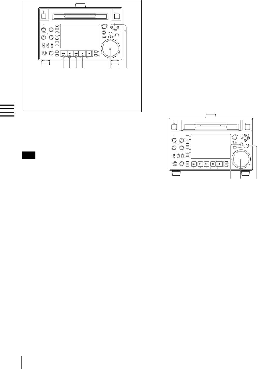
64 Playback
Chapter 4 Recording and Playback
To start playback
Press the PLAY button.
Playback starts.
When two or more clips are recorded on the disc, they are
played back continuously.
No audio is output when non-audio signals are played
back.
To jump to the next or previous clip, then start
playback
Use the PREV button, NEXT button, jog dial, or shuttle
dial.
To stop playback
Press the STOP button.
If you play back to the end of the last clip, playback
automatically stops.
If, in this state, you press the PLAY button, the message
“Disc End!” appears on the display.
To carry out playback again, move back to the desired clip
using the PREV button, jog dial or shuttle dial.
To set shot marks
While playing back a disc, you can set essence marks such
as Shot Mark1 and Shot Mark2 in desired frames.
To set a Shot Mark1 or Shot Mark2, hold down the V/
MARK1 or v/MARK2 button and press the PUSH
SET(S.SEL) knob. If you connect a Windows USB
keyboard to the MAINTENANCE connector, you can
record shot marks from Shot Mark0 up to Shot Mark9 by
pressing the 0 to 9 keys on the numeric keypad.
Use the PDZ-1Proxy Browsing Software on the supplied
XDCAM Application Software CD-ROM to delete and
modify essence marks.
See page 170 for an overview of the PDZ-1 software and
information about how to install it.
You can also delete and modify essence marks from the
Thumbnail Menu of the chapter thumbnail screen (see
page 75).
To set a clip flag
You can set one of the three types of flag (OK, NG or
KEEP) for the clip while it is being played back by
viewing its video image and using the function menu (see
page 51).
Playback in jog mode
In jog mode, you can control the speed of playback by the
speed of turning the jog dial. The playback speed range is
–1 to +1 times normal speed.
To carry out playback in jog mode, proceed as follows.
1
Press the SHTL/JOG button or VAR/JOG button,
turning it on.
2
Turn the jog dial in the desired direction, at the speed
corresponding to the desired playback speed.
Playback in jog mode starts.
3
To stop playback in jog mode, stop turning the jog dial.
When setup menu item 101 SELECTION FOR
SEARCH DIAL ENABLE is set to “dial” (factory
default setting), you can start jog playback by simply
rotating the jog dial, even when the SHTL/JOG and
VAR/JOG buttons are not lit.
Playback in shuttle mode
In shuttle mode, you can control the speed of playback by
the angular position of the shuttle dial. The range of
playback speed is ±20 times normal speed.
To carry out playback in shuttle mode, proceed as follows.
Note
REC
NET
REMOTE
LOCAL
VARIABLE KEY INHI
PRE-
SET
ON
OFF
PB
PHONES LEVEL
SHIFT
DISPLAY
HOME
PAG E
EXPAND
CHAPTER
TOP F REV F FWD END STANDBY REC INHI
PREV NEXTPLAY STOP REC THUMBNAIL
RETURN
PUSH SET(S.SEL)
MENU
RESET
MARK2
MARK1
IN OUT
SHTL/JOG
SUB CLIP
DISC MENU
VAR/JOG
EJECT
ACCESS
CH-1
ALL CH
CH-2
CH-3
CH-4
651 2 3 4 7
1PREV button
2PLAY button
3NEXT button
4STOP button
5Jog dial
6Shuttle dial
7V/MARK1 button and v/MARK2 button
REC
NET
REMOTE
LOCAL
VARIABLE KEY INHI
PRE-
SET
ON
OFF
PB
PHONES LEVEL
SHIFT
DISPLAY
HOME
PAG E
EXPAND
CHAPTER
TOP F REV F FWD END STANDBY REC INHI
PREV NEXTPLAY STOP REC THUMBNAIL
RETURN
PUSH SET(S.SEL)
MENU
RESET
MARK2
MARK1
IN OUT
SHTL/JOG
SUB CLIP
DISC MENU
VAR/JOG
EJECT
ACCESS
CH-1
ALL CH
CH-2
CH-3
CH-4
2,3 11
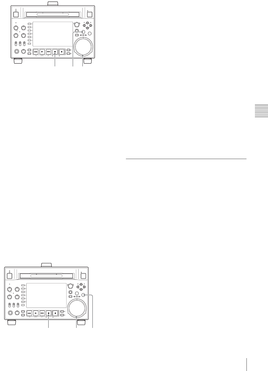
65
Playback
Chapter 4 Recording and Playback
1
Press the SHTL/JOG button, turning it on.
2
Turn the shuttle dial to the desired angle
corresponding to the desired playback speed.
Playback in shuttle mode starts.
3
To stop playback in shuttle mode, return the shuttle
dial to the center position, or press the STOP button.
When setup menu item 101 SELECTION FOR
SEARCH DIAL ENABLE is set to “dial” (factory
default setting), you can start shuttle playback by
simply rotating the shuttle dial, even when the SHTL/
JOG button is not lit.
To alternate between normal-speed playback and
shuttle mode playback
Set the shuttle dial to the position corresponding to the
desired shuttle playback speed, then switch between
normal-speed playback and shuttle playback by pressing
the PLAY and SHTL/JOG buttons alternately.
Playback in variable-speed mode
In variable-speed mode, you can control the speed of
playback in the range of –2 to +2 times normal speed. (You
can use setup menu item 119 VARIABLE SPEED LIMIT
IN KEY to specify the speed range of variable playback.)
To carry out playback in variable-speed mode, proceed as
follows.
1
Press the VAR/JOG button, turning it on.
2
Turn the shuttle dial to the desired angle
corresponding to the desired playback speed.
Playback in variable-speed mode starts.
3
To stop playback in variable-speed mode, return the
shuttle dial to the center position, or press the STOP
button.
To alternate between normal-speed playback and
variable-speed mode playback
Set the shuttle dial to the position corresponding to the
desired variable playback speed, then switch between
normal-speed playback and variable-speed mode playback
by pressing the PLAY and VAR/JOG buttons alternately.
To perform manual frame sync playback
During playback, you can adjust the playback output phase
in units of one frame. To do so, hold down the PLAY
button and turn the PUSH SET(S.SEL) knob in either
direction.
To speed up the phase: Turn clockwise.
To delay the phase: Turn counterclockwise.
Playback operations using
thumbnails
Playback operations that you can perform with thumbnails
include searching for clips, displaying clip information,
playing clip lists created with the scene selection function,
and locking and deleting clip. This allows you to check the
actual video as you work.
See “Thumbnail Operations” (page 74) for more
information about thumbnail operations, and “Scene
Selection (Clip List Editing)” (page 85) for more
information about the scene selection function.
REC
NET
REMOTE
LOCAL
VARIABLE KEY INHI
PRE-
SET
ON
OFF
PB
PHONES LEVEL
SHIFT
DISPLAY
HOME
PAG E
EXPAND
CHAPTER
TOP F REV F FWD END STANDBY REC INHI
PREV NEXTPLAY STOP REC THUMBNAIL
RETURN
PUSH SET(S.SEL)
MENU
RESET
MARK2
MARK1
IN OUT
SHTL/JOG
SUB CLIP
DISC MENU
VAR/JOG
EJECT
ACCESS
CH-1
ALL CH
CH-2
CH-3
CH-4
2,33 1

66 Overview
Chapter 5 Operations in GUI Screens
Chapter5
Operations in GUI
Screens
Overview
You can perform scene searches, play the searched scenes,
and select scenes (edit clip list) in Graphical User Interface
(GUI) screens. The GUI screens are your gateways to discs
and the data saved on discs.
(The GUI screens can display European languages,
Japanese, Korean, Simplified Chinese, and Traditional
Chinese for clip names and titles.)
Switching between GUI screens
The most important GUI screens are:
Clip thumbnail screen: displays thumbnails of clips on
the disc. “Clip” is displayed as the title at the upper
left of the screen (see page 67).
Clip list thumbnail screen: displays thumbnails of sub
clips in a clip list. “Clip List” is displayed as the title
at the upper left of the screen (see page 67).
There are also two playback screens:
Clip playback screen: playback screen for normal video
Clip list playback screen: playback screen for clip list
video
You will use the THUMBNAIL button 1 and the SUB
CLIP/DISC MENU button 2 to switch between these
four screens. Each press of these buttons switches between
the screens as shown in the following figure. The
THUMBNAIL and SUB CLIP/DISC MENU indicators
light as follows, according to the type of screen that is
currently displayed.
To switch between these four screens, a disc with recorded
clips must be loaded in the unit.
Note
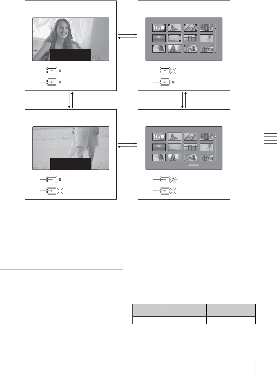
67
Overview
Chapter 5 Operations in GUI Screens
The other thumbnail screens are:
• Expand thumbnail screen
• Chapter thumbnail screen
• Essence mark thumbnail screen
Information and controls in
thumbnail screens
About the display of clip and clip list
names
You can specify that titles should appear instead of names
in the clip name areas of thumbnail screens. You can also
change the display language.
To specify that titles, if they exist, should be displayed
with higher priority than names, select one of the following
under Settings >Display Title in the Disc Menu.
On: Title1 "title1": Display in the order title1, title2, clip
or clip list name.
On: Title2 {title2}: Display in the order title2, title1, clip
or clip list name.
To change the display language according to the area of
use (see page 33), select the desired language under
Settings >Select Font in the Disc Menu.
THUMBNAIL
SUB CLIP
DISC MENU
1
1
22
THUMBNAIL
SUB CLIP
DISC MENU
THUMBNAIL
SUB CLIP
DISC MENU
THUMBNAIL
SUB CLIP
DISC MENU
TCR 00 : 23 : 00 . 26
JOG STILL
001/036
TCR 00 : 00 : 18 . 01
SHUTTLE STILL
F0008 : 003/005
Clip List:E0001 002/013
TC 00:00:00:00
TC 00:00:28:08
TC 00:00:59:16
DATE&TIME
28 JUL 2006 19:55
TOTAL DUR
00:01:31:16
TC 00:00:04:14
TC 00:00:35:15
TC 00:01:06:18
TC 00:00:12:04
TC 00:00:46:08
TC 00:01:13:11
TC 00:00:20:13
TC 00:00:53:22
TC 00:01:17:27
Clip:C0006 006/040
TC 00:23:00:25
TC 00:25:49:23
TC 00:28:06:09
DATE&TIME
30 NOV 2005 13:38
DUR
0:00:10:23
TC 00:23:40:07
TC 00:26:22:10
TC 00:28:22:02
TC 00:24:45:11
TC 00:27:19:04
TC 00:23:34:18
TC 00:25:06:14
TC 00:27:51:09
TC 00:23:54:22
22
1
1
1
2
1
2
1
2
1
2
Clip list playback screen a), b)
Clip thumbnail screen
Clip list thumbnail screen b)
Clip playback screen a)
Unlit
Unlit
Lit
Unlit
Unlit
Lit
Lit
Lit
a) Playback screens appear when you switch to video monitor display. Use the DISPLAY button to switch from the basic monitor
display to video monitor display (see page 21).
b) The clip list playback screen appears when a clip list is loaded into the unit’s memory (see page 90).
Area of use
setting Select Font
setting Displayable
languages
J (for Japan) – English/Japanese
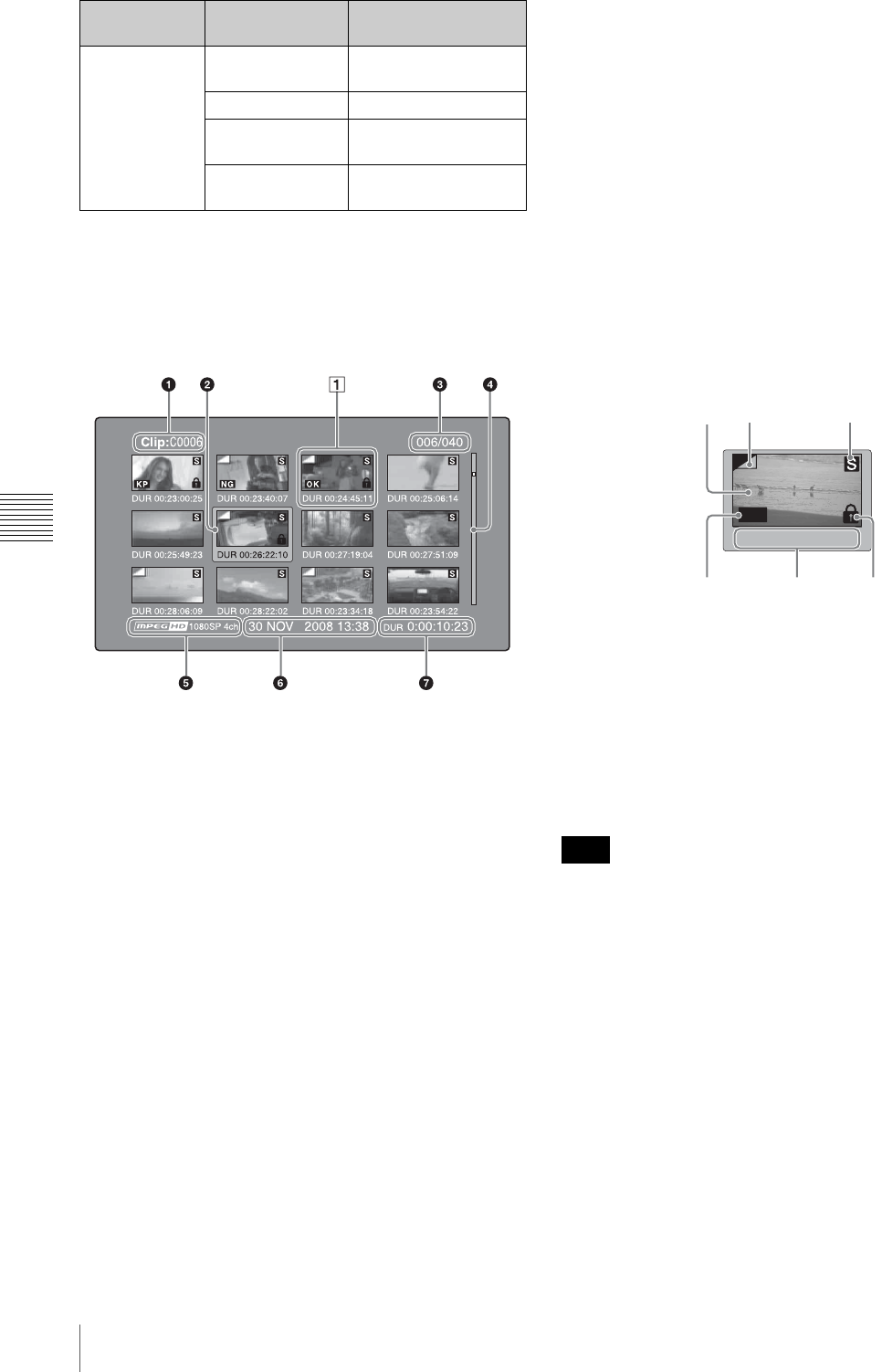
68 Overview
Chapter 5 Operations in GUI Screens
Clip thumbnail screen
This screen displays thumbnails of clips on the disc in the
order that they were recorded. You can use this screen to
work with clips – deleting or locking them, selecting their
index pictures, adding them to clip lists, and so on.
aClip name
Displays the name or a title of the selected clip (see
page 67).
bSelection frame
Indicates that the thumbnail is selected. To select another
thumbnail, move the frame (see page 73). Multiple
selection frames appear when multiple thumbnails are
selected (see page 73).
cClip number/total number of clips
Displays the total number of clips on the disc, and the
number of the selected clip.
dScrollbar
When not all of the thumbnails can be displayed in the
thumbnail display area, the position of the slider shows the
relative position of the currently displayed clips, and the
length of the slider shows the relative length of currently
displayed clips within all of the clips.
When you have a large number of thumbnails, you can
save time by using the Skip Scroll function to jump
directly to the thumbnail you want (see page 74).
eRecording format
The recording format of the selected clip is displayed as a
combination of the following information.
• Video format logo
• Number of system lines
• Recording quality
• Number of audio channels
fClip date and time
Displays the date and time when the selected clip was shot
and recorded.
gDuration
Displays the duration (recording time) of the selected clip.
When multiple clips are selected, displays the total
recording time of the selected clips.
AThumbnail display items
aIndex picture
Displays an image to stand for the content of the clip. The
index picture is normally the first frame of the clip.
bIndex picture changed mark
This mark, like the folded-over corner of a page that you
want to remember, appears when the index picture has
been changed to any frame other than the first frame of a
clip (see page 79).
When you cue up a clip, the unit always cues up the first
frame, even when the index picture has been changed to a
different frame.
cS mark
This mark appears when shot marks or other essence
marks have been set in the clip (see page 55).
The chapter thumbnail screen can be displayed for clips
that show this mark (see page 69).
dClip flag icon
Displays the corresponding icon when a clip flag (OK/NG/
KP (KEEP)) is set in the clip.
eClip and frame information
Displays the clip or frame information selected with the
Clip Information item in the Thumbnail Menu (see
UC (for regions
outside Japan) European
Alphabet English/European
languages
Korean English/Korean
Simplified
Chinese English/Simplified
Chinese
Traditional
Chinese English/Traditional
Chinese
Area of use
setting Select Font
setting Displayable
languages
Note
TC 00:26:22:10
OK
546
213
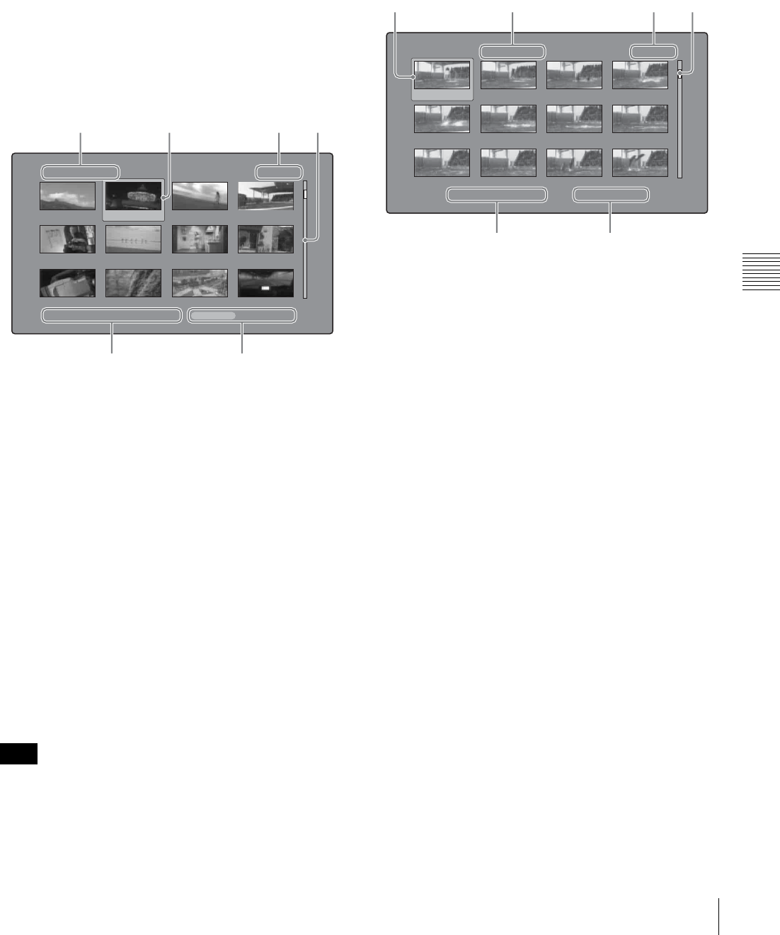
69
Overview
Chapter 5 Operations in GUI Screens
page 79). The factory default selection is the timecode of
the first frame or the timecode of the thumbnail frame.
fLock icon
This icon appears when the clip is locked (protected) (see
page 83). Clips cannot be deleted and their clip
information cannot be changed when this mark is
displayed.
Clip list thumbnail screen
This screen displays thumbnails of the clips in the current
clip list. You can use this screen to create and edit clips
lists.
aClip list name
Displays the name or a title of the clip list (see page 67).
bSelection frame
See the description in “Clip thumbnail screen” (page 68).
cSub clip number/number of sub clips
Displays the total number of sub clips in the clip list, and
the number of the selected sub clip.
dScrollbar
See the description in “Clip thumbnail screen” (page 68).
eClip list date and time
Displays the date and time when the clip list was created,
or the date and time of its most recent modification. An
asterisk (*) appears after the date and time of creation
when the current clip list has not been saved to the disc.
“New File” appears when no clip list has been loaded into
the unit’s memory, and when a clip list has been cleared
from the unit’s memory.
fTotal duration
Displays the total duration of all sub clips in the clip list.
Expand thumbnail screen
This screen displays thumbnails of equally sized divisions
of the selected clip.
aSelection frame
See the description in “Clip thumbnail screen” (page 68).
bClip number/total clips × number of divisions
Displays the number of the selected clip, the total number
of clips on the disc, and the number of times that the
selected clip has been divided to display the expansion
thumbnails.
cThumbnail number/total thumbnails
Displays the total number of expanded thumbnails and the
number of the selected thumbnail.
dScrollbar
See the description in “Clip thumbnail screen” (page 68).
eClip name
Displays the name or a title of the expanded clip (see
page 67).
fDuration
Displays the time from the selected thumbnail to the next
one.
Chapter thumbnail screen
Chapters are the sections between the shot marks, Rec
Start marks, and other essence marks that have been
recorded in clips. This screen allows you to display
thumbnails of the chapters in the selected clip.
Note
Clip List:E0001 002/013
TC 00:00:00:00
TC 00:00:28:08
TC 00:00:59:16
DATE&TIME 28 JUL 2006 19:55 TOTAL DUR 00:01:31:16
TC 00:00:04:14
TC 00:00:35:15
TC 00:01:06:18
TC 00:00:12:04
TC 00:00:46:08
TC 00:01:13:11
TC 00:00:20:13
TC 00:00:53:22
TC 00:01:17:27
12
56
34
Expand Clip 008/024 x 12 001/012
TC 00:01:35:17
TC 00:01:37:11
TC 00:01:39:06
TC 00:01:38:00
TC 00:01:37:24
TC 00:01:38:19
TC 00:01:36:14
TC 00:01:38:08
TC 00:01:40:02
TC 00:01:36:27
TC 00:01:38:22
TC 00:01:40:16
CLIP Tene DUR 0:00:00:13
1
56
3
24

70 Overview
Chapter 5 Operations in GUI Screens
Shot marks can be set by the user during recording and
playback. They can be deleted and moved.
Essence marks other than shot marks are set automatically.
They cannot be deleted or moved.
aSelection frame
See the description in “Clip thumbnail screen” (page 68).
bClip number/total clips
Displays the total number of clips on the disc and the
number of the clip that contains the displayed chapters.
If the essence mark name is a user-defined name, it is
displayed between quotation marks, for example as
[Chapter: "Touch Down"] (see page 93).
cS1/S2/RS marks
The “S1”, “S2”, and “RS” marks on the thumbnails
indicate frames where Shot Mark1, Shot Mark2, and Rec
Start essence marks are set.
dChapter number/total chapters
Displays the total number of chapters and the number of
the selected chapter.
The total number of chapters is the total number of
chapters in the specified clip only.
eScrollbar
See the description in “Clip thumbnail screen” (page 68).
fClip name
Displays the name or a title of the clip whose chapter is
displayed (see page 67).
gDuration
Displays the time from the first frame of the selected
chapter to the first frame of the next chapter.
Essence mark thumbnail screen
This screen displays thumbnails of the specified essence
mark, found by searching all clips on the disc.
aEssence mark name
Displays the name of the essence mark (Shot Mark1 here).
If the shot mark name has been defined by the user, it is
enclosed in quotation marks (" ") in the display (see
page 93).
bSelection frame
See the description in “Clip thumbnail screen” (page 68).
cEssence mark number/total essence marks
Displays the total number of essence marks and the
number of the selected essence mark.
The total number of essence marks is the total number of
essence marks that have been set in all clips on the disc.
dScrollbar
See the description in “Clip thumbnail screen” (page 68).
eClip date and time
Displays the date and time when the clip that contains the
selected thumbnail was recorded or last modified.
fClip name
Displays the name or a title of the clip that contains the
selected frame (see page 67).
Displaying menus
Thumbnail Menu
The Thumbnail Menu displays menu items that are valid
for the currently displayed thumbnail screen.
Note
Note
Chapter of Clip 001/024 001/003
TC 00:23:00:25 TC 00:23:02:00 TC 00:23:04:00
CLIP C0001 DUR 0:00:01:05
3142
7
6
5
Note
Shot Mark1 001/029
TC 00:23:02:00
TC 00:26:22:11
TC 00:28:35:00
30 NOV 2006 19:55 "Capping literally years of spe..."
TC 00:24:45:25
TC 00:27:19:25
TC 00:28:55:02
TC 00:25:07:01
TC 00:27:51:25
TC 00:29:10:05
TC 00:25:40:24
TC 00:28:06:17
TC 00:29:20:03
12
56
34
71
Overview
Chapter 5 Operations in GUI Screens
To display the Thumbnail Menu
To display the Thumbnail Menu, press the MENU button
with a thumbnail screen displayed. To return to the original
screen, press the MENU button again, or press the RESET/
RETURN button.
Shortcut operations
Shortcut button names are displayed next to the menu
items of commands that have shortcuts (see page 103).
Shortcuts displayed within parentheses should be used
with all menus closed.
Thumbnail Menu submenus
• The Thumbnail Search Menu contains the basic
commands for thumbnail searches.
• The Thumbnail View Menu contains the basic
commands for moving to other menus.
Disc Menu
The Disc Menu allows you to do the following.
REC
NET
REMOTE
LOCAL
VARIABLE KEY INHI
PRE-
SET
ON
OFF
PB
PHONES LEVEL
SHIFT
DISPLAY
HOME
PAG E
EXPAND
CHAPTER
TOP F REV F FWD END STANDBY REC INHI
PREV NEXTPLAY STOP REC THUMBNAIL
RETURN
PUSH SET(S.SEL)
MENU
RESET
MARK2
MARK1
IN OUT
SHTL/JOG
SUB CLIP
DISC MENU
VAR/JOG
EJECT
ACCESS
CH-1
ALL CH
CH-2
CH-3
CH-4
21
1MENU button
2RESET/RETURN button
Note
Clip thumbnail screen
1 or 2
Thumbnail Menu of the clip thumbnail screen
1
Item Operation/Setting
Load Clip List Load clip list into this unit’s memory.
Save Clip List Save a clip list on the disc under its current name, overwriting the old
contents.
Save Clip List as… Save a clip list on the disc under a new name.
Delete Clip List Delete a clip list from the disc.
Clear Clip List Clear the current clip list from the unit’s memory.
Load Planning Metadata/Select Drive Select a media disc or drive and load planning metadata into this
unit’s memory.
Planning Metadata Properties Display the properties of the currently loaded planning metadata.
Clear Planning Metadata Clear the currently loaded planning metadata from the unit’s memory.

72 Overview
Chapter 5 Operations in GUI Screens
To display the Disc Menu
To display the Disc Menu, press the SUB CLIP/DISC
MENU button with the SHIFT button held down in one of
the following screens.
• Clip thumbnail screen
• Clip list thumbnail screen
• Clip playback screen
• Clip list playback screen
To return to the original screen, press the RESET/
RETURN button.
Lock or Delete All Clips Sub-Item
Lock All Clips Lock all clips.
Unlock All Clips Unlock all clips.
Delete All Clips Delete all clips.
Disc Properties Display the properties of the currently loaded disc. Or edit the user
disc ID, title 1, and title 2.
Format Disc Format (initialize) the currently loaded disc.
Download Clip via Direct FTP Used to send clip to and from remote devices and remote computers.
Settings Sub-Item
SET Key on Thumbnail Selects the behavior of the unit when the PUSH SET(S.SEL) knob is
pressed with one thumbnail selected.
Cue up & Still: Cue up the selected thumbnail.
Cue up & Play: Cue up and play the selected thumbnail.
Sort Clip List by… Selects a method to sort the clip list.
Name (A-Z): Sort in ascending alphabetic order.
Date (Newest First): Sort by date and time of creation, newest clip
list first.
Sort Planning Metadata
by... Selects a method to sort the planning metadata.
Name (A-Z): Sort in ascending alphabetic order.
Date (Newest First): Sort by date and time of creation, newest
planning metadata first.
Display Title Selects whether to display clip and clip list titles.
On: Title1 "title1": Display the title in the following order of priority:
Title1, Title2, Clip name or Clip list name.
On: Title2 {title2}: Display the title in the following order of priority:
Title2, Title1, Clip name or Clip list name.
Off: Do not display the title. Always display the clip name or clip list
name.
Planning Clip Name in Clip
Info. Area Selects whether to display in the video monitor screen the title
contained in a planning metadata file that is loaded into this unit.
Off: Do not display title.
ASCII Clip Name: Display title in ASCII format.
Clip Name: Display title in UTF-8 format.
Disable “Format Disc” Selects whether to disable the Format Disc command.
Disable: Disable the command.
Enable: Enable the command.
Select Font Selects the language (font) used to display clip names, clip list
names, and title2 clip titles.
Select USB Keyboard
Language Selects a language of the USB keyboard used on the software
keyboard.
Select Mouse Pointer
Speed Selects the speed of the USB mouse pointer used on the software
keyboard from the following values.
5 Fast/4/3 Middle/2/1 Slow
Item Operation/Setting
73
Overview
Chapter 5 Operations in GUI Screens
GUI screen operations
To select items
Do one of the following to select thumbnails, menu items,
timecode digits, and other items.
• Turn the PUSH SET(S.SEL) knob.
• Turn the jog or shuttle dial.
•Press the V/MARK1, v/MARK2, B/IN or b/OUT
button.
• Press the PREV or NEXT button.
• With the SHIFT button held down, press the PREV or
NEXT button (to move to the first or last item).
• With the SHIFT button held down, press the V/MARK1
or v/MARK2 button (to move to the previous or next
page).
To select multiple thumbnails
Do one of the following
• Turn the PUSH SET(S.SEL) knob with the SHIFT
button held down.
• With the SHIFT button held down, press the B/IN or b/
OUT button.
To return to the previous screen
Press the RESET/RETURN button.
To move from a menu level to the next
lower or higher menu level
For a menu item displayed together with b or B, you can
move to the next lower or higher menu level by pressing
the B/IN or b/OUT button.
REC
NET
REMOTE
LOCAL
VARIABLE KEY INHI
PRE-
SET
ON
OFF
PB
PHONES LEVEL
SHIFT
DISPLAY
HOME
PAG E
EXPAND
CHAPTER
TOP F REV F FWD END STANDBY REC INHI
PREV NEXTPLAY STOP REC THUMBNAIL
RETURN
PUSH SET(S.SEL)
MENU
RESET
MARK2
MARK1
IN OUT
SHTL/JOG
SUB CLIP
DISC MENU
VAR/JOG
EJECT
ACCESS
CH-1
ALL CH
CH-2
CH-3
CH-4
3
21
1SHIFT button
2SUB CLIP/DISC MENU button
3RESET/RETURN button
Clip List:E0001 002/013
TC 00:00:00:00
TC 00:00:28:08
TC 00:00:59:16
DATE&TIME 28 JUL 2006 19:55 TOTAL DUR 00:01:31:16
TC 00:00:04:14
TC 00:00:35:15
TC 00:01:06:18
TC 00:00:12:04
TC 00:00:46:08
TC 00:01:13:11
TC 00:00:20:13
TC 00:00:53:22
TC 00:01:17:27
Load Clip List
Save Clip List
Save Clip List as...
Delete Clip List
Clear Clip List
Load Planning Metadata/Select Drive
Planning Metadata Properties
Clear Planning Metadata
Lock or Delete All Clips
Disc Menu
C
lip list thumbnail screen
1+23
REC
NET
REMOTE
LOCAL
VARIABLE KEY INHI
PRE-
SET
ON
OFF
PB
PHONES LEVEL
SHIFT
DISPLAY
HOME
PAG E
EXPAND
CHAPTER
TOP F REV F FWD END STANDBY REC INHI
PREV NEXTPLAY STOP REC THUMBNAIL
RETURN
PUSH SET(S.SEL)
MENU
RESET
MARK2
MARK1
IN OUT
SHTL/JOG
SUB CLIP
DISC MENU
VAR/JOG
EJECT
ACCESS
CH-1
ALL CH
CH-2
CH-3
CH-4
46 5
321
1PUSH SET(S.SEL) knob
2B/IN, b/OUT button
3V/MARK1, v/MARK2 button
4Jog and shuttle dials
5RESET/RETURN button
6SHIFT button

74 Thumbnail Operations
Chapter 5 Operations in GUI Screens
To scroll hidden parts of the string into
view
When a b or B mark is displayed for an item, you can
press the B/IN or b/OUT button to scroll the display by
one character for each press.
The V/MARK1 and v/MARK2 buttons scroll the
beginning and end of the string into view.
To increment and decrement numbers
Do one of the following.
• Press the V/MARK1 or v/MARK2 button.
• Turn the PUSH SET(S.SEL) knob.
• Turn the jog dial.
To confirm selections
Press the PUSH SET(S.SEL) knob.
Thumbnail Operations
You can use thumbnail screens to display clip information
and to find, protect, and delete clips. The thumbnails
provide visual confirmation of these and other operations.
Selecting thumbnails
The thumbnail selection frame (see page 68) indicates the
currently selected thumbnail.
To move the thumbnail selection frame
Turn the PUSH SET(S.SEL) knob.
To skip quickly through thumbnails (Skip
Scroll function)
When you have a large number of thumbnails, like in
expand thumbnail screen, you can use the Skip Scroll
function to skip through them quickly.
See page 73 for more information about operations in
thumbnail screens.
1
In the screens like clip thumbnail screen or expand
thumbnail screen, display the Thumbnail Menu.
2
Select Skip Scroll, and then press the PUSH
SET(S.SEL) knob.
A small popup window appears on the scrollbar to
indicate the position of the currently selected
thumbnail within the set of all thumbnails.
3
Turn the PUSH SET(S.SEL) knob.
The current position moves by an amount equal to 1/10
of the total number of thumbnails.
When you reach a point that is close to the thumbnail
you want, turn the jog dial to move the selection frame
in units of 1 thumbnail.
"Seashore" DUR
Expand 007/235
DUR 0:00:00:01
DUR 0:00:00:01
DUR 0:00:00:01
DUR 0:00:00:01
DUR 0:00:00:01
DUR 0:00:00:01
DUR 0:00:00:01
DUR 0:00:00:01
DUR 0:00:00:01
DUR 0:00:00:01
DUR 0:00:00:01
CLIP 0:00:00:01
DUR 0:00:00:01
007/235
Skip Scroll
75
Thumbnail Operations
Chapter 5 Operations in GUI Screens
4
Press the PUSH SET(S.SEL) knob at the new position.
The thumbnail at the position indicated in the small
popup window appears in a thumbnail screen like the
following 1).
1)Expand thumbnail screen
To select multiple thumbnails
Move the selection frame to the first thumbnail that you
want to select. Then, with the SHIFT button held down,
turn the PUSH SET(S.SEL) knob.
To cancel the multiple selection, move the selection frame
without the SHIFT button held down.
Searching with thumbnails
By using the thumbnails that appear in the various
thumbnail screens, you can easily cue up and play clips
and sub clips.
Using thumbnails to find clips
The clip thumbnail screen displays thumbnails of all clips
recorded on the disc. You can use this screen to cue up the
selected clip and to carry out playback (see page 77).
See “Selecting thumbnails” (page 74) for more
information.
Using the expand function to find scenes
The expand function allows you to divide a selected clip
into equally sized blocks, and to display thumbnails of the
first frame in each block. This is a quick and efficient way
to review the selected clip and search for target scenes.
You can specify 12, 144, or 1728 divisions.
The maximum number of blocks may be other than 1728
when the recorded duration of the clip is short. In this case,
the frame interval of expanded thumbnails is fixed at 1
frame. This allows you to view expanded thumbnails at
equal intervals.
See page 73 for more information about thumbnail screen
operations.
1
In the clip thumbnail screen, select the thumbnail of
the clip that contains the scene you want to find.
2
Press the EXPAND button.
The selected clip is divided into 12 blocks, and a list
appears in the expand thumbnail screen (see page 69)
with the first frame of each block displayed as a
thumbnail.
3
Select the thumbnail that you want to expand further.
4
Repeat steps 2 and 3 up to 2 times, as required.
Thumbnails cannot be further expanded when they already
have the minimum duration (1 frame).
To return to the previous expansion level
Press the EXPAND button with the SHIFT button held
down.
To display the expand thumbnail screen of the
previous or next clip
With the expand thumbnail screen still active, press the
PREV button or the NEXT button.
Using the chapter function to find scenes
Chapters are the sections between the shot marks, Rec
Start marks, and other essence marks.
Rec Start essence marks are set automatically at the start of
recording, but shot marks can be set at any scene during
recording or playback.
The chapter function allows you to display thumbnails of
the chapters in a clip.
"Seashore" DUR
Expand 007/235
DUR 0:00:00:01
DUR 0:00:00:01
DUR 0:00:00:01
DUR 0:00:00:01
DUR 0:00:00:01
DUR 0:00:00:01
DUR 0:00:00:01
DUR 0:00:00:01
DUR 0:00:00:01
DUR 0:00:00:01
DUR 0:00:00:01
CLIP 0:00:00:01
DUR 0:00:00:01
Clip:"Navigating sibling relati..." 018/036
TC 00:29:19:23
TC 00:30:40:13
TC 00:24:34:27
DATE&TIME 30 NOV 2005 14:14 DUR 0:23:22:26
TC 00:29:38:25
TC 01:01:28:25
TC 00:24:46:22
TC 00:29:50:04
TC 00:09:43:14
TC 00:25:42:08
TC 00:30:25:11
TC 00:24:24:29
TC 00:25:49:07
Note
Note
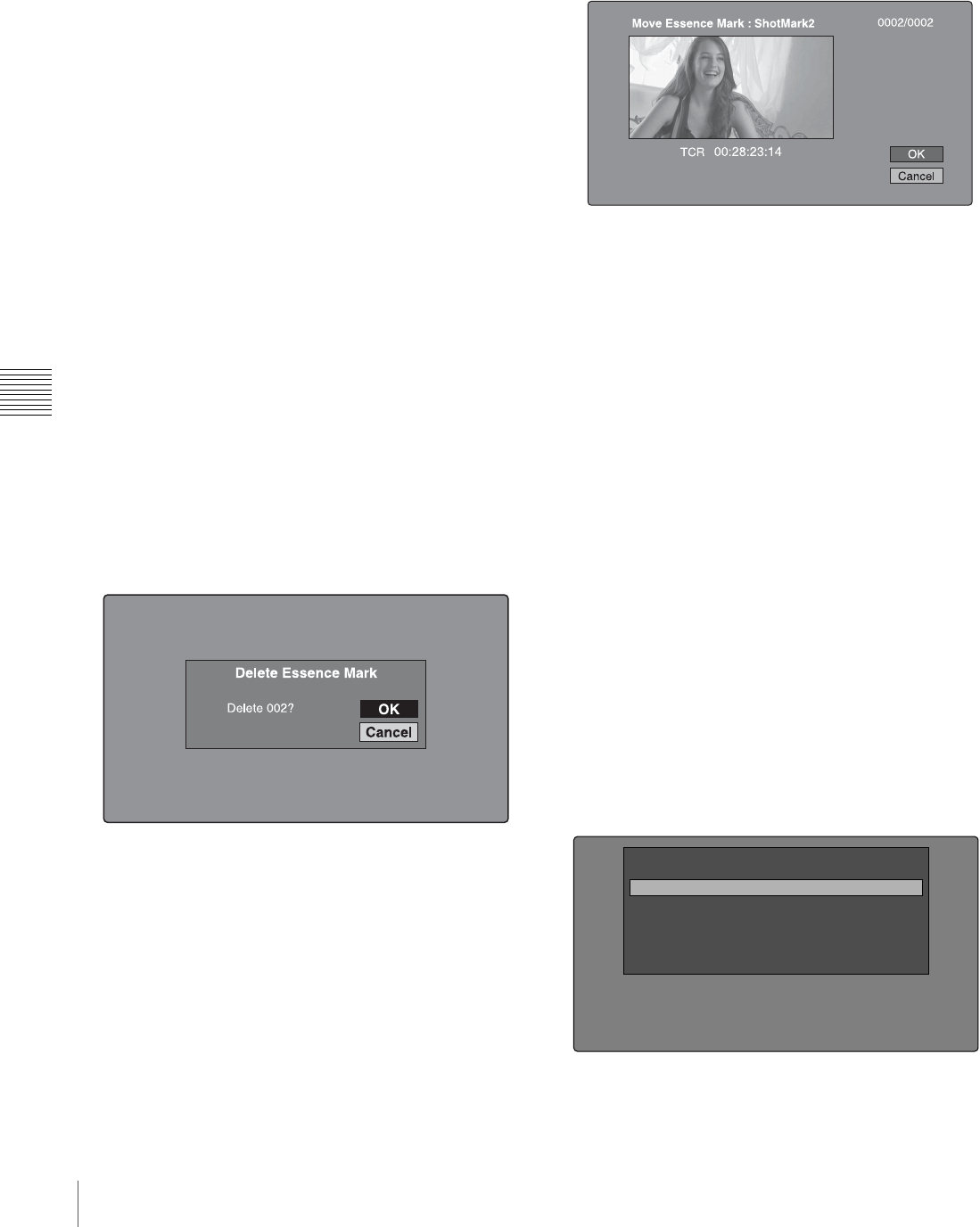
76 Thumbnail Operations
Chapter 5 Operations in GUI Screens
See “To set shot marks” (page 55) for more information.
See page 73 for more information about thumbnail screen
operations.
1
In the clip thumbnail screen, select the thumbnail of a
clip with chapters set.
The “S” mark appears on the thumbnails of clips with
chapters set.
2
Press the CHAPTER button.
The chapter thumbnail screen (see page 69) appears,
with thumbnails of the frames where chapters are set.
The “S1”, “S2”, and “RS” marks on the thumbnails
indicate frames where Shot Mark1, Shot Mark2, and
Rec Start essence marks are set.
To delete the shot mark at a chapter position
You can delete the shot mark (Shot Mark0 to 9) at the
chapter position in the chapter thumbnail screen. (Rec
Start cannot be deleted.).
1
In the chapter thumbnail screen, select the thumbnail
for the frame whose shot mark you want to delete.
2
Display the Thumbnail Menu.
3
Select Delete Essence Mark.
A message appears asking if you are sure that you want
to delete the shot mark.
4
Select OK to delete the mark, or Cancel to cancel the
deletion, and then press the PUSH SET(S.SEL) knob.
To adjust the position of shot marks at chapter
positions
You can use the chapter thumbnail screen to adjust the
position of shot marks (Shot Mark0 to 9) at chapter
positions. (The positions of Rec Start essence marks
cannot be adjusted.)
1
In the chapter thumbnail screen, select the thumbnail
of the shot mark whose position you want to adjust.
2
Display the Thumbnail Menu.
3
Select Move Essence Mark.
The Move Essence Mark screen is displayed.
You can perform playback and searches in this screen.
4
Use the PLAY button or jog dial to display the frame
you want.
5
Select OK, and then press the PUSH SET(S.SEL)
knob.
To display the chapter thumbnail screen of the
previous or next clip with chapters
With the chapter thumbnail screen still active, press the
PREV button or the NEXT button.
The unit searches in the reverse or forward direction for the
next clip with chapters, beginning with the previous or
next clip.
Using essence marks to find scenes
See page 73 for more information about thumbnail screen
operations.
1
In the clip playback screen or the clip thumbnail
screen, press the THUMBNAIL button with the
SHIFT button held down.
The Select Essence Mark screen appears.
The names of essence marks that are not recorded on
the disc are displayed in gray.
Shot Mark1
Shot Mark2
Rec Start
Cut
Others
Select Essence Mark

77
Thumbnail Operations
Chapter 5 Operations in GUI Screens
If planning metadata with user-defined essence
mark has been loaded
You can select user-defined essence marks (see
page 93).
2
Select the essence mark that you want, and then press
the PUSH SET(S.SEL) knob.
The essence mark thumbnail screen displays a list of
frames where the selected essence mark is set.
To switch directly to the Rec Start essence mark
thumbnail screen
Before starting, set setup menu item 153 FIND MODE to
“clip & rec start mark”.
By pressing the DISPLAY button in the clip thumbnail
screen, you can switch directly to the Rec Start essence
mark thumbnail screen. As long as the setting of setup
menu item 153 does not change, the DISPLAY button
switches between the clip thumbnail screen and the Rec
Start essence mark thumbnail screen.
This setting allows you to use the DISPLAY button as a
shortcut to Rec Start essence mark thumbnail screen,
which is convenient for checking start points in clip
recorded with the Clip Continuous Rec function.
Also, when the Rec Start essence mark thumbnail screen is
displayed, each press of the THUMBNAIL button
switches between that screen and the clip playback screen
(Resume function). In the clip playback screen, the PREV
and NEXT buttons jump to the previous or next recording
start points.
The DISPLAY button does not switch to the Rec Start
essence mark thumbnail screen from the expand thumbnail
screen or the chapter thumbnail screen.
Playing the scene you have found
After finding a clip with one of the methods explained in
the previous section, “Searching with thumbnails” (see
page 75), you can cue up and play the clip that you have
found.
To search for a thumbnail position and cue
it up
See page 73 for more information about GUI screen
operations.
1
Select the thumbnail that you want to cue up.
2
Press the PUSH SET(S.SEL) knob.
To play clips with the PUSH SET(S.SEL) knob
In the Disc Menu, set Settings >SET Key on Thumbnail to
“Cue up & Play”. Playback begins from the selected frame
when you press the PUSH SET(S.SEL) knob, in the same
way as when you press the PLAY button.
To search for a thumbnail position and
play from there
See page 73 for more information about GUI screen
operations.
1
Select the thumbnail that you want to play.
2
Press the PUSH SET(S.SEL) button.
Selecting clips by type (Filter Clips
function)
You can select clips of a certain type from among all of the
clips on a disc (Filter Clips function). For example, you
can do the following.
Note
Clip:C0010 010/041
TC 00:23:00:25
TC 00:25:49:23
TC 00:28:06:09
DATE&TIME 30 NOV 2005 13:40 DUR 0:00:04:14
TC 00:23:40:07
TC 00:26:22:10
TC 00:28:22:02
TC 00:24:45:11
TC 00:27:19:04
TC 00:23:34:18
TC 00:25:06:14
TC 00:27:51:09
TC 00:23:54:22
OK
TCR 00 : 26 : 22 : 10
PLAY
C0010: 010/041
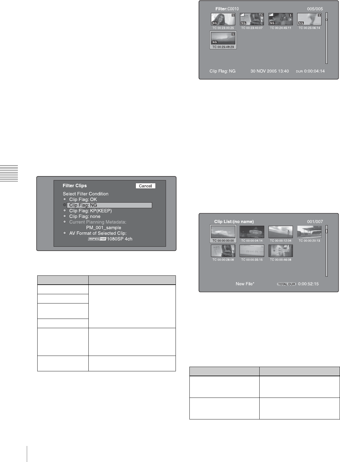
78 Thumbnail Operations
Chapter 5 Operations in GUI Screens
• Select clips in a certain video format from a disc that
contains clips in different video formats.
• Select clips that have been set “NG” as a clip flag, and
delete all of those clips in one operation.
• Select only clips that have been recorded on the basis of
a specified planning metadata entry, and transfer those
clips to an external device using the Direct FTP function.
To filter clips
See page 73 for more information about thumbnail screen
operations.
1
Display the clip thumbnail screen.
2
If you want to select clips by video format, select the
thumbnails of clips in that format.
3
Display the Thumbnail menu.
4
Select “Filter Clips”, and then press the PUSH
SET(S.SEL) knob.
The Filter Clips screen appears.
5
Select the clip filtering condition.
6
Press the PUSH SET(S.SEL) knob.
A filter thumbnail screen appears, showing only clips
that meet the specified condition.
The filtering condition appears at the lower left of the
screen.
7
If you want to filter the clips again with a different
filtering condition (to narrow down the filtering
results), repeat steps 2 to 6. (The command name
selected in step 4 changes to Filter Clips(Narrowing).)
To play selected clips continuously
Register all of the filtered clips in an automatically
generated clip list, and play the clip list.
1
Display the Thumbnail Menu in the filter thumbnail
screen.
2
Select “Copy to Clip List”, and then press the PUSH
SET(S.SEL) knob.
A clip list thumbnail screen appears, showing filtered
clips that have been registered in the clip list.
3
Press the PLAY button.
The screen changes to the clip playback screen, and
playback starts.
Operations on filtering results
You can use the Thumbnail Menu in the filter thumbnail
screen to perform the following operations.
Item name Filtering condition
Clip Flag: OK Clip flag set in the clip (OK/NG/
KP(KEEP)/none)
Clip Flag: NG
Clip Flag:
KP(KEEP)
Clip Flag: none
Current Planning
Metadata Clips that have been recorded
according to the instructions in the
currently loaded planning
metadata
AV Format of
Selected Clip Video format of the selected clips
Item name Function
Clip Information Select the information to be
displayed at the bottom of the
thumbnails.
Lock or Delete All Filtered
Clips >Lock All Filtered
Clips
Lock all of the filtered clips.
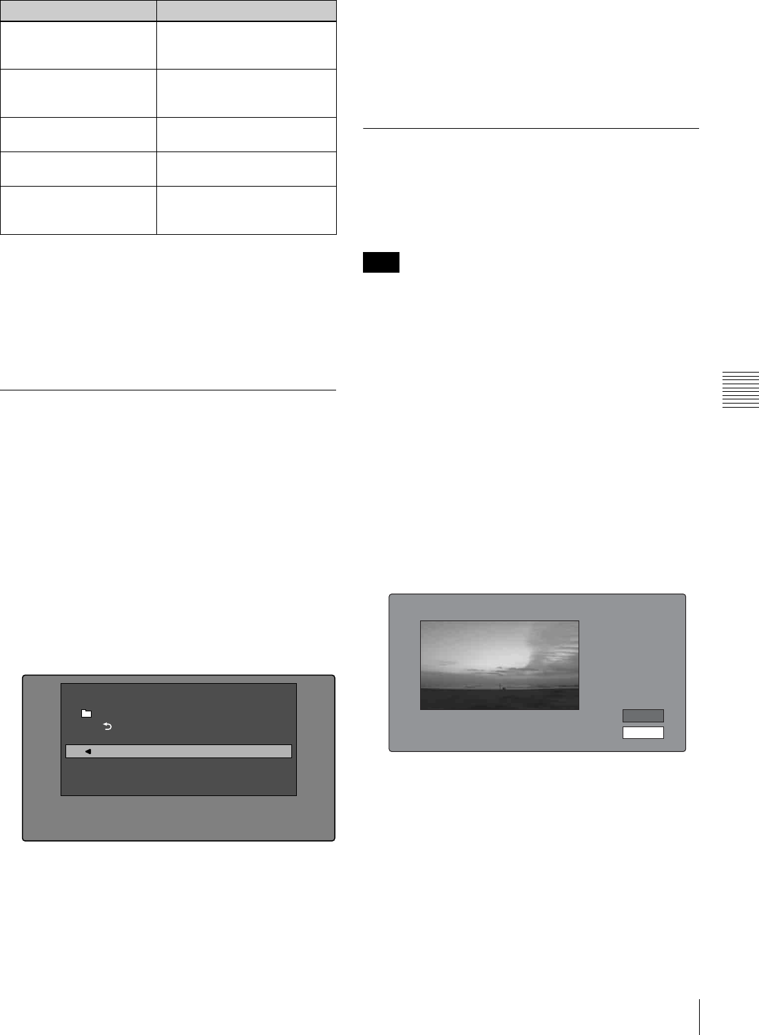
79
Thumbnail Operations
Chapter 5 Operations in GUI Screens
To display clip filtering conditions as Title2 titles
For clip lists created with the Copy to Clip List command,
you can display the clip filtering conditions as Title2 titles.
When Settings >Display Title in the Disc Menu is set to
"On: Title2 {title2}", the clip filtering conditions are
displayed automatically in screens such as the Load Clip
List screen.
Selecting the information displayed
on thumbnails
You can select the information to be displayed at the
bottom of the thumbnails in thumbnail screens.
See page 73 for more information about thumbnail screen
operations.
1
Display the Thumbnail Menu in the clip thumbnail
screen.
2
Select Clip Information.
A window appears in which you can select the
information to display.
3
Select the items that you want to display.
Date: Date and time of creation, or date and time of the
more recent modification
Time Code: Timecode of first frame
Duration: Playback time
Sequence Number: Thumbnail sequence number
Return to Upper Menu: Returns to the Thumbnail
Menu
The selected information will appear at the bottom of
the thumbnails when you display a thumbnail screen.
Changing clip index pictures
The clip thumbnail screen displays thumbnails as index
pictures for clips. Normally the index picture is the first
frame in a clip, but you can set any frame in the clip as the
index picture.
You can only change index pictures from the clip
thumbnail screen. The thumbnails shown in the clip list
thumbnail screen, the expand thumbnail screen, and the
chapter thumbnail screen cannot be changed.
To select a clip index picture while viewing the
video
See page 73 for more information about thumbnail screen
operations.
1
In the clip thumbnail screen, select the thumbnail of
the clip whose index picture you want to change.
2
Display the Thumbnail Menu.
3
Select Select Index Picture.
Select Index screen appears.
You can play and search with this screen.
4
Select a frame with the PLAY button or the jog dial.
5
Select OK, and then press the PUSH SET(S.SEL)
knob.
Lock or Delete All Filtered
Clips >Unlock All Filtered
Clips
Unlock all of the filtered clips.
Lock or Delete All Filtered
Clips >Delete All Filtered
Clips
Delete all of the filtered clips.
Filter Clips(Narrowing) Narrow down the filtering
results.
Copy to Clip List Copy all of the filtered clips to a
new clip list.
Upload Clips via Direct
FTP Transfer all of the filtered clips
to an external device via a
network.
Item name Function
Clip Information
Return to Upper Menu
Date
Time Code
Duration
Sequence Number
Thumbnail Menu
Note
Select Index:"Navigating sibling relati..." 018/036
TCR 01:09:16:13 OK
Cancel
80 Thumbnail Operations
Chapter 5 Operations in GUI Screens
To select index pictures by using the expand and
chapter functions
After using the expand function (see page 75) or chapter
function (see page 75) to find a frame, you can set that
frame as the index picture of the clip.
The following example explains how to do so from the
expand thumbnail screen.
See page 73 for more information about thumbnail screen
operations.
1
In the expand thumbnail screen, select the thumbnail
to set as the index picture.
2
Display the Thumbnail Menu.
3
Select Set Index Picture.
A message appears asking you to confirm that you
want to set the current frame as the index picture.
4
Select OK, and then press the PUSH SET(S.SEL)
knob.
After pressing the RESET/RETURN button to return
to the clip thumbnail screen, check to make sure that
the newly selected frame is displayed as the index
picture.
Checking clip properties
You can check clip properties such as the title, timecode,
duration, date and time of creation, and date and time of
the more recent modification.
See page 73 for more information about thumbnail screen
operations.
1
Display the Thumbnail Menu in the clip thumbnail
screen.
2
Select Clip Properties.
The Clip Properties screen appears.
Clip No.: Clip number/total number of clips
Name: Clip name 1)
Title1: Title1
Title2: Title 2 1)
AV Format: Recording format
TC: Timecode of first frame
DUR: Recording time
Created: Date and time of creation
Modified: Date and time of most recent modification
Rec Device: Name of device that created clip (product
number)
1)When the unit’s area of use (UC/J MODEL SELECT) (see page 33)
is set to “UC”, titles can be displayed in European languages.
To scroll hidden parts of the string into view
When a b or B mark is displayed for an item, you can
press the B/IN or b/OUT button to scroll the display
by one character for each press.
The V/MARK1 and v/MARK2 buttons scroll the
beginning and end of the string into view.
To display the properties of the previous or the
next clip
Press the PREV button or the NEXT button.
To return to the clip thumbnail screen
Press the PUSH SET(S.SEL) knob.
To edit clip information
You can edit the name, 1) title1, and title 2 of a clip by
using a software keyboard.
1) The “NAMING FORM” sub-item on setup menu item 036 must be set to
“free” (see page 125).
• The only characters that can be entered are the
alphanumeric characters and characters in the fonts
supported by this version of the unit’s firmware.
Japanese kanji cannot be entered.
• Names and titles must be within the specified character
length limits.
• Some symbols cannot be used in clip names. The keys
for those symbols are disabled when you are editing a
clip name.
Expand 001/012
TC 00:01:35:17
TC 00:01:37:11
TC 00:01:39:06
TC 00:01:37:24
TC 00:01:38:19
TC 00:01:36:14
TC 00:01:38:08
TC 00:01:40:02
TC 00:01:36:27
TC 00:01:38:22
TC 00:01:40:16
CLIP Tene DUR 0:00:00:13
TC 00:01:38:00 Set Index Picture
OK
Cancel
Notes
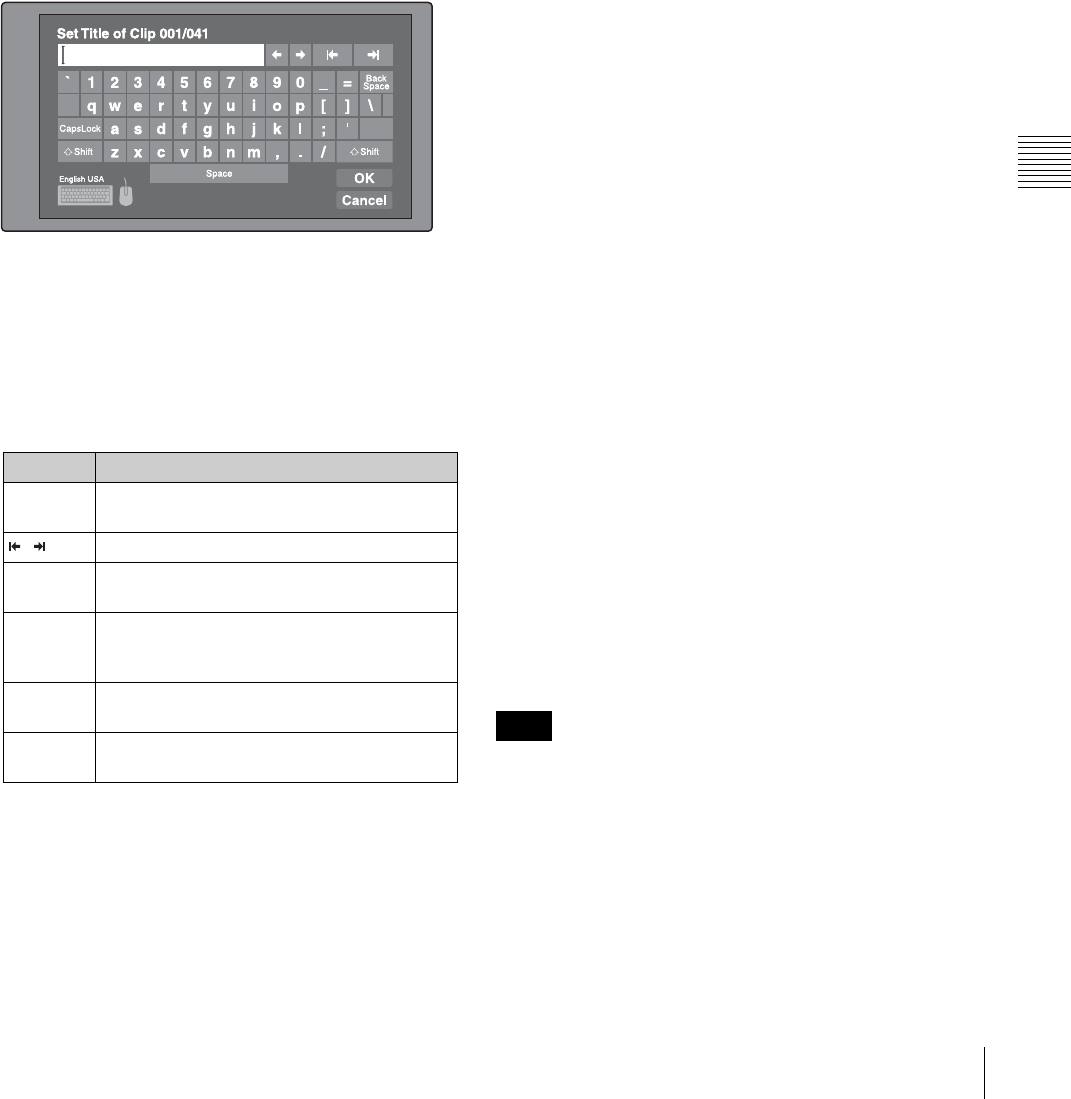
81
Thumbnail Operations
Chapter 5 Operations in GUI Screens
See page 73 for more information about GUI screen
operations.
1
In the Clip Properties screen, turn the PUSH
SET(S.SEL) knob to select the item you want to edit
(Name, Title1 1), or Title2).
1)Only ASCII characters can be used for Title1.
2
Press PUSH SET(S.SEL) knob.
An input screen appears for the selected item.
(If the area of use setting is “UC” (for regions outside
Japan), a keyboard appears that corresponds to the font
selected with Disc Menu item Settings >Select Font.)
A Japanese keyboard appears if the area of use setting
is “J” (for Japan).)
3
Edit the string in the edit box.
To enter characters
Use the V/MARK1, v/MARK2, B/IN or b/OUT
buttons or turn the PUSH SET(S.SEL) knob to select a
key, and then press the PUSH SET(S.SEL) knob.
Functions of special keys
4
Select OK, and then press the PUSH SET(S.SEL)
knob.
You return to the Clip Properties screen, and the
results of the editing are reflected in the clip
information.
To enter text using a USB keyboard or USB
mouse
You can connect a Windows USB keyboard or a Windows
USB mouse 1) to the MAINTENANCE connector (see
page 29), and use them together with the software
keyboard to enter text.
Connect a Japanese keyboard if you have set the area of
use to “J” (for Japan). 2)
Connect a keyboard that corresponds to the font selected
with Disc Menu item Settings >Select Font if you have set
the area of use to “UC” (for regions outside Japan).
1) Some USB keyboards or USB mice may not be recognized. In this case,
the message “Unknown USB” appears.
2) Only ASCII characters can be entered from a Japanese keyboard.
To change the display language (font) for clip names,
clip list names, and title2 clip titles: Select one of
the following languages (fonts) with the Disc menu
item Settings >Select Font.
• European Alphabet: The keyboard language can be
selected with the Disc Menu item Settings >USB
Keyboard Language (see following section).
• Korean: The Korean keyboard is selected
automatically. You can enter Hangul characters if
you have connected a Korean USB keyboard.
• Simplified Chinese: The keyboard layout is identical
to that of the English [United States] keyboard. Only
ASCII characters can be entered.
• Traditional Chinese: The keyboard layout is
identical to that of the English [United States]
keyboard. Only ASCII characters can be entered.
To change the keyboard language: Select the desired
language from the following values using Settings
>Select USB Keyboard Language in the Disc Menu.
• English [United Kingdom]
• English [United States]
• French [France]
• German [Germany]
• Italian [Italy]
• Polish (Programmers) [Poland]
• Russian [Russia]
• Spanish [Spain]
See “List of Supported USB Keyboards” (page 175) for
the characters that can be input in each language.
The keyboard language cannot be changed in the following
cases.
• When the area of use is set to “J” (for Japan).
• When the area of use is set to “UC” (for regions outside
Japan), and the Disc Menu item Settings >Select Font is
set to “Korean”, “Simplified Chinese”, or “Traditional
Chinese”.
Key Function
B, bMove the cursor one character forward or
back.
, Move the cursor to Home or End position.
Back
Space Deletes the character in front of the cursor.
CapsLock Turns the Shift key on permanently (until
pressed again), and enables input of capital
letters and symbols.
F Shift Enables input of capital letters and symbols.
Turns off after entry of one character.
Enter Confirms the edit and enables the OK and
Cancel buttons.
Note
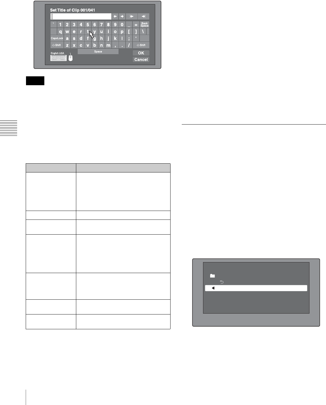
82 Thumbnail Operations
Chapter 5 Operations in GUI Screens
The keyboard icon on the software keyboard is highlighted
when a USB keyboard has been recognized and enabled
for use with this unit, and the mouse icon is highlighted
and a mouse pointer appears when a USB mouse has been
enabled.
• Use the proper keyboard for the area of use. Some
characters may not be entered correctly if you use a
keyboard designed for use in another area.
• It is not possible to enter Japanese, even on a Japanese
keyboard.
USB keyboard special functions keys
In addition to the special function keys of the software
keyboard, you can use the following special function keys
on a USB keyboard.
USB mouse functions
You can use the mouse to move the cursor on the software
keyboard. You can also left click on a key to enter the
character for that key.
To change the speed of the mouse pointer: Select the
desired speed using Settings >Select Mouse Pointer
Speed in the Disc Menu. Select the speed that works
best with the connected mouse.
To exit the software keyboard from a USB
keyboard
1
With the cursor in an edit box, press the Enter key to
move the focus to OK.
2
Do one of the following.
To confirm the edit and then exit the software
keyboard: While OK is selected, press the Enter
key.
To discard the edit and then exit the software
keyboard: On the USB keyboard, press the r key
or the Tab key to move to Cancel, and then press
the Enter key.
To continue editing: Press any key except the Enter
key, the Esc key, and the Tab key.
Setting clip flags
You can set three types of clip flags (OK/NG/KP (KEEP))
during recording or playback. Setting these flags in each
clip that you record makes it easy for editors and other
colleagues to find and select the clips that they need.
See page 73 for more information about thumbnail screen
operations.
1
In the clip thumbnail screen, select the thumbnail of
the clip where you want to set a flag.
2
Display the Thumbnail Menu.
3
Select Set Clip Flag.
The clip flag setting screen appears.
4
Select the clip flag that you want to set (OK/NG/KP
(KEEP)).
A clip flag icon (see page 68) appears for clips that
have clip flags set.
Notes
Key Function
V, vWhen the cursor is in an edit box:
Move the cursor to the start or
end.
When “OK” or “Cancel” has the
focus: Moves the focus between
“OK” and “Cancel”.
Delete Deletes the character after the cursor.
Shift + B, Shift + bSelects the string before or after the
cursor.
Ctrl + C, X, V, A, Z Ctrl + C: Copies the selected string.
Ctrl + X: Cuts the selected string.
Ctrl + V: Pastes a copied or cut string.
Ctrl + A: Selects the entire string.
Ctrl + Z: Undoes the immediately
preceding operation.
Enter When the cursor is in an edit box:
Moves the focus to OK.
When OK or Cancel has the focus:
Exits the software keyboard.
Esc When the cursor is in an edit box,
moves the focus to Cancel.
Tab Moves the focus between OK and
Cancel.
Thumbnail Menu
Set Clip Flag
Return to Upper Menu
OK
NG
KP (KEEP)
none

83
Thumbnail Operations
Chapter 5 Operations in GUI Screens
To clear clip flags
Carry out steps 1 to 3, selecting a clip that has a flag set,
and then select “none” in step 4.
You can also use CLIP FLG on page P7 OTHER of the
function menu to set and clear clip flags (see page 51).
Locking (write-protecting) clips
In a clip thumbnail screen, you can lock the selected clips
so that they cannot be deleted or altered.
Locking prevents the following operations on clips.
• Deletion
• Changing the index picture
• Adding and deleting shot marks
• Setting and clearing clip flags
• Locked clips are deleted along with other clips when a
disc is formatted.
• Clips cannot be locked or unlocked when the write
inhibit tab of the disc is set to the recording disabled
position, or when REC INH in the HOME page of the
function menu is set to ON.
To lock clips
See page 73 for more information about thumbnail screen
operations.
1
In the clip thumbnail screen, select the thumbnails of
the clips that you want to lock.
2
Display the Thumbnail Menu.
3
Select Lock/Unlock Clip.
4
Press the PUSH SET(S.SEL) knob.
A lock icon (see page 69) appears on the thumbnail of
the locked clips.
In step 1, you can also perform a shortcut operation by
pressing the STOP button with the SHIFT button held
down.
To lock all clips
1
Display the Disc Menu.
2
Select Lock or Delete All Clips, and then select Lock
All Clips.
A message appears asking you to confirm locking all
clips.
3
Select OK to lock all clips or Cancel to cancel it, and
then press the PUSH SET(S.SEL) knob.
To unlock a specific clip
See page 73 for more information about thumbnail screen
operations.
1
In the clip thumbnail screen, select the thumbnail of
the clip that you want to unlock.
2
Display the Thumbnail Menu.
3
Select Lock/Unlock Clip.
A message appears asking you to confirm the
unlocking.
4
Select OK, and then press the PUSH SET(S.SEL)
knob.
In step 1, you can also perform a shortcut operation by
pressing the STOP button with the SHIFT button held
down.
To unlock all clips
1
Display the Disc Menu.
2
Select Lock or Delete All Clips, and then select
Unlock All Clips.
A message appears asking you to confirm that you
want to unlock all clips.
3
Select OK to execute the unlock, or Cancel to cancel
it, and then press the PUSH SET(S.SEL) knob.
Deleting clips
You can delete clips while checking their contents.
• Clips cannot be deleted when the write inhibit tab of the
disc is set to the recording disabled position, or when
Notes
Notes
Clip List:E0001 002/013
TC 00:00:00:00
TC 00:00:28:08
TC 00:00:59:16
DATE&TIME 28 JUL 2006 19:55 TOTAL DUR 00:01:31:16
TC 00:00:04:14
TC 00:00:35:15
TC 00:01:06:18
TC 00:00:12:04
TC 00:00:46:08
TC 00:01:13:11
TC 00:00:20:13
TC 00:00:53:22
TC 00:01:17:27
Cancel
OK
Unlock Clip
Unlock this Clip?
C0004
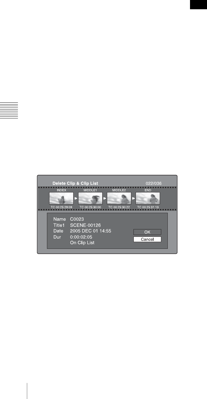
84 Thumbnail Operations
Chapter 5 Operations in GUI Screens
REC INH in HOME page of the function menu is set to
ON.
• Locked clips cannot be deleted.
• If a deletion target clips is referenced by clip lists on the
disc, all of those clip lists are deleted as well.
• If a deletion target clip is referenced in the current clip
list, only those referencing sub clips are deleted at the
same time as the deletion target clip.
See page 73 for more information about thumbnail screen
operations.
1
In the clip thumbnail screen, select the thumbnail of
the clip that you want to delete.
2
Display the Thumbnail Menu.
3
Select Delete Clip.
A window appears asking you to confirm the deletion.
The window displays thumbnails of four frames from
the target clip (the first frame, two intermediate
frames, and the last frame), along with the name, title1,
date of creation, and duration of the clip.
One of the following messages also appears,
depending on whether the clip is referenced in a clip
list.
•When the clip is not referenced in a clip list:
“Delete Clip”
•When the clip is referenced in a clip list: “Delete
Clip & Clip List” (All clip lists that reference the
target clip are deleted along with the clip.)
4
Select OK, and then press the PUSH SET(S.SEL)
knob.
The selected clip is deleted, and you return to the clip
thumbnail screen.
In step 1, you can also perform a shortcut operation by
pressing the RESET/RETURN button with the SHIFT
button held down.
To delete all clips
1
Display the Disc Menu.
2
Select Lock or Delete All Clips, and then select Delete
All Clips.
A message appears asking you to confirm that you
want to delete all clips.
3
Select OK to execute the deletion, or Cancel to cancel
it, and then press the PUSH SET(S.SEL) knob.
Locked clips cannot be deleted.
Note
85
Scene Selection (Clip List Editing)
Chapter 5 Operations in GUI Screens
Scene Selection (Clip List
Editing)
What is scene selection?
Scene selection is a function which allows you to select
material (clips) from the material recorded on a disc and
perform cut editing. You can do this by operating on this
unit only.
• Scene selection is a convenient way to perform cut
editing in the field and in other offline situations.
• In scene selection you create a clip list (editing data).
Since the material itself is not affected, you can repeat
this any number of times.
• You can play back the edit list created by scene selection
on this unit.
• In scene selection you can add whole clips or add parts
of a clip. You can add scenes using chapters, change the
playback sequence, and amend or delete In and Out
points. All of these operations can be carried out easily
on this unit.
• Clip lists (editing data) created with the scene selection
function can be used on XPRI and other full-feature
nonlinear editing systems.
Clips
Material recorded with this unit is managed in units called
clips. A clip contains the material from a recording start
point to a recording end point.
Clips have numbers beginning with C, for example C0001.
You can also assign titles to your clips and use the titles to
manage them, instead of the clip numbers. For more
information, “Assigning user-defined clip titles”
(page 107).
Clip lists
You can use the scene selection function to select clips
from the clips saved on a disc and create a cut edit list
called a “clip list”.
Clip lists have numbers beginning with E, for example
E0001. Up to 99 clip lists can be saved on a disc.
Sub clips (clips in clip lists)
Clips (or parts of clips) that have been added to a clip list
are called “sub clips”. Sub clips are virtual editing data that
specify ranges in the original clips. You can use them
without modifying the original data.
The following figure illustrates the relation between clips
and sub clips.
In the above example, the whole of clip 2 has been added
as sub clip 1, and the whole of clip 4 has been added as sub
clip 2.
Sub clip 3 is part of clip 3. Therefore, when clip list E0001
is played back, clip 4 is played after clip 2, and then the
part of clip 3 shown in gray color is played.
Clip list editing (current clip list)
To edit a clip list, you need to load the clip list from the
disc into the unit’s internal memory.
The clip list which is currently loaded into the unit memory
is called the “current clip list”.
The current clip list is always the target of sub clip creation
and editing. Clip list playback also uses the current clip
list.
After creating and editing a clip list, you need to save it to
disc.
Clip list playback
Clips and clip lists are saved together on a disc.
Recording
start point of
clip 2 Recording end
point of clip 2
Clip 1
(C0001) Clip 2
(C0002) Clip 3
(C0003) Clip 4
(C0004)
Unit memory
Current clip list
Can be edited (adding, deleting, and
reordering sub clips)
tClip list playback
and thumbnail
display
SAVE Mm LOAD
Disc
C0001 (Clip 1)
C0002 (Clip 2)
C0003 (Clip 3)
•
•
•
E0001 (Clip list 1)
E0002 (Clip list 2)
E0003 (Clip list 3)
•
•
•
E0099 (Clip list 99)
Clip 1
(C0001) Clip 2 (C0002) Clip 3
(C0003) Clip 4
(C0004)
Clip list (E0001)
Sub clip 1 Sub clip 2 Sub clip 3
Clips on disc
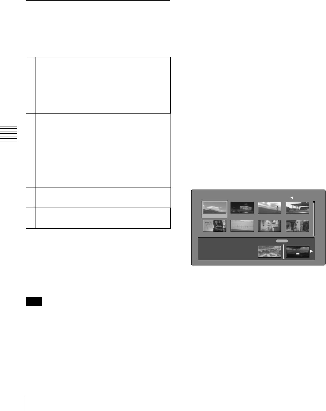
86 Scene Selection (Clip List Editing)
Chapter 5 Operations in GUI Screens
To play a clip list, insert a disc into the unit, load the clip
list that you want to play, and press the PLAY button.
Clips are played according to the data in the clip list.
Creating and editing clip lists
The following table lists the steps in the creation and
editing of clip lists with the scene selection function. To
create a clip list, you always need to carry out the steps
inside the heavy lines. Other steps can be carried out as
required.
To reedit clip lists on the disc
Use the Load Clip List command to load the clip lists you
want to edit, and perform the steps 2 to 4 in the previous
section.
You can also delete clip lists on the disc.
For details, see “Managing clip lists” (page 90).
Clip lists can be created and edited even when the write
inhibit tab of the disc is set to recording disabled, and when
REC INH on the HOME page of the function menu is set
to ON. However, if you need to save the clip list, set write
inhibit tab and REC INH to enable recording before you
create or edit the clip list.
To add sub clips
You can add sub clips to clip lists from with the clip
thumbnail screen or the clip list thumbnail screen.
However, you must use the clip list thumbnail screen to
edit clip lists.
Adding sub clips from the clip thumbnail screen
The following procedure explains operations in the clip
thumbnail screen. You can proceed in the same way in the
expand thumbnail screen and the chapter thumbnail
screen. Expanded blocks are added as sub clips in the
expand thumbnail screen, and chapters are added as sub
clips in the chapter thumbnail screen.
See page 73 for more information about thumbnail screen
operations.
1
In the clip thumbnail screen, select the clip that you
want to add as a sub clip (multiple selections possible).
2
Display the Thumbnail Menu.
3
Select Add Sub Clips, and then press the PUSH
SET(S.SEL) knob.
The Add Sub Clip screen appears.
The clip(s) selected in step 1 appear in the upper part
of this screen, and the clip list appears in the lower
Scene Selection window. The I cursor in the Scene
Selection window indicates the location where the
currently selected sub clip(s) will be inserted.
To display the total duration after addition of the
selected clip
Press the SHIFT button.
4
In the Scene Selection window, move the I cursor to
the location where you want to insert the clip. (The
existing thumbnails arrange themselves to the left and
right of the I cursor.)
5
Press the PUSH SET(S.SEL) knob.
The selected clip is inserted as a sub clip and a “+”
mark appears on the thumbnail in the Scene Selection
window.
1Add sub clips: Use the Add Sub Clips command to add
the clips you want to use to a clip list. You can add
up to 300 sub clips to one clip list.
This operation can be carried out in the following
thumbnail screens.
• Clip thumbnail screen
• Expand thumbnail screen
• Chapter thumbnail screen
• Clip list thumbnail screen
2Change the sub clip order: Use the Move Sub Clips
command to change the order of sub clips in a clip
list.
Delete sub clips: Use the Delete Sub Clips command
to delete specified sub clips from a clip list.
Trim sub clips: Use the Trim Sub Clip command to
adjust the In and Out points of a sub clip. This
function can also be used to adjust the overall
duration of the clip list.
Set the start timecode: Use the Set Start Time Code
command to set the timecode at the start of a clip
list.
3Play the clip list: Use the PLAY button and other
playback controls to play the current clip list and
check its contents.
4Save the clip list: Use the Save Clip List or Save Clip
List as… command to save the newly created clip
list to the disc.
Note
TOTAL 00:13:48:24
Add Sub Clip 017/035002
Scene Selection
TC 00:30:25:11
TC 00:24:24:29
TC 00:30:40:13
TC 00:24:34:27
TC 01:01:28:25
TC 00:24:46:22
TC 00:09:43:14
TC 00:24:56:24
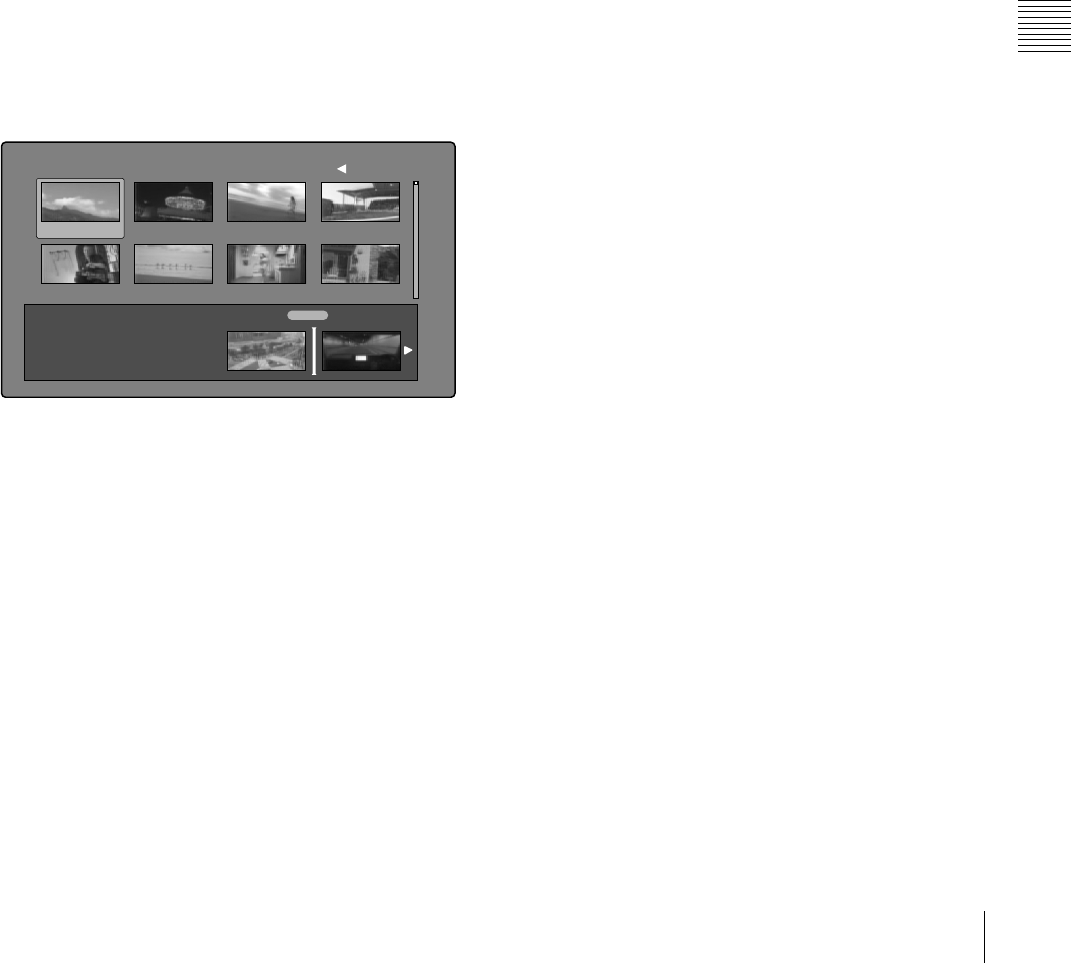
87
Scene Selection (Clip List Editing)
Chapter 5 Operations in GUI Screens
To check the addition results
Move the cursor.
6
Press the RESET/RETURN button.
This returns you to the Clip thumbnail screen.
7
Repeat steps 1 to 6 as required to add more clips.
8
Save the clip list (see page 90).
In step 1, you can hold down the SHIFT button when you
press the PUSH SET(S.SEL) knob. This is a shortcut that
displays the Add Sub Clip screen immediately. You can
also save the clip list immediately in step 5 by executing
the Save Clip List command in the Disc Menu.
Adding sub clips from the clip list thumbnail
screen
See page 73 for more information about thumbnail screen
operations.
1
Display the Thumbnail Menu.
2
Select Add Sub Clips, and then press the PUSH
SET(S.SEL) knob.
The Clip List (Add) screen appears.
3
Select the sub clips that you want to add from the
upper part of the screen (the part where 8 thumbnails
are displayed, multiple selections possible).
To select from expanded thumbnails
Press the EXPAND button to display the expand
thumbnail screen.
To select from chapter thumbnails
Press the CHAPTER button to display the chapter
thumbnail screen.
4
Press the PUSH SET(S.SEL) knob.
The thumbnail selection is confirmed, and an I cursor
appears at the bottom of the Clip List (Add) screen (in
the Scene Selection window). The I cursor indicates
the location where the currently selected sub clips will
be inserted.
To display the total duration after addition of the
selected clips
Press the SHIFT button.
5
In the Scene Selection window, move the I cursor to
the location where you want to insert the clip. (The
existing thumbnails arrange themselves to the left and
right of the I cursor.)
6
Press the PUSH SET(S.SEL) knob.
The sub clips are added at the I cursor position, and
you return to the clip list thumbnail screen.
You can check the results of the addition in that screen.
7
Repeat steps 1 to 6 as required to add more clips.
8
Save the clip list (see page 90).
In step 1, you can also perform a shortcut operation by
pressing the PUSH SET(S.SEL) knob with the SHIFT
button held down.
To add clips from the clip playback screen (quick
insertion)
This method allows you to decide the range to use and add
that range as a sub clip while viewing the video in the clip
playback screen. It does not use GUI screens. You can do
this during recording, playback (including pauses), and
searches.
1
Find the point that you want to make the start point of
the sub clip, and then press the PUSH SET(S.SEL)
knob with the B/IN button held down.
An In point is set and the IN indicator lights.
2
Find the point that you want to make the end point of
the sub clip, and then press the PUSH SET(S.SEL)
knob with the b/OUT button held down.
An Out point is set and the OUT indicator lights. (This
determines the range of the sub clip to be added.)
To check the timecode of the In point or Out point
Press the B/IN button or the b/OUT button.
To cue up the In point or Out point
Press the PREV button or the NEXT button with the
B/IN button or b/OUT button held down.
To check the duration (time from In point to Out
point)
Press the B/IN and b/OUT buttons at the same time.
TOTAL 00:13:48:24
Clip List (Add) 017/035002
Scene Selection
TC 00:30:25:11
TC 00:24:24:29
TC 00:30:40:13
TC 00:24:34:27
TC 01:01:28:25
TC 00:24:46:22
TC 00:09:43:14
TC 00:24:56:24
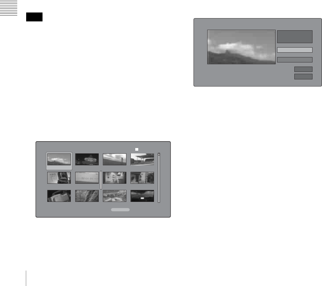
88 Scene Selection (Clip List Editing)
Chapter 5 Operations in GUI Screens
To delete the In point or Out point
Press the RESET/RETURN button with the B/IN or
b/OUT button held down.
3
With the SHIFT button held down, press the PUSH
SET(S.SEL) knob.
A sub clip with the range specified in steps 1 and 2 is
added to the end of the clip list.
When you specify a range that spans several clips
Sub clips are generated for each of the clips in the
range.
To check the newly added sub clips
You can check the newly added sub clips by
displaying the clip list thumbnail screen.
4
Repeat steps 1 to 3 as required to add more sub clips.
5
Save the clip list (see page 90).
To reorder sub clips
When this unit is in single clip playback mode (see
page 76), only the selected sub clip can be played.
See page 73 for more information about thumbnail screen
operations.
1
In the clip list thumbnail screen, select the thumbnails
of the sub clips that you want to move (multiple
selections possible).
2
Display the Thumbnail Menu.
3
Select Move Sub Clips, and then press the PUSH
SET(S.SEL) knob.
The Clip List (Move) screen appears.
4
Move the I cursor to the point where you want to move
the selected thumbnails.
5
Press the PUSH SET(S.SEL) knob.
The sub clips are moved to the I cursor position.
6
Repeat steps 1 to 5 as required.
7
Save the clip list (see page 90).
To adjust the In and Out points of sub clips
(trim)
Proceed as follows to define the range of a scene by
changing the positions of the In and Out points.
See page 73 for more information about thumbnail screen
operations.
1
In the clip list thumbnail screen, select a thumbnail.
2
Display the Thumbnail Menu.
3
Select Trim Sub Clip, and then press the PUSH
SET(S.SEL) knob.
The Clip List (Trim) screen appears.
Like the clip playback screen, this screen allows you to
play and search all clips on the disc.
To display a list of In and Out point operations that
you can perform
Press the MENU button.
4
When you find the point that you want to make the
start point, select “IN” and then press the PUSH
SET(S.SEL) knob.
The timecode of the new In point appears in the
timecode display, and the Total (total duration) and
DUR (clip duration) displays are updated.
5
When you find the point that you want to make the end
point, select “OUT” and then press the PUSH
SET(S.SEL) knob.
The timecode of the new Out point appears in the
timecode display, and the Total (total duration) and
DUR (clip duration) displays are updated.
Note
Clip List (Move) 001/034
TC 00:00:00:00
TC 00:04:35:12
TC 00:06:03:03
DATE&TIME 08 AUG 2007 11:50 TOTAL DUR 00:13:48:24
TC 00:00:21:27
TC 00:04:57:10
TC 00:06:25:00
TC 00:04:06:00
TC 00:05:19:08
TC 00:06:46:27
TC 00:04:13:14
TC 00:05:41:05
TC 00:07:08:25
006
Clip List (Trim) 001/034
TCR CLIP
01:17:33:08 019/035
01:17:33:08
Tot al
IN
00:13:48:24
DUR 00:00:21:27
OK
Cancel
01:17:55:05
OUT

89
Scene Selection (Clip List Editing)
Chapter 5 Operations in GUI Screens
To cue up the In point or Out point
Display the Thumbnail Menu, select Cue up Inpoint or
Cue up Outpoint, and then press the PUSH
SET(S.SEL) knob.
To cancel the In point or Out point setting
Display the Thumbnail Menu, select Reset Inpoint or
Reset Outpoint, and then press the PUSH SET(S.SEL)
knob.
The In point or Out point setting returns to the previous
value.
6
Select OK, and then press the PUSH SET(S.SEL)
knob.
7
Repeat steps 1 to 6 as required.
8
Save the clip list (see page 90).
To delete sub clips
See page 73 for more information about thumbnail screen
operations.
1
Select the clips to delete in the clip list thumbnail
screen (multiple selections possible).
2
Display the Thumbnail Menu.
3
Select Delete Sub Clips, and then press the PUSH
SET(S.SEL) knob.
A message appears asking you to confirm the deletion.
4
Select OK, and then press the PUSH SET(S.SEL)
knob.
5
Repeat steps 1 to 4 as required.
6
Save the clip list (see page 90).
To play the clip list
When this unit is in single clip playback mode (see
page 62), only the selected sub clip can be played.
See page 73 for more information about GUI screen
operations.
To play using GUI screens
1
In the clip list thumbnail screen, select the thumbnail
of the sub clip where you want to start play.
To start play from the start of the clip list
Select the thumbnail of the first sub clip.
2
Press the PUSH SET(S.SEL) knob.
To play using the clip list playback screen
1
Display the clip list playback screen.
2
Press the PREV button or the NEXT button to display
the sub clip that you want to play.
To start play from the first sub clip
Press the SHIFT + PREV buttons to move to the start
of the clip list.
3
Press the PUSH SET(S.SEL) knob.
To change the starting timecode of clip
lists
The timecode of clip lists is continuous timecode,
unrelated to the timecode of the original clips. By default
the timecode (LTC) of the start of the clip list is
00:00:00:00, but it can be set to any value.
See page 73 for more information about thumbnail screen
operations.
1
In the clip list thumbnail screen, display the
Thumbnail Menu.
2
Select Set Start Time Code, and then press the PUSH
SET(S.SEL) knob.
The Set Start Time Code screen appears.
3
Press the B/IN or b/OUT button to select the digit that
you want to change.
4
Turn the PUSH SET(S.SEL) konb or the jog dial to
change the value of the digit.
5
Repeat steps 3 and 4 as required.
Note
TC 22 : 34 . 56 : 17
Preset TC 00:00:00:00
OK
Cancel
Set Start Time Code
HMINSEC FRM

90 Scene Selection (Clip List Editing)
Chapter 5 Operations in GUI Screens
To reset the timecode to 00:00:00:00
Select Reset to Zero in the Thumbnail Menu, and then
press the PUSH SET(S.SEL) knob.
To preset the frequently used timecode
Select Save Preset TC in the Thumbnail Menu, and
then press the PUSH SET(S.SEL) knob.
The timecode set in steps 4 and 5 is saved as a preset
value.
To recall the preset timecode
Select Recall Preset TC in the Thumbnail Menu, and
then press the PUSH SET(S.SEL) knob.
6
Press the PUSH SET(S.SEL) knob.
OK is selected.
7
Press the PUSH SET(S.SEL) knob again.
8
Save the clip list (see page 90).
To save clip lists
To save under a specified name
See page 73 for more information about thumbnail screen
operations.
1
In the clip list thumbnail screen, display the Disc
Menu.
2
Select Save Clip List as..., and then press the PUSH
SET(S.SEL) knob.
A list of clip lists appears.
To switch the information displayed for clip lists
Press the b/OUT button.
With each press, the display changes in the order:
“Name & Date” >“Name & Title” >“Name & Sort
Date” >...
To sort clip lists
Select one of the following orders by selecting
Settings >Sort Clip List by... in the Disc Menu.
Name(A-Z): Sort in ascending order by clip list name.
Date(Newest First): Sort by date and time of clip list
creation, newest first.
3
Select the desired clip list name, and then press the
PUSH SET(S.SEL) knob.
To save under the same name
The following procedure saves the current clip list under
its current name (the name that appears in the clip list
thumbnail screen).
See page 73 for more information about thumbnail screen
operations.
1
In the clip list thumbnail screen, display the Disc
Menu (see page 72).
2
Select Save Clip List, and then press the PUSH
SET(S.SEL) knob.
The clip list is saved. However, Save Clip List as... is
executed when the name displayed in the clip list
thumbnail screen is “no name”.
If you press the EJECT button or the on/standby button
before saving a new or edited clip list, a message appears
asking if you want to discard your changes and continue.
Follow the instructions in the message to continue or
cancel the operation.
Managing clip lists
To load clip lists
The following procedure loads a clip list stored on the disc
into the unit’s internal memory as the current clip list.
See page 73 for more information about thumbnail screen
operations.
1
In the clip list thumbnail screen, display the Disc
Menu.
2
Select Load Clip List, and then press the PUSH
SET(S.SEL) knob.
A list of clip lists stored on the disc appears.
Save Clip List as...
E0003
E0004
E0005
E0006
E0007
E0095
E0098 Display Select
DVD og BI...
Name & Date/Sorted by Name
08 AUG2007 11:50
03 AUG2007 17:51
03 AUG2007 17:51
03 AUG2007 17:51
03 AUG2007 17:51
03 AUG2007 17:51
18 MAY2006 10:25
13 JUN2006 13:43
Disc Menu
Note

91
Scene Selection (Clip List Editing)
Chapter 5 Operations in GUI Screens
3
Select the desired clip list, and then press the PUSH
SET(S.SEL) knob.
The name of the clip list selected here appears in the
clip list thumbnail screen. When you execute the Save
Clip List command in the Disc Menu, the clip list will
be saved under that name.
To create a new clip list
Select New File and then press the PUSH SET(S.SEL)
knob.
To clear clip lists
The following procedure clears the current clip list from
the unit’s internal memory.
See page 73 for more information about thumbnail screen
operations.
1
In the clip list thumbnail screen, display the Disc
Menu.
2
Select Clear Clip List, and then press the PUSH
SET(S.SEL) knob.
A message appears asking you to confirm that you
want to clear the clip list.
3
Select OK, and then press the PUSH SET(S.SEL)
knob.
The current clip list returns to the unnamed state
“(no name)”.
To delete clip lists
The following procedure deletes a clip list from the disc.
See page 73 for more information about thumbnail screen
operations.
1
In the clip list thumbnail screen, display the Disc
Menu.
2
Select Delete Clip List, and then press the PUSH
SET(S.SEL) knob.
A list of clip lists appears.
3
Select the clip list that you want to delete, and then
press the PUSH SET(S.SEL) knob.
A message appears asking you to confirm the deletion.
4
Select OK, and then press the PUSH SET(S.SEL)
knob.
To sort clip lists
See page 73 for more information about thumbnail screen
operations.
1
In the clip list thumbnail screen, display the Disc
Menu.
2
Select Settings, and then press the PUSH SET(S.SEL)
knob.
3
Select Sort Clip List by..., and then press the PUSH
SET(S.SEL) knob.
4
Select one of the following sort methods, and then
press the PUSH SET(S.SEL) knob.
Name(A-Z): Sort in ascending order by clip list name.
Date(Newest First): Sort by date and time of clip list
creation, newest first.
Clip lists will be displayed in the specified order the
next time that you carry out an operation such as
loading a clip list.
Load Clip List
E0003
E0004
E0005
E0006
E0007
E0095
E0098 Display Select
DVD og BI...
Name & Date/Sorted by Name
08 AUG2007 11:50
03 AUG2007 17:51
03 AUG2007 17:51
03 AUG2007 17:51
03 AUG2007 17:51
03 AUG2007 17:51
18 MAY2006 10:25
13 JUN2006 13:43
Disc Menu
E0001
Delete this Clip List?
OK
Cancel
Delete Clip List
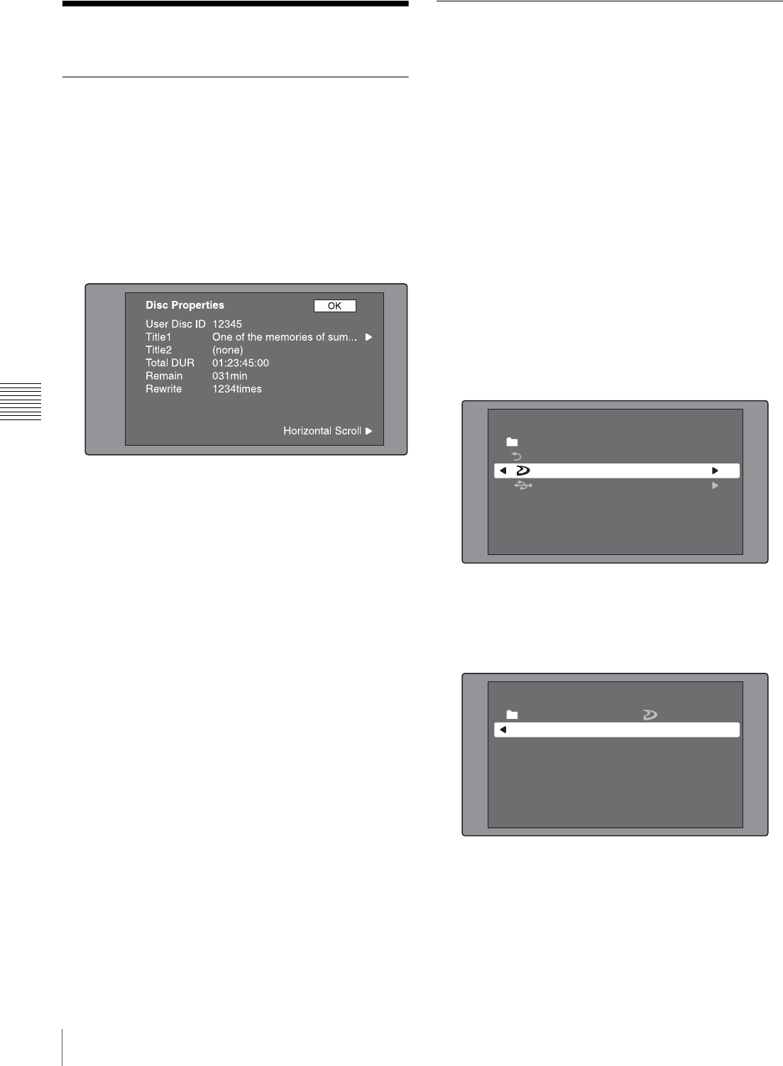
92 Disc Operations
Chapter 5 Operations in GUI Screens
Disc Operations
Checking disc properties
See page 73 for more information about GUI screen
operations.
1
Display the Disc Menu.
2
Select Disc Properties, and then press the PUSH
SET(S.SEL) knob.
The Disc Properties screen appears.
User Disc ID: User disc ID 1), 2)
Title1: Title1 1)
Title2: Title2 1), 2)
Total DUR: Total recording time
Remain: Remaining recording time
Rewrite: Number of times rewritten
1)This can be specified with the PDZ-1 Proxy Browsing Software on
the supplied XDCAM Application Software CD-ROM.
2)When the unit’s area of use (UC/J MODEL SELECT) (see page 33)
is set to “UC”, titles can be displayed in European languages.
To scroll hidden parts of the string into view
When a b or B mark is displayed for an item, you can
press the B/IN or b/OUT button to scroll the display
by one character for each press.
The V/MARK1 and v/MARK2 buttons scroll the
beginning and end of the string into view.
To return to the previous screen
Press the PUSH SET(S.SEL) knob.
To edit disc information
You can edit the user disc ID, title11), and title2 by using a
software keyboard.
1) Only ASCII characters can be used for the title1.
See “To edit clip information” (page 80) for more
information about operations.
Using planning metadata
Planning metadata is a file that contains metadata about the
clips to be shot and recorded.
To use planning metadata, you will need to save a file in
advance in the specified location of a media, and insert the
media into this unit.
See “To set clip names by using planning metadata”
(page 151) for details.
To load planning metadata files
See page 73 for more information about GUI screen
operations.
1
Display the Disc Menu.
2
Select Load Planning Metadata/Select Drive, and then
press the PUSH SET(S.SEL) knob.
A media selection screen appears.
3
Select the media where your planning metadata file is
stored, and then press the PUSH SET(S.SEL) knob.
A list of the planning metadata files stored on the
media appears.
4
Select the desired planning metadata file, and then
press the PUSH SET(S.SEL) knob.
The selected planning metadata file is loaded into the
unit’s memory, and the Planning Metadata Properties
screen appears.
Disc Menu
Load Planning Metadata/Select Drive
Professional Disc
USB Flash Drive
Return to Upper Menu
Disc Menu
Load Planning Metadata/
PM_001_sample
04 AUG 10:39
04 AUG 10:39
Professional Disc
PM_002_sample
04 AUG 10:39
PM_003_sample
04 AUG 10:39
Name &Date/ Sorted by Name
PM_004_sample
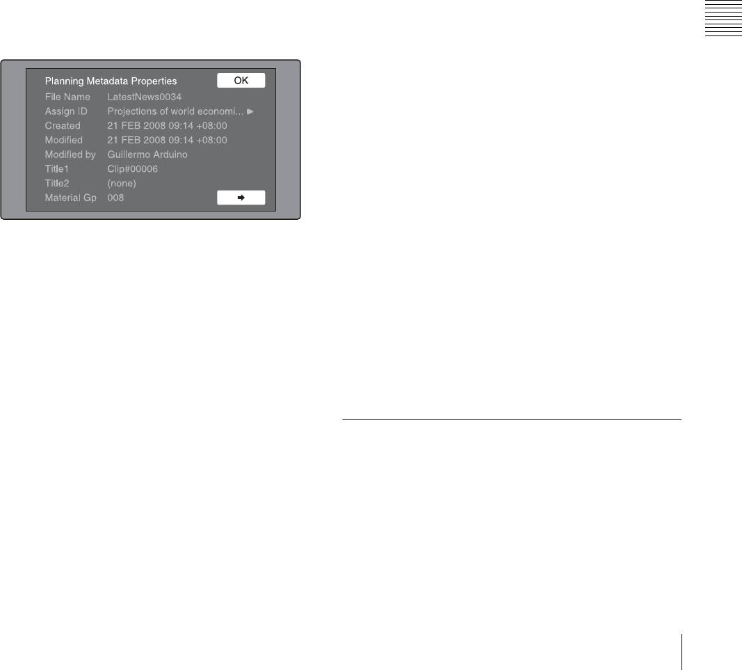
93
Disc Operations
Chapter 5 Operations in GUI Screens
5
Check the information that appears, and press the
PUSH SET(S.SEL) knob.
To sort planning metadata
You can sort planning metadata by operating in the same
way as in “To sort clip lists” (page 91). However, in step
3, select Sort Planning Metadata by....
The planning metadata will be displayed in the specified
order the next time you load planning metadata.
To check planning metadata properties
You can check the properties of the planning metadata that
is loaded into this unit’s memory, including the date and
time of creation and the clip titles.
See page 73 for more information about GUI screen
operations.
1
Display the Disc Menu.
2
Select Planning Metadata Properties, and then press
the PUSH SET(S.SEL) knob.
The Planning Metadata Properties screen appears.
File Name: Planning metadata file name
Assign ID: Assign ID
Created: Date and time of creation
Modified: Date and time of most recent modification
Modified by: Name of person who modified the file
Title1: Title 1 1)
Title2: Title 2
Material Gp: Material group name
1)This can be set as the clip name (see page 151).
To scroll hidden parts of the string into view
When a b or B mark is displayed for an item, you can
press the B/IN or b/OUT button to scroll the display
by one character for each press.
The V/MARK1 and v/MARK2 buttons scroll the
beginning and end of the string into view.
To return to the previous screen
Press the PUSH SET(S.SEL) knob.
To clear planning metadata
See page 73 for more information about GUI screen
operations.
1
Display the Disc Menu.
2
Select Clear Planning Metadata, and then press the
PUSH SET(S.SEL) knob.
A message appears asking if you are sure that you want
to clear the plannning metadata.
3
Select OK, and then press the PUSH SET(S.SEL)
knob.
The planning metadata is cleared from this unit’s
memory.
To switch the title display in the display
window
When planning metadata is loaded into this unit, you can
select the format of the title to display in the display
window.
See page 73 for more information about GUI information.
1
Display the Disc Menu.
2
Select Settings, and then press the PUSH SET(S.SEL)
knob.
3
Select Planning Clip Name in Clip Info. Area and then
press the PUSH SET(S.SEL) knob.
See page 24 for more information about the clip
information area.
4
Select one of the following, and then press the PUSH
SET(S.SEL) knob.
Off: Do not display a title.
ASCII Clip Name: Display the ASCII format title
(see page 151)
Clip Name: Display the UTF-8 format title (see
page 151)
Checking user-defined essence
marks
You can display the names of user-defined Shot Mark0 to
Shot Mark9 essence marks in planning metadata (UTF-8
format, maximum 32 bytes).
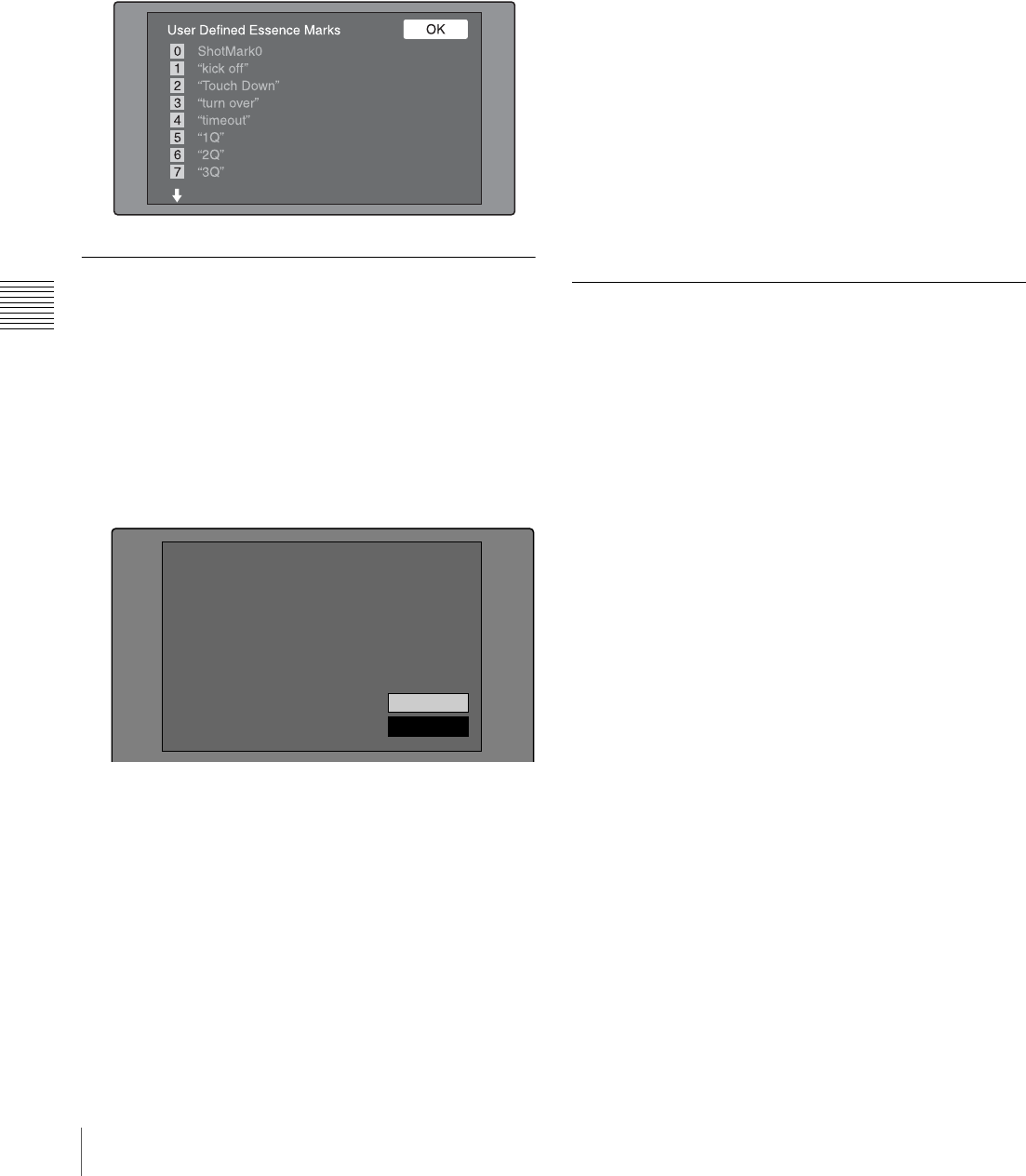
94 Disc Operations
Chapter 5 Operations in GUI Screens
1
Display the Planning Metadata Properties screen (see
page 93) for the planning metadata loaded into this
unit.
The , button is enabled when the planning metadata
contains user-defined essence marks (see page 152).
2
Press ,, and then turn the PUSH SET(S.SEL) knob.
The User Defined Essence Marks screen appears.
Formatting discs
See page 73 for more information about GUI screen
operations.
1
Display the Disc Menu.
2
Select Format Disc, and then press the PUSH
SET(S.SEL) knob.
A message appears asking you to confirm the format.
3
Select OK, and then press the PUSH SET(S.SEL)
knob.
To cancel the format
Select Cancel, and then press the PUSH SET(S.SEL)
knob.
To continue by formatting another disc
Exchange the disc, select OK, and then press the
PUSH SET(S.SEL) knob.
To exit the formatting screen
Press the PUSH SET(S.SEL) knob with Exit selected.
To disable the Format Disc command
To prevent inadvertent disc formatting, resulting in the
loss of recorded data, you can disable the Format Disc
command.
See page 73 for more information about GUI information.
1
Display the Disc Menu.
2
Select Settings, and then press the PUSH SET(S.SEL)
knob.
3
Select Disable “Format Disc”, and then press the
PUSH SET(S.SEL) knob.
4
Select Disable, and then press the PUSH SET(S.SEL)
knob.
Displaying disc and clip properties
in a web browser
By connecting this unit and a computer over a network,
you can display disc properties and clip properties in a web
browser installed on the computer (Web Thumbnail
function).
The Clip Properties page also allows you to download
high-resolution clip data, proxy AV data, and metadata
from this unit and to save that data on your computer.
To display the unit’s XDCAM web pages
1
Connect this unit and a computer to a network (see
page 149).
2
Start the browser on the computer, and enter “http://”
+ IP_address_of_this_unit + “/” in the address bar of
the browser, and then press the Enter key.
For example, if the IP address of this unit is
“192.168.001.010”, enter “http://192.168.1.10/”.
If the connection succeeds, you will be prompted to
enter a user name and a password.
3
Enter your user name and password, and then press the
Enter key.
The user name and password are set to the following
when the unit is shipped from the factory.
• User name: admin
• Password: Model name (“pdw-f1600” or “pdw-
hd1500”)
Cancel
OK
Format Disc
All Clips, Clip Lists and
Non-AV Data (General Files)
will be Deleted.
Format OK?
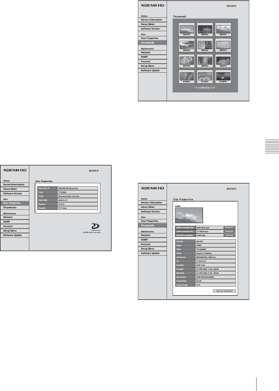
95
Disc Operations
Chapter 5 Operations in GUI Screens
After the user name and password are verified, an
XDCAM web page appears.
To display disc and clip properties
1
Insert a disc into this unit, and put this unit into the
following state.
• Recording, playback, search and other disc
operations: Stopped
• THUMBNAIL button: Off
• Disc access by Lock or Delecte All Clips, Format
Disc, and so on in the Disc Menu: Stopped
• FAM or FTP connection for file operations:
Disconnected, or logged out
2
Display the XDCAM web pages in the browser of your
computer (see the previous section).
To display disc properties
Click “Disc Properties” in the Disc menu.
The disc properties of this unit appear in the Disc
Properties page.
See “Checking disc properties” (page 92) for more
information about the various properties.
To display clip thumbnails
Click “Thumbnails” in the Disc menu.
A page of thumbnails of clips on the disc appears.
Each thumbnail page displays up to 12 thumbnails.
When multiple pages exist, you can switch pages by
clicking << (back five pages), < (back one page), >
(forward one page), or >> (forward five pages).
To display clip properties
In the Thumbnails page, select a clip by clicking its
thumbnail.
The properties of that clip appear in the Clip Properties
page.
See “Checking clip properties” (page 80) for more
information about the various properties.
To download high-resolution clip data (HIGH
resolution file), proxy AV data (LOW resolution file),
or metadata (Clip NRT metadata), click the Download
button to the right of the item that you want. Then click
“Save” in the dialog that appears and specify the save
destination.
The specified data is downloaded to the specified
location in your computer.

96 Disc Operations
Chapter 5 Operations in GUI Screens
• The characters that can be used in the names of clip-
related data files are single-byte letters, numbers,
and symbols. However, the following symbols
cannot be used.
" # * / : < > ? \ |
• If you click “Cancel” in the download dialog, or if
the download is cancelled in some other way with
the browser still connected to the unit by FTP, click
“Back to Thumbnails” to return to the thumbnails
screen, or exit the web browser.
Notes
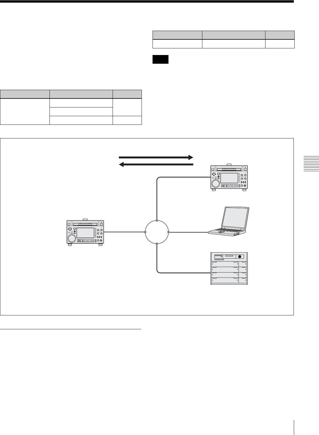
97
Transferring clips (Direct FTP function)
Chapter 5 Operations in GUI Screens
Transferring clips (Direct FTP function)
You can transfer clips (MXF files) between this unit and
external devices over a network. This unit has an Direct
FTP function, which allows you to connect to any
XDCAM device or computer with an FTP server function
and transfer files with a few simple operations in the GUI
screen.
The following table lists the types of file transfers that this
unit can execute.
File transfers with this function are limited to clips (high-
resolution data) and clip list files. To transfer files of other
types (proxy AV data, files in the General and User Data
directories, and so on), operate after establishing a FAM or
FTP connection (see page 104).
Preparations for clip transfers
Check the following points.
• This unit must be connected over a network to the
transfer target device (XDCAM device or computer).
• The settings under maintenance menu item M5:
NETWORK must be set to values that allow network
connections.
• The remote control switch must be set to NET.
• For XDCAM devices that support UPnP (universal plug
and play), the UPnP function must be enabled (the
setting may vary).
To enable the UPnP function
The UPnP (universal plug and play) function allows
devices to be easily connected to networks. The following
XDCAM devices support UPnP.
• PDW-F1600
• PDW-HD1500
•PDW-F800
Transfer direction Transfer target Function
Upload One or more clips put
Multiple clips with clip list
Part of one clip partial put
Download One clip get
Note
Transfer direction Transfer target Function
Upload clip (put)
Download clip (get)
a) The following software requirements must be satisfied.
• An FTP server function must be available.
• In the case of Windows, Microsoft Window IIS (Internet Information
Service) Version 7.0 or higher.
• In the case of Macintosh, Mac OS X Version 10.5.6 or higher.
Network
Local host (this unit)
PDW-HD1500
Laptop computer a)
Material server
Remote server
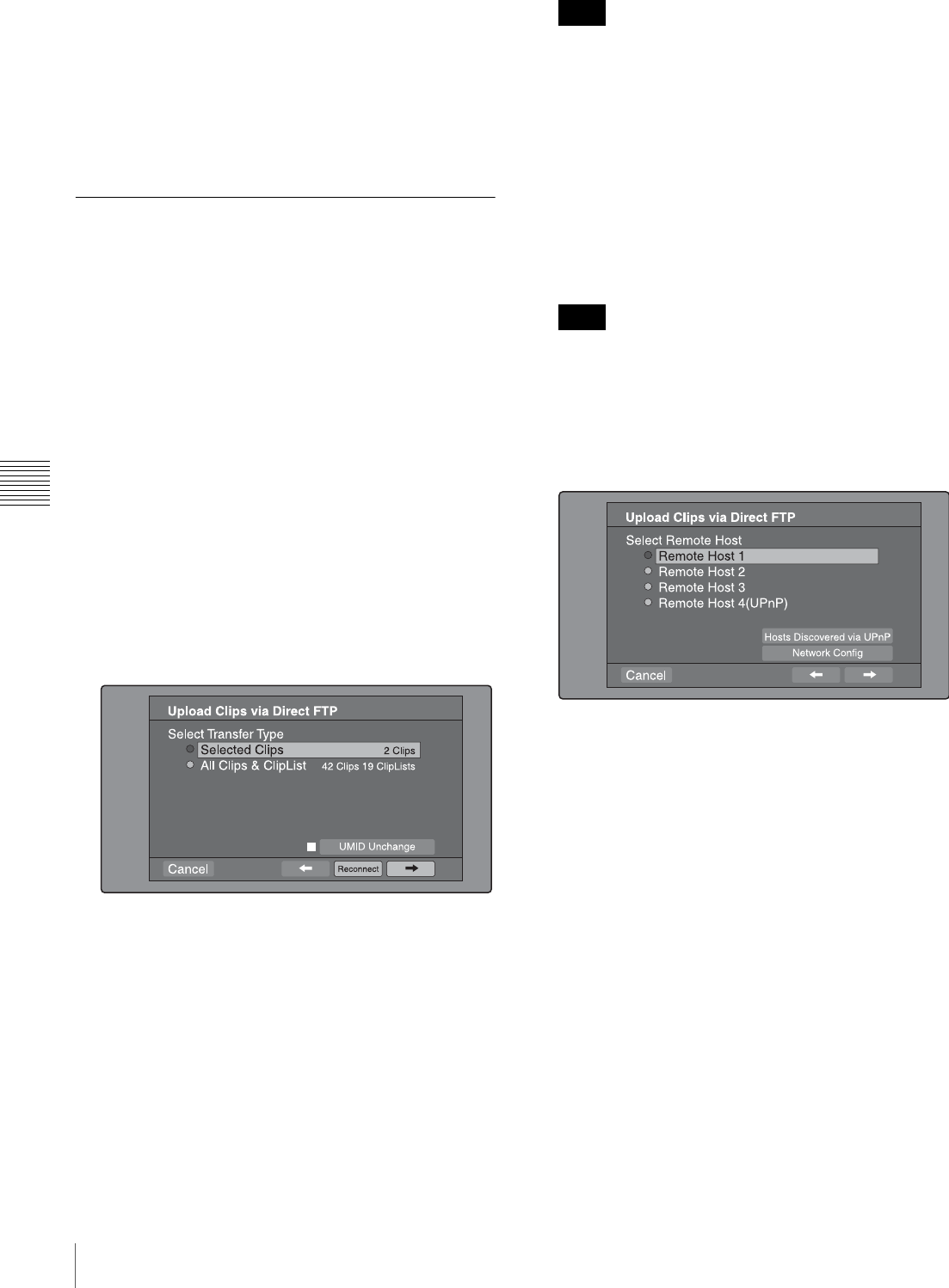
98 Transferring clips (Direct FTP function)
Chapter 5 Operations in GUI Screens
• PDW-700
• PDW-740
To enable the UPnP function on this unit, set maintenance
menu item M59: UPnP to ENABLE.
For the settings on other XDCAM devices, refer to the
operation manuals supplied with the devices.
Uploading clips
To upload entire clips
Proceed as follows to upload selected clips or all clips and
clip lists on the disc.
See page 73 for more information about thumbnail screen
operations.
1
In the clip thumbnail screen, select the clip to upload
(multiple selections possible).
To upload all clips and clip lists on the disc, start from
step 2.
2
Display the Thumbnail Menu.
3
Select Upload Clips via Direct FTP, and then press the
PUSH SET(S.SEL) knob.
The Select Transfer Type screen of the Upload Clips
via Direct FTP command appears.
4
Select the type of clip transfer.
Selected Clips: Clips selected in step 1.
All Clips & ClipList: All clips and clip lists on the
disc.
To transfer while preserving the UMID of the
transfer source clips
Check the “UMID Unchanged” option.
If the remote host is a computer, clips are transferred
with the UMID unchanged regardless of this setting.
To reconnect to a remote host
The Reconnect button is enabled if the most recent
operation successfully established a connection to a
remote host.
You can select “Reconnect” and press the PUSH
SET(S.SEL) knob to reconnect to that host. The host is
selected automatically and the screen changes directly
to the Connecting Status screen (see step 9 in the
procedure).
The Reconnect button is not enabled if the most recent
operation failed to connect to a remote host.
5
Select ,, and then press the PUSH SET(S.SEL)
knob.
The Select Remote Host screen appears.
6
Select the remote host (the target device to which you
want to transfer the clips).
You can register up to four remote hosts.
Remote Host 1 to 3: Register these in the settings
screen.
Remote Host 4(UPnP): A remote host that supports
UPnP (universal plug and play) is detected and
registered automatically (see “To enable the
UPnP function” (page 97)).
To check remote hosts discovered by the UPnP
function
Select “Hosts Discovered via UPnP”, and then press
the PUSH SET(S.SEL) knob. (If the UPnP function of
this unit is disabled, a confirmation screen appears
prompting you to enable it. Select “OK” and then press
the PUSH SET(S.SEL) knob.
The Select Host Discovered via UPnP screen appears.
(Some time may be required before the search for
remote hosts finishes.)
Select the name of a remote host from the list, and
press the PUSH SET(S.SEL) knob. A network settings
Note
Note
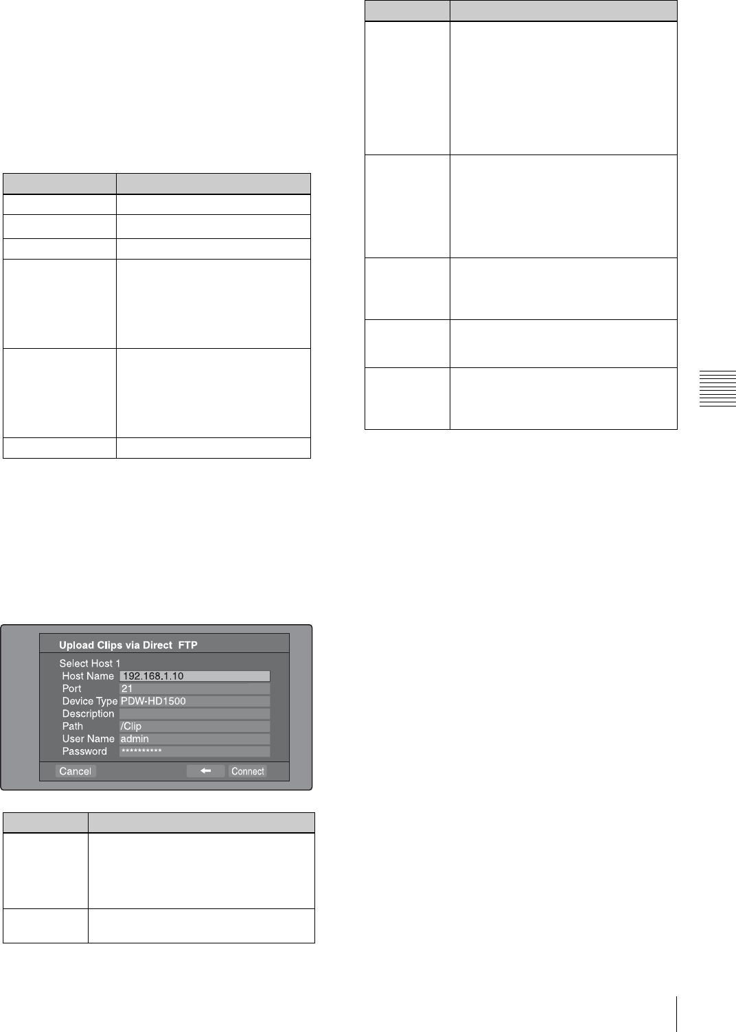
99
Transferring clips (Direct FTP function)
Chapter 5 Operations in GUI Screens
screen appears (see step 7). If you establish a
connection with the selected remote host, the network
settings are saved in Remote Host 4. From the next
time that you select “Remote Host 4(UPnP)”, the
remote host that you select here will be connected.
To check the network settings of this unit
Select “Network Config”, and then press the PUSH
SET(S.SEL) knob. The following network settings
appear.
a) An IP address determined by a DHCP server appears instantly in this
field.
Select OK and press the PUSH SET(S.SEL) knob to
return to the previous screen.
7
Select ,, and then press the PUSH SET(S.SEL)
knob.
A network settings screen for the remote host appears.
a) If an XDCAM device is selected as the Device Type, then the User
Name and Password are set automatically to the default, and you do
not need to make the Port and Path settings. Simply selecting the
Host Name (or as appropriate the Description) is enough to fulfill the
requirements for connection.
If the User Name or Password of the device that you
want to connect to changes, set them here.
8
Set the various items.
To select an item
Turn the PUSH SET(S.SEL) knob to move the cursor,
and then push the PUSH SET(S.SEL) knob.
A software keyboard appears so that you can enter a
setting.
9
Select “Connect”, and then press the PUSH
SET(S.SEL) knob.
The settings are saved and the Connecting Status
screen appears.
Item Setting
Host Name Host name
IP Address IP address a)
Subnet Mask Subnet mask
DHCP Setting that specifies whether to
acquire the IP address
automatically from a DHCP server
Enabled: Acquire automatically
Disabled: Do not acquire
automatically
Address Status Method used to set IP address
Manual Set: Manually
DHCP: DHCP function
AutoIP: Auto IP addressing
function
Undefined: Nothing specified
Default Gateway Default gateway
Item Setting
Host Name Host name or IP address. (If this is a
host name, a DNS server must be
available on the connected network.
Specification of an IP address is
recommended.)
Port Port used by the FTP server (normally
“21”).
Device Type The type of the remote host
• If the remote host is an XDCAM
device, select the model name or
“Other XDCAM model” (if the model
name is not in the list) from the list of
model names. a)
• If the remote host is a computer,
select “Others(PC Server)” from the
list of model names.
Description Comment about the remote host. (UTF-
8 encoding, up to 128 characters. This
setting has no effect on the connection.)
The setting that you make here appears
as the remote host name in the Select
Remote Host screen (see step 5 of the
procedure).
Path If the remote host is a computer, path to
the transfer destination directory. (This
is not needed if the remote host is an
XDCAM device.)
User Name User name for FTP login. (If the remote
host is an XDCAM device, the default is
“admin”.)
Password Password for FTP login. (If the remote
host is an XDCAM device, the default is
the model name, such as “pdw-
hd1500”.)
Item Setting
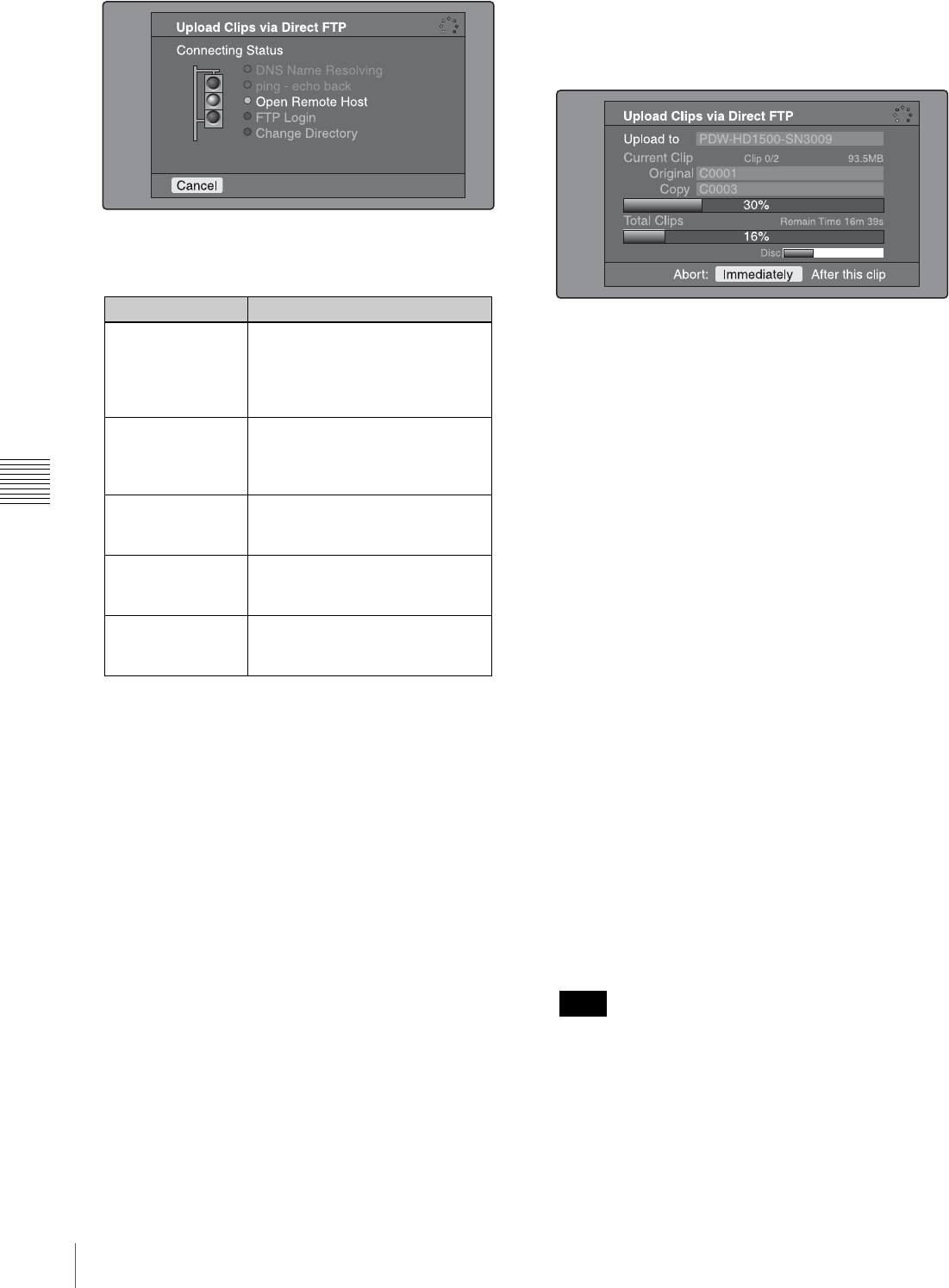
100 Transferring clips (Direct FTP function)
Chapter 5 Operations in GUI Screens
The following table lists the various stages that appear
in the connection status screen and describes the
corresponding processing.
The status indicated beside each item lights in yellow
during processing for that item, and lights in green
when the processing finishes.
If an error occurs
The status indicator changes to red.
Correct the condition that caused the error and repeat
the operation.
If you cannot connect
Check the following points.
• Make sure that this unit and the remote host are
correctly connected to the network.
• If the remote host is an XDCAM device, make sure
that it is not displaying a GUI screen.
• If the remote host is an XDCAM device, make sure
that a disc is inserted.
When the connection is complete (the indicators of all
items have turned green), the Upload Clips via Direct
FTP screen appears.
To check the connection on the remote host side
If the remote host is an XDCAM device, check that the
“NETWORK!” has appeared in the display or other
status display location.
The progress bars show the progress of the transfer. If
multiple clips are being transferred, a count of the clips
that have been successfully transferred appears.
If the remote host is an XDCAM device, the disc usage
also appears. (It does not appear if the remote host is a
computer).
If a file of the same name already exists at the
transfer destination
The file name is changed so that it does not conflict
with the file at the destination.
The name of the file on the transfer source (this unit)
appears in the “Original” field, and the name of the file
on the transfer destination appears in the “Copy”
field. 1)
1) If the clip name is a standard name, it is changed to the unused clip
name with the smallest number. (Example: If names C0001 to C0020
are in use, the name C0021.)
If the clip name is a user-defined name, a serial number is appended
to the clip name. (Example: If the name is EveningNews,
EveningNews(1).)
To cancel the processing
Do one of the following.
• Select “Abort: Immediately”, and then press the
PUSH SET(S.SEL) knob.
• If you are transferring multiple clips, select “Abort:
After this clip”, and then press the SET/S.SEL
button or the MENU knob. (The transfer of
subsequent clips will be cancelled after transfer of
the current clip finishes.)
• Set the remote control switch of the unit to
“LOCAL”.
When several files are to be transferred, the entire
transfer task is cancelled when the first transfer failure
occurs. Subsequent clips are not transferred.
When the transfer of all files has finished, the
Uploading Result Report screen appears.
Press the PUSH SET(S.SEL) knob. This returns you to
the clip thumbnail screen.
Item Description
DNS Name
Resolving When host was specified by a
host name instead of an IP
address, the unit is querying a
DNS server for the host’s IP
address.
ping - echo back The unit has issued a ping
(communications established)
command and is waiting for a
response.
Open Remote Host The unit is connecting to the
remote host over the specified
port.
FTP Login The unit is logging in to the
remote host with specified user
name and password.
Change Directory When a path was specified, the
unit is changing to the specified
directory.
Note
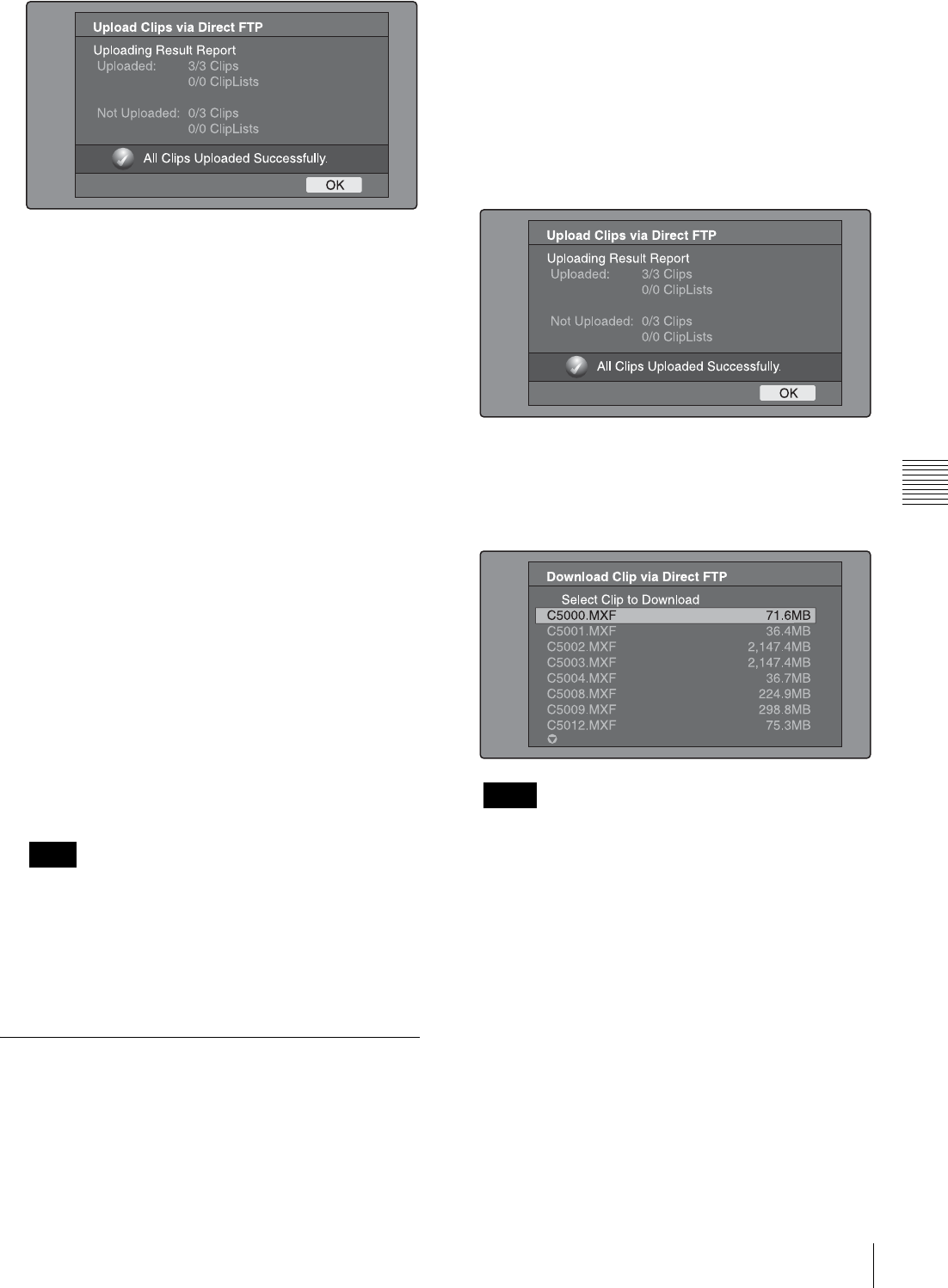
101
Transferring clips (Direct FTP function)
Chapter 5 Operations in GUI Screens
To upload part of a clip
You can select part of a clip in the expand thumbnail
screen or the chapter thumbnail screen and upload that
part.
Expand thumbnail screen: The clip is divided arbitrarily
into parts of equal length, regardless of content. Use
this method if you do not need to specify the transfer
range precisely.
Chapter thumbnail screen: Use this method if you want
to transfer a specific range. (By setting essence marks
at the start point and end point of the transfer range,
you can specify the range with a precision of one
frame.)
1
In the clip thumbnail screen, select a clip and press the
EXPAND or CHAPTER button.
The expand thumbnail screen or the chapter thumbnail
screen appears.
2
Select the transfer range.
To select multiple thumbnails
While holding the SHIFT key down, turn the PUSH
SET(S.SEL) knob, or press the B/IN or b/OUT button.
The duration of the transfer range appears in the lower
right of the screen.
When the selected range (duration) in the expand
thumbnail screen is less than two seconds, it is
expanded automatically to two seconds.
3
Execute step 2 to 9 of the previous section “To upload
entire clips”.
Downloading clips
Proceed as follows to download clips from a remote host
(such as other XDCAM device devices or a material
server).
See page 73 for information about thumbnail screen
operations.
1
Display the Disc Menu.
2
Select Download Clip via Direct FTP, and then press
the PUSH SET(S.SEL) knob.
The Select Remote Host screen of the Download Clip
via Direct FTP command appears.
3
Execute steps 6 to 9 of “To upload entire clips”
(page 98).
If the connection succeeds, the Select Clip to
Download screen appears.
• If the remote host is a computer, only the MXF files
in the specified directory appear.
• File names containing other than ASCII characters
(kanji and so on) are not displayed.
4
Select a clip to download, and then press the PUSH
SET(S.SEL) knob.
The download starts.
When the download finishes, the Downloading Result
Report screen appears.
Select “OK”, and then press the PUSH SET(S.SEL)
knob. This returns you to the clip thumbnail screen.
Note
Notes
102 Transferring clips (Direct FTP function)
Chapter 5 Operations in GUI Screens
Copying clips directly between
XDCAM devices
In the field or another environment where the devices are
not connected to a network, you can copy (upload) clips
between XDCAM devices by connecting them directly.
The example in the following procedure shows how to
copy a clip from this unit to a PDW-HD1500. Insert discs
into both units and proceed as follows.
1
Connect this unit and the PDW-HD1500 by a network
cable.
The cable can be either a cross cable or a straight cable.
2
Set up the two units as follows.
3
Power both units off and on again, and wait for about
three minutes.
4
Check that the IP addresses of the two units have been
set as follows by the Auto-IP function.
5
In the clip list thumbnail screen of this unit, select the
clip to copy (upload).
6
Display the Thumbnail Menu.
7
Select Upload Clips via Direct FTP, and then press the
PUSH SET(S.SEL) knob.
With , selected, the Select Transfer Type screen of
the Upload Clips via Direct FTP command appears.
8
Press the PUSH SET(S.SEL) knob.
The Select Remote Host screen appears.
9
Select “Hosts Discovered via UPnP”, and then press
the PUSH SET(S.SEL) knob.
The detected connection destination device (the PDW-
HD1500) appears in the Select Host Discovered via
UPnP screen.
10
Press the PUSH SET(S.SEL) knob.
Detailed information about the connection destination
device (the PDW-HD1500) appears.
11
With “Connect” selected, press the PUSH
SET(S.SEL) knob.
Transfer of the clip begins as soon as the connection is
established.
During transfer of the clip, “NETWORK!” appears in
the display of the connection destination device (the
PDW-HD1500).
When transfer of the clip completes, an Uploading
Result Report appears on the screen.
Press the PUSH SET(S.SEL) knob to return to the clip
thumbnail screen.
12
Check the copied clip in the clip thumbnail screen of
the connection destination device (the PDW-
HD1500).
Item Setting
Item M50: DHCP in the Maintenance menu ENABLE
Item M59: UPnP in the Maintenance menu ENABLE
Item Setting
Item M51: IP ADDRESS PRESET
in the Maintenance menu 169.254.XXX.XXX
(X: any number)
This unit
PDW-HD1500
Network cable
(not supplied)

103
Shortcut List
Chapter 5 Operations in GUI Screens
Shortcut List
You can access many functions from the buttons, without
displaying a menu (shortcut operations).
Shortcuts are available for the following functions. The
plus sign (+) indicates that one button is held down while
another is pressed, for example “SHIFT + RESET/
RETURN”.
The same shortcut may access different functions,
depending on the screen that is active when it is executed.
a) If Settings >SET Key on Thumbnail in the Disc Menu is set to “Cue up &
Play”, then playback starts as soon as cueup is ready.
b) If Settings >SET Key on Thumbnail in the Disc Menu is set to “Cue up &
Play”, then pressing the PUSH SET(S.SEL) knob has the same effect.
Note
Function Operation
Clip List Thumbnail (display the clip list thumbnail screen) SUB CLIP
Expand Thumbnail (display expand thumbnail screen) EXPAND
Chapter Thumbnail (display chapter thumbnail screen) CHAPTER
Essence Mark Thumbnail (display essence mark
thumbnail screen) SHIFT + THUMBNAIL
Add Sub Clip (add sub clip) SHIFT + PUSH SET(S.SEL) knob
Delete Clip (delete clip) SHIFT + RESET/RETURN
Lock/Unlock Clip (lock or unlock clip) SHIFT + STOP
Set Inpoint (set In point) B/IN + PUSH SET(S.SEL) knob
Set Outpoint (set Out point) b/OUT + PUSH SET(S.SEL) knob
Cue up Inpoint (cue up In point) B/IN + PREV or B/IN + NEXT
Cue up Outpoint (cue up Out point) b/OUT + PREV or b/OUT + NEXT
Reset Inpoint (reset In point) B/IN + RESET/RETURN
Reset Outpoint (reset Out point) b/OUT + RESET/RETURN
Cue up (cue up) PUSH SET(S.SEL) knob a)
Cue up & Play (cue up and play) PLAY b)
Page Down (switch to next page) SHIFT + v/MARK2
Page Up (switch to previous page) SHIFT + V/MARK1
Go To End (go to the last item) SHIFT + NEXT
Go To Top (go to the first item) SHIFT + PREV
Select Multi Clip (select multiple clips) SHIFT + b/OUT or SHIFT + B/IN
Exit (exit the current thumbnail screen) THUMBNAIL
104 Overview
Chapter 6 File Operations
Chapter6
File Operations
Overview
A remote computer can be connected to this unit and used
to operate on recorded data which has been saved in data
files, such as video and audio data files.
There are two ways to connect a remote computer.
• FAM connection
Connect the (i.LINK) S400 connector on this unit to
the i.LINK (IEEE1394) connector on the remote
computer, using an i.LINK cable (see page 36).
• FTP connection
Connect the network connectors on this unit and the
remote computer, using a network cable (see page 36).
Directory structure
The following figure shows the directory structure of discs
visible to a remote computer.
This structure is not the same as the actual structure
recorded on the disc.
a) Root directory
b) Only when sub item NAMING FORM of setup menu item 036 is set to
“free”
Note
(Continued)
105
Overview
Chapter 6 File Operations
File operation restrictions
This section explains which operations are possible on
files stored in each directory.
When required, the following operation tables distinguish
reading and writing from partial reading and writing.
Read: Read data sequentially from the start to the end of
the file.
Partial read: Read only a part of the data in the file.
Write: Write data sequentially from the start to the end of
the file.
Partial write: Write data to a part of the file only.
Operations other than Read and Partial read are possible
only when the Write Inhibit tab of the disc is set to
recording enabled.
Root directory
a) Only when sub item NAMING FORM of setup menu item 036 is set to
“free”
b) Only files which can be written by XDCAM • Directories cannot be created in the root directory.
(Continued)
Note
File name Content Operations
Read/Partial read Write/Partial write Rename Create Delete
INDEX.XML Contains data for management of the
material on the disc. Yes No No N o No
ALIAS.XML a) Contains conversion tables for
assigning user-defined names to clips
and clip lists.
Yes No No N o No
DISCMETA.XML Contains metadata to indicate the
disc properties. Yes Yes b) No No No
MEDIAPRO.XML Contains a list of material on the disc,
basic properties, related information,
and information about access
methods.
Yes No No N o No
SYSPRO.XML Contains information about device
system settings and menu settings. Yes No N o No N o
Other files Files other than the above – No – No –
Notes
106 Overview
Chapter 6 File Operations
• The directories in the root directory (Clip, Edit, Sub,
UserData, General, and PROAV) cannot be deleted or
renamed.
Clip directory
a) The unit can handle files with user-defined names in the “C*” part.
b) Only files which are 2 seconds or longer in length, in a format matching
the format (system frequency) and recording format (MPEG HD and
number of audio channels) of the recorded sections of the disc, and which
can be overwritten by XDCAM. (Partial writing is not possible.)
c) Overwriting is not possible.
d) Only when sub item NAMING FORM of setup menu item 036 is set to
“free”.
e) Any clip may be selected and deleted.
f) Only files which can be written by XDCAM
g) When the “C*” part of a C*.MXF file name is changed, a C*M01.XML
file and a C*M02.KLV file with the same name in the “C*” part is also
changed automatically.
h) When a C*.MXF file is created, a C*M01.XML file with the same name
in the “C*” part is created automatically.
i) When a C*.MXF file is deleted, a C*M01.XML file and a C*M02.KLV
file with the same name in the “C*” part is also deleted automatically.
Directories cannot be created in the Clip directory.
Edit directory
a) The “E*” part can be changed to a user-defined name.
b) Only files which can be written by XDCAM. Partial writing is not
possible.
c) Only when sub item NAMING FORM of setup menu item 036 is set to
“free”.
d) Only files which can be written by XDCAM
e) When the “E*” part of an “E*01.SMI” file name is changed, an
E*M01.XML file with the same name in the “E*” part is also changed
automatically.
f) When an E*E01.SMI file is created, an E*M01.XML file with the same
name in the “E*” part is also generated automatically.
g) When an E*E01.SMI file is deleted, an E*M01.XML file with the same
name in the “E*” part is also deleted automatically.
Directories cannot be created in the Edit directory.
File name Content Operations
Read/Partial read Write/Partial write Rename Create Delete
C*.MXF a) Clip file created by recording (MXF
file)
*: 0001 to 9999
Yes Yes b), c) Yes d) Yes b) Ye s e)
C*M01.XML a) Metadata file generated automatically
when C*.MXF file is created.
*: 0001 to 9999
Yes Yes f) No g) No h) No i)
C*M02.KLV a) User metadata file. This type of file is
generated automatically during recording
via an FTP or FAM connection when the
unit recognizes that an MXF file contains
metadata that was generated by a non-
XDCAM device.
*: 0001 to 9999
Yes Ye s f) No g) Yes f) Ye s i)
Other files Files other than the above – No – No –
Note
File name Content Operations
Read/Partial read Write/Partial write Rename Create Delete
E*E01.SMI a) Clip list file
*: 0001 to 0099 Yes Yes b) Yes c) Yes d) Ye s
E*M01.XML a) Metadata file generated automatically
when E*E01.SMI file is created.
*: 0001 to 0099
Yes Yes b) No e) No f) No g)
Other files Files other than the above – No – No –
Note
107
Overview
Chapter 6 File Operations
Sub directory
a) The “C*” part can be changed to a user-defined name.
b) When the “C*” part of a C*.MXF file name is changed, a C*S01.MXF file
with the same name in the “C*” part is generated automatically.
c) When a C*.MXF file is created, a C*S01.XML file with the same name in
the “C*” part is generated automatically.
d) When a C*.MXF file is deleted, the C*S01.XML file with the same name
in the “C*” part is also deleted automatically.
Directories cannot be created in the Sub directory.
UserData directory
a) UTF-8 file names can be up to 63 bytes in length. (Depending on the
character type, file names (including extension) may be limited to 21
characters.)
The following directory operations are possible in the
UserData directory.
• Directory creation (up to 62 levels, including the
UserData directory)
• Deletion and renaming of directories
General directory
a) UTF-8 file names can be up to 63 bytes in length. (Depending on the
character type, file names (including extension) may be limited to 21
characters.)
The following directory operations are possible in the
General directory.
• Directory creation (up to 63 levels, including the
General directory)
• Deletion and renaming of directories
• The maximum number of files that can be created on a
disc is 5,000 for single-layer discs and 6,000 for dual-
layer discs (both including directories).
• File names and directory names can use letters, numbers,
and symbols from the Unicode 2.0 (UTF-8) character
set.
However, the following control characters and
symbols 1) cannot be used.
- Control characters: U+0000 to U+001F, U+007F
- Symbols: ", *, /, :, <, >, ?, \, |
1) The following character codes cannot be used by FAM connections.
U+010000, U+020000, U+030000, U+040000, U+050000, U+060000,
U+070000, U+080000, U+090000, U+0A0000, U+0B0000, U+0C0000,
U+0D0000, U+0E0000, U+0F0000, U+100000
PROAV directory
This directory contains individual files recorded on the
disc.
To display the PROAV directory, set maintenance menu
item M33: FILE I/F CONFIG > PROAV DISPLAY to
“ENABLE”.
Assigning user-defined clip titles
By default, clips on each disc are assigned names in the
range C0001.MXF to C9999.MXF. For this reason, two
discs can contain clips with the same names. The
File name Content Operations
Read/Partial read Write/Partial write Rename Create Delete
C*S01.MXF a) Proxy AV data (MXF) file generated
automatically when a C*.MXF file is
created.
*: 0001 to 9999
Yes N o No b) No c) No d)
Other files Files other than the above – No – No –
Note
File name Content Operations
Read/Partial read Write/Partial write Rename Create Delete
Any file Yes Yes Yes a) Yes Ye s
File name Content Operations
Read/Partial read Write/Partial write Rename Create Delete
Any f ile Yes Yes Yes a) Yes Yes
Notes
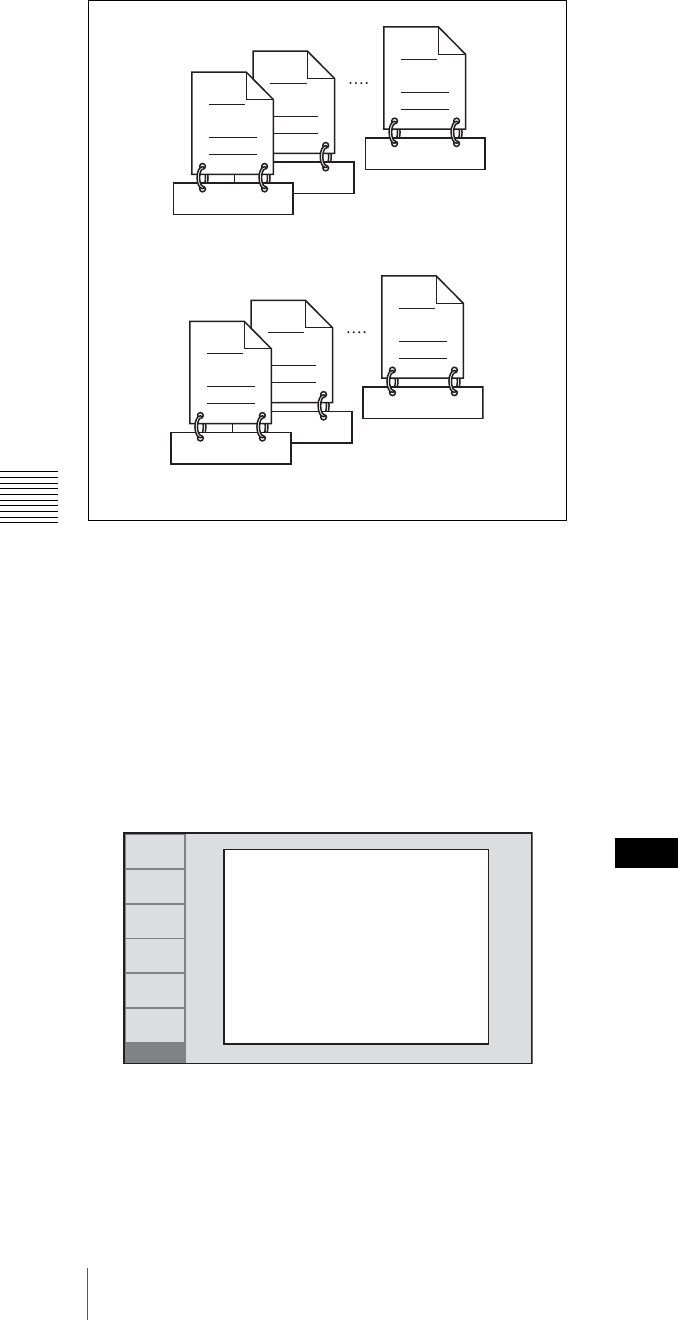
108 Overview
Chapter 6 File Operations
automatic title generation function allows you to assign
titles to all of the clips on several discs, which facilitates
clip management. For example, if the titles TITLE00001 to
TITLE00020 are assigned to clips C0001.MXF to
C0020.MXF on disc 1, then the titles TITLE00021 to
TITLE00037 are assigned to clips C0001.MXF to
C0017.MXF on disc 2.
Proceed as follows to specify a title and assign it to
recorded clips.
1
Press the MENU button.
2
Turn the PUSH SET(S.SEL) knob to select setup
menu item 035, and press the knob.
3
Turn the PUSH SET(S.SEL) knob to select “on”, and
press the knob.
The clip title naming screen appears.
4
Turn the PUSH SET(S.SEL) knob to move the asterisk
(*) on the left of the menu items to “TITLE”, and press
the knob.
The asterisk indicates the selected item.
5
Turn the PUSH SET(S.SEL) knob to select “enable”,
and press the knob.
The automatic title generation function is enabled.
6
Turn the PUSH SET(S.SEL) knob to move the asterisk
(*) on the left of the menu items to the item you want
to select, and press the knob.
PREFIX: A string of up to 10 characters. The
allowable characters are alphanumeric characters,
symbols (! # $ % & ' ( ) + ,- . ; = @ [ ] ^ _ { } ~),
and the space character.
NUMERIC: A five-digit number (00001 to 99999) to
serve as the initial value of the serial number.
7
Turn the PUSH SET(S.SEL) knob to select the
character position to set, and press the knob.
8
Turn the PUSH SET(S.SEL) knob to select the
character to set.
9
Repeat steps 7 and 8 as required.
When you are setting the “NUMERIC” item, you can
press the RESET/RETURN button to return the initial
value of the serial number to 00001 (factory default
setting).
10
Carry out steps 7 to 9 to set the other item.
11
Press the SAVE function (F5) button.
The title is saved.
To check the titles of recorded clips
Press the THUMBNAIL button to display the thumbnail
screen, and select the clip whose title you want to check.
The title of the selected clip appears at the upper left of the
screen.
See “Thumbnail Operations” (page 74) for more
information about the thumbnail screen.
• The value of the serial number is incremented by 1 every
time a title is generated. When the value reaches 99999,
the next number restarts from 00001.
• Duplicate clip titles can be generated if you reset the
serial number after recording several clips or the same is
true depending on the value setting. Care should be taken
when setting the serial number.
• The “PREFIX” setting is saved in memory banks, but the
“NUMERIC” setting is not saved (see page 125).
C0017.MXF
TITLE00037
C0002.MXF
TITLE00022
TITLE00021
C0001.MXF
Clips recorded on Disc 2
C0020.MXF
TITLE00020
C0002.MXF
TITLE00002
TITLE00001
C0001.MXF
Clips recorded on Disc 1
RETURN
SELECT
SAVE
SETUP
EXIT
ITEM-035
CLIP TITLE NAMING
SELECT
*TITLE - disable
PREFIX - TITLE
NUMERIC - 00001
Notes
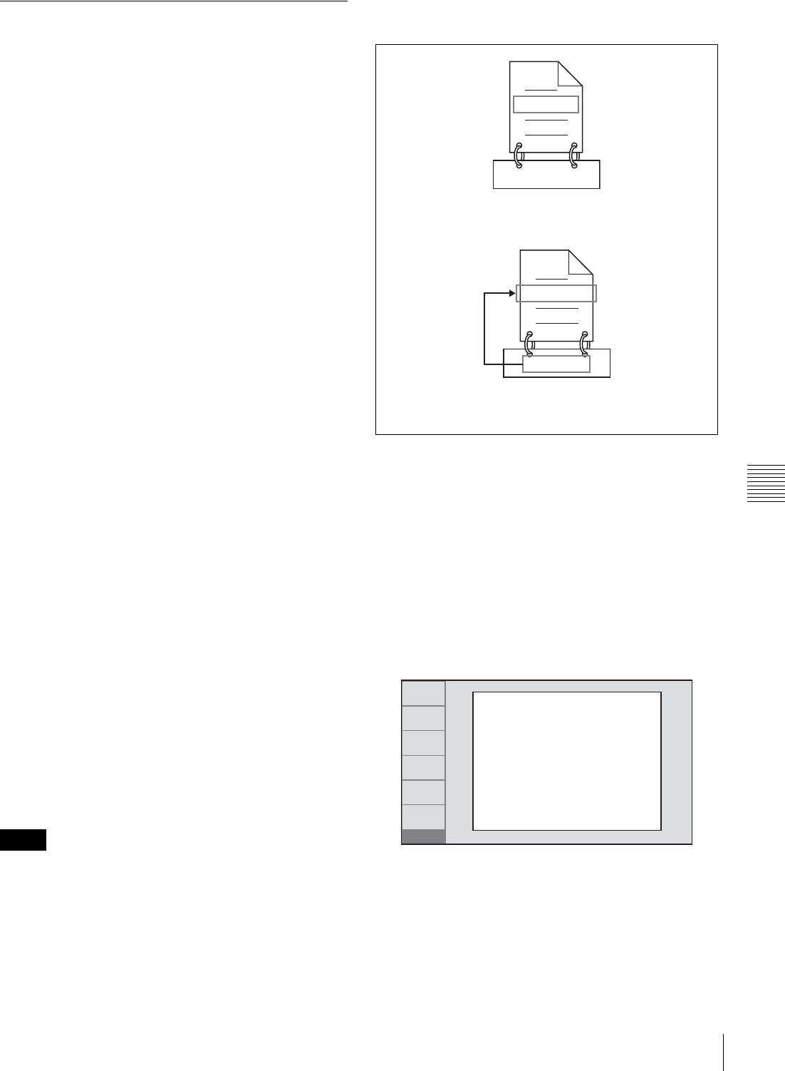
109
Overview
Chapter 6 File Operations
Assigning user-defined clip and clip
list names
The following standard format names are assigned
automatically to clips and clip lists that are created or
recorded by XDCAM devices.
Clips: C0001.MXF to C9999.MXF
Clip lists: E0001E01.SMI to E0099E01.SMI
This unit can handle clips and clip lists with user-defined
names as well as names in the standard format.
Limitations
• Letters, numbers and symbols from the Unicode 2.0
character set can be used.
However, the following control characters and symbols
cannot be used.
- Control characters: U+0000 to U+001F, U+007F
- Symbols: ", *, /, :, <, >, ?, \, |
• Depending on the character type, the length of user-
defined names (the “C*” or “E*E01” part) may be
limited to 14 characters. (The limit for ASCII characters
is 56 characters.)
• All file name extensions are converted automatically to
uppercase.
• Titles are used as user-defined clip names on this unit.
Therefore, the available characters are limited to those
supported by the title function.
• Files generated along with clips and clip lists use the
same names (the “C*” or “E*” part of the following file
names).
- Clips: Metadata files (C*M01.XML), user metadata
files (C*M02.KLV), proxy AV data files
(C*S01.MXF)
- Clip lists: Metadata files (E*M01.XML)
• The following names cannot be assigned.
- Clips: C0000.MXF
- Clip lists: E0000E01.SMI, E0100E01.SMI to
E9999E01.SMI, E0000.SMI, E0100.SMI to
E9999.SMI
• The following names should be avoided.
- Clips: C5000.MXF to C9999.MXF
- Clip lists: E0001.SMI to E0099.SMI
To assign clip names on this unit
The title assigned to clip becomes its clip name (file
name).
• When the first letter of the title setting with setup menu
item 035 CLIP TITLE NAMING SELECT is a space or
period (.), the clip name is the title string minus the first
letter.
• An FTP client that supports UTF-8 is required to use
Unicode characters other than ASCII characters.
Command prompt FTP commands do not support
UTF-8.
1
Before you start, set the “TITLE” sub item of setup
menu item 035 CLIP TITLE NAMING SELECT to
“enable”, and set a title (see the previous section).
2
Press the MENU button.
3
Turn the PUSH SET(S.SEL) knob to select setup
menu item 036.
4
Turn the PUSH SET(S.SEL) knob to move the “*” to
the left of the item names to “NAMING FORM”.
The “*” indicates the selected item.
5
Turn the PUSH SET(S.SEL) knob to select “free”, and
press the knob.
You are now able to use clips and clip lists with user-
defined names.
Notes
C0001.MXF
TITLE00001
When the “AUTO NAMING” sub item of setup menu
item 036 is set to “C****”
When the “AUTO NAMING” sub item of basic menu item
036 is set to “title”
TITLE00001.MXF
TITLE00001
RETURN
SELECT
SAVE
SETUP
EXIT
ITEM-036
FILE NAMING
* NAMING FORM - C****
AUTO NAMING - C****
END
110 File Operations in File Access Mode (for Windows)
Chapter 6 File Operations
6
Turn the PUSH SET(S.SEL) knob to move the “*” to
the left of “AUTO NAMING”, and press the knob.
7
Turn the PUSH SET(S.SEL) knob to select “title”, and
press the knob.
8
Press the SAVE function (F5) button.
The same name will now be given to newly recorded
clips.
To use clips and clip lists with user-defined
names over FAM and FTP connections
Carry out steps 2 to 5 of “To assign clip names on this
unit”, and then press the SAVE function (F5) button.
It is now possible to write, transfer, and rename clips and
clip lists with user-defined names over file access mode
(FAM) connections (page 110) and FTP connections
(page 114).
To check clip names
Press the THUMBNAIL button to display the thumbnail
screen, and select the clip whose name you want to check.
The name of the selected clip appears at the upper left of
the screen.
See “Thumbnail Operations” (page 74) for more
information about the thumbnail screen.
The item at the upper left of the screen is displayed
according to the following order of priority.
Title >User-defined clip name >Standard format clip name
Therefore, the display of this item changes as following,
depending on whether there is a title.
- When a title has been set as a clip name on this unit, for
clips recorded on this unit, the title is displayed.
- The user-defined name or standard format name is
displayed for clips without a title.
File Operations in File
Access Mode (for
Windows)
File access mode operating environment
Operating system requirements for file operations by file
access mode (called FAM below) are as follows.
• Computer operating system: Microsoft Windows XP
Professional SP2 or later, or Microsoft Windows Vista
Ultimate/Business (32-bit)
64-bit editions of Windows Vista are not supported.
Preparations
Install the FAM driver on the remote computer (see the
next section).
To install the FAM driver
Insert the supplied CD-ROM (XDCAM Application
Software) into the CD-ROM drive of your computer,
navigate to the FAM Driver directory, and run the installer
in the directory for your operating system, then follow the
installation instructions.
For details, refer to the ReadMe file contained on the CD-
ROM disc.
Use Version 2.10 or higher of the FAM driver. The FAM
driver on the supplied CD-ROM is Version 2.10 or higher.
If a FAM driver is already installed on your computer,
check the version.
To check the version
On Windows XP
Select “ProDisc” from “Add or Remove Programs” in the
control panel, and then click “Click here for support
information”.
On Windows Vista
(1) Open “Programs” >“Programs and Functions” in the
control panel, and then right click the header (where
“Name” and “Supplier” are displayed) and select
“Other...”.
(2) In the Advanced Settings dialog, check “Version” and
click “OK”. The version column appears. Check the
version of “ProDisc”.
Note
Sakura.SMI
Able to use clips with user-defined names
over FAM and FTP connections
Able to use clip lists with user-defined names
over FAM and FTP connections
Fuji.MXF
Note
Note
111
File Operations in File Access Mode (for Windows)
Chapter 6 File Operations
Making FAM connections
1
If there is a disc loaded in this unit, put the unit into the
following state.
• Recording, playback, search and other disc
operations (see page 54): Stopped
• THUMBNAIL button (see page 21): Off
• Disc access by Lock or Delecte All Clips, Format
Disc, and so on in the Disc Menu (see page 72):
Stopped
• Unsaved current clip list: Save or clear
2
If this unit is connected to a remote computer by FTP,
log out from the FTP session (see page 115).
3
Connect the (i.LINK) S400connector on this unit to
the i.LINK (IEEE1394) connector on the remote
computer, using an i.LINK cable (see connections
illustration on page 36).
Windows recognizes this unit as a removable disc, and
displays one of the following icons on the remote
computer’s task bar:
• Windows XP:
• Windows Vista:
The remote computer is now able to perform file
operations when a disc is inserted into this unit.
You will not be able to log in if you put the unit into
the state described in step 1 after connecting the cable.
To log in, disconnect the cable, put the unit into the
state described in step 1, and connect it again.
When you make your first FAM connection
The Found New Hardware Wizard dialog appears when
you connect this unit to your computer. Select “Install the
software automatically (Recommended)”, and then click
the Next button. Click the Finish button when the software
installation finishes.
Operation limitations during FAM connections
• Front panel operations are disabled, except for
operations with the EJECT button.
• This unit cannot be controlled from devices connected to
the REMOTE(9P) connector (D-sub 9-pin) and
(i.LINK) S400 connector.
• Signal input to this unit and signal output from this unit
are stopped.
Operating on files
1
Start Explorer.
Check that a drive letter has been assigned to this unit.
(The drive letter will differ depending on the number
of other peripherals connected to the remote
computer.)
2
Use Explorer to perform file operations on the disc
loaded in this unit.
You can operate in the same way that you operate on
local drives and files on network computers.
• If you power this unit off during an FAM
connection, the data transferred thus far is discarded.
• All file operations are not possible for some types of
files.
For details, see “File operation restrictions”
(page 105).
To eject discs from a remote computer
Right click the icon representing this unit in Explorer, and
select “Eject” from the menu which appears.
Exiting file operations
Do not disconnect the cable before performing steps 1 to 3.
1
Do one of the following on the or icon
displayed in the remote computer’s taskbar.
• Double click.
• Right click, and select the “Safely Remove
Hardware”.
The “Safely Remove Hardware” dialog appears.
2
Select “Sony XDCAM PDW-****** IEEE 1394
SBP2 Device” (******: “F1600” or “HD1500”) and
click “Stop”.
The “Stop a Hardware device” dialog appears.
3
Select “Sony XDCAM PDW-****** IEEE 1394
SBP2 Device” (******: “F1600” or “HD1500”) and
click “OK”.
•Windows XP: “Sony XDCAM PDW-****** IEEE
1394 SBP2 Device” (******: “F1600” or
“HD1500”) is deleted from the “Hardware devices”
list.
•Windows Vista: A message appears to inform you
that you can now safely remove the device from
your computer.
Note
Notes
Note

112 File Operations in File Access Mode (for Macintosh)
Chapter 6 File Operations
This unit can now resume normal operations. (The
limitations described in “Operation limitations during
FAM connections” no longer apply.)
4
Disconnect the i.LINK cable as required.
To reconnect
To reconnect after exiting file operations, do one of the
following, depending on whether an i.LINK cable is
connected.
i.LINK cable is not connected: Connect this unit and a
remote computer with an i.LINK cable.
i.LINK cable is connected: Disconnect the i.LINK cable
from either this unit or the remote computer, wait for
at least 10 seconds, and then reconnect the
disconnected cable.
The unit is powered off and an i.LINK cable is
connected: Power the unit on.
You can enable and disable FAM connection from the
function menu. For details, see page 52.
File Operations in File
Access Mode (for
Macintosh)
File access mode operating environment
Operating system requirements for file operations by file
access mode are as follows.
• Computer operating system: Mac OS X v10.4.11 or
higher
Preparations
Do the following on the remote computer and this unit.
• Install the FAM driver on the remote computer (see the
next item).
To install the FAM driver
Insert the supplied CD-ROM (XDCAM Application
Software) into the CD-ROM drive of your computer, and
execute the dmg file in FAM Driver >Mac >FAM Driver,
then follow the installation instructions.
For details, refer to the ReadMe file contained on the
CD-ROM disc.
To check the FAM driver version
Connect this unit to your computer with an i.LINK cable,
and then, with a disc loaded, start the system profiler utility
of the application. The version appears to the right of
“prodisk_fs” when you select “Advanced Functions”
under “Software”.
Making FAM connections
1
If there is a disc loaded in this unit, put the unit into the
following state.
• Recording, playback, search and other disc
operations (see page 54): Stopped
• THUMBNAIL button (see page 21): Off
• Disc access by clip deletion, disc formatting, etc.:
Stopped
• MENU button (see page 20): Off
• Unsaved current clip list: Save or clear
2
Connect the (i.LINK) S400 connector on this unit to
the i.LINK (IEEE1394) connector on the remote
computer, using an i.LINK cable (see page 36).
When a disc is inserted into this unit, the remote
computer recognizes this unit as a removable disc. The
following icon appears in the Finder on the remote

113
File Operations in File Access Mode (for Macintosh)
Chapter 6 File Operations
computer, indicating that the computer is now able to
perform file operations.
Operation limitations during FAM
connections
• With the exception of the EJECT button, recording
buttons and playback control buttons are disabled.
• Do not use the EJECT button to eject discs. Always eject
discs from the computer.
• Do not disconnect the i.LINK cable during a FAM
connection. Doing so may result in unstable operation.
Always eject any loaded disc before disconnecting the
i.LINK cable.
Operating on files
Proceed as follows.
1
Start the Finder.
Check to be sure that a drive has been assigned to this
unit.
2
Operate from the Finder on the files on the disc in this
unit.
You can operate in the same way that you operate on
local drives and files on network computers.
• If you power this unit off during a FAM connection, the
data transferred thus far is discarded.
• All file operations are not possible for some types of
files.
For details, see “File operation restrictions” (page 105).
To eject discs from a remote computer
Click the eject button to the right of the icon for this unit in
the Finder, or drag the icon for this unit from the Finder to
the Trash.
Exiting file operations
Proceed as follows.
Do not disconnect the cable before performing steps 1 and
2.
1
Eject the disc by clicking the eject button to the right
of the icon for this unit in the Finder, or by dragging
the icon for this unit from the Finder to the Trash.
2
Disconnect the i.LINK cable as required.
To make a reconnection
To reconnect after exiting file operations, do one of the
following, depending on whether an i.LINK cable is
connected.
i.LINK cable is not connected: Connect this unit and a
remote computer with an i.LINK cable.
i.LINK cable is connected: The unit is mounted
automatically, so you do not need to do anything.
The unit is powered off and an i.LINK cable is
connected: Power the unit on.
You can enable and disable FAM connection from the
function menu. For details, see page 52.
Notes
Note

114 FTP File Operations
Chapter 6 File Operations
FTP File Operations
File operations between this unit and a remote computer
can be carried out by the File Transfer Protocol (called
FTP below).
Preparations
1
Connect the network connectors of this unit and a
remote computer with a network cable (see
connections illustration on page 36). Or connect this
unit to the network to which the remote computer is
connected (see connections illustration on page 36).
2
Set the IP address and other network setting items for
this unit. 1)
For details, see “To change network settings”
(page 149).
If network settings have already been made
Check the IP address of this unit.
For details, see “To check the assigned IP address”
(page 149).
1) This unit is able to acquire an IP address automatically from a DHCP
server. It also supports an Auto-IP function to assign an IP address
automatically when access from this unit to the DHCP server times
out. You can check DHCP settings and the assigned IP address on
page M5:NETWORK of the maintenance menu.
If this unit is directly connected to a computer running
Windows Vista with a network cable, change the
setting as follows:
(1) Open “Network and Sharing Center” >“Manage
network connections” >“Local Area Connection” in
the control panel. (2) In the “Local Area Connection
Properties”, uncheck the “Internet Protocol Version 6
(TCP/IPv6)”, and then click the OK button.
3
Set the remote control switch to “NET” (see page 18).
Making FTP connections
FTP connections between this unit and a remote computer
can be made with either of the following.
• The command prompt
•FTP client software
This section explains how to use the command prompt. For
more information about using FTP client software, refer to
the documentation of the FTP client software on your
system.
An FTP client that supports UTF-8 is required to use
Unicode characters other than ASCII characters.
Command prompt FTP commands do not support UTF-8.
To log in
If this unit is connected to a remote computer with a FAM
connection, first exit file operations on the FAM
connection (see page 111).
1
Load a disc into this unit and put the unit into the
following state.
• Recording, playback, search and other disc
operations (see page 54): Stopped
• THUMBNAIL button (see page 21): Off
• Disc access by Lock or Delete All Clips, Format
Disc, and so on in the Disc Menu (see page 72):
Stopped
Login is not possible unless a disc is loaded and the
unit is in the state described above.
2
Start the command prompt.
3
Enter “ftp <SP> <IP address>”, and press the Enter
key. (<SP> refers to a space.)
For example, if the IP address of this unit is set to
“192.168.001.010”, enter “ftp 192.168.1.10”.
Refer to the Windows help for more information about
the FTP command.
If the connection succeeds, you are prompted to enter
a user name.
4
Enter the user name “admin” and press the Enter key.
When the user name is verified, you are prompted to
enter a password.
5
Enter the password and press the Enter key.
The password is set to the model name (“pdw-f1600”
or “pdw-hd1500”) when the unit is shipped from the
factory.
The login is complete when the password is verified.
See page 115 for the FTP protocol commands
supported by this unit.
If the connection times out
This unit terminates FTP connections if no command
is received within 90 seconds of the last command. If
this occurs, log out (see the next section) and repeat
steps 2 to 4.
Note
Note
Note

115
FTP File Operations
Chapter 6 File Operations
If you power this unit off during an FTP connection,
the data transferred thus far is discarded.
To log out
To log out after finishing file operations, enter “QUIT” at
the command prompt and press the Enter key.
Command list
The FTP protocol commands supported by this unit
include standard commands (see the next section) and
extended commands (see page 118).
• To execute FTP commands, you must install application
software such as PDZ-1 on your computer.
• The commands supported by application software vary.
• An FTP client that supports UTF-8 is required to use
Unicode characters other than ASCII characters.
Command prompt FTP commands do not support
UTF-8.
Standard commands
In the command syntax, <SP> means a space, entered by
pressing the space bar, and <CRLF> means a new line,
entered by pressing the Enter key.
USER
Send this command to begin the login process.
Command syntax: USER <SP> <user name> <CRLF>
Input example: USER admin
PASS
After sending the USER command, send this command to
complete the login process.
Command syntax: PASS <SP> <password> <CRLF>
Input example: PASS pdw-hd1500
QUIT
Terminates the FTP connection. If a file is being
transferred, terminates after completion of the transfer.
Command syntax: QUIT <CRLF>
PORT
Specifies the IP address and port to which this unit should
connect for the next file transfer (for data transfer from this
unit).
Command syntax: PORT <SP> <h1,h2,h3,h4,p1,p2>
<CRLF>
• h1 (most significant byte) to h4 (least significant byte): IP
address
• p1 (most significant byte), p2 (least significant byte): Port
address
Input example: PORT 10,0,0,1,242,48
(IP address: 10.0.0.1, Port number: 62000)
PASV
This command requests this unit to “listen” on a data port
(which is not its default data port). (It puts this unit into
passive mode, waiting for the remote computer to make a
data connection.)
Command syntax: PASV <CRLF>
TYPE
Specifies the type of data to be transferred.
Command syntax: TYPE <SP> <type-code (options
delimited by <SP>)> <CRLF>
<type-code> can be any of the following. However, for
XDCAM, data is always transferred as “I”, regardless of
the type-code specification.
• A: ASCII
- N: Non-print
- T: Telnet format
- C: ASA Carriage Control
• E: EBCDIC
- N: Non-print
- T: Telnet format
- C: ASA Carriage Control
• I: IMAGE (Binary) (default)
• L: LOCAL BYTE
- SIZE: byte size
Input example: TYPE I
STRU
Specifies the data structure.
Command syntax: STRU <SP> <structure-code>
<CRLF>
<structure-code> can be any of the following. However,
for XDCAM, the structure is always “F”, regardless of the
structure-code specification.
• F: File structure (default)
• R: Record structure
• P: Page structure
Input example: STRU F
Note
Notes

116 FTP File Operations
Chapter 6 File Operations
MODE
Specifies the transfer mode.
Command syntax: MODE <SP> <mode-code> <CRLF>
<mode-code> can be any of the following. However, for
XDCAM, the mode is always “S”, regardless of the mode-
code specification.
• S: Stream mode (default)
•B: Block mode
• C: Compressed mode
Input example: MODE S
LIST
Sends a list of files from this unit to the remote computer.
Command syntax: LIST <SP> <options> <SP> <path-
name> <CRLF>
<options> can be any of the following.
• -a: Also display file names that begin with “.”
• -F: Append “/” to directory names.
The following data is transferred, depending on whether
<path-name> specifies a directory or file.
• Directory specified: A list of the files in the specified
directory
• File specified: Information about the specified file
• No specification: A list of the files in the current directory
The wildcard characters “*” (any string) and “?” (any
character) may be used in <path-name>.
Input example 1: LIST-a Clip
Input example 2: LIST Clip/*.MXF
NLST
Sends a list of file names from this unit to the remote
computer, with no other information.
Command syntax: NLST <SP> <options or path-name>
<CRLF>
The following options may be specified when no path-
name is specified.
• -a: Also display file names that begin with “.”.
• -l: Display information other than file name (gives the same
result as the LIST command).
• -F: Append “/” to directory names.
The following data is transferred, depending on whether
<path-name> specifies a directory or file.
• Directory specified: A list of the file names only in the
specified directory
• No specification: A list of the file names only in the current
directory.
The wildcard characters “*” (any string) and “?” (any
character) may be used in <path-name>.
Input example 1: NLST-l
Input example 2: NLST Clip/*.MXF
RETR
Begins transfer of a copy of a file in the specified path on
this unit to the current directory on the remote computer.
Command syntax: RETR <SP> <path-name> <CRLF>
Input example: RETR Clip/C0001.MXF
STOR
Begins transfer of a copy of a file in the specified path on
the remote computer to the current directory on this unit.
Depending on the type of file transferred, the following
files are created.
•C*.MXF file 1)
-C*M01.XML file (metadata)
-C*M02.KLV file (user metadata)
-C*S01.MXF file (proxy AV data)
•E*E01.SMI file 2)
-E*M01.XML file (metadata)
1) *: 0001 to 9999
2) *: 0001 to 0099
• For C*.MXF files, the UMID of the copy source file is
not saved. However, it is saved if an immediately
preceding SITE UMMD extended command has been
issued.
• For C*.MXF files, some data, such as file header
metadata, may be missing.
• Depending on the transfer destination directory and the
file type, transfer may not be possible.
For details, see “File operation restrictions” (page 105).
Command syntax: STOR <SP> <path-name> <CRLF>
Input example: STOR Edit/E0001E01.SMI
RNFR
RNTO
Rename a file.
Specify the file to be renamed with the RNFR command,
and specify the new name with the RNTO command.
(Always follow a RNFR command with a RNTO
command.)
For details, see “File operation restrictions” (page 105).
Notes

117
FTP File Operations
Chapter 6 File Operations
Command syntax: RNFR <SP> <path-name (before
change)> <CRLF>
RNTO <SP> <path-name (after change)> <CRLF>
Input example: RNFR General/info.txt
RNTO General/clip_info.txt
DELE
Deletes the specified file on this unit.
Depending on the directory and file type, deletion may not
be possible.
For details, see “File operation restrictions” (page 105).
Command syntax: DELE <SP> <path-name> <CRLF>
Input example: DELE Clip/C0099.MXF
STAT
Sends information about properties of the specified file, or
about data transfer status, from this unit to the remote
computer.
The following property information is sent, depending on
the file type.
•MXF file
- File name
-File type
- CODEC type
- Frame rate
- Number of audio channels
- Duration
-UMID
• non-MXF file
- File name
Command syntax: STAT <SP> <path-name> <CRLF>
The following data is transferred, depending on whether a
file is specified with <path-name>.
• File specified: The properties of the specified file
• No specification: The size of the data transferred thus far
(unit: bytes)
Input example: STAT Clip/C0001.MXF
ABOR
Requests this unit to abort a file transfer currently in
progress.
Command syntax: ABOR <CRLF>
SYST
Displays the system name of this unit.
Command syntax: SYST <CRLF>
HELP
Displays a list of the commands supported by this unit, or
an explanation of the specified command.
Command syntax: HELP <SP> <command-name>
<CRLF>
The following data is transferred, depending on whether a
command name is specified with <command-name>.
• Command name specified: Explanation of the specified
command.
• No specification: Command list
Input example: HELP RETR
NOOP
Does nothing except return a response. (Used to check
whether this unit is running.)
Command syntax: NOOP <CRLF>
PWD
Displays the current directory (“/” if the directory is the
root directory).
Command syntax: PWD <CRLF>
CWD
Changes the current directory (moves from the current
directory to another directory).
Command syntax: CWD <SP> <path-name> <CRLF>
Moves to a directory as follows, depending on whether a
directory is specified with <path-name>.
• Directory specified: To the specified directory
• No specification: To the root directory
Input example: CWD General
CDUP
Moves one level up in the directory structure (makes the
parent of the current directory be the current directory).
Command syntax: CDUP <CRLF>
MKD
Creates a new directory.
Directories can be created only in the General directory.
For details, see “File operation restrictions” (page 105).
Command syntax: MKD <SP> <path-name> <CRLF>
Note
Note

118 FTP File Operations
Chapter 6 File Operations
RMD
Deletes a directory.
Directories can be deleted only in the General directory.
For details, see “File operation restrictions” (page 105).
Command syntax: RMD <SP> <path-name> <CRLF>
MDTM
Acquires the date and time of the most recent modification
of the file in the format “YYYYMMDDhhmmss” (YYYY:
year, MM: month, DD: day, hh: hour, mm: minute, ss:
second).
The date and time cannot be acquired in the following
cases.
• When the path name includes a wildcard (“*”, replaced
by any string of characters, or “?”, replaced by any single
character).
• When the size of the path name is greater than 1023
bytes.
Command syntax: MDTM <SP> <path-name> <CRLF>
Input example: MDTM PROAV/DISCMETA.XML
Extended commands
In the Command syntax, <SP> means a space, entered by
pressing the space bar, and <CRLF> means a new line,
entered by pressing the Enter key.
SITE REPF
Sends an MXF file from the specified path on this unit to
the remote computer. This command allows you to specify
a segment in the body of the MXF file (composed of video
and audio data), for transfer of the required segment only.
• A segment greater than the file size cannot be specified.
• This command cannot be used when the path names
contains a space. Use the SITE REPFL command
instead.
Command syntax: SITE REPF <SP> <path-name> <SP>
<start-frame> <SP> <transfer-size> <CRLF>
<start-frame> specifies an offset from the start of the file.
Data is transferred from the video frame at the offset (the
first frame is 0).
<transfer-size> specifies the number of video frames to
transfer (specify 0 to transfer to the end of the file).
Input example: SITE REPF Clip/C0001.MXF 5 150
(Transfer C0001.MXF. Body data is transferred only
from frame 6 to frame 150.)
SITE REPFL
Sends an MXF file from the specified path on this unit to
the remote computer. This command allows you to specify
a segment in the body of the MXF file (composed of video
and audio data), for transfer of the required segment only.
A segment greater than the file size cannot be specified.
Command syntax: SITE REPFL <SP> “<path-name>”
<SP> <start-frame> <SP> <transfer-size> <CRLF>
<path-name> specifies the path name of the file to transfer.
Enclose the path name in double quotation marks.
<start-frame> specifies an offset from the start of the file.
Data is transferred from the video frame at the offset (the
first frame is 0).
<transfer-size> specifies the number of video frames to
transfer (specify 0 to transfer to the end of the file).
Input example: SITE REPFL “Clip/sakura 0001.MXF” 5 150
(Transfer sakura 0001.MXF. Body data is transferred
only from frame 6 to frame 150.)
SITE FSTS
Acquires the system status of this unit.
One of the following status codes is sent.
• 0: Initial state, or no disc is loaded.
• 1: File system mount is OK.
• 3: File system mount is not OK.
Command syntax: SITE FSTS <CRLF>
SITE MEID
Acquires the media ID of the disc loaded in this unit.
Command syntax: SITE MEID <CRLF>
SITE FUNC
Acquires the function and version of the extended
commands.
Information is sent in the following format.
Command syntax: <main function> <SP> <branch
function> <SP> <branch function version>
For XDCAM, sent in a format like “200 MXF DISK 1”
(“200” is a response code).
Command syntax: SITE FUNC <CRLF>
Note
Note
Notes
Note

119
FTP File Operations
Chapter 6 File Operations
SITE UMMD
When a C*.MXF file is sent with the STOR command, the
copy source UMID is saved if this command is invoked
immediately before the STOR command.
Command syntax: SITE UMMD <CRLF>
SITE DF
Acquires the amount of free disc space.
Command syntax: SITE DF <CRLF>
SITE CHMOD
Locks and unlocks clips. Also sets permissions for
directories and files in the General directory.
Command syntax: SITE CHMOD <SP> <flag> <SP>
<path-name> <CRLF>
Specify one of the following values in <flag>, according to
the specification in <path-name>.
• When a clip is specified in <path-name>
- 444: Lock.
- 666: Unlock.
• When a directory in the General directory is specified in
<path-name>
- 555: Forbid writing to the directory.
- 777: Allow writing to the directory.
• When a file in the General directory is specified in <path-
name>
- 444: Forbid writing to and execution of the file.
- 555: Forbid writing to the file, but allow execution.
- 666: Allow writing to the file, but forbid execution.
- 777: Allow writing to and execution of the file.
Input example: SITE CHMOD 444 Clip/C0001.MXF
(Lock clip C0001.MXF)
SITE TCPR
Presets the starting timecode of a clip copied with the
STOR command. Specify the timecode in the format
“ffssmmhh” (ff: frames, ss: seconds, mm: minutes, hh:
hours).
• This command remains in effect until a STOR command
is executed, or (if no STOR command is executed) until
the FTP connection is terminated.
• If a SITE UMMD command is executed after this
command, the SITE UMMD command takes priority
and this command is discarded.
• If this command is executed several times in sequence,
the last command takes priority.
Command syntax: SITE TCPR <SP> <timecode >
<CRLF>
Input example: SITE TCPR 00050001
(The starting timecode is preset to 01:00:05:00.)
Notes

120 Recording Continuous Timecode with FAM and FTP Connections
Chapter 6 File Operations
Recording Continuous
Timecode with FAM and
FTP Connections
When you are connected to the unit by FAM or FTP, you
can create new clips with timecode that is continuous with
the timecode of the last frame of the last clip on the disc.
To record continuous timecode, set TCG on page P5 TC of
the function menu to “INT”, and set PRST/RGN to “TC”.
Then proceed as follows.
Continuous timecode cannot be recorded if PRST/RGN on
page P5 TC of the function menu is set to “VITC”.
See “Extended menu operations” (page 142) for more
information.
FAM connection
Write clip files to the unit from the computer or other
device that is connected to this unit.
FTP connection
Use the “STOR” command to transfer clip files from the
computer that is connected to this unit.
If you issue the “SITE UMMD” command immediately
before the “STOR” command, the original timecode of the
transferred file is recorded, regardless of the setting of
TCG on page P5 TC of the function menu.
Note

121
Menu System Configuration / Setup Menu
Chapter
Chapter 7 Menus
7
Menus
Menu System
Configuration
The settings for this unit use the following menus.
Setup menu
The setup menu system of this unit comprises the basic
setup menu and extended setup menu.
Maintenance menu
This provides audio control, and network and setup menu
settings, and also shows version information.
For details, see “Maintenance Menu” (page 144).
Function menu
For details, see “Basic Operations of the Function Menu”
(page 48).
Disc Menu
For details, see “Disc Operations” (page 92).
Setup Menu
The setup menu system of this unit comprises the basic
setup menu and extended setup menu.
Basic menu
This menu is used to make settings relating, for example,
to the following.
- the digital hours meter
- the preroll time
- the text information superimposed on the video output
to the monitor
- the menu banks for retaining menu settings
Extended menu
This menu is used to make a wide range of settings
relating to the functions of this unit, for example, the
control panel functions, video and audio control, and
digital data processing.
Configuration of the basic menu
The basic menu comprises the following groups of items.
Configuration of the extended menu
The extended menu comprises the following groups of
items.
Item group Function Refer to
Items
H01 to H17 Display of the total number of
hours the unit has been
powered on, and other
information collected by the
digital hours meter
page 155
Items
001 to 099 Settings relating to the preroll
time, superimposed text
information, switching between
59.94i/59.94P/29.97P and 50i/
50P/25P/23.98P modes, etc.
page 122
Items
B01 to B20 Settings relating to the menu
banks for saving menu settings page 125
122 Setup Menu
Chapter 7 Menus
Items in the basic menu
The basic menu items (excluding the items related to the
digital hours meter) are listed in the following table.
• Item names are the names which appear on the video
monitor screen of this unit and an external monitor,
when the input signals to the monitor are the video
signals output from the COMPOSITE OUTPUT 2
(SUPER) connector, the SDSDI OUTPUT 2 (SUPER)
connector, or the HDSDI OUTPUT 2 (SUPER)
connector.
• An abbreviated name appears in the time data display
area when you press the NEXT button.
• The values in the Settings column are the values which
appear in the time data display area. (The values may
appear in a different format on an external monitor. In
this case, the external monitor values are shown in
parentheses.) Underlined values are the factory defaults.
Item group Function Refer to
Items
100 to 199 Settings relating to control
panels page 129
Items
200 to 299 Settings relating to the remote
control interface page 130
Items
300 to 399 Settings relating to editing
operations page 131
Items
400 to 499 Settings relating to preroll page 132
Items
500 to 599 Settings relating to disc
protection page 132
Items
600 to 650 Settings relating to the
timecode generator page 133
Items
651 to 699 Settings relating to the
metadata and UMID page 134
Items
700 to 799 Settings relating to video
control page 136
Items
800 to 899 Settings relating to audio
control page 138
Items
900 to 999 Settings relating to digital
processing page 140
Item group Function Refer to
Item number Item name Settings
001 PREROLL TIME 0 s (0 sec)... 5 s (5 sec)... 30 s (30 sec): Set the preroll time to between 0
and 30 seconds in steps of 1 second.
A preroll time of at least 5 seconds is recommended when using this
unit for editing.
002 CHARACTER H-POSITION Adjust the horizontal screen position (as a hexadecimal value) of the text
information output from the COMPOSITE OUTPUT 2 (SUPER) connector,
the SDSDI OUTPUT 2 (SUPER) connector, or the HDSDI OUTPUT 2
(SUPER) connector for superimposed display on the monitor. The
hexadecimal value 00 is for the far left of the screen. Increasing the value
moves the position of the characters to the right.
00 ... 0C ... 28 (When the number of system lines is 1080 and the
system frequency is 59.94i, 29.97P, 50i, 25P, or 23.98P.)
00 ... 0B ... 28 (When the number of system lines is 720 and the system
frequency is 59.94P or 50P.)
Set this item by adjusting to the required position while viewing the monitor.
003 CHARACTER V-POSITION Adjust the vertical screen position (as a hexadecimal value) of the text
information output from the COMPOSITE OUTPUT 2 (SUPER) connector,
the SDSDI OUTPUT 2 (SUPER) connector, or the HDSDI OUTPUT 2
(SUPER) connector for superimposed display on the monitor. The
hexadecimal value 00 is for the top of the screen. Increasing the value
lowers the position of the characters.
00 ... 2A ... 32 (When the number of system lines is 1080 and the
system frequency is 59.94i, 29.97P, 50i, 25P, or 23.98P.)
00 ... 29 ... 32 (When the number of system lines is 720 and the system
frequency is 59.94P or 50P.)
Set this item by adjusting to the required position while viewing the monitor.

123
Setup Menu
Chapter 7 Menus
005 DISPLAY INFORMATION
SELECT Determine the kind of text information to be output from the COMPOSITE
OUTPUT 2 (SUPER) connector, the SDSDI OUTPUT 2 (SUPER) connector,
or the HDSDI OUTPUT 2 (SUPER) connector.
T&sta (time data & status): Time data and the units status.
T&UB (time data & UB): Time data and user bits data. (When UB (user bits
data) is selected with CNTR SEL on the HOME page of the function
menu, the user bits data and time data arranged in that order are
displayed.)
T&CNT (time data & CNT): Time data and counter count. (When
COUNTER is selected with CNTR SEL on the HOME page of the
function menu, the counter count and time data arranged in that order
are displayed.)
T&T (time data & timecode): Time data and timecode (TC or VITC)
T&clp (time data & clip no): Time data and clip number
time (time data only): Time data only
006 LOCAL FUNCTION ENABLE Determine which recording and playback control buttons on the front panel
are enabled when this unit is controlled from external equipment.
dis (all disable): All buttons and switches are disabled.
st&ej (stop & eject): Only the STOP button and EJECT button are enabled.
ena (all enable): All buttons and switches are enabled.
007 DISC TIMER DISPLAY Determine whether to display the counter in 12-hour mode or 24-hour mode.
+ –12H (+/–12H): 12-hour mode
24H: 24-hour mode
009 CHARACTER TYPE Determine the type of characters such as timecode output from the
COMPOSITE OUTPUT 2 (SUPER) connector, the SDSDI OUTPUT 2
(SUPER) connector, or the HDSDI OUTPUT 2 (SUPER) connector for
superimposed display on the monitor.
white: White letters on a black background
black: Black letters on a white background
W/out: White letters with black outline
B/out: Black letters with white outline
Set this item by selecting the required type while viewing the monitor.
011 CHARACTER V-SIZE Determine the vertical size of characters such as timecode output from the
COMPOSITE OUTPUT 2 (SUPER) connector, the SDSDI OUTPUT 2
(SUPER) connector, or the HDSDI OUTPUT 2 (SUPER) connector for
superimposed display on the monitor.
:Standard size
×2:2 times standard size
Set this item by selecting the required size while viewing the monitor.
012 CONDITION DISPLAY ON
VIDEO MONITOR Select whether to display disc condition marks in external monitor output
(output from the COMPOSITE OUTPUT 2 (SUPER) connector, the SDSDI
OUTPUT 2 (SUPER) connector, or the HDSDI OUTPUT 2 (SUPER)
connector).
dis (disable): Do not display.
ena (enable): Display.
Item number Item name Settings
×
1

124 Setup Menu
Chapter 7 Menus
013 SYSTEM FREQUENCY
SELECT MENU Specify whether to enable switching the system frequencies (59.94i, 59.94P,
29.97P, 50i, 50P, 25P, 23.98P).
off: Do not enable switching the system frequencies.
on: Enable switching the system frequencies.
For details about switching the system frequencies, see page 43.
Note
Settings for both basic and extended menu items are saved separately for
different system frequencies.
• 1080 59.94i/29.97P
• 1080 50i/25P
• 1080 23.98P
• 720 59.94P
• 720 50P
Therefore, when you switch system frequencies, all menu items are reset to
the current settings for the new mode. (They are different from the setting for
the previous mode.)
016 ALARM DISPLAY Select whether to display alarm messages.
off: Do not display alarm messages. (However, certain important alarms are
displayed.)
limit (on (limited)): Display only a minimum number of alarm messages.
on: Display all alarm messages.
For details about alarm message display conditions, see “Alarms”
(page 157).
017 SUB STATUS DISPLAY SELECT Determine the kind of sub status information to be output from the
COMPOSITE OUTPUT 2 (SUPER) connector, the SDSDI OUTPUT 2
(SUPER) connector, or the HDSDI OUTPUT 2 (SUPER) connector.
off: Do not output sub status information.
rmain (disc remain): Available disc space (unit: minute)
clip (clip no): Order of playback of the selected clip/total number of clips
pbr (playback remain): The remaining playback time of the selected clip
from the current playback position (hours:minutes:seconds:frames).
edit (edit preset): Edit preset state a)
ed&tc (edit preset & tc mode): Edit preset state and settings of timecode a)
Note
When menu item 005 is set to “off”, sub status information is not displayed
when this item is set to anything other than “off”.
024 MENU CHARACTER TYPE Determine the type of characters in menu text output from the COMPOSITE
OUTPUT 2 (SUPER) connector, the SDSDI OUTPUT 2 (SUPER) connector,
or the HDSDI OUTPUT 2 (SUPER) connector for superimposed display on
the monitor.
white: White letters on a black background.
black: Black letters on a white background.
W/out: White letters with black outline.
B/out: Black letters with white outline.
Set this item by selecting the required type while viewing the monitor.
028 HD CHARACTER Specify whether to superimpose text information on the video signal output
from the HDSDI OUTPUT 2 (SUPER) connector.
off: Do not superimpose.
f-key: Follow the function menu setting.
029 STORED OWNERSHIP Specify whether to enable changing UMID ownership information settings
(COUNTRY, ORGANIZATION and USER).
off: Do not enable.
on: Enable.
See “Using UMID Data” (page 171) for more information about UMID.
Item number Item name Settings
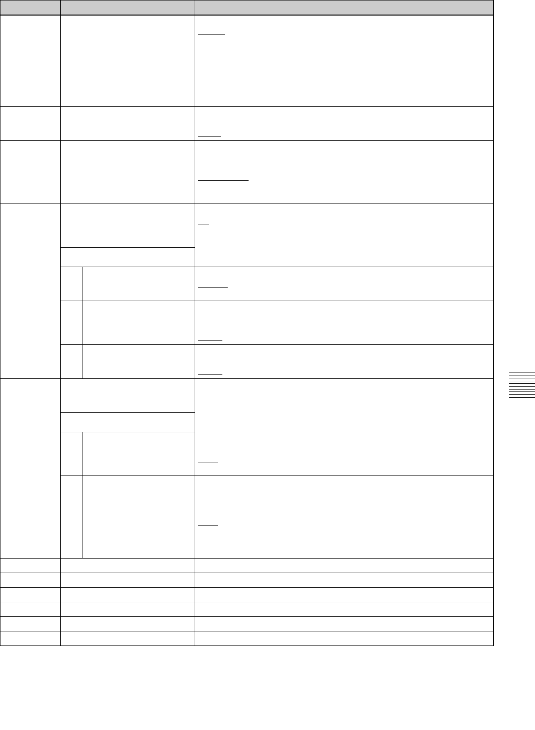
125
Setup Menu
Chapter 7 Menus
031 RECORDING FORMAT Set the recording format.
HD422: HD422
420HQ: HD420HQ
420SP: HD420SP
IMX50(IMX50Mbps): MPEG IMX 50 Mbps b)
IMX40(IMX40Mbps): MPEG IMX 40 Mbps b)
IMX30(IMX30Mbps): MPEG IMX 30 Mbps b)
DVCAM: DVCAM b)
033 BATTERY END VOLTAGE Sets the voltage to shut down the unit in the battery operation. The battery
near end indicator flashes at +0.7 V of the set voltage.
10.5V to 13.5V: 10.5 V to 13.5 V in 0.5 V unit.
034 MENU STATUS DISPLAY ON
VIDEO MONITOR a)
Specify whether to display the setup menu status at the left edge of the
status display line when setup menu item 005 “DISPLAY INFORMATION
SELECT” is set to “T&sta”.
dis (disable): Do not display.
ena (enable): Display. (The display is visible only when no disc is loaded,
and during insertion and ejection of a disc.)
035 CLIP TITLE NAMING SELECT Specify whether to allow user definition of the titles assigned to clips.
off: Do not allow assignment.
on: Allow assignment.
See “Assigning user-defined clip titles” (page 107) for more information
about assigning titles.
Sub-item
1 TITLE Specify whether to assign titles to recorded clips.
disable: Do not assign titles to clips.
enable: Assign titles to clips.
2 PREFIX Set the prefix of the title (up to 10 characters). The allowable characters are
alphanumeric characters, symbols (! # $ % & ' ( ) + , - . ; = @ [ ] ^ _ { } ~), and
the space character.
TITLE
3 NUMERIC Set the initial value of the numeric part of the title (00001 to 99999, five-digit
number).
00001
036 FILE NAMING Specify whether to allow use of clip and clip list files with user-defined
names.
See “Alarms relating to audio and video signals” (page 165) for details about
how to make the settings.
Sub-item
1 NAMING FORM Specify the clip and clip list naming format. (Specify whether to allow use of
files with user-defined names.)
C****: Standard format (Do not allow use of files with user-defined names)
free: Free format (Allow use of files with user-defined names)
2 AUTO NAMING When “free” is selected under the sub-item “NAMING FORM”, specify the
format of the names of clips recorded on this unit. Specify the standard
name format, or the same name as the title listed below, or the name
specified in planning metadata.
C****: Use the standard format for clip names.
title: Use the title set in setup menu item 035 “CLIP TITLE NAMING
SELECT” for clip names.
plan: Use the name specified in planning metadata.
B01 RECALL SETUP BANK-1 Set to “on” to recall menu settings from menu bank 1.
B02 RECALL SETUP BANK-2 Set to “on” to recall menu settings from menu bank 2.
B03 RECALL SETUP BANK-3 Set to “on” to recall menu settings from menu bank 3.
B11 SAVE SETUP BANK-1 Set to “on” to save current menu settings to menu bank 1.
B12 SAVE SETUP BANK-2 Set to “on” to save current menu settings to menu bank 2.
B13 SAVE SETUP BANK-3 Set to “on” to save current menu settings to menu bank 3.
Item number Item name Settings
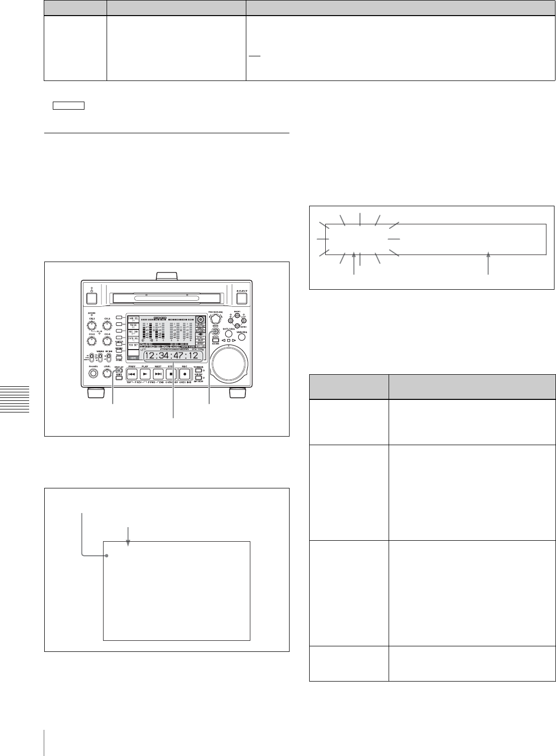
126 Setup Menu
Chapter 7 Menus
a) PDW-F1600 only
b) When the PDBK-S1500 or PDBK-F1500 option is installed.
Basic menu operations
The setup menus are displayed in the time data display area
of the basic operation display or on the video monitor
display. If you have connected an external monitor, they
are also superimposed over the picture shown on that
monitor.
To display the setup menu
Press the MENU button.
A setup menu appears on the video monitor display, and a
cursor “*” indicates the currently selected menu item.
To display menus on the external monitor
Connect the monitor to the COMPOSITE OUTPUT 2
(SUPER) connector, SDSDI OUTPUT 2 (SUPER)
connector, or HDSDI OUTPUT 2 (SUPER) connector on
this unit, and press the MENU button.
To display menus in the time data display area
Press the MENU button to display a setup menu on the
video monitor display, and press the DISPLAY button.
The video monitor display is switched the basic operation
display, and the number and setting of the currently
selected menu item appear in the time data display area.
To display the full item name
Hold down the NEXT button.
Buttons used to change settings
Use the following buttons to change setup menu settings.
B20 RESET SETUP MENU Set to “on” to return the settings of the current menu to the factory default
settings. Set to “bank-4” to set the current menu to the settings saved in
menu bank 4.
off:
on: Return the current menu to the factory default settings.
bank-4: Set the current menu to the settings saved in menu bank 4.
Item number Item name Settings
HD1500
MENU button
Time data display area
DISPLAY button
*HO1:OPE HOURS - 102
HOUR METER
H11:OPE HOURS r- 102
I
I
I
I
I
I
I
Group name for the currently selected item
Cursor indicating the currently selected item
Menu control
buttons Functions
MENU button • Displays and hides the setup and user
interface menus.
• Returns to the menu from a setting
screen.
PUSH
SET(S.SEL) knob • When turned clockwise or
counterclockwise, moves the “*” mark
up or down in the list of menu items to
select the item to change.
• When turned clockwise or
counterclockwise, changes a menu
item setting.
• When pressed, answers “Yes” to a
question.
Function buttons
F1 to F6
(The function to
be displayed
varies depending
on the situations.)
RETURN: Goes up one level.
SELECT: Selects an item.
UP: Skips back 100 or 50 items in the
list of menu items.
DOWN: Skips forward 100 or 50 items in
the list of menu items.
SAVE: Saves a new setting to memory.
EXIT: Exits the current menu.
–: Changes a setting.
+: Changes a setting.
RESET/RETURN
button • Returns the current setting to the
factory default.
• Answers “No” to a question.
H01: 000109
Item number (flashing) Setting

127
Setup Menu
Chapter 7 Menus
To change the settings of menu items
Proceed as follows to change the settings of menu items.
1
Use the PUSH SET(S.SEL) knob to select the required
item.
Example: Screen display when item 005 DISPLAY
INFORMATION SELECT is selected
2
Press the PUSH SET(S.SEL) knob or the SELECT
function button (F2).
This displays the setting screen 2 for the menu item
selected in step 1.
Example: Setting screen display when item 005
DISPLAY INFORMATION SELECT is selected
3
Use the PUSH SET(S.SEL) knob or the +/– function
button (F3 or F4) to change the setting.
Turning the PUSH SET(S.SEL) knob while holding
down the SHIFT button increases the increment of
adjustment.
4
To change other settings, press the PUSH SET(S.SEL)
knob or the SELECT function button (F2) to return to
the previous screen, then repeat steps 1 to 3.
5
When you have completed the settings, press the
SAVE function button (F5).
The message “NOW SAVING...” appears on the video
monitor display, and “Saving...” appears in the time
data display area, while the new settings are saved in
memory. When the saving operation is completed, the
video monitor display and the time data display area
return to their normal indications.
• If you power off the unit before a save operation is
completed, settings may be lost. Wait until the save is
completed before powering off the unit.
• If, instead of pressing the SAVE function button (F5),
you press the MENU button, the new settings are not
saved. The message “ABORT !” appears on the video
monitor display and “Abort !” in the time data display
area for about 0.5 seconds, and the system exits the
menus. To change more than one setting, be sure to press
the SAVE function button (F5) after making the settings.
To return menu settings to their factory
default settings
After changing menu settings, use the following procedure
to return the settings to their factory default settings
(setting initialization).
To return a particular setting to its factory default
setting
In the screen that selects the setting of that item, press the
RESET/RETURN button.
For example, proceed as follows to return the 005
DISPLAY INFORMATION SELECT item to its default
setting. This assumes that the setting has been changed
from the factory default “time data & status” in step 3 of
the procedure in “To change the settings of menu items”
(page 127).
1
Press the RESET/RETURN button.
“time data & status” (factory default setting) is
selected.
2
Press the SAVE function button (F5).
The setting returned to its factory default is saved in
memory as the current setting.
To return all settings to their factory default
settings
1
Press the MENU button to display the setup menu.
2
Press the RESET/RETURN button.
A message appears, to confirm whether you wish to
return all settings to their factory default settings.
0O1:P-ROLL TIME - 5 s
KEY PARAMETER
002:CHARA H-POS - 0A
003:CHARA V-POS - 2E
*005:DISPLAY SEL - T&CNT
006:LOCAL ENA - st&ej
007:DISC TIMER - +-12H
009:CHARA TYPE - white
011:CHARA SIZE - x1
012:COND DISPLY - dis
013:SYSTEM FREQ - off
016:ALARM - on
Current setting
ITEM-005
DISPLAY INFORMATION
SELECT
time data & CNT
Current setting
Notes
Message on the video
monitor display Initialize all items to factory
preset values?
Message in the time data
display area Init setup?

128 Setup Menu
Chapter 7 Menus
3
Press the SAVE function button (F5).
The message “NOW SAVING...” appears on the video
monitor display, and “Saving...” appears in the time data
display area, while the settings of all items are returned to
their factory default settings. These factory default settings
are saved in memory. If you power off the unit while
settings are being saved, settings may not be correctly
returned to their factory default settings. Wait until the
saving is completed before powering off the unit.
To abandon the resetting operation
Instead of pressing the SAVE function button (F5), press
the RESET/RETURN button. The display returns to the
top level of the setup menu, leaving the settings
unchanged.
To customize the display of setup menu
items
You can select the menu items displayed in the setup
menu.
1
Set maintenance menu item M41: CUSTOMIZE to
“ENABLE”.
See page 148 for information about how to use the
maintenance menu.
2
Hold down the MENU button for about three seconds.
The SETUP CUSTOMIZE screen appears.
3
Turn the PUSH SET(S.SEL) knob so that the “*” mark
appears next to the item you want to hide or display in
the setup menu.
You can press the UP function button (F3) or the
DOWN function button (F4) to move the “*” mark by
100 menu items.
4
Press the PUSH SET(S.SEL) knob.
A setting screen for the currently selected item
appears.
5
Turn the PUSH SET(S.SEL) knob to select “on” or
“off”.
on: Display the item in the setup menu.
off: Do not display the item in the setup menu.
6
Press the PUSH SET(S.SEL) knob.
To continue selecting items
Repeat steps 3 to 6.
To set items more quickly
In step 3, turn the PUSH SET(S.SEL) knob to move
the “*” mark, and then press the ON function button
(F1) or OFF function button (F2) to set items
continuously.
7
Press the SAVE function button (F5).
Customization indication in the setup menu
When you open the setup menu after customizing the
displayed menu item, a “[C]” mark appears at the upper
right of the screen to indicate that the menu has been
customized.
ON
OFF
UP
DOWN
SAVE
SETUP
EXIT
SETUP CUSTOMIZE
*H01:OPE HOURS - on
H02:LASER0 - on
H03:LASER1 - on
H11:OPE HOURS r- on
H13:SEEK HOURS0r- off
H14:SPDL HOURS r- off
H15:LOAD COUNT r- off
H17:SEEK HOURS1r- off
001:P-ROLL TIME - off
002:CHARA H-POS - off
003:CHARA V-POS - off
ON
OFF
UP
DOWN
SAVE
SETUP
EXIT
SETUP CUSTOMIZE
H01:OPE HOURS - on
H02:LASER0 - on
H03:LASER1 - on
H11:OPE HOURS r- on
*H13:SEEK HOURS0r- off
H14:SPDL HOURS r- off
H15:LOAD COUNT r- off
H17:SEEK HOURS1r- off
001:P-ROLL TIME - off
002:CHARA H-POS - off
003:CHARA V-POS - off
RETURN
-
+
SAVE
SETUP
EXIT
CUSTOM ITEM-H13
SEEK RUNNING HOURS 0
(resettable)
on

129
Setup Menu
Chapter 7 Menus
Items in the extended menu
The following tables show the items in the extended menu.
• Item names are the names which appear on an external
monitor to which the output of the COMPOSITE
OUTPUT 2 (SUPER) connector, the SDSDI OUTPUT 2
(SUPER) connector, or the HDSDI OUTPUT 2
(SUPER) connector is input.
• An abbreviated name appears in the time data display
area when you press the NEXT button.
• The values in the Settings columns are the values which
appear in the time data display area. (The values may
appear in a different format on an external monitor. In
this case, the external monitor values are shown in
parentheses.) Underlined values are the factory defaults.
Menu items in the 100s, relating to the control panels
Item number Item name Settings
101 SELECTION FOR SEARCH DIAL
ENABLE Select how the unit enters the shuttle, jog, or variable speed mode.
dial (dial direct): Press the SHTL/JOG or VAR/JOG button or, except
during recording/editing, turn the jog dial or shuttle dial.
key (via search key): Press the SHTL/JOG or VAR/JOG button.
105 REFERENCE SYSTEM ALARM Select whether to display a warning when the reference video signal is
not being supplied, or when it differs from this unit’s system frequency.
off: No warning.
on: Flash the STOP button as a warning.
107 REC INHIBIT LAMP FLASHING Select whether to flash the REC INHI indicator when recording is
prevented (see “REC INHI (recording inhibit) indicator” (page 22).
off: Light the REC INHI indicator.
on: Flash the REC INHI indicator.
108 AUTO EE SELECT When a disc is inserted and PB/EE on the HOME page of the function
menu is set to “EE”, select the operation modes in which input video and
audio signals are automatically handled in E-E mode.
S/F/R (stop/f.fwd/f.rev): In stop/fast-forward/fast-reverse modes
stop: In stop mode
109 FORCED EE WHEN DISC UNLOAD During disc loading/unloading and when no disc is inserted, select
whether to control the output signal PB/EE setting.
on: Do not control (the signal is always an E-E signal).
off: Control.
114 AUDIO MONITOR OUTPUT LEVEL Select whether to control the level of the audio signal output from the
AUDIO MONITOR R, L connectors with the LEVEL knob for the
PHONES jack.
var (variable): Control.
fixed: Do not control.
118 KEY INHIBIT SWITCH EFFECTIVE
AREA Select which buttons can be operated when the KEY INHI switch is set to
“ON”. The following sub-items control different sets of buttons
independently.
Sub-item
1 FUNCTION-KEY Select whether function buttons on the front panel are enabled.
dis (disable): Disabled.
ena (enable): Enabled.
2 CONTROL PANEL Select operable buttons on the front panel are enabled.
dis (disable): Disabled.
ena (enable): Enabled.
119 VARIABLE SPEED LIMIT IN KEY Select the playback speed range when carrying out playback in variable
speed mode from the front panel of this unit.
off (off (–2 to +2)): –2 to +2 times normal speed.
on (on ( 0 to +1)): 0 to +1 times normal speed.
121 FRAME PB MODE Select the variable playback field/frame mode.
auto: Field playback
frame: Frame playback. Compared to field playback, frame playback
gives more detail during playback of still pictures.
130 DISPLAY DIMMER CONTROL Set the brightness of the indication on the LCD.
10%, 25%, 50%, 75%, 100%
130 Setup Menu
Chapter 7 Menus
a) The disc is ejected after recording stops. b) The unit enters stop mode when the PLAY button is pressed. It enters
freeze picture mode (jog, shuttle, or variable mode) when the SHTL/JOG
button or VAR/JOG button is pressed.
131 AUDIO VOLUME Select whether each of the CH-1/ALL CH, CH-2 to CH-4 adjustment
knobs on the control panel is effective to control the audio recording level
and playback level on each channel or the CH-1/ALL CH adjustment
knob alone functions as a master control to control the audio level on all
channels together.
each: Each of the CH-1/ALL CH, CH-2 to CH-4 adjustment knobs is
effective to control each channel.
all: The CH-1/ALL CH adjustment knob alone functions as a master
control.
When “all” is selected, the ALL CH indicator under the CH-1/ALL CH
adjustment knob lights up.
140 AREA MARKER Select whether to display the display area of SD output on the color LCD.
off: Do not display.
on: Display.
142 REPEAT MODE Put the unit into repeat playback mode, or exit from repeat playback
mode.
off: Exits from repeat playback mode.
play: Puts the unit into repeat playback mode.
143 INDEX PICTURE POSITION Select the frame of the clip to use as the thumbnail image (index picture)
when recording.
0sec to 10sec: Can be set in the range from 0 seconds (first frame of the
clip) to10 seconds, in units of 1 second.
145 MODE KEY ENABLE DURING
RECORDING Select whether the STOP button is the only button that stops recording.
ena (all enable): Recording stops when the EJECT button a), PLAY
button, STOP button, SHTL/JOG button, and VAR/JOG button b) are
pressed.
stop: Recording stops only when the STOP button is pressed.
150 REC MODE Select the recording mode.
normal: Normal recording mode
D.EXC (disc exchange cache): Disc Exchange Cache mode
C.REC (clip continuous rec): Clip Continuous Rec mode
151 GUI OPERATION Select whether to disable the display of the Thumbnail Menu and Disc
Menu when this unit is in any mode other than stop mode.
ena(enable): Do not disable.
stop(via stop): Enable the display of menus in the stop mode.
dis(disable): Disable.
153 FIND MODE Specify the frame to be cued up when the PREV or NEXT button is
pressed.
clip: The first frame of the clip
R.ST (clip & rec start mark): The frame where a Rec Start essence
mark is set (if no essence mark is set, the first frame of the clip)
154 SINGLE CLIP PLAY MODE Put the unit into single clip playback mode, or exit from single clip
playback mode.
off: Exits from single clip playback mode. (Puts the unit into continuous
playback mode.)
on: Puts the unit into single clip playback mode.
Menu items in the 100s, relating to the control panels
Item number Item name Settings
Menu items in the 200s, relating to the remote control interface
Item number Item name Settings
201 PARA RUN Select whether to use synchronized operation for two or more VTRs.
dis (disable): No synchronized operationena
ena (enable): Use synchronized operation
Note
To use synchronized operation for two or more VTRs, set item 201 to ena
on all of the VTRs.
131
Setup Menu
Chapter 7 Menus
a) When the PDBK-S1500 or PDBK-F1500 option is installed.
b) When the PDBK-201 option board is installed
c) FTP connections can be made only when the device connected to the
REMOTE(9P) connector (D-sub 9 pin) is in stop mode. During FTP
connections, the device connected to the REMOTE(9P) connector cannot
be used to control this unit.
212 VIDEO REMOTE CONTROL
SELECT a)
Select whether to control the up converter or down converter when
controlling the image enhancer from the HKDV-900 or another unit
connected to the VIDEO CONTROL connector.
down: Control the down-converter.
up: Control the up-converter.
u&d: Control both the up- and down-converter.
Note
It is also possible to adjust setup menu item 718 SETUP LEVEL/BLACK
LEVEL from the HKDV-900. Hold down the D2 button on the HKDV-900
and rotate the SETUP dial.
214 REMOTE INTERFACE When the remote control switch is set to REMOTE, select the device from
which to remote-control this unit.
9PIN: Device connected to the REMOTE(9P) connector.
SDI: Device connected to the SD/HDSDI INPUT connector.
i.LINK: Device connected to the (i.LINK) S400 connector. b)
215 i.LINK MODE b) Select the connection method for the (i.LINK) S400 connector.
FAM (FAM (PC REMOTE)): FAM connection
TS: TS connection
257 NETWORK ENABLE Select the remote control switch positions which enable network
connections.
net (network): Only when the switch is set to “NET”.
n&9P (network & remote(9PIN)): When the switch is set to “NET”, and
when the switch is set to “REMOTE” and setup menu item 214 is set
to “9PIN”. c)
Menu items in the 200s, relating to the remote control interface
Item number Item name Settings
HD1500
Menu items in the 300s, relating to editing operations
Item number Item name Settings
301 VAR SPEED RANGE FOR
SYNCHRONIZATION Select the playback speed range when carrying out playback in variable
speed mode from a remote control unit connected to the REMOTE(9P)
connector.
–2~+2: –2 to +2 times normal speed.
wide: –2.20 to +2.20 times normal speed.
311 [F1600]
ANALOG AUDIO EDIT PRESET
REPLACE FOR CH1
Select methods for setting the edit presets of the digital audio channels
CH1 to CH4 of this unit. Make these settings when using an editor (PVE-
500, BVE-600, etc.) or remote control unit without a function to control
digital audio edit presets.
The edit presets of the digital audio channels of this unit are turned on
and off according to the specified analog audio presets of the editor or
remote control unit.
nodef (no definition): No definition
ch 1 (analog ch1): Follow the edit preset of analog channel 1.
ch 2 (analog ch2): Follow the edit preset of analog channel 2.
ch1+2 (analog ch1+ch2): Follow the edit preset of analog channel 1 or
2.
(The default settings for each item are as follows)
311: ch 1 (analog ch1)
312: ch 2 (analog ch2)
313: nodef (no definition)
314: nodef (no definition)
312 [F1600]
ANALOG AUDIO EDIT PRESET
REPLACE FOR CH2
313 [F1600]
ANALOG AUDIO EDIT PRESET
REPLACE FOR CH3
314 [F1600]
ANALOG AUDIO EDIT PRESET
REPLACE FOR CH4
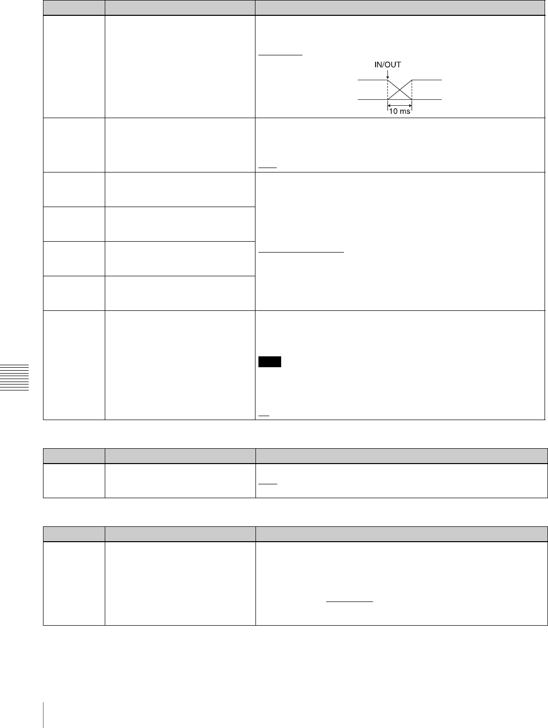
132 Setup Menu
Chapter 7 Menus
317 [F1600]
AUDIO EDIT MODE Select the type of audio transition used for linear editing.
cut edit: Cut editing (audio discontinuity at transition point, and possible
noise during playback).
cross fade: Cross-fade
320 DIGITAL AUDIO PB PROCESS ON
EDIT POINT Specify the handling of audio at edit points and at the second and
subsequent recording start points in Clip Continuous Rec recording.
cut: Carry out a cut (possibly resulting in audio discontinuities at the edit
point).
fade: Fade out and fade in.
329 [F1600]
ANALOG AUDIO EDIT PRESET
REPLACE FOR CH5
Select methods for setting the edit presets of the digital audio channels
CH5 to CH8 of this unit. Make these settings when using an editor
(PVE-500, BVE-600, etc.) or remote control unit without a function to
control digital audio edit presets.
The edit presets of the digital audio channels of this unit are turned on
and off according to the specified analog audio presets of the editor or
remote control unit.
nodef (no definition): No definition
ch 1 (analog ch1): Follow the edit preset of analog channel 1.
ch 2 (analog ch2): Follow the edit preset of analog channel 2.
ch1+2 (analog ch1+ch2): Follow the edit preset of analog channel 1 or
2.
330 [F1600]
ANALOG AUDIO EDIT PRESET
REPLACE FOR CH6
331 [F1600]
ANALOG AUDIO EDIT PRESET
REPLACE FOR CH7
332 [F1600]
ANALOG AUDIO EDIT PRESET
REPLACE FOR CH8
344 ASSEMBLE AUTO EDIT
POSTROLL RECORDING Set whether to record 2 seconds of postroll when an additional clip is
recorded by sending the AUTO EDIT command (9-pin protocol 20·42)
from a nonlinear editing system connected to the REMOTE(9P)
connector on the rear panel.
Note
When using a linear editing system, postroll will not be recorded
regardless of this setting.
off: Do not record postroll.
on: Records approximately 2 seconds of postroll.
Menu items in the 300s, relating to editing operations
Item number Item name Settings
Menu items in the 400s, relating to preroll
Item number Item name Settings
401 FUNCTION MODE AFTER CUE-UP Select the state that the unit goes into after a cuing-up operation.
stop: Stops (the stop mode).
still: Still playback (in jog and shuttle mode).
Menu items in the 500s, relating to disc protection
Item number Item name Settings
501 STILL TIMER To protect the disc against shock and vibrations, and to lengthen the life
of the laser diodes, the unit automatically enters standby off mode
whenever a specified time elapses in a disc stop mode (stop mode or the
still picture mode of search mode). This allows you to set the time after
which the unit exits a disc stop mode and enters standby off mode.
0.5 s (0.5 sec)... 8 m (8 min)... 30 m (30 min): Can be set in the range
from 0.5 seconds to 30 minutes.
off: Do not put into standby off mode.
133
Setup Menu
Chapter 7 Menus
Menu items in the 600s, relating to the timecode, metadata, and UMID
Item number Item name Settings
601 VITC POSITION
SEL-1 b)
In 59.94i/59.94P/
29.97P mode Select the line into which to insert VITC signals (SD output)
12H ... 16H ... 20H: Any line from line 12 through line 20.
Notes
• You can insert VITC signals in two places. To insert in two places, set
both item 601 and item 602.
• In 59.94i/59.94P/29.97P/23.98P mode (J), output of wide picture
information is given priority if OUTPUT in setup menu item 731 is set to
“auto” and the VITC insertion line is set to line 16.
• In 59.94i/59.94P/29.97P/23.98P mode (UC), output of wide picture
information is given priority if OUTPUT in setup menu item 731 is set to
“auto” and the VITC insertion line is set to line 20.
In 50i/50P/25P
mode Select the line into which to insert VITC signals (SD output)
9H ... 19H ... 22H: Any line from line 9 through line 22.
Note
You can insert VITC signals in two places. To insert in two places, set
both item 601 and item 602.
602 VITC POSITION
SEL-2 b)
In 59.94i/59.94P/
29.97P mode Select the line into which to insert VITC signals (SD output)
12H ... 18H ... 20H: Any line from line 12 through line 20.
Notes
• You can insert VITC signals in two places. To insert in two places, set
both item 601 and item 602.
• In 59.94i/59.94P/29.97P mode (J), output of wide picture information is
given priority if OUTPUT in setup menu item 731 is set to “auto” and the
VITC insertion line is set to line 16.
• In 59.94i/59.94P/29.97P mode (UC), output of wide picture information
is given priority if OUTPUT in setup menu item 731 is set to “auto” and
the VITC insertion line is set to line 20.
In 50i/50P/25P
mode Select the line into which to insert VITC signals (SD output)
9H ... 21H ... 22H: Any line from line 9 through line 22.
Note
You can insert VITC signals in two places. To insert in two places, set
both item 601 and item 602.
605 TCG REGEN MODE Select the signal to be regenerated when the timecode generator is in the
regeneration mode.
TC&UB: Both the timecode and user bits are regenerated.
TC: Only the timecode is regenerated.
UB: Only the user bits are regenerated.
607 U-BIT BINARY GROUP FLAG Select the user bits to be used in the timecode generated by the
timecode generator.
000 (000:not specified): Character set not specified.
001 (001:iso character): 8-bit characters compliant with ISO 646 and
ISO 2022.
010 (010:unassigned-1): Undefined.
011 (011:unassigned-2): Undefined.
100 (100:unassigned-3): Undefined.
101 (101:page / line): SMPTE-262M page/line multiplex system.
110 (110:unassigned-4): Undefined.
111 (111:unassigned-5): Undefined.
134 Setup Menu
Chapter 7 Menus
610 [F1600]
REGEN CONTROL MODE Select whether or not the time code is automatically regenerated.
auto(assem & insert)edit: In automatic editing carried out in either
assemble mode or insert mode with this unit as the recorder,
regardless of the settings of F1 (TCG) and F2 (PRST/RGN) in
function menu page 5, the time code generator regenerates
according to the time code on the disc.
auto assemble edit: In automatic editing carried out in assemble mode
with this unit as the recorder, regardless of the settings of F1 (TCG)
and F2 (PRST/RGN) in function menu page 5, the time code
generator regenerates according to the time code on the disc.
manual: Regardless of whether this unit is the recorder or player, the
time code generator operates in accordance with the settings of F1
(TCG) and F2 (PRST/RGN) in function menu page 5.
assemble & insert: Whether local or remote and regardless of the
settings of F1 (TCG) and F2 (PRST/RGN) in function menu page 5,
the time code generator regenerates according to the time code
played back from the disc.
611 TC OUTPUT PHASE IN EE MODE Select the timecode output mode for output from the TIME CODE OUT
connector in E-E mode.
thru (through): Output the timecode input to the TIME CODE IN
connector as it is.
v-in (video input phase): Output the timecode with the same phase as
the input video signal phase.
v-out (video output phase): Output the timecode with the same phase
as the output video signal phase.
612 TC OUTPUT MUTING IN SEARCH
MODE Select whether to suppress the output from the TIME CODE OUT
connector in jog/shuttle mode.
on: Suppress.
off: Do not suppress.
618 UPCONV EMBEDDED VITC a) Select the source of the VITC embedded into output HDSDI when up
converting during playback of SD discs.
VITC: Select the VITC of the SD disc.
LTC: Select the LTC of the SD disc.
619 VITC a) Select whether to record the VITC generated by the internal timecode
generator during IMX recording.
off: Do not record the internally generated VITC.
on: Record the internally generated VITC.
Note
Even if this item is set to “off”, VITC is recorded if the input video signal
contains VITC and the VITC line is set to “thru” in menu item 723.
651 UMID SDI OUTPUT Select whether to output UMID in the VANC of the SDI output.
off: Do not output.
on: Output.
See “Using UMID Data” (page 171) for more information about UMID.
652 UMID SD VANC LINE b) Select the line in which UMID is output when menu item 651 is set to
“on”.
12 H (12 line), 13 H (13 line), 15 H (15 line), 16 H (16 line), 17 H (17
line), 18 H (18 line), 19 H (19 line) (59.94i/59.94P/29.97P mode)
9 H (9 line), 10 H (10 line), 12 H (12 line), 13 H (13 line), 14 H (14 line),
15 H (15 line), 16 H (16 line), 17 H (17 line), 18 H (18 line) (50i/50P/
25P mode)
See “Using UMID Data” (page 171) for more information about UMID.
Menu items in the 600s, relating to the timecode, metadata, and UMID
Item number Item name Settings
135
Setup Menu
Chapter 7 Menus
a) When the PDBK-S1500 or PDBK-F1500 option is installed.
b) Not displayed when the unit is in 23.98P mode.
653 UMID HD VANC LINE Specify the HDSDI signal VANC line into which the UMID should be
inserted.
9H to 17H to 20H (59.94i, 50i, 29.97P, 25P, 23.98P mode)
9H to 17H to 25H (59.94P, 50P mode)
Note
The output VANC line during playback follows the setting for recording.
See “Using UMID Data” (page 171) for more information about UMID.
657 ESSENCE MARK SDI OUTPUT Select whether to output essence marks in the SDI output VANC.
off: Do not output.
on: Output.
660 ESSENCE MARK SD VANC LINE b) When menu item 657 is set to “on”, select the line to which to output
essence marks.
12 H (12 line), 13 H (13 line), 15 H (15 line), 16 H (16 line), 17 H (17
line), 18 H (18 line), 19 H (19 line) (59.94i/59.94P/29.97P mode)
9 H (9 line), 10 H (10 line), 12 H (12 line), 13 H (13 line), 14 H (14 line),
15 H (15 line), 16 H (16 line), 17 H (17 line), 18 H (18 line) (50i/50P/
25P mode)
665 ESSENCE MARK HD VANC LINE When item 657 is set to “on”, select the line to which to output essence
marks.
9H to 17H to 20H (59.94i, 50i, 29.97P, 25P, 23.98P mode)
9H to 17H to 25H (59.94P, 50P mode)
Note
The output VANC line during playback follows the setting for recording.
666 METADATA ITEM OUT Specify whether to include the information from recorded VANC packets
in data items in the DATA ITEM section of MXF files.
off: Do not include VANC packet information in data items.
on: Include VANC packet information in data items.
668 USER META DATA OUTPUT IN
MXF Select whether to output user metadata to MXF files.
off: Do not output.
on: Output.
Menu items in the 600s, relating to the timecode, metadata, and UMID
Item number Item name Settings
HD1500
136 Setup Menu
Chapter 7 Menus
Menu items in the 700s, relating to video control
Item number Item name Settings
703 BLANK LINE SELECT Switch blanking of the video output signal on or off for individual lines in
the vertical blanking interval.
Sub-Item The Y/C signal and odd/even fields are blanked simultaneously.
ALL LINE - - -: Specify the blanking for each line separately.
blnk (blank): Regardless of the setting of other sub-items, blank all lines
which can be specified in this menu item.
thru (throu): Regardless of the setting of other sub-items, switch off
blanking for all lines which can be specified in this menu item.
In 59.94i/
59.94P/29.97P
mode (UC)
LINE 12 ...
LINE 19 Specify blanking for lines 12 to 19.
blnk (blank): Carry out blanking.
thru (throu): Switch off blanking.
LINE 20 Specify blanking for line 20.
blnk (blank): Carry out blanking.
half: Carry out half-blanking.
thru (throu): Switch off blanking.
In 59.94i/
59.94P/29.97P
mode (J)
LINE 12 …
LINE 20 Specify blanking for lines 12 to 20.
blnk (blank): Carry out blanking.
thru (throu): Switch off blanking.
LINE 21 Specify blanking for line 21.
blnk (blank): Carry out blanking.
half: Carry out half-blanking.
thru (throu): Switch off blanking.
In 50i/50P/25P
mode LINE 9 ...
LINE 22 Specify blanking for lines 9 to 22.
blnk (blank): Carry out blanking.
thru (throu): Switch off blanking.
LINE 23 Specify blanking for line 23.
half: Carry out half-blanking.
thru (throu): Switch off blanking.
705 EDGE SUBCARRIER REDUCER
MODE Select whether to enable the edge subcarrier reducer (ESR).
on: Enable.
off: Do not enable.
When playing back a composite signal, set this to “on”.
707 FORCED VERTICAL
INTERPOLATION OFF The “Y-add” function is normally switched on automatically during jog or
variable speed playback. This item selects whether to force the “Y-add”
function off.
auto: Automatically switch the “Y-add” function on.
off (forced YADD off): Force the “Y-add” function off.
The “Y-add” function is off while a disc image is displayed in stop mode
(menu item 108 AUTO EE SELECT is “off”).
The “Y-add” function is a circuit operation to interpolate the video signal
vertically during jog or variable speed playback for the purpose of
reducing the vertical movement of the playback picture.
710 INTERNAL VIDEO SIGNAL
GENERATOR Select the test signal to be output from the internal test signal generator.
When V INPUT on the P1 VIDEO page of the function menu is set to
“SG”, the internal test signal generator operates to output the selected
test signal. This signal can also be recorded.
CB75 (75% Color Bars): 75% color bar signal
CB100 (100% Color Bars): 100% color bar signal
MLTBS (Multi Burst): Multi-burst signal
10STEP (10 steps): 10-step signal
PLSBR (Pulse and Bar): Pulse and bar signal
RAMP (Ramp): Ramp signal
BLACK (Black): Black signal
ARIB CB (ARIB Color Bars): ARIB color bar signal, modify width, 100%
Note
ARIB CB cannot be specified when SD recording is selected. If ARIB CB
is selected, the selection is changed to CB75 (75% Color Bars).
137
Setup Menu
Chapter 7 Menus
713 VIDEO SETUP REFERENCE b) Set the video setup amount to be added to the composite output signal (in
59.94i/59.94P/29.97P mode only).
Sub-item
OUTPUT
LEVEL In 59.94i/59.94P/
29.97P mode (UC) Add the setup level selected by this item to the output signal.
0.0%, 7.5%
In 59.94i/59.94P/
29.97P mode (J) Add the setup level selected by this item to the output signal.
0.0%, 7.5%
715 VIDEO GAIN CONTROL Adjust the video output level.
–2048 to 0 to 848
716 CHROMA GAIN CONTROL Adjust the chroma output level.
–2048 to 0 to 848
717 CHROMA PHASE CONTROL Adjust the chroma phase.
–128 to 0 to 127
718 SETUP LEVEL (59.94i/59.94P/
29.97P/23.98P mode)/BLACK
LEVEL (50i/50P/25P mode) b)
Adjust the setup level (black level).
–272 to 0 to 272
719 SYSTEM PHASE SYNC Adjust the output signal sync phase.
–128 to 0 to 127
720 SYSTEM PHASE SC Adjust the output signal subcarrier phase.
0 to 511
723 INPUT VIDEO BLANK a) Switch blanking on or off for lines in the vertical blanking interval of input
video signals. Lines can be specified individually. Y/C signals and odd/
even fields are blanked simultaneously.
Blanking in recorded signals is carried out according to these settings.
Sub-Item
1 ALL LINE - - -: Specify the blanking for each line separately.
blnk (blank): Regardless of the settings of other sub-items, blank all lines
which can be specified in this menu item.
thru (throu): Regardless of the settings of other sub-items, switch
blanking off for all lines which can be specified in this menu item.
2...10
LINE 12
...
LINE 20
In 59.94i/59.94P/
29.97P mode Specify blanking for lines 12 to 20.
blnk (blank): Switch blanking on.
thru (throu): Switch blanking off.
2...15
LINE 9
...
LINE 22
In 50i/50P/25P
mode Specify blanking for lines 9, 322 to 22, and 335.
blnk (blank): Switch blanking on.
thru (throu): Switch blanking off.
726 H BLANKING WIDTH Select the horizontal blanking width of the output analog video signal.
narow (narrow): Digital blanking (narrow)
wide: Analog blanking (wide)
When “wide” is selected, the horizontal blanking width complies with
SMPTE170M, and normally the blanking is widened and the image
becomes narrower. It is recommended to select “narow” at the editing
stage, then later, for broadcast transmission to select “wide”, to output a
signal conforming to the standard. Note, however, that “narow” has to be
always selected for SDI signals.
728 OUTPUT SCH PHASE Set the subcarrier H phase.
–512 (–512 (DEC))... 0 (0 (DEC))... 511 (511 (DEC))
Menu items in the 700s, relating to video control
Item number Item name Settings
138 Setup Menu
Chapter 7 Menus
a) When the PDBK-S1500 or PDBK-F1500 option is installed.
b) Not displayed when the unit is in 23.98P mode.
731 WIDE MODE Specify whether to record and play back with the addition of wide picture
information.
Sub-Item
1INPUT a) Select whether to save wide picture information to the disc when
recording.
auto: Automatically save wide picture information when it is detected in
the selected input video signal.
on: Always save wide picture information.
off: Never save wide picture information.
2 OUTPUT Select whether to add wide picture information to the signal output when
down-converter output is set to squeeze mode.
thru (through): Do not add.
auto: Add.
Notes
• To add wide picture information to the output signal, another setting is
required in addition to this item. In setup menu item 703, set line 16
(59.94i/59.94P/29.97P/23.98P mode (J)), line 20 (59.94i/59.94P/
29.97P/23.98P mode (UC)), or line 23(50i/50P/25P mode) to “thru”.
• In 59.94i/59.94P/29.97P/23.98P mode (J), output of wide picture
information is given priority if the VITC insertion line is set to line 16 in
setup menu item 601 or 602.
• In 59.94i/59.94P/29.97P/23.98P mode (UC), output of wide picture
information is given priority if the VITC insertion line is set to line 20 in
setup menu item 601 or 602.
740 MASTER LEVEL (HD) Adjust the high-definition video signal output from the HDSDI OUTPUT 1,
2 (SUPER) connectors. This adjusts the Y, PB, and PR levels
simultaneously.
–2048 to 0 to 846
741 Y LEVEL (HD) Adjust the Y level of the high-definition video signal output from the
HDSDI OUTPUT 1, 2 (SUPER) connectors.
–2048 to 0 to 846
742 PB LEVEL (HD) Adjust the PB level of the high-definition video signal output from the
HDSDI OUTPUT 1, 2 (SUPER) connectors.
–2048 to 0 to 846
743 PR LEVEL (HD) Adjust the PR level of the high-definition video signal output from the
HDSDI OUTPUT 1, 2 (SUPER) connectors.
–2048 to 0 to 846
745 SETUP LEVEL (HD) Adjust the setup level of the high-definition video signal output from the
HDSDI OUTPUT 1, 2 (SUPER) connectors.
–272 to 0 to 272
746 SYNC PHASE (HD) Control the H sync phase of the high-definition video signal output from
the HDSDI OUTPUT 1, 2 (SUPER) connectors.
–128 to 0 to 127
747 FINE (HD) Fine control the H sync phase of the high-definition video signal output
from the HDSDI OUTPUT 1, 2 (SUPER) connectors.
0 to 1023
Menu items in the 700s, relating to video control
Item number Item name Settings
HD1500
Menu items in the 800s, relating to audio control
Item number Item name Settings
802 DIGITAL AUDIO MUTING IN
SHUTTLE MODE Set the audio muting conditions during shuttle playback.
off: Not muted.
on: Muted.
139
Setup Menu
Chapter 7 Menus
807 AUDIO OUTPUT PHASE Set the output timing of digital audio playback signals (HDSDI, SDI, AES/
EBU only), with 80H as a reference position. Output timing is earlier for
values smaller than 80H and later for values greater than 80H. (80H, 128
samples = approx. 2.7 ms, 80H, 1 sample = approx. 20 μs)
0 (0 (HEX))... 80 (80 (HEX))... FF (FF (HEX)): Values can be set in this
range.
808 INTERNAL AUDIO SIGNAL
GENERATOR Select the operation of the internal audio test signal generator.
silnc (silence): Silent signal.
1kHz (1kHz sine): 1 kHz, –20 dB FS sine wave signal.
When you set the A1 INPUT item on page P2 AUDIO of the function
menu to “SG”, the internal signal generator operates and outputs
simultaneous test signals to channels 1 to 8 (see page 49).
815 AUDIO SAMPLING RATE
CONVERTER Select the mode of operation of the sampling rate converter for AES/
EBU input to channels 1 to 4.
off: Do not operate.
on: Operate.
819 [F1600]
AUDIO INPUT ARRANGE Set up mixing of audio signals.
For details, see “To set up mixing of audio input signals” (page 61).
823 NON-AUDIO FLAG PB Control non-audio flags in digital audio output.
Sub-item
1 CH1/CH2 During playback (except E-E mode), set non-audio flags in digital audio
output to the following states.
on: Set to on (data is non-audio.)
auto: Set as follows.
• When data is read from disc and confirmed: Follow the data.
• When data from disc is not confirmed: Maintain current state.
2 CH3/CH4
3 CH5/CH6
4 CH7/CH8
824 ANALOG LINE OUTPUT SELECT Select the analog audio signals (tracks 1 to 8) to be assigned to audio
output channels 1 and 2.
tr1/2: Tracks 1 and 2 assigned to audio output channels 1 and 2.
tr3/4: Tracks 3 and 4 assigned to audio output channels 1 and 2.
tr5/6: Tracks 5 and 6 assigned to audio output channels 1 and 2.
tr7/8: Tracks 7 and 8 assigned to audio output channels 1 and 2.
827 AES/EBU AUDIO OUTPUT SELECT Select the audio signals to assign to AES/EBU audio output channels.
Sub-item
1 CH1/CH2 tr1/2: Tracks 1 and 2 assigned to audio output channels 1 and 2.
tr3/4: Tracks 3 and 4 assigned to audio output channels 1 and 2.
tr5/6: Tracks 5 and 6 assigned to audio output channels 1 and 2.
tr7/8: Tracks 7 and 8 assigned to audio output channels 1 and 2.
2 CH3/CH4 tr1/2: Tracks 1 and 2 assigned to audio output channels 3 and 4.
tr3/4: Tracks 3 and 4 assigned to audio output channels 3 and 4.
tr5/6: Tracks 5 and 6 assigned to audio output channels 3 and 4.
tr7/8: Tracks 7 and 8 assigned to audio output channels 3 and 4.
828 SDI AUDIO OUTPUT SELECT Select the audio signals to assign to SDI audio output channels.
Sub-item
1 CH1/CH2 tr1/2: Tracks 1 and 2 assigned to audio output channels 1 and 2.
tr3/4: Tracks 3 and 4 assigned to audio output channels 1 and 2.
tr5/6: Tracks 5 and 6 assigned to audio output channels 1 and 2.
tr7/8: Tracks 7 and 8 assigned to audio output channels 1 and 2.
2 CH3/CH4 tr1/2: Tracks 1 and 2 assigned to audio output channels 3 and 4.
tr3/4: Tracks 3 and 4 assigned to audio output channels 3 and 4.
tr5/6: Tracks 5 and 6 assigned to audio output channels 3 and 4.
tr7/8: Tracks 7 and 8 assigned to audio output channels 3 and 4.
831 TS OUT AUDIO MODE a) Select the number of output channels for i.LINK TS (HDV) signals.
4ch: 4 channels
2ch: 2 channels
Menu items in the 800s, relating to audio control
Item number Item name Settings
140 Setup Menu
Chapter 7 Menus
a) When the PDBK-201 option board is installed
834 AUDIO INPUT LEVEL Select the analog audio input source.
Sub-item
1 CH1 line: Line input
mic: Microphone input
2 CH2 line: Line input
mic: Microphone input
839 AUDIO AGC/LIMITER MODE For automatic input level adjustments performed on the analog audio
signals recorded on channels 1 and 2, select whether to perform the
adjustments in stereo mode or independently for channels 1 and 2.
mono: Perform automatic adjustments independently for channels 1 and
2.
stereo: Perform automatic adjustments in stereo mode.
840 AUDIO AGC SELECT Set the AGC saturation level.
off: AGC does not operate.
–6dB, –9dB, –12dB, –15dB, –17dB: AGC operates when the
VARIABLE switch is set to PRESET.
Note
This setting is valid only for channels where “mic” is selected with setup
menu item 834 AUDIO INPUT LEVEL. Regardless of this setting, AGC is
“off” for channels where “line” is selected.
841 AUDIO LIMITER SELECT Select the limiter saturation level, for limiting large input signals, for use
in manual adjustment of audio input levels.
off: The limiter does not operate.
–6dB, –9dB, –12dB, –15dB, –17dB: The limiter operates when the
VARIABLE switch is set to PRESET.
Note
This setting is valid only for channels where “mic” is selected with setup
menu item 834 AUDIO INPUT LEVEL. Regardless of this setting, the
limiter is “off” for channels where “line” is selected.
Menu items in the 800s, relating to audio control
Item number Item name Settings
Menu items in the 900s, relating to digital process
Item number Item name Settings
920 SD-SDI H-ANC CONTROL Select whether to add information to the SDI output.
Sub-item
1 AUDIO 5CH-8CH off: Do not add digital audio data channels 5 to 8.
on: Add digital audio data channels 5 to 8.
2 RP188 ATC off: Do not add RP188 timecode data.
on: Add RP188 timecode data.
923 AUTO SQUEEZE a) Select whether to use auto squeeze mode.
off: Do not use.
on: Use.
930 DOWN CONVERTER MODE (DC) Select the down-converter mode.
crop: Select the edge-crop mode.
l-box: Select the letter box mode.
squez: Select the squeeze mode.
931 DOWN CONVERTER LETTER BOX
MODE (DC) Select the aspect ratio of the down-converter output when menu item
930 is set to “l-box”.
16:9: Set the aspect ratio of the HD-SD converter output to 16:9.
14:9: Set the aspect ratio of the HD-SD converter output to 14:9.
13:9: Set the aspect ratio of the HD-SD converter output to 13:9.
932 H CROP POSITION (DC) Adjust the H-crop (the horizontal position when cropping in the edge crop
mode) of the down converter output when menu item 930 is set to “crop”.
–120 to 0 to 120
934 CROSS COLOR (DC) Adjust the down-converter cross color.
0 to 8 to 15

141
Setup Menu
Chapter 7 Menus
935 DETAIL GAIN (DC) Adjust the down-converter image enhancer, the sharpness of edge
enhancement.
0 to 7FH
936 LIMITER (DC) Adjust the down-converter image enhancer, the maximum detail level
added to emphasize the original signal.
0 to 20H to 3FH
937 CRISP (DC) Adjust the down-converter image enhancer, the threshold amplitude at
which low amplitude signals are not emphasized.
0 to FH
938 LEVEL DEPEND THRESHOLD (DC) Adjust the down-converter image enhancer. Set the luminance range for
edge enhancement.
0 to 8 to FH
939 H DETAIL FREQUENCY (DC) Adjust the down-converter image enhancer. Set the central frequency for
edge enhancement.
2.6MHz, 3.4MHz, 3.9MHz, 4.6MHz
940 H/V RATIO (DC) Adjust the down-converter image enhancer. Set the horizontal/vertical
ratio for edge enhancement.
0 to 3 to 7
942 V FILTER SELECT (DC) Set the vertical interpolation filter coefficient for down-converter output (in
1080 mode only).
1 to 3
943 CROSS COLOR CRISP (DC) Set the cross color crisp level for down-converter output.
0 to 4 to FH
950 UP CONVERTER MODE a) Select the up-converter mode.
EDGE CROP: Select the edge-crop mode.
LETTER BOX: Select the letter box mode.
SQUEEZE: Select the squeeze mode.
951 H CROP POSITION (UC) a) Adjust the H-crop (the horizontal position when cropping in the edge crop
mode) of the up converter output when menu item 950 is set to “crop”.
–120 to 0 to 120
952 LETTER BOX POSITION (UC) a) When menu item 950 is set to “l-box”, adjust the vertical location of the
position where the picture is cut out for up converter output in letter box
mode.
–120 to 0 to 120
953 UP CONVERTER PROCESS (UC) a) Select the source picture to use in converting SD to HD.
FIELD: Use field pictures.
ADAPTIVE: Frame or field is selected automatically.
954 DETAIL GAIN (UC) a) Adjust the up-converter image enhancer, the sharpness of edge
enhancement.
0 to 40H to 7FH
955 LIMITER (UC) a) Adjust the up-converter image enhancer, the maximum detail level added
to emphasize the original signal.
0 to 20H to 3FH
956 CRISP THRESHOLD (UC) a) Adjust the up-converter image enhancer, the threshold amplitude at
which low amplitude signals are not emphasized.
0 to 8 to FH
957 LEVEL DEPEND THRESHOLD (UC)
a)
Adjust the up-converter image enhancer. Set the luminance range for
edge enhancement.
0 to 8 to FH
958 H DETAIL FREQUENCY (UC) a) Adjust the up converter image enhancer. Set the center frequency and
frequency properties for edge enhancement.
3.2MHz: 3.2 MHz ±1.1 MHz
4.5MHz: 4.5 MHz ±1.4 MHz
5.0MHz: 5.0 MHz ±0.7 MHz
4.0MHz: 4.0 MHz ±2.0 MHz
Menu items in the 900s, relating to digital process
Item number Item name Settings
142 Setup Menu
Chapter 7 Menus
a) When the PDBK-S1500 or PDBK-F1500 option is installed.
Extended menu operations
The extended menu can be used with the same procedures
as in the basic menu.
However, since with the factory default settings the
extended menu is not displayed, it is first necessary to
enable display of the extended menu.
To enable display of the extended menu
Proceed as follows to use the maintenance menu.
959 H/V RATIO (UC) a) Adjust the up-converter image enhancer. Set the horizontal/vertical ratio
for edge enhancement.
0 to 3 to 7
965 IMAGE ENHANCER (INPUT UP
CONVERTER) Set up the operation of the up converter image enhancer for SD input,
separately from the settings for playback (menu items 950 to 959).
Sub-Item
1ENH SETTING a) pb: While SD signals are input, make the behavior of the image
enhancer of the up-converter follow the settings for playback (menu
items 950 to 959) (Settings for sub-items 2 to 11 under menu item
965 become invalid).
input: While SD signals are input, make the behavior of the image
enhancer of the up-converter follow the settings for sub-items 2 to 11
under menu item 965 (separate settings during input of SD signals
from those during playback).
2 CONVERT Select the up-converter mode.
CROP: Select the edge-crop mode.
L-BOX: Select the letter box mode.
SQUEZ: Select the squeeze mode.
3 H CROP P When sub-item UP CONVERTER MODE of menu item 965 is set to
“crop”, adjust the H-crop (horizontal crop) position for up converter output
in edge crop mode.
–120 to 0 to 120
4 L BOX P When sub-item UP CONVERTER MODE of menu item 965 is set to “l-
box”, adjust the vertical location of the position where the picture is cut
out for up converter output in letter box mode.
–120 to 0 to 120
5 CNV PROC Select the source picture to use in converting SD to HD.
FIELD: Use field pictures.
ADAPT: Frame or field is selected automatically.
6 DETAIL Adjust the up-converter image enhancer. Set the sharpness of edge
enhancement.
0 to 40H to 7FH
7 LIMITER Adjust the up-converter image enhancer. Set the maximum detail level
added to emphasize the original signal.
0 to 20H to 3FH
8 CRISP Adjust the up-converter image enhancer. Set the threshold amplitude at
which low amplitude signals are not emphasized.
0 to 8 to FH
9 DEPEND Adjust the up-converter image enhancer. Set the luminance range for
edge enhancement.
0 to 8 to FH
10 H DETL F Adjust the up converter image enhancer. Set the center frequency and
frequency properties for edge enhancement.
3.2MHz: 3.2 MHz ±1.1 MHz
4.5MHz: 4.5 MHz ±1.4 MHz
5.0MHz: 5.0 MHz ±0.7 MHz
4.0MHz: 4.0 MHz ±2.0 MHz
11 HV RATIO Adjust the up-converter image enhancer. Set the horizontal/vertical ratio
for edge enhancement.
0 to 3 to 7
Menu items in the 900s, relating to digital process
Item number Item name Settings
HD1500

143
Setup Menu
Chapter 7 Menus
1
Holding down the PAGE/HOME button and the
SHIFT button, press the MENU button.
The maintenance menu appears on the video monitor
display.
2
Turn the PUSH SET(S.SEL) knob to select “M4
SETUP MAINTENANCE”, then press the PUSH
SET(S.SEL) knob or the SELECT function button
(F2).
The sub-items of M4: SETUP MAINTENANCE
appears.
3
Turn the PUSH SET(S.SEL) knob to select “M40
EXTENDED MENU”, then press the PUSH
SET(S.SEL) knob or the SELECT function button
(F2).
The setting screen for M40: EXTENDED MENU
appears.
4
Turn the PUSH SET(S.SEL) knob to select
“ENABLE”, and press the SAVE function button (F5).
The message “NOW SAVING...” appears on the video
monitor display, and “Saving...” appears in the time
data display area, while the new settings are saved in
memory. When the saving operation is completed, the
video monitor display and the time data display area
return to their normal indications.
When you next display the menu and change the item
display, the extended menu will appear after the basic
menu.
M0:CHECK p
MAINTENANCE MENU
M1:ADJUST
M2:SERVICE SUPPORT
M3:OTHERS
M4:SETUP MAINENANCE
M5:NETWORK
M6:DRIVE
M4:SETUP MAINTENANCE
MAINTENANCE MENU
PM40:EXTEND MENU: dis p
M40:CUSTOMIZE : dis
M46:MENU DATA CONTROL
M47:SETUP BANK4
M48:AUTO RECALL: off
M49:RESET ALL SETUP
M4:SETUP MAINTENANCE
MAINTENANCE MENU
M40:EXTEND MENU: dis
P * DISABLE p
ENABLE
144 Maintenance Menu
Chapter 7 Menus
Maintenance Menu
Items in the maintenance menu
The following tables show the items in the maintenance
menu.
• Item names are the names which appear on the video
monitor of this unit and an external monitor to which the
output of the COMPOSITE OUTPUT 2 (SUPER)
connector, the SDSDI OUTPUT 2 (SUPER) connector,
or the HDSDI OUTPUT 2 (SUPER) connector is input.
An abbreviated name appears in the time data display
area when you press the NEXT button.
• The values in the Settings columns are the values which
appear in the time data display area. (The values may
appear in a different format on an external monitor. In
this case, the external monitor values are shown in
parentheses.) Underlined values are the factory defaults.
This manual does not explain the menu items in M0:
CHECK, M1: ADJUST, M2: SERVICE SUPPORT, and
M6: DRIVE. Refer to the Maintenance Manual for an
explanation of these items.
M3: OTHERS: Other setting items
Item Setting
M30: SOFTWARE VERSION Display of the software version of this unit
M31: SERIAL NUMBER Display of the serial number of this unit
M33: FILE I/F
CONFIG PROAV DISPLAY Selects whether or not to display PROAV directory.
DISABLE: Do not display PROAV directory.
ENABLE: Display PROAV directory.
PC REMOTE Disables or enables a FAM connection.
ENALBE: Enable a FAM connection.
F-KEY SELECT: Enable or disable a FAM connection using the function menu.
M36: HOURS METER RESET Display and reset of the hours meter and the thread counter
M37: AUDIO
CONFIG M370: HEAD ROOM Select the audio reference level (headroom).
–20dB, –18dB, –16dB, –12dB, EBUL
Note
EBUL can be selected only when the system frequency is 50i/50P/25P.
M371: DATA LEN Select the audio channel configuration for IMX recording.
16bit × 8ch: 16-bit, 8-channel configuration
24bit × 4ch: 24-bit, 4-channel configuration
M372: NON-AUDIO
INPUT Select whether to handle digital audio signals as non-audio signals during
recording.
Audio (audio): Handle as linear PCM audio signals.
data: Handle as non-audio signals.
Sub-Item
1 Tr1/Tr2
2 Tr3/Tr4
3 Tr5/Tr6
4 Tr7/Tr8
M373: INPUT LEVEL Set the upper limit for the signal level input to audio channels 1/3 or 2/4.
+4dB, 0dB, –3dB, –6dB, EBUL
Note
EBUL can be selected only when the system frequency is 50i/50P/25P.
Sub-Item
1 CH1/CH3
2 CH2/CH4
M377: OUTPUT LEVEL Set the reference level for audio output signals.
+4dB, 0dB, –3dB, –6dB, EBUL
Note
EBUL can be selected only when the system frequency is 50i/50P/25P.
145
Maintenance Menu
Chapter 7 Menus
M38: F-KEY
CONFIG For details, refer to the Maintenance Manual.
M380: HOME2 Assign a function menu item to page HOME2 of the function menu as a user
setting.
M381: PAGE8 ASSIGN Assign a setup menu item to page P8 of the function menu as a user setting.
M382: PAGE8 NAME Specify the name of a setup menu item assigned with M381: PAGE8 ASSIGN.
M38F: NV-RAM
CONTROL Save the settings of M380 to M382.
M39: OTHER
CONFIG M390: MIXED REC Select whether to enable mixed format recording mode.
DISABLE: Do not enable.
ENABLE: Enable.
M391: VITC REC Select whether to record the VITC in the input HDSDI signals in the LTC user bits
area.
DIS: Do not record.
ENA: Record.
M392: PB POS When you switch between the clip playback screen and the clip list playback
screen, specifies the clip or sub clip playback start position.
KEEP: Play from the position where playback stopped.
FORCED TOP: Play from the first frame of the first clip or sub clip.
[F1600]
M393: AUDIO DSP Select the function for which the audio digital signal processor shall be used.
linear edit: Use for linear editing (microphone input is disabled).
AGC/limiter: Use for microphone input (linear editing is disabled).
Note
It is not possible to use the audio digital signal processor for multiple functions at
the same time.
M3: OTHERS: Other setting items
Item Setting
146 Maintenance Menu
Chapter 7 Menus
M3B: VANC RX
PARA MET ER M3B0: VANC RX
PACKET For setting HDSDI VANC data input parameters
Notes
• In 59.94i, 50i, 29.97P or 25P mode, selecting the line also selects the
corresponding line in the second field (for example, if line 9 is selected, line 527
is also selected for VANC packet reception).
• Menu item M3B0 enables recording of one VANC packet when the selected line
contains any packets whose DID/SDID matches the value set with this menu
item.
• Up to four packets are recorded per each line regardless of the DID and SDID
for the VANC set with menu item M3B1 or M3B2.Menu items M3B1 and MSB2
enable recording of up to four VANC packets in the selected line, respectively,
regardless of the DID/SDID value.
• It is not possible to set the same line with menu items M3B0, M3B1, and M3B2.
If the same line is specified, priority is given in the order of M3B0, M3B1, and
M3B2 (for example, if the same line is specified with M3B0 and M3B1, the
setting with M3B1 is ignored).
• When VANC data is output to HDSDI playback signals, the number of the
output VANC line is the same as that of the input VANC line.
• When a UMID or essence mark line is selected with M3B1 or M3B2, UMID or
essence mark output takes priority. To disable UMID or essence mark output,
set setup menu item 651 or 657 to “off”.
Sub-item
1 LINE Selects the lines for the VANC to be received.
OFF, 9LINE to 20LINE (59.94i/50i/29.97P/25P/23.98P mode)
OFF, 9LINE to 25LINE (59.94P/50P mode)
2 DID Specification of the DID of the VANC to receive
00h-FFh
3 SDID Specification of the SDID of the VANC to receive
00h-FFh
M3B1: LINE1 SEL Selects the lines to be received for the HDSDI VANC data.
OFF, 9LINE to 20LINE (59.94i/50i/29.97P/25P/23.98P mode)
OFF, 9LINE to 25LINE (59.94P/50P mode)
M3B2: LINE2 SEL Selects the lines to be received for the HDSDI VANC data.
OFF, 9LINE to 20LINE (59.94i/50i/29.97P/25P/23.98P mode)
OFF, 9LINE to 25LINE (59.94P/50P mode)
M3C: POWER SAVE CONTROL Specification of whether to enable the power saving function
OFF, ON
M3D: DATE/TIME PRESET Specification of the date and time
M3E: USB MEMORY UTIL For installation of software upgrade
For details, refer to the Maintenance Manual.
M3F: FACTORY SETUP For details, refer to the Maintenance Manual.
M4: SETUP MAINTENANCE: items relating to the setup menu
Item Setting
M40: EXTENDED MENU Select whether to display the extended menu.
DISABLE: Do not display.
ENABLE: Display.
M41: CUSTOMIZE Select whether to enable the customization function of the setup menu.
DISABLE: Do not display.
ENABLE: Display.
M3: OTHERS: Other setting items
Item Setting
147
Maintenance Menu
Chapter 7 Menus
M46: MENU
DATA
CONTROL
M461: MENU
STATUS
DISPLAY
Displays the status of the menu bank where the current menu settings are stored.
M462: SAVE
MENU DATA Select whether to temporarily back up (save) setup menu settings before operations such as
software upgrades.
SAVE function button (F5): Back up (save) the settings.
MENU button: Return to next highest menu level without backing up.
M463: LOAD
MENU DATA Select whether to restore (load) setting that were backed up (saved) with the “SAVE MENU
DATA” item.
SAVE function button (F5): Restore (load) the settings.
MENU button: Return to the next highest menu level without restoring.
M47: SETUP BANK4 Select the bank to be stored in menu bank 4, or reset menu bank 4.
CURRENT TO BANK4: Store the current menu settings in menu bank 4.
BANK1 TO BANK4: Store the menu bank 1 settings in menu bank 4.
BANK2 TO BANK4: Store the menu bank 2 settings in menu bank 4.
BANK3 TO BANK4: Store the menu bank 3 settings in menu bank 4.
RESET BANK4: Reset menu bank 4.
M48: AUTO RECALL Select whether to recall settings automatically from a menu bank when the system is
powered on, and if so which menu bank to recall from.
off: Do not recall settings from a menu bank.
from BANK1: Recall settings from menu bank 1.
from BANK2: Recall settings from menu bank 2.
from BANK3: Recall settings from menu bank 3.
from BANK4: Recall settings from menu bank 4.
M49: RESET ALL SETUP Reset the current menu settings to the factory settings.
SAVE function button (F5): Reset.
MENU button: Return to the next highest menu level without resetting.
Notes
• The system frequency setting is also cleared. If you execute this item, reset the system
frequency (see page 33).
• Date and time settings are not cleared, but the time zone setting is cleared. After executing
this item, reset the time zone (see page 33).
M5: NETWORK: items relating to network settings
Item Setting
M50: DHCP Set whether to assign an IP address automatically with the DHCP server.
DISABLE: Do not assign automatically.
ENABLE: Assign automatically.
M51: IP ADDRESS PRESET Set the IP address of this unit.
192.168.001.010
Notes
• IP address cannot be set when DHCP is set to “ENABLE”.
• To check the automatically acquired IP address of this unit, close the maintenance menu
and then open it again.
M52: SUBNET MASK PRESET Set the subnet mask.
255.255.255.000
Notes
• Subnet mask cannot be set when DHCP is set to “ENABLE”.
• To check the automatically acquired subnet mask, close the maintenance menu and then
open it again.
M4: SETUP MAINTENANCE: items relating to the setup menu
Item Setting
148 Maintenance Menu
Chapter 7 Menus
a) A jumbo frame is a frame larger than the maximum 1514 bytes (not
including FCS) of the standard Ethernet frame. Jumbo frames make it
possible to deliver larger payloads per packet. Since fewer packets need to
be routed, packet processing overhead is lower and network throughput is
potentially improved. (Note that this item is enabled only when LINK
SPEED is set to “1000Mbps”. For it to work, all other devices that handle
packets on the network must also support jumbo frames.)
Maintenance menu operations
This section describes the indications in the maintenance
menu and how to change the settings.
To display the maintenance menu
Holding down the PAGE/HOME button and the SHIFT
button, press the MENU button.
The maintenance menu appears on the video monitor
display and the currently-set menu item is displayed in
reverse video.
Meanings of indications on the menu
screen
M53: DEFAULT GATEWAY
PRESET Set the address of the default gateway.
000.000.000.000
Notes
• The address of the default gateway cannot be set when DHCP is set to “ENABLE”.
• To check the automatically acquired address of the default gateway, close the maintenance
menu and then open it again.
M54: LINK SPEED Set the communications speed.
AUTO, 10Mbps, 100Mbps, 1000Mbps
M55: DUPLEX Set the communications method.
AUTO, Full Duplex, Half Duplex
For how to set the communication method, see “To change network settings” (page 149).
M56: JUMBO FRAME a) Set the size of jumbo frames.
9014, 4088, OFF(1514)
Note
This value does not include the 4 bytes of the FCS (Frame Check Sequence).
M57: DNS1 Set the address of DNS server 1.
000.000.000.000
Notes
• The address of DNS server 1 cannot be set when DHCP is set to “ENABLE”.
• To check the automatically acquired address of DNS server 1, close the maintenance
menu and then open it again.
M58: DNS2 Set the address of DNS server 2.
000.000.000.000
Notes
• The address of DNS server 2 cannot be set when DHCP is set to “ENABLE”.
• To check the automatically acquired address of DNS server 2, close the maintenance
menu and then open it again.
M59: UPnP Select whether to enable the UPnP (universal plug and play) function.
DISABLE: Disable the UPnP function.
ENABLE: Enable the UPnP function.
M5F: RESET NET CONFIG Reset network settings to the factory defaults.
SAVE function button (F5): Reset.
MENU button: Return to the next highest menu level without executing the reset.
M5: NETWORK: items relating to network settings
Item Setting
On-screen indication Meaning
Right-pointing arrow
(c) at the right of a
menu item
Pressing the PUSH SET(S.SEL)
knob or the b/OUT button switches
to the next lower menu level or to a
setting selection screen.
Left-pointing arrow (C)
at the left of a menu
item
Pressing the PUSH SET(S.SEL)
knob or the B/IN button switches to
the previous (higher) menu level.
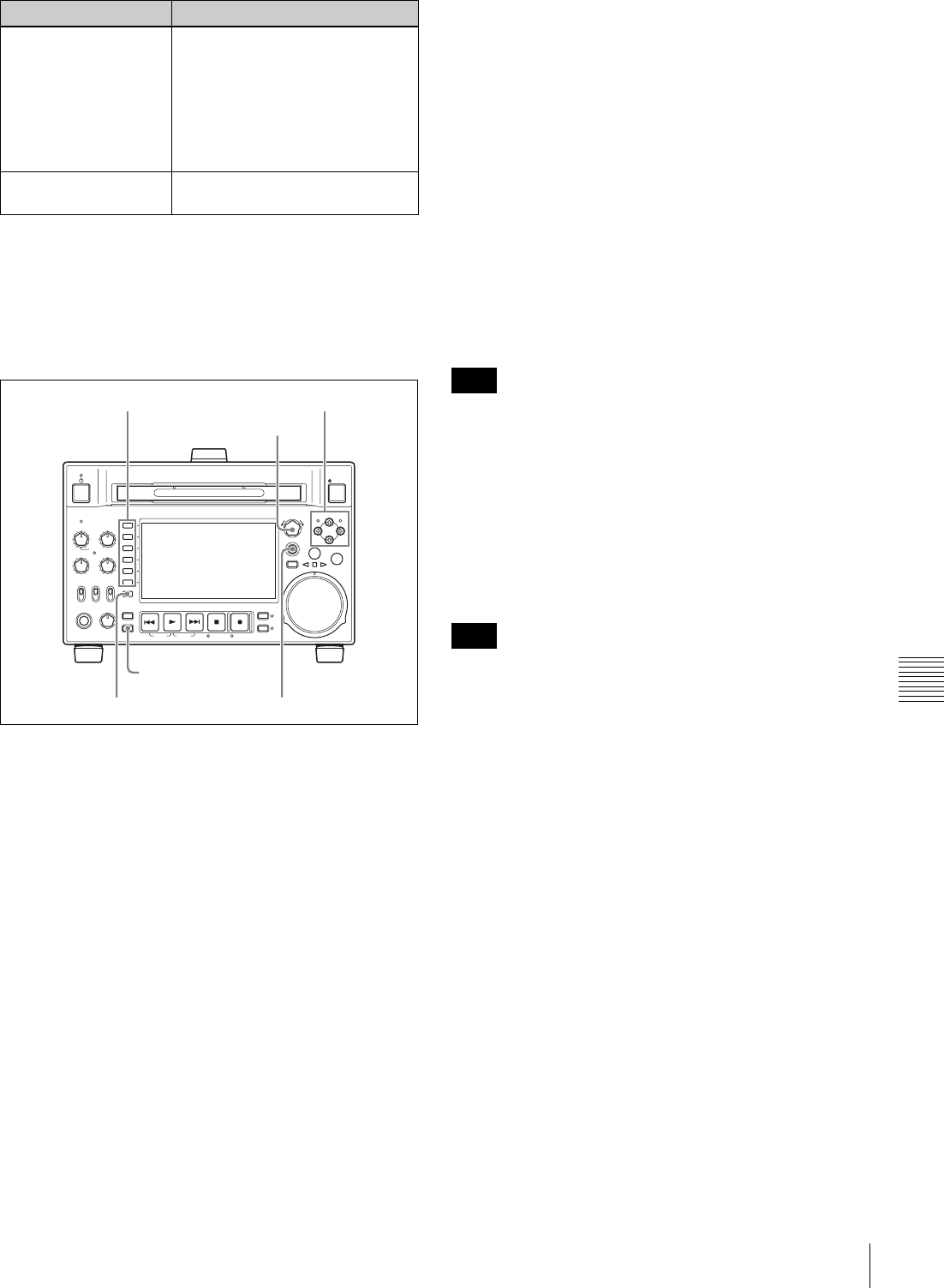
149
Maintenance Menu
Chapter 7 Menus
To change a menu item setting
Carry out the following operations to change the setting.
For information about how to change network settings see
next section “To change network settings”.
1
Use the PUSH SET(S.SEL) knob or the V/MARK1
and v/MARK2 buttons to select the required item,
then press the PUSH SET(S.SEL) knob or the
SELECT function button (F2).
The sub-items of the selected item appears.
2
Select a sub-item with the same operation as step 1,
and use the PUSH SET(S.SEL) knob or the V/MARK1
and v/MARK2 buttons to change the setting.
3
Press the PUSH SET(S.SEL) knob or the SELECT
function button (F2) to confirm the setting change.
4
Press the SAVE function button (F5).
The message “NOW SAVING...” appears on the video
monitor display, and “Saving...” appears in the time
data display area, while the new settings are saved in
memory. When the saving operation is completed, the
video monitor display and the time data display area
return to their normal indications.
To cancel changing a setting
Before pressing the SAVE function button (F5), press the
MENU button.
The menu disappears from the video monitor display,
without saving the new setting.
To change network settings
To change network settings, carry out the procedure
described in the previous section, “To display the
maintenance menu”, to display the NETWORK menu
item, then carry out the following operations.
For details of the settings, consult your network
administrator.
When the IP address is assigned automatically
Check that the network cable is connected to this unit
before carrying out the operation.
Follow the procedure as shown in previous section “To
change a menu item setting” to set maintenance menu item
M5: NETWORK >M50: DHCP to “ENABLE”.
To check the assigned IP address
Select maintenance menu item M5: NETWORK
>M51: IP ADDRESS PRESET.
If the IP address cannot be assigned, this is shown as
“000.000.000.000.” In this case, consult the network
administrator.
To set the IP address
First set DHCP to “DISABLE” (see the previous section,
“When the IP address is assigned automatically”).
1
Select maintenance menu item M5: NETWORK
>M51: IP ADDRESS PRESET.
2
Press the PUSH SET(S.SEL) knob.
The IP address appears, and the digit that can be
changed flashes.
3
Set the IP address.
To select a different digit to be changed
Use the B/IN and b/OUT buttons.
To change the value of a digit
Turn the PUSH SET(S.SEL) knob.
Turning clockwise increases the value, and turning
counterclockwise decreases the value.
The V/MARK1 and v/MARK2 buttons can be used.
Character string at the
right of a menu item Current setting of the menu item
When shown with a colon (:): the
current setting is the same as
the factory default setting.
When shown with a raised dot
(.): the current setting is
different from the factory
default setting.
An * (asterisk) in a
complete list of settings Factory default setting
On-screen indication Meaning
REC
NET
REMOTE
LOCAL
VARIABLE KEY INHI
PRE-
SET
ON
OFF
PB
PHONES LEVEL
SHIFT
DISPLAY
HOME
PAG E
EXPAND
CHAPTER
TOP F REV F FWD END STANDBY REC INHI
PREV NEXTPLAY STOP REC THUMBNAIL
RETURN
PUSH SET(S.SEL)
MENU
RESET
MARK2
MARK1
IN OUT
SHTL/JOG
SUB CLIP
DISC MENU
VAR/JOG
EJECT
ACCESS
CH-1
ALL CH
CH-2
CH-3
CH-4
MENU button
SHIFT button
PAGE/HOME button
Function buttons Arrow buttons
PUSH SET(S.SEL) knob
Note
Note

150 Maintenance Menu
Chapter 7 Menus
To return to the factory default setting
Press the RESET/RETURN button.
4
When all digits are set, press the SAVE function
button (F5).
This returns to the NETWORK menu.
5
Repeat steps 1 to 4 as required, to set the subnet mask
and default gateway.
6
In the NETWORK menu, press the SAVE function
button (F5).
7
When the “NOW SAVING...” message vanishes,
power the unit off and then on again with the on/
standby button.
To set the communications speed and
protocol
Set the communications speed (LINK SPEED) and
communications method (DUPLEX) to match the network
environment.
To set the communications speed and communications
protocol, proceed as explained in the previous section “To
display the maintenance menu” to display the NETWORK
menu and then proceed as follows.
Contact your network administrator if you have any
questions about the proper settings for these items.
To set the communications speed
1
Select maintenance menu item M5: NETWORK
>M54: LINK SPEED.
2
Press the PUSH SET(S.SEL) knob.
The communications speeds (AUTO, 10Mbps,
100Mbps, and 1000Mbps) appear, and the arrow
flashes.
3
Press the PUSH SET(S.SEL) knob or use the v/
MARK1 or V/MARK2 button to select a
communications speed.
To return to the factory default setting
Press the RESET/RETURN button.
4
Press the SAVE function button (F5).
This returns to the NETWORK menu.
To set the communications protocol
1
Select maintenance menu item M5: NETWORK
>M55: DUPLEX.
2
Press the PUSH SET(S.SEL) knob.
The communications protocols (AUTO, Full Duplex,
Half Duplex) appear, and the arrow flashes.
3
Press the PUSH SET(S.SEL) knob or use the V/
MARK1 or v/MARK2 button to select a
communications protocol.
To return to the factory default setting
Press the RESET/RETURN button.
4
Press the SAVE function button (F5).
This returns to the NETWORK menu.

151
Overview
Chapter
Chapter 8 Planning Metadata
8
Planning Metadata
Overview
Planning metadata is a file that contains metadata about the
clips to be shot and recorded.
To use planning metadata, you will need to save a file in
advance in one of the locations shown below, and insert
the media into this unit. (Up to 99 planning metadata files
can be saved on one Professional Disc or USB Flash
drive.)
Professional Disc: General/Sony/Planning directory 1)
USB Flash drive: General/Sony/Planning directory
1) Created automatically when a disc is formatted.
Manipulating planning metadata
This unit allows you to perform the following operations
on planning metadata using the GUI screen.
• To load planning metadata files
• To sort planning metadata
• To check planning metadata properties
• To clear planning metadata
• To switch the title display in the video monitor screen
See “Using planning metadata” (page 92) for details.
To set clip names by using planning
metadata
The following two types of clip name strings can be
written in a planning metadata file.
• The ASCII format name that appears in the video
monitor screen 1)
• The UTF-8 format name that is actually registered as the
clip name 2)
1) It is also possible to display the UTF-8 format name, or no name (see
page 93).
2) When no UTF-8 format name string is specified, the ASCII format name
string is registered as the actual clip name.
By loading a file from one of the following locations into
the unit’s memory before starting to record, you can
register the names in the file as clip names.
There are two ways to load files.
• Automatically load a file that has been written to the
following directory on a Professional Disc via an FTP or
FAM connection.
• Use a GUI screen to load a file that has been written to
the following directories on a Professional Disc or a
USB flash drive (see page 92).
File creation rules
a) General/Sony/Planning directory is created automatically when a disc is
formatted. Automatically when a disc is formatted.
Do not save more than 100 planning metadata files in the
above save locations. The unit may fail to load the files
correctly if more than 100 are saved.
Clip name string format
In a text editor, modify the two fields in the <Title> tag that
contain the clip name strings (the shaded fields in the
example below).
Enter a name in the first field in ASCII format (up to 13
characters), and enter another name in the second field in
UTF-8 format (up to 52 characters).
Clip name string example
<?xmlspversion="1.0"spencoding="UTF-8"?>3
<PlanningMetadataspxmlns="http://
File location File name
Professional Disc:
General/Sony/Planning
directory a)
• Format that can be used
in the General directory
(see page 107)
•Extension: XML
USB memory:General/
Sony/Planning
directory
• ASCII characters (up to
63 characters including
the extension)
•Extension: XML
Note

152 Overview
Chapter 8 Planning Metadata
xmlns.sony.net/pro/metadata/
planningmetadata"spassignId="
P0001"spcreationDate="
2008-01-20T17:00:00+09:00"splastUpdate="
2008-03-28T10:30:00+09:00"spload="
false"spversion="1.00">3
<PropertiessppropertyId="
assignment"spupdate="2008-01-20T09:00:
00+09:00"spmodifiedBy="Chris">3
<TitlespusAscii=" "spxml:lang="
en"> </Title>3
</Properties>3
</PlanningMetadata>3
In the above example, sp indicates a space and 3 indicates
a carriage return.
• When creating a file, write each line as a single
statement, inserting carriage returns only at the indicated
carriage return locations, and inserting no unspecified
spaces.
• If the UTF-8 format string is longer than 52 characters,
the ASCII format string is used as the clip name string.
Setting clip names
1
Load a planning metadata file containing clip names
into the unit’s memory (see page 92).
2
Carry out steps 2 to 5 of to set the “To assign clip
names on this unit” (page 109).
3
Turn the PUSH SET(S.SEL) knob to display “PLAN”,
and then press the PUSH SET(S.SEL) knob.
Each time that you start recording, the unit
automatically creates clip names using the names
specified in the planning metadata file. An underscore
(_) and a three-digit serial number (001 to 999) is
appended to each clip name.
Examples of automatically generated clip names
Clip names displayed in the video monitor screenr:
Typhoon_001, Typhoon_002, ...
The actually recorded clip names:
Typhoon_Strikes_Tokyo_001,
Typhoon_Strikes_Tokyo_002, ... 1)
1) When display of the ASCII format clip name has been selected (see
page 93).
• The serial numbers return to 001 on the next recording
operation if you reach number 999.
• Serial numbers are not reset when you power the unit off
or exchange discs (newly generated numbers are
continuous on the old ones).
• If the ASCII format clip name string is longer than 14
characters, it is displayed in the viewfinder as the first 8
characters + x (abbreviated) + the last 4 characters, for
a total of 13 characters.
Setting essence mark names by
using planning metadata
You can use planning metadata to specify user-defined
names for the Shot Mark0 to Shot Mark 9 essence marks
that correspond to the 0 to 9 keys on a USB keyboard.
When planning metadata that contains user-defined
essence mark name strings is loaded into this unit’s
memory, the unit displays those names for the essence
marks that correspond to the keys and that are recorded
when the keys are pressed.
See page 55 for more information about recording essence
marks, and see page 151 for more information about how
to load files.
Essence mark name string format
Use a text editor to enter essence mark names in the
sections indicated by shading in “Essence mark name
string example”. Names can be either in ASCII format (up
to 32 characters) or UTF-8 format (up to 16 characters).
If a name string contains even one non-ASCII character,
the maximum length of that string is 16 characters.
Essence mark name string example
<?xmlspversion="1.0"spencoding="UTF-8"?>3
<PlanningMetadata xmlns="http://xmlns.sony.net/pro/
metadata/planningmetadata"spassignId="H00123"sp
creationDate="2009-04-15T08:00:00Z"splastUpdate=
"2009-04-15T15:00:00Z"spversion="1.00">3
<Properties propertyId="assignment"spclass=
"original"spupdate="2009-04-15T15:00:00Z"sp
modifiedBy="Chris">3
<Title usAscii="Football Game"spxml:lang=
"en">Football Game 15/04/2009</Title>3
<Meta name="_ShotMark1"spcontent=
""/>3
<Meta name="_ShotMark2"spcontent=
""/>3
<Meta name="_ShotMark3"spcontent=
""/>3
<Meta name="_ShotMark4"spcontent=
""/>3
<Meta name="_ShotMark5"spcontent=
""/>3
Notes
Notes
Typhoon
Typhoon_Strikes_Tokyo
Note
Goal
Shoot
Corner Kick
Free Kick
Goal Kick

153
Overview
Chapter 8 Planning Metadata
<Meta name="_ShotMark6"spcontent=
""/>3
<Meta name="_ShotMark7"spcontent=
""/>3
<Meta name="_ShotMark8"spcontent=
""/>3
<Meta name="_ShotMark9"spcontent=
""/>3
<Meta name="_ShotMark0"spcontent=
""/>3
</Properties>3
</PlanningMetadata>3
In the above example, sp indicates a space and 3 indicates
a carriage return.
You can check user-defined essence mark name strings in
the User Defined Essence Marks screen (see page 93).
When you create a definition file, enter each statement as
a single line with a CRLF only after the last character in the
statement line, and do not enter spaces except where
specified, except within essence mark name strings.
Note
Foul
PK
1st Half
2nd Half
Kick Off

154 Important Notes on Operation
Appendix
Appendix
Important Notes on
Operation
Use and storage
Do not subject the unit to severe shocks
The internal mechanism may be damaged or the body
warped.
Do not cover the unit while operating
Doing so will cause temperatures to rise inside the unit,
possibly resulting in failure.
After use
Turn off the on/standby button.
If you plan not to use the unit for a long time, turn off the
POWER switch on the rear panel as well.
Shipping
• Remove the disc before transporting the unit.
• If sending the unit by truck, ship, air or other
transportation service, pack it in the shipping carton of
the unit.
Care of the unit
If the body of the unit is dirty, clean it with a soft, dry cloth.
In extreme cases, use a cloth steeped in a little neutral
detergent, then wipe dry. Do not use organic solvents such
as alcohol or thinners, as these may cause discoloration or
other damage to the finish of the unit.
In the event of operating problems
If you should experience problems with the unit, contact a
Sony service representative.
Use and storage locations
Store in a level, ventilated place. Avoid using or storing the
unit in the following places.
• In excessive heat or cold (operating temperature range:
5°C to 40°C (41°F to 104°F))
Remember that in summer or in warm climates the
temperature inside a car with the windows closed can
easily exceed 50°C (122°F).
• In damp or dusty locations
• Locations where the unit may be exposed to rain
• Locations subject to violent vibration
• Near strong magnetic fields
• Close to radio or TV transmitters producing strong
electromagnetic fields.
• In direct sunlight or close to heaters for extended periods
To prevent electromagnetic interference from
portable communications devices
The use of portable telephones and other communications
devices near this unit can result in malfunctions and
interference with audio and video signals.
It is recommended that the portable communications
devices near this unit be powered off.
Condensation
If you move the unit from a very cold place to a warm
place, or use it in a damp location, condensation may form
on the optical pickup. Then, if the unit is operated in this
state, recording and playback may not be performed
properly.
Do the following to prevent this from happening.
• When you move or operate the unit in an environment
where condensation may form, be sure to insert a disc in
advance.
• Whenever you turn on the on/standby button, check that
the HUMID indicator does not appear on the color LCD.
If it appears, wait until it disappears before inserting a
disc.
About the LCD panel
LCD panels are manufactured with extremely high
precision technology that yields effective pixel rates of
99.99% or higher. However, very rarely, one or more
pixels may be permanently dark or permanently lit in
white, red, blue, or green.

155
Periodic Maintenance
Appendix
This phenomenon is not a malfunction. Such pixels have
no effect on the recorded data, and the unit may be used
with confidence even if they are present. Periodic Maintenance
Digital hours meter
The digital hours meter can provide eight items of
information about the operational history of the unit. The
information can be displayed in the time data display area
and also, by text superimposition, on the monitor
connected to the unit. Use the information as a guide in
scheduling periodic maintenance.
For periodic maintenance, consult a Sony service
representative.
Display modes of the digital hours meter
H01: OPERATION HOURS mode
Displays the total number of hours the unit has been
powered on in units of 1 hour.
H02: LASER PARAMETER 0 mode (not
resettable)
Of the two optical heads, this shows a counter of the
cumulative light output time by one optical head in units of
hours. 1)
This can be used as a guide in determining when to replace
the optical head.
1) The counter advances at different rates during recording and playback. It
is also affected by the ambient temperature.
H03: LASER PARAMETER 1 mode (not
resettable)
Same as H02.
Of the two optical heads, this shows a counter of the
cumulative light output time by the other optical head in
units of hours. 1)
1) The counter advances at different rates during recording and playback. It
is also affected by the ambient temperature.
H11: OPERATION HOURS mode (resettable)
Same as H01 except that the count is resettable.
This can be used as a guide in determining when to replace
parts.
H13: SEEK RUNNING HOURS 0 mode (resettable)
Of the two optical heads, this shows the cumulative seek
operation time for one optical head in units of hours. The
count is resettable.
This can be used as a guide in determining when to replace
the seek motor.
H14: SPINDLE RUNNING HOURS mode
(resettable)
This shows the cumulative spindle rotation time, in units of
hours. The count is resettable.

156 Periodic Maintenance
Appendix
This can be used as a guide in determining when to replace
the spindle motor.
H15: LOADING COUNTER mode (resettable)
Display the total number of times disc has been loaded in
the unit. The count is resettable.
H17: SEEK RUNNING HOURS 1 mode (resettable)
Same as H13.
Of the two optical heads, this shows the cumulative seek
operation time for the other optical head in units of hours.
The count is resettable.
To display the digital hours meter
Press the MENU button to display the setup menu, then
turn the PUSH SET(S.SEL) knob to display the required
item in the time data display area and on the monitor
connected to the unit.
To exit from the digital hours meter
Press the RETURN function button (F1) to return to the
setup menu.
Press the EXIT function button (F5) to return to the screen
that was displayed before you entered the setup menu.

157
Troubleshooting
Appendix
Troubleshooting
Alarms
An alarm (warning message) appears in the time data
display area when an operation is attempted which is
inappropriate for the settings on this unit or the state of the
disc. Both the alarm message and the action to take to
resolve the problem appear in the monitor video section
and on the screen of the external video monitor connected
to the unit.
When an alarm is displayed, remove the alarm cause by
following the action to take. If the alarm display does not
disappear, contact a Sony service representative.
Please note that there are some alarms which do not appear
depending on the setting of setup menu item 016 ALARM
DISPLAY (see page 124).
See page 126 for more information about setup menu
operations.
When the unit is powered on
REMOTE!
ALARM
REMOTE MODE IS SELECTED.
SET REMOTE/LOCAL/NETWORK
SWITCH TO LOCAL.
Example alarm in time data display area
Example alarm in monitor video section
Alarm message in time
data display area Alarm message in video monitor screen Description/action
ADJ. Mode! THE UNIT IS IN ADJUSTMENT MODE.
CHECK THE SWITCHES OF S2701 ON THE
HPR-23 BOARD AND S1 ON THE VPR-99
BOARD.
This appears when the unit is in adjustment
mode.
Contact a Sony service representative.
MENU Ver.UP THE SETUP MENU SOFTWARE HAS BEEN
UPGRADED.
SET THE SETUP MENU ITEMS TO THE
DESIRED SETTINGS.
Reset the settings in the setup menu (see
page 127).
ILL. SETUP! INVALID SETTINGS SELECTED IN SETUP
MENU.
SET ITEMS IN THE SETUP MENU TO THE
APPROPRIATE VALUES. CONTACT SERVICE
IF THIS ALARM APPEARS AGAIN AFTER
ABOVE PROCEDURE.
Reset the settings in the setup menu (see
page 127). If the same message appears after
you reset the settings, contact a Sony service
representative.
Exchg batt! BATTERY NEEDS REPLACING. PLEASE
CONTACT SERVICE. The NVRAM battery is exhausted. Contact a
Sony service representative.
Update Err! RUN SOFTWARE UPDATE PROGRAM. The software version is not properly updated.
Update the software version again. If the same
message appears after you update the software
version, contact a Sony service representative.
158 Troubleshooting
Appendix
When a disc is inserted
During front panel operations
Alarm message in time
data display area Alarm message in video monitor screen Description/action
Unknown FS! UNKNOWN FILE SYSTEM.
PLEASE FORMAT DISC OR EJECT. Format the disc, or eject it (see page 94).
No FS! NO FILE SYSTEM.PLEASE EJECT DISC. Eject the disc.
ILL. Disc! IRREGULAR DISC IS USED.
USE PROFESSIONAL DISC. Use a Professional Disc.
IRREGULAR DISC IS USED.
PLEASE EJECT DISC.
Salvage NG! CLIP SALVAGE WAS NOT COMPLETED. See “Handling of discs when recording does not end
normally (salvage functions)” (page 58).
Salvage XXXX DISC CANNOT BE RECORDED.
FORMAT DISC OR CONTACT SERVICE
TO RUN CLIP SALVAGE PROGRAM.
(XXXX)
Over DUR! EXCESSIVE DURATION IS IN DISC.
RECORDING AND PLAYBACK IS NOT
POSSIBLE.
Data in excess of the rated capacity is recorded on
the disc.
No Support! FORMAT NOT SUPPORTED.
RECORDING AND PLAYBACK IS NOT
POSSIBLE.
A disc in an unsupported recording format is loaded.
Use a disc in a format supported by this unit.
ILL. Index! INDEX FILE ERROR.
PLEASE FORMAT DISC OR EJECT. Format the disc, or eject it (see page 94).
Formatting! AUTO FORMATTING IS EXECUTING. Wait until the format has been completed and try
again.
FORMAT NG! AUTO FORMATTING WAS NOT
COMPLETED. Eject the disc and insert it again, or insert another
disc.
DI read err CANNOT READ DISC INFORMATION.
PLEASE EJECT DISC.
Read err
DRV ADJ err CANNOT PERFORM AUTO DRIVE
ADJUSTMENT.
Alarm message in time
data display area Alarm message in video monitor screen Description/action
KEY INHI.! a) KEY INHIBIT MODE IS SELECTED.
SET KEY INHIBIT SWITCH TO OFF. This appears when the KEY INHI switch is “on”.
Set the KEY INHI switch to “off”.
REMOTE! a) REMOTE MODE IS SELECTED.
SET REMOTE/LOCAL/NETWORK
SWITCH TO LOCAL.
Set the remote control switch to “LOCAL”.
No Disc! a) NO DISC. Insert a disc and try again.

159
Troubleshooting
Appendix
REC INHI.! AUTO FORMATTING WAS NOT
COMPLETED.
THE DISC WRITE PROTECT TAB IS SET
TO SAVE.
PLEASE EJECT DISC.
Set the disc’s Write Inhibit tab to enable recording
(see page 53).
THE DISC WRITE PROTECT TAB IS SET
TO SAVE.
AUTO FORMATTING WAS NOT
COMPLETED.
REC INHIBIT MODE IS SELECTED.
CHECK FUNCTION MENU.
PLEASE EJECT DISC.
This appears when REC INH on the HOME page of
the function menu is set to “ON”.
Set REC INH to “OFF” (see page 48).
REC INHIBIT. This appears if you press the REC button when a disc
error has occurred. Correct the disc error and try
again.
No Clip! b) NO CLIP. This appears when a playback, search or delete
operation is attempted on a disc with no clips
recorded on it.
Insert a disc with clips recorded on it.
Disc Top! a) DISC TOP. This appears if you press the PREV button or conduct
a high-speed reverse search when the unit is stopped
at the start of the disc.
Use forward search or playback instead.
Disc End! a) DISC END. This appears if you press the NEXT button or conduct
a forward high-speed search when the unit is stopped
at the end of the disc.
Use reverse search or playback instead.
Clip Top! CLIP TOP. This appears in single clip playback mode if you
execute a reverse search when the unit is stopped at
the first frame of a clip. To move to another clip, press
the PREV, NEXT, SHIFT + PREV, or SHIFT + NEXT
button, or perform a thumbnail search.
Clip End! CLIP END. This appears in single clip playback mode if you
execute a forward search when the unit is stopped at
the last frame of a clip. To move to another clip, press
the PREV, NEXT, SHIFT + PREV, or SHIFT + NEXT
button, or perform a thumbnail search.
MAX # Clips DISC CANNOT BE RECORDED TO.
FOR MORE RECORDING, DELETE
SOME CLIPS.
Delete unneeded clips, or insert a disc with enough
free space.
MAX # Files DISC CANNOT BE RECORDED TO.
FOR MORE RECORDING SPACE,
DELETE CLIPS OR NON-AV DATA.
(GENERAL FILES)
Delete clips or GENERAL files.
Disc Full! DISC FULL.
FOR MORE RECORDING, DELETE
SOME CLIPS.
Delete unneeded clips, or insert a disc with enough
free space.
MAX# SB CLP b) NO MORE SUB CLIPS CAN BE ADDED
TO CLIP LIST. This appears when an attempt is made to add sub
clips when 300 sub clips have already been
registered.
Limit the creation of sub clips to 300 or fewer.
CL OVER DUR b) DURATION OF ONE CLIP LIST MUST BE
LESS THAN 24 HOURS. This appears when you try to add a sub clip when the
total duration of sub clips in a clip list has already
reached 24 hours.
Create clip lists so that the total duration is within 24
hours.
Alarm message in time
data display area Alarm message in video monitor screen Description/action

160 Troubleshooting
Appendix
Run Salvage EXECUTE SALVAGE PROGRAM. This appears when recording, E-E display, essence
mark recording, or sub clip addition for quick scene
selection is attempted on a disc that needs to be
salvaged.
Try again after salvaging the clips on the disc (see
page 58).
CNT mode! a) COUNTER MODE IS SELECTED.
SET COUNTER SELECT MENU TO TC
OR UB.
This appears when CNTR SEL on the HOME page of
the function menu is set to “COUNTER”, and you try
to preset timecode or user bits.
To use timecode or user bits, set CNTR SEL to “TC”
or “UB” (see page 48).
TC EXT! b) TC EXTERNAL IS SELECTED.
SET TC INTERNAL MODE IN FUNCTION
MENU.
This appears when TCG on page P5 TC of the
function menu is set to “EXT”, and you try to preset
timecode or user bits by setting PRST/RGN to
“PRESET”.
Set TCG to “INT” (see page 51).
REGEN mode! a) TCG REGEN MODE IS SELECTED.
SET TC PRESET MODE IN FUNCTION
MENU.
This appears when PRST/RGN on page P5 TC of the
function menu is set to “TC” or “VITC”, and you try to
preset timecode or user bits.
Set PRST/RGN to “PRESET” (see page 51).
REC RUN! a) TCG RUN MODE IS SET TO REC RUN.
SET TC FREE RUN MODE IN FUNCTION
MENU.
This appears when RUN MODE on page P5 TC of
the function menu is set to “REC RUN”, and you try to
preset timecode or user bits.
Set RUN MODE to “FREE RUN” (see page 51).
REC mode! b) THUMBNAIL(S) CANNOT BE
DISPLAYED DURING RECORDING. Stop recording and try again.
CANNOT EXECUTE IN REC MODE.
DRIVE MAINTENANCE MENU CANNOT
BE EXECUTED WHILE IN REC MODE.
INPUT SELECTION CANNOT BE
CHANGED DURING RECORDING.
AUDIO REC MODE CANNOT BE
CHANGED DURING RECORDING.
REC-PAUSE! TC/UB CANNOT BE PRESET IN REC-
PAUSE MODE. Stop recording and try again.
Disc Exchg! EXIT DISC EXCHANGE CACHE MODE. This appears when you perform one of the following
operations.
• Attempt to preset timecode or user bits.
• Attempt to make a FAM connection.
• Press the button such as PLAY button while the
disc is being ejected during disc exchange.
No SEL List b) CLIP LIST IS NOT SELECTED. This appears when you press the SUB CLIP/
DISC MENU button while the clip list on the disc is
not loaded into the current clip list.
Load the clip list (see page 86) and try again.
SB CLP mode b) TO ADD AN ESSENCE MARK, EXIT
FROM SUB CLIP MODE FIRST. This appears when an attempt is made to manipulate
the essence mark while the SUB CLIP/DISC MENU
indicator is lit or to set a clip flag while the clip list is
being played back (SUB CLIP indicator is lit). Perform
the operation after pressing the SUB CLIP/DISC
MENU button to turn it off.
SUB CLIP NG b) SUB CLIP IS INVALID.
SET APPROPRIATE IN/OUT POINTS. Set the In and Out points again.
No List! b) NO CLIP LIST. This appears when you try to delete a clip list when
there is no clip list saved on the disc.
Load the disc that contains the clip list you want to
delete.
Alarm message in time
data display area Alarm message in video monitor screen Description/action

161
Troubleshooting
Appendix
Loading List! LOADING CLIP LIST. This appears if the SUB CLIP/DISC MENU button is
pressed while a clip list is loading.Wait for the clip list
to finish loading and try again.
STOP ONCE! b) STOP ONCE, THEN EXECUTE. This appears when the SUB CLIP/DISC MENU
button is pressed while the clip list is being played
back or when an attempt is made to open the GUI
screen with setup menu item 151 GUI OPERATION
set to “stop”. Perform the operation after stopping
playback.
No EM space ESSENCE MARK NOT RECORDED.
NO SPACE AVAILABLE TO RECORD
ESSENCE MARK.
Use the PDZ-1 Proxy Browsing Software to delete
unneeded essence marks.
Or, delete unneeded shot marks in the chapter
thumbnail screen.
EM Full! NO MORE ESSENCE MARKS CAN BE
RECORDED.
Disc Damage DISC CANNOT BE RECORDED TO.
USE ANOTHER DISC FOR RECORDING. Use another disc.
NON-AV Full DISC CANNOT BE RECORDED TO.
FOR MORE RECORDING SPACE,
DELETE NON-AV DATA. (GENERAL
FILES)
Delete unneeded GENERAL files.
Index File! UNSUPPORT INDEX FILE.
DISC CANNOT BE RECORDED TO. Use another disc.
File System CURRENT VERSION OF THE
SOFTWARE SETS THE DISC WRITE
PROTECTED.
This appears when you insert a disc that can be
played back but not recorded.
Exchange the disc for one with a file system
supported by this unit. Or format the disc (see
page 94).
FILE SYSTEM ON THE DISC INHIBITS
WRITING.
Loading! a) LOADING. This appears if you press a button while a disc is
loading. Wait until the disc has finished loading and
try again.
Unloading! a) UNLOADING. This appears if you press a button while a disc is
unloading.
Wait until the disc has finished unloading and try
again.
Clip lock! CLIP IS LOCKED.
UNLOCK CLIP IN THUMBNAIL MENU. This appears when an operation is attempted on a
locked clip, or when an edit preset command is
received for such a clip. Use the Thumbnail Menu to
unlock the clip (see page 83) and try again.
File Access CANNOT CHANGE SETTINGS DURING
FILE ACCESS. This appears when an attempt is made to change the
setting of PC RMT (ENABLE/DISABLE) on page P7
OTHER of the function menu while accessing a file or
processing the command with PC REMOTE.
Inhibit! PC REMOTE IS DISABLED.
CHECK MAINTENANCE MENU M33. This appears when an attempt is made to change the
setting of PC RMT (ENABLE/DISABLE) on page P7
OTHER of the function menu while maintenance
menu item M33: FILE I/F CONFIG >PC REMOTE is
set to “ENABLE”.
PC REMOTE IS DISABLED.
CHECK SETUP MENU 215. This appears when an attempt is made to change the
setting of PC RMT (ENABLE/DISABLE) on page P7
OTHER of the function menu while setup menu item
215 i.LINK mode is set to the value other than “FAM”.
GUI Inhibit GUI OPERATION IS INHIBITED.
CHECK SETUP MENU. This appears when the THUMBNAIL button or the
DISC MENU (SHIFT+SUB CLIP) button is pressed
while setup menu item 151 GUI OPERATION is set to
“dis”.
Alarm message in time
data display area Alarm message in video monitor screen Description/action

162 Troubleshooting
Appendix
a) Displayed only when setup menu item 016 ALARM DISPLAY is set to
“on”.
b) Displayed only when setup menu item 016 ALARM DISPLAY is set to
“on” or “limit”.
Mixed REC! THIS DISC CANNOT BE RECORDED.
TWO OR MORE AUDIO OR VIDEO
FORMATS ARE RECORDED ON THE
DISC.
This appears if a disc containing clips recorded in
different recording formats is inserted while mixed
format recording mode is disabled. Enable mixed
format recording mode, or insert another disc.
Mixed REC! b) DISC CANNOT BE EDITED.
MIXED AUDIO/VIDEO MODE ON DISC. This appears when an edit preset command is
received, but the inserted disc contains clips with
mixed recording formats.
Exchange the inserted disc for a disc that does not
contain clips with mixed recording formats.
Resolution THIS CLIP CANNOT BE ADDED.
THE CLIP’S RESOLUTION DOES NOT
MATCH THE CLIP LIST’S RESOLUTION.
Clips can be registered in clip lists only if their
resolution (number of system lines) matches the
resolution of clips in the clip list.
i.LINK! b) CANNOT EDIT AV MATERIAL WHEN
INPUT SIGNAL IS VIA i.LINK. This appears when an edit preset command is
received, but “i.LINK” is selected as the input signal.
Under V INPUT on the P1 VIDEO page of the
function menu, select a signal other than “i.LINK”.
SD Input! b) CANNOT EDIT AV MATERIAL WHEN
INPUT SIGNAL IS VIA SD-SDI. This appears when an edit preset command is
received, but the recording format is set to HD422
and “SDSDI” is selected as the video input signal.
Under V INPUT on the P1 VIDEO page of the
function menu, select “HDSDI”.
NON-AUDIO! b) AUDIO INSERT EDITING WITH
INDEPENDENT CHANNELS IS NOT
POSSIBLE.
CHANGE ‘NON-AUDIO INPUT’ IN
MAINTENANCE MENU FROM ‘DATA’ TO
‘AUDIO’.
This appears when digital audio signals are set to
“data” and an edit preset command is received for
individual channels in the audio input channel pairs
(CH1/2, CH3/4, CH5/6, CH7/8). To perform insert
editing of non-audio signals, always operate on
channel pairs.
If you want to perform insert editing of the audio of
individual channels from channel pairs, set
maintenance menu item M37: AUDIO CONFIG
>M372: NON-AUDIO INPUT to “audio”.
List Exists DISC CANNOT BE EDITED.
DELETE ALL CLIP LIST BEFORE
BEGINNING DESTRUCTIVE EDITING.
This appears when an edit preset command is
received but the inserted disc contains a clip list.
Exchange the disc for one that does not contain a clip
list, or delete all clip lists from the disc.
N/A Clip! b) CANNOT EDIT AV MATERIAL.
CHECK REC FORMAT IN CLIP. This appears when an edit preset command is
received for an HD420 clip or another clip that cannot
be edited.
Check the recording format of the edit target clip (see
page 59).
Mode Err! b) CANNOT EDIT AV MATERIAL.
CHANGE ‘SNGL CLIP PB’ TO ‘OFF’ AND
‘REC MODE’ TO ‘NORMAL’ IN SETUP
MENU.
This appears when an edit preset command is
received but the unit is in Single Clip Playback mode,
Disc Exchange Cache mode, or Clip Continuous Rec
mode.
Set setup menu item 154 SINGLE CLIP PLAY MODE
to “off”, or set setup menu item 150 REC MODE to
“normal”.
N/A Disc! b) DISC CANNOT BE EDITED.
USE PFD23A OR PFD50DLA. This appears when an edit preset command is
received, but linear editing is not possible for the
inserted disc.
Insert a disc that can be edited by linear editing (see
page 60).
Alarm message in time
data display area Alarm message in video monitor screen Description/action

163
Troubleshooting
Appendix
During recording and editing operations
a) Displayed only when setup menu item 016 ALARM DISPLAY is set to
“on” or “limit”.
During playback
Alarm message in time
data display area Alarm message in video monitor screen Description/action
Input Sig!” a) VIDEO INPUT SIGNAL DOES NOT
MATCH SYSTEM SETUP. This appears when the signal that does not
correspond to the system frequency or the number of
lines set in this unit is being input, or when HDSDI or
i.LINK TS is selected as a video input signal while
setting the SD signal recording.
Input a signal that matches the system frequency, or
change this unit’s system frequency setting (see
page 43).
ILL. REC! a) ENCODING DOES NOT SYNCHRONIZE
WITH REF VIDEO. Check the signals being input to this unit.
ILL. REF! a) INPUT VIDEO SIGNAL DOES NOT
SYNCHRONIZE WITH REF VIDEO
SIGNAL.
USE COMMON REFERENCE SIGNAL
OR CONNECT RECORDER REF OUT TO
PLAYER REF IN.
Input a reference signal synchronized with this unit’s
system frequency.
MEM. Full! a) MEMORY FULL !! Check the disc being recorded by this unit.
Verify ERR! DISC ERROR DETECTED. This appears when an error is found in the signal
recorded on the disc while performing the recording
verification function. Change the disc.
Recording NOW RECORDING ... Wait for recording to finish.
Cache Full! CACHE FULL.
DATA IS BEING OVERWRITTEN. This appears when the memory becomes full while
performing the disc exchange cache function.
Change the disc immediately.
Clip End! EDITING ACROSS MULTIPLE CLIPS IS
NOT POSSIBLE. This appears when an edit across multiple clips is
attempted.
It is not possible to edit across multiple clips.
Disc Full! DISC FULL.
FOR MORE RECORDING, DELETE
SOME CLIPS.
This appears when the free capacity of the disc is
exhausted during assemble editing.
Delete unneeded clips, or exchange the disc for one
with enough free capacity.
REC Format! a) REC MODE SELECTION DIFFERENT
FROM AUDIO/VIDEO ON DISC.
MATCH REC MODE SELECTION WITH
CLIP.
This appears when editing of mixed recording formats
is enabled and an attempt is made to edit an
underlying clip in a different recording format.
Reset the recording format to match the format of the
editing target clip (see page 60).
Preroll! a) PREROLL TIME SETTING IS SHORT. This appears when editing is impossible because the
preroll time is too short.
Set setup menu item 001 PREROLL TIME to 5
seconds or longer.
Last Clip! a) ASSEMBLE EDITING IS NOT POSSIBLE
BESIDES LAST CLIP. This appears when an attempt is made to perform an
assemble edit on a clip that is not the last clip on the
disc.
Assemble editing is possible only on the last clip.
Alarm message in time data
display section Alarm message in monitor video
section Description/action
ILL. PLAY! a) ILLEGAL PLAYBACK. Check the disc being played by this unit.
MEM. Empty! a) MEMORY EMPTY !! Check the disc being played by this unit.
Disc Error! DISC ERROR DETECTED. Use another disc.

164 Troubleshooting
Appendix
a) Displayed only when setup menu item 016 ALARM DISPLAY is set to
“on” or “limit”.
During thumbnail search, scene selection, and clip list operations
Alarm message in GUI
screen Description/action
Cannot Expand Clip any
Further. The clip cannot be expanded into more blocks.
This appears when the EXPAND button is pressed when the number of block is maximum, or
when the duration of an expanded thumbnail is 1 frame.
Selected Essence Mark does
not Exist. The selected essence mark does not exist.
This appears in the essence mark selection screen when the specified essence mark does not
exist on the disc.
Sub Clip is Invalid.
Set Appropriate IN/OUT
Points.
The temporal relationship between the specified In and Out points in sub clip trimming is not
correct.
Reset so that the value of the Out point timecode is larger than the value of the In point
timecode.
Duration of One Clip List
must be Less than 24 Hours. The total duration of the current clip list is greater than 24 hours.
This appears when the total duration of the current clip list exceeds the upper limit of 24 hours as
the result of adding or trimming sub clups.
No More Sub Clips can be
Added to the Clip List. The upper limit of sub clips in the current clip list has been reached.
This appears when the upper limit of 300 clips in a clip list has been reached as the result of
adding or trimming sub clips.
Sub Clip does not Exist. There are no sub clips in the current clip list.
This appears when an attempt is made to move, trim or delete sub clips or preset timecode.
Clip List does not Exist. There are no clip lists on the disc.
This appears when an attempt is made to execute a Delete Clip List operation when there are no
clip lists on the disc.
Move is Invalid. The sub clip cannot be moved.
This appear when an attempt is made to execute a Move Sub Clips operation when there are no
sub clip in the current clip list, or when there is only one sub clip.
Chapter does not Exist. The specified chapter has not been recorded.
This appears when an attempt is made to display a chapter when a chapter has not been
recorded for that clip.
Some Essence Mark cannot
be Deleted. The essence mark cannot be deleted.
This appears when an attempt is made to delete an essence mark that cannot be deleted with a
Delete Essence Mark operation. Rec Start and Cut essence marks cannot be deleted.
Some Essence Mark cannot
be Moved. The essence mark cannot be moved.
This appears when an attempt is made to move an essence mark that cannot be moved with a
Move Essence Mark operation. Rec Start and Cut essence marks cannot be moved.
Clip is Locked. The clip is locked.
This appears when an attempt is made to delete a clip, set the clip thumbnail, or delete a shot
mark when the clip is locked.
All Clips are Locked. All clips are locked.
This appears when an attempt is made to execute a Lock All Clips operation when all clips are
already locked.
All Clips are Unlocked. All clips are unlocked.
This appears when an attempt is made to execute an Unlock All Clips operation when all clips
are already unlocked.
Command Disabled. This appears when an attempt is made to perform Format Disc operation while Disable “Format
Disc” is set to “Disable”.
A File with the Name you
Specified Already Exists.
Specify a Different Name.
This appears when an attempt is made to set an existing clip name while changing the clip name
using Set Clip Name.
Set NAMING FORM to “free” This appears when an attempt is made to change the clip name using Set Clip Name even
though NAMING FORM is not set to “free” (see page 109).
“No Flash Drive” This appears when an attempt is made to select “USB Flash Drive” in the media selection
screen under Load Planning Metadata/Select Drive even though the USB memory is not
connected.
165
Troubleshooting
Appendix
Alarms relating to audio and video signals
a) Displayed only when setup menu item 016 ALARM DISPLAY is set to
“on”.
Alarms relating to sensors and drives
Not Loaded. This appears when a command related to planning metadata is executed with no planning
metadata loaded.
Load planning metadata and try again.
Syntax Error! This appears when loading of planning metadata fails because of a syntax error. Correct the
syntax error and try loading the metadata again.
Irregular Disc is Used.
Use Professional Disc. This appears when the unit is unable to record or play the inserted disc.
This unit can record and play Professional Discs. Insert a Professional Disc.
The Disc Write Protect TAB
is set to Save. This appears when an attempt is made to format a write-protected disc.
Try formatting the disc after moving the write protect tab away from the Save position.
The REC Inhibit Mode is
Selected.
Check Function Menu.
This appears when an attempt was made to format when function menu item HOME >F3: REC
INH is set to “ON”.
Set F3: REC INH to “OFF” and try formatting again.
Auto Formatting was not
Completed. This appears when auto formatting fails.
Video Resolution Differ from
it on Clip List. This appears when an attempt is made to add a clip to a clip list containing clips with a different
video resolution (number of system lines).
It is not possible to add clips to clip lists containing clips with a different video resolution.
No Clip Meets the Condition. This appears when no clip is found to meet clip filtering conditions.
Alarm message in time
data display area Alarm message in video monitor screen Action
No INPUT! a) INPUT VIDEO IS NOT DETECTED.
CHECK THE VIDEO INPUT MODE AND
SUPPLY A VIDEO SIGNAL TO VIDEO
INPUT.
• Check the setting of V INPUT on Page P1 VIDEO of
the function menu (see page 49).
• Input an HDSDI signal.
EMPHASIS! a) INPUT AUDIO EMPHASIS IS NOT
SUPPORTED.
CHECK THE EMPHASIS OF THE AUDIO
INPUT SIGNAL.
Check the emphasis of the audio input signal.
REF NON-STD A NON-STANDARD REF SIGNAL IS
BEING USED FOR REF VIDEO. USE A
STANDARD SIGNAL.
Input a standard signal.
Alarm message in GUI
screen Description/action
Alarm message in time
data display area Alarm message in video monitor acreen Description/action
FAN Stopped FAN MOTOR STOPPED. Contact a Sony service representative.
Note
The unit will not stop operating, but if you continue to
use it in this state temperatures inside the unit or the
drive will rise, possibly resulting in failure or fire.
DR-FAN Stop DRIVE FAN MOTOR STOPPED.
N-FAN Stop FAN MOTOR ON NET-4 BOARD
STOPPED.
High TEMP! HIGH TEMPERATURE.
HIGH TEMPERATURE IN DRIVE.
HIGH TEMPERATURE ON NET-4 BOARD.
HUMID! MOISTURE HAS BEEN DETECTED. Stop recording or playback, power the unit off and on
again, and wait until the HUMID display disappears.
BATT EMPTY! BATTERY EMPTY! Change the battery.

166 Troubleshooting
Appendix
Alarms related to system frequency and recording format
The following alarms are displayed only when setup menu
item 016 ALARM DISPLAY is set to “on” or “limit”.
Unknown USB UNKNOWN USB DEVICE. The USB connector of this unit is for maintenance
purposes and connection of USB devices. Connect a
compatible USB device.
Alarm message in time
data display area Alarm message in video monitor acreen Description/action
Alarm message in time
data display area Alarm message in video monitor screen Action
1080/59.94i RECORDING AND PLAYBACK IS NOT
POSSIBLE.
SYSTEM SETTINGS DIFFERENT FROM
DISC.
This appears when the system frequency of the unit
differs from that of the loaded disc. Insert a disc with
the same system frequency as the unit, or change the
unit’s system frequency.
1080/29.97P
1080/50i
1080/25P
1080/23.98P
720/59.94P
720/50P
525/59.94i
625/50i
1080/59.94i DISC CANNOT BE RECORDED.
VIDEO RESOLUTION DIFFER FROM IT
ON DISC.
This appears when mixed format recording mode is
disabled and the current system lines setting of this
unit does not match the resolution of the inserted
disc.
Insert a disc with a resolution that matches the
current system lines setting of this unit, or change the
system lines setting of this unit, or enable mixed
format recording mode.
1080/50i
1080/29.97P
1080/25P
1080/23.98P
720/59.94P
720/50P
HD422 1080 DISC CANNOT BE RECORDED.
VIDEO REC MODE SELECTION
DIFFERENT FROM VIDEO ON DISC.
This appears when mixed format recording mode is
disabled, and the video recording format of this unit
does not match the video recording format of the
inserted disc.
Insert a disc with a video recording format that
matches the video recording format of this unit, or
change the video recording format of this unit.
HD422 720
HD420 1080
HD420 720
IMX50 Clip
IMX40 Clip
IMX30 Clip
8CH×16 Clip DISC CANNOT BE RECORDED.
AUDIO REC MODE SELECTION
DIFFERENT FROM AUDIO ON DISC.
This appears when mixed format recording mode is
disabled, and the audio recording format of this unit
does not match the audio recording format of the
inserted disc.
Insert a disc with a audio recording format that
matches the audio recording format of this unit, or
change the audio recording format of this unit.
4CH×24 Clip
2CH×16 Clip
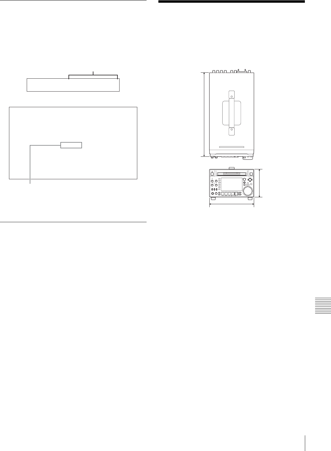
167
Specifications
Appendix
Error messages
Error codes appear in the time data display when an error
(usually a hardware problem) occurs. In addition, both
error messages and error codes appear in the monitor video
section and on the video monitor connected to the unit.
When an error message appears, follow the instructions in
the error message to resolve the problem.
To eject discs with the unit powered
off
As an emergency measure, disc cartridges can be removed
with the unit powered off. This operation should always be
done by a trained service technician.
Specifications
General
External dimensions (w/h/d, excluding projections)
210×132×396 mm (8 3/8×5 1/4×15 5/8
inches)
Mass 6.5 kg (14 lb. 5 oz.)
Power requirements
100 V to 240 V AC, 50/60 Hz
12 V DC
Power consumption
AC operation: 80 W
DC operation: 65 W
(Power saving mode: 55 W)
Peak inrush current
(1) Power ON, current probe method:
45 A (240 V), 18 A (100 V)
(2) Hot switching inrush current,
measured in accordance with
European standard EN55103-1: 11 A
(230 V)
Operating temperature
5ºC to 40ºC (41ºF to 104ºF)
Storage temperature
–20ºC to +60ºC (–4ºF to +140ºF)
Operating relative humidity
25 to 90%
System
Recording/playback format
Video MPEG HD 422: 50 Mbps
Proxy video MPEG-4
Error50-010
ERROR
AN ERROR HAS BEEN
DETECTED. INFORM SERVICE
OF FOLLOWING CODE:
50-010
PRESS EJECT KEY
TO EJECT DISC.
Error code
Error code in time data display area
Error code
Example error in video monitor screen
in mm (inches)
210 (8 3/8)
132 (5 1/4)
396 (15 5/8)

168 Specifications
Appendix
Audio 24 bits, 48 kHz, 8 channels
Proxy audio A-law 8 bits, 8 kHz, 8 channels
Recording/playback times
PFD23A discs Approx. 43 minutes
PFD50DLA discs
Approx. 95 minutes
The recording and playback times listed above are
approximate. Maximum recording times may vary
depending on recording conditions.
Search speed
Jog mode –1 to +1 times normal speed
Variable-speed mode
–2 to +2 times normal speed
Shuttle mode –20 to +20 times normal speed
Fast forward mode
+35 times normal speed
Fast reverse mode
–35 times normal speed
Video performance
Sampling frequency
Y: 74.25 MHz, R–Y/B–Y: 37.125 MHz
Quantization 8 bits/sample
Compression MPEG-2 422P@HL
Composite output
Frequency response
0.5 to 5.75 MHz+0.5/–2.0 dB
S/N (Y) 53 dB or more
Y/C delay ±20 ns or less
K-factor (K2T) 1.0% or less
Processor adjustment range
Video level –∞ to +3 dB
Chroma level –∞ to +3 dB
Set up/black level
±30 IRE/±210 mV
Chroma phase ±30°
System phase SYNC: ±15 µs
SC: 0 to +400 ns
Audio performance
Sampling frequency
48 kHz
Quantization 24 bits
Headroom –20/–18/–16/–12 dB (selectable)
Frequency response
20 Hz to 20 kHz +0.5/–1.0 dB (0 dB at
1kHz)
Dynamic range 90 dB or more
Distortion 0.05% or less (at 1 kHz)
Input connectors
Digital video inputs
SD/HDSDI INPUT
BNC type (×1), complying with SMPTE-
259M (SD)/SMPTE-292M (HD)
(i.LINK) S400
6-pin type (×1), complying with IEEE
1394
Analog video inputs
REF.VIDEO INPUT
BNC type (×2, loop-through), HD Tri-
level sync (0.6 Vp-p/75 Ω/sync
negative), SD black burst, or SD
composite sync (0.286 Vp-p/75 Ω/
sync negative)
Analog audio inputs
ANALOG AUDIO INPUT 1, 2
XLR 3-pin, female (×2), +4 dBu, high
impedance, balanced
Digital audio inputs
DIGITAL AUDIO (AES/EBU) IN 1/2, 3/4
BNC type (×2), 1/2ch, 3/4ch complying
with AES-3id-1995
Timecode input
TIME CODE IN
BNC type (×1), SMPTE timecode, 0.5 to
18 Vp-p, 10 kΩ, unbalanced
Output connectors
Digital video outputs
HDSDI OUTPUT 1, 2(SUPER)
BNC type (×2), complying with SMPTE-
292M
SDSDI OUTPUT 1, 2(SUPER)
BNC type (×2), complying with SMPTE-
259M
Analog video outputs
COMPOSITE OUTPUT 1, 2(SUPER)
BNC type (×2), 1.0 Vp-p, 75 Ω, sync
negative, complying with SMPTE-
170M
Analog audio outputs
ANALOG AUDIO OUTPUT 1, 2
XLR 3-pin, male (×2), +4 dBu, 600 Ω,
low impedance, balanced
AUDIO MONITOR
XLR 3-pin, male (×2), +4 dBu, 600 Ω,
low impedance, balanced
PHONES Stereo phone jack (×1), –∞ to –13 dBu,
8Ω, unbalanced
Note

169
Specifications
Appendix
Digital audio outputs
DIGITAL AUDIO (AES/EBU) OUTPUT 1/2, 3/4
BNC type (×2), 1/2 ch, 3/4 ch complying
with AES-3id-1995
Timecode output
TIME CODE OUT
BNC type (×1), SMPTE timecode,
1.0 Vp-p, 75 Ω, unbalanced
Remote control connectors
REMOTE(9P) D-sub 9-pin, female (×1), complying
with RS-422A
VIDEO CONTROL
D-sub 9-pin, female (×1), complying
with EIA RS-423
REMOTE 4-pin, female (×1)
DC 12 V, 7.5 W
Network RJ-45 type (×1)
1000BASE-T: complying with
IEEE802.3ab
100BASE-TX: complying with
IEEE802.3u
10BASE-T: complying with IEEE802.3
Other
MAINTENANCE connectors
(High Speed USB (USB 2.0) Type-A)
Accessories supplied
Operation manuals
English version (1)
Japanese version (1)
CD-ROM manual (1)
Installation manual (1)
XDCAM Application Software CD-ROM (1)
Connector caps
Accessories not supplied
AC power cord
• For the customers in the U.S.A and Canada
Part number 1-551-812-41 (125 V, 10 A, about 2.4 m)
• For the customers in the United Kingdom
Part number 1-777-823-12 (250 V, 10 A, about 2.0 m)
• For the customers in European countries other than the
United Kingdom
Part number 1-551-631-61 (250 V, 10 A, about 2.0 m)
RCC-G5 9-pin Remote Control Cable
RM-280 Remote Edit Controller
PFD23A Professional Disc
PFD50DLA Dual-layer Professional Disc
BP-L80S Battery Pack
BP-GL95 Battery Pack
BKP-L551 Battery Adaptor
MPEG TS Board
PDBK-201
SD Record And Playback Key
PDBK-S1500
24P Record And Playback Key
PDBK-F1500
Design and specifications are subject to change without
notice.
Notes
• Always make a test recording, and verify that it was
recorded successfully. SONY WILL NOT BE
LIABLE FOR DAMAGES OF ANY KIND
INCLUDING, BUT NOT LIMITED TO,
COMPENSATION OR REIMBURSEMENT ON
ACCOUNT OF FAILURE OF THIS UNIT OR ITS
RECORDING MEDIA, EXTERNAL STORAGE
SYSTEMS OR ANY OTHER MEDIA OR
STORAGE SYSTEMS TO RECORD CONTENT
OF ANY TYPE.
• Always verify that the unit is operating properly
before use. SONY WILL NOT BE LIABLE FOR
DAMAGES OF ANY KIND INCLUDING, BUT
NOT LIMITED TO, COMPENSATION OR
REIMBURSEMENT ON ACCOUNT OF THE
LOSS OF PRESENT OR PROSPECTIVE PROFITS
DUE TO FAILURE OF THIS UNIT, EITHER
DURING THE WARRANTY PERIOD OR AFTER
EXPIRATION OF THE WARRANTY, OR FOR
ANY OTHER REASON WHATSOEVER.
HD1500

170 Using PDZ-1 Proxy Browsing Software
Appendix
Using PDZ-1 Proxy
Browsing Software
When a computer with the PDZ-1 Proxy Browsing
Software installed is connected to this unit, you can
transfer the proxy AV data and metadata files recorded on
a disc to the computer. On the computer side, PDZ-1
enables you to browse the proxy AV data, add or modify
metadata (titles, comments, essence marks, etc.), or create
a clip list.
The modified metadata and the created clip list can then be
written back to the disc loaded in this unit.
For more information about PDZ-1 functions and
operations, refer to the PDZ-1 help.
System requirements
The following are required to use PDZ-1.
• Computer: PC with Intel Pentium M processor, at least 1
GHz (installed memory: at least 512 MB)
• Operating system: Microsoft Windows XP Professional
SP2 or higher, Windows Vista Ultimate/Business
(32 bit)
• Web browser: Internet Explorer 6.0 SP1 or higher
• DirectX: DirectX 8.1b or higher
To install PDZ-1
Insert the supplied XDCAM Application Software CD-
ROM into the CD-ROM drive of your computer, and then
run the installer in the PDZ-1 directory of the CD-ROM.
For details, refer to the ReadMe file contained on the
CDROM disc.
• Make sure that the hard disk drive on which the work
folder to store the material transferred from this unit has
adequate free space.
• To transfer files between the computer and this unit
requires this unit’s IP address and other network-related
settings to be made.
For details of the network-related settings, see “To change
network settings” (page 149).
Notes
171
Using UMID Data
Appendix
Using UMID Data
Metadata is additional information recorded on discs along
with audio-visual data. It is used to bring greater efficiency
to the flow of operations from material acquisition through
editing, and to make it easier to find and reuse material.
As one of application of metadata, the UMID has been
internationally standardized.
What is a UMID?
A UMID (Unique Material Identifier) is a unique i-
dentifier for audio-visual material defined by the
SMPTE-330M-2003 standard.
A UMID may be either as a 32-byte Basic UMID or an
Extended UMID, which includes an additional 32 bytes of
Source Pack to make a total 64 bytes.
For details, refer to SMPTE-330M.
A globally unique ID is automatically recorded for every
clip.
The Extended UMID is metadata that provides additional
information such as location, time/date, company ID and
so on.
The UMID is applied as follows.
Using the Extended UMID
You have to enter a country code, organization code and
user code. Set the country code referring to the table in ISO
3166, and set the organization code and user code
according to the guidelines of your organization.
For details, see “Setting UMID ownership information”
(page 172).
Functions of UMID data
UMID data enables the following:
• Addition of a globally unique ID to every clip of audio-
visual material. The unique ID is used to detect the
material source and to link it with the original source
material.
• Distinguishing between original material and copied
material. 00 is added to the Instance Number for original
material.
Extended UMID (64 bytes)
Basic UMID (32 bytes) Source Pack (32 bytes)
Universal label L Instance
No. Material Number Time/Date Spatial
Coordinates
Country
Org User
12 bytes 13 bytes 16 bytes 8 bytes 12 bytes 4 bytes 4 bytes 4 bytes
Instance No.
Material No.
ID generated when
shooting
Same as the above
Source Pack
Shooting
information (when,
where and who)
Same as the above
Original material: 00 00 00
Copied material: generation number (1 byte)
+ random number (2 bytes)
Distinguish between the
original material and copied
material
Material source ID/
detecting material Metadata pack that
identifies the source of
material unit by defining the
when, where and who of
the material unit with which
it is associated.

172 Using UMID Data
Appendix
• Recording with UTC time. UTC (coordinated universal
time) is used when recording the UMID. Use of a
universal time system enables uniform management of
source material recorded all over the world.
• Calculation of date differences. Source material is
recorded using modified Julian dates (MJD), which
enables easy calculation of date differences between
different source material items.
Setting UMID ownership information
Proceed as follows.
1
Set setup menu item 029 STORE OWNER to “on”
(see page 124).
See page 126 for more information about setup menu
operations.
The STORED OWNERSHIP (UMID ownership
information setting) screen appears.
COUNTRY: Sets the country code.
ORGANIZATION: Sets the organization code.
USER: Sets the user code
See the next item “About the UMID ownership
information” for more information about these codes.
2
Use the PUSH SET(S.SEL) knob to select the item to
set and the character input location, then press the
knob.
3
Use the PUSH SET(S.SEL) knob, – or + function
button (F3 or F4) to select characters to input at the
selected location.
To delete all input data
Press the RESET/RETURN button.
4
Press SAVE function button (F5).
The message “NOW SAVING...” appears, and the
ownership information is saved.
About the UMID ownership information
COUNTRY (country code)
Set the country code by entering an abbreviated
alphanumeric string (4-byte alphanumeric string)
according to the values defined in ISO 3166-1.
There are about 240 country codes.
Find your own country code on the following web page.
Refer to ISO 3166-1:
http://www.iso.org/iso/country-codes/
iso_3166_code_lists.htm
When the country code is less than 4 bytes, the active part
of the code occupies the first part of the 4 bytes and the
remainder must be filled with the space character (20h).
Example: Japan
For Japan, the country code is JP, which is 2 bytes, or JPN,
which is 3 bytes.
Thus, enter the following:
JP_ _
or
JPN _
where _ represents a space.
ORGANIZATION (organization code)
Enter a 4-byte alphanumeric string for the organization
code.
• There are no problems in recording or playing back
audio-video signals, even if the ORGANIZATION is not
set.
• Organization codes must be acquired by applying to the
SMPTE registration office. When no organization code
has been acquired, it is forbidden to enter an arbitrary
string. As a rule, the code “00” must be entered.
Freelance operators who do not belong to an origination
should enter “~”.
USER (user code)
Enter a 4-byte alphanumeric string to identify the user.
The user code is registered with each organization locally.
It is usually not centrally registered.
When the user code is less than 4 bytes, enter the user code
at the beginning of the 4 bytes and fill the remainder of the
string with the space character (20h).
This user code is determined by the organization. The
methods used depend on the organization.
User code cannot be entered when no organization code
has been entered.
RETURN
SELECT
SAVE
SETUP
EXIT
ITEM-029
STORED OWNERSHIP
*COUNTRY -
ORGANIZATION -
USER -
Notes
Note

173
Ancillary Data
Appendix
Ancillary Data
This unit can play and record ancillary data multiplexed
into HDSDI signals. It can also input and output ancillary
data in MXF files when transferring files via FAM or FTP
connections. Transferable auxiliary data includes text data
(captions and metadata) and control signals.
Ancillary data in HDSDI signals
This unit can record and play back closed captions
conforming to the EIA-708-B 1) standard and text data
conforming to the ARIB TRB23 2) which comprise the
VANC (Vertical ancillary data) packets.
1) EIA: Electronic Industries Alliance
2) ARIB: Association of Radio Industries and Businesses
To record ancillary data
In maintenance menu item M3B: VANC RX
PARAMETER, set the lines where ancillary data is
inserted, the DID (Data Identifier word), and the SDID
(Secondary Data Identifier word) (see page 146).
To record EIA-608-B standard closed caption
signals in SDSDI signals after conversion to the
EIA-708-B standard
Set the following items.
• Sub items of maintenance menu item M3B: VANC RX
PARAMETER
- DID (data identification word): 61h
- SDID (secondary data identification word): 01h
• V INPUT on function menu page P1 VIDEO: SDSDI
• Setup menu item 031 RECORDING FORMAT: HD422,
420HQ, or 420SP
VANC packets
• The Japanese ARIB TR-B23 standard limits the number
of packets that can be multiplexed into HDSDI to 4
packets per line.
• The number of VANC packets that can be recorded that
is set using maintenance menu item M3B is limited to 9
packets per frame for 50P or 59.94P mode and 18
packets per frame for other modes.
• When VANC packets are not continuous from word 0,
and there is unused area on the line, then information
about the packet position is not recorded. Packets are
output flush left.
• During input, if a parity error is detected in a VANC
packet, the packet is discarded and recorded flush left.
Ancillary data in MXF files
VANC ancillary data recorded from a HDSDI signal can
be inserted to an MXF file as an ANC Frame Element
(conforming to the SMPTE436M-2006) and can be output.
This data can also be input and recorded on the disc.
To insert ancillary data into MXF files to
output
In setup menu item 666 METADATA ITEM OUT, select
“on” (see page 135).
HANC/VANC packets
Detection of HANC/VANC packets
HANC/VANC packets are recorded on the disc only when
the DATA ITEM of the head frame is identified as ANC
Frame Elements conforming to the SMPTE436M-2006
when an MXF file is input.
General MXF metadata
This unit examines the data contained in the header
metadata area 1) when an MXF file is input. If the data is
identified as the data created by the device other than
XDCAM at this time, one file (KLVE file) is created.
1) The header metadata area contains the metadata information about the
entire file. See SMPTE377M for details.
For details, see “Directory structure” (page 104) and
“Clip directory” (page 106).

174 Correspondence between Setting Items of the HKDV-900 and Setup Menu of This Unit
Appendix
Correspondence between
Setting Items of the
HKDV-900 and Setup
Menu of This Unit
a) The setting becomes effective for the output only when VID. PROC on
page P1 VIDEO of the function menu is set to “MENU”.
b) Whether to set the down-converter or up-converter is determined using
setup menu item 212 VIDEO REMOTE CONTROL SELECT. If both
converters are selected (“u & d” of menu item 212), the relevant menu item
allows both converters to be set, but only the value for the down-converter
is used as the return value from this unit and the unity value.
Meaning of abbreviations within parentheses in
the table
HD: HDSDI output during playback of HD format video
DC: Down-conversion output to SD (D1 SDI/
COMPOSITE) during playback of HD format video
SD: SD (D1 SDI/COMPOSITE) output during playback
of SD format video
UC: Up-conversion output to HDSDI during playback of
SD format video
Setting item of
HKDV-900 Menu item of this unit’s setup
menu
HD Master 740: MASTER LEVEL (HD) a)
HD Y 741: Y LEVEL (HD) a)
HD Pb 742: Pb LEVEL (HD) a)
HD Pr 743: Pr LEVEL (HD) a)
HD Setup 745: SETUP LEVEL (HD) a)
HD Sync Phase 746: SYNC PHASE (HD/UC) a)
HD Fine 747: FINE (HD/UC) a)
D1 Master No menu item corresponds to this setting
item.
D1 Y No menu item corresponds to this setting
item.
D1 B-Y No menu item corresponds to this setting
item.
D1 R-Y No menu item corresponds to this setting
item.
D2 VIDEO 715: VIDEO GAIN CONTROL (HD/DC/
SD/UC) a)
D2 CHROMA 716: CHROMA GAIN CONTROL (HD/
DC/SD/UC) a)
D2 HUE 717: CHROMA PHASE CONTROL (HD/
DC/SD/UC) a)
SETUP 718: SETUP LEVEL/BLACK LEVEL (HD/
DC/SD/UC) a)
SD Sync Phase 719: SYSTEM PHASE SYNC (DC/SD)
SD Fine 720: SYSTEM PHASE SC (DC/SD)
CROSS COLOR 934: CROSS COLOR (DC)
H CROP
POSITION 932: H CROP POSITION (DC)/
951: H CROP POSITION (UC) b)
DETAIL GAIN 935: DETAIL GAIN (DC)/
954: DETAIL GAIN (UC) b)
LIMITTER 936: LIMITER (DC)/955: LIMITER (UC) b)
CRISP 937: CRISP (DC)/
956: CRISP THRESHOLD (UC) b)
DEPEND 938: LEVEL DEPEND THRESHOLD
(DC)/
957: LEVEL DEPEND THRESHOLD
(UC) b)
FREQUENCY 939: H DETAIL FREQUENCY (DC)/
958: H DETAIL FREQUENCY (UC) b)
H/V RATIO 940: H/V RATIO (DC)/
959: H/V RATIO (UC) b)
GAMMA No menu item corresponds to this setting
item.
CROP 930: DOWN CONVERTER MODE/
950: UP CONVERTER MODE b)
LETTER BOX 930: DOWN CONVERTER MODE/
950: UP CONVERTER MODE b)
SQUEEZE 930: DOWN CONVERTER MODE/
950: UP CONVERTER MODE b)
Setting item of
HKDV-900 Menu item of this unit’s setup
menu
175
List of Supported USB Keyboards
Appendix
List of Supported USB Keyboards
When the area of use is set to “UC” and
the font setting is “European Alphabet”1)
On this unit, you can enter any of the characters and
symbols supported by the keyboards listed below.
Select the corresponding language by selecting Settings
>Select USB Keyboard Language in the Disc Menu (see
page 81).
1) When the font setting is “Simplified Chinese” or “Traditional Chinese”, a
keyboard with the same layout as the English [United States] keyboard is
selected automatically.
English [United Kingdom]
English [United States]
French [France]
German [Germany]
176 List of Supported USB Keyboards
Appendix
Italian [Italy]
Polish (Programmers) [Poland]
Russian [Russia]
Spanish [Spain]
When the area of use is set to “UC” and
the font setting is “Korean”
The keyboard is fixed as the Korean keyboard, and you can
enter Hangul characters.
The keyboard language cannot be changed.
Note
177
List of Supported USB Keyboards
Appendix
When the area of use is set to “J”
The keyboard is fixed as the Japanese keyboard. • The keyboard language cannot be changed.
• It is not possible to enter Japanese hiragana, katakana,
and kanji.
Notes

178 Trademarks and Licenses
Appendix
Trademarks and Licenses
MPEG-4 visual patent portfolio
license
THIS PRODUCT IS LICENSED UNDER THE MPEG-4
VISUAL PATENT PORTFOLIO LICENSE FOR THE
PERSONAL AND NON-COMMERCIAL USE OF A
CONSUMER FOR
(i) ENCODING VIDEO IN COMPLIANCE WITH THE
MPEG-4 VISUAL STANDARD (“MPEG-4 VIDEO”)
AND/OR
(ii) DECODING MPEG-4 VIDEO THAT WAS
ENCODED BY A CONSUMER ENGAGED IN A
PERSONAL AND NON-COMMERCIAL ACTIVITY
AND/OR WAS OBTAINED FROM A VIDEO
PROVIDER LICENSED BY MPEG LA TO PROVIDE
MPEG-4 VIDEO.
NO LICENSE IS GRANTED OR SHALL BE IMPLIED
FOR ANY OTHER USE. ADDITIONAL
INFORMATION INCLUDING THAT RELATING TO
PROMOTIONAL, INTERNAL AND COMMERCIAL
USES AND LICENSING MAY BE OBTAINED FROM
MPEG LA, LLC. SEE HTTP://WWW.MPEGLA.COM
MPEG LA is offering licenses for (i) manufacturing/sales of any storage
media storing MPEG-4 Visual video information (ii) distribution/
broadcasting of MPEG-4 Visual video information in any manner (such as
online video distribution service, internet broadcasting, TV broadcasting).
Other usage of this product may be required to obtain license from
MPEGLA. Please contact MPEG LA for any further information. MPEG LA,
L.L.C., 250 STEELE STREET, SUITE 300, DENVER, COLORADO
80206, http://www.mpegla.com
MPEG-2 video patent portfolio
license
ANY USE OF THIS PRODUCT OTHER THAN
CONSUMER PERSONAL USE IN ANY MANNER
THAT COMPLIES WITH THE MPEG-2 STANDARD
FOR ENCODING VIDEO INFORMATION FOR
PACKAGED MEDIA IS EXPRESSLY PROHIBITED
WITHOUT A LICENSE UNDER APPLICABLE
PATENTS IN THE MPEG-2 PATENT PORTFOLIO,
WHICH LICENSE IS AVAILABLE FROM MPEG LA,
L.L.C., 250 STEELE STREET, SUITE 300, DENVER,
COLORADO 80206.
“PACKAGED MEDIA” means any storage media storing MPEG-2 video
information such as DVD movie which are sold/distributed to general
consumers. Disc replicators or sellers of the PACKAGED MEDIA need to
obtain licenses for their own business from MPEG LA. Please contact MPEG
LA for any further information. MPEG LA, L.L.C., 250 STEELE STREET,
SUITE 300, DENVER, COLORADO 80206
http://www.mpegla.com
About IJG (Independent JPEG
Group)
This software is based in part on the work of the
Independent JPEG Group.
Character display software “iType”
This product includes technology from Monotype Imaging
Inc., including iType® and certain fonts.
About net-snmpd
---- Part 1: CMU/UCD copyright notice: (BSD like) -----
Copyright 1989, 1991, 1992 by Carnegie Mellon
University
Derivative Work - 1996, 1998-2000
Copyright 1996, 1998-2000 The Regents of the University
of California
All Rights Reserved
Permission to use, copy, modify and distribute this
software and its documentation for any purpose and
without fee is hereby granted, provided that the above
copyright notice appears in all copies and that both that
copyright notice and this permission notice appear in
supporting documentation, and that the name of CMU and
The Regents of the University of California not be used in
advertising or publicity pertaining to distribution of the
software without specific written permission.
CMU AND THE REGENTS OF THE UNIVERSITY OF
CALIFORNIA DISCLAIM ALL WARRANTIES WITH
REGARD TO THIS SOFTWARE, INCLUDING ALL
IMPLIED WARRANTIES OF MERCHANTABILITY
AND FITNESS. IN NO EVENT SHALL CMU OR THE
REGENTS OF THE UNIVERSITY OF CALIFORNIA
BE LIABLE FOR ANY SPECIAL, INDIRECT OR
CONSEQUENTIAL DAMAGES OR ANY DAMAGES
WHATSOEVER RESULTING FROM THE LOSS OF
USE, DATA OR PROFITS, WHETHER IN AN ACTION
OF CONTRACT, NEGLIGENCE OR OTHER
TORTIOUS ACTION, ARISING OUT OF OR IN
CONNECTION WITH THE USE OR PERFORMANCE
OF THIS SOFTWARE.
---- Part 2: Networks Associates Technology, Inc
copyright notice (BSD) -----

179
Trademarks and Licenses
Appendix
Copyright (c) 2001-2003, Networks Associates
Technology, Inc
All rights reserved.
Redistribution and use in source and binary forms, with or
without modification, are permitted provided that the
following conditions are met:
• Redistributions of source code must retain the above
copyright notice, this list of conditions and the following
disclaimer.
• Redistributions in binary form must reproduce the above
copyright notice, this list of conditions and the following
disclaimer in the documentation and/or other materials
provided with the distribution.
• Neither the name of the Networks Associates
Technology, Inc nor the names of its contributors may be
used to endorse or promote products derived from this
software without specific prior written permission.
THIS SOFTWARE IS PROVIDED BY THE
COPYRIGHT HOLDERS AND CONTRIBUTORS ``AS
IS'' AND ANY EXPRESS OR IMPLIED
WARRANTIES, INCLUDING, BUT NOT LIMITED
TO, THE IMPLIED WARRANTIES OF
MERCHANTABILITY AND FITNESS FOR A
PARTICULAR PURPOSE ARE DISCLAIMED. IN NO
EVENT SHALL THE COPYRIGHT HOLDERS OR
CONTRIBUTORS BE LIABLE FOR ANY DIRECT,
INDIRECT, INCIDENTAL, SPECIAL, EXEMPLARY,
OR CONSEQUENTIAL DAMAGES (INCLUDING,
BUT NOT LIMITED TO, PROCUREMENT OF
SUBSTITUTE GOODS OR SERVICES; LOSS OF USE,
DATA, OR PROFITS; OR BUSINESS
INTERRUPTION) HOWEVER CAUSED AND ON
ANY THEORY OF LIABILITY, WHETHER IN
CONTRACT, STRICT LIABILITY, OR TORT
(INCLUDING NEGLIGENCE OR OTHERWISE)
ARISING IN ANY WAY OUT OF THE USE OF THIS
SOFTWARE, EVEN IF ADVISED OF THE
POSSIBILITY OF SUCH DAMAGE.
---- Part 3: Cambridge Broadband Ltd. copyright notice
(BSD) -----
Portions of this code are copyright (c) 2001-2003,
Cambridge Broadband Ltd.
All rights reserved.
Redistribution and use in source and binary forms, with or
without modification, are permitted provided that the
following conditions are met:
• Redistributions of source code must retain the above
copyright notice, this list of conditions and the following
disclaimer.
• Redistributions in binary form must reproduce the above
copyright notice, this list of conditions and the following
disclaimer in the documentation and/or other materials
provided with the distribution.
• The name of Cambridge Broadband Ltd. may not be
used to endorse or promote products derived from this
software without specific prior written permission.
THIS SOFTWARE IS PROVIDED BY THE
COPYRIGHT HOLDER ``AS IS'' AND ANY EXPRESS
OR IMPLIED WARRANTIES, INCLUDING, BUT NOT
LIMITED TO, THE IMPLIED WARRANTIES OF
MERCHANTABILITY AND FITNESS FOR A
PARTICULAR PURPOSE ARE DISCLAIMED. IN NO
EVENT SHALL THE COPYRIGHT HOLDER BE
LIABLE FOR ANY DIRECT, INDIRECT,
INCIDENTAL, SPECIAL, EXEMPLARY, OR
CONSEQUENTIAL DAMAGES (INCLUDING, BUT
NOT LIMITED TO, PROCUREMENT OF
SUBSTITUTE GOODS OR SERVICES; LOSS OF USE,
DATA, OR PROFITS; OR BUSINESS
INTERRUPTION) HOWEVER CAUSED AND ON
ANY THEORY OF LIABILITY, WHETHER IN
CONTRACT, STRICT LIABILITY, OR TORT
(INCLUDING NEGLIGENCE OR OTHERWISE)
ARISING IN ANY WAY OUT OF THE USE OF THIS
SOFTWARE, EVEN IF ADVISED OF THE
POSSIBILITY OF SUCH DAMAGE.
---- Part 4: Sun Microsystems, Inc. copyright notice (BSD)
-----
Copyright ÅE2003 Sun Microsystems, Inc., 4150 Network
Circle, Santa Clara, California 95054, U.S.A. All rights
reserved.
Use is subject to license terms below.
This distribution may include materials developed by third
parties.
Sun, Sun Microsystems, the Sun logo and Solaris are
trademarks or registered trademarks of Sun Microsystems,
Inc. in the U.S. and other countries.
Redistribution and use in source and binary forms, with or
without modification, are permitted provided that the
following conditions are met:
• Redistributions of source code must retain the above
copyright notice, this list of conditions and the following
disclaimer.
• Redistributions in binary form must reproduce the above
copyright notice, this list of conditions and the following
disclaimer in the documentation and/or other materials
provided with the distribution.

180 Trademarks and Licenses
Appendix
• Neither the name of the Sun Microsystems, Inc. nor the
names of its contributors may be used to endorse or
promote products derived from this software without
specific prior written permission.
THIS SOFTWARE IS PROVIDED BY THE
COPYRIGHT HOLDERS AND CONTRIBUTORS ``AS
IS'' AND ANY EXPRESS OR IMPLIED
WARRANTIES, INCLUDING, BUT NOT LIMITED
TO, THE IMPLIED WARRANTIES OF
MERCHANTABILITY AND FITNESS FOR A
PARTICULAR PURPOSE ARE DISCLAIMED. IN NO
EVENT SHALL THE COPYRIGHT HOLDERS OR
CONTRIBUTORS BE LIABLE FOR ANY DIRECT,
INDIRECT, INCIDENTAL, SPECIAL, EXEMPLARY,
OR CONSEQUENTIAL DAMAGES (INCLUDING,
BUT NOT LIMITED TO, PROCUREMENT OF
SUBSTITUTE GOODS OR SERVICES; LOSS OF USE,
DATA, OR PROFITS; OR BUSINESS
INTERRUPTION) HOWEVER CAUSED AND ON
ANY THEORY OF LIABILITY, WHETHER IN
CONTRACT, STRICT LIABILITY, OR TORT
(INCLUDING NEGLIGENCE OR OTHERWISE)
ARISING IN ANY WAY OUT OF THE USE OF THIS
SOFTWARE, EVEN IF ADVISED OF THE
POSSIBILITY OF SUCH DAMAGE.
---- Part 5: Sparta, Inc copyright notice (BSD) -----
Copyright (c) 2003-2006, Sparta, Inc
All rights reserved.
Redistribution and use in source and binary forms, with or
without modification, are permitted provided that the
following conditions are met:
• Redistributions of source code must retain the above
copyright notice, this list of conditions and the following
disclaimer.
• Redistributions in binary form must reproduce the above
copyright notice, this list of conditions and the following
disclaimer in the documentation and/or other materials
provided with the distribution.
• Neither the name of Sparta, Inc nor the names of its
contributors may be used to endorse or promote products
derived from this software without specific prior written
permission.
THIS SOFTWARE IS PROVIDED BY THE
COPYRIGHT HOLDERS AND CONTRIBUTORS ``AS
IS'' AND ANY EXPRESS OR IMPLIED
WARRANTIES, INCLUDING, BUT NOT LIMITED
TO, THE IMPLIED WARRANTIES OF
MERCHANTABILITY AND FITNESS FOR A
PARTICULAR PURPOSE ARE DISCLAIMED. IN NO
EVENT SHALL THE COPYRIGHT HOLDERS OR
CONTRIBUTORS BE LIABLE FOR ANY DIRECT,
INDIRECT, INCIDENTAL, SPECIAL, EXEMPLARY,
OR CONSEQUENTIAL DAMAGES (INCLUDING,
BUT NOT LIMITED TO, PROCUREMENT OF
SUBSTITUTE GOODS OR SERVICES; LOSS OF USE,
DATA, OR PROFITS; OR BUSINESS
INTERRUPTION) HOWEVER CAUSED AND ON
ANY THEORY OF LIABILITY, WHETHER IN
CONTRACT, STRICT LIABILITY, OR TORT
(INCLUDING NEGLIGENCE OR OTHERWISE)
ARISING IN ANY WAY OUT OF THE USE OF THIS
SOFTWARE, EVEN IF ADVISED OF THE
POSSIBILITY OF SUCH DAMAGE.
---- Part 6: Cisco/BUPTNIC copyright notice (BSD) -----
Copyright (c) 2004, Cisco, Inc and Information Network
Center of Beijing University of Posts and
Telecommunications.
All rights reserved.
Redistribution and use in source and binary forms, with or
without modification, are permitted provided that the
following conditions are met:
• Redistributions of source code must retain the above
copyright notice, this list of conditions and the following
disclaimer.
• Redistributions in binary form must reproduce the above
copyright notice, this list of conditions and the following
disclaimer in the documentation and/or other materials
provided with the distribution.
• Neither the name of Cisco, Inc, Beijing University of
Posts and Telecommunications, nor the names of their
contributors may be used to endorse or promote products
derived from this software without specific prior written
permission.
THIS SOFTWARE IS PROVIDED BY THE
COPYRIGHT HOLDERS AND CONTRIBUTORS ``AS
IS'' AND ANY EXPRESS OR IMPLIED
WARRANTIES, INCLUDING, BUT NOT LIMITED
TO, THE IMPLIED WARRANTIES OF
MERCHANTABILITY AND FITNESS FOR A
PARTICULAR PURPOSE ARE DISCLAIMED. IN NO
EVENT SHALL THE COPYRIGHT HOLDERS OR
CONTRIBUTORS BE LIABLE FOR ANY DIRECT,
INDIRECT, INCIDENTAL, SPECIAL, EXEMPLARY,
OR CONSEQUENTIAL DAMAGES (INCLUDING,
BUT NOT LIMITED TO, PROCUREMENT OF
SUBSTITUTE GOODS OR SERVICES; LOSS OF USE,
DATA, OR PROFITS; OR BUSINESS
INTERRUPTION) HOWEVER CAUSED AND ON
ANY THEORY OF LIABILITY, WHETHER IN
CONTRACT, STRICT LIABILITY, OR TORT
(INCLUDING NEGLIGENCE OR OTHERWISE)
ARISING IN ANY WAY OUT OF THE USE OF THIS
SOFTWARE, EVEN IF ADVISED OF THE
POSSIBILITY OF SUCH DAMAGE.

181
Trademarks and Licenses
Appendix
---- Part 7: Fabasoft R&D Software GmbH & Co KG
copyright notice (BSD) -----
Copyright (c) Fabasoft R&D Software GmbH & Co KG,
2003
oss@fabasoft.com
Author: Bernhard Penz <bernhard.penz@fabasoft.com>
Redistribution and use in source and binary forms, with or
without modification, are permitted provided that the
following conditions are met:
• Redistributions of source code must retain the above
copyright notice, this list of conditions and the following
disclaimer.
• Redistributions in binary form must reproduce the above
copyright notice, this list of conditions and the following
disclaimer in the documentation and/or other materials
provided with the distribution.
• The name of Fabasoft R&D Software GmbH & Co KG
or any of its subsidiaries, brand or product names may
not be used to endorse or promote products derived from
this software without specific prior written permission.
THIS SOFTWARE IS PROVIDED BY THE
COPYRIGHT HOLDER ``AS IS'' AND ANY EXPRESS
OR IMPLIED WARRANTIES, INCLUDING, BUT NOT
LIMITED TO, THE IMPLIED WARRANTIES OF
MERCHANTABILITY AND FITNESS FOR A
PARTICULAR PURPOSE ARE DISCLAIMED. IN NO
EVENT SHALL THE COPYRIGHT HOLDER BE
LIABLE FOR ANY DIRECT, INDIRECT,
INCIDENTAL, SPECIAL, EXEMPLARY, OR
CONSEQUENTIAL DAMAGES (INCLUDING, BUT
NOT LIMITED TO, PROCUREMENT OF
SUBSTITUTE GOODS OR SERVICES; LOSS OF USE,
DATA, OR PROFITS; OR BUSINESS
INTERRUPTION) HOWEVER CAUSED AND ON
ANY THEORY OF LIABILITY, WHETHER IN
CONTRACT, STRICT LIABILITY, OR TORT
(INCLUDING NEGLIGENCE OR OTHERWISE)
ARISING IN ANY WAY OUT OF THE USE OF THIS
SOFTWARE, EVEN IF ADVISED OF THE
POSSIBILITY OF SUCH DAMAGE.
About libupnp
Copyright (c) 2000-2003 Intel Corporation
All rights reserved.
Redistribution and use in source and binary forms, with or
without modification, are permitted provided that the
following conditions are met:
• Redistributions of source code must retain the above
copyright notice, this list of conditions and the following
disclaimer.
• Redistributions in binary form must reproduce the above
copyright notice, this list of conditions and the following
disclaimer in the documentation and/or other materials
provided with the distribution.
• Neither name of Intel Corporation nor the names of its
contributors may be used to endorse or promote products
derived from this software without specific prior written
permission.
THIS SOFTWARE IS PROVIDED BY THE
COPYRIGHT HOLDERS AND CONTRIBUTORS ``AS
IS'' AND ANY EXPRESS OR IMPLIED
WARRANTIES, INCLUDING, BUT NOT LIMITED
TO, THE IMPLIED WARRANTIES OF
MERCHANTABILITY AND FITNESS FOR A
PARTICULAR PURPOSE ARE DISCLAIMED. IN NO
EVENT SHALL INTEL OR CONTRIBUTORS BE
LIABLE FOR ANY DIRECT, INDIRECT,
INCIDENTAL, SPECIAL, EXEMPLARY, OR
CONSEQUENTIAL DAMAGES (INCLUDING, BUT
NOT LIMITED TO, PROCUREMENT OF
SUBSTITUTE GOODS OR SERVICES; LOSS OF USE,
DATA, OR PROFITS; OR BUSINESS
INTERRUPTION) HOWEVER CAUSED AND ON
ANY THEORY OF LIABILITY, WHETHER IN
CONTRACT, STRICT LIABILITY, OR TORT
(INCLUDING NEGLIGENCE OR OTHERWISE)
ARISING IN ANY WAY OUT OF THE USE OF THIS
SOFTWARE, EVEN IF ADVISED OF THE
POSSIBILITY OF SUCH DAMAGE.

182 Glossary
Appendix
Glossary
AES/EBU
A standard established jointly by the
AES (Audio Engineering Society)
and EBU (European Broadcasting
Union) for serial transmission of
digital audio. Two channels of audio
can be transmitted via a single
connector.
Clip
A recording unit. Clips are created
every time recording starts and stops.
Clip list
A list of locations in the material
recorded on the disc, arranged in any
order. Clip lists can be created with
the scene selection function of this
unit, and with the PDZ-1 Proxy
Browsing Software.
Composite video signal
A video signal in which luminance
and chrominance are combined along
with timing reference “sync”
information to make composite
video.
Drop-frame mode
SMPTE timecode runs at 30 frames/
second, while the NTSC color
television system runs at about 29.97
frames/second. Drop-frame mode
adjusts the running of timecode to
eliminate the discrepancy between
timecode value and actual time by
dropping two frames from the
timecode value at the beginning of
each minute except every tenth
minute.
E-E mode
Electric-to-Electric mode. When you
operate a VDR in E-E mode, input
video and/or audio signals pass
through electric circuits only and
then come out from the output
connectors, without passing through
electromagnetic conversion circuits
such as recording heads.
Essence mark
A type of metadata that may be set for
a specified frame.
For more efficient searches,
XDCAM equipment records essence
marks as part of Non-RealTime
metadata, and uses them to display
thumbnails.
HD tri-level sync
An HDTV analog reference signal
that applies to 59.94/50Hz systems.
A sync signal defined in SMPTE-
274M with positive, negative, and
zero values.
HDSDI signal
Abbreviation of HD Serial Digital
Interface.
A signal in the HDTV serial interface
defined by SMPTE-292M.
Metadata
Information about the properties of
video and audio content. XDCAM
records metadata such as UMIDs and
essence marks, and the PDZ-1 Proxy
Browsing Software can be used to
record information such as titles and
comments.
MXF
Material eXchange Format. A file
exchange format developed by the
Pro-MPEG Forum. Equipment from
different manufacturers can
exchange files in this format.
Non-audio
General term for audio signals other
than linear PCM, such as Dolby E 1)
and Dolby Digital (AC-3).1)
XDCAM can record non-audio as an
input signal.
1) Dolby is a trademark of Dolby Laboratories.
Non-drop-frame mode
A mode of advancing timecode
which ignores the difference in frame
values between real time and the
timecode. Using this mode produces
a difference of approximately 86
seconds per day between real time
and timecode, which causes
problems when editing programs in
units of seconds using the number of
frames as a reference.
Proxy AV data
Low-resolution data with a video
bandwidth of 1.5 Mbps and an audio
bandwidth of 64 kbps per channel.
This unit records proxy AV data
automatically whenever high-
resolution MPEG HD data is
recorded.
Reference video signal
A video signal that contains a sync
signal or sync and burst signals, used
as a reference for synchronization of
video equipment.
SDSDI signal
SD Serial Digital Interface. An
interface standardized as SMPTE-
259M which enables the
transmission of an uncompressed
digital component stream.
S/N
Signal-to-Noise ratio. The relation of
the strength of the desired signal to
the accompanying electronic
interference, the noise. If S/N is high,
sounds are reproduced with less noise
and pictures are reproduced clearly
without snow.
Sub clip
One of the sections which make up a
clip list. A sub clip may be part of a
clip or an entire clip.
Thumbnail image
A reduced still picture of video for
display on a GUI screen. XDCAM
creates thumbnail images from proxy
video, and displays them as index
pictures on GUI screens.
Timecode
A digitally encoded signal which is
recorded with video data to identify
each frame of the video by hour,
minute, second and frame number.
SMPTE timecode is applied to NTSC
system, and EBU timecode to PAL
and SECAM systems.
UMID
Unique Material Identifier. A
standard (SMPTE-330M) for video
and audio metadata. The Basic
section of a UMID contains a
globally unique number and a
material number for the identification
of recorded material. An optional
section called the “Source Pack”
contains information such as the time
and location of recording. A UMID
with the Basic section only is called a
Basic UMID. A UMID with the

183
Glossary
Appendix
Source Pack is called an Extended
UMID.
User bits
A total of 32 bits are provided in the
timecode which the user can use to
record such information as date, reel
number, or scene number on video
tape or disc. Also called user’s bits.
VBID (Video Blanking ID)
This is a video ID signal, defined in
the EIAJ CPR-1204 standard, which
is inserted into VBS video output to
enable the aspect ratio to be detected.
The ID signal is inserted into line 20,
VBI 283.

184 Index
Index
Index
A
AC IN connector 29
ACCESS indicator 17
Accessories
not supplied 169
supplied 169
Add Sub Clip screen 86, 87
Alarms 157
Analog
audio signal input/output section
30
ANALOG AUDIO
INPUT 1, 2 connectors 30
OUTPUT 1, 2 connectors 30
Ancillary data 173
Appendix 154
Area of use setting 33
Arrow buttons 18
Audio
input display 23
Audio level
adjustment section 18
meters 23
AUDIO MONITOR R, L connectors
30
B
Basic menu 121
changing settings 127
items 122
operations 126
returning to factory default
settings 127
Battery
attaching a battery pack 32
checking the remaining power 33
removing 33
C
CH-1/ALL CH, CH-2 to CH-4
adjustment knobs 18
Chapter
function 75
thumbnail screen 69
CHAPTER button 21
Clip 85
changing index picture 79
continuous playback mode 62
deleting 83
duration 68
finding 75
information 24
locking 83
playback screen 66
properties 80
selecting by type 77
single clip playback mode 62
thumbnail screen 66, 68
transferring 97
unlocking 83
user-defined name 109
Clip Continuous Rec function 57
Clip List
(Move) screen 88
(Trim) screen 88
user-defined name 109
Clip list 85
changing start timecode 89
clearing 91
creating and editing 86
current clip list 85
deleting 91
loading 90
managing 90
playback screen 66
previewing 85
saving 90
sorting 91
thumbnail screen 66, 69
Clip Properties screen 80
Command list 115
Communications speed 150
COMPOSITE OUTPUT 1, 2 (SUPER)
connectors 29
Connections 36
cut editing system 37
editing control unit settings 39
FAM connection 36
for pool coverage 41
for using PDZ-1 36
FTP connection 36
using the editing function of
recorder 41
Current clip list 85
D
Date/time setting 34
DC IN 12V connector 28
Delete Clip 84
Delete Clip & Clip List 84
DIGITAL AUDIO (AES/EBU)
IN 1/2, 3/4 connectors 30
OUT 1/2, 3/4 connectors 30
Digital audio signal input/output
section 30
Digital hours meter 155
display modes 155
displaying 156
exiting 156
Direct FTP function 97
DISC MENU
button 21, 66
indicator 20, 66
Disc Menu 71
Discs 92
ejecting with the unit powered off
167
formatting 53, 94
handling 52
information 25
loaded indication 25
loading/unloading 53
properties 92
reconstructing 58
salvage functions 58
slot 18
usable discs 52
write-protecting 53
DISPLAY
button 21
Display 20, 23
basic operation display 23
video monitor display 26
window 23
Display/menu control section 20
E
Editing
control unit 37
controller 39
EJECT button 18
Ejecting a disc manually 167
Error messages 167
Essence mark
search 76
setting 55, 64
thumbnail screen 70
Expand
function 13, 75
thumbnail screen 69
EXPAND button 21
Extended menu 121
display 142
items 129
operations 142
External synchronization 42
F
Features 11
File access mode (FAM) connections
36
File operations 104
clip directory 106
directory structure 104

185
Index
Index
edit directory 106
general directory 107
root directory 105
sub directory 107
File Operations in File Access Mode
(for Macintosh) 112
exiting file operations 113
making FAM connections 112
operating on files 113
reconnecting 113
File Operations in File Access Mode
(for Windows) 110
exiting file operations 111
making connections 111
operating on files 111
preparations 110
reconnecting 112
recording continuous timecode
120
Filter Clips function 77
Formatting discs 94
Frame frequency groups 54
Front panel 17, 35
changing the angle 35
pulling out 35
returning to original position 35
FTP file operations 114
command list 115
logging in 114
logging out 115
making connections 114
preparations 114
recording continuous timecode
120
Function buttons (F1 to F6) 20
Function menu 24, 48
HOME page 48
P1 VIDEO page 49
P2 AUDIO page 49
P3 AUDIO page 50
P4 AUDIO page 50
P5 TC page 51
P6 REF page 51
P7 OTHER page 51
G
Gigabit Ethernet 13
Glossary 182
GUI screen 66
operations 73
H
Handle 17
HDSDI OUTPUT 1, 2 (SUPER)
connectors 28
remote control function 57
HOME button 21
I
i.LINK S400 connector 28
IN
button 19
indicator 19
Index picture
changing 79
Initial Setup 33
J
Jog
dial 19
mode 64
Jog/shuttle transport indicators 19
K
KEY INHI switch 18
L
LEVEL adjustment knob 18
Linear editing 59
Loading/unloading disc 53
M
Maintenance
periodic 155
MAINTENANCE connector 29
Maintenance menu 144
communication speed 150
items 144
network settings 149
operations 148
MARK1/MARK2 buttons 19
Menu
bank setting 125
changing settings 127
configuration 121
disc menu 71
function menu 48
maintenance menu 144
returning to default settings 127
setup menu 121
MENU button 20
Metadata 171
Microphone settings 30
Mixed format recording mode 54
Move Shot Mark screen 76
N
Names and functions of parts 17
Network
assigning IP address automatically
149
connector 29
setting IP address 149
settings 149
NEXT button 22
Normal speed playback 63
O
On/standby button and indicator 17
OUT
button 19
indicator 19
P
PAGE button 21
PDZ-1
connections 36
installation 170
system requirements 170
PHONES jack 18
Planning Metadata 92
PLAY button 22
Playback 62
clip list 85
jog mode 64
normal speed 63
settings 62
shot mark settings 64
shuttle mode 64
start position 63
variable-speed mode 65
Playback condition
display 47
mark 46
Power supply section 29
POWER switch 29
Preparation
Initial Setup 33
PREV button 21
Professional Disc 52
Proxy AV data 12
Proxy Browsing Software 170
Pulldown playback 62
PUSH SET(S.SEL) knob 20
R
Rear Panel 28
REC button 22
REC INHI indicator 22
Recording 54
format 24
HDSDI remote control function
57
level adjustment 55
salvage 58
settings 54

186 Index
Index
shot mark settings 55
time 32, 80, 92
Recording and playback control
section 21
REF.VIDEO INPUT connectors 29
Reference signal 26
REMOTE connector 28
Remote control switch 18
REMOTE(9P) connector 28
Repeat playback 130
RESET/RETURN button 20
Returning to factory default settings
127
S
Salvage function 58
Scene
finding 75, 76
Scene Selection 85
Scrollbar 68
SD/HDSDI INPUT connector 28
SDSDI OUTPUT 1, 2 (SUPER)
connectors 29
Select Essence Mark screen 76
Select Index screen 79
Set Start Time Code screen 89
Setup menu
basic menu 122
extended menu 129
SHIFT button 21
Shortcut 103
SHTL/JOG button 19
Shuttle
dial 20
mode 64
Shuttle/jog/variable control section 19
Skip Scroll 74
Specifications 167
STANDBY indicator 22
STOP button 22
SUB CLIP
button 20, 66
indicator 20, 66
Sub clip 85
adding 86
deleting 89
reordering 88
trimming 88
Superimposed text information 45
Supplying power 32
AC power supply 32
Battery power supply 32
DC power supply 32
Synchronization reference signals 42
System frequency setting 34
System information 25
T
Text information 45
THUMBNAIL
button 66
indicator 21, 66
Thumbnail
display items 68
operations 74
selecting 74
selecting information displayed
79
selecting multiple thumbnails 75
Thumbnail Menu 70
Thumbnail search 75
using chapter function 75
using essence marks 76
using expand function 75
using thumbnails 75
Tilt mechanism 35
TIME CODE
IN connector 30
OUT connector 30
Time data display area 24
Timecode 43
after setting initial value 43
input/output section 30
recording external timecode
directly 45
recording sequentially upon the
last recorded timecode
44
recording with the internal
timecode generator
synchronized 44
setting to current time 44
Title 107
Troubleshooting 157
U
UMID Data 171
USB connector 29
User bits
setting 44
V
VAR/JOG button 19
VARIABLE switch 18
Variable-speed mode 65
VIDEO CONTROL connector 28
Video input display 26
W
Web Thumbnail function 94
Write-protecting discs 53
The material contained in this manual consists of information
that is the property of Sony Corporation and is intended solely
for use by the purchasers of the equipment described in this
manual.
Sony Corporation expressly prohibits the duplication of any
portion of this manual or the use thereof for any purpose
other than the operation or maintenance of the equipment
described in this manual without the express written
permission of Sony Corporation.

PDW-F1600
PDW-HD1500
(SYL)
3-282-295-06 (1)
Sony Corporation
Printed on recycled paper.
Printed in Japan
2009.05 13
© 2008
