Sony Power Hd Fx Pdw 700 Users Manual
PDW-700 to the manual 1077366e-1c91-4152-9cda-7d19c66becbe
2015-01-23
: Sony Sony-Power-Hd-Fx-Pdw-700-Users-Manual-286864 sony-power-hd-fx-pdw-700-users-manual-286864 sony pdf
Open the PDF directly: View PDF ![]() .
.
Page Count: 242 [warning: Documents this large are best viewed by clicking the View PDF Link!]
- Table of Contents
- Foreword
- Chapter 1 Overview
- Chapter 2 Preparations
- Preparing a Power Supply
- Attaching the Viewfinder
- Setting the Area of Use
- Setting the Date/Time of the Internal Clock
- Mounting the Lens
- Adjusting the Flange Focal Length
- Preparing the Audio Input System
- Tripod Mounting
- Connecting a Video Light
- Using the Shoulder Strap
- Adjusting the Shoulder Pad Position
- Connecting the Remote Control Unit
- Chapter 3 Adjustments and Settings for Shooting
- Chapter 4 Shooting
- Handling Discs
- Basic Procedure for Shooting
- Advanced Operations for Shooting
- Recording essence marks
- Setting clip flags with switches
- Setting the thumbnail image at recording time
- Starting a shoot with a few seconds of pre-stored picture data (Picture Cache function)
- Time-lapse video (Interval Rec function)
- To exchange discs while recording (Disc Exchange Cache function)
- Retaking the most recent clip
- Assigning user-defined clip titles automatically
- Assigning user-defined names to clips and clip lists
- Recording video from external devices
- Chapter 5 Operations in GUI Screens
- Chapter 6 Menu Displays and Detailed Settings
- Chapter 7 Saving and Loading User Setting Data
- Chapter 8 File Operations
- Chapter 9 Maintenance
- Appendix
- Index

PROFESSIONAL DISC CAMCORDER
PDW-700
OPERATION MANUAL [English]
1st Edition (Revised 2)

2
This Professional Disc Camcorder is
classified as a CLASS 1 LASER PRODUCT.
Laser diode properties
Wavelength: 400 to 410 nm
Emission duration: Continuous
Laser output power: 135 mW (max. of
pulse peak), 65 mW (max. of CW)
Standard: IEC60825-1 (2001)
Egenskaber for laserdiode
Bølgelængde: 400 til 410 nm
Strålingsvarighed: Kontinuerlig
Afgivet lasereffekt: 135 mW (maks
stråletoppunkt), 65 mW (maks ved
kontinuerlig stråling)
Standard: IEC60825-1 (2001)
Tekniska data för laserdiod
Våglängd: 400 till 410 nm
Emissionslängd: Kontinuerlig
Laseruteffekt: 135 mW (max. för
pulstopp), 65 mW (max. för kontinuerlig
våg)
Standard: IEC60825-1 (2001)
Egenskaper for laserdiode
Bølgelengde: 400 til 410 nm
Strålingsvarighet: Uavbrutt
Utgangseffekt for laser: 135 mW (maks av
pulshøyde), 65 mW (maks av CW)
Standard: IEC60825-1 (2001)
This label is located
inside the outside
panel of the unit.
Denna etikett finns på
apparatens ovansida.
Denne mærkat sidder
på apparatets øverste
panel.
Tämä kyltti sijaitsee
laitteen yläpinnalla.
Dette merket er
plassert på oversiden
av produktet.
CAUTION
The use of optical instruments with this
product will increase eye hazard.
Use of controls or adjustments or
performance of procedures other than those
specified herein may result in hazardous
radiation exposure.
VAROITUS!
LAITTEEN KÄYTTÄMINEN MUULLA KUIN
TÄSSÄ KÄYTTÖOHJEESSA MAINITULLA
TAVALLA SAATTAA ALTISTAA
KÄYTTÄJÄN TURVALLISUUSLUOKAN 1
YLITTÄVÄLLE NÄKYMÄTTÖMÄLLE
LASERSÄTEILYLLE.
VARNING
OM APPARATEN ANVÄNDS PÅ ANNAT
SÄTT ÄN I DENNA BRUKSANVISNING
SPECIFICERATS, KAN ANVÄNDAREN
UTSÄTTAS FÖR OSYNLIG
LASERSTRÅLNING, SOM ÖVERSKRIDER
GRÄNSEN FÖR LASERKLASS 1.
For the customers in the U.S.A.
This equipment has been tested and found to
comply with the limits for a Class B digital
device, pursuant to Part 15 of the FCC Rules.
These limits are designed to provide
reasonable protection against harmful
WARNING

3
interference in a residential installation. This
equipment generates, uses, and can radiate
radio frequency energy and, if not installed
and used in accordance with the instructions,
may cause harmful interference to radio
communications. However, there is no
guarantee that interference will not occur in a
particular installation. If this equipment does
cause harmful interference to radio or
television reception, which can be
determined by turning the equipment off and
on, the user is encouraged to try to correct
the interference by one or more of the
following measures:
— Reorient or relocate the receiving
antenna.
— Increase the separation between the
equipment and receiver.
— Connect the equipment into an outlet on a
circuit different from that to which the
receiver is connected.
— Consult the dealer or an experienced
radio/TV technician for help.
You are cautioned that any changes or
modifications not expressly approved in this
manual could void your authority to operate
this equipment.
All interface cables used to connect
peripherals must be shielded in order to
comply with the limits for a digital device
pursuant to Subpart B of Part 15 of FCC
Rules.
If you have any questions about this product,
you may call;
Sony Customer Information Service Center
1-800-222-7669 or http://www.sony.com/
For the State of California, USA only
Perchlorate Material - special handling may
apply, See
www.dtsc.ca.gov/hazardouswaste/perchlorate
Perchlorate Material : Lithium battery
contains perchlorate.
For the customers in Europe
This product with the CE marking complies
with the EMC Directive issued by the
Commission of the European Community.
Compliance with this directive implies
conformity to the following European
standards:
• EN55103-1: Electromagnetic Interference
(Emission)
• EN55103-2: Electromagnetic Susceptibility
(Immunity)
This product is intended for use in the
following Electromagnetic Environments: E1
(residential), E2 (commercial and light
industrial), E3 (urban outdoors), E4
(controlled EMC environment, ex. TV studio).
The manufacturer of this product is Sony
Corporation, 1-7-1 Konan, Minato-ku, Tokyo,
Japan.
The Authorized Representative for EMC and
product safety is Sony Deutschland GmbH,
Hedelfinger Strasse 61, 70327 Stuttgart,
Germany. For any service or guarantee
matters please refer to the addresses given
in separate service or guarantee documents.
Declaration of Conformity
Trade Name: SONY
Model: PDW-700
Responsible party:
Sony Electronics Inc.
Address: 16530 Via Esprillo,
San Diego, CA 92127
U.S.A.
Telephone Number:
858-942-2230
This device complies with part 15 of the
FCC Rules. Operation is subject to the
following two conditions: (1) this device
may not cause harmful interference, and
(2) this device must accept any
interference received, including
interference that may cause undesired
operation.

4
For the customers in Taiwan only

Table of Contents 5
Table of Contents
Foreword .................................................................................................... 11
Before use........................................................................................ 11
Chapter 1 : Overview
Features ...................................................................................................... 12
Locations and Functions of Parts and Controls...................................... 14
Power supply................................................................................... 14
Accessory attachments.................................................................... 15
Operating and connectors section ................................................... 17
HDVF-20A viewfinder (optional)................................................... 30
Status display on the viewfinder screen.......................................... 31
Chapter 2 : Preparations
Preparing a Power Supply ........................................................................ 35
Using a battery pack........................................................................ 35
Using AC power.............................................................................. 36
Attaching the Viewfinder.......................................................................... 36
Attaching the HDVF-20A/C35W ................................................... 36
Adjusting the viewfinder position................................................... 37
Moving the viewfinder shoe up....................................................... 37
Using the BKW-401 Viewfinder Rotation Bracket ........................ 38
Detaching the eyepiece ................................................................... 39
Adjusting the viewfinder focus and screen ..................................... 39
Setting the Area of Use.............................................................................. 40
Setting the Date/Time of the Internal Clock ........................................... 41
Mounting the Lens..................................................................................... 42
Adjusting the Flange Focal Length.......................................................... 43
Preparing the Audio Input System .......................................................... 44
Connecting a microphone to the MIC IN connector....................... 44
Connecting microphones to the AUDIO IN connectors ................. 45
Attaching a UHF portable tuner (for a UHF wireless microphone
system)...................................................................................... 46
Connecting line input audio equipment .......................................... 48
Tripod Mounting ....................................................................................... 49

Table of Contents
6
Connecting a Video Light ......................................................................... 50
Using the Shoulder Strap .......................................................................... 50
Adjusting the Shoulder Pad Position ....................................................... 51
Connecting the Remote Control Unit ...................................................... 52
Chapter 3 : Adjustments and Settings for Shooting
Setting the Recording Format .................................................................. 54
Setting the system frequency .......................................................... 54
Setting the video recording format.................................................. 55
Adjusting the Black Balance and the White Balance............................. 55
Adjusting the black balance ............................................................ 55
Adjusting the white balance............................................................ 56
Setting the Electronic Shutter................................................................... 60
Shutter modes.................................................................................. 60
Selecting the shutter mode and shutter speed ................................. 61
Changing the Reference Value for Automatic Iris Adjustment............ 63
Adjusting the Audio Level ........................................................................ 65
Manually adjusting the audio levels of the audio inputs from the
AUDIO IN CH1/CH2 connectors............................................. 65
Manually adjusting the audio level of the MIC IN connector ........ 66
Recording audio on channels 3 and 4 ............................................. 66
Setting the Time Data................................................................................ 68
Setting the timecode........................................................................ 68
Setting the user bits......................................................................... 68
Synchronizing the timecode............................................................ 69
Chapter 4 : Shooting
Handling Discs ........................................................................................... 72
Discs used for recording and playback ........................................... 72
Notes on handling ........................................................................... 72
Write-protecting discs..................................................................... 72
Loading and unloading a disc ......................................................... 73
Formatting a disc............................................................................. 74
Handling of discs when recording does not end normally (salvage
function).................................................................................... 74
Basic Procedure for Shooting ................................................................... 76
Playing back the recorded clip ........................................................ 78
Deleting the recorded clip ............................................................... 79

Table of Contents 7
Advanced Operations for Shooting.......................................................... 80
Recording essence marks ................................................................ 80
Setting clip flags with switches....................................................... 80
Setting the thumbnail image at recording time ............................... 81
Starting a shoot with a few seconds of pre-stored picture data (Picture
Cache function)......................................................................... 81
Time-lapse video (Interval Rec function) ....................................... 82
To exchange discs while recording (Disc Exchange Cache function)
.................................................................................................. 86
Retaking the most recent clip.......................................................... 87
Assigning user-defined clip titles automatically............................. 87
Assigning user-defined names to clips and clip lists ...................... 90
Recording video from external devices........................................... 93
Chapter 5 : Operations in GUI Screens
Overview..................................................................................................... 95
Switching between GUI screens ..................................................... 95
Information and controls in thumbnail screens............................... 96
Displaying menus.......................................................................... 100
GUI screen operations................................................................... 103
Thumbnail Operations ............................................................................ 104
Selecting thumbnails ..................................................................... 104
Searching with thumbnails............................................................ 105
Playing the scene you have found................................................. 107
Selecting the information displayed on thumbnails...................... 107
Changing clip index pictures......................................................... 108
Checking clip properties ............................................................... 108
Setting clip flags............................................................................ 111
Locking (write-protecting) clips ................................................... 111
Deleting clips ................................................................................ 112
Scene Selection (Clip List Editing)......................................................... 113
What is scene selection?................................................................ 113
Creating and editing clip lists........................................................ 114
Managing clip lists ........................................................................ 119
Disc Operations........................................................................................ 121
Checking disc properties............................................................... 121
Using planning metadata............................................................... 121
Formatting discs............................................................................ 123
Shortcut List............................................................................................. 124

Table of Contents
8
Chapter 6 : Menu Displays and Detailed Settings
Menu Organization.................................................................................. 125
TOP menu and top-level menus.................................................... 126
Menu List.................................................................................................. 128
OPERATION menu ...................................................................... 128
PAINT menu ................................................................................. 139
MAINTENANCE menu................................................................ 145
FILE menu .................................................................................... 157
DIAGNOSIS menu ....................................................................... 161
Menu Operations ..................................................................................... 163
Displaying menus.......................................................................... 163
Basic menu operations .................................................................. 163
Using the USER menu (example menu operation)....................... 166
Editing the USER menu................................................................ 167
Resetting USER menu settings to the standard settings................ 170
Setting the Status Display on the Viewfinder Screen and the LCD
Monitor............................................................................................... 171
Selecting the display items............................................................ 171
Change confirmation/adjustment progress messages.................... 172
Setting the marker display............................................................. 173
Setting the viewfinder ................................................................... 174
Recording shot data superimposed on the color bars.................... 174
Setting the shot ID......................................................................... 175
Displaying the status confirmation screens................................... 176
Adjustments and Settings From Menus ................................................ 177
Setting gain values for the GAIN selector positions..................... 177
Selecting the output signals........................................................... 178
Assigning functions to ASSIGN switches .................................... 178
Setting power saving functions ..................................................... 181
Setting the color temperature manually ........................................ 181
Specifying an offset for the auto white balance setting ................ 182
Selecting the lens file .................................................................... 182
Setting the UMID data .................................................................. 183
Chapter 7 : Saving and Loading User Setting Data
Handling the “Memory Stick”................................................................ 185
Saving and Recalling User Files ............................................................. 186
Saving user menu data to the “Memory Stick”............................. 186
Loading saved data from a “Memory Stick”................................. 188
Returning the user file settings to the standard settings................ 189

Table of Contents 9
Saving and Loading Scene Files ............................................................. 189
Saving a scene file......................................................................... 189
Loading scene files........................................................................ 191
Returning the scene file settings to the standard settings.............. 192
Jumping to a File-Related Menu Page When Inserting a “Memory Stick”
............................................................................................................. 192
Chapter 8 : File Operations
Overview................................................................................................... 194
Directory structure ........................................................................ 194
File operation restrictions.............................................................. 195
File Operations in File Access Mode (for Windows) ............................ 199
Making FAM connections............................................................. 199
Operating on files.......................................................................... 200
Exiting file operations................................................................... 200
File Operations in File Access Mode (for Macintosh) .......................... 201
Making FAM connections............................................................. 201
Operating on files.......................................................................... 202
Exiting file operations................................................................... 202
FTP File Operations ................................................................................ 203
Making FTP connections .............................................................. 203
Command list ................................................................................ 204
Recording Continuous Timecode With FAM and FTP Connections . 208
Chapter 9 : Maintenance
Testing the Camcorder Before Shooting ............................................... 209
Preparations for testing ................................................................. 209
Testing the camera ........................................................................ 209
Testing the VDR ........................................................................... 211
Maintenance ............................................................................................. 213
Cleaning the viewfinder................................................................ 213
Note about the battery terminal..................................................... 214
Operation Warnings................................................................................ 215
Appendix
Important Notes on Operation ............................................................... 223
Specifications............................................................................................ 225

Table of Contents
10
General.......................................................................................... 225
Video camera section .................................................................... 225
Optical disc drive section.............................................................. 226
Supplied accessories...................................................................... 227
Recommended additional equipment............................................ 227
Chart of Optional Components and Accessories .................................. 229
Using PDZ-1 Proxy Browsing Software ................................................ 230
List of Supported USB Keyboards......................................................... 231
Trademarks and Licenses ....................................................................... 233
MPEG-4 Visual Patent Portfolio License ..................................... 233
MPEG-2 Video Patent Portfolio License...................................... 233
About IJG (Independent JPEG Group) ......................................... 233
Character display software “iType”.............................................. 233
About a “Memory Stick” ........................................................................ 234
Index.......................................................................................................... 236

Foreword 11
After purchasing this unit, before operating, it is
necessary to set the region of use.
(Unless this setting is made, the unit will not
operate.)
For details of these settings, see “Setting the Area of
Use” on page 40.
Note
Before attaching/removing optional components or
accessories to/from the camcorder, be sure to turn the
power of the camcorder off.
Foreword
Before use

Features
12
Chapter 1 Overview
New 2/3-inch full-HD “PowerHAD FX”
CCDs
• IT (Interline Transfer) 2/3-inch progressive
image sensors with 2.2 million pixels, for full
HD resolution (1920 × 1080)
• Newly developed “PowerHAD FX” CCDs,
featuring a signal processing ASIC with 14-bit
A/D converters
These new image sensor technologies enable the
capture of very high-quality images, with F11
(59.94i) and F12 (50i) sensitivity and an SN ratio
of 59 dB. 1)
1) With noise suppression on (off value is 54 dB)
Noise suppression uses proprietary Sony signal
processing technology to suppress noise in high-
frequency regions.
Mechanisms for high reliability
A new duct cooling system prevents overheating
inside the unit and on its surfaces, for greater
reliability in high-temperature environments.
Reliability is also enhanced by the drip-proof
design.
Recording can continue even when the unit is
subjected to jarring shocks, because data is stored
in shockproof memory before being recorded to
the media. Reliable recording is ensured by a
recording verification function, similar to the
confidence playback function of tape recorders,
qualifying the unit for use in demanding
broadcast applications.
Multi-format support
The unit supports six system frequencies (1080/
59.94i, 1080/29.97p, 1080/50i, 1080/25p, 720/
59.94p 1), and 720/50p), offering the flexibility
needed for worldwide HD recording. The
optional CBKZ-MD01 SD Record and Playback
Software 2) can be installed to enable recording
and playback of SD signals (both NTSC and
PAL), allowing a stepwise transition from SD to
HD systems.
A multi-format conversion function enables up-
and down-conversion between SD and HD, and
cross-conversion between 1080 and 720.
Squeeze, edge cropping, and letterbox are
selectable as the aspect pattern in up- and down-
conversion between SD and HD.
1) When the current recording format is 720/59.94P, you
can shoot in 23.98P mode. However, as soon as it is
shot, the video undergoes 2-3 pulldown and is
recorded as 59.94P.
2) A verification key is required to use the CBKZ-MD01
software after installation. For details, contact a Sony
service representative.
Note
It is not possible to combine material recorded in
different system frequencies and recording formats on a
single disc (although 1080/50i and 1080/25P materials
can be combined).
Recording of more than 90 minutes of
high-quality video and audio data
• Signals captured by the full-HD (1920 × 1080)
image sensors are recorded in MPEG HD422
format 1) for consistently high image quality. 2)
• The unit supports recording of four audio
channels 3) sampled at 24 bits for high quality.
• Dual-layer Professional discs can record about
95 minutes of high-quality video and audio
data.
The generous recording times and the high-
quality of the recorded video and audio allow this
unit to meet the most stringent requirements of
production teams in a wide range of genres, from
news gathering through digital cinema and
program production.
The unit supports a variety of HD formats,
including formats with 720 lines of resolution.
1) The MPEG-2 422P@HL codec performs 4:2:2
sampling and records at a video bit rate of 50 Mbps.
2) Image compression uses the MPEG-2 Long GOP
system.
3) The PDW-HD1500 supports recording of up to eight
channels in MPEG HD422 format.
Chapter1Overview
Features

Features 13
Chapter 1 Overview
Format compatibility with earlier models
The unit is capable of recording in the MPEG-2
MP@HL 35/25 Mbps formats used by earlier
XDCAM HD devices. These formats offer longer
recording times than the MPEG-2 422P@HL 50
Mbps format.
The optional CBKZ-MD01 SD Record and
Playback Software 1) can be installed to enable
recording and playback in the MPEG IMX 50/40/
30 Mbps and DVCAM 25 Mbps formats.
1) A verification key is required to use the CBKZ-MD01
software after installation. For details, contact a Sony
service representative.
Rich selection of interfaces
• HDSDI and SDSDI output connectors: Allow
free combination of HDSDI and SDSDI signals.
Timecode and other text data can be
superimposed on signals from one of the two
interfaces.
• Composite signal output connector
• Selectable video input connectors: The unit is
designed to support recording in every type of
environment, including reporting by pool
coverage teams. The optional CBK-HD01 HD/
SD SDI Input Board or CBK-SC02 Analog
Composite Input Board can be installed to
enable selection of HD SDI/SD SDI or
composite signals. SD signals can be
upconverted and recorded as HD signals.
• Gen-lock input connector: Enables
synchronized operation of multiple units, with
synchronization possible to either VBS or HD-
Y signals.
• Audio input connectors: Supports AES/EBU
signal input, in addition to microphone input,
+48 V microphone input, and line input.
• Timecode input and output connectors
• Network connector and i.LINK connector:
Enable transfer of MXF-format files. Material
recorded in the field can be transferred to a
computer for immediate cut editing with the
supplied PDZ-1 Proxy Browsing Software.
Features for improved performance
under various shooting conditions
Picture Cache function
The unit can utilize its internal memory to
continuously record the current video input,
allowing recording to commence a certain time (2
to 30 seconds) in advance of the time when the
recording button is pressed, and allowing discs to
be exchanged seamlessly without interrupting the
recording.
Color temperature filters
Color temperature filters are composed of
electronic circuits, allowing smooth and
instantaneous switching – an important advantage
in ENG (Electronic News Gathering) – and linked
operation with ND filters. Dedicated switches are
provided to enable rapid switching between color
temperature filters, and absolute color
temperature settings can be recalled instantly
without being effected by white balance settings.
Noise suppression circuits
New noise suppression circuits offer improved
performance under difficult evening or nighttime
shooting conditions.
Slow shutter function
A maximum of 16 frames can be accumulated
using the slow shutter function. In low light levels
this allows clear and noiseless video to be shot,
and provides a fantasy video effect with ghost
images.
Time lapse function (interval recording)
Using this function slow-moving subjects can be
shot with the movement compressed in time. This
is convenient for many applications, such as
monitoring plant growth, or the progress of a
construction site.
Freeze mix function
This allows a still image from previously
captured video to be aligned with the current
video output from the camera. Thus you can
adjust the camera position to get exactly the same
framing for new shots. For example, this function
makes it easy to frame summer and winter shots
of a landscape scene in exactly the same way.
Digital extender function
This magnifies the center section of the video. It
utilizes electronic processing, which prevents the
decrease in sensitivity (F-drop) that occurs when
the lens extender function is used.
Focus magnification function
This magnifies the center section of the
viewfinder by a factor of about two. It enables
highly precise focus adjustments in HD shooting.
Locations and Functions of Parts and Controls
14
Chapter 1 Overview
Assignable switches
Frequently used function can be assigned to
switches for quick and convenient operation.
Hyper gamma
This enables a wide dynamic range without using
the Knee function, by smoothly compressing the
high-luminance range.
Supports new digital wireless
microphone system
The new digital wireless microphone system
offers high-quality, superior resistance to noise,
and simultaneous multi-channel operation.
Installation of the DWR-S01D Digital Wireless
Receiver 1) enables simultaneous reception of two
channels.
1) These products are not available in countries where
they are prohibited by radio frequency regulations.
3.5-inch color LCD monitor
The 3.5-inch color LCD monitor displays easy-
to-read audio meters, menus, disc and battery
capacity indications, and thumbnails of clips
stored on disc.
Inherits unique features of XDCAM series
The unit inherits the workflow features of the
XDCAM series, including thumbnail display and
metadata management, and improves them by
introducing an improved man-machine interface.
Metadata includes new user-settable clip flags
(OK/NG/KEEP) in addition to the existing Rec
Start essence marks. The new metadata types
enable more efficient workflows when clips
recorded on this unit are edited on nonlinear
editing systems.
aLIGHT switch
Determines how a video light connected to the
LIGHT connector (see page 16) is turned on and
off.
AUTO: When the POWER switch of the video
light is in the on position, the video light is
turned on automatically while the camcorder
is recording.
MANUAL: You can turn the video light on or off
manually, using its own switch.
Notes
• When this switch is set to AUTO, at the beginning of
the recording, the picture is recorded even though the
lighting may fluctuate until the video light comes on.
If the beginning of the recording is important, you
should set this switch to MANUAL.
• To ensure proper operation of the video light, Sony
recommends the use of the BP-GL95/L80S Battery
Pack with the camcorder.
bPOWER switch
Turns the main power supply on and off.
Locations and Functions
of Parts and Controls
Power supply
23154
Locations and Functions of Parts and Controls 15
Chapter 1 Overview
cDC IN (DC power input) connector
(XLR type, 4-pin, male)
To operate the camcorder from an AC power
supply, connect an optional DC power cord to this
terminal and then connect the cord to the DC
output terminal of the BC-L70, BC-M150, or
another battery charger.
dDC OUT 12V (DC power output)
connector (4-pin, female)
Supplies power for a WRR-860A/861/862 UHF
Synthesized Diversity Tuner (not supplied)
(maximum 0.5 A).
Do not connect any equipment other than the
UHF synthesized diversity tuner.
eBattery attachment shoe
Attach a BP-GL95/GL65/L60S/L80S Battery
Pack. Alternatively, you can attach an AC-
DN2B/DN10 AC Adaptor to operate the
camcorder on AC power supply.
For details about how to attach the battery or AC
adaptor, see “Preparing a Power Supply” on page
35. For information about attaching a synthesized
tuner, see “Attaching a UHF portable tuner (for a
UHF wireless microphone system)” on page 46.
Note
For your safety, and to ensure proper operation of the
camcorder, Sony recommends the use of the following
battery packs: BP-GL95, BP-GL65, BP-L60S, and BP-
L80S.
aShoulder strap fitting
Attach the supplied shoulder strap (see page 50).
bLight fitting shoe
Attach an optional accessory such as a video light
(see page 50).
cViewfinder front-to-back positioning
lever
To adjust the viewfinder position in the front-to-
back direction, loosen this lever and the LOCK
knob. After adjustment, retighten this lever and
the LOCK knob.
dViewfinder left-to-right positioning ring
Loosen this ring to adjust the left-to-right position
of the viewfinder (see page 37).
eViewfinder fitting shoe
Attach an optional viewfinder.
Accessory attachments
5674231
890qaqs qd qgqh qj qk
qf
ql

Locations and Functions of Parts and Controls
16
Chapter 1 Overview
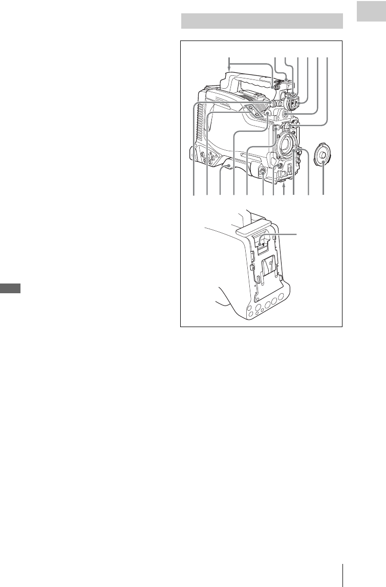
fVF (viewfinder) connector (20-pin)
Connect an optional viewfinder.
Consult a Sony representative for information about
available viewfinders.
gLens mount securing rubber
After locking the lens in position using the lens
locking lever, fit this rubber over the lower of the
two projections. This fixes the lens mount,
preventing it from coming loose.
hViewfinder front-to-back positioning
knob (LOCK knob)
Loosen this knob to adjust the front-to-back
position of the viewfinder (see page 37).
iFitting for optional microphone holder
Fit an optional CAC-12 Microphone Holder (see
page 45).
jShoulder pad
Raise the shoulder pad fixing lever to adjust the
position in the front-to-rear direction. Adjust the
position for maximum convenience when
operating the unit on your shoulder.
For details of the adjustment, see “Adjusting the
Shoulder Pad Position” on page 51.
kLIGHT (video light) connector (2-pin,
female)
A video light with a maximum power
consumption of 50 W, such as the Anton Bauer
Ultralight 2 or equivalent can be connected (see
page 50).
lLens cable clamp
Clamp a lens cable.
mMIC IN (microphone input) (+48 V)
connector (XLR type, 5-pin, female)
Connect a stereo microphone to this connector.
The power (+48 V) is supplied via this connector.
nLENS connector (12-pin)
Connect a lens cable to this connector.
Note
When connecting the lens cable to this connector,
power off this unit first.
oTripod mount
When using the unit on a tripod, attach the tripod
adaptor (optional).
pLens mount (special bayonet mount)
Attach the lens.
Consult a Sony representative for information about
available lenses.
qLens locking lever
After inserting the lens in the lens mount, rotate
the lens mount ring with this lever to lock the lens
in position.
After locking the lens, be sure to use the lens
mount securing rubber to prevent the lens from
becoming detached.
rLens mount cap
Remove by pushing up the lens locking lever.
When no lens is mounted, keep this cap fitted for
protection from dust.
sCA (camera adapter) connector (50-
pin)
Remove the connector cover, and connect the 50-
pin connector of the HDCA-702 MPEG TS
Adaptor.
Refer to the operation manual of the HDCA-702 for
more information about how to mount it.
Locations and Functions of Parts and Controls 17
Chapter 1 Overview
Front
aREC START (recording start) button
Press to start recording. Press it again to stop
recording. The effect is the same as that of the
REC button on the lens.
bSHUTTER selector
Set to ON to use the electronic shutter. Flick to
SELECT to switch the shutter speed or shutter
mode setting within the range previously set with
the menu. When this switch is operated, the new
setting appears on the setting change/adjustment
progress message display area for about three
seconds.
For details about the shutter speed and shutter mode
settings, see “Setting the Electronic Shutter” on
page 60.
cFILTER selector
Selects from the four neutral density (ND) filters
built into this unit.
When this selector is used with the menu item for
filter selection display set to ON (see page 172),
the new setting appears on the viewfinder screen
for about three seconds.
You can change a MAINTENANCE menu
setting so that different white balance settings can
be stored for different FILTER selector positions.
This allows you to automatically obtain optimum
white balance for the current shooting conditions
in linkage with the filter selection.
For details, see “Adjusting the white balance” on
page 56.
dMENU knob
Changes the page selection or a setting within the
menu.
For details about how to use the MENU knob, see
“Menu Operations” on page 163.
eEARPHONE jack (monaural,
minijack)
You can monitor the E-E 1) sound during
recording and playback sound during playback.
When an alarm is indicated, you can hear the
alarm sound through the earphone. You can use
this with the EARPHONE jack on the rear of the
unit at the same time. Plugging an earphone into
the jack automatically cuts off the built-in
speaker.
1) E-E: Abbreviation of “Electric-to-Electric”. In E-E
mode, video and audio signals input to the camcorder
are output after passing through internal electric
circuits only. This can be used to check input signals.
fAUTO W/B BAL (automatic white/
black balance adjustment) switch
Activates the automatic white/black balance
adjustment functions.
WHT: Adjusts the white balance automatically.
If the WHITE BAL switch (see page 19) is
set to A or B, the white balance setting is
Operating and connectors section
2
1
7
5
6
3
4
Position number ND filter
1 CLEAR
21/4 ND (attenuates light to
approximately 1/4)
31/16 ND (attenuates light to
approximately 1/16)
41/64 ND (attenuates light to
approximately 1/64)
Locations and Functions of Parts and Controls
18
Chapter 1 Overview
stored in the corresponding memory. If the
WHITE BAL switch is set to PRST, the
automatic white balance adjustment function
does not operate.
BLK: Adjusts the black set and black balance
automatically.
gMIC (microphone) LEVEL control
Adjusts the input level of audio channels 1, 2, 3
and 4.
For details, see “Adjusting the Audio Level” on page
65.
Right side (near the front)
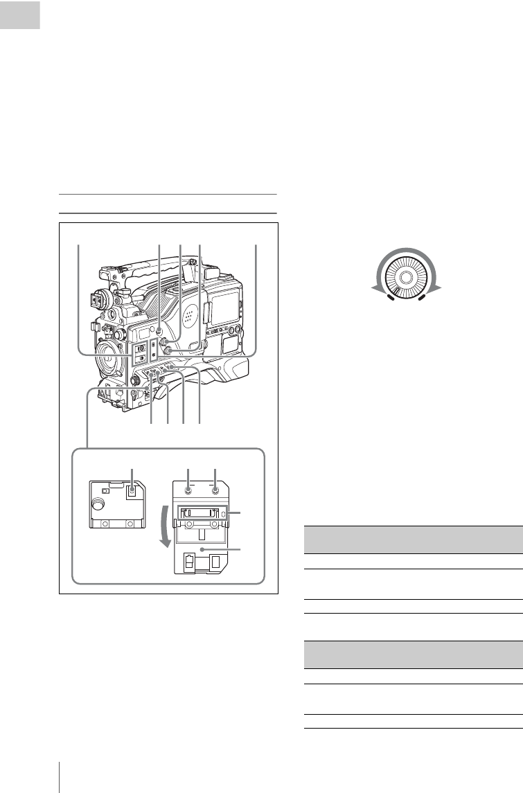
aASSIGN (assignable) 1/2 switches
You can assign the desired functions to these
switches on the ASSIGNABLE SW page of the
OPERATION menu.
Nothing is assigned to these switches when the
camcorder is shipped from the factory (equivalent
to a selection of OFF in the menu).
For details, see “Assigning functions to ASSIGN
switches” on page 178.
bCOLOR TEMP. (color temperature)
button
Press to light the button and change the color
temperature for shooting. You can use this as an
ASSIGN (assignable) switch (see page 178).
cALARM (alarm tone volume
adjustment) knob
Controls the volume of the warning tone that is
output via the built-in speaker or optional
earphones. When the knob is turned to the
minimum position, no sound can be heard.
However, if the MIN ALARM VOL item on the
AUDIO-1 page of the MAINTENANCE menu is
set to SET, the alarm tone is audible even when
this volume control is at the minimum position.
dMONITOR (monitor volume
adjustment) knob
Controls the volume of the sound other than the
warning tone that is output via the built-in speaker
or optional earphones. When the knob is turned to
the minimum position, no sound can be heard.
eMONITOR (audio monitor selection)
switches
By means of combinations of the two switches,
you can select audio that you want to hear through
the built-in speaker or optional earphones.
Position of down-side switch: CH-1/2
Position of down-side switch: CH-3/4
MENU
ON/
SEL
OFF
STATUS
CANCEL/PRST
ESCAPEON
OFF
5
6789
2341
qa qs0
qf
qd
Position of up-side
switch
Audio output
CH-1/CH-3 Channel 1 audio
MIX Channels 1 and 2 mixed
audio (stereo) a)
CH-2/CH-4 Channel 2 audio
Position of up-side
switch
Audio output
CH-1/CH-3 Channel 3 audio
MIX Channels 3 and 4 mixed
audio (stereo) a)
CH-2/CH-4 Channel 4 audio
ALARM
Minimum Maximum

Locations and Functions of Parts and Controls 19
Chapter 1 Overview
a) By connecting stereo headphones to the EARPHONE
jack on the rear of the unit, you can hear the audio in
stereo. (On the AUDIO-1 page of the
MAINTENANCE menu, HEADPHONE OUT must
be set to STEREO.)
fVDR SAVE/STBY (VDR save/standby)
switch
Switches the status of the power supply to the
VDR while recording is stopped (STOP) or
paused (REC PAUSE).
SAVE: The disc stops rotating and some
functions are disabled. Power consumption is
lower than when the camcorder is in STBY
mode. Battery life is extended.
STBY: Recording to the disc starts immediately
when the REC START button is pressed.
Note
An internal operating sound may be recorded at the start
of recording when the VDR SAVE/STBY switch is set to
SAVE.
gGAIN selector
Switches the gain of the video amplifier to match
the lighting conditions during shooting. The gains
corresponding to the L, M, and H settings can be
selected in the menu. (The factory settings are
L=0 dB, M=6 dB, and H=12 dB.)
When this switch is adjusted, the new setting
appears on the setting change/adjustment
progress message display area of the viewfinder
screen for about three seconds.
For details, see “Setting gain values for the GAIN
selector positions” on page 177.
hOUTPUT/DCC (output signal/dynamic
contrast control) switch
Switches the video signal, which is output to the
video disc drive (referred to as “VDR”),
viewfinder, and video monitor from the camera
section, between the following two.
BARS: Outputs the color bar signal.
CAM: Outputs the video signal from the camera.
When this is selected, you can switch DCC 1)
on and off.
1) DCC (Dynamic Contrast Control): Against a very
bright background with the iris opening adjusted to the
subject, objects in the background will be lost in the
glare. The DCC function will suppress the high
intensity and restore much of the lost detail and is
particularly effective in the following cases.
• Shooting people in the shade on a sunny day
• Shooting a subject indoors, against a background
through a window
• Any high contrast scene
iWHITE BAL (white balance memory)
switch
Controls adjustment of the white balance.
PRST: Adjusts the color temperature to the preset
value (the factory default setting: 3200K).
Use this setting when you have no time to
adjust the white balance.
A or B: Recall the white balance adjustment
settings already stored in A or B. Flick the
AUTO W/B BAL switch (see page 17) on the
WHT side, to automatically adjust the white
balance, and save the adjustment settings in
memory A or memory B.
You can use the AUTO W/B BAL switch
even when ATW 1) is in use.
B (ATW): When this switch is set to B and
WHITE SWITCH <B> is set to ATW on the
WHITE SETTING page of the
OPERATION menu, ATW is activated.
When this switch is adjusted, the new setting
appears on the setting change/adjustment
progress message display area of the viewfinder
screen for about three seconds.
1) ATW (Auto Tracing White Balance): The white
balance of the picture being shot is adjusted
automatically for varying lighting conditions.
jSTATUS ON/SEL/OFF (menu display
on/page selection/display off) switch
To enable this switch, set the MENU ON/OFF
switch to OFF.
Closing the cover automatically sets the MENU
ON/OFF switch to OFF.
ON/SEL: Each time this switch is pushed
upward, a window to confirm the menu
settings and status of the camcorder appears
on the viewfinder screen. The window
consists of four pages, which are switched
each time the switch is pushed upward. Each
page is displayed for about 10 seconds.
OFF: To clear the page immediately after
display, push this switch down to the OFF
position.
You can select the pages to be displayed on the
menu.
For details, see “Displaying the status confirmation
screens” on page 176.
Locations and Functions of Parts and Controls
20
Chapter 1 Overview
kMENU ON/OFF switch
To use this switch, open the cover.
This switch is used to display the menu on the
viewfinder screen or the test signal screen.
Closing the cover automatically sets this switch to
OFF.
ON: Displays the menu on the viewfinder screen
or the test signal screen.
OFF: Removes the menu from the viewfinder
screen or the test signal screen.
lCANCEL/PRST (preset)/ESCAPE
switch
To enable this switch, set the MENU ON/OFF
switch to ON.
Closing the cover automatically sets the MENU
ON/OFF switch to OFF.
CANCEL/PRST: Flicking this switch up to this
position displays the message to confirm
whether the previous settings are cancelled or
settings are reset to their initial values,
depending on the menu operating condition.
Flicking this switch up to this position again
cancels the previous settings or resets the
settings to their initial values.
ESCAPE: Use this switch when the menu page,
which has a hierarchical structure, is opened.
Each time the switch is flicked to this
position, the page returns to one stage higher
in the hierarchy.
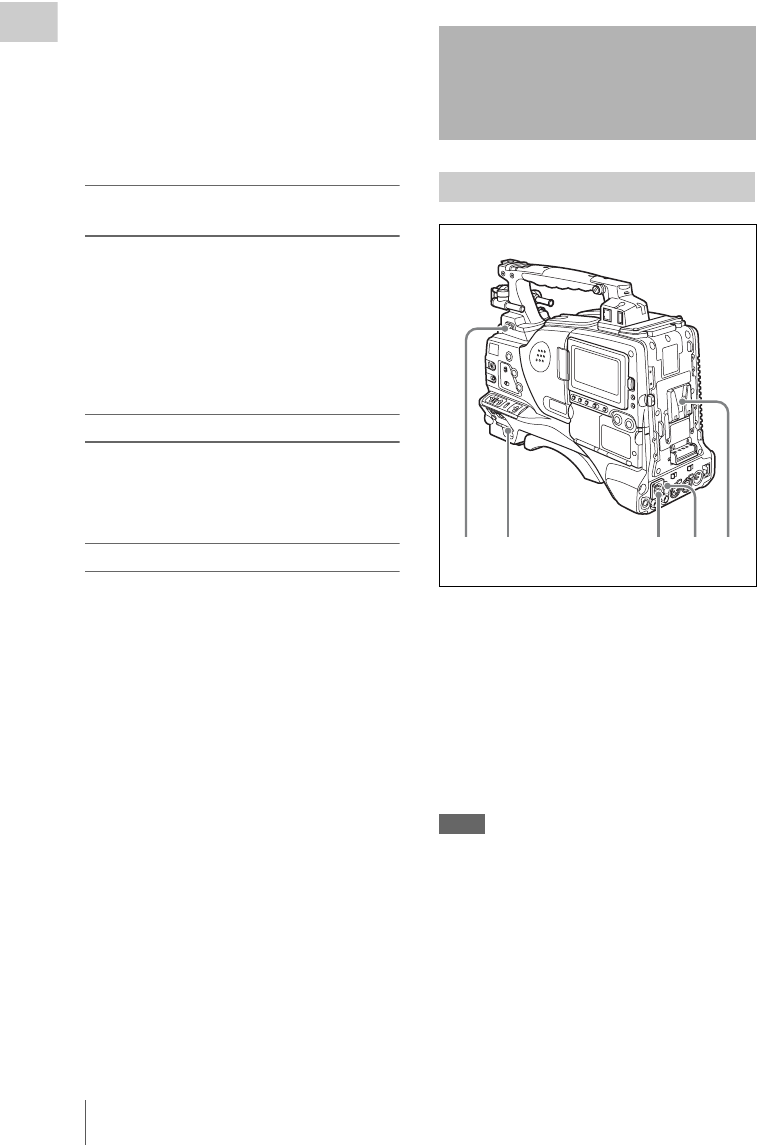
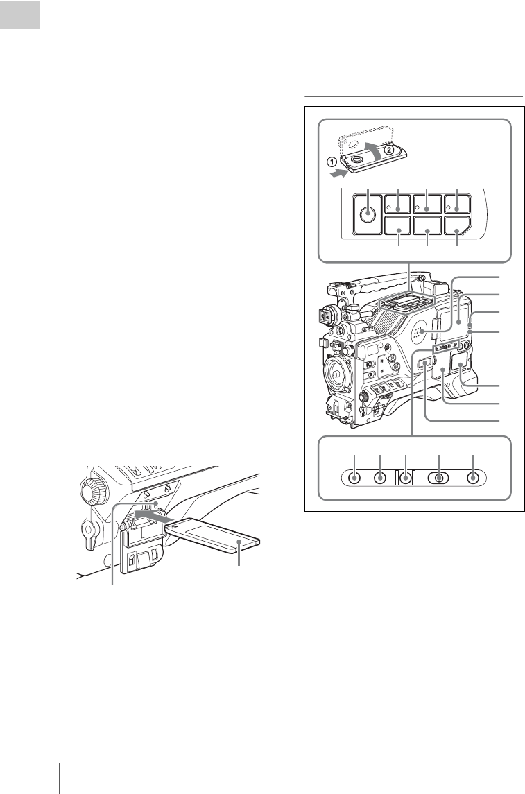
m“Memory Stick” compartment
Open the lid of the menu operating section, and
insert a “Memory Stick”, with the notch facing
downward, in the direction shown by the arrow,
so that it clicks into place.
To remove a “Memory Stick”, first press it in to
release the lock, then withdraw.
The “Memory Stick” access indicator lights in
green when a “Memory Stick” is loaded, and
lights in red when the “Memory Stick” is being
accessed for reading or writing.
For details about “Memory Stick”, see “Handling
the “Memory Stick”” on page 185.
nCover
Right side (near the rear)
aBuilt-in speaker
The speaker can be used to monitor E-E sound
during recording, and playback sound during
playback. The speaker also sounds alarms to
reinforce visual warnings.
If you connect earphones to the EARPHONE
jack, the speaker output is suppressed
automatically.
For details about alarms, see “Operation Warnings”
on page 215.
bLCD monitor
Displays camera video, VDR-related warnings,
remaining battery capacity, remaining disc
capacity, audio levels, time data, and so on.
“Memory Stick” Access indicator
Label
F REV
PREV
Z
PLAY/PAUSE
STOP NEXT
F FWD
m
.
NX
x>
M
EJECT
BRIGHTDISPLAYRESETHOLDDISP SEL
COUNTER TC U-BITEXPAND CHAPTER RETURN
2
3
4
5
6
7
1
qs qd qf
8 9 q; qa
qg qh qj qk ql

Locations and Functions of Parts and Controls 21
Chapter 1 Overview
For details, see “Status Display on the LCD monitor
and monochrome LCD” on page 22.
cWARNING indicator
Lights up or flashes when an abnormality occurs
in the VDR section.
For details about the meaning of the states of the
WARNING indicator, see “Operation Warnings” on
page 215.
dACCESS indicator
This lights when data is written to or read from
the disc.
eProtection cover of the audio control
section
Open to access the audio control section (see page
26).
fProtection cover of the GUI screen
operations section
Open to access the GUI screen operations section
(see page 26).
gMonochrome LCD
This shows the remaining battery capacity,
remaining disc capacity, time data, and so on.
For details, see “Status Display on the LCD monitor
and monochrome LCD” on page 22.
hEJECT button and indicator
Press this button to insert a disc or eject the disc.
The indicator flashes while the disc is being
ejected.
iF REV (fast reverse) button and
indicator
This plays back at high speed in the reverse
direction. The indicator lights during high-speed
playback in the reverse direction.
jPLAY/PAUSE button and indicator
Press this button to view play back video images
using the viewfinder screen or the LCD monitor.
The indicator lights during playback.
Press this button again during playback to pause,
outputting a still image. At this time the indicator
flashes.
This unit is equipped with an image search
function at approximately four times normal
playback speed, for easy checking of recorded
material. To use the image search function at
approximately four times normal playback speed,
press the F REV button or F FWD button during
playback.
At this time the PLAY indicator and F REV or F
FWD indicator light.
kF FWD (fast forward) button and
indicator
This plays back at high speed in the forward
direction. The indicator lights during high-speed
playback in the forward direction.
lPREV button
This jumps to the first frame of the current clip.
During the jump, the F REV indicator flashes.
If you press this together with the F REV button,
the jump is to the first frame of the first recorded
clip on the disc.
mSTOP button
Press this button to stop disc playback.
nNEXT button
This jumps to the first frame of the next clip.
During the jump, the F FWD indicator flashes.
If you press this together with the F FWD button,
the jump is to the last frame of the last recorded
clip on the disc.
oDISP SEL (display selection) /EXPAND
(expand function) button
With each press of this button, the display in the
LCD monitor changes as follows.
If you press this button when the thumbnail
screen is displayed, the duration of the selected
clip is divided into 12, and the first frame of each
of the divisions is shown in a further thumbnail
display (expand function). Each time you press
this button, the division is repeated (to a
maximum of three times, with 1,728 divisions).
Display indication Meaning
Video with
superimposed
information (CHAR)
The LCD monitor displays
the same text information
as the viewfinder.
Video without
superimposed
information (MONI)
The video only appears.
Status display
(STATUS)
Counter indications,
warnings, audio levels, and
similar information appear.
No video image appears.

Locations and Functions of Parts and Controls
22
Chapter 1 Overview
Hold down the SHIFT button and press this
button to step back through the division process.
For details of the expand function, see page 105.
pHOLD (display hold)/CHAPTER
(chapter function) button
Pressing this button instantly freezes the time data
displayed in the counter display section. (The
timecode generator continues running.) Pressing
this button again releases the hold.
You can use this button, for example, to
determine the exact time of a particular shot.
For details of the counter display, see page 23.
If you press this button when the clip thumbnail
screen is displayed, those frames on which shot
marks are recorded appear in a list (chapter
function). Press the button once more to return to
the normal thumbnail display.
By displaying thumbnails with shot marks
attached in place of index frames, you can check
the contents of clips more easily and more
quickly. This is also useful for cueing up long
clips.
For details of the chapter function, see page 106
qRESET/RETURN button
Resets the value shown in the time counter
display. According to the settings of the PRESET/
REGEN/CLOCK switch (see page 26) and the F-
RUN/SET/R-RUN switch (see page 26), this
button resets the display as follows.
a) Of the timecode bits for every frame recorded on the
disc, those bits which can be used to record useful
information for the user such as scene number,
shooting place, etc.
For details, see “Setting the Time Data” on page 68.
This button returns to the previous screen when
pressed during thumbnail display.
For details, see “GUI screen operations” on page
103.
rDISPLAY switch
This cycles the data displayed in the counter
display through the sequence COUNTER, TC,
and U-BIT.
COUNTER: Display the elapsed recording/
playback time (hours, minutes, seconds,
frames).
TC: Display timecode.
U-BIT: Display user bit data.
For details, see “Status Display on the LCD monitor
and monochrome LCD” on page 22.
sBRIGHT (brightness) button
Switches the brightness of the LCD monitor
backlight, and turns the backlight of the
monochrome LCD on and off.
Each press of the button selects the next setting in
the order shown in the following table.
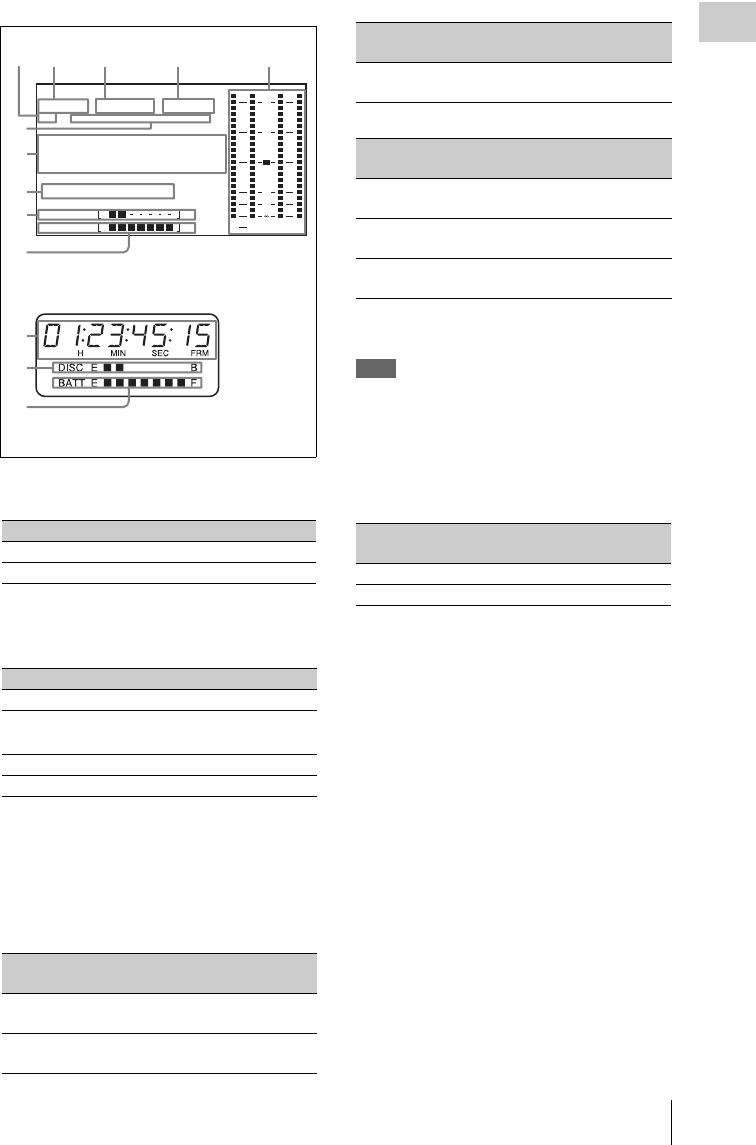
Status Display on the LCD monitor and
monochrome LCD
The following display appears on the LCD
monitor display which is set to STATUS with the
DISP SEL/EXPAND button, and on the
monochrome LCD.
Settings of switches To rese t
DISPLAY switch:
COUNTER
Counter to 0:00:00:00
DISPLAY switch:
TC
PRESET/REGEN/
CLOCK switch:
PRESET
F-RUN/SET/R-RUN
switch: SET
Timecode to 00:00:00:00
DISPLAY switch:
U-BIT
PRESET/REGEN/
CLOCK switch:
PRESET
F-RUN/SET/R-RUN
switch: SET
User bits data a) to 00 00 00
00
Setting LCD monitor
backlight
Monochrome
LCD backlight
H High (select this to view
the LCD monitor
outdoors in the
daytime)
Lit
M Brightness between H
and L
Lit
L Low (select this to view
the LCD monitor
indoors or outdoors at
night)
Lit
OFF Off (the display is also
off)
Off
Locations and Functions of Parts and Controls 23
Chapter 1 Overview
aResolution
Indicates the resolution of HD output video.
bVideo format
Indicates the format of video being currently
played back or recorded.
a) LP is playback only.
cSystem frequency
Indicates the system frequency of video being
currently played back or recorded.
If NTSC AREA is selected 1)
If PAL AREA is selected 1)
1) Selected by COUNTRY setting on the FORMAT page
of the OPERATION menu (see page 135).
Note
There may be no indication displayed when this unit
cannot identify the system frequency, for example, when
playing back a disc recorded with other equipment.
dAudio format
Indicates the format of audio being currently
played back or recorded.
eAudio level indicators
Indicates the audio recording or playback levels
of channels 1 to 4.
fStatus display
PB: Appears during playback.
NDF: Appears when non-drop-frame timecode is
selected.
EXT-LK: Appears when the internal timecode
generator is locked to an external signal input
to the TC IN (timecode input) connector.
HOLD: Appears when the internal timecode
generator is stopped.
gTime counter display
Switches displays of time counter, timecode, and
user bits, depending on the position of the
DISPLAY switch.
When the HOLD/CHAPTER button is pressed to
hold the timecode value, the timecode is
displayed in the format shown below. When the
HOLD/CHAPTER button is pressed again to
Indication Resolution (horizontal × vertical)
1080 1080 lines (1920 × 1080)
720 720 lines (1280 × 720)
Indication Format Bit rate
HD422 50 MPEG HD422 50 Mbps
HD420 HQ/SP/
LP a)
MPEG HD420 35/25/18 Mbps
IMX 50/40/30 MPEG IMX 50/40/30 Mbps
DVCAM DVCAM 25 Mbps
Indication Field or frame
rate
Scan mode
59.9i 59.94 fields per
second
Interlace
59.9P 59.94 frames per
second
Progressive
WARNING:HUMID
HD
422
50
1080
01.
..
..
.
23 45 15
59.9i 24bit
H
PB NDF EXT-LK
21
HOLD
MIN SEC FRM
DISC E B
BATT E F
ST
43
dB
OVER
PEAK
20
10
30
40
0
2134 5
6
7
8
9
0
0
7
9
Monochrome LCD
LCD monitor
29.9P 29.97 frames per
second
Progressive
Indication Field or frame
rate
Scan mode
50i 50 fields per
second
Interlace
50P 50 frames per
second
Progressive
25P 25 frames per
second
Progressive
Indication Quantization bit rate/sampling
frequency
24bit 24 bits/48 kHz
16bit 16 bits/48 kHz
Indication Field or frame
rate
Scan mode

Locations and Functions of Parts and Controls
24
Chapter 1 Overview
release the hold, the timecode is displayed in the
normal format.
hWarning indicator area
Displays warnings when trouble with recording
or moisture condensation occurs.
For details, see “Operation Warnings” on page 215.
Lights when the HOLD/CHAPTER button
is pressed.

Locations and Functions of Parts and Controls 25
Chapter 1 Overview
iRemaining disc capacity indicator
jRemaining battery capacity indicator
a) You can change the threshold voltages on the
BATTERY 2 page of the MAINTENANCE menu
(see page 148).
Indication Remaining recording time
DISC E [x x x x x x x] B More than 30 minutes
DISC E [x x x x x x x] B 25 to 30 minutes
DISC E [x x x x x x x] B 20 to 25 minutes
DISC E [x x x x x x x] B 15 to 20 minutes
DISC E [x x x x x x x] B 10 to 15 minutes
DISC E [x x x x x x x] B 5 to 10 minutes
DISC E [x x x x x x x] B 2 to 5 minutes
DISC E [x x x x x x x] B (flashing) 0 to 2 minutes
DISC E [x x x x x x x] B (flashing) 0 minutes
Indication Battery voltage
BP-L90A/L60S/L80S Other batteries a)
BATT E [x x x x x x x] F 15.5 V or more 17.0 V or more
BATT E [x x x x x x x] F 15.1 to 15.5 V 16.0 to 17.0 V
BATT E [x x x x x x x] F 14.6 to 15.1 V 15.0 to 16.0 V
BATT E [x x x x x x x] F 13.8 to 14.6 V 14.0 to 15.0 V
BATT E [x x x x x x x] F 12.9 to 13.8 V 13.0 to 14.0 V
BATT E [x x x x x x x] F 12.0 to 12.9 V 12.0 to 13.0 V
BATT E [x x x x x x x] F 10.8 to 12.0 V 11.0 to 12.0 V
BATT E [x x x x x x x] F 10.8 V or less 11.0 V or less
Indication Battery voltage
BP-GL95/GL65/IL75/M100, Anton Bauer Battery
System
BATT E [x x x x x x x] F 80 to 100%
BATT E [x x x x x x x] 70%
BATT E [x x x x x x x] 60%
BATT E [x x x x x x x ] 50%
BATT E [x x x x x x x] 40%
BATT E [x x x x x x x] 30%
BATT E [x x x x x x x] 20%
BATT E [x x x x x x x] 10%
BATT E [x x x x x x x]0%

Locations and Functions of Parts and Controls
26
Chapter 1 Overview
GUI screen operations section and audio control
section
aTHUMBNAIL indicator
This lights when thumbnails are displayed.
bTHUMBNAIL/ESSENCE MARK
button
Press this button to carry out a thumbnail search
or create a clip list (see page 105).
When pressed, the whole-screen display changes
to a thumbnail display. Press once more to return
to the whole-screen display.
For a thumbnail search using essence marks, hold
down the SHIFT button and press this button (see
page 106).
cSET/S.SEL (set/scene selection) button
and arrow buttons
Use these buttons to make timecode and user bit
settings, and for GUI screen operations.
The arrow buttons select items and change values,
and the SET/S.SEL button confirms settings.
Pressing this button with thumbnails displayed
and the SHIFT button held down adds a sub clip
to the current clip list (scene selection).
See page 103 for more information about GUI screen
operations.
See page 113 for more information about scene
selection.
dMENU button
Displays a special menu for operations in GUI
screens (see page 100).
When the whole-screen is displayed, pressing this
button has no effect, and the operation is invalid.
eF-RUN/SET/R-RUN (free run/set/
recording run) switch
Selects the operating mode of the internal
timecode generator. The operating mode is set as
explained below, depending on the position of the
switch.
F-RUN: Timecode keeps advancing, regardless
of the operating state of the VDR. Use this
setting when synchronizing the timecode
with an external timecode.
SET: Sets the timecode or user bits.
R-RUN: Timecode advances only during
recording. Use this setting to have a
consecutive timecode on the disc.
For details, see “Setting the timecode” on page 68
and “Setting the user bits” on page 68.
fAUDIO LEVEL CH-1/CH-2 (audio
channel 1/2 recording level) knobs
Adjusts the audio levels to be recorded on
channels 1 and 2 when the AUDIO SELECT CH-
1/CH-2 switches are set to MANUAL.
gSUB CLIP indicator
This lights when using a clip list for playback.
hSUB CLIP/DISC MENU button
Press this to play back according to a clip list.
You can play back a particular clip or sequential
clips, or carry out a search of the selected clip list.
To display the Disc Menu which allows you to
carry out operations such as saving, recalling, or
deleting a clip list, hold down the SHIFT button
and press this button.
iSHIFT button
Use this in combination with other buttons.
jPRESET/REGEN (regeneration)/
CLOCK switch
Selects whether to set a new timecode or to utilize
the existing timecode.
PRESET: Records a new timecode.
REGEN: Records timecode continuous with the
existing timecode recorded on the disc.
Regardless of the setting of the F-RUN/SET/
R-RUN switch, the camcorder operates in R-
RUN mode.
CLOCK: Records timecode synchronized to the
internal clock. Regardless of the setting of
the F-RUN/SET/R-RUN switch, the
camcorder operates in F-RUN mode.
AUTO
FRONT
WIRELESS
THUMBNAIL
SET
S.SEL
SHIFT
ESSENCE
MARK
SUB CLIP
REAR
CH-1
MANUAL
AUDIO SELECT
AUDIO IN
F
W
R
F
W
R
LEVEL
010010
CH-2
CH-3
CH-4
PRESET
F-RUN
REGEN
SET
CLOCK
R-RUN
MENU
DISC MENU
12345 6
7 8 9 0 qa qs

Locations and Functions of Parts and Controls 27
Chapter 1 Overview
kAUDIO SELECT CH-1/CH-2 (audio
channel 1/2 adjustment method
selection) switches
Select the audio level adjustment method for each
of audio channels 1 and 2.
AUTO: Automatic adjustment
MANUAL: Manual adjustment
lAUDIO IN CH-1/CH-2/CH-3/CH-4
(audio channel 1/2/3/4 input selection)
switches
AUDIO IN CH-1/CH-2 switches
Select the audio input signals to be recorded on
audio channels 1 and 2.
FRONT: Audio input signals from the
microphone connected to the MIC IN
connector
REAR: Audio input signals from an audio device
connected to the AUDIO IN CH-1/CH-2
connectors
WIRELESS: Audio input signals from the UHF
portable tuner (not supplied) if it is installed
AUDIO IN CH-3/CH-4 switches
Select the audio input signals to be recorded on
audio channels 3 and 4.
F (FRONT): Audio input signals from a
microphone connected to the MIC IN
connector
R (REAR): Audio input signals from an audio
device connected to the AUDIO IN CH-1/
CH-2 connectors
W (WIRELESS): Audio input signals from the
UHF portable tuner (not supplied) if it is
installed
Left side and upper section
aASSIGNABLE 3/4 switches
You can assign the desired functions to these
switches on the ASSIGNABLE page of the
OPERATION menu.
Nothing is assigned to these switches when the
camcorder is shipped from the factory (equivalent
to a selection of OFF in the menu).
For details, see “Assigning functions to ASSIGN
switches” on page 178.
bLid of the disc compartment
This opens when the EJECT button on the top
panel is pressed. Press the side of the lid to close.
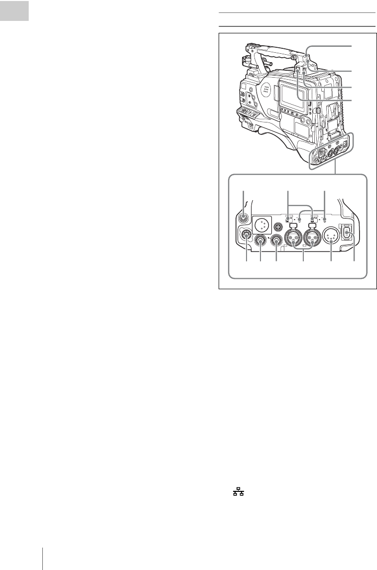
cSDI IN (OPTION) connector (BNC
type)
This is an input connector for the optional CBK-
HD01 HD/SD SDI Input Board. When the CBK-
HD01 is installed, the unit can record HD-SDI or
SD-SDI signals that are input to this connector.
dGENLOCK IN (genlock signal input)
connector (BNC type)
• This connector inputs a reference signal when
the camera is to be genlocked or when timecode
is to be synchronized with external equipment.
GENLOCK
IN
TC
OUT
TEST
OUT
TC IN
SDI IN
(OPTION)
1
2
345
67
Locations and Functions of Parts and Controls
28
Chapter 1 Overview
Use the GENLOCK page of the
MAINTENANCE menu to adjust the genlock
H-phase (phase of horizontal sync signal).
• This connector also inputs a return video signal.
You can display the HD-Y (1080i) signal in the
viewfinder screen while holding the RET button
down with RETURN VIDEO set to ON on the
ASSIGNABLE SW page of the OPERATION
menu.
• Input an external video signal. When the
optional CBK-SC02 Analog Composite Input
Board is installed, the unit can record analog
composite video signals that are input to this
connector.
eTC IN (timecode input) connector
(BNC type)
To apply an external lock to the timecode of this
unit, input the reference timecode.
For details of timecode, see “Setting the timecode”
on page 68.
fTEST OUT connector (BNC type)
This connector outputs the video signal for a
video monitor. The output signal can be selected
from composite video, HD-Y, R, G, B, and a
composite video signal like that displayed in the
LCD monitor. To switch output signals, use the
TEST OUT SELECT item on the OUTPUT 1
page of the OPERATION menu.
If the output signal is set to one of R, G, or B, then
this setting changes to HD-Y when the camcorder
is powered off and on again.
Depending on menu settings, menus, timecode,
and shot data can be superimposed on the image
on the monitor. This connector can also be used to
synchronize the timecode of an external VTR
with the timecode of the camcorder.
gTC OUT (timecode output) connector
(BNC type)
To lock the timecode of an external VTR to the
timecode of this unit, connect this connector to
the external VTR’s timecode input connector.
Rear
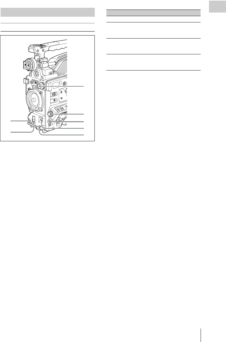
aTALLY (back tally) indicator (red)
Lights up during recording. It will not light if the
TALLY switch is set to OFF. This indicator also
flashes to indicate warnings (see page 21) in the
same manner as the REC/TALLY indicator in the
viewfinder.
For details, see “Operation Warnings” on page 215.
bTALLY switch
Set to ON to activate the TALLY indicator
function.
cUSB connector
This is a USB 2.0 connector.
Connect a Windows USB keyboard or mouse (see
page 110), or a USB flash drive to access
planning metadata stored on the drive (see page
121).
d (network) connector (RJ-45 type)
This is a 10BASE-T/100BASE-TX connector for
network connection.
SDI OUT
DC OUT
12V
0.5A
LINE
SUPER
MIC
48V
OFF
CH1
1/2
SDI OUT
DC
IN
AES/EBU AUDIO IN
AUDIO OUT
CH2
3/4
LINE MIC
48V
OFF
AES/EBU
89 0 qa qs qd
1
2
3
4
567

Locations and Functions of Parts and Controls 29
Chapter 1 Overview
CAUTION
When you connect the network cable of the unit to
peripheral device, use a shielded-type cable to prevent
malfunction due to radiation noise.
eEARPHONE jack (stereo, minijack)
You can monitor the E-E sound during recording
and playback sound during playback. When an
alarm is indicated, you can hear the alarm sound
through the earphone. You can use this with the
EARPHONE jack on the front of the unit at the
same time. Plugging an earphone into the jack
automatically cuts off the built-in speaker.
You can select monaural or stereo on the AUDIO-
1 page of the MAINTENANCE menu.
fLINE /AES/EBU / MIC selectors
These select the audio source of the audio input
signals input to the AUDIO IN CH1/CH2
connectors.
LINE: Line input audio equipment
AES/EBU: AES/EBU format audio signal
MIC: Microphone input
Note
When these switches are in the MIC position, and the
+48V/OFF switch is set to +48V, if you inadvertently
connect any audio device other than a microphone to the
AUDIO IN CH1/CH2 connectors, the device may be
damaged.
g+48V/OFF switches
Select either of the following positions for the
microphones to be connected.
+48V: For a microphone to use an external power
supply
OFF: For a microphone to use an internal power
supply
hREMOTE connector (8-pin)
Connect an RM-B150/B750 Remote Control
Unit, which makes it possible to control the
camcorder remotely.
Note
Before connecting/disconnecting the Remote Control
Unit to/from the camcorder, be sure to turn off the
camcorder POWER switch.
iSDI OUT 1 connector (BNC type)
Outputs an HDSDI or SDSDI signal (with
embedded audio). To switch between HDSDI and
SDSDI output, use the SDI OUT 1 SELECT item
on the OUTPUT 1 page of the OPERATION
menu.
jSDI OUT 2 connector (BNC type)
Outputs an HDSDI or SDSDI signal (with
embedded audio). To switch between HDSDI and
SDSDI output, use the SDI OUT 2 SELECT item
on the OUTPUT 1 page of the OPERATION
menu.
Setting menus, timecode, or shot data can be
superimposed on the camera output video
depending on the menu settings, and you can
view them on the monitor screen.
kAUDIO IN CH1/CH2 (audio channel-1
and channel-2 input) connectors (XLR
type, 3-pin, female)
These are audio input connectors for channels 1
and 2 to which you can connect audio equipment
or a microphone.
When the LINE / AES/EBU / MIC selector is set
to AES/EBU, the CH1 connector is used for
channel-1 and -2 inputs, and the CH2 connector,
for channel-3 and -4 inputs.
lAUDIO OUT connector (XLR type, 5-
pin, male)
Outputs the audio signals recorded on audio
channels 1 and 2 or audio channels 3 and 4. The
audio signals are selected by the MONITOR
switch.
m (i.LINK) S400 connector (6-pin,
IEEE1394 compliant)
Use an i.LINK cable (DV cable) to connect the
camcorder to a computer for File Access Mode
file operations.
For details, see “File Operations in File Access
Mode (for Windows)” on page 199).
Note
When you connect the camcorder and other equipment,
such as a hard disk drive, with an i.LINK interface to a
computer with i.LINK connectors, turn off the power of
the computer, the other equipment, and the camcorder
before connecting them using the i.LINK cable (DV
cable). If a bus-powered type 1) hard disk drive or similar
equipment is connected while the computer is powered
on, electric current flows into the camcorder because of
the high voltage caused by the load shift of the computer
power, and this may cause a malfunction.
1) Equipment that can be powered through i.LINK cable
(DV cable)
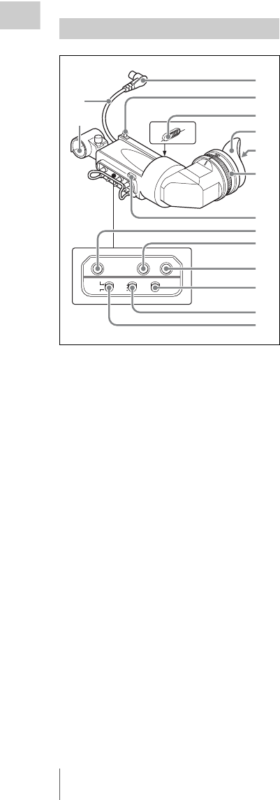
Locations and Functions of Parts and Controls
30
Chapter 1 Overview
aPlug
Connect to the VF connector on the camcorder.
bStopper
Prevents the viewfinder from coming off the
camcorder when it is slid from side to side.
cCamera operator tally indicator
Lights up while camcorder is recording. This
indicator can be covered when not in use.
This indicator also flashes to indicate warnings, in
the same manner as the tally indicator and the
REC indicator in the viewfinder.
dEyecup
eIndicators and status display
For details, see “Status display on the viewfinder
screen” on page 31.
fDiopter adjustment ring
Allows for optimal focus adjustment.
gTally indicator
Lights up while camcorder is recording. Set the
TALLY switch to OFF when not in use. The
brightness can also be adjusted with the TALLY
switch.
This indicator also flashes to indicate warnings, in
the same manner as the camera operator tally
indicator and the REC indicator in the viewfinder.
hPEAKING control
Turning this control clockwise adjusts the picture
sharpness, and makes focusing easier. This
control has no effect on the output signals of the
camcorder.
iCONTRAST control
Adjusts the contrast of the screen. This control
has no effect on the output signals of the
camcorder.
jBRIGHT control
Adjusts the brightness of the screen. This control
has no effect on the output signals of the
camcorder.
kTALLY switch
Controls the tally indicator located on the front of
the viewfinder.
HIGH: The tally indicator brightness is set to
high.
OFF: The tally indicator is disabled.
LOW: The tally indicator brightness is set to low.
lZEBRA (zebra pattern) switch
Controls the zebra pattern display on the
viewfinder screen as follows.
ON: A zebra pattern appears and stays.
OFF: The zebra pattern disappears.
MOMENT: A zebra pattern appears and stays for
about five seconds.
mDISPLAY/ASPECT switch
Turns the marker indication on and off, and
switches between 4:3 and 16:9 aspect ratios for
viewfinder screen display.
DISPLAY: When the marker indication is
enabled with the camcorder, the marker
indication on the viewfinder screen turns on
and off every time you push the switch up to
this position.
ASPECT: Each push of the switch down to this
position toggles the mask display on and off.
(Make mask display settings on the
MARKER 1 page of the OPERATION menu
(see page 132).)
HDVF-20A viewfinder (optional)
PEAKING CONTRAST BRIGHT
DISPLAY
ASPECT
TALLY
HIGH
LOW
OFF
ZEBRA
ON
MOMENT
OFF
0
qa
qs
q
d
1
2
3
4
5
6
7
8
9
qf
qg
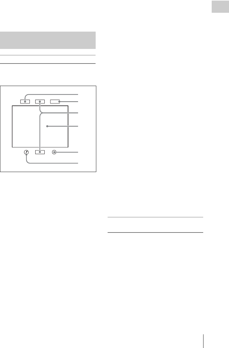
Locations and Functions of Parts and Controls 31
Chapter 1 Overview
nViewfinder cable
oMicrophone holder
Indicators
The following indicators are arranged above and
below the viewfinder screen to show the current
state and adjustments of the camcorder.
aTALLY (green tally) indicator
Lights when the camcorder is the following
states.
• Picture Cache mode enabled
• Disc Exchange Cache mode enabled
• Recording with HDSDI REMOTE I/F on the
CAM CONFIG 1 page of the MAINTENANCE
menu set to G-TLY
Flashes when the camcorder is the following
states.
• Set to Auto Interval Rec mode or the
consecutive mode of Manual Interval Rec mode
(1 flash per second)
• Recording in Auto Interval Rec mode or
recording in the consecutive mode of Manual
Interval Rec mode (4 flashes per second)
• Set to the single-shot mode of Manual Interval
Rec mode, or recording in that mode (2 flashes
per second)
bBATT (battery) indicator
This indicator starts flashing when the battery
connected to the camcorder is nearly exhausted,
and stays lit when the battery is completely
exhausted.
To prevent interruption during operation, replace
the battery as soon as this indicator starts flashing.
The battery power level at which the indicator starts
flashing can be set on the BATTERY 1 page of the
MAINTENANCE menu. For details, see page 147.
cREC (recording, red tally) indicator
Lights up while camcorder is recording.
This indicator also flashes to indicate warnings, in
the same manner as the tally indicator and the
camera operator tally indicator.
dViewfinder screen
eVTR SAVE indicator
This indicator lights when the VDR SAVE/STBY
switch is set to SAVE, putting the VDR into
power save mode.
f! (warning) indicator
This indicator lights when any of the following
conditions occurs with the corresponding item set
to ON on the ‘!’ LED page of the OPERATION
menu.
• The gain is set to other than 0 dB.
• The SHUTTER selector is set to ON.
• The WHITE BAL switch is set to PRST.
• ATW is enabled.
• The lens extender is used.
• The FILTER selector is set to other than ND:1.
• The reference value of auto iris adjustment is
not the standard value.
Layout of the status display on the
viewfinder screen
The viewfinder screen displays not only the video
picture but also characters and messages
indicating the camcorder settings and operating
status, a center marker, a safety zone marker, etc.
When the menu screen is not displayed and the
DISPLAY of the DISPLAY/ASPECT switch is
set to ON, the items for which an ON setting was
made on the VF DISP 1, VF DISP 2, or VF DISP
3 page of the OPERATION menu or with related
switches are displayed at the top and bottom of
the screen.
The messages that give details of the settings and
adjustment progress and results can also be made
to appear for about three seconds while settings
Status display on the viewfinder
screen
TALLY/REC
BATT
VTR
SAVE
1
2
4
5
6
3

Locations and Functions of Parts and Controls
32
Chapter 1 Overview
are being changed, during adjustment, and after
adjustment.
For details about the display item selection, see
“Selecting the display items” on page 171.
For details about setting change and adjustment
progress messages, see “Change confirmation/
adjustment progress messages” on page 172.
For details about marker display, see “Setting the
marker display” on page 173.
All items that can be displayed on the viewfinder
screen are shown below.
aColor temperature
Displays a color temperature calculated from the
gain of R and B, in the range 0.0 K to 99.9 K (in
steps of 0.1 K). The +/– signs may be displayed
depending on the OFFSET WHT setting (see
page 182).
No display: OFFSET WHT is OFF
+: The value of OFFSET WHT is greater than
3200K.
–: The value of OFFSET WHT is less than
3200K.
bVideo format
Indicates the format of video being currently
played back or recorded (see page 54).
The video aspect ratio (16:9 or 4:3) can also be
displayed when the recording format is set to
IMX 50, IMX 40, IMX 30, or DVCAM.
cExtender
Displays the extender settings of this unit and the
lens.
EX: The lens extender is on.
08: The lens shrinker is on.
x2D: This unit’s extender function is on.
Ex2D: The lens extender and the digital extender
function of this unit are both on.
dZoom position
Indicates the zoom position of the zoom lens in
the range from 0 to 99.
eClip information
Displays clip information during playback.
During clip playback and search (when title
display is off): Displays the clip number and
total number of clips.
During clip playback and search (when title
display is on): Displays the title specified in
planning metadata as the clip name,
according to the setting of Planning Clip
Name in Clip Info. Area in the Disc Menu
(see page 123).
During clip list playback: Displays the name of
the clip list, the sub clip number, and the total
number of sub clips.
fWireless microphone reception level
When a UHF portable tuner is installed in the
camcorder, “W” appears together with four-
segment reception level indicators for each of the
channels (1 or 2 channels) that can be used by the
tuner. The indications are as follows.
Normal use: The number of white segments
indicates the strength of the signal level.
Muted: The number of gray segments indicates
the strength of the signal level.
Reception level over peak: “P” is displayed
instead of the indicators. 1)
Tuner battery is low: The channel number and
indicator of the corresponding channel
flash. 1)
1) DWR-S01D only
gPower source voltage/battery
remaining capacity
When the unit is powered from a battery pack,
indicates the remaining capacity of the power
source voltage. When the unit is powered from a
battery connected to the DC IN connector or AC
adaptor attached to the battery attachment shoe,
indicates the power source voltage.
hExternal battery
Appears if the power is supplied from an AC
adaptor connected to the DC IN connector.
123 4 5 6 7 8
90q
a
q
s
q
d
q
f
q
g
q
h
q
j
w
;
q
l
q
k
w
s
w
a
EX Z W
13.4
V
99 1 2
HD422 50 E0001:004/004 DC IN
13.9
K+
WHITE:NG
LEVEL TOO HIGH EXT
REC2 TCG 01:23:45:15 HDSDI
1 -
125
C
LOW LIGHT
5600
F1.718 35 30dB 1/ 2000
1
2
W:A

Locations and Functions of Parts and Controls 33
Chapter 1 Overview
iControlling external device
Appears when HDSDI REMOTE I/F in the CAM
CONFIG 1 page of the MAINTENANCE menu
is set to CHARA, and this unit is controlling
recoding by an external device connected to the
SDI OUT 1/2 connectors (HDSDI output). 1)
1) SDI OUT 1 SELECT or SDI OUT 2 SELECT on the
OUTPUT 1 page of the OPERATION menu must be
set to HDSDI.
jElectric color temperature filter
Appears when the CC 5600K function is set to
ON.
kFilter
Indicates the currently selected filter type (see
page 17).
When the function that switches between
electrical CC filters has been assigned to an
ASSIGN switch (see page 59), and when a
remote control unit has been connected, the
electrical CC filter position (A, B, C, or D)
appears to the right side of the ND filter display
(1 to 4).
lWhite balance memory
Indicates the currently selected white balance
automatic adjustment memory.
A: Displayed when the WHITE BAL switch is set
to A.
B: Displayed when the WHITE BAL switch is set
to B.
P: Displayed when the WHITE BAL switch is set
to PRST or when the preset button on an RM-
B150 has been pushed.
T: Displayed when ATW is being used.
3200: Displayed when the COLOR TEMP SW
3200K function is set to ON.
4300: Displayed when the COLOR TEMP SW
4300K function is set to ON.
5600: Displayed when the COLOR TEMP SW
5600K function is set to ON.
6300: Displayed when the COLOR TEMP SW
6300K function is set to ON.
mTimecode
Indicates the elapsed recording/playback time,
timecode, user bits or other information selected
by the DISPLAY switch (see page 22).
nGain value
Indicates the gain value (in dB) of the video
amplifier, as set by the GAIN selector.
oShutter speed
Indicates the shutter speed or the shutter mode.
However, if the SHUTTER selector (see page 17)
is set to OFF, nothing is displayed.
For details of the displayed shutter speed, see
“Setting the Electronic Shutter” on page 60.
pOperation/alarm message display area
For details, see “Operation/alarm messages” on
page 218.
qAudio level
Indicates the level of audio channel 1 and channel
2. The peak indication of the VDR level meter is
related as follows to the audio level.
The segment colors change from gray to white at
or above the AU REF LEVEL set on the AUDIO-
2 page of the MAINTENANCE menu. This
setting does not affect the relationship between
the number of lit segments and the audio levels.
The example in the above figure shows the colors
when AU REF LEVEL is set to –20 dB.
rRemaining disc capacity
Indicates the remaining recording time (in
minutes) of the disc.
-52 -28 -20 -12 -8 (dB)
1
2
3
1Audio channel 1 level indicator
2Audio channel 2 level indicator
3VDR level meter indicator

Locations and Functions of Parts and Controls
34
Chapter 1 Overview
Examples of remaining recording time indication
sRemaining clips display
Displays the remaining number of clips that can
be recorded. The display flashes once per second
when the number of remaining clips is less than
10.
tIris setting/auto iris override
Indicates the F value (iris setting) of the lens.
Auto iris override is shown by an indicator made
up of two segments each on the upper and lower
sides.
For details, see “Changing the Reference Value for
Automatic Iris Adjustment” on page 63.
uExternal input status
When the REC VIDEO SOURCE item on the
SOURCE SEL page of the OPERATION menu
has been set to EXT, then “EXT” and the signal
type (HDSDI, SDSDI, or VBS) flashes when a
valid signal is input to this unit.
For details, see “Recording video from external
devices” on page 93.
vSetting change and adjustment
progress message display area
For details, see “Change confirmation/adjustment
progress messages” on page 172.
Indication Remaining recording
time
.
.
.
.
.
.
110 < 120 to 110 minutes
100 < 110 to 100 minutes
90 < 100 to 90 minutes
90 - 85 90 to 85 minutes
85 - 80 85 to 80 minutes
.
.
.
.
.
.
20 - 15 20 to 15 minutes
15 - 10 15 to 10 minutes
10 - 5 10 to 5 minutes
5MIN (flash) 5 minutes
4MIN (flash) 4 minutes
3MIN (flash) 3 minutes
2MIN (flash) 2 minutes
1MIN (flash) 1 minutes
0MIN (flash) 0 minutes
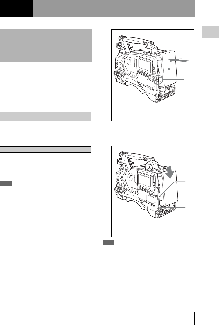
Preparing a Power Supply 35
Chapter 2 Preparations
For safety, use only the Sony battery packs and
AC adaptors listed below.
• BP-GL95/GL65/L60S/L80S Lithium-ion
Battery Pack
• AC power using the AC-DN2B/DN10 AC
adaptor
When a BP-GL95/GL65/L60S/L80S Battery
Pack is used, the camcorder will operate
continuously for the time shown below.
Note
The battery pack operating time depends on the
frequency of use of the battery pack, and the ambient
temperature when used.
Before use, charge the battery pack with a charger
suitable for each battery.
For details on the battery charging procedure, refer
to the battery charger operation manual.
Note on using the battery pack
A warm battery pack may not be able to be fully
recharged.
To attach the battery pack
1Press the battery pack against the back
of the camcorder, aligning the line on
the side of the battery pack with the
matching line on the camcorder.
2Slide the battery pack down until its
“LOCK” arrow points at the matching
line on the camcorder.
Note
If the battery pack is not attached correctly, the terminal
may be damaged.
To detach the battery pack
Holding the release button in, pull the battery
pack up.
Chapter2Preparations
Preparing a Power
Supply
Using a battery pack
Model name Operating time
BP-GL95 Approx. 120 minutes
BP-GL65 Approx. 75 minutes
BP-L60S Approx. 75 minutes
BP-L80S Approx. 100 minutes
1
2
1BP-GL95/GL65/L60S/L80S
2Align these lines.
1
2
1“LOCK” arrow
2Matching line on the camcorder
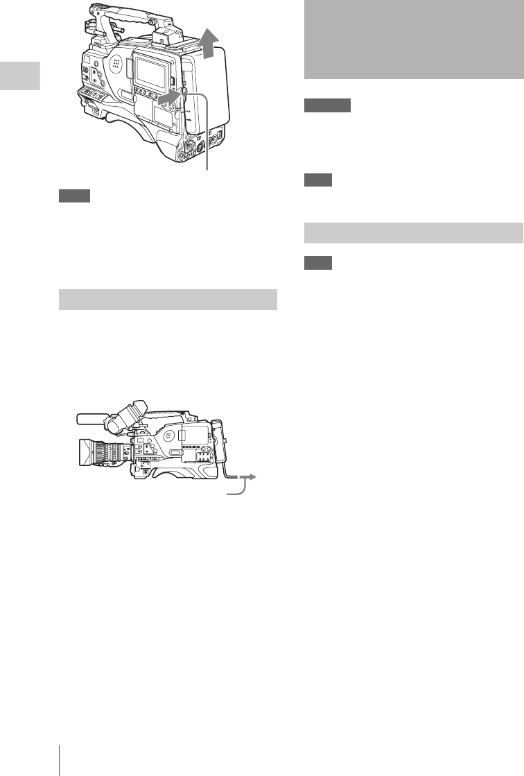
Attaching the Viewfinder
36
Chapter 2 Preparations
Notes
• During recording and playback (while the ACCESS
indicator is lit), be careful never to remove the battery
pack.
• Make sure to power the camcorder off before replacing
the battery pack.
When using the AC-DN10 AC adaptor
Mount an AC-DN10 on the camcorder in the
same way as a battery pack, then connect to the
AC power supply.
The AC-DN10 can supply up to 100 W of power.
CAUTION
When the viewfinder is attached, do not leave the
camcorder with the eyepiece facing the sun. Direct
sunlight can enter through the eyepiece, be focused in the
viewfinder and cause fire.
Note
The viewfinder is supplied separately.
Note
When attaching the viewfinder, make notes of the
following points.
• Be sure to the power off the camcorder before coupling
the viewfinder connector to the camcorder’s VF
connector. If you make this connection when the
camcorder power is on, the viewfinder may not
function properly.
• Couple the viewfinder connector firmly to the
camcorder’s VF connector. If the coupling is loose,
noise may appear on the video or the tally light may not
operate properly.
For more information about the connection of the
viewfinder and camcorder, contact a Sony service
representative.
11 Loosen the viewfinder left-to-right
positioning ring, 2 attach the
viewfinder to the viewfinder fitting
shoe, and 3 tighten the viewfinder left-
to-right positioning ring.
Using AC power
Release button
To an AC outlet
Attaching the Viewfinder
Attaching the HDVF-20A/C35W
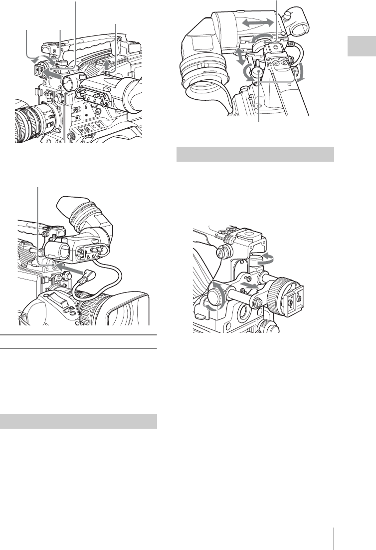
Attaching the Viewfinder 37
Chapter 2 Preparations
2Couple the viewfinder connector to the
VF connector.
Detaching the viewfinder
You can carry out this by following the attaching
procedure in reverse order, but there is an
additional action to take: when detaching the
viewfinder from the fitting shoe, pull up the
stopper.
To adjust the viewfinder left-right position,
loosen the left-right positioning ring, and to adjust
the front-back position, loosen the front-to-back
positioning knob.
1Loosen the front-to-back viewfinder
positioning levers and the front-to-back
viewfinder positioning knobs, and then
pull the viewfinder slide assembly
forward.
2Using a 2.5 mm diameter hexagonal
wrench, detach the viewfinder slide
assembly and handle front cover.
Adjusting the viewfinder position
2
31
Stopper
Viewfinder left-to-right positioning ring
VF connector
Moving the viewfinder shoe up
Viewfinder front-to-back positioning knob
Viewfinder left-to-right positioning ring
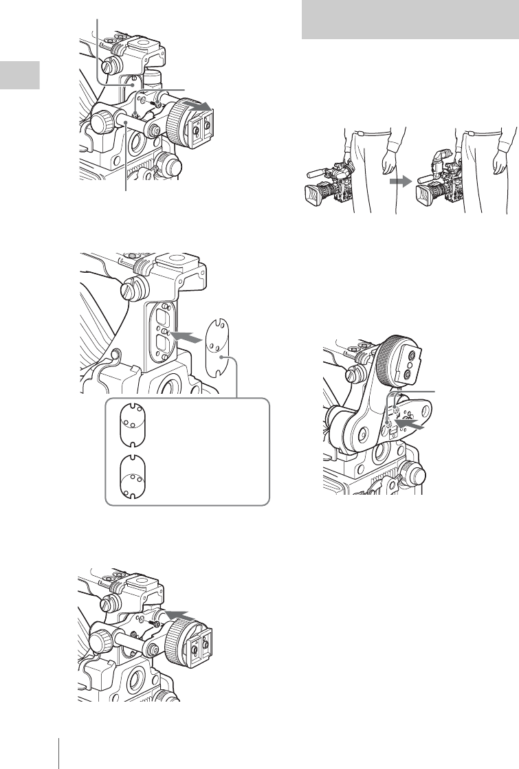
Attaching the Viewfinder
38
Chapter 2 Preparations
3Attach the handle front cover with the
bottom edge up.
4Attach the viewfinder slide assembly,
reversing the steps of the removal
procedure.
By fitting a BKW-401 Viewfinder Rotation
Bracket (not supplied), you can rotate the
viewfinder out of the way so that your right leg
does not hit the viewfinder while you are carrying
the camcorder.
1Carry out steps 1 and 2 of the previous
section “Moving the viewfinder shoe
up” to detach the viewfinder slide
assembly.
2Attach the BKW-401 with the supplied
bolts.
3Adjust the front-to-back position so
that the arm of the BKW-401 does not
touch the handle when it is raised.
Handle front cover
Bolt with
hexagonal hole
Viewfinder slide assembly
To attach the viewfinder
at the top
To attach the viewfinder
at the bottom (factory
default)
Using the BKW-401 Viewfinder
Rotation Bracket
Bolts supplied
with the BKW-401
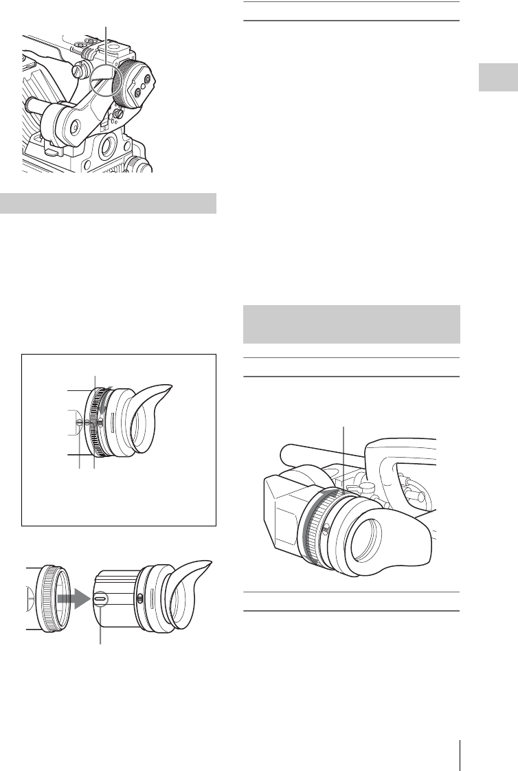
Attaching the Viewfinder 39
Chapter 2 Preparations
Removing the eyepiece gives a clearer view of the
screen from further away. It is also easy to
remove dust from the viewfinder screen and
mirror when the eyepiece is detached.
1Turn the eyepiece locking ring fully
counterclockwise, to align the red
marks on the locking ring and the
viewfinder barrel.
2Detach the eyepiece.
To reattaching the eyepiece
1Align the red marks on the eyepiece
locking ring and the viewfinder barrel.
2Align the red mark on the end of the
eyepiece end with the red marks on the
eyepiece locking ring and the
viewfinder barrel. Then insert the
eyepiece into the viewfinder barrel.
3Turn the eyepiece locking ring
clockwise until its “LOCK” arrow
points at the red mark on the viewfinder
barrel.
When the eyecup is worn out, replace it with a
new one.
For details of a replacement eyecup, contact a Sony
service representative.
To adjust the viewfinder focus
Turn the diopter adjustment ring until the
viewfinder image is sharpest.
To adjust the viewfinder screen
Adjust the brightness, contrast, and peaking of the
viewfinder screen with the controls shown below.
Detaching the eyepiece
Adjust position so that arm
does not touch handle
1
23
1Locking ring
2Locking ring match mark
3Match mark on the viewfinder barrel
Match mark on end of eyepiece
Adjusting the viewfinder focus
and screen
Diopter adjustment ring
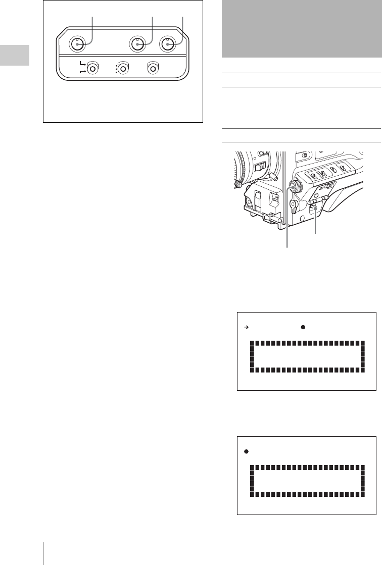
Setting the Area of Use
40
Chapter 2 Preparations
When using the unit for the first time
The area of use is not factory preset. Before using
this unit, you need to set this item. (You cannot
use the unit without setting this item.)
To set the area of use
1Set the POWER switch to the ON
position.
The screen for setting the area of use appears
in the viewfinder.
2Press the MENU knob.
z on the left of NOT SELECTED changes to
?, and you can now select the area of use.
1 2 3
PEAKING CONTRAST BRIGHT
TALLY
HIGH
LOW
OFF
ZEBRA
ON
MOMENT
OFF
DISPLAY
ASPECT
1PEAKING control
2CONTRAST control
3BRIGHT control
Setting the Area of Use
MENU knob
POWER switch
COUNTRY : NOT SELECTED
SYSTEM LINE : 1080
SET FORMAT
AND TURN OFF ONCE.
FORMAT SETTING
FORMAT SETTING
COUNTRY :?NOT SELECTED
SYSTEM LINE : 1080
SET FORMAT
AND TURN OFF ONCE.

Setting the Date/Time of the Internal Clock 41
Chapter 2 Preparations
3Turn the MENU knob to display the
desired area of use.
a) The composite signal output from this unit is an
NTSC signal with no black setup. The system
frequency is 59.94i.
b) The composite signal output from this unit is an
NTSC signal with a black setup (7.5 IRE). The
system frequency is 59.94i.
c) The composite signal output from this unit is a
PAL signal. The system frequency is 50i.
4Change the SYSTEM LINE (video
resolution) setting as required.
5Set the POWER switch to OFF, then
once again to ON.
The unit is now ready for use.
You can set or change the date and time of the
internal clock. The date and time set are reflected
in the timecode.
(How to select an item in the menu screen: Turn
the MENU knob to move b to the desired item.)
1Display the TIME/DATE page of the
DIAGNOSIS menu, and press the
MENU knob.
For details on menu operations, see “Basic
menu operations” on page 163.
2Press the MENU knob.
The TIME ADJUST setting window appears.
• HOUR: Sets the hour value.
• MIN: Sets the minutes value.
• SEC: Sets the seconds value.
• YEAR: Sets the year.
• MONTH: Sets the month.
• DAY: Sets the day.
3Turn the MENU knob to move b to the
item you want to set, and press the
MENU knob.
b on the left of the selected item changes to
z and z on the left of the setting changes to
?.
Setting Area of use
NTSC (J) AREA NTSC area (Japan) a)
NTSC AREA NTSC area (for areas other
than Japan) b)
PAL AREA PAL ar ea c)
Setting Resolution (horizontal × vertical)
1080 1080 lines (1920 × 1080)
720 720 lines (1280 × 720)
Setting the Date/Time of
the Internal Clock
ADJUST : EXEC
HOUR : 12
MIN : 55
SEC : 58
YEAR : 08
MONTH : 03
DAY : 31
D02 TIME/DATE TOP
HOUR : 12
MIN : 55
SEC : 58
YEAR : 08
MONTH : 03
DAY : 31
OK
TIME ADJUST ESC
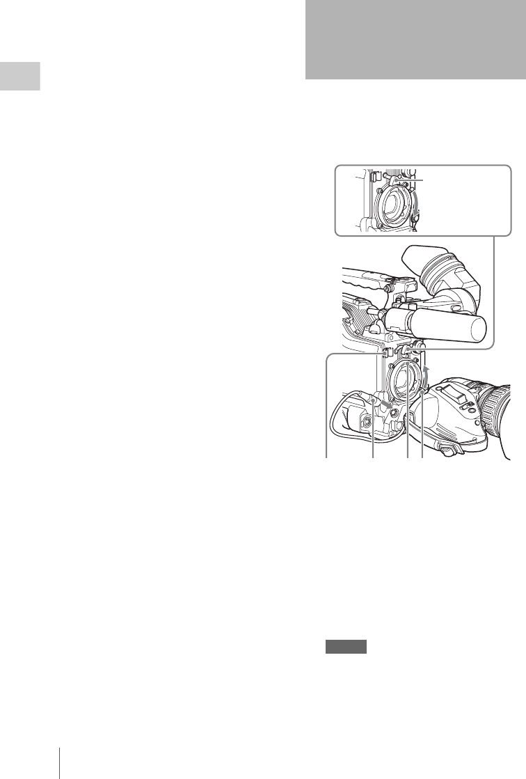
Mounting the Lens
42
Chapter 2 Preparations
4Turn the MENU knob to display the
desired value, and press the MENU
knob.
z changes to b and ? changes to z.
5To continue the remaining settings,
repeat steps 3 and 4.
6When you finish settings, turn the
MENU knob to move b to “OK”, then
press the MENU knob.
The internal clock is set with the date and
time set in steps 3 to 5. The TIME/DATE
page of the DIAGNOSIS menu appears
again. The time set on the TIME ADJUST
setting window is displayed.
To cancel the setting
Before executing step 6, move b to “ESC” at the
top right of the window and press the MENU
knob.
Alternatively, flick the CANCEL/PRST /
ESCAPE switch down to the ESCAPE side.
All settings or changes are discarded and the
TIME/DATE page of the DIAGNOSIS menu
appears.
First power off the camcorder, and then mount the
lens using the following procedure.
For information about using the lens, refer to the
operation manual for the lens.
1Push the lens locking lever up and
remove the lens mount cap from the
lens mount.
2Align the center pin on the lens with the
center slot in the lens mount, and insert
the lens into the mount.
3Holding the lens in place, push the lens
locking lever down to lock the lens.
Caution
If the lens is not firmly locked, it may come off
while the camcorder is being used. This could cause
a serious accident. Make sure the lens is firmly
locked. It is recommended that the lens mount
Mounting the Lens
3
1
2
4
5
Lens mount
securing rubber

Adjusting the Flange Focal Length 43
Chapter 2 Preparations
securing rubber be put on the lens locking lever as
illustrated above.
4Connect the lens cable to the LENS
connector.
5Secure the lens cable with the cable
clamps. If the lens does not stay in focus properly as you
zoom from telephoto to wide angle, adjust the
flange focal length (the distance from the plane of
the lens mounting flange to the imaging plane).
Make this adjustment after mounting or changing
the lens.
The position of the controls for adjusting the flange
focal length vary somewhat from lens to lens. Check
the identification of the various controls in the lens
manual.
1Set the iris to manual.
2Open the iris. Place the flange focal
length adjustment chart about 3 m (10
ft) away from the camera, lit well
enough to provide a satisfactory video
output level.
3Loosen the fixing screws on the F.f or
F.B ring (flange focal length adjustment
ring).
4Use manual or power zoom to set the
lens to telephoto.
5Point the camera at the chart by turning
the focus ring and focus on it.
6Set the zoom ring to wide angle.
7Turn the F.f or F.B ring until the chart
is in focus, being careful not to disturb
the focus ring.
Adjusting the Flange
Focal Length
About 3 m
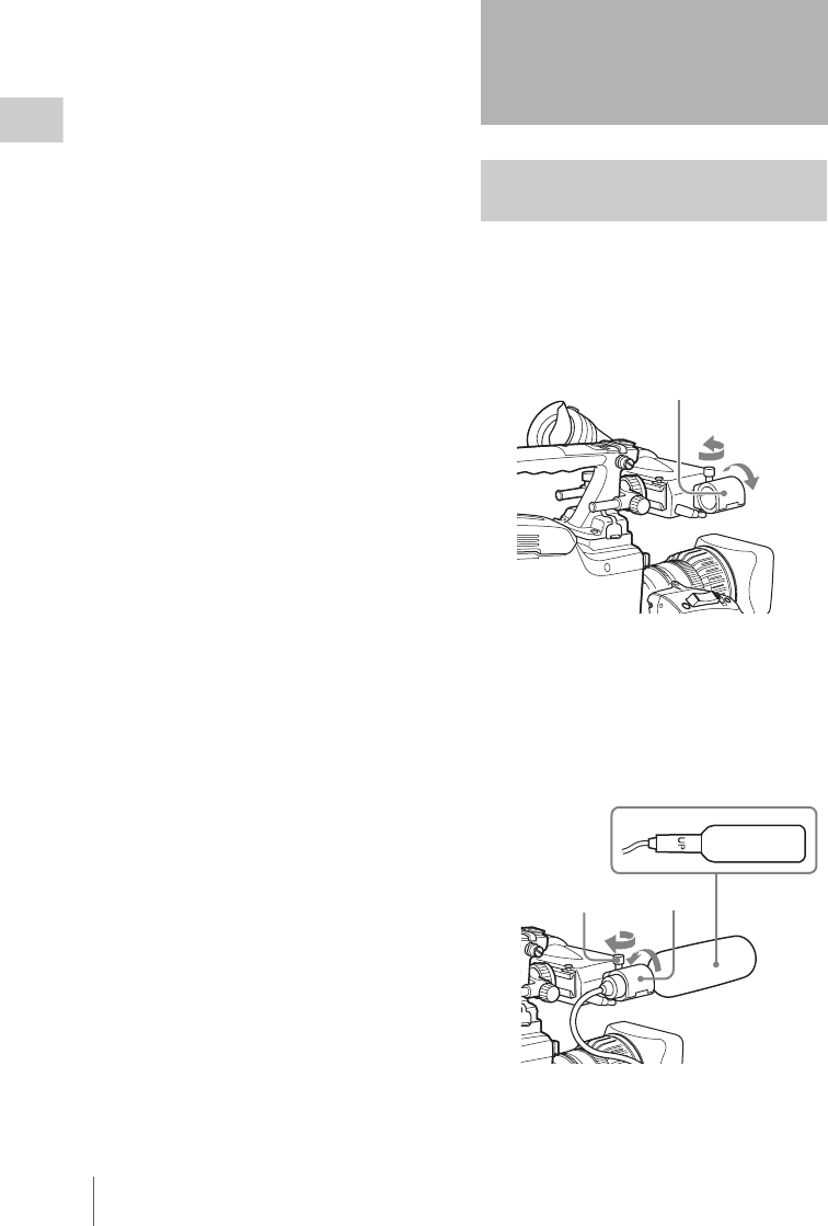
Preparing the Audio Input System
44
Chapter 2 Preparations
8Repeat steps 4 to 7 until the chart stays
in focus all the way from wide angle to
telephoto.
9Tighten the F.f or F.B ring fixing
screws.
You can attach the ECM-680S stereo microphone
(not supplied) to the microphone holder of the
HDVF-20A viewfinder (not supplied).
1Loosen the screw and open the
microphone holder clamp.
2Place the microphone in the
microphone holder.
1Place the microphone in the holder so
that “UP” is at the top.
2Close the microphone holder.
3Tighten the screw.
On how to perform this operation, refer to the
operation manual for the microphone.
Preparing the Audio
Input System
Connecting a microphone to the
MIC IN connector
1
2
Microphone holder clamp
1
23
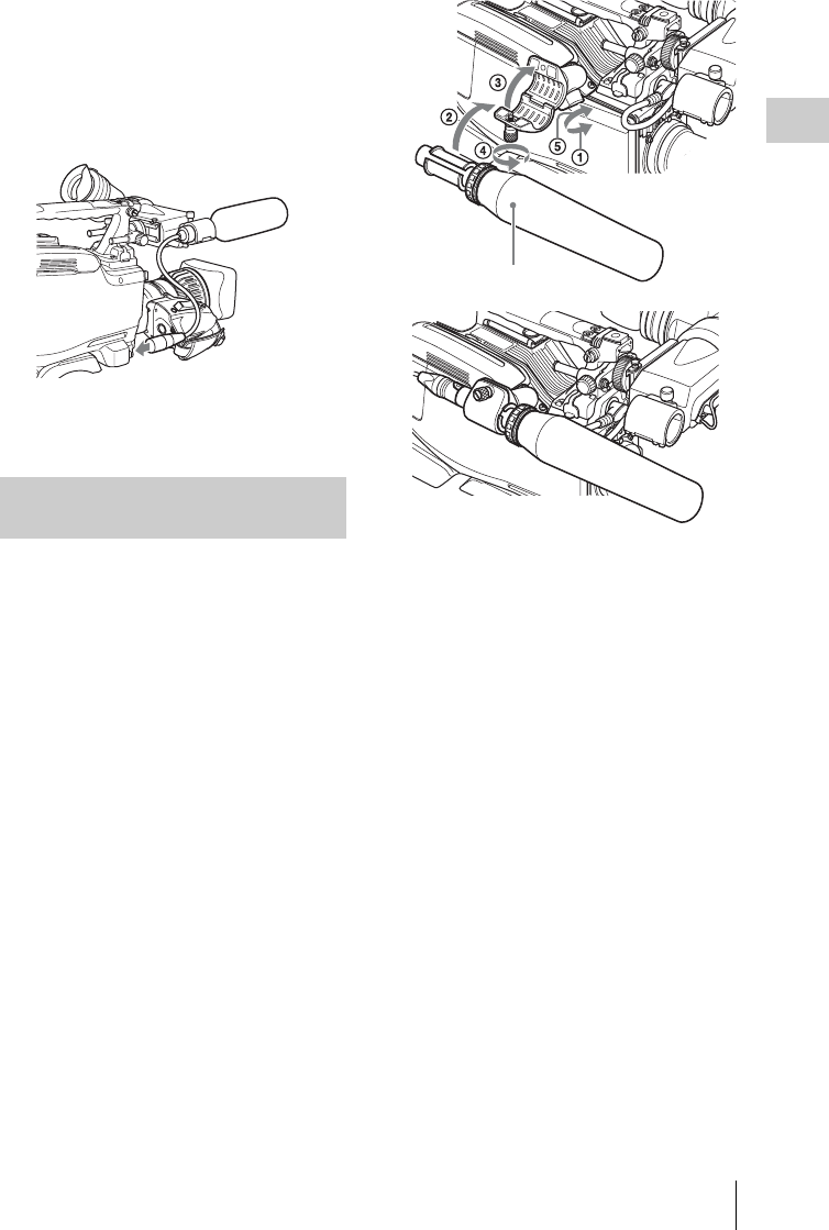
Preparing the Audio Input System 45
Chapter 2 Preparations
3Plug the microphone cable into the MIC
IN connector, then set the AUDIO IN
switch for the channel on which you
want to record the audio from this
microphone to FRONT (for CH-1/
CH-2) or F (for CH-3/CH-4).
4Secure the microphone cable with the
cable clamps.
You can connect up to two monaural
microphones to the AUDIO IN CH-1/CH-2
connectors, using a CAC-12 Microphone Holder
(not supplied).
The following is the procedure for attaching an
electret condenser microphone such as the ECM-
674/678.
On how to attach the CAC-12, refer to the operation
manual for the CAC-12.
1Attach the electret condenser
microphone.
1Loosen the ball joint lock lever.
2Place the microphone in the holder so
that “UP” is at the top.
3Close the microphone holder.
4Tighten the screw.
5Position so that the microphone does
not interfere with the viewfinder and
tighten the ball joint lock lever.
When attaching the ECM-674/678, use the
microphone adaptor supplied with the CAC-
12 Microphone Holder.
2Connect the microphone cable to the
AUDIO IN CH-1 or CH-2 connector.
3Set the switches as follows.
Set the LINE/AES/EBU/MIC switch to MIC.
• Set the +48V/OFF switch as indicated
below, depending on the power supply type
of the microphone.
Internal power supply: Set the +48V/OFF
switch to OFF.
External power supply: Set the +48V/
OFF switch to +48V (ON).
• Set the AUDIO IN (CH-1/CH-2/CH-3/CH-
4) switch for the channel to which the
microphone is connected to REAR (for
CH-1/CH-2) or R (for CH-3/CH-4).
Connecting microphones to the
AUDIO IN connectors
Microphone
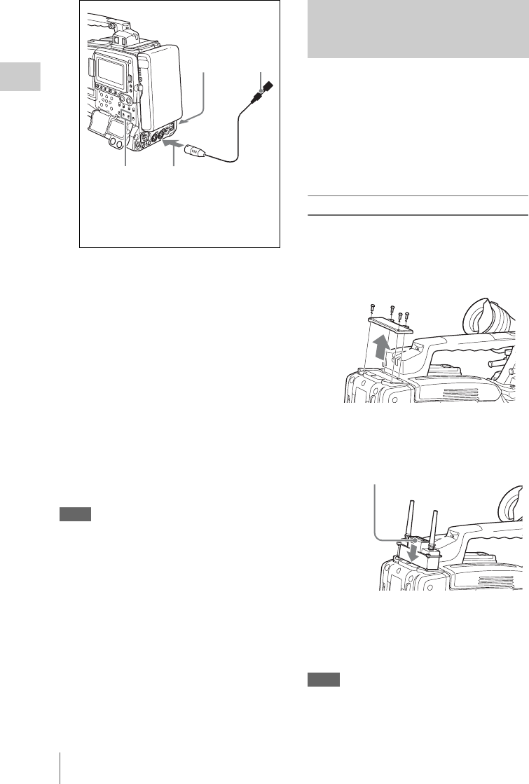
Preparing the Audio Input System
46
Chapter 2 Preparations
4Switch the input level to match the
sensitivity of the microphone used.
Switch the input level by changing the REAR
MIC REF setting on the AUDIO-1 page of the
MAINTENANCE menu (factory default setting
is –60 dB). For details, see page 149.
XLR connection automatic detection function
With the XLR connection automatic detection
function being on, when a cable is connected to
the AUDIO IN CH1 or CH2 connector, the input
from that connector is automatically selected for
audio recording, regardless of the setting of the
AUDIO IN CH-1 or CH-2 switch.
The XLR connection automatic detection
function can be switched on or off on the
AUDIO-1 page of the MAINTENANCE menu,
with the REAR XLR AUTO item.
Notes
• If the input level on this unit is not at an appropriate
setting for the microphone sensitivity, loud sounds
may be distorted, and the signal-to-noise ratio may be
affected.
• In order for the AUDIO IN CH-1 and CH-2 connectors
on the camcorder to be able to provide a phantom 48 V
power supply, female XLR connectors (3-pin) are
fitted. If the microphone cable has a female connector,
use an adaptor.
• When you detach a CAC-12 Microphone Holder once
you have attached to the camcorder, be careful not to
lose the two screws fixing the CAC-12 (in step 1).
After detaching the CAC-12, be sure to put the two
screws back into their original places.
To use a Sony UHF wireless microphone system,
fit one of the following UHF portable tuners.
• DWR-S01D Digital Wireless Receiver
• WRR-855S UHF Synthesized Tuner Unit
• WRR-860A/861/862 UHF Synthesized
Diversity Tuner
For details of these units, refer to the operation
manuals for them.
To fit the DWR-S01D or WRR-855S
1Remove the four fixing screws holding
the cover of the portable tuner/receiver
housing slot located in the rear of this
unit, to remove the cover.
2Insert the DWR-S01D or WRR-855S
into the housing slot, and fasten the four
fixing screws.
3Set the AUDIO IN switch for the
channel to which you want to input
audio signal to WIRELESS (see page
27).
Notes
• When the XLR connection automatic detection
function is on, even if the AUDIO IN CH-1 or CH-2
switch is set to WIRELESS, the signal input to the
12
43
1+48V/OFF switch
2Monaural microphone
3AUDIO IN CH-1/CH-2 switches
4To AUDIO IN CH1 or CH2 connector
Attaching a UHF portable tuner
(for a UHF wireless microphone
system)
DWR-S01D or WRR-855S
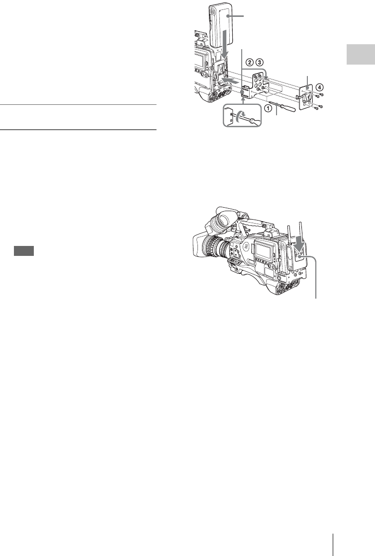
Preparing the Audio Input System 47
Chapter 2 Preparations
AUDIO IN CH1 or CH2 connector is automatically
selected when an audio cable is connected to the
AUDIO IN CH1 or CH2 connector. In such a case, set
REAR XLR AUTO to OFF on the AUDIO-1 page of
the MAINTENANCE menu. (The factory default
setting is OFF.)
• When the LINE/AES/EBU/MIC switch is set to LINE
or MIC, the audio signals recorded on audio channels
3 and 4 are not affected by the XLR automatic
detection function. They are determined by the settings
of the AUDIO IN CH-3 and CH-4 switches.
To fit the WRR-862 (when using a BP-
GL65/GL95/L60S/L80S Battery Pack)
1Attach the WRR tuner fitting (not
supplied; service part number: A-8278-
057-B) to the back of the camcorder.
1Use a Phillips type screwdriver to
tighten the four screws placed in the
tuner fitting. For three of these screws,
insert the screwdriver through the
corresponding hole and tighten the
screw.
Note
Make sure that all four screws are fully tightened.
2Loosen the adjustment screws on the
tuner fitting.
3Adjust the tuner fitting position for a
BP-GL65/GL95/L60S/L80S Battery
Pack to be attached, and tighten the
adjustment screws to fix its position.
4Attach the mount plate supplied with
the WRR-862.
About the WRR tuner fitting (service part
number: A-8278-057-B), contact a Sony service
or sales representative.
2Attach the battery pack.
On how to attach the battery pack, see “To
attach the battery pack” on page 35.
3Mount the tuner on the WRR tuner
fitting.
4Connect the tuner power cord to the DC
OUT connector of the camcorder, and
the audio output cable to the AUDIO IN
CH1 or CH2 connector.
5Set the switches as follows.
• Set the LINE/AES/EBU/MIC switch for
the channel to which the audio output cable
is attached to MIC.
• Set the AUDIO IN (CH-1/CH-2/CH-3/CH-
4) switch for the channel to which the audio
output cable is connected to REAR (for
CH-1/CH-2) or R (for CH-3/CH-4).
If the XLR connection automatic detection
function is on, the input signal for audio
recording is selected automatically, and
therefore this setting is not required.
BP-GL65/GL95/L60S/L80S
Adjustment
screws
Mount plate
(supplied with
WRR-862)
Phillips type
screwdriver
WRR-862
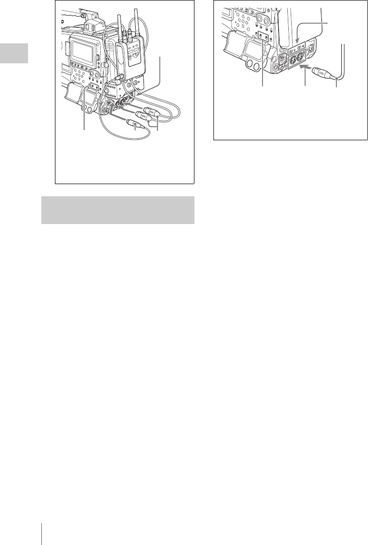
Preparing the Audio Input System
48
Chapter 2 Preparations
Connect the audio output connector of the audio
equipment that supplies the line input signal to the
AUDIO IN CH1 or CH2 connector.
Switch settings
Set the LINE/AES/EBU/MIC switch for the
channel to which the audio signal source is
connected to “LINE”.
Selecting the audio inputs to be recorded
• With the XLR connection automatic detection
function being off (the factory default setting):
A signal must be selected for audio recording by
setting the AUDIO IN CH-1 or CH-2 switch to
“REAR” depending on which of the AUDIO IN
CH1 and CH2 connectors is used for connecting
the external audio equipment.
• With the XLR connection automatic detection
function being on: When a cable is connected to
the AUDIO IN CH1 or CH2 connector, the
input from that connector is automatically
selected for audio recording, regardless of the
setting of the AUDIO IN CH-1 or CH-2 switch.
The XLR connection automatic detection
function can be switched on or off on the
AUDIO-1 page of the MAINTENANCE menu,
with the REAR XLR AUTO item.
Connecting line input audio
equipment
123
4
1AUDIO IN CH-1/CH-2 switches
2To DC OUT connector
3To AUDIO IN CH1 or CH2 connector
4LINE/AES/EBU/MIC switch
21 3
4
1AUDIO IN CH-1/CH-2 switches
2To AUDIO IN CH1 or CH2 connector
3Audio equipment
4LINE/AES/EBU/MIC switch
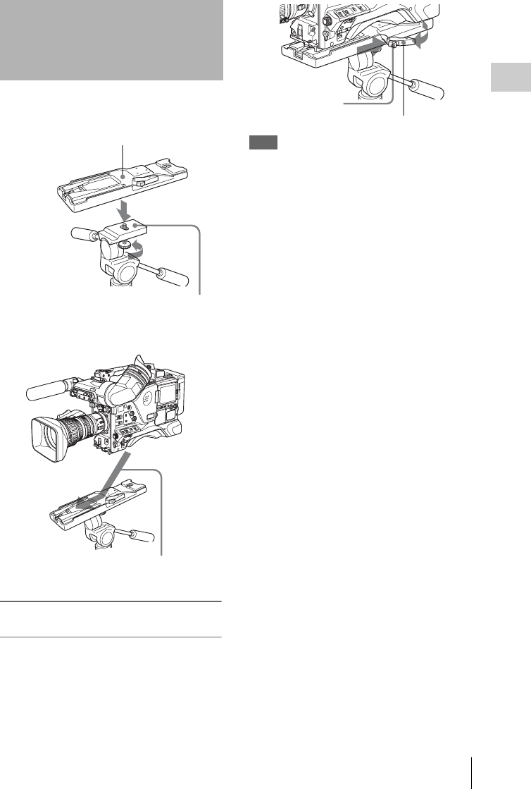
Tripod Mounting 49
Chapter 2 Preparations
1Attach the VCT-14 tripod adaptor (not
supplied) to the tripod.
2Mount the camcorder on the tripod
adaptor.
To remove the camcorder from the tripod
adaptor
Hold down the red button and pull the lever in the
direction of the arrow.
Note
The tripod adaptor pin may remain in the engaged
position even after the camcorder is removed. If this
happens, press the red button against the lever a second
time and move the lever as shown above until the pin
returns to the stowed position. If the pin remains in the
engaged position, you will not be able to mount the
camcorder on the tripod adaptor.
Tripod Mounting
Tripod adaptor
Camera mount
Slide the camcorder forward along the
groove in the adaptor until it clicks
Red button
Lever
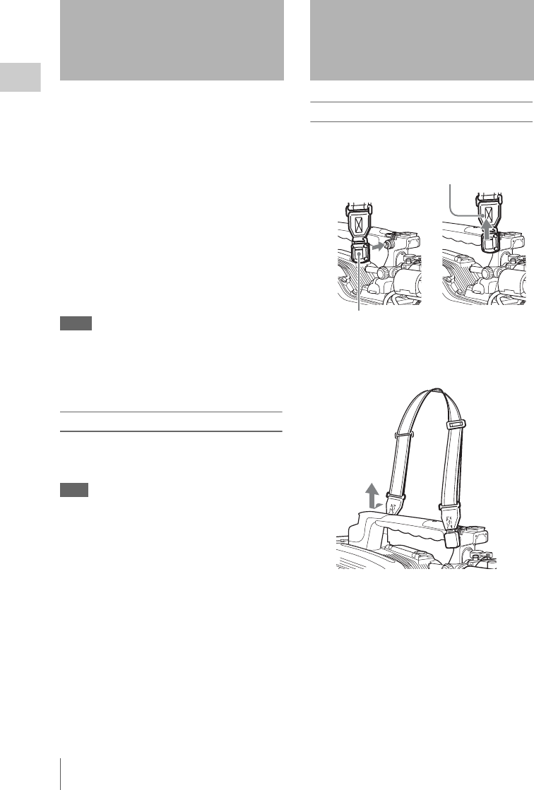
Connecting a Video Light / Using the Shoulder Strap
50
Chapter 2 Preparations
With this camcorder, you can use the Anton
Bauer Ultralight 2 or equivalent video light
(powered by 12 V with maximum power
consumption of 50 W).
• If you connect the video light to the LIGHT
connector on the camcorder and set the LIGHT
switch to AUTO, you can turn the light on and
off automatically as you start and stop the VDR
operation.
• The output of the LIGHT connector on the
camcorder is controlled to 12 V even when the
camcorder is supplied with over 12 V power
(through the DC IN connector or battery pack).
The brightness or color temperature of the light
will not change according to voltage increase.
Notes
• Do not use a video light with power consumption of
over 50 W.
• The brightness or color temperature of the light will
change when the voltage (supplied through the DC IN
connector or from the battery pack) is under 12 V.
To attach the video light
Fit the video light to the accessory fitting shoe on
the camcorder grip, and connect the video light
cable to the LIGHT connector.
Note
The accessory fitting shoe on this unit is of the 1/4-inch
tapped hole type. If you want to replace this with a slide-
type shoe, contact a Sony service representative.
To attach the shoulder strap
1Fit one of the clips to a shoulder strap
fitting.
2Fit the other clip to the shoulder strap
fitting on the other side of the grip in the
same way as in step 1.
Connecting a Video
Light
Using the Shoulder
Strap
g
Clip
Pull up the strap to lock the fitting
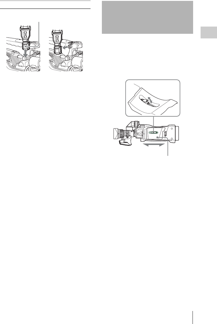
Adjusting the Shoulder Pad Position 51
Chapter 2 Preparations
To remove the shoulder strap
You can shift the shoulder pad from its center
position (the factory default setting) backward by
up to 10 mm (3/8 inch) or forward by up to 25 mm
(1 inch). This adjustment helps you get the best
balance for shooting with the camcorder on your
shoulder.
1Raise the lever in the center of the
shoulder pad to unlock the shoulder
pad.
2Slide the shoulder pad backward or
forward until it is in the most
convenient position.
3Bring down the lever to lock the
shoulder pad in the selected position.
g
Press here and pull in the direction
shown by the arrow to release
Adjusting the Shoulder
Pad Position
1,3
2
Shoulder pad
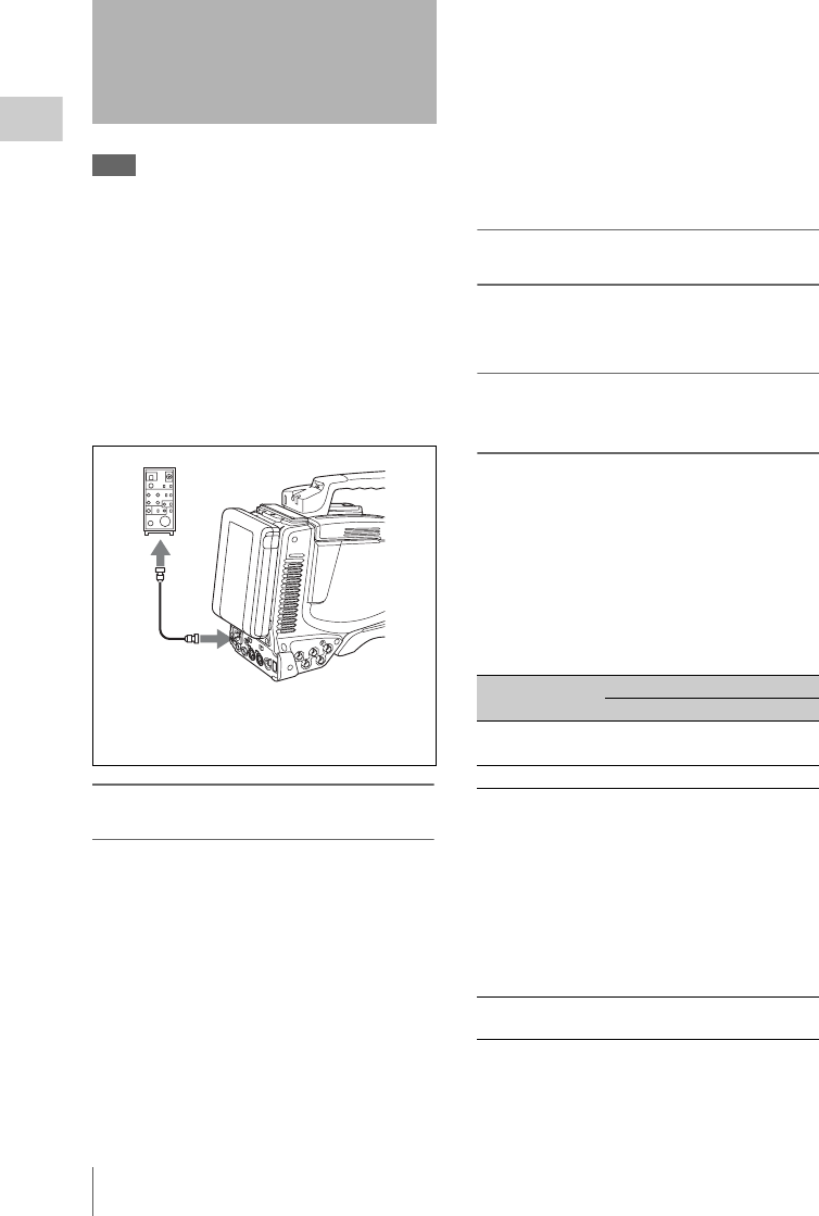
Connecting the Remote Control Unit
52
Chapter 2 Preparations
Note
Before connecting/disconnecting a remote control unit
to/from the camcorder, be sure to turn the power of the
camcorder off.
Connecting the RM-B150/B750 Remote Control
Unit enables remote control of the principal
camera functions.
Connecting the remote control unit to the
REMOTE connector (8-pin) automatically puts
the camcorder into remote control mode. If you
disconnect the remote control unit, the remote
control mode is cancelled.
Camcorder switch functions when the
remote control unit is connected
The following switches on the camcorder do not
function.
•GAIN selector
•OUTPUT/DCC switch
•WHITE BAL switch
•AUTO W/B BAL switch
• SHUTTER selector
• Button to which the TURBO SWITCH function
has been assigned (ASSIGN 1/3/4 switch,
COLOR TEMP. button, or RET button on the
lens)
• REC START button (and the VTR button on the
lens, and the button to which the recording start/
stop function has been assigned (ASSIGN 1/3/4
switch, COLOR TEMP. button, or RET button
on the lens)) (when the RM REC START item
on the CAM CONFIG 2 page of the
MAINTENANCE menu is set to RM)
• Buttons to which the COLOR TEMP SW
3200K/4300K/5600K/ 6300K functions have
been assigned (ASSIGN 1/3/4 switches,
COLOR TEMP. button, and RET button on the
lens)
Paint adjustment when the remote
control unit is connected
The settings of the paint adjustment that were in
effect the last time the remote control unit was
used are recalled.
Function of the recording start/stop
buttons when the remote control unit is
connected
When the remote control unit is connected, you
can make a setting to determine which of the
recording start/stop buttons you will use. This
setting is made using the RM REC START item
on the CAM CONFIG 2 page of the
MAINTENANCE menu.
Relationship between the setting of the RM REC
START item and the function of recording start/
stop buttons
Connecting the Remote
Control Unit
1
2
3
1RM-B150/B750
2Remote control cable
3REMOTE connector
Recording start/
stop button
Settings of RM REC START
RM CAM PARA
Camcorder’s REC
START button
Disabled Enabled Enabled
Lens VTR button Disabled Enabled Enabled
Button to which
the recording
start/stop function
has been assigned
(camcorder
ASSIGN 1/3/4
switch or COLOR
TEMP. button, or
RET button on
the lens)
Disabled Enabled Enabled
Remote control
unit’s VTR button
Enabled Disabled Enabled
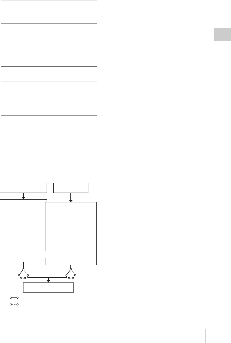
Connecting the Remote Control Unit 53
Chapter 2 Preparations
When the monitor is connected to the
MONITOR OUT connector of the remote
control unit
The MONITOR connector (BNC type) of the
RM-B150/B750 outputs the same signal as that
from the TEST OUT connector on the camcorder.
Use the black cable supplied with the RM-B150/
B750 to connect the monitor to the MONITOR
connector on the RM-B150/B750.
When the remote control unit is
disconnected from the camcorder
The camcorder settings return to the settings in
effect before the remote control unit was
connected.
Structure of the paint adjustment data
The non-volatile memory of the camcorder used
for storing paint adjustment data consists of two
regions as shown below: one is the “independent
data region” that is used when a remote control
unit is not connected, and the other is the “remote
control data region” that is used when a remote
control unit is connected. Paint adjustment data is
automatically selected and output to the camera
section depending on whether or not a remote
control unit such as the RM-B150 is connected.
Thus, when a remote control unit is connected to
the camcorder, the effective data region is
switched to the “remote control data region” and
the settings of the paint adjustment that were in
effect the last time the remote control unit was
used are recalled.
The settings of the absolute value rotational
controls 1) and absolute value switches 2) are
overwritten by those on the remote control unit
after the remote control unit is connected.
When the remote control unit is disconnected
from the camcorder, the “independent data
region” becomes effective. Thus the camcorder
will return to the settings that were in effect
before the remote control unit was connected.
1) Absolute value rotational controls: The data
corresponding to the angular position of controls is
output. Rotational controls for which the data
corresponding to the amount of their rotation is output
are called relative value controls.
2) Absolute value switches: Like toggle switches or
slide switches (except momentary switches), the
switches (or knobs) whose positions must coincide
with their functions are called absolute value switches.
When RM COMMON MEMORY is set to “ON”
on the CAM CONFIG 2 page of the
MAINTENANCE menu, you can use settings of
the paint adjustment data stored in the
independent data region even if you connect the
remote control unit. In this case, the settings
stored in the independent data region will be
renewed when you change the settings on the
remote control unit. Thus, the settings of the paint
data made with the remote control unit can be
retained even if the remote control unit is
removed. However, if the switch position on the
remote control unit differs from the one on the
camcorder, the switch position on the camcorder
takes precedence over that on the remote control
unit.
Also, it is possible to keep the settings that are in
effect before you connect the remote control unit.
In this case, you should set the control knob to the
relative value mode on the remote control unit.
For details, refer to the operation manual supplied
with the remote control unit.
RM-B150
MASTER BLACK
MASTER GAMMA
KNEE POINT
DETAIL LEVEL
R/B GAIN
R/B BLACK
MASTER BLACK
MASTER GAMMA
KNEE POINT
DETAIL LEVEL
R/B GAIN
R/B BLACK
Hardware of the
camera section
RM-B150 connected
RM-B150 not connected
Independent
data region Remote control
data region
Setup menu of the
camcorder
Non-volatile memory

Setting the Recording Format
54
Chapter 3 Adjustments and Settings for Shooting
The recording formats supported by this
camcorder are as follows.
Video
a) 59.94i/29.97P/59.94P: When the area of use is set to
NTSC (J) AREA/NTSC AREA.
50i/25P/50P: When the area of use is set to PAL
AREA.
b) When the optional CBKZ-MD01 SD Record and
Playback Software is installed.
Audio
a) When the video recording format is set to MPEG
HD422 50.
b) When the video recording format is set to MPEG IMX
50/40/30.
c) When the video recording format is set to MPEG
HD420 HQ/SP or DVCAM.
Notes
• It is not possible to combine material recorded in
different system frequencies and recording formats on
a single disc (although 1080/50i and 1080/25P
materials can be combined).
• This unit can record up to four channels of audio. If
you select a format with eight channels of audio,
silence is recorded in channels 5 to 8.
1Display the FORMAT page of the
OPERATION menu.
For details on menu operations, see “Basic
menu operations” on page 163.
2Select SYSTEM FREQUENCY, and
turn the MENU knob to select the
desired system frequency.
You can select the frequency shown below
depending on the combination of the
COUNTRY and SYSTEM LINE settings.
• Change the COUNTRY or SYSTEM LINE
setting as required.
• When SYSTEM LINE is set to 720 and
SYSTEM FREQUENCY is set to 59.9P,
you can set the camera shooting frequency
(SCAN MODE) to either 59.9 Hz or 23.9
Hz. Set SCAN MODE to either as required.
Chapter3
Adjustments and Settings for Shooting
Setting the Recording
Format
Recording format Resolution System
frequency a)
MPEG HD422 50
(Bit rate: 50 Mbps)
1080 59.94i/29.97P/
50i/25P
720 59.94P/50P
MPEG HD420 HQ/
SP
(Bit rate: 35/25
Mbps)
1080 59.94i/50i
720 59.94P/50P
MPEG IMX 50/40/
30 b)
(Bit rate: 50/40/30
Mbps)
525 59.94i
625 50i
DVCAM b)
(Bit rate: 25 Mbps)
525 59.94i
625 50i
Recording format Number of channels
24bit/48kHz 8 channels a)
4 channels b)
16bit/48kHz 8 channels b)
4 channels c)
Setting the system frequency
COUNTRY SYSTEM
LINE
SYSTEM
FREQUENCY
NTSC(J)AREA
NTSC AREA
1080 59.9i/29.9P
720 59.9P
PAL AREA 1080 50i/25P
720 50P
SYSTEM LINE : 1080
SYSTEM FREQUENCY: 59.9i
REC FORMAT : HD422 50
COUNTRY : NTSC(J)AREA
024
FORMAT TOP

Adjusting the Black Balance and the White Balance 55
Chapter 3 Adjustments and Settings for Shooting
Note
When you set SCAN MODE to 23.9P, the video
output signals and video recording signals of this
unit are 59.9 Hz signals after 2-3 pulldown.
1Display the FORMAT page of the
OPERATION menu.
For details on menu operations, see “Basic
menu operations” on page 163.
2Select REC FORMAT, and turn the
MENU knob to select the desired
recording format.
As you turn the MENU knob, the recording
format changes as follows: HD422 50 y
HD420 HQ y HD420 SP y IMX 50 1)
y IMX 40 1) y IMX 30 1) y
DVCAM 1).
1) When the optional CBKZ-MD01 SD Record and
Playback Software is installed.
To set the aspect ratio (when IMX 50, IMX 40,
IMX 30, or DVCAM is selected)
Select ASPECT RATIO(SD) on the FORMAT
page, and turn the MENU knob to select the
desired aspect ratio.
As you turn the MENU knob, the aspect ratio
changes as follows: 16:9 y 4:3.
Note
The unit ignores this setting when it records video from
external devices (see page 93).
To set the audio recording format (when IMX 50,
IMX 40, or IMX 30 is selected)
Select AU DATA LEN(IMX) on the FORMAT
page or AUDIO-2 page of the MAINTENANCE
menu, and turn the MENU knob to select the
desired audio recording format.
As you turn the MENU knob, the audio recording
format changes as follows: 16bit y 24bit.
To ensure excellent image quality when using this
camcorder, conditions may require that both the
black balance and the white balance be adjusted.
Black balance adjustment
The black balance will require adjustment in the
following cases.
• When the camcorder is used for the first time
• When the camcorder has not been used for a
long time
• When the camcorder is used under conditions in
which the surrounding temperature has changed
greatly
• When the GAIN selector (L/M/H) values have
been changed by using the USER menu
It is not usually necessary to adjust the black
balance when using the camcorder after it has
been off.
White balance adjustment
Always readjust the white balance when the
lighting conditions change.
Viewfinder screen displays
If the black balance or white balance adjustment
is started, messages that report on the progress
and results are displayed on the viewfinder screen
when the VF DISP MODE item is set to “2” or
“3” on the VF DISP 1 page of the USER menu.
Note
Black balance and white balance adjustment values that
are automatically set by the camcorder and the various
settings are stored in the camcorder memory and retained
even when the power is turned off.
In automatic black balance mode, adjustments are
performed in the following order: black set and
black balance. Manual black balance adjustment
can be selected from the setup menu.
For details of manual black balance adjustment,
refer to the Maintenance Manual.
Setting the video recording format
SYSTEM LINE : 1080
SYSTEM FREQUENCY: 59.9i
REC FORMAT : IMX 50
ASPECT RATIO(SD): 16:9
AU DATA LEN(IMX): 16bit
COUNTRY : NTSC(J)AREA
024
FORMAT TOP
Adjusting the Black
Balance and the White
Balance
Adjusting the black balance
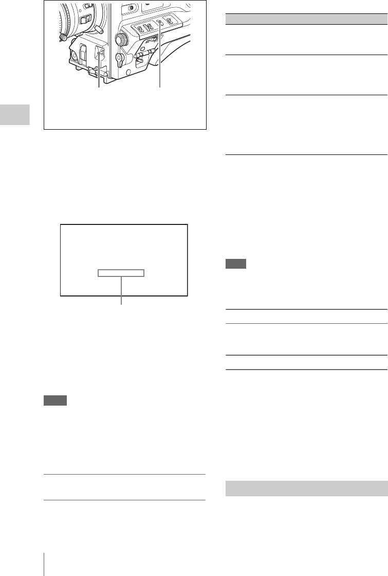
Adjusting the Black Balance and the White Balance
56
Chapter 3 Adjustments and Settings for Shooting
1Set the OUTPUT/DCC switch to CAM.
2Flick the AUTO W/B BAL switch to
BLK and release the switch.
The switch returns to the center position, and
the adjustment is executed.
During adjustment, the following message is
displayed on the viewfinder screen.
The black balance adjustment ends in a few
seconds with the message “ABB:OK” and
the adjustment value is automatically stored
in memory.
Notes
• During the black balance adjustment, the iris is
automatically closed.
• During the black balance adjustment, the gain
selection circuit is automatically activated so you may
see flickering on the viewfinder screen, but this is not
a fault.
If automatic black balance adjustment
cannot be made
If the black balance adjustment cannot be
completed normally, an error message will appear
for about 3 seconds on the viewfinder screen.
Possible messages are listed below.
If any of the above error messages is displayed,
retry the black balance adjustment.
Keep pushing the AUTO W/B BAL switch to
BLK until “-BLACK SET-” appears after “-
BLACK BALANCE-” appears. If the error
message occurs again, an internal check is
necessary.
For information about this internal check, refer to
the Maintenance Manual.
Note
If the lens cable is not firmly connected to the LENS
connector, it may not be possible to adjust the lens iris.
If this happens, the black balance will be incorrect.
Black balance memory
Values stored in memory are held until the black
balance is next adjusted.
If a memory error occurs
If the error message “: STORED DATA : NG”
flashes on the viewfinder screen when the
camcorder is turned on, the black balance and
white balance memory contents have been lost.
Adjust the black balance and white balance again.
Contact a Sony representative if this message
continues to appear even after the black balance
and white balance have been adjusted again.
For details, refer to the Maintenance Manual.
1Set the switches and selectors as shown
in the figure below.
21
1OUTPUT/DCC switch
2AUTO W/B BAL switch
ABB:EXECUTING
BLACK SET
The messages change in the following
sequence :
BLACK SET
r
BLACK BALANCE
Error message Meaning
ABB : NG
IRIS NOT CLOSE
The lens iris did not close;
adjustment was
impossible.
ABB : NG
TIME LIMIT
Adjustment could not be
completed within the
standard number of
attempts.
ABB : NG
R (or G or B) :
OVERFLOW
The difference between the
reference value and the
current value is so great
that it exceeds the range.
Adjustment was
impossible.
Adjusting the white balance
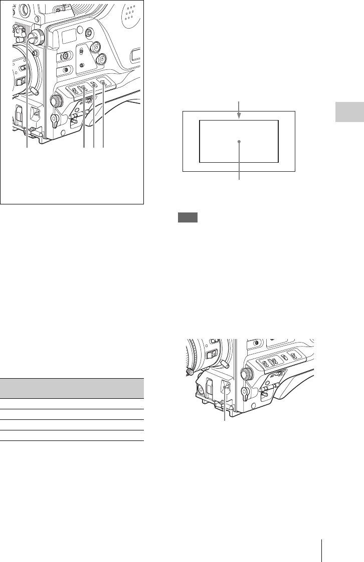
Adjusting the Black Balance and the White Balance 57
Chapter 3 Adjustments and Settings for Shooting
a)White balance setting values are stored in
memory B only when the WHITE SWITCH <B>
item is set to “MEM” on the WHITE SETTING
page of the OPERATION menu.
If the setting of the GAIN selector or WHITE
BAL switch is changed, a message reporting
the new setting position appears for about 3
seconds in the setting change and adjustment
progress message display area of the
viewfinder screen.
2Set the FILTER selector to suit the
lighting conditions as follows.
The possible settings of the FILTER selector
and their corresponding filters to be selected
are listed below.
If the setting of the FILTER selector is
changed, a message reporting the setting
appears for about 3 seconds in the setting
change and adjustment progress message
display area of the viewfinder screen (in
display mode 3).
3Place a white test card under the same
lighting conditions as for the subject to
be shot and zoom up to it.
Alternatively, any white object such as a
cloth or a wall can be used.
The absolute minimum white area is as
follows.
Note
Make sure there are not bright spots in the
rectangle.
4Adjust the lens iris.
Manually adjusted lens: set the iris to an
appropriate setting.
Lens with automatic iris: set the automatic/
manual switch on the lens to automatic.
5Flick the AUTO W/B BAL switch to
WHT and then release the switch.
The switch returns to the center position, and
the adjustment is executed.
During adjustment, the message “WHITE :
OP” is displayed on the viewfinder screen (in
display mode 2 or 3).
The white balance adjustment ends in about
one second with the message shown in the
FILTER selector (inner knob)
setting
ND filter
1 CLEAR
21/4 ND
31/16 ND
41/64 ND
2341
1FILTER selector
2GAIN selector: Set as low as possible.
3OUTPUT/DCC switch: CAM
4WHITE BAL switch: A or B a)
The white object must be within the
rectangle and have an area of at least 10%
of the screen.
Rectangle centered on the screen. The
lengths of the sides are 70% of the length
and width of the screen.
AUTO W/B BAL switch

Adjusting the Black Balance and the White Balance
58
Chapter 3 Adjustments and Settings for Shooting
following figure, and the adjustment setting
is automatically stored in the memory (A or
B) that was selected in step 1.
Note
If the camera has a zoom lens with an automatic iris,
the iris may hunt 1) during the adjustment. To
prevent this, adjust the iris gain knob (indicated as
IG, IS, or S) on the lens.
For details, refer to the lens operation manual.
1) Hunting: Repeated brightening and darkening of
the image, resulting from repeated response to
automatic iris control.
If the automatic white balance adjustment
cannot be made
If the white balance adjustment cannot be
completed normally, an error message will appear
for about 3 seconds on the viewfinder screen.
Possible messages are listed below.
If any of the above error messages is displayed,
retry the white balance adjustment. If the error
message occurs again, an internal check is
necessary.
For information about this internal check, refer to
the Maintenance Manual.
If you have no time to adjust the white
balance
Set the WHITE BAL switch to PRST.
This makes it possible to automatically set the
white balance to 5600K (factory default value) by
pressing the COLOR TEMP. button.
The color temperature to which the white balance
is set when the COLOR TEMP. button is pressed
can be selected from among 3200K, 4300K,
5600K, and 6300K on the ASSIGNABLE SW
page of the OPERATION menu. You can also
assign color temperatures to the ASSIGN 1/3/4
switches and the RET button on the lens.
For details of automatic white balance adjustment,
see page 56.
To change the color temperature when
the ND filter is switched
You can assign electrical CC (color correction)
filters to ND filters (see page 17). This allows you
AWB:OK
. K
Approximate color temperature
of the subject
Error message Meaning
WHITE : NG
LOW LEVEL
The white video level is
too low. Either open the
lens iris or increase the
gain.
WHITE : NG
COLOR TEMP
HIGH
The color temperature is
too high.
WHITE : NG
COLOR TEMP LOW
The color temperature is
too low.
WHITE : NG
TIME LIMIT
Adjustment could not be
completed within the
standard number of
attempts.
WHITE : NG
POOR WHITE
AREA
The white area could not
be checked.
WHITE : NG
OVER LEVEL
The white video level is
too high. Either stop down
the lens iris or change the
ND filter.

Adjusting the Black Balance and the White Balance 59
Chapter 3 Adjustments and Settings for Shooting
to change the color temperature automatically
when the ND filter is switched.
1Display the WHITE FILTER page of
the MAINTENANCE menu.
For details on menu operations, see “Basic
menu operations” on page 163
2Select ND FILTER CTEMP, and turn
the MENU knob to display “ON”.
3To assign an electrical CC filter to
FILTER selector position number 1,
select “ND FLT CTEMP <1>”. To
assign it to positions 2 to 4, select “ND
FLT CTEMP 2-4”.
4Turn the MENU knob to display the
desired color temperature.
As you turn the MENU knob, the color
temperature changes as follows: 3200K y
4300K y 5600K y 6300K.
5Repeat steps 3 and 4 as required.
To switch between electrical CC filters
with an ASSIGN switch
You can assign the function that switches
between electrical CC filters to an ASSIGN
switch. This allows you to switch between color
temperatures (3200K/4300K/5600K/6300K) that
have been assigned to up to four positions (A to
D) with each press of the ASSIGN switch.
Regardless of assignments to ASSIGN switches,
you can also switch between the color
temperatures assigned to each position from a
remote control unit. 1)
1) When the RM-B150/B750, MSU-900/950, or RCP-
750/751/920/921 is connected.
1Display the WHITE FILTER page of
the MAINTENANCE menu.
For details on menu operations, see “Basic
menu operations” on page 163.
2Select the position to which to assign a
CC filter by selecting one of
“ELECTRICAL CC<A>” to
“ELECTRICAL CC <D>”, and then
turn the MENU knob to select the
desired color temperature.
As you turn the MENU knob, the color
temperature changes as follows: 3200K y
4300K y 5600K y 6300K.
To set no color temperature
Select “-----” with ELECTRICAL CC<C> or
<D> selected.
When the ASSIGN switch is pressed, the
setting for that position is not displayed. For
example, if “-----” is set for one position, then
switching between the remaining three
positions is carried out.
3Repeat step 2 as required.
4Assign the electrical CC filter switching
function (ELECTRICAL CC) to an
ASSIGN 1/3/4 switch, the COLOR
TEMP button, or the RET button on the
lens (see page 178).
White balance memory
Values stored in memory are held until the white
balance is next adjusted.
There are two sets of white balance memories, A
and B, and adjustments for each of the ND filters
can be automatically stored in the memory
corresponding to the setting (A or B) of the
WHITE BAL switch. The camcorder has four
built-in ND filters, so a total of eight (4 × 2)
adjustments can be stored. However, the memory
contents are not linked to the ND filter settings in
the following cases.
• When the number of memories allocated to
each of A and B is limited to one by setting the
FILTER WHT MEM item on the WHITE
SETTING page of the OPERATION menu to
OFF.
• When the electrical CC filter switching function
has been assigned to an ASSIGN switch, or
when a remote control unit has been connected.
(In these cases, the contents of white balance
memory are linked to electrical CC filter
positions (A to D).)
If the WHITE BAL switch is set to B, and on the
WHITE SETTING page of the OPERATION
ND FILTER CTEMP : OFF
ND FLT CTEMP <1>: 3200K
ND FLT CTEMP 2-4: 5600K
ELECTRICAL CC<A>: 3200K
ELECTRICAL CC<B>: 4300K
ELECTRICAL CC<C>: 5600K
ELECTRICAL CC<D>: 6300K
M15
WHITE FILTER TOP

Setting the Electronic Shutter
60
Chapter 3 Adjustments and Settings for Shooting
menu, the WHITE SWITCH <B> item is set to
“ATW”, the ATW function is activated to
automatically adjust the white balance of the
picture being shot for varying lighting conditions.
If a memory error occurs
If the error message “: STORED DATA : NG”
flashes on the viewfinder screen when the
camcorder is turned on, the white balance and
black balance memory contents have been lost.
Adjust the white balance and black balance again.
Contact a Sony representative if this message
continues to appear even after the white balance
and black balance have been adjusted again.
For details, refer to the Maintenance Manual.
The shutter modes that can be used with the
electronic shutter and the shutter speeds that can
be selected are listed below.
Standard mode
Select this mode for shooting fast-moving
subjects with little blurring.
ECS (Extended Clear Scan) mode
Select this mode for obtaining images with no
horizontal bands of noise when shooting subjects
such as monitor screens.
Setting the Electronic
Shutter
Shutter modes
SYSTEM
LINE setting
System
frequency
Shutter speed
(unit: seconds)
1080 59.94i 1/100, 1/125, 1/250,
1/500, 1/1000, 1/2000
50i 1/60, 1/125, 1/250,
1/500, 1/1000, 1/2000
29.97P 1/40, 1/60, 1/120, 1/125,
1/250, 1/500, 1/1000,
1/2000
25P 1/33, 1/50, 1/100, 1/125,
1/250, 1/500, 1/1000,
1/2000
720 59.94P
(SCAN
MODE:
59.9P)
1/100, 1/125, 1/250,
1/500, 1/1000, 1/2000
59.94P
(SCAN
MODE:
23.9P)
1/32, 1/48, 1/50, 1/60,
1/96, 1/125, 1/250,
1/500, 1/1000, 1/2000
50P 1/60, 1/125, 1/250,
1/500, 1/1000, 1/2000
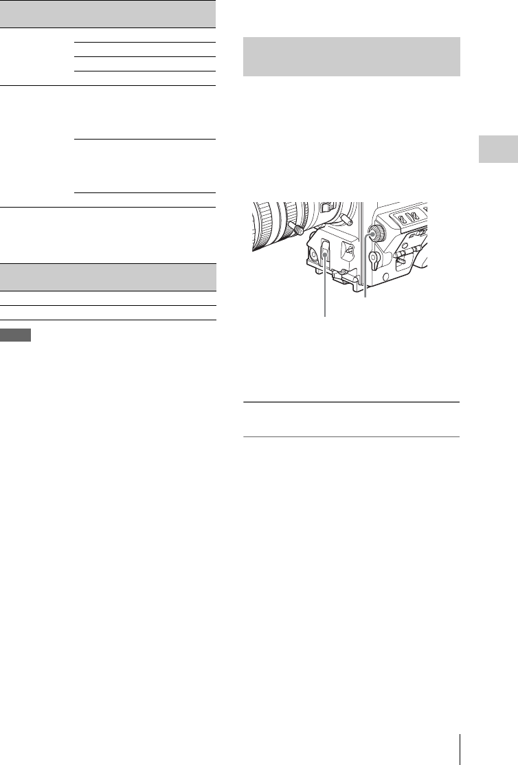
Setting the Electronic Shutter 61
Chapter 3 Adjustments and Settings for Shooting
SLS (slow speed shutter) mode
Select this mode for shooting subjects in low level
lighting conditions.
Notes
• SLS mode cannot be selected when SCAN
MODE is set to 23.9P.
• Whatever the operating mode of the electronic
shutter, the sensitivity of the CCD decreases
with increasing shutter speed.
• When the automatic iris is used, the iris opens
wider as the shutter speed increases, thus
reducing the depth of field.
• Under artificial light, particularly fluorescent or
mercury lamps, the light intensity may appear to
be constant, but the red, green, and blue
intensities are actually changing in
synchronization with the frequency of the
power supply causing flicker. Using an
electronic shutter under such lighting could
make the flicker even worse. Color flicker is
particularly likely to happen when the power
supply frequency is 60 Hz. However, if the
power frequency is 50 Hz, setting the shutter
speed to 1/100 can reduce this flicker.
• When a bright object is shot in ECS mode in
such a manner that it fills the screen, the upper
edge of the picture may have poor quality
because of an inherent characteristic of CCDs.
Before using ECS mode, check the shooting
conditions.
• The selectable shutter speeds vary depending on
the current system frequency.
Switching the shutter mode, and the shutter
speed in standard mode: Repeatedly flick
the SHUTTER selector to the SELECT side
(see the next section).
Switching the shutter speed in ECS mode and
SLS mode: Select ECS mode or SLS mode
with the SHUTTER selector, and then turn
the MENU knob (see page 62).
You can use the SHT ENABLE page of the
OPERATION menu to narrow the range of
choice in advance, or to select in advance whether
or not you use ECS or SLS.
To set the shutter mode and standard-
mode shutter speed
Once the shutter speed is selected, it is retained
even when the camcorder power is turned off.
1Follow the procedure described in
“Selecting the display items” on page
171 to set the VF DISPLAY MODE
item to “2” or “3” on the VF DISP 1
page of the USER menu.
2Flick the SHUTTER selector from ON
to SELECT.
The current shutter setting indication appears
for about 3 seconds in the setting change and
adjustment progress message display area of
the viewfinder screen.
Examples: “: SS : 1/250”, “: ECS : 60.0 Hz”
3Before the shutter setting indication
disappears, flick the SHUTTER
selector down to SELECT again and
SYSTEM
LINE setting
System
frequency
Shutter speed
(unit: Hz)
1080 59.94i 60.00 to 4300
50i 50.00 to 4700
29.97P 30.00 to 2700
25P 25.00 to 2300
720 59.94P
(SCAN
MODE:
59.9P)
60.00 to 4300
59.94P
(SCAN
MODE:
23.9P)
24.00 to 2200
50P 50.00 to 4700
SYSTEM LINE
setting
Shutter speed (unit:
frames)
1080 2, 3, 4, 5, 6, 7, 8, 16
720 2, 4, 6, 8, 16
Selecting the shutter mode and
shutter speed
SHUTTER selector
MENU knob
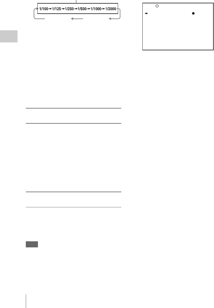
Setting the Electronic Shutter
62
Chapter 3 Adjustments and Settings for Shooting
repeat this until the desired mode or
speed appears.
When all modes and speeds are displayed,
the display changes in the following order.
If you have changed the configuration, only
the selected modes and speeds appear.
• When the unit is shipped from the factory, it is
configured to display all of the modes and
speeds in “Shutter modes” on page 60, except
SLS mode. You can change this configuration
by selecting only the required modes and
speeds on the SHT ENABLE page of the
OPERATION menu (see page 134).
• Shutter speeds in standard mode can also be
switched to angle display by using SHT DISP
MODE in the CAM CONFIG 2 page of the
MAINTENANCE menu (see page 154).
To set the shutter speed in ECS or SLS
mode
1Set the shutter speed mode to ECS or
SLS (see the previous item).
2Turn the MENU knob to select the
desired frequency or number of frames.
When the RM-B150 Remote Control Unit is
connected
You can set the shutter speed of ECS or SLS with
the rotary encoder of the RM-B150.
To change the range of choice of shutter
mode and speed settings
You can reduce the time required to select the
shutter mode and speed by narrowing the choice
of settings in advance. This can be done by using
the SHT ENABLE page of the OPERATION
menu.
Note
The settings selected on the SHT ENABLE page of the
OPERATION menu become invalid when the RM-B150
or another remote control unit is connected to the
camcorder.
1Display the SHT ENABLE page of the
OPERATION menu, and press the
MENU knob.
For details on menu operations, see “Basic
menu operations” on page 163.
2Turn the MENU knob to move b to the
shutter mode or shutter speed you want,
then press the MENU knob.
b on the left of the selected item changes to
z and z on the left of the setting changes to
?.
3Turn the MENU knob until “ON”
appears, then press the MENU knob.
z on the left of the selected item changes to
b and ? on the left of the setting changes to
z.
To set another mode or speed, return to step
2.
Note that only the shutter speeds set to “ON”
can be selected with the SHUTTER selector.
4To end the menu operation, set the
MENU ON/OFF switch to OFF or close
the cover of the menu operating section.
The menu disappears from the screen and the
display indicating the current status of the
camcorder appears along the top and bottom
of the screen.
ECS mode
Standard mode (with system frequency: 59.94i)
SLS mode
022 SHT ENABLE
SHUTTER ECS : ON
SHUTTER SLS : OFF
SHUTTER 1/100 : ON
SHUTTER 1/125 : ON
SHUTTER 1/250 : ON
SHUTTER 1/500 : ON
SHUTTER 1/1000 : ON
SHUTTER 1/2000 : ON
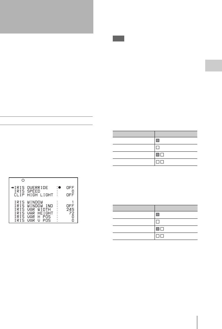
Changing the Reference Value for Automatic Iris Adjustment 63
Chapter 3 Adjustments and Settings for Shooting
The reference value for automatic iris adjustment
can be changed to aid the shooting of clear
pictures of back-lit subjects, or to prevent blown-
out highlights. The reference value for the lens
iris can be set within the following range with
respect to the standard value.
• 0.25 to 1 (increasing by increments of 0.25):
About 0.25 to 1 stop further open
• –0.25 to –1 (decreasing by increments of 0.25):
About 0.25 to 1 stop further close
Also you can set the area where light detection
occurs.
To change the reference value
(How to select an item in the menu screen: Turn
the MENU knob to move b to the desired item.)
1Display the AUTO IRIS page of the
OPERATION menu, and press the
MENU knob.
For details on menu operations, see “Basic
menu operations” on page 163.
2Check that the b mark is at the IRIS
OVERRIDE position, and then press
the MENU knob.
b on the left of the selected item changes to
z and z on the left of the setting changes to
?.
3Turn the MENU knob until “ON”
appears, then press the MENU knob.
z on the left of the selected item changes to
b and ? on the left of the setting changes to
z.
The IRIS OVERRIDE item is set to “ON”.
4Set the MENU ON/OFF switch to OFF.
The AUTO IRIS page disappears from the
screen.
5Turn the MENU knob to change the
reference value.
Note
Be sure to confirm that the current shutter mode is
not ECS.
The changed reference value is retained until
the power of the camcorder is turned off.
Even if the reference value is changed, it
reverts to the standard value every time the
power is turned on.
To make the iris more open
Turn the MENU knob counterclockwise as
seen from the front of the camera.
The iris stop indicators as shown in the
following table appear in the upper part to the
left of the F number in the iris indication.
To stop down the iris
Turn the MENU knob clockwise as seen
from the front of the camera.
The iris stop indicators as shown in the
following table appear in the lower part to the
left of the F number in the iris indication.
Changing the Reference
Value for Automatic Iris
Adjustment
016 AUTO IRIS
Iris stop Indicator
0.25
0.5
0.75
1
Iris stop Indicator
–0.25
–0.5
–0.75
–1
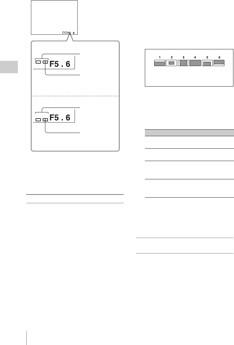
Changing the Reference Value for Automatic Iris Adjustment
64
Chapter 3 Adjustments and Settings for Shooting
When the RM-B150 Remote Control Unit is
connected
The IRIS control knob of the RM-B150 can be
used for lens iris setting. In this case, the indicator
is not displayed.
To set the automatic iris window
1Follow the procedure of steps 1 and 2
described in the previous item to
display the AUTO IRIS page.
2Turn the MENU knob to move b to
IRIS WINDOW IND, then press the
MENU knob.
b on the left of IRIS WINDOW IND.
changes to z and z on the left of the setting
changes to ?.
3Turn the MENU knob until “ON”
appears, then press the MENU knob.
z changes to b and ? changes to z
The currently selected auto iris window
appears on the screen.
If it is not necessary to display the auto iris
window on the screen, set to “OFF”.
4Turn the MENU knob to move b to
IRIS WINDOW, then press the MENU
knob.
b changes to z and z changes to ?.
5Turn the MENU knob until the desired
auto iris window appears, then press the
MENU knob.
z changes to b and ? changes to z.
If you select “VARIABLE”, the following
items become effective and you can set the
window of the desired size. Set each item to
the desired size.
6Set the MENU ON/OFF switch to OFF.
The menu disappears from the screen and the
display indicating the current status of the
camcorder appears along the top and bottom
of the screen.
To counter problems with very bright
highlights
If the subject is too bright, the iris may close too
much, leaving the overall image dark, or the
highlights may be blown out. In such cases,
setting the highlight clip function on reduces the
luminance range, avoiding problems from the
automatic iris correction.
In the AUTO IRIS page of the USER menu, set
the CLIP HIGH LIGHT item to “ON”.
Opening the lens iris
Iris opened by 1
stop (two
segments)
Iris opened by 0.5
stop (one segment)
Stopping down the lens iris
Iris stopped down
by 1 stop (two
segments)
Iris stopped down
by 0.5 stop (one
segment)
Item Setting
IRIS VAR WIDTH The width of the
window
IRIS VAR HEIGHT The height of the
window
IRIS VAR H POS. The position of the
window in the
horizontal direction
IRIS VAR V POS. The position of the
window in the vertical
direction.
The shaded parts indicate the
area where light detection
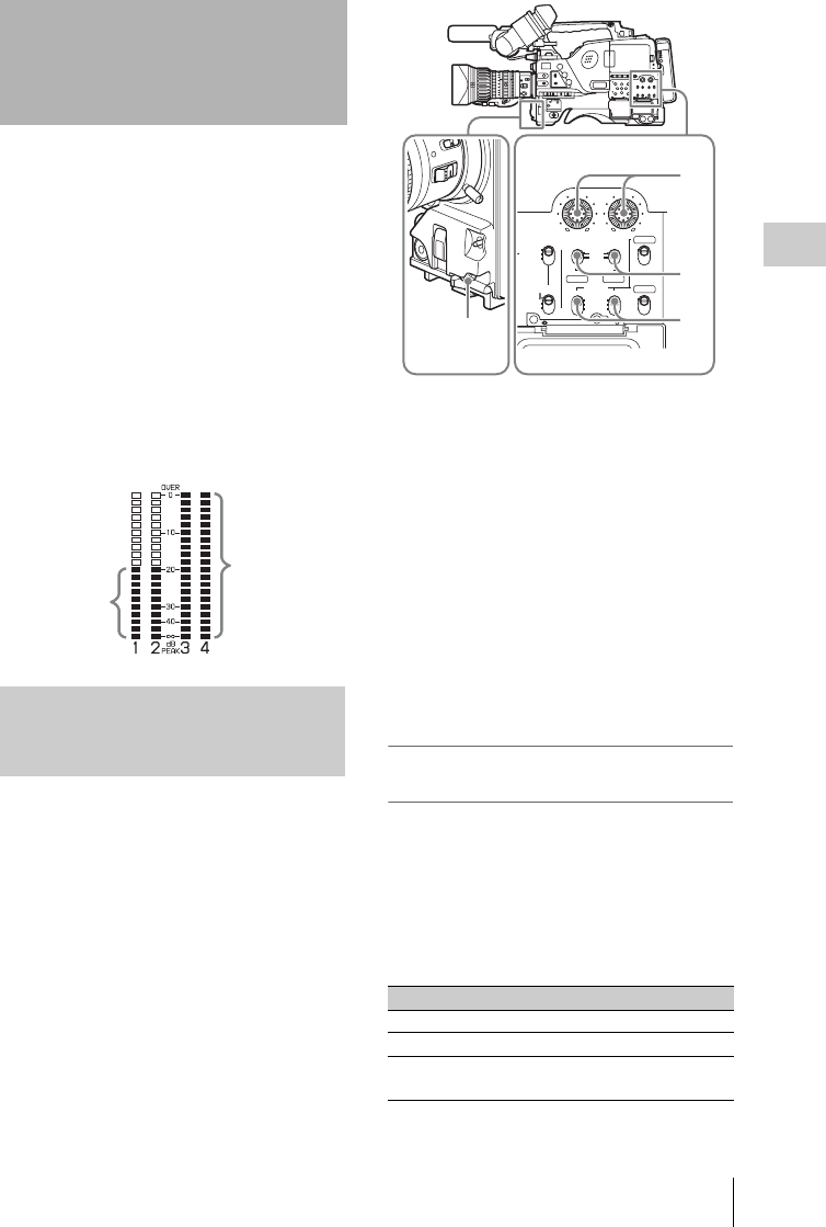
Adjusting the Audio Level 65
Chapter 3 Adjustments and Settings for Shooting
Setting the AUDIO SELECT CH-1/CH-2
switches to AUTO automatically adjusts the input
levels of the audio signal to be recorded in audio
channels 1 and 2. You can also adjust the audio
level manually.
For audio channels 3 and 4, menu settings allow
you to select automatic adjustment, manual
adjustment, or fixed.
Target audio level for automatic audio level
adjustment
Make adjustment using –20 dB as the target level.
If the audio level meter shows a maximum level
of 0 dB, then it indicates that the input audio level
is excessive.
With the XLR connection automatic detection
function being on, when a cable is connected to
the AUDIO IN CH1 or CH2 connector, the input
from these connectors is automatically selected
for audio recording. In this case, start the
operation from step 2.
You can turn on and off the XLR connection
automatic detection function on the AUDIO-1 page
of the MAINTENANCE menu.
1To adjust the signal input to the AUDIO
IN CH1 or AUDIO IN CH2 connector,
set the AUDIO IN CH-1 or AUDIO IN
CH-2 switch to REAR.
To adjust both input signals, set both
switches to REAR.
2Set the AUDIO SELECT switch(es)
corresponding to the channel(s) selected
in step 1 to MANUAL.
3With the LEVEL control(s) for the
channel(s) selected in step 1, adjust so
that the audio level meter shows up to
–20 dB for a normal input volume.
Correspondence between recording level
adjustments and audio level controls
On the AUDIO-3 page of the MAINTENANCE
menu, you can select which audio level control
controls the audio recording level of the input to
each of the AUDIO IN CH1/CH2 connectors. The
correspondences between the settings of the menu
items and the controls are as follows.
REAR1/WRR LEVEL: Audio recording level
of channel 1
Adjusting the Audio
Level
Manually adjusting the audio
levels of the audio inputs from the
AUDIO IN CH1/CH2 connectors
Target input
level
Excessive
input level
Setting Control
SIDE1 LEVEL (CH-1) control (on the left)
FRONT MIC LEVEL control
F+S1 LEVEL (CH-1) control linked with
MIC LEVEL control.
AUTO
FRONT
WIRELESS
REAR
CH-1
MANUAL
AUDIO SELECT
AUDIO IN
F
W
R
F
W
R
LEVEL
010010
CH-2
CH-3
CH-4
PRESET
F-RUN
REGEN
SET
CLOCK
R-RUN 2
3
1
MIC LEVEL
control
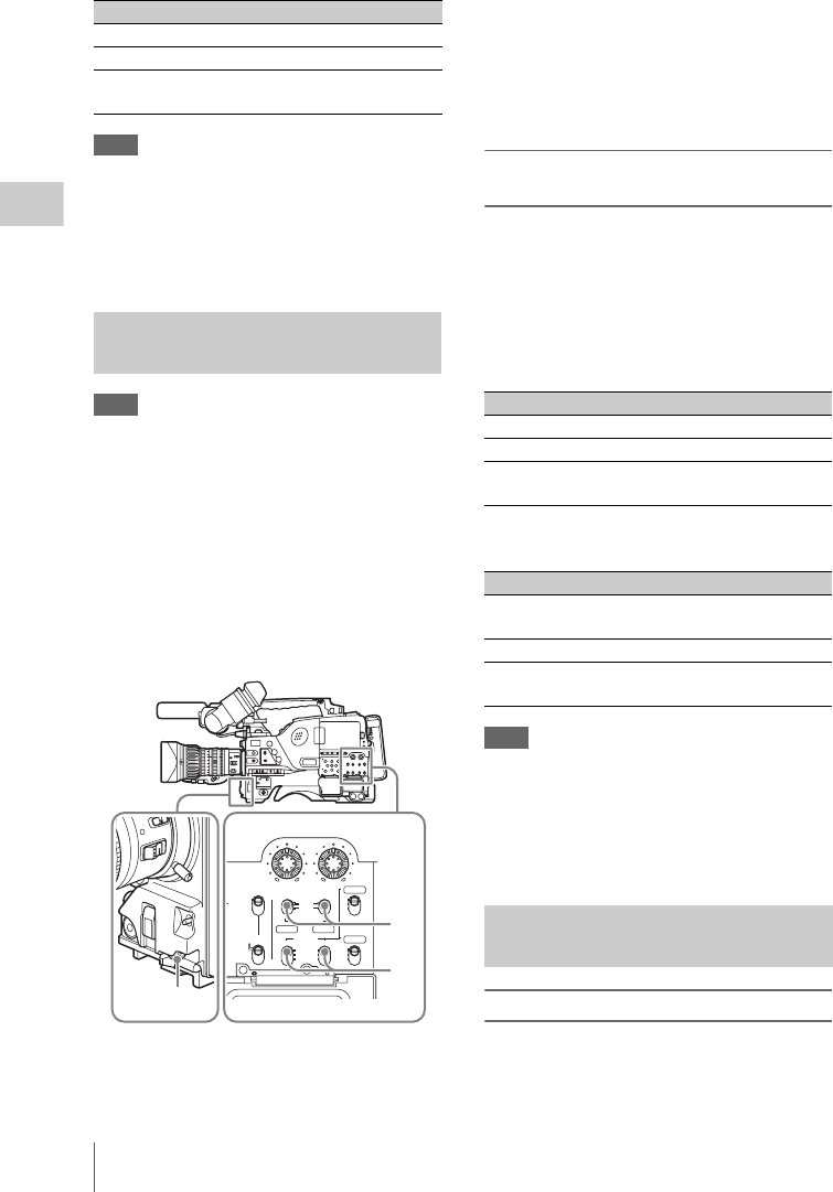
Adjusting the Audio Level
66
Chapter 3 Adjustments and Settings for Shooting
REAR2/WRR LEVEL: Audio recording level
of channel 2
Note
When you have operation of the LEVEL (CH-1/CH-2)
controls and MIC LEVEL control linked together, if the
MIC LEVEL control is set to 0, the audio signals on
channels 1 and 2 cannot be recorded. Check the position
of the MIC LEVEL control before adjusting the LEVEL
(CH-1/CH-2) controls.
Note
If the XLR connection automatic detection mode is on,
when the cables are connected to the AUDIO IN CH1/
CH2 connectors, the camcorder detects the connection to
the AUDIO IN CH1/CH2 connectors. Thus, the AUDIO
IN switches are internally reset to REAR and the audio
signals input to the AUDIO IN CH1/CH2 connectors are
automatically selected.
Before adjusting the audio level of the front microphone,
confirm that no cables are connected to the AUDIO IN
CH1/CH2 connectors. Alternatively, set the REAR XLR
AUTO item to “OFF” on the AUDIO-1 page of the
MAINTENANCE menu.
1Set either or both of the AUDIO IN
switch(es) to FRONT.
2Set the AUDIO SELECT switch(es) for
the desired channel(s) selected in step 1
to MANUAL.
3Turn the MIC LEVEL control, and
adjust so that the audio level meter
shows up to –20 dB for a normal input
volume.
Correspondence between recording level
adjustments and audio level controls
On the AUDIO-3 page of the MAINTENANCE
menu, you can select which audio level control
controls the audio recording level of the front
microphone input. The correspondences between
the settings of the menu items and the controls are
as follows.
MIC CH1 LEVEL: Audio recording level of
channel 1
MIC CH2 LEVEL: Audio recording level of
channel 2
Note
When you have operation of the MIC LEVEL control
and LEVEL (CH-1/CH-2) controls linked together, if the
LEVEL (CH-1/CH-2) controls are set to 0, the audio
signals on channels 1 and 2 cannot be recorded. Check
the position of the LEVEL (CH-1/CH-2) controls before
adjusting the MIC LEVEL control.
Selecting the recorded audio
You can select the audio recorded on audio
channels 3 and 4 with the AUDIO IN CH-3/CH-
4 switches, or you can have the selection made
automatically, as follows.
Setting Control
SIDE2 LEVEL (CH-2) control (on the right)
FRONT MIC LEVEL control
F+S2 LEVEL (CH-2) control linked with
MIC LEVEL control.
Manually adjusting the audio
level of the MIC IN connector
AUTO
FRONT
WIRELESS
REAR
CH-1
MANUAL
AUDIO SELECT
AUDIO IN
F
W
R
F
W
R
LEVEL
010010
CH-2
CH-3
CH-4
PRESET
F-RUN
REGEN
SET
CLOCK
R-RUN
2
31
Setting Control
SIDE1 LEVEL (CH-1) control (on the left)
FRONT MIC LEVEL control
F+S1 LEVEL (CH-1) control linked with
MIC LEVEL control.
Setting Control
SIDE2 LEVEL (CH-2) control (on the
right)
FRONT MIC LEVEL control
F+S2 LEVEL (CH-2) control linked with
MIC LEVEL control.
Recording audio on channels 3
and 4
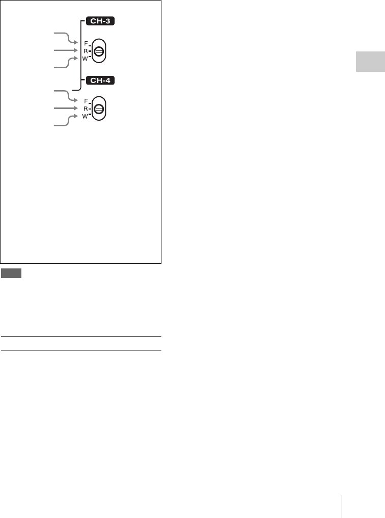
Adjusting the Audio Level 67
Chapter 3 Adjustments and Settings for Shooting
To automatically select the same audio as on
channels 1 and 2
On the AUDIO-1 page of the MAINTENANCE
menu, set the AUDIO CH3/4 MODE item to “CH
1/2”.
Note
When the LINE/AES/EBU/MIC switch is set to LINE or
MIC, the audio signals recorded on audio channels 3 and
4 are not affected by the XLR automatic detection
function. They are determined by the settings of the
AUDIO IN CH-3 and CH-4 switches.
Adjusting the audio recording levels
To adjust automatically
Set AU CH34 AGC MODE on the AUDIO-2 page of the
MAINTENANCE menu to STREO or MONO.
To adjust manually
1Set AU CH34 AGC MODE on the
AUDIO-2 page of the MAINTENANCE
menu to OFF.
2Set AUDIO CH3 LEVEL (for audio
channel 3) and AUDIO CH4 LEVEL
(for audio channel 4) on the AUDIO-3
page of the MAINTENANCE menu to
FRONT.
The levels of audio channels 3 and 4 can now
be adjusted with the MIC LEVEL control.
To set to a fixed value
In step 2 of the previous procedure “To adjust
manually”, set the menu items to FIX.
1
2
3
4
5
6
CH-3 switch
1F: The audio signal from the front
microphone is recorded.
2R: The audio signal input to the AUDIO IN
CH1 connector is recorded.
3W: The audio signal of the wireless
microphone is recorded.
CH-4 switch
4F: Same as with the CH3 switch.
5R: The audio signal input to the AUDIO IN
CH2 connector is recorded.
6W: Same as with the CH3 switch.
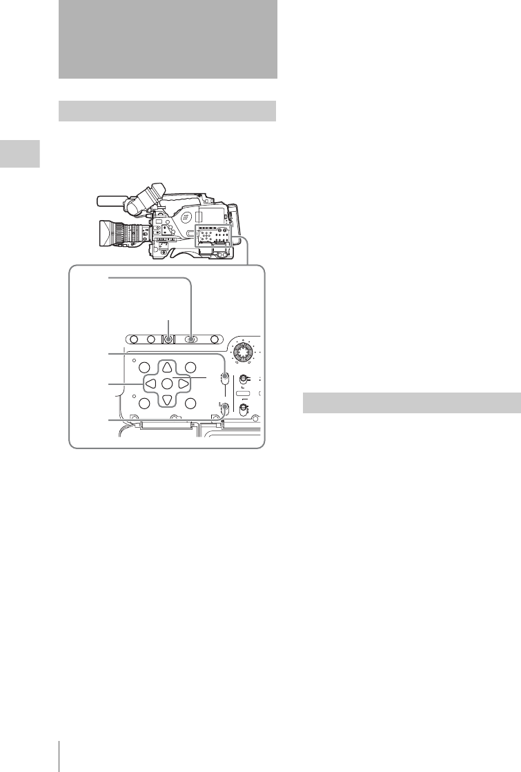
Setting the Time Data
68
Chapter 3 Adjustments and Settings for Shooting
The timecode setting range is from 00 : 00 : 00 :
00 to 23 : 59 : 59 : 29 (hours : minutes : seconds :
frames) for the PDW-700.
1Set the DISPLAY switch to TC.
2Set the PRESET/REGEN/CLOCK
switch to PRESET.
3Set the F-RUN/SET/R-RUN switch to
SET.
The first (leftmost) digit of timecode flashes.
4Use the up and down arrow buttons to
change values, and use the left and right
arrow buttons to move the flashing
digit. Repeat until all digits are set.
To reset the timecode value to 00 00 00 00
Press the RESET/RETURN button.
5Set the F-RUN/SET/R-RUN switch to
F-RUN or R-RUN.
F-RUN: Free run. The timecode generator
keeps running.
R-RUN: Recording run. The timecode
generator runs only while recording.
To set the drop frame mode/non-drop frame
mode
You can select the drop frame (DF) mode or non-
drop frame (NDF) mode on the TIMECODE page
of the MAINTENANCE menu.
To make the timecode consecutive
When the F-RUN/SET/R-RUN switch is set to
R-RUN, recording a number of scenes on the disc
normally produces consecutive timecode.
However, once you remove the disc and record on
another disc, the timecode will no longer be
consecutive when you use the original disc again
for recording. In this case, to make the timecode
consecutive, set the PRESET/REGEN/CLOCK
switch to REGEN.
Saving the real Time in the Timecode
Setting the PRESET/REGEN/CLOCK switch to
CLOCK saves the real time in the timecode.
When it is necessary to set the actual time, use the
TIME/DATE page of the DIAGNOSIS menu.
For details, see “Setting the Date/Time of the
Internal Clock” on page 41.
By setting the user bits (up to 8 hexadecimal
digits), you can record user information such as
the date, time, or scene number on the timecode
track.
Setting the Time Data
Setting the timecode
AUTO
FRONT
WIRELES
S
THUMBNAIL
SET
S.SEL
SHIFT
ESSENCE
MARK
CLIP MENU
SUB CLIP
REAR
CH-1
MANUAL
AUDIO SEL
E
AUDIO I
N
LEV
E
010
PRESET
F-RUN
REGEN
SET
CLOCK
R-RUN
BRIGHTDISPLAYRESETHOLDDISP SEL
COUNTER RC U-BITEXPAND CHAPTER
1
3,5
4
2
RESET/RETURN
button
Setting the user bits
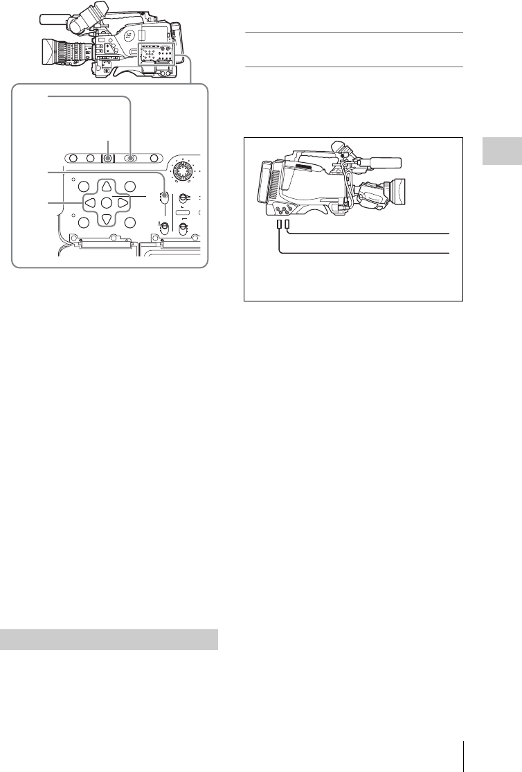
Setting the Time Data 69
Chapter 3 Adjustments and Settings for Shooting
1Set the DISPLAY switch to U-BIT.
2Set the F-RUN/SET/R-RUN switch to
SET.
The first (leftmost) digit flashes.
3Use the up and down arrow buttons to
change values, and use the left and right
arrow buttons to move the flashing
digit. Repeat until all digits are set.
To reset the user bit data to 00 00 00 00
Press the RESET/RETURN button.
4Set the F-RUN/SET/R-RUN switch to
F-RUN or R-RUN, corresponding to the
desired operating mode for the
timecode generator.
The set user bit data will be recorded for both
LTC and VITC.
To store the user bit setting in memory
The user bit setting (apart from the real time) is
automatically retained in memory even when the
power is turned off.
You can synchronize the internal timecode
generator of this camcorder with an external
generator for the regeneration of an external
timecode. You can also synchronize the timecode
generators of other camcorders/VTRs with the
internal generator of this camcorder.
Connections for timecode
synchronization
Connect both the reference video signal and the
external timecode as illustrated below.
Example 1: Synchronizing with an external
timecode
a) Set GENLOCK to ON on the GENLOCK page of the
MAINTENANCE menu, if GENLOCK is set to OFF.
Synchronizing the timecode
AUTO
FRONT
WIRELES
S
THUMBNAIL
SET
S.SEL
SHIFT
ESSENCE
MARK
CLIP MENU
SUB CLIP
REAR
CH-1
MANUAL
AUDIO SEL
E
AUDIO I
N
LEV
E
010
PRESET
F-RUN
REGEN
SET
CLOCK
R-RUN
BRIGHTDISPLAYRESETHOLDDISP SEL
COUNTER RC U-BITEXPAND CHAPTER
1
3
2,4
RESET/RETURN button
1GENLOCK IN a)
2TC IN
2
1
Reference video signal
External timecode
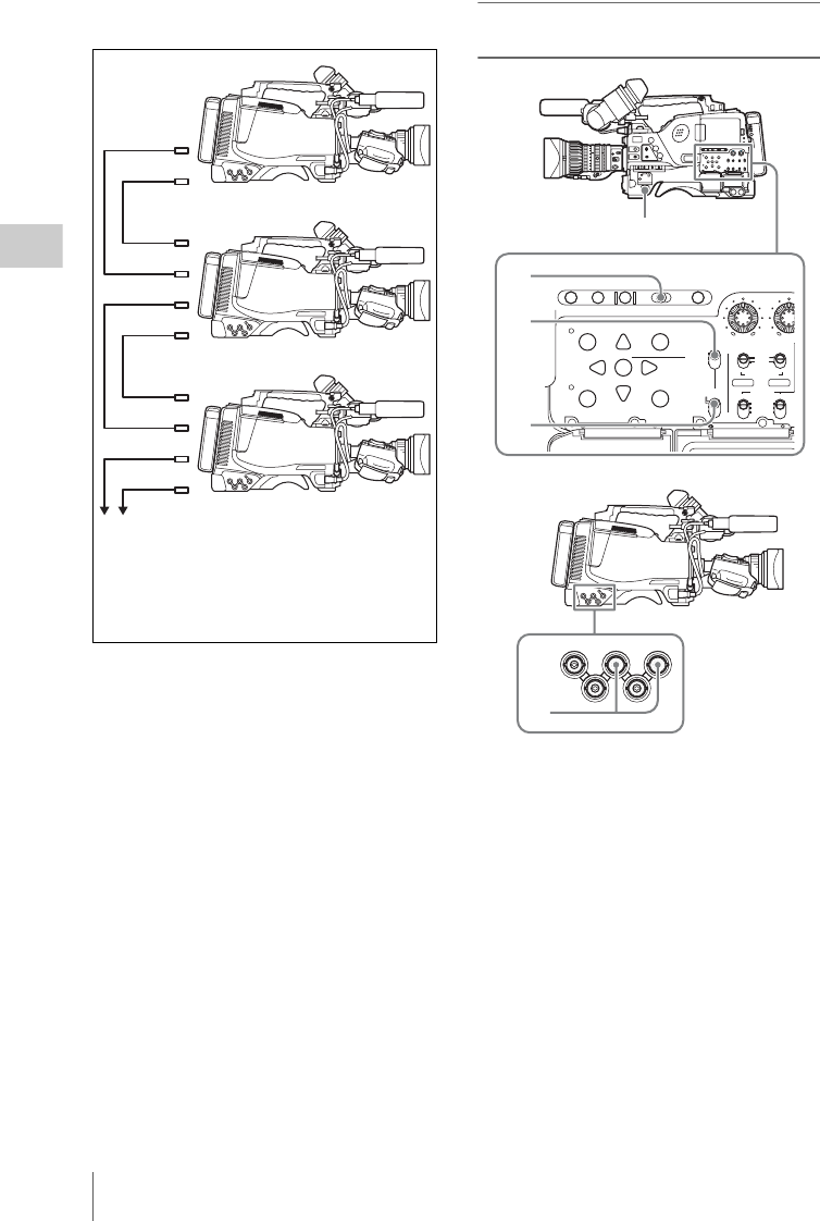
Setting the Time Data
70
Chapter 3 Adjustments and Settings for Shooting
Example 2: Interconnecting a number of
camcorders or timecode synchronization
a) Set GENLOCK to ON on the GENLOCK page of the
MAINTENANCE menu, if GENLOCK is set to OFF.
To lock the timecode to an external
source
1Turn on the POWER switch.
2Set the PRESET/REGEN/CLOCK
switch to PRESET.
3Set the F-RUN/SET/R-RUN switch to
F-RUN.
4Set the DISPLAY switch to TC.
5Supply a timecode signal and a
reference video signal complying with
the SMPTE standard and in proper
phase relationship, to the TC IN
connector and to the GENLOCK IN
connector, respectively.
1
2
3
4
1
2
3
4
1
2
1TEST OUT
2TC OUT
3TC IN
4GENLOCK IN a)
To another camcorder to be synchronized
Reference camcorder
AUTO
FRONT
WIRELESS
THUMBNAIL
SET
S.SEL
SHIFT
ESSENCE
MARK
CLIP MENU
SUB CLIP
REAR
CH-1
MANUAL
AUDIO SELECT
AUDIO IN
LEVEL
0100
CH-2
PRESET
F-RUN
REGEN
SET
CLOCK
R-RUN
BRIGHTDISPLAYRESETHOLDDISP SEL
COUNTER RC U-BITEXPAND CHAPTER
3
1
2
4
GENLOCK
IN
TC
OUT
TEST
OUT
TC IN
SDI IN
(OPTION)
5

Setting the Time Data 71
Chapter 3 Adjustments and Settings for Shooting
This operation synchronizes the internal
timecode generator with the external
timecode. After about 10 seconds, you can
disconnect the external timecode without
losing the synchronization. However, there
will be noise on the recorded image if you
connect or disconnect the timecode signal
during recording.
Notes
• When you finish the above procedure, the internal
timecode is immediately synchronized with the
external timecode and the counter display will show
the value of the external timecode. However, wait for
a few seconds until the sync generator stabilizes before
recording.
• If the frequency of the reference video signal is not the
same as the system frequency of the camcorder, the
camera cannot be correctly genlocked. In such a case,
the internal timecode is not correctly synchronized
with the external timecode.
• When the GENLOCK ON/OFF item is set to OFF on
the GENLOCK page of the MAINTENANCE menu,
the timecode cannot be synchronized with the
reference video signal. In this case, set the GENLOCK
item to ON on the GENLOCK page of the
MAINTENANCE menu.
User bit settings during timecode
synchronization
When the timecode is synchronized, only the time
data is synchronized with the external timecode
value. Therefore, each camcorder can have its
own user bit settings.
You can lock the users bits of this camcorder to
the user bits of external timecode by setting EXT-
LK UBIT in the TIMECODE page of the
MAINTENANCE menu to EXT.
To release the timecode synchronization
First disconnect the external timecode, then set
the F-RUN/SET/R-RUN switch to R-RUN.
To change the power supply from the battery
pack to an external power supply during
timecode synchronization
To maintain a continuous power supply, connect
the external power supply to the DC IN connector
before removing the battery pack. You may lose
timecode synchronization if you remove the
battery pack first.
Camera synchronization during timecode
synchronization
During timecode synchronization, the camera is
genlocked to the reference video signal input
from the GENLOCK IN connector.
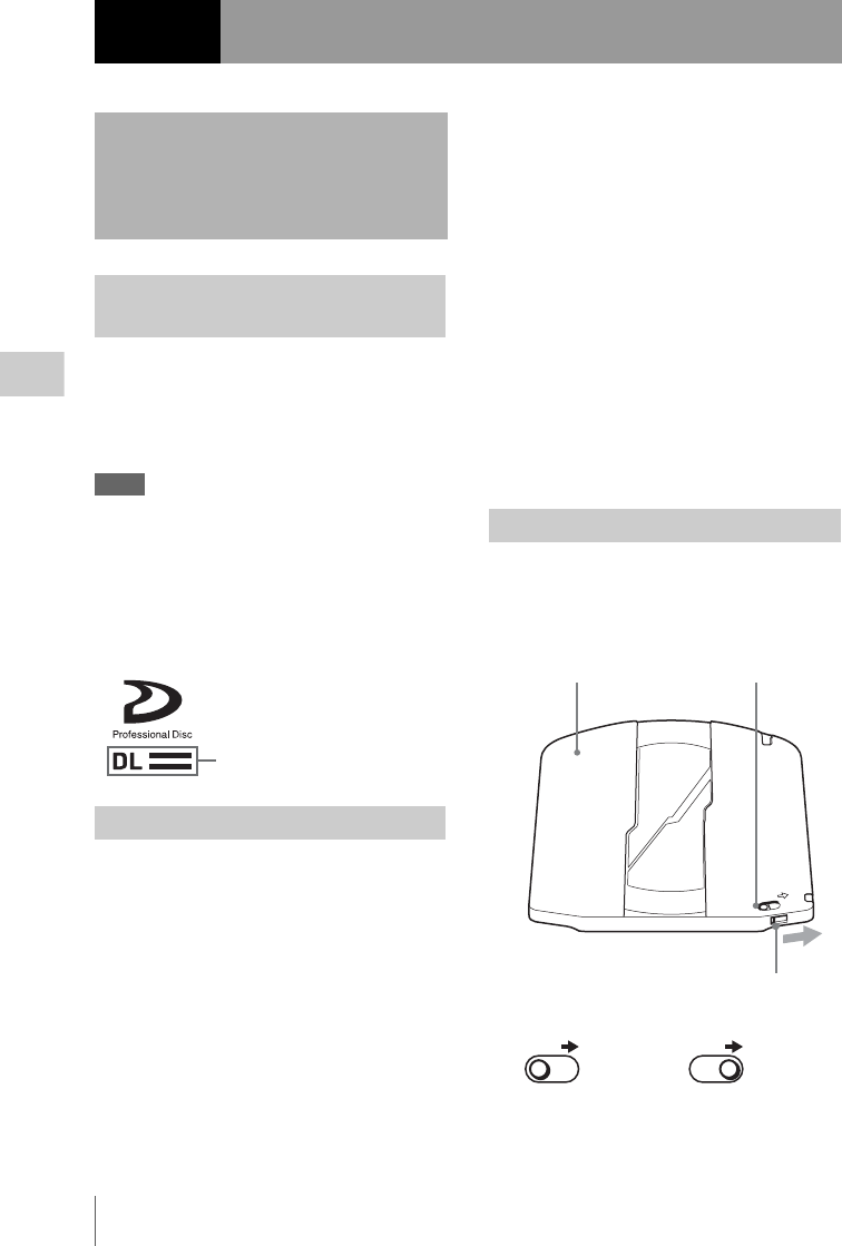
Handling Discs
72
Chapter 4 Shooting
The following Professional Discs 1) can be used
for recording and playback on this unit:
• PFD23A (capacity 23.3 GB)
• PFD50DLA (capacity 50.0 GB)
1) Professional Disc is a trademark of Sony Corporation.
Notes
• It is not possible to use the following discs for
recording or playback on this unit:
-Blu-ray Disc
- Professional Disc for Data
• PFD50DLA discs can be used only by XDCAM
devices with the DL mark (see the following
illustration). They cannot be used by XDCAM devices
without this mark.
Handling
The Professional Disc is housed in a cartridge,
and is designed to allow handling free of risk
from dust or fingerprints. However, if the
cartridge is subjected to a severe shock, for
example by dropping it, this can result in damage
or scratching of the disc. If the disc is scratched,
it may be impossible to record video/audio, or to
play back the content recorded on the disc. The
discs should be handled and stored carefully.
• Do not touch the surface of the disc itself within
the cartridge.
• Deliberately opening the shutter may cause
damage.
• Do not disassemble the cartridge.
• The supplied adhesive labels are recommended
for indexing discs. Apply the label in the correct
position.
Storage
• Do not store discs where they may be subjected
to direct sunlight, or in other places where the
temperature or humidity is high.
• Do not leave cartridges where dust may be able
to gain ingress.
• Store cartridges in their cases.
Care of the discs
• Remove dust and dirt on the outside of a
cartridge using a soft dry cloth.
• If condensation forms, allow ample time to dry
before use.
To protect the content recorded on the disc from
accidental erasure, move the Write Inhibit tab on
the lower surface of the disc in the direction of the
arrow, as shown in the following figure.
Chapter4Shooting
Handling Discs
Discs used for recording and
playback
Notes on handling
DL mark
Write-protecting discs
SAVE
SAVE SAVE
Lower surface of the disc Write Inhibit tab
Slide in the direction of the arrow
Recording enabled Recording disabled
Write Inhibit tab settings
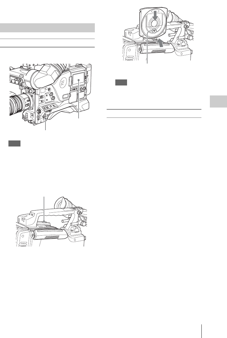
Handling Discs 73
Chapter 4 Shooting
You can also write protect-individual clips. For
details, see “Locking (write-protecting) clips” on
page 111.
To load a disc
1Turn on the POWER switch.
Note
If there is condensation inside the VDR section, the
message “HUMID” appears in the status display on
the color LCD . If this happens, wait until the
indicator goes off before going on to step 2.
2Press the EJECT button.
This opens the lid of the disc compartment.
31 Insert the disc in the V direction, and
2 close the disc compartment lid
manually.
The disc is loaded.
Note
To insert the disc correctly, make sure that the
camcorder is in the upright position (the grip
upside, the bottom downside).
To unload a disc
With the power supply on, press the EJECT
button to open the disc compartment lid and eject
the disc, then remove the disc. If you are not
going to insert another disc, close the disc
compartment lid.
To unload a disc when the power supply is off
If the battery is exhausted, it is not possible to
remove the disc by pressing the EJECT button. In
such cases, use the following emergency
procedure to remove the disc manually.
1Turn off the POWER switch.
2Carry out the operation shown in the
following figure.
1Open this rubber cover.
2Using a screwdriver or similar
implement, slide the black metal plate
visible inside, in the direction of the
rear of the camcorder.
The disc compartment lid opens. A red
Phillips screw is visible inside the
rubber cap.
3Use a Phillips screwdriver to turn the
screw counterclockwise (the direction
shown on the rubber cap).
This ejects the disc.
4Close the rubber cover firmly.
Loading and unloading a disc
POWER switch
LCD monitor
EJECT button
1
2
V indication on the outside
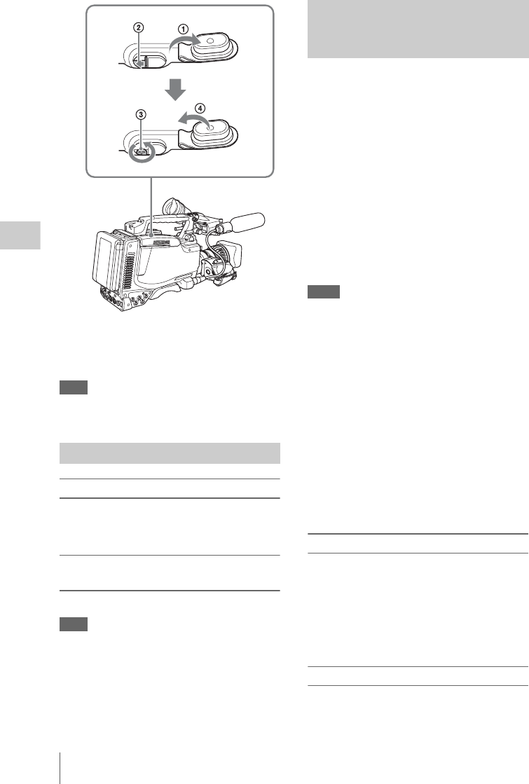
Handling Discs
74
Chapter 4 Shooting
You need not return the screw to its original
position after taking out the disc. Turning on the
power makes the disc compartment mechanism
operable again.
Note
Do not touch the disc or try to forcibly remove it until it
has been completely ejected.
When using a new disc
An unused disc requires no formatting operation.
The disc is automatically formatted so that it is
ready to use when loaded into this unit.
To format a disc on which material is
recorded
See page 123 for details of formatting a disc.
Note
When a recorded disc is formatted, all the data on the
disc is erased. (Even locked clips (see page 111) are also
erased.)
Recording processing does not end normally if,
for example, the battery pack is removed during
recording, or if the power cord is disconnected
during recording. Because the file system is not
updated, video and audio data recorded in real
time is not recognized as files and clip contents
recorded up to that point are lost.
However, this unit has a salvage function which
can hold losses to the minimum by reconstructing
clips on such discs.
Note that no recorded clip contents are lost when
the POWER switch is set to OFF and when
battery exhaustion is detected, because the unit
does not become powered off until after the end
of recording processing.
Notes
• Do not disconnect the battery pack or power cord until
recording processing has finished and the ACCESS
indicator has gone out.
• This function salvages as much recorded material as
possible after an unforeseen accident, but 100%
restoration cannot be guaranteed.
• Even when this function is used, it is not possible to
recover data from immediately before the interruption
of recording. The amount of data lost is as follows.
-Quick salvage: From 2 to 4 seconds of data before
the interruption of recording.
-Full salvage: From 4 to 6 seconds of data before the
interruption of recording.
(More data may be lost when the unit is subject to
vibrations, when you switch frequently between
recording and paused, and when you use functions
such as Picture Cash.)
Quick salvage
When the unit is powered on again after a
recording interruption due to a power
interruption, with the disc still loaded in the unit,
clips are reconstructed on the basis of backup data
stored in nonvolatile memory and markers
recorded on the disc. Processing time is about 5
seconds.
Full salvage
When recording on an XDCAM device is
interrupted because of a power interruption, and a
disc is manually ejected from that device with the
Formatting a disc
Handling of discs when recording
does not end normally (salvage
function)

Handling Discs 75
Chapter 4 Shooting
power off, clips are reconstructed on the basis of
markers recorded on the disc when the disc is
loaded in this unit. Therefore, processing takes
longer than for a quick salvage (about 30 seconds,
although it depends on the state of the disc).
Proceed as follows to perform a full salvage.
1Insert the disc on which recording did
not end normally.
The following salvage message appears.
2Turn the MENU knob to move b to
“YES”, and press the MENU knob.
Salvage processing starts, and the message
“EXECUTING” appears.
A results message appears when the
processing finishes.
• If the salvage succeeded, the message
“COMPLETED” appears.
• If the salvage failed, the message
“INCOMPLETED”appears. Clips for
which recording did not end normally are
lost.
To exit without salvaging
Select NO in step 1 to exit without performing
salvage processing.
However, the status of the disc does not change.
Salvage is still required to recover the clips for
which recording did not end normally. The
salvage message will appear again when that disc
is inserted again, or when the camcorder is
powered on again.
Notes
• If salvage processing is not done, sections
which were recorded normally can be played
back, but no new recording can be done on the
disc.
• Full salvage of discs recorded by this camcorder
can be performed with the PDW-HD1500 or
PDW-700. Full salvage cannot be performed
with any other XDCAM device. The following
message may appear when you insert a disc that
was not recorded normally. The “XXXX” in the
message is a code for XDCAM devices that can
salvage the disc. Refer to the table below and
use one of the indicated devices to salvage the
disc.
a) Does not appear on this unit.
To cancel the message and return to normal
operation, exchange the disc for a usable disc
and flick the CANCEL/PRST/ESCAPE switch
to the ESCAPE side, or press the MENU knob.
SALVAGE
TO RECORD ON THE
DISC, IT IS NECESSARY
TO EXECUTE SALVAGE.
SALVAGE OK?
YES NO
Code (XXXX) Model name
0002 PDW-1500/530/510/R1
PDW-F70/F350/F330
0200 PDW-F75/F355/F335
0300 a) PDW-HD1500/700
SALVAGE
DISC CANNOT BE
RECORDED.
FORMAT DISC OR CONTACT
SERVICE TO RUN CLIP
SALVAGE PROGRAM.
(XXXX)
PUSH ESCAPE SWITCH
OR ROTARY ENCODER.
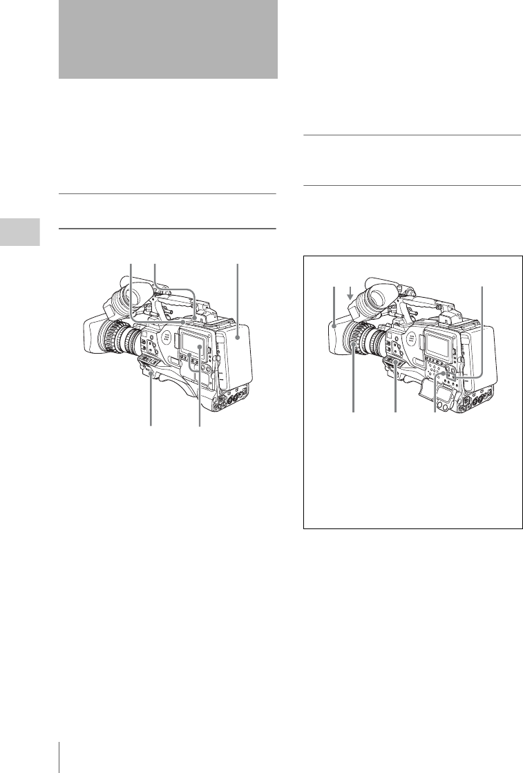
Basic Procedure for Shooting
76
Chapter 4 Shooting
This section describes the basic procedures for
shooting and recording.
Before a shooting session, ensure that the
camcorder is functioning properly.
For details, see “Testing the Camcorder Before
Shooting” on page 209.
Basic procedure for shooting: from power
supply to disc loading
1Attach a fully charged battery pack.
For details, see “Preparing a Power Supply” on
page 35.
2Set the POWER switch to ON.
3Press the DISP SEL/EXPAND button to
switch the LCD monitor to status
display, and check that the following
conditions are met.
• The HUMID indicator is not showing.
If it is, wait until it disappears.
• The battery status indicator shows at least
five segments (x).
If it does not, replace the battery pack with
a fully charged one.
4Check that there are no obstructions
such as cables near the disc
compartment lid. Then press the
EJECT button to open the disc
compartment lid.
5After checking that the disc is not write-
protected (see page 72), load it and close
the disc compartment lid.
Basic procedure for shooting: from
adjusting the black balance and white
balance to stopping recording
Switch settings
After turning on the power and loading a disc, set
the switches and selectors as shown below and
begin operation.
Basic Procedure for
Shooting
2
45 1
3
162
345
1DISPLAY: ON
2Iris: Automatic
3Zoom: Automatic
4OUTPUT/DCC: CAM, DCC: ON
5F-RUN/SET/R-RUN: F-RUN or R-RUN
(set as needed)
6AUDIO SELECT CH-1/CH-2: AUTO
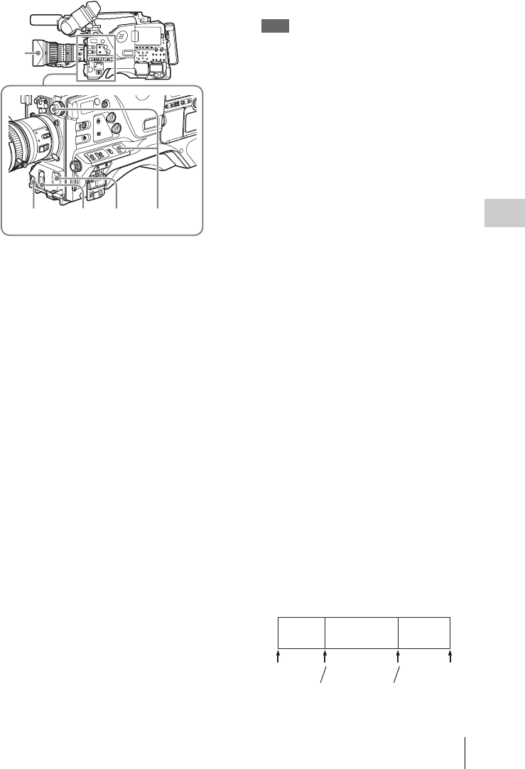
Basic Procedure for Shooting 77
Chapter 4 Shooting
Shooting
1Flick the AUTO W/B BAL switch to
BLK to adjust the black balance.
For details of black balance adjustment, see
page 55.
2Select the CC filter and ND filter to
match the lighting conditions, and
adjust the white balance.
For details, see “Adjusting the white balance”
on page 56.
3Aim the camera at the subject and
adjust the focus and zoom.
4If necessary, set the electronic shutter
for an appropriate mode and speed.
For details, see “Setting the Electronic Shutter”
on page 60.
5To start recording, press the REC
START button or the VTR button on
the lens.
If the recording start/stop function is
assigned to one of the ASSIGN 1/3/4
switches, COLOR TEMP. button, or RET
button on the lens, you can also use this
switch.
On how to assign functions to the ASSIGN
switches, see page 178.
During recording, the REC indicator lights in
the viewfinder. Perform zooming and focus
control, if necessary.
Note
During recording (while the ACCESS indicator is
lit) do not remove the battery pack. If you do, the
internal processing for recording may not finish
properly, which may cause the last few seconds of
recording to be lost.
For details, see “Handling of discs when
recording does not end normally (salvage
function)” on page 74.
6To stop recording, press the REC
START button or the VTR button on
the lens again.
The REC indicator in the viewfinder goes
off.
The material recorded from step 5 to step 6 is
saved as a single clip.
To check the last two seconds of the
recording (recording review)
If you press the RET button on the lens while
recording is paused, the last two seconds of
the recording is played back. If you hold
down the RET button, a low-speed reverse
search begins at a position two seconds
before the recording end position. When you
release the RET button, the reverse search
stops and playback in the forward direction
begins. After playback, the camcorder is
ready to start recording again.
By assigning the the same function as that of
the RET button on the lens to the ASSIGN 1/
3/4 switch or COLOR TEMP. button, you
can use the switch in the same way as the lens
RET button.
On how to assign functions to the ASSIGN
switches, see page 178.
7Repeat steps 5 and 6 as required for
shooting.
Each time you repeat steps 5 and 6, successive
clips are recorded on the disc.
5,6 4
3
12
REC
START
REC
STOP
REC
START
REC
STOP
REC
START
REC
STOP
Clip 1 Clip 2 Clip 3

Basic Procedure for Shooting
78
Chapter 4 Shooting
Notes
• It is not possible to record a clip shorter than 2 seconds.
If you stop recording within 2 seconds of starting, this
results in a 2-second clip.
If you stop recording and restart within 2 seconds of
the original start, this creates a single continuous clip
from the original start time.
• The maximum number of clips that can be recorded on
a single disc is 300. If an attempt is made to record
more than 300 clips, the error message “MAX # Clips”
appears, even if there is free capacity on the disc.
Playback control buttons
During recording, the playback control buttons
(EJECT, F REV, F FWD, NEXT, PREV, PLAY/
PAUSE, STOP) have no effect.
Normal playback
By pressing the PLAY/PAUSE button, you can
review any length of recording on the viewfinder
screen in black and white or in color on the LCD
monitor. There are two other ways to review the
recording.
Recording review: You can view the last two
seconds of the recording on the viewfinder
screen in black and white or in color on the
LCD monitor.
Viewing color playback on a video monitor:
You can view the recording in color on a
color video monitor without the need for any
external adaptor.
You can also view palyback video during a fast
forward or reverse search.
For details about the switches and controls used to
select the audio output signal and to adjust the audio
level, see page 18 and page 26.
To freeze a picture during playback
The following operation can also be done from
the RM-B150/B750 Remote Control Unit.
1Press the PLAY/PAUSE button to start
playback.
2Press the PLAY/PAUSE button again at
the instant when you want to freeze the
picture.
The playback pauses and a frozen picture
appears.
The timecode of the frozen frame is
displayed in the counter display and the
PLAY/PAUSE indicator now flashes (one
flash/second).
To restart playback
Press the PLAY/PAUSE button once again.
To display camera video in the
viewfinder during playback (Live & Play
function)
During playback, the viewfinder normally
displays the playback video. But you can enable
this function to view live camera video instead.
This is a convenient way to frame the next shot
and adjust the focus and exposure while viewing
recorded video on the LCD monitor or an external
monitor.
(How to select an item in the menu screen: Turn
the MENU knob to move the b mark to the
desired item.)
1Display the OUTPUT 2 page of the
OPERATION menu.
For details on menu operations, see “Basic
menu operations” on page 163.
2Select LIVE & PLAY, and then turn the
MENU knob to display “ON”.
The camera video appears in the viewfinder,
even during playback.
You can still check the playback video on the
LCD monitor. Playback signals are output
from the video output connectors.
Disc playback start position
Although this unit uses optical discs, it is
designed to offer the most convenient features of
tape playback by VTRs. One of these is the
playback start position, which works in the same
way as with tape, as described below.
After playback stop
The unit stops at the position where the STOP
button was pressed.
Press the PLAY/PAUSE button to resume
playback at the stop position.
After recording
The unit stops at the position where recording
ended.
Playing back the recorded clip

Basic Procedure for Shooting 79
Chapter 4 Shooting
To play back a clip, press the PREV button to
move to the start frame of any clip, or press the
F REV button to move to any position.
After disc insertion
The unit stops at the position of the disc when it
was most recently ejected.
Press the PLAY/PAUSE button to resume
playback at the most recent position.
The playback position is saved to the disc when
the disc is ejected, which allows playback to start
at that position whenever it is loaded into any
XDCAM player.
Note
The playback position is not recorded to the disc if the
disc is write-protected.
Deteriorating playback conditions
Deteriorating playback may be due to the
following causes.
• Scratches and dust on the disc surface
This includes fingerprints, dust from the air, tar
from cigarette smoke, and so on.
Scratches and soiling which occur before
recording are not a problem because they are
registered in advance as defects, and recording
avoids them. However, scratches and soiling
which occur after recording can lead to
deteriorating playback conditions.
• Aging of disc recording layers
Over several decades, the recording layers of
optical discs can age and cause deteriorating
playback conditions.
• Deteriorating laser diodes performance
The performance of the laser diodes used in
optical heads can worsen with age, leading to
deteriorating playback conditions.
Refer to the Maintenance Manual for an
approximate guide to when it is time to replace
optical heads.
To prevent playback conditions from
deteriorating
Pay attention to the following points when
handling discs.
• Do not open disc cartridges and touch discs
directly with your hands.
• Do not store for long periods in locations which
are dusty or exposed to air circulated by fans.
• Do not store for long periods under high
temperatures or in locations exposed to direct
sunlight.
If playback conditions have deteriorated
Read errors occur when playback conditions
continue to deteriorate.
When a read error occurs, the message “DISC
ERROR!” appears, the video freezes, and the
audio output is suppressed.
If this happens, check the following points.
Whether the disc displays the same playback
condition on other XDCAM devices: If so,
the surface of the disc may be dirty or
scratched, or the performance of the
recording layers on the disc may have
worsened due to age. Do not use discs with
these symptoms.
Whether every disc inserted into an XDCAM
device displays the same playback
conditions: If so, the performance of the
laser diodes may have deteriorated. Check
the total optical output time.
For details, see “Deleting clips” on page 112.
Deleting the recorded clip

Advanced Operations for Shooting
80
Chapter 4 Shooting
Shot marks and other essence marks can be
recorded on the disc.
Recording essence marks for scenes containing
important images and sounds enables quick
access to the marked points. This increases
editing efficiency.
To record a shot mark using the RET
button on the lens
To make it possible to record shot marks using the
RET button on the lens, carry out the following
procedure.
(How to select an item in the menu screen: Turn
the MENU knob to move b to the desired item.)
1Display the ESSENCE MARK page of
the MAINTENANCE menu.
For details on menu operations, see “Basic
menu operations” on page 163.
2Select the essence mark to be recorded,
and press the MENU knob to display
“ON”.
3Repeat the step 2, as necessary.
To record shot mark 1/2
When the camcorder is in recording or playback
mode, operate the lens RET button as follows.
Shot mark 1: Press the RET button once.
Shot mark 2: Press the RET button twice in rapid
succession.
“ShotMark1” or “ShotMark2” appears in the
viewfinder screen for about one second near the
timecode display.
If the SHOT MARK 1 or SHOT MARK 2
recording function has been assigned to one of the
ASSIGN 1/3/4 switches and COLOR TEMP.
button, you can also use that switch to record a
SHOT MARK 1 or SHOT MARK 2 essence
mark.
On how to assign functions to the ASSIGN switches,
see page 178.
You can set three types of clip flags (OK/NG/
KEEP) during recording, immediately after
recording, or during playback. Setting these flags
in each clip that you record makes it easy for
editors and other colleagues to find and select the
clips they need.
You can use switches on the unit to set these
flags. But before you can do so, you need to
assign the corresponding flag functions to the
ASSIGN 1/3/4 switches, the COLOR TEMP
button, or the RET button on the lens (see page
178).
To set a clip flag
During recording, immediately after recording, or
during playback (including search and still
picture playback), press the button to which the
flag function has been assigned. Press the button
once at the position where you want to set the
flag.
The specified flag is set, and “*** ClpFlg” (***:
OK, NG, or KEEP) appears near the timecode
display in the viewfinder for about three seconds.
To clear a clip flag
During recording or playback, press the button to
which the flag function has been assigned. Press
the button twice in rapid succession.
The flag is cleared, and “ClpFlg DEL.” appears
for about three seconds.
You can also set and clear clip flags from a GUI
screen. For details, see “Setting clip flags”
(page 111).
Advanced Operations for
Shooting
Recording essence marks
?M11 ESSENCE MARK TOP
RET SHOT MARK 1 : ON
RET SHOT MARK 2 : ON
INDEX PIC. POS : 0SEC
Setting clip flags with switches

Advanced Operations for Shooting 81
Chapter 4 Shooting
When you record a clip, you can specify which
frame to use as the clip thumbnail image (see
page 95).
(The factory default setting is to use the first
frame in the clip as the thumbnail.)
For example, if all clips have the same image in
their first frames, you can specify a frame a few
seconds after the start of the clip, so that all
thumbnails will not show the same image.
(How to select an item in the menu screen: Turn
the MENU knob to move b to the desired item.)
1Display the ESSENCE MARK page of
the MAINTENANCE menu, and press
the MENU knob.
For details on menu operations, see “Basic
menu operations” on page 163.
2Select INDEX PIC. POS, and press the
MENU knob.
3Turn the MENU knob to select the
desired time.
4Press the MENU knob.
The camcorder has a large capacity internal
memory, in which you can cache the last few
seconds (maximum 30 seconds) of captured
video and audio, so that recording starts from a
point just before you press the REC START
button or the VTR button on the lens.
Setting the Picture Cache mode/Picture
Cache time
To record in Picture Cache mode, you need to
turn on Picture Cache mode and set the picture
data storage time (Picture Cache time) using the
USER menu.
The Picture Cache time determines the number of
seconds recorded from the Picture Cache,
counting back from the time when you press the
REC START button or the VTR button on the
lens to start recording. However, the number of
seconds actually recorded from the Picture Cache
may be shorter immediately after the setting of
the VDR SAVE/STBY switch is changed, and in
the special situations explained in the following
notes.
Notes
• Storage of images to memory begins after you select
Picture Cache mode. If you begin recoding
immediately after selecting Picture Cache mode,
images from before the selection will not be recorded.
• During playback, recording review or GUI screen
operations, no data is saved to the Picture Cache
memory. Thus it is not possible to use this function to
rerecord the last few seconds of material from
playback or recording review.
To set the Picture Cache mode/Picture Cache
time
(How to select an item in the menu screen: Turn
the MENU knob to move b to the desired item.)
1Display the REC FUNCTION page of
the OPERATION menu.
For details on menu operations, see “Basic
menu operations” on page 163.
2Select CACHE REC, and turn the
MENU knob to display CACHE.
3Select CACHE REC TIME, and turn
the MENU knob to display the desired
Picture Cache time.
As you turn the MENU knob, the Picture
Cache time changes as follows: 0-2s y 2-4s
y 4-6s y 6-8s y 8-10s y 18-20s y
28-30s.
The Picture Cache mode settings once made
continue to be effective until changed.
You can assign the Picture Cache on/off function
to one of the ASSIGN 1/2/3/4 switches, COLOR
TEMP. button, and RET button on the lens.
For details, see “Assigning functions to ASSIGN
switches” on page 178.
Setting the thumbnail image at
recording time
Starting a shoot with a few
seconds of pre-stored picture data
(Picture Cache function)
CACHE/INTVAL REC: OFF
DISC EXCHG CACHE: OFF
005
REC FUNCTION TOP

Advanced Operations for Shooting
82
Chapter 4 Shooting
Notes
• You can do a menu operation to change the Picture
Cache time while the camcorder is in recording mode.
However, the new setting takes effect only after the
recording is finished.
• In Picture Cache mode, the internal timecode generator
operating mode is always F-RUN regardless of the
setting of the F-RUN/SET/R-RUN switch.
Camcorder operations in Picture Cache mode
The recording procedure in Picture Cache mode
is basically the same as that for normal recording.
However, note the following differences.
• When you record in Picture Cache mode, the
picture you are shooting now is recorded to disc
after the picture data stored in memory (equal to
the Picture Cache time) is recorded to disc. For
this reason, disc access may continue for a short
time after you press the REC START button to
stop recording. During this time, the playback
control buttons are disabled, as in recording
mode. Also, if you press the REC START
button or the VTR button on the lens to restart
recording during this time, a separate clip is
recorded.
• When you press the REC START button or the
VTR button on the lens to restart recording
during disc access, the start point of the
recorded clip may be later than the Picture
Cache time, especially when there are a large
number of clips recorded on the disc. In Picture
Cache mode, you should avoid stop and start
recording operations in quick succession.
• The time disc access stops after the REC
START button is pressed equals the Picture
Cache time. However, if you start recording
within the Picture Cache time immediately after
selecting Picture Cache mode, changing the
Picture Cache time or performing playback or
recording review, the picture data for the
duration of the Picture Cache time will not be
stored in memory. Thus, the time disc access
stops after the STOP button is pressed becomes
shorter than the Picture Cache time.
• In Picture Cache mode, you cannot set the F-
RUN/SET/R-RUN switch to SET to make
timecode settings. To make timecode settings,
first exit Picture Cache mode.
When power is lost during recording in Picture
Cache mode
• If the POWER switch is turned off during
recording in Picture Cache mode, the
camcorder gets powered off after disc access
has continued for a few seconds so that the
picture at the moment when the POWER switch
is turned off is recorded.
• If you remove the battery, pull out the DC cable,
or cut power to the AC adaptor during recording
in Picture Cache mode, video and audio stored
in memory will be lost without being recorded
to the disc. For this reason, make sure you do
not replace the battery while recording.
Using the memory in the camcorder, you can
capture time-lapse video. There are two modes
for this function, which is known as “Interval
Rec”.
Auto Interval Rec mode: In Auto Interval Rec
mode, pictures are automatically shot a frame
(two frames when the recording format is set
to 720p) at a time at the specified interval and
stored in memory. To use this function, you
must set the total time for shooting (TAKE
TOTAL TIME) and the length of time for
recording on the disc (REC TIME).
Manual Interval Rec mode: A specified number
of frames (NUMBER OF FRAME) is
recorded when you press the REC START
button or the lens VTR button.
There are two Manual Interval Rec modes: a
single shot mode in which recording is done
once with each press of the button, and a
consecutive mode in which recording is done
repeatedly at a specified interval after the
button is pressed.
A pre-lighting function is available in Auto
Interval Rec mode and the consecutive mode of
Manual Interval Rec mode. This function
automatically turns on the light before recording
starts, which allows you to record pictures under
stable light and color temperature conditions.
Note
Interval Rec settings cannot be made while this unit is in
the following states.
• The disc exchange cache function is enabled.
• SCAN MODE on the FORMAT page of the
OPERATION menu is set to “23.9P”.
Time-lapse video (Interval Rec
function)
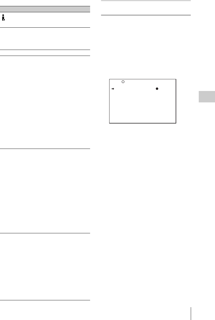
Advanced Operations for Shooting 83
Chapter 4 Shooting
Operation limitations during recording Auto Interval Rec mode settings and
shooting
To make settings
1Display the REC FUNCTION page of
the OPERATION menu.
For details on menu operations, see “Basic
menu operations” on page 163.
2Select CACHE/INTVAL REC, and
turn the MENU knob to display
“A.INT”.
As you turn the MENU knob, the setting
changes as follows: OFF y CACHE y
A.INT y M.INT.
3Select TAKE TOTAL TIME, and turn
the MENU knob to select the desired
total time for shooting.
As you turn the MENU knob, the setting
changes as follows: 5MIN y 10MIN y
15MIN y 20MIN y 30MIN y 40MIN
y 50MIN y 1H y 2H y 3H y 4H
y 5H y 7H y 10H y 15H y 20H
y 30H y 40H y 50H y 70H y
100H.
Here MIN means minutes (5MIN is 5
minutes) and H means hours (1H is one
hour).
4Select REC TIME, and turn the MENU
knob to select the desired time to be
recorded on the disc.
As you turn the MENU knob, the setting
changes as follows: 5SEC y 10SEC y
15SEC y 20SEC y 30SEC y 40SEC
y 50SEC y 1MIN ... 85MIN.
Here SEC means seconds (5SEC is 5
seconds) and MIN means minutes (1MIN is
one minute).
You cannot set a REC TIME that is more
than one thirtieth of TAKE TOTAL TIME.
Item Description
(i.LINK)
S400 connector
Cannot be used.
Time code The internal time code
generator runs in R-RUN mode
regardless of how the F-RUN/
SET/R-RUN switch is set.
Audio signals Not recorded.
Playback control
buttons
•Auto Interval Rec mode and
the consecutive mode of
Manual Interval Rec mode
The EJECT, F REV, F FWD,
NEXT, PREV, PLAY/PAUSE
and STOP buttons are disabled.
To use these buttons, stop
recording by pressing the REC
START button or the VTR
button on the lens.
•The single shot mode of
Manual Interval Rec mode
The F REV, F FWD, NEXT,
PREV, PLAY/PAUSE, and
STOP buttons are disabled. To
use these buttons, exit the
Interval Rec mode by pressing
the EJECT button.
Menu operations The settings of the Interval Rec-
related items on the REC
FUNCTION page of the
OPERATION menu cannot be
changed. To change the settings,
do either of the following.
•Auto Interval Rec mode and
the consecutive mode of
Manual Interval Rec mode
Stop recording by pressing the
REC START button or the VTR
button on the lens.
•The single shot mode of
Manual Interval Rec mode
Exit the Interval Rec mode by
pressing the EJECT button.
When the
camcorder power
is switched off
• When you set the POWER
switch to OFF, the camcorder
will switch off by itself after
disc access has continued for a
few seconds to record the
picture data stored in memory.
• If you remove the battery,
unplug the DC cable, or cut
power to the AC adaptor, picture
data stored before recording
stops (a maximum of ten
seconds) may be lost. Take care
when replacing the battery.
CACHE/INTVAL REC: A.INT
TAKE TOTAL TIME : 5MIN
REC TIME : 5SEC
PRE-LIGHTING : OFF
DISC EXCHG CACHE: OFF
005 REC FUNCTION TOP

Advanced Operations for Shooting
84
Chapter 4 Shooting
The setting value changes within the range
that can be set.
For example: When TAKE TOTAL TIME is
set to 1H, the maximum value of REC TIME
is 2 MIN. (60 minutes divided by 30 gives 2
minutes.)
5As required, select PRE-LIGHTING,
and turn the MENU knob to select the
lighting on-time before recording starts.
As you turn the MENU knob, the setting
changes as follows: OFF y 2SEC y
5SEC y 10SEC.
Note
Set the LIGHT switch on the camcorder to AUTO
to turn on the light before recording. The light
switch must also be set to ON. With these settings,
the light turns on and off automatically. However,
the light remains on continuously if the off time is 5
seconds or less.
When the LIGHT switch is set to MANUAL and
the light switch is set to ON, the light remains on
continuously. (The light does not turn on and off
automatically.)
When the setting is completed, the message
“AUTO INTERVAL **M**S” appears along the
bottom of the viewfinder screen. “**M**S”
indicates the shooting interval.
For example, the message “AUTO INTERVAL
00M04S” indicates that the shooting interval is
four seconds.
The camcorder exits Auto Interval Rec mode
whenever it is powered off. However, the TAKE
TOTAL TIME, REC TIME, and PRE-
LIGHTING settings are maintained. You do not
need to set them again the next time you use Auto
Interval Rec mode.
To shoot and record
1After performing the basic procedures
for shooting and recording, following
the instructions in “Basic Procedure for
Shooting” (page 76), secure the
camcorder so that it will not move.
2Press the REC START button or the
VTR button on the lens.
The camcorder starts recording in Auto
Interval Rec mode. When you use the PRE-
LIGHTING function, recording starts after
the light is switched on.
The actual recording to disc begins when the
camcorder has saved about ten seconds of
video in memory, so disc access is
intermittent.
While recording in Auto Interval Rec mode,
the TALLY (green tally) indicator in the
viewfinder flashes (4 flashes/second) and the
message “AUTO INTERVAL **M**S”
flashes on the viewfinder screen.
When the camcorder is capturing the picture
in memory, the REC (recording, red tally)
indicator in the viewfinder lights.
After the length of time for recording on the
disc (REC TIME) has elapsed, the camcorder
automatically stops recording.
To interrupt shooting
Press the REC START button or the VTR button
on the lens.
Disc access may occur for recording picture data
already stored in memory.
To continue shooting
Press the REC START button or the VTR button
on the lens again.
To exit Auto Interval Rec mode
Do either of the following.
• Set the POWER switch to OFF.
• Set CACHE/INTVAL REC to OFF on the REC
FUNCTION page of the OPERATION menu.
Time required for shooting and time required for
recording on the disc
Auto Interval Rec mode is effective for shooting
objects that move very slowly. To use this
function, you need to set the total time for
shooting (TAKE TOTAL TIME) and the length
of time for recording on the disc (REC TIME).
The time required for shooting is the time
required to capture the very slowly moving
subject, and the camcorder must be arranged so
that during this time the subject is always in the
frame.
The disc recording time indicates the running
time of the completed recording. The camcorder
calculates the time-lapse interval from these two
times.
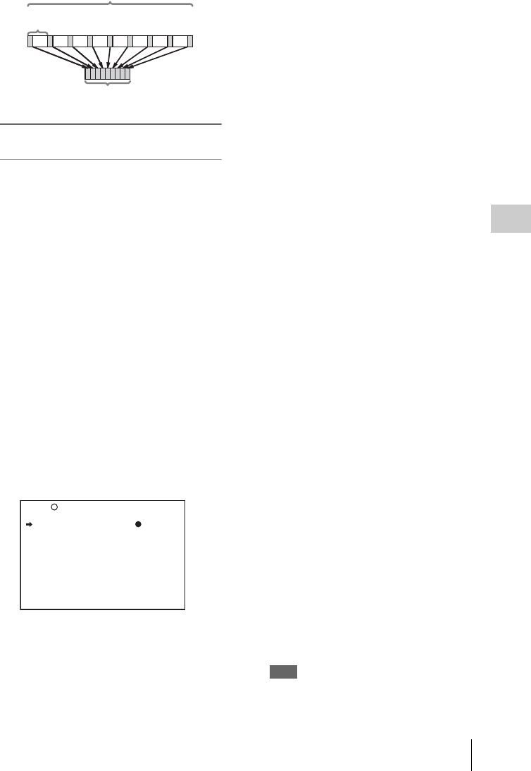
Advanced Operations for Shooting 85
Chapter 4 Shooting
Manual Interval Rec mode settings and
shooting
Manual Interval Rec has the following two
modes.
Single shot mode: Each time the REC START
button or VTR button on the lens is pressed,
the camcorder captures to memory a single
shot consisting of the specified number of
video frames.
Consecutive mode: Once the REC START
button or VTR button on the lens is pressed,
the camcorder captures consecutive shots to
memory at the specified interval, with each
shot consisting of the specified number of
video frames.
To make settings
1Display the REC FUNCTION page of
the OPERATION menu.
For details on menu operations, see “Basic
menu operations” on page 163.
2Select CACHE/INTVAL REC, and
turn the MENU knob to display
“M.INT”.
As you turn the MENU knob, the setting
changes as follows: OFF y CACHE y
A.INT y M.INT.
When M. INT appears, the camcorder is in
Manual Interval Rec mode and the TALLY
(green tally) indicator in the viewfinder
flashes.
3Select NUMBER OF FRAME, and turn
the MENU knob to select the desired
number of frames to be recorded in
each shot.
As you turn the MENU knob, the setting
changes as follows: 1 y 3 y 6 (when
SYSTEM LINE is set to 720 and REC
FORMAT is set to HD422 50, HD420 HQ, or
HD420 SP: 2 y 6 y 12).
4Select TRIGGER INTERVAL, and
turn the MENU knob to select the
desired trigger mode or length of
interval.
As you turn the MENU knob, the setting
changes as follows: M y 1SEC y 2SEC
y 3SEC y 4SEC y 5SEC y 6SEC
y 7SEC y 8SEC y 9SEC y 10SEC
y 15SEC y 20SEC y 30SEC y
40SEC y 50SEC y 1MIN y 2MIN y
3MIN y 4MIN y 5MIN y 6MIN y
7MIN y 8MIN y 9MIN y 10MIN y
15MIN y 20MIN y 30MIN y 40MIN
y 50MIN y 1H y 2H y 3H y 4H
y 6H y 12H y 24H.
Here SEC means seconds (5SEC is 5
seconds) and MIN means minutes (1MIN is
one minute).
M: The single shot mode (recording only one
shot after one operation). In the
viewfinder, the TALLY (green tally)
indicator flashes twice per second.
A setting value other than “M”: The
consecutive mode (recording shots
repeatedly after one operation). In the
viewfinder, the TALLY (green tally)
indicator flashes four times per second.
5When a setting value other than “M”
(the consecutive mode) is selected in
step 4, select PRE-LIGHTING, and
turn the MENU knob to select the
lighting on-time before recording starts
as required.
As you turn the MENU knob, the setting
changes as follows: OFF y 2SEC y
5SEC y 10SEC.
Note
Set the LIGHT switch on the camcorder to AUTO
to turn on the light before recording. The light
switch must also be set to ON. With these settings,
Total time for shooting (TAKE TOTAL TIME)
Shooting interval
Time for recording on the disc
(REC TIME)
CACHE/INTVAL REC: M.INT
NUMBER OF FRAME : 1
TRIGGER INTERVAL: M
DISC EXCHG CACHE: OFF
005 REC FUNCTION TOP

Advanced Operations for Shooting
86
Chapter 4 Shooting
the light turns on and off automatically. However,
the light remains on continuously if the off time is 5
seconds or less.
When the LIGHT switch is set to MANUAL and
the light switch is set to ON, the light remains on
continuously. (The light does not turn on and off
automatically.)
When the setting is completed, the following
message appears along the bottom of the
viewfinder screen.
In single shot mode: MANU INTERVAL *
FRAME
In consecutive mode: MANU INTERVAL *
SEC * FRAME
“* SEC” indicates the length of interval and “*
FRAME” indicates the number of frames.
The camcorder exits Manual Interval Rec mode
whenever it is powered off. However, the
NUMBER OF FRAME, TRIGGER INTERVAL,
and PRE-LIGHTING settings are maintained.
You do not need to set them again the next time
you use Manual Interval Rec mode.
To shoot and record
1After performing the basic procedures
for shooting and recording, following
the instructions in “Basic Procedure for
Shooting” (page 76), secure the
camcorder so that it will not move.
2Press the REC START button or the
VTR button on the lens.
The camcorder starts recording in Manual
Interval Rec mode. When you use the PRE-
LIGHTING function, recording starts after
the light is switched on.
While recording in Manual Interval Rec
mode, the TALLY (green tally) indicator in
the viewfinder flashes (2 or 4 flashes/second)
and the message “MANU INTERVAL (*
SEC) * FRAME” flashes on the viewfinder
screen.
To exit Manual Interval Rec mode
Do one of the following.
• In the single shot mode, press the EJECT
button.
• In the consecutive mode, press the REC START
button or the lens VTR button to stop recording.
• Set the POWER switch to OFF.
After the camcorder has exited from Manual
Interval Rec mode, it records picture data stored
in memory to the disc.
Even if you run out of free disc capacity while
recording, you can continue recording by using
the Disc Exchange Cache function. This function
enables seamless recording over extended
recording sessions, too long to fit on one disc, by
recording to the unit’s internal memory while you
exchange the disc.
Note
The unit’s internal memory is not unlimited, so the video
and audio may be interrupted if it takes too long to
exchange the disc.
To enable the Disc Exchange Cache
function
1Display the REC FUNCTION page of
the OPERATION menu.
For details on menu operations, see “Basic
menu operations” on page 163.
2Select DISC EXCHG CACHE, and
turn the MENU knob to display “ON”.
The TALLY (green tally) indicator lights in
the viewfinder.
To exchange discs with the function
enabled
When the disc exchange cache function is
enabled, the following procedure allows you to
exchange discs while continuing to record.
1Press the REC START button or the
VTR button on the lens to start
recording.
The REC (recording, red tally) indicator
lights in the viewfinder, and the tally
indicator lights.
2Press the EJECT button with the unit
still in the recording state.
To exchange discs while record-
ing (Disc Exchange Cache func-
tion)

Advanced Operations for Shooting 87
Chapter 4 Shooting
The REC (recording, red tally) indicator in
the viewfinder and the tally indicator flash
(once per second), and the disc is ejected.
If the message “DISC FULL!” appears
You can continue recording, because video
and audio continue to be saved to internal
memory. Press the EJECT button and
continue to step 3.
Note
Do not stop recording before pressing the EJECT
button. If you stop recording, the unit will stop
storing video and audio in internal memory and this
function will not work.
3Quickly remove the disc, insert a
formatted blank disc, and close the
cover.
When the disc is loaded, the REC (recording,
red tally) indicator in the viewfinder and the
tally indicator change to lit, and recording
continues.
If the REC indicator and tally indicator
begin flashing rapidly during the disc
exchange
If the indicators change to flashing twice per
second, that means that the unit’s internal
memory is almost full. Complete the disc
exchange quickly.
Note
Recording may not start immediately if you insert
an unformatted disc, or a disc that already contains
a large number of clips. As a result, the video and
audio may be interrupted.
A retake function is available, making it easy to
erase and retake the most recently recorded clip.
To use the retake function, you need to assign it
to one of the ASSIGN 1/3/4 switches or COLOR
TEMP. button in advance.
For details, see “Assigning functions to ASSIGN
switches” on page 178.
Example: After recording clip 3, you want to
delete it and record a new clip 3 after clip 2.
To retake the most recent clip
With recording paused or after the end of a
recording review (see page 77), proceed as
follows.
1Hold down the button to which the
retake function has been assigned.
While the button is held down, the last frame
of the recorded clip and the message “PUSH
RET FOR CLIP DELETE” appears.
2In this state, press the RET button.
The message “DELETING LAST CLIP”
appears, and the processing for deleting the
last recorded clip begins.
When the deleting has finished, the message
“LAST CLIP WAS DELETED” appears.
Note
If an operation (other than recording review) which is not
a retake operation is carried out after the last clip has
been recorded, the retake function does not work even
when the camcorder is in the recording pause state.
In this case, the message “RE-TAKE NOT
ALLOWED!” appears. When you want to replace the
last clip with a new clip, delete the clip (see page 112).
Once you carry out a retake operation, the last clip is
deleted even if you do not carry out a recording operation
afterwards.
About the automatic title generation
function
By default, clips on each disc are assigned names
in the range C0001.MXF to C9999.MXF. For this
reason, two discs can contain clips with the same
names. The automatic title generation function
allows you to assign titles to all of the clips on
several discs, which facilitates clip management.
For example, if the titles TITLE00001 to
TITLE00020 are assigned to clips C0001.MXF to
C0020.MXF on disc 1, then the titles
TITLE00021 to TITLE00037 are assigned to
clips C0001.MXF to C0017.MXF on disc 2.
Titles are made up of prefixes, up to 10 characters
in length, and five-digit serial numbers such as
TITLE 00001.
Retaking the most recent clip
Clip 1 Clip 2 Clip 3
New clip
Assigning user-defined clip titles
automatically
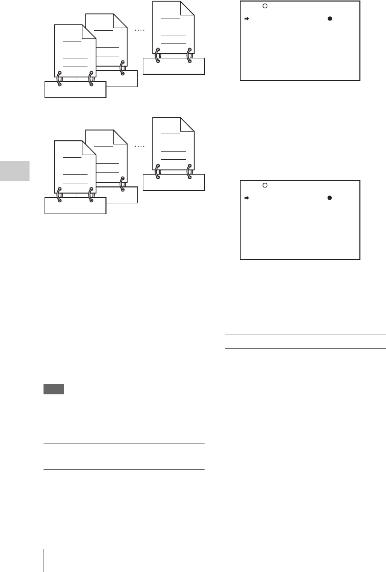
Advanced Operations for Shooting
88
Chapter 4 Shooting
Setting the title prefix
You can assign title prefixes by choosing from a
prefix list stored in internal memory, or by
entering the prefix directly.
However, to choose from a prefix list, you must
create the list beforehand on a computer and
transfer it to the unit's internal memory with a
“Memory Stick”.
Setting the initial value of the serial number
The initial value of the serial number can be set to
00001 (the default) or to any other number. The
number is automatically incremented by 1 each
time you record a clip. When it reaches 99999, it
returns to 00001 for the next clip.
Note
Duplicate clip titles can be generated depending on the
serial number setting, for example if you reset the serial
number to the original value after recording several clips.
Care should be taken when setting the serial number.
To assign user-defined titles
automatically when clips are recorded
(How to select an item in the menu screen: Turn
the MENU knob to move b to the desired item.)
1Display the CLIP TITLE page of the
OPERATION menu.
For details on menu operations, see “Basic
menu operations” on page 163.
2Select “TITLE” and then press the
MENU knob.
3Turn the MENU knob to display
“ENABL” and then press the MENU
knob.
Clip titles will be generated automatically if
you record in this state.
The title of the next clip to be recorded will
be a combination of the prefix in the PREFIX
field and the serial number in the NUMERIC
field.
To create a list of title prefix strings
Prepare the data beforehand according to the
following rules.
File name
Assign the name “TITLES.TXT” to the file.
Input format
Enter title prefixes one at time, separated by
newline (CRLF) characters.
Prefixes can be up to 10 characters long. A prefix
file can contain up to 20 prefixes.
Allowable characters
•Digits: 0 to 9
•Alphabetic characters: a to z, A to Z
• The following symbols:!, #, $, %, &, ', ( , ), ~, =,
-, ^, @, [, ], {, }, +, ; (semicolon), , (comma), .
(period), _ (underscore)
•Space
C0020.MXF
TITLE00020
C0002.MXF
TITLE00020
C0017.MXF
TITLE00037
C0002.MXF
TITLE00022
TITLE00001
C0001.MXF
TITLE00021
C0001.MXF
Clips recorded on Disc 1
Clips recorded on Disc 2
TITLE : DSABL
027 CLIP TITLE TOP
TITLE : ENABL
SELECT PREFIX : EXEC
CLEAR NUMERIC : EXEC
LOAD PREFIX DATA: EXEC
PREFIX : TITLE
NUMERIC : 00001
027 CLIP TITLE TOP

Advanced Operations for Shooting 89
Chapter 4 Shooting
Title prefix list example
Tennis<CRLF>
Basketball<CRLF>
Skiing_1<CRLF>
Skiing_2<CRLF>
To transfer a title prefix list to the
internal memory of the camcorder
(How to select an item in the menu screen: Turn
the MENU knob to move b to the desired item.)
1Copy the title prefix file (TITLES.TXT)
to the following folder on the “Memory
Stick”.
\\MSSONY\PRO\XDCAM\GENERAL\VA
L_LIST
Note
This folder is created when you insert a “Memory
Stick” into the camcorder. Do not create this folder
yourself on a computer.
2Insert a “Memory Stick” with the title
prefix file (TITLES.TXT) into the
“Memory Stick” slot of the camcorder.
3On the CLIP TITLE page of the
OPERATION menu (see page 137),
select “LOAD PREFIX DATA” and
then press the MENU knob.
“MEMORY STICK ACCESS” appears, and
the file on the “Memory Stick”
(TITLES.TXT) is transferred to the internal
memory of the unit.
The message “COMPLETE!” appears when
the transfer finishes.
Note
The message “FILE NOT FOUND!” appears if no
list of title prefixes is found.
Check the location where the file is stored on the
“Memory Stick”.
To select a prefix from the title prefix list
(How to select an item in the menu screen: Turn
the MENU knob to move b to the desired item.)
1Display the CLIP TITLE page of the
OPERATION menu.
For details on menu operations, see “Basic
menu operations” on page 163.
2Select “SELECT PREFIX” and then
press the MENU knob.
A list of up to 20 title prefixes appears.
Note
When no list of title prefixes has been transferred to
the internal memory of this unit, only the initial
value “TITLE” appears.
3Select the desired title prefix from the
list, and then press the MENU knob.
The CLIP TITLE page appears again, and the
selected prefix appears in the PREFIX field.
To enter a title prefix directly
(How to select an item in the menu screen: Turn
the MENU knob to move b to the desired item.)
1Display the CLIP TITLE page on the
OPERATION menu.
For details on menu operations, see “Basic
menu operations” on page 163.
2Select “PREFIX” and then press the
MENU knob.
A prefix string appears.
3Move x onto the character you want to
change, and then press the MENU
knob.
4Turn the MENU knob to move x onto
the desired character in the list of
selectable characters, and then press
the MENU knob.
001: Tennis
002: Basketball
003: Skiing_1
004: Skiing_2
005: Athletics
006: Aquatics
007: Cycling
008: Softball
009: Fencing
010: Sailing
P00 TITLE PREFIX ESC
TITLE : ENABL
SELECT PREFIX : EXEC
CLEAR NUMERIC : EXEC
LOAD PREFIX DATA: EXEC
PREFIX : TITLE
!#$%&'()+,-.0123456789;
=@ABCDEFGHIJKLMNOPQRSTUV
WXYZ[]^_abcdefghijklmnop
qrstuvwxyz{}~
INS DEL RET ESC END
027 CLIP TITLE TOP

Advanced Operations for Shooting
90
Chapter 4 Shooting
5Repeat steps 3 and 4 to enter the
remaining characters.
6When you have finished entering the
prefix, turn the MENU knob to move x
to “END” and then press the MENU
knob.
The camcorder exits prefix input mode, and
the original CLIP TITLE page appears.
To set the initial value of the clip title
serial number
You can set the initial value of the clip title serial
number to 00001 (default) or to any 5-digit value.
To return the initial value to 00001
(How to select an item in the menu screen: Turn
the MENU knob to move b to the desired item.)
1Display the CLIP TITLE page on the
OPERATION menu.
For details on menu operations, see “Basic
menu operations” on page 163.
2Select “CLEAR NUMERIC”and then
press the MENU knob.
The message “CLEAR OK? bYES NO”
appears.
3Select “YES” and then press the MENU
knob.
The value in the NUMERIC field returns to
00001.
To set the initial value to any number
(How to select an item in the menu screen: Turn
the MENU knob to move b to the desired item.)
1Display the CLIP TITLE page on the
OPERATION menu.
For details on menu operations, see “Basic
menu operations” on page 163.
2Select “NUMERIC” and then press the
MENU knob.
3Move x onto the digit you want to
change, and then press the MENU
knob.
4Turn the MENU knob to move x onto
the desired digit in the list of selectable
digits, and then press the MENU knob.
5Repeat steps 3 and 4 to enter the
remaining digits.
6When you have finished entering the
value, turn the MENU knob to move x
to “END” and then press the MENU
knob.
The camcorder exits numeric input mode,
and the original CLIP TITLE page appears.
To check clip titles
Press the THUMBNAIL button to display the
thumbnail screen, and select the clip whose title
you want to check.
The title of the selected clip appears in the upper
left of the screen.
See “Clip thumbnail screen” (page 96) for more
information about the thumbnail screen.
Notes
• It is not possible to specify 00000 as the initial value.
Even if you enter 00000, the value is reset to 00001
when the camcorder exits numeric input mode.
• The value of the serial number is incremented by 1
every time a title is generated. When the value reaches
99999, the next number restarts from 00001.
• Duplicate clip titles can be generated if you reset the
serial number after recording several clips or the same
is true depending on the value setting. Care should be
taken when setting the serial number.
The following standard format names are
assigned automatically to clips and clip lists that
are created or recorded by XDCAM devices.
Clips: C0001.MXF to C9999.MXF
Clip lists: E0001E01.SMI to E0099E01.SMI
When you record or create clips and clip lists, you
can assign user-defined names instead of the
standard format names. Assigning meaningful
names to clips and clip lists can facilitate file
management.
Limitations
• Letters, numbers and symbols from the Unicode
2.0 character set can be used.
However, the following control characters and
symbols cannot be used.
-Control characters: U+0000 to U+001F,
U+007F
-Symbols: ", *, /, :, <, >, ?, \, |
Assigning user-defined names to
clips and clip lists
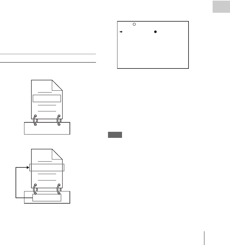
Advanced Operations for Shooting 91
Chapter 4 Shooting
• Depending on the character type, the length of
name (“C*” part) may be limited to 14
characters. (The limit for ASCII characters is 56
characters.)
• All file name extensions are converted
automatically to uppercase.
• Titles are used as user-defined clip names on
this unit. Therefore, the available characters are
limited to those supported by the title function.
• Files generated along with clips and clip lists
are assigned the same names (the “C*” or “E*”
part of the following file names).
-Clips: Metadata files (C*M01.XML), user
metadata file (C*M02.KLV), proxy AV data
files (C*S01.MXF)
-Clip lists: Metadata files (E*M01.XML)
• The following names cannot be assigned.
-Clips: C0000.MXF
-Clip lists: E0000E01.SMI, E0100E01.SMI to
E9999E01.SMI, E0000.SMI, E0100.SMI to
E9999.SMI
• The following names should be avoided.
-Clips: C5000.MXF to C9999.MXF
-Clip lists: E0001.SMI to E0099.SMI
To assign clip names on this unit
The title assigned to a clip is also used as the name
of that clip (or the file name).
(How to select an item in the menu screen: Turn
the MENU knob to move b to the desired item.)
1Before starting, set TITLE on the CLIP
TITLE page of the OPERATION menu
to ENABL and set a title (see page 88).
For details on menu operations, see “Basic
menu operations” on page 163.
2Display the FILE NAMING page of the
OPERATION menu.
3Select NAMING FORM and then press
the MENU knob.
4Turn the MENU knob to display
“FREE” and then press the MENU
knob.
You can now enter a user-defined name.
5Turn the MENU knob to select “AUTO
NAMING” and then press the MENU
knob.
6Turn the MENU knob to display
“TITLE” and then press the MENU
knob.
The same name will now be given to newly
recorded clips.
Notes
• An FTP client software that supports UTF-8 is
required to use Unicode characters other than ASCII
characters. Command prompt FTP commands do not
support UTF-8.
• When the first letter of the title setting on the CLIP
AUTO TITLING menu is a space or period (.), the clip
name is the title string minus the first letter.
To use clip names and clip list names by FAM
and FTP
Carry out steps 2 to 4 of “To assign clip names on
this unit” (page 91).
It is now possible to write, transfer, and rename
clips and clip lists with user-defined names over
C0001.MXF
TITLE00001
TITLE00001.MXF
TITLE00001
When sub item “AUTO NAMING” is set to
“C****”
When sub item “AUTO NAMING” is set to
“TITLE”
NAMING FORM: FREE
AUTO NAMING: C****
028 FILE NAMING TOP

Advanced Operations for Shooting
92
Chapter 4 Shooting
file access mode (FAM) connections (see page
199) and FTP connections (see page 203).
To set clip names by using planning
metadata
Planning metadata is a file that contains metadata
about the clips to be shot and recorded.
The following two types of clip name strings can
be written in a planning metadata file.
• The ASCII format name that appears in the
viewfinder 1)
• The UTF-8 format name that is actually
registered as the clip name 2)
1) It is also possible to display the UTF-8 format name,
or no name (see page 123).
2) When no UTF-8 format name string is specified, the
ASCII format name string is registered as the actual
clip name.
By loading a file from one of the following
locations into the unit's memory before starting to
shoot, you can register the names in the file as clip
names.
To load files, use a GUI screen (see page 121).
File creation rules
a) The General/Sony/Planning directory is generated
automatically when you format a disc.
Clip name string format
In a text editor, modify the two fields in the
<Title> tag that contain the clip name strings (the
shaded fields in the example below).
Enter a name in the first field in ASCII format (up
to 52 characters), and enter another name in the
second field in UTF-8 format (up to 52 bytes).
Clip name string example
<?xmlspversion="1.0"spencoding="UTF-8"?>3
<PlanningMetadataspxmlns="http://
xmlns.sony.net/pro/metadata/
planningmetadata"spassignId="
P0001"spcreationDate="
2008-01-20T17:00:00+09:00"splastUpdate="
2008-03-28T10:30:00+09:00"spload="
false"spversion="1.00">3
<PropertiessppropertyId="
assignment"spupdate="2008-01-20T09:00:
00+09:00"spmodifiedBy="Chris">3
<TitlespusAscii=" "spxml:lang
="en"> </
Title>3
</Properties>3
</PlanningMetadata>3
In the above example, sp indicates a space and 3
indicates a carriage return.
Notes
• When creating a file, write each line as a single
statement, inserting carriage returns only at the
indicated carriage return locations, and inserting no
unspecified spaces.
• If the UTF-8 format string is longer than 52 characters,
the ASCII format string is used as the clip name string.
Fuji.MXF
Sakura.SMI
User-defined clip names can be used by FAM
and FTP
User-defined clip list names can be used by FAM
and FTP
File location File name
Professional Disc:
General/Sony/
Planning
directory a)
• Format that can be used in
the General directory (see
page 198)
• Extension: XML
USB Flash drive:
General/Sony/
Planning directory
• ASCII characters (up to
63 characters including
the extension)
• Extension: XML
Typhoon
Typhoon_Strikes_Tokyo

Advanced Operations for Shooting 93
Chapter 4 Shooting
Setting clip names
1Load a planning metadata file
containing clip names into the unit’s
memory (see page 121).
2Carry out steps 2 to 5 of “To assign clip
names on this unit” (page 91).
3Turn the MENU knob to display
“PLAN”, and then press the MENU
knob.
Each time that you start recording, the unit
automatically creates clip names using the
names specified in the planning metadata
file. An underscore (_) and a three-digit serial
number (001 to 999) is appended to each clip
name.
Examples of automatically generated clip
names
• Clip names displayed in the viewfinder:
Typhoon_001, Typhoon_002, ...
• The actually recorded clip names:
Typhoon_Strikes_Tokyo_001,
Typhoon_Strikes_Tokyo_002, ... 1)
1) When display of the ASCII format clip name has
been selected (see page 123).
Notes
• The serial numbers return to 001 on the next
recording operation if you reach number 999.
• Serial numbers are not reset when you power the
unit off or exchange discs (newly generated
numbers are continuous on the old ones).
• If the ASCII format clip name string is longer
than 14 characters, it is displayed in the
viewfinder as the first 8 characters + x
(abbreviated) + the last 4 characters, for a total of
13 characters.
To check clip names
Press the THUMBNAIL button to display the
thumbnail screen, and select the clip whose name
you want to check.
The name of the selected clip appears in the upper
left of the screen.
See “Clip thumbnail screen” (page 96) for more
information.
Note
The item at the upper left of the screen is displayed
according to the following order of priority.
Title > user-defined clip name > standard format clip
name
Therefore, the display of this item changes as follows,
depending on whether or not there is a title.
• When a title has been set as a clip name on this unit,
the title is displayed for clips recorded on this unit.
• The user-defined name or standard format name is
displayed for clips without a title.
To check clip information (name, title,
etc.)
For details, see “Checking clip properties”
(page 108).
You can select between recording of data shot by
the camera and recording of data input from an
external device by using a menu or by using the
ASSIGN 2 switch.
Notes
• If you want to use the ASSIGN 2 switch, you must
assign the video switching function to the ASSIGN 2
switch beforehand (see page 178).
• Switching by the ASSIGN 2 switch takes priority over
switching by the menu. (Switching by menu is not
possible if the function has been assigned to the
ASSIGN 2 switch.)
• Video breakup may occur around the switch if you
switch the input during recording.
• Camera video is recorded if you switch to external
input without inputting an external video signal to the
SDI IN (OPTION) connector or the GENLOCK IN
connector.
• It is not possible to record external input video with a
changed aspect ratio.
To record SDI signals (with the CBK-
HD01 installed)
When the optional CBK-HD01 HD/SD SDI Input
Board is installed in this unit, you can record HD-
SDI or SD-SDI signals input to the SDI IN
(OPTION) connector. When an HD recording
format (MPEG HD422 50, or MPEG HD420 HQ/
SP) is selected, SD-SDI signals are upconverted
to HD signals before recording.
Notes
• It is not possible to record HD-SDI signals when an SD
recording format (MPEG IMX 50/40/30, or DVCAM)
is selected.
Recording video from external
devices

Advanced Operations for Shooting
94
Chapter 4 Shooting
• The system frequency and resolution (HD-SDI input
only) of input signals must match the current settings
of this unit. Otherwise the input signals cannot be
recorded.
• Only audio signals embedded in SDI signals are
recorded, regardless of the settings of the AUDIO IN
CH-1/CH-2/CH-3/CH-4 switches.
1Display the SOURCE SEL page of the
OPERATION menu.
For details on menu operations, see “Basic
menu operations” on page 163.
2Select REC VIDEO SOURCE, and turn
the MENU knob to display “EXT”.
3Select EXT VIDEO SOURCE, and turn
the MENU knob to select the desired
signal to be recorded.
As you turn the MENU knob, the setting
changes as follows: HDSDI 1) y SDSDI
y VBS 2).
1) HDSDI cannot be selected when an SD recording
format is selected.
2) Does not appear when the optional CBK-SC02
Analog Composite Input Board is not installed.
After you complete this setting, you can record
the video signals of external devices by inputting
the SDI signals selected in step 3 to the SDI IN
(OPTION) connector.
Recording analog composite signals
(with the CBK-SC02 installed)
When the optional CBK-SC02 Analog
Composite Input Board is installed in this unit,
you can record analog composite signals input to
the GENLOCK IN connector. When an HD
recording format (MPEG HD422 50, or MPEG
HD420 HQ/SP) is selected, analog composite
signals are upconverted to HD signals before
recording.
Note
Even if the GENLOCK item on the GENLOCK page of
the MAINTENANCE menu is set to OFF, the unit
automatically genlocks to external video signals that are
input to the GENLOCK IN connector. When
GENLOCK is set to OFF, the genlock is cancelled when
the input of external video signals stops and the unit
switches to camera shooting.
1Display the SOURCE SEL page of the
OPERATION menu.
2Select REC VIDEO SOURCE, and turn
the MENU knob to display “EXT”.
3Select EXT VIDEO SOURCE, and turn
the MENU knob to display “VBS”. 1)
1) Does not appear when the optional CBK-SC02
Analog Composite Input Board is not installed.
After you complete this setting, you can record
external video signals by inputting analog
composite signals to the GENLOCK IN
connector.

Overview 95
Chapter 5 Operations in GUI Screens
You can perform scene searches, play the
searched scenes, and select scenes (edit clip list)
in Graphical User Interface (GUI) screens. The
GUI screens are your gateways to discs and the
data saved on discs.
The most important GUI screens are:
Clip thumbnail screen: Displays thumbnails of
clips on the disc. “Clip” is displayed as the
title at the upper left of the screen (see
page 96).
Clip list thumbnail screen: Displays thumbnails
of sub clips in a clip list. “Clip List” is
displayed as the title at the upper left of the
screen (see page 96).
There are also two playback screens:
Clip playback screen: Playback screen for
normal video
Clip list playback screen: Playback screen for
clip list video
You will use the THUMBNAIL/ESSENCE
MARK button 1 and the SUB CLIP/DISC
MENU button 2 to switch between these four
screens. Each press of these buttons switches
between the screens as shown in the following
figure. The THUMBNAIL and SUB CLIP
indicators light as follows, according to the type
of screen that is currently displayed.
Notes
•To switch between these four screens, a disc
with recorded clips must be loaded in the unit.
• The GUI screens can display clip name, titles,
and other information in European languages
and Japanese, but they cannot display Chinese.
Chapter5Operations in GUI Screens
Overview
Switching between GUI screens
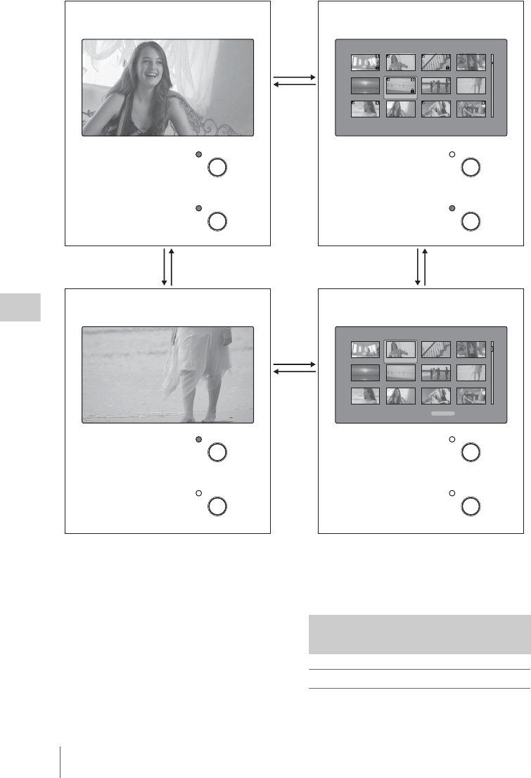
Overview
96
Chapter 5 Operations in GUI Screens
The other thumbnail screens are:
• Expand thumbnail screen
• Chapter thumbnail screen
• Essence mark thumbnail screen
Clip thumbnail screen
This screen displays thumbnails of clips on the
disc in the order that they were recorded. You can
1
1
22
Clip List:E0001 002/013
TC 00:00:00:00
TC 00:00:28:08
TC 00:00:59:16
DATE&TIME 28 JUL 2006 19:55 TOTAL DUR 00:01:31:16
TC 00:00:04:14
TC 00:00:35:15
TC 00:01:06:18
TC 00:00:12:04
TC 00:00:46:08
TC 00:01:13:11
TC 00:00:20:13
TC 00:00:53:22
TC 00:01:17:27
Clip:C0006 006/040
TC 00:23:00:25
TC 00:25:49:23
TC 00:28:06:09
DATE&TIME 30 NOV 2005 13:38 DUR 0:00:10:23
TC 00:23:40:07
TC 00:26:22:10
TC 00:28:22:02
TC 00:24:45:11
TC 00:27:19:04
TC 00:23:34:18
TC 00:25:06:14
TC 00:27:51:09
TC 00:23:54:22
22
1
1
THUMBNAIL
ESSENCE
MARK
SUB CLIP
DISC MENU
THUMBNAIL
ESSENCE
MARK
SUB CLIP
DISC MENU
THUMBNAIL
ESSENCE
MARK
SUB CLIP
DISC MENU
THUMBNAIL
ESSENCE
MARK
SUB CLIP
DISC MENU
Clip playback screen a) Clip thumbnail screen
Clip list playback screen a), b) Clip list thumbnail screen b)
Unlit
Unlit Unlit
Lit
Lit
Lit
Unlit
Lit
a) The playback screens appear when the LCD monitor is switched to display of video with (CHAR) or without
(MONI) superimposed text. Press the DISP SEL/EXPAND button to switch the LCD monitor to these modes (see
page 21).
b) The clip list playback screen appears when a clip list is loaded into the unit’s memory (see page 119).
Information and controls in
thumbnail screens
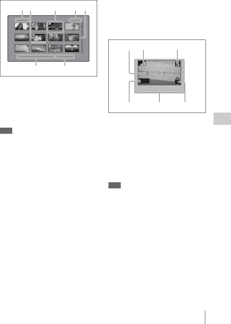
Overview 97
Chapter 5 Operations in GUI Screens
use this screen to work with clips – deleting or
locking them, selecting their index pictures,
adding them to clip lists, and so on.
aClip name
Displays the name of the selected clip. When the
clip has a title, it is displayed as “TITLE00001”
(see page 87). Clip names can be displayed in
European languages when the area of use (see
page 40) is set to “NTSC AREA” or “PAL
AREA”.
Note
To display the clip title, Settings >Display Title in the
Disc Menu needs to be set to On.
bSelection frame
Indicates that the thumbnail is selected. To select
another thumbnail, move the frame (see
page 104). Multiple selection frames appear
when multiple thumbnails are selected (see
page 104).
cClip number/total number of clips
Displays the total number of clips on the disc, and
the number of the selected clip.
dScrollbar
When not all of the thumbnails can be displayed
in the thumbnail display area, the position of the
slider shows the relative position of the currently
displayed clips, and the length of the slider shows
the relative length of currently displayed clips
within all of the clips.
When you have a large number of thumbnails,
you can save time by using the Skip Scroll
function to jump directly to the thumbnail you
want (see page 104).
eClip date and time
Displays the date and time when the selected clip
was shot and recorded.
fDuration
Displays the duration (recording time) of the
selected clip.
1Thumbnail display items
aIndex picture
Displays an image to stand for the content of the
clip. The index picture is normally the first frame
of the clip.
bIndex picture changed mark
This mark, like the folded-over corner of a page
that you want to remember, appears when the
index picture has been changed to any frame other
than the first frame of a clip (see page 108).
Note
When you cue up a clip, the unit always cues up the first
frame, even when the index picture has been changed to
a different frame.
cS mark
This mark appears when shot marks or multiple
Rec Start essence marks have been set in the clip
(see page 80).
The chapter thumbnail screen can be displayed
for clips that show this mark (see page 99).
dClip flag icon
Displays the corresponding icon when a clip flag
(OK/NG/KP (KEEP)) is set in the clip (see
page 111).
Clip:C0006 006/040
TC 00:23:00:25
TC 00:25:49:23
TC 00:28:06:09
DATE&TIME 30 NOV 2005 13:38 DUR 0:00:10:23
TC 00:23:40:07
TC 00:26:22:10
TC 00:28:22:02
TC 00:24:45:11
TC 00:27:19:04
TC 00:23:34:18
TC 00:25:06:14
TC 00:27:51:09
TC 00:23:54:22
KP NG OK
12 3 4
1
56
TC 00:26:22:10
OK
546
213
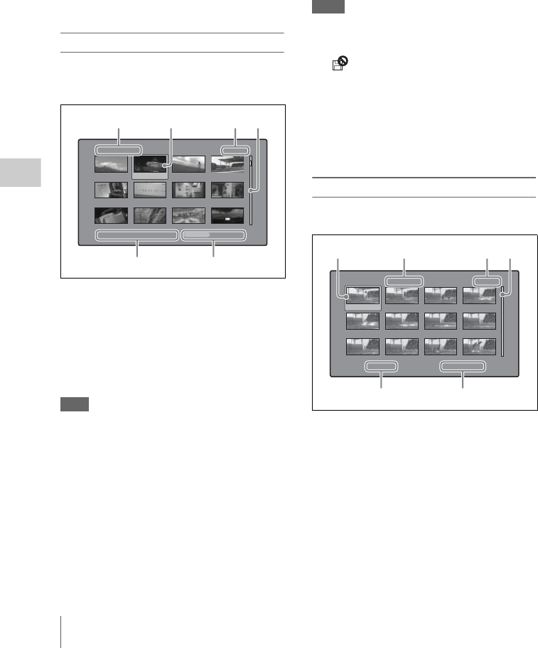
Overview
98
Chapter 5 Operations in GUI Screens
eClip and frame information
Displays the clip or frame information selected
with the Clip Information item in the Thumbnail
Menu (see page 107). The factory default
selection is the timecode of the first frame or the
timecode of the thumbnail frame.
fLock icon
This icon appears when the clip is locked
(protected) (see page 111). Clips cannot be
deleted and their clip information cannot be
changed when this mark is displayed.
Clip list thumbnail screen
This screen displays thumbnails of the clips in the
current clip list. You can use this screen to create
and edit clips lists.
aClip list name
Displays the name of the clip list. When the clip
list has a title, it is displayed as “TITLE00001”
(see page 87). Clip list names can be displayed in
European languages when the area of use (see
page 40) is set to “NTSC AREA” or “PAL
AREA”.
Note
To display the clip list title, Settings >Display Title in the
Disc Menu needs to be set to On.
bSelection frame
See the description in “Clip thumbnail screen” (page
96).
cSub clip number/number of sub clips
Displays the total number of sub clips in the clip
list, and the number of the selected sub clip.
dScrollbar
See the description in “Clip thumbnail screen” (page
96).
eClip list date and time
Displays the date and time when the clip list was
created, or the date and time of its most recent
modification. An asterisk (*) appears after the
date and time of creation when the current clip list
has not been saved to the disc.
Notes
• “New File” appears when no clip list has been loaded
into the unit’s memory, and when a clip list has been
cleared from the unit’s memory.
• A mark appears before the date of creation or
modification when a disc is write inhibited. You can
create clip lists when the disc is write inhibited, but you
cannot save them.
fTotal duration
Displays the total duration of all sub clips in the
clip list.
Expand thumbnail screen
This screen displays thumbnails of equally sized
divisions of the selected clip.
aSelection frame
See the description in “Clip thumbnail screen” (page
96).
bClip number/total clips x number of
divisions
Displays the number of the selected clip, the total
number of clips on the disc, and the number of
times that the selected clip has been divided to
display the expansion thumbnails.
Clip List:E0001 002/013
TC 00:00:00:00
TC 00:00:28:08
TC 00:00:59:16
DATE&TIME 28 JUL 2006 19:55 TOTAL DUR 00:01:31:16
TC 00:00:04:14
TC 00:00:35:15
TC 00:01:06:18
TC 00:00:12:04
TC 00:00:46:08
TC 00:01:13:11
TC 00:00:20:13
TC 00:00:53:22
TC 00:01:17:27
56
1
234
Expand Clip 008/024 x 12 001/012
TC 00:01:35:17
TC 00:01:37:11
TC 00:01:39:06
TC 00:01:38:00
TC 00:01:37:24
TC 00:01:38:19
TC 00:01:36:14
TC 00:01:38:08
TC 00:01:40:02
TC 00:01:36:27
TC 00:01:38:22
TC 00:01:40:16
CLIP Ten e DUR 0:00:00:13
56
1324
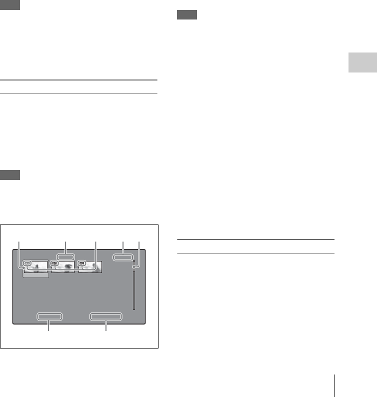
Overview 99
Chapter 5 Operations in GUI Screens
cThumbnail number/total thumbnails
Displays the total number of expanded
thumbnails and the number of the selected
thumbnail.
dScrollbar
See the description in “Clip thumbnail screen” (page
96).
eClip name
Displays the name of the expanded clip. When the
clip has a title, it is displayed as “TITLE00001”
(see page 87). Clip names can be displayed in
European languages when the area of use (see
page 40) is set to “NTSC AREA” or “PAL
AREA”.
Note
To display the clip title, Settings >Display Title in the
Disc Menu needs to be set to On.
fDuration
Displays the time from the selected thumbnail to
the next one.
Chapter thumbnail screen
The sections between essence marks (shot marks
that have been set in clips, and Rec Start essence
marks) are called chapters. The sections between
shot mark and Rec Start essence marks in clips
are called chapters. This screen allows you to
display thumbnails of the chapters in the selected
clip.
Note
Shot marks can be set during recording and playback.
They can be deleted and moved.
Rec Start essence marks are set automatically at the start
of recording. They cannot be deleted or moved.
aSelection frame
See the description in “Clip thumbnail screen” (page
96).
bClip number/total clips
Displays the total number of clips on the disc and
the number of the clip that contains the displayed
chapters.
cS1/S2/RS marks
The “S1”, “S2”, and “RS” marks on the
thumbnails indicate frames where Shot Mark1,
Shot Mark2, and Rec Start essence marks are set.
dChapter number/total chapters
Displays the total number of chapters and the
number of the selected chapter.
Note
The total number of chapters is the total number of
chapters in the specified clip only.
eScrollbar
See the description in “Clip thumbnail screen” (page
96).
fClip name
Displays the name of the clip that contains the
selected frame. When the clip has a title, it is
displayed as “TITLE00001” (see page 87). Clip
names can be displayed in European languages
when the area of use (see page 40) is set to
“NTSC AREA” or “PAL AREA”.
To display the clip title, Settings >Display Title in
the Disc Menu needs to be set to On.
gDuration
Displays the time from the first frame of the
selected chapter to the first frame of the next
chapter.
Essence mark thumbnail screen
This screen displays thumbnails of the specified
essence mark, found by searching all clips on the
disc.
Chapter of Clip 001/024 001/004
TC 00:23:00:25 TC 00:23:02:00 TC 00:23:04:00
CLIP C0001 DUR 0:00:01:05
1425
67
3
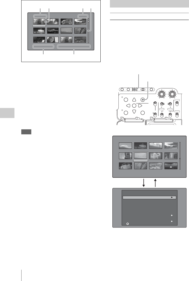
Overview
100
Chapter 5 Operations in GUI Screens
aEssence mark name
Displays the name of the essence mark (Shot
Mark1 here).
bSelection frame
See the description in “Clip thumbnail screen” (page
96).
cEssence mark number/total essence
marks
Displays the total number of essence marks and
the number of the selected essence mark.
Note
The total number of essence marks is the total number of
essence marks that have been set in all clips on the disc.
dScrollbar
See the description in “Clip thumbnail screen” (page
96).
eClip date and time
Displays the date and time when the clip that
contains the selected thumbnail was recorded or
last modified.
fClip name
Displays the name of the clip that contains the
selected frame. When the clip has a title, it is
displayed as “TITLE00001” (see page 87). Clip
names can be displayed in European languages
when the area of use (see page 40) is set to
“NTSC AREA” or “PAL AREA”.
To display the clip title, Settings >Display Title in
the Disc Menu needs to be set to On.
Thumbnail Menu
The Thumbnail Menu displays menu items that
are valid for the currently displayed thumbnail
screen.
To display the Thumbnail Menu
To display the Thumbnail Menu, press the
MENU button with a thumbnail screen displayed.
To return to the original screen, press the MENU
button again, or press the RESET/RETURN
button.
a) Clip thumbnail screen
b) Thumbnail Menu of the clip thumbnail screen
Shot Mark1 001/029
TC 00:23:02:00
TC 00:26:22:11
TC 00:28:35:00
30 NOV 2006 19:55 "Capping literally years of spe..."
TC 00:24:45:25
TC 00:27:19:25
TC 00:28:55:02
TC 00:25:07:01
TC 00:27:51:25
TC 00:29:10:05
TC 00:25:40:24
TC 00:28:06:17
TC 00:29:20:03
12 34
56
Displaying menus
AUTO
FRONT
WIRELESS
THUMBNAIL
SET
S.SEL
SHIFT
ESSENCE
MARK
SUB CLIP
REAR
CH-1
MANUAL
AUDIO SELECT
AUDIO IN
F
W
R
F
W
R
LEVEL
010010
CH-2
CH-3
CH-4
PRESET
F-RUN
REGEN
SET
CLOCK
R-RUN
BRIGHTDISPLAYRESETHOLDDISP SEL
COUNTER RC U-BITEXPAND CHAPTER
MENU
DISC MENU
RETURN
1MENU button
2RESET/RETURN button
Clip:"Navigeting sibiling relati..." 018/036
TC 00:29:19:23
TC 00:30:40:13
TC 00:24:34:27
DATE&TIME 30 NOV 2005 14:14 DUR 0:23:22:26
TC 00:29:38:25
TC 01:01:28:25
TC 00:24:46:22
TC 00:29:50:04
TC 00:09:43:14
TC 00:25:42:08
TC 00:30:25:11
TC 00:24:24:29
TC 00:25:49:07
Clip Information
Select Index Picture
Clip Properties
Add Sub Clips
Delete Clip
Lock/Unlock Clip
Set Clip Flag
Skip Scroll
Thumbnail Search
SHIFT+SET
SHIFT+RESET
SHIFT+STOP
Thumbnail Menu
112
Thumbnail screen a)
Thumbnail Menu b)

Overview 101
Chapter 5 Operations in GUI Screens
Shortcut operations
Shortcut button names are displayed next to the
menu items of commands that have shortcuts (see
page 124).
Note
Shortcuts displayed within parentheses should be used
with all menus closed.
Thumbnail Menu submenus
• The Thumbnail Search Menu contains the basic
commands for thumbnail searches.
• The Thumbnail View Menu contains the basic
commands for moving to other menus.

Overview
102
Chapter 5 Operations in GUI Screens
Disc Menu
The Disc Menu allows you to do the following.
Item Operation/Setting
Load Clip List Load clip list into this unit’s memory.
Save Clip List Save a clip list to the disc under its current name,
overwriting the old contents.
Save Clip list as... Save a clip list to the disc under a new name.
Delete Clip List Delete a clip list from the disc.
Clear Clip List Clear the current clip list from the unit’s memory.
Load Planning
Metadata/Select Drive
Select a media disc or drive and load planning
metadata into this unit’s memory.
Planning Metadata Properties Display the properties of the currently loaded
planning metadata.
Clear Planning Metadata Clear the currently loaded planning metadata from
the unit’s memory.
Lock or Delete All Clips Sub-Item
Lock All Clips Lock all clips.
Unlock All Clips Unlock all clips.
Delete All Clips Delete all clips.
Disc Properties Display the properties of the currently loaded disc.
Or edit the user disc ID, title, and title 2.
Format Disc Format (initialize) the currently loaded disc.
Settings Sub-Item
SET Key on Thumbnail Selects the behavior of the unit when the SET/S.SEL
button or MENU knob is pressed with one thumbnail
selected.
Cue up & Still: Cue up the selected thumbnail.
Cue up & Play: Cue up and play the selected
thumbnail.
Sort Clip List by... Selects a method to sort the clip list.
Name (A-Z): Sort in ascending alphabetic order.
Date (Newest First): Sort by date and time of
creation, newest clip list first.
Sort Planning Metadata
by...
Selects a method to sort the planning metadata.
Name (A-Z): Sort in ascending alphabetic order.
Date (Newest First): Sort by date and time of
creation, newest planning metadata first.
Display Title Selects whether to display clip and clip list titles.
On: Display the title, if it has been set. Otherwise
display the clip name or clip list name.
Off: Do not display the title. Always display the clip
name or clip list name.
Planning Clip Name in
Clip Info. Area
Selects whether to display in the viewfinder the title
contained in a planning metadata file that is loaded
into this unit.
Off: Do not display title.
ASCII Clip Name: Display title in ASCII format.
Clip Name: Display title in UTF-8 format.
Disable “Format Disc” Selects whether to disable the Format Disc command.
Disable: Disable the command.
Enable: Enable the command.
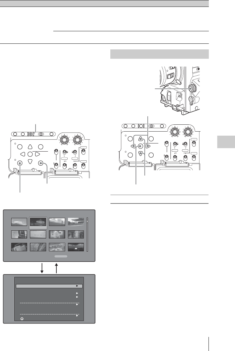
Overview 103
Chapter 5 Operations in GUI Screens
To display the Disc Menu
To display the Disc Menu, press the SUB CLIP/
DISC MENU button with the SHIFT button held
down in one of the following screens.
• Clip thumbnail screen
• Clip list thumbnail screen
• Clip playback screen
• Clip list playback screen
To return to the original screen, press the RESET/
RETURN button.
To select items
Do one of the following to select thumbnails,
menu items, timecode digits, and other items.
• Turn the MENU knob.
• Press the up-, down-, left-, or right-arrow
button.
• Press the PREV or NEXT button.
• With the SHIFT button held down, press the
PREV or NEXT button (to move to the first or
last item).
• Press the PREV button with the F REV button
held down, or press the NEXT button with the F
FWD button held down (to move to the first or
last item).
• With the SHIFT button held down, press the up-
or down-arrow button (to move to the previous
or next page).
• Press the F REV or F FWD button (to move to
the previous or next page).
Select Mouse Pointer
Speed
Selects the speed of the USB mouse pointer used in
the software keyboard screen from among the
following.
5 Fast/4/3 Middle/2/1 Slow
Select USB Keyboard
Language
Selects the language of the USB keyboard used in the
software keyboard screen.
Item Operation/Setting
AUTO
FRONT
WIRELESS
THUMBNAIL
SET
S.SEL
SHIFT
ESSENCE
MARK
SUB CLIP
REAR
CH-1
MANUAL
AUDIO SELECT
AUDIO IN
F
W
R
F
W
R
LEVEL
010010
CH-2
CH-3
CH-4
PRESET
F-RUN
REGEN
SET
CLOCK
R-RUN
BRIGHTDISPLAYRESETHOLDDISP SEL
COUNTER RC U-BITEXPAND CHAPTER
MENU
DISC MENU
RETURN
1SHIFT button
3RESET/RETURN button
2SUB CLIP/DISC MENU button
Load Clip List
Save Clip List
Save Clip List as...
Delete Clip List
Clear Clip List
Load Planning Metadata/Select Drive
Planning Metadata Properties
Clear Planning Metadata
Lock or Delete All Clips
Disc Menu
Clip List:E0001 002/013
TC 00:00:00:00
TC 00:00:28:08
TC 00:00:59:16
DATE&TIME 28 JUL 2006 19:55 TOTAL DUR 00:01:31:16
TC 00:00:04:14
TC 00:00:35:15
TC 00:01:06:18
TC 00:00:12:04
TC 00:00:46:08
TC 00:01:13:11
TC 00:00:20:13
TC 00:00:53:22
TC 00:01:17:27
1+23
Clip list thumbnail screen
GUI screen operations
AUTO
FRONT
WIRELESS
THUMBNAIL
SET
S.SEL
SHIFT
ESSENCE
MARK
SUB CLIP
REAR
CH-1
MANUAL
AUDIO SELECT
AUDIO IN
F
W
R
F
W
R
LEVEL
010010
CH-2
CH-3
CH-4
PRESET
F-RUN
REGEN
SET
CLOCK
R-RUN
BRIGHTDISPLAYRESETHOLDDISP SEL
COUNTER RC U-BITEXPAND CHAPTER
MENU
DISC MENU
RETURN
SET/S.SEL button
MENU knob
Left-/right-arrow buttons
Up-/down-arrow buttons

Thumbnail Operations
104
Chapter 5 Operations in GUI Screens
To select multiple thumbnails
Do one of the following.
• With the SHIFT button held down, turn the
MENU knob.
• With the SHIFT button held down, press the
left- or right-arrow button.
To return to the previous screen
Press the RESET/RETURN button.
To move from a menu level to the next
lower or higher menu level
For a menu item displayed together with a B or b
mark, you can move to the next lower or higher
menu level by pressing the right- or left-arrow
button.
To scroll hidden parts of the string into
view
When a B or b mark is displayed for an item, you
can press the left or right arrow button to scroll
the display by one character for each press.
The up and down arrow buttons scroll the
beginning and end of the string into view.
To increment and decrement numbers
Do one of the following.
• Press the up- or down-arrow button.
• Turn the MENU knob.
To confirm selections
Press the SET/S.SEL button or the MENU knob.
You can use thumbnail screens to display clip
information and to find, protect, and delete clips.
The thumbnails provide visual confirmation of
these and other operations.
The thumbnail selection frame (see page 97)
indicates the currently selected thumbnail.
To move the thumbnail selection frame
Turn the MENU knob, or press the arrow buttons.
To skip quickly through thumbnails (Skip
Scroll function)
When you have a large number of thumbnails,
like in expand thumbnail screen, you can use the
Skip Scroll function to skip through them quickly.
See page 103 for more information about operations
in thumbnail screens.
1In the screens like clip thumbnail screen
or expand thumbnail screen, display the
Thumbnail Menu.
2Select Skip Scroll, and then press the
SET/S.SEL button or the MENU knob.
A small popup window appears on the
scrollbar to indicate the position of the
currently selected thumbnail within the set of
all thumbnails.
Thumbnail Operations
Selecting thumbnails
"Seashore"
DUR
Expand 007/235
DUR 0:00:00:01
DUR 0:00:00:01
DUR 0:00:00:01
DUR 0:00:00:01
DUR 0:00:00:01
DUR 0:00:00:01
DUR 0:00:00:01
DUR 0:00:00:01
DUR 0:00:00:01
DUR 0:00:00:01
DUR 0:00:00:01
CLIP
0:00:00:01
DUR 0:00:00:01
007/235
Skip Scroll
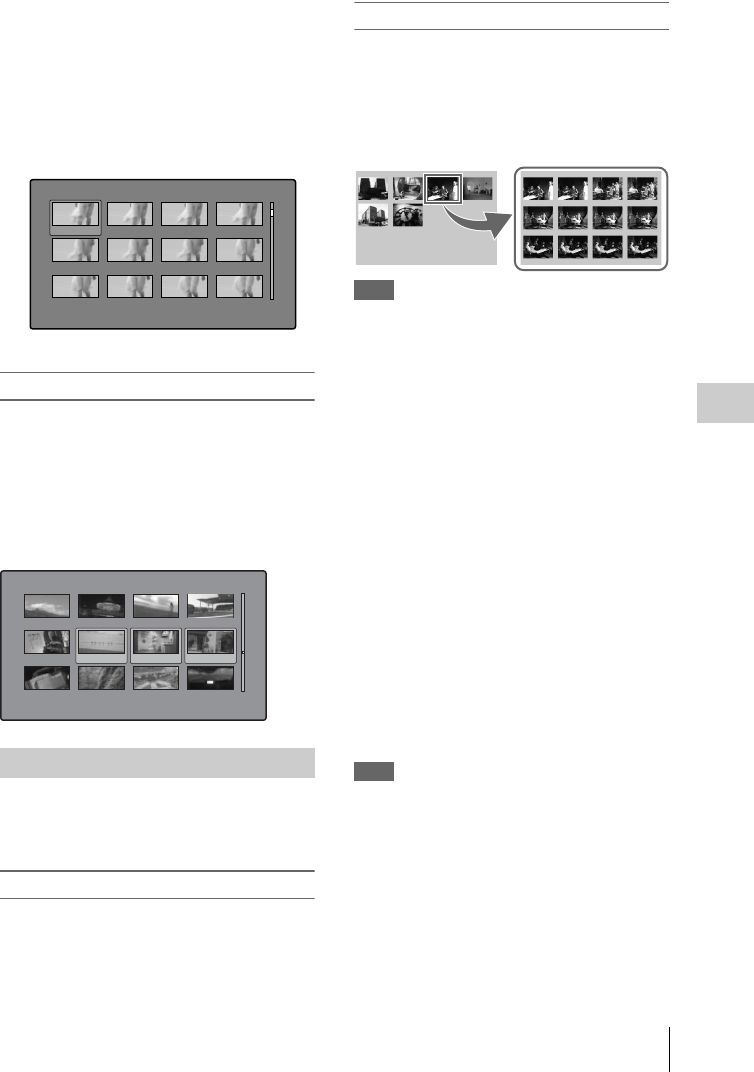
Thumbnail Operations 105
Chapter 5 Operations in GUI Screens
3Turn the MENU knob, or press the left-
or right-arrow button.
The current position moves by an amount
equal to 1/10 of the total number of
thumbnails.
4Press the SET/S.SEL button or the
MENU knob at the new position.
The thumbnail at the position indicated in the
small popup window appears in a thumbnail
screen like the following 1).
1) Expand thumbnail screen
To select multiple thumbnails
Move the selection frame to the first thumbnail
that you want to select. Then, with the SHIFT
button held down, Turn the MENU knob, or press
the right-arrow button.
To cancel the multiple selection, move the
selection frame without the SHIFT button held
down.
By using the thumbnails that appear in the various
thumbnail screens, you can easily cue up and play
clips and sub clips.
Using thumbnails to find clips
The clip thumbnail screen displays thumbnails of
all clips recorded on the disc. You can use this
screen to cue up the selected clip and to carry out
playback (see page 107).
See “Selecting thumbnails” (page 104) for more
information.
Using the expand function to find scenes
The expand function allows you to divide a
selected clip into equally sized blocks, and to
display thumbnails of the first frame in each
block. This is a quick and efficient way to review
the selected clip and search for target scenes. You
can specify 12, 144, or 1728 divisions.
Note
The maximum number of blocks may be other than 1728
when the recorded duration of the clip is short. In this
case, the frame interval of expanded thumbnails is fixed
at 1 frame. This allows you to view expanded thumbnails
at equal intervals.
See page 103 for more information about thumbnail
screen operations.
1In the clip thumbnail screen, select the
thumbnail of the clip that contains the
scene you want to find.
2Press the DISP SEL/EXPAND button.
The selected clip is divided into 12 blocks,
and a list appears in the expand thumbnail
screen (see page 98) with the first frame of
each block displayed as a thumbnail.
3Select the thumbnail that you want to
expand further.
4Repeat steps 2 and 3 up to 2 times, as
required.
Note
Thumbnails cannot be further expanded when they
already have the minimum duration (1 frame).
To return to the previous expansion level
Press the DISP SEL/EXPAND button with the
SHIFT button held down.
To display the expand thumbnail screen of the
previous or next clip
With the expand thumbnail screen still active,
press the PREV button or the NEXT button.
Searching with thumbnails
"Seashore" DUR
Expand 007/235
DUR 0:00:00:01
DUR 0:00:00:01
DUR 0:00:00:01
DUR 0:00:00:01
DUR 0:00:00:01
DUR 0:00:00:01
DUR 0:00:00:01
DUR 0:00:00:01
DUR 0:00:00:01
DUR 0:00:00:01
DUR 0:00:00:01
CLIP 0:00:00:01
DUR 0:00:00:01
Clip:"Navigating sibling relati..." 018/036
TC 00:29:19:23
TC 00:30:40:13
TC 00:24:34:27
DATE&TIME
30 NOV 2005 14:14
DUR
0:23:22:26
TC 00:29:38:25
TC 01:01:28:25
TC 00:24:46:22
TC 00:29:50:04
TC 00:09:43:14
TC 00:25:42:08
TC 00:30:25:11
TC 00:24:24:29
TC 00:25:49:07
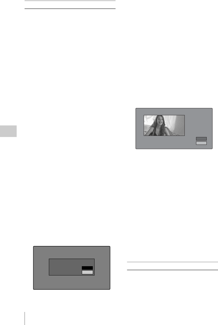
Thumbnail Operations
106
Chapter 5 Operations in GUI Screens
Using the chapter function to find scenes
Sections between shot marks and Rec Start are
called chapters.
Rec Start essence marks are set automatically at
the start of recording, but shot marks can be set at
any scene during recording or playback.
The chapter function allows you to display
thumbnails of the chapters in a clip.
See “Recording essence marks” (page 80) for more
information.
See page 103 for more information about thumbnail
screen operations.
1In the clip thumbnail screen, select the
thumbnail of a clip with chapters set.
The “S” mark appears on the thumbnails of
clips with chapters set.
2Press the HOLD/CHAPTER button.
The chapter thumbnail screen (see page 99)
appears, with thumbnails of the frames where
chapters are set.
The “S1”, “S2”, and “RS” marks on the
thumbnails indicate frames where Shot
Mark1, Shot Mark2, and Rec Start essence
marks are set.
To delete the shot mark at a chapter position
You can delete the shot mark (Shot Mark1 or Shot
Mark2) at the chapter position in the chapter
thumbnail screen. (Rec Satrt essence marks
cannot be deleted.)
1In the chapter thumbnail screen, select
the thumbnail for the frame whose shot
mark you want to delete.
2Display the Thumbnail Menu.
3Select Delete Shot Mark.
A message appears asking if you are sure that
you want to delete the shot mark.
4Select OK to delete the mark, or Cancel
to cancel the deletion, and then press the
SET/S.SEL button or the MENU knob.
To adjust the position of shot marks at chapter
positions
You can use the chapter thumbnail screen to
adjust the position of shot marks (Shot Mark1 and
Shot Mark2) at chapter positions. (The positions
of Rec Start essence marks cannot be adjusted.)
1In the chapter thumbnail screen, select
the thumbnail of the shot mark whose
position you want to adjust.
2Display the Thumbnail Menu.
3Select Move Shot Mark.
The Move Shot Mark screen is displayed.
You can perform playback and searches in
this screen.
4Use the PLAY/PAUSE button or F
REV/F FWD buttons to display the
frame you want.
You can also perform jog playback by
turning the MENU knob.
5Select OK, and then press the SET/
S.SEL button or the MENU knob.
To display the chapter thumbnail screen of the
previous or next clip with chapters
With the chapter thumbnail screen still active,
press the PREV button or the NEXT button.
The unit searches in the reverse or forward
direction for the next clip with chapters,
beginning with the previous or next clip.
Using essence marks to find scenes
See page 103 for more information about thumbnail
screen operations.
1In the clip playback screen or the clip
thumbnail screen, press the
Clip List:E0001 002/013
TC 00:00:00:00
TC 00:00:28:08
TC 00:00:59:16
DATE&TIME 28 JUL 2006 19:55 TOTAL DUR 00:01:31:16
TC 00:00:04:14
TC 00:00:35:15
TC 00:01:06:18
TC 00:00:12:04
TC 00:00:46:08
TC 00:01:13:11
TC 00:00:20:13
TC 00:00:53:22
TC 00:01:17:27
Cancel
OK
Delete Shot Mark
Delete 002?
Move Shot Mark : ShotMark2 0002/0002
OK
Cancel
TCR 00:28:23:14
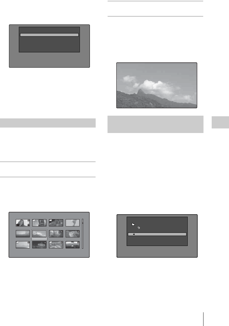
Thumbnail Operations 107
Chapter 5 Operations in GUI Screens
THUMBNAIL/ESSENCE MARK
button with the SHIFT button held
down.
The Select Essence Mark screen appears.
The names of essence marks that are not
recorded on the disc are displayed in gray.
2Select the essence mark that you want,
and then press the SET/S.SEL button or
the MENU knob.
The essence mark thumbnail screen (see
page 99) displays a list of frames where the
selected essence mark is set.
After finding a clip with one of the methods
explained in the previous section, “Searching
with thumbnails” (page 105), you can cue up and
play the clip that you have found.
To search for a thumbnail position and
cue it up
See page 103 for more information about GUI screen
operations.
1Select the thumbnail that you want to
cue up.
2Press the SET/S.SEL button or the
MENU knob.
To play clips with the SET/S.SEL button
In the Disc Menu, set Settings >SET Key on
Thumbnail to “Cue up & Play”. Play begins from
the selected frame when you press the SET/S.SEL
button, in the same way as when you press the
PLAY/PAUSE button.
To search for a thumbnail position and
play from there
See page 103 for more information about GUI screen
operations.
1Select the thumbnail that you want to
play.
2Press the PLAY/PAUSE button.
You can select the information to be displayed at
the bottom of the thumbnails in thumbnail
screens.
See page 103 for more information about thumbnail
screen operations.
1Display the Thumbnail Menu in the clip
thumbnail screen.
2Select Clip Information.
A window appears in which you can select
the information to display.
3Select the items that you want to
display.
Return to Upper Menu: Returns to the
Thumbnail Menu
Date: Date and time of creation, or date and
time of the more recent modification
Playing the scene you have found
Shot Mark1
Shot Mark2
Rec Start
Cut
Others
Select Essence Mark
Clip:C0010 010/041
TC 00:23:00:25
TC 00:25:49:23
TC 00:28:06:09
DATE&TIME 30 NOV 2005 13:40 DUR 0:00:04:14
TC 00:23:40:07
TC 00:26:22:10
TC 00:28:22:02
TC 00:24:45:11
TC 00:27:19:04
TC 00:23:34:18
TC 00:25:06:14
TC 00:27:51:09
TC 00:23:54:22
OK
Selecting the information
displayed on thumbnails
Clip Information
Return to Upper Menu
Date
Time Code
Duration
Sequence Number
Thumbnail Menu
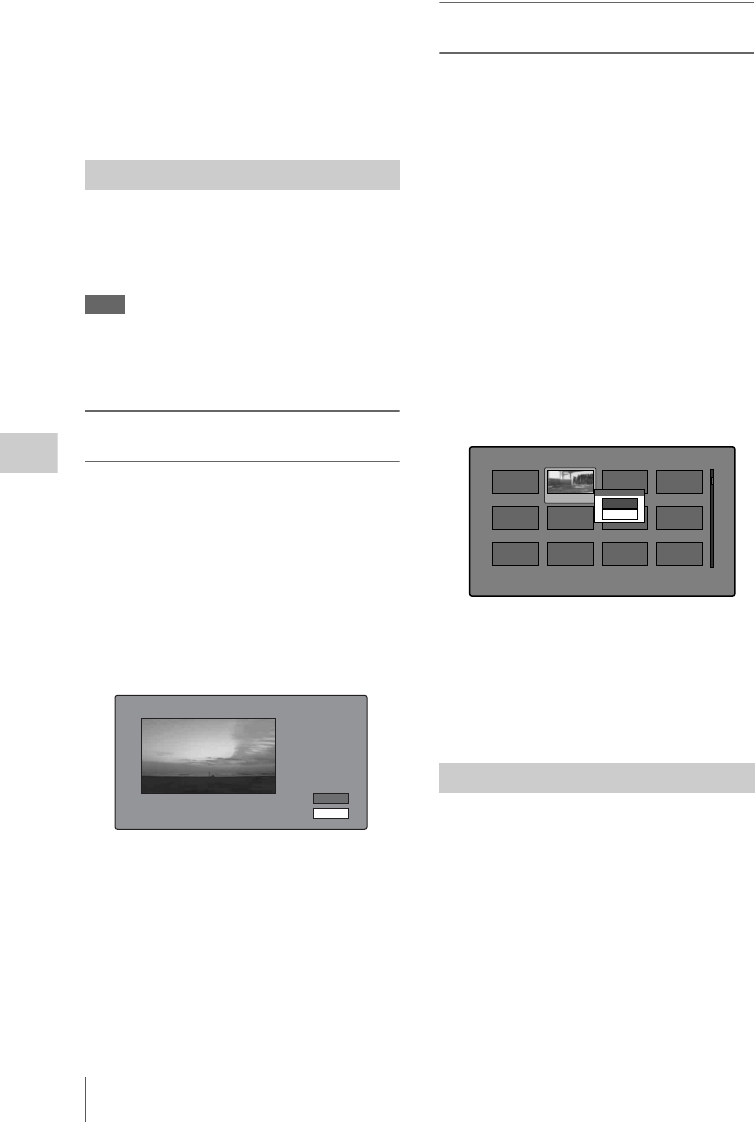
Thumbnail Operations
108
Chapter 5 Operations in GUI Screens
Time Code: Timecode of first frame
Duration: Playback time
Sequence Number: Thumbnail sequence
number
The selected information will appear at the
bottom of the thumbnails when you display a
thumbnail screen.
The clip thumbnail screen displays thumbnails as
index pictures for clips. Normally the index
picture is the first frame in a clip, but you can set
any frame in the clip as the index picture.
Note
You can only change index pictures from the clip
thumbnail screen. The thumbnails shown in the clip list
thumbnail screen, the expand thumbnail screen, and the
chapter thumbnail screen cannot be changed.
To select a clip index picture while
viewing the video
See page 103 for more information about thumbnail
screen operations.
1In the clip thumbnail screen, select the
thumbnail of the clip whose index
picture you want to change.
2Display the Thumbnail Menu.
3Select Select Index Picture.
Select Index screen appears.
You can play and search with this screen.
4Use the PLAY/PAUSE button or F
REV/F FWD buttons to display the
frame you want.
You can also perform a jog operation by
turning the MENU knob.
5Press the up-arrow button to select OK,
and then press the SET/S.SEL button or
the MENU knob.
To select index pictures by using the
expand and chapter functions
After using the expand function (see page 105) or
chapter function (see page 106) to find a frame,
you can set that frame as the index picture of the
clip.
The following example explains how to do so
from the expand thumbnail screen.
See page 103 for more information about thumbnail
screen operations.
1In the expand thumbnail screen, select
the thumbnail to set as the index
picture.
2Display the Thumbnail Menu.
3Select Set Index Picture.
A message appears asking you to confirm
that you want to set the current frame as the
index picture.
4Select OK, and then press the SET/
S.SEL button or the MENU knob.
After pressing the RESET/RETURN button
to return to the clip thumbnail screen, check
to make sure that the newly selected frame is
displayed as the index picture.
You can check clip properties such as the title,
timecode, duration, date and time of creation, and
date and time of the more recent modification.
See page 103 for more information about thumbnail
screen operations.
1Display the Thumbnail Menu in the clip
thumbnail screen.
2Select Clip Properties.
The Clip Properties screen appears.
Changing clip index pictures
Select Index:"Navigating sibling relati..." 018/036
TCR
01:09:16:13
OK
Cancel
Checking clip properties
Expand 001/012
TC 00:01:35:17
TC 00:01:37:11
TC 00:01:39:06
TC 00:01:37:24
TC 00:01:38:19
TC 00:01:36:14
TC 00:01:38:08
TC 00:01:40:02
TC 00:01:36:27
TC 00:01:38:22
TC 00:01:40:16
CLIP Ten e DUR 0:00:00:13
TC 00:01:38:00 Set Index Picture
OK
Cancel
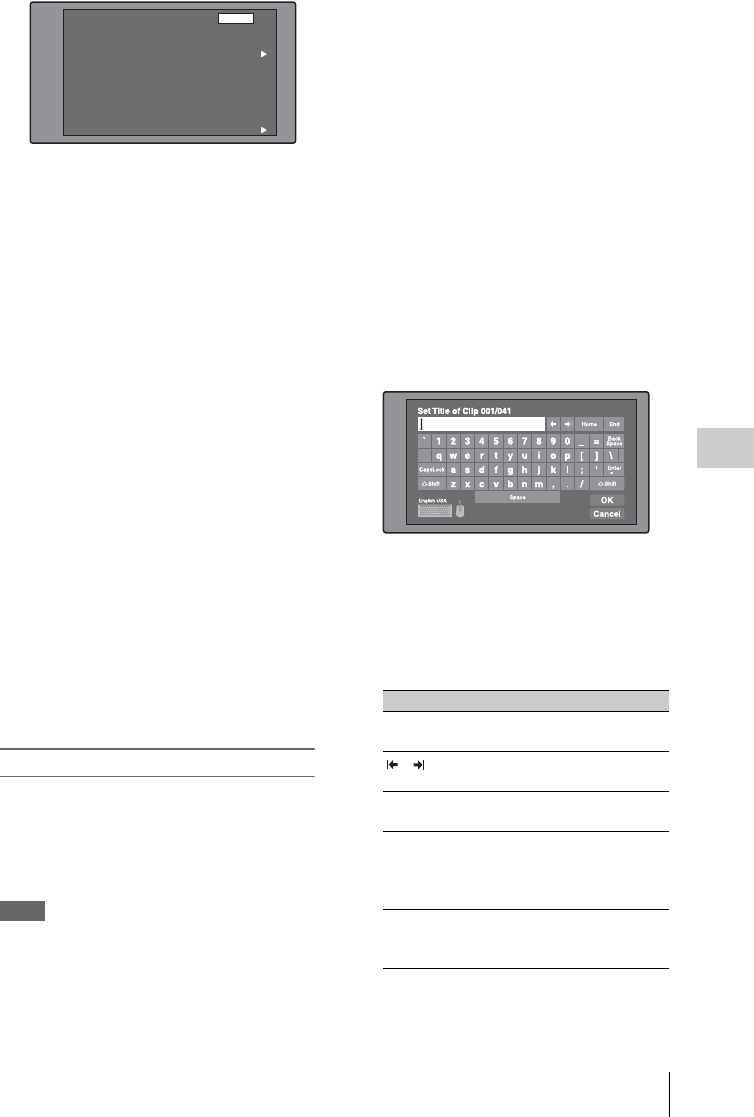
Thumbnail Operations 109
Chapter 5 Operations in GUI Screens
Clip No.: Clip number/total number of clips
Name: Clip name 1)
Title: Title
Title2: Title 2 1)
TC: Timecode of first frame
DUR: Recording time
Created: Date and time of creation
Modified: Date and time of most recent
modification
Rec Device: Name of device that created clip
(product number)
1) Titles can be displayed in European languages
when the area of use (see page 40) is set to
“NTSC AREA” or “PAL AREA”.
To scroll hidden parts of the string into
view
When a B or b mark is displayed for an item,
you can press the left or right arrow button to
scroll the display by one character for each
press.
The up and down arrow buttons scroll the
beginning and end of the string into view.
To display the properties of the previous
or the next clip
Press the PREV button or the NEXT button.
To return to the clip thumbnail screen
Press the SET/S.SEL button or the MENU
knob.
To edit clip information
You can edit the name, 1) title, and title 2 of a clip
by using a software keyboard.
1) The NAMING FORM item on the FILE NAMING
page of the OPERATION menu must be set to FREE
(see page 137).
Notes
• The only characters that can be entered are the
alphanumeric characters and symbols that appear on
the software keyboard, and European language
characters displayed on the keyboards illustrated in
“List of Supported USB Keyboards” (page 231).
Japanese kanji cannot be entered.
• Names and titles must be within the specified character
length limits.
• Some symbols cannot be used in clip names. The keys
for those symbols are disabled when you are editing a
clip name.
See page 103 for more information about GUI
screen operations.
1In the Clip Properties screen, turn the
MENU knob to select the item you want
to edit (Name, Title 1), or Title2).
1) Only ASCII characters can be used for Title.
2Press the SET/S.SEL button or the
MENU knob.
An input screen appears for the selected item.
(An English keyboard appears if the area of
use setting NTSC AREA or PAL AREA. A
Japanese keyboard appears if the area of use
setting is NTSC(J) AREA.)
3Edit the string in the edit box.
To enter characters
Use the arrow buttons or turn the MENU
knob to select a key, and then press the SET/
S.SEL button or the MENU knob.
Functions of special keys
Clip No.
Name
Title
Title2
TC
DUR
Created
Modified
Rec Device
001/035
TèlèvisionLCD
Capping Literally years of spe...
Rétroprpjecteurs BRAVIA
00:23:00:25
0:00:09:22
30 NOV 2005 13:35±00:00
20 MAY 2006 15:02±00:00
PDW-700(SN-10001)
Clip Properties OK
Horizontal Scroll
Key Function
<, ,Move the cursor one character
forward or back.
, Move the cursor to Home or
End position.
Back Space Deletes the character in front
of the cursor.
CapsLock Turns the Shift key on
permanently (until pressed
again), and enables input of
capital letters and symbols.
FShift Enables input of capital
letters and symbols. Turns off
after entry of one character.
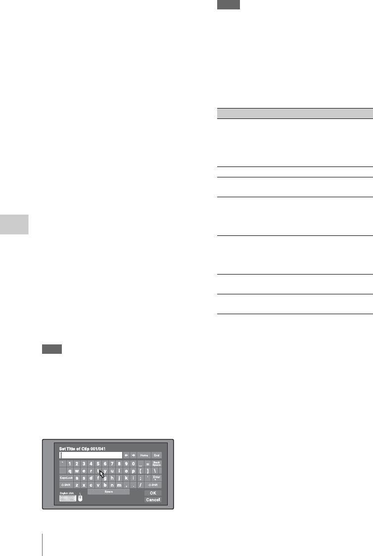
Thumbnail Operations
110
Chapter 5 Operations in GUI Screens
4Select “OK”, and then press the SET/
S.SEL button or the MENU knob.
You return to the Clip Properties screen, and
the results of the editing are reflected in the
clip information.
To enter text using a USB keyboard or USB
mouse
You can connect a Windows USB keyboard or a
Windows USB mouse to the USB connector (see
page 28) 1), and use them together with the
software keyboard to enter text.
Connect the Japanese keyboard if the area of use
has been set to NTSC(J) AREA.
Connect a European language keyboard if the
area of use has been set to NTSC AREA or PAL
AREA.
1) Some USB keyboards or USB mice may not be used.
In this case, the message “Unknown USB” appears.
To change the keyboard language: In the Disc
Menu, select Settings >Select USB
Keyboard Language and then select the
desired keyboard from among the following.
• English [United Kingdom]
• English [United States]
• French [France]
• German [Germany]
• Italian [Italy]
• Polish (Programmers) [Poland]
• Russian [Russia]
• Spanish [Spain]
See “List of Supported USB Keyboards” (page 231)
for the characters that can be entered on the various
language keyboards.
Note
The keyboard language cannot be changed when the area
of use is set to NTSC(J) AREA.
The keyboard icon on the software keyboard is
highlighted when a USB keyboard has been
recognized and enabled for use with this unit, and
the mouse icon is highlighted and a mouse pointer
appears when a USB mouse has been enabled.
Notes
• Use the proper keyboard for the area of use. Some
characters may not be entered correctly if you use a
keyboard designed for use in another area.
• It is not possible to enter Japanese, even on a Japanese
keyboard.
USB keyboard special functions keys
In addition to the special function keys of the
software keyboard, you can use the following
special function keys on a USB keyboard.
USB mouse functions
You can use the mouse to move the cursor on the
software keyboard. You can also left click on a
key to enter the character for that key.
To change the speed of the mouse pointer: In
the Disc Menu, select Settings >Select
Mouse Pointer Speed and then select the
desired speed. Adjust according to the
selected mouse.
To exit the software keyboard from a USB
keyboard
1With the cursor in an edit box, press the
Enter key or the Esc key to move the
focus to “Cancel”.
Key Function
R, rWhen the cursor is in an edit box:
Move the cursor to the start or end.
When “OK” or “Cancel” has the
focus: Moves the focus between
“OK” and “Cancel”.
Delete Deletes the character after the cursor.
Shift + T,
Shift + t
Selects the string before or after the
cursor.
Ctrl + C,
X, V, A
Ctrl + C: Copies the selected string.
Ctrl + X: Cuts the selected string.
Ctrl + V: Pastes a copied or cut string.
Ctrl + A: Selects the entire string.
Enter When the cursor is in an edit box:
Moves the focus to “Cancel”.
When “OK” or “Cancel” has the
focus: Exits the software keyboard.
Esc When the cursor is in an edit box,
moves the focus to “Cancel”.
Tab Moves the focus between “OK” and
“Cancel”.

Thumbnail Operations 111
Chapter 5 Operations in GUI Screens
2Do one of the following.
To confirm the edit and then exit the
software keyboard: Press the Tab key
to move to “OK”, and then press the
Enter key.
To discard the edit and then exit the
software keyboard: While “Cancel” is
selected, press the Enter key.
To continue editing: Press any key except
the Enter key, the Esc key, and the Tab
key.
You can set three types of clip flags (OK/NG/KP
(KEEP)) during recording or playback. Setting
these flags in each clip that you record makes it
easy for editors and other colleagues to find and
select the clips they need.
See page 103 for more information about thumbnail
screen operations.
1In the clip thumbnail screen, select the
thumbnail of the clip where you want to
set a flag.
2Display the Thumbnail Menu.
3Select “Set Clip Flag”.
The clip flag setting screen appears.
4Select the clip flag that you want to set
(OK/NG/KP (KEEP)).
A clip flag icon (see page 97) appears for
clips that have clip flags set.
To clear clip flags
Carry out steps 1 to 3, selecting a clip that has a
flag set, and then select “none” in step 4.
You can also use switches to set and clear clip flags.
For details, see “Setting clip flags with switches”
(page 80).
In a clip thumbnail screen, you can lock the
selected clips so that they cannot be deleted or
altered.
Locking prevents the following operations on
clips.
•Deletion
• Renaming by FTP
• Changing the index picture
• Adding and deleting shot marks
• Setting and clearing clip flags
Notes
• Locked clips are deleted along with other clips when a
disc is formatted.
• Clips cannot be locked or unlocked when the Write
Inhibit tab of the disc is set to the recording disabled
position.
To lock clips
See page 103 for more information about thumbnail
screen operations.
1In the clip thumbnail screen, select the
thumbnails of the clips that you want to
lock.
2Display the Thumbnail Menu.
3Select Lock/Unlock Clip.
4Press the SET/S.SEL button or the
MENU knob.
A lock icon (see page 98) appears on the
thumbnail of the locked clips.
In step 1, you can also perform a shortcut
operation by pressing the STOP button with the
SHIFT button held down.
To lock all clips
1Display the Disc Menu.
2Select Lock or Delete All Clips, and then
select Lock All Clips.
A message appears asking you to confirm
locking all clips.
3Select OK to lock all clips or Cancel to
cancel it, and then press the SET/S.SEL
button or the MENU knob.
Setting clip flags
Thumbnail Menu
Set Clip Flag
Return to Upper Menu
OK
NG
KP (KEEP)
none
Locking (write-protecting) clips

Thumbnail Operations
112
Chapter 5 Operations in GUI Screens
To unlock a specific clip
See page 103 for more information about thumbnail
screen operations.
1In the clip thumbnail screen, select the
thumbnail of the clip that you want to
unlock.
2Display the Thumbnail Menu.
3Select Lock/Unlock Clip.
A message appears asking you to confirm the
unlocking.
4Select OK, and then press the SET/
S.SEL button or the MENU knob.
In step 1, you can also perform a shortcut
operation by pressing the STOP button with the
SHIFT button held down.
To unlock all clips
1Display the Disc Menu.
2Select Lock or Delete All Clips, and then
select Unlock All Clips.
A message appears asking you to confirm
that you want to unlock all clips.
3Select OK to execute the unlock, or
Cancel to cancel it, and then press the
SET/S.SEL button or the MENU knob.
You can delete clips while checking their
contents.
Notes
• Clips cannot be deleted when the Write Inhibit tab of
the disc is set to the recording disabled position.
• Locked clips cannot be deleted.
• If a deletion target clips is referenced by clip lists on
the disc, all of those clip lists are deleted as well.
• If a deletion target clip is referenced in the current clip
list, only those referencing sub clips are deleted at the
same time as the deletion target clip.
See page 103 for more information about thumbnail
screen operations.
1In the clip thumbnail screen, select the
thumbnail of the clip that you want to
delete.
2Display the Thumbnail Menu.
3Select Delete Clip.
A window appears asking you to confirm the
deletion. The window displays thumbnails of
four frames from the target clip (the first
frame, two intermediate frames, and the last
frame), along with the name, title, date of
creation, and duration of the clip.
One of the following messages also appears,
depending on whether the clip is referenced
in a clip list.
When the clip is not referenced in a clip
list: “Delete Clip”
When the clip is referenced in a clip list:
“Delete Clip & Clip List” (All clip lists
that reference the target clip are deleted
along with the clip.)
4Select OK, and then press the SET/
S.SEL button or the MENU knob.
The selected clip is deleted, and you return to
the clip thumbnail screen.
In step 1, you can also perform a shortcut
operation by pressing the RESET/RETURN
button with the SHIFT button held down.
To delete all clips
1Display the Disc Menu.
Deleting clips
Clip List:E0001 002/013
TC 00:00:00:00
TC 00:00:28:08
TC 00:00:59:16
DATE&TIME
28 JUL 2006 19:55
TOTAL DUR
00:01:31:16
TC 00:00:04:14
TC 00:00:35:15
TC 00:01:06:18
TC 00:00:12:04
TC 00:00:46:08
TC 00:01:13:11
TC 00:00:20:13
TC 00:00:53:22
TC 00:01:17:27
Cancel
OK
Unlock Clip
Unlock this Clip?
C0004
Delete Clip & Clip List 022/036
TC 00:25:29:09
INDEX
TC 00:25:30:00
MIDDLE1
TC 00:25:30:22
MIDDLE2
TC 00:25:31:13
END
Title SCENE-00126
Date 2005 DEC 01 14:55
Name C0023
Dur 0:00:02:05
On Clip List
OK
Cancel

Scene Selection (Clip List Editing) 113
Chapter 5 Operations in GUI Screens
2Select Lock or Delete All Clips, and then
select Delete All Clips.
A message appears asking you to confirm
that you want to delete all clips.
3Select OK to execute the deletion, or
Cancel to cancel it, and then press the
SET/S.SEL button or the MENU knob.
Note
Locked clips cannot be deleted. Scene selection is a function which allows you to
select material (clips) from the material recorded
on a disc and perform cut editing. You can do this
by operating on this unit only.
• Scene selection is a convenient way to perform
cut editing in the field and in other offline
situations.
• In scene selection you create a clip list (editing
data). Since the material itself is not affected,
you can repeat this any number of times.
• You can play back the edit list created by scene
selection on this unit.
• In scene selection you can add whole clips or
add parts of a clip. You can add scenes using
chapters, change the playback sequence, and
amend or delete In and Out points. All of these
operations can be carried out easily on this unit.
• Clip lists (editing data) created with the scene
selection function can be used on XPRI and
other full-feature nonlinear editing systems.
Clips
Material recorded with this unit is managed in
units called clips. A clip contains the material
from a recording start point to a recording end
point.
Clips have numbers beginning with C, for
example C0001.
You can also assign titles to your clips and use the
titles to manage them, instead of the clip numbers.
For more information, see “Assigning user-defined
clip titles automatically” (page 87).
Scene Selection (Clip
List Editing)
What is scene selection?
Recording
start point
of clip 2
Recording
end point
of clip 2
Clip 1
(C0001) Clip 2
(C0002)
Clip 3
(C0003) Clip 4
(C0004)
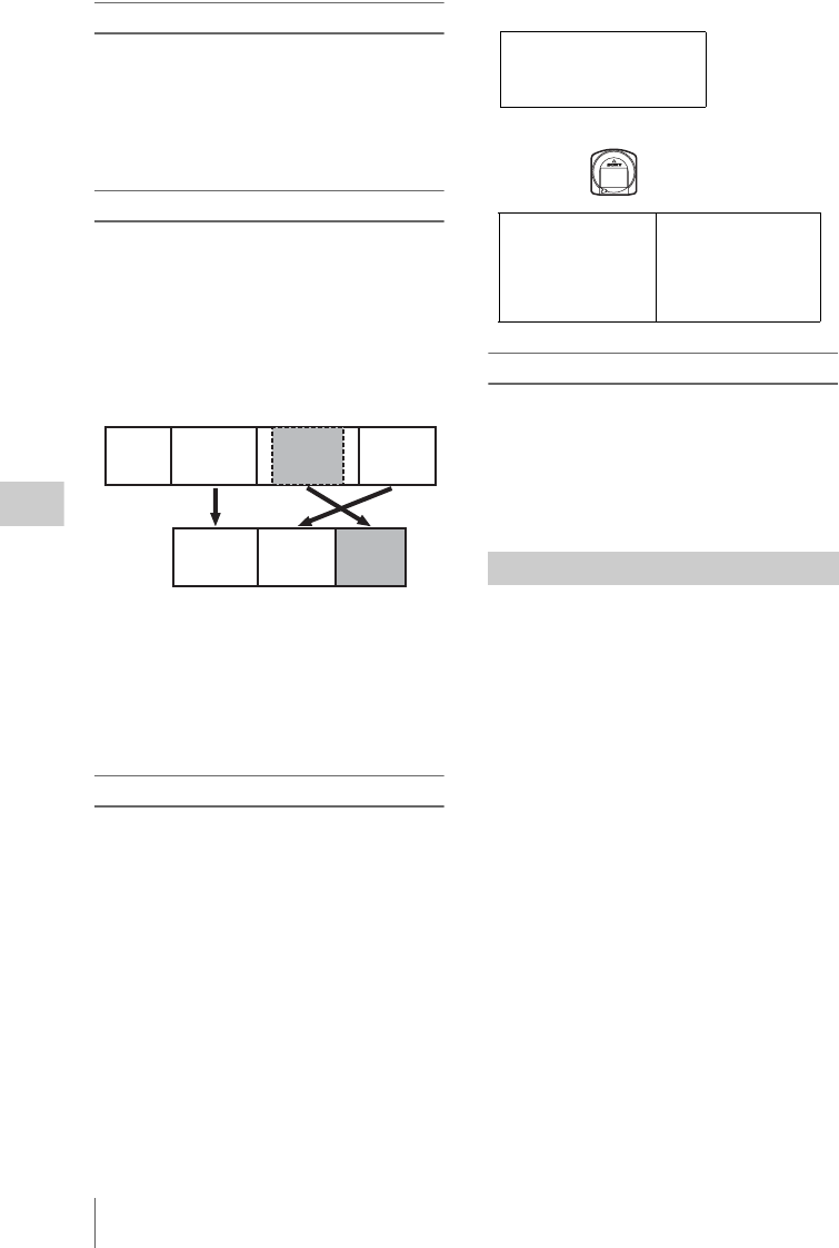
Scene Selection (Clip List Editing)
114
Chapter 5 Operations in GUI Screens
Clip lists
You can use the scene selection function to select
clips from the clips saved on a disc and create a
cut edit list called a “clip list”.
Clip lists have numbers beginning with E, for
example E0001. Up to 99 clip lists can be saved
on a disc.
Sub clips (clips in clip lists)
Clips (or parts of clips) that have been added to a
clip list are called “sub clips”. Sub clips are
virtual editing data that specify ranges in the
original clips. You can use them without
modifying the original data.
The following figure illustrates the relation
between clips and sub clips.
In the above example, the whole of clip 2 has been
added as sub clip 1, and the whole of clip 4 has
been added as sub clip 2.
Sub clip 3 is part of clip 3. Therefore, when clip
list E0001 is played back, clip 4 is played after
clip 2, and then the part of clip 3 shown in gray
color is played.
Clip list editing (current clip list)
To edit a clip list, you need to load the clip list
from the disc into the unit's internal memory.
The clip list which is currently loaded into the
unit memory is called the “current clip list”.
The current clip list is always the target of sub clip
creation and editing. Clip list playback also uses
the current clip list.
After creating and editing a clip list, you need to
save it to disc.
Clip list playback
Clips and clip lists are saved together on a disc.
To play a clip list, insert a disc into the unit, load
the clip list that you want to play, and press the
PLAY/PAUSE button.
Clips are played according to the data in the clip
list.
The following table lists the steps in the creation
and editing of clip lists with the scene selection
function. To create a clip list, you always need to
carry out the steps inside the heavy lines. Other
steps can be carried out as required.
Clip 1
(C0001) Clip 2
(C0002) Clip 3
(C0003)
Clip list
(E0001) Sub clip 1 Sub clip 2
Sub clip 3
Clip 4
(C0004)
Clips on disc
Creating and editing clip lists
Current clip list can be edited
(adding, deleting, and
reordering sub clips)
Unit memory
tClip list
playback and
thumbnail
display
SAVE m MLOAD
Disc
C0001 (Clip 1)
C0002 (Clip 2)
C0003 (Clip 3)
:
:
E0001 (Clip list 1)
E0002 (Clip list 2)
E0003 (Clip list 3)
:
:
E0099 (Clip list 99)
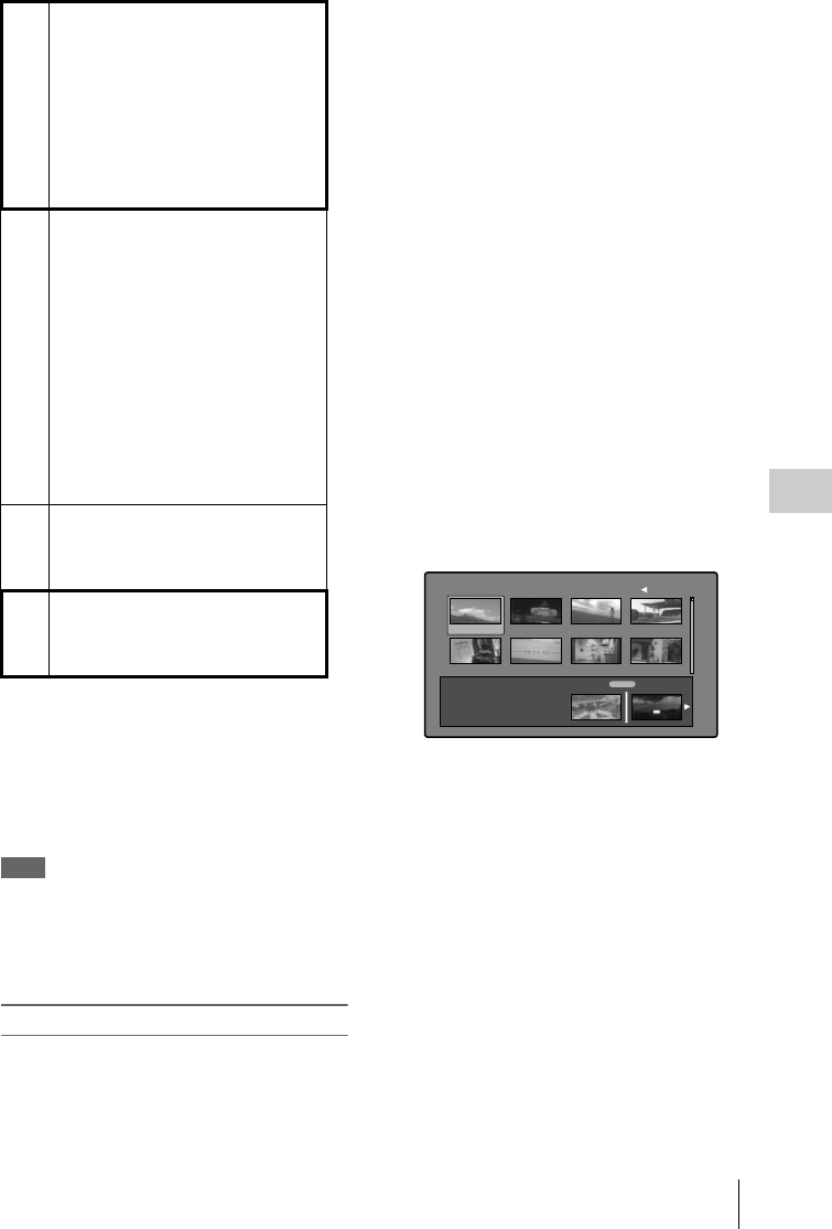
Scene Selection (Clip List Editing) 115
Chapter 5 Operations in GUI Screens
To reedit clip lists on the disc
Use the Load Clip List command to load the clip
lists you want to edit, and perform the steps 2 to
4 in the previous section.
You can also delete clip lists on the disc.
For details, see “Managing clip lists” (page 119).
Note
Clip lists can be created and edited even when the Write
Inhibit tab of the disc is set to recording disabled.
However, if you need to save the clip list, set Write
Inhibit tab to enable recording before you create or edit
the clip list.
To add sub clips
You can add sub clips to clip lists from with the
clip thumbnail screen or the clip list thumbnail
screen. However, you must use the clip list
thumbnail screen to edit clip lists.
Adding sub clips from the clip thumbnail screen
The following procedure explains operations in
the clip thumbnail screen. You can proceed in the
same way in the expand thumbnail screen and the
chapter thumbnail screen. Expanded blocks are
added as sub clips in the expand thumbnail
screen, and chapters are added as sub clips in the
chapter thumbnail screen.
See page 103 for more information about thumbnail
screen operations.
1In the clip thumbnail screen, select the
clip that you want to add as a sub clip
(multiple selections possible).
2Display the Thumbnail Menu.
3Select Add Sub Clips, and then press the
SET/S.SEL button or the MENU knob.
The Add Sub Clip screen appears.
The clip(s) selected in step 1 appear in the
upper part of this screen, and the clip list
appears in the lower Scene Selection
window. The I cursor in the Scene Selection
window indicates the location where the
currently selected sub clip(s) will be inserted.
To display the total duration after
addition of the selected clip
Press the SHIFT button.
4In the Scene Selection window, move
the I cursor to the location where you
want to insert the clip. (The existing
thumbnails arrange themselves to the
left and right of the I cursor.)
5Press the SET/S.SEL button or the
MENU knob.
The selected clip is inserted as a subclip and
a “+” mark appears on the thumbnail in the
Scene Selection window.
To check the addition results
Move the cursor.
1Add sub clips: Use the Add Sub Clips
command to add the clips you want to
use to a clip list. You can add up to
300 sub clips to one clip list.This
operation can be carried out in the
following thumbnail screens.
• Clip thumbnail screen
• Expand thumbnail screen
• Chapter thumbnail screen
• Clip list thumbnail screen
2Change the sub clip order: Use the
Move Sub Clips command to change
the order of sub clips in a clip list.
Delete sub clips: Use the Delete Sub
Clips command to delete specified
sub clips from a clip list.
Trim sub clips: Use the Trim Sub Clip
command to adjust the In and Out
points of a sub clip. This function can
also be used to adjust the overall
duration of the clip list.
Set the start timecode: Use the Set
Start Time Code command to set the
timecode at the start of a clip list.
3Play the clip list: Use the PLAY/
PAUSE button and other playback
controls to play the current clip list
and check its contents.
4Save the clip list: Use the Save Clip List
or Save Clip List as… command to
save the newly created clip list to the
disc.
TOTAL 00:13:48:24
Add Sub Clip 017/035002
Scene Selection
TC 00:30:25:11
TC 00:24:24:29
TC 00:30:40:13
TC 00:24:34:27
TC 01:01:28:25
TC 00:24:46:22
TC 00:09:43:14
TC 00:24:56:24
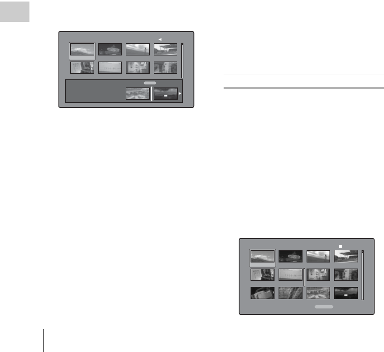
Scene Selection (Clip List Editing)
116
Chapter 5 Operations in GUI Screens
6Press the RESET/RETURN button.
This returns you to the clip thumbnail screen.
7Repeat steps 1 to 6 as required to add
more clips.
8Save the clip list (see page 118).
In step 1, you can hold down the SHIFT button
when you press the SET/S.SEL button. This is a
shortcut that displays the Add Sub Clip screen
immediately. You can also save the clip list
immediately in step 5 by executing the Save Clip
List command in the Disc Menu.
Adding sub clips from the clip list thumbnail
screen
See page 103 for more information about thumbnail
screen operations.
1Display the Thumbnail Menu.
2Select Add Sub Clips, and then press the
SET/S.SEL button or the MENU knob.
The Clip List (Add) screen appears.
3Select the sub clips that you want to add
from the upper part of the screen (the
part where 8 thumbnails are displayed,
multiple selections possible).
To select from expanded thumbnails
Press the DISP SEL/EXPAND button to
display the expand thumbnail screen.
To select from chapter thumbnails
Press the HOLD/CHAPTER button to
display the chapter thumbnail screen.
4Press the SET/S.SEL button or the
MENU knob.
The thumbnail selection is confirmed, and an
I cursor appears at the bottom of the Clip List
(Add) screen (in the Scene Selection
window). The I cursor indicates the location
where the currently selected sub clips will be
inserted.
To display the total duration after
addition of the selected clips
Press the SHIFT button.
5In the Scene Selection window, move
the I cursor to the location where you
want to insert the clip. (The existing
thumbnails arrange themselves to the
left and right of the I cursor.)
6Press the SET/S.SEL button or the
MENU knob.
The sub clips are added at the I cursor
position, and you return to the clip list
thumbnail screen.
You can check the results of the addition in
that screen.
7Repeat steps 1 to 6 as required to add
more clips.
8Save the clip list (see page 118).
In step 1, you can also perform a shortcut
operation by pressing the SET/S.SEL button with
the SHIFT button held down.
To reorder sub clips
See page 103 for more information about thumbnail
screen operations.
1In the clip list thumbnail screen, select
the thumbnails of the sub clips that you
want to move (multiple selections
possible).
2Display the Thumbnail Menu.
3Select Move Sub Clips, and then press
the SET/S.SEL button or the MENU
knob.
The Clip List (Move) screen appears.
TOTAL 00:13:48:24
Clip List (Add) 017/035002
Scene Selection
TC 00:30:25:11
TC 00:24:24:29
TC 00:30:40:13
TC 00:24:34:27
TC 01:01:28:25
TC 00:24:46:22
TC 00:09:43:14
TC 00:24:56:24
001/034
TC 00:00:00:00
TC 00:04:35:12
TC 00:06:03:03
DATE&TIME
08 AUG 2007 11:50
TOTAL DUR
00:13:48:24
TC 00:00:21:27
TC 00:04:57:10
TC 00:06:25:00
TC 00:04:06:00
TC 00:05:19:08
TC 00:06:46:27
TC 00:04:13:14
TC 00:05:41:05
TC 00:07:08:25
006Clip List (Move)

Scene Selection (Clip List Editing) 117
Chapter 5 Operations in GUI Screens
4Move the I cursor to the point where
you want to move the selected
thumbnails.
5Press the SET/S.SEL button or the
MENU knob.
The sub clips are moved to the I cursor
position.
6Repeat steps 1 to 5 as required.
7Save the clip list (see page 118).
To adjust the In and Out points of sub
clips (trim)
Proceed as follows to define the range of a scene
by changing the positions of the In and Out
points.
See page 103 for more information about thumbnail
screen operations.
1In the clip list thumbnail screen, select a
thumbnail.
2Display the Thumbnail Menu.
3Select Trim Sub Clip, and then press the
SET/S.SEL button or the MENU knob.
The Clip List (Trim) screen appears.
Like the clip playback screen, this screen
allows you to play and search all clips on the
disc.
To display a list of In and Out point
operations that you can perform
Press the MENU button.
4When you find the point that you want
to make the start point, select “IN” and
then press the SET/S.SEL button or the
MENU knob.
The timecode of the new In point appears in
the timecode display, and the Total (total
duration) and DUR (clip duration) displays
are updated.
5When you find the point that you want
to make the end point, select “OUT”
and then press the SET/S.SEL button or
the MENU knob.
The timecode of the new Out point appears in
the timecode display, and the Total (total
duration) and DUR (clip duration) displays
are updated.
To cue up the In point or Out point
Display the Thumbnail Menu, select Cue up
Inpoint or Cue up Outpoint, and then press
the SET/S.SEL button or the MENU knob.
To cancel the In point or Out point setting
Display the Thumbnail Menu, select Reset
Inpoint or Reset Outpoint, and then press the
SET/S.SEL button or the MENU knob.
The In point or Out point setting returns to
the previous value.
6Select OK, and then press the SET/
S.SEL button or the MENU knob.
7Repeat steps 1 to 6 as required.
8Save the clip list (see page 118).
To delete sub clips
See page 103 for more information about thumbnail
screen operations.
1Select the clips to delete in the clip list
thumbnail screen (multiple selections
possible).
2Display the Thumbnail Menu.
3Select Delete Sub Clips, and then press
the SET/S.SEL button or the MENU
knob.
A message appears asking you to confirm the
deletion.
4Select OK, and then press the SET/
S.SEL button or the MENU knob.
5Repeat steps 1 to 4 as required.
6Save the clip list (see page 118).
Clip List (Trim) 001/034
TCR
CLIP
01:17:33:08 019/035
01:17:33:08
Total
IN
00:13:48:24
DUR 00:00:21:27
OK
Cancel
01:17:55:05
OUT

Scene Selection (Clip List Editing)
118
Chapter 5 Operations in GUI Screens
To play the clip list
See page 103 for more information about GUI screen
operations.
To play using GUI screens
1In the clip list thumbnail screen, select
the thumbnail of the sub clip where you
want to start play.
To start play from the start of the clip list
Select the thumbnail of the first sub clip.
2Press the PLAY/PAUSE button.
To play using the clip list playback screen
1Display the clip list playback screen.
2Press the PREV button or the NEXT
button to display the sub clip that you
want to play.
To start play from the first sub clip
Press the SHIFT + PREV buttons to move to
the start of the clip list.
3Press the PLAY/PAUSE button.
To change the starting timecode of clip
lists
The timecode of clip lists is continuous timecode,
unrelated to the timecode of the original clips. By
default the timecode (LTC) of the start of the clip
list is 00:00:00:00, but it can be set to any value.
See page 103 for more information about thumbnail
screen operations.
1In the clip list thumbnail screen, display
the Thumbnail Menu.
2Select Set Start Time Code, and then
press the SET/S.SEL button or the
MENU knob.
The Set Start Time Code screen appears.
3Press the left- or right-arrow button to
select the digit that you want to change.
4Turn the MENU knob to change the
value of the digit.
5Repeat steps 3 and 4 as required.
To reset the timecode to 00:00:00:00
Select Reset to Zero in the Thumbnail Menu,
and then press the SET/S.SEL button or the
MENU knob.
To preset the frequently used timecode
Select Save Preset TC in the Thumbnail
Menu, and then press the SET/S.SEL button
or the MENU knob.
The timecode set in steps 3 and 4 is saved as
a preset value.
To recall the preset timecode
Select Recall Preset TC in the Thumbnail
Menu, and then press the SET/S.SEL button
or the MENU knob.
6Press the SET/S.SEL button or the
MENU knob.
OK is selected.
7Press the SET/S.SEL button or the
MENU knob again.
8Save the clip list (see page 118).
To save clip lists
To save under a specified name
See page 103 for more information about thumbnail
screen operations.
1In the clip list thumbnail screen, display
the Disc Menu.
2Select Save Clip List as..., and then
press the SET/S.SEL button or the
MENU knob.
TC 22 : 34 . 56 : 17
Preset TC 00:00:00:00 OK
Cancel
Set Start Time Code
H MINSEC FRM

Scene Selection (Clip List Editing) 119
Chapter 5 Operations in GUI Screens
A list of clip lists appears.
To switch the information displayed for
clip lists
Press the right-arrow button.
With each press, the display changes in the
order: “Name & Date” t “Name & Title”
t “Name & Short Date” t...
To sort clip lists
Select one of the following orders by
selecting Settings > Sort Clip List By... in the
Disc Menu.
Name(A-Z): Sort in ascending order by clip
list name.
Date(Newest First): Sort by date and time of
clip list creation, newest first.
3Select the desired clip list name, and
then press the SET/S.SEL button or the
MENU knob.
To save under the same name
The following procedure saves the current clip
list under its current name (the name that appears
in the clip list thumbnail screen).
See page 103 for more information about thumbnail
screen operations.
1In the clip list thumbnail screen, display
the Disc Menu (see page 103).
2Select Save Clip List, and then press the
SET/S.SEL button or the MENU knob.
The clip list is saved. However, Save Clip
List as... is executed when the name
displayed in the clip list thumbnail screen is
“no name”.
Note
If you press the EJECT button before saving a new or
edited clip list, a message appears asking if you want to
discard your changes and continue. Follow the
instructions in the message to continue or cancel the
operation.
To load clip lists
The following procedure loads a clip list stored on
the disc into the unit's internal memory as the
current clip list.
See page 103 for more information about thumbnail
screen operations.
1In the clip list thumbnail screen, display
the Disc Menu.
2Select Load Clip List, and then press the
SET/S.SEL button or the MENU knob.
A list of clip lists stored on the disc appears.
3Select the desired clip list, and then
press the SET/S.SEL button or the
MENU knob.
The name of the clip list selected here
appears in the clip list thumbnail screen.
When you execute the Save Clip List
command in the Disc Menu, the clip list will
be saved under that name.
To create a new clip list
Select New File and then press the SET/
S.SEL button or the MENU knob.
To clear clip lists
The following procedure clears the current clip
list from the unit’s internal memory.
See page 103 for more information about thumbnail
screen operations.
1In the clip list thumbnail screen, display
the Disc Menu.
2Select Clear Clip List, and then press
the SET/S.SEL button or the MENU
knob.
A message appears asking you to confirm
that you want to clear the clip list.
Save Clip List
E0003
E0004
E0005
E0006
E0007
E0095
E0098 Display Select
DVD og BI...
Name & Date/Sorted by Name
08 AUG2007 11:50
03 AUG2007 17:51
03 AUG2007 17:51
03 AUG2007 17:51
03 AUG2007 17:51
03 AUG2007 17:51
18 MAY2006 10:25
13 JUN2006 13:43
Disc Menu
Managing clip lists
Load Clip List
E0003
E0004
E0005
E0006
E0007
E0095
E0098 Display Select
DVD og BI...
Name & Date/Sorted by Name
08 AUG2007 11:50
03 AUG2007 17:51
03 AUG2007 17:51
03 AUG2007 17:51
03 AUG2007 17:51
03 AUG2007 17:51
18 MAY2006 10:25
13 JUN2006 13:43
Disc Menu

Scene Selection (Clip List Editing)
120
Chapter 5 Operations in GUI Screens
3Select OK, and then press the SET/
S.SEL button or the MENU knob.
The current clip list returns to the unnamed
state “(no name)”.
To delete clip lists
The following procedure deletes a clip list from
the disc.
See page 103 for more information about thumbnail
screen operations.
1In the clip list thumbnail screen, display
the Disc Menu.
2Select Delete Clip List, and then press
the SET/S.SEL button or the MENU
knob.
A list of clip lists appears.
3Select the clip list that you want to
delete, and then press the SET/S.SEL
button or the MENU knob.
A message appears asking you to confirm the
deletion.
4Select OK, and then press the SET/
S.SEL button or the MENU knob.
To sort clip lists
See page 103 for more information about thumbnail
screen operations.
1In the clip list thumbnail screen, display
the Disc Menu.
2Select Settings, and then press the SET/
S.SEL button or the MENU knob.
3Select Sort Clip List by..., and then
press the SET/S.SEL button or the
MENU knob.
4Select one of the following sort methods,
and then press the SET/S.SEL button or
the MENU knob.
Name(A-Z): Sort in ascending order by clip
list name.
Date(Newest First): Sort by date and time of
clip list creation, newest first.
Clip lists will be displayed in the specified
order the next time that you carry out an
operation such as loading a clip list.
E0001
Delete this Clip List? OK
Cancel
Delete Clip List

Disc Operations 121
Chapter 5 Operations in GUI Screens
See page 103 for more information about GUI screen
operations.
1Display the Disc Menu.
2Select Disc Properties, and then press
the SET/S.SEL button or the MENU
knob.
The Disc Properties screen appears.
User Disc ID: User disc ID 1), 2)
Title: Title 1)
Title2: Title2 1), 2)
Total DUR: Total recording time
Remain: Remaining recording time
Rewrite: Number of times rewritten
1) This can be specified with the supplied PDZ-1
Proxy Browsing Software contained on the CD-
ROM (XDCAM Application Software).
2) Titles can be displayed in European languages
when the area of use (see page 40) is set to
“NTSC AREA” or “PAL AREA”.
To scroll hidden parts of the string into
view
When a B or b mark is displayed for an item,
you can press the left or right arrow button to
scroll the display by one character for each
press.
The up and down arrow buttons scroll the
beginning and end of the string into view.
To return to the previous screen
Press the SET/S.SEL button or the MENU
knob.
To edit disc information
You can edit the user disc ID, title 1), and title 2
by using a software keyboard.
1) Only ASCII characters can be used for the title.
See “To edit clip information” (page 109) for
information about operations.
Planning metadata is a file that contains metadata
about the clips to be shot and recorded.
To use planning metadata, you will need to save a
file in advance in the specified location of a
media, and insert the media into this unit.
For details, see “To set clip names by using planning
metadata” (page 92).
To load planning metadata files
See page 103 for more information about GUI
screen operations.
1Display the Disc Menu.
2Select “Load Planning Metadata/Select
Drive”, and then press the SET/S.SEL
button or the MENU knob.
A media selection screen appears.
3Select the media where your planning
metadata file is stored, and then press
the SET/S.SEL button or the MENU
knob.
A list of the planning metadata files stored on
the media appears.
Disc Operations
Checking disc properties
User Disc ID
Title
Title2
Total DUR
Remain
Rewrite
12345
One of the memories of sum...
(none)
01:23:45:00
031min
1234times
Disc Properties OK
Horizontal Scroll
Using planning metadata
Disc Menu
Load Planning Metadata/Select Drive
Professional Disc
USB Flash Drive
Return to Upper Menu

Disc Operations
122
Chapter 5 Operations in GUI Screens
4Select the desired planning metadata
file, and then press the SET/S.SEL
button or the MENU knob.
The selected planning metadata file is loaded
into the unit’s memory, and the Planning
Metadata Properties screen appears.
5Check the information that appears,
and press the SET/S.SEL button or the
MENU knob.
To sort planning metadata
You can sort planning metadata by operating in
the same way as in “To sort clip lists” (page 120).
However, in step 3, select “Sort Planning
Metadata by...”.
The planning metadata will be displayed in the
specified order the next time you load planning
metadata.
To check planning metadata properties
You can check the properties of the planning
metadata that is loaded into this unit’s memory,
including the date and time of creation and the
clip titles.
See page 103 for more information about GUI
screen operations.
1Display the Disc Menu.
2Select “Planning Metadata Properties”,
and then press the SET/S.SEL button or
the MENU knob.
The Planning Metadata Properties screen
appears.
File Name: Planning metadata file name
Assign ID: Assign ID
Created: Date and time of creation
Modified: Date and time of most recent
modification
Modified by: Name of person who modified
the file
Title: Title 1)
Title2: Title 2
Material Gp: Material group name
1) This can be set as the clip name (see page 92).
To scroll hidden parts of the string into
view
When a B or b mark is displayed for an item,
you can press the left or right arrow button to
scroll the display by one character for each
press.
The up and down arrow buttons scroll the
beginning and end of the string into view.
To return to the previous screen
Press the SET/S.SEL button or the MENU
knob.
To clear planning metadata
See page 103 for more information about GUI
screen operations.
1Display the Disc Menu.
2Select “Clear Planning Metadata”, and
then press the SET/S.SEL button or the
MENU knob.
A message appears asking you to confirm
that you want to clear the planning metadata.
3Select “OK”, and then press the SET/
S.SEL button or the MENU knob.
The planning metadata is cleared from this
unit's memory.
Disc Menu
Load Planning Metadata/
PM_001_sample 04 AUG 10:39
04 AUG 10:39
Professional Disc
PM_002_sample
04 AUG 10:39
PM_003_sample
04 AUG 10:39
Name &Date/ Sorted by Name
PM_004_sample
File Name
Assign ID
Created
Modified
Modified by
Title
Title2
Material Gp
LatestNews0034
Projections of world economic...
21 FEB 2008 09:14 +08:00
21 FEB 2008 09:14 +08:00
Guillermo Arduino
Clip#00006
(none)
008
Planning Metadata Properties OK
Horizontal Scroll

Disc Operations 123
Chapter 5 Operations in GUI Screens
To switch the title display in the
viewfinder
When planning metadata is loaded into this unit,
you can select the format of the title to display in
the viewfinder.
See page 103 for more information about GUI
screen operations.
1Display the Disc Menu.
2Select “Settings”, and then press the
SET/S.SEL button or the MENU knob.
3Select “Planning Clip Name in Clip
Info. Area”, and then press the SET/
S.SEL button or the MENU knob.
See page 32 for more information about the
Clip Info. Area.
4Select one of the following, and then
press the SET/S.SEL button or the
MENU knob.
Off: Do not display a title.
ASCII Clip Name: Display the ASCII
format title (see page 92).
Clip Name: Display the UTF-8 format title
(see page 92).
See page 103 for more information about GUI screen
operations.
1Display the Disc Menu.
2Select Format Disc, and then press the
SET/S.SEL button or the MENU knob.
A message appears asking you to confirm the
format.
3Select OK, and then press the SET/
S.SEL button or the MENU knob.
To cancel the format
Select Cancel, and then press the SET/S.SEL
button or the MENU knob.
To continue by formatting another disc
Exchange the disc, select OK, and then press
the SET/S.SEL button or the MENU knob.
To exit the formatting screen
Press the SET/S.SEL button or the MENU
knob with Exit selected.
To disable the Format Disc command
To prevent inadvertent disc formatting, resulting
in the loss of recorded data, you can disable the
Format Disc command.
See page 103 for more information about GUI
screen operations.
1Display the Disc Menu.
2Select “Settings”, and then press the
SET/S.SEL button or the MENU knob.
3Select ‘Disable “Format Disc”’, and
then press the SET/S.SEL button or the
MENU knob.
4Select “Disable”, and then press the
SET/S.SEL button or the MENU knob.
Formatting discs
Cancel
OK
Format Disc
All Clips, Clip Lists and
Non-AV Data (General Files)
will be Deleted.
Format OK?

Shortcut List
124
Chapter 5 Operations in GUI Screens
You can access many functions from the
keyboard, without displaying a menu (shortcut
operations).
Shortcuts are available for the following
functions. The plus sign (+) indicates that one
button is held down while another is pressed, for
example “SHIFT + RESET/RETURN”.
Note
The same shortcut may access different functions,
depending on the screen that is active when it is
executed.
a) If Settings >SET Key on Thumbnail in the Disc Menu
is set to “Cue up & Play”, then play starts as soon as
cueup is ready.
b) If Settings >SET Key on Thumbnail in the Disc Menu
is set to “Cue up & Play”, then pressing the SET/
S.SEL button has the same effect.
Shortcut List
Function Operation
Clip List Thumbnail (display clip list thumbnail screen) SUB CLIP/DISC MENU
Expand Thumbnail (display expand thumbnail screen) DISP SEL/EXPAND
Chapter Thumbnail (display chapter thumbnail screen) HOLD/CHAPTER
Essence Mark Thumbnail (display essence mark thumbnail
screen)
SHIFT + THUMBNAIL/ESSENCE MARK
Add Sub Clip (add sub clip) SHIFT + SET/S.SEL
Delete Clip (delete clip) SHIFT + RESET/RETURN
Lock/Unlock Clip (lock or unlock clip) SHIFT + STOP
Set Inpoint (set In point) Left-arrow + SET/S.SEL
Set Outpoint (set Out point) Right-arrow + SET/S.SEL
Cue up Inpoint (cue up In point) Left-arrow + PREV or left-arrow + NEXT
Cue up Outpoint (cue up Out point) Right-arrow + PREV or right-arrow + NEXT
Reset Inpoint (reset In point) Left-arrow + RESET/RETURN
Reset Outpoint (reset Out point) Right-arrow + RESET/RETURN
Cue up (cue up) SET/S.SEL a)
Cue up & Play (cue up and play) PLAY/PAUSE b)
Page Down (switch to next page) SHIFT + down-arrow or F FWD
Page Up (switch to previous page) SHIFT + up-arrow or F REV
Go To End (go to the last item) SHIFT + NEXT
Go To Top (go to the first item) SHIFT + PREV
Select Multi Clip (select multiple clips) SHIFT + right-arrow or SHIFT + left-arrow
Exit (exit the current thumbnail screen) THUMBNAIL/ESSENCE MARK

Menu Organization 125
Chapter 6 Menu Displays and Detailed Settings
The following chart shows the organization of
menus in this camcorder.
[A] USER menu
[B] OPERATION menu
[C] PAINT menu
Chapter6
Menu Displays and Detailed Settings
Menu Organization
TOP MENU
USER [A]
USER MENU CUSTOMIZE
ALL
OPERATION [B]
PAINT [C]
MAINTENANCE [D]
FILE [E]
DIAGNOSIS [F]
USER OUTPUT 1
OUTPUT 2
SUPERIMPOSE
LCD
REC FUNCTION
ASSIGNABLE SW
VF DISP 1
VF DISP 2
' ! ' LED
MARKER 1
GAIN SW
VF SETTING
AUTO IRIS
SHOT ID
SHOT DISP
SET STATUS
LENS FILE
USER FILE
OPERATION OUTPUT 1
OUTPUT 2
SUPERIMPOSE
LCD
REC FUNCTION
ASSIGNABLE SW
POWER SAVE
VF DISP 1
VF DISP 2
VF DISP 3
' ! ' LED
MARKER 1
MARKER 2
GAIN SW
VF SETTING
AUTO IRIS
SHOT ID
SHOT DISP
SET STATUS
WHITE SETTING
OFFSET WHT
SHT ENABLE
LENS FILE
FORMAT
SOURCE SEL
UMID SET
CLIP TITLE
FILE NAMING
SELECT FUNCTION
PAINTSW STATUS
WHITE
BLACK/FLARE
GAMMA
BLACK GAMMA
KNEE
DETAIL 1
DETAIL 2
SD DETAIL
SKIN DETAIL
MTX LINEAR
MTX MULTI
V MODULATION
SATURATION
NOISE SUPPRESS
SCENE FILE

Menu Organization
126
Chapter 6 Menu Displays and Detailed Settings
[D] MAINTENANCE menu
[E] FILE menu
[F] DIAGNOSIS menu
The TOP menu appears when, with no menu
displayed, you hold down the MENU knob and
set the MENU ON/OFF switch to ON. The TOP
menu contains only top-level menus.
When you select a top-level menu, the most
recently shown page of that menu appears. The
CONTENTS page appears when the menu is
selected for the first time.
For details about how to use menus, see page 163.
USER menu
This menu allows you to add any desired page
from the OPERATION, PAINT,
MAINTENANCE, FILE, and DIAGNOSIS
menus to suit your needs. By gathering frequently
used pages on the USER menu beforehand, you
can call up them quickly whenever you need
them.
This menu is normally displayed when the
MENU ON/OFF switch is set to ON.
USER MENU CUSTOMIZE menu
This menu allows you to add pages to or delete
pages from the USER menu to suit your needs.
ALL menu
This menu allows you to handle all items in the
OPERATION, PAINT, MAINTENANCE, FILE,
and DIAGNOSIS menus as if they were in one
menu.
OPERATION menu
This menu contains items for changing settings
according to conditions related to the subject
when the camcorder is being operated.
PAINT menu
This menu contains items for making detailed
image adjustments while using a waveform
monitor to monitor the waveforms output by the
camera. Support of a video engineer is usually
required to use this menu. Although you can also
use an external remote control unit to set the items
on this menu, this menu is effective when using
the camcorder by itself outdoors.
TOP menu and top-level menus
MAINTENANCE WHITE SHADING
BLACK SHADING
LEVEL ADJUST
BATTERY 1
BATTERY 2
AUDIO-1
AUDIO-2
AUDIO-3
WRR SETTING
TIMECODE
ESSENCE MARK
CAM CONFIG 1
CAM CONFIG 2
PRESET WHITE
WHITE FILTER
DCC ADJUST
AUTO IRIS 2
GENLOCK
ND COMP
AUTO SHADING
APR
NETWORK
UP CONVERTER
FILE USER FILE
USER FILE 2
ALL FILE
SCENE FILE
REFERENCE
LENS FILE 1
LENS FILE 2
LENS FILE 3
MEMORY STICK
DIAGNOSIS HOURS METER
TIME/DATE
ROM VERSION 1
ROM VERSION 2
ROM VERSION 3
DEV STATUS
OPTION
<TOP MENU>
USER
USER MENU CUSTOMIZE
ALL
OPERATION
PAINT
MAINTENANCE
FILE
DIAGNOSIS

Menu Organization 127
Chapter 6 Menu Displays and Detailed Settings
MAINTENANCE menu
This menu contains items for making settings for
audio, timecode, essence marks, and battery.
FILE menu
This menu is for saving the adjusted data in the
camcorder memory or in a “Memory Stick”. The
following files can be saved.
User files
User files save the setting items and setting data
of customized USER menus. You can save up to
100 user files in a “Memory Stick”. Once you
save a user file in a “Memory Stick”, you can
easily set the USER menu to your preference by
loading the file.
For details on user files, see “Saving and Recalling
User Files” on page 186.
ALL files
ALL files save the setting data of all of the menus.
You can save up to 100 ALL files in a “Memory
Stick”.
Once a camcorder is set up according to your
preferences and you save an ALL file in a
“Memory Stick”, you can easily set other
camcorders to those settings by loading the data
from the “Memory Stick”.
Note
Device specific data (output levels and shading that
requires adjustment for the specific device) is not saved.
Scene files
In the scene file, the setting values of PAINT
menu items set to shoot a particular scene are
saved. You can save up to five scene files in the
camcorder memory and up to 100 scene files in a
“Memory Stick”. For example, first adjust the
settings to shoot a rehearsal of a particular scene
and then save them as a scene file. Then load that
file before the actual shooting so that you can
quickly recreate setup conditions of the rehearsal.
Reference files
Reference files save the reference values that are
set when STANDARD is executed in the SCENE
FILE page of the PAINT menu. You can save one
reference file in the internal memory of the unit
and one in a “Memory Stick”.
Lens files
Lens files save the setting data used to
compensate for the characteristics of lenses, such
as flare, white shading, and auto iris gain. You
can save up to 32 lens files in the internal memory
of the unit and up to 100 lens files in a “Memory
Stick”.
DIAGNOSIS menu
This menu shows the digital hours meter, the
ROM version, and information about the internal
device status of the camcorder.

Menu List
128
Chapter 6 Menu Displays and Detailed Settings
Tips
• The bold-faced numbers designate the pages that have been registered in the USER menu at the factory.
• The following lists include items and settings that appear only when an option board or separately sold
software is installed.
• The bold-faced settings are the factory default settings.
• The initial value of items with a setting range of –99 to 99 is 0.
• When the setup value in the Settings column is surrounded by parentheses ( ), the value is a relative
value. The setting range shown on the menu screen may differ from what is shown in the manual.
Menu List
OPERATION menu
No. Page Item Settings Description
01 OUTPUT 1 SDI OUT 1 SELECT OFF/HDSDI/SDSDI Selects the output signal from the
SDI OUT 1 connector.
SDI OUT 2 SELECT OFF/HDSDI/SDSDI Selects the output signal from the
SDI OUT 2 connector.
SDI OUT 2 SUPER OFF/ON Sets the superimposed
information output from the SDI
OUT 2 connector.
TEST OUT SELECT VBS/Y/R/G/B/LCD Selects the output signal from the
TEST OUT connector.
Note
When R, G, or B is selected, turning
the power of the unit off and on
changes the setting to Y.
TEST OUT SUPER OFF/ON Sets the superimposed
information output from the
TEST OUT connector.
Notes
• Regardless of this setting, text
data is output from this connector
when the setting of TEST OUT
SELECT is Y, R, G, or B. During
the display of text data, you can
hide the text data by switching
this item from ON to OFF. (It is
also hidden in the viewfinder.)
• When TEST OUT SELECT is set
to LCD, the mode selected with
the DISP SEL/EXPAND button
determines whether text is
displayed or hidden.

Menu List 129
Chapter 6 Menu Displays and Detailed Settings
02 OUTPUT 2 LIVE & PLAY OFF/ON For details, see “To display
camera video in the viewfinder
during playback (Live & Play
function)” on page 78.
DOWN CON MODE CROP/LETTR/SQEZE
(LETTR is displayed
when the LETTER BOX
item on the SELECT
FUNCTION page is set
to “ENABL”.)
Sets the conversion mode for
down-converted output.
WIDE ID THROU/AUTO Specifies whether to add wide
picture information to the SD
output signal.
THROU: Output the video
signals without adding wide
picture information.
AUTO: When the DOWN CON
MODE item is set to
SQEZE, add wide picture
information to the output
video signals.
03 SUPER IMPOSE SUPER(VFDISP) OFF/ON When the SDI OUT 2 SUPER
item or the TEST OUT SUPER
item on the OUTPUT 1 page is
set to ON, turn the output of text
(superimposed) information from
the SDI OUT 2 or TEST OUT
connector on or off for each item.
SUPER(MENU) OFF/ON
SUPER(TC) OFF/ON
SUPER(MARKER) OFF/ON When the TEST OUT SUPER
item on the OUTPUT 1 page is
set to ON, turns the marker
display output from the TEST
OUT connector on or off.
04 LCD LCD COLOR (–99 to 99) Adjusts the LCD color.
LCD
MARKER&ZEBRA
OFF/ON Turns the marker and zebra
display in the LCD monitor on or
off.
No. Page Item Settings Description

Menu List
130
Chapter 6 Menu Displays and Detailed Settings
05 REC FUNCTION CACHE/INTVAL REC OFF/CACHE/A. INT/
M. INT
For details, see “Starting a shoot
with a few seconds of pre-stored
picture data (Picture Cache
function)” on page 81 and “Time-
lapse video (Interval Rec
function)” on page 82.
CACHE REC TIME 0-2S/2-4S/4-6S/6-8S/8-
10S/18-20S/28-30S
TAKE TOTAL TIME 5MIN/10MIN/15MIN/
20MIN/30MIN/40MIN/
50MIN/1H/2H/3H/4H/
5H/7H/10H/15H/20H/
30H/40H/50H/70H/
100H
REC TIME 5SEC/10SEC/15SEC/
20SEC/30SEC/40SEC/
50SEC/1MIN to 85MIN
PRE-LIGHTING OFF/2SEC/5SEC/
10SEC
NUMBER OF FRAME When SYSTEM LINE is
set to 720 and REC
FORMAT is set to
HD422 50, HD420
HQ, or HD420 SP:
2/6/12
When either SYSTEM
LINE or REC
FORMAT is set to
another setting: 1/3/
6
TRIGGER INTERVAL M/1SEC to 10SEC/
15SEC/20SEC/30SEC/
40SEC/50SEC/1MIN to
10MIN/15MIN/20MIN/
30MIN/40MIN/50MIN/
1H/2H/3H/4H/6H/12H/
24H
DISC EXCHG CACHE OFF/ON
06 ASSIGNABLE
SW
ASSIGN SW <1> For details, see “Assigning
functions to ASSIGN switches” on
page 178.
ASSIGN SW <2>
ASSIGN SW <3>
ASSIGN SW <4>
ASSIGN SW <RET>
COLOR TEMP SW
ZOOM SPEED 0 to 20 to 99
RETURN VIDEO OFF/ON
07 POWER SAVE ETHERNET/USB DSABL/ENABL For details, see “Setting power
saving functions” on page 181.
i.LINK(FAM) DSABL/ENABL
REC AUDIO OUT EE/SAVE
TEST OUT SAVE OFF/ON
No. Page Item Settings Description

Menu List 131
Chapter 6 Menu Displays and Detailed Settings
08 VF DISP 1 VF DISP OFF/ON For details, see “Selecting the
display items” on page 171.
VF DISP MODE 1/2/3
DISP EXTENDER OFF/ON
DISP FILTER OFF/ON
DISP WHITE OFF/ON
DISP GAIN OFF/ON
DISP SHUTTER OFF/ON
DISP AUDIO OFF/ON
DISP DISC OFF/ON
DISP IRIS OFF/ON
09 VF DISP 2 DISP ZOOM OFF/ON
DISP COLOR TEMP OFF/ON
DISP BATT REMAIN INT/VOLT/AUTO
DISP DC IN OFF/ON
DISP 16:9/4:3 ID
(When the CBKZ-
MD01 is installed)
OFF/ON
DISP WRR RF LVL OFF/ON
DISP REC FORMAT OFF/ON
DISP CLIP NO(PB) OFF/ON
DISP TIMECODE OFF/ON
10 VF DISP 3 LOW LIGHT OFF/ON
LOW LIGHT LEVEL (–99 to 99)
VF BATT WARNING 10%/20%
ABSOLUTE VALUE OFF/ON
11 ‘!’ LED GAIN <!> OFF/ON For details, see “Indicators” on
page 31.
SHUTTER <!> OFF/ON
WHT PRESET <!> OFF/ON
ATW RUN <!> OFF/ON
EXTENDER <!> OFF/ON
FILTER <!> OFF/ON
OVERRIDE <!> OFF/ON
No. Page Item Settings Description

Menu List
132
Chapter 6 Menu Displays and Detailed Settings
12 MARKER 1 MARKER OFF/ON For details, see “Setting the
marker display” on page 173.
CENTER OFF/ON
CENTER MARK 1/2/3/4
SAFTY ZONE OFF/ON
SAFTY AREA 80%/90%/92.5%/95%
ASPECT OFF/ON
ASPECT SELECT 15:9/14:9/13:9/4:3/1.85/
2.35
ASPECT MASK OFF/ON
ASPECT MASK LVL 0 to 12 to 15
100% MARKER OFF/ON
13 MARKER 2 USER BOX OFF/ON
USER BOX WIDTH 3 to 240 to 479
USER BOX HEIGHT 3 to 135 to 269
USER BOX H POS –477 to 0 to 476
USER BOX V POS –267 to 0 to 266
CENTER H POS –480 to 0 to 479
CENTER V POS –270 to 0 to 269
ASPECT SAFE ZONE OFF/ON
ASPECT SAFE AREA 80%/90%/92.5%/95%
14 GAIN SW GAIN LOW –6dB/–3dB/0dB/3dB/
6dB/9dB/12dB/18dB/
24dB/30dB/36dB/42dB
For details, see “Setting gain
values for the GAIN selector
positions” on page 177.
GAIN MID –6dB/–3dB/0dB/3dB/
6dB/9dB/12dB/18dB/
24dB/30dB/36dB/42dB
GAIN HIGH –6dB/–3dB/0dB/3dB/
6dB/9dB/12dB/18dB/
24dB/30dB/36dB/42dB
GAIN TURBO –6dB/–3dB/0dB/3dB/
6dB/9dB/12dB/18dB/
24dB/30dB/36dB/42dB
TURBO SW IND OFF/ON
SHOCKLESS GAIN
(Does not appear when
the SCAN MODE item
on the FORMAT page
is set to 23.9P.)
OFF/ON
No. Page Item Settings Description

Menu List 133
Chapter 6 Menu Displays and Detailed Settings
15 VF SETTING ZEBRA OFF/ON For details, see “Setting the
viewfinder” on page 174.
ZEBRA SELECT 1/2/BOTH
ZEBRA1 DET LVL 20% to 70% to 107%
ZEBRA1 APT LVL 1% to 10% to 20%
ZEBRA2 DET LVL 52% to 100% to 109%
VF DETAIL LEVEL (–99 to 99)
VF ASPECT (SD)
(When the REC
FORMAT item is set to
IMX50, IMX40,
IMX30, or DVCAM)
AUTO/16:9
16 AUTO IRIS IRIS OVERRIDE OFF/ON For details, see “Changing the
Reference Value for Automatic
Iris Adjustment” on page 63.
IRIS SPEED (–99 to 99)
CLIP HIGH LIGHT OFF/ON
IRIS WINDOW 1/2/3/4/5/6/VAR
IRIS WINDOW IND OFF/ON
IRIS VAR WIDTH 20 to 240 to 479
IRIS VAR HEIGHT 20 to 135 to 269
IRIS VAR H POS –460 to 0 to 459
IRIS VAR V POS –250 to 0 to 249
17 SHOT ID ID-1 Blank/up to 12
characters
For details, see “Setting the shot
ID” on page 175.
ID-2 Blank/up to 12
characters
ID-3 Blank/up to 12
characters
ID-4 Blank/up to 12
characters
18 SHOT DISP SHOT DATE OFF/ON For details, see “Recording shot
data superimposed on the color
bars” on page 174.
SHOT TIME OFF/ON
SHOT MODEL NAME OFF/ON
SHOT SERIAL NO OFF/ON
SHOT ID SEL OFF/ID-1/ID-2/ID-3/
ID-4
SHOT 16:9 CHARA OFF/ON
SHOT BLINK CHARA OFF/ON
19 SET STATUS STATUS ABNORMAL OFF/ON For details, see “Displaying the
status confirmation screens” on
page 176.
STATUS SYSTEM OFF/ON
STATUS FUNCTION OFF/ON
STATUS AUDIO OFF/ON
No. Page Item Settings Description

Menu List
134
Chapter 6 Menu Displays and Detailed Settings
20 WHITE
SETTING
WHITE SWITCH <B> MEM/ATW Specifies the operating mode
when the WHITE BAL switch is
set to the B side.
MEM: Auto white balance
ATW: Auto tracing white balance
SHOCKLESS WHITE OFF/1/2/3 Specifies the transition time when
the WHITE BAL switch is
changed to a new setting (1 is
fastest)
ATW SPEED 1/2/3/4/5 Switches the transition speed of
auto tracing white balance (ATW)
(1 is fastest)
AWB FIXED AREA OFF/ON Executes AWB (auto white
balance) at the center of the
screen.
FILTER WHT MEM OFF/ON Specifies whether to allocate a
white balance memory slot for
each position number of the
FILTER selector.
21 OFFSET WHT OFFSET WHITE <A> OFF/ON For details, see “Specifying an
offset for the auto white balance
setting” on page 182.
WARM-COOL <A> Displays reference color
temperature
WARM-COOL BAL
<A>
(–99 to 99)
OFFSET WHITE <B> OFF/ON
WARM-COOL <B> Displays reference color
temperature
WARM-COOL BAL
<B>
(–99 to 99)
22 SHT ENABLE SHUTTER ECS OFF/ON The items which can be set differ
depending on the setting of the
SYSTEM FREQUENCY item on
the FORMAT page. For details,
see “Setting the Electronic
Shutter” on page 60.
When SCAN MODE is set to
23.9P, more shutter speeds can be
selected and the SHT ENABLE 2
page appears to display them.
SHUTTER SLS OFF/ON
SHUTTER 1/32 OFF/ON
SHUTTER 1/33 OFF/ON
SHUTTER 1/40 OFF/ON
SHUTTER 1/48 OFF/ON
SHUTTER 1/50 OFF/ON
SHUTTER 1/60 OFF/ON
SHUTTER 1/96 OFF/ON
SHUTTER 1/100 OFF/ON
SHUTTER 1/120 OFF/ON
SHUTTER 1/125 OFF/ON
SHUTTER 1/250 OFF/ON
SHUTTER 1/500 OFF/ON
SHUTTER 1/1000 OFF/ON
SHUTTER 1/2000 OFF/ON
No. Page Item Settings Description

Menu List 135
Chapter 6 Menu Displays and Detailed Settings
23 LENS FILE LENS FILE SELECT 1 to 32 For details, see “Selecting the
lens file” on page 182.
F.ID Display only
L.ID Display only
L.MF Display only
24 FORMAT SYSTEM LINE 1080/720 The selectable SYSTEM
FREQUENCY settings differ
depending on the setting of
SYSTEM LINE. For details, see
“Setting the Recording Format”
(page 54).
SYSTEM
FREQUENCY
59.9i/29.9P/50i/25P/
59.9P/50P
SCAN MODE
(Only when SYSTEM
LINE is set to 720, and
SYSTEM
FREQUENCY is set to
59.9P.)
59.9P/23.9P
REC FORMAT HD422 50/HD420 HQ/
HD420 SP/IMX50/
IMX40/IMX30/
DVCAM
(IMX50, IMX40,
IMX30, and DVCAM
are displayed when the
CBKZ-MD01 is
installed.)
ASPECT RATIO (SD)
(When the REC
FORMAT item is set to
IMX50, IMX40,
IMX30, or DVCAM)
16:9/4:3 The selectable settings differ
depending on the setting of REC
FORMAT. For details, see
“Setting the Recording Format”
(page 54).
AU DATA LEN (IMX)
(When the REC
FORMAT item is set to
IMX50, IMX40, or
IMX30)
16bit/24bit
COUNTRY NTSC(J)AREA/NTSC
AREA/PAL AREA
For details, see “Setting the Area
of Use” on page 40.
No. Page Item Settings Description

Menu List
136
Chapter 6 Menu Displays and Detailed Settings
25 SOURCE SEL FRONT MIC SELECT
(When stereo
microphone is
connected)
MONO/STREO Input mode selection for front
microphone.
REC VIDEO SOURCE
(When the CBK-HD01
or CBK-SC02 option
board is installed)
CAM/EXT For details, see “Recording video
from external devices” (page 93).
EXT VIDEO SOURCE
(When the CBK-HD01
or CBK-SC02 option
board is installed)
VBS/SDSDI/HDSDI
(VBS is displayed when
the CBK-SC02 is
installed. SDSDI and
HDSDI are displayed
when the CBK-HD01 is
installed.)
WIDE MODE(EXT)
(When the CBK-HD01
or CBK-SC02 option
board is installed)
AUTO/16:9 When the input signal is SD,
select the method that determines
whether the signal is treated as a
wide signal.
AUTO: When wide picture
information is detected in the
input signal, treat the signal
as a wide signal and set the
up-converter operating mode
to squeeze mode. Record
wide picture information
when recording SD. When
wide picture information is
not detected, set the up-
converter operating mode to
edge crop mode and do not
record wide picture
information.
16:9: Always treat the signal as a
wide signal and set the up-
converter operating mode to
squeeze mode. Record wide
picture information when
recording SD.
SETUP REMOVE
(When the COUNTRY
item is set to
“NTSC(J)AREA” or
“NTSC AREA” and the
CBK-SC02 option
board is installed)
0.0%/7.5% Selects whether to modify the
setup level of input video signals.
7.5%: Remove the setup. (Select
when signals with 7.5%
setup are input.)
0.0%: Do not remove the setup.
(Select when signals without
setup are input.)
26 UMID SET COUNTRY CODE Blank/up to 4 characters For details, see “Setting the
UMID data” on page 183.
ORGANIZATION Blank/up to 4 characters
USER CODE Blank/up to 4 characters
TIME ZONE 00 to 3F
No. Page Item Settings Description

Menu List 137
Chapter 6 Menu Displays and Detailed Settings
27 CLIP TITLE TITLE DSABL/ENABL For details, see “Assigning user-
defined clip titles automatically”
on page 87.
SELECT PREFIX
(When the TITLE item
is set to “ENABL”)
EXEC
CLEAR NUMERIC
(When the TITLE item
is set to “ENABL”)
EXEC
LOAD PREFIX DATA
(When the TITLE item
is set to “ENABL”)
EXEC
PREFIX
(When the TITLE item
is set to “ENABL”)
TITLE/up to 10
characters
NUMERIC
(When the TITLE item
is set to “ENABL”)
00001 to 99999
28 FILE NAMING NAMING FORM C****/FREE For details, see “Assigning user-
defined names to clips and clip
lists” on page 90.
AUTO NAMING
(When the NAMING
FORM item is set to
“FREE”)
C****/TITLE/PLAN
No. Page Item Settings Description

Menu List
138
Chapter 6 Menu Displays and Detailed Settings
29 SELECT
FUNCTION
LETTER BOX DISABLE/ENABLE Enable the selection of “LETTR”
(LETTER BOX) in the DOWN
CON MODE item on the
OUTPUT 2 page.
Note
Breakup may occur in output
signals and in the video and audio
of this unit for about 5 to 10
seconds immediately after this
setting is changed.
FOCUS MAG DISABLE/ENABLE Enable the assignment of the
FOCUS MAG function to the
ASSIGN switches.
Note
Breakup may occur in output
signals and in the video and audio
of this unit for about 5 to 10
seconds immediately after this
setting is changed.
HD t SD PHASE
DELAYED
Display only Appears when LETTER BOX is
set to “ENABLE”, or when
FOCUS MAG is set to
“ENABLE”.
Note
In these states, the phases of HD
output and SD output from this unit
do not match.
REF t HD-Y PHASE
DELAYED
Display only Appears when FOCUS MAG is
set to “ENABLE”.
Note
In this state, the phase of HD-Y
output from this unit does not match
the phase of the GENLOCK IN
signal. When multiple PDW-700
units are daisy chained via this unit
(see page 70), inter-system phases
do not match.
No. Page Item Settings Description

Menu List 139
Chapter 6 Menu Displays and Detailed Settings
PAINT menu
No. Page Item Settings Description
01 SW STATUS GAMMA OFF/ON Turns the gamma correction on
or off.
BLACK GAMMA OFF/ON Turns the black gamma
correction on or off.
MATRIX OFF/ON Turns the linear matrix correction
and user-set matrix correction
functions on or off.
KNEE OFF/ON Turns the knee correction on or
off.
WHITE CLIP OFF/ON Turns the white clipping
correction on or off.
DETAIL OFF/ON Turns the detail signal on or off.
APERTURE OFF/ON Turns the aperture function on or
off.
FLARE OFF/ON Turns the flare function on or off.
TEST SAW OFF/ON Selects the test signal.
02 WHITE COLOR TEMP <A> Displays reference color
temperature.
Sets the color temperature of
WHITE A.
C TEMP BAL <A> (–99 to 99) Adjusts the value more precisely
when the color temperature
adjustment through COLOR
TEMP is not satisfactory.
R GAIN <A> (–99 to 99) Only the value of R GAIN is
changed.
B GAIN <A> (–99 to 99) Only the value of B GAIN is
changed.
COLOR TEMP <B> Displays reference color
temperature.
Sets the color temperature of
WHITE B.
C TEMP BAL <B> (–99 to 99) Adjusts the value more precisely
when the color temperature
adjustment through COLOR
TEMP is not satisfactory.
R GAIN <B> (–99 to 99) Only the value of R GAIN is
changed.
B GAIN <B> (–99 to 99) Only the value of B GAIN is
changed.

Menu List
140
Chapter 6 Menu Displays and Detailed Settings
03 BLACK/FLARE MASTER BLACK (–99 to 99) Adjusts the master black level.
R BLACK (–99 to 99) Adjusts the R black level.
B BLACK (–99 to 99) Adjusts the B black level.
MASTER FLARE (–99 to 99) Adjusts the flare level of the
master.
R FLARE (–99 to 99) Adjusts the R flare level.
G FLARE (–99 to 99) Adjusts the G flare level.
B FLARE (–99 to 99) Adjusts the B flare level.
FLARE OFF/ON Turns the flare correction circuit
on or off.
TEST OUT SELECT VBS/Y/R/G/B/LCD Selects the output signal of TEST
OUT connector.
04 GAMMA GAMMA OFF/ON Turns the gamma correction
function on or off.
STEP GAMMA 0.35 to 0.45 to 0.90 Sets the gamma correction curve
by steps.
MASTER GAMMA (–99 to 99) Sets the master gamma
correction curve.
R GAMMA (–99 to 99) Sets the R gamma correction
curve.
G GAMMA (–99 to 99) Sets the G gamma correction
curve.
B GAMMA (–99 to 99) Sets the B gamma correction
curve.
TEST OUT SELECT VBS/Y/R/G/B/LCD Selects the output signal of TEST
OUT connector.
GAMMA TABLE STD/HG Selects the gamma type.
STD: Standard gamma
HG: Hyper gamma
GAM TABLE(STD) 1 to 5 to 6 Selects the standard gamma type.
1: Corresponds to SD camcorder
2: x 4.5 gain
3: x 3.5 gain
4: Corresponds to SMPTE-240M
5: Corresponds to ITU-R709
6: x 5.0 gain
GAM TABLE(HG) 1 to 4Selects the hyper gamma type.
1: 325% to 100%
2: 460% to 100%
3: 325% to 109%
4: 460% to 109%
No. Page Item Settings Description

Menu List 141
Chapter 6 Menu Displays and Detailed Settings
05 BLACK
GAMMA
BLACK GAMMA OFF/ON Turns the black gamma
correction on or off.
BLACK GAM RANGE LOW/L.MID/H.MID/
HIGH
Sets the range affected by black
gamma.
MASTER BLK
GAMMA
(–99 to 99) Adjusts the master black gamma.
R BLACK GAMMA (–99 to 99) Sets the correction curve of the R
black gamma.
G BLACK GAMMA (–99 to 99) Sets the correction curve of the G
black gamma.
B BLACK GAMMA (–99 to 99) Sets the correction curve of the B
black gamma.
TEST OUT SELECT VBS/Y/R/G/B/LCD Selects the output signal of TEST
OUT connector.
06 KNEE KNEE OFF/ON Turns the knee correction circuit
on or off.
KNEE POINT 50.0% to 95.0% to
109.0%
Sets the knee point level.
KNEE SLOPE (–99 to 99) Set the knee slope level.
KNEE SATURATION OFF/ON Turns the knee saturation
function on or off.
KNEE SAT LEVEL (–99 to 99) Sets the knee saturation level.
WHITE CLIP OFF/ON Turns the white clipping function
on or off.
WHITE CLIP LEVEL NTSC: 90.0% to
108.0% to 109.0%
PAL: 90.0% to 105.0%
to 109.0%
Adjusts the white clipping level.
07 DETAIL 1 DETAIL OFF/ON Sets the detail correction function
on or off.
APERTURE OFF/ON Turns the aperture correction
function on or off.
DETAIL LEVEL (–99 to 99) Sets the general level of the detail
signal.
APERTURE LEVEL (–99 to 99) Sets the aperture correction level.
DTL H/V RATIO (–99 to 99) Sets the level of the V detail
signal.
CRISPENING (–99 to 99) Sets the crispening level.
LEVEL DEPEND OFF/ON Turns the level depend function
on or off.
LEVEL DEPEND LVL (–99 to 99) Sets the level of the level depend.
DETAIL FREQUENCY (–99 to 99) Sets the frequency of the H detail
signal.
No. Page Item Settings Description

Menu List
142
Chapter 6 Menu Displays and Detailed Settings
08 DETAIL 2 KNEE APERTURE OFF/ON Turns the knee aperture function
on or off.
KNEE APT LVL (–99 to 99) Sets the knee aperture level.
DETAIL LIMIT (–99 to 99) Sets the both detail black and
white limiters.
DTL WHT LMT (–99 to 99) Sets the detail white limiter.
DTL BLK LMT (–99 to 99) Sets the detail black limiter.
DTL V-BLK LMT (–99 to 99) Sets the V detail black limiter.
V DTL CREATION NAM/G/R+G/Y Selects the source signal of the V
DTL signal.
H/V CONTROL MODE H/V/VSelects the operation mode of
DTL H/V RATIO on the
DETAIL 1 page.
H/V: H and V increase and
decrease in inverse
proportion
V: V DTL only enabled
09 SD DETAIL SD DETAIL OFF/ON Turns the SD detail correction on
or off.
SD DETAIL LEVEL (–99 to 99) Sets the general level of the SD
detail signal.
SD CRISPENING (–99 to 99) Sets the SD crispening level.
SD DTL WHT LIMIT (–99 to 99) Sets the SD detail white limiter.
SD DTL BLK LIMIT (–99 to 99) Sets the SD detail black limiter.
SD LEVEL DEPEND OFF/ON Turns the SD level depend
function on or off.
SD LV DEPEND LVL (–99 to 99) Sets the level of the SD level
depend.
SD DTL FREQUENCY (–99 to 99) Sets the frequency of the SD H
detail signal.
SD DTL H/V RATIO (–99 to 99) Sets the level of the SD V detail
signal.
SD CROSS COLOR
(When NTSC(J)AREA
or NTSC AREA is
selected on the
FORMAT page)
(–99 to 99) Sets the SD cross color reduction
level.
No. Page Item Settings Description

Menu List 143
Chapter 6 Menu Displays and Detailed Settings
10 SKIN DETAIL SKIN DETAIL ALL OFF/ON Turns on or off all of channels 1,
2 and 3 for the color detail
function.
SKIN DETECT Moves to color detection
page.
Executes the color detail
function.
SKIN AREA IND OFF/ON Turns on and off the function that
displays a zebra pattern where
color was detected.
SKIN DTL SELECT 1/2/3 Selects the type of the color
detail function. The following
items depend on the selected type
of the color detail function.
SKIN DETAIL OFF/ON Turns the color detail function on
or off for the type selected in the
above item.
SKIN DETAIL LVL (–99 to 99) Sets the level of the color detail
signal.
SKIN DTL SAT (–99 to 99) Adjusts the saturation level of the
hue possessed by the color detail
function.
SKIN DTL HUE 0 to 359 Adjusts the center phase of the
hue possessed by the color detail
function.
SKIN DTL WIDTH 0 to 39 to 359 Adjusts the width of the hue
possessed by the color detail
function.
11 MTX LINEAR MATRIX OFF/ON Turns the linear matrix correction
and user-set matrix correction
functions on or off.
MATRIX(USER) OFF/ON Turns the user-set matrix
correction function on or off.
MATRIX(PRESET) OFF/ON Turns the preset matrix
correction function on or off.
MATRIX(PRST) SEL 1/2/3/4/5/6 Selects the preset matrix
correction function.
MATRIX(USER) R-G (–99 to 99) Sets the arbitrary R-G user-set
matrix coefficients.
MATRIX(USER) R-B (–99 to 99) Sets the arbitrary R-B user-set
matrix coefficients.
MATRIX(USER) G-R (–99 to 99) Sets the arbitrary G-R user-set
matrix coefficients.
MATRIX(USER) G-B (–99 to 99) Sets the arbitrary G-B user-set
matrix coefficients.
MATRIX(USER) B-R (–99 to 99) Sets the arbitrary B-R user-set
matrix coefficients.
MATRIX(USER) B-G (–99 to 99) Sets the arbitrary B-G user-set
matrix coefficients.
No. Page Item Settings Description

Menu List
144
Chapter 6 Menu Displays and Detailed Settings
12 MTX MULTI MATRIX OFF/ON Turns the linear matrix correction
and multi matrix correction
functions on or off.
MATRIX (MULTI) OFF/ON Turns the multi matrix correction
function on or off.
MATRIX AREA IND OFF/ON Turns the zebra indication on or
off in the area corresponding to
the currently selected setting.
MATRIX COLOR DET Moves to color detection
page.
Detects color.
MTX(MULTI)PRESET EXEC Return MTX(MULTI)HUE and
MTX(MULTI)SAT values to
preset values for each of the 16
axes.
MTX (MULTI) AXIS B/B+/MG–/MG/MG+/
R/R+/YL–/YL/YL+/G–/
G/G+/CY/CY+/B–
Sets 16 hue axes as the targets of
the multi matrix correction
function.
MTX (MULTI) HUE (–99 to 99) Sets hue correction values for
each of the 16 axis modes.
MTX (MULTI) SAT (–99 to 99) Sets saturation correction values
for each of the 16 axis modes.
13 V
MODULATION
V MOD OFF/ON Turns the V modulation function
on or off.
MASTER VMOD (–99 to 99) Adjusts the master V modulation
level.
R VMOD (–99 to 99) Adjusts the R V modulation
level.
G VMOD (–99 to 99) Adjusts the G V modulation
level.
B VMOD (–99 to 99) Adjusts the B V modulation
level.
TEST OUT SELECT VBS/Y/R/G/B/LCD Selects the output signal of the
TEST OUT connector.
14 SATURATION LOW KEY SAT OFF/ON Turns the low key saturation
function on or off.
L KEY SAT LEVEL (–99 to 99) Sets the saturation level of the
low luminance part.
L KEY SAT RANGE LOW/L.MID/H.MID/
HIGH
Sets the luminance level at which
the low key saturation function
becomes effective.
Y BLACK GAMMA OFF/ON Turns the Y black gamma
function on or off.
Y BLK GAM LEVEL (–99 to 99) Sets the gamma curve in the low
luminance part.
Y BLK GAM RANGE LOW/L.MID/H.MID/
HIGH
Sets the luminance level at which
the Y black gamma becomes
effective.
15 NOISE
SUPPRESS
NOISE SUPPRESS OFF/ON Turn on and off the noise
suppression function.
No. Page Item Settings Description

Menu List 145
Chapter 6 Menu Displays and Detailed Settings
16 SCENE FILE 1 STANDARD Recalls the scene file saved in the
memory of the camcorder.
2 STANDARD
3 STANDARD
4 STANDARD
5 STANDARD
STANDARD – Clears all current detail-adjusted
settings and switch settings and
returns the settings to the
standard settings saved in the
reference file.
SCENE RECALL – Recalls the scene file from the
memory of the camcorder or the
“Memory Stick”.
SCENE STORE – Stores the scene file in the
memory of the camcorder or the
“Memory Stick”.
F.ID Blank/up to 16
characters
Sets the File ID.
MAINTENANCE menu
No. Page Item Settings Description
01 WHITE
SHADING
WHT SHAD CH
SEL
R/G/B/TEST Selects the channel adjusted by this menu. If TEST
is selected, the setting is linked to the setting of
TEST OUT SELECT.
TEST OUT
SELECT
VBS/Y/R/G/B/
LCD
Selects the signal output of the TEST OUT
connector.
R/G/B WHT H
SAW
(–99 to 99) H Saw white shading compensation.
R/G/B WHT H
PARA
(–99 to 99) H Parabola white shading compensation.
R/G/B WHT V
SAW
(–99 to 99) V Saw white shading compensation.
R/G/B WHT V
PARA
(–99 to 99) V Parabola white shading compensation.
WHITE SAW/
PARA
OFF/ON Turns white shading Saw and Parabola
compensation on and off.
No. Page Item Settings Description

Menu List
146
Chapter 6 Menu Displays and Detailed Settings
02 BLACK
SHADING
BLK SHAD CH
SEL
R/G/B/TEST/
LCD
Selects the channel adjusted by this menu. If
“TEST” is selected, the setting is the same as the
setting of TEST OUT SELECT.
TEST OUT
SELECT
VBS/Y/R/G/B/
LCD
Selects the signal output of the TEST OUT
connector.
R/G/B BLK H
SAW
(–99 to 99) H Saw black shading compensation.
R/G/B BLK H
PARA
(–99 to 99) H Parabola black shading compensation.
R/G/B BLK V
SAW
(–99 to 99) V Saw black shading compensation.
R/G/B BLK V
PARA
(–99 to 99) V Parabola black shading compensation.
BLACK SAW/
PARA
OFF/ON Turns black shading Saw and Parabola
compensation on and off.
MASTER BLACK (–99 to 99) Master black level adjustment.
MASTER
GAIN(TMP)
–6dB/–3dB/0dB/
3dB/6dB/9dB/
12dB/18dB/
24dB/30dB/
36dB/42dB
Temporarily adjusts the master gain value.
03 LEVEL
ADJUST
VBS VIDEO
LEVEL
(–99 to 99) Adjusts the composite signal video level.
HD-Y LEVEL (–99 to 99) Adjusts the Y level of the HD component signal.
TEST OUT
SELECT
VBS/Y/R/G/B/
LCD
Selects the signal output of the TEST OUT
connector.
No. Page Item Settings Description

Menu List 147
Chapter 6 Menu Displays and Detailed Settings
04 BATTERY 1 Info BEFORE
END
5%/10%/
15%...95%/
100%
Used when a BP-GL65/GL95 Battery Pack is used.
Sets the remaining power (% value) of the battery
at which the BEFORE END warning should be
issued. a)
Info END 0%/1%/2%/3%/
4%/5%
Used when a BP-GL65/GL95 Battery Pack is used.
Sets the remaining power (% value) of the battery
at which the END warning should be issued. b)
Sony BEFORE
END
11.5V to 17.0V
(in 0.1V steps)
Used when a BP-L60S/L80S Battery Pack is used.
Sets the voltage level of the battery at which the
BEFORE END warning should be issued. a)
Sony END 11.0V to 11.5V
(in 0.1V steps)
Used when a BP-L60S/L80S Battery Pack is used.
Sets the voltage level of the battery at which the
END warning should be issued. b)
Other BEFORE
END
11.5V to 11.8V
to 17.0V (in
0.1V steps)
Used when a battery pack other than a Sony battery
pack is used. Sets the voltage level of the battery at
which the BEFORE END warning should be
issued.
Other END c) 11.0V to 14.0V
(in 0.1 V steps)
Used when a battery pack other than a Sony battery
pack is used. Sets the voltage level of the battery at
which the END warning should be issued.
DC IN BEFORE
END
11.5V to 11.8V
to 17.0V (in 0.1
V steps)
Used when an external power source is connected
to the DC IN connector. Sets the voltage level of
the connected external power source at which the
BEFORE END warning should be issued.
DC IN END 11.0V to 14.0V
(in 0.1 V steps)
Used when an external power source is connected
to the DC IN connector. Sets the voltage level of
the connected external power source at which the
END warning should be issued.
DETECTED
BATTERY
Info/Sony/Other/
DC IN
Displays the type of automatically detected battery.
No. Page Item Settings Description

Menu List
148
Chapter 6 Menu Displays and Detailed Settings
05 BATTERY 2 TYPE
DETECTION
AUTO/OTHER AUTO: Automatically detects the type of the
battery.
OTHER: Always judges the battery to be of the
“OTHER”c) type regardless of the actual
battery type.
SEGMENT NO.7 11.0V to 17.0V
(in 0.1 V steps)
When the battery type
judgment is “OTHER”, sets
the voltage level below which
the battery status indicator
segment No.7 should turn off.
Battery status
indicator segments
(“E” d) and “F” are
always on.)SEGMENT NO.6 11.0V to 16.0V
to 17.0V (in 0.1
V steps)
When the battery type
judgment is “OTHER”, sets
the voltage level below which
the battery status indicator
segment No. 6 should turn
off.
SEGMENT NO.5 11.0V to 15.0V
to 17.0V (in 0.1
V steps)
When the battery type
judgment is “OTHER”, sets
the voltage level below which
the battery status indicator
segment No. 5 should turn
off.
SEGMENT NO.4 11.0V to 14.0V
to 17.0V (in 0.1
V steps)
When the battery type
judgment is “OTHER”, sets
the voltage level below which
the battery status indicator
segment No. 4 should turn
off.
SEGMENT NO.3 11.0V to 13.0V
to 17.0V (in 0.1
V steps)
When the battery type
judgment is “OTHER”, sets
the voltage level below which
the battery status indicator
segment No. 3 should turn
off.
SEGMENT NO.2 11.0V to 12.0V
to 17.0V (in 0.1
V steps)
When the battery type
judgment is “OTHER”, sets
the voltage level below which
the battery status indicator
segment No. 2 should turn
off.
SEGMENT NO.1 11.0V to 17.0V
(in 0.1 V steps)
When the battery type
judgment is “OTHER”, sets
the voltage level below which
the battery status indicator
segment No. 1 should turn
off.
No. Page Item Settings Description
1765432

Menu List 149
Chapter 6 Menu Displays and Detailed Settings
06 AUDIO-1 FRONT MIC
SELECT
MONO/STREO Input mode selection for front microphone.
AUDIO CH3/4
MODE
CH1/2/SW Selects the sources to be recorded to channels CH-
3/4.
CH1/2: Same sources as CH-1/2.
SW: Signals selected by the AUDIO IN CH-3/CH-
4 switches.
REAR XLR
AUTO
OFF/ON Turns the XLR connection automatic detection on
or off.
FRONT MIC REF –60dB/–50dB/
–40dB
Sets the reference level of the front microphone.
REAR MIC REF –60dB/–50dB/
–40dB
Sets the reference level when the AUDIO IN CH1
connector is set to MIC.
MIN ALARM
VOL
OFF/SET Volume of the monitor speaker alarm tone when it
is turned all the way down.
OFF: Almost inaudible.
SET: Faintly audible.
SP ATT LEVEL OFF/3dB/6dB/
9dB
Lowers the volume of the monitor speaker. Has no
effect on earphone volume.
HEADPHONE
OUT
MONO/STREO Selects whether to make the rear earphone
monaural or stereo.
07 AUDIO-2 AU DATA LEN
(IMX)
(When the CBKZ-
MD01 is installed)
16bit/24bit For details, see “Setting the Recording Format”
(page 54).
AU REF LEVEL –20dB/–18dB/
–16dB/–12dB/
EBUL
Sets the output level of the 1 kHz test signal.
AU REF OUT 0dB/+4dB/
–3dB/EBUL
Sets the output reference level.
AU CH12 AGC
MODE
MONO/STREO Selects whether to perform automatic input level
adjustment of analog audio signals to be recorded
on channels 1 and 2 independently for each
channel, or in stereo mode.
AU CH34 AGC
MODE
MONO/STREO/
OFF
Selects whether to perform automatic input level
adjustment of analog audio signals to be recorded
on channels 3 and 4 independently for each
channel, or in stereo mode, or not at all (OFF).
AU AGC SPEC –6dB/–9dB/
–12dB/–15dB/
–17dB
AGC saturation level setting.
AU LIMITER
MODE
OFF/–6dB/
–9dB/–12dB/
–15dB/–17dB
For manual audio input level adjustment, selects
the limiter saturation level for loud input signals.
AU OUT
LIMITER
OFF/ON Turns the audio output limiter on or off.
No. Page Item Settings Description

Menu List
150
Chapter 6 Menu Displays and Detailed Settings
08 AUDIO-3 AU SG (1KHz) ON/OFF/AUTO Sets whether to output a 1 kHz test tone during the
Color Bar mode or not.
ON: A 1 kHz test tone is output during the Color
Bar mode.
OFF: A 1 kHz test tone is not output during the
Color Bar mode.
AUTO: A 1 kHz test tone is output only when the
AUDIO SELECT CH-1 switch on the inside
panel is in the AUTO position.
MIC CH1 LEVEL SIDE1/FRONT/
F+S1
When recording the front microphone sound on
CH 1, selects which control is to be used for the
level adjustment.
SIDE 1: LEVEL control (left side)
FRONT: MIC LEVEL control
F+S1: LEVEL control (left side) or the MIC
LEVEL control (The two controls are linked
to each other.)
MIC CH2 LEVEL SIDE2/FRONT/
F+S2
When recording the front microphone sound on
CH 2, selects which control is to be used for the
level adjustment.
SIDE 2: LEVEL control (right side)
FRONT: MIC LEVEL control
F+S2: LEVEL control (right side) or the MIC
LEVEL control (The two controls are linked
to each other.)
REAR1/WRR
LEVEL
SIDE1/FRONT/
F+S1
Selects any of these controls to adjust the audio
level of the equipment that is connected to the
wireless microphone and whatever is connected to
the AUDIO IN CH1 connector on the rear panel.
SIDE 1: LEVEL control (left side)
FRONT: MIC LEVEL control
F+S1: LEVEL control (left side) or the MIC
LEVEL control (The two controls are linked
to each other.)
REAR2/WRR
LEVEL
SIDE2/FRONT/
F+S2
Selects any of these controls to adjust the audio
level of the equipment that is connected to the
wireless microphone and whatever is connected to
the AUDIO IN CH2 connector on the rear panel.
SIDE 2: LEVEL control (right side)
FRONT: MIC LEVEL control
F+S2: LEVEL control (right side) or the MIC
LEVEL control (The two controls are linked
to each other.)
AUDIO CH3
LEVEL e)
FIX/FRONT Selects the audio level recorded on channel 3.
FIX: Fixed
FRONT: Level as adjusted by the MIC LEVEL
control on the front panel of the camcorder
AUDIO CH4
LEVEL e)
FIX/FRONT Selects the audio level recorded on channel 4.
FIX: Fixed
FRONT: Level as adjusted by the MIC LEVEL
control on the front panel of the camcorder
No. Page Item Settings Description

Menu List 151
Chapter 6 Menu Displays and Detailed Settings
09 WRR
SETTING
WRR VALID CH
SEL f)
ALL/CH1 Selects whether to enable channels 1 and 2 of the
wireless receiver, or channel 1 only.
ALL: Enable both channel 1 and 2.
CH1: Enable channel 1 only. Select this setting to
use the wireless receiver as a monaural
receiver.
WRR CH
SELECT f)
TX1/TX2 Specifies the target channel for other items in this
menu.
TX1: Channel 1
TX2: Channel 2
WRR DELAY
COMP f)
OFF/ON Enables or disables the delay compensation
function for wireless audio input.
OFF: Disables the function.
ON: Enables the function (the audio in all EE
output is delayed by about 8 ms).
TX*(*: channel
number) f)
– Displays the name of the transmitter whose signals
are being received on the channel selected by WRR
CH SELECT.
TX* AUDIO
PEAK(*: channel
number) f)
---/PEAK Displays whether the AF level of the transmitter
whose signals are being received on the channel
selected by WRR CH SELECT is over the peak.
TX* INPUT
LEVEL(*: channel
number) f)
MIC/LINE Displays whether the input level of the transmitter
whose signals are being received on the channel
selected by WRR CH SELECT is set to MIC or
LINE.
TX* ATT
LEVEL(*: channel
number) f)
– Sets the ATT level of the transmitter whose signals
are being received on the channel selected by WRR
CH SELECT (the permissible setting range may
vary depending on the transmitter device).
TX* LCF
FREQ(*: channel
number) f)
– Sets the Low Cut Filter frequency of the transmitter
whose signals are being received on the channel
selected by WRR CH SELECT (the permissible
setting range may vary depending on the
transmitter device).
TX* SYSTEM
DELAY(*:
channel number) f)
AUTO/
0.0ms~8.0ms
When WRR DELAY COMP is set to ON, sets the
amount of audio delay for the channel selected by
WRR CH SELECT.
AUTO: Automatically adjusts the amount of delay
so that the delay in the audio received from the
wireless receiver is zero.
0.0ms~8.0ms: Sets the amount of anticipated
wireless system delay, for cases in several
wireless systems are being used over a device
such as an audio mixer.
No. Page Item Settings Description

Menu List
152
Chapter 6 Menu Displays and Detailed Settings
10 TIMECODE TC OUT AUTO/GENE Selects the timecode signal output.
AUTO: Outputs the timecode generator output
during recording and outputs the timecode
reader output during playback.
GENE: Outputs the timecode generator output
during recording and playback.
DF/NDF
(When SYSTEM
FREQUENCY is
set to “59.94i”)
DF/NDF Sets DF or NDF mode.
DF: Drop frame mode
NDF: Non-drop frame mode
EXT-LK DF/NDF
(When SYSTEM
FREQUENCY is
set to “59.94i”)
INT/EXT Selects either internal setting or external setting for
DF/NDF.
INT: Internal
EXT: External
EXT-LK UBIT INT/EXT Sets whether the LTC UBIT setup value locks to an
INT or an EXT source when the timecode is locked
to an external source.
INT: Internal lock
EXT: External lock
LTC UBIT FIX/TIME Sets the data to be recorded in U-BIT of LTC.
FIX: Records the data that is set by the user.
TIME: Records the present time.
VITC UBIT (SD)
(When the CBKZ-
MD01 is installed)
FIX/TIME Sets the data to be recorded in U-BIT of VITC.
FIX: Records the data that is set by the user.
TIME: Records the present time.
WAT C H AU TO
ADJ
OFF/ON Matches the time of the internal clock with the time
data of the user bits of an external timecode. Turns
the automatic time correction function of the
internal clock on or off.
UBIT GROUP ID 000/101 Selects the U-BIT GROUP ID.
VITC INS LINE 1
(When the CBKZ-
MD01 is installed)
NTSC: 12H to
16H to 19H
PAL: 9H to 19H
to 22H
Selects the line into which VITC is to be inserted.
VITC INS LINE 2
(When the CBKZ-
MD01 is installed)
NTSC: 12H to
18H to 19H
PAL: 9H to 21H
to 22H
11 ESSENCE
MARK
RET SHOT
MARK 1
OFF/ON For details, see “Recording essence marks” on
page 80.
RET SHOT
MARK 2
OFF/ON
INDEX PIC. POS 0SEC to 10SEC
(in 1 sec steps)
For details, see “Setting the thumbnail image at
recording time” on page 81.
No. Page Item Settings Description

Menu List 153
Chapter 6 Menu Displays and Detailed Settings
12 CAM
CONFIG 1
REC TALLY
BLINK
OFF/ON Turns the tally illumination control on or off when
the battery is almost exhausted or the disc is almost
full.
REC START
BEEP
OFF/ON Turns on or off the REC START/STOP alarm
sound.
SUB LCD MODE
SEL
TIMER/OFF/
CONT
Sets the timecode (TC) display after poweroff as
follows.
TIMER: The TC display turns off after the elapse
of the time set by the SUB LCD TIMER
below.
OFF: Not displayed.
CONT: Displayed.
SUB LCD TIMER 1H/3H/8H Sets the duration of time after which the TC
display is to be turned off after power-off, when the
SUB LCD MODE SEL item, above, is set to
“TIMER” (H: hours).
HDSDI REMOTE
I/F
OFF/CHARA/
G-TLY/R-TLY
Selects whether to use the function that enables
recording control from this unit of an external
device connected to the SDI OUT 1/2 connectors
(HDSDI output) of this unit. g) Also selects the
indication that shows whether the external device is
recording.
OFF: Do not use the remote recording control
function.
CHARA: Use the function, and indicate by the
controlling external device indicator in the
viewfinder (see page 33).
G-TLY: Use the function, and indicate by the
TALLY indicator in the viewfinder.
R-TLY: Use the function, and indicate by the REC
(recording, red tally) indicator in the
viewfinder.
Note
When R-TLY is selected, the REC indicator lights even
when the unit is not recording.
PROAV DISPLAY DSABL/ENABL Specifies whether to display the PROAV folder
when this unit is accessed by a FAM/FTP
connection.
DSABL: Do not display.
ENABL: Display.
No. Page Item Settings Description

Menu List
154
Chapter 6 Menu Displays and Detailed Settings
13 CAM
CONFIG 2
TEST SAW
SELECT
SAW/REC Selects the test signal.
COLOR BAR
SELECT
ARIB/100%/
75%/SMPTE
Selects the HD color bar type.
USER & ALL
ONLY
OFF/ON Show only USER menu in the top menu.
RM COMMON
MEMORY
OFF/ON Selects whether or not to share settings for when a
remote control unit is connected and when the unit
is used alone.
RM REC START RM/CAM/
PARA
When an RM remote control unit is connected,
selects which recording start/stop buttons are
enabled.
RM: remote control unit
CAM: camcorder
PARA: both
SHT DISP MODE SEC/DEG Selects shutter speed display (seconds or degrees).
RM F NO
DISPLAY
CTRL/RET Selects the method used to display IRIS F values
on the MSU-900 or another remote control unit.
CTRL: Display on the basis of control value from
the camera (normal display method).
RET: Display on the basis of position information
from the lens (same method as when AUTO
IRIS is enabled).
14 PRESET
WHITE
COLOR TEMP
<P>
Display
reference color
temperature.
Sets the white balance preset value.
C TEMP BAL <P> (–99 to 99) Finer setting when the desired color could not be
obtained with the COLOR TEMP <P> color
temperature setting.
R GAIN <P> (–99 to 99) Sets the R gain preset value.
G GAIN <P> (–99 to 99) Sets the G gain preset value.
AWB ENABLE
<P>
OFF/ON When the WHITE BAL switch is set to PRST,
turns the function that enables execution of AWB
(auto white balance) on and off.
15 WHITE
FILTER
ND FILTER
CTEMP
OFF/ON Turns on and off the function which assigns
electrical CC filters to neutral density (ND) filters.
ND FLT CTEMP
<1>
3200K/4300K/
5600K/6300K
Select the color temperatures when the electrical
CC filters are assigned to the ND filters.
For details, see “To change the color temperature
when the ND filter is switched” (page 58).
ND FLT CTEMP
2-4
3200K/4300K/
5600K/6300K
ELECTRICAL
CC<A>
3200K/4300K/
5600K/6300K
Select the color temperatures selected by electrical
CC filter switching, when the electrical CC filter
switching function is assigned to an ASSIGN
switch.
For details, see “To switch between electrical CC
filters with an ASSIGN switch” (page 59).
ELECTRICAL
CC<B>
3200K/4300K/
5600K/6300K
ELECTRICAL
CC<C>
3200K/4300K/
5600K/6300K/
-----
ELECTRICAL
CC<D>
3200K/4300K/
5600K/6300K/
-----
No. Page Item Settings Description

Menu List 155
Chapter 6 Menu Displays and Detailed Settings
16 DCC ADJUST DCC FUNCTION
SEL
DCC/FIX Enables or disables automatic knee point
adjustment when the OUTPUT/DCC switch is set
to CAM, DCC: ON.
DCC: Automatically adjust the knee point
according to the luminance of the subject.
FIX: Set the knee point to a fixed value.
DCC D RANGE 400%/450%/
500%/550%/
600%
Sets the dynamic range when the OUTPUT/DCC
switch is set to CAM, DCC: ON.
DCC POINT (–99 to 99) Adjusts the DCC minimum knee point.
DCC GAIN (–99 to 99) Adjusts the gain to DCC detected value.
DCC DELAY
TIME
(–99 to 99) Adjusts the DCC reaction speed.
DCC PEAK
FILTER
(–99 to 99) Adjusts the response sensitivity to the peak of the
DCC detected value.
17 AUTO IRIS 2 IRIS WINDOW 1/2/3/4/5/6/VAR Selects the auto iris detection window.
VAR: variable
IRIS WINDOW
IND
OFF/ON Turns on and off the function which displays a
frame marker for the auto iris detection window.
IRIS LEVEL (–99 to 99) Adjusts the level of the auto iris target value.
IRIS APL RATIO (–99 to 99) Adjusts the mix ratio of auto iris detection peak
value and average value.
IRIS VAR WIDTH 20 to 240 to 479 Adjusts the width of detection frame when the auto
iris detection window is set to VAR.
IRIS VAR
HEIGHT
20 to 135 to 269 Adjusts the height of detection frame when the
auto iris detection window is set to VAR.
IRIS VAR H POS –460 to 0 to 459 Adjusts the horizontal position of detection frame
when the auto iris detection window is set to VAR.
IRIS VAR V POS –250 to 0 to 249 Adjusts the vertical position of detection frame
when the auto iris detection window is set to VAR.
IRIS SPEED (–99 to 99) Adjusts the auto iris speed.
CLIP HIGH
LIGHT
OFF/ON Turns on and off the function which, during auto
iris adjustment, ignores very bright areas by dulling
the reaction to high luminescence.
18 GENLOCK GENLOCK OFF/ON Turns genlock on and off.
GL HD H PHASE (–99 to 99) Sets the HD output H phase for genlock operation.
GL SD H PHASE (–99 to 99) Sets the SD output H phase for genlock operation.
REFERENCE INTERNAL/
GENLOCK/
SDI IN
Displays the type of reference signal used by this
unit.
19 ND COMP ND OFFSET
ADJUST
OFF/ON Turns on and off the mode which sets ND (neutral
density) filter color compensation values.
CLEAR ND
OFFSET
EXEC Clear ND filter color compensation values.
No. Page Item Settings Description

Menu List
156
Chapter 6 Menu Displays and Detailed Settings
20 AUTO
SHADING
AUTO BLK
SHADING
EXEC Executes the auto black shading correction
function.
RESET BLK SHD EXEC Clear black shading compensation values.
TEST OUT
SELECT
VBS/Y/R/G/B/
LCD
Selects the signal output of the TEST OUT
connector.
MASTER
GAIN(TMP)
–6dB/–3dB/0dB/
3dB/6dB/9dB/
12dB/18dB/
24dB/30dB/
36dB/42dB
Temporarily sets the master gain value.
21 APR APR EXEC Suppresses white flecks by executing the automatic
pixel noise reduction function.
APR(SLS) EXEC Suppresses white flecks in SLS (Slow Speed
Shutter) mode by executing the automatic pixel
noise reduction function.
Note
The execution time for this function is about 30
minutes. More time may be required when
temperatures inside the unit are low.
APR PRESET EXEC Deletes white flecks data that was added by
execution of the APR and automatic black balance
adjustment functions.
22 NETWORK DHCP ENABLE/
DISABLE
Selects whether to enable automatic acquisition of
the IP address from a DHCP server.
IP ADDRESS xxx.xxx.xxx.xxx
192.168.1.10
Sets the IP address.
SUBNET MASK xxx.xxx.xxx.xxx
255.255.255.0
Sets the subnet mask.
DEF.GATEWAY xxx.xxx.xxx.xxx
0.0.0.0
Sets the default gateway.
LINK SPEED AUTO/10Mbps/
100Mbps
Sets the communications speed.
DUPLEX AUTO/FULL/
HALF
Sets the duplex mode.
No. Page Item Settings Description

Menu List 157
Chapter 6 Menu Displays and Detailed Settings
a) The setting of this item is overridden by the setting of
Other BEFORE END when TYPE DETECTION in
the BATTERY 2 page is set to “OTHER”.
b) The setting of this item is overridden by the setting of
Other END when TYPE DETECTION in the
BATTERY 2 page is set to “OTHER”.
c) When TYPE DETECTION in the BATTERY 2 page
is set to “AUTO”, any batteries other than Sony BP-
series batteries and Anton Bauer intelligent battery
systems are classified as “Others”.
d) Flashes once per second when the battery status is
“BEFORE END”, and flashes 4 times per second
when the battery status is “END”.
e) A setting for this item is required when AU CH34
AGC MODE in the AUDIO-2 page is set to OFF.
f) A setting for this item is required when the DWR-
S01D Digital Wireless Receiver is installed.
g) SDI OUT 1 SELECT or SDI OUT 2 SELECT in the
OUTPUT 1 page of the OPERATION menu must be
set to HDSDI.
23 UP
CONVERTER
UP CON
PROCESS
FIELD/ADPT Selects the conversion source picture when SD is
upconverted to HD.
FIELD: Use the field picture.
ADPT: Optimize the ratio of conversion from the
frame or field picture.
UC DETAIL
LEVEL
(–99 to 99) Adjusts the sharpness of edge enhancement by the
upconverter.
UC CRISPENING (–8 to 7) Sets the amplitude width at which the upconverter
does not emphasize low-amplitude signals.
UC DETAIL
LIMIT
(–99 to 99) Sets the maximum level of edge enhancement by
the upconverter.
UC LV DEPEND
LVL
(–8 to 7) Sets the luminance of edge enhancement by the
upconverter.
UC DTL
FREQUENCY
3.2M/4.5M/
5.0M/4.0M
Sets the center frequency and frequency properties
of edge enhancement by the upconverter.
3.2M: 3.2 ± 1.1 MHz
4.5M: 4.5 ± 1.4 MHz
5.0M: 5.0 ± 0.7 MHz
4.0M: 4.0 ± 2.0 MHz
UC DTL H/V
RATIO
(–3 to 4) Sets the horizontal/vertical ratio of edge
enhancement by the upconverter.
No. Page Item Settings Description
FILE menu
No. Page Item Settings Description
01 USER FILE USER FILE LOAD EXEC For details, see “Saving and
Recalling User Files” on page
186.
USER FILE SAVE EXEC
F.ID Blank/up to 16
characters
USER PRESET EXEC For details, see “Resetting USER
menu settings to the standard
settings” on page 170.

Menu List
158
Chapter 6 Menu Displays and Detailed Settings
02 USER FILE 2 STORE USR PRESET EXEC Save settings for items on pages
registered in the USER menu as
the standard settings.
CLEAR USR PRESET EXEC Clear the standard setting of pages
registered in the USER menu.
CUSTOMIZE RESET EXEC Return the pages registered in the
USER menu to the factory default
state.
LOAD CUSTOM
DATA
OFF/ON Selects whether to load page and
item customization data when
USER FILE LOAD on the USER
FILE page is executed.
LOAD OUT OF USER OFF/ON Selects whether to load data for
items on pages not registered in
the USER menu when USER
FILE LOAD on the USER FILE
page is executed.
BEFORE FILE PAGE OFF/ON Selects whether to load data for
items on the pages beyond USER
FILE in the USER menu when
USER FILE LOAD on the USER
FILE page is executed.
USER LOAD WHITE OFF/ON Selects whether to load white
balance data when USER FILE
LOAD on the USER FILE page is
executed.
03 ALL FILE ALL FILE LOAD – Load ALL file.
ALL FILE SAVE – Save ALL file.
F.ID Blank/up to 16
characters
Name ALL file.
ALL PRESET EXEC Return all items to preset values.
STORE ALL PRESET EXEC Save the current settings of all
items as preset values.
CLEAR ALL PRESET EXEC Clear the preset values of all
items.
3SEC CLR PRESET OFF/ON Turns the following function on
and off: When the CANCEL/
PRST/ESCAPE switch is held on
the CANCEL/PRST side for three
seconds, clear the preset values of
each item.
NETWORK DATA OFF/ON Selects whether or not to read in
the network-related data.
No. Page Item Settings Description

Menu List 159
Chapter 6 Menu Displays and Detailed Settings
04 SCENE FILE 1 STANDARD For details, see “Saving and
Loading Scene Files” on page
189.
2 STANDARD
3 STANDARD
4 STANDARD
5 STANDARD
STANDARD –
SCENE RECALL –
SCENE STORE –
F.ID STANDARD
05 REFERENCE REFERENCE STORE EXEC Save reference file saved in the
“Memory Stick” in internal
memory.
REFERENCE CLEAR EXEC Clear reference file.
REFERENCE LOAD EXEC Load reference file.
REFERENCE SAVE EXEC Save reference file to “Memory
Stick”.
F.ID Blank/up to 16
characters
Enter reference file name.
SCENE WHITE DATA OFF/ON Selects whether to load white
balance data when SCENE
RECALL or STANDARD on the
SCENE FILE page is executed.
No. Page Item Settings Description

Menu List
160
Chapter 6 Menu Displays and Detailed Settings
06 LENS FILE 1 LENS FILE RECALL EXEC Load lens file.
LENS FILE STORE EXEC Save lens file.
F.ID No Offset/up to 16
characters
Sets the name of the last selected
lens file.
SOURCE MEMORY1 Displays the number of last
loaded lens file.
LENS NO OFFSET EXEC Clear lens file.
LENS AUTO
RECALL
OFF/ON/S.No Specifies whether to automatically
load the lens file of a lens that
supports serial communications.
OFF: Do not use the lens file
function.
ON: Load the lens file
corresponding to the lens
model name, and reflect the
contents of the file.
S.No: If the lens can communicate
its serial number, load the
lens file corresponding to the
lens model name and serial
number, and reflect the
contents of the file. If the lens
serial number cannot be
communicated, load the lens
file corresponding to the lens
model name (same as the ON
setting).
L.ID EXEC Display the name of the connected
lens that supports serial
communications.
L.MF EXEC Display the manufacturer of the
connected lens that supports serial
communications.
07 LENS FILE 2 LENS M VMOD a) (–99 to 99) Adjusts the lens file V SAW
shading compensation.
LENS CENTER H a) –480 to 0 to 479 Compensates the horizontal
position of lens file center marker.
LENS CENTER V a) –270 to 0 to 269 Compensates the vertical position
of lens file center marker.
TEST OUT SELECT VBS/Y/R/G/B/LCD Selects the signal output of the
TEST OUT connector.
LENS R FLARE a) (–99 to 99) Adjusts the lens file flare (R).
LENS G FLARE a) (–99 to 99) Adjusts the lens file flare (G).
LENS B FLARE a) (–99 to 99) Adjusts the lens file flare (B).
LENS W-R OFST a) (–99 to 99) Adjusts the white balance (R)
compensation value of the lens
file.
LENS W-B OFST a) (–99 to 99) Adjusts the white balance (B)
compensation value of the lens
file.
No. Page Item Settings Description

Menu List 161
Chapter 6 Menu Displays and Detailed Settings
a) “EX” is displayed when the extender is on, and “08”
is displayed when the shrinker is on.
08 LENS FILE 3 SHADING CH SEL R/G/B/TEST Selects the channel adjusted by
this menu. If TEST is selected, the
setting is linked to the setting of
TEST OUT SELECT.
TEST OUT SELECT VBS/Y/R/G/B/LCD Selects the signal output of the
TEST OUT connector.
LENS R/G/B H SAW a) (–99 to 99) Adjusts the H Saw white shading
compensation.
LENS R/G/B H
PARA a)
(–99 to 99) Adjusts the H Parabola white
shading compensation.
LENS R/G/B V SAW a) (–99 to 99) Adjusts the V Saw white shading
compensation.
LENS R/G/B V
PARA a)
(–99 to 99) Adjusts the V Parabola white
shading compensation.
09 MEMORY
STICK
M.S. FORMAT EXEC Format “Memory Stick”.
M.S. IN > JUMP TO OFF/USER/ALL/
SCENE/LENS/REFER/
USER1
For details, see “Jumping to a
File-Related Menu Page When
Inserting a “Memory Stick”” on
page 192.
No. Page Item Settings Description
DIAGNOSIS menu
No. Page Item Description
01 HOURS METER OPERATION Displays the total time that this unit has been powered on, in
units of hours.
LASER Displays the total number of output parameters to the optical
heads.
OPERATION (rst) Displays the total time that this unit has been powered on, in
units of hours (reset possible).
SPINDLE (rst) Displays the total time that the spindle has been rotating, in
units of hours (reset possible).
LOADING (rst) Displays the number of times that discs have been loaded
(reset possible).
SEEK (rst) Displays the total seek time by the optical heads, in units of
hours (reset possible).
02 TIME/DATE ADJUST For details, see “Setting the Date/Time of the Internal Clock”
on page 41.
HOUR
MIN
SEC
YEAR
MONTH
DAY

Menu List
162
Chapter 6 Menu Displays and Detailed Settings
03 ROM VERSION 1 PACKAGE: X.XX Displays ROM version.
SY1: X.XX
SY2K: X.XX
SY2U: X.XX
DRV: X.XX
AT: X.X X
FP: X.XX
04 ROM VERSION 2 LVIS: X.XX
TSYS: X.XX
TMBP: X.XX
FAM: X.XX
LABY: X.XX
BRDG: X.XX
PIER: X.XX
CAVA: X.XX
05 ROM VERSION 3 DSP0: X.XX
DSP2: X.XX
PRXA: X.XX
06 DEV STATUS I/O: MS, FP, CN,
DCP, VF
Displays the status of each internal device of this unit.
D/A: DCP1, DCP2,
DCP3
EEPROM: CN, DCP,
DR
FRAM: AT
FAN: MB
LSI: DCP1, DCP2,
DCP3, DCP4, TG
SCI: SY, RM
07 OPTION HD/SD-SDI INPUT a appears when the optional CBK-HD01 HD/SD SDI Input
Board is installed.
COMPOSITE INPUT a appears when the optional CBK-SC02 Analog Composite
Input Board is installed.
SD REC & PB a appears when the optional CBKZ-MD01 SD Record and
Playback Software is installed.
No. Page Item Description
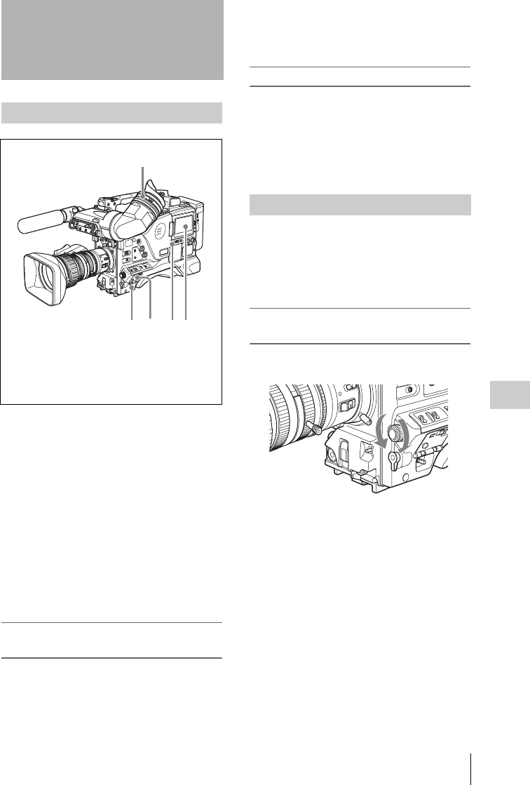
Menu Operations 163
Chapter 6 Menu Displays and Detailed Settings
To use the MENU ON/OFF switch, open the
cover of the menu operating section.
When the camcorder is powered on, set the
MENU ON/OFF switch to ON to display the
menu on the viewfinder screen and the LCD
monitor.
If this is the first time the menu has been used
after the camcorder has been powered on, the
USER menu is displayed. If the menu has been
used before, the last accessed page appears.
When the menu is not displayed on the LCD
monitor
Press the DISP SEL/EXPAND button below the
LCD monitor to select the CHAR display.
To clear the menu display from the
screen
Set the MENU ON/OFF switch to OFF. (When
the cover of the menu operating section is closed,
this switch is automatically set to OFF.)
When the DISPLAY of the DISPLAY/ASPECT
switch on the viewfinder is set to ON, the display
indicating the current status of the camcorder
appears on the viewfinder screen.
For details, see “Selecting the display items” on
page 171.
To display the TOP menu
With no menu displayed on the screen, hold down
the MENU knob and set the MENU ON/OFF
switch to ON.
Depending on the internal switch settings, display of
the TOP menu may be disabled. For details, refer to
the Maintenance Manual.
By pressing and turning the MENU knob, you can
set various menu items. In the remainder of this
section, the LCD monitor is generally shown as
an example of the menu display, but a similar
display also appears on the viewfinder screen.
To select the setting items and values on
the menu
Turn the MENU knob to select in the cases
explained below.
Menu Operations
Displaying menus
2354
1
1Viewfinder
2LCD monitor
3DISP SEL/EXPAND button
4MENU ON/OFF switch
5POWER switch
Basic menu operations
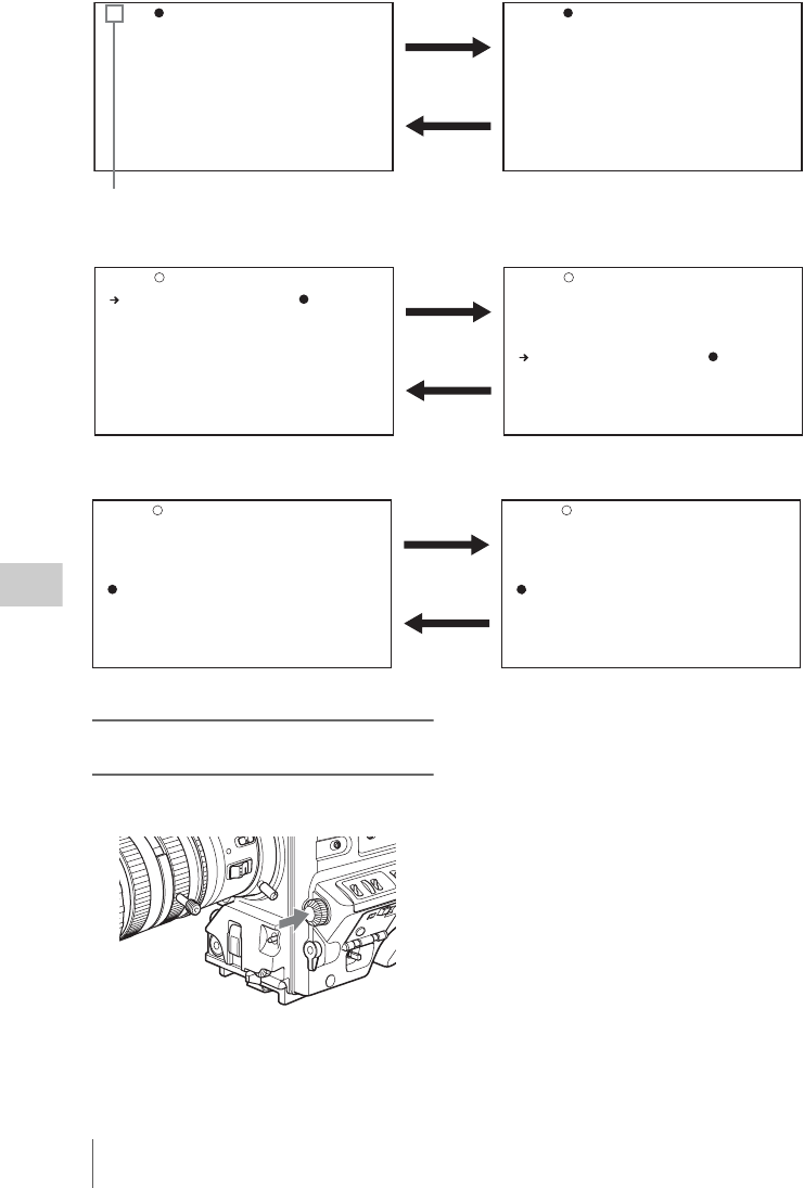
Menu Operations
164
Chapter 6 Menu Displays and Detailed Settings
To scroll pages
To select a menu or setting item
To change a setting value
To confirm the selection of a menu, a
setting item, or a setting value
Each time you press the MENU knob, the menu
display switches in the following sequence.
TOP?001 OUTPUT1
SDI OUT1 SELECT: OFF
SDI OUT2 SELECT: OFF
SDI OUT2 SUPER : OFF
TEST OUT SELECT: VBS
TEST OUT SUPER : OFF
TOP?005 REC FUNCTION
CACHE REC : OFF
When ? blinks, turn the MENU knob to switch pages.
TOP 001 OUTPUT1
SDI OUT1 SELECT: OFF
SDI OUT2 SELECT: OFF
SDI OUT2 SUPER : OFF
TEST OUT SELECT: VBS
TEST OUT SUPER : OFF
TOP 001 OUTPUT1
SDI OUT1 SELECT: OFF
SDI OUT2 SELECT: OFF
SDI OUT2 SUPER : OFF
TEST OUT SELECT: VBS
TEST OUT SUPER : OFF
When b appears, turn the MENU knob to move b up and down.
TOP 001 OUTPUT1
SDI OUT1 SELECT: OFF
SDI OUT2 SELECT: OFF
SDI OUT2 SUPER : OFF
TEST OUT SELECT:? VBS
TEST OUT SUPER : OFF
TOP 001 OUTPUT1
SDI OUT1 SELECT: OFF
SDI OUT2 SELECT: OFF
SDI OUT2 SUPER : OFF
TEST OUT SELECT:? Y
TEST OUT SUPER : OFF
When ? blinks, turn the MENU knob to change the setting (ON/OFF, value, etc.).
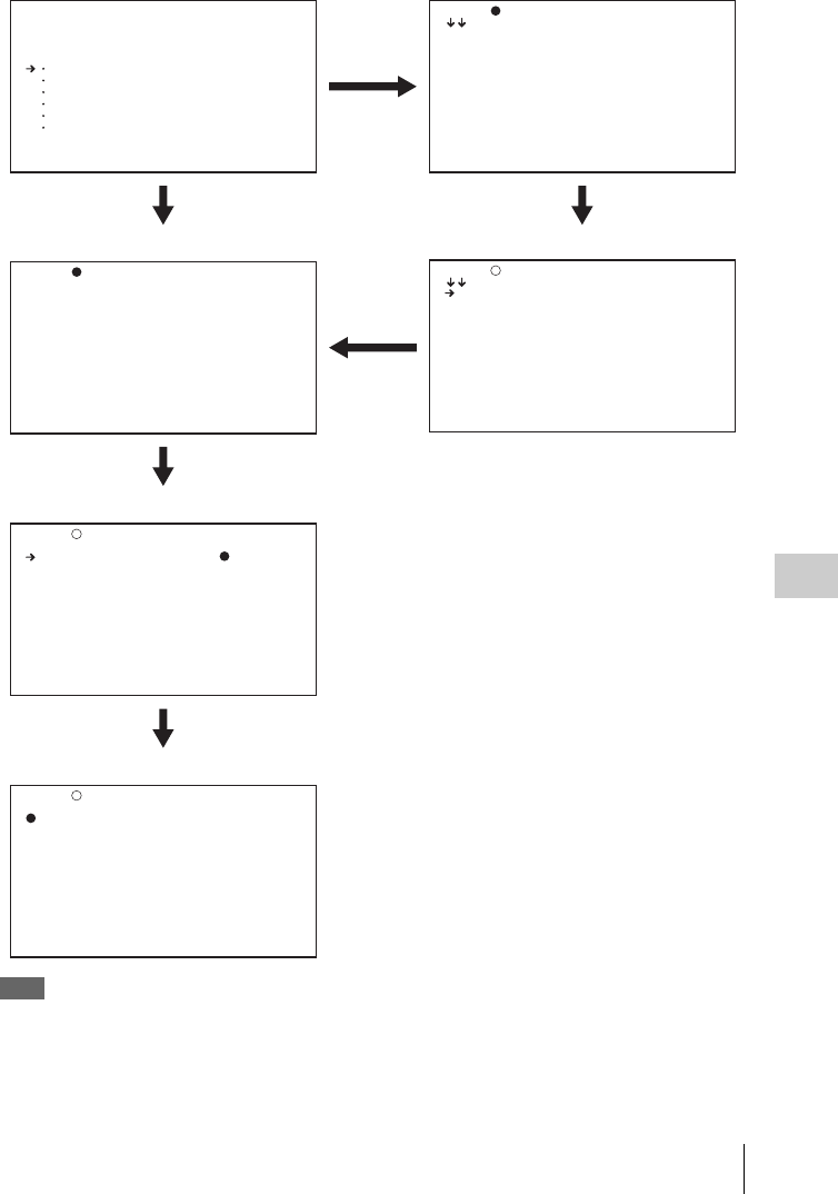
Menu Operations 165
Chapter 6 Menu Displays and Detailed Settings
Example: When using the OPERATION menu
Note
If the TOP menu has not been displayed since the
camcorder is powered on, “TOP” does not appear at the
upper right on the above screen, and you cannot go to the
TOP menu. In this case, follow the procedure in “To
display the TOP menu” (page 163).
<TOP MENU>
USER
USER MENU CUSTOMIZE
ALL
OPERATION
PAINT
MAINTENANCE
FILE
DIAGNOSIS
ADVANCED
TOP?000 CONTENTS
01.OUTPUT 1
02.OUTPUT 2
03.SUPERIMPOSE
04.LCD
05.REC FUNCTION
06.ASSIGNABLE SW
07.POWER SAVE
08.VF DISP 1
09.VF DISP 2
10.VF DISP 3
TOP 000 CONTENTS
01.OUTPUT 1
02.OUTPUT 2
03.SUPERIMPOSE
04.LCD
05.REC FUNCTION
06.ASSIGNABLE SW
07.POWER SAVE
08.VF DISP 1
09.VF DISP 2
10.VF DISP 3
TOP?001 OUTPUT1
SDI OUT1 SELECT: OFF
SDI OUT2 SELECT: OFF
SDI OUT2 SUPER : OFF
TEST OUT SELECT: VBS
TEST OUT SUPER : OFF
TOP001 OUTPUT1
SDI OUT1 SELECT:? OFF
SDI OUT2 SELECT: OFF
SDI OUT2 SUPER : OFF
TEST OUT SELECT: VBS
TEST OUT SUPER :
OFF
TOP 001 OUTPUT1
SDI OUT1 SELECT: OFF
SDI OUT2 SELECT: OFF
SDI OUT2 SUPER : OFF
TEST OUT SELECT: VBS
TEST OUT SUPER : OFF
TOP menu
If the menu
has not been
used
CONTENTS page
If the menu has
been used before
Menu selection mode Menu selection page
Setting item selection mode
Setting value selection mode
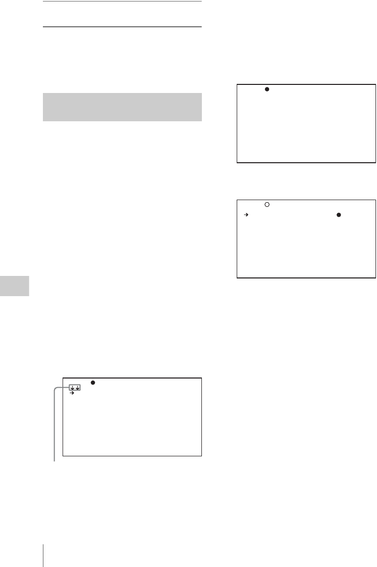
Menu Operations
166
Chapter 6 Menu Displays and Detailed Settings
To display the TOP menu when another
menu is displayed
Move b to “TOP” displayed at the top right of
each page of the menu, and press the MENU
knob. Or flick the CANCEL/PRST/ESCAPE
switch repeatedly to ESCAPE until the TOP
menu is displayed.
This section explains menu operations using the
USER menu as an example. The operations are
the same for the ALL, OPERATION, PAINT,
MAINTENANCE, and DIAGNOSIS menus.
For details about how to operate the USER MENU
CUSTOMIZE menu, see “Editing the USER menu”
(page 167).
1Set the MENU ON/OFF switch to ON.
Normally, the USER menu appears.
If it does not, turn the MENU knob to move
b to USER in the TOP menu, and press the
MENU knob.
If the USER menu has been used before, the
last accessed page appears. In this case, go to
step 2.
If this is the first time the USER menu has
been displayed, the CONTENTS page of the
USER menu appears. In this case, follow the
procedure below.
1Press the MENU knob. Then turn the
MENU knob to move b to the desired
page number.
2Press the MENU knob again.
The page selected in 1 is displayed.
Go to step 3.
When you set items on the ALL,
OPERATION, PAINT, MAINTENANCE,
FILE, and DIAGNOSIS menus, move b to
the menu that contains the desired item in the
TOP menu, and then press the MENU knob.
2Turn the MENU knob until the desired
page appears.
3Press the MENU knob.
b and z appear.
4Turn the MENU knob to move b to the
desired item, and then press the MENU
knob.
b changes to z, and z changes to ?.
5Turn the MENU knob to change the
setting.
Depending on the direction of turning the
knob, the setting value increases, decreases,
switches between ON and OFF, and so on.
To interrupt changing the settings
Set the MENU ON/OFF switch to OFF.
By setting the MENU ON/OFF switch to ON
again, the values that were displayed when
you interrupted the setting operations will
reappear so you can continue making
settings.
6Press the MENU knob.
z changes to b, and ? changes to z. The
selection is confirmed.
7To continue setting other items on the
same page, repeat steps from 4 to 6.
Using the USER menu (example
menu operation)
TOP?U00 CONTENTS
01.OUTPUT 1
02.OUTPUT 2
03.SUPERIMPOSE
04.LCD
05.REC FUNCTION
06.ASSIGNABLE SW
07.VF DISP 1
08.VF DISP 2
09.'!' LED
10.MARKER 1
This indicates that the menu
screen can be scrolled.
TOP?U05 REC FUNCTION
CACHE/INTVAL REC: OFF
DISC EXCHG CACHE: OFF
TOP
CACHE/INTVAL REC: OFF
DISC EXCHG CACHE: OFF
U05 REC FUNCTION

Menu Operations 167
Chapter 6 Menu Displays and Detailed Settings
8To end the menu operation, set the
MENU ON/OFF switch to OFF.
The menu disappears from the screen, and
the display indicating the current status of the
camcorder appears along the top and bottom
of the screen.
To cancel a change or return to the
standard settings
Note
Depending on the setting item, in some cases only the
function to return to the standard setting is valid.
1Before pressing the MENU knob in step
6 of the above procedure, flick the
CANCEL/PRST/ESCAPE switch to the
CANCEL/PRST position.
The message “CANCEL DATA OK?”
appears.
2Flick the CANCEL/PRST/ESCAPE
switch to the CANCEL/PRST position
again.
The message “CANCEL DATA” appears to
indicate that the change has been cancelled.
3To return to the standard settings after
pressing the MENU knob in step 6 of the
above procedure, flick the CANCEL/
PRST/ESCAPE switch to the
CANCEL/PRST position.
The message “PRESET DATA OK?”
appears on the screen.
4Flick the CANCEL/PRST/ESCAPE
switch to the CANCEL/PRST position
again.
This returns to the standard settings.
To move to another page
When ? appears in front of the page number
Turn the MENU knob to switch pages.
When nothing appears in front of the page
number
Turn the MENU knob to move b to the page
number, and press the MENU knob. Then turn the
MENU knob to switch pages.
The USER MENU CUSTOMIZE menu allows
you to configure a USER menu that consists only
of pages and items that you need by adding,
deleting or replacing the pages.
To add a new page
The USER MENU CUSTOMIZE menu allows
you to add a new page to the USER menu.
While the EDIT page contains factory-preset
items, the EDIT USER 1 to EDIT USER 19 pages
are all blank in their initial state. You can register
up to 10 items, including blank lines, on each of
these pages.
(How to select an item in the menu screen: Turn
the MENU knob to move b to the desired item.)
1Display the TOP menu (see page 163).
2Select USER MENU CUSTOMIZE,
and press the MENU knob.
If this is the first time the USER MENU
CUSTOMIZE menu has been displayed, the
CONTENTS page of the menu appears.
If the USER MENU CUSTOMIZE menu has
been used before, the last accessed page
appears.
3If the CONTENTS page is displayed,
press the MENU knob. Then select one
of EDIT USER 1 to EDIT USER 19, and
press the MENU knob.
TOP?U05 REC FUNCTION
CACHE/INTVAL REC: OFF
DISC EXCHG CACHE: OFF
Editing the USER menu
TOP?E00 CONTENTS
01.EDIT PAGE
02.EDIT USER 1
03.EDIT USER 2
04.EDIT USER 3
05.EDIT USER 4
06.EDIT USER 5
07.EDIT USER 6
08.EDIT USER 7
09.EDIT USER 8
10.EDIT USER 9

Menu Operations
168
Chapter 6 Menu Displays and Detailed Settings
If a different page other than the
CONTENTS page is displayed, turn the
MENU knob until the desired page appears,
then press the MENU knob.
Example: when the EDIT USER 9 page is
selected
4Press the MENU knob. Then select the
line where you want to add an item, and
press the MENU knob.
The EDIT FUNCTION page appears.
5Select INSERT, and press the MENU
knob.
The following menu appears.
6Add the items as follows.
1Press the MENU knob, scroll the page
until the desired item appears, and then
press the MENU knob again.
2Press the MENU knob again, select the
desired item, and then press the MENU
knob.
The EDIT USER 9 page appears again,
displaying the newly added item.
7Repeat steps 4 to 6 to add the remaining
items.
You can add up to 10 items on one page.
To delete items from a page by using the
CANCEL/PRST/ESCAPE switch
1Follow steps 1 to 3 in “To add a new
page” (page 167).
2Press the MENU knob. Then select the
item that you want to delete.
3Flick the CANCEL/PRST/ESCAPE
switch to the CANCEL/PRST position.
The message “DELETE ITEM OK?”
appears.
4Flick the CANCEL/PRST/ESCAPE
switch to the CANCEL/PRST position
again.
To delete items from a page by using the menu
1Follow steps 1 to 3 in “To add a new
page” (page 167).
2Press the MENU knob. Then select the
item that you want to delete, and press
the MENU knob.
The EDIT FUNCTION page appears.
3Select DELETE, and press the MENU
knob.
The previously displayed page appears
again, and the message “DELETE OK? YES
b NO” appears.
4Select YES, and press the MENU knob.
To replace items on a page
1Follow steps 1 to 3 in “To add a new
page” (page 167).
2Press the MENU knob. Then select the
item that you want to replace, and press
the MENU knob.
The EDIT FUNCTION page appears.
3Select MOVE, and press the MENU
knob.
The previously displayed page appears
again.
TOP E10 EDIT USER 9
ESC EDIT FUNCTION
INSERT
MOVE
DELETE
BLANK
TOP?P00 CONTENTS
01.OUTPUT 1
02.OUTPUT 2
03.SUPERIMPOSE
04.LCD
05.REC FUNCTION
06.ASSIGNABLE SW
07.POWER SAVE
08.VF DISP 1
09.VF DISP 2
10.VF DISP 3

Menu Operations 169
Chapter 6 Menu Displays and Detailed Settings
4Select the position to which you want to
move the item, and press the MENU
knob.
The item selected in step 2 moves to the
position that you selected in step 4.
To insert a blank line
1Follow steps 1 to 3 in “To add a new
page” (page 167).
2Press the MENU knob. Then select the
item that you want to replace, and press
the MENU knob.
The EDIT FUNCTION page appears.
3Select BLANK, and press the MENU
knob.
The previously displayed page appears
again, and a blank line is inserted above the
specified item.
Note
You cannot insert a blank line on a page where 10 items
have already been registered.
To add/delete/replace pages
You can add a new page to the USER menu,
delete a page from the USER menu, or replace
pages, using the EDIT PAGE of the USER
MENU CUSTOMIZE menu.
To add a page
(How to select an item in the menu screen: Turn
the MENU knob to move b to the desired item.)
1Display the TOP menu (see page 163).
2Select USER MENU CUSTOMIZE,
and press the MENU knob.
If this is the first time the USER MENU
CUSTOMIZE menu has been displayed, the
CONTENTS page appears. If the menu has
been used before, the last accessed page
appears.
3If the CONTENTS page is displayed,
press the MENU knob. Then select
EDIT PAGE, and press the MENU
knob.
If a different page is displayed, turn the
MENU knob until the EDIT PAGE screen
appears.
The EDIT PAGE appears.
4Press the MENU knob. Then select the
position where you want to add the
page, and press the MENU knob.
The EDIT FUNCTION page appears.
5Select INSERT, and press the MENU
knob.
The CONTENTS page appears.
6Select the desired page, and press the
MENU knob.
The number and name of the page selected in
step 6 is added above the item selected in
step 4.
To cancel adding a page
Before pressing the MENU knob in step 6,
select ESC at the top right of the screen, and
press the MENU knob.
The EDIT PAGE screen appears again.
To delete a page by using the CANCEL/PRST/
ESCAPE switch
1Follow steps 1 to 3 in “To add a page”
(page 169).
2Press the MENU knob. Then select the
page that you want to delete.
3Flick the CANCEL/PRST/ESCAPE
switch to the CANCEL/PRST position.
The message “DELETE PAGE OK?”
appears.
4Flick the CANCEL/PRST/ESCAPE
switch to the CANCEL/PRST position
again.
To delete a page by using the menu
1Follow steps 1 to 3 in “To add a page”
(page 169).
TOP?E01 EDIT PAGE
01.OUTPUT 1
02.OUTPUT 2
03.SUPERIMPOSE
04.LCD
05.REC FUNCTION
06.ASSIGNABLE SW
07.VF DISP 1
08.VF DISP 2
09.'!' LED
10.MARKER 1

Menu Operations
170
Chapter 6 Menu Displays and Detailed Settings
2Press the MENU knob. Then select the
page that you want to delete, and press
the MENU knob.
The EDIT FUNCTION page appears.
3Select DELETE, and press the MENU
knob.
The previously displayed page appears
again, and the message “DELETE OK? YES
b NO” appears at the upper right.
4Select YES, and press the MENU knob.
To replace pages
1Follow steps 1 to 3 in “To add a page”
(page 169).
2Press the MENU knob. Then select the
page that you want to move, and press
the MENU knob.
The EDIT FUNCTION page appears.
3Select MOVE, and press the MENU
knob.
The previous screen appears again.
4Select the position to which you want to
move the page, and press the MENU
knob.
The page selected in step 2 is moved to the
position.
To rename pages
The names of pages (USER 1 to USER 19)
created with EDIT USER 1 to EDIT USER 19
can be changed. (The maximum name length is
15 characters.)
Note
The ASSIGN ITEM SEL page cannot be renamed.
1Display the EDIT PAGE NAME1 or
EDIT PAGE NAME2 of the USER
MENU CUSTOMIZE menu.
EDIT PAGE NAME1: To rename USER1
to USER10
EDIT PAGE NAME2: To rename USER11
to USER19
For details on menu operations, see “Basic
menu operations” on page 163.
2Select the page that you want to rename
(USER 1 to USER 19), and press the
MENU knob.
A character table appears.
3Follow steps 3 and 4 described in
“Setting the shot ID” on page 175 to
enter characters.
4When you have finished entering the
name, turn the MENU knob to move x
to END, and press the MENU knob.
The entered name is now displayed.
You can return all settings in the USER menu to
standard settings.
(How to select an item in the menu screen: Turn
the MENU knob to move b to the desired item.)
Resetting USER menu settings to
the standard settings
TOP E22 EDIT PAGE NAME1
USER1 : USER 1
USER2 : USER 2
USER3 : USER 3
USER4 : USER 4
USER5 : USER 5
USER6 : USER 6
USER7 : USER 7
USER8 : USER 8
USER9 : USER 9
USER10: USER 10
TOP E22 EDIT PAGE NAME1
USER1 :?
USER2 : USER 2
USER3 : USER 3
USER4 : USER 4
USER5 : USER 5
!#$%&'()*+,-./012345678
9:;<=>?@ABCDEFGHIJKLMNOP
QRSTUVWXYZ[©]abcdefghijk
lmnopqrstuvwxyz~
INS DEL RET ESC END
TOP E22 EDIT PAGE NAME1
USER1 : SPECIAL ITEM
USER2 : USER 2
USER3 : USER 3
USER4 : USER 4
USER5 : USER 5
USER6 : USER 6
USER7 : USER 7
USER8 : USER 8
USER9 : USER 9
USER10: USER 10
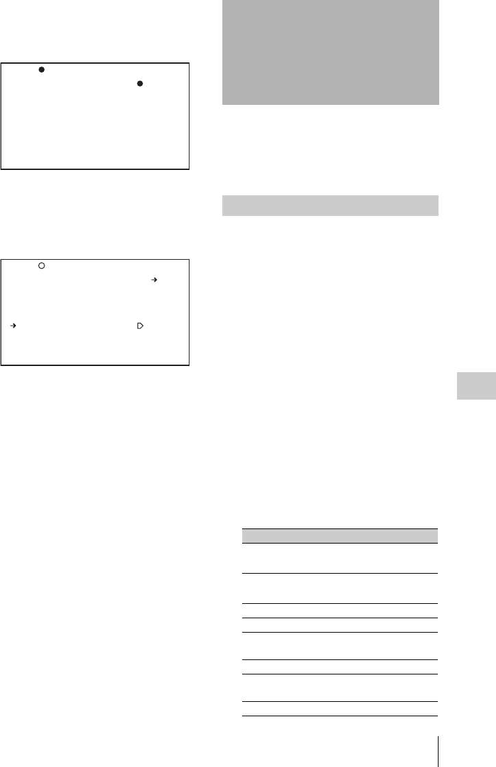
Setting the Status Display on the Viewfinder Screen and the LCD Monitor 171
Chapter 6 Menu Displays and Detailed Settings
1Display the USER FILE page of the
FILE menu, and press the MENU knob.
For details on menu operations, see “Basic
menu operations” on page 163.
2Press the MENU knob, then select
USER PRESET, and press the MENU
knob.
The message “PRESET OK? YES b NO”
appears.
3Select YES, and press the MENU knob.
The message “COMPLETE” appears, and
the settings for all items in the USER menu
are reset to the standard settings.
This section explains the menu settings for the
display of the viewfinder screen. These settings
are also used for the display of the LCD monitor
in the same way.
To select the items to be displayed on the
viewfinder screen (with the viewfinder
DISPLAY of the DISPLAY/ASPECT switch set
to ON) and the LCD monitor, use the
VF DISP 1, VF DISP 2, and VF DISP 3 pages of
the OPERATION menu.
(How to select an item in the menu screen: Turn
the MENU knob to move b to the desired item.)
1Display the VF DISP 1, VF DISP 2, or
VF DISP 3 page of the OPERATION
menu, and press the MENU knob.
For details on menu operations, see “Basic
menu operations” on page 163.
2Select the desired setting item, and
press the MENU knob.
On the VF DISP 1, VF DISP 2, and VF DISP
3 pages, you can select any of the following
items to turn its display on or off.
VF DISP 1 page
TOP?F01 USER FILE
USER FILE LOAD : EXEC
USER FILE SAVE : EXEC
F.ID :
ssssssssssssssss
USER PRESET : EXEC
TOP F01 USER FILE
PRESET OK? YES NO
USER FILE LOAD : EXEC
USER FILE SAVE : EXEC
F.ID :
ssssssssssssssss
USER PRESET : EXEC
Setting the Status
Display on the
Viewfinder Screen and
the LCD Monitor
Selecting the display items
Item Description
VF DISP Turning on or off the
viewfinder display a)
VF DISPLAY
MODE
Selecting the display
mode b)
DISP EXTENDER Extender indicator
DISP FILTER Types of the ND filter
DISP WHITE White balance memory
indicator
DISP GAIN Gain indicator
DISP SHUTTER Shutter speed and ECS
mode indicator
DISP AUDIO Audio level indicator

Setting the Status Display on the Viewfinder Screen and the LCD Monitor
172
Chapter 6 Menu Displays and Detailed Settings
a) The viewfinder display can be also turned on or
off by using the DISPLAY of the DISPLAY/
ASPECT switch on the viewfinder.
b) For detailed information on the display mode, see
“Change confirmation/adjustment progress
messages” (page 172).
VF DISP 2 page
a) When an Anton Bauer battery system or a BP-
GL65/GL95 battery pack is installed, the
remaining battery power is shown as a
percentage value (%) according to the setting of
this item.
INT: When one of the above batteries is
installed, the remaining power is shown as a
percentage value (%) when there is a change
in the value or when the power is low.
AUTO: The remaining power is shown as a
percentage value (%) when one of the above
batteries is installed. Otherwise the voltage
(VOLT) is displayed continuously.
VOLT: The voltage (VOLT) is displayed
continuously.
VF DISP 3 page
a) This makes it possible to display settings that
include reference settings, stored with STORE
ALL PRESET or other functions, as absolute
values.
3Turn the MENU knob to select the
desired setting (ON, OFF, or value), and
press the MENU knob.
4Repeat steps 2 and 3 until you have set
all of the desired items.
You can limit or suppress the messages that give
details of setting changes and adjustment
progress and results by setting a display mode.
The conditions under which messages are
displayed and their correspondence with the
display mode are as follows:
Y: Message is displayed.
N: Message is not displayed.
DISP DISC Remaining disc capacity
indicator
DISP IRIS Iris opening indicator
Item Description
DISP ZOOM Zoom position indicator
DISP COLOR
TEMP
Displays the color
temperature.
DISP BATT
REMAIN a)
Displays the battery
voltage/remaining capacity
of an internal battery pack
or an external battery
connected to the DC IN
connector.
DISP DC IN Displayed when the power
is supplied from an external
battery connected to the
DC IN connector.
DISP 16:9/4:3
ID
Displays the video aspect
ratio (16:9 or 4:3). (When
the CBKZ-MD01 is
installed.)
DISP WRR RF
LVL
Displays the reception level
of the wireless microphone.
DISP REC
FORMAT
Displays the recording
format.
DISP CLIP
NO(PB)
Displays clip information.
DISP
TIMECODE
Displays the timecode.
Item Description
Item Description
LOW LIGHT Turns on and off the on-
screen warning that the
average level of the video has
dropped beneath a set level.
LOW LIGHT
LEVEL
Sets the LOW LIGHT
threshold value.
VF BATT
WA RN I NG
Specifies the remaining
battery capacity level that
starts the flashing warning in
the viewfinder.
ABSOLUTE
VA L U E
Turns on and off the mode
that displays numeric menu
settings as absolute values. a)
Change confirmation/adjustment
progress messages
Message display
condition
Message Display
mode
setting
1 2 3
When the filter
selection has been
changed
FILTER: n (where
n = 1, 2, 3, 4)
NNY

Setting the Status Display on the Viewfinder Screen and the LCD Monitor 173
Chapter 6 Menu Displays and Detailed Settings
a) This is also displayed for about 3 seconds when the
SHUTTER selector is set to ON.
Changing the display mode
1Display the VF DISP 1 page of the
OPERATION menu, and press the
MENU knob.
For details on menu operations, see “Basic
menu operations” on page 163.
2Select VF DISP MODE, and press the
MENU knob.
3Select the desired display mode, and
press the MENU knob.
Switch the display of the center and safety zone
markers on or off, and select whether the area
indicated by the safety zone marker is 80%, 90%,
92.5%, or 95% of the screen area.
(How to select an item in the menu screen: Turn
the MENU knob to move b to the desired item.)
1Display the MARKER 1 or MARKER 2
page of the OPERATION menu, and
press the MENU knob.
For details on menu operations, see “Basic
menu operations” on page 163.
2Select the desired item, and press the
MENU knob.
You can set the following items on the
MARKER 1 and MARKER 2 pages.
MARKER 1 page
a) The ASPECT MASK setting affects the
viewfinder and LCD monitor display. In the
following cases, it also affects the VBS signal.
• When TEST OUT SELECT on the OUTPUT 1
page is set to VBS.
• When both TEST OUT SUPER on the
OUTPUT 1 page and SUPER(MARKER) on
the SUPER IMPOSE page are set to ON.
ASPECT MASK is ignored for displays in the
viewfinder when the following are true.
• TEST OUT SELECT on the OUTPUT 1 page
is set to HD-Y, and a cable is connected to the
TEST OUT connector.
• TEST OUT SELECT on the OUTPUT 1 page
is set to HD-Y, and TEST OUT SAVE on the
POWER SAVE page is set to OFF.
When the gain
setting has been
changed
GAIN: n (where n
= –6dB, –3dB, 0dB,
3dB, 6dB, 9dB,
12dB, 18dB, 24dB,
30dB, 36dB, 42dB)
NNY
When the setting of
the WHITE BAL
switch has been
changed
WHITE: n (where n
= A CH, B CH,
PRESET) or ATW:
RUN
NNY
When the
OUTPUT/DCC
switch has been set
to DCC ON or OFF
DCC: ON (or OFF) N Y Y
When the shutter
speed and mode
setting has been
changed a)
:SHUTTER:
1/100 (or 1/125,
1/250, 1/500, 1/
1000, 1/2000, ECS)
NYY
When the black or
white balance has
been adjusted
E.g. AWB : OK N Y Y
Setting the marker display
Message display
condition
Message Display
mode
setting
1 2 3
Item Description
MARKER To hide all markers, set to
“OFF”.
CENTER To display the center marker,
set to “ON”.
CENTER
MARK
Selects the position of the
center marker.
SAFETY
ZONE
To display the safety zone, set
to “ON”.
SAFETY
AREA
Selects the safety zone range
(80%, 90%, 92.5% or 95%).
ASPECT To display the aspect marker,
set to “ON”.
ASPECT
SELECT
Selects the aspect mode (15:9/
14:9/13:9/4:3/1.85/2.35).
ASPECT
MASK a)
To make the areas out of the
selected aspect marker dimmer,
set to “ON”.
ASPECT
MASK LVL
To set the mask level, when the
ASPECT MASK is set to
“ON”.
100 %
MARKER
To display the effective pixel
area, set to “ON”.

Setting the Status Display on the Viewfinder Screen and the LCD Monitor
174
Chapter 6 Menu Displays and Detailed Settings
Note
The four items ASPECT, ASPECT SELECT,
ASPECT MASK, and ASPECT MASK LVL are
ignored when the recording format is IMX50/40/30
or DVCAM and the aspect ratio is 4:3.
MARKER 2 page
3Turn the MENU knob to change the
setting, and press the MENU knob.
4Repeat steps 2 and 3 until you have set
all of the desired items.
You can make settings for viewfinder screen
display functions.
(How to select an item in the menu screen: Turn
the MENU knob to move b to the desired item.)
1Display the VF SETTING page of the
OPERATION menu, and press the
MENU knob.
For details on menu operations, see “Basic
menu operations” on page 163.
2Select the desired item, and press the
MENU knob.
You can set the following items on the VF
SETTING page.
a) When you use the viewfinder which is not
equipped with the ZEBRA switch, turns the
display on or off using this item. When you use
the viewfinder with the ZEBRA switch, the most
recent operation of the ZEBRA switch and this
menu operation is effective.
3Turn the MENU knob to change the
setting, and press the MENU knob.
4Repeat steps 2 and 3 until you have set
all of the desired items.
In the SHOT DISP page of the USER menu, you
can select which shot data is recorded
superimposed on the color bars. You can also
select which of the shot IDs (1 to 4) set in the
SHOT DATA page is recorded superimposed on
the picture.
Item Description
USER BOX Turns the display of the box
cursor on and off.
USER BOX
WIDTH
Sets the width of the box
cursor (distance from center to
left or right edge).
USER BOX
HEIGHT
Sets the height of the box
cursor (distance from center to
top or bottom edge).
USER BOX
H POS
Sets the horizontal position of
the center of the box cursor.
USER BOX
V POS
Sets the vertical position of the
center of the box cursor.
CENTER H
POS
Sets the horizontal position of
the center marker.
CENTER V
POS
Sets the vertical position of the
center marker.
ASPECT
SAFE ZONE
Turns the display of the aspect
safety zone on and off.
ASPECT
SAFE AREA
Selects the range of the aspect
safety zone (80%/90%/92.5%/
95%).
Setting the viewfinder
Item Description
ZEBRA Turns the zebra display on or
off. a)
ZEBRA
SELECT
Selects ZEBRA 1, ZEBRA 2 or
BOTH.
ZEBRA 1
DET. LVL
Adjusts the level of the zebra 1
(20% to 70% to 107%) display.
ZEBRA 1
APT. LVL
Adjusts the aperture level of the
zebra 1 display. (1% to 10% to
20%)
ZEBRA 2
DET. LVL
Adjusts the level of the zebra 2
(52% to 100% to 109%)
display.
VF DETAIL
LEVEL
Adjusts the sharpness of the
viewfinder (–99 to 99).
VF ASPECT
(SD)
Specifies whether to set the
viewfinder screen and LCD
monitor aspect ratio
automatically or to set it to 16:9
when the IMX50/40/30 or
DVCAM recording format is
selected.
When “16:9” is selected, then
the screen is always displayed
as a 16:9 screen (before being
cut out to 4:3), even when
ASPECT RATIO (SD) is set to
“4:3”.
Recording shot data
superimposed on the color bars

Setting the Status Display on the Viewfinder Screen and the LCD Monitor 175
Chapter 6 Menu Displays and Detailed Settings
(How to select an item in the menu screen: Turn
the MENU knob to move b to the desired item.)
1Display the SHOT DISP page of the
OPERATION menu, and press the
MENU knob.
For details on menu operations, see “Basic
menu operations” on page 163.
2Select the desired item, and press the
MENU knob.
You can set the following items on the SHOT
DISP page.
a) To carry out superimposed recording, select the
SHOT ID number (1 to 4). Not to carry out
superimposed recording, select “OFF”.
3Turn the MENU knob to select whether
or not to record the selected item
superimposed on the color bars or the
SHOT ID number, and press the
MENU knob.
4Repeat steps 2 and 3 until you have set
all of the desired items.
To carry out superimposed recording
To actually record the items selected for
superimposed recording on the SHOT DISP page,
set the OUTPUT/DCC switch to BARS, DCC
OFF.
The items selected for superimposed recording
appear on the screen and are recorded
superimposed on the color bars.
Example display: when SHOT DATA is set to
ON
You can set a shot ID of up to 12 alphanumeric
characters, spaces, and symbols.
When the OUTPUT/DCC switch is set to BARS,
DCC OFF, this shot ID is output with the color
bar signal. You can set four shot IDs (ID-1 to
ID-4).
Note
When the menu is displayed, the shot ID is not displayed
even if the color bar signal is output.
(How to select an item in the menu screen: Turn
the MENU knob to move b to the desired item.)
1Display the SHOT ID page of the
OPERATION menu, and press the
MENU knob.
For details on menu operations, see “Basic
menu operations” on page 163.
Item Description
SHOT
DATE
Selects whether or not the shot
data is superimposed (ON or
OFF).
SHOT
TIME
Selects whether or not shot time
is superimposed (ON or OFF).
SHOT
MODEL
NAME
Selects whether or not the model
name is superimposed (ON or
OFF).
SHOT
SERIAL
NO.
Selects whether or not the serial
number is superimposed (ON or
OFF).
SHOT ID
SEL
Selects whether or not the shot
ID set on the SHOT ID page is
superimposed. a)
SHOT 16:9
CHARA
Turns the following function on
and off: When displaying aspect
ratio 4:3 video, record
superimposed “16:9” in the
locations where 16:9 video is
cut.
SHOT
BLINK
CHARA
Selects whether or not the
blinking * is superimposed (ON
or OFF).
Setting the shot ID
08/03/15
TOP 017 SHOT ID
ID-1 :
ssssssssssss
ID-2 :
ssssssssssss
ID-3 :
ssssssssssss
ID-4 :
ssssssssssss
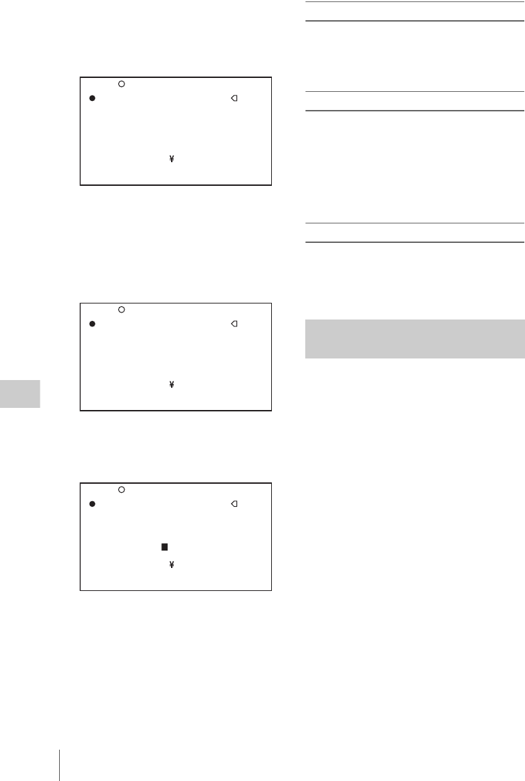
Setting the Status Display on the Viewfinder Screen and the LCD Monitor
176
Chapter 6 Menu Displays and Detailed Settings
2Select one of ID-1 to ID-4, and press the
MENU knob.
A x mark appears over the first character
position in the string, and characters can now
be input.
3Enter or change the shot ID.
When you are entering the whole shot ID, go
to 2.
1Turn the MENU knob to move the x
mark to the character which you want
to change, then press the MENU knob.
2Turn the MENU knob until the x mark
moves to the character position that
you want to select, then press the
MENU knob.
4Repeat step 3 for each of the remaining
characters.
5When the input is complete, turn the
MENU knob to move the x mark over
END, then press the MENU knob.
This ends the input, and returns to the
original SHOT ID page.
To insert a space
In step 3 above, move the x mark over INS, and
press the MENU knob.
To cancel inserting a space, move the x mark
over RET, then press the MENU knob.
To delete a character
In step 3 of “Setting the shot ID” (page 175),
move the x mark over DEL, and press the
MENU knob.
This deletes the character under the x mark in the
shot ID row.
To cancel deleting the character, move the x
mark over RET, and press the MENU knob.
To cancel changing shot ID
Before executing step 5 of “Setting the shot ID”
(page 175), move the b mark over ESC, then
press the MENU knob or flick the CANCEL/
PRST/ESCAPE switch to ESCAPE.
You can confirm the settings or status of the
camcorder on the LCDs by displaying the
following four screen.
ABNORMAL <!> screen
This window allows you to confirm why the !
(warning) indicator lights in the viewfinder.
You can use the ‘!’ LED page of the
OPERATION menu to set whether or not the !
(warning) indicator lights.
SYSTEM screen
This screen displays information such as the
system frequency, the recording format, whether
output from the TEST OUT connector is on or
off, and the type of output signal.
FUNCTION screen
This screen displays the functions assigned to the
ASSIGN switches, the detection level, and other
information.
AUDIO STATUS screen
This screen allows you to confirm the following
items related to audio.
• Audio bit rate
• Setting condition of DF/NDF
• Type of front microphone
ID-1 :?
x
ID-2 :
ssssssssssss
ID-3 :
ssssssssssss
ID-4 :
ssssssssssss
!#$%&'()*+,-./012345678
9:;<=>?@ABCDEFGHIJKLMNOP
QRSTUVWXYZ[ ]abcdefghijk
lmnopqrstuvwxyz~
INS DEL RET ESC END
TOP 017 SHOT ID
ID-1 :?
x
ID-2 :
ssssssssssss
ID-3 :
ssssssssssss
ID-4 :
ssssssssssss
!#$%&'()*+,-./012345678
9:;<=>?@ABCDEFGHIJKLMNOP
QRSTUVWXYZ[ ]abcdefghijk
lmnopqrstuvwxyz~
INS DEL RET ESC END
TOP 017 SHOT ID
ID-1 :?+
ID-2 :
ssssssssssss
ID-3 :
ssssssssssss
ID-4 :
ssssssssssss
!#$%&'()*+,-./012345678
9:;<=>?@ABCDEFGHIJKLMNOP
QRSTUVWXYZ[ ]abcdefghijk
lmnopqrstuvwxyz~
INS DEL RET ESC END
TOP 017 SHOT ID
Displaying the status
confirmation screens

Adjustments and Settings From Menus 177
Chapter 6 Menu Displays and Detailed Settings
• Type of input signal to audio channels 1 to 4
• Input level of audio channels 1 to 4
You can use the SET STATUS page of the
OPERATION menu to set whether or not the
status confirmation screens are displayed.
To display the status confirmation
screens
You can use the CANCEL/PRST/ESCAPE
switch as the STATUS ON/SEL/OFF switch
when the MENU ON/OFF switch is set to OFF
(when the cover of the menu operating section is
closed, OFF is automatically selected).
To disable display of the status
confirmation screens
(How to select an item in the menu screen: Turn
the MENU knob to move b to the desired item.)
1Display the SET STATUS page of the
OPERATION menu, and press the
MENU knob.
For details on menu operations, see “Basic
menu operations” on page 163.
2Select the desired item, and press the
MENU knob.
You can set the following items on the SET
STATUS page.
3Turn the MENU knob to change the
setting, and press the MENU knob.
4Repeat steps 2 and 3 until you have set
all of the desired items.
You can set the gain values for the L, M, and H
positions of the GAIN selector, which switches
the gain of the video amplifier.
(How to select an item in the menu screen: Turn
the MENU knob to move b to the desired item.)
1Display the GAIN SW page of the
OPERATION menu, and press the
MENU knob.
For details on menu operations, see “Basic
menu operations” on page 163.
2Select the item for the switch position,
then press the MENU knob.
You can set the following items on the GAIN
SW page.
Item Description
STATUS
ABNORMAL
Selects whether or not the
ABNORMAL window is
displayed (ON or OFF).
STATUS
SYSTEM
Displays (ON) or hides
(OFF) the SYSTEM menu.
STATUS
FUNCTION
Selects whether or not the
FUNCTION window is
displayed (ON or OFF).
STATUS
AUDIO
Selects whether or not the
STATUS AUDIO window is
displayed (ON or OFF).
Adjustments and
Settings From Menus
Setting gain values for the GAIN
selector positions
Item Description
GAIN
LOW
Sets the gain value
corresponding to the L position
of the GAIN selector.
GAIN MID Sets the gain value
corresponding to the M position
of the GAIN selector.
GAIN
HIGH
Sets the gain value
corresponding to the H position
of the GAIN selector.
GAIN
TURBO
Sets the gain value
corresponding to TURBO GAIN
function.

Adjustments and Settings From Menus
178
Chapter 6 Menu Displays and Detailed Settings
3Turn the MENU knob to select the gain
value, and press MENU knob.
Any of –6, –3, 0, 3, 6, 9, 12, 18, 24, 30, 36 or
42 dB can be set for each of the L, M, H, and
TURBO positions, in any sequence.
4Repeat steps 2 and 3 until you have set
all of the desired items.
(How to select an item in the menu screen: Turn
the MENU knob to move b to the desired item.)
1Display the OUTPUT 1 page of the
OPERATION menu, and press the
MENU knob.
For details on menu operations, see “Basic
menu operations” on page 163.
2Select the desired item, and press the
MENU knob.
You can set the following items on the
OUTPUT 1 page.
3Turn the MENU knob to change the
setting, and press the MENU knob.
4Repeat steps 2 and 3 until you have set
all of the desired items.
You can assign the desired function to any of the
ASSIGN switches.
(How to select an item in the menu screen: Turn
the MENU knob to move b to the desired item.)
1Display the ASSIGNABLE page of the
OPERATION menu, and press the
MENU knob.
TURBO
SW IND
OFF: When you operate the
GAIN selector after
pressing the button to which
the TURBO GAIN function
has been assigned once, the
video gain is changed
according to the GAIN
selector operation.
ON: When the video gain is
boosted to the video gain to
the value preset by pressing
the button to which the
TURBO GAIN function has
been assigned once, the
video gain is not changed
even if you operate the
GAIN selector, until you
press the button once more.
SHOCK-
LESS
GAIN
Turns shockless gain on or off.
Selecting the output signals
Item Description Item Setting
SDI OUT 1
SELECT
Selects the signal output from
the SDI OUT1 connector.
OFF: Do not output video.
HD-SDI: Output HD-SDI.
SD-SDI: Output SD-SDI
SDI OUT 2
SELECT
Selects the signal output from
the SDI OUT2 connector.
OFF: Do not output video.
HD-SDI: Output HD-SDI.
SD-SDI: Output SD-SDI
SDI OUT 2
SUPER
Selects whether to superimpose
(ON) or not superimpose (OFF)
text information on the signal
output from the SDI OUT2
connector.
TEST OUT
SELECT
Selects the output signal from
the TEST OUT connector.
VBS: Output composite video
signal. When you select
VBS, connect to the
VIDEO IN connector of
your monitor.
Y: Output HD-Y signal.
R/G/B: Output HD RGB
signal.
LCD: Output a signal like the
display in the LCD
monitor.
TEST OUT
SUPER
Selects whether to superimpose
(ON) or not superimpose (OFF)
text information on the signal
output from the TEST OUT
connector.
Assigning functions to ASSIGN
switches

Adjustments and Settings From Menus 179
Chapter 6 Menu Displays and Detailed Settings
For details on menu operations, see “Basic
menu operations” on page 163.
You can assign functions by using the
following items.
2Select the desired switch or button, and
press the MENU knob.
A selection screen for the selected switch or
button appears. You can use these screens to
assign one of the following functions.
Functions to be assigned to the ASSIGN 1/
3/4 (push-type) switch, COLOR TEMP.
button, or RET button on the lens
Item Description
ASSIGN SW
<1>
Assigns the function to
ASSIGN 1 (push-type)
switch.
ASSIGN SW
<2>
Assigns the function to
ASSIGN 2 (slide-type)
switch.
ASSIGN SW
<3>
Assigns the function to
ASSIGN 3 (push-type)
switch.
ASSIGN SW
<4>
Assigns the function to
ASSIGN 4 (push-type)
switch.
ASSIGN SW
<RET>
Assigns the function to RET
button on the lens.
COLOR TEMP
SW
Assigns the function to
COLOR TEMP. button.
Function Description
OFF Assigns no function.
FRONT MIC Assigns the function that
switches between stereo and
monaural when a stereo
microphone is connected.
PICTURE
CACHE
Assigns execution of
recording in picture cache
mode.
SUPER
(VFDISP&
MENU)
Assigns a mixing switch
function that selects mixing
or no mixing of
superimposed viewfinder
and menu text data into the
video signals output from the
SDI OUT 2 or TEST OUT
connector, when SDI OUT 2
SUPER or TEST OUT
SUPER on the OUTPUT 1
page of the OPERATION
menu are set to ON.
MARKER Assigns the function that
displays or hides all
markers. a)
RETAKE b) Assigns the function that
deletes the last recorded clip.
ATW Assigns the function that
turns auto tracing white
balance ON and OFF.
RETURN
VIDEO
Assigns the function that
displays in the viewfinder
the HD-Y (1080i) signal
input to the GENLOCK IN
connector. c)
LENS RET Assigns the functions
executed by the RET button
on the lens (recording review
and so on).
REC SWITCH Assigns the function that
starts and stops recording.
TURBO
SWITCH
Assigns the turbo gain
function.
ZEBRA Assigns the zebra pattern
display function.
FREEZE MIX Assigns the function that
mixes a still picture
(monochrome) and camera
video (color) (effective for
framing shots).
COLOR TEMP
SW 3200K
Assigns the function that
switches the white balance to
3200K.
COLOR TEMP
SW 4300K
Assigns the function that
switches the white balance to
4300K.
COLOR TEMP
SW 5600K
Assigns the function that
switches the white balance to
5600K.
COLOR TEMP
SW 6300K
Assigns the function that
switches the white balance to
6300K.
ELECTRICAL
CC
Assigns the function that
switches between electrical
CC filters (3200K/4300K/
5600K/6300K).
CC 5600K Assigns the function that
applies an electrical 5600 K
filter.
Function Description

Adjustments and Settings From Menus
180
Chapter 6 Menu Displays and Detailed Settings
a) Even when the MARKER item is set to OFF on
the MARKER page of the USER menu, the
ASSIGN 1/3/4 switches allow you to display or
not to display all markers.
b) This function cannot be assigned to the RET
button on the lens.
c) Even if the RETURN VIDEO item is set to OFF
on the ASSIGNABLE SW page of the
OPERATION menu, you can use this switch to
display the image of the return video signal on
the viewfinder.
d) Only the Assign 3 SEL and Assign 4 SEL screens
appear.
e) Video momentarily becomes black and audio is
momentarily muted when the digital extender is
switched on and off.
f) This does not appear if nothing is assigned in the
Assign menu.
Functions to be assigned to the ASSIGN 2
(slide-type) switch
ZOOM TELE/
WIDE d)
For use with a lens that
supports serial
communications, assign the
ZOOM TELE setting to
ASSIGN 3, and the WIDE
setting to ASSIGN 4.
ZOOM WIDE/
TELE d)
For use with a lens that
supports serial
communications, assign the
ZOOM WIDE setting to
ASSIGN 3, and the TELE
setting to ASSIGN 4.
SHOT MARK1 Assigns the function that
records a SHOT MARK 1
essence mark.
SHOT MARK2 Assigns the function that
records a SHOT MARK 2
essence mark.
CLIP FLAG
OK
Assign the functions that set
or clear OK, NG, and KEEP
flags during recording or
playback.
CLIP FLAG
NG
CLIP FLAG
KEEP
FOCUS MAG Assigns the function that
magnifies the central part of
the viewfinder picture, for
easier focus adjustment.
(This function does not
affect recorded video or
other signal output.)
DIGITAL
EXTENDER
e)
Assigns the function that
electronically magnifies the
central part of the picture.
(All video output is
magnified, including
recorded video.)
UA01 to
UA10 f)
Assigns the items assigned
in the ASSIGN SEL menu.
Function Description
Function Content
OFF Assigns no function.
FRONT MIC Assigns the function that
switches between stereo and
monaural when a stereo
microphone is connected.
PICTURE
CACHE
Assigns execution of
recording in picture cache
mode.
SUPER
(VFDISP&M
ENU)
Assigns a mixing switch
function that selects mixing or
no mixing of superimposed
viewfinder and menu text data
into the video signals output
from the SDI OUT 2 or TEST
OUT connector, when SDI
OUT 2 SUPER or TEST OUT
SUPER on the OUTPUT 1
page of the OPERATION
menu are set to ON.
MARKER Assigns the function that
displays or hides all
markers. a)
REC VIDEO
SOURCE
Switches the recording target
video between the video shot
by the camera and the video
input from an external device
(VBS or SD-SDI/HD-SDI). b)
ZEBRA Assigns the zebra pattern
display function.
FREEZE MIX Assigns the function that
mixes a still picture
(monochrome) and camera
video (color) (effective for
framing shots).
DIGITAL
EXTENDER
c)
Assigns the function that
electronically magnifies the
central part of the picture. (All
video output is magnified,
including recorded video.)
UA01 to
UA10 d)
Assigns the items assigned in
the ASSIGN SEL menu.

Adjustments and Settings From Menus 181
Chapter 6 Menu Displays and Detailed Settings
a) Even when the MARKER item is set to OFF on
the MARKER page of the USER menu, the
ASSIGN 2 switch allows you to display or not to
display all markers.
b) The optional CBK-SC02 Analog Composite
Input Board is required for VBS signal input. The
optional CBK-HD01 HD/SD SDI Input Board is
required for SD-SDI/HD-SDI signal input.
c) Video momentarily becomes black and audio is
momentarily muted when the digital extender is
switched on and off.
d) This does not appear if nothing is assigned in the
Assign menu.
Note
For functions that are assigned to the ASSIGN 2
(slide-type) switch, you cannot change those
settings using other menus. The function assigned
to the ASSIGN 2 switch takes precedence over the
menu setting.
3Select the desired function, and press
the MENU knob.
The function is assigned, and the
ASSIGNABLE SW page appears again.
Operation of the ASSIGN 1/2/3/4 switches when
UA01 to UA10 are assigned
When an on/off switchable function (or menu
item) is assigned to one of the ASSIGN 1/2/3/4
switches, each time the switch is pressed toggles
the function on or off.
When another type of menu item is assigned,
pressing the switch displays the item and its
setting value on the viewfinder screen.
You can then change the setting by pressing and
turning the MENU knob.
The viewfinder screen display disappears
approximately three seconds after the last
operation.
You can limit the function of some output
connectors to save power consumption.
(How to select an item in the menu screen: Turn
the MENU knob to move b to the desired item.)
1Display the POWER SAVE page of the
OPERATION menu, and press the
MENU knob.
For details on menu operations, see “Basic
menu operations” on page 163.
2Select the desired item, and press the
MENU knob.
You can set the following items on the
POWER SAVE page.
a) The unit must be powered off and on again to
enable changes to this setting.
3Turn the MENU knob to select the
desired setting, and press the MENU
knob.
4Repeat steps 2 and 3 until you have set
all of the desired items.
You can manually adjust the value of the white
balance by setting the color temperature.
(How to select an item in the menu screen: Turn
the MENU knob to move b to the desired item.)
1Display the WHITE page of the PAINT
menu, and press the MENU knob.
For details on menu operations, see “Basic
menu operations” on page 163.
2Select the desired item, and press the
MENU knob.
You can set the following items on the
WHITE page.
Setting power saving functions
Item Description
ETHERNET/
USB
Enables or disables the
network connector and USB
connector.
i.LINK(FAM) a) Enables or disables the
i.LINK connector (FAM
function).
REC AUDIO
OUT
Puts the AUDIO OUT
connectors in EE or SAVE
mode.
TEST OUT
SAVE
Switches the TEST OUT
connector power saving
function on and off.
ON: No signals are output if
a cable is not
connected.
OFF: Signals are always
output, regardless of
whether a cable is
connected.
Setting the color temperature
manually

Adjustments and Settings From Menus
182
Chapter 6 Menu Displays and Detailed Settings
The above table shows the adjustment of the
white balance of channel A. Items followed
by <B> are used to adjust the white balance
of channel B.
3Turn the MENU knob to change the
setting, and press the MENU knob.
4Repeat steps 2 and 3 until you have set
all of the desired items.
By setting an offset for the value of auto white
balance, you can make the picture warmer or
colder.
(How to select an item in the menu screen: Turn
the MENU knob to move b to the desired item.)
1Display the OFFSET WHT page of the
OPERATION menu, and press the
MENU knob.
For details on menu operations, see “Basic
menu operations” on page 163.
2Select the desired item, and press the
MENU knob.
You can set the following items in the
OFFSET WHT page.
3Set the WHITE BAL switch to the
channel (A or B) that you want to set.
Note
If the WHITE BAL switch is not set to A or B, the
adjusted value is not reflected in the video output
even though you carry out the following operation.
4Turn the MENU knob to change the
setting, and press the MENU knob.
If you want to set the other channel, go back
to step 2.
The LENS FILE page of the USER menu allows
you to change the lens file according to the lens in
use.
Item Description
COLOR
TEMP <A>
Sets the color temperature for
the desired value. Adjust the
value while looking at the real
image because error tends to be
bigger for adjustment of high
color temperature.
C TEMP
BAL <A>
Adjusts the value more
precisely when the color
temperature adjustment
through COLOR TEMP is not
satisfactory.
R GAIN <A> Changes only the value of R
GAIN.
B GAIN <A> Changes only the value of B
GAIN.
Specifying an offset for the auto
white balance setting
Item Description
OFFSET
WHITE <A>
When this item is set to ON,
the offset adjusted on this page
is added to the white balance
for channel A.
WAR M-
COOL <A>
When OFFSET WHITE <A>
is “ON”, sets the offset for the
white balance of channel A,
using the color temperature.
Adjust the value while looking
at the real image because error
tends to be bigger for
adjustment of high color
temperature.
WAR M-
COOL BAL
<A>
Adjusts the value more
precisely if the adjustment by
WARM-COOL <A> is not
satisfactory.
OFFSET
WHITE <B>
When this item is set to ON,
the offset adjusted on this page
is added to the white balance
for channel B.
WAR M-
COOL <B>
When OFFSET WHITE <B>
is “ON”, sets the offset for the
white balance of channel B,
using the color temperature.
Adjust the value while looking
at the real image because error
tends to be bigger for
adjustment of high color
temperature.
WAR M-
COOL BAL
<B>
Adjusts the value more
precisely if the adjustment by
WARM-COOL <B> is not
satisfactory.
Selecting the lens file

Adjustments and Settings From Menus 183
Chapter 6 Menu Displays and Detailed Settings
(How to select an item in the menu screen: Turn
the MENU knob to move b to the desired item.)
1Display the LENS FILE page of the
USER menu, and press the MENU
knob.
For details on menu operations, see “Basic
menu operations” on page 163.
The LENS FILE page shows the name (F.ID)
of the currently selected lens file.
The lens name (L.ID) and manufacturer
(L.MF) appear when a lens that supports
serial communications is mounted.
2Select LENS FILE SELECT, and press
the MENU knob.
3Turn the MENU knob to change the
setting, and press the MENU knob.
What is a UMID?
The UMID (Unique Material Identifier) is a
unique identifier for audio-visual material
defined by the SMPTE330M-2003 standard.
The UMID may be used either as the 32-byte
Basic UMID or as the Extended UMID, which
includes an additional 32 bytes of Source Pack to
make a total 64 bytes.
For details, refer to SMPTE 330M.
Globally unique ID is automatically recorded in
clip units.
The Extended UMID is metadata that provides
additional information such as location, time/
date, company and so on.
Using the Extended UMID
You have to enter a country code, organization
code and user code. Set the country code referring
to the ISO 3166 table, and set the organization
code and user code independently.
For details, see “About UMID ownership
information” (page 184).
Functions of UMID data
The UMID data enables the followings:
• Add a globally unique ID to every clip of audio-
visual material. The unique ID is used to detect
the material source and to link it with the
original source material.
• Distinguishing between original material and
copied material. 00 is added to the Instance
Number for original material.
• Recording based on the UTC. The UTC is used
when recording the UMID. This enables
uniform control of source material recorded all
over the world based on the universal timecode.
• Calculating the date difference among source
materials. The source material is recorded based
on the MJD (Modified Julian Date), which
enables easy calculation of date difference
among source materials.
To set UMID ownership information
(How to select an item in the menu screen: Turn
the MENU knob to move b to the desired item.)
1Display the UMID SET page of the
OPERATION menu, and press the
MENU knob.
For details on menu operations, see “Basic
menu operations” on page 163.
2Set the following item.
For details on how to enter characters, see
“Setting the shot ID” (page 175).
3Press the MENU knob.
Setting the UMID data
TOP U17 LENS FILE
LENS FILE SELECT: 1
F.ID:No Offset
<LENS INFORMATION>
L.ID: J16ax8B4 IRSD
L.MF: Canon
Item Contents
COUNTRY CODE Country code
ORGANIZATION Organization code
USER CODE User code
TIME ZONE Time difference from
UTC

Adjustments and Settings From Menus
184
Chapter 6 Menu Displays and Detailed Settings
About UMID ownership information
COUNTRY CODE
Enter an abbreviated alphanumeric string (4-byte
alphanumeric strings) according to the values
defined in ISO 3166-1.
There are about 240 country codes.
Find your own country code on the following
home page.
Refer to ISO 3166-1:
http://www.iso.org/iso/country-codes/
iso_3166_code_lists.htm
When the country code is less than 4 bytes, the
active part of the code will occupy the first part of
the 4-bytes and the remainder must be filled with
the space character (20h).
Example: In the case of Japan
For Japan, if the country code is JP, it is 2 bytes,
if JPN, it is 3 bytes.
Thus, enter the following:
JP_ _
or
JPN _
where _ represents a space.
ORGANIZATION (organization code)
Enter an abbreviated 4-byte alphanumeric string
for the organization code.
Notes
• Organization codes must be acquired by applying to
the SMPTE registration office.
When no organization code has been acquired, it is
forbidden to enter an arbitrary string. As a rule, the
code “00” must be entered. Freelance operators who do
not belong to an origination should enter “~”.
• There are no problems in recording or playing back
audio-video signals, if ORGANIZATION is not set.
USER CODE
Enter the 4-byte alphanumeric strings for user
identification.
The user code is registered with each organization
locally. It is usually not centrally registered.
When the country code is less than 4 bytes, enter
the country code from the beginning of the 4
bytes and enter the space character (20h) in the
remaining strings.
This user code is determined by the organization.
The methods used depend on the organization.
Note
User code cannot be entered when no organization code
has been entered.
TIME ZONE
Set the time difference from UTC.
Notes
• The UTC is calculated based on the local time, using
the time zone. If the time zone is not set, the UTC is not
recorded correctly.
• When you change the time zone, adjust the internal
clock to local time and turn the power of the camcorder
off and then the power on again.
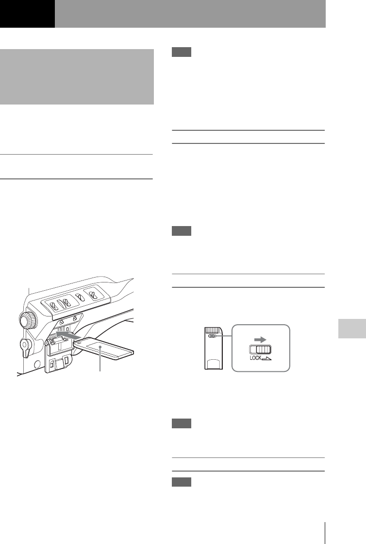
Handling the “Memory Stick” 185
Chapter 7 Saving and Loading User Setting Data
The “Memory Stick” can be inserted to or
removed from the camcorder with the power
turned on or off.
”Memory Sticks” usable with this
camcorder
With this camcorder, you can use a Sony
“Memory Stick”, “Memory Stick Duo”,
“Memory Stick PRO” whose capacity does not
exceed 4 GB, and “Memory Stick PRO Duo”.
For details, see “About a “Memory Stick”” on page
234.
Inserting a “Memory Stick”
1Open the cover of the menu operating
section.
2Hold the “Memory Stick” with the
notch facing downward and the arrow
facing away from you, and insert the
“Memory Stick” into the “Memory
Stick” slot until it clicks into place. Then
close the cover.
Note
If it does not fit into the slot properly or if there is some
resistance when you insert it, the “Memory Stick” may
be turned around or upside down. Do not force the
“Memory Stick” into the slot. Confirm the direction of
the notch and arrow on the “Memory Stick” before
inserting the “Memory Stick” and then try inserting it
again.
To remove the “Memory Stick”
1Check that the access indicator is not lit,
then gently press in the “Memory
Stick” once and release.
The “Memory Stick” pops out.
2Pull the “Memory Stick” towards you
to withdraw it from the slot.
Note
Do not remove the “Memory Stick” while the access
indicator is lit. You may lose data, or damage the
“Memory Stick”.
To protect saved data
To prevent accidental erasure of important setup
data, slide the LOCK switch on the “Memory
Stick” right to the write protect position.
It is now impossible to write or delete data on the
“Memory Stick”. If you try to do so, the message
“MEMORY STICK LOCKED” appears and the
data cannot be overwritten or deleted.
Note
“Memory Stick Duo” and “Memory Stick PRO Duo” do
not have this function.
To format a “Memory Stick”
Note
Do not format the “Memory Stick” using a PC.
Chapter7
Saving and Loading User Setting Data
Handling the “Memory
Stick”
Label

Saving and Recalling User Files
186
Chapter 7 Saving and Loading User Setting Data
(How to select an item in the menu screen: Turn
the MENU knob to move b to the desired item.)
1Display the MEMORY STICK page of
the FILE menu, and press the MENU
knob.
For details on menu operations, see “Basic
menu operations” on page 163.
2Select M.S. FORMAT, and press the
MENU knob.
A confirmation screen appears.
3Select “YES” and press the MENU
knob.
The camcorder is equipped with a “Memory
Stick” slot, which enables you to save the settings
in the USER menu as a user file onto the
“Memory Stick”. You can load these files from
the “Memory Stick” for immediate recall of a
particular setting configuration.
In addition to user files, you can save scene files,
reference files, lens files and ALL files in a
“Memory Stick”.
When a menu is displayed, inserting a “Memory
Stick” displays the appropriate file-related menu
page automatically.
You can save USER menu settings held in the
camcorder as user files in the “Memory Stick”.
You can save up to 100 user files in the “Memory
Stick”.
Insert the “Memory Stick” then proceed as
follows.
(How to select an item in the menu screen: Turn
the MENU knob to move b to the desired item.)
1Display the USER FILE page of the
FILE menu, and press the MENU knob.
For details on menu operations, see “Basic
menu operations” on page 163.
To set a file ID for the data to be saved
Set the file ID before going to step 2.
For details on setting the file ID, see “To set the
file ID” on page 187.
Saving and Recalling
User Files
Saving user menu data to the
“Memory Stick”
TOP?F01 USER FILE
USER FILE LOAD : EXEC
USER FILE SAVE : EXEC
F.ID :
ssssssssssssssss
USER PRESET : EXEC
Saving and Recalling User Files 187
Chapter 7 Saving and Loading User Setting Data
2Select USER FILE SAVE, and press the
MENU knob.
The USER SAVE page appears.
Up to 20 pages, from P00 to P19, can be used
to save user files to the “Memory Stick”.
Each page can hold up to five files.
3Turn the MENU knob until the page
which contains the desired file number
appears, and press the MENU knob.
4Select the desired file number, and
press the MENU knob.
The message “SAVE OK? YES b NO”
appears.
If a file number is followed by “NEW FILE”,
this means that the file is empty. If data is
stored in the file, the file number is followed
by the file name.
5To carry out the save, select YES and
press the MENU knob.
To cancel, press the MENU knob leaving b
pointing to NO.
The access indicator lights. When the saving
is completed, the message “COMPLETE”
appears and the access indicator goes off.
If no “Memory Stick” has been inserted
The message “NO MEMORY STICK” will
appear. Insert a “Memory Stick” and carry
out the operation once again.
If you select a file number where data has
already been saved
The message “OVERWRITE OK? YES b
NO” appears.
• To stop overwriting, press the MENU knob
leaving b pointing to NO.
• To overwrite, select YES and press the
MENU knob.
You can select the information displayed on
each USER SAVE or USER LOAD page.
For details, see “To select the file information
items to be displayed” on page 188.
About the USER menu settings to be saved in the
“Memory Stick”
Settings for items on all pages of the USER menu
are saved in the “Memory Stick” as a user file.
If data cannot be saved
If one of the following error messages appears
during or after the save operation, then the data
was not saved.
To set the file ID
You can set an file ID before you save your data
as a user file. This will help you identify the user
file quickly. The file ID that has been set is saved
together with the data.
Note
Set the file ID before saving data in the “Memory Stick”.
Otherwise, the file ID is not saved with the other data.
(How to select an item in the menu screen: Turn
the MENU knob to move b to the desired item.)
1Display the USER FILE page of the
FILE menu.
For details on menu operations, see “Basic
menu operations” on page 163.
2Select F. ID, and press the MENU knob.
A character table appears.
Error message Cause Action
NO MEMORY
STICK
(flashing)
No “Memory
Stick” is
inserted.
Insert or
reinsert the
“Memory
Stick”.
MEMORY
STICK
LOCKED
The LOCK
switch on the
“Memory
Stick” is set to
the write
protect
position.
Set the LOCK
switch to the
write enable
position.
MEMORY
STICK ERROR
(flashing)
Circuit or
“Memory
Stick” fault.
Recheck and
consult a Sony
service
representative.
USER FILE LOAD : EXEC
USER FILE SAVE : EXEC
F.ID :?
x
i#$%&'()*+,-./012345678
9:;<=>?@ABCDEFGHIJKLMNOP
QRSTUVWXYZ[ ]abcdefghijk
lmnopqrstuvwxyz~
INS DEL RET ESC END
TOP F01 USER FILE

Saving and Recalling User Files
188
Chapter 7 Saving and Loading User Setting Data
3Follow steps 3 and 4 described in
“Setting the shot ID” on page 175 to
enter characters.
4When you have finished entering the
file ID, turn the MENU knob to move x
to END, and press the MENU knob.
The entered file ID is now displayed.
When you carry out a user file save operation (see
page 186), the set file ID is saved to the “Memory
Stick” together with the data.
To select the file information items to be
displayed
You can select the user file information items to
be displayed on the USER FILE SAVE page and
USER FILE LOAD page (P00 to P19), that are
the pages used to save and call up the data to and
from “Memory Stick”.
(How to select an item in the menu screen: Turn
the MENU knob to move b to the desired item.)
1Display a USER FILE LOAD page or
USER FILE SAVE page of the USER
FILE menu, and press the MENU knob.
For details on menu operations, see “Basic
menu operations” on page 163.
2Select DISPLAY MODE, and press the
MENU knob.
3Select the desired type of file
information, and press the MENU
knob.
Note
The data loaded from the “Memory Stick” overwrites the
data saved in the camcorder.
(How to select an item in the menu screen: Turn
the MENU knob to move b to the desired item.)
1Display the USER FILE page of the
FILE menu, and press the MENU knob.
For details on menu operations, see “Basic
menu operations” on page 163.
2Select USER FILE LOAD, and press
the MENU knob.
The USER LOAD page appears.
3Turn the MENU knob until the page
which contains the desired file number
appears, then press the MENU knob.
4Select the desired file number, and
press the MENU knob.
The message “LOAD OK? YES b NO”
appears.
5To carry out the load, select YES and
press the MENU knob.
To cancel, press the MENU knob leaving b
pointing to NO.
The access indicator lights.
When the load is completed, the message
“COMPLETE” appears and the access
indicator goes off.
If data cannot be loaded
If one of the following error messages appears
during or after the load operation, then the data
was not loaded.
USER FILE LOAD : EXEC
USER FILE SAVE : EXEC
F.ID : ID-001
USER PRESET : EXEC
TOP F01 USER FILE
File ID that has been set appears.
Display type Description
ALL File ID (10 characters) and
date (year/month/day)
F.ID File ID (16 characters)
DATE Date saved (year/month/day/
hours/minutes/seconds)
MODEL Information on the model
Loading saved data from a
“Memory Stick”

Saving and Loading Scene Files 189
Chapter 7 Saving and Loading User Setting Data
(How to select an item in the menu screen: Turn
the MENU knob to move b to the desired item.)
1Display the USER FILE page of the
FILE menu, and press the MENU knob.
For details on menu operations, see “Basic
menu operations” on page 163.
2Select USER PRESET, and press the
MENU knob.
You can save various settings for shooting a
particular scene as a scene file. By loading the
scene file, you can quickly recreate setup
conditions suitable for the scene. You can save up
to five scene files in the camcorder memory and
up to 100 scene files in a “Memory Stick” .
You can also load data from the “Memory Stick”
into the camcorder memory.
Data that can be saved in a scene file
You can save the following data in a scene file:
• Values adjusted using the PAINT menu
• Shutter speed settings made in the standard
mode and ECS mode
• The white balance data included in a scene file
depends on the SCENE WHITE DATA setting
on the REFERENCE page of the FILE menu.
To save a scene file to the “Memory Stick”, insert
the “Memory Stick” into the “Memory Stick” slot
before starting the following operation.
(How to select an item in the menu screen: Turn
the MENU knob to move b to the desired item.)
1Display the SCENE FILE page of the
FILE menu, and press the MENU knob.
For details on menu operation, see “Basic menu
operations” on page 163.
To set a file ID for the data to be saved
Set the file ID before going to step 2.
For details on setting the file ID, see “To set the
file ID” on page 187.
Error
message
Cause Action
NO
MEMORY
STICK
(flashing)
No “Memory
Stick” is
inserted.
Insert or reinsert
the “Memory
Stick”.
MEMORY
STICK
ERROR
(flashing)
Circuit or
“Memory Stick”
fault.
Recheck, and
consult a Sony
service
representative.
FILE
ERROR
(flashing)
The “Memory
Stick” contains
data that cannot
be loaded into
this camcorder.
Data saved to a
“Memory Stick”
using a
camcorder
whose model is
not the same as
this camcorder
cannot be loaded
into this
camcorder.
Returning the user file settings to
the standard settings
Saving and Loading
Scene Files
Saving a scene file
s
1 :STANDARD
s
2 :STANDARD
s
3 :STANDARD
s
4 :STANDARD
s
5 :STANDARD
s
STANDARD
SCENE RECALL : EXEC
SCENE STORE : EXEC
F.ID: STANDARD
TOP?F04 SCENE FILE

Saving and Loading Scene Files
190
Chapter 7 Saving and Loading User Setting Data
2Select SCENE STORE, and press the
MENU knob.
The SCENE STORE page appears.
3Press the MENU knob, then select the
desired file number, and press the
MENU knob again.
The file to be saved is selected.
When no “Memory Stick” is inserted
Select the desired memory number, and press
the MENU knob.
When the save is completed, the SCENE
FILE page appears again.
When you select a file number where data
has already been saved
The message “OVERWRITE OK? YES b
NO” appears.
• To cancel the overwriting, press the MENU
knob leaving b pointing to NO.
• To overwrite, select YES and press the
MENU knob.
When a “Memory Stick” is inserted
You can use up to 20 pages, from P01 to P20,
to save scene files in the “Memory Stick”.
Each page can hold up to five files.
1Turn the MENU knob until the page
which contains the desired file number
appears, then press the MENU knob.
2Select the desired file number, and
press the MENU knob.
The message “STORE OK? YES b
NO” appears.
3To carry out the save, select YES and
press the MENU knob.
To cancel, press the MENU knob
leaving b pointing to NO.
You can select the file information items
to be displayed on each page of SCENE
STORE and SCENE RECALL.
For details, see “To select the file information
items to be displayed” on page 188.
To save scene files stored in the
camcorder memory to the “Memory
Stick”
The five scene files stored in the camcorder
memory can be saved to the “Memory Stick” all
in a single operation.
(How to select an item in the menu screen: Turn
the MENU knob to move b to the desired item.)
1Display the SCENE FILE page of the
FILE menu, and press the MENU knob.
For details on menu operations, see “Basic
menu operations” on page 163.
2Select SCENE STORE, and press the
MENU knob.
One of the SCENE STORE pages appears.
3Turn the MENU knob to select the
desired SCENE STORE page, and
press the MENU knob.
4Select 5FILE SAVE B MEM1-5, and
press the MENU knob.
The message “STORE OK? YES b
NO”appears.
5To carry out the save, select YES and
press the MENU knob.
To cancel, press the MENU knob leaving b
pointing to NO.
When the save is completed, the message
“COMPLETE” appears.
Note
If files have been saved in the page selected in step 3,
those files are replaced with files loaded from the
camcorder memory. For example, files from 001 to 005
are replaced by the above procedure.
To set the file ID
You can set an file ID before you save your data
as a scene file. This will help you identify the
scene file quickly. The file ID that has been set is
saved together with the data.
You can carry out a scene file ID setting operation
on the SCENE FILE page of the FILE menu.
For details about this operation, see the description
of step 2 and following of “To set the file ID” on
page 187.

Saving and Loading Scene Files 191
Chapter 7 Saving and Loading User Setting Data
To select the file information items to be
displayed
You can select the items of file information to be
displayed on the SCENE STORE pages (P01 to
P20) or the SCENE RECALL pages (P01 to P20)
used for saving data to or loading data from a
“Memory Stick”.
You can select the scene file information items to
be displayed on the SCENE STORE page and
SCENE RECALL page of the SCENE FILE
menu.
For details about item selection, see the description
of step 2 and following of “To select the file
information items to be displayed” on page 188.
(How to select an item in the menu screen: Turn
the MENU knob to move b to the desired item.)
1Display the SCENE FILE page of the
FILE menu, and press the MENU knob.
For details on menu operations, see “Basic
menu operations” on page 163.
2To load the scene file stored in the
camcorder, select the desired file
number, and press the MENU knob.
s on the left of the file number changes to
x. The camcorder is set up according to the
loaded scene file.
To cancel the selected scene file
Turn the MENU knob to move b to x, and
press the MENU knob again. x changes to
s. The camcorder returns to the settings
before selecting this scene file.
To load a scene file saved in the “Memory
Stick”
1Select SCENE RECALL, and press the
MENU knob.
The SCENE RECALL page appears.
2Turn the MENU knob until the page
which contains the desired file number
appears, then press the MENU knob.
3Select the desired file number, and
press the MENU knob.
The message “RECALL OK? YES b
NO” appears.
3To carry out the recall, select YES and
press the MENU knob.
To cancel, press the MENU knob leaving b
pointing to NO.
When the loading is completed, the message
“COMPLETE” appears. The camcorder is
set up according to the loaded scene file. If no
file is present with a particular file number,
this is shown as “NO FILE”.
To load scene files from the “Memory
Stick” into the camcorder memory
You can load up to five scene files stored in the
“Memory Stick” into the camcorder memory all
in a single operation.
(How to select an item in the menu screen: Turn
the MENU knob to move b to the desired item.)
1Display the SCENE FILE page of the
FILE menu, and press the MENU knob.
For details on menu operations, see “Basic
menu operations” on page 163.
2Select SCENE RECALL, and press the
MENU knob.
The SCENE RECALL page appears.
3Turn the MENU knob until the SCENE
RECALL page which contains the
desired scene files appears, and press
the MENU knob.
4Select 5FILE LOAD b MEM1-5, and
press the MENU knob.
The message “RECALL OK? YES b NO”
appears.
Loading scene files
s
1 :SCENE 25
x
2 :SCENE 26
s
3 :SCENE 27
s
4 :SCENE 28
s
5 :NO FILE
s
STANDARD
SCENE RECALL : EXEC
SCENE STORE : EXEC
F.ID :SCENE21
TOP F04 SCENE FILE

Jumping to a File-Related Menu Page When Inserting a “Memory Stick”
192
Chapter 7 Saving and Loading User Setting Data
5To carry out the load (recall), select
YES and press the MENU knob.
To cancel, press the MENU knob leaving b
pointing to NO.
When loading is complete, the message
“COMPLETE” appears and the access
indicator goes off.
Notes
• The scene files loaded from the “Memory Stick”
overwrite data saved in the camcorder memory.
• To load the scene file saved in the camcorder
memory when the “Memory Stick” is inserted,
return to the P00 SCENE RECALL page and load
the desired scene file in the camcorder memory.
• When there is no file to be loaded (shown as “NO
FILE”), an existing file of the same number is
unaffected. In the example shown in step 4,
MEM3 is not overwritten.
(How to select an item in the menu screen: Turn
the MENU knob to move b to the desired item.)
1Display the SCENE FILE page of the
FILE menu, and press the MENU knob.
For details on menu operations, see “Basic
menu operations” on page 163.
2Select STANDARD, and press the
MENU knob.
s displayed on the left of STANDARD
changes to x. When x changes to s once
again, the settings of the camcorder are reset
to the standard settings.
If you press the MENU knob again while x
is displayed, the operation is cancelled and
the camcorder returns to the settings before
STANDARD was selected.
A “Memory Stick” enables you to save user files,
scene files, lens files, reference files and ALL
files.
The camcorder menu system allows you to make
a setting so that when a “Memory Stick” holding
these files is inserted while in menu operating
mode, a menu page relating to the desired file is
automatically displayed on the screen. Thus you
can proceed to file operation quickly. This is very
convenient especially when you manage data files
using “Memory Stick”s.
(How to select an item in the menu screen: Turn
the MENU knob to move b to the desired item.)
1Display the MEMORY STICK page of
the FILE menu, and press the MENU
knob.
For details on menu operations, see “Basic
menu operations” on page 163.
2Select MS IN > JUMP TO, and press the
MENU knob.
The MS IN > JUMP TO page allows you to
select one of the following settings.
3Turn the MENU knob until the name of
the desired file page appears, then press
the MENU knob.
Notes
In the following cases, jumping to the target page is
impossible.
• When the power is turned on after you insert a
“Memory Stick”.
• When OFF is selected on the MS IN > JUMP TO page.
Returning the scene file settings
to the standard settings
DISPLAY MODE : ALL
001.SCENE1
002.SCENE2
003.NO FILE
004.SCENE4
005.SCENE5
***.5FILE LOAD MEM1-5
ESC P01 SCENE RECALL
RECALL OK? YES NO
Jumping to a File-Related
Menu Page When Inserting
a “Memory Stick”
Setting Description
OFF Disables this function. Menu pages
do not change when a “Memory
Stick” is inserted.
USER Jumps to the USER FILE page.
ALL Jumps to the ALL FILE page.
SCENE Jumps to the SCENE FILE page.
LENS Jumps to the LENS FILE 1 page.
REFER Jumps to the REFERENCE page.
USER 1 Jumps to the USER 1 FILE page.

Jumping to a File-Related Menu Page When Inserting a “Memory Stick” 193
Chapter 7 Saving and Loading User Setting Data
• When any of the following menu pages is already
displayed.
- A file-related page such as the USER FILE page of
the FILE menu
- MEMORY STICK, ALL FILE, SCENE FILE,
LENS FILE, REFERENCE or ROM VERSION
page
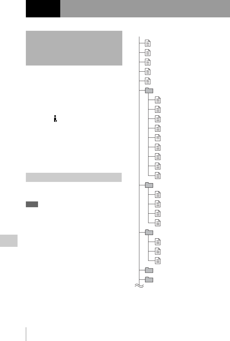
Overview
194
Chapter 8 File Operations
A remote computer can be connected to this unit
and used to operate on recorded data which has
been saved in data files, such as video and audio
data files.
There are two ways to connect a remote
computer.
• FAM connection
Connect the (i.LINK) S400 connector on this
unit to the i.LINK (IEEE1394) connector on the
remote computer, using an i.LINK cable (see
page 199).
• FTP connection
Connect the network connectors on this unit and
the remote computer, using a network cable (see
page 203).
The following figure shows the directory
structure of discs visible to a remote computer.
Note
This structure is not the same as the actual structure
recorded on the disc.
a) Root directory
b) Only when NAMING FORM on the FILE NAMING
page of the OPERATION menu is set to FREE
Chapter8File Operations
Overview
Directory structure
root a)
INDEX.XML
ALIAS.XML b)
Clip
Edit
Sub
UserData
General
DISCMETA.XML
MEDIAPRO.XML
SYSPRO.XML
C0001.MXF
C0001M01.XML
C0002M02.KLV
C0003.MXF
C0003M01.XML
C0003M02.KLV
C0001M02.KLV
C0002.MXF
C0002M01.XML
E0001E01.SMI
E0001M01.XML
E0002E01.SMI
E0002M01.XML
C0001S01.MXF
C0002S01.MXF
C0003S01.MXF
(Continued)
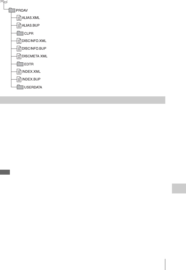
Overview 195
Chapter 8 File Operations
This section explains which operations are
possible on files stored in each directory.
When required, the following operation tables
distinguish reading and writing from partial
reading and writing.
Read: Read data sequentially from the start to the
end of the file.
Partial read: Read only a part of the data in the
file.
Write: Write data sequentially from the start to
the end of the file.
Partial write: Write data to a part of the file only.
Note
Operations other than Read and Partial read are possible
only when the Write Inhibit tab of the disc is set to
recording enabled.
(Continued)
File operation restrictions

Overview
196
Chapter 8 File Operations
Root directory
a) Only when NAMING FORM on the FILE NAMING
page of the OPERATION menu is set to FREE.
b) Only files which can be written by XDCAM.
Notes
• Directories cannot be created in the root directory.
• The directories in the root directory (Clip, Edit, Sub,
UserData, General, and PROAV) cannot be deleted or
renamed.
Clip directory
a) The “C*” part can be changed to a user-defined name.
b) Overwriting is not possible.
c) Only files which are 2 seconds or longer in length, in
a format matching the format (system frequency
(59.94i, 50i, or 25P)) and recording format (MPEG
HD422 and number of audio channels) of the recorded
sections of the disc, and which can be overwritten by
XDCAM.
d) Any clip may be selected and deleted.
e) Only files which can be written by XDCAM.
f) When the “C*” part of a C*.MXF file name is
changed, a C*M01.XML file (or a C*M02.KLV file)
with the same name in the “C*” part is also changed
automatically.
g) When a C*.MXF file is created, a C*M01.XML file
with the same name in the “C*” part is created
automatically.
File name Content Operations
Read/
Partial
read
Write/
Partial
write
Rename Create Delete
INDEX.XML Contains data for management of the
material on the disc.
Yes No No No No
ALIAS.XML a) Contains conversion tables for assigning
user-defined names to clips and clip lists.
Yes No No No No
DISCMETA.XML Contains metadata to indicate the disc
properties.
Yes Ye s b) No No No
MEDIAPRO.XML Contains a list of materials on the disc,
basic properties, related information, and
information about access methods.
Yes No No No No
SYSPRO.XML Contains system setting information and
menu setting information for the devices.
Yes No No No No
Other files Files other than the above - No - No -
File name Content Operations
Read/
Partial
read
Write/
Partial
write
Rename Create Delete
C*.MXF a) Clip file created by recording (MXF file)
*: 0001 to 9999
Yes No b), c) Ye s Ye s c) Yes d)
C*M01.XML a) Metadata file generated automatically
when C*.MXF file is created.
*: 0001 to 9999
Yes Ye s e) No f) No g) No h)
C*M02.KLV a) User metadata file. This type of file is
generated automatically during recording
via an FTP or FAM connection when the
unit recognizes that an MXF file contains
metadata that was generated by a non-
XDCAM device.
*: 0001 to 9999
Yes Ye s e) No f) Ye s e) Yes h)
Other files Files other than the above - No - No -

Overview 197
Chapter 8 File Operations
h) When a C*.MXF file is deleted, the C*M01.XML file
(or a C*M02.KLV file) with the same name in the
“C*” part is also deleted automatically.
Note
Directories cannot be created in the Clip directory.
Edit directory
a) The “E*” part can be changed to a user-defined name.
b) Only files which can be written by XDCAM. Partial
writing is not possible.
c) Only files which can be written by XDCAM.
d) When the “E*” part of a E*E01.SMI is changed, an
E*M01.XML file with the same name in the “E*” part
is also changed automatically.
e) When an E*E01.SMI file is created, an E*M01.XML
file with the same name in the “E*” part is also
generated automatically.
f) When an E*E01.SMI file is deleted, an E*M01.XML
file with the same name in the “E*” part is also deleted
automatically.
Note
Directories cannot be created in the Edit directory.
Sub directory
a) The “C*” part can be changed to a user-defined name.
b) When the “C*” part of a C*.MXF file name is
changed, a C*S01.MXF file with the same name in the
“C*” part is generated automatically.
c) When a C*.MXF file is created, a C*S01.MXF file
with the same name in the “C*” part is generated
automatically.
d) When a C*.MXF file is deleted, the C*S01.MXF file
with the same name in the “C*” part is also deleted
automatically.
Note
Directories cannot be created in the Sub directory.
File name Content Operations
Read/
Partial
read
Write/
Partial
write
Rename Create Delete
E*E01.SMI a) Clip list file
*: 0001 to 0099
Yes Ye s b) Yes Ye s c) Yes
E*M01.XML a) Metadata file generated automatically
when E*E01.SMI file is created.
*: 0001 to 0099
Yes Ye s b) No d) No e) No f)
Other files Files other than the above - No - No -
File name Content Operations
Read/
Partial
read
Write/
Partial
write
Rename Create Delete
C*S01.MXF a) Proxy AV data (MXF file) generated
automatically when a C*.MXF file is
created.
*: 0001 to 9999
Yes No No b) No c) No d)
Other files Files other than the above - No - No -

Overview
198
Chapter 8 File Operations
UserData directory
a) UTF-8 file names can be up to 63 bytes in length.
(Depending on the character type, file names
(including extension) may be limited to 21
characters.)
The following directory operations are possible in the
UserData directory.
• Directory creation (up to 62 levels, including the
UserData directory)
• Deletion and renaming of directories
General directory
a) UTF-8 file names can be up to 63 bytes in length.
(Depending on the character type, file names
(including extension) may be limited to 21
characters.)
The following directory operations are possible in the
General directory.
• Directory creation (up to 63 levels, including the
General directory)
• Deletion and renaming of directories
Notes
• The maximum number of files that can be created on
one disc, including directories, is 5000 for a single-
layer disc and 6000 for a dual-layer disc.
• File names and directory names can use letters,
numbers, and symbols from the Unicode 2.0 (UTF-8)
character set. 1)
However, the following control characters and
symbols cannot be used.
- Control characters: U+0000 to U+001F, U+007F
- Symbols: ", *, /, :, <, >, ', ?, \, |
• To create a new directory in the General directory, first
create a directory on the desktop and rename it using
only characters that can be used on this unit. Then drag
it from the desktop and drop it in the General directory.
1) The following character codes cannot be used by FAM
connections.
U+010000, U+020000, U+030000, U+040000,
U+050000, U+060000, U+070000, U+080000,
U+090000, U+0A0000, U+0B0000, U+0C0000,
U+0D0000, U+0E0000, U+0F0000, U+100000
PROAV directory
This directory displays individual files on the
disc.
To enable display of the PROAV directory, set
PROAV DISPLAY on the CAM CONIG 1 page
of the MAINTENANCE menu to “ENABL”.
File name Content Operations
Read/
Partial
read
Write/
Partial
write
Rename Create Delete
Any file Yes Yes Yes a) Ye s Yes
File name Content Operations
Read/
Partial
read
Write/
Partial
write
Rename Create Delete
Any file Yes Yes Yes a) Ye s Yes

File Operations in File Access Mode (for Windows) 199
Chapter 8 File Operations
File access mode operating environment
Operating system requirements for file operations
by file access mode (called FAM below) are as
follows.
Computer operating system: Microsoft
Windows XP Professional SP2 or higher, or
Microsoft Windows Vista Business/Ultimate
(32 bit)
Note
64-bit editions of Windows Vista are not supported.
Preparations
Install the FAM driver on the remote computer.
To install the FAM driver
Insert the supplied CD-ROM (XDCAM
Application Software) into the CD-ROM drive of
your computer, navigate to the FAM Driver
directory, and run the installer in the directory for
your operating system, then follow the
installation instructions.
For details, refer to the ReadMe file contained on the
CD-ROM disc.
Note
Use Version 2.10 or higher of the FAM driver. The FAM
driver on the supplied CD-ROM is Version 2.10 or
higher.
If a FAM driver is already installed on your computer,
check the version (see the next section).
To check the FAM driver version
For Windows XP:
Select Control Panel > Add or Remove Programs
> ProDisc, and click on “Click here for support
information.”
For Windows Vista:
(1) Select Control Panel > Programs, open the
Programs and Features window, right click in the
window’s header bar (including the Name,
Publisher, and other headers), and select Others...
(2) In the Choose Details dialog, check the
Version check box and click OK. The Version
column is displayed, allowing you to check the
version of ProDisc.
To enable FAM connections over the i.LINK
connector
(How to select an item in the menu screen: Turn
the MENU knob to move b to the desired item.)
1Turn the MENU knob to scroll to the
POWER SAVE page of the
OPERATION menu, then press the
MENU knob.
For details on menu operations, see “Basic
menu operations” on page 163.
2Move b to i.LINK(FAM) then press the
MENU knob.
3Turn the MENU knob to select
“ENABL”, then press the MENU knob.
The message “Valid after power off.”
appears.
4Power the camcorder off, and then
power it on again.
The setting made in step 3 is enabled.
1If there is a disc loaded in this unit, put
the unit into the following state.
Recording, playback, search and other
disc operations: Stopped
THUMBNAIL indicator: Off
Disc access by clip deletion, disc
formatting, or other operation:
Stopped
Picture Cache function and Interval Rec
function: Off
MENU ON/OFF switch: OFF
Unsaved current clip list: Save or clear
File Operations in File
Access Mode (for
Windows)
Making FAM connections
U07 POWER SAVE
ETHERNET/USB : DSABL
iLINK(FAM) : DSABL
REC AUDIO OUT : EE
TOP
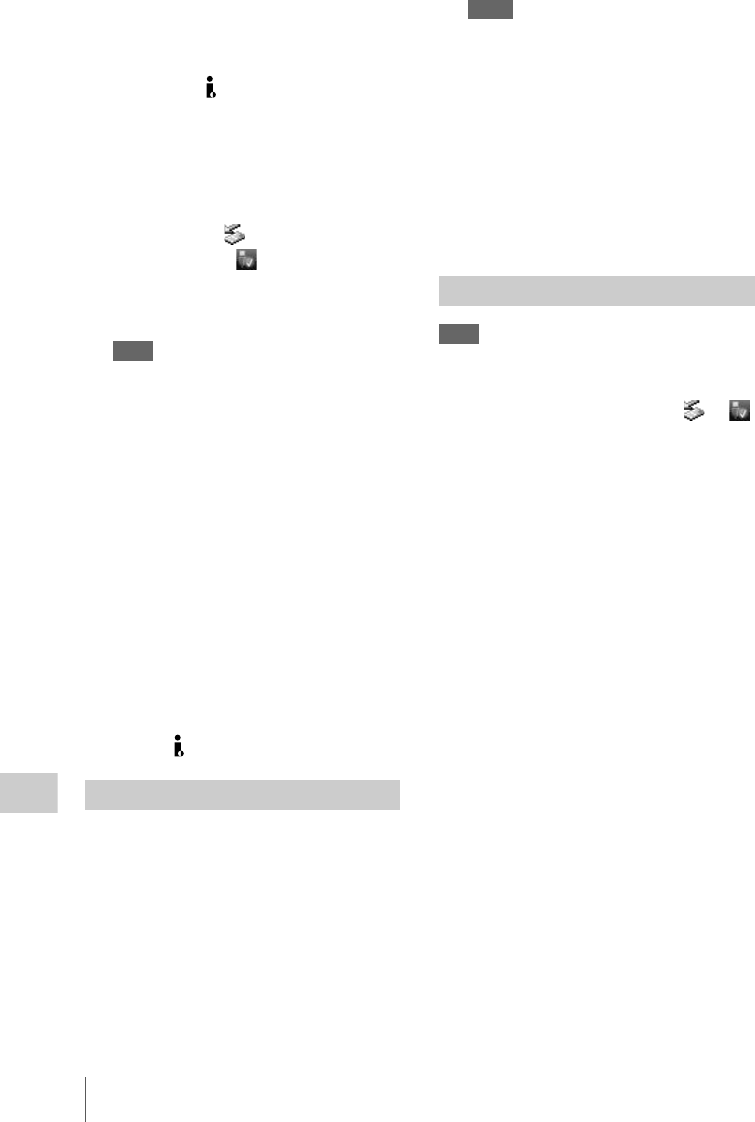
File Operations in File Access Mode (for Windows)
200
Chapter 8 File Operations
2If this unit is connected to a remote
computer by FTP, log out from the FTP
session (see page 204).
3Connect the (i.LINK) S400 connector
on this unit to the i.LINK (IEEE1394)
connector on the remote computer,
using an i.LINK cable.
Windows recognizes this unit as a removable
disc, and displays one of the following icons
on the remote computer’s taskbar:
•Windows XP:
•Windows Vista:
The remote computer is now able to perform
file operations when a disc is inserted into
this unit.
Note
You will not be able to log in if you put the unit into
the state described in step 1 after connecting the
cable. To log in, disconnect the cable, put the unit
into the state described in step 1, and connect it
again.
When you make your first FAM connection
The Found New Hardware Wizard dialog appears
when you connect this unit to your computer.
Select “Install the software automatically
(Recommended)”, and then click the Next button.
Click the Finish button when the software
installation finishes.
Operation limitations during FAM connections
• With the exception of the EJECT button,
recording buttons and playback control buttons
are disabled.
• VDR of this unit cannot be controlled from
devices connected to the REMOTE connector
(8-pin) and (i.LINK) S400 connector.
1Start Explorer.
Check that a drive letter has been assigned to
this unit. (The drive letter will differ
depending on the number of other peripherals
connected to the remote computer.)
2Use Explorer to perform file operations
on the disc loaded in this unit.
You can operate in the same way that you
operate on local drives and files on network
computers.
Notes
• If you power this unit off during a FAM
connection, the data transferred thus far is
discarded.
• All file operations are not possible for some types
of files.
For details, see “File operation restrictions”
(page 195).
To eject discs from a remote computer
Right click the icon representing this unit in
Explorer, and select Eject from the menu which
appears.
Note
Do not disconnect the cable before performing steps 1 to
3.
1Do one of the following on the or
icon displayed in the remote computer’s
taskbar.
• Double click.
• Right click to display the context menu and
select “Safely Remove Hardware” from the
context menu.
The Safely Remove Hardware dialog
appears.
2Select “Sony XDCAM PDW-700 IEEE
1394 SBP2 Device” and click “Stop”.
The Stop a Hardware device dialog appears.
3Select “Sony XDCAM PDW-700 IEEE
1394 SBP2 Device” and click “OK”.
In Windows XP, “Sony XDCAM PDW-700
IEEE 1394 SBP2 Device” is deleted from the
list of hardware devices.
In Windows Vista, the message “This device
can be safely removed from your computer.”
appears.
This unit can now resume normal operations.
(The limitations described in “Operation
limitations during FAM connections” on
page 200 no longer apply.)
4Disconnect the i.LINK cable as
required.
Operating on files
Exiting file operations

File Operations in File Access Mode (for Macintosh) 201
Chapter 8 File Operations
To make a reconnection
To reconnect after exiting file operations, do one
of the following, depending on whether an
i.LINK cable is connected.
i.LINK cable is not connected: Connect this unit
and a remote computer with an i.LINK cable.
i.LINK cable is connected: Disconnect the
i.LINK cable from either this unit or the
remote computer, wait for at least 10
seconds, and then reconnect the disconnected
cable.
The unit is powered off and an i.LINK cable is
connected: Power the unit on.
File access mode operating environment
Operating system requirements for file operations
by file access mode are as follows.
Computer operating system: Mac OS X
v10.4.11 or higher
Preparations
Do the following on the remote computer and this
unit.
• Install the FAM driver on the remote computer
(see the next item).
• Set i.LINK(FAM) on the POWER SAVE page
of the OPERATION menu to ENABL (see
page 181).
To install the FAM driver
Insert the supplied CD-ROM (XDCAM
Application Software) into the CD-ROM drive of
your computer, and execute the FAM Driver
>Mac >dmg file of the FAM Driver, then follow
the installation instructions.
For details, refer to the ReadMe file contained on the
CD-ROM disc.
To check the FAM driver version
Connect this unit to your computer with an
i.LINK cable, and then, with a disc loaded, start
the system profiler utility of the application. The
version appears to the right of “prodisk_fs” when
you select “Advanced Functions” under
“Software”.
1If there is a disc loaded in this unit, put
the unit into the following state.
Recording, playback, search and other
disc operations: Stopped
THUMBNAIL indicator: Off
Disc access by clip deletion, disc
formatting, or other operation:
Stopped
Picture Cache function and Interval Rec
function: Off
File Operations in File
Access Mode (for
Macintosh)
Making FAM connections
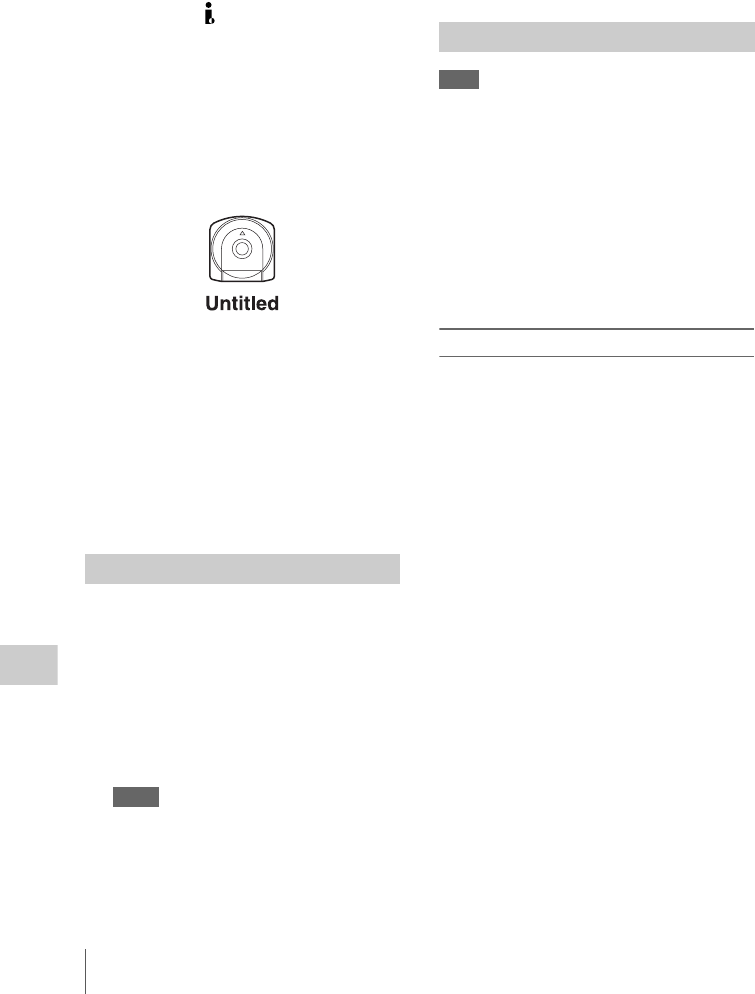
File Operations in File Access Mode (for Macintosh)
202
Chapter 8 File Operations
MENU ON/OFF switch: OFF
Unsaved current clip list: Save or clear
2If this unit is connected to a remote
computer by FTP, log out from the FTP
session (see page 204).
3Connect the (i.LINK) S400 connector
on this unit to the i.LINK (IEEE1394)
connector on the remote computer,
using an i.LINK cable.
When a disc is inserted into this unit, the
remote computer recognizes this unit as a
removable disc. The following icon appears
in the Finder on the remote computer,
indicating that the computer is now able to
perform file operations.
Operation limitations during FAM connections
• With the exception of the EJECT button,
recording buttons and playback control buttons
are disabled.
• Do not use the EJECT button to eject discs.
Always eject discs from the computer.
• Do not disconnect the i.LINK cable during a
FAM connection. Doing so may result in
unstable operation. Always eject any loaded
disc before disconnecting the i.LINK cable.
1Start the Finder.
Check to be sure that a drive has been
assigned to this unit.
2Operate from the Finder on the files on
the disc in this unit.
You can operate in the same way that you
operate on local drives and files on network
computers.
Notes
• If you power this unit off during a FAM
connection, the data transferred thus far is
discarded.
• All file operations are not possible for some types
of files.
For details, see “File operation restrictions”
(page 195).
To eject discs from a remote computer
Click the eject button to the right of the icon for
this unit in the Finder, or drag the icon for this unit
from the Finder to the Trash.
Note
Do not disconnect the cable before performing steps 1
and 2.
1Eject the disc by clicking the eject
button to the right of the icon for this
unit in the Finder, or by dragging the
icon for this unit from the Finder to the
Trash.
2Disconnect the i.LINK cable as
required.
To make a reconnection
To reconnect after exiting file operations, do one
of the following, depending on whether an
i.LINK cable is connected.
i.LINK cable is not connected: Connect this unit
and a remote computer with an i.LINK cable.
i.LINK cable is connected: The unit is mounted
automatically, so you do not need to do
anything.
The unit is powered off and an i.LINK cable is
connected: Power the unit on.
Operating on files
Exiting file operations

FTP File Operations 203
Chapter 8 File Operations
File operations between this unit and a remote
computer can be carried out by the File Transfer
Protocol (called FTP below).
Preparations
1Connect the network connectors of this
unit and a remote computer with a
network cable. Or connect this unit to
the network to which the remote
computer is connected.
2On the NETWORK page of the
MAINTENANCE menu, set the IP
address and other network setting items
for this unit. 1)
For details on menu operations, see “Basic
menu operations” on page 163.
If network settings have already been
made
Check the IP address of this unit.
1) This unit is able to acquire an IP address
automatically from a DHCP server. It also
supports an Auto-IP function to assign an IP
address automatically when access from this unit
to the DHCP server times out. You can check
DHCP settings and the assigned IP address on the
NETWORK page of the MAINTENANCE
menu.
Note
If this unit is directly connected to a computer
running Windows Vista with a network cable,
change the setting as follows:
(1)Open “Network and Sharing Center” >“Manage
network connections” >“Local Area Connection”
in the control panel. (2) In the “Local Area
Connection Properties”, uncheck the “Internet
Protocol Version 6 (TCP/IPv6)”, and then click the
OK button.
3Turn the MENU knob to scroll to the
POWER SAVE page of the
OPERATION menu, then press the
MENU knob.
4Move b to ETHERNET/USB then press
the MENU knob.
5Turn the MENU knob to select
“ENABL”, then press the MENU knob.
FTP connections between this unit and a remote
computer can be made with either of the
following.
• The command prompt
• FTP client software
This section explains how to use the command
prompt. For more information about using FTP
client software, refer to the documentation of the
FTP client software on your system.
To log in
If this unit is connected to a remote computer with
a FAM connection, first exit file operations on the
FAM connection (see page 200).
1Load a disc into this unit and put the
unit into the following state.
Recording, playback, serch, and other disc
operations: Stopped
THUMBNAIL indicator: Off
Disc access by clip deletion, disc
formatting, or other operation:
Stopped
Picture Cache function and Interval Rec
function: Off
MENU ON/OFF switch: OFF
Unsaved current clip list: Save or clear
Note
Login is not possible unless the unit is in the state
described above.
2Start the command prompt.
FTP File Operations
Making FTP connections
U07 POWER SAVE
ETHERNET/USB : DSABL
iLINK(FAM) : DSABL
REC AUDIO OUT : EE
TOP

FTP File Operations
204
Chapter 8 File Operations
3Enter “ftp <SP> <IP address>”, and
press the Enter key. (<SP> refers to a
space.)
For example, if the IP address of this unit is
set to 192.168.001.010, enter “ftp
192.168.1.10”.
Refer to the Windows help for more information
about the FTP command.
If the connection succeeds, you are prompted
to enter a user name.
4Enter the user name “admin” and press
the Enter key.
When the user name is verified, your are
prompted to enter a password.
5Enter the password and press the Enter
key.
The password is set to “pdw-700” when the
unit is shipped from the factory.
The login is complete when the password is
verified.
See “Command list” (page 204) for the protocol
supported by this unit.
If the connection times out
This unit terminates FTP connections if no
command is received within 90 seconds of
the last command. If this occurs, log out (see
the next section) and repeat steps 2 to 4.
Note
If you power this unit off during an FTP connection,
the data transferred thus far is discarded.
To log out
To log out after finishing file operations, enter
“QUIT” at the command prompt and press the
Enter key.
This unit supports standard protocol (see the next
section), and extended protocol (see page 207).
Notes
• To execute FTP commands, you must install
application software such as PDZ-1 on your computer.
• The commands supported by application software
vary.
• An FTP client that supports UTF-8 is required to use
Unicode characters other than ASCII characters.
Command prompt FTP commands do not support
UTF-8.
Standard commands
In the command syntax column, <SP> means a
space, entered by pressing the space bar, and
<CRLF> means a new line, entered by pressing
the Enter key.
USER
Send this command to begin the login process.
Syntax: USER <SP> <username> <CRLF>
Input example: USER admin
PASS
After sending the USER command, send this command
to complete the login process.
Syntax: PASS <SP> <password> <CRLF>
Input example: PASS pdw-700
QUIT
Terminates the FTP connection. If a file is being
transferred, terminates after completion of the
transfer.
Syntax: QUIT <CRLF>
PORT
Specifies the IP address and port to which this unit
should connect for the next file transfer (for data transfer
from this unit).
Syntax: PORT <SP> <h1,h2,h3,h4,p1,p2>
<CRLF>
h1 (most significant byte) to h4 (least
significant byte): IP address
p1 (most significant byte), p2 (least
significant byte): Port address
Input example: PORT 10,0,0,1,242,48
(IP address: 10.0.0.1, Port number: 62000)
PASV
This command requests this unit to “Listen” on a data
port (which is not its default data port). It puts this unit
into passive mode, waiting for the remote computer to
make a data connection.
Syntax: PASV <CRLF>
TYPE
Specifies the type of data to be transferred.
Syntax: TYPE <SP> <type-code (options
delimited by <SP>)> <CRLF>
Command list

FTP File Operations 205
Chapter 8 File Operations
<type-code> can be any of the following. However,
for XDCAM, data is always transferred as “I”,
regardless of the type-code specification.
•A: ASCII
- N: Non-print
- T: Telnet format
- C: ASA Carriage Control
• E: EBCDIC
- N: Non-print
- T: Telnet format
- C: ASA Carriage Control
• I: IMAGE (Binary) (default)
• L: LOCAL BYTE
- SIZE: byte size
Input example: TYPE I
STRU
Specifies the data structure.
Syntax: STRU <SP> <structure-code> <CRLF>
<structure-code> can be any of the following.
However, for XDCAM, the structure is always “F”,
regardless of the structure-code specification.
• F: File structure (default)
• R: Record structure
• P: Page structure
Input example: STRU F
MODE
Specifies the transfer mode.
Syntax: MODE <SP> <mode-code> <CRLF>
<mode-code> can be any of the following.
However, for XDCAM, the mode is always “S”,
regardless of the mode-code specification.
• S: Stream mode (default)
• B: Block mode
• C: Compressed mode
Input example: MODE S
LIST
Sends a list of files from this unit to the remote computer.
Syntax: LIST <SP> <options> <SP> <path-name>
<CRLF>
<options> can be any of the following.
• -a: Also display file names that begin with “·”.
• -F: Append “/” to directory names.
The following data is transferred, depending on
whether <path-name> specifies a directory or file.
• Directory specified: A list of the files in the
specified directory
• File specified: Information about the specified
file
• No specification: A list of the files in the current
directory.
The wildcard characters “*” (any string) and “?”
(any character) may be used in <path-name>.
Input example 1: LIST -a Clip
Input example 2: LIST Clip/*.MXF
NLST
Sends a list of file names from this unit to the remote
computer, with no other information.
Syntax: NLST <SP> <options or path-name>
<CRLF>
The following options may be specified when no
path name is specified.
• -a: Also display file names that begin with “.”
• -I: Display information other than file name
(gives the same result as the LIST command).
• -F: Append “/” to directory names.
The following data is transferred, depending on
whether <path-name> specifies a directory or file.
• Directory specified: A list of the file names only
in the specified directory
• No specification: A list of the file names only in
the current directory.
The wildcard characters “*” (any string) and “?”
(any character) may be used in <path-name>.
Input example 1: NLST-I
Input example 2: NLST Clip/*.MXF
RETR
Begins transfer of a copy of a file in the specified path on
this unit to the current directory on the remote computer.
Syntax:RETR <SP> <path-name> <CRLF>
Input example: RETR Clip/C0001.MXF
STOR
Begins transfer of a copy of a file in the specified path on
the remote computer to the current directory on this unit.
Depending on the type of file transferred, the following
items are created.
•C*.MXF file
1), 3)
- C*M01.XML file (metadata)
- C*M02.KLV file (user metadata)
- C*S01.MXF file (proxy AV data)
- For C*.MXF files, the UMID of the copy source file
is not saved. However, it is saved if an immediately
preceding SITE UMMD extended command has
been issued.
• E*E01.SMI file 2), 3)
- E*M01.XML file (metadata)

FTP File Operations
206
Chapter 8 File Operations
1) *: 0001 to 9999
2) *: 0001 to 0099
3) The unit can handle files with user-defined names in
the “C*” and “E*”parts.
Notes
• For C*.MXF files, some data, such as file header
metadata, may be missing.
• Depending on the transfer destination directory and the
file type, transfer may not be possible.
• For C*.MXF files, the UMID of the copy source file is
not saved. However, it is saved if an immediately
preceding SITE UMMD extended command has been
issued.
For details, see “File operation restrictions” (page
195).
Syntax: STOR <SP> <path-name> <CRLF>
Input example: STOR Edit/E0001E01.SMI
RNFR
RNTO
Rename a file. Specify the file to be renamed with the
RNFR command, and specify the new name with the
RNTO command. (Always follow a RNFR command
with a RNTO command.)
Syntax: RNFR <SP> <path-name (before
change)> <CRLF>
RNTO <SP> <path-name (after change)>
<CRLF>
Input example: RNFR General/info.txt
RNTO General/clip_info.txt
DELE
Deletes the specified file on this unit.
Note
Depending on the directory and file type, deletion may
not be possible.
For details, see “File operation restrictions” (page
195).
Syntax: DELE <SP> <path-name> <CRLF>
Input example: DELE Clip/C0099.MXF
STAT
Sends information about properties of the specified file,
or about data transfer status, from this unit to the remote
computer.
The following property information is sent, depending
on the file type.
• MXF file
- File name
- File type
- CODEC type
- Frame rate
- Number of audio channels
- Duration
-UMID
• non-MXF file
-File name
Syntax: STAT <SP> <path-name> <CRLF>
The following data is transferred, depending on
whether a file is specified with <path-name>.
• File specified: The properties of the specified
file
• No specification: The size of the data transferred
thus far (unit: bytes)
Input example: STAT Clip/C0001.MXF
ABOR
Requests this unit to abort a file transfer currently in
progress.
Syntax: ABOR <CRLF>
SYST
Displays the system name of this unit.
Syntax: SYST <CRLF>
HELP
Displays a list of the commands supported by this unit,
or an explanation of the specified command.
Syntax: HELP <SP> <command-name> <CRLF>
The following data is transferred, depending on
whether a command name is specified with
<command-name>.
• Command name specified: Explanation of the
specified command.
• No specification: Command list
•Input example: HELP RETR
NOOP
Does nothing except return a response. (Used to check
whether this unit is running.)
Syntax: NOOP <CRLF>
PWD
Displays the current directory (“/” if the directory is the
root directory).
Syntax: PWD <CRLF>
CWD
Changes the current directory (moves from the current
directory to another directory).

FTP File Operations 207
Chapter 8 File Operations
Syntax: CWD <SP> <path-name> <CRLF>
Moves to a directory as follows, depending on
whether a directory is specified with <path-name>.
• Directory specified: To the specified directory
• No specification: To the root directory
Input example: CWD General
CDUP
Moves one level up in the directory structure (makes the
parent of the current directory be the current directory).
Syntax: CDUP <CRLF>
MKD
Creates a new directory.
Note
Directories can be created only in the General directory.
For details, see “File operation restrictions” (page
195).
Syntax: MKD <SP> <path-name> <CRLF>
RMD
Deletes a directory.
Note
Directories can be deleted only in the General directory.
For details, see “File operation restrictions” (page
195).
Syntax: RMD <SP> <path-name> <CRLF>
Extended commands
In the command syntax column, <SP> means a
space, entered by pressing the space bar, and
<CRLF> means a new line, entered by pressing
the Enter key.
SITE REPF
Sends an MXF file from the specified path on this unit to
the remote computer. This command allows you to
specify a segment in the body of the MXF file (composed
of video and audio data), for transfer of the required
segment only.
Notes
• A segment greater than the file size cannot be
specified.
• This command cannot be used when the path name
contains a space. Use the SITE REPFL command
instead.
Syntax: SITE REPF <SP> <path-name> <SP>
<start-frame> <SP> <transfer-size>
<CRLF>
<start-frame> specifies an offset from the start of
the file. Data is transferred from the video frame at
the offset (the first frame is 0).
<transfer-size> specifies the number of video
frames to transfer (specify 0 to transfer to the end of
the file).
Input example: SITE REPF Clip/C0001.MXF 5
150 (Transfer C0001.MXF. Body data is
transferred only from frame 6 to frame
150.)
SITE REPFL
Sends an MXF file from the specified path on this unit to
the remote computer. This command allows you to
specify a segment in the body of the MXF file (composed
of video and audio data), for transfer of the required
segment only.
Note
A segment greater than the file size cannot be specified.
Syntax: SITE REPFL <SP> “<path-name>” <SP>
<start-frame> <SP> <transfer-size>
<CRLF>
<path-name> specifies the path name of the file to
transfer. Enclose the path name in double quotation
marks.
<start-frame> specifies an offset from the start of
the file. Data is transferred from the video frame at
the offset (the first frame is 0).
<transfer-size> specifies the number of video
frames to transfer (specify 0 to transfer to the end of
the file).
Input example: SITE REPFL “Clip/sakura
0001.MXF 5” 150 (Transfer sakura
0001.MXF. Body data is transferred only
from frame 6 to frame 150.)
SITE FSTS
Acquires the system status of this unit.
One of the following status codes is sent.
0: Initial state, or no disc is loaded.
1: File system mount is OK.
3: File system mount is not OK.
Syntax: SITE FSTS <CRLF>
SITE MEID
Acquires the media ID of the disc loaded in this unit.

Recording Continuous Timecode With FAM and FTP Connections
208
Chapter 8 File Operations
Syntax: SITE MEID <CRLF>
SITE FUNC
Acquires the function and version of the expanded
commands.
Information is sent in the following format.
<main function> <SP> <branch function> <SP>
<branch function version>
For XDCAM, sent in a format like “200 MXF DISK 1”
(200 is a response code).
Syntax: SITE FUNC <CRLF>
SITE UMMD
When C*.MXF file is sent with the STOR, the copy
source UMID is saved if this command is invoked
immediately before the STOR command.
Syntax: SITE UMMD <CRLF>
SITE DF
Acquires the amount of free disc space.
Syntax: SITE <SP> DF <CRLF>
SITE CHMOD
Locks and unlocks clips. Also sets permissions for
directories and files in the General directory.
Syntax: SITE CHMOD <SP> <flag> <SP> <path-
name> <CRLF>
Specify one of the following values in <flag>,
according to the specification in <path-name>.
• When a clip is specified in <path-name>:
444: Lock.
666: Unlock.
• When a directory in the General directory is
specified in <path-name>:
555: Forbid writing to the directory.
777: Allow writing to the directory.
• When a file in the General directory is specified
in <path-name>:
444: Forbid writing to and execution of the file.
555: Forbid writing to the file, but allow
execution.
666: Allow writing to the file, but forbid
execution.
777: Allow writing to and execution of the file.
Input example: SITE CHMOD 444 Clip/
C0001.MXF (Lock clip C0001.MXF)
When you are connected to the unit by FAM or
FTP, you can create new clips with timecode that
is continuous with the timecode of the last frame
of the last clip on the disc. To record continuous
timecode, set PRESET/REGEN/CLOCK switch
to “REGEN”, and then proceed as follows.
FAM connection
Write clip files to the unit from the computer or
other device that is connected to this unit.
FTP connection
Use the “STOR” command to transfer clip files
from the computer that is connected to this unit. If
you issue the “SITE UMMD” command
immediately before the “STOR” command, the
original timecode of the transferred file is
recorded, regardless of the setting of PRESET/
REGEN/CLOCK switch.
Recording Continuous
Timecode With FAM and
FTP Connections
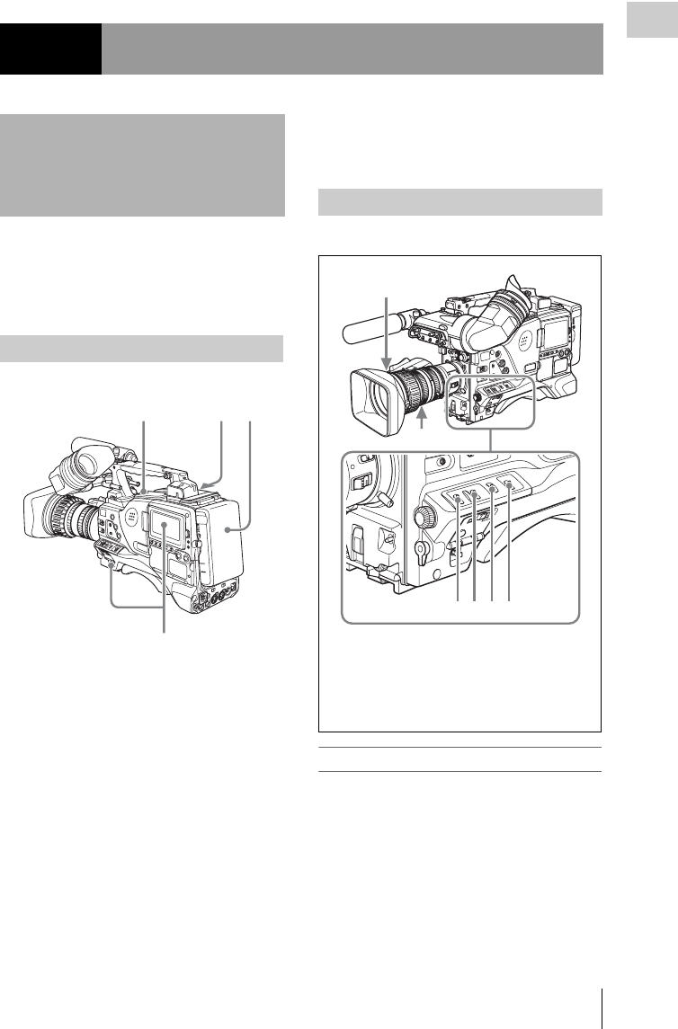
Testing the Camcorder Before Shooting 209
Chapter 9 Maintenance
Check the functions of the camcorder before
setting out for a shooting session, preferably by
operating the camcorder together with a color
video monitor.
1Attach a fully charged battery pack.
2Set the POWER switch to ON and
check that the HUMID indicator does
not appear and that the BATT indicator
shows at least five segments.
• If the HUMID indicator appears, wait until
it disappears.
• If the BATT indicator does not show at
least five segments, replace the battery
pack with a fully charged one.
3Check that there are no obstructions
near the disc compartment, and then
press the EJECT button to open the disc
compartment lid.
4After confirming that the disc is not
write-protected, load the disc and close
the disc compartment lid.
Set the switches and selectors as follows.
Testing the viewfinder
1Adjust the position of the viewfinder.
2Check that the color bars are displayed
on the viewfinder screen, and adjust the
BRIGHT, CONTRAST, and
PEAKING controls to give the best
color bar display.
Chapter9Maintenance
Testing the Camcorder
Before Shooting
Preparations for testing
341
2
Testing the camera
4356
1
2
1Iris switch: Automatic
2Zoom selector: SERVO/MAN
3VDR SAVE/STBY switch: SAVE
4GAIN selector: Set as low as possible.
5OUTPUT/DCC switch: BARS
6WHITE BAL switch: A or B

Testing the Camcorder Before Shooting
210
Chapter 9 Maintenance
3Check each of the following operations.
• The menu is displayed on the viewfinder
screen.
• Turn the MENU knob and check that the
menu page changes to the next page.
• Press the MENU knob and check that
settings of each item of the selected page
are displayed.
• Turn the MENU knob and check that b
moves within the page.
• Press the MENU knob and check that b
placed before the item changes to z and z
placed before the setting of the item
changes to ?.
• Turn the MENU knob and check that the
setting of the selected item changes.
4Set the OUTPUT/DCC switch to CAM,
and change the FILTER selector
position in the sequence of 1, 2, 3 and 4.
Check that the FILTER indicator on the
viewfinder screen displays the correct
numbers.
5Carry out of the following operations,
and check that the ! indicator lights if
the corresponding item has been turned
on on the ‘!’ LED page of the USER
menu.
• Set the gain to anything but 0 dB by using
the GAIN selector and the GAIN SW page
of the OPERATION menu.
• Set the SHUTTER selector to ON.
• Set the WHITE BAL switch to PRST.
• Use the lens extender.
• Set the reference value of the auto iris to
other than the standard value.
6Flick the SHUTTER selector from ON
to SELECT repeatedly, and check that
the shutter setting changes on the
viewfinder screen.
7Pointing the camera at a suitable
subject, focus the camera and check the
picture on the viewfinder screen.
8Set both of the AUDIO IN switches to
FRONT, and check that when sound is
input to a microphone connected to the
MIC IN connector on the front of the
camcorder, the audio level indicators
appear on the viewfinder screen.
9Check that setting the ZEBRA switch to
ON and OFF makes the zebra pattern
appear and disappear on the viewfinder
screen.
Note
The results of checking in steps 3 to 9 may not be as
expected, depending on the settings relating to the
viewfinder display function. In this case, set the desired
items on the VF DISP 1 and VF DISP 2 pages of the
USER menu.
For details, see “Selecting the display items” on
page 171.
Testing the iris and zoom functions
1Set the zoom to automatic zoom mode
and check that the power zoom operates
correctly.
2Set the zoom to manual zoom mode and
check the zoom functions manually.
3Set the iris switch on the lens to AUTO
and point the camera at objects of
different brightness. Check that the
automatic iris adjustment operates
correctly.
4Set the iris switch on the lens to
MANUAL and check that turning the
iris ring manually adjusts the iris
correctly.
5Set the iris switch on the lens back to
AUTO and check the following points
when the GAIN selector is moved from
L to M to H.
• Even when the brightness of the object
does not change, the iris is automatically
adjusted in accordance with the change in
the gain setting..
• The gain indicator on the viewfinder screen
changes to correspond to the change in
setting.

Testing the Camcorder Before Shooting 211
Chapter 9 Maintenance
6If an extender mechanism is
incorporated in your lens, put the
extender lever of the lens into the 2×
position and check the following points.
• The indication “EX” appears at the top left
on the viewfinder screen.
• The auto iris functions correctly.
Perform tests (1) to (7) consecutively.
(1) Testing the recording and playback
functions
1Set the VDR SAVE/STBY switch to
SAVE and check that the SAVE
indicator in the viewfinder goes on.
2Set the VDR SAVE/STBY switch to
STBY and check that the SAVE
indicator in the viewfinder goes off.
3Set the switches located below the color
LCD as follows.
BRIGHT button: H, M or L
DISP SEL/EXPAND button: STATUS
DISPLAY switch: COUNTER
4Set the PRESET/REGEN/CLOCK
switch to PRESET, and set the F-RUN/
SET/R-RUN to R-RUN.
5Press the REC START button and
check the following points.
• The indication in the counter display on
each of the LCD monitor and monochrome
LCD is changing.
• The REC indicator in the viewfinder is on.
• The RF and SERVO indicators on the color
LCD are off.
6Press the REC START button again.
Check that recording stops and that the REC
indicator in the viewfinder goes off.
7Repeat the checks of steps 5 and 6, this
time using the VTR button on the lens.
Press the RESET/RETURN button and
check that the indication in the counter
display on each of the LCD monitor and
monochrome LCD is “00:00:00:00”.
8Press the F REV button, then press the
PLAY/PAUSE button.
Check that fast reverse playback and normal
playback are performed.
9Press the STOP button, then press the F
FWD button.
Check that playback stops and fast forward
playback are performed.
10 Press the STOP button again, then
press the PREV button.
Check that the image of the beginning of the
current or previous clip is displayed.
11 Press the NEXT button, and check that
the image of the beginning of the next
clip is displayed.
(2) Testing the automatic audio level
adjusting functions
1Set the AUDIO IN CH-1/CH-2 switches
to FRONT.
2Set the AUDIO SELECT (CH-1/CH-2)
switches to AUTO.
3Set the AUDIO IN CH-3/CH-4 switches
to F (FRONT).
4Aim the microphone connected to the
MIC IN connector at a suitable sound
source. Check that the level indications
for channels 1 to 4 correspond to the
sound level, respectively.
(3) Testing the manual audio level
adjusting functions
1Set the AUDIO IN CH-1/CH-2 switches
to FRONT.
2Turn the MIC LEVEL control. Check
that the channel-1 and -2 audio level
meters on the LCD monitor and
monochrome LCD show more and
more segments as you turn the control
counterclockwise as seen from the front
of the camcorder.
Testing the VDR

Testing the Camcorder Before Shooting
212
Chapter 9 Maintenance
(4) Testing the earphone and speaker
1Turn the MONITOR volume control
and check that the speaker volume
changes accordingly.
2Connect an earphone to the front or
rear EARPHONE jack.
3Check that the speaker sound is cut off
and that you can hear the sound from
the microphone in the earphone.
4Turn the MONITOR volume control
and check that the earphone volume
changes accordingly.
5Connect the earphone to the other
EARPHONE jack. Check the earphone
as in step 3.
(5) Testing external microphones
1Connect external microphones to the
AUDIO IN CH1/CH2 connectors.
2Set the +48V/OFF switches as follows.
• If the connected microphone is of the
internal power supply type, set the switch
to OFF.
• If the connected microphone is of the
external power supply type, set the switch
to +48V.
3Set the AUDIO IN switches to REAR.
4Aim the microphones at a sound source.
5Check that the audio level meters on the
LCD monitor and monochrome LCD
and the audio level indicators in the
viewfinder reflect the changing sound
level.
(6) Checking the XLR connection
automatic detection function
Before starting to check, remove the front
microphone connected to the MIC IN connector if
it is connected.
1Perform the operations of steps 1 and 2
explained in “(5) Testing external
microphones”.
2Set the AUDIO IN CH-1/CH-2 switches
to FRONT.
3Perform the operations of steps 4 and 5
explained in “(5) Testing external
microphones”.
If the audio level meters on the color and
monochrome LCDs and the audio level
indicators in the viewfinder reflect the
changing sound level, the function of the
XLR connection automatic detection is
working correctly.
If it does not reflect the changing sound level,
the function of the XLR connection
automatic detection function is off. Set
REAR XLR AUTO to “ON” on the VDR
MODE 1 page of the MAINTENANCE
menu.
If it does not reflect even after making this
setting, the XLR connection automatic
detection function does not work correctly.
(7) Checking the user bit and timecode
functions
1Set the user bits as required.
For the operation, see “Setting the user bits” on
page 68.
2Set the timecode.
For the operation, see “Setting the timecode”
on page 68.
3Set the F-RUN/SET/R-RUN switch to
R-RUN.
4Press the REC START button, and
check that recording starts and that the
timecode indication in the counter
display changes.
5Press the REC START button again,
and check that recording stops and that
the timecode indication stops changing.

Maintenance 213
Chapter 9 Maintenance
6Set the F-RUN/SET/R-RUN switch to
F-RUN, and check that the timecode
indication starts changing again and
continues to change even when you
restart recording and stop recording
again.
7Set the DISPLAY switch to U-BIT, and
check that the user bit data that was set
is displayed. Use a dust blower to clean the CRT screen and
mirror inside the viewfinder barrel.
Clean the lens and protecting filter with a
commercially available lens cleaner.
Caution
Never use organic solvents such as thinners.
Disassembling the eyepiece for cleaning
1Detach the eyepiece from the viewfinder
barrel.
For the detaching procedure, see “Detaching
the eyepiece” on page 39.
2Remove the eyecup from the eyecup
holder.
3Remove the protecting filter, together
with the packing ring, from inside the
eyecup holder.
4Detach the protecting filter from the
packing ring.
Maintenance
Cleaning the viewfinder
21345
3
42
1
1Viewfinder barrel
2Eyecup holder
3Protecting filter
4Packing ring
5Eyecup

Maintenance
214
Chapter 9 Maintenance
Fog-proof filter
Depending on the temperature and humidity, the
protecting filter may mist because of vapor or
your breath. To ensure that the viewfinder is
always clear, replace the protecting filter with a
fog-proof filter (option, part No. 1-547-341-11).
Fitting the fog-proof filter
Replace the protecting filter on the packing ring
with the fog-proof filter.
Be sure to correctly assemble the fog-proof filter,
the packing ring, and the eyecup so that the
reassembled eyepiece is waterproof.
Note
When cleaning the fog-proof filter, wipe it very gently
with a soft cloth to avoid damaging the anti-fogging
coating.
The battery terminal of this unit (the connector for
battery packs and AC adaptors) is a consumable
part.
The unit may not operate properly if the pins of
the battery terminal are bent or deformed by
shock or vibrations, or if they become corroded
due to prolonged outdoor use.
If you notice bending, deformation, or surface
corrosion, contact your dealer or a Sony service
representative as soon as possible to have the
battery terminal replaced.
Periodic inspections are recommended to keep
the unit working properly and to prolong its
usable lifetime.
Contact your dealer or a Sony service
representative for more information about
inspections.
Note about the battery terminal
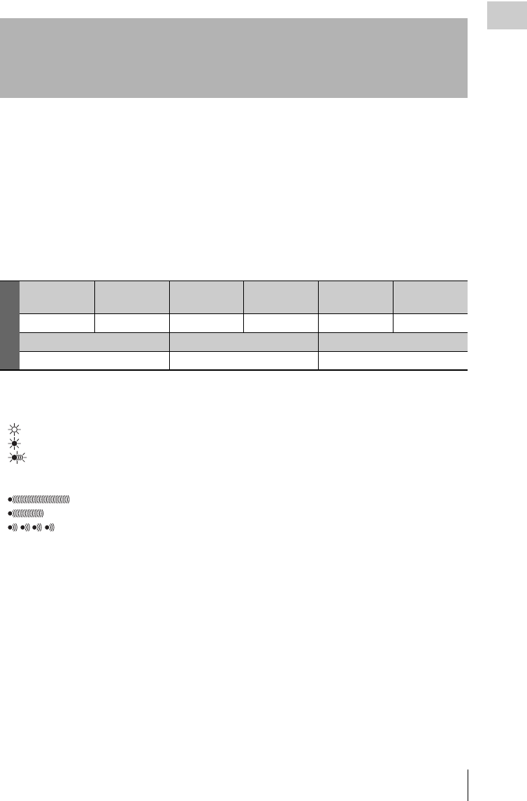
Operation Warnings 215
Chapter 9 Maintenance
If a problem occurs when the camcorder is
powered or is being operated, a warning is issued
by various visible and audible indicators. These
visible and audible indicators are:
• In the status display on the LCD monitor: a
warning message (“A” in the “Layout of the
table of warning messages” below) and a
warning indication (“B”)
• The WARNING indicator on the side panel of
the camcorder (“C”), and a warning sound from
the speaker and earphones (“D”)
• In the viewfinder: a warning message (“A”),
and an indicator above or below the viewfinder
screen (“E”)
The volume of the warning sound can be adjusted
with the ALARM knob. Set the ALARM knob to
the minimum position to suppress the sound.
Layout of the table of warning messages
• The operation of the WARNING indicator and
the indicators in the viewfinder is represented
by graphic symbols as follows.
: Continuous
: 1 flash/s
: 4 flashes/s
• The warning sounds are represented by graphic
symbols as follows.
: Continuous beep
: 1 beep/s
: 4 beeps/s
Operation Warnings
A
Warning
indication
State WARNING
indicator
Warning sound REC /TALY BATT
BCDEE
Problem VDR operation Action to take
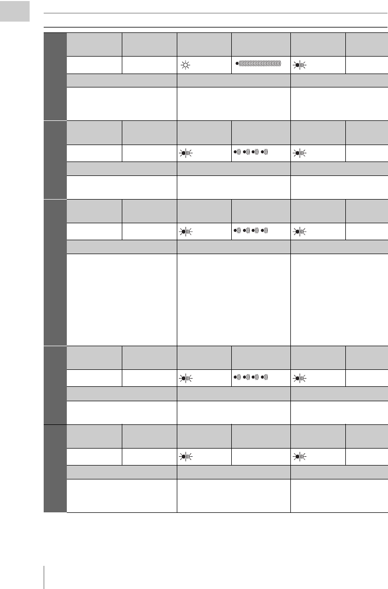
Operation Warnings
216
Chapter 9 Maintenance
Warning messages
Error**-** a)
Warning
indication
State WARNING
indicator
Warning sound REC/TALLY BATT
—— —
Problem VDR operation Action to take
Recording error Recording stops. Turn off the power and
consult a Sony service
representative.
MEM Full!
Warning
indication
State WARNING
indicator
Warning sound REC/TALLY BATT
—— b) b) b) —
Problem VDR operation Action to take
Shockproof memory overflow Recording continues but may be
substandard.
Protect the unit from shocks
and vibrations.
ILL REC!
Warning
indication
State WARNING
indicator
Warning sound REC/TALLY BATT
—— b) b) b) —
Problem VDR operation Action to take
Input sync error Recording continues but may be
substandard.
Turn off the power and
contact a Sony service
representative. (This
indication may be given
momentarily when a
GENLOCK signal is
connected or disconnected,
but this does not indicate a
problem.)
Verify ERR!
Warning
indication
State WARNING
indicator
Warning sound REC/TALLY BATT
—— b) b) b) —
Problem VDR operation Action to take
An error was detected in the
signals recorded on the disc.
Recording continues but may be
substandard.
Exchange the disc.
Cache Full!
Warning
indication
State WARNING
indicator
Warning sound REC/TALLY BATT
—— b) —b) —
Problem VDR operation Action to take
Cache memory became full
during a Disc Exchange Change
mode operation.
Video and audio recording may be
interrupted.
Exchange the disc quickly.
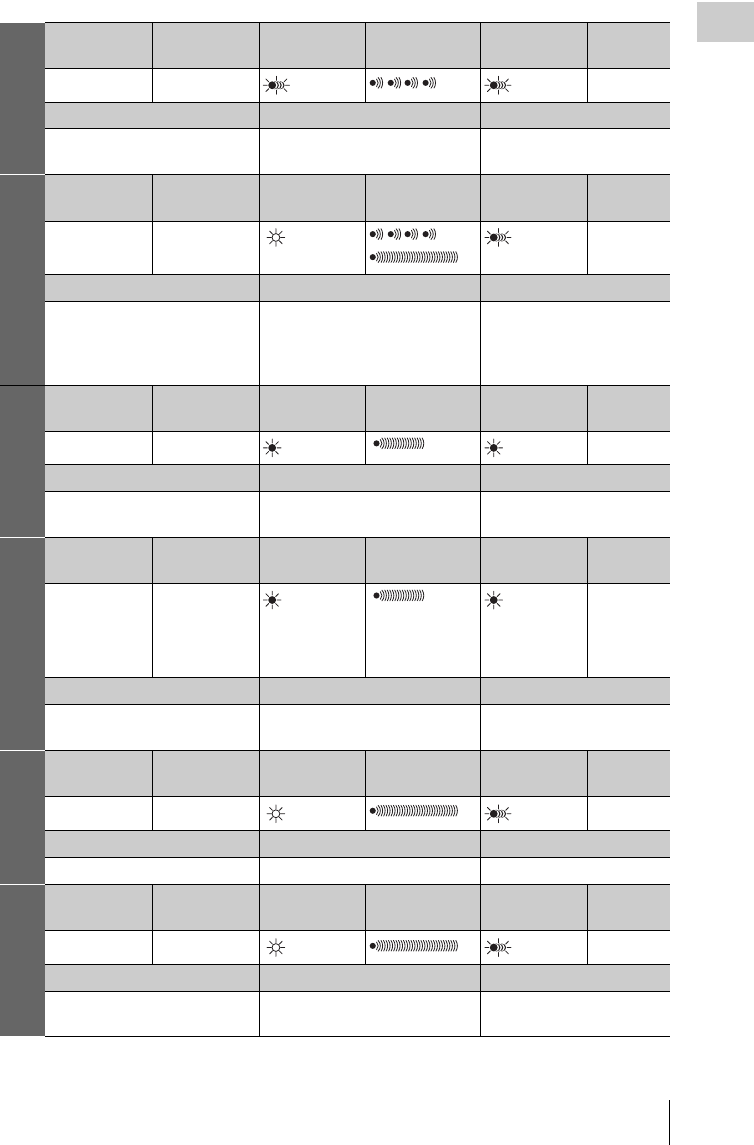
Operation Warnings 217
Chapter 9 Maintenance
Disc Error!
Warning
indication
State WARNING
indicator
Warning sound REC/TALLY BATT
—— b) b) b) —
Problem VDR operation Action to take
A disc defect was detected. Recording continues, avoiding the
defect, but may be substandard.
If defects are detected
repeatedly, exchange the disc.
HUMID!
Warning
indication
State WARNING
indicator
Warning sound REC/TALLY BATT
—— b) b)
c)
b) —
Problem VDR operation Action to take
Condensation on the optical
pickup
Recording/playback continues but
stops when an error occurs on the
drive.
Stop recording/ playback, turn
off the power, then turn it on
again, and wait until the
HUMID indicator disappears.
Before Full h)
Warning
indication
State WARNING
indicator
Warning sound REC/TALLY BATT
DISC flash f) b) b) —
Problem VDR operation Action to take
Disc almost full. Operation continues. Be prepared to exchange the
disc.
Near MAX #
Warning
indication
State WARNING
indicator
Warning sound REC/TALLY BATT
—— b)
(only when
recording the
300th clip) d)
—
Problem VDR operation Action to take
Nine or fewer clips remain until
the upper limit of 300 is reached.
Operation continues. Be prepared to exchange the
disc.
DISC FULL! d)
Warning
indication
State WARNING
indicator
Warning sound REC/TALLY BATT
DISC and E flash g) d) d) d) —
Problem VDR operation Action to take
Disc full. Recording stops. Exchange the disc.
MAX # Clips
Warning
indication
State WARNING
indicator
Warning sound REC/TALLY BATT
—— d) d) d) —
Problem VDR operation Action to take
The upper limit of 300 recorded
clips reached.
Cannot record. Exchange the disc.
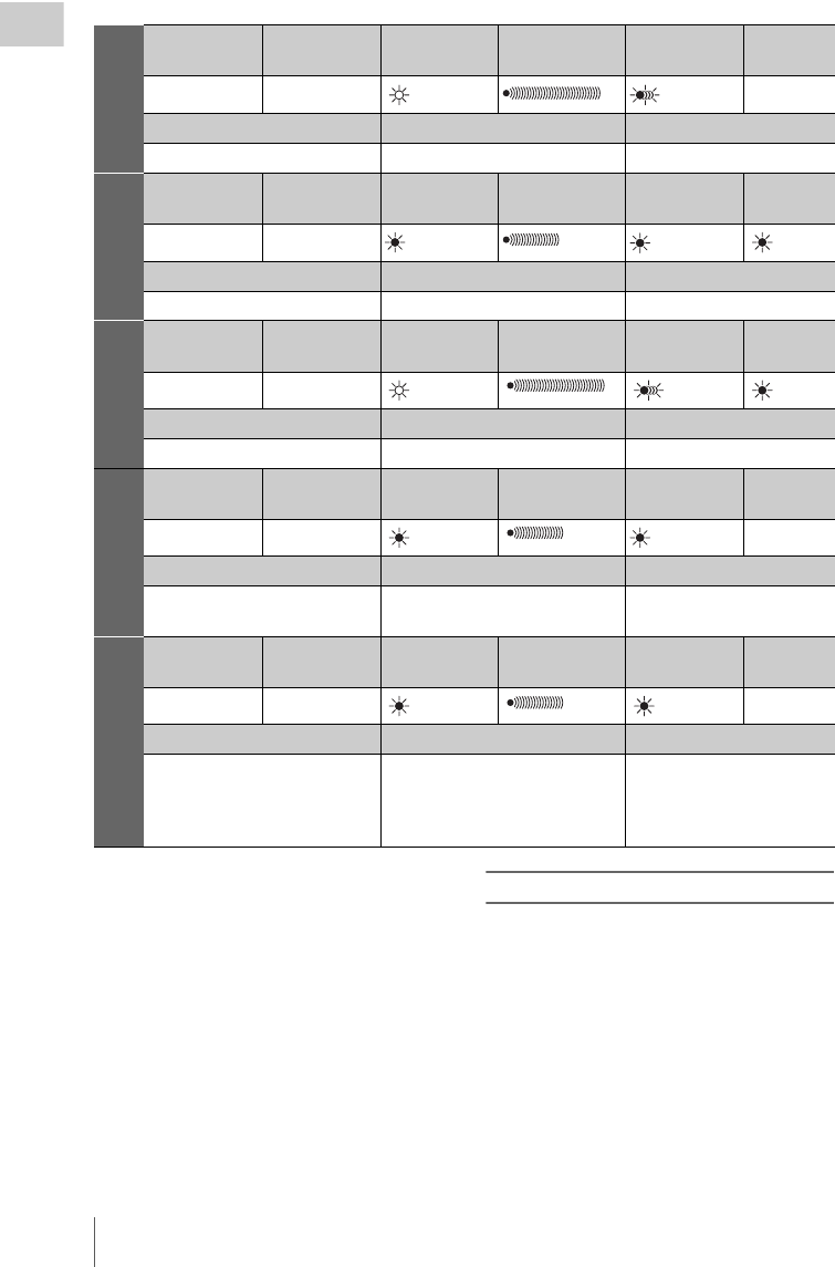
Operation Warnings
218
Chapter 9 Maintenance
a) Asterisks (*) are replaced by digits in the display.
b) During recording
c) During playback, fast forward, fast reverse, or stop
d) During recording pause
e) During recording or pause
f) 1 flash/s
g) 4 flashes/s
h) During recording, displayed in the LCD monitor only
(When the DISP SEL/EXPAND button is set to
STATUS)
For details about the warning displays and alarm
messages on the viewfinder, see the next item.
Operation/alarm messages
Operation and alarm messages are displayed in
the operation/alarm message display area (see
page 33) of the viewfinder screen.
MAX # Files
Warning
indication
State WARNING
indicator
Warning sound REC/TALLY BATT
—— d) d) d) —
Problem VDR operation Action to take
The upper limit of files reached. Cannot record. Exchange the disc.
LOW BATT! h)
Warning
indication
State WARNING
indicator
Warning sound REC/TALLY BATT
BATT flash f) e) e)
Problem VDR operation Action to take
Battery almost exhausted. Operation continues. Replace the battery.
BATT EMPTY!
Warning
indication
State WARNING
indicator
Warning sound REC/TALLY BATT
BATT and E flash g)
Problem VDR operation Action to take
Battery exhausted. Operation stops. Replace the battery.
High TEMP!
Warning
indication
State WARNING
indicator
Warning sound REC/TALLY BATT
—— —
Problem VDR operation Action to take
Internal temperature high. Operation continues. Power the unit off and move it
to a cool place.
ACC Sensor!/
Skew Sensor
Warning
indication
State WARNING
indicator
Warning sound REC/TALLY BATT
—— —
Problem VDR operation Action to take
Internal drive sensor error Operation continues. Protect the unit from shocks
and vibrations, turn off the
power, and contact a Sony
service representative.

Operation Warnings 219
Chapter 9 Maintenance
a) Contact a Sony service representative to replace the
battery.
VDR operation messages are displayed in the
setting change and adjustment progress message
display area of the viewfinder screen (see
page 34). Take the actions listed in the following
table.
AUTO
INTERVAL
**M**S
The unit is operating in Auto
Interval Rec mode (**M**S:
Indicates the shooting interval in
minutes and seconds).
MANU
INTERVAL
*FRAME
The unit is operating in the single-
shot mode of Manual Interval Rec
mode (*FRAME: Indicates the
number of frames recorded in one
shot).
INTERVAL
**S (M/H)
*FRAME
The unit is operating in the
consecutive mode of Manual
Interval Rec mode (**S (M/H):
Indicates the trigger interval, in
seconds (minutes or hours),
*FRAME: Indicates the number
of frames recorded in one shot).
LOW LIGHT Depending on the setting, the
subject illumination is inadequate.
ON-BOARD
BATTERY
EMPTY
The backup battery of the internal
clock is empty. a)
DCP
EEPROM
DATA NG!
DR EEPROM
DATA NG!
DCP/DR
EEPROM
DATA NG!
If this message continues to
appear even after the unit is
powered off and on again several
times, then the factory adjustment
data is invalid. Contact a Sony
service representative.
ILL. Disc! A disc that cannot be used by this
unit was inserted. Insert another
Professional Disc.
ILL. Index!
No FS!
Unknown FS!
Index file or file system error.
Exchange or format the disc.
No Support! A recorded clip cannot be handled
by this unit. Exchange or format
the disc.
FORMAT
NG!
The disc could not be formatted
automatically. Exchange the disc.
Disc Damage A disc that cannot be recorded was
inserted. To record, exchange the
disc.
Non AV Full
MAX # Files
Over DUR!
The disc is full. Exchange or
format the disc.
DI read err
Read err
DRV ADJ err
The disc was not recognized. Try
ejecting the disc and inserting it
again. Or exchange the disc.
Run Salvage A disc that requires salvage was
inserted. To record on the disc,
eject the disc, insert it again, and
execute salvage processing.
Salvage NG! Salvage processing failed.
For details, see “Handling of discs
when recording does not end
normally (salvage function)” on
page 74.
Salvage
XXXX
The loaded disc cannot be
salvaged by this unit. The
“XXXX” in the message is a code
for XDCAM devices that can
salvage the disc. Refer to the list
of device codes (see page 75) and
salvage the disc using one of the
indicated devices.
REC INHI.! The Write Inhibit tab of the disc is
in the recording disabled position,
or salvage processing needs to be
done on the loaded disc. Set the
tab to the recording enabled
position. Or eject the disc, insert it
again, and perform salvage
processing.
1080/50i
1080/25P
1080/59.94i
1080/29.97P
720/50P
720/59.94P
625/50i
525/59.94i
The loaded disc has a different
resolution or a different system
frequency. To carry out recording
operations, exchange the disc, or
change the resolution or system
frequency.

Operation Warnings
220
Chapter 9 Maintenance
HD422 1080
HD422 720
HD420 1080
HD420 720
IMX50 Clip
IMX40 Clip
IMX30 Clip
DVCAM
8CHx16 Clip
4CHx24 Clip
2CHx16 Clip
The loaded disc has a different
recording format. To carry out
recording operations, exchange
the disc, or change the recording
format.
Index File! There is an unsupported index file
on the disc to which you are trying
to record. Exchange or format the
disc.
File System There is an unsupported file
system on the disc to which you
are trying to record. Exchange or
format the disc.
ILL. PLAY! An A/V phase error occurred
during playback. Stop the disc.
Lid Closed! The lid of the disc compartment
does not open. Check the lid.
Lid Open! The lid of the disc compartment is
not closed. Close it securely.
No Clip! There are no clips recorded on the
disc. Exchange for a recorded
disc.
No Disc! There is no disc loaded. Insert a
disc and try the operation again.
STOP ONCE!
REC mode!
The operation is not possible
while the disc is being played or
recorded. Stop the disc.
Loading!
Unloading!
An operation was attempted while
a disc was loading or unloading.
Wait for the disc to finish loading
or unloading and try again.
Disc Top!
Disc End!
The operation is not possible
because the disc is at the top or
end.
Formatting! The disc is being automatically
formatted. Wait until the format
ends.
Recording The unit is writing to the file
system. Wait until writing
finishes.
No EM Space
EM Full!
Essence marks cannot be inserted.
For details, see “Recording
essence marks” on page 80.
Cache REC! An attempt was made to perform
an operation that cannot be
performed when the picture cache
function is enabled. The operation
will be ignored.
Disc Exchag! An attempt was made to perform
an operation that cannot be
performed when the disc exchange
cache function is enabled. The
operation will be ignored.
SB CLP mode An essence mark or clip flag
operation was attempted while the
SUB CLIP indicator was lit. Press
the SUB CLIP/DISC MENU
button to turn the indicator off and
try again.
No SEL List No clip list is selected. Create a
new clip list, or load a clip list
from the disc.
No List! There is no clip list. Create a clip
list.
No SUB Clip There are no sub clips in the clip
list. Register a sub clip, or load
another clip list.
SUB Clip NG The In and Out point positions are
invalid. Set correct In and Out
points.
MAX# SB
CLP
The total number of sub clips is
over the upper limit (300).
CL OVER
DUR
The total duration of sub clips in
the current clip list is over the
upper limit (24 hours).
FAN Stopped
DR-FAN Stop
The main unit or drive fan has
stopped. Avoid use under high
temperatures, turn off the power,
and contact a Sony service
representative.
NVRAM NG! An error was detected while
accessing internal memory. Power
the unit off and contact a Sony
service representative.
Update Err! A firmware update failed. Power
the unit off and contact a Sony
service representative.
Unknown
USB
An unsupported USB device was
connected to this unit.

Operation Warnings 221
Chapter 9 Maintenance
Alarm messages during thumbnail
search, scene selection, and clip list
operations
An alarm message may appear in the LCD
monitor during thumbnail search, scene selection,
and clip list operations. In that case, take the
action indicated in the following table.
Cannot
Expand Clip
any Further.
The clip cannot be expanded into
more blocks. This alarm appears
when the DISP SEL/EXPAND
button is pressed when the number
of blocks is maximum, or when
the duration of an expanded
thumbnail is one frame.
Selected
Essence Mark
Does not
Exist.
The selected essence mark does
not exist.
This alarm appears in the essence
mark selection screen when the
specified essence mark does not
exist on the disc.
Sub Clip is
Invalid. Set
Appropriate
IN/OUT
Points.
The temporal relationship between
the specified In and Out points in a
TRIM operation (see page 117) is
not correct. Reset so that the value
of the Out point timecode is larger
than the value of the In point
timecode.
Duration of
One Clip List
must be Less
than 24
Hours.
The total duration of the current
clip list exceeds the upper limit of
24 hours as the result of an Add
Sub Clips (see page 115) or Trim
Sub Clip (see page 117) operation.
No More Sub
Clips can be
Added to the
Clip List.
The total number of the sub clips
of the current clip list exceeds the
upper limit of 300 as the result of
an Add Sub Clips (see page 115)
or Trim Sub Clip (see page 117)
operation.
Sub Clip does
not Exist.
An attempt is made to execute a
Move Sub Clips (see page 116),
Trim Sub Clip (see page 117),
Delete Sub Clips (see page 117),
or Set Start Time Code (see
page 118) operation with no sub
clips in the current clip list.
Clip List does
not Exist.
An attempt is made to execute a
Delete Clip List operation (see
page 120) when there are no clip
lists on the disc.
Move is
Invalid.
An attempt is made to execute a
Move Sub Clips operation (see
page 116) when there are no sub
clip in the current clip list, or when
there is only one.
Shot Mark
does not
Exist.
An attempt is made to execute a
Delete Shot Mark (see page 106)
operation on a clip with no shot
marks recorded in.
Chapter does
not Exist.
An attempt was made to display a
nonexistent chapter.
Rec Start
cannot be
Deleted.
An attempt is made to delete a Rec
Start with a Delete Shot Mark
operation. Only Shot Mark1 and
Shot Mark2 essence marks can be
deleted.
Rec Start
cannot be
Moved.
An attempt was made to move a
Rec Start essence mark with a
Move Shot Mark operation. Only
Shot Mark1 and Shot Mark2
essence marks can be moved.
Command
Disabled.
An attempt was made to execute
the Format Disc command with
Disable “Format Disc” set to
“Disable”.
Clip is
Locked.
An attempt is made to delete a
clip, set the clip thumbnail, or
delete a shot mark when the clip is
locked.
All Clips are
Locked.
An attempt is made to execute a
Lock All Clips operation when all
clips are already locked.
All Clips are
Unlocked.
An attempt is made to execute an
Unlock All Clips operation when
all clips are already unlocked.
A File with
the Name you
Specified
Already
Exists.
Specify a
Different
Name.
A file name that was specified in a
Set Clip Name operation already
exists.
Set NAMING
FORM to
“free”
An attempt was made to rename a
clip with Set Clip Name when
NAMING FORM is not set to
“FREE” (see page 91).

Operation Warnings
222
Chapter 9 Maintenance
“No Flash
Drive”
In the media selection screen of
the Load Planning Metadata/
Select Drive command, “USB
Flash Drive” was selected with no
USB flash drive connected.

Important Notes on Operation 223
Appendix
Use and storage
Do not subject the unit to severe shocks
The internal mechanism may be damaged or the
body warped.
Do not cover the unit while operating
Putting a cloth, for example, over the unit can
cause excessive internal heat build-up.
After use
Always turn off the POWER switch.
Before storing the camcorder for a long period
Remove the battery pack.
Shipping
• Remove the disc before transporting the unit.
• If sending the unit by truck, ship, air or other
transportation service, pack it in the shipping
carton of the unit.
Care of the unit
Remove dust and dirt from the surfaces of the
lenses or optical filters using a blower.
If the body of the unit is dirty, clean it with a soft,
dry cloth. In extreme cases, use a cloth steeped in
a little neutral detergent, then wipe dry. Do not
use organic solvents such as alcohol or thinners,
as these may cause discoloration or other damage
to the finish of the unit.
In the event of operating problems
If you should experience problems with the unit,
contact a Sony representative.
Use and storage locations
Store in a level, ventilated place. Avoid using or
storing the unit in the following places.
• In excessive heat or cold (operating temperature
range: 0°C to 40°C (32°F to 104°F))
• Remember that in summer in warm climates the
temperature inside a car with the windows
closed can easily exceed 50°C (122°F).
• In damp or dusty locations
• Locations where the unit may be exposed to rain
• Locations subject to violent vibration
• Near strong magnetic fields
• Close to radio or TV transmitters producing
strong electromagnetic fields.
• In direct sunlight or close to heaters for
extended periods
To prevent electromagnetic interference from
portable communications devices
The use of portable telephones and other
communications devices near this unit can result
in malfunctions and interference with audio and
video signals.
It is recommended that the portable
communications devices near this unit be
powered off.
Note on laser beams
Laser beams may damage the CCDs.
If you shoot a scene that includes a laser beam, be
careful not to let the laser beam be directed into
the lens of the camera.
Condensation
If you move the camcorder from a very cold place
to a warm place, or use it in a damp location,
condensation may form on the optical pickup.
Then, if the camcorder is operated in this state,
recording and playback may not be performed
properly.
Do the following to prevent this from happening.
• When you move or operate the camcorder in an
environment where condensation may form, be
sure to load a disc in advance and close the disc
compartment lid.
• Whenever you turn on the power, check that the
HUMID indicator does not appear on the color
LCD. If it appears, wait until it disappears
before loading a disc.
For details, see “Loading and unloading a disc” on
page 73 and “Operation Warnings” on page 215.
Appendix
Important Notes on
Operation
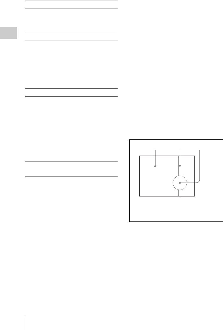
Important Notes on Operation
224
Appendix
Fitting the zoom lens
It is important to fit the lens correctly, as
otherwise damage may result. Be sure to refer to
the section “Mounting the Lens” on page 42.
Viewfinder
• Do not leave the unit with the eyepiece pointing
directly at the sun.
The eyepiece lens can concentrate the sun’s
rays and melt the interior of the viewfinder.
• Do not use the viewfinder close to strong
magnetic fields. This can cause picture
distortion.
About the LCD panels
LCD panels are manufactured with extremely
high-precision technology that yields effective
pixel rates of 99.99% or higher. However, very
rarely, one or more pixels may be permanently
dark or permanently lit in white, red, blue, or
green.
This phenomenon is not a malfunction. Such
pixels have no effect on the recorded data, and the
unit may be used with confidence even if they are
present.
Phenomena specific to CCD image
sensors
The following phenomena that may appear in
images are specific to CCD (Charge Coupled
Device) image sensors. They do not indicate
malfunctions.
White flecks
Although the CCD image sensors are produced
with high-precision technologies, fine white
flecks may be generated on the screen in rare
cases, caused by cosmic rays, etc.
This is related to the principle of CCD image
sensors and is not a malfunction.
The white flecks especially tend to be seen in the
following cases:
• When operating at a high environmental
temperature
• When you have raised the master gain
(sensitivity)
The problem may be alleviated by executing the
APR (automatic pixel noise reduction) function
on the APR page of the MAINTENANCE menu
(see page 156). Pixel noise is reduced to some
extent by automatic black balance adjustment
(see page 55), but the detection capabilities of
that function are limited. For the most effective
correction, execute the APR function.
If “No More White Pixel” appears after the APR
function is executed, then there are no more
detectable white flecks.
In SLS mode, white flecks are more prominent
when you set the shutter speed (number of
frames) to higher values. Executing the
APR(SLS) function on the APR page (see page
156) may alleviate the problem of white flecks in
SLS mode.
Vertical smear
When an extremely bright object, such as a strong
spotlight or flashlight, is being shot, vertical tails
may be produced on the screen, or the image may
be distorted.
Aliasing
When fine patterns, stripes, or lines are shot, they
may appear jagged or flicker.
123
1Monitor screen
2Vertical tails shown on the image
3Bright object (e.g. strong spotlight,
strong reflected light, flashlight, the sun)
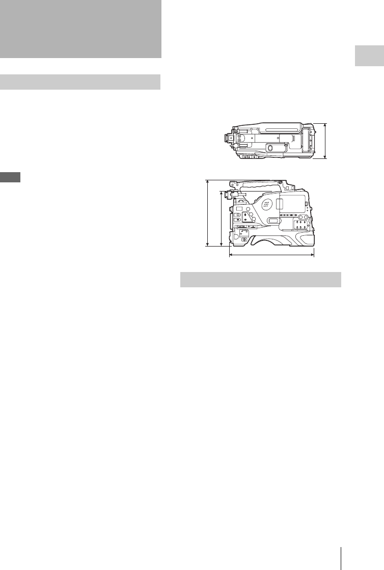
Specifications 225
Appendix
Power voltage
12 V DC +5.0/–1.0 V
Power consumption
Approx. 40 W 1)
Approx. 44 W 2)
Approx. 46 W 3)
Note
Do not allow the total power consumption of this unit
and peripherals to exceed 100 W when peripherals are
connected.
However, power consumed by the HDCA-702 MPEG
TS Adaptor is not counted in the total power
consumption.
1) Recording, main unit only, power from battery pack,
VDR SAVE/STBY switch set to SAVE, LCD monitor
on (backlight: low).
2) Recording, options installed (HDVF-20A viewfinder,
ECM-680S microphone, lens), power from battery
pack, VDR SAVE/STBY switch set to SAVE, LCD
monitor on (backlight: low).
3) Recording, options installed (HDVF-20A viewfinder,
ECM-680S microphone, lens), DC power, VDR
SAVE/STBY switch set to STBY, LCD monitor on
(backlight: high).
Operating temperature
–5°C to +40°C (23°F to 104°F)
Operating humidity
10% to 90% (relative humidity)
Storage temperature
–20°C to +60°C (–4°F to +140°F)
Recording format
Video: MPEG HD 422 50 Mbps
Proxy video: MPEG-4
Audio: MPEG HD 422: 4 channels, 24
bits/48 kHz
Proxy audio: A-law, 4 channels, 8 bits/8
kHz
Continuous operating time
Approx. 120 min. (with BP-GL95)
Mass
Approx. 4.3 kg (9 lb 7 oz) (main body
only)
Approx. 6.0 kg (13 lb 3 oz) (with
HDVF-20A viewfinder, ECM-680S
microphone, disc and BP-GL95
Battery Pack)
Dimensions in mm (inches)
Imager
2/3-inch type, 1920 (H) × 1080 (V)
Imager Configuration
RGB 3 CCDs
Spectral system
F1.4 prism system (with quartz filter)
Built-in filters
ND filter (optical)
1: Clear
2: 1/4 ND
3: 1/16 ND
4: 1/64 ND
Lens mount
2/3-inch 48 bayonet mount
Sensitivity
F11 (system frequency: 59.94i)
F12 (system frequency: 50i)
(89.9% reflection chart, 2000 lx)
Specifications
General
Video camera section
222(8 3/4)
269(10 5/8)
124(5)
332(13 1/8)

Specifications
226
Appendix
Minimum illumination
0.016 1x (F1.4, +42 dB, with 16-frame
accumulation)
Video S/N ratio
59 dB (With noise suppression on. Off
value is 54 dB.)
Modulation (at screen center)
45% or more
Registration
0.02% or less for entire screen area
(excluding distortion due to lens)
Geometric distortion
None identified (excluding distortion
due to lens)
Smear
–135 dB
LCD panel
3.5 inches
Pixel resolution: 250,880 pixels
General
Usable disc
PFD50DLA Professional Disc
(capacity: 50.0 GB)
PFD23A Professional Disc (capacity:
23.3 GB)
Data transfer rate
Max. 72 Mbps
Recording/playback time
MPEG IMX 50 Mbps
PFD50DLA: Approx. 95 minutes
PFD23A: Approx. 43 minutes
Digital video
Sampling frequency
Y: 74.176 MHz (59.94i), 74.25 MHz
(50i/25P)
Pb/Pr: 37.088 MHz (59.94i), 37.125
MHz (50i/25P)
Quantization
8 bits/sample
Compression
MPEG-2 4:2:2P@HL 50 Mbps
Audio (with standard playback machine)
Frequency response
20 Hz to 20 kHz, +0.5 dB/–1.0 dB
Dynamic range
93 dB min.
Distortion (THD)
0.08% max.
Cross talk
–70 dB max.
Wow and flutter
Below measurable limit
Input/output connectors
Signal inputs
AUDIO IN CH1/CH2: XLR type, 3-pin,
female
–60 dBu/+4 dBu (0 dBu = 0.775 Vrms)
MIC IN: XLR type, 5-pin, female
–60 dBu
GENLOCK IN: BNC type
1.0 Vp-p, 75 Ω, unbalanced
TC IN: BNC type
0.5 V to 18 Vp-p, 10 kΩ
Signal outputs
TEST OUT: BNC type
VBS/Y (component): 1.0 Vp-p, 75 Ω,
unbalanced
SDI OUT 1/2: BNC type
HD-SDI/SD-SDI: 0.8 Vp-p, unbalanced
AUDIO OUT: XLR type, 5-pin, male
0 dBm
TC OUT: BNC type
1.0 Vp-p, 75 Ω
EARPHONE (minijack)
8 Ω, –∞ to –18 dBs variable
Others
DC IN: XLR type, 4-pin, male
11 to 17 V DC
Optical disc drive section

Specifications 227
Appendix
DC OUT: 4-pin
11 to 17 V DC, maximum rated current
0.5 A
LENS: 12-pin
REMOTE: 8-pin
LIGHT: 2-pin
(i.LINK) S400: 6-pin, complies with IEEE
1394
(network): RJ-45 type
100BASE-TX: Complies with
IEEE802.3u
10BASE-T: Complies with IEEE802.3
USB 2.0: HOST Type-A, 4-pin (for maintenance)
Shoulder strap (1)
Microphone cable (for converting 3-pin
connector to two 5-pin connectors) (1)
Operation manuals
English version (1)
Japanese version (1)
CD-ROM manual (1)
XDCAM Application Software CD-ROM (1)
Power supply and related equipment
BP- GL65/GL95/L60S/L80S Battery Pack
BC-M150/L500/L70 Battery Charger
AC-DN10/DN2B AC Adaptor
Viewfinder and related equipment
HDVF-20A/200/C35W Viewfinder
BKW-401 Viewfinder Rotation Bracket
Note
Contact a Sony service representative for information
about the viewfinders able to use the BKW-401.
Equipment for remote control
RM-B150/B750 Remote Control Unit
“Memory Stick”
“Memory Stick”
“Memory Stick PRO” (4 GB or less)
“Memory Stick Duo”
“Memory Stick PRO Duo”
Audio equipment
ECM-680S Stereo/Monaural Microphone
ECM-678/674 Monaural Microphone
CAC-12 Microphone Holder
DWR-S01D Digital Wireless Receiver
WRR-855S UHF Synthesized Tuner Unit
WRR-860A/861/862 UHF Synthesized Diver-
sity Tuner
WRT-850/860 UHF Synthesized Transmitter
DWT-B01 Digital Wireless Transmitter
DMX-P02 Portable Digital Mixer
Expansion boards and upgrade software
CBK-HD01 HD/SD SDI Input Board
CBK-SC02 Analog Composite Input Board
CBKZ-MD01 SD Record and Playback Soft-
ware
Other peripheral devices
HDCA-702 MPEG TS Adaptor
Equipment for maintenance and easier
handling
LC-777 Hard Carrying Case
LC-DS300SFT Soft Carrying Case
VCT-14 Tripod Adaptor
Maintenance Manual
Supplied accessories
Recommended additional
equipment

Specifications
228
Appendix
Design and specifications are subject to change
without notice.
Notes
• Always make a test recording, and verify that
it was recorded successfully.
SONY WILL NOT BE LIABLE FOR
DAMAGES OF ANY KIND INCLUDING,
BUT NOT LIMITED TO, COMPENSATION
OR REIMBURSEMENT ON ACCOUNT OF
FAILURE OF THIS UNIT OR ITS
RECORDING MEDIA, EXTERNAL
STORAGE SYSTEMS OR ANY OTHER
MEDIA OR STORAGE SYSTEMS TO
RECORD CONTENT OF ANY TYPE.
• Always verify that the unit is operating
properly before use. SONY WILL NOT BE
LIABLE FOR DAMAGES OF ANY KIND
INCLUDING, BUT NOT LIMITED TO,
COMPENSATION OR REIMBURSEMENT
ON ACCOUNT OF THE LOSS OF
PRESENT OR PROSPECTIVE PROFITS
DUE TO FAILURE OF THIS UNIT, EITHER
DURING THE WARRANTY PERIOD OR
AFTER EXPIRATION OF THE
WARRANTY, OR FOR ANY OTHER
REASON WHATSOEVER.
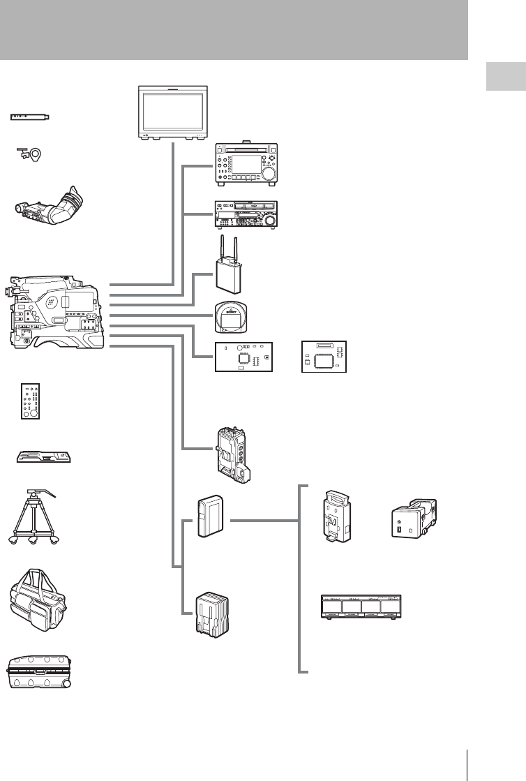
Chart of Optional Components and Accessories 229
Appendix
Chart of Optional Components and Accessories
a) The carrying case is large enough to hold the camcorder with lens and microphone mounted.
However, remove them if they protrude more than 25 cm from the front of the main unit.
ECM-680S/678/
674 Microphone
CAC-12
Microphone Holder
HDVF-20A/200/
C35W Viewfinder
LCD monitor
BVM-L230, LMD series monitor
XDCAM HD series recorder
PDW-HD1500, PDW-F75
HDCAM series recorder
HDW-2000 series recorder, HDW-S280
WRR-855S UHF Synthesized Tuner Unit
DWR-S01D Digital Wireless Receiver
PDW-700
RM-B150/B750
Remote Control Unit
VCT-14 Tripod
adaptor
Tripod
LC-DS300 SFT
Soft carrying
case a)
LC-777 Hard
carrying case
AC-DN10/DN2B
AC Adaptor
BC-L500 Battery
Charger
BC-M150
Battery
Charger
BC-L70
Battery
Charger
BP-GL95/GL65/
L60S/L80S
Battery Pack
PFD23A/PFD50DLA Professional disc
CBK-HD01
HD/SD SDI
Input Board
CBK-SC02
Analog
Composite
Input Board
CBKZ-MD01
SD Record
and Playback
Software
HDCA-702
MPEG TS Adaptor

Using PDZ-1 Proxy Browsing Software
230
Appendix
When a computer with the PDZ-1 Proxy
Browsing Software installed is connected to this
unit, you can transfer the proxy AV data and
metadata files recorded on a disc to the computer.
On the computer side, PDZ-1 enables you to
browse the proxy AV data, add or modify
metadata (titles, comments, essence marks, etc.),
or create a clip list.
The modified metadata and the created clip list
can then be written back to the disc loaded in this
unit.
For more information about PDZ-1 functions and
operations, refer to the PDZ-1 help.
System requirements
The following are required to use PDZ-1.
Computer: PC with Intel Pentium M processor,
at least 1 GHz (installed memory: at least 512
MB)
Operating system: Microsoft Windows XP
Professional SP2 or higher, Windows Vista
Ultimate/Business (32 bit), or Mac OS X
v10.4.11 or higher
Web browser: Internet Explorer 6.0 SP1 or
higher
DirectX: DirectX 8.1b or higher
To install PDZ-1
Insert the supplied CD-ROM (XDCAM
Application Software) into the CD-ROM drive of
your computer, and run the installer in the PDZ-1
directory.
For details, refer to the ReadMe file contained on the
CD-ROM disc.
Notes
• Make sure that the hard disk drive on which the work
folder to store the material transferred from this unit
has adequate free space.
• To transfer files between the computer and this unit
requires this unit's IP address and other network-
related settings to be made.
Using PDZ-1 Proxy
Browsing Software
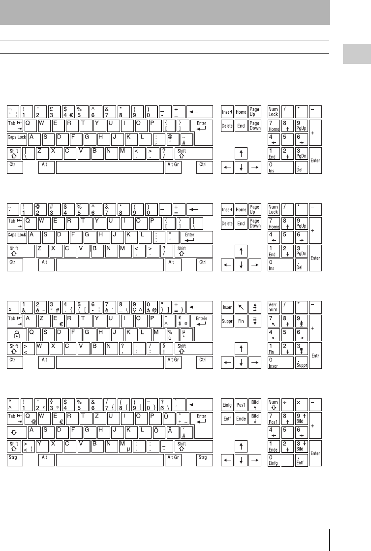
List of Supported USB Keyboards 231
Appendix
When the area of use is set to NTSC AREA or PAL AREA
On this unit, you can enter any of the characters
and symbols supported by the keyboards listed
below.
Select the corresponding language by selecting
Settings >Select USB Keyboard Language in the
Disc Menu (see page 110).
English [United Kingdom]
English [United States]
French [France]
German [Germany]
List of Supported USB Keyboards
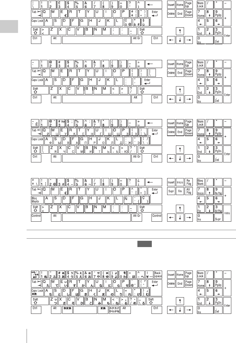
List of Supported USB Keyboards
232
Appendix
Italian [Italy]
Polish (Programmers) [Poland]
Russian [Russia]
Spanish [Spain]
When the area of use is set to NTSC(J) AREA
The keyboard is fixed as the Japanese keyboard. Notes
• The keyboard language cannot be changed.
• It is not possible to enter Japanese hiragana, katakana,
and kanji.

Trademarks and Licenses 233
Appendix
THIS PRODUCT IS LICENSED UNDER THE
MPEG-4 VISUAL PATENT PORTFOLIO
LICENSE FOR THE PERSONAL AND NON-
COMMERCIAL USE OF A CONSUMER FOR
(i) ENCODING VIDEO IN COMPLIANCE
WITH THE MPEG-4 VISUAL STANDARD
(“MPEG-4 VIDEO”)
AND/OR
(ii) DECODING MPEG-4 VIDEO THAT WAS
ENCODED BY A CONSUMER ENGAGED IN
A PERSONAL AND NON-COMMERCIAL
ACTIVITY AND/OR WAS OBTAINED FROM
A VIDEO PROVIDER LICENSED BY MPEG
LA TO PROVIDE MPEG-4 VIDEO.
NO LICENSE IS GRANTED OR SHALL BE
IMPLIED FOR ANY OTHER USE.
ADDITIONAL INFORMATION INCLUDING
THAT RELATING TO PROMOTIONAL,
INTERNAL AND COMMERCIAL USES AND
LICENSING MAY BE OBTAINED FROM
MPEG LA, LLC. SEE HTTP://
WWW.MPEGLA.COM
MPEG LA is offering licenses for (i) manufacturing/
sales of any storage media storing MPEG-4 Visual video
information (ii) distribution/broadcasting of MPEG-4
Visual video information in any manner (such as online
video distribution service, internet broadcasting, TV
broadcasting). Other usage of this product may be
required to obtain license from MPEGLA. Please contact
MPEG LA for any further information. MPEG LA,
L.L.C., 250 STEELE STREET, SUITE 300, DENVER,
COLORADO 80206, http://www.mpegla.com
ANY USE OF THIS PRODUCT OTHER THAN
CONSUMER PERSONAL USE IN ANY
MANNER THAT COMPLIES WITH THE
MPEG-2 STANDARD FOR ENCODING
VIDEO INFORMATION FOR PACKAGED
MEDIA IS EXPRESSLY PROHIBITED
WITHOUT A LICENSE UNDER
APPLICABLE PATENTS IN THE MPEG-2
PATENT PORTFOLIO, WHICH LICENSE IS
AVAILABLE FROM MPEG LA, L.L.C., 250
STEELE STREET, SUITE 300, DENVER,
COLORADO 80206.
“PACKAGED MEDIA” means any storage media
storing MPEG-2 video information such as DVD movie
which are sold/distributed to general consumers. Disc
replicators or sellers of the PACKAGED MEDIA need
to obtain licenses for their own business from MPEG
LA. Please contact MPEG LA for any further
information. MPEG LA, L.L.C., 250 STEELE STREET,
SUITE 300, DENVER, COLORADO 80206
http://www.mpegla.com
This software is based in part on the work of the
Independent JPEG.
This product includes technology from Monotype
Imaging Inc., including iType® and certain fonts.
Trademarks and
Licenses
MPEG-4 Visual Patent Portfolio
License
MPEG-2 Video Patent Portfolio
License
About IJG (Independent JPEG
Group)
Character display software
“iType”
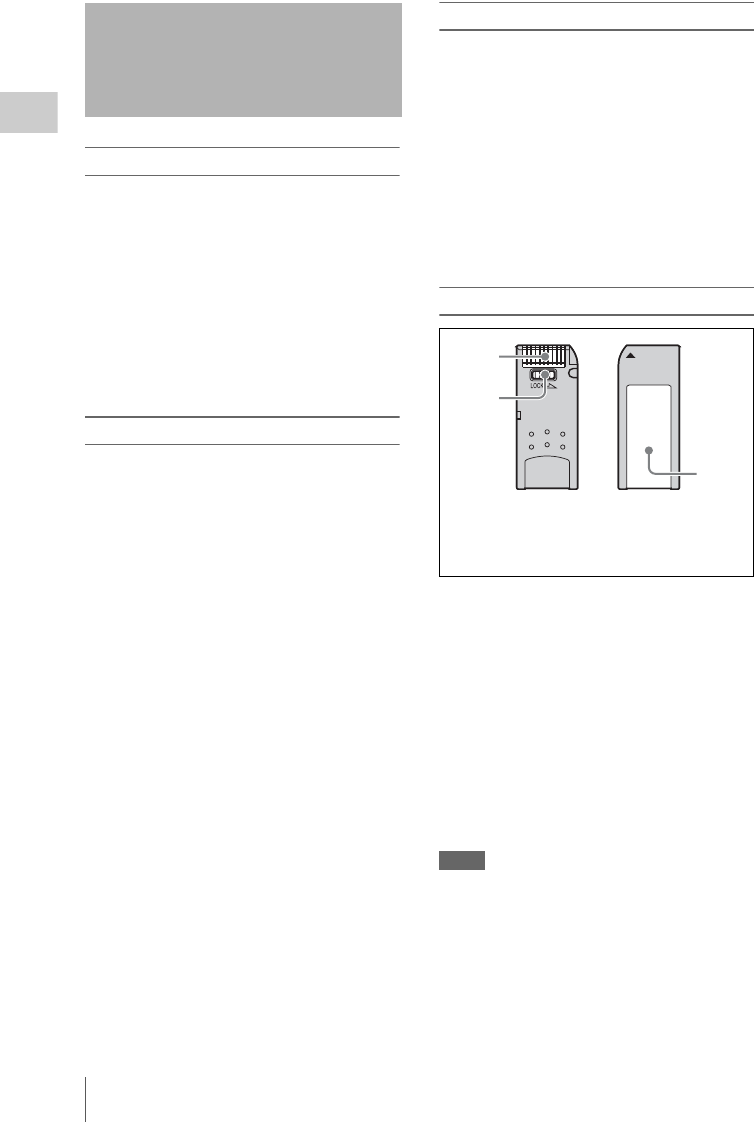
About a “Memory Stick”
234
Appendix
What is “Memory Stick”?
“Memory Stick” is a new compact, portable and
versatile IC (Integrated Circuit) recording
medium with a data capacity that exceeds a
floppy disk. “Memory Stick” is specially
designed for exchanging and sharing digital data
among “Memory Stick” compatible products.
Because it is removable, “Memory Stick” can
also be used for external data storage.
“Memory Stick” is available in two sizes:
standard size and compact “Memory Stick Duo”
size.
Types of “Memory Stick”
“Memory Stick” is available in the following five
types to meet various requirements in functions.
“Memory Stick-R”
Stored data are not overwritten. You can write
data to “Memory Stick-R” with “Memory Stick-
R” compatible products only. Copyright
protected data that requires MagicGate copyright
protection technology cannot be written to
“Memory Stick-R”.
“Memory Stick”
Stores any type of data except copyright-
protected data that requires the MagicGate
copyright protection technology.
“MagicGate Memory Stick”
Equipped with the MagicGate copyright
protection technology.
“Memory Stick-ROM”
Stores pre-recorded, read-only data. You cannot
record on “Memory Stick-ROM” or erase the pre-
recorded data.
“Memory Stick PRO”
Equipped with the MagicGate copyright
protection technology, designed for use only with
equipment compatible with “Memory Stick
PRO”.
Available types of “Memory Stick”
With this camcorder, you can use a Sony
“Memory Stick”, “Memory Stick Duo”,
“Memory Stick PRO” whose capacity does not
exceed 4 GB, and “Memory Stick PRO Duo”.
Note on data read/write speed
Data read/write speed may vary depending on the
combination of the “Memory Stick” and
“Memory Stick” compliant product you use.
What is MagicGate?
MagicGate is copyright protection technology
that uses encryption technology.
Before using a “Memory Stick”
• When you set the “Memory Stick” write-protect
tab to “LOCK”, data cannot be recorded, edited,
or erased. (“Memory Stick Duo” and “Memory
Stick PRO Duo” do not have this function.)
• Data may be damaged if:
- You remove the “Memory Stick” or turn off
the unit while it is reading or writing data.
- You use the “Memory Stick” in a location
subject to the effects of static electricity or
electric noise.
• We recommend that you make a backup copy of
important data that you record on the “Memory
Stick”.
Notes
• Do not attach anything other than the supplied label to
the “Memory Stick” labeling position.
• Attach the label so that it does not stick out beyond the
labeling position.
• Carry and store the “Memory Stick” in its case.
• Do not touch the connector of the “Memory Stick”
with anything, including your finger or metallic
objects.
• Do not strike, bend, or drop the “Memory Stick”.
About a “Memory Stick”
3
2
1
1Terminal
2Write-protect tab
3Labeling position
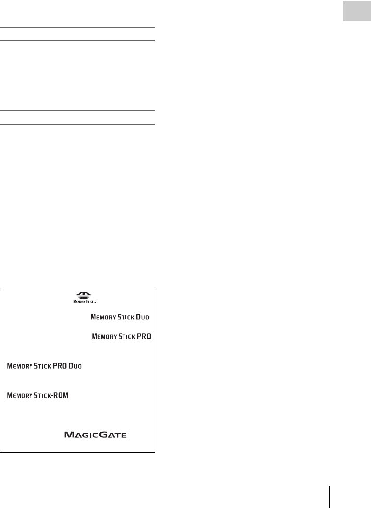
About a “Memory Stick” 235
Appendix
• Do not disassemble or modify the “Memory Stick”.
• Do not allow the “Memory Stick” to get wet.
• Do not use or store the “Memory Stick” in a location
that is:
- Extremely hot, such as in a car parked in the sun
- Under direct sunlight
- Very humid or subject to corrosive substances
“Memory Stick” access indicator
If the access indicator is turned on or is flashing,
data is being read from or written to the “Memory
Stick”. At this time, do not shake the computer or
product or subject them to shock. Do not turn off
the power of the computer and product or remove
the “Memory Stick”. This may damage the data.
Precautions
• To prevent data loss, make backups of data
frequently. In no event will Sony be liable for
any loss of data.
• Unauthorized recording may be contrary to the
provisions of copyright law. When you use a
“Memory Stick” that has been pre-recorded, be
sure that the material has been recorded in
accordance with copyright and other applicable
laws.
• The “Memory Stick” application software of
the camcorder may be modified or changed by
Sony without prior notice.
• Note that there are certain restrictions on
recording stage performances and other
entertainment events, even if they are recorded
for personal use only.
• “Memory Stick” and are trademarks of
Sony Corporation.
• “Memory Stick Duo” and
are trademarks of Sony Corporation.
• “Memory Stick PRO” and
are trademarks of Sony Corporation.
• “Memory Stick PRO Duo” and
are trademarks of
Sony Corporation.
• “Memory Stick-ROM” and
are trademarks of Sony
Corporation.
• “MagicGate Memory Stick” is a trademark of
Sony Corporation.
• “MagicGate” and are
trademarks of Sony Corporation.

Index
236
Index
Symbols
! (warning) indicator 31
+48V/OFF switches 29
Numerics
10BASE-T/100BASE-TX 28
5600K function 179
A
AC power 36
ACCESS indicator 21
Accessories 229
Additional equipment 227
ALARM knob 18
ALL menu 126
Area of use, setting 40
Arrow buttons 26
ASSIGN switches 18, 27
assigning functions 178
ATW (Auto Tracing White Balance) 19
Audio control section 26
Audio format 23
AUDIO IN CH1/CH2 connectors 29
AUDIO IN CH-1/CH-2/CH-3/CH-4 switch-
es 27
Audio input system 44
Audio level 33
adjusting playback level 18
adjusting recording level 65
AUDIO LEVEL CH-1/CH-2 knobs 26
Audio level indicators 23
AUDIO OUT connector 29
AUDIO SELECT CH-1/CH-2 switches 27
AUTO W/B BAL switch 17
B
BATT indicator 31
Battery attachment shoe 15
Battery pack 35
Black balance, adjusting 55
BRIGHT button 22
BRIGHT control 30
Built-in speaker 20
C
CA (camera adapter) connector 16
Camera operator tally indicator 30
CANCEL/PRST/ESCAPE switch 20
CC 5600K function 179
Chapter
thumbnail screen 99
Chapter function 106
Clip 113
assigning user-defined name 90
assigning user-defined title 87
changing index picture 108
deleting 112
duration 97
finding 105
locking 111
properties 108
thumbnail screen 96
unlocking 112
Clip flag
setting 80, 111
Clip information 32
Clip list 114
assigning user-defined name 90
clearing 119
creating and editing 114
deleting 120
loading 119
playback 114
saving 118
sorting 120
thumbnail screen 98
Clip list editing 113
Color LCD 20
status display 22
COLOR TEMP. button 18
Color temperature 32
changing 58, 59
setting manually 181
Condensation 223
CONTRAST control 30
Controlling external device 33
Cover 20
Current clip list 114
Index

Index 237
Index
Customization
assigning functions to ASSIGN switches
178
D
Date, setting 41
DC IN connector 15
DC OUT 12V connector 15
DCC (Dynamic Contrast Control) 19
DIAGNOSIS menu 127, 161
Digital extender function 180
Digital hours meter 161
Diopter adjustment ring 30
Directory structure 194
Disc
capacity 72
formatting 74, 123
loading and unloading 73
operations 121
playback conditions 79
playback start position 78
properties 121
restoring lost data 74
salvage function 74
unloading manually 73
write-protecting 72
Disc Exchange Cache function 86
Disc Menu 102
DISP SEL/EXPAND button 21
DISPLAY switch 22
DISPLAY/ASPECT switch 30
E
EARPHONE jack 17, 29
ECS (Extended Clear Scan) mode 62
E-E (Electric-to-Electric) 17
EJECT button 21
Electric color temperature filter 33
Electrical CC filter
switching 58, 59
Electronic shutter 60
Essence mark
finding scenes 106
recording 80
thumbnail screen 99
Ethernet connector 28
Expand
thumbnail screen 98
Expand function 105
Extender 32
External battery 32
External input status 34
Eyecup 30
F
F FWD button 21
F REV button 21
File
ALL 127
ID 187
lens 127
reference 127
scene 127
user 127
File access mode
for Macintosh 201
for Windows 199
FILE menu 127, 157
File operations 194
file access mode 199, 201
FTP 203
recording continuous timecode 208
restrictions 195
Filter 33
FILTER selector 17
Fitting for optional microphone holder 16
Flange focal length, adjusting 43
Focus magnification function 180
Format 54
Freeze mix function 179
F-RUN/SET/R-RUN switch 26
FTP 203
command list 204
G
GAIN selector 19
Gain value 33
setting 177
GENLOCK IN connector 27
Green tally indicator 31
GUI screen
operations 103
switching 95
GUI screen operations section 26

Index
238
Index
H
HOLD/CHAPTER button 22
I
i.LINK S400 connector 29
Index picture
changing 108
Indicators and status display 30
Internal clock 41
Interval Rec function 82
Iris setting/auto iris override 34
Iris, automatic adjustment 63
L
LCD monitor 20
selecting display items 171
status display 22
Lens cable clamp 16
LENS connector 16
Lens file, selecting 182
Lens locking lever 16
Lens mount 16
Lens mount cap 16
Lens mount securing rubber 16
Lens, mounting 42
Lid of the disc compartment 27
LIGHT connector 16
Light fitting shoe 15
LIGHT switch 14
LINE /AES/EBU / MIC selectors 29
Line input audio equipment, connecting 48
Live & Play function 78
M
Maintenance 213
MAINTENANCE menu 127, 145
Marker display
setting 173
“Memory Stick” 234
handling 185
jumping to file-related menu page 192
loading saved data 188
saving user menu data 186
“Memory Stick” compartment 20
Menu
disc menu 102
setting menu list 128
setting menu operations 163
setting menu organization 125
thumbnail menu 100
MENU button 26
MENU knob 17
MENU ON/OFF switch 20
Message
change confirmation/adjustment progress
172
operation/alarm 218
warning 216
MIC IN (+48 V) connector 16
MIC LEVEL control 18
Microphone holder 31
Microphone, connecting 44
MONITOR knob 18
MONITOR switches 18
Monochrome LCD 21
status display 22
N
ND filter 17
Network connector 28
NEXT button 21
Noise suppression function 144
O
OPERATION menu 126, 128
Operation/alarm message display area 33
Optional components 229
Output signal, selecting 178
OUTPUT/DCC switch 19
Ownership information 184
P
PAINT menu 126, 139
PDZ-1 Proxy Browsing Software 230
PEAKING control 30
Picture Cache function 81
Pixel noise reduction function 156
Planning metadata 92, 121
PLAY/PAUSE button 21
Playback
clip list 114
freeze-frame 78
normal 78

Index 239
Index
search result 107
Plug 30
Power saving function 181
Power source voltage/battery remaining ca-
pacity 32
Power supply 35
POWER switch 14
PRESET/REGEN/CLOCK switch 26
PREV button 21
Protection cover of the audio control section
21
Protection cover of the GUI screen operations
section 21
R
REC indicator 31
REC START button 17
Recording
using memory cache 81
Recording format 54
Recording review 77
Red tally indicator 31
Remaining battery capacity indicator 25
Remaining clips display 34
Remaining disc capacity 33
Remaining disc capacity indicator 25
REMOTE connector 29
Remote control unit, connecting 52
RESET/RETURN button 22
Resolution 23
Retake function 87
S
Scene
editing 113
finding 105, 106
playback 107
Scene file
loading 191
saving 189
Scene selection 113
Scrollbar 97
SDI IN (OPTION) connector 27
SDI OUT 1 connector 29
SDI OUT 2 connector 29
SET/S.SEL button 26
Setting change and adjustment progress mes-
sage display area 34
SHIFT button 26
Shooting
advanced operations 80
basic procedure 76
Shortcut list 124
Shot data
recording 174
Shot ID
setting 175
Shot mark
recording 80
Shoulder pad 16
adjusting position 51
Shoulder strap fitting 15
Shoulder strap, using 50
Shutter mode 60
SHUTTER selector 17
Shutter speed 33, 61
Skip scroll 104
Slow shutter function 62
SLS (Slow Speed Shutter) mode 62
Specifications 225
Status confirmation screen 176
Status display 23
STATUS ON/SEL/OFF switch 19
STOP button 21
Stopper 30
Sub clip 114
adding 115
changing start timecode 118
deleting 117
reordering 116
trimming 117
SUB CLIP indicator 26
SUB CLIP/DISC MENU button 26
System frequency 23
setting 54
T
TALLY indicator 28, 31
Tally indicator 30
TALLY switch 28, 30
TC IN connector 28
TC OUT connector 28
TEST OUT connector 28
Testing 209
Thumbnail
display items 97
operations 104

Index
240
Index
searching 105
selecting 104
selecting clip information 107
selecting multiple thumbnails 105
Thumbnail image, setting 81
THUMBNAIL indicator 26
Thumbnail Menu 100
THUMBNAIL/ESSENCE MARK button 26
Time counter display 23
Time data 68
Time, setting 41
Timecode 33
setting 68
synchronizing 69
Time-lapse recording 82
TOP menu 126
Tripod mount 16
Tripod, mounting 49
U
UHF portable tuner, attaching 46
UMID data, setting 183
USB connector 28
User bits, setting 68
USER menu 126
editing 167
resetting 170
USER MENU CUSTOMIZE menu 126
User menu data
loading 188
saving 186
V
VDR SAVE/STBY switch 19
VF connector 16
Video format 23, 32
setting 55
Video from external devices
recording 93
Video light, connecting 50
Viewfinder
adjusting focus 39
adjusting position 37
adjusting screen 39
attaching 36
cleaning 213
detaching eyepiece 39
HDVF-20A (optional) 30
moving shoe up 37
rotation bracket 38
screen 31
selecting display items 171
setting 174
status display 31
Viewfinder cable 31
Viewfinder fitting shoe 15
Viewfinder front-to-back positioning knob
16
Viewfinder front-to-back positioning lever
15
Viewfinder left-to-right positioning ring 15
VTR SAVE indicator 31
W
WARNING indicator 21
Warning indicator area 24
Warnings 215
WHITE BAL switch 19
White balance
adjusting 56
specifying offset 182
White balance memory 33
Wireless microphone reception level 32
X
XLR connection automatic detection function
46
Z
ZEBRA switch 30
Zoom position 32
The material contained in this manual consists of
information that is the property of Sony
Corporation and is intended solely for use by the
purchasers of the equipment described in this
manual.
Sony Corporation expressly prohibits the
duplication of any portion of this manual or the
use thereof for any purpose other than the
operation or maintenance of the equipment
described in this manual without the express
written permission of Sony Corporation.

Sony Corporation
PDW-700
(SYL)
3-297-520-03 (1) ©2008
