Sony Camcorder Hdw 730S Users Manual 750,730 User Guide V1,3
HDW-750P to the manual 2314174d-b57b-4eba-80c7-b78c5e4f6427
2015-01-23
: Sony Sony-Sony-Camcorder-Hdw-730S-Users-Manual-287044 sony-sony-camcorder-hdw-730s-users-manual-287044 sony pdf
Open the PDF directly: View PDF ![]() .
.
Page Count: 19
1
Neil Thompson
January 2006
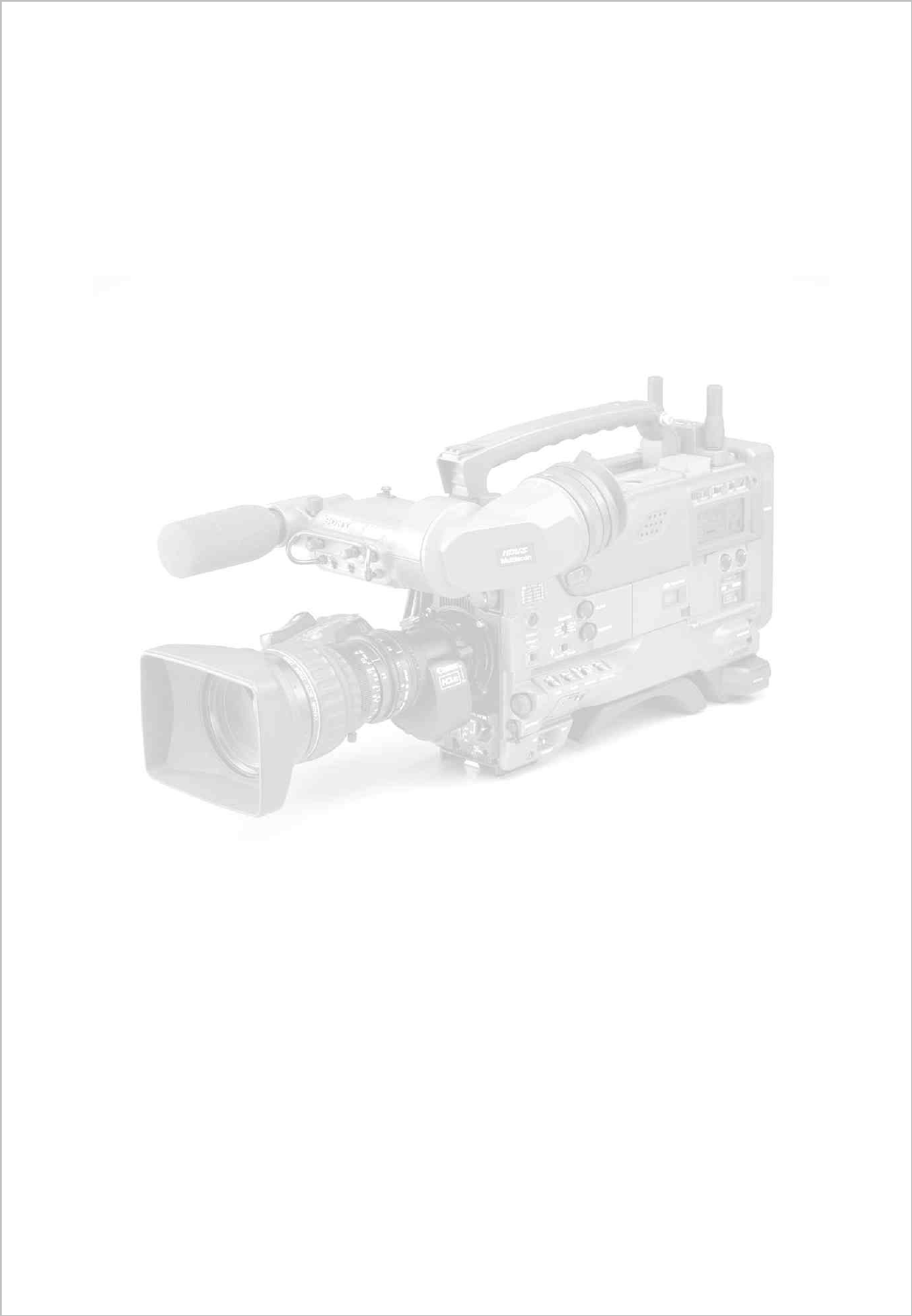
The HDW-750P is a high definition camcorder recording to the HDCAM
format. It can operate in either 25P progressive scan mode, or 50i
interlaced. It’s designed for the European HD for TV market, but has found
many other applications, from corporate to commercials and movies.
The HDW-730S can operate
at either 50i or 59.94i and is designed mainly
for TV applications for the European or American / Japanese / 60Hz
market.
This guide is designed for people using the Sony HDW-750P or
HDW-730S camcorder who need some practical advice when
preparing fo
r a shoot. It’s pitched at a level that will make most
sense to people coming from a Digital Betacam
background,
but will hopefully still be of use to those coming from film or
other formats.
2
As usual with these guides, the general philosophy is to record as much information as cleanly as
possible to the tape. There are many ways you can change the look of your pictures in camera, but
unless you’re sure you’re going to get exactly the final effect you want, then you’re probably better
spending time on lighting and composition. There are some important settings you need to get right,
but after that, the ‘750 probably needs less ‘fine tuning’ than equivalent standard def. cameras.
1. Quick Start
2. Differences between the 7590P and 730S
3.
Files and Menus
3.1 Menus
3.2 Files
3.3 Layers
3.4 File Structure
3.5 Loading Files
4. Camera matching
5. Frame Rate
6. Shutter
7. Gain
8. Outputs and monitoring
9. Options
10. Audio
11. Filters
12. Detail
13. Matrix and gamma
14. Lenses
15. Back focus
16. Viewfinders
17. Menu list
If you’re asked to use the ‘750 or ‘730S at short notice, and don’t have the luxury of preparation time,
here’s a very short list of things to check to get you in the right ball park for getting sensible pictures:
• If you have a memory stick you wish to use: load an all file.
The all file overwrites all previous settings in the camera with your preferred settings.
• If you don’t have a memory stick, go to the file menus and set user file, reference file and
all file to ‘ALL PRESET’
This is effectively a factory reset.
• If you’re putting everything to all preset, after doing so, you may wish to turn on the preset
matrix and set it to matrix 2 (ITU-709). You should turn the detail level down to about –30.
These two adjustments will get you from the factory preset condition which is a little de-
saturated and over detail corrected, to a useful general purpose shooting condition.
• Choose a frame rate.
• Set the shutter to 50Hz if shooting at 25P.
All these operations are covered in more detail in the following sections.

3
!
!!
!
"
"
#
#
In most respects the two camcorders are identical. The following are the important differences:
HDW-750P HDW-730S
25P or 50i 50i or 59.94i
2x optical filter wheels 1 x optical filter wheel
FIT CCDs IT CCDs
Concealed accessory connector at rear No connector
$%&
The explanation in the manuals of how the files and menus work is a little confusing to say the least.
This is an attempt to clarify what happens and when.
• There are menus, which allow you to access and adjust a parameter.
• The values for each parameter are stored in files.
• There can be a value stored for a parameter in each of several layers of information.
• The end result can be the sum of the data values in several layers (Relative Data)
• The end result can be the value of just the top layer of data. (Absolute data)
The terminology used in the manuals is possibly the most confusing aspect. For instance the word
‘USER’ is applied to menus, layers and files…user menu; user file; user layer. The difference
between these three terms is important.
&
The access point to groups of adjustable items.
• User Menu
Normally accessible whenever the camera is switched on. Stuff from any of the menus below
can be added to this menu, so that it could become the only menu you need. You can’t really say
what the user menu does, as it depends how many items and pages from the rest of the menu
are allocated to it.
• Top menu
This is the menu of menus…Normally when you turn the menu on, you get the user menu as
described above. If you turn the menu on whilst holding the front scroll button pressed in, you get
the following extra menus to pass the time with in airport departure lounges:
• User Customize
This is where you go to customize the user menu described above. Here you can add and delete
items to the user menu. You can create 5 pages of 10 items chosen from the menus below, plus
any whole pages you like, to create your user menu.
• All menu
72 pages of settings. As the name suggests it contains all the available pages. These 72 pages
are then split into more manageable chunks, comprising the operation, paint, maintenance, file
and diagnostic menus described below.
• Operation Menu
Things that affect the way switches, outputs and displays are configured. Not items that directly
affect pictures, but affect the way the controls work.
4
• Paint Menu
Picture control. ‘The look’. Detail, Gamma, Knee etc. are all adjusted in this menu. Also has
access to scene files to store and recall different ‘looks’.
• Maintenance Menu
Format switching (25P/50i ) is here, plus more obscure technical stuff. Includes the things that
used to be in the menu accessed via the button on the timecode panel on digital betacam
camcorders.
• File Menu
Save, load, store and recall all the different file types. (You can also access some files from
within each individual menu. For instance you can load a lens file from within the operation
menu, or from within the file menu…it’s the same result.)
• Diagnostics
In the unlikely event of a problem! This menu can help isolate a fault to a particular board. Also
tells you software versions of the various boards in the camera, and drum running and operation
hours.
• (Service Menu)
Not normally accessible. You need to set internal switches to gain access to this menu.
$%'
Stored information about groups of adjustable items
• User
Holds whatever values have been allocated to the user menu.
• User Preset
The user file can be stored as a default setting, by moving it from the user layer to the preset
layer. See layers below.
• Scene
Mostly items from the paint menu. Use this as a sort of ‘scratchpad’ for holding picture set-ups.
• Reference
Stored separately to the other files, this is only accessed during an ‘auto level’ operation. Auto
level is a function normally associated with systems cameras, and is only accessible from RCPs
designed for this kind of work, so is not really relevant to the ‘750. During auto level the camera
reads the reference file, and copies the items held in it to the preset layer of the camera.
• All
Overwrites all the user and preset layers, except for items held in the lens file. This is the one to
use for matching cameras.
• Lens
Shading, flare and colourimetry info specific to the lens or camera.
( ) '
Where the files are stored
• User
This layer is added to the preset, service and factory layers to produce the final output of the
camera. Any values you tweak via the menu are changed in this layer, and if you recall a file you
will see the results here.
5
• Preset
A default setting where you can decide what the default should be. When you hit the STD button
on an RCP, or ALL PRESET in the menus, you are deleting various values held in the user
layer, leaving the camera at its preset value. Use STORE USER PRESET or STORE ALL
PRESET to change the default settings.
• Service
Think of this as the factory reset level (though factory level is actually another layer down). If you
clear the user and the preset layers, this is where you end up, as the camera came out of the
box. (This is done using CLEAR ALL PRESET in the ALL FILE page of the file menu.)
• Factory
What it says.
•
Memory Stick
You can store 100 user files, 100 scene files, 100 all files, 100 lens files and a reference file on a
memory stick. That’s probably enough.
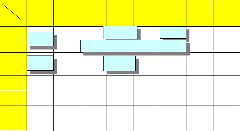
*$%
*$%*$%
*$%
MENUS
LAYERS
USER
USER
CUSTOM
OPS
PAINT
MAINT
FILE
SERVICE
DIAG.
USER
PRESET
.
SERVICE
FACTORY
MEM.
STICK
User files
x100 Scene
files x100 Lens files
x100
All files
x100
Ref file x1
Best not to use the reference file. You can delete it using REFERENCE CLEAR, though loading an
ALL file will overwrite all the values created from it. (The reference file itself is not overwritten.)
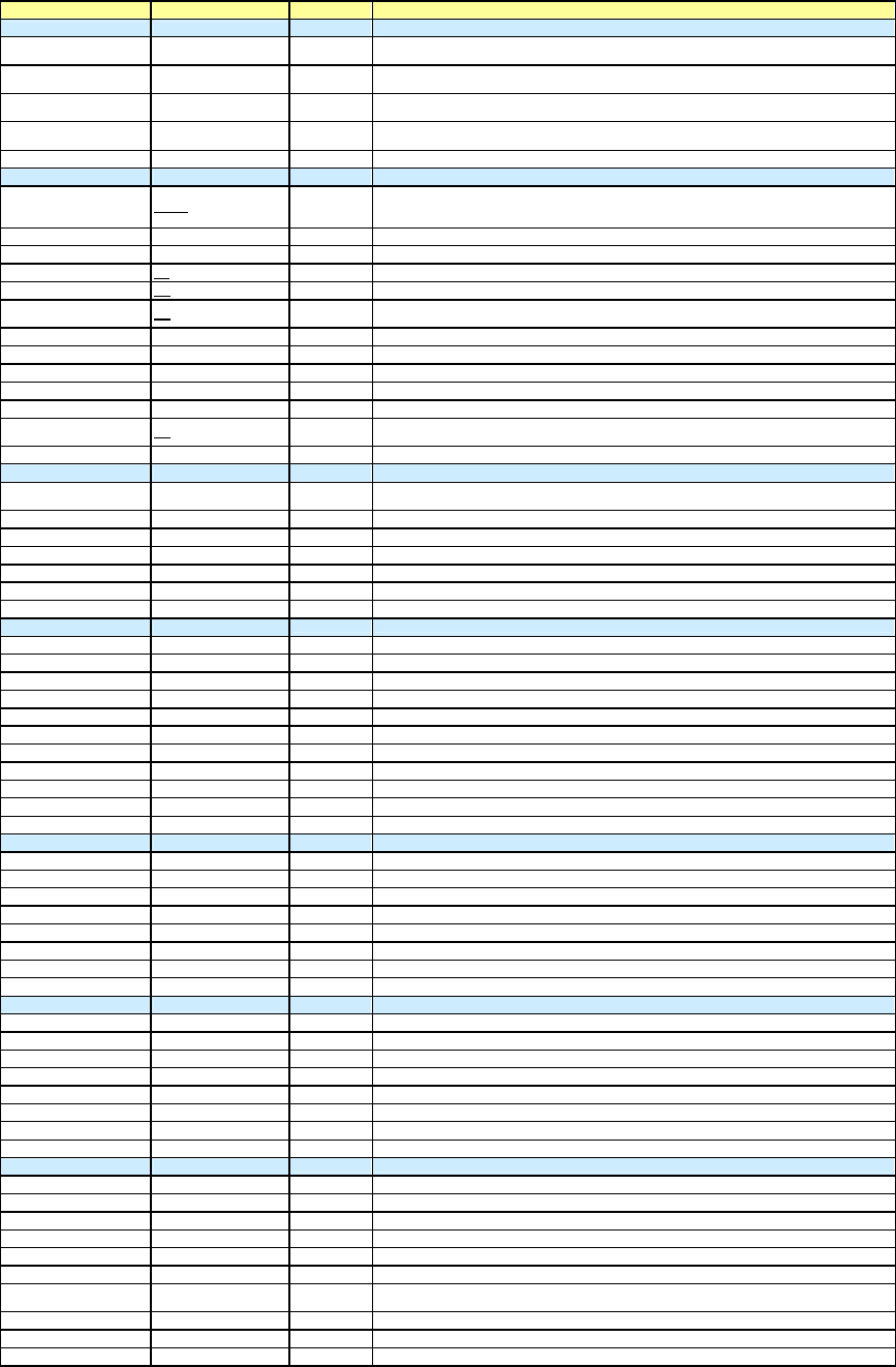
Lens File
x5
User File
Scene File
x5
Preset
User
File
All File
Reference
File
6
( + $%
( + $%( + $%
( + $%
Load and save operations relate to file transfer to and from memory stick.
Store and recall relate to file transfer within the camera.
If you have a memory stick with setups already stored on it:
Open the side panel and insert the memory stick. The red LED will light if the memory stick is
recognised.
No files are loaded until you go to the menus and tell the camera to load a file.
Press the front rotary control in, and keep it pressed while you use the toggle switch on the side of
the camera to turn the menu on.
You should now see the ‘TOP MENU’ displayed in the viewfinder.
Turn the rotary control, and select the ‘FILE MENU’
Turn the rotary control and select the ‘USER FILE’ page.
If you have a ‘USER’ file stored on your memory stick, this is probably the best one to load first.
• If you’ve customized the user meu it will now contain the pages you need to use, so you don’t
need to find the ‘TOP MENU’ and navigate through to the page you need.
• It will set up the camera monitoring outputs the way you want and display the menus on the
downconverted composite output if required.
• It will set up the viewfinder displays the way you like to see them.
• It will configure the buttons and switches the way you like to use them.
Select ‘USER FILE LOAD’ and choose the file you wish to use. If you don’t have a file stored, select
‘USER PRESET’, which returns the user menu to the factory preset settings.
Turn the rotary control and select the ‘ALL FILE’ page.
Loading an ‘ALL’ file is like wiping the slate clean before using a camera. All settings that will affect
the way your pictures look will be overwritten, and you can be sure of starting from a known point. If
you haven’t created an ‘ALL’ file, then you can select the factory preset file.
Select ‘LOAD ALL FILE’
If you have a suitable file on the memory stick, select and load it.
If you don’t have a memory stick, and you want to clear any existing set up from the camera:
From the ‘ALL FILE’ page, select ‘ALL PRESET’
This is the equivalent of hitting the factory reset button.
Finally, go to the ‘SCENE FILE’ page, and confirm that none of the check boxes next to the scene
files have been selected. (Click on the scene file to de-select.)
Think of the ‘ALL’ file as the base level for the camcorder that you wish to start from for a particular
shoot.
If you have some scene files stored on your memory stick, load them as well, but it’s not essential.
Use the scene files to store adjustments and tweaks to that initial setup.
If the camera already has some scene files left in it, labelled ‘Oscar Winning Cinematographer V1.0’
or similar, it’s probably best to ignore or overwrite them. Even if they were your files originally, they
could have been modified and re-saved.
Check the camcorder is set to the correct frame rate.
Frame rate cannot be selected by loading files, as changing frame rate requires power down and
power up. You can however store the frame rate you wish to use in a file, and you will get a prompt
to change the frame rate during the file load process if it’s not set to the one associated with the file.
If you’re shooting at 25P, set the shutter to 50Hz
7
*,& -+
Use the same ‘ALL’ file for all cameras on a multi-camera shoot.
Easiest method of keeping things colour matched is to use preset white balance and the same filter
on all cameras. (Unless of course colour temperature changes during the shoot, and you want the
white balance to stay the same.)
Ideally, all cameras should be checked against a reference camera, on the bench before the shoot
begins (yes,yes…I know). If there is any small difference in preset colour temperature, it can then be
offset electronically or VA gains can be tweaked to match.
When genlocking cameras, the ‘750 and ‘730 will read SD sync pulses in order to lock to timecode. If
doing a live HD mix, then tri-level sync must be used.
$
$
,
,
.
.
The HDCAM format allows for many different frame rates. With the HDW-750P, things are a little
simpler, as you can record at either 25P or 50i. Put very crudely, you’ve got film mode and video
mode.
25P will give you similar motion artefacts (flicker and blur ) to film acquisition (see also the next
section on use of the shutter.)
In 50i mode you will have the same motion artefacts as with Digital Betacam, but at a much higher
resolution of course.
Shooting at 25P doesn’t mean you’re excluded from the 24P world of theatre projection and
international distribution. 25P originated material can be played back 4% slow at 24P, in a kind of
inverse way to a 24fps movie going through a telecine at 25fps.
The ‘730S also offers two frame rates: 50i and 59.94i
There’s no progressive scan mode, so if you’re looking for a filmic look, ideally you’d use the 750P,
or F900. That’s not to say you couldn’t use the film effect process on 50i pictures from the 730S, in a
similar way to digi-beta….but with 1080 line source material you’ll get a much better result than you
would with digi-beta.
The 730s has a useful advantage if working for productions coming from the NTSC world, as it can
work at 59.94i (people often think of NTSC as 60Hz, but it’s actually 59.94Hz)
Most HD VTRs can be set to play back at a wide range of different speeds. If for instance you’ve
shot at 25P and you’re scanning back to 24fps film, your programme duration will be 4% longer, and
audio will be pitch shifted half a semitone down (though it can be electronically shifted back again
and re-layed if necessary).
/
/
-
-
Use of shutter on an HD camcorder is a little different to Digi Beta. The progressive scan mode (25P)
that is the most popular mode of operation on the HDW-750, really needs to be used with the
electronic shutter switched on. (Unlike Digi Beta, where it is rarely used).
In 25P mode, the camera takes 25 pictures per second (similar to a film camera) each one exposed
for 1/25
th
of a second. This is quite a long exposure, and results in a significant blurring of moving
images. If you use the shutter to expose for only half this period (i.e. 1/50
th
of a second) you get a
more acceptable compromise between blur (no shutter) and flicker (fast shutter). This isn’t really very
surprising, as you are acquiring images in the same way as a film camera normally would, with a 180
degree mechanical shutter.
As a general rule, a shutter speed twice that of the frame rate is equivalent to a 180 degree film
camera shutter and gives good results. You can still tweak the ‘angle ‘ of your shutter if required, e.g.
to eliminate flicker from 60Hz lighting, use a 60Hz shutter; or to eliminate flicker from a computer
CRT monitor, use the clearscan facility.

8
At a frame rate of: A film shutter angle of: Is equivalent to:
24 fps 200 degrees 43.2 Hz
24 180 48
24 172.8 50
24 144 60
24 120 72
25 200 45
25 180 50
25 150 60
25 120 75
With software version 1.7 and above it is possible to change the display of shutter speed to angular
notation.
This can be done from the service menu (see your dealer for to get this feature enabled for you.)
7.0
The gain selections available from the switch on the side of the camcorder can be programmed in
the user menu just like other camcorders.
A further option, available via the service menu, is to have the gain level displayed as an ISO / ASA
sensitivity rating. Useful if you’re from a film background, but this feature should be used with care,
as the displayed ‘speed’ of the camera does not take into account other factors affecting sensitivity:
• Shutter
• ND filters
• Range extender
• Transmission factor of the lens
These should all be added into the equation before attempting to expose pictures purely by using a
light meter and the ASA rating of the camera.
0
0
1
1
1
1
*
**
*
/
/
2
22
2
/
/
3
3
2
2
2
2
Note that if you’re shooting at 25P you will probably choose to use a 50Hz shutter, and should
therefore rate the cameras speed at half the above figures,
9
24 5 & +
HD will not fit into a PAL monitor. Too many lines, too high line frequency. This can make things a
little awkward for location monitoring and viewing.
The HDW-750P / 730S however,comes with a number of standard and optional output signals that
should give you what you need.
Firstly there’s an HDSDI output. HDSDI is a similar idea to the SDI signal that is the de-facto digital
interchange for standard definition. It just sends a lot more bits per second. (1500 Mbps as opposed
to 270Mbps for SDSDI.) Unfortunately we’re going to have to get used to the fact that there are now
two flavours of SDI, and they don’t mix.
Use the HDSDI output to connect to an HD monitor with an HDSDI input card. This is the signal you
should use for critical picture monitoring, or to send to a separate HD VTR or disk recorder for a
parallel recording or copying.
HDSDI is a very high frequency signal, so it doesn’t go very far down an ordinary BNC cable…about
40m maximum.
The test out BNC supplies an analog luminance (Y) HD signal that can be fed to an HD monitor with
a component input. It will only show a monochrome picture, as it’s only luminance, with no colour
components, but you can use it to check framing or view menus.
However…most camcorders are fitted with a down-converter option, that gives you several SD
monitoring options.
How do you tell if the down-converter option is fitted?
• There will be an extra BNC connector fitted in a ‘bulge’ in the bottom right hand corner of the
side of the camcorder, pointing out of the back next to the 12V DC XLR connector.
From this connector you will be able to get either of the following, as chosen from the user menu:
• Composite PAL signal, that can be fed to any SD monitor with a composite input,
• SD SDI signal for good quality SD monitoring, or perhaps a Digi Beta
At the same time the test output can also now supply a composite video signal, so you could have
for example:
• Composite video from the test output feeding floor monitors.
• SDI from the down-converter output feeding a digi beta or DVCAM offline VTR
• HDSDI feeding an HD directors monitor.
10
34 -4 5
These are the optional boards that can be fitted internally to the HDW-750P or 730S:
• HKDW-702 Down-converter for SD SDI or VBS outputs.
• HKDW-703 Cache recording for time-lapse or loop recording.
• HKDW-704 GPS support (TBA)
• HKDW-705 Slow shutter option. Up to 64 frame exposure times.
You can check which options are installed on the final page of the diagnostic menu.
1
Similar to Digital Betacam, but here are some points to bear in mind:
• The supplied front mic. is stereo, and uses a 5 pin XLR connection to the camera body.
• The optional internal radio mic. option is the WRR-855 model, as used previously on SX and
IMX camcorders. It’s a single channel diversity unit.
• There’s an extra 3.5mm monitoring jack connection at the front of the camcorder.
• All those difficult to access menu items that you used to have to get to via the timecode
panel on Digi Beta are now in the main camera menus, in the maintenance section.
• If you are using the HDVF-C30W colour viewfinder, there is no attachment point for the front
mic. (You can use mic. mounting bracket CAC-12 )
$%
As this camera provides such a lot of natural resolution, and you’ve probably paid a lot of money for
an HD lens, it seems kind of perverse to put softening filters in front of the lens unless there’s a
particular dramatic effect you’re after. Otherwise internal filters are the same as Digital betacam.
Alternative internal filters can be provided by Tiffen or Calmar. Contact your dealer to have them
fitted.
The 750P has a dual filter wheel, the 730S having a single wheel with a mix of colour correction and
ND filters.
%
As mentioned above, there’s a lot of natural detail available, and even with the detail switched off
entirely, you’ll still get very good pictures. The camcorder is often used in this mode, particularly if
there will be a final print to film. Leaving a small amount of detail correction in will not cause any
visible ringing or overshoots on edges.
Some things to be aware of:
• The HDW-F900 and the ‘HDW-750P / 730s are very different in the way the detail works.
There’s much less range available on the F900, and if you wind the detail up to the end stop,
it still won’t make the pictures very hard edged or unpleasant.
• The ‘750 / 730 is different. If you wind the detail right up you can get very hard edged
pictures indeed.
• Beware of winding detail level down too far. Below about –50 it will start to apply negative
detail, and artificially soften edges. (i.e. softer than just turning detail off.)

11
& 6 + ,,
• Key to the matrix and gamma curve numbers used in the paint menu:
o EBU matrix is recommended, or ITU-709 preferred by BBC R&D.
o Matrix off will give an acceptable but desaturated look.
o Standard Gamma curve 4 has a high initial gain, and is useful if going through a grading
process during post production.
Matrix Std. Gamma Film Gamma
1 SMPTE-240M Digi Beta (3x) 5248
2 ITU-709 MPTE 240M (4x) 5245
3 SMPTE Wide ITU 709 (4.5x) 5293
4 NTSC BBC (5x) 5296
5 EBU
6 ITU-609
* (
The lens mount is the standard 2/3” bayonet mount, and all the main manufacturers provide a range
of HD lenses, in film style and EFP variants, plus several sets of primes. You can of course use SD
lenses on HD cameras, and they’ll function perfectly well. It does seem a bit like buying a very
expensive hi-fi system and using some cheap speakers though.
0!
There is no particular problem with back focus on the ‘750 / 730, or the ‘F900. It’s a slightly more
precise adjustment, because of the smaller circle of confusion of HD, but the principle is the same as
SD.
/ #!
There are three options available:
• HDVF-20W Monochrome tube monocular. (Flicker / blur in progressive mode can be
exaggerated in the viewfinder.)
• HDVF-C30W Colour LCD monocular (Needs version 1.70+ AT and SS software. No
mounting point for front mic.)
• HDVF-C750 Colour LCD 6.5” (Useful sidemount bracket which attaches to VCT-14
tripod plate is available from Dowling Design: http://ddesign.co.uk/)
& (
A complete list of menu items is attached. The ops manual and volume 1 of the maintenance guide
will tell you what each item does, but you may find the list useful to note down your preferred
settings.
A suggestion is offered where something other than the factory preset will give good results.
Values in square brackets [ ] are suggestions that will give a set up appropriate for film transfer when
using the pre-knee ‘fix’ option in the DCC page of the maintenance menu, which is available with
software V2.0 onwards
%,
Whilst every effort has been made to ensure the accuracy of this document, no responsibility can be accepted
for consequential loss resulting from any error contained in it. Software versions change regularly. Please check
that your pictures look the way you want them to on a properly set up monitor when entering new settings.
12
OPERATION MENU
01 OUTPUT SELECT
HD SDI OUT on/off Highest quality output for critical monitoring, or recording to external device. Max cable run approx
60m. Uses power, so turn off if you need to conserve batteries.
REAR BNC OUT VBS/SDI/off Composite video (VBS) or SDI selectable from this output, as long as the downconverter option is
installed.
TEST OUT SELECT HD/SD Test output can deliver composite with menus superimposed, if downconverter installed, or one of
the HD components if HD selected. (Y, R-Y or B-Y)
DOWN CON MODE SQEZE /LETTR/CROP SQEZE The downconverter will also do aspect ratio conversion, and crop or letterbox the SD signal for you.
SQEZE is just standard 16:9.
02 FUNCTION 1
ASSIGN SW 1 EZ-FC
Lens Ret Various functions can be assigned to the button and switch on the side of the camera.
Front mic on/off: Loop record: test out chc: Vf markers: easy focus: Re-take: ATW: Return video:
Lens RET: Record: Turbo gain: Telemark: Zebra.
ASSIGN SW 2 F.Mic VF markers Front mic on/off: Loop record: test out chc: Vf markers: Zebra
FRONT MIC SEL Mono/stereo
DF/NDF DF NDF Drop frame mode for NTSC timecode sync.
END SEARCH Off
LOOP/INTVL REC Off
The loop recording and interval recording (timelapse) features are only enabled if the memory cache
option is installed.
LOOP REC TIME 1 - 8 secs (0) You can choose to start recording what happened up t
o 8 seconds ago when you hit the REC button
TAKE TOTAL TIME 5min When using timelapse mode, set the total real time duration of the event to be captured here.
REC TIME 5sec Set the duration of the event once ‘timelapsed’ here.
NUMBER OF FRAME 1 If in manual timelapse mode, you can set the number of frames to be recorded at each interval here.
TRIGGER INTERVAL 5 MIN If in manual timelapse mode, set the interval between frame captures here.
PRE LIGHTING Off In timelapse mode, the camera can turn on the power to the anton bauer light connector a set
interval before the frame is grabbed.
03 FUNCTION 2
WHITE SW B Mem/ATW The memory B position of the white balance switch can be re-
configured to be the auto tracing white
balance switch. (or you could allocate ATW to am assignable button.)
SHOCKLESS WHITE Off/1/2/3 3 You can set a ‘soft’ transition from white balance mem. A to mem. B
ATW SPEED 4 The speed of the above transition is set here.
LOW LIGHT Off/on Turn off that annoying warning message…
LOW LIGHT LEVEL -99 to 99 (0) ….or set the level at which it appears.
BATTERY WARNING 10% - 20% Sets the amount of battery warning for Anton Bauer batteries.
04 VF DISPLAY 1
VF DISPLAY On/off
DISPLAY MODE 1/2/3 Mode 3 shows all warnings, and switch changes in VF, mode 2 shows some, mode 1 shows none.
EXTENDER On/off Following items determine how much information is displayed in your viewfinder:
FILTER On/off Displays which optical filters selected.
WHITE On/off Off Displays white bal. A/B/Preset
GAIN On/off Off Displays gain selected
SHUTTER On/off Useful to turn this one ‘on’ if in progressive scan, to remind you to use shutter.
AUDIO On/off Off Displays audio level meters
TAPE On/off Off Tape remaining time
IRIS On/off Displays F stop
05 VF DISPLAY 2
ZOOM On/off Off Numerical display of zoom position. Useful for reframing shots
COLOUR TEMP On/off White balance info.
VOLT On/off Battery voltage
DC IN On/off DC power input
WRR RF LEVEL On/off If you have the internal radio mic fitted, this will give you a signal strength reading in the viewfinder.
TIMECODE On/off TC in viewfinder, and on test out if characters enabled on test output.
GPS On/off Future option
06 ! LED
GAIN On/off There’s a warning ! marker that will appear in the viewfinder according to the way this page is set.
SHUTTER On/off Off If you set an item to ‘on’ , then the ! will appear if that function is
WHITE PRESET On/off Off
ATW RUN On/off
EXTENDER On/off
FILTER On/off Off
OVERRIDE On/off
07 MARKER 1
MARKER On/off
CENTRE On/off
CENTRE MARK 1 to 4 (3)
SAFETY ZONE On/off
SAFETY AREA 80 /90 /92.5 / 95 %
ASPECT On/off
ASPECT SELECT 14:9, 13:9, 4:3, Vista,
Scope
ASPECT MASK On/off Turns on / off the ‘greyed out’ side panels outside the aspect ratio mask selected .
ASPECT MASK LVL 0 to 8 Sets the degree to which areas outside the aspect markers are greyed out
100% MARKER On/off

13
08 MARKER 2
USER BOX On / Off You can draw a box cursor in the viewfinder, any size and position.
USER BOX WIDTH 240
USER BOX HEIGHT 135
USER BOX H POS 0
USER BOX V POS 0
CENTER H POS
CENTER V POS
ASPECT SAFE ZONE Turns ON/OFF the SAFETY ZONE MARKER display with respect to the ASPECT MARKER.
ASPECT SAFE AREA Selects the ranges of the SAFETY ZONE MARKER display with respect to the ASPECT MARKER.
09 GAIN SW
LOW -3 to 42dB (0) [-3dB] Generally leave at ‘0’. Dynamic range slightly reduced at –3dB.
MID -3 to 42dB (6)
HIGH -3 to 42dB (12)
TURBO -3 to 42dB (42) -3dB Unlikely to use 42dB…you could set this switch to –3dB.
TURBO SW IND On/off
10 VF SETTING
ZEBRA On/off Only use if you have a viewfinder without a front on/off switch
ZEBRA SELECT Zebra 1, 2 or BOTH Usually set zebra 1 at 70% and 2 at 95%. Gets a bit busy if you use both. Don’t try and rationalize
the numbers below. We know it should be a direct % equivalent, but it isn’t. Sorry. Maybe future
software version will sort it out.
ZEBRA1 DET LVL 1 to 100% (0) 0=70% -15=65%, 0=70%, +19=75%, +90=95%, +110=100% (subject to small variations between cameras)
ZEBRA2 DET LVL 1 to 100% (0) 0=98% -72=90%, -25=95%, 0=98%, +20=100%
ASPECT Off
VF DETAIL LVL -99 to 99 (0)
VF DETAIL H LVL -99 to 99 (0)
VF DETAIL V LVL -99 to 99 (0)
11 AUTO IRIS
OVERRIDE Off
SPEED 2
CLIP HIGH LIGHT Off
WINDOW 1
WINDOW IND Off
VARIABLE WIDTH 240
VARIABLE HEIGHT 135
H POS 0
V POS 0
12 SHOT ID
ID-1
Four different sets of characters can be saved here, any one of which can be selected to be
ID-2
recorded in meta-data. Selection of which ID you want to use is via the next page.
ID-3
ID-4
13 SHOT DISP
DATE On/off On
TIME MODEL On/off On
MODEL NAME On/off On
SERIAL NO. On/off On
ID SELECT On/off
SHOT BLINK CHCTR
14 SET STATUS
STATUS ABNORML On/off Pushing up the toggle switch on the side of the camera pages through a number of status display
STATUS FUNC. On/off pages. [useful for checking frame rate or audio inputs]. You can delete some of these pages if you
STATUS AUDIO On/off don’t find them useful.
STATUS GPS
15 TEST OUT
MARKERS On/off On Sets what you see out of the ‘TEST’ BNC connector on the side of the camera.
VF DISPLAYS On/off On
MENUS On/off On
ZEBRA On/off
OUTPUT SELECT Y/R/G/B
16 OFFSET WHT
OFFSET WHITE A On/off You can tell the auto white balance to always add an offset to its result.
WARM / COOL A Kelvin reading (3200) A bit like putting a ¼ blue gel in front of the camera and then removing it after white balancing.
COLOUR FINE A -99 to 99 (0)
OFFSET WHITE B Off/on
WARM / COOL B Kelvin reading (3200)
COLOUR FINE B -99 to 99 (0)

14
17 SHUTTER ENABLE
ECS On/off Electronic clear-scan. Continuously variable shutter used for example to eliminate flicker from CRT
computer monitors
1/33 On/off You can eliminate any shutter speed options you never use.
1/50 On/off (Saves time when selecting a shutter speed with the toggle switch on the front of the camera.)
1/60 On/off
1/125 On/off
1/250 On/off
1/500 1/1000 On/off
18 LENS FILE
LENS FILE SELECT 1
F. ID
F. STOP 1.7
19 UMID SET
EX OWNERSHIP REC Unique material Identification information. Recorded in meta data to uniquely identify all recordings.
COUNTRY CODE
ORGANIZATION CODE
USER CODE
INSTANCE NO.
TIME ZONE
MACHINE
20 GPS SETUP
GPS There is a GPS option for these camcorders that will record location of all recordings in meta data.
GPS RELOAD(MS)
GPS TRACE
TRACE INTERVAL
TIME ZONE
GPS DATUM
GPS 8 PIN FORMAT
PAINT MENU
01 SW STATUS
GAMMA Off/on Switch various functions on and off. Generally leave them as factory set,
BLACK GAMMA Off/on
MATRIX Off/on …. except for matrix, which is usually switched on. See main matrix page in paint menu.
KNEE Off/on
WHITE CLIP Off/on
DETAIL Off/on
APERTURE Off/on
FLARE Off/on
EVS Off/on
TEST SAW Off/on
02 WHITE
COLOUR TEMP A Temperature (3200) Tells you the colour temperature of the white balances stored in memories A and B
COLOUR FINE A -99 to 99 (0) You can manually adjust these values on this page.
R GAIN A -99 to 99 (0)
B GAIN A -99 to 99 (0)
COLOUR TEMP B Temperature (3200)
COLOUR FINE B -99 to 99 (0)
R GAIN B -99 to 99 (0)
B GAIN B -99 to 99 (0)
03 BLACK
MASTER BLACK -99 to 99 (0) [-1] Master black lifts or darkens low luminance areas of the picture. Also known as pedestal.
R BLACK -99 to 99 (0) Individual colour blacks change the colour balance in low luminance areas.
B BLACK -99 to 99 (0)
MASTER FLARE -99 to 99 (0)
R FLARE -99 to 99 (0)
G FLARE -99 to 99 (0)
B FLARE -99 to 99 (0)
FLARE Off/on
OUTPUT SELECT Y/R/G/B
04 GAMMA
GAMMA Off/on
MASTER GAMMA -99 to 99 (0) Master gamma lifts or darkens mid luminance areas of the picture.
R GAMMA -99 to 99 (0) Individual colour gammas change the colour balance in mid luminance areas.
G GAMMA -99 to 99 (0)
B GAMMA -99 to 99 (0)
OUTPUT SELECT Y/R/G/B Engineering control for looking at individual channels during lineup.
GAM SELECT STD STD/FILM [2] 3 1 Digi Beta (3x), 2 SMPTE 240M (4x), 3 ITU 709 (4.5x), 4 BBC (5x)
GAM SELECT FILM 1 to 4 (3) 3 1 5248 2 5245 3 5293 4 5296

15
05 BLK GAMMA
BLACK GAMMA Off/On [on] Black gamma changes the initial slope of the gamma curve , only in the blacks.
BLK GAMMA RANGE Low/l.mid/h.mid/high [High]
MASTER BLK GAMMA -99 to 99 (0) [22]
R BLK GAMMA -99 to 99 (0)
G BLK GAMMA -99 to 99 (0)
B BLK GAMMA -99 to 99 (0)
OUTPUT SELECT Y/R/G/B
06 KNEE
KNEE Off/on Usually leave the knee switched on.
KNEE POINT 50 to 109 (95) [50] 90 Sets where, as a percentage of the luminance scale, the knee starts to act.
KNEE SLOPE -99 to 99 (0) [-136] -10 Sets how much compression is applied by the knee circuit.
KNEE SAT. Off/on [on] Increases colour saturation in picture areas compressed by the knee, in proportion for RGB
KNEE SAT LEVEL -99 to 99 (0) [70]
WHITE CLIP Off/on
WHITE CLIP LEVEL 100.0 to 109.5 (105) [109.5] Normally set to about 104 for BBC / ITV preferred levels.
07 DETAIL 1
DETAIL Off/on
APERTURE Off/on
DETAIL LVL -99 to 99 (0) -20 Factory setting of ‘0’ is a bit harsh. Normally turn down to between –20 and -30
APERTURE LVL 0 to 15 (0) (don’t turn detail level below –70…it starts to look artificially soft.)
H/V RATIO -99 to 99 (0)
CRISPENING -99 to 99 (0)
LEVEL DEP Off/on
LEVEL DEP LVL -99 to 99 (0)
DETAIL FREQ -99 to 99 (0)
08 DETAIL 2
KNEE APERTURE Off Knee aperture adds detail edges only to highlight areas compressed by the knee circuit.
KNEE APT LVL 0
DETAIL WHITE LIMIT 0 [-175] Limits positive going (white halo) detail overshoots
DETAIL BLACK LIMIT 0 [-142] Limits negative going detail overshoots
DETAIL V-BLK LIMIT 0 [34]
09 SD DETAIL
SD DETAIL Off/on There is a separate detail circuit for the down-converted SD output. Doesn’t affect recorded pictures.
SD DETAIL LVL -99 to 99 (0) -10
SD CRISPENING -99 to 99 (0)
SD DETAIL WHITE LIMIT 0 to 15 (0)
SD DETAIL BLACK LIMIT -99 to 99 (0)
SD LEVEL DEP -99 to 99 (0)
SD LEVEL DEP LVL Off/on
SD DETAIL FREQ -99 to 99 (0) +50
SD H/V RATIO -99 to 99 (0)
10 SKIN DETAIL
SKIN DETAIL ALL Off Skin detail can key out a particular colour tone and reduce detail levels in that area.
SKIN DETECT Position the on screen marker over the colour to be corrected and select the auto detect function.
SKIN AREA IND Off Displays a zebra type pattern over the areas selected for correction.
SKIN DTL SELECT 1 3 different settings can be remembered.
SKIN DETAIL On
SKIN DTL LVL 0 Set the amount of detail to be removed (or added) here.
SKIN DTL SAT 0 Manually select the colour saturation to be targeted.
SKIN DTL HUE 0 Manually select the colour hue to be targeted.
SKIN DTL WIDTH 40 Manually select the width of the range of colours to be targeted.
11 LINEAR MATRIX
MATRIX Off/on
MATRIX ( USER) Off/on [On]
MATRIX (PRESET) Off/on [Off] On
MATRIX ( PRST SEL) 1-2-3-4-5-6 2 1 SMPTE-240M, 2 ITU-709, 3 SMPTE Wide, 4 NTSC ,5 EBU, 6 ITU-609
MATRIX ( USER) R-G -99 to 99 (0) [-53]
MATRIX ( USER) R-B -99 to 99 (0) [0]
MATRIX ( USER) G-R -99 to 99 (0) [-5]
MATRIX ( USER) G-B -99 to 99 (0) [-6]
MATRIX ( USER) B-R -99 to 99 (0) [-1]
MATRIX ( USER) B-G -99 to 99 (0) [-9]
12 MULTI MATRIX
MATRIX Off/on .
MULTI MATRIX Off/on The multi-matrix can pick up on a particular colour in a scene and change its hue and saturation
AREA IND Off/on A zebra type pattern can be superimposed on targeted areas of colour
COLOUR DETECT
AXIS B/B+/MG-/MG/ MG+/R/R+/YL-YL/YL+/G-/G/ /G+/CY/CY+/B-
HUE -99 to 99 (0)
SATURATION -99 to 99 (0)

16
13 V MOD
VMOD Off/on
MASTER VMOD -99 to 99 (0)
R VMOD -99 to 99 (0)
G VMOD -99 to 99 (0)
B VMOD -99 to 99 (0)
OUTPUT SELCT Y/R/G/B
14 LOW KEY SAT
LOW KEY SAT Off/on Used to increase colour saturation in low luminance areas of picture.
LEVEL -99 to 99 (0) Use with care, as effect on one scene may not look good for a different scene.
RANGE Low/l.mid/h.mid/high LOW : 0 to 3.6 % L.MID : 0 to 7.2 % H.MID : 0 to 14.4% HIGH : 0 to 28.8 %
Y BLK GAMMA Off/on [On]
Y BLK GAMMA LVL -99 to 99 (0) [31]
Y BLK GAMMA RANGE Low/l.mid/h.mid/high [H.Mid]
15 SCENE FILE
1 TO 5 This is the same scene file page that can also be accessed from the FILE menu.
STANDARD
SCENE RECALL
SCENE STORE
FILE ID
MAINTENANCE MENU
01 WHT SHADING
SHADING CH SELECT R/G/B
OUTPUT SELECT Y/R/G/B
RGB WHITE H SAW -99 to 99
RGB WHITE H PARABOLA
-99 to 99
RGB WHITE V SAW -99 to 99
RGB WHITE V PARA -99 to 99
WHITE SAW/PARA Off/on
02 BLK SHADING
SHADING CH SELECT R/G/B
OUTPUT SELECT Y/R/G/B
RGB BLACK H SAW -99 to 99
RGB BLACK H PARABOLA
-99 to 99
RGB BLACK V SAW -99 to 99
RGB BLACK V PARA -99 to 99
BLACK SAW/PARA Off/on
MASTER BLACK 0
MASTER GAIN (TMP) 0
03 LEVEL ADJ -99 to 99
Y LVL -99 to 99
SYNC LVL -99 to 99
Pr LVL -99 to 99
Pb LVL -99 to 99
TEST SAW Off/analog/digital
OUTPUT SELECT Y/R/G/B
04 SD LEVEL ADJ
SD VBS LVL -99 to 99
SD VBS SETUP LVL 0% / 7.5%
SD VF Y LVL -99 to 99
SD VF R-Y LVL -99 to 99
SD VF B-Y LVL -99 to 99
05 BATTERY
BEFORE END 1 5%
END 1 0%
BEFORE END 2 11.3V
END 2 11.0V
BEFORE END 3 11.8V
END 3 11.0V
06 VTR MODE 1 10.5 to 11.5V
VIDEO OUT (F/R) EE/PB
AUDIO OUT (F/R) CUE/EE
REC AUDIO OUT EE/SAVE
CAMERA ADAPTER ENBLE/DISABLE
AUDIO CH 3/4 MODE CH 1/2 or SW
REAR XLR AUTO Off/on Automatically records the input from a rear XLR if here is anything connected.
FRONT MIC REF -60dB
REAR MIC 1 REF -60dB
REAR MIC 2 REF -60dB

17
07 VTR MODE 2
AU REC EMPHASIS Off/on
CUE REC Off/on
AU REF LVL -18dB/-20dB
AU REF OUT 0dB/+4dB/-3dB
AU SG 1KHz Off/on/auto
MIC CH1 LVL Side1/front/f+S1
MIC CH2 LVL Side2/front/f+S2
REAR1 WRR LVL Side1/front/f+S1
REAR2 WRR LVL Side2/front/f+S2
08 VTR MODE 3
TC OUT Auto/gene
DF/NDF DF/NDF
EXT-LK DF/NDF Int/ext
EXT-LK UBIT Int/Ext
LTC UBIT Fix/time
VITC UBIT Fix/time
WATCH AUTO ADJ Off/on
UBIT GROUP ID 000/101
09 VTR MODE 4
REC TALLY BLINK Off/on
REC START STOP Off/on
MODE SELECT Sel/off/cont
TIMER SET 1h/3h/8h
STBY OFF TIMER Off/5min/10min/30min/60
min 5 min
STOP KEY FREEZE Dsabl/frame /field
10 VTR MODE 5
LTC UB MARKER set/all/off
REC START MARKER Off/on
SHOT MARKER 1 Off/on
SHOT MARKER 2 Off/on
SHOT TIME DISP Md:hm/dm:hm/d:hms
11 PRESET WHITE
COLOUR TEMP <P> 3200 Dial in a value for the PRESET white balance setting.
COLOUR FINE <P> -99 to 99 (0)
R GAIN <P> -99 to 99 (0)
B GAIN <P> -99 to 99 (0)
AWB ENABLE Off/on
12 DCC
DCC FUNCTION SELECT DCC/adaptive knee /fix Fix
DCC RANGE 600%
DCC POINT -99 to 99 (0)
DCC GAIN -99 to 99 (0)
DCC PEAK FILTER 0 to 3 (0)
DCC DELAY TIME -99 to 99 (0)
PRE-KNEE POINT FIX / AUTO [FIX] Set to FIX if setting up for film transfer mode, and then enter the rest of the [ ] settings.
13 AUTO IRIS 2
IRIS WINDOW 1/2/3/4/5/6/ variable
IRIS WINDOW IND Off/on
IRIS LEVEL -99 to 99 (0)
IRIS APL RATIO -99 to 99 (0)
IRIS VAR WIDTH 20 to 479 (240)
IRIS VAR HEIGHT 20 to 269 (135)
IRIS VAR H POS -480 to 479 (0)
IRIS VAR V POS -270 to 269 (0)
IRIS SPEED 0/1/2/3/4/5
CLIP HIGH LIGHT Off/on
14 FUNCTION 3
WHITE FILTER INH Off/on
COLOUR BAR SEL SMPTE/100%/ 75%/
100% (4:3) SMPTE (4:3)/
75% (4:3)
SMPTE bars have the advantage of a simple PLUGE signal for monitor lineup.
RM COMMON MEMORY Off
VTR STOP/START RM
USER AND ALL ONLY OFF
15 GENLOCK
GENLOCK Off/on
RETURN VIDEO Off/on
GL H PHASE COASE -99 to 99 (0)
GL H PHASE FINE -99 to 99 (0)
18
16 ND COMP
ND OFFSET ADJUST Off/on
CLEAR ND OFFSET Exec
ND ADJUST MODE
17 FORMAT
CURRENT
NEXT 50i / 25p
18 VANC RX
UMID LINE 1 0
UMID LINE 2 0
FILE MENU
01 USER FILE
USER FILE LOAD Off/on
USER FILE SAVE Off/on
F ID Off/on
USER PRESET Off/on
02 USER FILE 2
STORE USER PRESET
CLEAR USER PRESET
CUSTOMISE RESET
LOAD CUSTOM DATA Off
LOAD OUT OF USER Off
BEFORE FILE PAGE Off
USER LOAD WHITE Off
03 ALL FILE
ALL FILE LOAD
ALL FILE SAVE
F ID
ALL PRESET
STORE ALL PRESET
CLEAR ALL PRESET
3SEC CLR PRESET Off
04 SCENE FILE
1
2
3
4
5
STANDARD
SCENE RECALL
SCENE STORE
F ID
05 REFERENCE FILE
REFERENCE STORE
REFERENCE CLEAR
REFERENCE LOAD
REFERENCE SAVE
F ID
SCENE WHITE DATA Off
06 LENS FILE 1
LENS FILE RECALL
LENS FILE STORE
F ID
F STOP 1.7
LENS NO OFFSET
SOURCE MEMORY
07 LENS FILE 2
LENS M V MOD -99 to 99 (0)
LENS CENTRE H -480 to 479 (0)
LENS CENTRE V -270 to 269 (0)
OUTPUT SELECT Y/R/G/B
LENS R FLARE -99 to 99 (0)
LENS G FLARE -99 to 99 (0)
LENS B FLARE -99 to 99 (0)
LENS W-R OFFSET -99 to 99 (0)
LENS W-B OFFSET -99 to 99 (0)
19
08 LENS FILE 3
SHADING CH SEL R/G/B
OUTPUT SEL Y/R/G/B
LENS RGB H SAW -99 to 99 (0)
LENS RGB H PARA -99 to 99 (0)
LENS RGB V SAW -99 to 99 (0)
LENS RGB V PARA -99 to 99 (0)
09 MEMORY STICK
FORMAT Off/user/all/ scene/lens
refer
MS IN > JUMP TO
10 TELEFILE
TELEFILE CLEAR
TELEFILE MARK OK
ID
SIZE
REMAIN
STATUS
DIAGNOSTICS MENU
01 HOURS METER
RESET METER
DRUM RUNNING
TAPE RUNNING
OPERATION
THREADING
DRUM RUNNING 2
TAPE RUNNING 2
OPERATION 2
THREADING 2
02 TIME / DATE
ADJUST
Worth setting the clock, as it makes setting the timecode to time of day
HOUR
very easy.
MIN
SEC
YEAR
MONTH
DAY
03 ROM VERSION
AT VER: XXX
The AT version is the main software version.
SS VER: XXX
FP VER: XXX
EQ VER: XXX
04 DEV STATUS
I/O EEPROM LSI
05 OPTION BOARD
DOWN CONVERTER
Means you’ve got the option installed Means it’s not installed
HD SDI OUTPUT
Always installed as standard.
PICTURE CACHE
Does the timelapse and loop recrding
SLOW SHUTTER
Blurry long exposure effect. Also works well in conjunction with timelapse.
