Sony Camera Accessories Cma H10 Users Manual 01/01 03_CMA H10.01J
CMA-H10 CMA-H10
CMA-H10 to the manual e7d9fe97-c65d-4901-8e84-3fb242b0cc14
2015-01-23
: Sony Sony-Sony-Camera-Accessories-Cma-H10-Users-Manual-287432 sony-sony-camera-accessories-cma-h10-users-manual-287432 sony pdf
Open the PDF directly: View PDF ![]() .
.
Page Count: 48
1
3-862-186-01 (1)
J
EN
警告
F
Camera Adaptor
取扱説明書 2ページ _________________________________________________________
Operating Instructions Page 18 _____________________________
Mode d’emploi Page 32 ____________________________________
お買い上げいただきありがとうございます。
電気製品は、安全のための注意事項を守らないと、
火災や人身事故になることがあります。
この取扱説明書には、事故を防ぐための重要な注意事項と製品の取り扱いかたを示
してあります。この取扱説明書をよくお読みのうえ、製品を安全にお使いください。
お読みになったあとは、いつでも見られるところに必ず保管してください。
CMA-H10
© 1997 by Sony Corporation
2
安全のために
警告表示の意味
取扱説明書および製品では、次のよ
うな表示をしています。表示の内容
をよく理解してから本文をお読みく
ださい。
警告
この表示の注意事項を守
らないと、火災や感電などにより死亡
や大けがなど人身事故につながること
があります。
注意
この表示の注意事項を守
らないと、感電やその他の事故により
けがをしたり周辺の物品に損害を与え
たりすることがあります。
故障したら使用を中止する
すぐに、お買い上げ店またはソニーのサー
ビス窓口にご連絡ください。
万一、異常が起きたら
•煙が出たら
•異常な音、においがしたら
•内部に水、異物が入ったら
•製品を落としたりキャビ ネットを破損し
たときは
注意を促す
記号
行為を禁止
する記号
行為を指示
する記号
ソニー製品は正しく使用すれば事故が起き
ないように、安全には充分配慮して設計され
ています。しかし、電気製品は、まちがった使
いかたをすると、火災や感電などにより死亡
や大けがなど人身事故につながることがあ
り、危険です。
事故を防ぐために次のことを必ずお守りくだ
さい。
安全のための注意事項を守る
4∼5ページの注意事項をよくお読みくださ
い。製品全般および設置の注意事項が記さ
れています。
定期点検を実施する
5年に1度は、内部の点検を、お買い上げ店
またはソニーのサービス窓口にご依頼くださ
い(有料)。
日本語
.
1電源を切る。
2電源コードと接続ケーブルを抜く。
3お買い上げ店またはソニーのサービス窓
口に連絡する。
禁止
分解禁止
ぬれ手禁止
プラグをコン
セントから抜く
火災
注意
強制 アース線を
接続せよ
3
日
本
語
J
概要
CMA-H10は、HD 3CCD ビデオカメラDXC-H10を商用電源(AC電
源)またはDC電源で動作させるためのカメラアダプターです。
ビデオカメラとCCZ-Aカメラケーブル1本で接続でき、最長100 mまで
ケーブルを延長することができますので、コントロール ルームなどから
離れた場所にカメラを設置するのに便利です。
目次
警告
.................................................................................... 4
注意
.................................................................................... 5
各部の名称と働き .................................................................... 7
前面 ........................................................................................ 7
後面 ....................................................................................... 8
接続 ........................................................................................ 11
概要 ...................................................................................... 11
DXC-H10 の基本システム接続例 ........................................ 12
デジタルスキャンコンバーターとの接続 ............................. 13
本機の性能を保持するために(使用上のご注意)............... 14
主な仕様 ................................................................................. 14
保証書とアフターサービス .................................................. 16
4
電源コードを傷つけない
電源コードを傷 つけると、火災や感電の原因となることが
あります 。
•設置時に、製品とラック(棚)などの間に、はさみ込ん
だりしない。
•電源コードを加工したり、傷つけたりしない。
•重いものをのせたり、引っ張ったりしない。
•熱器具に近づけたり、加熱したりしない。
•電源コードを抜くときは、必ずプラグを持って抜く。
万一、電源コードが傷んだら、お買い上げ店またはソ
ニーのサービス窓口に交換をご依頼ください。
油煙、湯気、湿気、ほこりの多い場所には
設置しない
上記のような場所に設置すると、火災や感電の原因とな
ることが ありま す 。
取扱説明書に記されている仕様条件以外の環境での使
用は、火災や感電の原因となることがあります。
火災
内部に水や異物を入れない
水や異物が入ると火災や感電の原因となることがありま
す。
万一、水や異物が入ったときは、すぐに電源を切り、電
源コードや接続コードを抜いて、お買い上げ店またはソ
ニーのサービス窓口にご相談ください。
内部を開けない
内部には電圧の高い部分があり、キャビネットや裏ぶた
を開けたり改造したりすると、火災や感電の原因となるこ
とがあります。内部の調整や設定、点検、修理はお買い
上げ店またはソニーのサービス窓口にご依頼ください。
表示された電圧で使用する
機器に表示されたものと異なる電源電圧で使用すると、
火災や感電の原因となることがあります。
禁止
禁止
禁止
分解禁止
強制
感電
下記の注意を守らないと、
火災や感電により死亡や大けがにつながることがあります。
警告
5
ぬれた手で電源プラグをさわらない
ぬれた手で電源プラグを抜き差しすると、感電の原因と
なることが あります 。
接続の際は電源を切る
電源コードや接続コードを接 続 するときは、電源を切って
ください。感電や故障の原因となることがあります。
指定された電源コード、接続コードを使う
取扱説明書に記されている電源コード、接続コードを使
わないと、感電や故障の原因となることがあります。
安全アースを接続する
安全アース端子のある機器は、安全アースを接続してく
ださい。安全アースを接続しないと、感電の原因となるこ
とがあります。
安全アースを取り付けることができない場合は、お買い
上げ店またはソニーのサービス窓口にご相談ください。
不安定な場所に設置しない
ぐらついた台の上や傾いたところに設置すると、倒
れたり落ちたりしてけがの原因となることがありま
す。また、設置・取り付け場所の強度を充分にお
確かめください。
製品の上に乗らない、重い物を載せな
い
倒れたり、落ちたり、壊れたりして、けがの原因と
なることが ありま す 。
お手入れの際は、電源を切って電源プ
ラグを抜く
電源を接続したままお手入れをすると、感電の原
因となることがあります。
ぬれ手禁止
注意
注意
禁止
アース線を
接続せよ
禁止
注意
下記の注意を守らないと、
けがをしたり周辺の物品に損害を与えることがあります。
プラグをコン
セントから抜く
6
移動させるときは電源コード、接続コード
を抜く
接続したまま移動させると、コードが傷つき、火災や感電
の 原 因となることが あります 。
DC電源で使用するときは、下記の注意を
守る
下記の注意事項を守らないと、火災や故障の原因となる
ことが ありま す 。
•DC電源は連続定格で33W以上供給できるものを使
用する。
•DC電源使用時は、本体の電源スイッチでは電源を切
れないため、安全のために DC 電源側に電源スイッ
チ、ヒューズを設ける。
•DC 15 V IN 端子への接続には、十分な電流容量の
接続コードを用 い、極性に注意の上、芯線がゆるんだ
り、ショートしな いように 確 実に 取り付ける。
注意
注意
DXC-H10以外の機器には接続しない
本機はDXC-H10専用のカメラアダプターです。
CAMERA端子にDXC-H10以外の機器を接続すると、
火災や故障の原因となることがあります。
禁止
注意
下記の注意を守らないと、
けがをしたり周辺の物品に損害を与えることがあります。
7
POWER
ON
OFF
CABLE COMP REMOTE
100
75
25
50
0
CAMERA ADAPTOR CMA-H10
各部の名称と働き
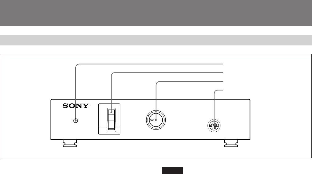
前面
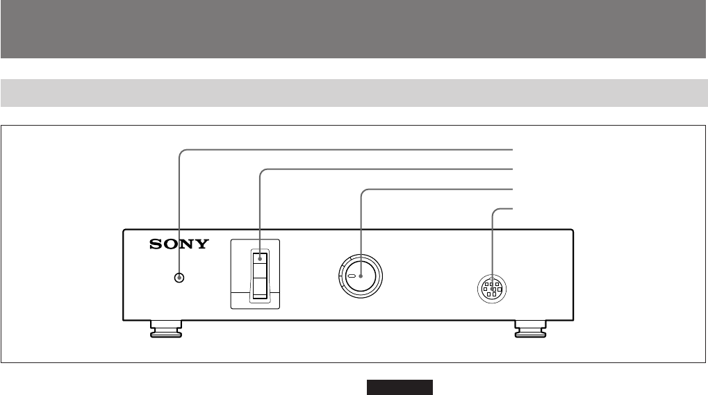
1電源インジケーター
AC電源使用時は、POWERスイッチ 2を ON にすると点灯します。
DC電源使用時は、後面のDC 15V IN端子に電源が供給されると点
灯します。
2POWER
(電源)スイッチ
AC電源使用時、本機の電源をON/OFFします。
ご注意
DC/AC SELECTスイッチが「DC」に設定してあるときは、POWERス
イッチは働きません。
3CABLE COMP
(ケーブル補償)スイッチ
接続ケーブルの長さに応じて切り換えます。
4REMOTE 端子(ミニDIN 8ピン)
リモートコントロールユニットRM-C950を接続します。
1電源インジケーター
2POWERスイッチ
3CABLE COMPスイッチ
4REMOTE端子
8
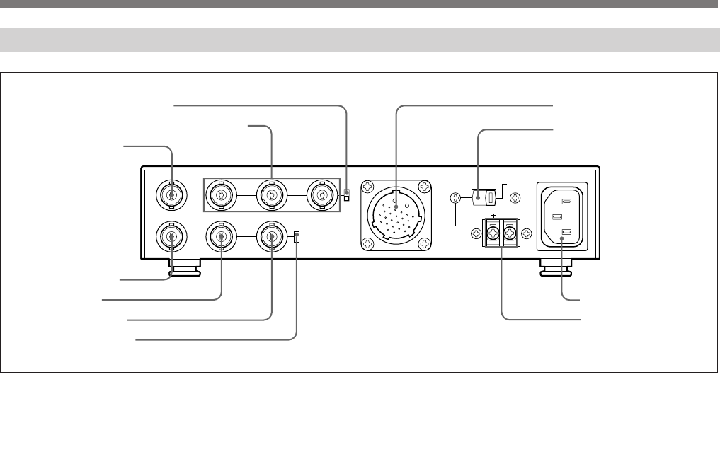
後面
WE.OUT
TRIG IN HD
G/Y OUT B/P
B
OUT R/P
R
OUT CAMERA DC/AC
SELECT
~
AC IN
DC15V
IN
VD/SYNC
IN
ON
OFF
SYNC
OUT
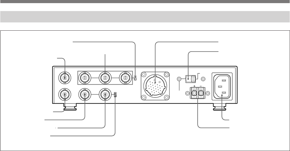
!¡DC 15V IN端子
0AC IN端子
9DC/AC SELECTスイッチ
8CAMERA端子
1SYNC ON/OFFスイッチ
2G/Y OUT, B/PB OUT, R/PR OUT端子
3WE. OUT端子
4TRIG IN端子
5HD端子
6VD/SYNC端子
7IN/OUTスイッチ
各部の名称と働き
1 SYNC ON/OFF
(同期入/切)スイッチ
G/Y OUT、B/PB OUT、R/PR OUT端子 2から同期信号を出力する
ときは「 O N 」、出 力しな いときは「 O F F 」に設定します。
2 G/Y OUT、
B/PB OUT、
R/PR OUT
(映像信号出力)端子
(BNC型)
ビデオカメラからの映像信号(GBR信号またはY/PB/PR信号)を出力
します。。映像信号の種類はビデオカメラのPAGE 3/3メニューの
「GBR/YPBPR」で設定します。
9
3 WE. OUT
(ライトイネーブルパルス出力)端子(BNC型)
外部フレームメモリーなどに画像の取り込みタイミングを知らせる、ライ
トイネーブルパルスを出力します。
◆詳しくは、DXC-H10 の取扱説明書をご覧ください。
4 TRIG IN
(トリガー入力)端子(BNC型)
トリガ ー 信 号を 入 力します 。この端子に入力されたトリガー信号により、
ビデオカメラの電子シャッタ− 機 能をコントロールすることができます。
◆詳しくは、DXC-H10 の取扱説明書をご覧ください。
5 HD
(水平同期)入出力端子(BNC型)
水平同期信号を入力または出力します。IN/OUTスイッチ 7で入力か
出 力 かを切り換えます。
6 VD/SYNC
(垂直同期/同期)入出力端子(BNC型)
垂直同期信号、または3値同期信号、2値同期信号を入力または出力
します。IN/OUTスイッチ 7で入力か出力かを切り換えます。出力す
る同期信号の種類はビデオカメラのPAGE 3/3メニューで設定します。
7 IN/OUT
(同期入力/出力)切り換えスイッチ
HD端子5とVD/SYNC端子6を入力端子として使うときは「IN」、
出力端子として使うときは「OUT」に設定します。
外部同期機能を使わないときは「OUT」に設定してください。
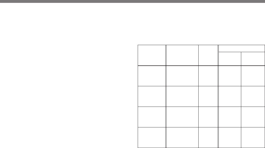
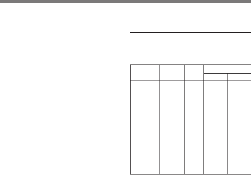
HD端子、VD/SYNC端子の使いかた
HD端子とVD/SYNC端子は、ビデオカメラのメニュー設定とIN/
OUT切り換えスイッチの組み合わせで、用途に応じて下表のようにお
使いください。
用 途
HD, VD信号
で外部同期
をかけるとき
SYNC信号
で外部同期
をかけるとき
カメラのHD,
VD出力を使
うとき
カメラの
SYNC出力を
使うとき
メニュー設定
(ビデオカメラ)
不要
不要
PAGE 3/3の
SYNC/VDを
「VD」に
PAGE 3/3の
SYNC/VDを
「SYNC」に
IN/OUT
スイッチ
の設定
IN
IN
OUT
OUT
VD/SYNC
端子
VD信号
を入力
SYNC信
号を入力
VD信号を
出力
SYNC信
号を出力
端子の入出力
HD端子
HD信号を
入力
使用しな
い
HD信号を
出力
HD信号を
出力
10
各部の名称と働き
9 DC/AC SELECT
(電源切換)スイッチ
AC IN端子に接続したAC電源で動作させるときはAC IN側(右側)、
DC 15V IN端子に接続したDC電源で動作させるときはDC 15V IN側
(左側)に切り換えます。
0 AC IN
(交流電源入力)端子
電源コード(付属)を使用して、電源コンセントへ接続します。
!¡ DC 15V IN
(直流電源入力)端子
直流電源DC 15Vへ接続します。
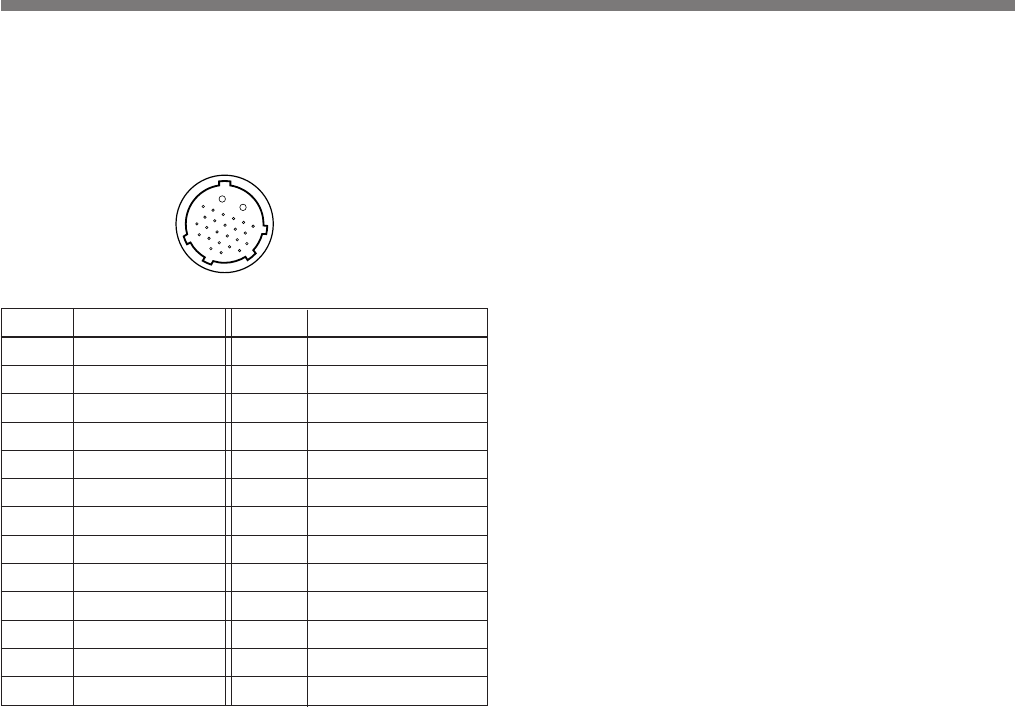
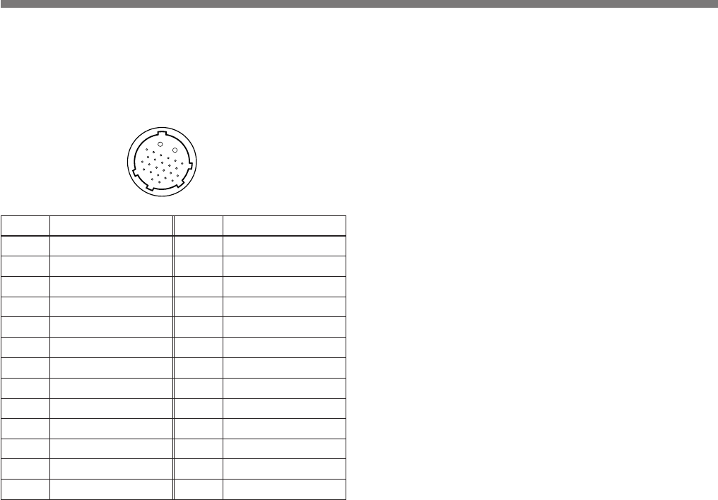
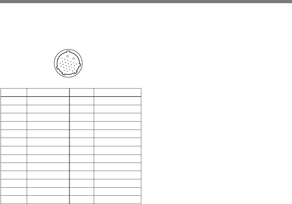
ピン番号 信号 ピン番号 信号
A 電源出力 12 WEパルス入力
Bアース(GND) 13 コントロール
1トリガー出力 14 未使用
2アース(GND) 15 未使用
3アース(GND)16アース(GND)
4 G/Y入力 17 未使用
5 R/PR入力 18 HD入出力
6アース(GND)19アース(GND)
7 B/PB入力 20 未使用
8アース(GND) 21 VD/SYNC入出力
9 未使用 22 未使用
10 未使用 23 未使用
11 未使用 24 未使用
8 CAMERA
(カメラ)端子(26ピン)
CCZ-Aカメラケーブ ルを使 用して、ビ デ オカメラ DXC-H10 の
CAMERA ADAPTOR端子と接続します。
ピン配置図
A
B
1
6
23
12
18
24
11
17
22 7
11
接続
概要
適用ビデオカメラ
本機に接続できるビデオカメラ
•HD 3CCDカラービデオカメラ DXC-H10
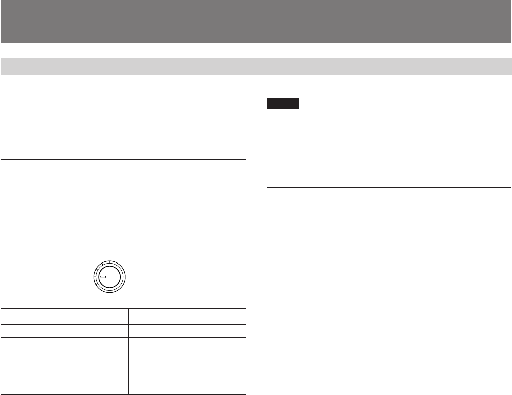
適用カメラケーブル
本機とビデオカメラを接続するカメラケーブル
•CCZ-A2/A5/A10/A25/A50/A100 (26ピンコネクター˜26ピンコネ
クター )
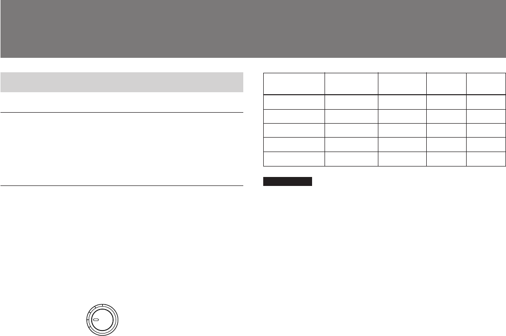
カメラケーブルの長さに応じて本機前面のCABLE COMPスイッチを
次 のように 切り換えます。
ケーブルの長さ スイッチの設定 AC電源 DC15V DC12V
10m 以下 0 ○ ○ ○
25 m 25 ○ ○ ○
50 m 50 ○ ○ ×
75 m 75 ○ ○ ×
100 m 100 ○ ○ ×
CABLE COMP
100
75
25
50
0
ご注意
•DC電源使用時は、供給電圧によって使用できるケーブルの長さが
制限されます。前記の表を参考にしてください。
•ケーブルの長さが表に該当しない場合は、スイッチを近い値に設定
してください。また、ケーブルの長さは必ず100 m以下にしてくださ
い。
電源について
本機はAC電源またはDC 15V電源で動作します。
•AC
電源
付属の電源コードを 電 源コンセントに接続し、本機後面のDC/AC
SELECTスイッチをAC IN側(右側)に設定します。
本機前面のPOWERスイッチで電源をON/OFFします。
•DC
電源
DC 15Vの外部電源をDC 15V IN端子に接続し、本機後面のDC/AC
SELECTスイッチをDC 15V IN 側(左側)に設定します。
DC 15V IN端子に電源が供給されると本機の電源が入り、電源インジ
ケーターが点灯します。(POWERスイッチは働きません。)
ラックに収納するには
別売りのラックマウントアダプターRMM-1800を使うとスタジオ用19イン
チラックにCMA-H10を4台まで収納できます。
◆詳しくは、お買い上げ店にご相談ください。
12
MENU
DATA
FLASH
CTRL IRIS
LENS
MONITOR
BARS
UP
DOWN WHITE
BLACK
60 59.94
FREQ
CAMERA ADAPTOR
FUNCTION
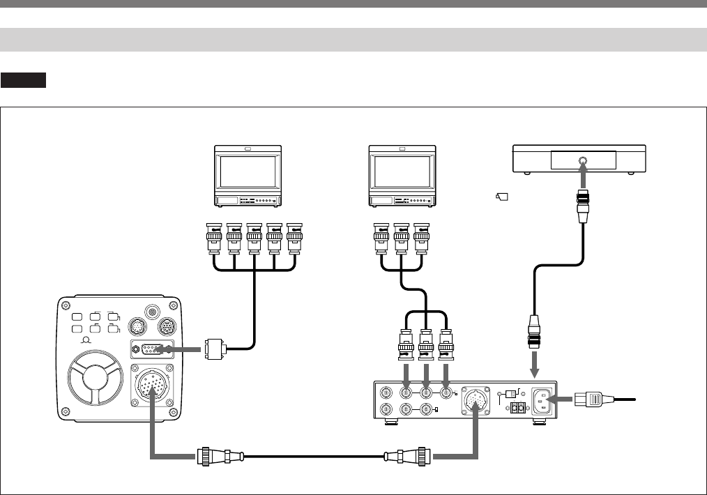
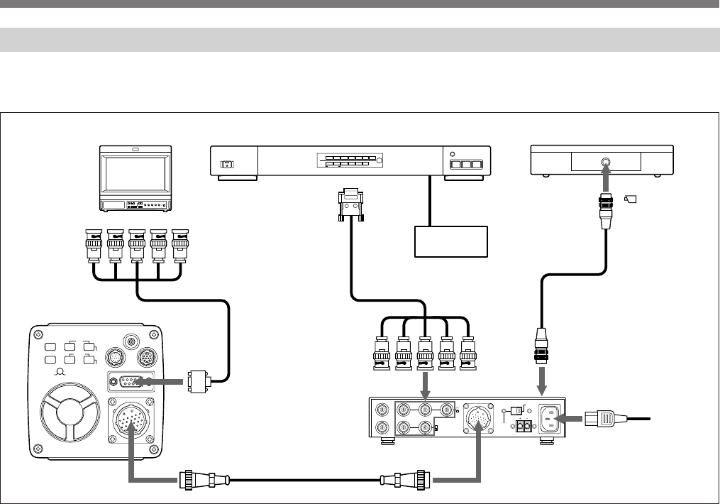
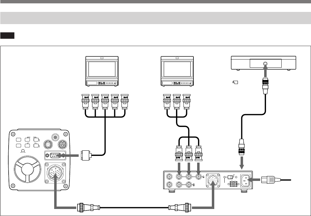
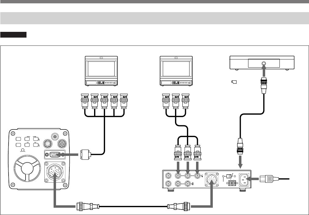
DXC-H10の基本システム接続例
ご注意 接続するすべての機器の電源を切ってください。
26ピン
カメラアダプター
CMA-H10
(本機)
G/B/RまたはY/PB/PR、
HD/VD入力へ
MONITORへ
26ピン
CCZ-Aカメラケーブル(最大100 m)
CAMERAへ
電源コード
REMOTEへ
(前面)
接続ケーブル
(RM-C950に付属)
接続ケーブル
(別売り)
G/B/Rまたは
Y/PB/PR入力へ
リモートコントロールユニット
RM-C950
HDカラービデオモニター、
プリンターなど
G/Y OUT、
B/PB OUT、
R/PR OUTへ
DXC-H10
接続
CAMERAへ
HDカラービデオモニター、
マルチスキャンモニターなど
カメラケーブル
CCXC-9DBS
(D-sub 9ピン˜ BNC x 5)
CAMERA ADAPTORへ
13
MENU
DATA
FLASH
CTRL IRIS
LENS
MONITOR
BARS
UP
DOWN WHITE
BLACK
60 59.94
FREQ
CAMERA ADAPTOR
FUNCTION
123
26ピン
26ピン
カメラアダプター
CMA-H10
(本機)
CAMERAへ
電源コード
REMOTEへ
(前面)
CCZ-Aカメラケーブル(最大100 m)
DXC-H10
カメラケーブルCCXC-9DBS
(D-sub 9ピン˜ BNC x 5)
G/B/Rまたは
Y/PB/PR、
HD/VD入力へ
接続ケーブル
(RM-C950に付属)
リモートコントロールユニット
RM-C950
G/Y OUT、
B/PB OUT、
R/PR OUT、
HD、
VD/
SYNCへ
VIDEO 3 INへVIDEO OUTへCAMERAへ
ビデオカセット
レコーダーなど
MONITORへ
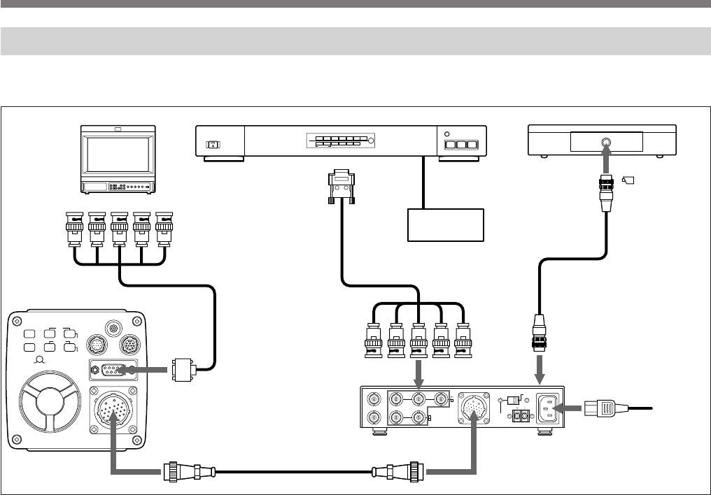
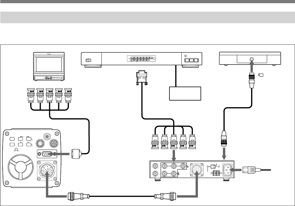
デジタルスキャンコンバーターとの接続
◆ デジタルスキャンコンバーターの操作については、デジタルスキャンコンバーターに付属の取扱説明書をご覧ください。
HDカラービデオモニター、
マルチスキャンモニターなど
接続ケーブル
(
DSC-1024G
に付属)
CAMERA ADAPTORへ
デジタルスキャンコンバーター DSC-1024G

14
主な仕様
本機の性能を保持するため
に
(使用上のご注意)
使用・保管場所
次のような場所での使用および保管は避けてください。
•極端に暑い所や寒い所(動作温度は0℃∼+40℃)
•直射日光が長時間あたる場所や暖房器具の近く
•強い磁気を発するものの近く
•強力な電波を発するテレビやラジオの送信所の近く
放熱
動作中は布などで包まないでください。内部の温度が上がり、故障や
事故の原因となります。
輸送
輸送するときは、付属のカートンとクッション、または同等品で梱包し、
強い衝撃を与えないようにしてください。
お手入れ
•外装の汚れは、乾いたやわらかい布で軽く拭き取ってください。汚れ
がひどいときは、中性洗剤溶液を少し含ませた布で汚れを拭き取っ
た後、からぶきしてください。
•アルコール、ベンジン、シンナー、殺虫剤など揮発性のものをかける
と、表面の仕上げをいためたり、表示が消えたりすることがあります。
一般
電源電圧 AC 100 V、50/60 Hz
またはDC 15 V (推奨)
出力電圧 DC 15 V、 2.2 A (AC入力時)
DC入力時はDC INの電圧に従う (CAMERA
端子より出力)
消費電力 約 40 W (AC入力時)、約 30 W (DC入力時)
ビデオカメラDXC-H10の消費電力を含む
使用温度 −5℃∼+ 45℃
保存温度 −20℃∼+ 60℃
外形寸法 210×44×210 mm(幅/高さ/ 奥行き)
突起部含まず
質量 約1.4 kg
入出力端子
CAMERA端子 26ピン丸型(メス)、バヨネットロック式
DC電源出力、GBRまたはYPBPRビデオ
入力、同期信号入力または出力、トリガ ー
出力、ライトイネーブル入力、1線式シリア
ル通信入出力

15
VD/SYNC BNC型
入力時:1 Vp-p(VD)または±0.3 V (3値
モード)または 0.3 V(2値モード)
75Ω、不平衡(終端抵抗内蔵)
出力時:1 Vp-p、75Ω、不平衡
トリガー入力端子 TRIG IN:BNC型
TTLレベル、負極性
ライトイネーブル出力端子
WE. OUT:BNC型
TTLレベル、負極性
リモート端子 REMOTE:8ピンミニ DIN型
付属品
電源コード(1)
取扱説明書(1)
保証書(1)
ソニー業務用製品ご相談窓口のご案内(1)
別売りアクセサリー
リモートコントロールユニット RM-C950
カメラケーブル CCZ-A2 (2 m) /A5 (5 m) /A10 (10 m) /A25 (25 m) /
A50 (50 m) /A100 (100 m)
本機の仕様および外観は、改良のため予告なく変更することがありま
すが、ご了承ください。
映像出力端子
G/Y OUT BNC型
映像:0.7 Vp-p
同期:±0.3 V (3値モード)または0.3 V(2値
モード)
75Ω、不平衡、SYNC ON/OFF可
B/PB OUT BNC型
映像:0.7 Vp-p(B)または±0.35 V (PB)
同期:±0.3 V (3値モード)または0.3 V(2値
モード)
75Ω、不平衡、SYNC ON/OFF可
R/PR OUT BNC型
映像:0.7 Vp-p(R)または±0.35 V (PR)
同期:±0.3 V (3値モード)または0.3 V(2値
モード)
75Ω、不平衡、SYNC ON/OFF可
同期入出力端子
HD BNC型
入力時:1 Vp-p、75Ω、不平衡(終端抵抗内
蔵)
出力時:1 Vp-p、75Ω、不平衡
VD/SYNC BNC型
入力時:1 Vp-p(VD)または±0.3 V (3値モー
ド)または0.3 V(2値モード)
75Ω、不平衡(終端抵抗内蔵)
出力時:1 Vp-p、75Ω、不平衡

16
保証書
•この製品には保証書が添付されていますので、お買い上げの際にお
受け取りください。
•所定事項の記入および記載内容をお確かめのうえ、大切に保存して
ください。
保証書とアフターサービス
アフターサービス
調子が悪いときはまずチェックを
この説明書をもう一度ご覧になってお調べください。
それでも具合の悪いときはサービスへ
お買い上げ店、または添付の「ソニー業務用製品ご相談窓口のご案
内」にあるお近くのソニーサービス窓口にご相談ください。
保証期間中の修理は
保証書の記載内容に基づいて修理させていただきます。詳しくは保証
書をご覧ください。
保証期間経過後の修理は
修理によって機能が維持できる場合は、ご要望により有料修理させて
いただきます。
保証期間中の修理など、アフターサービスについてご不明な点は、お
近くのソニーのサービス窓口にお問い合わせください。

17
18
English
Owner’s Record
The model and serial numbers are located at the bottom.
Record these numbers in the spaces provided below.
Refer to these numbers whenever you call upon your Sony
dealer regarding this product.
Model No. CMA-H10 Serial No.
For the customers in the U.S.A.
This equipment has been tested and found to comply with
the limits for a Class A digital device, pursuant to Part 15 of
the FCC Rules. These limits are designed to provide
reasonable protection against harmful interference when the
equipment is operated in a commercial environment.
This equipment generates, uses, and can radiate radio
frequency energy and, if not installed and used in
accordance with the instruction manual, may cause harmful
interference to radio communications. Operation of this
equipment in a residential area is likely to cause harmful
interference in which case the user will be required to correct
the interference at his own expense.
You are cautioned that any changes or modifications not
expressly approved in this manual could void your authority
to operate this equipment.
The shielded interface cable recommended in this manual
must be used with this equipment in order to comply with the
limits for digital device pursuant to Subpart B of Part 15 of
FCC Rules.
This symbol is intended to alert the user to the
presence of uninsulated “dangerous voltage”
within the product’s enclosure that may be of
sufficient magnitude to constitute a risk of
electric shock to persons.
This symbol is intended to alert the user to the
presence of important operating and mainte-
nance (servicing) instructions in the literature
accompanying the appliance.
WARNING
To prevent fire or shock hazard, do not
expose the unit to rain or moisture.

19
EN
Table of Contents
English
Overview
The CMA-H10 camera adaptor is designed to operate the
Sony DXC-H10 HD 3CCD color video camera on the AC or
DC power supply.
As the camera adaptor can be connected to the video camera
via a single CCZ-A series camera cable extendable up to
100 m, the video camera can be installed far from a control
room.
Precautions ........................................................................20
Safety Precautions .......................................................20
Handling Precautions ...................................................20
Location and Functions of Parts .....................................22
Front Panel ...................................................................22
Rear Panel ....................................................................23
Connections .......................................................................26
Outline .........................................................................26
Basic System Configuration for the DXC-H10 ...........28
Connecting to a Digital Scan Converter ......................29
Specifications...............................................................30

20
Precautions
Safety Precautions
Power supply
• The unit is designed for operation on a power supply
meeting the requirements indicated in the “Specifications”
on page 30.
• Do not drop or place heavy objects on the power cord. If
the power cord is damaged, turn off the power
immediately. It is dangerous to use the unit with a
damaged power cord.
• Disconnect the power cord from the AC outlet by grasping
the plug, not by pulling the cord.
• Do not touch the AC power plug with wet hand.
Keep foreign objects out of the cabinet
Dropping frammable or metal objects into the cabinet, or
spilling liquids nearly can lead to accidents.
In case of malfunctions
If you notice any unusual sound, smell, or smoke, turn off
the power immediately, disconnect the power supply and
contact your Sony dealer.
Handling Precautions
Location
Do not store or use the unit under any of the following
conditions.
• In excessive heat or cold
• In direct sunlight or near heater
• In damp or dusty locations
• In locations subject to vibrations
• Near strong magnetic fields
• Near television or radio station generating strong radio
frequency energy
Protect from impact
Do not drop the unit or subject it to severe shocks.
Do not place the unit on an unstable base.
Use on the DC power supply
• Use a DC power supply capable of supplying constant
voltage of 33 W or more.
• As the power switch of this unit does not operate on DC,
provide the power switch and fuse on the DC power source
for safety.

21
• When connecting the DC power cable to the DC 15 V IN
connector, take special care with the following:
– use a DC power cable of a sufficient current capacity.
– align the polarities correctly.
– make sure that there is no loose connection or short-
circuit on the conductors.
Ventilation
To prevent internal heat buildup, do not block air circulation
around the unit.
Transportation
When transporting the unit, repack it as originally packed at
the factory or in materials equal in quality.
Cleaning
Clean the cabinet and panels by wiping with a soft, dry
cloth. For severe stains, moisten the cloth with a small
amount of neutral solvent, and finish by wiping with a dry
cloth. Do not use alcohol, benzine, thinner or volatile
liquids, as these may discolor or damage the cabinet surface.
22
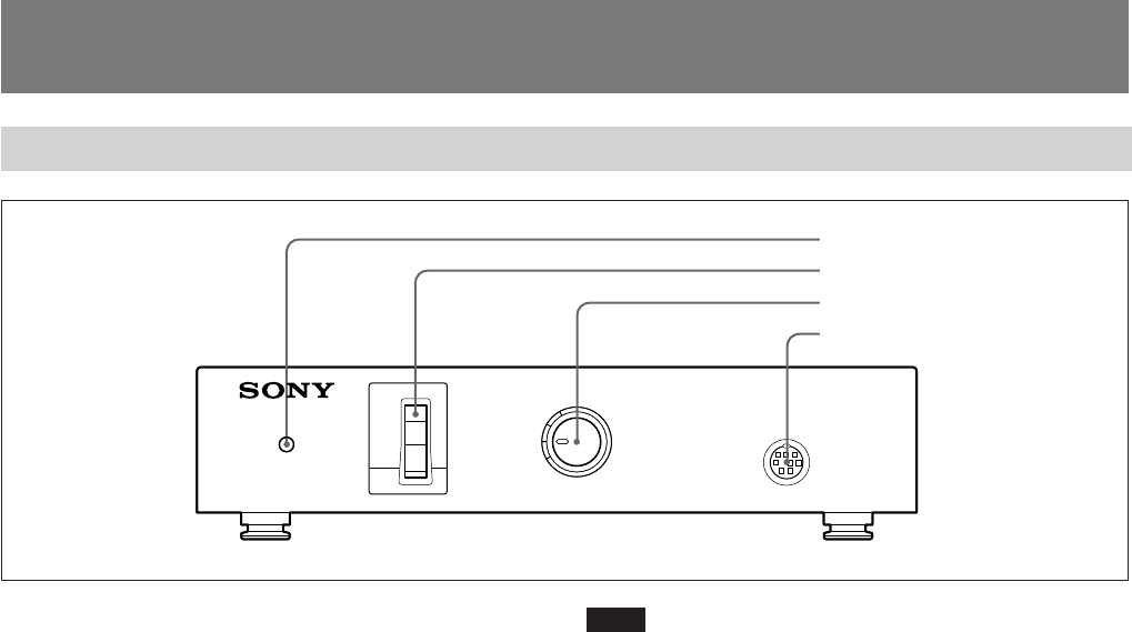
Note
The POWER switch does not operate when the DC/AC
SELECT switch is set to DC.
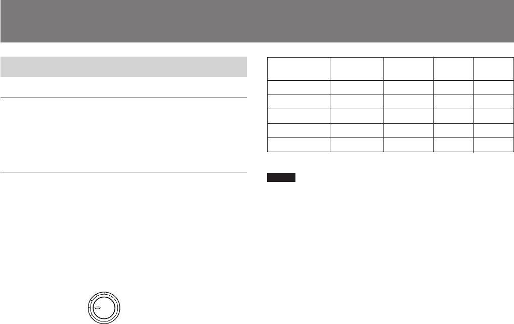
3CABLE COMP (cable compensation) selector
Set the selector to the appropriate position according to the
connected cable length.
4REMOTE (remote control) connector (mini DIN, 8-
pin)
Connect to the RM-C950 remote control unit.
POWER
ON
OFF
CABLE COMP REMOTE
100
75
25
50
0
CAMERA ADAPTOR CMA-H10
4 REMOTE connector
Location and Functions of Parts
3 CABLE COMP selector
1 Power indicator
2 POWER switch
1Power indicator
For AC operation, the indicator lights when you set the
POWER switch 2 to ON.
For DC operation, it lights when you supply power to the
DC 15V IN connector on the rear panel.
2POWER switch
For AC operation, set the switch to ON to turn on the power
of the unit.
Front Panel

23
WE.OUT
TRIG IN HD
G/Y OUT B/P
B
OUT R/P
R
OUT CAMERA DC/AC
SELECT
~
AC IN
DC15V
IN
VD/SYNC
IN
ON
OFF
SYNC
OUT
1 SYNC ON/OFF switch 8CAMERA connector
9 DC/AC SELECT switch
!º AC IN connector
!¡ DC 15 V IN connector
1SYNC ON/OFF switch
Set the switch to ON to output the sync signal from the G/Y
OUT, B/PB OUT and R/PR OUT connectors 2.
Set the switch to OFF so that the sync signal is not output.
2G/Y OUT, B/PB OUT and R/PR OUT (video signal
output) connectors (BNC type)
Outputs the video signal (GBR or Y/PB/PR) supplied from
the video camera.
The type of the video signal is set by the GBR/YPBPR item
in the PAGE 3/3 menu of the video camera.
Rear Panel
2 G/Y OUT, B/PB OUT and R/PR OUT connectors
3 WE. OUT connector
7 IN/OUT selector
5 HD connector
4 TRIG IN connector
6 VD/SYNC connector
24
Location and Functions of Parts
3WE. OUT (Write Enable pulse output) connector
(BNC type)
Outputs the WE pulse to communicate the timing to store
the image on an external frame memory, etc.
For detailed information, read the instruction manual of the
DXC-H10.
4TRIG IN (trigger input) connector (BNC type)
Inputs the trigger pulse. You can control the electronic
shutter by using the trigger pulse input to this connector.
For detailed information, read the instruction manual of the
DXC-H10.
5HD (horizontal deflection) input/output connector
(BNC type)
Inputs or outputs the HD signal. Input or output can be
selected by setting the IN/OUT selector 7.
6VD/SYNC (vertical deflection/sync) input/output
connector (BNC type)
Inputs or outputs the vertical deflection signal, tri-level sync
signal or bi-level sync signal. Input or output can be selected
by setting the IN/OUT selector 7.
The type of sync signal is set on the PAGE 3/3 menu of the
video camera.
Using the HD and VD/SYNC connectors
The following table shows how to use the HD and VD/
SYNC connectors combined with the menu setting on the
video camera and the IN/OUT selector on this unit.
7IN/OUT (sync input/output) selector
Set to IN to use the HD connector 5 and VD/SYNC
connector 6 as inputs, and to OUT to use them as outputs.
It should be set to OUT when external sync is not used.
Purpose
To use HD and
VD signals for
external sync
To use SYNC
signal for
external sync
To use HD and
VD signals
output from the
camera
To use SYNC
signal output
from the
camera
Function of connector
HD
HD signal
input
Not used
HD signal
output
HD signal
output
VD/SYNC
VD signal
input
SYNC
signal input
VD signal
output
SYNC
signal
output
Menu
setting on
camera
Any
Any
Set SYNC/
VD to VD on
PAGE 3/3
menu
Set SYNC/
VD to SYNC
on PAGE 3/
3 menu
IN/OUT
selector
setting
IN
IN
OUT
OUT
25
Pin No. Signal
A Power output
B GND
1 Trigger output
2 GND
3 GND
4 G/Y input
5 R/PR input
6 GND
7 B/PB input
8 GND
9—
10 —
11 —
Pin No. Signal
12 WE pulse input
13 Control
14 —
15 —
16 GND
17 —
18 HD input/output
19 GND
20 —
21 VD/SYNC input/output
22 —
23 —
24 —
9DC/AC SELECT switch
Set to the right position (AC IN) to operate the video camera
on the AC power supply connected to the AC IN connector.
Set to the left position (DC 15V IN) to operate the video
camera on the DC power supply connected to the DC 15V
IN connector.
0AC IN connector
Connect to an AC outlet using the AC power cord
(supplied).
!¡ DC 15V IN connector
Connect to the 15V DC power supply.
9CAMERA connector (26-pin)
Connect to the CAMERA ADAPTOR connector on the
DXC-H10 video camera using the CCZ-A series camera
cable.
Pin assignment
A
B
1
6
23
12
18
24
11
17
22 7
26
Cable length
10 m or less
Approx. 25 m
Approx. 50 m
Approx. 75 m
Approx. 100 m
Connections
Outline
Applicable cameras
You can connect the following Sony video camera to the
unit.
• HD 3CCD color video camera DXC-H10
Usable camera cable
The following camera cables can be used to connect the unit
to a video camera.
• CCZ-A2/A5/A10/A25/A50/A100 (26-pin to 26-pin
connectors)
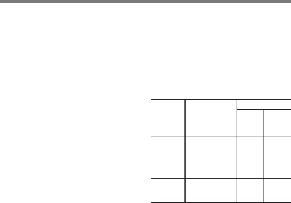
Set the CABLE COMP selector on the front panel to the
appropriate position according to the camera cable length.
Notes
• For DC operation, the usable cable length is limited by the
supply voltage. Refer to the table above.
• If your cable length is not indicated in the table, set the
selector to a position for a closer length. Do not use a
cable of more than 100 m.
CABLE COMP
100
75
25
50
0
AC power 15 V DC 12 V DC
OKOKOK
OKOKOK
OKOKNG
OKOKNG
OKOKNG
Selector
setting
0
25
50
75
100

27
Power supply
The unit operates on either AC or 15V DC power supply.
AC power
Connect the AC power cord (supplied) to an AC outlet and
set the DC/AC SELECT switch on the rear panel to AC IN
(right). You can turn on and off the unit with the POWER
switch on the front panel.
DC power
Connect a 15V DC external power source to the DC 15V IN
connector and set the DC/AC SELECT switch on the rear
panel to DC 15V IN (left).
The power indicator lights when power is supplied to the
DC 15V IN connector. (The POWER switch on this unit
does not operate when using DC power.)
Mounting the unit in a rack
You can mount up to four CMA-H10 camera adaptors in a
19-inch rack using the RMM-1800 rack mount adaptor.
For more information on the RMM-1800, contact your Sony
dealer.
28
MENU
DATA
FLASH
CTRL IRIS
LENS
MONITOR
BARS
UP
DOWN WHITE
BLACK
60 59.94
FREQ
CAMERA ADAPTOR
FUNCTION
HD color video monitor, printer, etc.
HD color video monitor, multi-scan monitor, etc.
RM-C950 remote control unit
CAMERA
G/B/R or Y/P B/P R
inputs, and HD/VD inputs
G/B/R or Y/P B/P R
inputs
DXC-H10 CCXC-9DBS camera cable
(D-sub 9-pin ˜ 5BNC)
Connecting cable (not supplied) Connecting cable (supplied with the RM-C950)
REMOTE (front)
CMA-H10
camera adaptor
26-pin 26-pin
Power cord
CCZ-A camera cable (100 m max.)
CAMERA ADAPTOR CAMERA
MONITOR
Connections
Basic System Configuration for the DXC-H10
Note Turn off the power to all the units before making any connections.
G/Y OUT, B/P B OUT
and R/P R OUT
29
MENU
DATA
FLASH
CTRL IRIS
LENS
MONITOR
BARS
UP
DOWN WHITE
BLACK
60 59.94
FREQ
CAMERA ADAPTOR
FUNCTION
123
VCR, etc.
HD color video monitor or multi-scan monitor
Digital scan converter DSC-1024G RM-C950 remote control unit
VIDEO 3 IN VIDEO OUT CAMERA
G/B/R or
Y/P B/P R
inputs, and HD/VD
inputs CCXC-9DBS camera cable
(D-sub 9-pin ˜ 5BNC) Connecting cable (supplied with the DSC-1024G) Connecting cable (supplied with the RM-C950)
REMOTE (front)
CMA-H10
camera adaptor
26-pin 26-pin
Power cord
CCZ-A camera cable (100 m max.)
G/Y OUT, B/P B OUT,
R/P R OUT, HD,
VD/SYNC
MONITOR
CAMERA
ADAPTOR
DXC-H10
CAMERA
Connecting to a Digital Scan Converter
For details on the digital scan converter, refer to the Operating Instructions supplied with the converter.

30
Specifications
General
Power requirements
120 V AC, 50/60 Hz
15 V DC (recommended)
DC output 15 V DC, 2.2 A (on AC operation)
DC voltage specified by the DC power supply
(output from the CAMERA connector)
Power consumption
Approx. 40 W (on AC operation)
Approx. 30 W (on DC operation)
including the power consumption of the DXC-
H10 video camera
Operating temperature
-5 °C to +45 °C (23 °F to 113 °F)
Storage temperature
-20 °C to +60 °C (-4 °F to 140 °F)
Dimensions 210 × 44 × 210 mm (8 3/8 × 1 3/4 × 8 3/8
inches) (w/h/d), not including the projecting
parts
Mass Approx. 1.4 kg (3 lb 1 oz)
Inputs/Outputs
CAMERA connector
26-pin female, bayonet-lock type
DC power output, GBR/YPBPR video input,
sync input/output, trigger output, WE pulse
input, single-line serial communication
input/output
Video output connectors
G/Y OUT: BNC type
video: 0.7 Vp-p
sync: ±0.3V (tri-level) or 0.3 V (bi-level)
75 ohms, unbalanced, SYNC ON/OFF
switchable
B/PB OUT: BNC type
video: 0.7 Vp-p (B) or ±0.35V (PB)
sync: ±0.3V (tri-level) or 0.3 V (bi-level)
75 ohms, unbalanced, SYNC ON/OFF
switchable
R/PR OUT: BNC type
video: 0.7 Vp-p (R) or ±0.35V (PR)
sync: ±0.3 V (tri-level) or 0.3 V (bi-level)
75 ohms, unbalanced, SYNC ON/OFF
switchable

31
Sync input/output connectors
HD: BNC type
Input: 1Vp-p, 75 ohms, unbalanced (with
built-in terminator)
Output: 1 Vp-p, 75 ohms, unbalanced
VD/SYNC: BNC type
Input: 1 Vp-p (VD), ±0.3 V (tri-level) or
0.3 V (bi-level)
75 ohms, unbalanced (with built-in
terminator)
Output: 1 Vp-p, 75 ohms, unbalanced
Trigger input connector
TRIG IN: BNC type
TTL level, negative
WE pulse output connector
WE. OUT: BNC type
TTL level, negative
Remote control connector
REMOTE: mini DIN 8-pin
Supplied accessories
AC power cord (1)
Operating Instructions (1)
Optional accessories
Remote control unit RM-C950
Camera cables CCZ-A2 (2 m, 6.5 ft)
CCZ-A5 (5 m, 16.5 ft)
CCZ-A10 (10 m, 33 ft)
CCZ-A25 (25 m, 82 ft)
CCZ-A50 (50 m, 164 ft)
CCZ-A100 (100 m, 330 ft)
Design and specifications are subject to change without
notice.

32
Français
AVERTISSEMENT
Afin d’éviter tout risque d’incendie et
d’électrocution, ne pas exposer l’appareil
à la pluie ou à l’humidité.
Pour éviter tout risque de décharge
électrique, ne pas ouvrir le boîtier. Confiez
l’entretien uniquement à un personnel
qualifié.

33
F
Table des matières
Français
Présentation
L’adaptateur de caméra CMA-H10 est conçu pour fournir
une alimentation CA ou CC à une caméra vidéo couleur HD
3CCD Sony DXC-H10.
Comme l’adaptateur de caméra peut être raccordé à une
caméra vidéo via un simple câble de caméra CCZ-A
extensible jusqu’à 100 m, la caméra vidéo peut être installée
loin du poste de contrôle.
Précautions ........................................................................34
Précautions de sécurité ................................................ 34
Précautions de manipulation ........................................34
Localisation et fonctions des composants .......................36
Panneau frontal ............................................................36
Panneau arrière ............................................................37
Raccordement ...................................................................40
Description...................................................................40
Configuration système de base pour la DXC-H10 ......42
Raccordement à un convertisseur de balayage
numérique .........................................................43
Spécifications...............................................................44

34
Précautions
Précautions de sécurité
Alimentation
• Cet appareil est conçu pour fonctionner sur une
alimentation compatible avec les indications précisées dans
les “Spécifications” à la page 44.
• Ne laissez pas tomber le cordon d’alimentation et ne posez
pas d’objets lourds dessus. Si le cordon d’alimentation est
endommagé, mettez immédiatement l’appareil hors
tension. Il est dangereux de faire fonctionner l’appareil
avec un cordon d’alimentation endommagé.
• Déconnectez le cordon d’alimentation de la prise murale en
le saisissant par la fiche. Ne tirez jamais sur le cordon
proprement dit.
• Ne touchez pas la fiche d’alimentation secteur lorsque vous
avez les mains mouillées.
Ne laissez pas pénétrer d’objets dans le boîtier
La pénétration d’objets inflammables ou métalliques à
l’intérieur du boîtier ou l’écoulement de liquides à proximité
peut constituer une source d’accidents.
En cas de dysfonctionnement
Si vous constatez des bruits, des odeurs inhabituels ou de la
fumée, mettez immédiatement l’appareil hors tension et
déconnectez le cordon d’alimentation. Consultez sans tarder
votre revendeur Sony.
Précautions de manipulation
Installation
Evitez de stocker et d’utiliser l’appareil dans les conditions
suivantes.
• Sous une chaleur ou un froid excessif
• Sous le rayonnement direct du soleil ou à proximité d’un
chauffage
• Dans un endroit humide ou poussiéreux
• Dans un endroit soumis à des vibrations
• A proximité de puissants champs magnétiques
• A proximité d’un poste de radio ou de télévision générant
de puissantes radiofréquences
Protection contre les impacts
Ne laissez pas tomber l’appareil et ne le soumettez pas à des
chocs violents.
Ne placez pas l’appareil sur un support instable.
Utilisation sur une alimentation continue
• Utilisez une alimentation CC capable d’assurer une tension
constante de 33 W ou plus.
• Comme l’interrupteur d’alimentation de cet appareil ne
fonctionne pas sur courant continu, installez un
interrupteur d’alimentation et un fusible sur le bloc
d’alimentation CC pour plus de sécurité.

35
• Lorsque vous branchez un câble d’alimentation CC sur le
connecteur DC 15 V IN, veillez plus particulièrement aux
précautions suivantes:
– utilisez un câble d’alimentation CC d’une capacité de
courant suffisante.
– alignez correctement les polarités.
– assurez-vous que les conducteurs ne comportent pas de
connexions lâches ni de court-circuits.
Ventilation
Pour éviter toute surchauffe interne, n’entravez pas la
circulation de l’air autour de l’appareil.
Transport
Pour transporter l’appareil, remballez-le comme à l’origine
ou dans des matériaux de conditionnement de qualité
équivalente.
Entretien
Nettoyez le boîtier et les panneaux avec un chiffon doux et
sec. En cas de souillures tenaces, utilisez un chiffon
légèrement imprégné d’une solution détergente neutre et
essuyez ensuite avec un chiffon sec. N’utilisez en aucun cas
des solvants puissants tels que du diluant ou de la benzine ni
de liquides volatiles, qui risqueraient de décolorer ou
d’altérer le fini du châssis.
36
Remarque
L’interrupteur POWER ne fonctionne pas lorsque le
sélecteur DC/AC SELECT est réglé sur DC.
3Sélecteur CABLE COMP (compensation de câble)
Réglez le sélecteur sur la position appropriée en fonction de
la longueur du câble à raccorder.
4Connecteur REMOTE (télécommande)
(miniconnecteur DIN, 8 broches)
Raccordez-le à l’unité de télécommande RM-C950.
POWER
ON
OFF
CABLE COMP REMOTE
100
75
25
50
0
CAMERA ADAPTOR CMA-H10
4 Connecteur REMOTE
Localisation et fonction des composants
3 Sélecteur CABLE COMP
1 Indicateur d’alimentation
2 Interrupteur POWER
1Indicateur d’alimentation
En mode de fonctionnement CA, cet indicateur s’allume
lorsque vous réglez l’interrupteur POWER 2 sur ON.
En mode de fonctionnement CC, il s’allume lorsque vous
assurez l’alimentation via le connecteur DC 15V IN du
panneau arrière.
2Interrupteur POWER
En mode de fonctionnement CA, réglez l’interrupteur sur
ON pour mettre l’appareil sous tension.
Panneau frontal
37
WE.OUT
TRIG IN HD
G/Y OUT B/P
B
OUT R/P
R
OUT CAMERA DC/AC
SELECT
~
AC IN
DC15V
IN
VD/SYNC
IN
ON
OFF
SYNC
OUT
1 Commutateur SYNC ON/OFF 8Connecteur CAMERA
9 Sélecteur DC/AC SELECT
!º Connecteur AC IN
!¡ Connecteur DC 15 V IN
1Commutateur SYNC ON/OFF
Réglez ce commutateur sur ON pour sortir le signal de
synchronisation via les connecteurs G/Y OUT, B/PB OUT et
R/PR OUT 2.
Réglez le commutateur sur OFF de façon à empêcher la
transmission du signal de synchronisation.
Panneau arrière
2 Connecteurs G/Y OUT, B/PB OUT et R/PR OUT
3 Connecteur WE. OUT
7 Sélecteur IN/OUT
5 Connecteur HD
4 Connecteur TRIG IN
6 Connecteur VD/SYNC
2Connecteurs G/Y OUT, B/PB OUT et R/PR OUT
(sortie du signal vidéo) (type BNC)
Sortie du signal vidéo (GBR ou Y/PB/PR) transmis par la
caméra vidéo.
Le type de signal vidéo est défini par le paramètre GBR/
YPBPR dans le menu PAGE 3/3 de la caméra vidéo.
38
Localisation et fonction des composants
3Connecteur WE. OUT (sortie d’impulsion
inscriptible) (type BNC)
Sortie de l’impulsion WE pour communiquer la
temporisation d’enregistrement de l’image dans une
mémoire d’image externe, etc.
Pour des informations plus détaillées, reportez-vous au
mode d’emploi du DXC-H10.
4Connecteur TRIG IN (entrée de déclenchement)
(type BNC)
Entrée de l’impulsion de déclenchement. Vous pouvez
commander l’obturateur électronique à l’aide de l’impulsion
de déclenchement entrée via ce connecteur.
Pour des informations plus détaillées, reportez-vous au
mode d’emploi du DXC-H10.
5Connecteur d’entrée/sortie HD (déflexion
horizontale) (type BNC)
Entrée ou sortie du signal HD. L’entrée ou la sortie peut être
sélectionnée au moyen du sélecteur IN/OUT 7.
6Connecteur d’entrée/sortie VD/SYNC (déflexion
verticale/synchronisation) (type BNC)
Entrée ou sortie du signal de déflexion verticale, du signal
de synchronisation à trois niveaux ou du signal de
synchronisation à deux niveaux. L’entrée ou la sortie peut
être sélectionnée au moyen du sélecteur IN/OUT 7.
Le type de signal de synchronisation est défini dans le menu
PAGE 3/3 de la caméra vidéo.
7Sélecteur IN/OUT (entrée/sortie de synchronisation)
Réglez-le sur IN pour utiliser le connecteur HD 5 et le
connecteur VD/SYNC 6 comme entrées, et sur OUT pour
Utilisation des connecteurs HD et VD/SYNC
Le tableau ci-dessous vous indique comment utiliser les
connecteurs HD et VD/SYNC en combinaison avec le
réglage du menu de la caméra vidéo et le sélecteur IN/OUT
de cet appareil.
Objet
Utilisation des
signaux HD et
VD comme
synchronisation
externe
Utilisation du
signal SYNC
comme
synchronisation
externe
Transmission
des signaux HD
et VD depuis la
caméra vidéo
Transmission du
signal SYNC
depuis la
caméra vidéo
Fonction du connecteur
HD
Entrée
signal HD
Inutilisé
Sortie
signal HD
Sortie
signal HD
VD/SYNC
Entrée
signal VD
Entrée
signal
SYNC
Sortie
signal VD
Sortie
signal
SYNC
Réglage
menu sur la
caméra
Sans
importance
Sans
importance
Réglez SYNC/
VD sur VD
dans le menu
PAGE 3/3
Réglez SYNC/
VD sur SYNC
dans le menu
PAGE 3/3
Réglage
sélecteur
IN/OUT
IN
IN
OUT
OUT
les utiliser comme sorties.
Il doit être réglé sur OUT si vous n’utilisez pas de signal de
synchronisation externe.
39
9Sélecteur DC/AC SELECT
Réglez-le sur la position de droite (AC IN) pour faire
fonctionner la caméra vidéo sur l’alimentation CA transmise
par la source d’alimentation CA raccordé au connecteur AC
IN.
Réglez-le sur la position de gauche (DC 15V IN) pour faire
fonctionner la caméra vidéo sur l’alimentation CC transmise
par la source d’alimentation CC raccordé au connecteur DC
15V IN.
0Connecteur AC IN
Raccordez-le à une prise murale (secteur) à l’aide du cordon
d’alimentation (fourni).
!¡ Connecteur DC 15V IN
Raccordez-le à la source d’alimentation 15 V CC.
9Connecteur CAMERA (26 broches)
Raccordez-le au connecteur CAMERA ADAPTOR de la
caméra vidéo DXC-H10 à l’aide du câble de caméra CCZ-A.
Assignation des broches
A
B
1
6
23
12
18
24
11
17
22 7
Broches No.
Signal
A Sortie alimentation
B GND
1
Sortie déclenchement
2 GND
3 GND
4 Entrée G/Y
5 Entrée R/PR
6 GND
7 Entrée B/PB
8 GND
9—
10 —
11 —
Broche No.
Signal
12
Entrée impulsion WE
13 Commande
14 —
15 —
16 GND
17 —
18 Entrée/sortie HD
19 GND
20 —
21
Entrée/sortie VD/SYNC
22 —
23 —
24 —
40
CMA-H10.3-862-186-01 (1) J/E/F
Raccordement
Description
Caméras compatibles
Vous pouvez raccorder la caméra vidéo Sony suivante à
l’appareil.
• Caméra vidéo couleur HD 3CCD DXC-H10
Câble de caméra utilisable
Les câbles de caméra suivants peuvent être utilisés pour
raccorder l’appareil à une caméra vidéo.
• CCZ-A2/A5/A10/A25/A50/A100 (connecteurs 26 broches
à 26 broches)
Réglez le sélecteur CABLE COMP du panneau frontal sur la
position appropriée en fonction de la longueur du câble de
caméra.
Remarques
• En mode de fonctionnement CC, la longueur de câble
utilisable est limitée par la tension d’alimentation.
Reportez-vous au tableau ci-dessus.
• Si la longueur de votre câble n’est pas indiquée dans le
tableau, réglez le sélecteur sur la position correspondant à
une longueur voisine de celle de votre câble. N’utilisez pas
de câble de plus de 100 m.
CABLE COMP
100
75
25
50
0
Longueur de
câble
10 m ou moins
Approx. 25 m
Approx. 50 m
Approx. 75 m
Approx. 100 m
Secteur (CA)
15 V CC 12 V CC
OK OK OK
OK OK OK
OK OK NG
OK OK NG
OK OK NG
Réglage du
sélecteur
0
25
50
75
100

41
CMA-H10.3-862-186-01 (1) J/E/F
Alimentation
L’appareil fonctionne sur une alimentation CA ou de 15 V
CC.
Alimentation CA
Branchez le cordon d’alimentation CA (fourni) sur une prise
murale (secteur) et réglez le sélecteur DC/AC SELECT du
panneau arrière sur AC IN (droite). Vous pouvez mettre
l’appareil sous et hors tension avec l’interrupteur POWER
du panneau frontal.
Alimentation CC
Branchez une source d’alimentation 15 V CC externe sur le
connecteur DC 15V IN et réglez le sélecteur DC/AC
SELECT du panneau arrière sur DC 15V IN (gauche).
L’indicateur d’alimentation s’allume lorsque l’alimentation
est transmise via le connecteur DC 15V IN. (L’interrupteur
POWER de cet appareil est inopérant en mode de
fonctionnement CC.)
Installation de l’appareil dans une étagère
Vous pouvez monter jusqu’à quatre adaptateurs de caméra
CMA-H10 dans une étagère de 19 pouces en utilisant un
adaptateur de montage pour étagère RMM-1800.
Pour plus d’informations sur l’adaptateur RMM-1800,
consultez votre revendeur Sony.
42
CMA-H10.3-862-186-01 (1) J/E/F
MENU
DATA
FLASH
CTRL IRIS
LENS
MONITOR
BARS
UP
DOWN WHITE
BLACK
60 59.94
FREQ
CAMERA ADAPTOR
FUNCTION
Moniteur vidéo
couleur HD,
imprimante,
etc.
Moniteur vidéo
couleur HD,
moniteur multi-
scan, etc.
Unité de télécommande RM-C950
CAMERA
Entrées G/B/R ou
Y/PB/PR et entrées
HD/VD
Entrées G/B/R
ou Y/PB/PR
DXC-H10 Câble de caméra
CCXC-9DBS
(D-sub 9 broches ˜ 5BNC)
Câble de connexion
(non fourni) Câble de connexion (fourni
avec la RM-C950)
REMOTE (avant)
Adaptateur de
caméra CMA-H10
26 broches 26 broches
Cordon d’alimentation
Câble de caméra CCZ-A
(100 m max.)
CAMERA ADAPTOR CAMERA
MONITOR
Raccordement
Configuration système de base pour la DXC-H10
G/Y OUT, B/PB OUT et
R/PR OUT
Remarque Mettez tous les appareils hors tension avant de procéder à quelque connexion que ce soit.
43
CMA-H10.3-862-186-01 (1) J/E/F
MENU
DATA
FLASH
CTRL IRIS
LENS
MONITOR
BARS
UP
DOWN WHITE
BLACK
60 59.94
FREQ
CAMERA ADAPTOR
FUNCTION
123
Magnétoscope,
etc.
Moniteur
vidéo couleur
HD ou
moniteur
multi-scan
Convertisseur de balayage numérique DSC-1024G Unité de télécommande RM-C950
VIDEO 3 IN VIDEO OUT CAMERA
Entrées
G/B/R ou
Y/PB/PR et
entrées
HD/VD
Câble de caméra CCXC-9DBS
(D-sub 9 broches ˜ 5 BNC) Câble de connexion
(fourni avec le DSC-1024G) Câble de connexion (fourni
avec la RM-C950)
REMOTE (avant)
Adaptateur de
caméra CMA-H10
26 broches
Cordon d’alimentation
Câble de caméra CCZ-A
(100 m max.)
G/Y OUT, B/PB OUT,
R/PR OUT, HD,
VD/SYNC
MONITOR
CAMERA
ADAPTOR
DXC-H10
CAMERA
Raccordement à un convertisseur de balayage numérique
Pour plus de détails sur le convertisseur de balayage numérique, reportez-vous au mode d’emploi fourni avec le
convertisseur.
26 broches

44
CMA-H10.3-862-186-01 (1) J/E/F
Spécifications
Caractéristiques générales
Puissance de raccordement
120 V CA, 50/60 Hz
15 V CC (conseillée)
Tension de sortie CC
15 V CC, 2,2 A (fonctionnement CA)
Tension CC spécifiée par l’alimentation CC
(sortie via le connecteur CAMERA)
Consommation électrique
Approx. 40 W (fonctionnement CA)
Approx. 30 W (fonctionnement CC)
y compris la consommation électrique de la
caméra vidéo DXC-H10
Température d’utilisation
-5 °C à +45 °C (23 °F à 113 °F)
Température de stockage
-20 °C à +60 °C (-4 °F à 140 °F)
Dimensions 210 × 44 × 210 mm (8 3/8 × 1 3/4 × 8 3/8 po)
(l/h/p), parties saillantes non comprises
Masse Approx. 1,4 kg (3 lb 1 oz)
Entrées/sorties
Connecteur CAMERA
Connecteur femelle à 26 broches, type à
baïonnette
Sortie d’alimentation CC, entrée vidéo
GBR/YPBPR, entrée/sortie de
synchronisation, sortie de déclenchement,
entrée d’impulsion WE, entrée/sortie de
communication sérielle monoligne
Connecteurs de sortie vidéo
G/Y OUT: type BNC
vidéo: 0,7 Vcc
synchronisation: ±0,3 V (trois niveaux) ou
0,3 V (deux niveaux)
75 ohms, asynchrone, commutable SYNC
ON/OFF
B/PB OUT: type BNC
vidéo: 0,7 Vcc (B) ou ±0,35 V (PB)
synchronisation: ±0,3 V (trois niveaux) ou
0,3 V (deux niveaux)
75 ohms, asynchrone, commutable SYNC
ON/OFF
R/PR OUT: type BNC
vidéo: 0,7 Vcc (R) ou ±0,35 V (PR)
synchronisation: ±0,3 V (trois niveaux) ou
0,3 V (deux niveaux)
75 ohms, asynchrone, commutable SYNC
ON/OFF

45
CMA-H10.3-862-186-01 (1) J/E/F
Connecteurs d’entrée/sortie de synchronisation
HD: type BNC
Entrée: 1 Vcc, 75 ohms, asynchrone
(terminaison intégrée)
Sortie: 1 Vcc, 75 ohms, asynchrone
VD/SYNC: type BNC
Entrée: 1 Vcc (VD), ±0,3 V (trois niveaux)
ou 0,3 V (deux niveaux)
75 ohms, asynchrone (terminaison intégrée)
Sortie: 1 Vcc, 75 ohms, asynchrone
Connecteur d’entrée de déclenchement
TRIG IN: type BNC
Niveau TTL, négatif
Connecteur de sortie d’impulsion WE
WE. OUT: type BNC
Niveau TTL, négatif
Connecteur de télécommande
REMOTE: miniconnecteur DIN à 8 broches
Accessoires fournis
Cordon d’alimentation (1)
Mode d’emploi (1)
Accessoires en option
Unité de télécommande RM-C950
Câbles de caméraCCZ-A2 (2 m, 6,5 ft)
CCZ-A5 (5 m, 16,5 ft)
CCZ-A10 (10 m, 33 ft)
CCZ-A25 (25 m, 82 ft)
CCZ-A50 (50 m, 164 ft)
CCZ-A100 (100 m, 330 ft)
La conception et les spécifications sont sujettes à
modifications sans préavis.

46
CMA-H10.3-862-186-01 (1) J/E/F

47
CMA-H10.3-862-186-01 (1) J/E/F

お問い合わせ
ソニー株式会社 B & I 営業本部
ソニー株式会社
名古屋
北 陸
京 滋
大 阪
神 戸
中 国
四 国
九 州
北海道
東 北
関 東
新 潟
千 葉
東 京
多 摩
松 本
横 浜
静 岡
〒
141-0001
東京都品川区北品川6-7-35
営業所 (011)231-8121
営業所 (022)257-7830
営業所 (048)645-6880
出張所 (025)270-3253
営業所 (043)297-8531
営業所 (03)5448-6740
営業所 (0425)75-0201
出張所 (0263)25-4551
営業所 (045)243-6711
営業所 (054)284-3601
営業所 (052)201-6871
営業所 (0762)40-8110
営業所 (075)691-7860
営業所 ( 06 )531-4111
営業所 (078)322-0851
営業所 (082)241-9211
営業所 (0878)31-3003
営業所 (092)741-2761
Printed in Japa
n
東京システム営業所
(03)5448-6740
システム営業1部/2部
(03)5448-5446
