Sony Str Dn1000 Users Manual
STR-DN1000 Operating Instructions STRDN1000
User manual STRDN1000 Sony STR-DN1000 Hifi Receiver User Manuals and Instruction Guides
STR-DN1000 to the manual e479548e-920c-44e7-b32d-47849ac7079b
If not then save Sony STR-DN1000 Operating Instructions
2015-01-23
: Sony Sony-Str-Dn1000-Users-Manual-297692 sony-str-dn1000-users-manual-297692 sony pdf
Open the PDF directly: View PDF ![]() .
.
Page Count: 136 [warning: Documents this large are best viewed by clicking the View PDF Link!]
- Description and location of parts
- Getting Started
- 1: Installing speakers
- 2: Connecting speakers
- 3: Connecting the TV
- 4a: Connecting the audio components
- 4b: Connecting the video components
- 5: Connecting the antennas (aerials)
- 6: Preparing the receiver and the remote
- 7: Displaying the GUI menu on the TV screen
- 8: Selecting the front speaker system
- 9: Calibrating the appropriate speaker settings automatically (Auto Calibration)
- Guide to on-screen display operation
- Playback
- Tuner Operations
- Listening to FM/AM radio
- Presetting FM/AM radio stations
- Listening to Satellite Radio
- Connecting the SIRIUS Satellite Radio
- Preparing to listen to the SIRIUS Satellite Radio
- Selecting a channel of the SIRIUS Satellite Radio
- Presetting SIRIUS Satellite Radio channels
- Restricting access to specific channels (Parental Lock)
- Enjoying Surround Sound
- Amplifier Operations
- Using the setting menu
- Settings for the Auto Calibration (Auto Calibration menu)
- Setting for the speaker (Speaker Settings menu)
- Settings for the surround sound (Surround Settings menu)
- Settings for the EQ (EQ menu)
- Settings for the audio (Audio Settings menu)
- Settings for the video (Video Settings menu)
- Settings for HDMI (HDMI Settings menu)
- Settings for the S-AIR (S-AIR Settings menu)
- Operating without connecting to a TV
- “BRAVIA” Sync Features
- S-AIR Operations
- Other Operations
- Switching between digital and analog audio (INPUT MODE)
- Enjoying the sound/ images from other inputs
- Using the Sleep Timer
- Changing the brightness of the front panel display (DIMMER)
- Enjoying the surround effect at low volume levels (NIGHT MODE)
- Recording using the receiver
- Using a bi-amplifier connection
- Using the Remote
- Additional Information

©2009 Sony Corporation
4-136-735-11(1)
Multi Channel AV
Receiver
Operating Instructions
STR-DN1000

2US
To reduce the risk of fire or electric
shock, do not expose this apparatus to
rain or moisture.
To reduce the risk of fire, do not cover the
ventilation opening of the apparatus with
newspapers, tablecloths, curtains, etc.
Do not place the naked flame sources such as lighted
candles on the apparatus.
To reduce the risk of fire or electric shock, do not
expose this apparatus to dripping or splashing, and
do not place objects filled with liquids, such as
vases, on the apparatus.
Do not install the appliance in a confined space, such
as a bookcase or built-in cabinet.
As the main plug is used to disconnect the unit from
the mains, connect the unit to an easily accessible
AC outlet. Should you notice an abnormality in the
unit, disconnect the main plug from the AC outlet
immediately.
Do not expose batteries or apparatus with battery-
installed to excessive heat such as sunshine, fire or
the like.
The unit is not disconnected from the mains as long
as it is connected to the AC outlet, even if the unit
itself has been turned off.
Excessive sound pressure from earphones and
headphones can cause hearing loss.
For customers in the United
States and Canada
This symbol is intended to alert
the user to the presence of the Hot
Surface that may be hot if it is
touched during the normal
operation.
ENERGY STAR® is a U.S. registered
mark.
As an ENERGY STAR® partner, Sony
Corporation has determined that this
product meets the ENERGY STAR®
guidelines for energy efficiency.
For customers in the United
States
Owner’s Record
The model and serial numbers are located on the rear
of the unit. Record these numbers in the space
provided below. Refer to them whenever you call
upon your Sony dealer regarding this product.
M o d e l N o . _____________________________________________________
S e r i a l N o . ______________________________________________________
This symbol is intended to alert the
user to the presence of uninsulated
“dangerous voltage” within the
product’s enclosure that may be of
sufficient magnitude to constitute a
risk of electric shock to persons.
This symbol is intended to alert the
user to the presence of important
operating and maintenance
(servicing) instructions in the
literature accompanying the
appliance.
Important Safety Instructions
1) Read these instructions.
2) Keep these instructions.
3) Heed all warnings.
4) Follow all instructions.
5) Do not use this apparatus near water.
6) Clean only with dry cloth.
7) Do not block any ventilation openings. Install in
accordance with the manufacturer’s instructions.
8) Do not install near any heat sources such as
radiators, heat registers, stoves, or other
apparatus (including amplifiers) that produce
heat.
9) Do not defeat the safety purpose of the polarized
or grounding-type plug. A polarized plug has
two blades with one wider than the other. A
grounding type plug has two blades and a third
grounding prong. The wide blade or the third
prong are provided for your safety. If the
provided plug does not fit into your outlet,
consult an electrician for replacement of the
obsolete outlet.
10)Protect the power cord from being walked on or
pinched particularly at plugs, convenience
receptacles, and the point where they exit from
the apparatus.
11)Only use attachments/accessories specified by
the manufacturer.
WARNING

3US
12)Use only with the cart, stand, tripod, bracket, or
table specified by the manufacturer, or sold with
the apparatus. When a cart is used, use caution
when moving the cart/apparatus combination to
avoid injury from tip-over.
13)Unplug this apparatus during lightning storms or
when unused for long periods of time.
14)Refer all servicing to qualified service personnel.
Servicing is required when the apparatus has
been damaged in any way, such as power-supply
cord or plug is damaged, liquid has been spilled
or objects have fallen into the apparatus, the
apparatus has been exposed to rain or moisture,
does not operate normally, or has been dropped.
The following FCC statement
applies only to the version of
this model manufactured for
sale in the U.S.A. Other
versions may not comply with
FCC technical regulations.
NOTE:
This equipment has been tested and found to comply
with the limits for a Class B digital device, pursuant
to Part 15 of the FCC Rules. These limits are
designed to provide reasonable protection against
harmful interference in a residential installation.
This equipment generates, uses, and can radiate
radio frequency energy and, if not installed and used
in accordance with the instructions, may cause
harmful interference to radio communications.
However, there is no guarantee that interference will
not occur in a particular installation. If this
equipment does cause harmful interference to radio
or television reception, which can be determined by
turning the equipment off and on, the user is
encouraged to try to correct the interference by one
or more of the following measures:
– Reorient or relocate the receiving antenna.
– Increase the separation between the equipment
and receiver.
– Connect the equipment into an outlet on a circuit
different from that to which the receiver is
connected.
– Consult the dealer or an experienced radio/TV
technician for help.
CAUTION
You are cautioned that any changes or modification
not expressly approved in this manual could void
your authority to operate this equipment.
To reduce the risk of electric shock, the speaker cord
should be connected to the apparatus and the
speakers in accordance with the following
instructions.
1) Disconnect the AC power cord from the MAINS.
2) Strip 10 to 15 mm of the wire insulation of the
speaker cord.
3) Connect the speaker cord to the apparatus and
the speakers carefully so as not to touch the core
of speaker cord by hand. Also disconnect the AC
power cord from the MAINS before
disconnecting the speaker cord from the
apparatus and the speakers.
4US
About This Manual
• The instructions in this manual are for model
STR-DN1000. Check your model number by
looking at the lower right corner of the front panel.
In this manual, models of area code U is used for
illustration purposes unless stated otherwise. Any
difference in operation is clearly indicated in the
text, for example, “Models of area code CA only”.
• The instructions in this manual describe the
controls on the supplied remote. You can also use
the controls on the receiver if they have the same
or similar names as those on the remote.
• “Neural-THX” and “NEURAL-THX” introduced
in the Operating Instructions and displayed on the
GUI menu screen and on the display mean Neural-
THX Surround.
This receiver incorporates Dolby* Digital and Pro
Logic Surround and the DTS** Digital Surround
System.
* Manufactured under license from Dolby
Laboratories. Dolby and the double-D symbol
are trademarks of Dolby Laboratories.
** Manufactured under license under U.S. Patent
#’s: 5,451,942; 5,956,674; 5,974,380; 5,978,762;
6,226,616; 6,487,535; 7,212,872; 7,333,929;
7,392,195; 7,272,567 & other U.S. and
worldwide patents issued & pending. DTS is a
registered trademark and the DTS logos, Symbol,
DTS-HD and DTS-HD Master Audio are
trademarks of DTS, Inc. © 1996-2008 DTS, Inc.
All Rights Reserved.
This receiver incorporates High-Definition
Multimedia Interface (HDMITM) technology.
HDMI, the HDMI logo and High-Definition
Multimedia Interface are trademarks or registered
trademarks of HDMI Licensing LLC.
SIRIUS, XM and all related marks and logos are
trademarks of Sirius XM Radio Inc. and its
subsidiaries. All rights reserved.
The font type (Shin Go R) installed in this receiver
is provided by MORISAWA & COMPANY LTD.
These names are the trademarks of MORISAWA &
COMPANY LTD., and the copyright of the font also
belongs to MORISAWA & COMPANY LTD.
This product using Neural-THX® Surround is
manufactured under license from Neural Audio
Corporation and THX Ltd. Sony Corporation hereby
grants the user a non-exclusive, non-transferable,
limited right of use to this product under USA and
foreign patent, patent pending and other technology
or trademarks owned by Neural Audio Corporation
and THX Ltd. “Neural Surround”, “Neural Audio”,
“Neural” and “NRL” are trademarks and logos
owned by Neural Audio Corporation, THX is a
trademark of THX Ltd., which may be registered in
some jurisdictions. All rights reserved.
iPod is a trademark of Apple Inc., registered in the
U.S. and other countries.
All other trademarks and registered trademarks are
of their respective holders. In this manual, ™ and ®
marks are not specified.
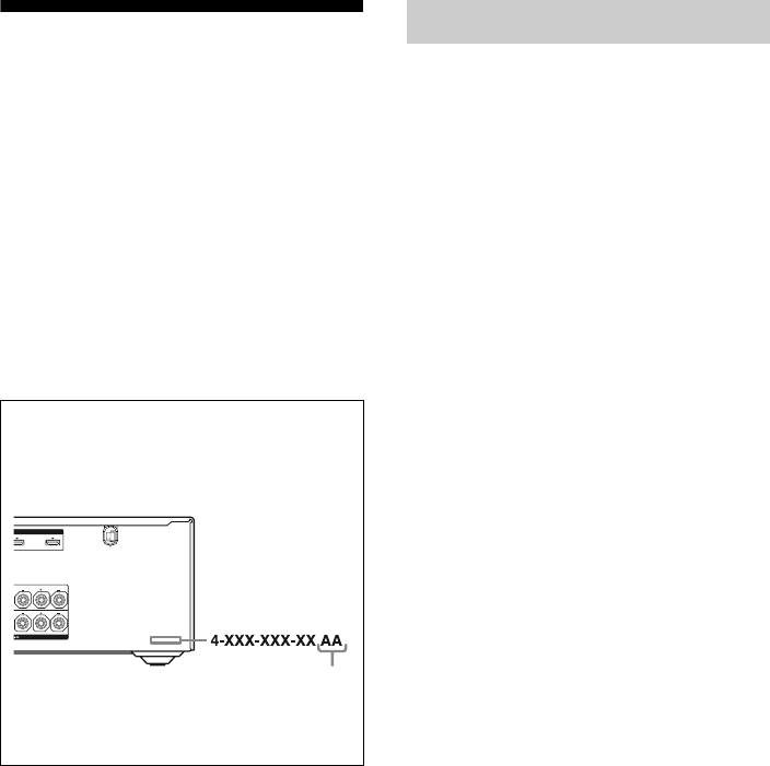
About area codes
The area code of the receiver you purchased is
shown on the lower right portion of the rear panel
(see the illustration below).
Any differences in operation, according to the area
code, are clearly indicated in the text, for example,
“Models of area code AA only”.
LR
OUT
FRONT A
LR
SURROUND
Area code
On copyrights

5US
The Bluetooth word mark and logos are owned by
the Bluetooth SIG, Inc. and any use of such marks
by Sony Corporation is under license.
Other trademarks and trade names are those of their
respective owners.
“M-crew Server” is a trademark of Sony
Corporation.
“x.v.Color” and “x.v.Color” logo are trademarks of
Sony Corporation.
“BRAVIA” is a trademark of Sony Corporation.
“S-AIR” and its logo are trademarks of Sony
Corporation.
DLNA and DLNA CERTIFIED are trademarks
and/or service marks of the Digital Living Network
Alliance.
The receiver is compatible with the S-AIR function,
which allows transmission of sound between S-AIR
products wirelessly.
The following S-AIR products can be used with the
receiver:
• Surround amplifier: You can enjoy surround
speaker sound wirelessly.
• S-AIR receiver: You can enjoy receiver sound in
another room.
These S-AIR products can be purchased as an option
(the S-AIR product lineup differs depending on the
area).
Notes or instructions for the surround amplifier or
S-AIR receiver in this operating instructions refer
only to when the surround amplifier or S-AIR
receiver is used.
For details on the S-AIR function, see “S-AIR
Operations” (page 97).
About the S-AIR function

6US
Table of Contents
Description and location of parts...................8
Getting Started
1: Installing speakers ...................................17
2: Connecting speakers ................................19
3: Connecting the TV ..................................21
4a: Connecting the audio components.........23
4b: Connecting the video components ........25
5: Connecting the antennas (aerials)............35
6: Preparing the receiver and the remote .....36
7: Displaying the GUI menu on the
TV screen................................................37
8: Selecting the front speaker system ..........38
9: Calibrating the appropriate speaker
settings automatically
(Auto Calibration) ..................................40
Guide to on-screen display operation ..........45
Playback
Enjoying sound/images from the
component connected to the receiver .....47
Enjoying sound/images from the
components connected to the
DIGITAL MEDIA PORT .......................49
Tuner Operations
Listening to FM/AM radio ..........................52
Presetting FM/AM radio stations ................54
Listening to Satellite Radio .........................55
Connecting the SIRIUS Satellite Radio ......56
Preparing to listen to the SIRIUS
Satellite Radio ........................................57
Selecting a channel of the SIRIUS
Satellite Radio ........................................58
Presetting SIRIUS Satellite Radio
channels ..................................................59
Restricting access to specific channels
(Parental Lock) .......................................60
Enjoying Surround Sound
Playing back with 2-channel sound ............ 63
Playing back with multi-channel
surround ................................................. 64
Enjoying a surround effect for
music/movie........................................... 67
Resetting sound fields to the initial
settings ................................................... 70
Amplifier Operations
Using the setting menu ............................... 70
Settings for the Auto Calibration
(Auto Calibration menu) ........................ 72
Setting for the speaker
(Speaker Settings menu) ........................ 73
Settings for the surround sound
(Surround Settings menu) ...................... 77
Settings for the EQ (EQ menu)................... 78
Settings for the audio
(Audio Settings menu) ........................... 78
Settings for the video
(Video Settings menu) ........................... 79
Settings for HDMI
(HDMI Settings menu) .......................... 81
Settings for the S-AIR
(S-AIR Settings menu)........................... 82
Operating without connecting to a TV ....... 82
“BRAVIA” Sync Features
What is “BRAVIA” Sync? .......................... 93
Preparing for the “BRAVIA” Sync ............. 94
Playing back components with one-touch
operation (One-Touch Play)................... 96
Enjoying the TV sound from the speakers
connected to the receiver
(System Audio Control)......................... 96
Turning off the receiver with the TV
(System Power Off) ............................... 97

7US
S-AIR Operations
About S-AIR products ................................ 97
Setting up an S-AIR product ....................... 99
Enjoying the system’s sound in another
room ..................................................... 104
Changing the channel
for better sound transmission ............... 105
Stabilizing S-AIR reception ...................... 106
Enjoying the S-AIR receiver while the
S-AIR main unit is in standby mode.... 107
Other Operations
Switching between digital and analog
audio (INPUT MODE) ........................ 108
Enjoying the sound/images from other
inputs.................................................... 109
Using the Sleep Timer............................... 111
Changing the brightness of the front
panel display (DIMMER) .................... 111
Enjoying the surround effect at low
volume levels (NIGHT MODE)........... 112
Recording using the receiver..................... 112
Using a bi-amplifier connection................ 113
Using the Remote
Operating each component using the
remote .................................................. 115
Programming the remote........................... 117
Clearing all the contents of the remote’s
memory ................................................ 121
Additional Information
Glossary .................................................... 122
Precautions ................................................ 125
Troubleshooting ........................................ 126
Specifications ............................................ 133
Index.......................................................... 135
8US
Description and location of parts
Front panel
MULTI CHANNEL DECODING
?/1
INPUT SELECTOR
MUTING
MASTER
VOLUME
SPEAKERS
PHONES 2 CH/
A.DIRECT A.F.D. MOVIE MUSIC INPUT MODE DIMMER DISPLAY
VIDEO 2 IN
VIDEO L AUDIO R
AUTO CAL MIC
68
4375
9q;qaqsqdqfqgqh
12
Name Function
A ?/1 (on/standby) Press to turn the receiver on
or off (page 36, 37, 54, 70).
BRemote sensor Receives signals from
remote commander.
CWhite lamp Lights up when the receiver
is on.
Lights off when the
receiver is off or the
“DIMMER” is set to
“70% DOWN”.
DMULTI
CHANNEL
DECODING lamp
Lights up when multi
channel audio signals are
decoded (page 128).
EDisplay The current status of the
selected component or a list
of selectable items appears
here (page 10).
Name Function
FMUTING Press to turn off the sound
temporarily.
Press MUTING again to
restore the sound (page 48,
126).
GINPUT
SELECTOR +/–
Press repeatedly to select
the input source to playback
(page 48, 108, 112).
HMASTER
VOLUME
Turn to adjust the volume
level of all speakers at the
same time (page 48, 126).
IVIDEO 2 IN
jacks
Connects to a portable
audio/video component
such as a camcorder or
video game (page 32, 48).

9US
Name Function
JAUTO CAL MIC
jack
Connects to the supplied
optimizer microphone for
the Auto Calibration
function (page 41).
KDISPLAY Press repeatedly to select
information displayed on
the display (page 88, 132).
LDIMMER Press repeatedly to adjust
the brightness of the display
(page 111).
MINPUT MODE Press to select the input
mode when the same
components are connected
to both digital and analog
jacks (page 108).
N2CH/A.DIRECT Press to select a sound field
(page 63, 64, 67).
A.F.D.
MOVIE
MUSIC
OSPEAKERS Press to select the front
speaker system (page 38).
PPHONES jack Connects to headphones
(page 127).
10US
About the indicators on the display
12 4 5 687 9
qh
qk qj q;
3
qa
qg qf qsqd
Name Function
ASW Lights up when subwoofer is
connected and the audio signal
is output from the
SUBWOOFER jack. While this
indicator lights up, the receiver
creates a subwoofer signal
based on the LFE signal in the
disc being played back or the
low frequency components of
the front channels.
BLFE Lights up when the disc being
played back contains an LFE
(Low Frequency Effect)
channel and the LFE channel
signal is actually being
reproduced.
CInput
indicators
COAX
OPT
HDMI
DMPORT
ANALOG
Light up to indicate the current
input.
Lights up when INPUT MODE
is set to “AUTO” and the source
signal is a digital signal being
input through the COAXIAL
jack (page 108).
Lights up when INPUT MODE
is set to “AUTO” and the source
signal is a digital signal being
input through the OPTICAL
jack (page 108).
The receiver recognizes a
component connected via an
HDMI IN jack.
The DIGITAL MEDIA PORT
adapter is connected and
“DMPORT” is selected.
No digital signal is being input.
When INPUT MODE is set to
“ANALOG” or when the
“Analog Direct” is being
selected, it also lights up.
Name Function
DDolby
Digital
Surround
indicators
D
D EX
D+
TrueHD
Lights up one of the respective
indicators when the receiver is
decoding the corresponding
Dolby Digital format signals.
Dolby Digital
Dolby Digital Surround EX
Dolby Digital Plus
Dolby TrueHD
Note
When playing a Dolby Digital
format disc, be sure that you
have made digital connections
and that INPUT MODE is set
to “AUTO” (page 108).
ENeural-THX Lights up when the receiver
applies Neural-THX
processing to input signals.
FDTS(-ES)
indicators
DTS
DTS 96/24
NEO:6
DTS-ES
Light up when DTS or DTS-
ES signals are input.
Lights up when the receiver is
decoding DTS signals.
Lights up when the receiver is
decoding DTS 96 kHz/24 bit
signals.
Lights up when DTS Neo:6
Cinema/Music decoder is
activated (page 66).
Lights up when the receiver is
decoding DTS-ES signals.
Note
When playing a DTS format
disc, be sure that you have
made digital connections and
that INPUT MODE is set to
“AUTO” (page 108).
11US
Name Function
GD.RANGE Lights up when dynamic range
compression is activated.
HSP A/SP B/
SP A+B
Lights up according to the front
speaker system used (page 38).
However, these indicators do not
light up if the speaker output is
turned off or if headphones are
connected.
ISLEEP Lights up when the Sleep Timer is
activated.
JA.DIRECT Lights up when “Analog Direct”
is selected.
KTu nin g
indicators
CAT
MEM
MONO
ST
SIRIUS
Lights up when the receiver tunes
in radio stations, or satellite radio
stations.
The category mode is selected
during the satellite radio
operation.
Lights up when a memory
function, such as Preset Memory
(page 54), etc., is activated.
Monaural broadcast
Stereo broadcast
The SiriusConnect Home tuner is
connected and “SR” is selected.
LS-AIR Lights up when the S-AIR
transmitter (not supplied) is
connected.
MDolby
Pro Logic
indicators
PL
PL II
PL IIx
Lights up one of the respective
indicators when the receiver
applies Dolby Pro Logic
processing to 2 channel signals in
order to output the center and
surround channel signals.
Dolby Pro Logic
Dolby Pro Logic II
Dolby Pro Logic IIx
Note
These indicators do not light up
when either the center speaker and
surround speaker is not connected.
NBI-AMP Lights up when “SB Assign” is set
to “BI-AMP” (page 113).
OEQ Lights up when the equalizer is
activated.
Name Function
PDTS-HD
indicators
DTS-HD
MSTR
DTS-HD HI
RES
Lights up one of the respective
indicators when the receiver is
decoding the corresponding
DTS-HD format signals.
DTS-HD Master Audio
DTS-HD High Resolution
Audio
QLPCM Lights up when Linear PCM
(Pulse Code Modulation)
signals are input.
RPlayback
channel
indicators
L
R
C
SL
SR
S
SBL
SBR
SB
The letters (L, C, R, etc.)
indicate the channels being
played back. The boxes around
the letters vary to show how the
receiver downmixes the source
sound (based on the speaker
settings).
Front Left
Front Right
Center (monaural)
Surround Left
Surround Right
Surround (monaural or the
surround components obtained
by Pro Logic processing)
Surround Back Left
Surround Back Right
Surround Back (the surround
back components obtained by
6.1 channel decoding)
Example:
Recording format (Front/
Surround): 3/2.1
Output channel: When “SP
Pattern” is set to “3/0.1”
(page 73, 85)
Sound Field: “A.F.D. Auto”
12US
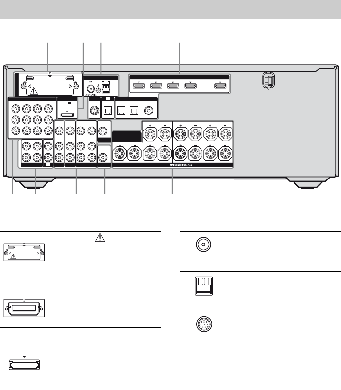
Rear panel
68
143
576
2
LR
VIDEO
OUT
MONITOR
L
R
DIGITAL
(ASSIGNABLE)
DC5V
0.7A MAX
HDMI
ANTENNA
DMPORT
IN 4
ASSIGNABLE (INPUT ONLY)
IN 3
IN 2
IN 3 IN 1 OUT
AM
Y
P
B
/
C
B
COMPONENT VIDEO
OUT IN
P
R
/
C
R
IN 2 IN 1 MONITOR
OUT
SA-CD/CD/CD-R
VIDEO 1
IN
TV
AUDIO
IN
VIDEO
IN
SAT
AUDIO
OUT
AUDIO
OUT
VIDEO
OUT
OPTICAL IN
AUDIO
IN
VIDEO
IN
SUBWOOFER
AUDIO
IN
VIDEO
IN
BD
LR
L
R
SPEAKERS
SAT IN BD IN DVD IN
OPTICAL
CENTER
FRONT A
COAXIAL
ASSIGNABLE (INPUT ONLY)
SURROUND BACK/
FRONT B/
BI-AMP
TV
SIRIUS
LR
SURROUND
(for AUDIO)
EZW-T100
AS-AIR (EZW-T100)
CAUTION
Please do not remove
the slot cover until
you want to install
the wireless
transmitter.
Connects to a
wireless transmitter
(not supplied) (page
99).
BDMPORT
DMPORT
jack
Connects to a Sony
DIGITAL MEDIA
PORT adapter
(page 23).
With slot cover
slot
CANTENNA section
FM
ANTENNA
jack
Connects to the FM
wire antenna (aerial)
supplied with this
receiver (page 35).
AM
ANTENNA
terminals
Connects to the AM
loop antenna (aerial)
supplied with this
receiver (page 35).
SIRIUS jack Connects to a
SiriusConnect Home
tuner (not supplied)
(page 56).
13US
* You can watch the selected input image when you
connect the MONITOR OUT or HDMI OUT jack
to a TV (page 21). You can operate this receiver
using a GUI (Graphical User Interface) if you
connect HDMI OUT jack or COMPONENT
VIDEO MONITOR OUT jacks to a TV (page 37).
DDIGITAL INPUT/OUTPUT section
OPTICAL
IN jacks
Connects to a BD
player, etc. (page
21, 26, 29, 30, 31).
COAXIAL
IN jack
HDMI IN/
OUT* jacks
Connects to a DVD
player, satellite
tuner, or a Blu-ray
disc player. The
image is output to a
TV or a projector
while the sound can
be output from a TV
or/and speakers
connected to this
receiver (page 21,
26).
ESPEAKERS section
Connects to
speakers (page 19).
FAUDIO INPUT/OUTPUT section
AUDIO IN/
OUT jacks
Connects to a Super
Audio CD player,
etc. (page 21, 23,
26).
AUDIO OUT
jack
Connects to
subwoofer (page
19).
GVIDEO/AUDIO INPUT/OUTPUT
section
AUDIO IN/
OUT jacks
Connects to a VCR,
Blu-ray disc player,
etc. (page 30, 31,
32).
VIDEO IN/
OUT* jacks
White (L)
Red (R)
Black
White (L)
Red (R)
Yellow
HCOMPONENT VIDEO INPUT/
OUTPUT section
Y, PB/CB,
PR/CR IN/
OUT* jacks
Connects to a BD
player, TV, satellite
tuner, etc. (page 21,
29, 30, 31).
Green
(Y)
Blue
(PB/CB)
Red
(PR/CR)
14US
You can use the supplied remote to operate the
receiver and to control the Sony audio/video
components that the remote is assigned to
operate.
You can also program the remote to control
non-Sony audio/video components. For
details, see “Programming the remote” (page
117).
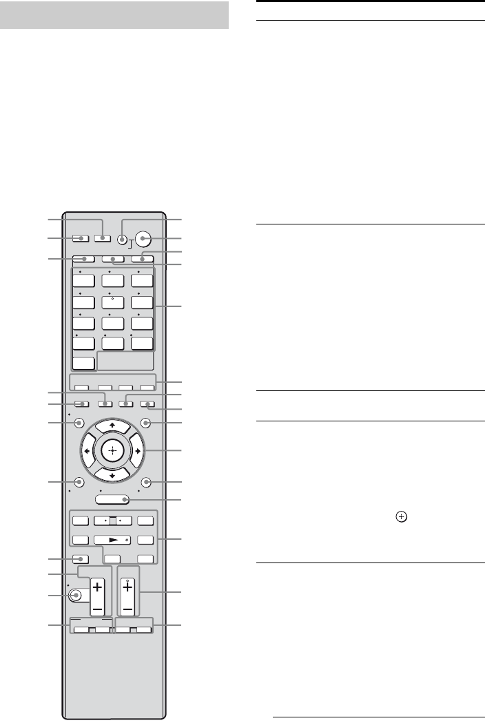
RM-AAP040
Remote commander
1 2 3
4 5 6
7 8 9
-/-- 0/10
ENT/MEM
2CH/
A.DIRECT A.F.D. MOVIE MUSIC
THEATER
SYSTEM STANDBY
RM SET UP
?/1
CLEAR
/
>10
SHIFT
TUNING – TUNING +
DISC SKIP D.TUNING
RESOLUTION
.
mM
>
Xx
MUTING
VIDEO 1 VIDEO 2 BD
SAT TV
HDMI 3HDMI 2HDMI 1
HDMI 4
SA-CD/
CD DMPORTTUNER
TV VOL
MASTER VOL
TV CH
PRESET
<
<
MENU
AV
?/1
F1 F2
TV INPUT
TOP MENU MENU
BD/DVD
WIDE
RETURN/
EXIT TOOLS/
OPTIONS
HOME
DISPLAY GUI MODE
O
DVD
INPUT
MODE SLEEP
NIGHT
MODE
TV AMP
– CATEGORY +
CATEGORY MODE
1
2
3
4
5
6
7
8
0
qs
qd
qf
qg
9
qh
qj
qk
ql
w;
wa
wd
wf
wh
ws
qa
wg
Name Function
AAV ?/1a)
(on/standby)
Press to turn on or off the
audio/video components that
the remote is programmed to
operate.
To turn the TV on or off, press
TV (D) and then press AV
?/1.
If you press ?/1 (B) at the
same time, it will turn off the
receiver and other components
(SYSTEM STANDBY).
Note
The function of the AV ?/1
switch changes automatically
each time you press the input
buttons (E).
B?/1
(on/standby)
Press to turn the receiver on or
set it to the standby mode.
To turn off all components,
press ?/1 and AV ?/1 (A) at
the same time (SYSTEM
STANDBY).
Saving the power in
standby mode.
When “Ctrl for HDMI” is set
to “OFF” (page 94) and
“S-AIR Stby” is set to “OFF”
(page 107).
CAMP Press to enable the receiver
operation (page 82).
DTV Press to light up the button. It
changes the remote key
function to activate the buttons
with yellow printing. It also
activate the DISPLAY (U),
TOOLS/OPTIONS (K),
HOME (L), RETURN/EXIT
O (T), (J), and V/v/
B/b (J) buttons to perform
menu operations for Sony TVs
only.
EInput buttons
(SATb))
Press one of the buttons to
select the component you want
to use. When you press any of
the input buttons, the receiver
turns on. The buttons are
factory assigned to control
Sony components (page 48).
You can program the remote to
control non-Sony components
following the steps in
“Programming the remote” on
page 117.
15US
Name Function
Numeric
buttonsa)
(number 5b))
Press SHIFT (X), then press
numeric buttons to
– preset/tune to preset stations.
– select track numbers of the
CD player, DVD player,
Blu-ray disc player or MD
deck, etc. Press 0/10 to select
track number 10.
– select channel numbers of
the VCR or satellite tuner,
etc.
Press TV (D) and then press
the numeric buttons to select
the TV channels.
ENT/MEMa) Press SHIFT (X), then press
ENT/MEM to
– enter the value after selecting
a channel, disc or track using
the numeric buttons.
– store a station during tuner
operation.
To enter the value of Sony TV,
press TV (D) and then press
ENT/MEM.
CLEARa) Press SHIFT (X), then press
CLEAR to
– clear a mistake when you
press the incorrect numeric
button.
– return to continuous
playback, etc. of the satellite
tuner or DVD player.
-/--a) Press SHIFT (X), then press
-/-- to select the channel entry
mode, either one or two digit
of the VCR or satellite tuner.
To select the channel entry
mode of the TV, press TV (D)
and then press -/--.
>10a) Press SHIFT (X), then press
>10 to
– select track numbers over 10
of the CD player, DVD
player, Blu-ray disc player or
MD deck, etc.
– select channel numbers of
the Digital CATV terminal.
F2CH/
A.DIRECT
Press to select a sound field
(page 63, 64, 67).
A.F.D.
MOVIE
MUSIC
Name Function
GSLEEP Press to activate the Sleep
Timer function and the
duration which the receiver
turns off automatically
(page 111).
HNIGHT MODE Press to activate the NIGHT
MODE function (page 112).
IGUI MODE Press to display the GUI menu
on the TV screen.
J
V/v/B/ba)
Press V/v/B/b to select the
menu items.
Then press to enter the
selection.
KTOOLS/
OPTIONSa) Press to display and select
items from the option menus
for receiver, DVD player,
Blu-ray disc player or satellite
tuner.
Press TV (D) and then press
TOOLS/OPTIONS to display
the options of Sony TV.
LHOMEa),
MENUa) Press to display the menu to
operate the audio/video
components.
To display the menus of Sony
TV, press TV (D) and then
press HOME.
M./>a)
m/Ma)
Na)b)
Xa)
xa)
Press to operate the DVD
player, Blu-ray disc player,
CD player, MD deck, tape
deck, or component
connected to the DIGITAL
MEDIA PORT adapter, etc.
/a) Press to replay the previous
scene or fast forward the
current scene of the DVD
player or Blu-ray disc player,
etc.
TUNING +/–a) Press to scan a station.
CATEGORY
MODE
Press to select the category
mode for satellite tuner (page
58, 92).
CATEGORY
+/–
Press to select a category for
satellite tuner (page 59, 92).
D.TUNING Press to enter direct tuning
mode (page 53, 91).
NTV CH +b)/–a) Press TV (D) and then press
TV CH +/– to select preset
TV channels.
,
a)
<
<
continued
16US
a)See the table on page 116 for information on the
buttons that you can use to control each
component.
b)The number 5/SAT, TV CH +/PRESET + and N
buttons have tactile dots. Use the tactile dots as
references when operating the receiver.
Notes
• Some functions explained in this section may not
work depending on the model.
• The above explanation is intended to serve as an
example only. Therefore, depending on the
component, the above operation may not be
possible or may operate differently than described.
Name Function
PRESET
+b)/–a) Press to
– select preset stations.
– select preset channels of the
VCR, satellite tuner,
Blu-ray disc player, DVD
player, LD player, DVD/
VHS COMBO, or DVD/
HDD COMBO.
OF1a), F2a) Press BD or DVD (E), then
press F1 or F2 to select a
component.
• DVD/HDD COMBO
F1: HDD
F2: DVD disc, Blu-ray disc
• DVD/VHS COMBO
F1: DVD disc, Blu-ray disc
F2: VHS
PBD/DVD TOP
MENUa) Press to display the menu or
on-screen guide of the DVD
player, Blu-ray disc player,
PSX or DVD/VHS COMBO
on the TV screen. Then, use
V/v/B/b (J) and (J) to
perform menu operations.
BD/DVD
MENUa) Press to display the menu of
the DVD player or Blu-ray
disc player on the TV screen.
Then, use V/v/B/b (J) and
(J) to perform menu
operations.
TV INPUTa) Press TV (D) and then press
TV INPUT to select the input
signal (TV input or video
input).
WIDEa) Press TV (D) and then press
WIDE repeatedly to select the
wide picture mode.
QMUTINGa) Press to turn off the sound
temporarily. Press the button
again to restore the sound.
To mute the sound of the TV,
press TV (D) and then press
MUTING.
RTV VOL +/–a) Press TV (D) and then press
TV VOL +/– to adjust the TV
volume level.
MASTER
VOL +/–a) Press to adjust the volume
level of all speakers at the
same time.
SDISC SKIPa) Press to skip disc when using
a multi-disc changer.
Name Function
TRETURN/
EXIT Oa) Press to
– return to the previous menu.
– exit the menu while the
menu or on-screen guide of
the VCD player, DVD
player, etc. is displayed on
the TV screen.
To return to the previous
menu of Sony TV, press TV
(D) and then press
RETURN/EXIT O.
UDISPLAYa) Press to display the current
status of or information on
components connected to the
receiver.
Note
In the GUI MODE, press the
button to display the menu on
the TV screen.
VRESOLUTION Press repeatedly to change the
resolution of signals output
from the HDMI OUT or
COMPONENT VIDEO
MONITOR OUT jack
(page 79).
WINPUT MODE Press to select the input mode
when the same components
are connected to both digital
and analog jacks (page 108).
XSHIFT Press to light up the button. It
changes the remote button
function to activate the
buttons with pink printing.
YTHEATER Press to turn the Theater mode
on and off when connecting
the receiver to products
featuring “BRAVIA” Sync.
ZRM SET UP Press to set up the remote.
17US
Getting Started
1: Installing speakers
This receiver allows you to use a 7.1 channel
system (7 speakers and one subwoofer).
To fully enjoy theater-like multi channel
surround sound requires five speakers (two
front speakers, a center speaker, and two
surround speakers) and a subwoofer (5.1
channel).
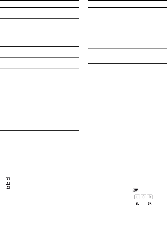
Example of a 5.1 channel
speaker system configuration
AFront speaker (left)
BFront speaker (right)
CCenter speaker
DSurround speaker (left)
ESurround speaker (right)
HSubwoofer
You can enjoy high fidelity reproduction of
DVD or Blu-ray disc software recorded sound
in the Surround EX format if you connect one
additional surround back speaker (6.1 channel
system) or two surround back speakers (7.1
channel system).
Example of a 7.1 channel
speaker system configuration
AFront speaker (left)
BFront speaker (right)
CCenter speaker
DSurround speaker (left)
ESurround speaker (right)
FSurround back speaker (left)
GSurround back speaker (right)
HSubwoofer
Getting Started
Enjoying a 5.1/7.1 channel
system
continued
18US
Tips
• When you connect a 7.1 channel speaker system,
the angle A should be the same.
• When you connect a 6.1 channel speaker system,
place the surround back speaker behind the
listening position.
• Since the subwoofer does not emit highly
directional signals, you can place it wherever you
want.
19US
Getting Started
2: Connecting speakers
Before connecting cords, be sure to disconnect the AC power cord (mains lead).
AFront speaker A (left)
BFront speaker A (right)
CCenter speaker
DSurround speaker (left)
ESurround speaker (right)
FSurround back speaker (left)a)b)c)
GSurround back speaker (right)a)b)c)
HSubwooferd)
VIDEO
OUT
MONITOR
DIGITAL
(ASSIGNABLE)
C
5V
7
A MAX
HDMI
ANTENNA
M
PORT
IN 4 IN 2
IN 3
AM
VIDEO 1
AUDIO
OUT
VIDEO
OUT
OPTICAL IN
AUDIO
IN
VIDEO
IN
AUDIO
IN
VIDEO
IN
BD
L
R
SAT IN BD IN DVD IN
OPTICAL COAXIAL
TV
SIRIUS
AUDIO
OUT
SUBWOOFER
LRLR
FRONT A
SURROUND BACK/
FRONT B/
BI-AMP
R
13/32 in.
(10 mm)
CENTER
L
SURROUND
SPEAKERS
ASSIGNABLE (INPUT ONLY)
IN 1 OUT
(for AUDIO)
H
AB
B
FG
AMonaural audio cord (not supplied)
BSpeaker cord (not supplied)
E
B
CD
A
continued
20US
a)If you connect only one surround back speaker,
connect it to the SPEAKERS SURROUND
BACK/FRONT B/BI-AMP L terminals.
b)If you are not using surround back speaker, and
you have an additional front speaker system,
connect the additional front speaker system to the
SPEAKERS SURROUND BACK/FRONT B/
BI-AMP terminals. Set “SB Assign” to “Speaker
B” in the Speaker Settings menu (page 73).
You can select the front speaker system you want
to use with SPEAKERS on the front panel
(page 38).
c)If you are not using surround back speakers, you
can connect the front speakers to the SPEAKERS
SURROUND BACK/FRONT B/BI-AMP
terminals using a bi-amplifier connection
(page 113).
Set “SB Assign” to “BI-AMP” in the Speaker
Settings menu (page 73).
d)When you connect a subwoofer with an auto
standby function, turn off the function when
watching movies. If the auto standby function is
set to on, it turns to standby mode automatically
based on the level of the input signal to a
subwoofer, then sound may not be output.
Note
Before connecting the AC power cord (mains lead),
make sure that metallic wires of the speaker cords
are not touching each other between the
SPEAKERS terminals.
21US
Getting Started
3: Connecting the TV
You can watch the selected input image when
you connect the HDMI OUT or MONITOR
OUT jack to a TV. You can operate this
receiver using a GUI (Graphical User
Interface) if you connect HDMI OUT jack or
COMPONENT VIDEO MONITOR OUT
jacks to a TV.
It is not necessary to connect all the cables.
Connect audio and video cords according to
the jacks of your components.
Before connecting cords, be sure to disconnect
the AC power cord (mains lead).
LR
L
R
DIGITAL
(ASSIGNABLE)
DC5V
0.7A MAX
ANTENNA
DMPORT
AM
OUT IN
SA-CD/CD/CD-R
VIDEO 1TV
AUDIO
IN
VIDEO
IN
SAT
AUDIO
OUT
AUDIO
OUT
VIDEO
OUT
OPTICAL IN
AUDIO
IN
VIDEO
IN
SUBWOOFER
AUDIO
IN
VIDEO
IN
BD
LR
L
R
SPEAKERS
SAT IN BD IN DVD IN
OPTICAL
CENTER
FRONT A
COAXIAL
SURROUND BACK/
FRONT B/
BI-AMP
TV
SIRIUS
LR
SURROUND
VIDEO
OUT
MONITOR
IN
(for AUDIO)
EZW-T100
Y
P
B
/
C
B
P
R
/
C
R
IN 2 IN 1 MONITOR
OUT
ASSIGNABLE (INPUT ONLY)
HDMI
IN 4
ASSIGNABLE (INPUT ONLY)
IN 2
IN 3 IN 1 OUT
IN 3
COMPONENT VIDEO
TV
AB
AComponent video cord (not supplied)
BVideo cord (not supplied)
COptical digital cord (not supplied)
DAudio cord (not supplied)
EHDMI cable (not supplied)
Sony recommends that you use an HDMI-authorized cable or Sony HDMI cable.
Video signals
CD E
Audio signals Audio/video signals
continued
22US
Notes
• Be sure to turn on the receiver when the video and
audio of a playback component are being output to
a TV via the receiver. If the power supply of the
receiver is not turned on, neither video nor audio is
transmitted.
• Connect image display components such as a TV
monitor or a projector to the HDMI OUT or
MONITOR OUT jack on the receiver. You may
not be able to record, even if you connect recording
components.
• Depending on the status of the connection between
the TV and the antenna (aerial), the image on the
TV screen may be distorted. In this case, place the
antenna (aerial) farther away from the receiver.
• When connecting optical digital cords, insert the
plugs straight in until they click into place.
• Do not bend or tie optical digital cords.
Tips
• The receiver has a video conversion function. For
details, see “Function for conversion of video
signals” (page 33).
• The sound of the TV is output from the speakers
connected to the receiver if you connect the audio
output jack of the TV to the TV IN jacks of the
receiver. In this configuration, set the sound output
jack of the TV to “Fixed” if it can be switched
between either “Fixed” or “Variable”.
23US
Getting Started
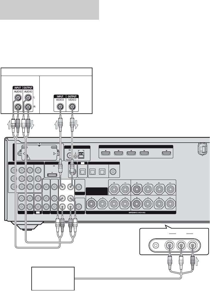
4a: Connecting the audio components
The following illustration shows how to
connect a Super Audio CD player, CD player,
CD recorder and DIGITAL MEDIA PORT
adapter. Before connecting cords, be sure to
disconnect the AC power cord (mains lead).
After connecting your audio component,
proceed to “4b: Connecting the video
components” (page 25) or “5: Connecting the
antennas (aerials)” (page 35).
Connecting audio components
LR
VIDEO
OUT
MONITOR
DIGITAL
(ASSIGNABLE)
HDMI
ANTENNA
IN 4
ASSIGNABLE (INPUT ONLY)
IN 3
IN 2
IN 3 IN 1 OUT
AM
Y
P
B
/
C
B
COMPONENT VIDEO
P
R
/
C
R
IN 2 IN 1 MONITOR
OUT
VIDEO 1
IN
TV
AUDIO
IN
VIDEO
IN
SAT
AUDIO
OUT
AUDIO
OUT
VIDEO
OUT
OPTICAL IN
AUDIO
IN
VIDEO
IN
SUBWOOFER
AUDIO
IN
VIDEO
IN
BD
LR
L
R
SPEAKERS
SAT IN BD IN DVD IN
OPTICAL
CENTER
FRONT A
COAXIAL
ASSIGNABLE (INPUT ONLY)
SURROUND BACK/
FRONT B/
BI-AMP
TV
SIRIUS
LR
SURROUND
R
SA-CD/CD/CD-R
DC5V
0.7A MAX
DMPORT
(for AUDIO)
EZW-T100
L
OUT IN
Super Audio CD player,
CD player, CD recorder
DIGITAL MEDIA
PORT adapter
AAudio cord (not supplied)
A
continued
24US
Notes on connecting DIGITAL
MEDIA PORT adapter
• Do not connect or disconnect the DIGITAL
MEDIA PORT adapter while the receiver is
turned on.
• Be sure to make DMPORT connections
firmly, insert the connector straight in.
• As the connector of the DIGITAL MEDIA
PORT adapter is fragile, be sure to handle
with care when placing or moving the
receiver.
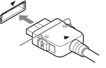
• When connecting the DIGITAL MEDIA
PORT adapter, be sure the connector is
inserted with the arrow mark facing towards
the arrow mark on the DMPORT jack. To
detach the DIGITAL MEDIA PORT
adapter, press and hold A and then pull out
the connector.
A
25US
Getting Started
4b: Connecting the video components
This section describes how to connect your
video components to this receiver. Before you
begin, see “Component to be connected”
below for the pages which describe how to
connect each component. Before connecting
cords, be sure to disconnect the AC power
cord (mains lead).
After connecting all your components,
proceed to “5: Connecting the antennas
(aerials)” (page 35).
Component to be connected
If you want to connect several
digital components, but cannot
find an unused input
See “Enjoying the sound/images from other
inputs” (page 109).
The image quality depends on the connecting
jack. See the illustration that follows. Select
the connection according to the jacks on your
components.
Note
Be sure to turn on the receiver when the video and
audio of a playback component are being output to a
TV via the receiver. If the power supply of the
receiver is not turned on, neither video nor audio is
transmitted.
Converting video signals
This receiver is equipped with a function for
up-converting video signals. For details, see
“Function for conversion of video signals”
(page 33).
How to connect your
components
Component Page
TV 21
With HDMI jack 26
DVD player 29
Blu-ray disc player 30
Satellite tuner, Set-top box 31
DVD recorder, VCR 32
Camcorder, video game, etc. 32
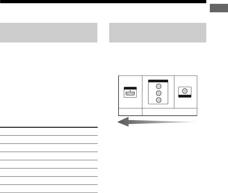
Video input/output jacks to be
connected
HDMI
VIDEO
COMPONENT VIDEO
Y
P
B
/
C
B
P
R
/
C
R
Digital Analog
High quality image

26US
HDMI is the abbreviated name for High-
Definition Multimedia Interface. It is an
interface which transmits video and audio
signals in digital format.
Sony recommends that you connect
components to the receiver using an HDMI
cable.
With HDMI, you can easily enjoy both high
quality sound and high quality images.
However, it is necessary to connect
the audio output of the TV to the
audio input of the receiver using an
optical digital cord to listen to the
TV multi channel surround sound
broadcasting from the receiver.
By connecting Sony “BRAVIA” Sync
compatible components using HDMI cables,
““BRAVIA” Sync Features” makes
operations simpler (page 93).
Notes
• Be sure to change the factory setting of the HDMI
1–4 input button on the remote so that you can use
the button to control your components. For details,
see “Programming the remote” (page 117).
• You can also rename the HDMI input so that it can
be displayed on the receiver’s display. For details,
see “Naming the input (Name Input)” (page 49).
HDMI features
• A digital audio signals transmitted by HDMI
can be output from the speakers connected to
the receiver. This signal supports Dolby
Digital, DTS, and Linear PCM.
• The receiver can receive Multi Linear PCM
(up to 8 channels) with a sampling frequency
of 192 kHz or less with an HDMI
connection.
• Analog video signals input to the VIDEO
jack or COMPONENT VIDEO jacks can be
up-converted as HDMI signals. Audio
signals are not output from an HDMI OUT
jack when the image is converted.
• This receiver supports High Bitrate Audio
(DTS-HD Master Audio, Dolby TrueHD),
Deep Color and x.v.Color transmission,
extended by HDMI version 1.3.
• This receiver supports the Control for HDMI
function. For details, see ““BRAVIA” Sync
Features” (page 93).
• HDMI 3 input has a better sound quality.
When you need a higher sound quality,
connect your component to the HDMI IN 3
(for AUDIO) jack and select HDMI 3 as
input.
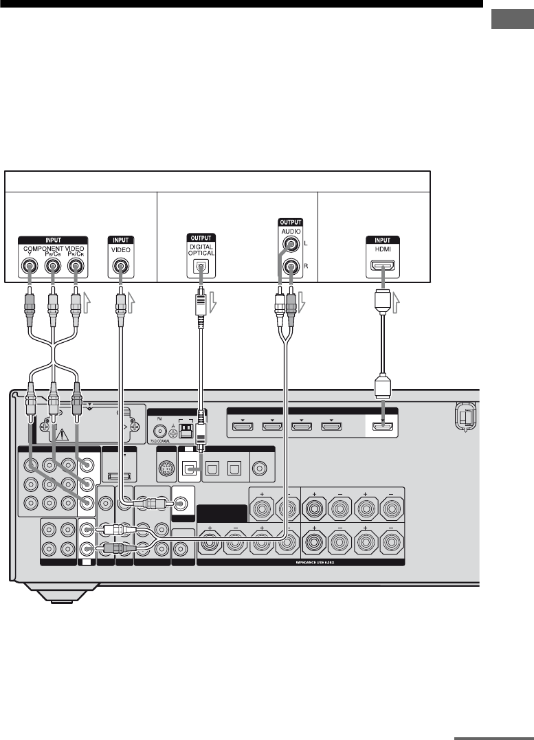
Connecting components with
HDMI jacks
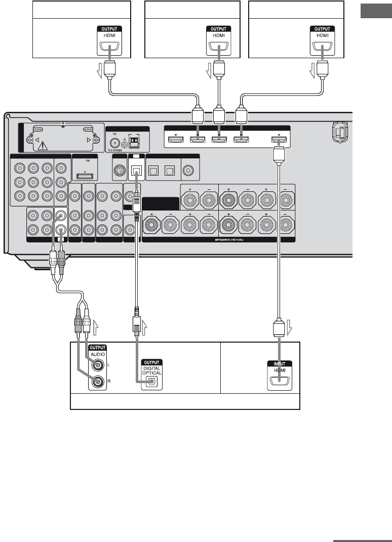
27US
Getting Started
a)Connect at least one of the audio cords (B or C).
LR
VIDEO
OUT
MONITOR
L
R
DIGITAL
(ASSIGNABLE)
DC5V
0.7A MAX
HDMI
ANTENNA
DMPORT
IN 4
ASSIGNABLE (INPUT ONLY)
IN 3
IN 2
IN 3 IN 1 OUT
AM
Y
P
B
/
C
B
COMPONENT VIDEO
OUT IN
P
R
/
C
R
IN 2 IN 1 MONITOR
OUT
VIDEO 1
AUDIO
IN
VIDEO
IN
SAT
AUDIO
OUT
AUDIO
OUT
VIDEO
OUT
AUDIO
IN
VIDEO
IN
SUBWOOFER
AUDIO
IN
VIDEO
IN
BD
LR
L
R
SPEAKERS
SAT IN BD IN DVD IN
OPTICAL
CENTER
FRONT A
COAXIAL
ASSIGNABLE (INPUT ONLY)
SURROUND BACK/
FRONT B/
BI-AMP
TV
SIRIUS
LR
SURROUND
IN
EZW-T100
TV
OPTICAL IN
SA-CD/CD/CD-R
(for AUDIO)
A
AHDMI cable (not supplied)
Sony recommends that you use an HDMI-authorized cable or Sony HDMI cable.
BAudio cord (not supplied)a)
COptical digital cord (not supplied)a)
DVD player
Audio/video
signals
Blu-ray disc player
Audio/video
signals
A
A
TV, projector, etc.
Audio/video
signals
Audio/video
signals
Satellite tuner, Set-top box
A
C
Audio signals
B
continued
28US
Notes on connecting cables
• We recommend that you use an HDMI cable
with the HDMI logo (made by Sony) for the
HDMI jack corresponding to high speed (an
HDMI version 1.3a, category 2 cable) when
you view images or listen to sound during a
Deep Color transmission or when you watch
a video image of 1080p or higher.
• We do not recommend using an HDMI-DVI
conversion cable. When you connect an
HDMI-DVI conversion cable to a DVI-D
component, the sound and/or the image may
not be output. Connect other audio cords or
digital connecting cords, then set “Input
Assign” in the Input Option menu when the
sound is not output correctly.
Notes on HDMI connections
• An audio signal input to the HDMI IN jack
is output from the SPEAKERS jacks and
HDMI OUT jack. It is not output from any
other audio jacks.
• A video signal input to the HDMI IN jack
can only be output from the HDMI OUT
jack. The video input signals cannot be
output from the VIDEO OUT jacks or
MONITOR OUT jacks.
• The audio and video signals of HDMI input
are not output from the HDMI OUT jack
while the receiver menu is displayed.
• When you want to listen to the sound from
the TV speaker, set “Audio Out” to
“TV+AMP” in the HDMI Settings menu
(page 81). If you cannot play back multi
channel audio source, set to “AMP”.
However, the sound will not output from the
TV speaker.
• DSD signals of Super Audio CD are not
input and output.
• Be sure to turn on the receiver when the
video and audio of a playback component
are being output to a TV via the receiver. If
the power supply of the receiver is not
turned on, neither video nor audio is
transmitted.
• Audio signals (sampling frequency, bit
length, etc.) transmitted from an HDMI jack
may be suppressed by the connected
component. Check the setup of the
connected component if the image is poor or
the sound does not come out of a component
connected via the HDMI cable.
• Sound may be interrupted when the
sampling frequency, the number of channels
or audio format of audio output signals from
the playback component is switched.
• When the connected component is not
compatible with copyright protection
technology (HDCP), the image and/or the
sound from the HDMI OUT jack may be
distorted or may not be output.
In this case, check the specification of the
connected component.
• You can enjoy High Bitrate Audio (DTS-HD
Master Audio, Dolby TrueHD), multi
channel Linear PCM only with an HDMI
connection.
• Set the image resolution of the playback
component to more than 720p to enjoy High
Bitrate Audio (DTS-HD Master Audio,
Dolby TrueHD).
• The image resolution of playback
component may need certain settings be
made before you can enjoy multi channel
Linear PCM. Refer to the operating
instructions of the playback component.
• Not every HDMI component supports all
functions that are defined by the specified
HDMI version. For example, components
that support HDMI, version 1.3a, may not
support Deep Color.
• Refer to the operating instructions of each
connected component for details.
29US
Getting Started
The following illustration shows how to
connect a DVD player.
It is not necessary to connect all the cords.
Connect audio and video cords according to
the jacks of your components.
Notes
• The COMPONENT VIDEO IN 2 jacks have been
assigned to the DVD player. If you connect your
DVD player to the COMPONENT VIDEO IN 1 or
IN 3 jacks, set “Input Assign” in the Input Option
menu (page 109).
• To input multi channel digital audio from the DVD
player, set the digital audio output setting on the
DVD player. Refer to the operating instructions
supplied with the DVD player.
• When connecting optical digital cords, insert the
plugs straight in until they click into place.
• Do not bend or tie optical digital cords.
Tip
All the digital audio jacks are compatible with
32 kHz, 44.1 kHz, 48 kHz, and 96 kHz sampling
frequencies.
* When you connect a component equipped with an
OPTICAL jack, set “Input Assign” in the Input
Option menu.
Connecting a DVD player
LR
VIDEO
OUT
MONITOR
L
R
DC5V
0.7A MAX
HDMI
ANTENNA
DMPORT
IN 4
ASSIGNABLE (INPUT ONLY)
IN 2
IN 3 IN 1 OUT
AM
OUT IN
SA-CD/CD/CD-R
VIDEO 1
IN
TV
AUDIO
IN
VIDEO
IN
SAT
AUDIO
OUT
AUDIO
OUT
VIDEO
OUT
OPTICAL IN
AUDIO
IN
VIDEO
IN
SUBWOOFER
AUDIO
IN
VIDEO
IN
BD
LR
L
R
SPEAKERS
CENTER
FRONT A
SURROUND BACK/
FRONT B/
BI-AMP
TV
SIRIUS
LR
SURROUND
SAT IN BD IN DVD IN
OPTICAL COAXIAL
(for AUDIO)
EZW-T100
IN 3
Y
P
B
/
C
B
P
R
/
C
R
OUT
ASSIGNABLE (INPUT ONLY)
COMPONENT VIDEO
IN 2 IN 1 MONITOR
DIGITAL
(ASSIGNABLE)
DVD player
AB
AComponent video cord (not supplied)
BOptical digital cord (not supplied)
CCoaxial digital cord (not supplied)
C
Video signals Audio signals
30US
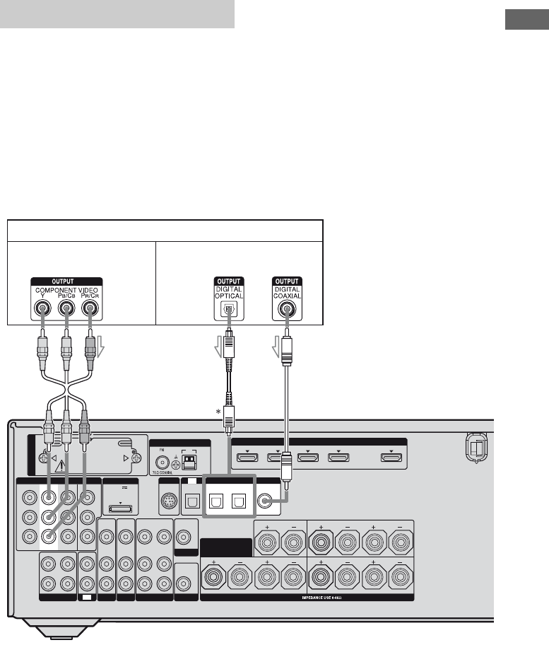
The following illustration shows how to
connect a Blu-ray disc player.
It is not necessary to connect all the cords.
Connect audio and video cords according to
the jacks of your components.
Notes
• The COMPONENT VIDEO IN 1 jacks have been
assigned to the Blu-ray disc player. If you connect
your Blu-ray disc player to the COMPONENT
VIDEO IN 2 or IN 3 jacks, set “Input Assign” in
the Input Option menu (page 109).
• To input multi channel digital audio from the Blu-
ray disc player, set the digital audio output setting
on the Blu-ray disc player. Refer to the operating
instructions supplied with the Blu-ray disc player.
• When connecting optical digital cords, insert the
plugs straight in until they click into place.
• Do not bend or tie optical digital cords.
Tip
All the digital audio jacks are compatible with
32 kHz, 44.1 kHz, 48 kHz, and 96 kHz sampling
frequencies.
* When you connect a component equipped with an
COAXIAL jack, set “Input Assign” in the Input
Option menu.
Connecting a Blu-ray disc player
LR
VIDEO
OUT
MONITOR
L
R
DC5V
0.7A MAX
ANTENNA
DMPORT
IN 4 IN 2
IN 3 IN 1 OUT
AM
OUT IN
SA-CD/CD/CD-R
VIDEO 1
IN
TV
AUDIO
IN
VIDEO
IN
SAT
AUDIO
OUT
AUDIO
OUT
VIDEO
OUT
OPTICAL IN
AUDIO
IN
VIDEO
IN
SUBWOOFER
LR
L
R
SPEAKERS
CENTER
FRONT A
SURROUND BACK/
FRONT B/
BI-AMP
TV
SIRIUS
LR
SURROUND
AUDIO
IN
BD
(for AUDIO)
EZW-T100
SAT IN BD IN
Y
P
B
/
C
B
P
R
/
C
R
MONITOR
OUT
ASSIGNABLE (INPUT ONLY)
IN 3
COMPONENT VIDEO
IN 2 IN 1
VIDEO
IN
OPTICAL
ASSIGNABLE (INPUT ONLY)
(ASSIGNABLE)
DIGITAL
COAXIAL
DVD IN
HDMI
Blu-ray disc player
A
AComponent video cord (not supplied)
BVideo cord (not supplied)
CAudio cord (not supplied)
DOptical digital cord (not supplied)
ECoaxial digital cord (not supplied)
CB
Video signals Audio signals
DE
31US
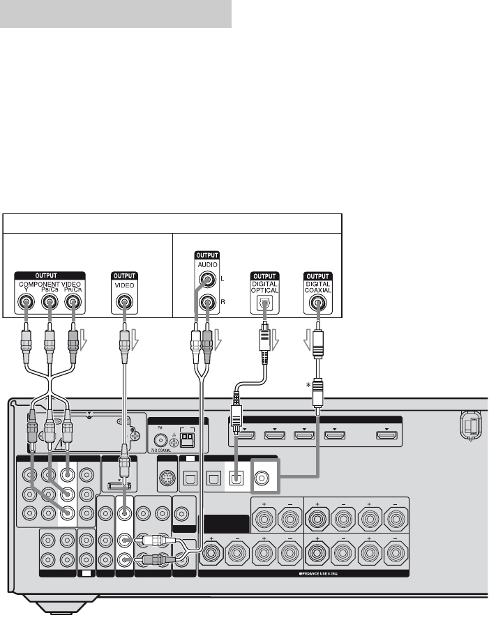
Getting Started
The following illustration shows how to
connect a satellite tuner or set-top box.
It is not necessary to connect all the cords.
Connect audio and video cords according to
the jacks of your components.
Notes
• The COMPONENT VIDEO IN 3 jacks have been
assigned to the satellite tuner. If you connect your
satellite tuner to the COMPONENT VIDEO IN 1
or IN 2 jacks, set “Input Assign” in the Input
Option menu (page 109).
• When connecting optical digital cords, insert the
plugs straight in until they click into place.
• Do not bend or tie optical digital cords.
Tip
All the digital audio jacks are compatible with
32 kHz, 44.1 kHz, 48 kHz, and 96 kHz sampling
frequencies.
Connecting a satellite tuner,
set-top box
LR
VIDEO
OUT
MONITOR
L
R
DC5V
0.7A MAX
HDMI
ANTENNA
DMPORT
IN 4
ASSIGNABLE (INPUT ONLY)
IN 2
IN 3 IN 1 OUT
AM
OUT IN
OUT
SA-CD/CD/CD-R
VIDEO 1
IN
TV
AUDIO
OUT
AUDIO
OUT
VIDEO
OUT
OPTICAL IN
AUDIO
IN
VIDEO
IN
SUBWOOFER
AUDIO
IN
VIDEO
IN
BD
LR
L
R
SPEAKERS
CENTER
FRONT A
SURROUND BACK/
FRONT B/
BI-AMP
TV
SIRIUS
LR
SURROUND
AUDIO
IN
DIGITAL
(ASSIGNABLE)
SAT IN BD IN DVD IN
OPTICAL COAXIAL
(for AUDIO)
EZW-T100
Y
P
B
/
C
B
P
R
/
C
R
MONITOR
ASSIGNABLE (INPUT ONLY)
IN 3
COMPONENT VIDEO
IN 2 IN 1
VIDEO
IN
SAT
BA
Video signals Audio signals
C
Satellite tuner, Set-top box
D
AComponent video cord (not supplied)
BVideo cord (not supplied)
COptical digital cord (not supplied)
DAudio cord (not supplied)
32US
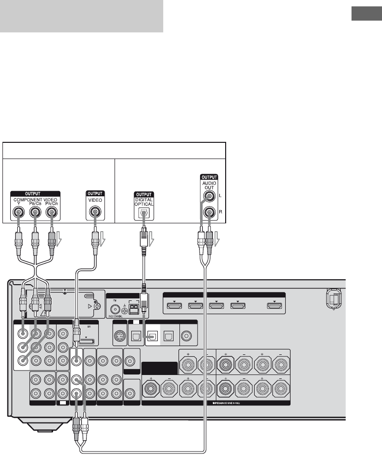
The following illustration shows how to
connect a component which has analog jacks
such as a DVD recorder, VCR, etc.
It is not necessary to connect all the cords.
Connect audio and video cords according to
the jacks of your components.
Notes
• Be sure to change the factory setting of the VIDEO
1 input button on the remote so that you can use the
button to control your DVD recorder. For details,
see “Programming the remote” (page 117).
• You can also rename the VIDEO 1 input so that it
can be displayed on the TV screen and display. For
details, see “Naming the input (Name Input)”
(page 49).
Connecting components with
analog video and audio jack
LR
VIDEO
OUT
MONITOR
L
R
DIGITAL
(ASSIGNABLE)
DC5V
0.7A MAX
HDMI
ANTENNA
DMPORT
IN 4
ASSIGNABLE (INPUT ONLY)
IN 3
IN 2
IN 3 IN 1 OUT
AM
Y
P
B
/
C
B
COMPONENT VIDEO
OUT IN
P
R
/
C
R
IN 2 IN 1 MONITOR
OUT
SA-CD/CD/CD-R
IN
TV
AUDIO
IN
VIDEO
IN
SAT
AUDIO
OUT
OPTICAL IN
AUDIO
IN
VIDEO
IN
BD
LR
SPEAKERS
SAT IN BD IN DVD IN
OPTICAL
CENTER
FRONT A
COAXIAL
ASSIGNABLE (INPUT ONLY)
SURROUND BACK/
FRONT B/
BI-AMP
TV
SIRIUS
LR
SURROUND
AUDIO
OUT
AUDIO
IN
L
R
(for AUDIO)
EZW-T100
VIDEO 2 IN
VIDEO L AUDIO R
AUTO CAL MIC
VIDEO 1
VIDEO
OUT
VIDEO
IN
SUBWOOFER
DVD recorde r, VCR
A
To the VIDEO 2 IN jacks (Front panel)
Camcorder,
video game C
Audio signals Video signals
B
AAudio cord (not supplied)
BVideo cord (not supplied)
CAudio/video cord (not supplied)
33US
Getting Started
Function for conversion of video signals
This receiver is equipped with a function for converting video signals.
You can output the video signal after connecting this receiver via MONITOR OUT or HDMI OUT
jack as shown in the illustration below.
• Video signals can be output as HDMI video and component video signals.
• Component video signals can be output as HDMI video signals.
As the initial setting, video signals input from the connected component are output to the HDMI
OUT or MONITOR OUT jacks as shown in the table below.
We recommend you set the video conversion function to match the resolution of the monitor you
are using.
For details on the video converting function, see “Settings for the video (Video Settings menu)”
(page 79).
a: Video signals are up-converted and output through the video converter.
f: The same type of signal as that of the input signal is output. Video signals are not converted.
X: Video signals are not output.
LR
L
R
DIGITAL
(ASSIGNABLE)
DC5V
0.7A MAX
ANTENNA
DMPORT
AM
OUT IN
SA-CD/CD/CD-R
IN
TV
AUDIO
OUT
OPTICAL IN
SUBWOOFER
LR
SPEAKERS
SAT IN BD IN DVD IN
OPTICAL
CENTER
FRONT A
COAXIAL
SURROUND BACK/
FRONT B/
BI-AMP
TV
SIRIUS
LR
SURROUND
IN 3
Y
P
B
/
C
B
COMPONENT VIDEO
P
R
/
C
R
IN 2 IN 1 MONITOR
OUT
ASSIGNABLE (INPUT ONLY)
EZW-T100
VIDEO 1
AUDIO
IN
VIDEO
IN
SAT
AUDIO
OUT
AUDIO
IN
VIDEO
IN
AUDIO
IN
VIDEO
IN
BD
L
R
VIDEO
OUT
MONITOR
HDMI
IN 4
ASSIGNABLE (INPUT ONLY)
IN 2
IN 3 IN 1 OUT
(for AUDIO)
VIDEO
OUT
Input Signals
Output Signals
B
A B
A B C
HDMI OUT COMPONENT
VIDEO
MONITOR OUT
MONITOR
VIDEO OUT
COMPONENT
VIDEO IN A
af/aX
VIDEO IN Baa f
HDMI IN CfXX
INPUT jack
OUTPUT jack
continued
34US
Notes on converting video
signals
• When video signals from a VCR, etc., are
converted on this receiver and then output to
your TV, depending on the status of the
video signal output, the image on the TV
screen may appear distorted horizontally or
no image may be output.
• HDMI video signals cannot be converted to
component video signals and video signals.
• When you play back a VCR with an image
improvement circuit, such as TBC, the
images may be distorted or may not be
output. In this case, set the image
improvement circuit function to off.
• The resolution of the signals output to the
COMPONENT VIDEO MONITOR OUT
jacks and HDMI OUT jack are converted up
to 1080i.
• COMPONENT VIDEO MONITOR OUT
jacks have restrictions on resolution when
the resolution of video signals protected by
copyright technology is converted.
Resolution of up to 480p can be output to the
COMPONENT VIDEO MONITOR OUT
jacks. The HDMI OUT jack has no
restriction on resolution.
• Video signals for which the resolution has
been converted cannot be output from either
the COMPONENT VIDEO MONITOR
OUT jacks or the HDMI OUT jack. The
video signals are output from the HDMI
OUT jack when both are connected.
To display Closed Caption
Set “Resolution” to “DIRECT” in the Video
Settings menu when receiving a signal that
supports Closed Captions.
Use the same type of cords for the input/output
signals.
To connect a recording
component
When recording, connect the recording
component to the VIDEO OUT jacks of the
receiver. Connect cords for input and output
signals to the same type of jack, as VIDEO
OUT jacks do not have an up-conversion
function.
Note
Signals output from the HDMI OUT or MONITOR
OUT jacks may not be recorded properly.
35US
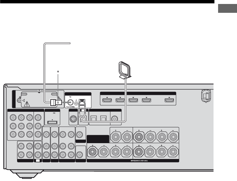
Getting Started
5: Connecting the antennas (aerials)
Connect the supplied AM loop antenna (aerial) and FM wire antenna (aerial).
Before connecting the antennas (aerials), be sure to disconnect the AC power cord (mains lead).
* The shape of the connector varies depending on the area code of this receiver.
Notes
• To prevent noise pickup, keep the AM loop antenna (aerial) away from the receiver and other components.
• Be sure to fully extend the FM wire antenna (aerial).
• After connecting the FM wire antenna (aerial), keep it as horizontal as possible.
LR
VIDEO
OUT
MONITOR
L
R
DIGITAL
(ASSIGNABLE)
DC5V
0.7A MAX
HDMI
ANTENNA
DMPORT
IN 4
ASSIGNABLE (INPUT ONLY)
IN 3
IN 2
IN 3 IN 1 OUT
AM
Y
P
B
/
C
B
COMPONENT VIDEO
OUT IN
P
R
/
C
R
IN 2 IN 1 MONITOR
OUT
SA-CD/CD/CD-R
VIDEO 1
IN
TV
AUDIO
IN
VIDEO
IN
SAT
AUDIO
OUT
AUDIO
OUT
VIDEO
OUT
OPTICAL IN
AUDIO
IN
VIDEO
IN
SUBWOOFER
AUDIO
IN
VIDEO
IN
BD
LR
L
R
SPEAKERS
SAT IN BD IN DVD IN
OPTICAL
CENTER
FRONT A
COAXIAL
ASSIGNABLE (INPUT ONLY)
SURROUND BACK/
FRONT B/
BI-AMP
TV
SIRIUS
LR
SURROUND
(for AUDIO)
EZW-T100
FM wire antenna (aerial) (supplied)
AM loop antenna (aerial) (supplied)
36US
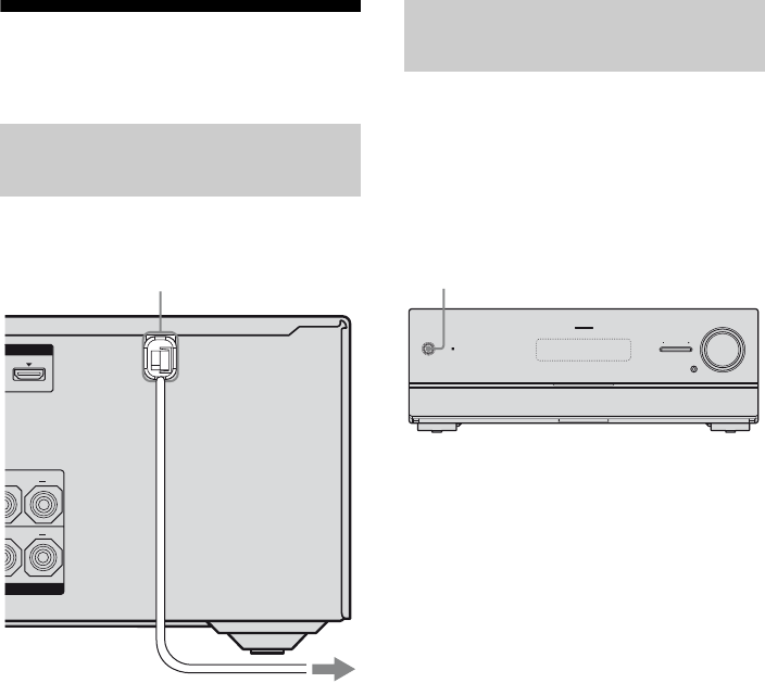
6: Preparing the receiver
and the remote
Connect the AC power cord (mains lead) to a
wall outlet.
Notes
• Before connecting the AC power cord (mains
lead), make sure that metallic wires of the speaker
cords are not touching each other between the
SPEAKERS terminals.
• Connect the AC power cord (mains lead) firmly.
Before using the receiver for the first time,
initialize the receiver by performing the
following procedure. This procedure can also
be used to return settings you have made to
their factory defaults.
Be sure to use the buttons on the receiver for
this operation.
1Press ?/1 to turn off the
receiver.
2Hold down ?/1 for 5 seconds.
After “CLEARING” appears on the
display for a while, “CLEARED!”
appears.
All the settings you have changed or
adjusted are reset to the initial settings.
Connecting the AC power cord
(mains lead)
L
OUT
L
AC power cord (mains lead)
To the wall outlet
Performing initial setup
operations
MULTI CHANNEL DECODING
?/1
INPUT SELECTOR
MUTING
MASTER VOLUME
?/1
37US
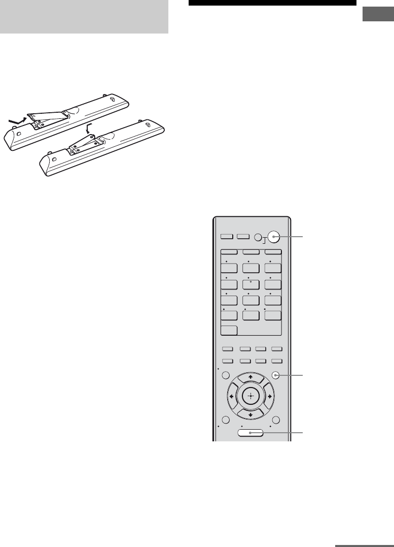
Getting Started
Insert two R6 (size-AA) batteries in the
RM-AAP040 remote commander.
Observe the correct polarity when installing
batteries.
Notes
• Do not leave the remote in an extremely hot or
humid place.
• Do not use a new battery with old ones.
• Do not mix manganese batteries and other kinds of
batteries.
• Do not expose the remote sensor to direct sunlight
or lighting apparatuses. Doing so may cause a
malfunction.
• If you do not intend to use the remote for an
extended period of time, remove the batteries to
avoid possible damage from battery leakage and
corrosion.
• When you replace the batteries, the programmed
remote codes may be cleared. If this happens,
program the remote codes again (page 117).
• When the remote no longer operates the receiver,
replace all the batteries with new ones.
7: Displaying the GUI
menu on the TV screen
You can select the functions or change the
settings of the receiver by using the GUI menu
on the TV screen. Follow the procedure below
to make the settings so that the GUI menu
appears on the TV screen.
Note
GUI menu does not appear on the TV screen when
you have connected your TV to the MONITOR
VIDEO OUT jack.
Tip
See “Operating without connecting to a TV” (page
82) if you want to operate the receiver without
connecting to a TV.
1Connect a TV to this receiver.
See “3: Connecting the TV” (page 21).
2Turn on the TV.
3Press ?/1 to turn on the
receiver.
Inserting batteries into the
remote
1 2 3
4 5 6
7 8 9
-/-- 0/10
ENT/MEM
2CH/
A.DIRECT A.F.D. MOVIE MUSIC
THEATER
SYSTEM STANDBY
RM SET UP
?/1
CLEAR
/
>10
SHIFT
RESOLUTION
VIDEO 1 VIDEO 2 BD
SAT TV
HDMI 3HDMI 2HDMI 1
HDMI 4
SA-CD/
CD DMPORTTUNER
MENU
AV
?/1
RETURN/
EXIT TOOLS/
OPTIONS
HOME
DISPLAY GUI MODE
O
DVD
INPUT
MODE SLEEP
NIGHT
MODE
TV AMP
?/1
GUI MODE
MENU
continued
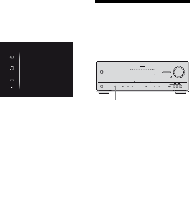
38US
4Press GUI MODE.
After “MENU ON” appears on the
display for a while, “GUI” appears and
the GUI menu appears on the TV screen.
Press MENU if the GUI menu does not
appear on the TV screen.
To exit the menu
Press MENU.
8: Selecting the front
speaker system
You can select the front speakers you want to
drive.
Be sure to use the buttons on the receiver for
this operation.
Press SPEAKERS repeatedly to
select the front speaker system
you want to drive.
* To select “SP B” or “SP A + B”, set “SB Assign”
to “Speaker B” in the Speaker Settings menu (page
73).
To turn off the speaker output
Press SPEAKERS repeatedly until the “SP A”,
“SP B” or “SP A + B” indicators on the display
does not light up. “ALL OFF” appears on the
display for a while.
Note
You cannot switch the front speaker system by
pressing SPEAKERS when the headphones are
connected.
Input
Music
Video
VIDEO 1
VIDEO 2
BD
DVD
SAT
To select Light up
The front speakers connected to the
SPEAKERS FRONT A terminals
SP A
The front speakers connected to the
SPEAKERS SURROUND BACK/
FRONT B/BI-AMP terminals
SP B*
The front speakers connected to both
the SPEAKERS FRONT A and
SURROUND BACK/FRONT B/
BI-AMP terminals (parallel
connection)
SP A + B*
?/1
MASTER VOLUME
SPEAKERS
PHONES 2 CH/
A.DIRECT A.F.D. MOVIE MUSIC INPUT MODE DIMMER DISPLAY
VIDEO 2 IN
VIDEO L AUDIO R
AUTO CAL MIC
MULTI CHANNEL DECODING
INPUT SELECTOR
MUTING
SPEAKERS
39US
Getting Started
To set up front speakers B
1Press GUI MODE.
After “MENU ON” appears on the
display for a while, “GUI” appears and
the GUI menu appears on the TV screen.
Press MENU if the GUI menu does not
appear on the TV screen.
2Press V/v repeatedly to select
“Settings” then press or b.
The Settings menu list appears on the TV
screen.
3Press V/v repeatedly to select
“Speaker”, then press or b.
4Press V/v repeatedly to select
“SP Pattern”, then press or
b.
5Press V/v repeatedly to select
the appropriate speaker pattern
so that there are no surround
back speakers, then press .
6Press V/v repeatedly to select
“SB Assign”, then press or
b.
7Press V/v repeatedly to select
“Speaker B”, then press .
The same signals output from the
SPEAKERS FRONT A terminals can be
output from the SPEAKERS
SURROUND BACK/FRONT B/
BI-AMP terminals.
To exit the menu
Press MENU.
Notes
• Set “SB Assign” to “Speaker B” before you
perform Auto Calibration.
• If you set “SB Assign” to “Speaker B”, the speaker
level and distance settings of the surround back
speakers become invalid, and those of the front
speakers are used.
• If you set “SP Pattern” to a setting with surround
back speakers, you cannot set “SB Assign” to
“Speaker B”.
2CH/
A.DIRECT A.F.D. MOVIE MUSIC
RESOLUTION
.>
<
<
MENU
RETURN/
EXIT TOOLS/
OPTIONS
HOME
DISPLAY GUI MODE
O
INPUT
MODE SLEEP
NIGHT
MODE
– CATEGORY +
V/v/B/b,
GUI MODE
MENU

40US
9: Calibrating the
appropriate speaker
settings automatically
(Auto Calibration)
This receiver is equipped with DCAC (Digital
Cinema Auto Calibration) function which
allows you to perform automatic calibration to
measure the following:
• Speaker connectionsa)
• Polarity of speakers
• Speaker distancea)
• Speaker sizea)
• Speaker level
• Frequency characteristicsa)b)
a)The measurement result is not utilized when the
“Analog Direct” is selected.
b)• Signals with a sampling frequency of higher than
96 kHz are always played back at either 44.1 kHz
or 48 kHz.
• The measurement result is not utilized when
Dolby TrueHD signals with a sampling
frequency of higher than 96 kHz are being
received.
The DCAC is designed to obtain proper sound
balance in your room. However, you can
adjust the speaker levels and balance manually
according to your preference. For details, see
“Test Tone (Test tone)” (page 75).
Before you perform the Auto Calibration, set
up and connect the speakers (page 17–19).
• The AUTO CAL MIC jack is used for the
supplied optimizer microphone only. Do not
connect other microphones to this jack.
Doing so may damage the receiver and the
microphone.
• During the measurement, the sound that
comes out of the speakers is very loud. The
volume of the sound cannot be adjusted. Pay
attention to the presence of children or to the
effect on your neighborhood.
• Perform the measurement in a quiet
environment to avoid the effect of noise and
get a more accurate measurement.
• If there are any obstacles in the path between
the optimizer microphone and the speakers,
the calibration cannot be performed
correctly. Remove any obstacles from the
measurement area to avoid measurement
error.
• When you use a bi-amplifier connection, set
“SB Assign” to “BI-AMP” in the Speaker
Settings menu (page 73) before you perform
Auto Calibration.
• When you use front speakers B connection,
set “SB Assign” to “Speaker B” in the
Speaker Settings menu (page 73) before you
perform Auto Calibration.
• If you want to use surround amplifier, be
sure to pair the surround amplifier to S-AIR
main unit before you perform Auto
Calibration (page 102).
• Select the seating position as position 1, 2 or
3 to save the Auto Calibration result (page
72).
Notes
• The Auto Calibration function does not work in the
following cases.
– Headphones are connected
– SPEAKERS is set to off.
• If you activate the muting function during Auto
Calibration, the muting function will automatically
be set to off.
Before you perform Auto
Calibration
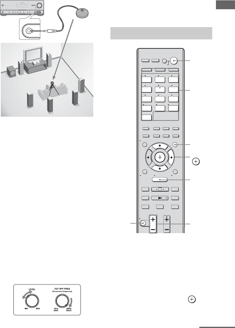
41US
Getting Started
1Connect the supplied optimizer
microphone to the AUTO CAL
MIC jack.
2Set up the optimizer
microphone.
Place the optimizer microphone at your
listening position. Use a stool or tripod so
that the optimizer microphone remains at
the same height as your ears.
On setting up the active
subwoofer
• When a subwoofer is connected, turn on the
subwoofer and turn up the volume
beforehand. Turn the MASTER VOLUME
to just before the mid-point.
• If you connect a subwoofer with a crossover
frequency function, set the value to
maximum.
• If you connect a subwoofer with an auto
standby function, set it to off (deactivated).
Note
Depending on the characteristics of the subwoofer
you are using, the setup distance value may be
further away from the actual position.
1Press GUI MODE.
After “MENU ON” appears on the
display for a while, “GUI” appears and
the GUI menu appears on the TV screen.
Press MENU if the GUI menu does not
appear on the TV screen.
2Press V/v repeatedly to select
“Settings”, then press or b.
The Settings menu list appears on the TV
screen.
?/1
MASTER VOLUME
SPEAKERS
PHONES 2 CH/
A.DIRECT A.F.D. MOVIE MUSIC INPUT MODE DIMMER DISPLAY
VIDEO 2 IN
VIDEO L AUDIO R
AUTO CAL MIC
MULTI CHANNEL DECODING
INPUT SELECTOR
MUTING
AUTO CAL MIC
Optimizer microphone
Performing Auto Calibration
1 2 3
4 5 6
7 8 9
-/-- 0/10
ENT/MEM
2CH/
A.DIRECT A.F.D. MOVIE MUSIC
THEATER
SYSTEM STANDBY
RM SET UP
?/1
CLEAR
/
>10
SHIFT
TUNING – TUNING +
DISC SKIP D.TUNING
RESOLUTION
.
mM
>
Xx
MUTING
VIDEO 1 VIDEO 2 BD
SAT TV
HDMI 3HDMI 2HDMI 1
HDMI 4
SA-CD/
CD DMPORTTUNER
TV VOL
MASTER VOL
TV CH
PRESET
<
<
MENU
AV
?/1
RETURN/
EXIT TOOLS/
OPTIONS
HOME
DISPLAY GUI MODE
O
DVD
INPUT
MODE SLEEP
NIGHT
MODE
TV AMP
– CATEGORY +
CATEGORY MODE
V/v/b,
GUI
MODE
MENU
MASTER
VOL +/–
Input
buttons
?/1 switch
MUTING
continued
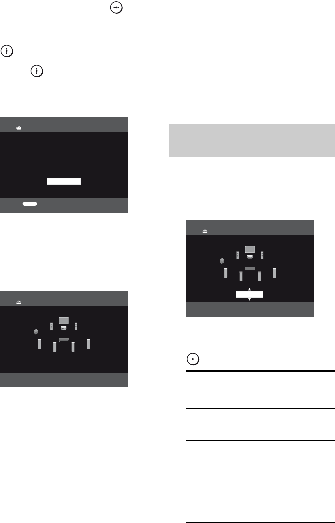
42US
3Press V/v repeatedly to select
“Auto Cal.”, then press or b.
4 Press V/v repeatedly to select
“Auto Cal. Start”, then press
or b.
5Press to select “START”.
6The measurement starts in five
seconds.
7Measurement starts.
The measurement process will take
approximately 30 seconds with a test
tone. Wait until the measurement process
completes.
Tip
The measurements may not be performed correctly
or Auto Calibration cannot be performed when
special speakers, such as dipole speakers are used.
To cancel the measurement
The measurement will be canceled when you
do the following:
– Press ?/1.
– Press the input buttons on the remote or
press the INPUT SELECTOR +/–
repeatedly on the receiver.
– Press MUTING.
– Press SPEAKERS on the receiver.
– Change the volume level.
– Connect the headphones.
1Confirm the measurement
result.
When the measurement ends, a beep
sounds.
2Press V/v repeatedly to select
the item you want, then press
.
Count Down
Please press enter key
to stop.
5
Auto Calibration
RETURN
CANCEL
Auto Calibration
TONE T. S. P.
WOOFER
Confirming/saving the
measurement results
Item Explanation
Retry Performs the Auto Calibration
again.
Save Saves the measurement
results and exits the setting
process.
Warning Displays warning concerning
the measurement results. See
“Message list after Auto
Calibration measurement”
(page 44).
Phase* Displays the phase of each
speaker (in phase/out of
phase).
Auto Calibration
Save
43US
Getting Started
* When the speaker(s) is (are) out of the phase,
“OUT” is displayed on the TV screen. The
“+” and “–” terminals of the speaker may be
connected the other way around.
However, depending on the speakers, “OUT”
appears on the TV screen even though the
speakers are connected properly. This is
because of the speakers’ specifications. In
this case, you can continue to use the
receiver.
3Select “Save” in step 2 to save
the measurement result.
4Press V/v repeatedly to select
the Auto Calibration Type, then
press .
Tip
The size of a speaker (“Large”/“Small”) is
determined by the low frequency characteristics.
The measurement results may vary, depending on
the position of the optimizer microphone and
speakers, and the shape of the room. It is
recommended that you follow the measurement
results. However, you can change those settings in
the Speaker Settings menu. Save the measurement
results first, then try to change the settings if you
want.
Distance Displays the measurement
result for speaker distance.
Level Displays the measurement
result for speaker level.
Exit Exits the setting process
without saving the
measurement results.
Parameter Explanation
Full Flat Makes the measurement of
frequency from each speaker
flat.
Engineer Sets the frequency to one that
matches that of the Sony
listening room standard.
Front
Reference
Adjusts the characteristics of
all the speakers to match the
characteristics of the front
speaker.
Off Sets the Auto Calibration to
off.
Item Explanation
Auto Cal. Type
Engineer
Front Reference
Off
Auto Calibration
RETURN
Full Flat
44US
Error Code 31, 32, 33
1When you press , “RETRY?” appears.
2Press B/b to select “YES”.
3Press .
The measurement starts in five seconds.
When “Warning” appears
If a warning on the measurement result is
present, detailed information is displayed.
Press to return to step 1 of “Confirming/
saving the measurement results” (page 42).
Tip
Depending on the position of the subwoofer, the
measurement results for polarity may vary.
However, there will be no problems even if you
continue to use the receiver with that value.
Message list after Auto Calibration measurement
Error and
warning code
Explanation
Error Code 31 The SPEAKERS is set to off. Set it to others and perform the Auto Calibration again.
Error Code 32 None of the speakers were detected. Make sure that the optimizer microphone is connected
properly and perform the measurement again.
If the optimizer microphone is connected properly but the error code appears, the optimizer
microphone cable may be damaged or improperly connected.
Error Code 33 • None of the front speakers are connected or only one front speaker is connected.
• The optimizer microphone is not connected.
• Either the left or right surround speakers is not connected.
• Surround back speakers are connected even though surround speakers are not connected.
Connect the surround speaker(s) to the SPEAKERS SURROUND terminals.
• The surround back speaker is connected only to the SPEAKERS SURROUND BACK/
FRONT B/BI-AMP R terminals. When you connect only one surround back speaker,
connect it to the SPEAKERS SURROUND BACK/FRONT B/BI-AMP L terminals.
Warning 40 The measurement has completed. However, the noise level is high. You may be able to
perform the measurement properly if you try it again, even though the measurement cannot
be performed in all environments. Try to perform the measurement in a quiet environment.
Warning 41
Warning 42
The input from the microphone is too big.
• It may be the distance between the speaker and the microphone are too close.
Retry the measurement after setting apart from each other.
Warning 43 The distance and position of a subwoofer cannot be detected. This may be caused by noise.
Try to perform the measurement in a quiet environment.
NO WARNING There is no warning information.
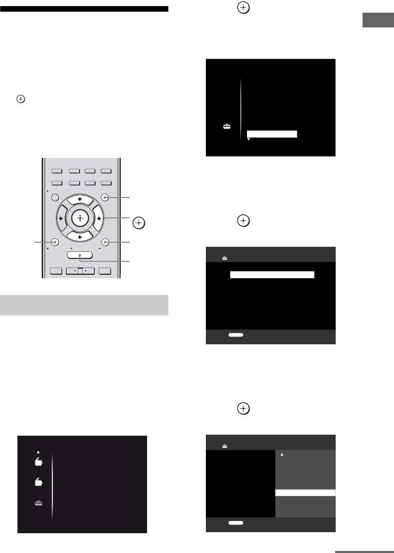
45US
Getting Started
Guide to on-screen
display operation
You can display the menu of the receiver on
the TV screen and select the function you want
to use on the TV screen by pressing V/v/B/b
and on the remote.
To display the menu of the receiver on the TV
screen, make sure that the receiver is in “GUI
MODE” following the steps in “7: Displaying
the GUI menu on the TV screen” (page 37).
1Press GUI MODE.
After “MENU ON” appears on the
display for a while, “GUI” appears and
the GUI menu appears on the TV screen.
Press MENU if the GUI menu does not
appear on the TV screen.
2Press V/v repeatedly to select a
menu you want.
3Press or b to enter the
menu.
The menu item list appears on the TV
screen.
4Press V/v repeatedly to select
the menu item you want to
adjust.
5Press or b to enter the
menu item.
6Press V/v repeatedly to select
the parameter you want to
adjust.
7Press or b to enter the
parameter.
Using the menu
2CH/
A.DIRECT A.F.D. MOVIE MUSIC
RESOLUTION
.>
<
<
MENU
RETURN/
EXIT TOOLS/
OPTIONS
HOME
DISPLAY GUI MODE
O
INPUT
MODE SLEEP
NIGHT
MODE
– CATEGORY +
V/v/b,
GUI MODE
MENU
TOOLS/
OPTIONS
RETURN/
EXIT O
AM
AM
SR
SR
Setting
Auto Cal.
Speaker
Surround
EQ
Audio
Setting
Auto Cal.
Speaker
Surround
EQ
Audio
Main/Sub
Dec. Priority:
Dual Mono:
Audio Settings
RETURN
0 ms
A/V Sync:
30 ms
A/V Sync:
20 ms
10 ms
Dec. Priority:
Dual Mono:
Audio Settings
RETURN
0 ms
continued
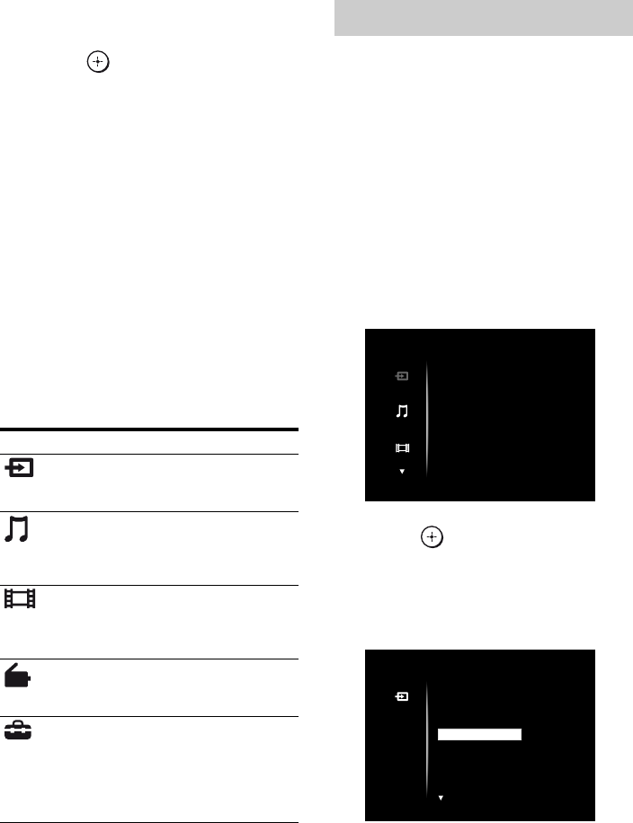
46US
8Press V/v repeatedly to select
the setting you want.
9Press to enter the setting.
10Repeat steps 2 to 9 to make
other settings.
To return to the previous screen
Press RETURN/EXIT O.
To exit the menu
Press MENU.
To exit “GUI MODE”
Press GUI MODE. “MENU OFF” appears and
you can operate the receiver using the menu in
the display of the receiver.
Overview of the main menus
When you press TOOLS/OPTIONS, the
option menu for the selected main menu are
displayed. You can select a related function
without reselecting the menu.
1Press GUI MODE.
After “MENU ON” appears on the
display for a while, “GUI” appears and
the GUI menu appears on the TV screen.
Press MENU if the GUI menu does not
appear on the TV screen.
2Press V/v repeatedly to select a
menu you want.
3Press or b to enter the
menu.
The menu item list appears on the TV
screen.
Example: when you select “Input”.
Menu icon Description
Input Selects the input source
component connected to the
receiver (page 47).
Music Selects the music from the
audio component connected
to the DIGITAL MEDIA
PORT adapter (page 49).
Video Selects the images from the
video components connected
to the DIGITAL MEDIA
PORT adapter (page 49).
FM/AM/SR Selects the built-in FM/AM
radio or satellite tuner
connected (page 52, 55).
Settings You can adjust the settings of
the speakers, the surround
effect, equalizer, audio,
video and other inputs
connected to the HDMI jacks
(page 70).
Using the option menu
Input
Music
Video
VIDEO 1
VIDEO 2
BD
DVD
SAT
Input
VIDEO 1
VIDEO 2
DVD
SAT
BD
47US
Playback
4Press TOOLS/OPTIONS while
the menu item list is displayed.
The option menu appears.
5Press V/v repeatedly to select
the option menu item you want,
then press or b.
6Press V/v repeatedly to select
the parameter you want, then
press .
To exit the menu
Press MENU.
Enjoying sound/images
from the component
connected to the receiver
1Press GUI MODE.
After “MENU ON” appears on the
display for a while, “GUI” appears and
the GUI menu appears on the TV screen.
Press MENU if the GUI menu does not
appear on the TV screen.
Input
VIDEO 1
VIDEO 2
DVD
SAT
BD Name lnput
Input Assign
Playback
1 2 3
4 5 6
7 8 9
-/-- 0/10
ENT/MEM
2CH/
A.DIRECT A.F.D. MOVIE MUSIC
THEATER
SYSTEM STANDBY
RM SET UP
?/1
CLEAR
/
>10
SHIFT
TUNING – TUNING +
DISC SKIP D.TUNING
RESOLUTION
.
mM
>
Xx
MUTING
VIDEO 1 VIDEO 2 BD
SAT TV
HDMI 3HDMI 2HDMI 1
HDMI 4
SA-CD/
CD DMPORTTUNER
TV VOL
MASTER VOL
TV CH
PRESET
<
<
MENU
AV
?/1
F1 F2
TV INPUT
TOP MENU MENU
BD/DVD
WIDE
RETURN/
EXIT TOOLS/
OPTIONS
HOME
DISPLAY GUI MODE
O
DVD
INPUT
MODE SLEEP
NIGHT
MODE
TV AMP
– CATEGORY +
CATEGORY MODE
V/v/B/b,
GUI MODE
MENU
TOOLS/
OPTIONS
MUTING MASTER
VOL +/–
Input
buttons
?/1 switch
RETURN/
EXIT O
continued
48US
2Press V/v repeatedly to select
“Input”, then press or b.
The menu item list appears on the TV
screen.
3Press V/v repeatedly to select
the component you want, then
press .
4Turn on the component and
start playback.
5Press MASTER VOL +/– to
adjust the volume.
You can also use MASTER VOLUME on
the receiver.
Tips
• You can press INPUT SELECTOR +/– on the
receiver repeatedly or press input buttons on the
remote to select the component you want.
• You can adjust the volume differently depending
on the speed with which you turn the MASTER
VOLUME on the receiver.
To turn the volume up or down quickly: turn the
knob quickly.
To make fine adjustment: turn the knob slowly.
• You can adjust the volume differently depending
on the length of time you press and hold the
MASTER VOL +/– button on the remote.
To turn the volume up or down quickly: press and
hold the button.
To make a fine adjustment: press the button and
release it immediately.
To activate the muting function
Press MUTING.
The muting function will be canceled when
you do the following.
• Press MUTING again.
• Increase the volume.
• Turn off the receiver.
To avoid damaging your
speakers
Before you turn off the receiver, be sure to turn
down the volume level.
Selected input Components that can
be played back
VIDEO 1 VCR, etc., connected to the
VIDEO 1 jack
VIDEO 2 Camcorder, video game,
etc., connected to the
VIDEO 2 IN jack
BD Blu-ray disc player, etc.,
connected to the BD jack
DVD DVD player, etc.,
connected to DVD jack
SAT Satellite tuner, set-top box,
etc., connected to SAT jack
TV TV, etc., connected to TV
jack
SA-CD/CD/
CD-R
Super Audio CD player,
CD player, etc., connected
to the SA-CD/CD/CD-R
jack
HDMI 1, 2, 3, 4 HDMI components
connected to the HDMI IN
1, HDMI IN 2, HDMI IN 3
(for AUDIO) or HDMI IN
4 jack
49US
Playback
You can enter a name of up to 8 characters for
inputs and display it.
This is convenient for labeling the jacks with
the names of the connected components.
1Press V/v repeatedly on the
“Input” screen to select the
input you want.
2Press TOOLS/OPTIONS.
3Press V/v repeatedly to select
“Name Input”, then press .
4Press V/v/B/b to select a
character, then press .
The name you entered is registered.
To cancel naming input
Press RETURN/EXIT O.
Enjoying sound/images
from the components
connected to the DIGITAL
MEDIA PORT
The DIGITAL MEDIA PORT (DMPORT)
allows you to enjoy picture and sound from a
network system such as a portable audio/video
source or computer.
For details on connecting the DIGITAL
MEDIA PORT adapter, see “Connecting
audio components” (page 23).
Sony offers the following DIGITAL MEDIA
PORT adapters as of May 2009:
• TDM-BT1/BT10 Bluetooth™ Wireless
Audio Adapter
• TDM-NW10 DIGITAL MEDIA PORT
Adapter
• TDM-NC1 Wireless Network Audio Client
• TDM-iP10/iP50 DIGITAL MEDIA PORT
Adapter
• TDM-MP10 DIGITAL MEDIA PORT
Adapter
The DIGITAL MEDIA PORT adapter is an
optional product.
Notes
• Do not connect an adapter other than the DIGITAL
MEDIA PORT adapter to the DMPORT jack.
• Before disconnecting the DIGITAL MEDIA
PORT adapter, be sure to turn off the receiver.
• Do not connect or disconnect the DIGITAL
MEDIA PORT adapter while the receiver is turned
on.
• Depending on the type of DIGITAL MEDIA
PORT adapter, video output may not be possible.
• The DIGITAL MEDIA PORT adapters are
available for purchase depending on the area.
Naming the input (Name Input)
Input
VIDEO 1
VIDEO 2
DVD
SAT
BD
Input Assign
Name lnput
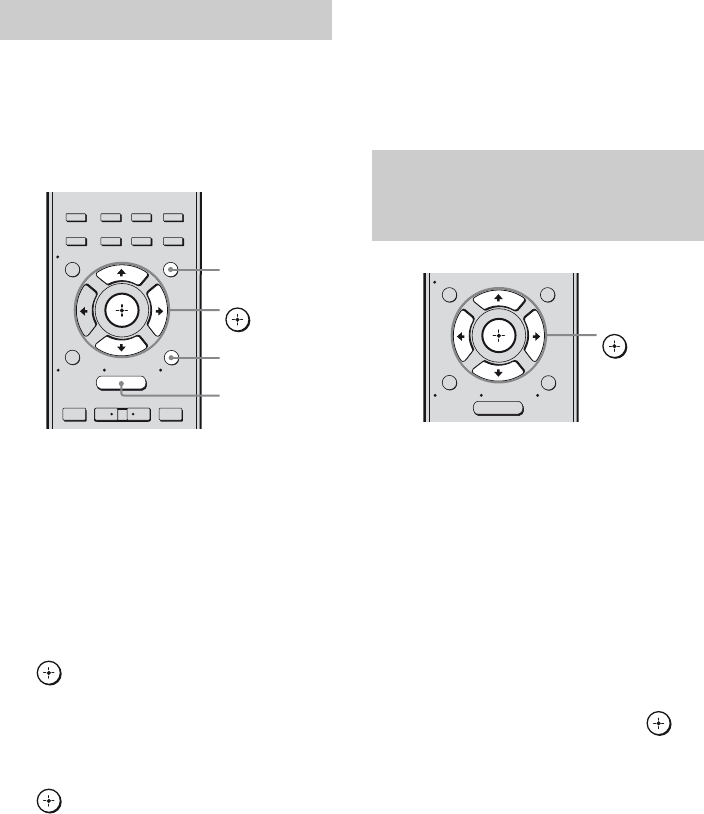
50US
You can select an operation screen using the
GUI menu, depending on the DIGITAL
MEDIA PORT adapter you want to use. For
some adapter, such as TDM-BT1, the
operation screen is fixed and you cannot
change it on the GUI screen.
1Press GUI MODE.
After “MENU ON” appears on the
display for a while, “GUI” appears and
the GUI menu appears on the TV screen.
Press MENU if the GUI menu does not
appear on the TV screen.
2Press V/v repeatedly to select
“Music” or “Video”, then press
or b.
3Press TOOLS/OPTIONS.
4Press V/v repeatedly to select
the mode you want, then press
.
The details of each mode are as follows:
•System GUI
This mode is for the TDM-iP50 and
TDM-NC1. The list of tracks will be
displayed on the GUI screen of the
receiver. You can select a track you
want and play it back on each GUI
screen.
•iPod
This mode is for the TDM-iP50.
If the option menu does not appear on the
screen, refer to the operating instructions
of the connected component.
When an adapter other than iPod is
connected, a hierarchical menu does not
appear.
To operate the TDM-iP50 or
TDM-NC1 using the GUI menu of
the receiver
1Make sure that “System GUI” is
selected in step 4 in “Selecting
the operation screen” (page
50).
2Press V/v/B/b repeatedly to
select the content you want
from the contents list displayed
on the GUI screen, press to
play it back.
Selecting the operation screen
2CH/
A.DIRECT A.F.D. MOVIE MUSIC
RESOLUTION
.>
<
<
MENU
RETURN/
EXIT TOOLS/
OPTIONS
HOME
DISPLAY GUI MODE
O
INPUT
MODE SLEEP
NIGHT
MODE
– CATEGORY +
V/v/b,
GUI MODE
MENU
TOOLS/
OPTIONS
Operating the component
connected to the DIGITAL MEDIA
PORT adapter
MENU
RETURN/
EXIT TOOLS/
OPTIONS
HOME
DISPLAY GUI MODE
O
V/v/B/b,
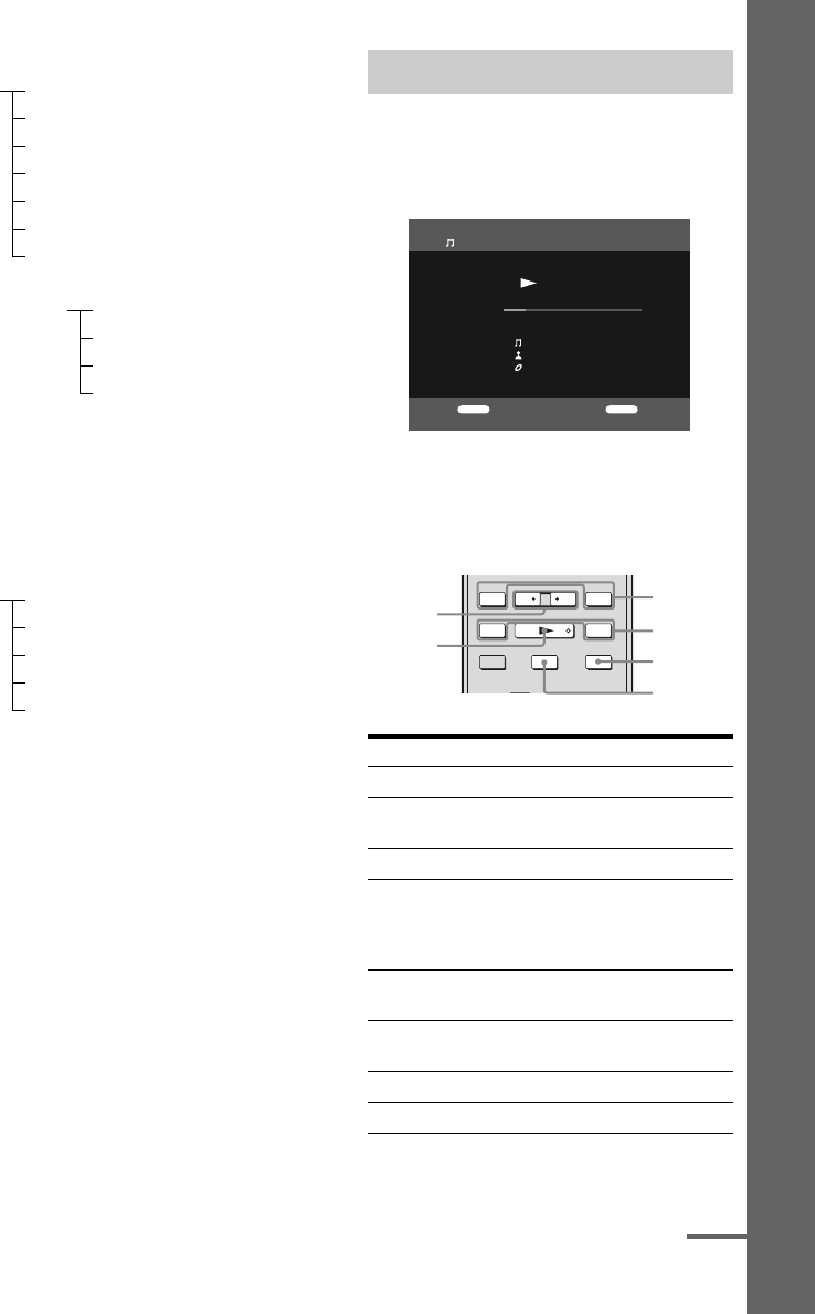
51US
Playback
Contents list for audio
a)Displayed only when M-crew Server is connected.
b)Displayed only when a DLNA server other than
M-crew Server is connected.
c)Displayed as “Genre”, “Artist” or “Album”,
depending on setting of “List Mode”.
Contents list for video
To operate the TDM-iP50 using
the iPod menu
Make sure that “iPod” is selected in step 4 in
“Selecting the operation screen” (page 50).
For details on operating the iPod, refer to the
operating instructions supplied with the iPod.
During playback of the selected track, the
displayed screen changes depending on the
DIGITAL MEDIA PORT adapter connected.
You can operate the components connected to
the DIGITAL MEDIA PORT adapter using
the following buttons on the remote of the
receiver.
* Fast-backward/forward while pressing and
holding the m/M button.
iPod Playlists > Playlist > Track
Artists > Artist > Album > Track
Albums > Album > Track
Songs > Track
Genres > Genre > Artist > Album > Track
Composers > Composer > Track
Audiobooks > Audiobook
Network Client Music Surfin
a)
> Album
c)
> Track
Playlist
a)
> Playlist > Track
Web Radio
a)
> Station > Program
Music Library
b)
> Album > Track
iPod Movies > Content
TV Shows > Episode > Content
Music Videos > Artist > Content
Video Playlists > Video Playlist > Content
Video Podcasts > Episode > Content
Playing the selected track
To Do the following
Play Press N.
Pause Press X. To resume play,
press the button again.
Stop Press x.
Find the beginning of a
track during playback, or
find the beginning of the
previous track
Press ..
Find the beginning of the
next track
Press >.
Skip to the previous
album
Press B•.
Skip to the next album Press •b.
Go backward/forward Press m/M.*
Music Player
RETURN OPTIONS
Title Sample
0:17
1/1
Artist Sample
Album Sample
Example of a “System GUI” screen
TUNING – TUNING +
DISC SKIP D.TUNING
.
mM
>
Xx
TV VOL
MASTER VOL
TV CH
PRESET
<
<
– CATEGORY +
CATEGORY MODE
./>
m/M
x
X
B•/•b
N
continued
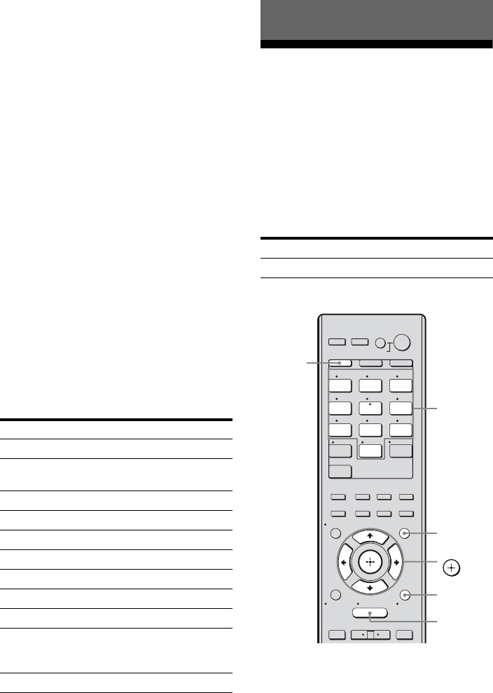
52US
Option parameters in the play
modes
xRepeat Mode (TDM-iP50 only)
•OFF
•One
•All
xShuffle (TDM-iP50 only)
•OFF
• Songs
•Albums
xList Mode (TDM-NC1 only)
•All Tracks
•Disc List
• Artist List
•Genre List
xAudiobook Speed (TDM-iP50
only)
•Low
•Normal
•High
DIGITAL MEDIA PORT message
list
* TDM-NC1 only.
Listening to FM/AM radio
You can listen to FM and AM broadcasts
through the built-in tuner. Before operation,
make sure you have connected the FM and
AM antennas (aerials) to the receiver (page
35).
Tip
The tuning scale for direct tuning differs depending
on the area code as shown in the following table. For
details on area codes, see page 4.
* The AM tuning scale can be changed (page 54).
Message appears Explanation
No Adapter The adapter is not connected.
No Device There is no device connected
to the adapter.
No Audio No audio file was found.
Loading The data is being read.
No Server* There is no server connected.
No Track* No track was found.
No Item No item was found.
Connecting* Connecting to the server.
Configuring* The network is setting up.
Warning* Check the display of the
DIGITAL MEDIA PORT
adapter.
Searching* Searching the server.
Tuner Operations
Area code FM AM
U, CA 100 kHz 10 kHz*
1 2 3
4 5 6
7 8 9
-/-- 0/10
ENT/MEM
2CH/
A.DIRECT A.F.D. MOVIE MUSIC
THEATER
SYSTEM STANDBY
RM SET UP
?/1
CLEAR
/
>10
SHIFT
RESOLUTION
.>
VIDEO 1 VIDEO 2 BD
SAT TV
HDMI 3HDMI 2HDMI 1
HDMI 4
SA-CD/
CD DMPORTTUNER
<
<
MENU
AV
?/1
RETURN/
EXIT TOOLS/
OPTIONS
HOME
DISPLAY GUI MODE
O
DVD
INPUT
MODE SLEEP
NIGHT
MODE
TV AMP
– CATEGORY +
V/v/B/b,
GUI MODE
MENU
TOOLS/
OPTIONS
SHIFT
Numeric
buttons

53US
Tuner Operations
1Press GUI MODE.
After “MENU ON” appears on the
display for a while, “GUI” appears and
the GUI menu appears on the TV screen.
Press MENU if the GUI menu does not
appear on the TV screen.
2Press V/v repeatedly to select
“FM” or “AM”, then press or
b.
The FM or AM menu list appears on the
TV screen.
3Press V/v repeatedly to select
“Auto Tuning”, then press
or b.
4Press V/v.
Press V to scan from low to high, press v
to scan from high to low.
The receiver stops scanning whenever a
station is received.
In case of poor FM stereo
reception
1Tune in the station you want to listen to
using Auto Tuning, Direct Tuning (page
53), or select the preset station you want
(page 54).
2Press TOOLS/OPTIONS.
3Press V/v repeatedly to select “FM Mode”,
then press or b.
4Press V/v repeatedly to select “MONO”,
then press .
You can enter the frequency of a station
directly by using the numeric buttons.
1Press GUI MODE.
After “MENU ON” appears on the
display for a while, “GUI” appears and
the GUI menu appears on the TV screen.
Press MENU if the GUI menu does not
appear on the TV screen.
2Press V/v repeatedly to select
“FM” or “AM”, then press or
b.
3Press V/v repeatedly to select
“Direct Tuning”, then press
or b.
4Press SHIFT, then press
numeric buttons to enter the
frequency.
Example 1: FM 102.50 MHz
Select 1 b 0 b 2 b 5
Example 2: AM 1,350 kHz
Select 1 b 3 b 5
Tip
If you have tuned in an AM station, adjust
the direction of the AM loop antenna
(aerial) for optimum reception.
5Press .
If you cannot tune in a station
“– – – .– – MHz” appears and then the screen
returns to the current frequency.
Make sure you have entered the right
frequency. If not, repeat step 4. If you still
cannot tune in a station, the frequency is not
used in your area.
Tuning into a station
automatically (Auto Tuning)
Tuning into a station directly
(Direct Tuning)
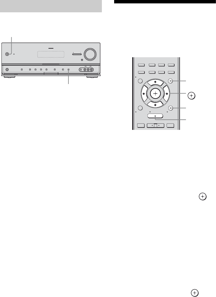
54US
You can change the AM tuning scale to either
9 kHz or 10 kHz on the receiver.
1Press ?/1 to turn off the
receiver.
2While holding down DISPLAY,
press ?/1 on the receiver.
3Change the current AM tuning
scale to 9 kHz (or 10 kHz).
To reset the scale to 10 kHz (or 9 kHz),
repeat the procedure above.
Note
All preset stations will be erased when you change
the tuning scale.
Presetting FM/AM radio
stations
You can preset up to 30 FM and 30 AM
stations. Then you can easily tune in the
stations you often listen to.
1Press GUI MODE.
After “MENU ON” appears on the
display for a while, “GUI” appears and
the GUI menu appears on the TV screen.
Press MENU if the GUI menu does not
appear on the TV screen.
2Press V/v repeatedly to select
“FM” or “AM”, then press or
b.
3Tune in the station that you
want to preset using Automatic
Tuning (page 53) or Direct
Tuning (page 53).
In case of poor FM stereo reception,
switch the FM reception mode (page 53).
4Press TOOLS/OPTIONS.
The option menu appears.
5Press V/v repeatedly to select
“Memory”, then press or b.
6Press V/v repeatedly to select a
preset number.
Changing the AM tuning scale
?/1
MASTER VOLUME
SPEAKERS
PHONES 2 CH/
A.DIRECT A.F.D. MOVIE MUSIC INPUT MODE DIMMER DISPLAY
VIDEO 2 IN
VIDEO L AUDIO R
AUTO CAL MIC
MULTI CHANNEL DECODING
INPUT SELECTOR
MUTING
?/1
DISPLAY
2CH/
A.DIRECT A.F.D. MOVIE MUSIC
RESOLUTION
.>
<
<
MENU
RETURN/
EXIT TOOLS/
OPTIONS
HOME
DISPLAY GUI MODE
O
INPUT
MODE SLEEP
NIGHT
MODE
– CATEGORY +
V/v/B/b,
GUI MODE
MENU
TOOLS/
OPTIONS

55US
Tuner Operations
7Press .
The station is stored as the selected preset
number.
8Repeat steps 3 to 7 to preset
another station.
You can store station as follows:
• AM band: AM 1 to AM 30
• FM band: FM 1 to FM 30
1Repeat steps 1 and 2 of
“Presetting FM/AM radio
stations”.
2Press V/v repeatedly to select
the preset station you want.
Preset numbers from 1 to 30 are available.
1On “FM” or “AM” screen, press
V/v repeatedly to select the
preset number on which you
have stored the station and
which you want to name.
2Press TOOLS/OPTIONS.
The option menu appears.
3Press V/v repeatedly to select
“Name Input”, then press .
4Press V/v/B/b to select a
character, then press .
The name you entered is registered.
Listening to Satellite
Radio
To listen to Satellite Radio, you’ll need to
connect a SIRIUS Satellite Radio tuner (sold
separately) to your Sirius-Ready receiver.
SIRIUS Satellite Radio is available to
residents of the US (except Alaska and
Hawaii) and Canada.
Satellite Radio delivers a variety of
commercial-free music from categories
ranging from Pop, Rock, Country, R&B,
Dance, Jazz, Classical and many more plus
coverage of all the top professional and
college sports including play by play games
from select leagues and teams. Additional
programming includes expert sports talk,
uncensored entertainment, comedy, family
programming, local traffic and weather and
news from your most trusted sources.
Once you’ve purchased a SIRIUS tuner you’ll
need to activate it and subscribe to begin
enjoying the service. Easy to follow
installation and setup instructions are provided
with the SIRIUS tuner. There are a variety of
programming packages available, including
the option of adding “The Best of XM”
programming to the SIRIUS service. The
“Best of XM” service is not available to
SIRIUS Canada subscribers at this time.
Please check with SIRIUS Canada for any
updates using the numbers and web address
below.
Family friendly packages are also available to
restrict channels featuring content that may be
inappropriate for children.
To subscribe to SIRIUS, U.S. and Canadian
customers can call 1-888-539-SIRI (1-888-
539-7474) or visit sirius.com (US) or
siriuscanada.ca (Canada).
Tuning to preset stations
Naming preset stations (Name
Input)
continued
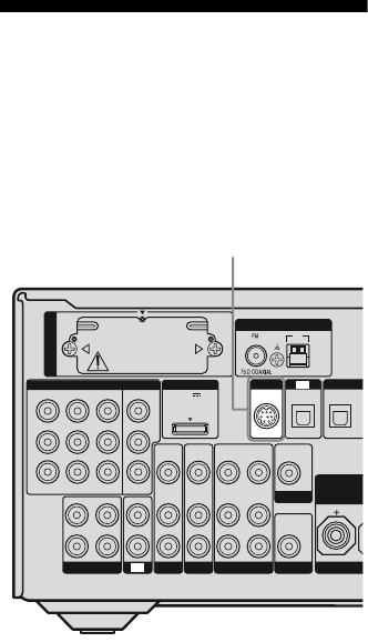
56US
SIRIUS and all related marks and logos are
trademarks of Sirius XM Radio Inc. and its
subsidiaries. All other marks and logos are the
property of their respective owners. All rights
reserved. SIRIUS subscription sold separately.
Taxes and a one-time activation fee may apply.
SIRIUS tuner required (sold separately) to receive
the SIRIUS service. All programming and fees
subject to change. It is prohibited to copy,
decompile, disassemble, reverse engineer, hack,
manipulate or otherwise make available any
technology or software incorporated in receivers
compatible with the SIRIUS Satellite Radio System.
Service not available in Alaska or Hawaii.
Connecting the SIRIUS
Satellite Radio
Connect the SiriusConnect Home tuner. When
you use the SiriusConnect Home tuner with
this receiver, be sure to connect the AC power
adaptor supplied with the tuner to a wall outlet.
Note
Keep the SiriusConnect Home tuner, antenna, and
AC power adaptor away from the speaker cords and
the power cord to avoid picking up noise.
VIDEO
OUT
MONITOR
L
R
DIG
I
DC5V
0.7A MAX
ANTENNA
DMPORT
IN 3
AM
Y
P
B
/
C
B
COMPONENT VIDEO
OUT IN
P
R
/
C
R
IN 2 IN 1 MONITOR
OUT
SA-CD/CD/CD-R
VIDEO 1
IN
TV
AUDIO
IN
VIDEO
IN
SAT
AUDIO
OUT
AUDIO
OUT
VIDEO
OUT
OPTICAL IN
AUDIO
IN
VIDEO
IN
SUBWOOFER
AUDIO
IN
VIDEO
IN
BD
R
L
R
SAT IN
OPTI
ASSIGNABLE (INPUT ONLY)
SURROUN
D
FRON
T
BI-A
M
TV
SIRIUS
EZW-T100
SIRIUS jack
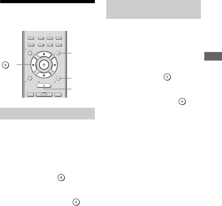
57US
Tuner Operations
Preparing to listen to the
SIRIUS Satellite Radio
1Press GUI MODE.
After “MENU ON” appears on the
display for a while, “GUI” appears and
the GUI menu appears on the TV screen.
Press MENU if the GUI menu does not
appear on the TV screen.
2Press V/v repeatedly to select
“SR”, then press or b.
3Press TOOLS/OPTIONS, then
press V/v repeatedly to select
“Sirius ID”, then press or b.
4Check the SIRIUS ID on the TV
screen and write it in the space
provided here.
ID:_____________________________
You can also check the SIRIUS ID using
the display on the receiver.
1Press GUI MODE.
After “MENU ON” appears on the
display for a while, “GUI” appears and
the GUI menu appears on the TV screen.
Press MENU if the GUI menu does not
appear on the TV screen.
2Press V/v repeatedly to select
“SR”, then press or b.
3Press TOOLS/OPTIONS, then
press V/v repeatedly to select
“Antenna”, then press or b.
4While checking the quality of
the reception, adjust the
direction of the antenna to
obtain the best reception.
To exit the menu
Press MENU.
Checking the SIRIUS Radio ID
2CH/
A.DIRECT A.F.D. MOVIE MUSIC
RESOLUTION
.>
<
<
MENU
RETURN/
EXIT TOOLS/
OPTIONS
HOME
DISPLAY GUI MODE
O
INPUT
MODE SLEEP
NIGHT
MODE
– CATEGORY +
V/v/B/b,
GUI MODE
MENU
TOOLS/
OPTIONS
Checking receiving conditions
(Antenna Aiming)
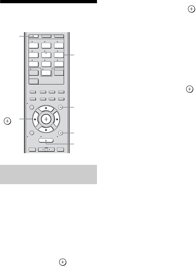
58US
Selecting a channel of the
SIRIUS Satellite Radio
You can select a channel from one category or
all the categories.
1Press GUI MODE.
After “MENU ON” appears on the
display for a while, “GUI” appears and
the GUI menu appears on the TV screen.
Press MENU if the GUI menu does not
appear on the TV screen.
2Press V/v repeatedly to select
“SR”, then press or b.
3Press V/v repeatedly to select
the category, then press or
b.
• All: You can select a channel from all
the categories.
• (category name): You can select a
channel from one category.
Note
When the “Preset Mode” screen is displayed,
press TOOLS/OPTIONS, then press V/v
repeatedly to select “Category Mode”.
4Press V/v repeatedly to select
the channel, then press .
The selected channel is being received.
The channel information is displayed on
the TV screen.
Note
When you select a channel in the “Category Mode,”
the channel you selected may not be the one in the
category you want. This is because one channel may
belong to more than one category.
Selecting a channel by category
(Category Mode)
1 2 3
4 5 6
7 8 9
-/-- 0/10
ENT/MEM
2CH/
A.DIRECT A.F.D. MOVIE MUSIC
CLEAR
/
>10
SHIFT
RESOLUTION
.>
VIDEO 1 VIDEO 2 BD
SAT TV
HDMI 3HDMI 2HDMI 1
HDMI 4
SA-CD/
CD DMPORTTUNER
<
<
MENU
RETURN/
EXIT TOOLS/
OPTIONS
HOME
DISPLAY GUI MODE
O
DVD
INPUT
MODE SLEEP
NIGHT
MODE
TV AMP
– CATEGORY +
V/v/B/b,
GUI MODE
MENU
TOOLS/
OPTIONS
SHIFT
Numeric
buttons
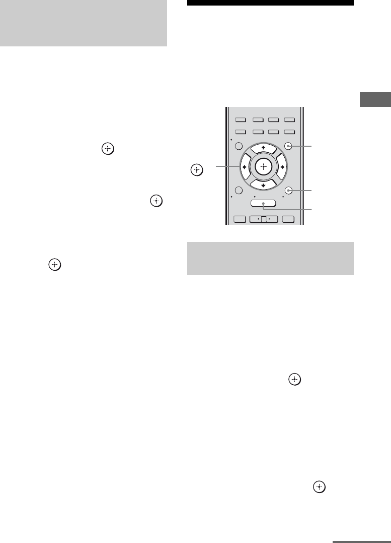
59US
Tuner Operations
1Press GUI MODE.
After “MENU ON” appears on the
display for a while, “GUI” appears and
the GUI menu appears on the TV screen.
Press MENU if the GUI menu does not
appear on the TV screen.
2Press V/v repeatedly to select
“SR”, then press or b.
3Press TOOLS/OPTIONS.
4Press V/v repeatedly to select
“Direct Tuning”, then press .
5Press SHIFT, then press
numeric buttons to enter the
channel number.
6Press .
The selected channel is tune in.
Presetting SIRIUS
Satellite Radio channels
You can select the channels you want directly
by presetting them using the preset numbers.
You can preset up to 30 SIRIUS Satellite
Radio channels.
1Press GUI MODE.
After “MENU ON” appears on the
display for a while, “GUI” appears and
the GUI menu appears on the TV screen.
Press MENU if the GUI menu does not
appear on the TV screen.
2Press V/v repeatedly to select
“SR”, then press or b.
3Select a channel you want to
preset using Category Tuning
(page 58) or Direct Tuning
(page 59).
4Press TOOLS/OPTIONS.
5Press V/v repeatedly to select
“Memory”, then press or b.
Selecting a channel by inputting
the channel number directly
(Direct Tuning)
Presetting channels using the
preset numbers
2CH/
A.DIRECT A.F.D. MOVIE MUSIC
RESOLUTION
.>
<
<
MENU
RETURN/
EXIT TOOLS/
OPTIONS
HOME
DISPLAY GUI MODE
O
INPUT
MODE SLEEP
NIGHT
MODE
– CATEGORY +
V/v/B/b,
GUI MODE
MENU
TOOLS/
OPTIONS
continued
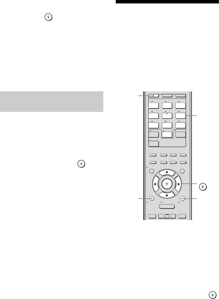
60US
6Press V/v repeatedly to select
the preset channel you want,
then press .
Preset channels from 1 to 30 are available,
and a default channel is preset for all the
preset channels when you purchase the
receiver.
The selected channel is registered as the
preset channel you selected in step 3.
7Repeat steps 3 to 6 to preset
another channel.
1Repeat steps 1 and 2 of
“Presetting channels using the
preset numbers” (page 59).
2Press V/v repeatedly to select
the preset number from the
preset list, then press .
You can select stored preset channels
from 1 to 30.
Notes
• The channel information you have preset may be
changed if SIRIUS Satellite Radio Inc. change
their channel programming.
• When the “Category Mode” screen is displayed,
press TOOLS/OPTIONS, then press V/v
repeatedly to select “Preset Mode”.
Restricting access to
specific channels
(Parental Lock)
You can restrict access to certain channels
using your own lock code. The lock code is set
to “0000” as the default.
Change the lock code before you use this
function for the first time. See “To change the
lock code (Lock Code)” (page 61).
1Select a channel you want to
lock using Category Mode
(page 58) or Direct Tuning
(page 59).
2Press TOOLS/OPTIONS.
The option menu appears.
3Press V/v repeatedly to select
“Parental Lock”, then press
or b.
Selecting the channel by using
the preset numbers 1 2 3
4 5 6
7 8 9
-/-- 0/10
ENT/MEM
2CH/
A.DIRECT A.F.D. MOVIE MUSIC
CLEAR
/
>10
SHIFT
RESOLUTION
.>
VIDEO 1 VIDEO 2 BD
SAT TV
HDMI 3HDMI 2HDMI 1
HDMI 4
SA-CD/
CD DMPORTTUNER
<
<
MENU
RETURN/
EXIT TOOLS/
OPTIONS
HOME
DISPLAY GUI MODE
O
DVD
INPUT
MODE SLEEP
NIGHT
MODE
TV AMP
– CATEGORY +
V/v/B/b,
TOOLS/
OPTIONS
SHIFT
Numeric
buttons
RETURN/
EXIT O

61US
Tuner Operations
4Press V/v repeatedly to select
“ON”, then press .
“Enter your 4-digit lock code.” appears.
5Press SHIFT, then press the
numeric buttons to enter your
4-digit lock code.
“The channel has been locked.” appears
and the Parental Lock is set.
To delete the numbers you have entered,
go back to step 2 by pressing RETURN/
EXIT O, and then repeat the procedure
above from step 2.
To change the lock code (Lock
Code)
1Select a channel you want to change
the lock code using Category Mode
(page 58) or Direct Tuning (page 59).
2Press TOOLS/OPTIONS.
The option menu appears.
3Press V/v repeatedly to select “Lock
Code”, then press .
“Enter your 4-digit lock code.” appears.
4Press SHIFT, then press the numeric
buttons to enter your 4-digit lock code.
“Enter a new lock code.” appears.
5Enter a new 4-digit lock code using the
numeric buttons.
“To confirm, enter your new lock code
again.” appears.
6Reenter the new lock code with the
numeric buttons.
“The lock code has been changed.”
appears.
To listen to the locked channels
1Select a locked channel you want to
listen to using Direct Tuning (page 59).
“Enter your 4-digit lock code.” appears.
2Press SHIFT, then press the numeric
buttons to enter your 4-digit lock code.
The channel is tuned in.
To cancel the Parental Lock
1Select a channel you want to unlock
using Direct Tuning (page 59).
2Press TOOLS/OPTIONS.
The option menu appears.
3Press V/v repeatedly to select
“Parental Lock”, then press or b.
4Press V/v repeatedly to select “OFF,”
then press .
“Enter your 4-digit lock code.” appears.
5Press SHIFT, then press the numeric
buttons to enter your 4-digit lock code.
“The channel has been unlocked.” appears
and the channel is unlocked.
Notes
• When you select a channel using Category Mode,
locked channels are skipped.
• When the receiver is reset to the factory settings,
the lock code returns to the default (0000), but the
Parental Lock settings are not removed.
• You cannot preset locked channels. If you set the
Parental Lock for a preset channel, the preset
information for that channel returns to the default.
• You cannot set the Parental Lock for channel 0 and
channel 184.
continued

62US
SIRIUS Satellite Radio message list
* “CALL 888” and “539-SIRI” appears on the display alternately.
Message
appears on
TV screen
[Display]
Explanation Remedies
Antenna
[ANTENNA]
The antenna is not connected
properly.
Check the connection between the SiriusConnect
Home tuner and the antenna.
Acquiring
[ACQUIRING]
The receiving condition is not
good.
Try moving the antenna to another location.
For details about the antenna location, refer to the
operating instructions supplied with the SiriusConnect
Home tuner.
UNSUB CH
[CALL 888,
539-SIRI]*
You have not subscribed for the
selected channel.
—
SR Tuner
[SR TUNER]
The SiriusConnect Home tuner is
not connected properly.
Check all the connections, and then turn the system on
again. Also make sure if the AC adaptor supplied with
the SiriusConnect Home tuner is connected to a wall
socket.
Invalid
[INVALID]
You have entered an invalid
channel number.
The channel to be tuned-in is void due to the change
by the broadcast service, or the receiving condition is
not good.
Locked CH
[LOCKED CH]
The selected channel is locked. —
SUB UPDT
[SUB UPDT]
The subscription information has
been updated.
—
Updating
[UPDATING]
Channel information is being
updated.
—
FW UPDT
[FW UPDT]
The SiriusConnect Home tuner
firmware is being updated.
—
– – – – There is no text information in the
channel.
This is not an error. The text information may not be
displayed depending on the system condition, for
example, right after the system has received a channel.
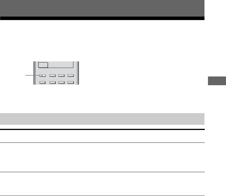
63US
Enjoying Surround Sound
Playing back with 2-channel sound
You can switch the output sound to 2-channel sound regardless of the recording formats of the
software you are using, the playback component connected, or the sound field settings of the
receiver.
Press 2CH/A.DIRECT repeatedly to select the 2-channel sound mode of the
sound output you want.
Notes
• When headphones are connected, “HP (Direct)” appears on the TV screen.
• You cannot select “Analog Direct” when you select DVD, DMPORT and HDMI 1–4 as input.
Enjoying Surround Sound
2CH/
A.DIRECT A.F.D. MOVIE MUSIC
RESOLUTION
HDMI 4
INPUT
MODE SLEEP
NIGHT
MODE
2CH/
A.DIRECT
Types of 2CH mode
2CH mode
(appears on TV screen)
Effect
2 CHANNEL STEREO
[2ch stereo]
The receiver outputs the sound from the front left/right speakers only. There is
no sound from the subwoofer.
Standard 2 channel stereo sources completely bypass the sound field processing
and multi channel surround formats are downmixed to 2 channel (except LFE
signals).
ANALOG DIRECT
[Analog Direct]
You can switch the audio of the selected input to 2 channel analog input. This
function enables you to enjoy high quality analog sources.
When using this function, only the volume and front speaker level can be
adjusted.
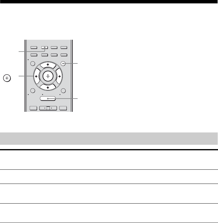
64US
Playing back with multi-channel surround
The Auto Format Direct (A.F.D.) mode allows you to listen to higher fidelity sound and select the
decoding mode for listening to a 2 channel stereo sound as multi channel sound.
Press A.F.D. repeatedly to select the A.F.D. mode you want.
Types of A.F.D. mode
2CH/
A.DIRECT A.F.D. MOVIE MUSIC
RESOLUTION
.>
<
<
MENU
RETURN/
EXIT TOOLS/
OPTIONS
HOME
DISPLAY GUI MODE
O
INPUT
MODE SLEEP
NIGHT
MODE
– CATEGORY +
V/v/B/b,
GUI MODE
MENU
A.F.D.
A.F.D. mode
[appears on TV screen]
Multi channel
audio after
decoding
Effect
A.F.D. AUTO
[A.F.D. Auto]
(Detecting
automatically)
Presets the sound as it was recorded/encoded without adding
any surround effects.
ENHANCED
SURROUND MODE
[Enhanced Sur]
– You can select the surround sound effect you want. For
details, see “Setting a multi channel surround sound effect”
(page 65).
MULTI STEREO
[Multi Stereo]
(Multi Stereo) Outputs 2 channel left/right signals from all speakers.
However, sound may not be output from certain speakers
depending on the speaker settings.

65US
Enjoying Surround Sound
Notes
• This function does not work in the following cases.
– DTS-HD signals with a sampling frequency of
more than 48 kHz are being received.
– Dolby TrueHD signals with a sampling
frequency of more than 48 kHz are being
received.
– “Analog Direct” is being used.
• The beginning of the sound stream may be dropped
out when Neural-THX® processing is turned on or
off.
Tips
• You can identify the encoding format of DVD
software, etc., by looking at the logo on the
package.
• When a multi channel signal is input, only Dolby
Pro Logic IIx decoding is effective.
• Neural-THX is effective when 2 channel or 5.1
channel signals are input.
If you connect a subwoofer
This receiver will generate a low frequency
signal for output to the subwoofer when there
is no LFE signal, which is a low-pass sound
effect output to a subwoofer from a 2 channel
signal. However, the low frequency signal is
not generated for “Neo:6 Cinema” or “Neo:6
Music” when all speakers are set to “Large”.
In order to take full advantage of the Dolby
Digital bass redirection circuitry, we
recommend setting the subwoofer’s cut off
frequency as high as possible.
1Start playing a sound source
you want to listen to (CD, DVD,
etc.).
2Press GUI MODE.
After “MENU ON” appears on the
display for a while, “GUI” appears and
the GUI menu appears on the TV screen.
Press MENU if the GUI menu does not
appear on the TV screen.
3Press V/v repeatedly to select
“Settings” then press or b.
The Settings menu list appears on the TV
screen.
4Press V/v repeatedly to select
“Surround”, then press or
b.
5Press V/v repeatedly to select
“E.Sur Mode”, then press .
The menu for surround sound effect
appears.
6Press V/v repeatedly to select
the A.F.D. mode you want, then
press .
Setting a multi channel
surround sound effect

66US
* You can select “Pro Logic II” when there is no surround back speaker on the “SP Pattern” menu, or you can
select “Pro Logic IIx” when there is a surround back speaker. You cannot select both settings at the same time.
Types of enhanced surround mode
Enhanced
surround mode
[appears on TV
screen]
Multi channel
audio after
decoding
Effect
PRO LOGIC II*
[Pro Logic II]
5-channel signals Performs Dolby Pro Logic II mode decoding. A source recorded
in 2 channel format is decoded into 5.1 channels. This setting is
ideal for movies encoded in Dolby Surround. In addition, this
mode can reproduce sound in 5.1 channel system for watching
videos of overdubbed or old movies.
PRO LOGIC IIx*
[Pro Logic IIx]
7-channel signals Performs Dolby Pro Logic IIx mode decoding. A source recorded
in 2 channel or 5.1 channel format is decoded into 7.1 channels.
This setting is ideal for movies encoded in Dolby Surround. In
addition, this mode can reproduce sound in 7.1 channel system for
watching videos of overdubbed or old movies.
NEO:6 CINEMA
[Neo:6 Cinema]
7-channel signals Performs DTS Neo:6 Cinema mode decoding. A source recorded
in 2 channel format is decoded into 7 channels.
NEO:6 MUSIC
[Neo:6 Music]
7-channel signals Performs DTS Neo:6 Music mode decoding. A source recorded in
2 channel format is decoded into 7 channels. This setting is ideal
for normal stereo sources such as CDs.
NEURAL-THX®
[Neural-THX]
7-channel signals Next generation of Neural-THX® Surround. In addition to stereo
enhancement processing and pure discrete 5.1 surround sound,
now capable of full 360° 7.1 surround sound playback from
Neural-THX® Surround encoded content.
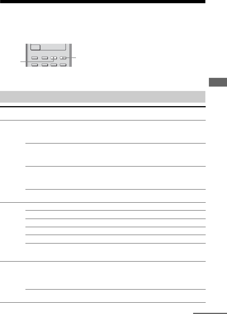
67US
Enjoying Surround Sound
Enjoying a surround effect for music/movie
You can take advantage of surround sound simply by selecting one of the receiver’s preprogrammed
sound fields. They bring the exciting and powerful sound of movie theaters and concert halls into
your home.
Press MUSIC or MOVIE repeatedly to select the surround effect you want
for music or movie.
a)You can only select this sound field if the headphones are connected to the receiver.
Types of music/movie mode
Sound
field for
Sound field
[appears on TV screen]
Effect
Movie CINEMA STUDIO EX A DCS
[Cinema St EX A]
Reproduces the sound characteristics of the Sony Pictures
Entertainment “Cary Grant Theater” cinema production
studio. This is a standard mode, great for watching almost
any type of movie.
CINEMA STUDIO EX B DCS
[Cinema St EX B]
Reproduces the sound characteristics of the Sony Pictures
Entertainment “Kim Novak Theater” cinema production
studio. This mode is ideal for watching science-fiction or
action movies with lots of sound effects.
CINEMA STUDIO EX C DCS
[Cinema St EX C]
Reproduces the sound characteristics of the Sony Pictures
Entertainment scoring stage. This mode is ideal for watching
musicals or films where orchestra music is featured in the
soundtrack.
VIRTUAL MULTI DIMENSION
DCS [V.M. Dimension]
Creates many virtual speakers from a single pair of actual
surround speakers.
Music HALL [Hall] Reproduces the acoustics of a classical concert hall.
JAZZ CLUB [Jazz Club] Reproduces the acoustics of a jazz club.
LIVE CONCERT [Live Concert] Reproduces the acoustics of a 300-seat live house.
STADIUM [Stadium] Reproduces the feeling of a large open-air stadium.
SPORTS [Sports] Reproduces the feeling of sports broadcasting.
PORTABLE AUDIO
ENHANCER
[Portable Audio]
Reproduces a clear enhanced sound image from your
portable audio device. This mode is ideal for MP3 and other
compressed music.
Headphonea) HEADPHONE (2CH)
[HP (2CH)]
This mode is selected automatically if you use headphones
when 2ch Stereo mode (page 63)/A.F.D. mode (page 64) is
selected. Standard 2 channel stereo sources completely
bypass the sound field processing and multi channel surround
formats are downmixed to 2 channels (except LFE signals).
HEADPHONE (DIRECT)
[HP (Direct)]
Outputs the analog signals without processing by the
equalizer, sound field, etc.
2CH/
A.DIRECT A.F.D. MOVIE MUSIC
RESOLUTION
HDMI 4
INPUT
MODE SLEEP
NIGHT
MODE
MUSIC
MOVIE
continued
68US
Notes
• The sound fields for music and movies do not work
in the following cases.
– PCM signals with a sampling frequency of more
than 48 kHz are being received.
– DTS 96/24 signals are being received.
– DTS-HD signals with a sampling frequency of
more than 48 kHz are being received.
– Dolby TrueHD signals with a sampling
frequency of more than 48 kHz are being
received.
– Signals with a sampling frequency of more than
48 kHz are being received.
– The multi channel PCM signals are received via
an HDMI IN jack with a sampling frequency
more than 48 kHz.
• When one of the sound fields for music is selected,
no sound is output from the subwoofer if all the
speakers are set to “Large” on the Speaker Settings
menu. However, the sound will be output from the
subwoofer if
– the digital input signal contains LFE signals.
– the front and surround speakers are set to
“Small”.
– the sound field for movie is selected.
– “Portable Audio” is selected.
• The effects provided by the virtual speakers may
cause increased noise in the playback signal.
• When listening with sound fields that employ the
virtual speakers, you will not be able to hear any
sound coming directly from the surround speakers.
Tips
• You can identify the encoding format of DVD
software, etc., by looking at the logo on the
package.
• Sound fields with DCS marks use DCS
technology. See “Glossary” (page 122).
To turn off the sound field for
movie/music
Press 2CH/A.DIRECT or A.F.D.
69US
Enjoying Surround Sound
Digital audio formats that this receiver can decode depend on digital audio input jacks for the
components connected.
This receiver supports the following audio formats.
a)Audio signals are output in another format if the playback component does not correspond to the format. For
details, refer to the operating instructions of the playback component.
b)Signals with a sampling frequency of more than 96 kHz are played back at 96 kHz.
Digital audio formats supported by the receiver
Audio format Maxi mum number
of channels
Connection of the playback component and
the receiver
COAXIAL/OPTICAL HDMI
Dolby Digital 5.1ch aa
Dolby Digital EX 6.1ch aa
Dolby Digital Plusa) 7.1ch × a
Dolby TrueHDa) 7.1ch × a
DTS 5.1ch aa
DTS-ES 6.1ch aa
DTS 96/24 5.1ch aa
DTS-HD
High Resolution Audioa) 7.1ch ×a
DTS-HD
Master Audioa)b) 7.1ch ×a
Multi channel Linear PCMa) 7.1ch × a
70US
Resetting sound fields to
the initial settings
Be sure to use the buttons on the receiver for
this operation.
1Press ?/1 to turn off the
receiver.
2While holding down MUSIC,
press ?/1.
“S.F. CLEAR” appears on the display and
all sound fields are reset to their initial
setting.
Using the setting menu
You can adjust various settings for speakers,
surround effects, etc. using the setting menu.
To display the menu of the receiver on the TV
screen, make sure that the receiver is in “GUI
MODE” by following the steps in
“7: Displaying the GUI menu on the TV
screen” (page 37).
1Press GUI MODE.
After “MENU ON” appears on the
display for a while, “GUI” appears and
the GUI menu appears on the TV screen.
Press MENU if the GUI menu does not
appear on the TV screen.
?/1
MASTER VOLUME
SPEAKERS
PHONES 2 CH/
A.DIRECT A.F.D. MOVIE MUSIC INPUT MODE DIMMER DISPLAY
VIDEO 2 IN
VIDEO L AUDIO R
AUTO CAL MIC
MULTI CHANNEL DECODING
INPUT SELECTOR
MUTING
?/1
MUSIC
Amplifier Operations
2CH/
A.DIRECT A.F.D. MOVIE MUSIC
RESOLUTION
.>
<
<
MENU
RETURN/
EXIT TOOLS/
OPTIONS
HOME
DISPLAY GUI MODE
O
INPUT
MODE SLEEP
NIGHT
MODE
– CATEGORY +
V/v/B/b,
GUI MODE
MENU
RETURN/
EXIT O
Input
Music
Video
VIDEO 1
VIDEO 2
BD
DVD
SAT
71US
Amplifier Operations
2Press V/v repeatedly to select
“Settings”, then press or b,
to enter the menu mode.
The setting menu list appears on the TV
screen.
3Press V/v repeatedly to select
the menu item you want, then
press or b.
Example: When you select “Auto Cal.”.
4Press V/v repeatedly to select
the parameter you want, then
press or b.
To return to the previous screen
Press RETURN/EXIT O.
To exit the menu
Press MENU.
Setting menu list
AM
AM
SR
SR
Setting
Auto Cal.
Speaker
Surround
EQ
Audio
Setting
Speaker
Surround
EQ
Audio
Auto Cal.
Menu Description
Auto Cal. Sets the speaker level or
distance and makes the
measurement automatically
(page 72).
Speaker Sets the speaker position and
impedance manually (page
73).
Surround Adjusts the sound field
(surround effect) you choose
(page 77).
EQ Adjusts the equalizer (bass/
treble sound) (page 78).
Audio Sets various sound items
(page 78).
Video Adjusts the resolution of
analog video signals (page
79).
HDMI Makes settings for sound/
images from components
connected to the HDMI jacks
(page 81).
S-AIR Makes settings for S-AIR
operations (page 82).

72US
Settings for the Auto
Calibration
(Auto Calibration menu)
You can make settings for the Auto
Calibration function to suit your preference.
xAuto Cal. Start (Auto Calibration
start)
Lets you perform Auto Calibration. For
details, see “Performing Auto Calibration”
(page 41).
xAuto Cal. Type (Calibration type)
Lets you select the Auto Calibration type for
each seating position. For details, see step 4 of
“Confirming/saving the measurement results”
(page 42).
Note
You can select this parameter only when you have
performed the Auto Calibration and saved the
measurement result.
xPosition (Position)
You can select the seating position you want
and register the measurement results of the
Auto Calibration for that seating position.
You can register 3 patterns as Position 1, 2,
and 3, depending on the listening position,
listening environment, and measurement
conditions.
To register more than one set of
settings for the listening
environment
You can select the seating position you want
and register the measurement results of the
Auto Calibration for that seating position.
1Press V/v repeatedly to select
“Position”, then press or b.
2Press V/v repeatedly to select the
position (Position 1, 2, 3) for which you
want to register the measurement
result, then press .
3Press V/v repeatedly to select “Auto
Cal. Start”, then press or b.
The measurement results is registered as
the position you selected in step 2.
4Press to select “START”.
5Repeat step 1 to 3 to register another
seating position.
To select the registered seating
position
1Press V/v repeatedly to select
“Position”, then press .
2Press V/v repeatedly to select the
position (Position 1, 2, 3) you want,
then press .
The registered seating position is selected.
xName Input (Naming position)
You can rename the position name.
To name the position name
1Select the “Position” for which you want
to name.
2Press V/v repeatedly to select “Name
Input”, then press .
3Press V/v/B/b to select a character,
then press .
The name you entered is registered.
Auto Calibration menu
parameter

73US
Amplifier Operations
Setting for the speaker
(Speaker Settings menu)
You can adjust each speaker manually.
You can also adjust the speaker levels after the
Auto Calibration is completed.
Note
The speaker settings are only for the current seating
position.
xSP Pattern (Speaker pattern)
Select “SP Pattern” according to the speaker
system which you are using. You do not need
to select the speaker pattern after Auto
Calibration.
To select the speaker pattern
1Press V/v repeatedly to select
“SP Pattern”, then press or b.
The “SP Pattern” screen appears.
2Press V/v repeatedly to select the
speaker pattern you want, then press
.
3Press RETURN/EXIT O.
xSB Assign (Surround back
speaker assign)
You can make settings for the surround back
speaker(s). Before you change “SB Assign” to
“BI-AMP” or “Speaker B”, be sure you have
set “SP Pattern” to a setting without surround
back speakers.
• Speaker B
If you connect an additional front speaker
system to the SPEAKERS SURROUND
BACK/FRONT B/BI-AMP terminals, select
“Speaker B” (page 38).
•BI-AMP
If you connect front speakers in a bi-
amplifier configuration, select “BI-AMP”
(page 113).
•OFF
If you have not connected surround back
speakers, select “OFF”.
Note
Set “SB Assign” to “OFF”, then connect the
surround back speakers to this receiver when you
want to change the connection from a bi-amplifier
connection or front speakers B connection to a
surround back speakers connection. Re-set up the
speakers after you connect the surround back
speakers. See “9: Calibrating the appropriate
speaker settings automatically (Auto Calibration)”
(page 40).
xManual Setup (Manual setup)
You can adjust each speaker manually on the
“Manual Setup” screen. You can also adjust
the speaker levels after the Auto Calibration is
completed.
To adjust the speaker level
You can adjust each speaker’s level (front left/
right, center, surround left/right, surround
back left/right, subwoofer).
1Press V/v/B/b repeatedly to select the
speaker on the screen for which you
want to adjust the level, then press .
2Press B/b repeatedly to select “Lvl:”.
3Press V/v repeatedly to set the level of
the selected speaker, then press .
Speaker Settings menu
parameter
continued

74US
Note
When one of the sound fields for music is selected,
no sound is output from the subwoofer if all the
speakers are set to “Large”. However, the sound will
be output from the subwoofer if
– the digital input signal contains LFE signals.
– the front and surround speakers are set to “Small”.
– the sound field for movie is selected.
– “Portable Audio” is selected.
To adjust the distance from the
seating position to each
speaker
You can adjust the distance from the listening
position to each speaker (front left/right,
center, surround left/right, surround back left/
right, subwoofer).
1Press V/v/B/b repeatedly to select the
speaker on the screen for which you
want to adjust the distance from the
seating position, then press .
2Press B/b repeatedly to select “Dist:”.
3Press V/v repeatedly to set the
distance of the selected speaker, then
press .
You can adjust the distance from 3 feet
3 inches to 32 feet 9 inches (1.00 meter to
10.00 meters) in 1 inch (0.01 meter) steps.
To adjust the size of each
speaker
You can adjust each speaker’s (front left/right,
center, surround left/right, surround back left/
right) size.
1Press V/v/B/b repeatedly to select the
speaker on the screen for which you
want to adjust the size, then press .
2Press B/b repeatedly to select “Size:”.
3Press V/v repeatedly to set the size of
the selected speaker, then press .
•Large
If you connect large speakers that will
effectively reproduce bass frequencies,
select “Large”. Normally, select “Large”.
•Small
If the sound is distorted, or you feel a lack
of surround effects when using multi
channel surround sound, select “Small” to
activate the bass redirection circuitry and
output the bass frequencies of each
channel from the subwoofer or other
“Large” speakers.
Tips
• The “Large” and “Small” settings for each speaker
determine whether the internal sound processor
will cut the bass signal from that channel.
When the bass is cut from a channel, the bass
redirection circuitry sends the corresponding bass
frequencies to the subwoofer or other “Large”
speakers.
However, since bass sound has a certain amount of
directionality, it is best not to cut it, if possible.
Therefore, even when using small speakers, you
can set them to “Large” if you want to output the
bass frequencies from that speaker. On the other
hand, if you are using a large speaker, but prefer
not to have bass frequencies output from that
speaker, set it to “Small”.
If the overall sound level is lower than you prefer,
set all speakers to “Large”. If there is not enough
bass, you can use the equalizer to boost the bass
levels.
• The surround back speakers will be set to the same
setting as that of the surround speakers.
• When the front speakers are set to “Small”, the
center, surround, and surround back speakers are
also automatically set to “Small”.
• If you do not use the subwoofer, the front speakers
are automatically set to “Large”.

75US
Amplifier Operations
xCrossover Freq
(Speaker crossover frequency)
Lets you set the bass crossover frequency of
speakers that the speaker size has been set to
“Small” in the Speaker Settings menu.
Measured speaker crossover frequency is set
for each speaker after the Auto Calibration.
1Press B/b repeatedly to select
the speaker on the screen you
want to adjust.
2Press V/v repeatedly to adjust
the value, then press .
xTest Tone (Test tone)
You can select the test tone type on the “Test
Tone” screen.
Tips
• To adjust the level of all speakers at the same time,
press MASTER VOL +/–. You can also use
MASTER VOLUME on the receiver.
• The adjusted value is shown on the TV screen
during adjustment.
To output test tone from each
speaker
You can output test tone from the speakers in
sequence.
1Press B/b repeatedly to select “Test
Tone”, then press .
The “Test Tone” screen appears.
2Press V/v repeatedly to adjust the
parameter, then press .
•OFF
• AUTO
The test tone is output from each speaker
in sequence.
• FL, CNT, FR, SR, SBR, SBL, SB, SL,
SW
You can select which speakers will output
the test tone.
3Press V/v repeatedly to adjust the
speaker level, then press .
To output test tone from
adjacent speakers
You can output test tone from adjacent
speakers so that you can adjust the balance
between the speakers.
1Press B/b repeatedly to select “Phase
Noise”, then press .
The “Phase Noise” screen appears.
2Press V/v repeatedly to adjust the
parameter, then press .
•OFF
• FL/SR, SL/FL, SB/SL, SBL/SL, SR/SB,
SBR/SBL, SR/SBR, SR/SL, FR/SR,
FR/SL, CNT/FR, FL/CNT, FL/FR
Lets you output the test tone sequentially
from adjacent speakers.
Some items may not be displayed,
depending on the setting of the speaker
pattern.
3Press V/v repeatedly to adjust the
speaker level, then press .
To output the source sound
from adjacent speakers
You can output the source sound from
adjacent speakers so that you can adjust the
balance between the speakers.
1Press B/b repeatedly to select “Phase
Audio”, then press .
The “Phase Audio” screen appears.
2Press V/v repeatedly to adjust the
parameter, then press .
•OFF
• FL/SR, SL/FL, SB/SL, SBL/SL, SR/SB,
SBR/SBL, SR/SBR, SR/SL, FR/SR,
FR/SL, CNT/FR, FL/CNT, FL/FR
Lets you output front 2 channel source
sound (instead of the test tone)
sequentially from adjacent speakers.
Some items may not be displayed,
depending on the setting of the speaker
pattern.
3Press V/v repeatedly to adjust the
speaker level, then press .
continued
76US
When a test tone is not output
from the speakers
• The speaker cords may not be connected
securely. Check to see if they are connected
securely and cannot be disconnected by
pulling on them slightly.
• The speaker cords may have the short-circuit
problem.
When a test tone is output from
a different speaker than the
speaker displayed on the TV
screen
The speaker pattern to the connected speaker
is not set up correctly. Make sure the speaker
connection and the speaker pattern match.
xD.Range Comp
(Dynamic range compression)
Lets you compress the dynamic range of the
soundtrack. This may be useful when you want
to watch movies at low volumes late at night.
Dynamic range compression is possible with
Dolby Digital sources only.
•MAX
The dynamic range is compressed
dramatically.
•STD
The dynamic range is compressed as
intended by the recording engineer.
• AUTO
The dynamic range is applied automatically
with Dolby TrueHD source or other source
is set to “OFF”.
•OFF
The dynamic range is not compressed.
Tips
• Dynamic range compressor lets you compress the
dynamic range of the soundtrack based on the
dynamic range information included in the Dolby
Digital signal.
• “STD” is the standard setting, but it only enacts
light compression. Therefore, we recommend
using the “MAX” setting. This greatly compresses
the dynamic range and lets you view movies late at
night at low volumes. Unlike analog limiters, the
levels are predetermined and provide a very natural
compression.
xDistance Unit (Distance unit)
Lets you select the unit of measure for setting
distances.
• FEET
The distance is displayed in feet.
• METER
The distance is displayed in meters.

77US
Amplifier Operations
Settings for the surround
sound
(Surround Settings menu)
You can adjust the sound effect on the
“S.F. Select” screen.
Note
The setup items you can adjust on each menu vary
depending on the sound field.
xS.F. Select (Sound field select)
You can select the surround sound field and
adjust the effect level on the “S.F. Select”
screen.
For details on the sound field, see “Enjoying
Surround Sound” (page 63).
To select the surround sound
field
1Press V/v repeatedly to select
“S.F. Select”, then press .
2Press V/v repeatedly to select
surround sound you want, then press
.
To adjust the effect level
1Press V/v repeatedly to select
“S.F. Select”, then press or b.
2Press V/v repeatedly to select
surround sound you want, then press
.
Note
Effect Level adjustment is valid only when
“Cinema Studio EX DCS ” is selected.
3Press V/v repeatedly to select “Effect
Level”, then press or b.
4Press V/v repeatedly to select effect
level you want, then press .
• 50%
• 80%
• 100%
• 150%
xE.Sur Mode (Enhanced surround
mode)
You can select the decoding mode for the
sound field.
For details on the decoding modes available,
see “Setting a multi channel surround sound
effect” (page 65).
• Pro Logic II
Performs Dolby Pro Logic II decoding. A
source recorded in 2 channel format is
decoded into 5.1 channels.
• Pro Logic IIx
Performs Dolby Pro Logic IIx decoding. A
source recorded in 2 channel or 5.1 channel
format is decoded into 7.1 channels.
•Neo:6 Cinema
Performs DTS Neo:6 Cinema mode
decoding. A source recorded in 2 channel
format is decoded into 7 channels.
•Neo:6 Music
Performs DTS Neo:6 Music mode decoding.
A source recorded in 2 channel format is
decoded into 7 channels. This setting is ideal
for normal stereo sources such as CDs.
•Neural-THX
Next generation of Neural-THX® Surround.
In addition to stereo enhancement
processing and pure discrete 5.1 surround
sound, now capable of full 360° 7.1 surround
sound playback from Neural-THX®
surround encoded content.
Note
You can select “Pro Logic II” when there is no
surround back speaker on the “SP Pattern” menu, or
you can select “Pro Logic IIx” when there is a
surround back speaker. You cannot select both
settings at the same time.
Surround Settings menu
parameters
78US
Settings for the EQ
(EQ menu)
You can use the following parameters to adjust
the tonal quality (bass/trebel level) of front
speakers.
Notes
• This function does not work in the following cases.
– Sound Field is set to “Analog Direct”.
– PCM signals with a sampling frequency of more
than 96 kHz are being received.
– Dolby TrueHD signals with a sampling
frequency of more than 96 kHz are being
received.
• If the equalizer is adjusted while the receiver is
receiving signals with a sampling frequency of
more than 96 kHz, the signals will always be
played back at 96 kHz.
To adjust the equalizer on the
EQ screen
1Press B/b repeatedly to select “Bass”
or “Treble”.
2Press V/v repeatedly to adjust the gain,
then press .
Settings for the audio
(Audio Settings menu)
You can make settings for the audio to suit
your preference.
xA/V Sync (Synchronizes audio
with video output)
Lets you delay the output of audio to minimize
the time gap between audio output and visual
display. You can adjust the delay from 0 ms to
300 ms in 10 ms steps.
Notes
• This parameter is useful when you use a large LCD
or plasma monitor or a projector.
• This parameter is not valid when “Analog Direct”
is being used.
xDual Mono (Digital broadcast
language selection)
Lets you select the language you want to listen
to during digital broadcast. This feature only
functions for Dolby Digital sources.
•Main/Sub
Sound of the main language will be output
through the front left speaker and sound of
the sub language will be output through the
front right speaker simultaneously.
•Main
Sound of the main language will be output.
•Sub
Sound of the sub language will be output.
Level
(dB)
Bass Treble
Frequency
(Hz)
Audio Settings menu parameters

79US
Amplifier Operations
xDec. Priority (Digital audio input
decoding priority)
Lets you specify the input mode for the digital
signal input to the HDMI IN jack.
•PCM
When signals from the HDMI IN jack are
selected, only PCM signals are output from
the connected player. To prevent interruption
when playback starts, set to “PCM”. When
signals in any other format are received, set
this item to “AUTO”.
• AUTO
Automatically switches the input mode
between DTS, Dolby Digital, or PCM.
Note
Even when “Dec. Priority” is set to “PCM”, the
sound may be interrupted at the very beginning of
the first track depending on the CD being played
back.
Settings for the video
(Video Settings menu)
You can make settings for video.
xResolution
(Converting video signals)
Lets you convert the resolution of analog video
input signals.
•DIRECT
Lets you output analog video input signals
without conversion.
• AUTO
• 480/576i
• 480/576p
•720p
• 1080i
For details, see “In the video input/output
conversion table classified by the menu
settings” (page 80).
Tip
You can also press RESOLUTION repeatedly to
convert analog video input signals.
Each time you press the button, the resolution of the
output signals will be changed.
Video Settings menu parameters
continued

80US
In the video input/output conversion table classified by the menu
settings
a: Video signals are up-converted and output through the video converter.
f: The same type of signal as that of the input signal is output. Video signals are not converted.
X: Video signals are not output.
a)The resolution is set automatically, depending on the connected TV.
b)When the TV is connected to jacks other than the HDMI jacks, 480/576i signals are output when “Resolution”
is set to “AUTO”.
c)480/576p signals are output even if 480/576i is set.
d)Video signals without copyright protection are output based on the settings menu. Video signals with
copyright protection are output as 480p.
Notes
• Video signals are not output from the COMPONENT VIDEO MONITOR OUT or MONITOR VIDEO OUT
jacks when the TV, etc., is connected to the HDMI OUT jack.
• If you select a resolution that the connected TV does not support in the “Resolution” menu, the images from
the TV cannot be output correctly.
• Converted HDMI image output signals do not support “x.v.Color”.
• Converted HDMI image output signals do not support Deep Color.
• When HDMI OUT jack is connected, there is no up-converted video signal output from COMPONENT
VIDEO MONITOR OUT jacks. The COMPONENT VIDEO MONITOR OUT jacks have the component
signal direct output only.
• This receiver do not support 1080p input signals. You cannot up-convert the video signals to 1080p using this
receiver.
xComp.Dec. (Component video decoder)
If the image is distorted when you connect to video game, set “Comp. Dec.” to “ON”. This setting
is only applicable for component video input signals.
•ON
•OFF
“Resolution”
menu setting
HDMI OUT
jack
COMPONENT
VIDEO
MONITOR OUT
jacks
MONITOR
VIDEO OUT
jack
DIRECT Component video XfX
Video XXf
AUTO (initial
setting)
Component video aa) ab) X
Video aa) ab) f
480/576i Component video ac) aX
Video ac) af
480/576p Component video aaX
Video aaf
720p, 1080i Component video aa
d) X
Video aa
d) f
Input signals
Output from

81US
Amplifier Operations
Settings for HDMI
(HDMI Settings menu)
You can make the required settings for
components connected to the HDMI jack.
xCtrl for HDMI (Control for HDMI)
Lets you turn the Control for HDMI function
on or off. For details, see “Preparing for the
“BRAVIA” Sync” (page 94).
•OFF
•ON
Note
When you set “Ctrl for HDMI” to “ON”, “Audio
Out” may be changed automatically.
xAudio Out (Setting HDMI audio
input)
Lets you set the audio output for HDMI from
the playback component connected to the
receiver via an HDMI connection.
•AMP
The HDMI audio signals from the playback
component is only output to the speakers
connected to the receiver. Multi channel
sound can be played back as it is.
Note
Audio signals are not output from the TV speakers
when “Audio Out” is set to “AMP”.
• TV+AMP
The sound is output from TV’s speaker and
the speakers connected to the receiver.
Notes
• The sound quality of the playback component
depends on the TV’s sound quality, such as the
number of channels, and the sampling
frequency, etc. When the TV has stereo
speakers, the sound output from the receiver is
also stereo as that of the TV, even if you play
back multi channel source.
• When you connect the receiver to an image
display component (projector, etc.), sound may
not be output from the receiver. In this case,
select “AMP”.
• When you select the input that you have
assigned the HDMI input, sound does not output
from the TV.
xSW Level (Subwoofer level for
HDMI)
Lets you set the level of the subwoofer to 0 dB
or +10 dB when PCM signals are input via an
HDMI connection. You can set the level for
each HDMI input independently.
• AUTO
The subwoofer level is automatically set to
0 dB or +10 dB depending on the sampling
frequency.
• +10 dB
•0 dB
HDMI Settings menu parameters
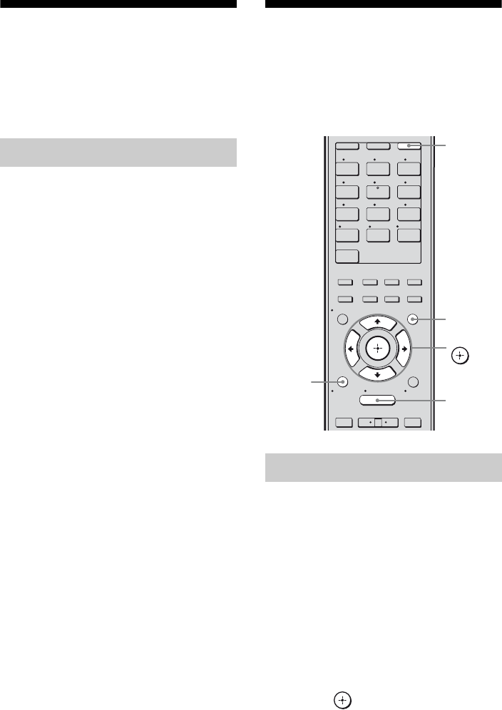
82US
Settings for the S-AIR
(S-AIR Settings menu)
You can make the required settings when you
have connect the S-AIR sub unit to the
EZW-T100 slot.
xS-AIR ID (S-AIR ID)
Lets you set the ID to match the S-AIR main
unit with S-AIR sub unit. For details, see
“Establishing sound transmission between the
S-AIR main unit and S-AIR sub unit (ID
setting)” (page 100).
xPairing (Pairing)
Lets you pair your S-AIR main unit with the
specific S-AIR sub unit. For details, see
“Pairing the S-AIR main unit with a specific S-
AIR sub unit (Pairing operation)” (page 102).
xS-AIR Mode (S-AIR mode)
You can enjoy the system’s sound in another
room by using the S-AIR receiver. For details,
see “Enjoying the system’s sound in another
room” (page 104).
xRF Change (RF change)
You can improve the transmission by
changing the channel. For details, see
“Changing the channel for better sound
transmission” (page 105).
xS-AIR Stby (S-AIR standby)
You can enjoy the S-AIR receiver while the
S-AIR main unit is in standby mode. For
details, see “Enjoying the S-AIR receiver
while the S-AIR main unit is in standby mode”
(page 107).
Operating without
connecting to a TV
You can operate this receiver using the display
even if you do not use a GUI when a TV is not
connected.
Press GUI MODE repeatedly to
select “MENU OFF”.
When “GUI” is displayed in the display, the
menu is set to display on the TV screen using
a GUI.
1Press AMP.
2Press MENU.
3Press V/v repeatedly to select
the menu you want.
4Press or b to enter the
menu.
S-AIR Settings menu parameters
Using the menu in the display
1 2 3
4 5 6
7 8 9
-/-- 0/10
ENT/MEM
2CH/
A.DIRECT A.F.D. MOVIE MUSIC
CLEAR
/
>10
SHIFT
RESOLUTION
.>
VIDEO 1 VIDEO 2 BD
SAT TV
HDMI 3HDMI 2HDMI 1
HDMI 4
SA-CD/
CD DMPORTTUNER
<
<
MENU
RETURN/
EXIT TOOLS/
OPTIONS
HOME
DISPLAY GUI MODE
O
DVD
INPUT
MODE SLEEP
NIGHT
MODE
TV AMP
– CATEGORY +
V/v/B/b,
GUI MODE
MENU
AMP
RETURN/
EXIT O

83US
Amplifier Operations
5Press V/v repeatedly to select
the parameter you want to
adjust.
6Press or b to enter the
parameter.
7Press V/v repeatedly to select
the setting you want.
8Press to enter the setting.
To return to the previous
display
Press B or RETURN/EXIT O.
To exit the menu
Press MENU.
Note
Some parameters and settings may appear dimmed
on the display. This means that they are either
unavailable or fixed and unchangeable.

84US
The following options are available in each menu. For details on navigating through menus, see
page 82.
Overview of the menus
Menu
[Display]
Parameters
[Display]
Settings Initial
setting
Auto Calibration
settings
[<AUTO CAL>]
Auto Calibration start
[A.CAL START]
Calibration type
[CAL TYPE]
FULL FLAT, ENGINEER,
FRONT REF, OFF
FULL FLAT
Position
[POSITION]
POS. 1, POS. 2, POS. 3 POS. 1
Naming position
[NAME IN]
For details, see “To name the position
name” (page 72).
Level settings
[<LEVEL>]
Test tone
[TEST TONE]
OFF, FIX xxxa), AUTO xxxa) OFF
Phase noiseb)
[P. NOISE]
OFF, FL/SR, SL/FL, SB/SL, SBL/SL,
SBR/SBL, SR/SB, SR/SBR, SR/SL,
FR/SR, FR/SL, FL/FR, CNT/FR,
FL/CNT
OFF
Phase audiob)
[P. AUDIO]
OFF, FL/SR, SL/FL, SB/SL, SBL/SL,
SBR/SBL, SR/SB, SR/SBR, SR/SL,
FR/SR, FR/SL, FL/FR, CNT/FR,
FL/CNT
OFF
Front left speaker levelb)
[FL LEVEL]
FL –10.0 dB to FL +10.0 dB
(0.5 dB per step)
FL 0.0 dB
Front right speaker levelb)
[FR LEVEL]
FR –10.0 dB to FR +10.0 dB
(0.5 dB per step)
FR 0.0 dB
Center speaker levelb)
[CNT LEVEL]
CNT –20.0 dB to CNT +10.0 dB
(0.5 dB per step)
CNT 0.0 dB
Surround left speaker levelb)
[SL LEVEL]
SL –20.0 dB to SL +10.0 dB
(0.5 dB per step)
SL 0.0 dB
Surround right speaker levelb)
[SR LEVEL]
SR –20.0 dB to SR +10.0 dB
(0.5 dB per step)
SR 0.0 dB
Surround back speaker levelb)
[SB LEVEL]
SB –20.0 dB to SB +10.0 dB
(0.5 dB per step)
SB 0.0 dB
Surround back left speaker
levelb)
[SBL LEVEL]
SBL –20.0 dB to SBL +10.0 dB
(0.5 dB per step)
SBL 0.0 dB
Surround back right speaker
levelb)
[SBR LEVEL]
SBR –20.0 dB to SBR +10.0 dB
(0.5 dB per step)
SBR 0.0 dB
Subwoofer levelb)
[SW LEVEL]
SW –20.0 dB to SW +10.0 dB
(0.5 dB per step)
SW 0.0 dB
Dynamic range compression
[D. RANGE]
COMP. MAX, COMP. STD,
COMP. AUTO, COMP. OFF
COMP. AUTO

85US
Amplifier Operations
Menu
[Display]
Parameters
[Display]
Settings Initial
setting
Speaker settings
[<SPEAKER>]
Speaker pattern
[SP PATTERN]
3/4.1, 3/4, 3/3.1, 3/3, 2/4.1, 2/4, 3/2.1,
3/2, 2/3.1, 2/3, 2/2.1, 2/2, 3/0.1, 3/0,
2/0.1, 2/0
3/4.1
Front speakers [FRT SP] LARGE, SMALL LARGE
Center speaker [CNT SP] LARGE, SMALL LARGE
Surround speakers
[SUR SP]
LARGE, SMALL LARGE
Surround back speaker assignc)
[SB ASSIGN]
SPK B, BI-AMP, OFF OFF
Front left speaker distanceb)
[FL DIST.]
FL 3’3” to FL 32’9”
(FL 1.00 m to FL 10.00 m)
(1 inch (0.01 m) step)
FL 9’10”
(3.00 m)
Front right speaker distanceb)
[FR DIST.]
FR 3’3” to FR 32’9”
(FR 1.00 m to FR 10.00 m)
(1 inch (0.01 m) step)
FR 9’10”
(3.00 m)
Center speaker distanceb)
[CNT DIST.]
CNT 3’3” to CNT 32’9”
(CNT 1.00 m to CNT 10.00 m)
(1 inch (0.01 m) step)
CNT 9’10”
(3.00 m)
Surround left speaker distanceb)
[SL DIST.]
SL 3’3” to SL 32’9”
(SL 1.00 m to SL 10.00 m)
(1 inch (0.01 m) step)
SL 9’10”
(3.00 m)
Surround right speaker distanceb)
[SR DIST.]
SR 3’3” to SR 32’9”
(SR 1.00 m to SR 10.00 m)
(1 inch (0.01 m) step)
SR 9’10”
(3.00 m)
Surround back speaker distanceb)
[SB DIST.]
SB 3’3” to SB 32’9”
(SB 1.00 m to SB 10.00 m)
(1 inch (0.01 m) step)
SB 9’10”
(3.00 m)
Surround back left speaker
distanceb)
[SBL DIST.]
SBL 3’3” to SBL 32’9”
(SBL 1.00 m to SBL 10.00 m)
(1 inch (0.01 m) step)
SBL 9’10”
(3.00 m)
Surround back right speaker
distanceb)
[SBR DIST.]
SBR 3’3” to SBR 32’9”
(SBR 1.00 m to SBR 10.00 m)
(1 inch (0.01 m) step)
SBR 9’10”
(3.00 m)
Subwoofer distanceb)
[SW DIST.]
SW 3’3” to SW 32’9”
(SW 1.00 m to SW 10.00 m)
(1 inch (0.01 m) step)
SW 9’10”
(3.00 m)
Distance unit
[DIST. UNIT]
FEET, METER FEET
Front speaker crossover
frequencyd)
[FRT CROSS]
CROSS 40 Hz to CROSS 200 Hz
(10 Hz step)
CROSS 120 Hz
Center speaker crossover
frequencyd)
[CNT CROSS]
CROSS 40 Hz to CROSS 200 Hz
(10 Hz step)
CROSS 120 Hz
Surround speaker crossover
frequencyd)
[SUR CROSS]
CROSS 40 Hz to CROSS 200 Hz
(10 Hz step)
CROSS 120 Hz
continued

86US
Menu
[Display]
Parameters
[Display]
Settings Initial
setting
Surround settings
[<SURROUND>]
Sound field selection
[S.F. SELECT]
For details, see “Enjoying Surround
Sound” (page 63).
A.F.D. AUTO
Enhanced surround mode
[E.SUR MODE]
PLIIb), PLIIxb), NEO6 CIN, NEO6
MUS, NEURAL-THX
PLIIx
Effect levele)
[EFFECT]
EFCT. 50%, EFCT. 80%, EFCT.
100%, EFCT. 150%
EFCT. 100%
EQ settings
[<EQ>]
Front speakers bass level
[BASS]
BASS –10 dB to BASS +10 dB
(1 dB per step)
BASS 0 dB
Front speakers treble level
[TREBLE]
TREBLE –10 dB to TREBLE +10 dB
(1 dB per step)
TREBLE 0 dB
Tuner settings
[<TUNER>]
FM station receiving mode
[FM MODE]
STEREO, MONO STEREO
Naming preset stations
[NAME IN]
For details, see “Naming preset
stations (Name Input)” (page 55).
Parental lockf)
[PARENTAL]
OFF, ON OFF
Lock code editf)
[CODE EDIT]
For details, see “Restricting access to
specific channels (Parental Lock)”
(page 60).
SIRIUS antenna aiming modef)
[SR ANT AIM]
For details, see “Checking receiving
conditions (Antenna Aiming)” (page
57).
SIRIUS radio IDf)
[SIRIUS ID]
For details, see “Checking the
SIRIUS Radio ID” (page 57).
Audio settings
[<AUDIO>]
Synchronizes audio with video
output
[A/V SYNC]
0 ms to 300 ms
(10 ms per step)
0 ms
Digital broadcast language
selection
[DUAL MONO]
MAIN/SUB, MAIN, SUB MAIN
Digital audio input decoding
priority
[DEC. PRIO.]
DEC. AUTO, DEC. PCM DEC. AUTO
Digital audio input assignment
[A. ASSIGN]
VIDEO 1 ? c BD OPT, SAT OPT, DVD COAX,
ANALOG
VIDEO 2 ? c
BD ? c
DVD ? c
SAT ? c
SA-CD/CD ? c

87US
Amplifier Operations
a)xxx represent a speaker channel (FL, FR, CNT, SL, SR, SB, SBL, SBR, SW).
b)Depends on the speaker pattern setting, some parameters or settings may not be available.
c)You can only select this parameter if “SP PATTERN” is not set to a setting with surround back speakers (page
73).
d)You can only select this parameter if your speaker is set to “SMALL”.
e)You can only select this parameter if you select Cinema Studio A/B/C as sound field.
f) This parameter is only available if the SiriusConnect Home tuner is connected to the SIRIUS jack on the
receiver.
g)This parameter is only available when HDMI input signals are detected.
h)This parameter is only available if the S-AIR transmitter (not supplied) is inserted to the EZW-T100 slot on
the receiver.
Menu
[Display]
Parameters
[Display]
Settings Initial
setting
Video settings
[<VIDEO>]
Resolution
[RESOLUTION]
DIRECT, AUTO, 480/576i,
480/576p, 720p, 1080i
AUTO
Video input assignment
[V. ASSIGN]
VIDEO 1 ? cCOMPONENT1, COMPONENT2,
COMPONENT3, COMPOSITE,
HDMI1, HDMI2, HDMI3, HDMI4,
NONE
VIDEO 2 ? c
BD ? c
DVD ? c
SAT ? c
SA-CD/CD ? c
Switching component signals
[COMP. DEC.]
DEC. ON, DEC. OFF DEC. OFF
HDMI settings
[<HDMI>]
Control for HDMI
[CTRL:HDMI]
CTRL ON, CTRL OFF CTRL OFF
Setting HDMI audio input
[AUDIO OUT]
AMP, TV+AMP AMP
Subwoofer level for HDMIg)
[SW LEVEL]
SW AUTO, SW +10 dB, SW 0 dB SW AUTO
System settings
[<SYSTEM>]
Naming inputs
[NAME IN]
For details, see “Naming the input
(Name Input)” (page 49).
Brightness of the display
[DIMMER]
0% DOWN, 40% DOWN,
70% DOWN
0% DOWN
S-AIR settings
[<S-AIR>]
S-AIR IDh)
[S-AIR ID]
ID: A, ID: B, ID: C ID: A
Pairingh)
[PAIRING]
START, CONDITION START
S-AIR modeh)
[S-AIR MODE]
PARTY, SEPARATE PARTY
RF Changeh)
[RF CHANGE]
RF AUTO, RF ON, RF OFF RF AUTO
S-AIR Standbyh)
[S-AIR STBY]
STBY ON, STBY OFF STBY OFF

88US
You can check the sound field, etc., by
changing the information on the display.
Press DISPLAY repeatedly.
Each time you press DISPLAY, the display
will change cyclically as follows.
All inputs except the FM and AM
band
Input name you selected* t Original input
name t Sound field currently applied t
Volume level t Stream information
FM and AM band
Preset station name* t Frequency t Sound
field currently applied t Volume level
SIRIUS Satellite Radio
Channel name t Channel number t
Category name t Artist name/Feature t
Song/program title t Composer name t
Signal strength t Sound field type t
Volume level
* Index name appears only when you have assigned
one to the input or preset station (page 49, 55).
Index name does not appear when only blank
spaces have been entered or it is the same as the
input name.
Note
Character or marks may not be displayed for some
languages.
Tip
You cannot switch the display while “GUI” is shown
on the display. Press GUI MODE repeatedly to
select “MENU OFF”.
For details on the Auto Calibration, see
“9: Calibrating the appropriate speaker
settings automatically (Auto Calibration)”
(page 40).
See “Before you perform Auto Calibration”
(page 40) before performing the Auto
Calibration.
To operate on the receiver
1Press GUI MODE repeatedly to select
“MENU OFF”.
2Press AMP.
Receiver operation is enabled.
3Press MENU.
4Press V/v repeatedly to select “<AUTO
CAL>” , then press .
5Press V/v repeatedly to select “A.CAL
START”, then press to start the
measurement.
Measurement starts in 5 seconds. A count
down is displayed.
Note
While the time is counting down, stand away
from the measurement area to avoid
measurement error.
6Measurement starts.
The measurement process will take
approximately 30 seconds. Wait until the
measurement process completes.
To cancel Auto Calibration
The measurement will be canceled when you
do the following:
– Press ?/1, input buttons or MUTING.
– Press SPEAKERS on the receiver.
– Change the volume level.
– Connect the headphones.
Changing the display Performing Auto Calibration
89US
Amplifier Operations
Tips
• Operations other than turning the receiver on or off
are deactivated during Auto Calibration.
• The measurements may not be performed correctly
or Auto Calibration cannot be performed when
special speakers, such as dipole speakers are used.
To confirm/save Auto
Calibration when GUI function
is turned off
1Confirm the measurement result.
When the measurement ends, a beep
sounds and the measurement result appears
on the display.
2Press V/v repeatedly to select the item,
then press .
3Select “SAVE EXIT” in step 2.
The measurement results are saved.
4Press V/v repeatedly to select the Auto
Calibration Type, then press .
Tip
The size of a speaker (LARGE/SMALL) is
determined by the low frequency characteristics.
The measurement results may vary, depending on
the position of the optimizer microphone and
speakers, and the shape of the room. It is
recommended that you follow the measurement
results. However, you can change those settings in
the Speaker settings menu. Save the measurement
results first, then try to change the settings if you
want.
Measurement
result
Display Explanation
When the
measurement
process
completes
properly
COMPLETE Proceed to step
2.
When the
measurement
process fails
E -
xxx
:
xx See “Message
list after Auto
Calibration
measurement”
(page 44).
Item Explanation
RETRY Performs the Auto
Calibration again.
SAVE EXIT Saves the measurement
results and exits the setting
process.
WARN CHECK Displays a warning
concerning the measurement
results. See “Message list
after Auto Calibration
measurement” (page 44).
PHASE INFO. Displays the phase of each
speaker (in phase/out of
phase). See “When you select
“PHASE INFO.”” (page 90).
DIST. INFO. Displays the measurement
result for speaker distance.
LEVEL INFO. Displays the measurement
result for speaker level.
EXIT Exits the setting process
without saving the
measurement results.
Auto
Calibration
Type
Explanation
FULL FLAT Makes the measurement of
frequency from each speaker
flat.
ENGINEER Sets the frequency
characteristics to a set that
matches that of the Sony
listening room standard.
FRONT REF Adjusts the characteristics of
all the speakers to match the
characteristics of the front
speaker.
OFF Set the Auto Calibration to
off.
Item Explanation
continued
90US
When you select “PHASE
INFO.”
You can check the phase of each speaker (in
phase/out of phase).
Press V/v repeatedly to select a speaker,
then press to return to step 2 in
“To confirm/save Auto Calibration when
GUI function is turned off” (page 89).
*xxx
represent a speaker channel.
FL Front left
FR Front right
CNT Center
SL Surround left
SR Surround right
SB Surround back
SBL Surround back left
SBR Surround back right
SW Subwoofer
Tip
Depending on the position of the subwoofer, the
measurement results for polarity may vary.
However, there will be no problems even if you
continue to use the receiver with that value.
For details on each sound field type, see
“Enjoying Surround Sound” (page 63).
Press 2CH/A.DIRECT, A.F.D.,
MOVIE, or MUSIC repeatedly.
The selected sound field type appears on the
display.
To select Enhanced Surround
Mode
1Press AMP.
2Press MENU.
3Press V/v repeatedly to select
“<SURROUND>”, then press or b.
4Press V/v repeatedly to select
“<E.SUR MODE>”, then press or b.
5Press V/v repeatedly to select the
Enhanced Surround Mode you want,
then press .
Note
The selected Enhanced Surround Mode can only be
applied if you have selected “E.SURROUND” by
pressing A.F.D. repeatedly.
Press 2CH/A.DIRECT repeatedly to
select “A.DIRECT”.
Display Explanation
xxx* : IN The speaker is in phase.
xxx* : OUT The speaker is out of phase. The
“+” and “–” terminals of the
speaker may be connected the
other way around. However,
depending on the speakers,
“xxx:OUT” appears on the
display even though the speakers
are connected properly. This is
because of the speakers’
specifications. In this case, you
can continue to use the receiver.
xxx*– – – No speakers are connected.
Selecting a sound field type
Listening to the sound without
any adjustment (ANALOG
DIRECT)

91US
Amplifier Operations
For details on the tuner function, see “Tuner
Operations” (page 52).
Tuning radio stations
1Press TUNER repeatedly to select the
FM or AM band.
You can also use INPUT SELECTOR +/–
on the receiver.
2Press TUNING + or TUNING –.
Press TUNING + to scan from low to high
frequencies, press TUNING – to scan from
high to low frequencies. The receiver stops
scanning whenever a station is received.
Selecting a frequency directly
(Direct Tuning)
1After selecting the FM or AM band,
press D.TUNING.
2Press SHIFT, then press numeric
buttons to enter the frequency.
3Press .
1Tune in the station that you
want to preset.
For details on the operation, see “Tuning
radio stations” (page 91).
2Press SHIFT, then press ENT/
MEM.
“MEM” lights up for a few seconds.
Perform steps 3 and 4 before “MEM”
disappears.
3Press PRESET + or PRESET –
to select a preset number.
30 FM and 30 AM preset numbers are
available. If “MEM” disappears before
you select the preset number, start again
from step 2.
4Press ENT/MEM or b.
If SHIFT indicator is light off before you
press ENT/MEM, press SHIFT.
The station is stored as the selected preset
number.
If “MEM” disappears before you press
ENT/MEM, start again from step 2.
5Repeat steps 1 to 4 to preset
another station.
Selecting a preset station
1Press TUNER repeatedly to select the
FM or AM band.
2Press PRESET + or PRESET –
repeatedly to select the preset station
you want.
You can also press SHIFT, then press
numeric buttons to select the preset station
you want. Then, press to enter the
selection.
Listening to the FM/AM radio Presetting radio stations

92US
For details on SIRIUS Radio service, see
“Listening to Satellite Radio” (page 55) in
“Tuner Operations”.
Aiming the SIRIUS Antenna
You can use “SR ANT AIM” in the Tuner
settings menu to help you aim the antenna for
optimal signal reception.
1Press TUNER repeatedly to select
“SIRIUS”.
You can also use INPUT SELECTOR +/–
on the receiver.
2Press AMP.
3Press MENU.
4Press V/v repeatedly to select
“<TUNER>”.
5Press or b to enter the menu.
6Press V/v repeatedly to select
“SR ANT AIM”.
7Press or b to enter the parameter.
8While checking the parameter, aim
your antenna to where the best
reception will be received.
For details on the parameter, see “SIRIUS
Signal Strength” below.
SIRIUS Signal strength
Checking the SIRIUS Radio ID
1Press TUNER repeatedly to select
“SIRIUS”.
You can also use INPUT SELECTOR +/–
on the receiver.
2Press TUNING + or TUNING – to select
channel 0.
3Check the SIRIUS ID on the display
and write it in the space provided here.
SIRIUS ID:_________________________
Selecting channels from a
category (CATEGORY TUNING)
1Press TUNER repeatedly to select
“SIRIUS”.
You can also use INPUT SELECTOR +/–
on the receiver.
2Press CATEGORY MODE repeatedly
to select “ONE CAT”.
• ALL CAT: You can select a channel from
all the categories. The initial setting is
“ALL CAT”.
• ONE CAT: You can select a channel from
one category. “CAT” lights up on the
display when you set to “ONE CAT”
mode.
3Press CATEGORY + or CATEGORY –
to select the category you want.
The category is selected and the channel
with the lowest number in the specified
category is selected.
4Press TUNING + or TUNING – to select
the channel.
Selecting a channel number
directly (Direct tuning)
1After selecting satellite tuner, press
D.TUNING.
2Press SHIFT, then press numeric
buttons to enter the channel number.
3Press .
Listening to satellite tuner
Signal
strength
Signal type
Satellite Terrestrial
EXC (excellent) S:3 T:3
GOOD S:2 T:2
WEAK S:1 T:1
NONE S:0 T:0

93US
“BRAVIA” Sync Features
1Select a channel you want to
preset.
For details on this operation, see
“Selecting channels from a category
(CATEGORY TUNING)” (page 92).
2Press SHIFT, then press ENT/
MEM.
“MEM” lights up on the display.
3Press PRESET + or PRESET –
to select a preset number.
You can also select the number by
pressing SHIFT, then numeric buttons.
Preset numbers from 1 to 30 are available.
Channel 1 is preset for the preset numbers
when you purchase the receiver.
4Press ENT/MEM.
If SHIFT indicator is light off before you
press ENT/MEM, press SHIFT.
“MEM” lights off.
5Repeat steps 1 to 4 to preset
another channel.
Selecting a preset channel
1Press TUNER repeatedly to select
“SIRIUS”.
2Press PRESET + or PRESET –
repeatedly to select the preset channel
you want.
You can also press SHIFT, then numeric
buttons to select the preset channel you
want. Then, press ENT/MEM to enter the
selection.
What is “BRAVIA” Sync?
“BRAVIA” Sync is compatible with Sony TV,
Blu-ray Disc/DVD player, AV amplifier, etc.,
that is equipped with the Control for HDMI
function.
By connecting Sony components that are
compatible with the “BRAVIA” Sync with an
HDMI cable (not supplied), operation is
simplified as follows:
• One-Touch Play: When you play back a
component such as a DVD/Blu-ray disc
player, the receiver and the TV are turned on
automatically and switched to the
appropriate HDMI input. In case the receiver
or/and the TV is in standby mode, they will
be turned on automatically.
• System Audio Control: While watching TV,
you can select to output the sound from the
TV speaker or the speakers connected to the
receiver.
• System Power Off: When you turn off the
TV, the receiver and connected components
are also turned off simultaneously.
Control for HDMI is a mutual control function
standard used by HDMI CEC (Consumer
Electronics Control) for HDMI (High-
Definition Multimedia Interface).
The Control for HDMI function
will not operate correctly in the
following cases:
• When you connect the receiver to a
component which does not correspond with
Sony Control for HDMI function.
• When you connect the receiver and
components using other than HDMI
connection.
We recommend that you connect the receiver
to products featuring “BRAVIA” Sync.
Presetting satellite tuner
channels “BRAVIA” Sync Features
continued

94US
Note
Depending on the connected component, the
Control for HDMI function may not work. Refer to
the operating instructions of the component.
Preparing for the
“BRAVIA” Sync
To use the “BRAVIA” Sync, turn the Control
for HDMI function on for both the receiver
and the connected component. The receiver is
compatible with the “Control for HDMI-Easy
Setting” function.
When your TV is compatible
with the “Control for HDMI-Easy
Setting” function
When you connect a Sony TV with the
“Control for HDMI-Easy Setting” function,
the Control for HDMI function of the receiver
can be turned on simultaneously by turning the
Control for HDMI function of the TV on.
1Make sure that the receiver, TV, and
playback components are connected
using an HDMI cable (not supplied).
(The respective components must be
compatible with the Control for HDMI
function).
2Turn on the receiver, TV and playback
components.
3Turn the Control for HDMI function of
the TV on.
The Control for HDMI function of the
receiver and all the connected components
are simultaneously turned on. During
setup, “SCANNING” appears in the
display, and once setting is completed,
“COMPLETE” will appear. Wait until the
setup is complete.
For details on setup of the TV, refer to the
operating instructions of your TV.
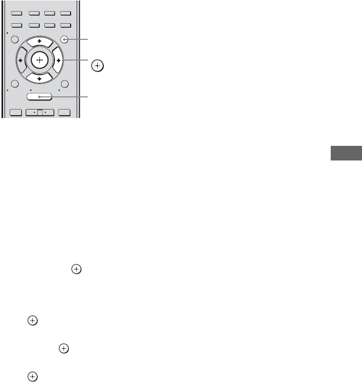
95US
“BRAVIA” Sync Features
When your TV is not compatible
with the “Control for HDMI-Easy
Setting” function
Turn the Control for HDMI function of the
receiver and the connected component on
individually.
1Perform the steps given in “When your
TV is compatible with the “Control for
HDMI-Easy Setting” function” (page
94).
2Press GUI MODE.
After “MENU ON” appears on the display
for a while, “GUI” appears and the GUI
menu appears on the TV screen.
Press MENU if the GUI menu does not
appear on the TV screen.
3Press V/v repeatedly to select
“Settings”, then press or b.
The Settings menu list appears on the TV
screen.
4Press V/v repeatedly to select “HDMI”,
then press or b.
5Press V/v repeatedly to select “Ctrl for
HDMI”, then press or b.
6Press V/v repeatedly to select “ON”,
then press .
The Control for HDMI function is set to on.
7Set the Control for HDMI function of the
connected component to on.
8Select the HDMI input (HDMI 1/2/3/4)
of the receiver and TV to match the
HDMI output of the connected
component, so that the image from the
connected component is displayed.
For details on setting the TV and connected
components, refer to the operating
instructions of the respective components.
Notes
• When you unplug the HDMI cable or change the
connection, perform the steps given in “When your
TV is compatible with the “Control for HDMI-
Easy Setting” function” (page 94) or “When your
TV is not compatible with the “Control for HDMI-
Easy Setting” function” (page 95).
• You cannot perform One-Touch Play and System
Audio Control during Control for HDMI-Easy
Setting operation.
• Before you do the Control for HDMI-Easy Setting
from the TV, be sure to turn on the TV, connected
components and receiver.
• If the playback components cannot function after
you have made the settings for Control for HDMI-
Easy Setting, check the Control for HDMI setting
on your TV.
• If the connected components do not support
Control for HDMI-Easy Setting, you need to set
the Control for HDMI function for the connected
components to on before you perform the Control
for HDMI-Easy Setting from the TV.
2CH/
A.DIRECT A.F.D. MOVIE MUSIC
RESOLUTION
.>
<
<
MENU
RETURN/
EXIT TOOLS/
OPTIONS
HOME
DISPLAY GUI MODE
O
INPUT
MODE SLEEP
NIGHT
MODE
– CATEGORY +
V/v/b,
GUI MODE
MENU

96US
Playing back components
with one-touch operation
(One-Touch Play)
You can enjoy sound and image from the
components connected to the receiver via
HDMI connections by a simple operation.
Play back a connected component.
The receiver and the TV are turned on
automatically and switched to the appropriate
HDMI input. In case the receiver or/and the
TV is in standby mode, they will be turned on
automatically.
Watching a DVD/Blu-ray disc by
simple operation
You can also select a connected component,
such as a DVD/Blu-ray disc player using the
TV menu. In this case, the receiver and the TV
switch to the appropriate HDMI input.
Note
Depending on the TV, the start of the content may
not be output.
Enjoying the TV sound
from the speakers
connected to the receiver
(System Audio Control)
You can enjoy the TV sound from the speakers
connected to the receiver by a simple
operation.
You can operate System Audio Control
function using the TV menu. For details, refer
to the operating instructions of the TV.
When System Audio Control function is
turned on, the receiver will turn on and switch
to the appropriate input automatically.
TV sound is output from the speakers
connected to the receiver, and the volume of
the TV is minimized simultaneously.
You can also use the System Audio Control
function as follows.
• If you turn on the receiver while the TV is
turned on, the System Audio Control
function will automatically be set to on and
the TV sound will output from the speakers
connected to the receiver. However, if you
turn off the receiver, the sound will output
from the TV speakers.
• You can adjust the receiver’s volume when
you adjust the TV volume.
Notes
• If System Audio Control does not function
according to your TV setting, refer to the operating
instructions of the TV.
• When “Ctrl for HDMI” is set to “ON”, the “Audio
Out” settings in the HDMI Settings menu will set
automatically depending on the System Audio
Control settings.
• When you connect a TV that does not have System
Audio Control function, the System Audio Control
function does not work.
• If the TV is turned on before turning on the
receiver, the TV sound will not be output for a
moment.
• When you switch to an input other than HDMI or
TV, the System Audio Control function will
automatically be set to off.
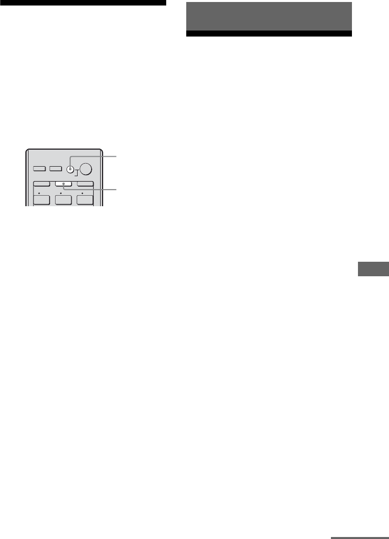
97US
S-AIR Operations
Turning off the receiver
with the TV
(System Power Off)
When you turn the TV off by using the
POWER button on the TV’s remote, the
receiver and the connected components turn
off automatically.
You can also use the receiver’s remote to turn
off the TV.
Press TV, then press AV ?/1.
The TV, receiver and the components
connected via HDMI are turned off.
Notes
• Set the TV Standby Synchro to “ON” before using
the System Power Off function. For details, refer to
the operating instructions of the TV.
• Depending on the status, the connected
components may not be turned off. For details,
refer to the operating instructions of the connected
components.
About S-AIR products
This receiver is compatible with the S-AIR
function (page 125), which allows wireless
sound transmission between S-AIR products.
When you purchase the S-AIR product, you
need to establish sound transmission (page
99).
There are two types of S-AIR product.
• S-AIR main unit (this receiver):
The S-AIR main unit is for transmitting
sound.
You can use up to 3 S-AIR main units. (The
number of usable S-AIR main unit depends
on the use environment.)
• S-AIR sub unit (not supplied): The S-AIR
sub unit is for receiving sound.
– Surround amplifier: You can enjoy
surround and surround back speakers
sound wirelessly. For details, refer to the
operating instructions supplied with the
surround amplifier.
– S-AIR receiver: You can enjoy system
sound in another room.
These S-AIR products can be purchased as an
option (the S-AIR product lineup differs
depending on the area).
Notes or instructions for the surround
amplifier or S-AIR receiver in this operating
instructions is refer only when the surround
amplifier or S-AIR receiver is used.
1 2 3
THEATER
SYSTEM STANDBY
RM SET UP
?/1
SHIFT
VIDEO 1 VIDEO 2 BD
AV
?/1
TV AMP
TV
AV ?/1
S-AIR Operations
continued
98US
Before using S-AIR products, have the
following ready.
Confirm the wireless adapters
are inserted correctly
Insert the wireless adapters firmly to the depth
into the slots of the S-AIR main unit and sub
unit respectively.
Confirm that the S-AIR IDs of
the S-AIR main unit and sub unit
are the same
The default setting of the S-AIR IDs of the
S-AIR main unit and sub unit is “A”.
Depending on the S-AIR product, you can set
the S-AIR ID by the switch or the setup menu.
For details, refer to the operating instructions
of each S-AIR product.
S-AIR products use a radio frequency of
2.4 GHz. Certain electronic equipment or
other factors may cause lost connection or
instability in S-AIR reception.
• Electronic equipment influence
The following may cause interference or
cross talk.
–Cellular phones, cordless phones
–Wireless LAN, personal computers
–Game machines using radio signals
–Microwave ovens
•Other factors
The following may cause poor reception.
–Materials or structures, such as walls and
floors
–The location where an S-AIR product is
placed
When using S-AIR products, place them as
far as possible from the above electronic
equipment, or place where S-AIR reception
is stable.
To use S-AIR products (S-AIR
main unit and sub unit)
?/1
MASTER VOLUME
SPEAKERS
PHONES 2 CH/
A.DIRECT A.F.D. MOVIE MUSIC INPUT MODE DIMMER DISPLAY
VIDEO 2 IN
VIDEO L AUDIO R
AUTO CAL MIC
MULTI CHANNEL DECODING
INPUT SELECTOR
MUTING
S-AIR sub unit
(S-AIR receiver)
S-AIR main unit
(this receiver)
S-AIR sub unit
(surround amplifier)
Room B
Room A
Insert firmly
About environments where
S-AIR products (S-AIR main unit
and sub unit) are used
99US
S-AIR Operations
Setting up an S-AIR
product
Before using an S-AIR product, be sure to
perform the following settings to establish the
sound transmission.
To make use of the S-AIR function, you need
to insert the wireless transmitter (not supplied)
into the S-AIR main unit and the wireless
transceiver (not supplied) into the S-AIR sub
unit.
Notes
• Before inserting the wireless transmitter/
transceiver, be sure to disconnect the AC power
cord (mains lead).
• Do not touch the terminals of the wireless
transmitter/transceiver.
To insert the wireless
transmitter into the S-AIR main
unit
1Remove the screws and detach the slot
cover.
Notes
• Remove the screws from the slot cover bearing the
caution mark. Do not remove other screws.
• The slot cover is no longer necessary. However,
keep it after detaching.
2Insert the wireless transmitter.
Inserting the wireless
transmitter/transceiver
VIDEO
OUT
MONITOR
L
R
DI
G
DC5V
0.7A MAX
ANTENNA
DMPORT
IN 3
AM
Y
P
B
/
C
B
COMPONENT VIDEO
OUT IN
P
R
/
C
R
IN 2 IN 1 MONITOR
OUT
SA-CD/CD/CD-R
VIDEO 1
IN
TV
AUDIO
IN
VIDEO
IN
SAT
AUDIO
OUT
AUDIO
OUT
VIDEO
OUT
OPTICAL IN
AUDIO
IN
VIDEO
IN
SUBWOOFER
AUDIO
IN
VIDEO
IN
BD
R
L
R
SAT IN
O
P
ASSIGNABLE (INPUT ONLY)
SURROU
N
FRO
N
BI-A
TV
SIRIUS
EZW-T100
EZW-T100
Slot cover
EZW-T100
Wireless transmitter
EZW-T100 slot
continued
100US
Notes
• Insert the wireless transmitter with the S-AIR logo
facing up.
• Insert the wireless transmitter so that the V marks
are aligned.
• Do not insert other than the wireless transmitter
into the EZW-T100 slot.
3Use the screws that you removed from
step 1 to fasten the wireless
transmitter.
Note
Do not use other screws to fasten the wireless
transmitter.
To insert the wireless
transceiver into the S-AIR sub
unit
For details on installing the wireless
transceiver into surround amplifier and S-AIR
receiver, refer to the operating instructions
supplied with the surround amplifier and
S-AIR receiver.
When you match the ID of the S-AIR main
unit and the S-AIR sub unit, you can establish
sound transmission. You can use multiple
S-AIR main unit by setting a different ID for
each unit.
To set the ID of the S-AIR main
unit
1Press GUI MODE.
After “MENU ON” appears on the display
for a while, “GUI” appears and the GUI
menu appears on the TV screen.
Press MENU if the GUI menu does not
appear on the TV screen.
2Press V/v repeatedly to select
“Settings”, then press or b.
The Settings menu list appears on the TV
screen.
3Press V/v repeatedly to select “S-AIR”,
then press or b.
Note
When the S-AIR transmitter (not supplied) is not
inserted into the S-AIR main unit, “S-AIR”
cannot be selected.
4Press V/v repeatedly to select “S-AIR
ID”, then press or b.
The S-AIR ID menu appears.
EZW-T100
Establishing sound transmission
between the S-AIR main unit and
S-AIR sub unit (ID setting)
2CH/
A.DIRECT A.F.D. MOVIE MUSIC
RESOLUTION
.>
<
<
MENU
RETURN/
EXIT TOOLS/
OPTIONS
HOME
DISPLAY GUI MODE
O
INPUT
MODE SLEEP
NIGHT
MODE
– CATEGORY +
GUI MODE
MENU
V/v/b,
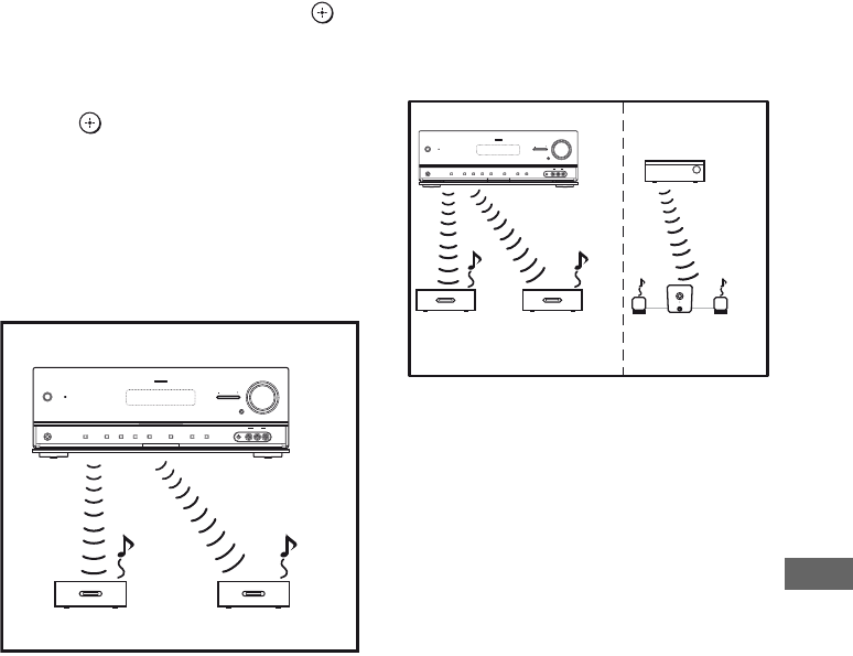
101US
S-AIR Operations
5Press V/v repeatedly to select the ID
(A, B or C) you want, then press .
The ID of the S-AIR main unit is set. “Set
S-AIR ID of the sub unit to the same as that
of the main unit” appears.
6Press to set the ID of the S-AIR sub
unit.
7Press GUI MODE.
The GUI menu turns off.
8Set the S-AIR sub unit to the same ID.
Sound transmission is established as
follows (example):
Tip
To confirm the current ID, performs steps 1 to 3
above. When you pair the S-AIR main unit with
the S-AIR sub unit (page 102), “(Pairing)”
appears beside the ID on the TV screen in the
GUI menu.
To exit the menu
Press MENU.
To set the ID of the S-AIR sub
unit
Be sure to match the ID on S-AIR sub unit you
want to the S-AIR main unit.
For details on setting the ID of the surround
amplifier and S-AIR receiver, refer to the
operating instructions supplied with the
surround amplifier and S-AIR receiver.
To use multiple S-AIR main
units
You can use multiple S-AIR main units by
setting a different ID for each component.
Notes
• Sources with copyright protection may not be
playable on S-AIR sub unit.
• When sound transmission is established
– sound can only be output from the S-AIR
receiver if you connect the components to this
receiver via the analog jacks. The sound cannot
be output if the components are connected to the
COAXIAL, OPTICAL or HDMI jacks on this
receiver.
– the headphones function on the surround
amplifier is not available.
ID A
ID A
ID A
?/1
MASTER VOLUME
SPEAKERS
PHONES 2 CH/
A.DIRECT A.F.D. MOVIE MUSIC INPUT MODE DIMMER DISPLAY
VIDEO 2 IN
VIDEO L AUDIO R
AUTO CAL MIC
MULTI CHANNEL DECODING
INPUT SELECTOR
MUTING
S-AIR main unit
S-AIR sub unit S-AIR sub unit
ID A ID A ID B
ID A ID B
?/1
MASTER VOLUME
SPEAKERS
PHONES 2 CH/
A.DIRECT A.F.D. MOVIE MUSIC INPUT MODE DIMMER DISPLAY
VIDEO 2 IN
VIDEO L AUDIO R
AUTO CAL MIC
MULTI CHANNEL DECODING
INPUT SELECTOR
MUTING
S-AIR main unit Other S-AIR main
unit
S-AIR sub
unit
S-AIR sub
unit
S-AIR sub unit
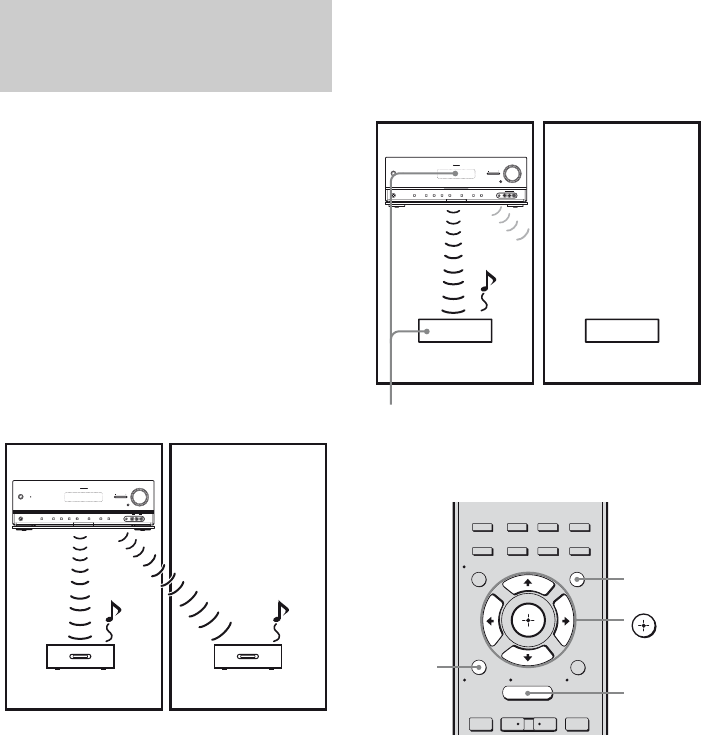
102US
To establish sound transmission, you need to
set the same ID for your S-AIR main unit and
S-AIR sub unit.
However, if your neighbors have S-AIR
products and their IDs are the same as yours,
your neighbors could receive the sound of
your S-AIR main unit or vice versa.
To prevent this, you can pair the S-AIR main
unit with a specific S-AIR sub unit by
performing the pairing operation.
xBefore pairing
Sound transmission is established by the ID
(example).
xAfter pairing
Sound transmission is established between the
paired S-AIR main unit and S-AIR sub unit(s)
only.
To perform pairing
1Place the S-AIR sub unit that
you want to pair near the S-AIR
main unit.
2Match the IDs of the S-AIR main
unit and the S-AIR sub unit.
• To set the ID of the S-AIR main unit,
see “To set the ID of the S-AIR main
unit” (page 100).
• To set the ID of the S-AIR sub unit,
refer to the operating instructions
supplied with the S-AIR sub unit.
Pairing the S-AIR main unit with
a specific S-AIR sub unit
(Pairing operation)
ID A
ID A
ID A
?/1
MASTER VOLUME
SPEAKERS
PHONES 2 CH/
A.DIRECT A.F.D. MOVIE MUSIC INPUT MODE DIMMER DISPLAY
VIDEO 2 IN
VIDEO L AUDIO R
AUTO CAL MIC
MULTI CHANNEL DECODING
INPUT SELECTOR
MUTING
Your room
S-AIR main unit
S-AIR sub unit S-AIR sub unit
Neighbor
ID A ID A
?/1
MASTER VOLUME
SPEAKERS
PHONES 2 CH/
A.DIRECT A.F.D. MOVIE MUSIC INPUT MODE DIMMER DISPLAY
VIDEO 2 IN
VIDEO L AUDIO R
AUTO CAL MIC
MULTI CHANNEL DECODING
INPUT SELECTOR
MUTING
Your room
S-AIR main unit
S-AIR sub unit S-AIR sub unit
Neighbor
No transmission
Pairing
2CH/
A.DIRECT A.F.D. MOVIE MUSIC
RESOLUTION
.>
<
<
MENU
RETURN/
EXIT TOOLS/
OPTIONS
HOME
DISPLAY GUI MODE
O
INPUT
MODE SLEEP
NIGHT
MODE
– CATEGORY +
V/v/B/b,
GUI MODE
MENU
RETURN/
EXIT O

103US
S-AIR Operations
3Press GUI MODE.
After “MENU ON” appears on the
display for a while, “GUI” appears and
the GUI menu appears on the TV screen.
Press MENU if the GUI menu does not
appear on the TV screen.
4Press V/v repeatedly to select
“Settings”, then press or b.
The Settings menu list appears on the TV
screen.
5Press V/v repeatedly to select
“S-AIR”, then press .
The S-AIR menu appears.
Note
When the S-AIR transmitter (not supplied) is
not inserted into the S-AIR main unit, “S-AIR”
cannot be selected.
6Press V/v repeatedly to select
“Pairing”, then press .
“Put the S-AIR sub unit near the S-AIR
main unit. Turn on power and start
pairing.” appears on the TV screen. The
S-AIR main unit is ready to start pairing.
7Press B/b repeatedly to select
“Yes”, then press .
The S-AIR main unit starts pairing.
“Pairing. Do the pairing operation with
the S-AIR sub unit.” appears.
8Start pairing of the S-AIR sub
unit.
Refer to the operating instructions of the
S-AIR sub unit.
Notes
• Perform pairing within 5 minutes in step 6. If
you do not, pairing is recognized as failed,
and the screen changes accordingly. In this
case, see “If pairing fails” (page 103).
• When sound transmission is established,
“Pairing complete. To perform pairing to
another S-AIR sub unit, select “Continue”.”
appears.
9Press B/b repeatedly to select
“Finish” or “Continue”, then
press .
• “Finish”: Finishes pairing.
• “Continue”: Continues to perform
pairing to another S-AIR sub unit.
Tip
You can confirm the pairing completion or the
current ID by checking the “S-AIR Settings”
screen. “(PAIRING)” appears beside the
current S-AIR ID.
10Press GUI MODE.
The GUI menu turns off.
Note
After you have performed pairing, if you select
the “S-AIR ID” menu, the ID setting (“A", “B”
or “C”) that you last used is displayed.
If pairing fails
“Pairing failed. Retry?” appears.
To perform pairing again, select “Yes”.
To finish pairing, select “No”.
To quit pairing during setting
Press RETURN/EXIT O.
To cancel pairing
Perform the ID setting of the main unit
according to the procedure of “To set the ID of
the S-AIR main unit” (page 100). If you reset
the ID (even the same ID again), pairing is
canceled.
104US
Enjoying the system’s
sound in another room
(For the S-AIR receiver only (not
supplied))
You can enjoy the system’s sound in another
room by using the S-AIR receiver. The S-AIR
receiver can be placed in another room for
enjoying the system’s sound there.
For details of the S-AIR receiver, refer to the
operating instructions supplied with the S-AIR
receiver.
1Set the ID of the S-AIR receiver
to match the ID of the S-AIR
main unit.
• To set the ID of the S-AIR main unit,
see “To set the ID of the S-AIR main
unit” (page 100).
• To set the ID of the S-AIR receiver,
refer to the operating instructions
supplied with the S-AIR receiver.
Notes
• When you are using another S-AIR sub unit,
such as a surround amplifier, do not change
the ID of the S-AIR main unit. Set the ID of
the S-AIR receiver to match the ID of the
S-AIR main unit.
• When you pair the S-AIR main unit and
another S-AIR sub unit, such as a surround
amplifier, you also need to pair the S-AIR
main unit and the S-AIR receiver. For details,
see “Pairing the S-AIR main unit with a
specific S-AIR sub unit (Pairing operation)”
(page 102).
2Press GUI MODE.
After “MENU ON” appears on the
display for a while, “GUI” appears and
the GUI menu appears on the TV screen.
Press MENU if the GUI menu does not
appear on the TV screen.
3Press V/v repeatedly to select
“Settings”, then press or b.
The Settings menu list appears on the TV
screen.
4Press V/v repeatedly to select
“S-AIR”, then press or b.
Note
When the S-AIR transmitter (not supplied) is
not inserted into the S-AIR main unit, “S-AIR”
cannot be selected.
5Press V/v repeatedly to select
“S-AIR Mode”, then press .
6Press V/v repeatedly to select
the setting you want.
• Party: The S-AIR receiver outputs
sound according to the input selected on
the S-AIR main unit. However, if DVD
is selected on S-AIR main unit, S-AIR
receiver remains as the last selected
input.
• Separate: You can select the input you
want for the S-AIR receiver while the
input of the S-AIR main unit remain
unchanged.
7Press GUI MODE.
The GUI menu turns off.
2CH/
A.DIRECT A.F.D. MOVIE MUSIC
RESOLUTION
.>
<
<
MENU
RETURN/
EXIT TOOLS/
OPTIONS
HOME
DISPLAY GUI MODE
O
INPUT
MODE SLEEP
NIGHT
MODE
– CATEGORY +
GUI MODE
MENU
V/v/b,
105US
S-AIR Operations
8Select the desired function on
the S-AIR receiver.
xWhen “Party” is set
The S-AIR receiver’s function changes
sequentially as you press INPUT
SELECTOR +/– on the receiver or S-AIR
CH of the S-AIR receiver.
xWhen “Separate” is set
The S-AIR receiver’s function changes
by pressing S-AIR CH of the S-AIR
receiver.
Note
When TUNER (FM/AM band) is selected on
the S-AIR main unit, you can only select the
same band for the tuner on the S-AIR receiver.
However, you can select input other than
TUNER on the S-AIR receiver.
9Adjust the volume on the S-AIR
receiver.
Note
The sound of the S-AIR receiver may be cut off by
operation of the S-AIR main unit.
To control the system from the
S-AIR receiver
You can control the system from the S-AIR
receiver by using the following buttons.
For details, refer to the operating instructions
of the S-AIR receiver.
Changing the channel
for better sound
transmission
If you use multiple wireless systems which
sharing the 2.4 GHz band, such as wireless
LAN or Bluetooth, the transmission of S-AIR
products or other wireless systems may be
unstable. In this case, transmission may be
improved by changing the “RF Change”
setting.
1Press GUI MODE.
After “MENU ON” appears on the
display for a while, “GUI” appears and
the GUI menu appears on the TV screen.
Press MENU if the GUI menu does not
appear on the TV screen.
2Press V/v repeatedly to select
“Settings”, then press or b.
The Settings menu list appears on the TV
screen.
3Press V/v repeatedly to select
“S-AIR”, then press .
The S-AIR menu appears.
Note
When the S-AIR transmitter (not supplied) is
not inserted into the S-AIR main unit, “S-AIR”
cannot be selected.
Press Operation
N, X, x,
./>
Share the same operations on the
remote
S-AIR CH Change the function of the
S-AIR main unit
2CH/
A.DIRECT A.F.D. MOVIE MUSIC
RESOLUTION
.>
<
<
MENU
RETURN/
EXIT TOOLS/
OPTIONS
HOME
DISPLAY GUI MODE
O
INPUT
MODE SLEEP
NIGHT
MODE
– CATEGORY +
GUI MODE
MENU
V/v/b,
continued
106US
4Press V/v repeatedly to select
“RF Change”, then press or
b.
5Press V/v repeatedly to select
the setting you want.
• AUTO: Normally select this. The
system changes “RF Change” to “ON”
or “OFF” automatically.
• ON: The system transmits sound by
searching for a better channel for
transmitting.
• OFF: The system transmits sound by
fixing the channel for transmitting.
6Press GUI MODE.
The GUI menu turns off.
7When you set “RF Change” to
“OFF”, select the ID so that
sound transmission is most
stable.
Notes
• When the wireless transmitter is not inserted in the
S-AIR main unit, you cannot set “RF Change”.
• In most cases, you will not need to change this
setting.
– If “RF Change” is set to “OFF”, transmission
between the S-AIR main unit and S-AIR sub unit
can be performed using one of the following
channels.
– S-AIR ID A: equivalent channel for IEEE
802.11b/g channel 1
– S-AIR ID B: equivalent channel for IEEE
802.11b/g channel 6
– S-AIR ID C: equivalent channel for IEEE
802.11b/g channel 11
• The transmission may be improved by changing
the transmission channel (frequency) of the other
wireless system(s). For details, refer to the
operating instructions of the other wireless
system(s).
Stabilizing S-AIR
reception
Read the following when S-AIR reception is
poor or unstable.
Check the following.
• Keep cords that are connected to the S-AIR
product (AC power cord (mains lead),
speaker cords, or other cords) away from the
wireless adapter and slot.
• Keep as much space as possible around
S-AIR products.
–Avoid placing S-AIR products on top of or
directly below other electronic equipment.
–Avoid placing S-AIR products in a closed
rack, metal rack or under a table.
When S-AIR reception is poor
107US
S-AIR Operations
• Adjust the location (height, orientation, and
place in the room) of S-AIR products until
reception is the most stable.
– Place so that the wireless adapters of the
S-AIR main unit and sub unit are closer.
– Place so that S-AIR products are separated
from other wireless devices.
– Place so that S-AIR products are separated
from metal doors or tables.
If you still cannot improve S-AIR reception,
change the “RF Change” setting (page 105).
Enjoying the S-AIR
receiver while the S-AIR
main unit is in standby
mode
(For the S-AIR receiver only (not
supplied))
You can enjoy the S-AIR receiver while the
S-AIR main unit is in standby mode by setting
“S-AIR Stby” to “ON”.
1Press GUI MODE.
After “MENU ON” appears on the
display for a while, “GUI” appears and
the GUI menu appears on the TV screen.
Press MENU if the GUI menu does not
appear on the TV screen.
2Press V/v repeatedly to select
“Settings”, then press or b.
The Settings menu list appears on the TV
screen.
3Press V/v repeatedly to select
“S-AIR”, then press .
The S-AIR menu appears.
Note
When the S-AIR transmitter (not supplied) is
not inserted into the S-AIR main unit, “S-AIR”
cannot be selected.
4Press V/v repeatedly to select
“S-AIR Stby”, then press .
?/1
MASTER VOLUME
SPEAKERS
PHONES 2 CH/
A.DIRECT A.F.D. MOVIE MUSIC INPUT MODE DIMMER DISPLAY
VIDEO 2 IN
VIDEO L AUDIO R
AUTO CAL MIC
MULTI CHANNEL DECODING
INPUT SELECTOR
MUTING
?/1
MASTER VOLUME
SPEAKERS
PHONES 2 CH/
A.DIRECT A.F.D. MOVIE MUSIC INPUT MODE DIMMER DISPLAY
VIDEO 2 IN
VIDEO L AUDIO R
AUTO CAL MIC
MULTI CHANNEL DECODING
INPUT SELECTOR
MUTING
2CH/
A.DIRECT A.F.D. MOVIE MUSIC
RESOLUTION
.>
<
<
MENU
RETURN/
EXIT TOOLS/
OPTIONS
HOME
DISPLAY GUI MODE
O
INPUT
MODE SLEEP
NIGHT
MODE
– CATEGORY +
GUI MODE
MENU
V/v/b,
continued

108US
5Press V/v repeatedly to select
the setting you want.
• ON: You can enjoy the S-AIR receiver
while the S-AIR main unit is in standby
mode or turned on.
• OFF: You cannot enjoy the S-AIR
receiver while the S-AIR main unit is in
standby mode.
To exit the menu
Press MENU.
Notes
• When you set “S-AIR Stby” to “ON”, the power
consumption increases during the standby mode.
• When the wireless transmitter is not inserted in the
S-AIR main unit, you cannot set “S-AIR Stby”.
• When the wireless transmitter is removed from the
S-AIR main unit, “S-AIR Stby” is set to “OFF”
automatically.
• If you have selected TUNER (FM/AM band) on
the S-AIR main unit before you turn it off and
“S-AIR Stby” is set to “ON”, you can only select
the same band for the tuner on the S-AIR receiver.
However, you can select input other than TUNER
on the S-AIR receiver.
• The sound of the S-AIR receiver may be cut off by
operation of the S-AIR main unit.
Switching between
digital and analog audio
(INPUT MODE)
When you connect components to both digital
and analog audio input jacks on the receiver,
you can fix the audio input mode to either of
them, or switch from one to the other,
depending on the type of material you intend
to watch.
1Press the input button.
You can also use the INPUT SELECTOR
+/– on the receiver.
2Press INPUT MODE repeatedly
to select the audio input mode.
The selected audio input mode appears on
the display.
Audio input modes
xAUTO
Gives priority to digital audio signals when
there are both digital and analog connections.
If there are no digital audio signals, analog
audio signals are selected.
xANALOG
Specifies the analog audio signals input to the
AUDIO IN (L/R) jacks.
Notes
• Some audio input modes may not be set up
depending on the input.
• When either HDMI input (HDMI 1/2/3/4), SIRIUS
or DMPORT input is selected, “------” appears on
the display, and you cannot select other modes.
Select an input mode other than the HDMI input
(HDMI 1/2/3/4), SIRIUS and DMPORT input,
then set the audio input mode.
• When “Analog Direct” is being used, audio input is
automatically set to “ANALOG”. You cannot
select other modes.
Other Operations
109US
Other Operations
Enjoying the sound/
images from other inputs
You can reassign video and/or audio signals to
another input.
For example, connect the OPTICAL OUT jack
of the DVD player to the OPTICAL BD IN
jack of this receiver when you want to input
the digital optical audio signals from the DVD
player.
Connect the component video jack of the DVD
player to the COMPONENT VIDEO IN 1 jack
of this receiver when you want to input the
video signals from the DVD player.
Assign video and/or audio signals to the DVD
input jack using “Input Assign” in the Input
Option menu.
1Press GUI MODE.
After “MENU ON” appears on the
display for a while, “GUI” appears and
the GUI menu appears on the TV screen.
Press MENU if the GUI menu does not
appear on the TV screen.
2Press V/v repeatedly to select
“Input”, then press or b.
3Press V/v repeatedly to select
the input name you want to
assign.
4Press TOOLS/OPTIONS.
5Press V/v repeatedly to select
“Input Assign”, then press
or b.
6Select the audio and/or video
signals you want to assign to
the input which you selected in
step 3 using V/v/B/b.
7Press RETURN/EXIT O to
enter the setting.
Input
VIDEO 1
VIDEO 2
DVD
SAT
BD
Input
VIDEO 1
VIDEO 2
DVD
SAT
BD Name lnput
Input Assign
Select Video Select Audio
COMP.2
COMP.3
BD OPT
DVD COAX
ANALOG
Input Assign
RETURN
COMP.1
continued

110US
* Initial setting
Notes
• You cannot assign optical signals from an input
source to the optical input jacks on the receiver,
and you cannot assign coaxial signals from the
input source to the coaxial input jacks on the
receiver.
• When you assign the digital audio input, the
INPUT MODE setting may change automatically.
• You cannot reassign more than one HDMI input to
the same input.
• You cannot reassign more than one digital audio
input to the same input.
• You cannot reassign more than one component
video input to the same input.
Input name
VIDEO1 VIDEO2 BD DVD SAT SA-CD/
CD/
CD-R
HDMI1 HDMI2 HDMI3 HDMI4
Assignable
video input
jacks
COMP.1 aaa*aa a
COMP.2 aaaa*aa
COMP.3 a a aaa*a
CVBS a*a*a–a–––––
HDMI1 a a aaa a a*– – –
HDMI2 a a aaa a –a*– –
HDMI3 a a aaa a ––a*–
HDMI4 a a aaa a –––a*
NONE a a aaa a*– – – –
Assignable
audio input
jacks
BD OPT aaa*a–a––––
SAT OPT aa–aa*a––––
DVD COAX aaaa*aa ––––
ANALOG a*a*a–aa*– – – –

111US
Other Operations
Using the Sleep Timer
You can set the receiver to turn off
automatically at a specified time.
Press SLEEP repeatedly while the
power is on.
Each time you press the button, the display
changes cyclically as follows:
0:30:00 t 1:00:00 t 1:30:00 t 2:00:00
t OFF
When Sleep Timer is activated, “SLEEP”
lights up in the display.
Tip
To check the remaining time before the receiver
turns off, press SLEEP. The remaining time appears
on the display. If you press SLEEP again, the Sleep
Timer will be canceled.
Changing the brightness
of the front panel display
(DIMMER)
You can change the brightness of the front
panel display.
1Press AMP.
2Press MENU.
3Press V/v repeatedly to select
“SYSTEM”, then press or b.
4Press V/v repeatedly to select
“DIMMER”, then press or b.
5Press V/v repeatedly to select
the setting you want, then
press .
The front panel display will change the
brightness according to the setting you
have selected.
Tip
You can also press DIMMER repeatedly on the
receiver to change the brightness of the front panel
display.

112US
Enjoying the surround
effect at low volume
levels
(NIGHT MODE)
This function allows you to retain a theater like
environment at low volume levels. This
function can be used with other sound fields.
When watching a movie late at night, you will
be able to hear the dialog clearly even at a low
volume level.
Press NIGHT MODE.
The NIGHT MODE function is activated. The
NIGHT MODE is set to on and off as you
press NIGHT MODE.
Note
This function does not work in the following cases.
– PCM signals with a sampling frequency of more
than 96 kHz are being received.
– Dolby TrueHD signals with a sampling frequency
of more than 96 kHz are being received.
Tip
While this function is on, the Bass, Treble, and
Effect Levels increase, and “D.Range Comp” is
automatically set to “MAX”.
Recording using the
receiver
You can record from a video/audio component
using the receiver. Refer to the operating
instructions supplied with your recording
component.
You can record onto a CD-R using the
receiver. Refer to the operating instructions
supplied with your CD recorder.
1Press one of the input buttons
to select the playback
component.
You can also use INPUT SELECTOR +/–
on the receiver.
2Prepare the playback
component for playing.
For example, tune to the radio station you
want to record (page 52).
3Prepare the recording
component.
Insert a blank CD-R into the CD recorder
and adjust the recording level.
4Start recording on the
recording component, then
start playback on the playback
component.
Note
Sound adjustments do not affect the signal output
from the SA-CD/CD/CD-R OUT jacks.
2CH/
A.DIRECT A.F.D. MOVIE MUSIC
RESOLUTION
DISPLAY GUI MODE
INPUT
MODE SLEEP
NIGHT
MODE
NIGHT
MODE
Recording onto a CD-R
113US
Other Operations
1Press the input button of the
playback component.
You can also use INPUT SELECTOR
+/– on the receiver.
2Prepare the playback
component for playing.
For example, insert the video tape you
want to copy into the VCR.
3Prepare the recording
component.
Insert a blank video tape, etc. into the
recording component (connected to
VIDEO 1 OUT jack) for recording.
4Start recording on the
recording component, then
start playback on the playback
component.
Notes
• Some sources contain copy guards to prevent
recording. In this case, you may not be able to
record from the source.
• Only analog input signals are output from the
analog output jack (for recording).
• HDMI sound cannot be recorded.
Using a bi-amplifier
connection
If you are not using surround back speakers,
you can connect the front speakers to the
SPEAKERS SURROUND BACK/BI-AMP/
FRONT B terminals using a bi-amplifier
connection.
To connect speakers
Connect the jacks on the Lo (or Hi) side of the
front speakers to the SPEAKERS FRONT A
terminals, and connect the jacks on the Hi (or
Lo) side of the front speakers to the
SPEAKERS SURROUND BACK/FRONT B/
BI-AMP terminals.
Make sure that metal fittings of Hi/Lo attached
to the speakers have been removed from the
speakers. Not doing so may cause a
malfunction of the receiver.
Recording onto a recording
media
VIDEO
OUT
MONITOR
L
R
DIGITAL
(ASSIGNABLE)
DC5V
0.7A MAX
HDMI
ANTENNA
DMPORT
IN 4
ASSIGNABLE (INPUT ONLY)
IN 3
IN 2
IN 3 IN 1 OUT
AM
Y
P
B
/
C
B
COMPONENT VIDEO
OUT IN
P
R
/
C
R
IN 2 IN 1 MONITOR
OUT
SA-CD/CD/CD-R
VIDEO 1
IN
TV
AUDIO
IN
VIDEO
IN
SAT
AUDIO
OUT
AUDIO
OUT
VIDEO
OUT
OPTICAL IN
AUDIO
IN
VIDEO
IN
SUBWOOFER
AUDIO
IN
VIDEO
IN
BD
L
R
SAT IN BD IN DVD IN
OPTICAL COAXIAL
ASSIGNABLE (INPUT ONLY)
TV
SIRIUS
LRLR
SPEAKERS
CENTER
FRONT A
SURROUND BACK/
FRONT B/
BI-AMP
LR
SURROUND
LRLR
CENTER
FRONT A
SURROUND BACK/
FRONT B/
BI-AMP
LR
SURROUND
(for AUDIO)
EZW-T100
Hi
Lo
Hi
Lo
SPEAKERS
Front speaker
(R)
Front speaker
(L)
continued
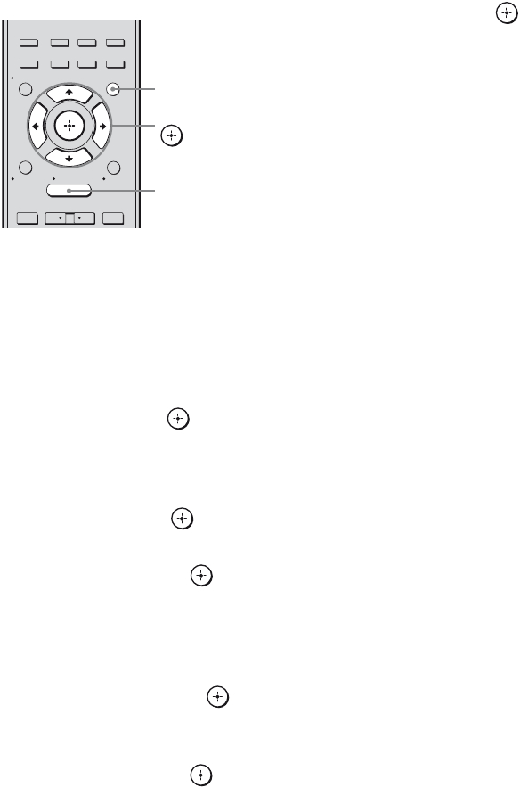
114US
To set up speakers
1Press GUI MODE.
After “MENU ON” appears on the
display for a while, “GUI” appears and
the GUI menu appears on the TV screen.
Press MENU if the GUI menu does not
appear on the TV screen.
2Press V/v repeatedly to select
“Settings” then press or b.
The Settings menu list appears on the TV
screen.
3Press V/v repeatedly to select
“Speaker”, then press or b.
4Press V/v repeatedly to select
“SP Pattern”, then press or
b.
5Press V/v repeatedly to select
the appropriate speaker pattern
so that there are no surround
back speakers, then press
or b.
6Press V/v repeatedly to select
“SB Assign”, then press or
b.
7Press V/v repeatedly to select
“BI-AMP”, then press or b.
The same signals output from the
SPEAKERS FRONT A terminals can be
output from the SPEAKERS
SURROUND BACK/FRONT B/
BI-AMP terminals.
To exit the menu
Press MENU.
Notes
• Set “SB Assign” to “BI-AMP” before you perform
Auto Calibration.
• If you set “SB Assign” to “BI-AMP”, the speaker
level and distance settings of the surround back
speakers become invalid, and those of the front
speakers are used.
• If you set “SP Pattern” to a setting with surround
back speakers, you cannot set “SB Assign” to
“BI-AMP”.
2CH/
A.DIRECT A.F.D. MOVIE MUSIC
RESOLUTION
.>
<
<
MENU
RETURN/
EXIT TOOLS/
OPTIONS
HOME
DISPLAY GUI MODE
O
INPUT
MODE SLEEP
NIGHT
MODE
– CATEGORY +
V/v/B/b,
GUI MODE
MENU

115US
Using the Remote
Operating each
component using the
remote
You can control Sony or non-Sony
components you are using with the remote
supplied with the receiver.
The remote is initially set to control Sony
components.
When you change the settings of the remote
according to the components you are using,
you can control non-Sony and other Sony
components that the remote is initially unable
to control (page 117).
1Press the input button that
matches the connected
component that you want to
operate.
2Press the appropriated buttons
to use the function listed in the
table below.
Note
You may not be able to operate some functions for
the components you are using.
Using the Remote
Operating the components
connected to the receiver
continued

116US
Table of buttons used to control each component
*1 LD player only.
*2 Deck B only.
*3 Video CD only.
Component
Button
TV VCR DVD
player,
DVD/VHS
combo
Blu-ray
Disc
Player
HDD
Recorder
PSX Video CD
player, LD
player
Digital
CATV
terminal
DSS Tape deck
A/B
DAT
deck
CD
player,
MD deck
DIGITAL
MEDIA
PORT
device
AV ?/1zz z z z z z z z z z
Numeric buttons zz z z z z z z z z z z z
TV INPUT, WIDE z
-/--, >10, CLEAR zz z z z z z z z z z
ENT/MEM zz z z z z z
*1 zzz z z
TOOLS/OPTIONS zzzzz zz
DISPLAY zz z z z z z z z z
RETURN/EXIT Ozzzzzzzz z
V/v/B/b, ,
MENU, HOME
zz z z z z z z z
./>zz z z z z z z z
*2 zz z
/zzzzz z z
m/TUNING –,
M/TUNING +
zz z z z z z z z z z z
DISC SKIP zz z
*3 z
N, X, xzz z z z z z z z z z z
MUTING,
MASTER VOL +/–,
TV VOL +/–
z
PRESET +/–,
TV CH +/–
zz z z z z
*1 zz
BD/DVD TOP MENU,
BD/DVD MENU
zz z
F1, F2 zz
<
<

117US
Using the Remote
Programming the remote
You can customize the remote to match the
components connected to your receiver. You
can even program the remote to control non-
Sony components and also Sony components
that the remote is normally unable to control.
The procedure below uses as an example a
case in which a VCR made by a company
other than Sony is connected to the VIDEO 1
IN jacks on the receiver.
Before you begin, note that:
– You cannot change the settings of TUNER
and DMPORT.
– The remote can control only components
that accept infrared wireless control signals.
Be sure to turn on the receiver and
point the remote towards the
receiver when performing the
following procedure.
1Press and hold RM SET UP,
then press AV ?/1.
The RM SET UP indicator slowly flashes.
2Press the input button
(including TV) for the
component you want to control.
For example, if you are going to control a
VCR connected to VIDEO 1 IN, press
VIDEO 1.
The RM SET UP and SHIFT indicator
light up.
If you press the button for a component of
which you cannot program the remote,
such as DMPORT, etc., the RM SET UP
indicator keeps flashing.
3Press numeric buttons to enter
the numeric code (or one of the
codes if more than one code
exists) corresponding to the
component and the maker of
the component you want to
control.
See the tables on page 118–121 for
information on the numeric code(s).
Note
For a TV remote code value, only numbers in
the 500’s are valid.
4Press ENT/MEM.
Once the numeric code has been verified,
the RM SET UP indicator slowly flashes
twice and the remote automatically exits
the programming mode.
5Repeat steps 1 to 4 to control
other components.
Notes
• The indicator turns off while a valid button is
pressed.
• In step 2, if you press TUNER, you can only
program the button to control a tuner (page 118).
• In step 2, if you want to change to other input, press
SHIFT and then press the new input button you
want.
• For the numeric codes, only the last three numbers
entered are valid.
To cancel programming
Press RM SET UP during any step. The RM
SET UP indicator flashes 5 times in quick
succession. The remote automatically exits the
programming mode.
To activate the input after
programming
Press the programmed button to activate the
input you want.
continued

118US
If programming is
unsuccessful, check the
following:
• If the indicator does not light up in step 1, the
batteries are weak. Replace both batteries.
• If the indicator flashes 5 times in quick
succession while entering the numeric code,
an error has occurred. Start again from step
1.
Use the numeric codes in the tables below to
control non-Sony components and also Sony
components that the remote is normally unable
to control. Since the remote signal that a
component accepts differs depending on the
model and year of the component, more than
one numeric code may be assigned to a
component. If you fail to program your remote
using one of the codes, try using other codes.
Notes
• The numeric codes are based on the latest
information available for each brand. There is a
chance, however, that your component will not
respond to some or all of the codes.
• All of the input buttons on this remote may not be
available when used with your particular
component.
To control a tuner
To control a CD player
To control a DAT deck
To control a tape deck
The numeric codes
corresponding to the component
and the maker of the component
Maker Code(s)
SONY 002, 005
Maker Code(s)
SONY 101, 102, 103
DENON 104, 123
JVC 105, 106, 107
KENWOOD 108, 109, 110
MAGNAVOX 111, 116
MARANTZ 116
ONKYO 112, 113, 114
PANASONIC 115
PHILIPS 116
PIONEER 117
TECHNICS 115, 118, 119
YAMAHA 120, 121, 122
Maker Code(s)
SONY 203
PIONEER 219
Maker Code(s)
SONY 201, 202
DENON 204, 205
KENWOOD 206, 207, 208, 209
NAKAMICHI 210
PANASONIC 216
PHILIPS 211, 212
PIONEER 213, 214
TECHNICS 215, 216
YAMAHA 217, 218

119US
Using the Remote
To control an MD deck
To control an HDD recorder
To control a Blu-ray disc player/
recorder
To control a PSX
To control a DVD player
To control a DVD recorder
To control a DVD/VHS COMBO
To control a DVD/HDD COMBO
To control a TV
Maker Code(s)
SONY 301
DENON 302
JVC 303
KENWOOD 304
Maker Code(s)
SONY 307, 308, 309
Maker Code(s)
SONY 310, 311, 312
Maker Code(s)
SONY 313, 314, 315
Maker Code(s)
SONY 401, 402, 403
BROKSONIC 424
DENON 405
HITACHI 416
JVC 415, 423
MITSUBISHI 419
ORITRON 417
PANASONIC 406, 408, 425
PHILIPS 407
PIONEER 409, 410
RCA 414
SAMSUNG 416, 422
TOSHIBA 404, 421
ZENITH 418, 420
Maker Code(s)
SONY 401, 402, 403
Maker Code(s)
SONY 411
Maker Code(s)
SONY 401, 402, 403
Maker Code(s)
SONY 501, 502
AIWA 501, 536, 539
AKAI 503
AOC 503
CENTURION 566
CORONADO 517
CURTIS-MATHES 503, 551, 566, 567
DAYTRON 517, 566
DAEWOO 504, 505, 506, 507,
515, 544
FISHER 508, 545
FUNAI 548
FUJITSU 528
GOLDSTAR/LG 503, 512, 515, 517,
534, 544, 556, 568
GRUNDIG 511, 533, 534
HITACHI 503, 513, 514, 515,
517, 519, 544, 557,
571
ITT/NOKIA 521, 522
J.C.PENNY 503, 510, 566
JVC 516, 552
KMC 517
MAGNAVOX 503, 515, 517, 518,
544, 566
MARANTZ 527
MITSUBISHI/MGA 503, 519, 527, 544,
566, 568
NEC 503, 517, 520, 540,
544, 554, 566
NORDMENDE 530, 558
NOKIA 521, 522, 573, 575
PANASONIC 509, 524, 553, 559,
572
continued

120US
To control an LD player
To control a video CD player
To control a VCR
* If an AIWA VCR does not work even though you
enter the code for AIWA, enter the code for Sony
instead.
PHILIPS 515, 518, 557, 570,
571
PHILCO 503, 504, 514, 517,
518
PIONEER 509, 525, 526, 540,
551, 555
PORTLAND 503
QUASAR 509, 535
RADIO SHACK 503, 510, 527, 565,
567
RCA/PROSCAN 503, 510, 523, 529,
544
SAMSUNG 503, 515, 517, 531,
532, 534, 544, 556,
557, 562, 563, 566,
569
SAMPO 566
SABA 530, 537, 547, 549,
558
SANYO 508, 545, 546, 560,
567
SCOTT 503, 566
SEARS 503, 508, 510, 517,
518, 551
SHARP 517, 535, 550, 561,
565
SYLVANIA 503, 518, 566
THOMSON 530, 537, 547, 549
TOSHIBA 535, 539, 540, 541,
551
TELEFUNKEN 530, 537, 538, 547,
549, 558
TEKNIKA 517, 518, 567
WARDS 503, 517, 566
YORK 566
ZENITH 542, 543, 567
GE 503, 509, 510, 544
LOEWE 515, 534, 556
Maker Code(s)
SONY 601, 602, 603
PIONEER 606
Maker Code(s)
Maker Code(s)
SONY 605
Maker Code(s)
SONY 701, 702, 703, 704,
705, 706
AIWA* 710, 750, 757, 758
AKAI 707, 708, 709, 759
BLAUPUNKT 740
EMERSON 711, 712, 713, 714,
715, 716, 750
FISHER 717, 718, 719, 720
GENERAL ELECTRIC
(GE)
721, 722, 730
GOLDSTAR/LG 723, 753
GRUNDIG 724
HITACHI 722, 725, 729, 741
ITT/NOKIA 717
JVC 726, 727, 728, 736
MAGNAVOX 730, 731, 738
MITSUBISHI/MGA 732, 733, 734, 735
NEC 736
PANASONIC 729, 730, 737, 738,
739, 740
PHILIPS 729, 730, 731
PIONEER 729
RCA/PROSCAN 722, 729, 730, 731,
741, 747
SAMSUNG 742, 743, 744, 745
SANYO 717, 720, 746
SHARP 748, 749
TELEFUNKEN 751, 752
TOSHIBA 747, 756
ZENITH 754

121US
Using the Remote
To control a satellite tuner
To control a cable box
Clearing all the contents
of the remote’s memory
1While holding down MASTER
VOL – , press and hold ?/1, then
press AV ?/1.
The RM SET UP indicator flashes 3
times.
2Release all buttons.
All the contents of the remote’s memory
(i.e., all the programmed data) are
cleared.
Maker Code(s)
SONY 801, 802, 803, 804,
824, 825, 865
AMSTRAD 845, 846
BskyB 862
GENERAL ELECTRIC
(GE)
866
GRUNDIG 859, 860
HUMAX 846, 847
THOMSON 857, 861, 864, 876
PACE 848, 849, 850, 852,
862, 863, 864
PANASONIC 818, 855
PHILIPS 856, 857, 858, 859,
860, 864, 874
NOKIA 851, 853, 854, 864
RCA/PROSCAN 866, 871
BITA/HITACHI 868
HUGHES 867
JVC/Echostar/Dish
Network
873
MITSUBISHI 872
SAMSUNG 875
TOSHIBA 869, 870
Maker Code(s)
SONY 821, 822, 823
HAMLIN/REGAL 836, 837, 838, 839,
840
JERROLD/G.I./
MOTOROLA
806, 807, 808, 809,
810, 811, 812, 813,
814, 819
JERROLD 830, 831
OAK 841, 842, 843
PANASONIC 816, 826, 832, 833,
834, 835
PHILIPS 830, 831
PIONEER 828, 829
RCA 805
SCIENTIFIC ATLANTA 815, 816, 817, 844
TOCOM/PHILIPS 830, 831
ZENITH 826, 827

122US
Glossary
xCinema Studio EX
A surround sound mode that can be regarded
as the compilation of Digital Cinema Sound
technology, delivers the sound of a dubbing
theater using three technologies: “Virtual
Multi Dimensions”, “Screen Depth
Matching”, and “Cinema Studio
Reverberation”.
“Virtual Multi Dimensions”, the virtual
speaker technology, creates a virtual multi-
surround environment with actual speakers up
to 7.1 channel, and brings the surround sound
experience of a theater with the latest facilities
into your home.
“Screen Depth Matching” reproduces treble
attenuation, fullness, and depth of sound
usually created in a theater using sound
emission from behind the screen. This is then
added to the front and center channels.
“Cinema Studio Reverberation” reproduces
the sound characteristics of state-of-the-art
dubbing theaters and recording studios,
including Sony Pictures Entertainment’s
dubbing studios. There are three modes, A/B/
C, available according to the studio type.
xComponent video
A format for transmitting video signal
information consisting of three separate
signals: luminance Y, chrominance Pb, and
chrominance Pr. High quality pictures, such as
DVD video or HDTV pictures, are transmitted
more faithfully. The three jacks are color -
coded green, blue and red.
xComposite video
A standard format for transmitting video
signal information. The luminance signal Y
and chrominance signal C are combined and
transmitted together.
xCrossover frequency
The frequency at which two speaker’s
frequencies intersect.
xDeep Color
Video signals for which the color depth of
signals passing through an HDMI jack have
been raised.
The number of colors that could be expressed
by 1 pixel was 24 bits (16,777,216 colors) with
the current HDMI jack. However, the number
of colors which can be expressed by 1 pixel
will be 36, etc., bits when the receiver
corresponds to Deep Color.
Since the gradation of the depth of a color can
be expressed more finely with more bits,
continuous color changes can be more
smoothly expressed.
xDigital Cinema Sound (DCS)
Unique sound reproduction technology for
home theater developed by Sony, in
cooperation with Sony Pictures Entertainment,
for enjoying the exciting and powerful sound
of movie theaters at home. With this “Digital
Cinema Sound” developed by integrating a
DSP (Digital Signal Processor) and measured
data, the ideal sound field intended by
filmmakers can be experienced at home.
xDolby Digital
Digital audio encoding/decoding technology
developed by Dolby Laboratories, Inc. It
consists of front (left/right), center, surround
(left/right) and subwoofer channels. It is a
designated audio standard for DVD video and
also known as 5.1 channel surround. Since
surround information is recorded and
reproduced in stereo, more realistic sound with
fuller presence is delivered than with Dolby
surround.
Additional Information

123US
Additional Information
xDolby Digital Plus
Dolby Digital Plus provides the flexibility and
efficiency to deliver more channels of
compelling surround sound for high-definition
video media. Its superior coding efficiencies
enable up to 7.1 channel of high-quality multi
channel audio without negatively impacting
bit budgets allocated for video performance or
additional feature sets.
xDolby Digital Surround EX
Acoustic technology developed by Dolby
Laboratories, Inc. Surround back information
is matrixed into regular left and right surround
channels so that the sound can be reproduced
in 6.1 channel. Active scenes, especially, are
recreated with a more dynamic and realistic
sound field.
xDolby Pro Logic II
This technology converts 2 channel stereo
recorded audio into 5.1 channel for playback.
There is a MOVIE mode for movies and
MUSIC mode for stereo sources such as
music. Old movies encoded in the traditional
stereo format can be enhanced with 5.1
channel surround sound.
xDolby Pro Logic IIx
Technology for 7.1 channel (or 6.1 channel)
playback. Along with audio encoded in Dolby
Digital Surround EX, 5.1 channel Dolby
Digital encoded audio can be reproduced in
7.1 channel (or 6.1 channel). Furthermore,
existing stereo recorded content can also be
reproduced in 7.1 channel (or 6.1 channel).
xDolby Surround (Dolby Pro
Logic)
Audio processing technology developed by
Dolby Laboratories, Inc. Center and mono
surround information is matrixed into two
stereo channels. When reproduced, audio is
decoded and output in 4 channels surround
sound. This is the most common audio
processing method for DVD video.
xDolby TrueHD
Dolby TrueHD is Dolby’s lossless audio
technology developed for high-definition
optical discs. Dolby TrueHD audio is bit-for-
bit identical to the original studio masters and
provides supreme-quality audio up to 8
channels at 96 kHz/24 bit and up to 6 channels
at 192 kHz/24 bit. Together with high-
definition video, it offers an unprecedented
home theater experience.
xDTS 96/24
A high sound quality digital signal format. It
records audio at a sampling frequency and bit
rate of 96 kHz/24bit which is the highest
possible for DVD video. The number of
playback channels varies depending on the
software.
xDTS Digital Surround
Digital audio encoding/decoding technology
for theaters developed by DTS, Inc. It
compresses audio less than Dolby Digital,
delivering a higher quality sound
reproduction.
xDTS-ES
Format for 6.1 channel playback with
surround back information. There are two
modes, “Discrete 6.1” which records all
channels independently, and “Matrix 6.1”
which matrixes surround back channel into
surround left and surround right channels. It is
ideal for playback of motion picture
soundtracks.
continued
124US
xDTS-HD
Audio format which extends the conventional
DTS Digital Surround format.
This format consists of a core and an
extension, and the core part has DTS Digital
Surround compatibility. There are two kinds of
DTS-HD, DTS-HD High Resolution Audio
and DTS-HD Master Audio. DTS-HD High
Resolution Audio has a maximum
transmission rate of 6 Mbps, with lossy
compression (Lossy), and DTS-HD High
Resolution Audio corresponds to a maximum
sampling frequency of 96 kHz, and a
maximum of 7.1 channel. DTS-HD Master
Audio has the maximum transmission rate of
24.5 Mbps, and uses lossless compression
(Lossless), and DTS-HD Master Audio
corresponds to a maximum sampling
frequency of 192 kHz, and a maximum of
7.1 channel.
xDTS Neo:6
This technology converts 2 channel stereo
recorded audio for 6.1 or 7.1 channel
playback. There are two modes to select
according to the playback source or your
preference, CINEMA for movies, and MUSIC
for stereo sources such as music.
xHDMI (High-Definition
Multimedia Interface)
HDMI (High-Definition Multimedia
Interface) is an interface that supports both
video and audio on a single digital connection,
allowing you to enjoy high quality digital
picture and sound. The HDMI specification
supports HDCP (High-bandwidth Digital
Contents Protection), a copy protection
technology that incorporates coding
technology for digital video signals.
xHigh Bitrate Audio
It refers to the audio formats of the
compression method (DTS-HD Master Audio,
Dolby TrueHD, etc.) which is a high bitrate
format recorded mainly on Blu-ray disc etc.
xInterlace
A scanning method which completes a picture
by displaying half of the lines on a tube surface
of a TV or monitor each 1/60 second. First, all
the odd-numbered lines are drawn, leaving
spaces between each line, then all the even-
numbered lines are drawn to fill the spaces.
“i” of “480i” stands for “Interlace.”
xLFE (Low Frequency Effects)
Sound effects of low frequencies which are
output from a subwoofer in Dolby Digital or
DTS, etc. By adding a deep bass with a
frequency between 20 to 120 Hz, audio
becomes more powerful.
xNeural-THX
Neural Surround™, THX® Technologies has
been chosen as the official surround sound
broadcast format for XM Satellite Radio’s
“XM HD Surround” and other leading FM/HD
radio stations in the USA and worldwide.
Neural Surround, THX Technologies delivers
the rich envelopment and discrete image detail
of surround sound in a format 100%
compatible with stereo.
xPCM (Pulse Code Modulation)
A method of converting analog audio to digital
audio for easy enjoyment of digital sound.
xProgressive
A scanning method that draws all scanning
lines sequentially, as opposed to interlaced
scanning where all the odd and then all the
even lines are drawn.
“p” of “480p” stands for “Progressive.”

125US
Additional Information
xS-AIR (Sony Audio Interactive
Radio frequency)
Recent times have seen the rapid spread of
DVD media, Digital Broadcasting, and other
high quality media.
To ensure that the subtle nuances of these high
quality media are transmitted with no
deterioration, Sony has developed a
technology called “S-AIR” for the radio
transmission of digital audio signals with no
compression, and has incorporated this
technology into the EZW-RT10/EZW-T100.
This technology transfers digital audio signals
with no compression using the 2.4 GHz band
range of ISM band (Industrial, Scientific, and
Medical band), such as wireless LANs and
Bluetooth applications.
xSampling frequency
To convert analog audio to digital, analog data
should be quantified. This process is called
sampling, and the number of times per second
the analog data is quantified is called the
sampling frequency. A standard music CD
stores data quantified at 44,100 times per
second, which is expressed as a sampling
frequency of 44.1 kHz. Generally speaking, a
higher sampling frequency means better sound
quality.
xTSP (Time Stretched Pulse)
A TSP signal is a highly precise measuring
signal that utilizes impulse energy, measuring
a wide band, from low to high, in a short
period.
The amount of energy used to measure signals
is important to ensure measurement accuracy
in a normal indoor environment. Using TSP
signals make it possible to measure signals
effectively.
xx.v.Color
“x.v.Color” enables the more faithful
reproduction of various colors such as the
brilliant colors of flowers and the turquoise
blue of the southern ocean.
Precautions
On safety
Should any solid object or liquid fall into the
cabinet, unplug the receiver and have it
checked by qualified personnel before
operating it any further.
On power sources
• Before operating the receiver, check that the
operating voltage is identical with your local
power supply.
The operating voltage is indicated on the
nameplate on the back of the receiver.
• If you are not going to use the receiver for a
long time, be sure to disconnect the receiver
from the wall outlet. To disconnect the AC
power cord (mains lead), grasp the plug
itself; never pull the cord.
• One blade of the plug is wider than the other
for the purpose of safety and will fit into the
wall outlet only one way. If you are unable to
insert the plug fully into the outlet, contact
your dealer.
• The AC power cord (mains lead) must be
changed only at a qualified service shop.
On heat buildup
Although the receiver heats up during
operation, this is not a malfunction. If you
continuously use this receiver at a large
volume, the cabinet temperature of the top,
side and bottom rises considerably. To avoid
burning yourself, do not touch the cabinet.
continued

126US
On placement
• Place the receiver in a location with adequate
ventilation to prevent heat buildup and
prolong the life of the receiver.
• Do not place the receiver near heat sources,
or in a place subject to direct sunlight,
excessive dust, or mechanical shock.
• Do not place anything on top of the cabinet
that might block the ventilation holes and
cause malfunctions.
• Do not place the receiver near equipment
such as a TV, VCR, or tape deck. (If the
receiver is being used in combination with a
TV, VCR, or tape deck, and is placed too
close to that equipment, noise may result,
and picture quality may suffer. This is
especially likely when using an indoor
antenna (aerial). Therefore, we recommend
using an outdoor antenna (aerial).)
• Use caution when placing the receiver on
surfaces that have been specially treated
(with wax, oil, polish, etc.) as staining or
discoloration of the surface may result.
On operation
Before connecting other components, be sure
to turn off and unplug the receiver.
On cleaning
Clean the cabinet, panel, and controls with a
soft cloth slightly moistened with a mild
detergent solution. Do not use any type of
abrasive pad, scouring powder, or solvent,
such as alcohol or benzine.
If you have any questions or problems
concerning your receiver, please consult your
nearest Sony dealer.
Troubleshooting
If you experience any of the following
difficulties while using the receiver, use this
troubleshooting guide to help you remedy the
problem. Should any problem persist, consult
your nearest Sony dealer.
There is no sound, no matter which
component is selected, or only a very
low-level sound is heard.
• Check that the speakers and components
are connected securely.
• Check that all speaker cords are connected
correctly.
• Check that both the receiver and all
components are turned on.
• Check that MASTER VOLUME control is
not set to “VOL MIN”.
• Check that the SPEAKERS is not set to off
(page 38).
• Check that headphones are not connected.
• Press MUTING to cancel the muting
function.
• Check that you have selected the correct
component with the input buttons (page
47).
• When only a very low-level sound is
heard, check to see if NIGHT MODE
function is activated (page 112).
• The protective device on the receiver has
been activated. Turn off the receiver,
eliminate the short-circuit problem, and
turn on the power again.
Audio

127US
Additional Information
There is no sound from a specific
component.
• Check that the component is connected
correctly to the audio input jacks for that
component.
• Check that the cord(s) used for the
connection is (are) fully inserted into the
jacks on both the receiver and the
component.
There is no sound from one of the front
speakers.
• Connect a pair of headphones to the
PHONES jack to verify that sound is
output from the headphones. If only one
channel is output from the headphones, the
component may not be connected to the
receiver correctly. Check that all the cords
are fully inserted into the jacks on both the
receiver and the component. If both
channels are output from the headphones,
the front speaker may not be connected to
the receiver correctly. Check the
connection of the front speaker which is
not outputting any sound.
• Make sure you have connected to both the
L and R jacks of an analog component, and
not only to either the L or R jack. Use an
audio cord (not supplied). However, there
will be no sound from the center speaker
when a sound field (Pro Logic, etc.) is
selected. When the center speaker is not
connected, sound is output only from the
front left/right speakers.
There is no sound from analog 2
channel sources.
• Check to make sure the selected digital
audio input jack is not assigned to other
inputs in “Input Assign” in the Input
Option menu (page 109).
• Check that the INPUT MODE is not set to
“AUTO” (page 108) and the “Input
Assign” function is not used to reassign
the audio input of another source to the
selected input (page 109).
There is no sound from digital sources
(from COAXIAL or OPTICAL input jack).
• Check that the INPUT MODE is set to
“AUTO” (page 108).
• Check that the “Analog Direct” is not
being used.
The left and right sounds are
unbalanced or reversed.
• Check that the speakers and components
are connected correctly and securely.
• Adjust the balance parameters using the
Speaker Settings menu in GUI menu.
There is severe hum or noise.
• Check that the speakers and components
are connected securely.
• Check that the connecting cords are away
from a transformer or motor, and at least
10 feet (3 meters) away from a TV set or
fluorescent light.
• Move your audio components away from
the TV.
• The plugs and jacks are dirty. Wipe them
with a cloth slightly moistened with
alcohol.
There is no sound, or only a very low-
level sound is heard from the center/
surround/surround back speakers.
• Select a Cinema Studio EX mode (page
67).
• Adjust the speaker level (page 73).
• Make sure the center/surround speaker (s)
is (are) set to either “Small” or “Large”.
• Check the “SP Pattern” setting (page 73).
There is no sound from the surround
back speakers.
• Some discs have no Dolby Digital
Surround EX flag even though the
packages have Dolby Digital Surround EX
logos.
• Check the “SP Pattern” setting (page 73).
continued

128US
There is no sound from the subwoofer.
• Check that the subwoofer is connected
correctly and securely.
• Make sure you have turned on your
subwoofer.
• Depending on the selected sound field, no
sound output from the subwoofer.
• When all speakers are set to “Large” and
“Neo:6 Cinema” or “Neo:6 Music” is
selected, there is no sound from the
subwoofer.
• Check the “SP Pattern” setting (page 73).
The surround effect cannot be
obtained.
• Make sure the sound field function is on
(press MOVIE or MUSIC).
• Sound fields do not function for signals
with a sampling frequency of more than
48 kHz.
Dolby Digital or DTS multi channel
sound is not reproduced.
• Check that the DVD, etc. you are playing
is recorded in Dolby Digital or DTS
format.
• When connecting the DVD player, etc., to
the digital input jacks of this receiver,
make sure the setting for the digital audio
output of the connected component is
available.
Recording cannot be carried out.
• Check that the components are connected
correctly.
• Select the source component using the
input buttons (page 47).
The MULTI CHANNEL DECODING lamp
does not light up in blue.
• Check that the playback component is
connected to a digital jack and the input is
selected properly on this receiver.
• Check whether the input source of the
software being played back corresponds to
the multi channel format.
• Check whether the setup on the playback
component is set to multi channel sound.
• Check to make sure the selected digital
audio input jack is not assigned to other
inputs in “Input Assign” in the Input
Option menu (page 109).
There is no sound from the component
connected to the DIGITAL MEDIA PORT
adapter.
• Adjust the volume of this receiver.
• The DIGITAL MEDIA PORT adapter
and/or component is not connected
correctly. Turn off the receiver, then
reconnect the DIGITAL MEDIA PORT
adapter and/or component.
• Check the DIGITAL MEDIA PORT
adapter and/or component device to make
sure it supports this receiver.

129US
Additional Information
There is no picture or an unclear
picture appears on the TV screen.
• Select the appropriate input on the receiver
(page 47).
• Set your TV to the appropriate input mode.
• Move your audio components away from
the TV.
• Assign the component video input
correctly.
• The input signal should be same as the
input function when you are up-converting
an input signal with this receiver (page
33).
• Depending on the DIGITAL MEDIA
PORT adapter, video output may not be
possible.
The image of the COMPONENT VIDEO
OUT is corrupted.
• Video input signals other than 480p
component are not received when signals
are output from the VIDEO jack. Input
480i component video signals.
• When component input signals other than
480p are output, use the COMPONENT
VIDEO OUT jack and set “Resolution” to
“DIRECT”.
Recording cannot be carried out.
• Check that the components are connected
correctly.
• Select the source component using the
input buttons (page 47).
The GUI menu does not appear on the
TV screen.
• Press GUI MODE repeatedly to select
“MENU ON”. If the GUI menu still does
not appear on the TV screen, press MENU.
• Check the TV is connected correctly.
The source sound input from the HDMI
jack on the receiver is not output from
the speakers connected to the receiver
or TV speaker.
• Check the setting of “Audio Out” in the
HDMI Settings menu (page 81).
• Check that the component is connected
correctly to the HDMI jack for that
component.
• You cannot listen to the Super Audio CD
by connecting HDMI.
• Depending on the playback component,
you may need to set up the component.
Refer to the operating instructions
supplied with each component.
• Be sure to use a connecting cable for the
HDMI jack corresponding to high speed
(an HDMI version 1.3a, category 2 cable)
when you view images or listen to sound
during a Deep Color transmission.
The source image input to the HDMI
jack on the receiver is not output from
the TV.
• Make sure that cables are correctly and
securely connected to components.
• Depending on the playback component,
you may need to set up the component.
Refer to the operating instructions
supplied with each component.
• Be sure to use a connecting cable for the
HDMI jack corresponding to high speed
(an HDMI version 1.3a, category 2 cable)
when you view images or listen to sound
during a Deep Color transmission.
Video HDMI
continued

130US
The Control for HDMI function does not
work.
• Check the HDMI connection (page 26).
• Make sure “Ctrl for HDMI” is set to “ON”
in HDMI Settings menu.
• Make sure the connected component is
compatible with the Control for HDMI
function.
• Check the Control for HDMI settings on
the connected component. Refer to the
operating instructions of the connected
component.
• If you change the HDMI connection,
connect/disconnect the AC power cord, or
there is a power failure, repeat the
procedures of “Preparing for the
“BRAVIA” Sync” (page 94).
No sound is output from the receiver
and TV speaker while using the System
Audio Control function.
• Make sure the TV is compatible with the
System Audio Control function.
• If the TV does not have System Audio
Control function, set the “Audio Out”
settings in HDMI Settings menu to
– “TV+AMP” if you want to listen to the
sound from the TV speaker and
receiver.
– “AMP” if you want to listen to the
sound from the receiver.
• If you cannot listen to the sound of a
component connected to the receiver
while TV input is selected on the receiver
– Select the appropriate input when you
want to watch a program on a
component connected via HDMI
connection to the receiver.
– Change the TV channel when you want
to watch a TV broadcast.
– Select the component or input you want
to watch when you watch a program on
the component connected to the TV.
Refer to the operating instructions of the
TV on this operation.
The TV’s remote cannot be used to
control the connected component
when using the Control for HDMI
function.
• Depending on the connected component
and TV, you may need to set up the
component and TV. Refer to the operating
instructions supplied with each component
and TV.
• Change the input of the receiver to the
HDMI input connected to the component.
S-AIR connection is not established
(sound transmission is not
established), e.g., the indicator of the
S-AIR sub unit turns off, flashes, or
turns red.
• If you use another S-AIR main unit, place
it more than 26 1/4 feet (8 m) away from
this S-AIR main unit.
• Confirm the S-AIR IDs of the S-AIR main
unit and S-AIR sub unit are the same (page
100).
• Another S-AIR sub unit is paired to the
S-AIR main unit. Pair the desired S-AIR
sub unit with the S-AIR main unit (page
102).
• The S-AIR main unit is pairing with
another S-AIR sub unit. Cancel pairing.
• Place the S-AIR main unit and S-AIR sub
unit separately from other wireless
devices.
• Avoid using any other wireless devices.
• The S-AIR sub unit is turned off. Make
sure the AC power cord (mains lead) is
connected and turn on the S-AIR sub unit.
No sound is heard from the S-AIR
receiver.
• Check that the components are connected
to analog jack of this receiver.
S-AIR function

131US
Additional Information
No sound is heard from the S-AIR
product.
• If you use another S-AIR main unit, place
it more than 26 1/4 feet (8 m) away from
this S-AIR main unit.
• Confirm the ID of the S-AIR main unit and
S-AIR sub unit are the same (page 100).
• Confirm the pairing setting (page 102).
• Place the S-AIR main unit and S-AIR sub
unit closer to each other.
• If you are using any equipment that
generates electromagnetic energy such as
a microwave oven near an S-AIR
products, turn off the equipment and try
using the S-AIR product again after
waiting for a short time.
• Place the S-AIR main unit and S-AIR sub
unit separately from other wireless
devices.
• Avoid using any other wireless devices.
• Change the “RF Change” setting (page
105).
• Change the ID settings of the S-AIR main
unit and S-AIR sub unit.
• Turn off the system and S-AIR sub unit,
then turn them on again.
• Check that headphones are not connected
to the S-AIR sub unit.
There is noise or the sound skips.
• If you use another S-AIR main unit, place
it more than 26 1/4 feet (8 m) away from
this S-AIR main unit.
• Sources with copyright protection may not
be playable on S-AIR sub unit.
• Place the S-AIR main unit and S-AIR sub
unit closer to each other.
• If you are using any equipment that
generates electromagnetic energy such as
a microwave oven near an S-AIR
products, turn off the equipment and try
using the S-AIR product again after
waiting for a short time.
• Place the S-AIR main unit and S-AIR sub
unit separately from other wireless
devices.
• Avoid using any other wireless devices.
• Change the “RF Change” setting (page
105).
• Change the ID settings of the S-AIR main
unit and S-AIR sub unit.
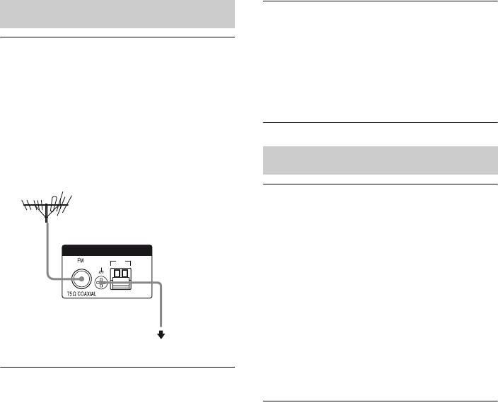
132US
The FM reception is poor.
• Use a 75-ohm coaxial cable (not supplied)
to connect the receiver to an outdoor FM
antennas (aerial) as shown below. If you
connect the receiver to an outdoor antenna
(aerial), ground it against lightning. To
prevent a gas explosion, do not connect the
ground (earth) wire to a gas pipe.
Radio stations cannot be tuned in.
• Check that the antennas (aerials) are
connected securely. Adjust the antennas
(aerials) and connect an external antenna
(aerial), if necessary.
• Keep the satellite radio antenna, away
from the speaker cords and the power cord
to avoid picking up noise.
• The signal strength of the stations is too
weak (when tuning in with automatic
tuning). Use direct tuning.
• Make sure you set the tuning interval
correctly (when tuning in AM stations
with direct tuning).
• No stations have been preset or the preset
stations have been cleared (when tuning
by scanning preset stations). Preset the
stations (page 54).
• Press DISPLAY repeatedly so that the
frequency appears on the display.
The receiver cannot receive satellite
channels at all.
• The receiving condition is not good. Move
the antenna to the place where the
condition is good.
• Check that you subscribed to the satellite
radio service you want (page 55).
The remote does not function.
• Point the remote at the remote sensor on
the receiver.
• Remove any obstacles in the path between
the remote and the receiver.
• Replace all the batteries in the remote with
new ones, if they are weak.
• Make sure you select the correct input on
the remote.
• When you operate a programmed non-
Sony component, the remote may not
function properly depending on the model
and the maker of the component.
Tuner
ANTENNA
AM
Receiver
To ground
Ground wire
(not supplied)
Outdoor FM antenna (aerial)
Remote commander

133US
Additional Information
If there is a malfunction, the display shows a
message. You can check the condition of the
system by the message. See the following table
to solve the problem. If any problem persists,
consult your nearest Sony dealer.
PROTECTOR
Irregular current is output to the speakers, or
upper panel of the receiver is covered with
something. The receiver will automatically
turn off after a few seconds. Check the
speaker connection and turn on the power
again.
For other messages, see “Message list after
Auto Calibration measurement” (page 44),
“DIGITAL MEDIA PORT message list”
(page 52) and “SIRIUS Satellite Radio
message list” (page 62).
If you are unable to remedy the problem using
the troubleshooting guide, clearing the
receiver’s memory may remedy the problem
(page 36). However, note that all memorized
settings will be reset to their initial settings and
you will have to readjust all settings on the
receiver.
If the problem persist, consult your nearest
Sony dealer. Note that if service personnel
changes some parts during repair, these parts
may be retained.
In the event of a problem with S-AIR function,
have a Sony dealer check the entire system
together (S-AIR main unit and S-AIR sub
unit).
Specifications
AUDIO POWER
SPECIFICATIONS
POWER OUTPUT AND TOTAL
HARMONIC DISTORTION:
(Models of area code U only)
With 8 ohm loads, both channels driven, from
20 – 20,000 Hz; rated 100 watts per channel
minimum RMS power, with no more than
0.09% total harmonic distortion from 250
milliwatts to rated output.
Amplifier section
Models of area code U, CA1)
Minimum RMS Output Power
(8 ohms, 20 Hz – 20 kHz, THD 0.09%)
100 W + 100 W
Stereo Mode Output Power
(8 ohms, 1 kHz, THD 1%)
110 W + 110 W
Surround Mode Output Power2)
(8 ohms, 1 kHz, THD 10%)
150 W per channel
1)Measured under the following conditions:
2)Reference power output for front, center, surround
and surround back speakers. Depending on the
sound field settings and the source, there may be
no sound output.
Frequency response
Analog 10 Hz – 70 kHz,
+0.5/–2 dB (with sound
field and equalizer
bypassed)
Error messages
Reference sections for clearing
the receiver’s memory
To clear See
All memorized settings page 36
Customized sound fields page 70
Area code Power requirements
U, CA 120 V AC, 60 Hz
continued

134US
Input
Analog Sensitivity: 500 mV/
50 kohms
S/N3): 96 dB
(A, 500 mV4))
Digital (Coaxial) Impedance: 75 ohms
S/N: 100 dB
(A, 20 kHz LPF)
Digital (Optical) S/N: 100 dB
(A, 20 kHz LPF)
Output (Analog)
AUDIO OUT Voltage: 500 mV/10 kohms
SUBWOOFER Voltage: 2 V/1 kohm
Equalizer
Gain levels ±10 dB, 1 dB step
3)INPUT SHORT (with sound field and equalizer
bypassed).
4)Weighted network, input level.
FM tuner section
Tuning range 87.5 MHz – 108.0 MHz
Antenna (aerial) FM wire antenna (aerial)
Antenna (aerial) terminals
75 ohms, unbalanced
Intermediate frequency
10.7 MHz
AM tuner section
Tuning range
Models of area code U, CA
With 10-kHz tuning scale:
530 kHz – 1,710 kHz
With 9-kHz tuning scale:
531 kHz – 1,710 kHz
Antenna (aerial) Loop antenna (aerial)
Intermediate frequency
450 kHz
Video section
Inputs/Outputs
Video: 1 Vp-p, 75 ohms
COMPONENT VIDEO:
Y: 1 Vp-p, 75 ohms
PB/CB: 0.7 Vp-p, 75 ohms
PR/CR: 0.7 Vp-p, 75 ohms
80 MHz HD Pass Through
General
Power requirements
Power output (DIGITAL MEDIA PORT)
DC OUT: 5V, 0.7 A MAX
Power consumption
Power consumption (during standby mode)
0.9 W (When “Ctrl for
HDMI” and “S-AIR Stby”
is set to “OFF”)
Dimensions (width/height/depth) (Approx.)
17 × 6 1/4 × 12 7/8 inches
(430 × 157.5 × 324.5 mm)
including projecting parts
and controls
Mass (Approx.) 18 lb 16 oz (8.6 kg)
Supplied accessories
Operating instructions (this manual)
Quick Setup Guide (1)
GUI Menu List (1)
FM wire antenna (aerial) (1)
AM loop antenna (aerial) (1)
RM-AAP040 Remote commander (1)
R6 (size-AA) batteries (2)
Optimizer microphone (ECM-AC2) (1)
Design and specifications are subject to
change without notice.
Area code Power requirements
U, CA 120 V AC, 60 Hz
Area code Power consumption
U, CA 250 W
For details on the area code of the
component you are using, see page 4.
Halogenated flame retardants are not used in
the certain printed wiring boards.

135US
Additional Information
Index
Numerics
2-channel 63
5.1 channel 17
7.1 channel 17
A
A/V Sync 78, 86
AM 52, 91
Antenna Aiming 57, 86, 92
Audio settings 78, 86
Auto Calibration settings 72,
84
Auto Tuning 53
B
BI-AMP 73
Bi-amplifier connection 113
Blu-ray disc player 27, 30,
48
BRAVIA Sync
preparing 94
C
Calibration Type 72, 84
Category Mode 58, 92
CD player 23, 48
Changing the display 88
Cinema Studio EX (mode)
67
Clear
memory 36
remote 121
sound field 70
Connection
antennas 35
audio components 23
speakers 19
TV 21
video components 25
Control for HDMI 81
Crossover frequency 75, 85
D
DCAC (Digital Cinema Auto
Calibration) 40
DCS 67
Decode Priority 79, 86
DIGITAL MEDIA PORT
23, 49
DIMMER 111
Direct Tuning 53, 59, 91, 92
Display 10
Distance Unit 76, 85
Dolby Digital EX 69
DTS Neo 6 (Cinema, Music)
66
Dual Mono 78, 86
DVD player 27, 29, 48
DVD recorder 32
Dynamic range compression
76, 84
E
Effect level 77
EQ settings 78, 86
F
FM 52, 91
FM Mode 53, 86
G
GUI (Graphical User
Interface) 37
H
HDMI settings 81, 87
I
Input Assign 109
INPUT MODE 108
iPod 50
L
Level settings 84
LFE (Low Frequency Effect)
10
Lock Code 61
M
Menu 70, 84
Message
Auto Calibration 44
DIGITAL MEDIA
PORT 52
Error 133
SIRIUS 62
Movie 67
Music 67
Muting 48
N
Name Input 49, 55
Neural-THX 66
NIGHT MODE 112
O
Option menu 46
P
Parental Lock 60, 86
Party Mode 104
Phase Audio 75, 84
Phase Noise 75, 84
Position 72, 84
Preset channels 59, 93
Preset Mode 58
Preset stations 54, 91
PRO LOGIC II 66
PRO LOGIC IIx 66
PROTECTOR 133
continued

(1)
Sony Corporation Printed in Malaysia
R
Radio ID 57
Recording 112
Remote 14, 115
Resolution 79, 87
S
S-AIR 97
S-AIR settings 82, 87
Satellite tuner 27, 31, 48
Settings menu 70
SIRIUS Satellite Radio 55,
92
Sleep Timer 111
Sound Field 77, 90
Speaker settings 73, 85
Subwoofer Level 81, 87
Super Audio CD player 23,
48
Surround settings 77, 86
System settings 87
T
Test Tone 75, 84
Tuner 52
Tuner settings 86
Tuning 53, 54
TV 21, 27, 48
U
Up converting 33
V
VCR 32, 48
Video settings 79, 87
