Sony Str Ks370 Operation Manual HT SF370/HT SS370
2015-11-13
: Sony Sony-Str-Ks370-Operation-Manual-820148 sony-str-ks370-operation-manual-820148 sony pdf
Open the PDF directly: View PDF ![]() .
.
Page Count: 76
- Unpacking
- Description and location of parts
- Getting Started
- Playback
- Enjoying Surround Sound
- Tuner Operations
- “BRAVIA” Sync Features
- What is “BRAVIA” Sync?
- Preparing for the “BRAVIA” Sync
- Playing back components with one-touch operation (One-Touch Play)
- Enjoying the TV sound from the speakers connected to the receiver (System Audio Control)
- Turning off the receiver with the TV (System Power Off)
- Using the power saving function (HDMI Pass Through)
- Enjoying the TV sound via an HDMI connection (Audio Return Channel)
- Enjoying optimum sound field for the selected scene (Scene Select)
- Enjoying movies with the optimum sound field (Theater Mode)
- S-AIR Operations
- Advanced Settings
- Additional Information

©2010 Sony Corporation
4-168-166-11(1)
Home Theatre
System
Operating Instructions
HT-SF370
HT-SS370
2US
To reduce the risk of fire or electric
shock, do not expose this apparatus to
rain or moisture.
To reduce the risk of fire, do not cover the
ventilation opening of the apparatus with
newspapers, tablecloths, curtains, etc. Do not place
the naked flame sources such as lighted candles on
the apparatus.
Do not install the appliance in a confined space, such
as a bookcase or built-in cabinet.
To reduce the risk of fire or electric shock, do not
expose this apparatus to dripping or splashing, and
do not place objects filled with liquids, such as
vases, on the apparatus.
As the main plug is used to disconnect the unit from
the mains, connect the unit to an easily accessible
AC outlet. Should you notice an abnormality in the
unit, disconnect the main plug from the AC outlet
immediately.
Do not expose batteries or apparatus with battery-
installed to excessive heat such as sunshine, fire or
the like.
The unit is not disconnected from the mains as long
as it is connected to the AC outlet, even if the unit
itself has been turned off.
To prevent injury, this apparatus must be securely
attached to the floor/wall in accordance with the
installation instructions.
For customers in the United
States and Canada
ENERGY STAR® is a U.S. registered
mark.
As an ENERGY STAR® partner, Sony
Corporation has determined that this
product meets the ENERGY STAR®
guidelines for energy efficiency.
For customers in the United
States
Owner’s Record
The model and serial numbers are located on the rear
of the unit. Record these numbers in the space
provided below. Refer to them whenever you call
upon your Sony dealer regarding this product.
Model No. Serial No.
This symbol is intended to alert the
user to the presence of uninsulated
“dangerous voltage” within the
product’s enclosure that may be of
sufficient magnitude to constitute a
risk of electric shock to persons.
This symbol is intended to alert the
user to the presence of important
operating and maintenance
(servicing) instructions in the
literature accompanying the
appliance.
Important Safety Instructions
1) Read these instructions.
2) Keep these instructions.
3) Heed all warnings.
4) Follow all instructions.
5) Do not use this apparatus near water.
6) Clean only with dry cloth.
7) Do not block any ventilation openings. Install in
accordance with the manufacturer’s instructions.
8) Do not install near any heat sources such as
radiators, heat registers, stoves, or other
apparatus (including amplifiers) that produce
heat.
9) Do not defeat the safety purpose of the polarized
or grounding-type plug. A polarized plug has
two blades with one wider than the other. A
grounding type plug has two blades and a third
grounding prong. The wide blade or the third
prong are provided for your safety. If the
provided plug does not fit into your outlet,
consult an electrician for replacement of the
obsolete outlet.
10)Protect the power cord from being walked on or
pinched particularly at plugs, convenience
receptacles, and the point where they exit from
the apparatus.
11)Only use attachments/accessories specified by
the manufacturer.
WARNING

3US
12)Use only with the cart, stand, tripod, bracket, or
table specified by the manufacturer, or sold with
the apparatus. When a cart is used, use caution
when moving the cart/apparatus combination to
avoid injury from tip-over.
13)Unplug this apparatus during lightning storms or
when unused for long periods of time.
14)Refer all servicing to qualified service personnel.
Servicing is required when the apparatus has
been damaged in any way, such as power-supply
cord or plug is damaged, liquid has been spilled
or objects have fallen into the apparatus, the
apparatus has been exposed to rain or moisture,
does not operate normally, or has been dropped.
The following FCC statement
applies only to the version of
this model manufactured for
sale in the U.S.A. Other
versions may not comply with
FCC technical regulations.
NOTE:
This equipment has been tested and found to comply
with the limits for a Class B digital device, pursuant
to Part 15 of the FCC Rules. These limits are
designed to provide reasonable protection against
harmful interference in a residential installation.
This equipment generates, uses and can radiate radio
frequency energy and, if not installed and used in
accordance with the instructions, may cause harmful
interference to radio communications. However,
there is no guarantee that interference will not occur
in a particular installation. If this equipment does
cause harmful interference to radio or television
reception, which can be determined by turning the
equipment off and on, the user is encouraged to try
to correct the interference by one or more of the
following measures:
– Reorient or relocate the receiving antenna.
– Increase the separation between the equipment
and receiver.
– Connect the equipment into an outlet on a circuit
different from that to which the receiver is
connected.
– Consult the dealer or an experienced radio/TV
technician for help.
CAUTION
You are cautioned that any changes or modifications
not expressly approved in this manual could void
your authority to operate this equipment.
4US
About This Manual
• The instructions in this manual are for model
HT-SF370 and HT-SS370. In this manual, models
of area code CA2 is used for illustration purposes
unless stated otherwise. Any difference in
operation is clearly indicated in the text, for
example, “Models of area code U2 only”.
• The instructions in this manual describe the
controls on the supplied remote. You can also use
the controls on the receiver if they have the same
or similar names as those on the remote.
This receiver incorporates Dolby* Digital and Pro
Logic Surround and the DTS** Digital Surround
System.
* Manufactured under license from Dolby
Laboratories. Dolby, Pro Logic, and the double-
D symbol are trademarks of Dolby Laboratories.
** Manufactured under license under U.S. Patent
#’s: 5,451,942; 5,956,674; 5,974,380;
5,978,762; 6,487,535 & other U.S. and
worldwide patents issued & pending. DTS and
DTS Digital Surround are registered trademarks
and the DTS logos and Symbol are trademarks of
DTS, Inc. © 1996-2008 DTS, Inc. All Rights
Reserved.
This receiver incorporates High-Definition
Multimedia Interface (HDMITM) technology.
HDMI, the HDMI logo and High-Definition
Multimedia Interface are trademarks or registered
trademarks of HDMI Licensing LLC.
“x.v.Color” and “x.v.Color” logo are trademarks of
Sony Corporation.
“BRAVIA” is a trademark of Sony Corporation.
“PLAYSTATION” is a trademark of Sony
Computer Entertainment Inc.
“S-AIR” and its logo are trademarks of Sony
Corporation.
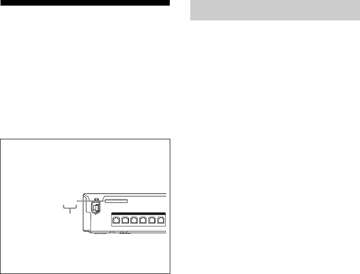
About area codes
The area code of the receiver you purchased is
shown on the upper left portion of the rear panel
(see the illustration below).
Any differences in operation, according to the area
code, are clearly indicated in the text, for example,
“Models of area code AA only”.
FRONT R
SPEAKERS
FRONT L SUR R SUR L CENTER
SUBWOOFER
4-XXX-XXX-XX(X) AA
Area code
On Copyrights

5US
Table of Contents
Unpacking ..................................................... 6
Description and location of parts .................. 8
Getting Started
1: Installing the speakers............................. 15
2: Connecting the speakers ......................... 18
3: Connecting the TV.................................. 19
4: Connecting the audio/video
components ............................................ 20
5: Connecting the antennas ......................... 24
6: Preparing the receiver ............................. 24
7: Calibrating the appropriate settings
automatically
(AUTO CALIBRATION) ...................... 25
Playback
Selecting a component ................................ 29
Enjoying sound/images from the
components connected to the receiver ... 30
Enjoying Surround Sound
Selecting the sound field ............................. 33
Enjoying the sound at low volume
(NIGHT MODE).................................... 34
Tuner Operations
Listening to FM/AM radio.......................... 35
Presetting radio stations .............................. 37
“BRAVIA” Sync Features
What is “BRAVIA” Sync? .......................... 39
Preparing for the “BRAVIA” Sync ............. 39
Playing back components with one-touch
operation (One-Touch Play)................... 41
Enjoying the TV sound from the speakers
connected to the receiver
(System Audio Control) ......................... 41
Turning off the receiver with the TV
(System Power Off)................................43
Using the power saving function
(HDMI Pass Through)............................44
Enjoying the TV sound via an HDMI
connection (Audio Return Channel).......45
Enjoying optimum sound field for the
selected scene (Scene Select) .................46
Enjoying movies with the optimum
sound field (Theater Mode)....................46
S-AIR Operations
About S-AIR products.................................47
Setting up an S-AIR product .......................48
Enjoying the system’s sound in another
room .......................................................52
Stabilizing S-AIR reception ........................54
Changing the channel for better sound
transmission............................................55
Enjoying the S-AIR receiver while the
S-AIR main unit is in standby mode ......56
Advanced Settings
Changing the input button assignments.......57
Settings and adjustments using the
amplifier menu .......................................58
Additional Information
Glossary.......................................................63
Precautions ..................................................65
Troubleshooting...........................................67
Specifications ..............................................72
Index............................................................75

6US
Unpacking
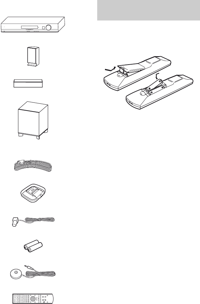
Be sure that you have the following items in your package.
HT-SF370 only
• Receiver (STR-KS370) (1)
• Front speakers
(SS-MSP37F) (2)
•Center speaker
(SS-CNP37) (1)
• Surround speakers
(SS-SRP37F) (2)
• Subwoofer (SS-WP37) (1)
• Speaker cords (5, Red/
White/Grey/Blue/Green)
• Foot pads (Big × 4, Small
× 4)
• Bases (Large × 2, Small ×
2)
• Posts (Long × 2, Short × 2)
• Post covers (4)
• Brackets (4)
• Screws (Large) (8)
• Screws (Small) (12)
• AM loop antenna (1)
• FM wire antenna (1)
• R6 (size-AA) batteries (2)
• Optimizer microphone
(ECM-AC2) (1)
• Remote commander
(RM-AAU071) (1)
• Operating Instructions
(this manual)
• Quick Setup Guide (1)
MASTER VOLUME
POWER /
ACTIVE STANDBY
.
mM
>
Xx
BD DVD SAT/
CATV
VIDEO SA-CD/
CD
DMPORT TUNER
O
TV
MENU
7US
HT-SS370 only
• Receiver (STR-KS370) (1)
• Front/Surround speakers (SS-TSB101) (4)
• Center speaker (SS-CTB101) (1)
• Subwoofer (SS-WSB101) (1)
• Speaker cords (5, Red/White/Grey/Blue/
Green)
• AM loop antenna (1)
• FM wire antenna (1)
• R6 (size-AA) batteries (2)
• Optimizer microphone (ECM-AC2) (1)
• Remote commander (RM-AAU071) (1)
• Operating Instructions (this manual)
• Quick Setup Guide (1)
Insert two R6 (size-AA) batteries in the
RM-AAU071 Remote Commander.
Observe the correct polarity when installing
batteries.
Notes
• Do not leave the remote in an extremely hot or
humid place.
• Do not use a new battery with old ones.
• Do not mix manganese batteries and other kinds of
batteries.
• Do not expose the remote sensor to direct sunlight
or lighting apparatuses. Doing so may cause a
malfunction.
• If you do not intend to use the remote for an
extended period of time, remove the batteries to
avoid possible damage from battery leakage and
corrosion.
• When you replace the batteries, the remote buttons
may be reset to their initial settings. If this
happens, reassign the buttons again (page 57).
• When the remote no longer operates the receiver,
replace all the batteries with new ones.
MASTER VOLUME
POWER /
ACTIVE STANDBY
.
mM
>
Xx
BD DVD SAT/
CATV
VIDEO SA-CD/
CD
DMPORT TUNER
O
TV
MENU
Inserting batteries into the
remote
8US
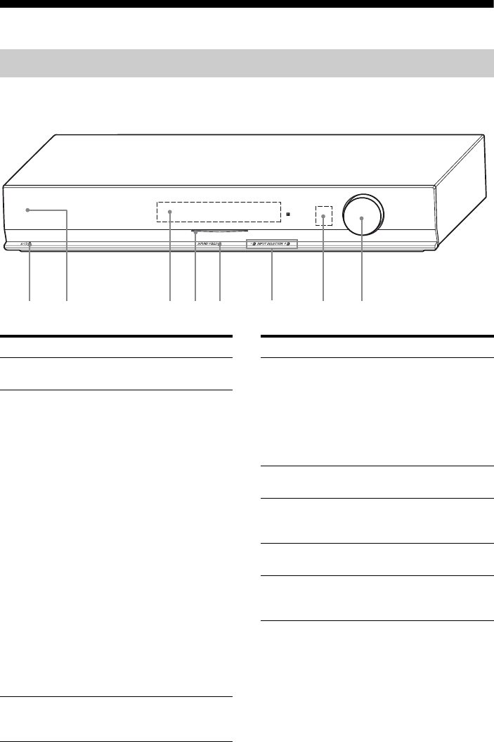
Description and location of parts
Front view
Receiver
MASTER VOLUME
POWER /
ACTIVE STANDBY
1 2 3 4 65 78
Name Function
A?/1
(on/standby)
Turns the receiver on or off
(page 24, 31, 58).
BPOWER/
ACTIVE
STANDBY
indicator
Lights up as follows:
Green:
No light:
Amber:
The receiver is
turned on.
The receiver is in
standby mode, and
Control for HDMI
and S-AIR standby
mode are set to off.
The receiver is in
standby mode, and
Control for HDMI
and/or S-AIR
standby mode are set
to on. However, the
indicator lights off
when “PASS THRU”
is set to “THRU
AUTO” and there is
no signals detected.
Note
If the POWER/ACTIVE
STANDBY indicator is
flashing, see page 71.
CDisplay Displays the current status of
the selected component or a list
of selectable items (page 9).
Name Function
DWhite indicator Lights up when the
receiver is on and DSPL is
set to on in DISPLAY
function (page 62). Lights
off when the receiver is in
standby mode or DSPL is
set to off in DISPLAY
function.
ESOUND FIELD Selects the sound field
(page 33).
FINPUT
SELECTOR +/–
Selects the input source to
playback (page 29, 31, 32,
35, 37, 38).
GRemote sensor Receives signals from the
remote.
HMASTER
VOLUME
Adjusts the volume level
of all speakers at the same
time (page 30, 32, 67).
9US
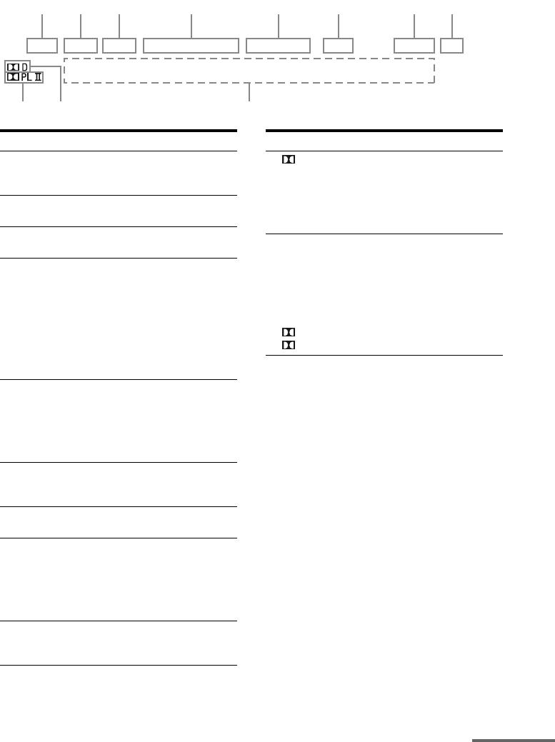
About the indicators on the display
LPCM NIGHT SLEEP HDMI COAX OPT TUNED ST S-AIR MUTING DTS
123 4 5 6 78
q;
qa 9
Name Function
ALPCM Lights up when Linear PCM
(Pulse Code Modulation) signals
are input.
BNIGHT Lights up when the Night Mode
function is set to on (page 34).
CSLEEP Lights up when the sleep timer is
activated (page 62).
DInput
indicators
HDMI
COAX
OPT
Light up when the digital signal
is input.
Digital signal is input through
the HDMI IN jack.
Digital signal is input through
the COAX IN jack.
Digital signal is input through
the OPT IN jack.
ETuning
indicators
TUNED
ST
Light up to indicate the current
status of the radio station (page
35).
When receives a radio station.
When broadcasts in stereo mode.
FS-AIR Lights up when the S-AIR
transmitter (not supplied) is
connected.
GMUTING Lights up when the muting
function is activated.
HDTS Lights up when the receiver is
decoding DTS signals.
Note
When playing a DTS format
disc, be sure that you have made
digital connections.
IMessage
display area
Displays the volume level,
selected input source, audio
input signal, etc.
Name Function
J DLights up when the receiver is
decoding Dolby Digital signals.
Note
When playing a Dolby Digital
format disc, be sure that you
have made digital connections.
KDolby Pro
Logic
indicators
PL
PLII
Lights up one of the respective
indicators when the receiver
applies Dolby Pro Logic
processing to 2 channel signals
in order to output the center and
surround channel signals.
Dolby Pro Logic
Dolby Pro Logic II
continued
10US
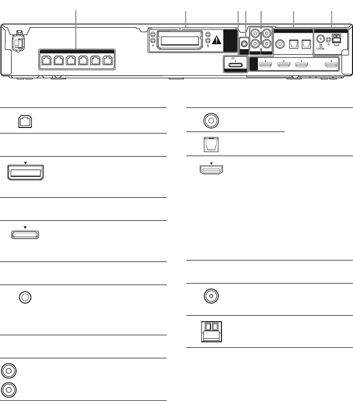
Rear panel
AM
ANTENNA
AUTO
CAL MIC
HDMI
EZW-T100
FRONT R
SPEAKERS
FRONT L SUR R SUR L CENTER
SUBWOOFER
DMPORT
DC5V 0.7A MAX
DVD IN BD IN SAT/CATV IN TV OUT
ARC
AUDIO IN
VIDEO
L
R
SA-CD
/
CD
COAX IN
SAT/CATV TV
OPT IN OPT IN
AUDIO IN
TV
DIGITAL
1
234 5 6 7
ASPEAKERS section
Connects to the supplied speakers
and subwoofer (page 18).
BS-AIR
EZW-T100
slot
Connects to a
wireless transmitter
(not supplied)
(page 48).
CDMPORT
DMPORT
jack
Connects to a
DIGITAL MEDIA
PORT adapter (page
20).
DAUTO CALIBRATION
AUTO CAL
MIC jack
Connects to the
supplied optimizer
microphone for the
Auto Calibration
function (page 26).
EAUDIO INPUT section
AUDIO IN
jacks
Connects to a Super
Audio CD player,
CD player, etc.
(page 19, 20).
White (L)
Red (R)
FDIGITAL INPUT/OUTPUT section
COAX IN
jack
Connects to a
satellite tuner, etc.
(page 23).
OPT IN jacks
HDMI IN/
OUT jacks
Connects to a DVD
player, satellite
tuner, or a Blu-ray
Disc player. The
image is output to a
TV or a projector
while the sound can
be output from a TV
or/and speakers
connected to this
receiver (page 21).
GANTENNA section
FM
ANTENNA
jack
Connects to the
supplied FM wire
antenna (page 24).
AM
ANTENNA
terminals
Connects to the
supplied AM loop
antenna (page 24).
11US
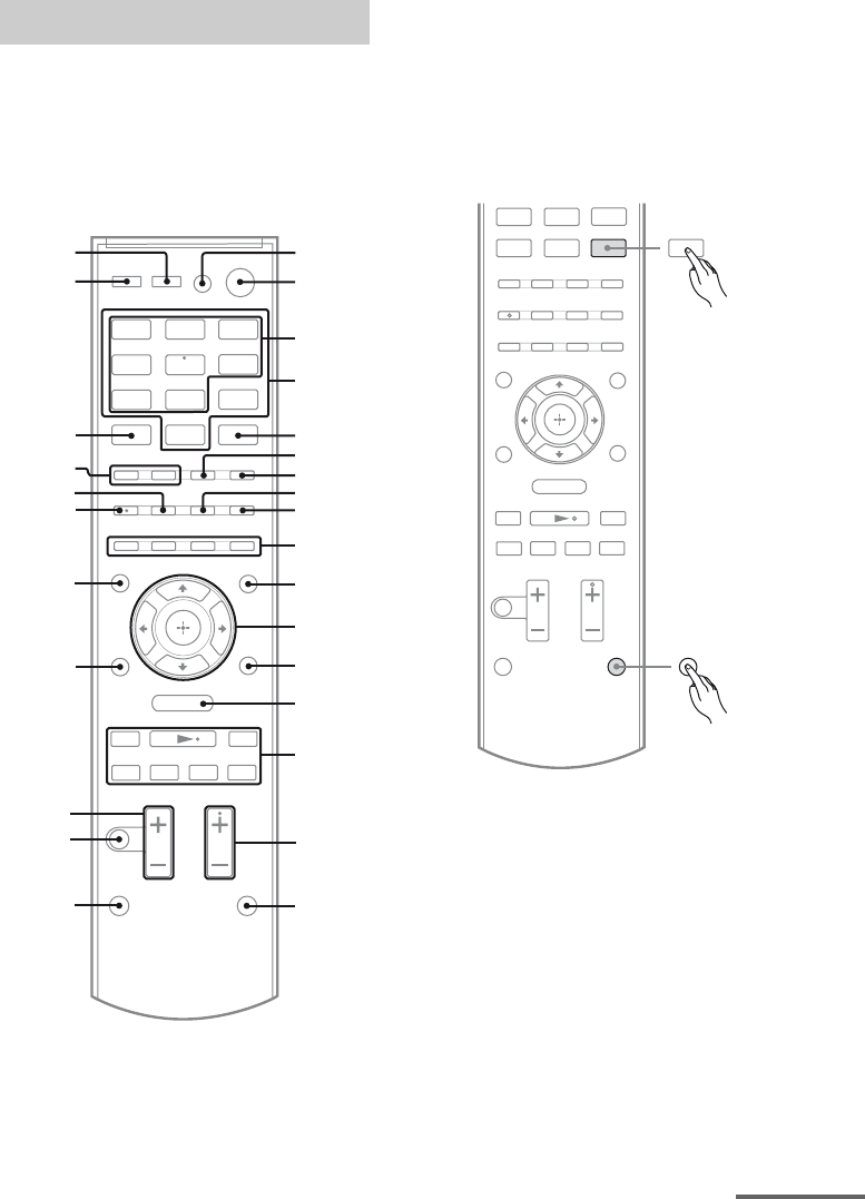
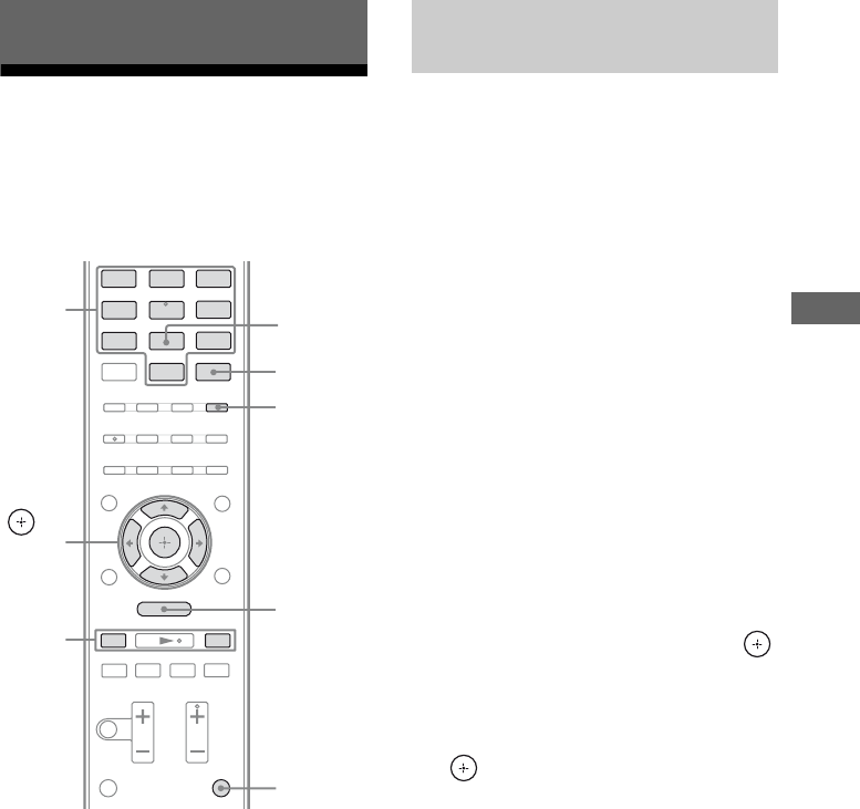
You can use the supplied remote
RM-AAU071 to operate the receiver and to
control the Sony audio/video components that
the remote is assigned to operate (page 57).
RM-AAU071
Notes on using SHIFT (Q) and
TV (R) button
SHIFT (Q) button
Press and hold SHIFT (Q), then press the
button with pink printing that you want to use.
Example: Press and hold SHIFT (Q), then
press ENTER (E).
Remote commander
.
mM
>
Xx
BD DVD SAT/
CATV
VIDEO SA-CD/
CD
DMPORT TUNER
O
TV
MENU
qk
w;
ql
wa
wj
wk
wh
wg
wf
ws
wd
1
2
3
4
6
7
9
qs
0
qa
qf
qg
qh
qj
8
5
qd
SHIFT
.
mM
>
Xx
DMPORT TUNER
O
MENU
ENTER
continued
12US
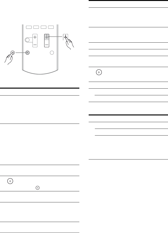
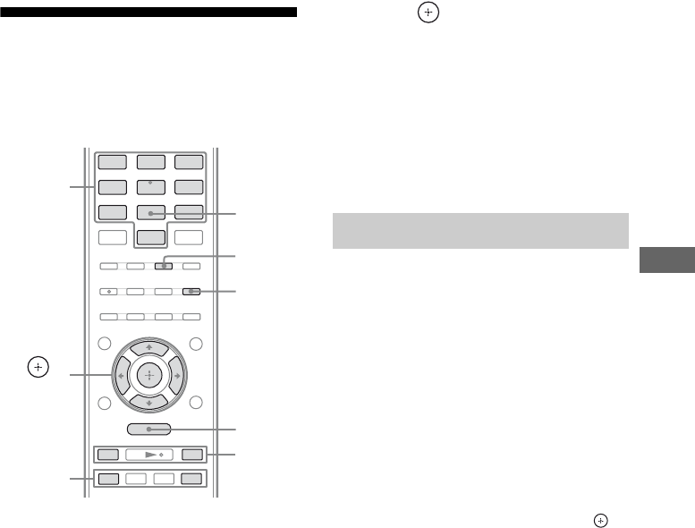
TV (R) button
Press and hold TV (R), then press the button
with yellow printing to control the TV.
Example: Press and hold TV (R), then press
TV CH + (P).
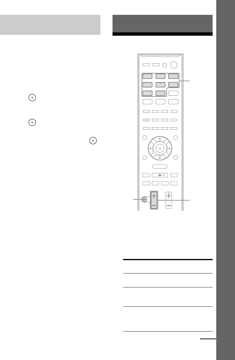
Basic operations
Tuner operations
DMPORT operations
To control the component
1Press one of the input buttons
(TV, BD, DVD or SAT/CATV)
(C) to select the component
you want to operate.
The component assigned to the selected
input button becomes operable.
2Referring to the following table,
press the corresponding
button for the operation.
Remote button Function
B?/1
(on/standby)
Turns the receiver on or off.
To turn off all Sony
components, press ?/1 (B)
and AV ?/1 (A) at the same
time (SYSTEM
STANDBY).
CInput buttons
(VIDEO*)
Selects the component you
want to use. The buttons are
initial assigned to control
Sony components.
You can change the button
assignments following the
steps in “Changing the input
button assignments” on page
57.
KAMP MENU Displays the menu of the
receiver.
L
V/v/B/b
Press V, v, B or b to select
the menu items. Then, press
to enter the selection.
PSOUND FIELD
+*/–
Selects a sound field.
SMUTING Activates the muting
function.
Press MUTING again to
restore the sound.
TMASTER VOL
+/–
Adjusts the volume level of
all speakers at the same time.
.>
Xx
TV CH
TV
,
Remote button Function
DNumeric
buttons
(number 5*)
Press and hold SHIFT (Q),
then press the numeric
buttons (D) to preset/tune
to the preset stations.
EENTER Press and hold SHIFT (Q),
then press ENTER (E) to
enter the selection.
FMEMORY Stores a station.
GD.TUNING Enters direct tuning mode.
IDISPLAY Displays information during
TUNER function.
L
V/v/B/b
Selects a menu item and
enters the selection.
NMENU/HOME Displays the tuner menu.
OPRESET +/– Selects a preset station.
TUNING +/– Scans a station.
Remote button Function
O./>Skips the track.
m/MFast reverse or fast forward.
N* (playback)/
X (pause, press
again to resume
normal playback)/
x (stop)
Play mode buttons.
,
13US
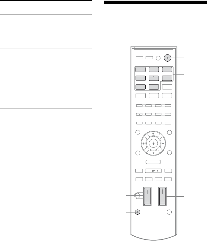
Common operations
To control the TV
Press and hold TV (yellow) button (R), then
press the button with yellow printing to control
the TV.
Remote button Function
ATV ?/1
AV ?/1
(on/standby)
Turns on or off the Sony TV
or audio/video components
that the remote is assigned to
operate (page 57).
Press ?/1 (B) and TV ?/1/
AV ?/1 (A) at the same
time to turn off the receiver
and other components that
the remote is assigned to
operate (SYSTEM
STANDBY).
DNumeric
buttons
(number 5*)
Press and hold SHIFT (Q),
then press the numeric
buttons (D) to select
channels and tracks directly.
EENTER Press and hold SHIFT (Q),
then press ENTER (E) to
enter the selection.
JColor buttons Displays an operation guide
on the TV screen when the
color buttons are available.
Follow the operation guide
to perform a selected
operation.
L
V/v/B/b
Selects a menu item and
enters the selection.
Remote button Function
DNumeric
buttons
(number 5*)
Selects channel. Press
ENTER (E) to change
channels immediately.
IDISPLAY – Displays the TV’s
information on the TV
screen. (Displays the
current channel number,
etc.)
– Press AMP MENU (K),
then press DISPLAY (I)
to display the input stream
information of the TV
when TV is connected via
TV OPT IN jack.
,
Remote button Function
MTOOLS/
OPTIONS
Enables you to access
various viewing options and
change/make adjustments
according to the source and
screen format.
NMENU/HOME Allows you to select
channels or input sources and
change the settings for your
TV.
PTV CH +*/– Selects the next (+) or
previous (–) channel.
SMUTING Activates the muting
function.
TTV VOL +/– Adjusts the volume level.
UO RETURN/
EXIT
Returns to the previous
screen of any displayed
menu.
VGUIDE Displays the guide when you
are watching analog or
digital channels.
WAUDIO* Selects the sound from the
speaker for a stereo or
bilingual broadcast.
wj THEATER Sets the optimal picture
settings automatically for
watching movies, when you
connect a Sony TV that is
compatible with the
THEATER button function.
Also, audio is automatically
switched to the audio output
of this receiver when you
connect the TV and the
receiver with HDMI
connection, and the Control
for HDMI function is set to
on.
wk INPUT Selects the TV input signal.
continued

14US
To control the DVD player/recorder,
Blu-ray Disc player/recorder
To control the HDD/DVD COMBO
To control the SAT/CATV
* These buttons (VIDEO/5, AUDIO, N, SOUND
FIELD +/TV CH +) have tactile dots. Use the
tactile dots as references when operating the
receiver.
Notes
• Some functions explained in this section may not
work depending on the model.
• The above explanation is intended to serve as an
example only. Therefore, depending on the
component, the above operation may not be
possible or may operate differently than described.
In that case, use the remote commander supplied
with the component.
Remote button Function
HANGLE Switches to other viewing
angles when multi-angle are
recorded on a Blu-ray Disc
or DVD.
IDISPLAY – Displays the playback
information.
– Press AMP MENU (K),
then press DISPLAY (I)
to display the input stream
information for Blu-ray
Disc or DVD.
MTOOLS/
OPTIONS
Enables you to access
various viewing options and
change/make adjustments
according to the source and
screen format.
NMENU/HOME Displays the menu.
O.Skips chapter.
>Skips forward to the next
available chapter.
m/MFast reverse or fast forward
the disc when pressed
during playback.
N* (playback)/
X (pause, press
again to resume
normal playback)/
x (stop)
Play mode buttons.
UO RETURN/
EXIT
Returns to the previous
screen of any displayed
menu.
VGUIDE Displays the guide when
you are watching analog or
digital channels.
WAUDIO* Selects the sound from the
speaker for a stereo or
bilingual broadcast.
XSUBTITLE Selects the subtitle language
when multi-lingual subtitles
are recorded on a Blu-ray
Disc or DVD.
YTOP MENU Displays the top menu or
disc menu.
POP UP/MENU
ZCLEAR Clear a mistake when you
press the incorrect numeric
button.
Remote button Function
NMENU/HOME Displays the menu.
O./>Specifies the previous or
next chapter or track.
m/MFast reverse or fast forward
the disc when pressed
during playback.
N* (playback)/
X (pause, press
again to resume
normal playback)/
x (stop)
Play mode buttons.
YTOP MENU Displays the top menu or
disc menu.
POP UP/MENU
Remote button Function
IDISPLAY – Displays the information
during SAT/CATV
function.
– Press AMP MENU (K),
then press DISPLAY (I)
to display the input stream
information for satellite
tuner or cable television
tuner.
NMENU/HOME Displays the menu.
VGUIDE Displays the guide menu.
15US
Getting Started
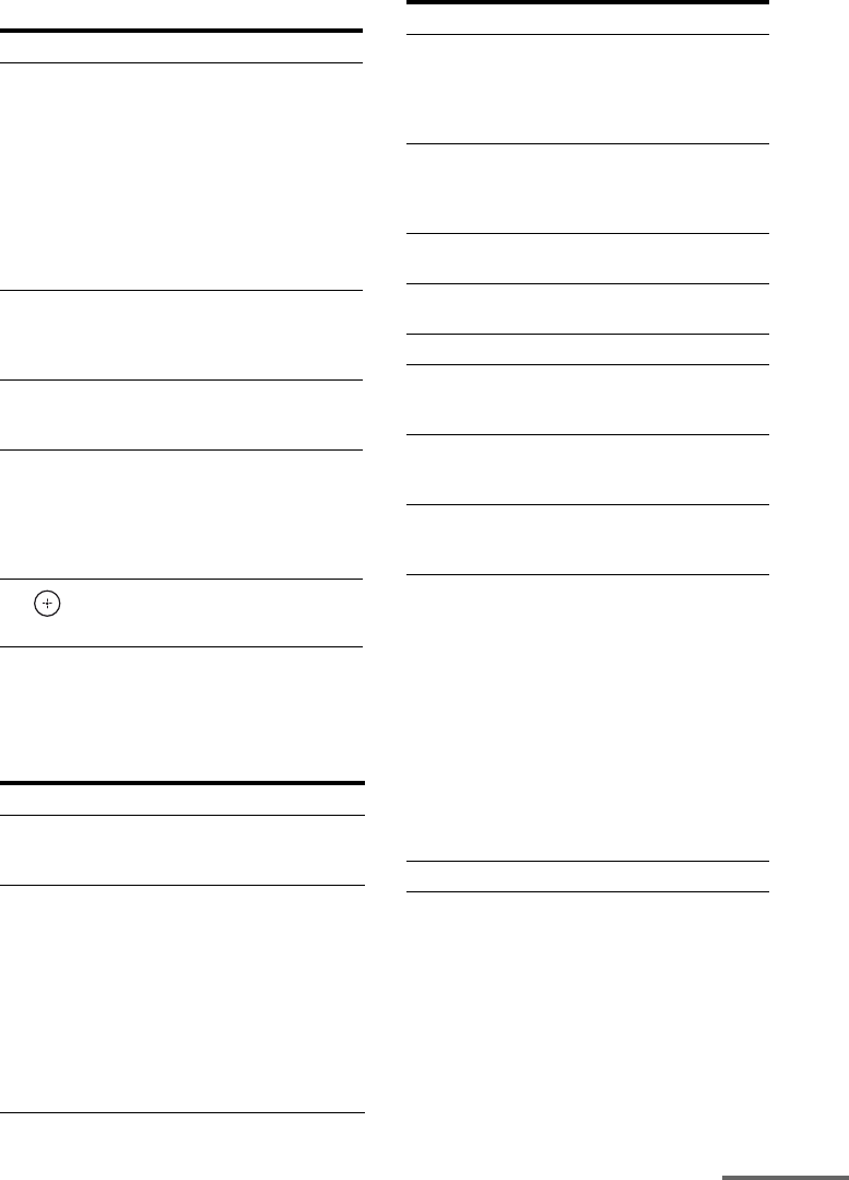
1: Installing the speakers
This receiver allows you to use a 5.1 channel
speaker system. To fully enjoy theater-like
multi channel surround sound, be sure to
connect all the speakers (two front speakers, a
center speaker, and two surround speakers)
and a subwoofer (5.1 channel).
You can place your speakers as shown below.
AFront speaker (left)
BFront speaker (right)
CCenter speaker
DSurround speaker (left)
ESurround speaker (right)
FSubwoofer
HT-SF370 only
HT-SS370 only
Notes
• Be sure to use the supplied speakers.
• For HT-SF370, do not lean on the speaker as it
may fall down.
Tips
• The angle A should be the same.
• Since the subwoofer does not emit highly
directional signals, you can place it wherever you
want.
Getting Started
30˚30˚
100˚-120˚100˚-120˚
A A
16US
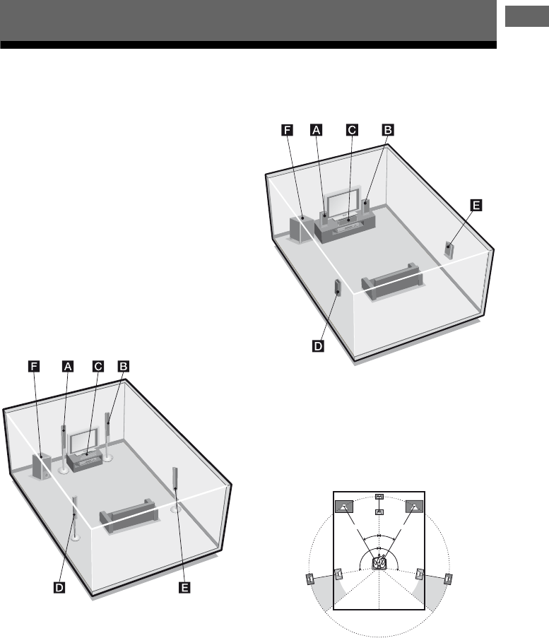
HT-SF370 only
Before you install the center speaker and the
subwoofer, be sure to attach the supplied foot
pads to prevent vibration or movement as
shown in the illustration below.
Note
Attach the small foot pads to the center speaker and
big foot pads to the subwoofer.
For greater flexibility in positioning the
speakers, you are recommended to use the
speaker stand as below.
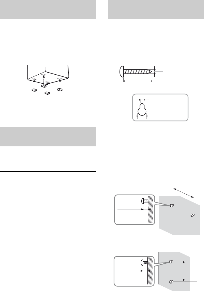
You can install your speakers on the wall.
1Prepare screws (not supplied)
that are suitable for the hook on
the back of each speaker. See
the illustrations below.
2Fasten the screws to the wall.
The screws should protrude
7/32 in to 9/32 in (5 mm to
7 mm).
HT-SF370 only
For the center speaker
For the front speakers
Installing the speakers on a flat
surface
Installing the speakers on the
speaker stand
Model Speaker stand
HT-SF370 Supplied. For details, refer to
the supplied Quick Setup
Guide.
HT-SS370 Optional WS-FV11 or
WS-FV10D speaker stand
(available only in certain
countries).
For details, refer to the
operating instructions supplied
with the speaker stand.
Installing the speakers on the
wall
3/16 in (4 mm)
more than 1 in (25 mm)
7/32 in (5 mm)
13/32 in (10 mm)
Hook on the back of the speaker
7/32 in to 9/32 in
(5 mm to 7 mm)
6 3/8 in
(160 mm)
7/32 in to 9/32 in
(5 mm to 7 mm)
8 5/8 in
(217 mm)
17US
Getting Started
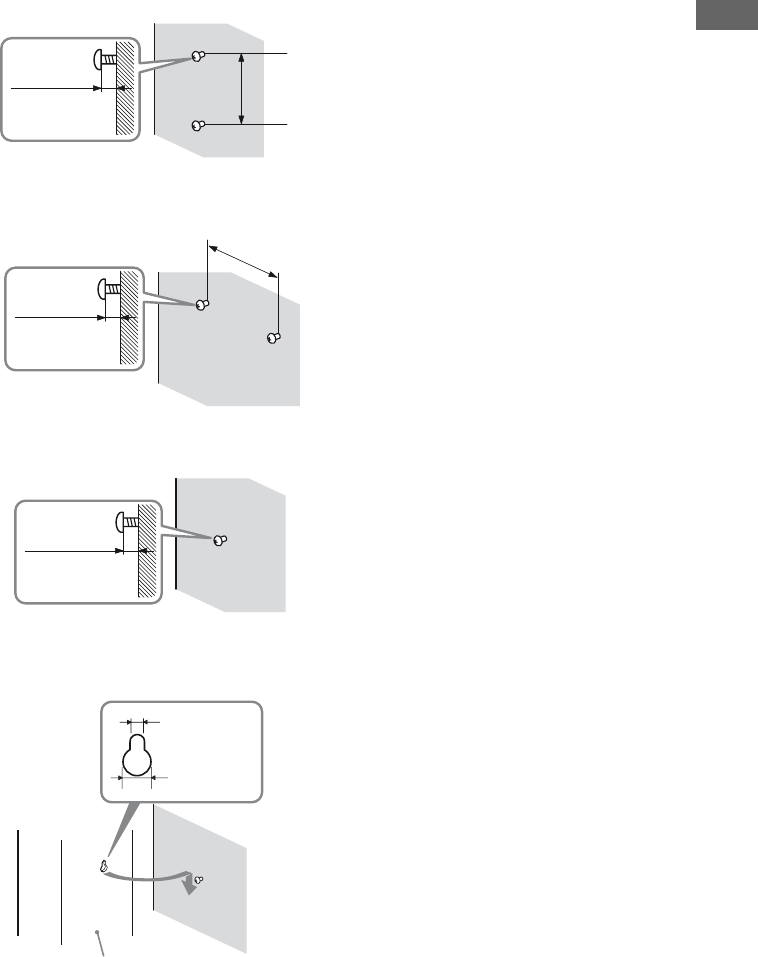
For the surround speakers
HT-SS370 only
For the center speaker
For the front speakers and
surround speakers
3Hang the speakers on the
screws.
Notes
• Use screws that are suitable for the wall material
and strength. As a plaster board wall is especially
fragile, attach the screws securely to a beam and
fasten them to the wall. Install the speakers on a
vertical and flat wall where reinforcement is
applied.
• Contact a screw shop or installer regarding the
wall material or screws to be used.
• Sony is not responsible for accident or damage
caused by improper installation, insufficient wall
strength or improper screw installation, natural
calamity, etc.
• For HT-SF370, if you install the speakers on the
wall, you do not need to attach the supplied
speaker stand.
7/32 in to 9/32 in
(5 mm to 7 mm)
4 in
(100 mm)
7/32 in to 9/32 in
(5 mm to 7 mm)
8 5/8 in
(219 mm)
7/32 in to 9/32 in
(5 mm to 7 mm)
7/32 in (5 mm)
13/32 in
(10 mm)
Rear of speaker
18US
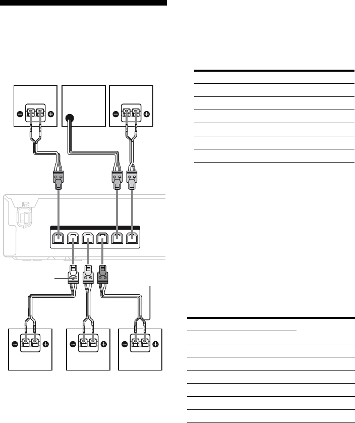
2: Connecting the
speakers
Before connecting the cords, be sure to
disconnect the AC power cord.
AFront speaker (left)
BFront speaker (right)
CCenter speaker
DSurround speaker (left)
ESurround speaker (right)
FSubwoofer
Notes on speaker cords
• The connector of the speaker cords are the
same color as the speaker jack to be
connected. When connecting a speaker cord,
be sure to match the colored connector to the
speaker jack on the receiver:
• Be sure to match the speaker cords to the
appropriate terminals on the speakers:
– the speaker cord with the color tube to e
terminal, and the speaker cord without the
color tube to E terminal (for HT-SS370).
– the speaker cord with a stripe line to E
terminal, and the speaker cord without a
stripe line to e terminal (for HT-SF370).
To connect the speakers
correctly
Check the speaker type by referring to the
speaker label at the rear panel of the speakers.
* This speaker does not have character on the
speaker label. For details on the speaker type, see
page 6 (for HT-SF370) or page 7 (for HT-SS370).
FRONT R
SPEAKERS
CENTERFRONT L SUR R SUR L
SUBWOOFER
E
B
ASpeaker cord (supplied)
A
A
Connector
FC
D
A
AA
Color tube
Connector Speaker jack
Red FRONT R
White FRONT L
Grey SUR R
Blue SUR L
Purple SUBWOOFER
Green CENTER
Character on speaker label Speaker type
HT-SF370 HT-SS370
L FRONT L Front left
R FRONT R Front right
–* CENTER Center
SL SUR L Surround left
SR SUR R Surround right
–* –* Subwoofer
19US
Getting Started
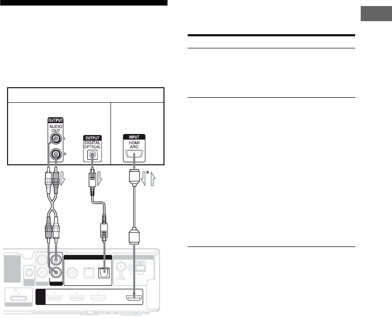
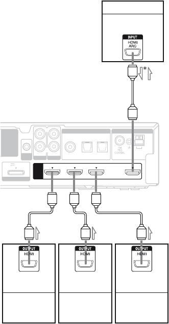
3: Connecting the TV
You can watch the selected input image when
you connect the HDMI OUT jack to a TV.
Before connecting the cords, be sure to
disconnect the AC power cord.
* When you use Audio Return Channel (ARC)
function, the audio signal is output from the TV to
the receiver.
It is not necessary to connect all the cords.
Connect audio and video cords according to
the jacks of your components.
Notes
• Be sure to turn on the receiver when the video and
audio signals of a playback component are being
output to a TV via the receiver. Unless the power is
turned on, neither video nor audio signals will be
transmitted.
• When connecting optical digital cords, insert the
plugs straight in until they click into place.
• Do not bend or tie optical digital cords.
Tip
All the digital audio jacks are compatible with
32 kHz, 44.1 kHz, 48 kHz, and 96 kHz sampling
frequencies.
AM
ANTENNA
AUTO
CAL MIC
HDMI
EZW-T100
DMPORT
DC5V 0.7A MAX
DVD IN BD IN SAT/CATV IN TV OUT
ARC
AUDIO IN
VIDEO
R
SA-CD
/
CD
COAX IN
SAT/CATV TV
OPT IN OPT IN
AUDIO IN
TV
DIGITAL
L
TV
Audio signal
A
AAudio cord (not supplied)
BOptical digital cord (not supplied)
CHDMI cable (not supplied)
Sony recommends that you use an HDMI-
authorized cable or Sony HDMI cable.
Audio/video
signals
C
l : Signal flow
B
Connect To
A or Boutput the TV sound via the
speakers connected to the receiver.
Be sure to turn off the TV’s volume
or activate the TV’s muting
function.
Coutput the image to a TV while the
sound can be output from a TV
or/and speakers connected to the
receiver.
When the TV is compatible with
Audio Return Channel (ARC)
function, you can output the TV
sound via the speakers connected
to the receiver without connecting
A or B. For details, see
“Enjoying the TV sound via an
HDMI connection (Audio Return
Channel)” (page 45).
Be sure to turn off the TV’s volume
or activate the TV’s muting
function.
20US
4: Connecting the audio/
video components
This section describes how to hook up your
components to this receiver. Before you begin,
see “Component to be connected” below for
the pages which describe how to connect the
audio/video components.
Before connecting the cords, be sure to
disconnect the AC power cord.
After hooking up all your components,
proceed to “5: Connecting the antennas” (page
24).
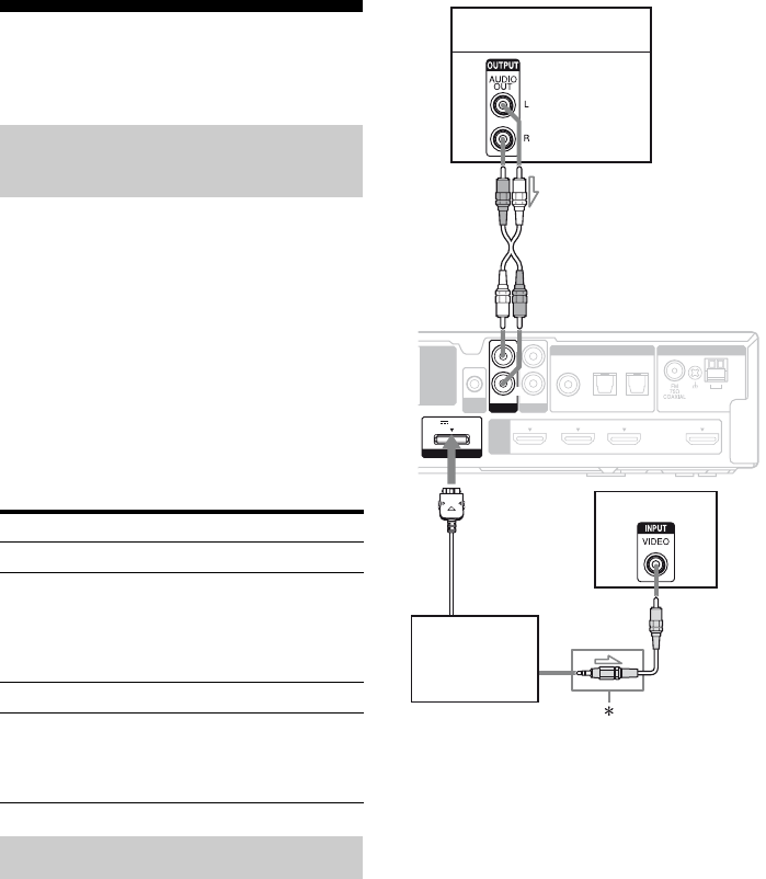
Component to be connected
The following illustration shows how to
connect audio components such as Super
Audio CD player or CD player and DIGITAL
MEDIA PORT adapter.
You can also view the images on the TV
screen by connecting the video output of the
DIGITAL MEDIA PORT adapter to the video
input of the TV. However, depending on the
DIGITAL MEDIA PORT adapter, video
output may not be possible.
* The type of connector varies depending on the
DIGITAL MEDIA PORT adapter.
For details, refer to the operating instructions
supplied with the DIGITAL MEDIA PORT
adapter.
How to hook up your
components
To connect See
TV page 19
Audio components
• Super Audio CD player,
CD player
• DIGITAL MEDIA PORT
adapter
page 20
Components with HDMI jack page 21
Video components
• DVD player, DVD recorder
• Satellite tuner, cable television
tuner
page 23
Connecting audio components
AM
ANTENNA
AUTO
CAL MIC
HDMI
EZW-T100
DC5V 0.7A MAX
DVD IN BD IN SAT/CATV IN TV OUT
ARC
AUDIO IN
VIDEO
R
SA-CD
/
CD
COAX IN
SAT/CATV TV
OPT IN OPT IN
AUDIO IN
TV
DIGITAL
L
DMPORT
Super Audio CD player,
CD player
Audio signal
A
AAudio cord (not supplied)
BVideo cord (not supplied)
B
TV
DIGITAL MEDIA
PORT adapter
l : Signal flow
21US
Getting Started
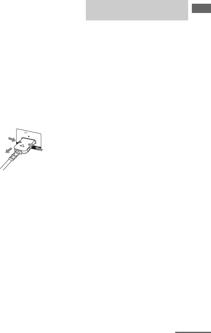
Notes on connecting DIGITAL
MEDIA PORT adapter
• Do not connect or disconnect the DIGITAL
MEDIA PORT adapter while the receiver is
turned on.
• Be sure to make DMPORT connections
firmly, insert the connector straight in.
• As the connector of the DIGITAL MEDIA
PORT adapter is fragile, be sure to handle
with care when placing or moving the
receiver.
• When connecting the DIGITAL MEDIA
PORT adapter, be sure the connector is
inserted with the arrow mark facing towards
the arrow mark on the DMPORT jack. To
detach the DIGITAL MEDIA PORT
adapter, press and hold both sides of the
connector and then pull out the connector.
HDMI is the abbreviated name for High-
Definition Multimedia Interface. It is an
interface which transmits video and audio
signals in digital format.
Sony recommends that you connect
components to the receiver using an HDMI
cable.
By connecting Sony “BRAVIA” Sync-
compatible components using HDMI cables,
operations can be simplified. See ““BRAVIA”
Sync Features” (page 39).
HDMI features
• A digital audio signals transmitted by HDMI
can be output from the speakers connected to
the receiver. This signal supports Dolby
Digital, DTS and Linear PCM.
• This receiver supports Deep Color and
xvYCC transmission.
Notes on connecting cables
• Use a High Speed HDMI cable. If you use a
Standard HDMI cable, 1080p or Deep Color
images may not be displayed properly.
• Sony recommends that you use an HDMI
authorized cable or Sony HDMI cable.
• We do not recommend using an HDMI-DVI
conversion cable. When you connect an
HDMI-DVI conversion cable to a DVI-D
component, the sound and/or the image may
not be output.
DMPORT
DC5V 0.7A MAX
2
1
1
Connecting components with
HDMI jacks
continued
22US
* When you use Audio Return Channel (ARC)
function, the audio signal is output from the TV to
the receiver.
Notes
• When the TV is compatible with Audio Return
Channel (ARC) function, the TV sound will
automatically output from the speakers connected
to the receiver. If not, see page 19 for the audio
connection of TV to the receiver. Be sure to set
“ARC” to “ARC ON” in SET HDMI menu (page
45).
• All the HDMI jacks on the receiver function in the
same way. For example, you can connect a
“PlayStation 3” etc., to any available HDMI jack.
Notes on HDMI connections
• An audio signal input to the HDMI IN jack
is output from the SPEAKERS jacks and
HDMI OUT jack. It is not output from any
other audio jacks.
• Video signals input to the HDMI IN jack can
only be output from the HDMI OUT jack.
• The multi/stereo area audio signals of a
Super Audio CD are not output.
• Audio signals (sampling frequency, bit
length, etc.) transmitted from an HDMI jack
may be suppressed by the connected
component. Check the setup of the
connected component if the image is poor or
the sound does not come out of a component
connected via the HDMI cable.
• Sound may be interrupted when the
sampling frequency, the number of channels
or the audio format of the audio output
signals from the playback component is
switched.
• When the connected component is not
compatible with copyright protection
technology (HDCP), the image and/or the
sound from the HDMI OUT jack may be
distorted or may not be output.
In this case, check the specification of the
connected component.
• You can enjoy multi channel Linear PCM
only with an HDMI connection.
• Set the image resolution of the playback
component to 720p, 1080i or 1080p when
you output 96 kHz multi channel sound over
an HDMI connection.
• You may need to make certain settings on
the image resolution of the player before you
can enjoy multi channel Linear PCM. Refer
to the operating instructions of the player.
• Refer to the operating instructions of each
component connected for details.
• Not every HDMI component supports all
functions that are defined by the specified
HDMI version. For example, components
that support HDMI, version 1.4, may not
support Audio Return Channel (ARC).
AM
ANTENNA
AUTO
CAL MIC
HDMI
EZW-T100
DMPORT
DC5V 0.7A MAX
TV OUT
ARC
AUDIO IN
VIDEO
L
R
SA-CD
/
CD
COAX IN
SAT/CATV TV
OPT IN OPT IN
AUDIO IN
TV
DIGITAL
DVD IN BD IN SAT/CATV IN
Satellite tuner,
cable television
tuner
AHDMI cable (not supplied)
Sony recommends that you use an HDMI-
authorized cable or Sony HDMI cable.
Blu-ray Disc
player
DVD player
Audio/video
signals
TV, etc.
Audio/video
signals
AAA
A
Audio/video
signals
Audio/video
signals
l : Signal flow
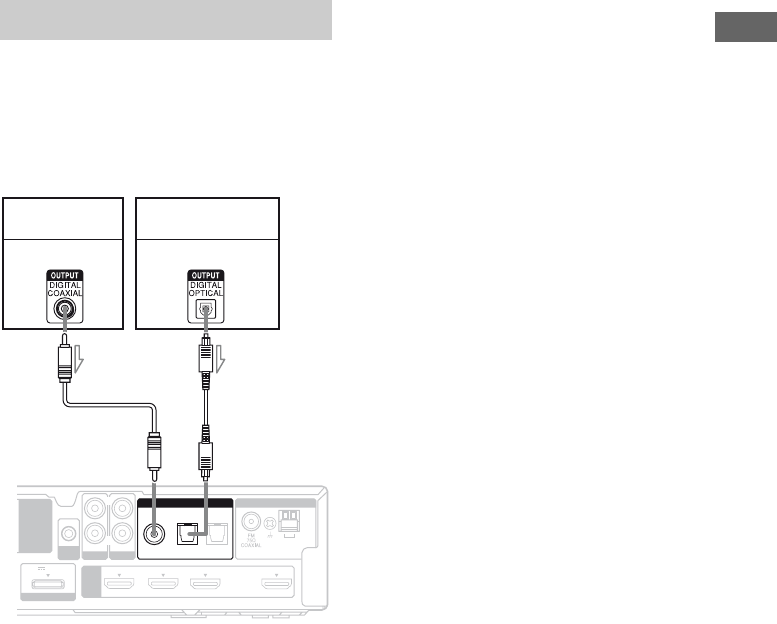
23US
Getting Started
The following illustration shows how to
connect video components such as DVD
player, DVD recorder, etc.
It is not necessary to connect all the cords.
Connect audio and video cords according to
the jacks of your components.
Notes
• If you connect a DVD player/recorder, be sure to
change the initial setting of the VIDEO button on
remote so that you can use the button to control
your DVD player/recorder. For details, see
“Changing the input button assignments” (page
57).
• To input multi channel digital audio from the DVD
player, set the digital audio output setting on the
DVD player. Refer to the operating instructions
supplied with the DVD player.
• When connecting optical digital cords, insert the
plugs straight in until they click into place.
• Do not bend or tie optical digital cords.
• Be sure to connect the video output of the DVD
player and DVD recorder to the TV, so that the
image is displayed on the TV. Refer to the
operating instructions of each connected
component for details.
• You cannot do recording on the DVD recorder via
this receiver. For details, refer to the operating
instructions supplied with the DVD recorder.
Tip
All the digital audio jacks are compatible with
32 kHz, 44.1 kHz, 48 kHz, and 96 kHz sampling
frequencies.
Connecting video components
AM
ANTENNA
AUTO
CAL MIC
HDMI
EZW-T100
DMPORT
DC5V 0.7A MAX
DVD IN BD IN SAT/CATV IN TV OUT
ARC
AUDIO IN
VIDEO
L
R
SA-CD
/
CD
COAX IN
SAT/CATV TV
OPT IN OPT IN
AUDIO IN
TV
DIGITAL
DVD player,
DVD recorder
Audio signal
ACoaxial digital cord (not supplied)
BOptical digital cord (not supplied)
Audio signal
AB
Satellite tuner,
cable television tuner
l : Signal flow
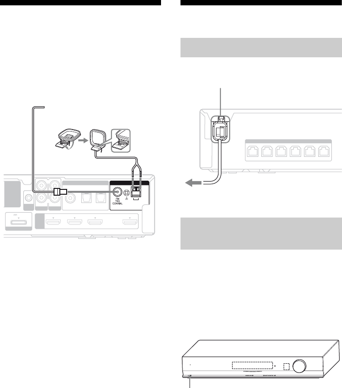
24US
5: Connecting the
antennas
Connect the supplied AM loop antenna and
FM wire antenna.
Before connecting the antennas, be sure to
disconnect the AC power cord.
Notes
• To prevent noise pickup, keep the AM loop
antenna away from the receiver and other
components.
• Be sure to fully extend the FM wire antenna.
• After connecting the FM wire antenna, keep it as
horizontal as possible.
6: Preparing the receiver
Connect the AC power cord to a wall outlet.
Before using the receiver for the first time,
initialize the receiver by performing the
following procedure. This procedure can also
be used to return settings you have made to
their initial settings.
Be sure to use the buttons on the receiver for
this operation.
1Press ?/1 to turn on the
receiver.
2Hold down ?/1 for a few
seconds until “CLEARED”
appears.
All the settings you have changed or
adjusted are reset to the initial settings.
AM
AUTO
CAL MIC
HDMI
EZW-T100
DMPORT
DC5V 0.7A MAX
DVD IN BD IN SAT/CATV IN TV OUT
ARC
AUDIO IN
VIDEO
L
R
SA-CD
/
CD
COAX IN
SAT/CATV TV
OPT IN OPT IN
AUDIO IN
TV
DIGITAL ANTENNA
FM wire antenna (supplied)
AM loop antenna (supplied)
Connecting the AC power cord
Performing initial setup
operations
FRONT R
SPEAKERS
FRONT L SUR R SUR L CENTER
SUBWOOFER
AC power cord
To the wall outlet
MASTER VOLUME
POWER /
ACTIVE STANDBY
?/1

25US
Getting Started
7: Calibrating the
appropriate settings
automatically
(AUTO CALIBRATION)
This receiver is equipped with DCAC (Digital
Cinema Auto Calibration) Technology which
allows you to perform automatic calibration as
follows:
• Check the connection between each speaker
and the receiver.
• Adjust the speaker level.
• Measure the distance of each speaker from
your listening position.
• Measure the frequency characteristics.*
* The measurement result is not utilized for signals
with a sampling frequency of more than 96 kHz.
The DCAC is designed to obtain proper sound
balance in your room. However, you can
adjust the speaker levels manually according
to your preference. For details, see “To adjust
the speaker levels” (page 60).
Before you perform the Auto Calibration, set
up and connect the speakers (page 15, 18).
• The AUTO CAL MIC jack is used for the
supplied optimizer microphone only. Do not
connect other microphones to this jack.
Doing so may damage the receiver and the
microphone.
• During the calibration, the sound that comes
out of the speakers is very loud. The volume
of the sound cannot be adjusted. Pay
attention to the presence of children or to the
effect on your neighborhood.
• Perform the Auto Calibration in a quiet
environment to avoid the effect of noise and
to get a more accurate measurement.
• If there are any obstacles in the path between
the optimizer microphone and the speakers,
the calibration cannot be performed
correctly. Remove any obstacles from the
measurement area to avoid measurement
error.
Notes
• If the muting function has been activated before
you perform Auto Calibration, the muting function
will be set to off automatically.
• When you use the S-AIR product, disconnect the
headphones.
Before you perform Auto
Calibration
continued
26US
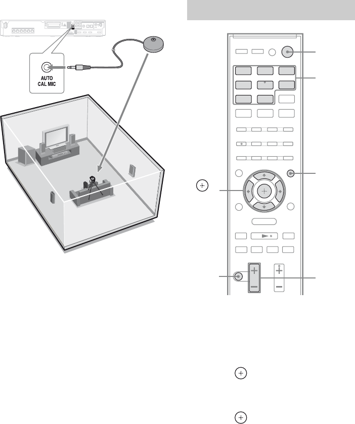
Example: HT-SS370
1Connect the supplied optimizer
microphone to the AUTO CAL
MIC jack.
2Set up the optimizer
microphone.
Place the optimizer microphone at your
listening position.You can also use a stool
or tripod so that the optimizer
microphone remains at the same height as
your ears.
Tip
When you face the speaker towards the optimizer
microphone, you will get a more accurate
measurement.
1Press AMP MENU.
“LEVEL” appears on the display.
2Press V/v repeatedly until
“A.CAL MENU” appears, then
press or b.
3Press V/v repeatedly until
“A.CAL START” appears, then
press .
Measurement starts in a few seconds.
While the time is counting down, stand
away from the measurement area to avoid
measurement error.
The measurement process will take
approximately 30 seconds to complete.
AM
ANTENNA
AUTO
CAL MIC
HDMI
EZW-T100
FRONT R
SPEAKERS
FRONT L SUR R SUR L CENTER
SUBWOOFER
DMPORT
DC5V 0.7A MAX
DVD IN BD IN SAT/CATV IN TV OUT
ARC
AUDIO IN
VIDEO
L
R
SA-CD
/
CD
COAX IN
SAT/CATV TV
OPT IN OPT IN
AUDIO IN
TV
DIGITAL Optimizer
microphone
Performing Auto Calibration
.
mM
>
Xx
BD DVD SAT/
CATV
VIDEO SA-CD/
CD
DMPORT TUNER
O
TV
MENU
Input
buttons
?/1
MASTER
VOL +/–
AMP
MENU
,
V/v/B/b
MUTING
27US
Getting Started
The table below shows the display when
measurement starts.
Notes
• If “CHECK MIC” appears, you cannot perform
the Auto Calibration. Connect the optimizer
microphone, then perform the Auto Calibration
again.
• If “PHONES” appears, you cannot perform the
Auto Calibration. Disconnect the headphones
from the S-AIR product you are using, then
perform the Auto Calibration again.
Tips
• When Auto Calibration starts:
– Stand some distance from the speakers and the
listening position to avoid measurement failure.
This is because test signals are output from the
speakers during measurement.
– Avoid making noise to get a more accurate
measurement.
• The Auto Calibration function will be canceled
when you do the following during the
measurement process:
– Press ?/1 or MUTING.
– Press input buttons on the remote or INPUT
SELECTOR +/– on the receiver.
– Change the volume level.
1Confirm the measurement
result.
When the measurement ends, a beep
sounds and the measurement result
appears on the display.
2Press V/v repeatedly to select
the item, then press .
Note
After “SAVE EXIT” is displayed for 50
seconds, the measurement result is saved
automatically, without the need to save the
procedure.
3Save the measurement result.
Select “SAVE EXIT” in step 2.
The measurement results are saved.
Measurement for Display
Speaker existance TONE
Speaker gain, distance,
frequency response
T. S. P.
Subwoofer gain and
distance
SUBWOOFER
Confirming/saving the
measurement results
Measurement
result
Display Explanation
When the
measurement
process
completes
properly
SAVE
EXIT
Proceed to step
2.
When the
measurement
process fails
ERROR
XXXX
See “When
error codes
appear” (page
28).
Item Explanation
SAVE EXIT Saves the measurement
results and exits the setting
process.
WRN CHECK Displays warning
concerning the
measurement results. See
“When you select “WRN
CHECK”” (page 28).
DIST INFO Displays the measurement
result for speaker distance.
LEVEL INFO Displays the measurement
result for speaker level.
EXIT Exits the setting process
without saving the
measurement results.
continued
28US
When error codes appear
Try the remedies and perform the Auto
Calibration again.
When you select “WRN CHECK”
If a warning on the measurement result is
present, detailed information is displayed.
Press or B to return to step 2 of
“Confirming/saving the
measurement results”.
When you select “DIST INFO” or
“LEVEL INFO”
You can check the speaker distance or speaker
level.
Note
The measurement result of a speaker will not appear
if the receiver does not recognize that the speaker is
connected.
When you have finished
Disconnect the optimizer microphone from the
receiver.
Note
If you have changed the position of the speakers, it
is recommended that you perform Auto Calibration
again in order to enjoy the surround sound.
Error code Cause and remedies
ERROR 32 • The sound received by the
optimizer microphone is out of
the acceptable range.
• The optimizer microphone or
subwoofer may be damaged.
Contact your Sony dealer or local
authorized Sony service facility.
ERROR F 33 The front speakers are not
connected or either the front left or
front right speaker is not
connected.
Check that the front speakers are
connected properly.
ERROR SR33 Either the surround left or
surround right speaker is not
connected.
Check that the surround speakers
are connected properly.
ERROR SW33 The subwoofer is not connected or
it may be damaged.
Contact your Sony dealer or local
authorized Sony service facility.
Warning code Explanation
WARNING 40 The Auto Calibration has
completed. However, the noise
level is high. You may be able to
perform the Auto Calibration
properly if you try it again, even
though the measurement cannot
be performed in all environments.
Try to perform the Auto
Calibration in a quiet
environment.
WARNING 41
WARNING 42
The sound received by the
optimizer microphone is out of
the acceptable range. The
distance between the optimizer
microphone and the speakers is
too close. Set them away, and
then try to perform the Auto
Calibration again.
WARNING 43 The distance and position of the
subwoofer cannot be detected.
This may be caused by noise. Try
to perform the Auto Calibration
in a quiet environment.
NO WARNING There is no warning information.
Warning code Explanation
29US
Playback
You can delete the result of Auto Calibration.
If there is no saved data, you cannot perform
this operation.
1Press AMP MENU.
“LEVEL” appears on the display.
2Press V/v repeatedly until
“A.CAL MENU” appears, then
press or b.
3Press V/v repeatedly until
“A.CAL CLEAR” appears, then
press or b.
4Press V/v repeatedly until
“YES” appears, then press .
The saved result is deleted.
The settings for speaker distance and
speaker level return to their defaults.
Selecting a component
1Press the input button to select
a component.
You can also press INPUT SELECTOR
+/– on the receiver.
The selected input appears on the display.
Clearing the measurement
result Playback
Selected input
[Display]
Components that can
be played back
BD
[BD]
Blu-ray Disc player, etc.,
connected to the BD jack
DVD
[DVD]
DVD player, etc.,
connected to the DVD
jack
SAT/CATV
[SAT/CATV]
Satellite tuner, cable
television tuner, etc.,
connected to the SAT/
CATV jack
.
mM
>
Xx
BD DVD SAT/
CATV
VIDEO SA-CD/
CD
DMPORT TUNER
O
TV
MENU
Input
buttons
MASTER
VOL +/–
MUTING
continued
30US
2Turn on the component and
start playback.
3Press MASTER VOL +/– to
adjust the volume.
You can also use MASTER VOLUME on
the receiver.
To activate the muting function
Press MUTING. “MUTING” lights up and
“MUTING ON” appears on the display for a
few seconds.
The muting function will be canceled when
you do the following.
• Press MUTING again.
• Increase the volume.
• Turn off the receiver.
To avoid damaging your
speakers
Before you turn off the receiver, be sure to turn
down the volume level.
Enjoying sound/images
from the components
connected to the receiver
Selected input
[Display]
Components that can
be played back
TV
[TV]
TV, etc., connected to the
TV jack
VIDEO
[VIDEO]
DVD player, DVD
recorder, etc., connected
to the VIDEO jack
SA-CD/CD
[SA-CD/CD]
Super Audio CD player,
CD player, etc.,
connected to the SA-CD/
CD jack
DMPORT
[DMPORT]
DIGITAL MEDIA PORT
adapter connected to the
DMPORT jack
TUNER
[FM or AM band]
Built-in radio tuner
.
mM
>
Xx
BD DVD SAT/
CATV
VIDEO SA-CD/
CD
DMPORT TUNER
O
TV
MENU
Input
buttons
?/1
SOUND
FIELD +/–
TV VOL
+/–
TV

31US
Playback
1Turn on the TV and choose a
program.
For details, refer to the operating
instructions of the TV.
2Turn on the receiver.
3Press TV.
You can also press INPUT SELECTOR
+/– on the receiver to select “TV”.
4Adjust the volume of the
receiver.
Tips
• When you connect a Sony TV, the audio input of
the TV is switched and the image from the TV
tuner is displayed on the TV screen automatically
by pressing the TV button.
• The sound may be output from the TV’s speaker.
In this case, turn the volume of the TV’s speaker
down to the minimum.
1Turn on the TV.
2Turn on the satellite tuner or
cable television tuner and the
receiver.
3Press SAT/CATV.
You can also press INPUT SELECTOR
+/– on the receiver to select
“SAT/CATV”.
4Change the TV input.
For details, refer to the operating
instructions of the TV.
5Adjust the volume of the
receiver.
Tip
The sound may be output from the TV’s speaker. In
this case, turn the volume of the TV’s speaker down
to the minimum.
Enjoying TV Enjoying a satellite tuner or
cable television tuner

32US
1Turn on the TV.
2Turn on the Blu-ray Disc player
or DVD player, then place the
disc on the tray.
3Turn on the receiver.
4Press DVD or BD.
You can also press INPUT SELECTOR
+/– on the receiver to select “DVD” or
“BD”.
5Change the TV input.
For details, refer to the operating
instructions of the TV.
6Play back the disc.
7Adjust the volume of the
receiver.
Tip
Even if you playback Dolby True HD, Dolby Digital
Plus or DTS-HD with a connected component
compatible with these sound formats, the receiver
accepts as Dolby Digital or DTS. When you connect
the component to the receiver using an HDMI cable
to playback these high-quality sound formats, set the
connected component to output the sound in multi
channel PCM, if possible.
1Turn on the Super Audio CD
player or CD player, then place
the disc on the tray.
2Turn on the receiver.
3Press SA-CD/CD.
You can also press INPUT SELECTOR
+/– on the receiver to select “SA-CD/
CD”.
4Adjust the volume of the
receiver.
1Turn on the receiver.
2Press DMPORT.
You can also press INPUT SELECTOR
+/– on the receiver to select “DMPORT”.
3Start playback of the connected
component.
Tip
When listening to MP3 or other compressed music
files using a portable audio source, you can enhance
the sound. Press SOUND FIELD +/– repeatedly
until “P. AUDIO” appears on the display.
Enjoying Blu-ray Disc/DVD Enjoying a Super Audio CD/CD
Enjoying a connected
component through DMPORT
connection
33US
Enjoying Surround Sound
Selecting the sound field
This receiver can create multi channel
surround sound. You can select one of the
optimized sound fields from the system’s
preprogrammed sound fields.
.
Press SOUND FIELD +/– repeatedly
to select the sound field you want.
You can also press SOUND FIELD on the
receiver.
Types of sound field available
a)D.C.S. technology is used. For details, see “Glossary” (page 63).
b)This decoding mode appears when you connect the headphones to surround amplifier (S-AIR sub unit) (not
supplied).
Enjoying Surround Sound
.>
Xx
SOUND
FIELD +/–
Sound field
for
Sound field
[Display]
Effect
A.F.D. 2CH STEREO
[2CH STEREO]
When multi channel surround formats are input, the signals are
downmixed to 2 channel.
A.F.D. STANDARD
[A.F.D. STD]
Presents the sound as it was recorded/encoded without adding
any surround effects. However, this receiver will generate a
low frequency signal for output to the subwoofer when there
is no LFE signals.
A.F.D. MULTI
[A.F.D. MULTI]
Reproduces sound from any of the format to 2 or more
speakers.
PRO LOGIC
[PRO LOGIC]
Performs Dolby Pro Logic decoding. The source recorded in 2
channel format is decoded into 4.1 channels.
PRO LOGIC II MOVIE
[PLII MOVIE]
Performs Dolby Pro Logic II Movie mode decoding. This
setting is ideal for movies encoded in Dolby Surround. In
addition, this mode can reproduce sound in 5.1 channel for
watching videos of overdubbed or old movies.
PRO LOGIC II MUSIC
[PLII MUSIC]
Performs Dolby Pro Logic II Music mode decoding. This
setting is ideal for normal stereo sources such as CDs.
Movie MOVIE-D.C.S.-a)
[MOVIE-D.C.S.-]
Reproduces the sound characteristics of the Sony Pictures
Entertainment “Cary Grant Theater” cinema production
studio. This is a standard mode, great for watching almost any
type of movie.
Music SPORTS [SPORTS] Reproduces the feeling of sports broadcasting.
GAME [GAME] Reproduces powerful and realistic sound, suited for playing
video games.
NEWS [NEWS] Reproduces a clearer announcer’s voice.
PORTABLE AUDIO
ENHANCER [P. AUDIO]
Reproduces a clear enhanced sound image from your portable
audio device. This mode is ideal for MP3 and other
compressed music.
Othersb) HEADPHONE 2CH
[HP 2CH]
Outputs the sound from headphone left and right. Multi
channel surround formats are downmixed to 2 channels.
HEADPHONE THEATER
[HP THEATER]
Outputs the sound as surround from headphone left and right.
continued
34US
Notes
• The effects provided by the virtual speakers may
cause increased noise in the playback signal.
• When listening with sound fields that employ the
virtual speakers, you will not be able to hear any
sound coming directly from the surround speakers.
• Multi channel Linear PCM is not available for
“P. AUDIO”.
• The movie and music mode do not work when:
– signals with a sampling frequency of more than
48 kHz is input.
– the multi channel Linear PCM signals are
received via an HDMI IN jack.
• The sound is not output from multiple speakers
depending on the source.
• Depending on the disc or source, the beginning of
the sound may be cut off as the optimum mode is
automatically selected. To avoid cutting the sound,
select “A.F.D. STD”.
• When the input signal is multi channel source,
Dolby Pro Logic II MOVIE/MUSIC are canceled
and the multi channel source is output directly.
• When the bilingual broadcast sound is input, Dolby
Pro Logic II MOVIE/MUSIC are not effective.
• Depending on the input stream, the decoding mode
may not be effective.
• When you select “MOVIE-D.C.S.-” depending on
the input stream, Dolby Pro Logic may be applied
automatically.
• When changing the sound mode while using the
S-AIR receiver (not supplied), sound from the
S-AIR receiver (not supplied) may skip.
Tip
You can identify the encoding format of DVD
software, etc., by looking at the logo on the package.
Enjoying the sound at low
volume
(NIGHT MODE)
You can enjoy sound effects and hear the
dialog clearly even at a low volume level using
this function. This function is useful for
enjoying sound at night.
1Press AMP MENU.
“LEVEL” appears on the display.
2Press V/v repeatedly until
“AUDIO” appears, then press
or b.
3Press V/v repeatedly until
“NIGHT MODE” appears, then
press or b.
4Press V/v repeatedly until
“NIGHT ON” appears, then
press .
“NIGHT” lights up on the display.
• NIGHT ON: Turn on the NIGHT
MODE.
• NIGHT OFF: Turn off the NIGHT
MODE.
The initial setting is “NIGHT OFF”.
5Press AMP MENU.
The AMP menu turns off.
O
MENU
AMP
MENU
,
V/v/B/b
35US
Tuner Operations
Listening to FM/AM radio
You can listen to FM and AM broadcasts
through the built-in tuner. Before operation, be
sure you have connected the FM and AM
antennas to the receiver (page 24).
1Press TUNER repeatedly to
select the FM or AM band.
You can also press INPUT SELECTOR
+/– on the receiver.
2Press and hold TUNING +/–
until the auto scanning starts.
Press TUNING + to scan from low to
high frequency; press TUNING – to scan
from high to low frequency.
The receiver stops scanning whenever a
station is received. To stop the Auto
Tuning manually, press TUNING +/–.
If an FM program is noisy
If an FM program is noisy, you can select
monaural reception. There will be no stereo
effect, but reception will improve.
1Press MENU/HOME.
2Press V/v repeatedly until “FM
MODE” appears, then press
or b.
3Press V/v repeatedly until
“MONO” appears, then press
.
• STEREO: Stereo reception.
• MONO: Monaural reception.
The initial setting is “STEREO”.
4Press MENU/HOME.
Tip
To improve reception, reorient the supplied
antennas.
Tuner Operations
.
mM
>
Xx
BD DVD SAT/
CATV
VIDEO SA-CD/
CD
DMPORT TUNER
O
TV
MENU
TUNING
+/–
TUNER
MENU/
HOME
,
V/v/B/b
ENTER
D. TUNING
Numeric
buttons
SHIFT
Tuning into a station
automatically (Auto Tuning)

36US
Enter the frequency of a station directly by
using the numeric buttons.
1Press TUNER repeatedly to
select the FM or AM band.
You can also press INPUT SELECTOR
+/– on the receiver.
2Press D.TUNING.
3Press and hold SHIFT, then
press the numeric buttons to
enter the frequency.
Example 1: FM 102.50 MHz
Select 1 b 0 b 2 b 5
Example 2: AM 1,350 kHz
Select 1 b 3 b 5 b 0
If you have tuned in an AM station, adjust
the direction of the AM loop antenna for
optimum reception.
4Press and hold SHIFT, then
press ENTER.
If a wrong frequency is entered
“FM ---.--” or “AM ----” appears and then the
display returns to the current frequency.
If you cannot tune in a station
Make sure you have entered the right
frequency. If not, repeat steps 2 to 4. If you
still cannot tune in a station, the frequency is
not used in your area.
The AM tuning interval can be set to either
10 kHz or 9 kHz.
1Press TUNER repeatedly until
“AM” appears on the display.
2Press MENU/HOME.
3Press V/v repeatedly until “AM
STEP” appears on the display,
then press or b.
“10K t 9K” or “9K t 10K” appears on
the display.
4Press .
“COMPLETE” appears on the display.
The AM tuning interval is changed.
5Press MENU/HOME.
Note
If you change the interval, AM preset stations will
be erased.
Tuning into a station directly
(Direct Tuning)
Changing the AM tuning interval
37US
Tuner Operations
Presetting radio stations
You can preset up to 20 FM stations and 10
AM stations. Then you can easily tune in the
stations you often listen to.
1Press TUNER repeatedly to
select the FM or AM band.
You can also press INPUT SELECTOR
+/– on the receiver.
2Press and hold TUNING +/–
until the auto scanning starts.
Scanning stops when the receiver tunes in
a station. “ST” (for stereo program) lights
up on the display.
3Press MEMORY.
A preset number appears on the display.
4Press V/v repeatedly to select
the preset number you want.
You can also select the preset number
directly by holding SHIFT and then press
the numeric buttons.
5Press .
“COMPLETE” appears on the display
and the station is stored.
6Repeat steps 2 to 5 to store
other stations.
To change the preset number
Restart from step 3.
1Press TUNER repeatedly to
select the FM or AM band.
You can also press INPUT SELECTOR
+/– on the receiver.
2Press PRESET +/– repeatedly
to select the preset station you
want.
Each time you press the button, the
receiver tunes in one preset station.
You can also press and hold SHIFT, then
press the numeric buttons to select the
preset station you want. Then, press to
enter the selection.
.
mM
>
Xx
BD DVD SAT/
CATV
VIDEO SA-CD/
CD
DMPORT TUNER
O
TV
MENU
TUNING
+/–
Numeric
buttons
MENU/
HOME
TUNER
,
V/v/B/b
PRESET
+/–
DISPLAY
MEMORY
Tuning to preset stations

38US
You can enter a name for preset stations.
These names (for example, “XYZ”) appear on
the display when a station is selected.
Note that no more than one name can be
entered for each preset station.
1Press TUNER repeatedly to
select the FM or AM band.
You can also press INPUT SELECTOR
+/– on the receiver.
2Press PRESET +/– repeatedly
to select the preset station you
want to create an index name
for.
3Press MENU/HOME.
4Press V/v repeatedly until
“NAME IN” appears, then press
.
5Create a name by using
V/v/B/b.
Press V/v repeatedly to select a character,
then press b to move the cursor to the
next position. Letters, numbers and other
symbols can be input for a radio station
name.
If you enter a wrong character
Press B/b repeatedly until the character to
be changed flashes, then press V/v
repeatedly to select the desired character.
6Press .
“COMPLETE” appears on the display
and the station name is stored.
7Press MENU/HOME.
When the receiver is set to “FM” or “AM”,
you can check the frequency using the display.
Press DISPLAY.
Each time you press DISPLAY, the display
changes as shown.
Station namea) t Frequencyb) t
FM Modeb)
a)This is displayed if you have entered a name for a
preset station.
b)Returns to the original display when several
seconds have elapsed.
Naming preset station Viewing the station name or
frequency on the display

39US
“BRAVIA” Sync Features
What is “BRAVIA” Sync?
“BRAVIA” Sync is compatible with Sony TV,
Blu-ray Disc/DVD player, AV amplifier, etc.,
that is equipped with the Control for HDMI
function.
By connecting Sony components that are
compatible with the “BRAVIA” Sync using an
HDMI cable (not supplied), operation is
simplified as follows:
• One-Touch Play (page 41)
• System Audio Control (page 41)
• System Power Off (page 43)
• Audio Return Channel (ARC) (page 45)
• Theater Mode (page 46)
Control for HDMI is a mutual control function
standard used by HDMI CEC (Consumer
Electronics Control) for HDMI (High-
Definition Multimedia Interface).
The Control for HDMI function
will not operate correctly in the
following cases:
• When you connect the receiver to a
component which does not correspond with
Sony Control for HDMI function.
• When you connect the receiver and
components using other than HDMI
connection.
We recommend that you connect the receiver
to products featuring “BRAVIA” Sync.
Note
Depending on the connected component, the
Control for HDMI function may not work. Refer to
the operating instructions of the component.
Preparing for the
“BRAVIA” Sync
To use the “BRAVIA” Sync, turn the Control
for HDMI function on for both the receiver
and the connected component. The receiver is
compatible with the “Control for HDMI-Easy
Setting” function.
When your TV is compatible
with the “Control for HDMI-Easy
Setting” function
When you connect a Sony TV with the
“Control for HDMI-Easy Setting” function,
the Control for HDMI function of the receiver
can be turned on simultaneously by turning the
Control for HDMI function of the TV on.
1Make sure that the receiver, TV, and
playback components are connected
using an HDMI cable (not supplied).
(The respective components must be
compatible with the Control for HDMI
function).
2Turn on the receiver, TV and the
playback components.
3Turn the Control for HDMI function of
the TV on.
The Control for HDMI function of the
receiver and all the connected components
are simultaneously turned on. When the
setup is completed, “COMPLETE” will
appear. Wait until the setup is complete.
For details on setup of the TV, refer to the
operating instructions of your TV.
“BRAVIA” Sync Features
continued
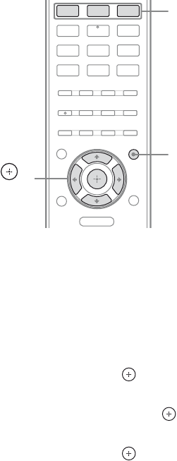
40US
When your TV is not compatible
with the “Control for HDMI-Easy
Setting” function
Turn the Control for HDMI function of the
receiver and the connected component on
individually.
1Perform the steps given in “When your
TV is compatible with the “Control for
HDMI-Easy Setting” function” (page
39).
2Press AMP MENU.
“LEVEL” appears on the display.
3Press V/v repeatedly until “SET HDMI”
appears, then press or b.
4Press V/v repeatedly until “CTRL
HDMI” appears, then press or b.
5Press V/v repeatedly until “CTRL ON”
appears, then press .
The Control for HDMI function is set to on.
6Press one of the input buttons (BD,
DVD, SAT/CATV) to display the image
of the playback component for which
you want to set the Control for HDMI
function.
7Turn the Control for HDMI function of
the connected component on.
For details, refer to the operating
instructions of the connected component.
8Repeat step 6 and 7 to set the Control
for HDMI function for other connected
component.
Notes
• When you unplug the HDMI cable or change the
connection, perform the steps given in “When your
TV is compatible with the “Control for HDMI-
Easy Setting” function” (page 39) or “When your
TV is not compatible with the “Control for HDMI-
Easy Setting” function” (page 40).
• You cannot perform One-Touch Play and System
Audio Control during Control for HDMI-Easy
Setting operation.
• Before you do the Control for HDMI-Easy Setting
from the TV, be sure to turn on the TV, connected
components and receiver.
• If the playback components cannot function after
you have made the settings for Control for HDMI-
Easy Setting, check the Control for HDMI setting
on your TV.
• If the connected components do not support
Control for HDMI-Easy Setting, you need to set
the Control for HDMI function for the connected
components to on before you perform the Control
for HDMI-Easy Setting from the TV.
BD DVD SAT/
CATV
VIDEO SA-CD/
CD
DMPORT TUNER
O
TV
MENU
AMP
MENU
,
V/v/B/b
Input
buttons

41US
“BRAVIA” Sync Features
Playing back components
with one-touch operation
(One-Touch Play)
By a simple operation (one touch),
components connected to the receiver with
HDMI connections start playback
automatically.
You can enjoy the sound/image using the
connected components.
Play back a connected component.
The receiver and the TV are turned on
automatically and switched to the appropriate
HDMI input.
Note
Be sure that the System Audio Control setting is set
to on using TV menu.
Watching a DVD/Blu-ray Disc by
simple operation
You can also select a connected component,
such as a DVD/Blu-ray Disc player using the
TV menu. In this case, the receiver and the TV
switch to the appropriate HDMI input.
Note
Depending on the TV, the start of the content may
not be output.
Tip
You can enjoy the components that are connected to
the HDMI jacks, even if you turn the receiver off.
The POWER/ACTIVE STANDBY indicator lights
up in amber.
Enjoying the TV sound
from the speakers
connected to the receiver
(System Audio Control)
You can enjoy the TV sound from the speakers
connected to the receiver by a simple
operation.
You can operate System Audio Control
function using the TV menu. For details, refer
to the operating instructions of the TV.
When System Audio Control function is
turned on, the receiver will turns on and
switches to the appropriate input
automatically.
TV sound is output from the speakers
connected to the receiver, and the volume of
the TV is minimized simultaneously.
You can use the System Audio Control
function as follows.
• If you turn on the receiver while the TV is
turned on, the System Audio Control
function will automatically be set to on and
the TV sound will output from the speakers
connected to the receiver. However, if you
turn off the receiver, the sound will output
from the TV speakers.
• You can adjust the receiver’s volume when
you adjust the TV volume.
Notes
• If System Audio Control does not function
according to your TV setting, refer to the operating
instructions of the TV.
• When you connect a TV that does not have System
Audio Control function, the System Audio Control
function does not work.
• If the TV is turned on before turning on the
receiver, the TV sound will not be output for a
moment.
42US
When the System Audio Control function is
active, and the output method changes from
the TV speaker to the speakers connected to
the receiver automatically, loud sound may be
output depending on the volume level of the
receiver. You can prevent this by limiting the
maximum volume level.
1Press AMP MENU.
“LEVEL” appears on the display.
2Press V/v repeatedly until “SET
HDMI” appears, then press
or b.
3Press V/v repeatedly until “VOL
LIMIT” appears, then press
or b.
4Press V/v repeatedly to select
the maximum volume level you
want, then press .
The maximum volume level changes as
follows:
LIMIT MAX y LIMIT 49 y LIMIT
48 y ...... y LIMIT 2 y LIMIT 1
y LIMIT MIN
5Press AMP MENU.
The AMP menu turns off.
Notes
• This function is available only when the Control
for HDMI function is set to on.
• This function is not available when the output
method changes from the speakers connected to the
receiver to the TV speaker.
Tips
• Sony recommends that you set the maximum
volume level to a little lower than the volume you
usually listen to.
• Regardless of the maximum volume level you set,
the MASTER VOLUME on the receiver and the
MASTER VOL +/– on the remote are operable.
• If you do not want to limit the maximum volume
level, select “LIMIT MAX”.
Using the Volume Limit function
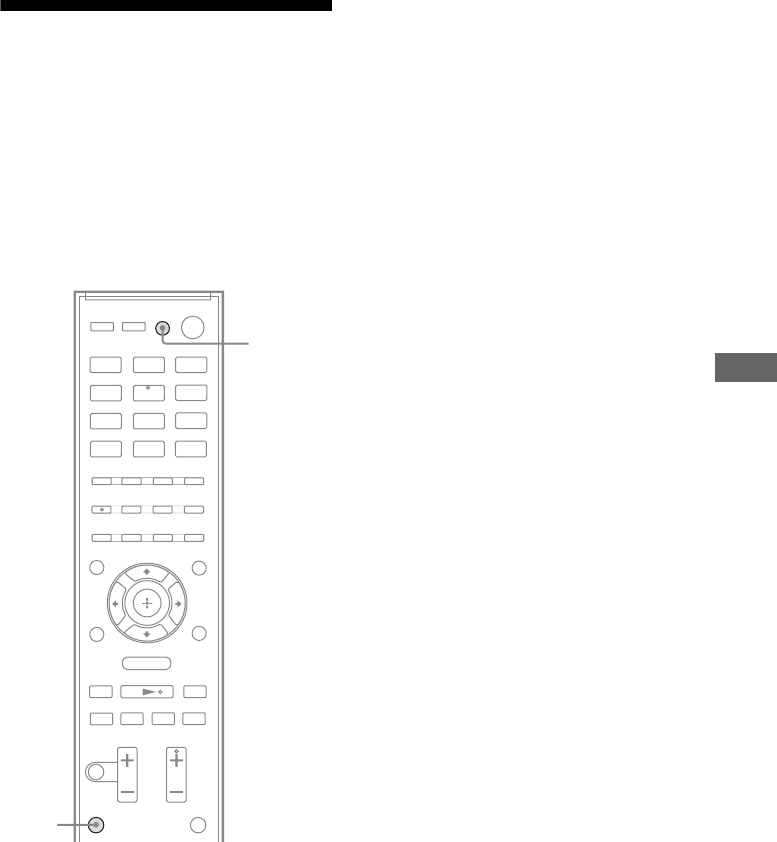
43US
“BRAVIA” Sync Features
Turning off the receiver
with the TV
(System Power Off)
When you turn the TV off by using the
POWER button on the TV’s remote, the
receiver and the connected components turn
off automatically.
You can also use the receiver’s remote to turn
off the TV.
Press TV and TV ?/1 at the same
time.
The TV, receiver and the components
connected via HDMI are turned off.
Notes
• Set the TV Standby Synchro to “ON” before using
the System Power Off function. For details, refer to
the operating instructions of the TV.
• Depending on the status, the connected
components may not be turned off. For details,
refer to the operating instructions of the connected
components.
.
mM
>
Xx
BD DVD SAT/
CATV
VIDEO SA-CD/
CD
DMPORT TUNER
O
TV
MENU
TV
TV ?/1
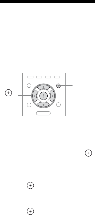
44US
Using the power saving
function
(HDMI Pass Through)
If a “BRAVIA” Sync-compatible TV is
connected to the receiver, and the TV is turned
off, HDMI signal transmission stops, and
power consumption is reduced.
1Press AMP MENU.
“LEVEL” appears on the display.
2Press V/v repeatedly until “SET
HDMI” appears, then press
or b.
3Press V/v repeatedly until
“PASS THRU” appears, then
press or b.
4Press V/v repeatedly until the
setting you want appears, then
press .
• THRU AUTO: When the TV is turned
on while the receiver is in the standby
mode, the receiver outputs HDMI
signals from the receiver’s HDMI TV
OUT jack. Sony recommends this
setting if you use a TV that is
compatible with “BRAVIA” Sync. This
setting saves power in the standby mode
compared with the “THRU ON” setting.
• THRU ON: When the receiver is in the
standby mode, the receiver continuously
outputs HDMI signals from the
receiver’s HDMI TV OUT jack.
5Press AMP MENU.
The AMP menu turns off.
Notes
• The power saving function may not work for some
TVs compatible with the “BRAVIA” Sync. In this
case, set “PASS THRU” to “THRU ON”.
• Depending on your components, it may take time
before image or sound is output.
• This function is available only when the Control
for HDMI function is set to on.
O
MENU
AMP
MENU
,
V/v/B/b
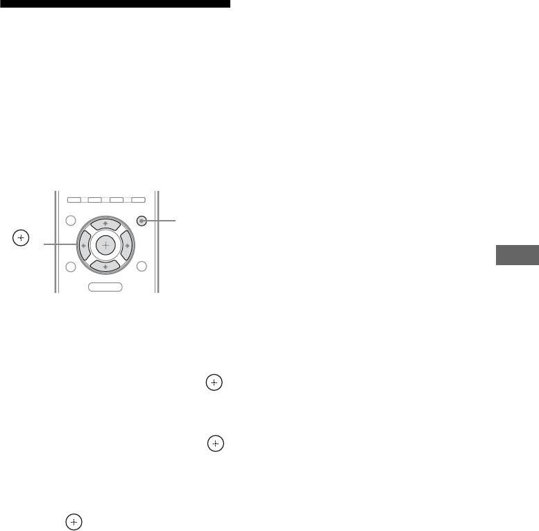
45US
“BRAVIA” Sync Features
Enjoying the TV sound via
an HDMI connection
(Audio Return Channel)
The receiver can receive the audio signal of the
TV via an HDMI cable when your TV is
compatible with the Audio Return Channel
(ARC) function. You can enjoy TV sound via
the receiver by using just one HDMI cable.
1Press AMP MENU.
“LEVEL” appears on the display.
2Press V/v repeatedly until “SET
HDMI” appears, then press
or b.
3Press V/v repeatedly until
“ARC” appears, then press
or b.
4Press V/v repeatedly until the
setting you want appears, then
press .
• ARC ON: The receiver receives the
audio signal of the TV automatically via
an HDMI cable.
• ARC OFF: The receiver receives the
audio signal of the TV via audio or
optical digital cord.
5Press AMP MENU.
The AMP menu turns off.
Notes
• This function is available only when the Control
for HDMI function is set to on.
• Be sure that your TV is compatible with Audio
Return Channel (ARC) function. For details on the
TV settings, refer to the operating instructions of
the TV.
O
MENU
AMP
MENU
,
V/v/B/b

46US
Enjoying optimum sound
field for the selected
scene
(Scene Select)
The Scene Select function allows you to enjoy
the optimum picture quality and switches the
sound field according to the selected scene on
your TV. For details on the operation, refer to
the operating instructions of the TV.
Notes
• This function is available only when the Control
for HDMI function is set to on.
• The sound field may not switch depending on the
TV.
Enjoying movies with the
optimum sound field
(Theater Mode)
Press the THEATER button on the
remote of the receiver, TV, or the
Blu-ray Disc player, while pointing
the remote toward the TV.
The sound field switches to “MOVIE-D.C.S.-”.
To return to the previous sound field, press the
THEATER button again.
Note
The sound field may not switch depending on the
TV.
Tip
The sound field may be changed back to the
previous one when you change the TV’s input.
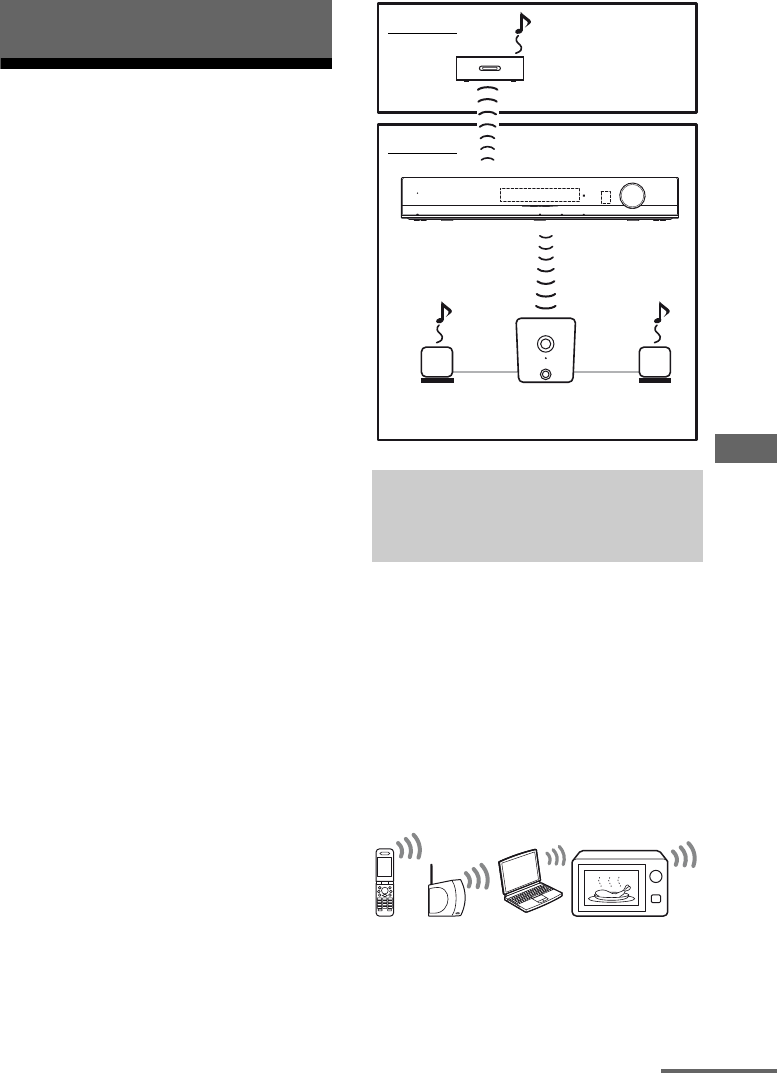
47US
S-AIR Operations
About S-AIR products
This receiver is compatible with the S-AIR
function (page 64), which allows wireless
sound transmission between S-AIR products.
When you purchase the S-AIR product, you
need to establish the sound transmission.
There are two types of S-AIR product.
• S-AIR main unit (this receiver):
This is for transmitting sound.
You can use up to 3 S-AIR main units. (The
number of usable S-AIR main unit depends
on the use environment.)
• S-AIR sub unit (not supplied): This is for
receiving sound.
– Surround amplifier: You can enjoy
surround speaker sound wirelessly.
– S-AIR receiver: You can enjoy system’s
sound in another room.
These S-AIR products can be purchased as an
option (the S-AIR products lineup differs
depending on the area).
Notes or instruction for the S-AIR sub unit in
this operating instructions is refer only when
the S-AIR sub unit is used.
S-AIR products use a radio frequency of
2.4 GHz. Certain electronic equipment or
other factors may cause lost connection or
instability in S-AIR reception.
• Electronic equipment influence
The following may cause interference or
cross talk.
– Cellular phones, cordless phones
– Wireless LAN, personal computers
– Game machines using radio signals
– Microwave ovens
S-AIR Operations
About environments where
S-AIR products (S-AIR main unit
and sub unit) are used
MASTER VOLUME
ACTIVE STANDBY
POWER/
S-AIR sub unit
(S-AIR receiver)
S-AIR main unit
(this receiver)
S-AIR sub unit
(surround amplifier)
Room B
Room A
continued

48US
• Other factors
The following may cause poor reception.
– Materials or structures, such as walls and
floors
– The location where an S-AIR product is
placed
When using S-AIR products, place them as far
as possible from the above electronic
equipment, or place where S-AIR reception is
stable.
Setting up an S-AIR
product
Before using an S-AIR product, be sure to
perform the following settings to establish the
sound transmission.
To make use of the S-AIR function, you need
to insert the wireless transmitter (not supplied)
into the S-AIR main unit and the wireless
transceiver (not supplied) into the S-AIR sub
unit.
Notes
• Before inserting the wireless transmitter/
transceiver, be sure to disconnect the AC power
cord.
• Do not insert/detach the wireless transmitter/
transceiver (not supplied) while the receiver is
turned on.
• Do not touch the terminals of the wireless
transmitter/transceiver.
Inserting the wireless
transmitter/transceiver
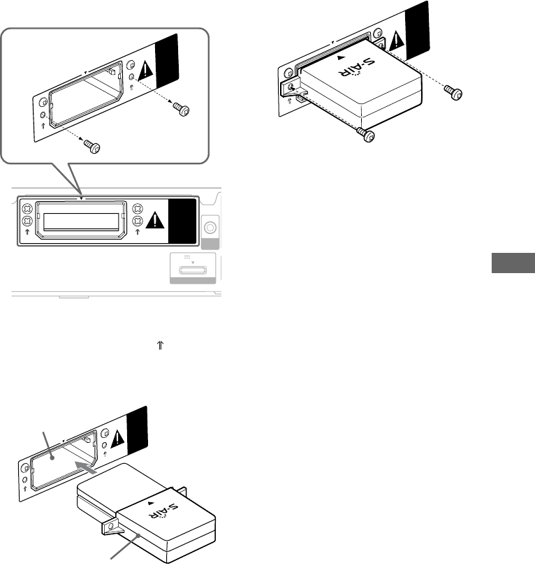
49US
S-AIR Operations
To insert the wireless
transmitter into the S-AIR main
unit
1Remove the screws.
Note
Remove the screws pointed with marks. Do
not remove other screws.
2Insert the wireless transmitter.
Notes
• Insert the wireless transmitter with the S-AIR
logo facing up.
• Insert the wireless transmitter so that the V
marks are aligned.
• Do not insert other than the wireless
transmitter into the EZW-T100 slot.
3Use the screws that you removed from
step 1 to fasten the wireless
transmitter.
Note
Do not use other screws to fasten the wireless
transmitter.
To insert the wireless
transceiver into the S-AIR sub
unit
Refer to the operating instructions of the
S-AIR sub unit.
AUTO
CAL MIC
EZW-T100
DMPORT
DC5V 0.7A MAX
EZW-T100
EZW-T100
Wireless transmitter
EZW-T100 slot
EZW-T100
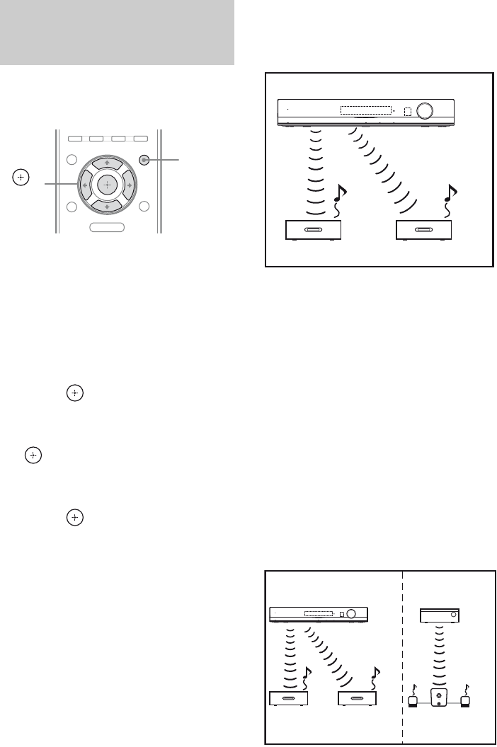
50US
When you match the ID of the S-AIR main
unit and the S-AIR sub unit, you can establish
sound transmission.
To set the ID of the S-AIR main
unit
1Press AMP MENU.
“LEVEL” appears on the display.
2Press V/v repeatedly until
“S-AIR SET” appears, then
press or b.
3Press V/v repeatedly until
“S-AIR ID” appears, then press
or b.
4Press V/v repeatedly to select
the desired ID (A, B or C) then
press .
5Set the S-AIR sub unit to the
same ID.
Sound transmission is established as
follows:
6Press AMP MENU.
The AMP menu turns off.
To set the ID of the S-AIR sub
unit
Be sure to match the ID on S-AIR sub unit you
want to the S-AIR main unit.
For details on setting the ID of the S-AIR sub
unit, refer to the operating instructions
supplied with the S-AIR sub unit.
To use multiple S-AIR main
units
You can use multiple S-AIR products by
setting a different ID for each unit.
Sound transmission is established as follows:
Establishing sound transmission
between the S-AIR main unit and
S-AIR sub unit (ID setting)
O
MENU
AMP
MENU
,
V/v/B/b
ID A ID A
ID A
MASTER VOLUME
ACTIVE STANDBY
POWER/
S-AIR main unit (this receiver)
S-AIR sub unit S-AIR sub unit
ID A ID A ID B
ID A ID B
MASTER VOLUME
ACTIVE STANDBY
POWER/
S-AIR main unit
(this receiver)
Other S-AIR
main unit
S-AIR
sub unit
S-AIR
sub unit
S-AIR sub unit
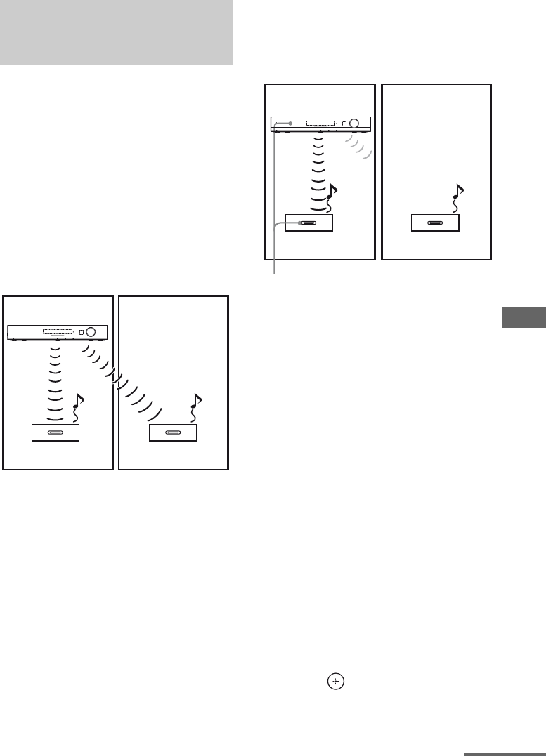
51US
S-AIR Operations
To establish sound transmission, you need to
set the same ID for your S-AIR main unit and
S-AIR sub unit. However, if your neighbors
have S-AIR products and their IDs are the
same as yours, your neighbors could receive
the sound of your S-AIR main unit or vice
versa.
To prevent this, you can pair the S-AIR main
unit with a specific S-AIR sub unit by
performing the pairing operation.
xBefore pairing
Sound transmission is established by the ID.
xAfter pairing
Sound transmission is established between the
paired S-AIR main unit and S-AIR sub unit(s)
only.
To perform pairing
1Place the S-AIR sub unit that
you want to pair near the S-AIR
main unit.
Note
Remove headphones from the surround
amplifier (if connected).
2Match the IDs of the S-AIR main
unit and the S-AIR sub unit.
• To set the ID of the S-AIR main unit,
see “To set the ID of the S-AIR sub
unit” (page 50).
• To set the ID of the S-AIR sub unit,
refer to the operating instructions
supplied with the S-AIR sub unit.
3Press AMP MENU.
“LEVEL” appears on the display.
4Press V/v repeatedly until
“S-AIR SET” appears, then
press or b.
Pairing the S-AIR main unit with
a specific S-AIR sub unit
(Pairing operation)
ID A
ID A
ID A
MASTER VOLUME
ACTIVE STANDBY
POWER/
Your room
S-AIR main unit
(this receiver)
S-AIR sub unit S-AIR sub unit
Neighbor
ID A
ID A
ID A
MASTER VOLUME
ACTIVE STANDBY
POWER/
Your room
S-AIR main unit
(this receiver)
S-AIR sub unit S-AIR sub unit
Neighbor
No transmission
Pairing
continued
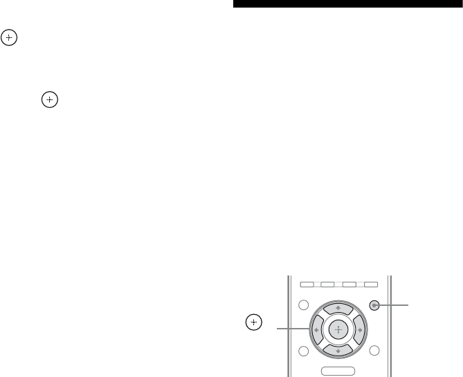
52US
5Press V/v repeatedly until
“PAIRING” appears, then press
or b.
6Press V/v repeatedly until the
setting you want appears, then
press .
• START: The S-AIR main unit starts
pairing.
• CONDITION: You can check the
current ID. When the pairing setting is
timed out, “NO PAIRING” appears on
the display.
7Start pairing of the S-AIR sub
unit.
xFor the surround amplifier
Refer to the operating instructions
supplied with surround amplifier.
xFor the S-AIR receiver
Refer to the operating instructions
supplied with S-AIR receiver.
8Pairing completed.
“COMPLETE” appears on the display.
9Press AMP MENU.
The AMP menu turns off.
Note
Perform the pairing within several minutes after you
select “START” in step 6. Otherwise, the pairing is
canceled automatically and “INCOMPLETE”
appears on the display.
To cancel pairing
Reset the ID of the S-AIR main unit. For
details, see “To set the ID of the S-AIR sub
unit” (page 50). You can set the same ID as
before.
Enjoying the system’s
sound in another room
(For the S-AIR receiver only (not
supplied))
You can enjoy the system’s sound in another
room by using the S-AIR receiver. The S-AIR
receiver can be placed in another room for
enjoying the system’s sound there.
For details of the S-AIR receiver, refer to the
operating instructions supplied with S-AIR
receiver.
Note
Sources with copyright protection may not be
playable on S-AIR products.
1Set the ID of the S-AIR receiver
to match the S-AIR main unit.
• To set the ID of the S-AIR main unit,
see “To set the ID of the S-AIR sub
unit” (page 50).
• To set the ID of the S-AIR receiver,
refer to the operating instructions
supplied with S-AIR receiver.
Notes
• When you are using another S-AIR sub unit,
such as a surround amplifier, do not change
the ID of the S-AIR main unit. Set the ID of
the S-AIR receiver to match the ID of the
S-AIR main unit.
• When you pair the S-AIR main unit and
another S-AIR sub unit, such as a surround
amplifier, you also need to pair the S-AIR
main unit and the S-AIR receiver. For details,
see “Pairing the S-AIR main unit with a
specific S-AIR sub unit (Pairing operation)”
(page 51).
O
MENU
AMP
MENU
,
V/v/B/b

53US
S-AIR Operations
2Press AMP MENU.
“LEVEL” appears on the display.
3Press V/v repeatedly until
“S-AIR SET” appears, then
press or b.
4Press V/v repeatedly until
“S-AIR MODE” appears, then
press or b.
5Press V/v repeatedly until the
setting you want appears, then
press .
• PARTY: The S-AIR sub unit outputs
sound according to function set on the
S-AIR main unit.
• SEPARATE: You can select the input
you want for the S-AIR receiver while
the input of the S-AIR main unit remain
unchanged.
When “SEPARATE” is set, the
functions you can select are “MAIN
UNIT”, “SA-CD/CD”, “DMPORT”,
“TUNER FM” and “TUNER AM”. To
enjoy the same function as the S-AIR
main unit, select “MAIN UNIT”.
6Select the desired function on
the S-AIR product.
When the sound is other than 2 channel
stereo, multi channel sound is
downmixed to 2 channel.
7Adjust the volume on the S-AIR
receiver.
Note
When “TUNER FM” or “TUNER AM” is selected
on the receiver, you can only select the same band
for the tuner on the S-AIR product.
To control the system from the
S-AIR receiver
You can control the system from the S-AIR
receiver by using the following buttons.
For details, refer to the operating instructions
of the S-AIR receiver.
Press Operation
N, X, x,
./>Share the same operations on the
remote.
S-AIR CH Change the function of the
system.
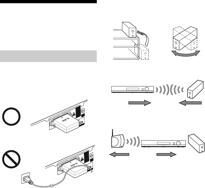
54US
Stabilizing S-AIR
reception
Read the following when S-AIR reception is
poor or unstable.
Check the following.
• Keep cords that are connected to the S-AIR
product (AC power cord, speaker cords, or
other cords) away from the wireless adapter
and slot.
• Keep as much space as possible around
S-AIR products.
– Avoid placing S-AIR products on top of or
directly below other electronic equipment.
– Avoid placing S-AIR products in a closed
rack, metal rack or under a table.
• Adjust the location (height, orientation, and
place in the room) of S-AIR products until
reception is the most stable.
– Place so that the wireless adapters of the
S-AIR main unit and sub unit are closer.
– Place so that S-AIR products are separated
from other wireless devices.
– Place so that S-AIR products are separated
from metal doors or tables.
If you still cannot improve S-AIR reception,
change the “RF CHANGE” setting (page
55).
When S-AIR reception is poor
AUTO
CAL MIC
DMPORT
DC5V 0.7A MAX
DMPORT
DC5V 0.7A MAX
EZW-T100
EZW-T100
AUTO
CAL MIC
MASTER VOLUME
ACTIVE STANDBY
POWER/
MASTER VOLUME
ACTIVE STANDBY
POWER/
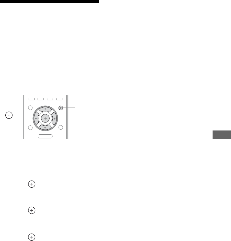
55US
S-AIR Operations
Changing the channel for
better sound
transmission
If you use multiple wireless systems which
sharing the 2.4 GHz band, such as wireless
LAN or Bluetooth, the transmission of S-AIR
products or other wireless systems may be
unstable. In this case, the transmission may be
improved by changing the following “RF
CHANGE” setting.
1Press AMP MENU.
“LEVEL” appears on the display.
2Press V/v repeatedly until
“S-AIR SET” appears, then
press or b.
3Press V/v repeatedly until
“RF CHANGE” appears, then
press or b.
4Press V/v repeatedly until the
setting you want appears, then
press .
• RF AUTO: Normally select this. The
system change “RF CHANGE” to “RF
ON” or “RF OFF” automatically.
• RF ON: The system transmits sound by
searching the better channel for
transmitting.
• RF OFF: The system transmits sound by
fixing the channel for transmitting.
5Press AMP MENU.
The AMP menu turns off.
Notes
• When the wireless transmitter is not inserted in the
S-AIR main unit, you cannot set “RF CHANGE”.
• In most cases, you will not need to change this
setting.
• If “RF CHANGE” is set to “RF OFF”,
transmission between the S-AIR main unit and
S-AIR sub unit can be performed using one of the
following channels.
– S-AIR ID A: equivalent channel for IEEE
802.11b/g channel 1
– S-AIR ID B: equivalent channel for IEEE
802.11b/g channel 6
– S-AIR ID C: equivalent channel for IEEE
802.11b/g channel 11
• The transmission may be improved by changing
the transmission channel (frequency) of the other
wireless system(s). For details, refer to the
operating instructions of the other wireless
system(s).
O
MENU
AMP
MENU
,
V/v/B/b

56US
Enjoying the S-AIR
receiver while the S-AIR
main unit is in standby
mode
(For the S-AIR receiver only (not
supplied))
You can enjoy the S-AIR receiver while the
S-AIR main unit is in standby mode by setting
“S-AIR STBY” to “STBY ON”.
Note
The POWER/ACTIVE STANDBY indicator in the
S-AIR main unit (this receiver) lights up in amber.
1Press AMP MENU.
“LEVEL” appears on the display.
2Press V/v repeatedly until
“S-AIR SET” appears, then
press or b.
3Press V/v repeatedly until
“S-AIR STBY” appears, then
press or b.
4Press V/v repeatedly until the
setting you want appears, then
press .
• STBY OFF: You cannot enjoy the
S-AIR receiver while the S-AIR main
unit is in standby mode.
• STBY ON: You can enjoy the S-AIR
receiver while the S-AIR main unit is in
standby mode or turned on.
5Press AMP MENU.
The AMP menu turns off.
Notes
• When you set “S-AIR STBY” to “STBY ON”, the
power consumption increases during the standby
mode.
• When the wireless transmitter is not inserted in the
S-AIR main unit, you cannot set “S-AIR STBY”.
• When the wireless transmitter is removed from the
S-AIR main unit, “S-AIR STBY” is set to “STBY
OFF” automatically.
• When you turn the system off while “S-AIR
STBY” is set to “STBY ON”, you cannot use any
buttons other than ?/1.
• The sound of the S-AIR receiver may be cut off by
operation of the S-AIR main unit.
O
MENU
AMP
MENU
,
V/v/B/b
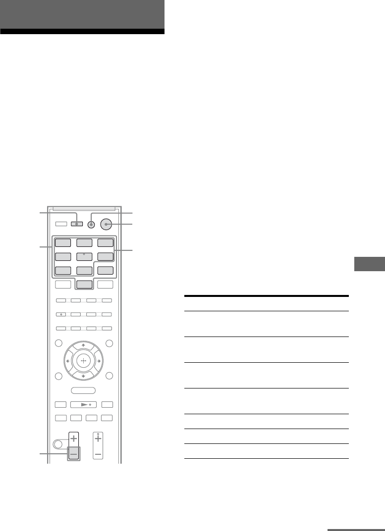
57US
Advanced Settings
Changing the input button
assignments
You can change the initial settings of the input
buttons (BD, DVD, SAT/CATV, VIDEO and
SA-CD/CD) to suit the components in your
system. For example, if you connect a Blu-ray
Disc player to the DVD jack on the receiver,
you can set the DVD button on this remote to
control the Blu-ray Disc player.
Note
You cannot change the remote assignments for TV,
DMPORT and TUNER.
1While holding down the input
button of which you want to
change the assignment, hold
down AV ?/1.
Example: While holding down DVD,
hold down AV ?/1.
2With the AV ?/1 button held,
release the input button you
selected in step 1.
Example: With the AV ?/1 button held,
release DVD.
3Referring to the following table,
press the corresponding
button for the category you
want, then release AV ?/1.
Example: Press 1, then release AV ?/1.
Now you can use the DVD button to
control the Blu-ray Disc player.
Categories and the
corresponding buttons for BD,
DVD, SAT/CATV, VIDEO and
SA-CD/CD
Advanced Settings
.
mM
>
Xx
BD DVD SAT/
CATV
VIDEO SA-CD/
CD
DMPORT TUNER
O
TV
MENU
Input
buttons
MASTER
VOL –
?/1
Numeric
buttons
AV ?/1
INPUT
Categories Press
Blu-ray Disc player
(command mode BD1)a)
1
Blu-ray Disc recorder
(command mode BD3)
2
DVD player
(command mode DVD1)b)
3
DVD recorder
(command mode DVD3)
4
VCR (command mode VTR3) 5
CD player 6
DSSc) 7
continued
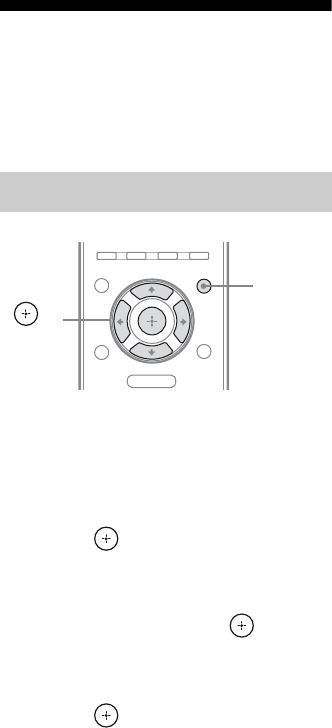
58US
a)The initial setting of the BD button.
For details on the BD1 or BD3 setting, refer to the
operating instructions supplied with the Blu-ray
Disc player or Blu-ray Disc recorder.
b)The initial setting of the DVD button.
Sony DVD recorders are operated with a DVD1 or
DVD3 setting. For details, refer to the operating
instructions supplied with the DVD recorders.
c)The initial setting of the SAT/CATV button.
To clear all remote button
assignments
While holding down MASTER VOL –, press
?/1 and INPUT.
The remote is reset to its initial settings.
Settings and adjustments
using the amplifier menu
By using the amplifier menus, you can make
various adjustments to customize the receiver.
1Press AMP MENU.
“LEVEL” appears on the display.
2Press V/v repeatedly until the
menu you want appears, then
press or b.
3Press V/v repeatedly until the
parameter you want to adjust
appears, then press or b.
4Press V/v repeatedly until the
setting you want appears, then
press .
To return to the previous
display
Press B.
To exit the menu
Press AMP MENU.
Navigating through menus
O
MENU
AMP
MENU
,
V/v/B/b

59US
Advanced Settings
Overview of the menus
You can set the following items using the
AMP MENU. For details of each menu, see
the following pages.
The default settings are underlined.
AMP MENU
LEVEL TEST TONE T. TONE ON
T. TONE OFF
FL LEVEL FL +6.0,…
FL 0.0,...
FL -6.0
CNT LEVEL CNT +6.0,...
CNT 0.0,...
CNT -6.0
FR LEVEL FR +6.0,…
FR 0.0,...
FR -6.0
SR LEVEL SR +6.0,…
SR 0.0,...
SR -6.0
SL LEVEL SL +6.0,…
SL 0.0,...
SL -6.0
SW LEVEL SW +6.0,…
SW 0.0,...
SW -6.0
AUDIO DRC DRC OFF
DRC STD
DRC MAX
TONE BASS BASS +6.0,...
BASS 0.0,...
BASS -6.0
TREBLE TREBLE +6.0,
…TREBLE 0.0,
…TREBLE -6.0
AUDIO A/V SYNC SYNC 20,...
SYNC 1,
SYNC OFF
DUAL MONO MAIN
SUB
MAIN/SUB
NIGHT MODEa) NIGHT ON
NIGHT OFF
INPUT MODEb) AUTO
OPT
SET HDMIc) CTRL HDMI CTRL ON
CTRL OFF
VOL LIMITd) LIMIT MAX,
LIMIT 49,
…LIMIT 1,
LIMIT MIN
PASS THRUd) THRU AUTO
THRU ON
ARCd) ARC ON
ARC OFF
SYSTEM DIMMER DIMMER ON
DIMMER OFF
DISPLAY DSPL ON
DSPL OFF
SLEEP SLEEP OFF,
SLEEP 90M,
…SLEEP 10M
AUTO STBY STBY ON
STBY OFF
SP SETUP CENTER SP CENTER YES
CENTER NO
SUR SP SUR YES
SUR NO
FL DISTe) FL 23FEET,…
FL 10FEET,…
FL 0FEET
CNT DISTe)f) CNT 23FEET,
CNT 10FEET,…
CNT 0FEET
FR DISTe) FR 23FEET,…
FR 10FEET,…
FR 0FEET
SR DISTe)g) SR 23FEET,…
SR 10FEET,…
SR 0FEET
SL DISTe)g) SL 23FEET,….
SL 10FEET,…
SL 0FEET
SW DISTe) SW 23FEET,…
SW 10FEET,…
SW 0FEET
A.CAL MENUh) A.CAL START
A.CAL CLEARi)
S-AIR SETj) S-AIR ID S-AIR ID A
S-AIR ID B
S-AIR ID C
PAIRING START
CONDITION
S-AIR MODE PARTY
SEPARATE
RF CHANGE RF AUTO
RF ON
RF OFF
S-AIR STBY STBY ON
STBY OFF
continued

60US
a)For details, see “Enjoying the sound at low volume
(NIGHT MODE)” (page 34).
b)This parameter is only available when SAT/CATV
input is selected.
c)For details, see “Preparing for the “BRAVIA”
Sync” (page 39).
d)This parameter is only available when “CTRL
HDMI” is set to “CTRL ON”.
e)When the Auto Calibration result is saved, you can
adjust the setting in 1 inch increment.
f) This parameter is only available when “CENTER
SP” is set to “CENTER YES”.
g)This parameter is only available when “SUR SP”
is set to “SUR YES”.
h)For details, see “Performing Auto Calibration”
(page 26).
i) This parameter is only available when the result of
the Auto Calibration is saved.
j) This menu is only available when you insert the
S-AIR transmitter (not supplied). For details, see
“Setting up an S-AIR product” (page 48).
You can adjust the level of each speaker to suit
your preference.
xTEST TONE
You can adjust the speaker levels while
listening to the test tone from your listening
position.
To adjust the speaker levels
xFL LEVEL (Front left speaker
level)
xCNT LEVEL (Center speaker
level)
xFR LEVEL (Front right speaker
level)
xSR LEVEL (Surround right
speaker level)
xSL LEVEL (Surround left speaker
level)
xSW LEVEL (Subwoofer level)
1Press V/v repeatedly until
“TEST TONE” appears, then
press or b.
2Press V/v repeatedly until
“T. TONE ON” appears, then
press .
The test tone is emitted from each speaker
in sequence as follows:
Front left t Center t Front right t
Surround right t Surround left t
Subwoofer
3Press B until “TEST TONE”
appears.
4Press V/v repeatedly to select
the desired speaker, then press
or b.
The test tone is emitted from the speaker
that is being adjusted only.
• FL LEVEL, CNT LEVEL, FR LEVEL,
SR LEVEL, SL LEVEL, SW LEVEL
Notes
• “CNT LEVEL” does not appear when you set
“CENTER NO” in the “SP SETUP” setting.
• “SR LEVEL” and “SL LEVEL” do not
appear when you set “SUR NO” in the
“SP SETUP” setting.
5Press V/v repeatedly to adjust
the speaker level, then press
.
You can adjust from –6.0 dB to +6.0 dB
in 0.5 dB steps.
Note
If you do not adjust for a certain period, the test
tone is emitted from the next speaker in
sequence.
6Repeat step 4 and 5 to adjust
the other speaker level.
7After you have finished making
adjustments, press V/v
repeatedly until “TEST TONE”
appears, then press or b.
LEVEL menu

61US
Advanced Settings
8Press V/v repeatedly until
“T. TONE OFF” appears, then
press .
When a test tone is not output
from the speakers
• The speaker cords may not be connected
securely.
• The speaker cords may have the short-circuit
problem.
Note
The test tone signals are not output from the HDMI
OUT jack.
xAUDIO DRC
You can compress the dynamic range of the
sound track. This may be useful when you
want to watch movies at low volume. AUDIO
DRC only applies to Dolby Digital sources.
• DRC OFF: Does not compress dynamic
range.
• DRC STD: Compress dynamic range as
intended by the recording engineer.
• DRC MAX: Compress dynamic range fully.
Tip
Audio dynamic range compression lets you
compress the dynamic range of the soundtrack based
on the dynamic range information included in the
Dolby Digital signal.
“DRC STD” is the standard setting, but it only
enacts light compression. Therefore, we recommend
using the “DRC MAX” setting. This greatly
compresses the dynamic range and lets you view
movies late at night at low volumes. Unlike analog
limiters, the levels are predetermined and provide a
very natural compression.
You can adjust the tonal quality (bass and
treble level) of the speakers.
xBASS
xTREBLE
To adjust the tone level
1Press V/v repeatedly until “BASS” or
“TREBLE” appears, then press or b.
2Press V/v repeatedly until bass or
treble level appears, then press .
You can adjust from –6.0 dB to +6.0 dB in
0.5 dB steps.
You can make the settings for the audio to suit
your preference.
xA/V SYNC
You can delay the sound output using this
function when the image is slower than the
sound.
• SYNC OFF: Does not adjust.
• SYNC 1 – 20: Adjusts from 1 (10 ms) to 20
(200 ms) in 1 (10 ms) steps.
Notes
• You may not be able to adjust the delay between
sound and image perfectly using this function.
• This function is useful only for Dolby Digital, DTS
and Linear PCM (2ch) input by optical and coaxial
audio input signals.
xDUAL MONO
You can select the language you want to listen
to during digital broadcast. This feature only
functions for Dolby Digital sources.
• MAIN: Outputs sound of the main language.
• SUB: Outputs sound of the sub language.
• MAIN / SUB: Outputs sound of the main
language through the front left speaker and
sound of the sub language through the front
right speaker simultaneously.
TONE menu
AUDIO menu
continued

62US
xINPUT MODE
You can select the audio input mode setting
when you connect satellite tuner or cable
television tuner to both HDMI IN jack and
optical digital input jack on the receiver and
SAT/CATV input has been selected.
• AUTO: Gives priority to HDMI audio
signals if there are both digital (HDMI and
optical) connections.
• OPT: Specifies the digital audio signals
input to the SAT/CATV OPT IN jack.
You can make various settings to suit your
preference.
xDIMMER
You can change the brightness of the display.
• DIMMER ON: Low lighting.
• DIMMER OFF: Bright lighting.
xDISPLAY
You can change the display setting.
• DSPL ON: The display appears all the time.
• DSPL OFF: The display appears when you
operate the receiver.
xSLEEP
You can set the receiver to turn off at a preset
time when you want to fall asleep listening to
music. You can preset the time in 10 minutes
decrements.
To activate the sleep timer
1Press V/v repeatedly until “SLEEP”
appears, then press or b.
2Press V/v repeatedly to select the
preset time, then press .
The minutes display (the remaining time)
changes cyclically as follows:
xAUTO STBY
You can set the receiver switch to standby
mode when you do not operate the receiver for
about 30 minutes and when there is no signals
input to the receiver.
• STBY ON: Switches to standby mode.
• STBY OFF: Does not switch to standby
mode.
You can set the distance of the speakers
connected to this receiver.
xCENTER SP
xSUR SP
To set the speaker connection
1Press V/v repeatedly until the speaker
you want to set appears, then press
or b.
• CENTER SP: Select the center speaker.
• SUR SP: Select the surround speaker.
2Press V/v repeatedly until the setting
you want appears, then press .
• CENTER (SUR) YES: Selects when you
connect the speaker(s).
• CENTER (SUR) NO: Selects when you
do not connect the speaker(s).
xFL DIST (Front left speaker
distance)
xCNT DIST (Center speaker
distance)
xFR DIST (Front right speaker
distance)
xSR DIST (Surround right speaker
distance)
xSL DIST (Surround left speaker
distance)
xSW DIST (Subwoofer distance)
SYSTEM menu
SLEEP OFF SLEEP 10M SLEEP 20M
SLEEP 90M SLEEP 80M … SLEEP 30M
SP SETUP menu

63US
Additional Information
To set the speaker distance
from your listening position
1Press V/v repeatedly until the speaker
you want to adjust appears, then press
or b.
• FL DIST, CNT DIST, FR DIST,
SR DIST, SL DIST, SW DIST
Notes
• “CNT DIST” does not appear when you set
“CENTER NO” in the “SP SETUP” setting.
• “SR DIST” and “SL DIST” do not appear
when you set “SUR NO” in the “SP SETUP”
setting.
2Press V/v repeatedly to set the
speaker distance, then press .
You can adjust from 0FEET to 23FEET.
Tip
When the Auto Calibration result is saved, you
can adjust the speakers distance in 1 inch steps.
If the Auto Calibration result is not saved, you
can adjust the speakers distance in 1/4 feet steps.
3Repeat step 1 and 2 to adjust the other
speaker distance.
Glossary
xDeep Color
Video signals for which the color depth of
signals passing through an HDMI jack have
been raised.
The number of colors that could be expressed
by 1 pixel was 24 bits (16,777,216 colors) with
the current HDMI jack. However, the number
of colors which can be expressed by 1 pixel
will be 36 bits, etc., when the receiver
corresponds to Deep Color.
Since the gradation of the depth of a color can
be expressed more finely with more bits,
continuous color changes can be more
smoothly expressed.
xDigital Cinema Sound (DCS)
A unique sound reproduction technology for
home theater developed by Sony, in
cooperation with Sony Pictures Entertainment,
for enjoying the exciting and powerful sound
of movie theaters at home. With this “Digital
Cinema Sound” developed by integrating a
DSP (Digital Signal Processor) and measured
data, the ideal sound field intended by
filmmakers can be experienced at home.
xDolby Digital
This movie theater sound format is more
advanced than Dolby Surround Pro Logic. In
this format, the surround speakers output
stereo sound with an expanded frequency
range, and a subwoofer channel for deep bass
is independently provided. This format is also
called “5.1” with the subwoofer channel
designed as the 0.1 channel (since it functions
only when a deep bass effect is needed). All
six channels in this format are recorded
separately for superior channel separation.
Furthermore, since all the signals are
processed digitally, less signal degradation
occurs.
Additional Information
continued
64US
xDolby Pro Logic II
Dolby Pro Logic II creates five full-bandwidth
output channels from 2 channel sources. This
is done using an advanced, high-purity matrix
surround decoder that extracts the spatial
properties of the original recording without
adding any new sounds or tonal colorations.
xDolby Surround (Dolby Pro
Logic)
Audio processing technology developed by
Dolby Laboratories, Inc. Center and mono
surround information is matrixed into two
stereo channels. When reproduced, audio is
decoded and output in 4 channel surround
sound. This is the most common audio
processing method for DVD-video.
xDTS Digital Surround
Digital audio encoding/decoding technology
for theaters developed by DTS, Inc. It
compresses audio less than Dolby Digital,
delivering a higher quality sound
reproduction.
xHDMI (High-Definition
Multimedia Interface)
HDMI (High-Definition Multimedia
Interface) is an interface that supports both
video and audio on a single digital connection,
allowing you to enjoy high quality digital
picture and sound. The HDMI specification
supports HDCP (High-bandwidth Digital
Contents Protection), a copy protection
technology that incorporates coding
technology for digital video signals.
xL.F.E. (Low Frequency Effects)
Sound effects of low frequencies which are
output from a subwoofer in Dolby Digital or
DTS, etc. By adding a deep bass with a
frequency between 20 to 120 Hz, audio
becomes more powerful.
xS-AIR (Sony Audio Interactive
Radio frequency)
Recent times have seen the rapid spread of
DVD media, Digital Broadcasting, and other
high quality media.
To ensure that the subtle nuances of these high
quality media are transmitted with no
deterioration, Sony has developed a
technology called “S-AIR” for the radio
transmission of digital audio signals with no
compression, and has incorporated this
technology into the EZW-RT10/EZW-T100.
This technology transfers digital audio signals
with no compression using the 2.4 GHz band
range of ISM band (Industrial, Scientific, and
Medical band), such as wireless LANs and
Bluetooth applications.
xS-Master
S-Master is an all-digital amplifier technology
developed by Sony, which effectively
minimizes the occurrence of sound
fragmentation and jitter, delivering superb
dialog clarity and faithful reproduction of the
original sound. The compact amplifier section
supports a higher power efficiency and
improved thermal performance.
xSampling frequency
To convert analog audio to digital, analog data
should be quantified. This process is called
sampling, and the number of times per second
the analog data is quantified is called the
sampling frequency. A standard music CD
stores data quantified at 44,100 times per
second, which is expressed as a sampling
frequency of 44.1 kHz. Generally speaking, a
higher sampling frequency means better sound
quality.

65US
Additional Information
xTSP (Time Stretched Pulse)
A TSP signal is a highly precise measuring
signal that utilizes impulse energy, measuring
a wide band, from low to high, in a short
period.
The amount of energy used to measure signals
is important to ensure measurement accuracy
in a normal indoor environment. Using TSP
signals makes it possible to measure signals
effectively.
xx.v.Color
“x.v.Color” enables the more faithful
reproduction of various colors such as the
brilliant colors of flowers and the turquoise
blue of the southern ocean.
“x.v.Color” is a promotion name given to the
products that have the capability to realize a
wide color space based on the xvYCC
specifications and is a trademark of Sony
Corporation.
xvYCC is an international standard of the
technical specifications of the extended-gamut
color space for video signals. The color gamut
of xvYCC is wider than the one of sRGB that
is used with the current television system.
Precautions
On safety
Should any solid object or liquid fall into the
cabinet, unplug the receiver and have it
checked by qualified personnel before
operating it any further.
On power sources
• Before operating the receiver, check that the
operating voltage is identical with your local
power supply.
The operating voltage is indicated on the
nameplate on the back of the receiver.
• The unit is not disconnected from the AC
power source (mains) as long as it is
connected to the wall outlet, even if the unit
itself has been turned off.
• If you are not going to use the receiver for a
long time, be sure to disconnect the receiver
from the wall outlet. To disconnect the AC
power cord, grasp the plug itself; never pull
the cord.
• One blade of the plug is wider than the other
for the purpose of safety and will fit into the
wall outlet only one way. If you are unable to
insert the plug fully into the outlet, contact
your dealer.
• The AC power cord must be changed only at
a qualified service shop.
On heat buildup
Although the receiver heats up during
operation, this is not a malfunction. If you
continuously use this receiver at a large
volume, the cabinet temperature of the top,
side and bottom rises considerably. To avoid
burning yourself, do not touch the cabinet.
continued
66US
On placement
• Place the receiver in a location with adequate
ventilation to prevent heat buildup and
prolong the life of the receiver.
• Do not place the receiver near heat sources,
or in a place subject to direct sunlight,
excessive dust, or mechanical shock.
• Do not place anything on top of the cabinet
that might block the ventilation holes and
cause malfunctions.
• Do not place the receiver near equipment
such as a TV, VCR, or tape deck. If the
receiver is being used in combination with a
TV, VCR, or tape deck, and is placed too
close to that equipment, noise may result,
and picture quality may suffer. This is
especially likely when using an indoor
antenna. Therefore, we recommend using an
outdoor antenna.
• Use caution when placing the receiver or
speakers on surfaces that have been specially
treated (with wax, oil, polish, etc.) as
staining or discoloration of the surface may
result.
On operation
Before connecting other components, be sure
to turn off and unplug the receiver.
If you encounter color
irregularity on a nearby TV
screen
The center speaker is magnetically shielded to
allow it to be installed near a TV set. However,
color irregularities may still be observed on
certain types of TV sets. As the front speakers,
surround speakers and subwoofer are not
magnetically shielded, we recommend that
you place them slightly further away from TV
set (page 15).
If color irregularity is
observed...
Turn off the TV set, then turn it on again after
15 to 30 minutes.
If color irregularity is observed
again...
Place the speaker further away from the TV
set.
If howling occurs
Reposition the speakers or turn down the
volume on the receiver.
On cleaning
• Clean the cabinet, panel, and controls with a
soft dry cloth. Do not use any type of
abrasive pad, scouring powder, scrubbing
brush or sponge.
• If it is stained with oil or fingerprints, breath
on the surface and wipe it with soft dry cloth.
On S-AIR function
• As the S-AIR product(s) transmits sound by
radio waves, sound may skip when radio
waves are obstructed. This is a characteristic
of radio waves and is not malfunction.
• As the S-AIR product(s) transmits sound by
radio waves, equipment that generates
electromagnetic energy, such as a
microwave oven, may interfere with sound
transmission.
• As the S-AIR product(s) uses the radio
waves that share the same frequency as other
wireless systems, such as wireless LAN or
Bluetooth devices, interference or poor
transmission may result. In this case, take
the following steps:
– Avoid placing the S-AIR product(s) near
other wireless systems.
– Avoid using the S-AIR product(s) and the
other wireless systems at the same time.
– The transmission may be improved by
changing the transmission channel
(frequency) of the other wireless
system(s). For details, refer to the
operating instructions of the other wireless
system(s).

67US
Additional Information
• The transmission distance differs depending
on the usage environment. Find a location
where transmission between the S-AIR main
unit and sub unit is most effective, and
install the S-AIR main unit and sub unit
there.
• Place the S-AIR product(s) on the stable
surface off the floor.
• Poor transmission may occur and the
transmission distance may be too short if the
following conditions exist:
– There is a wall/floor made of reinforced
concrete or stone between the S-AIR
product(s).
– There is an iron divider/door or furniture/
electric product made of fireproof glass,
metal, etc., between the S-AIR product(s).
If you have any questions or problems
concerning your receiver, please consult your
nearest Sony dealer.
Troubleshooting
If you experience any of the following
difficulties while using the receiver, use this
troubleshooting guide to help you remedy the
problem.
Audio
There is no sound, no matter which
component is selected, or only a very
low-level sound is heard.
• Check that the speakers and components
are connected securely.
• Check that both the receiver and all
components are turned on.
• Check that MASTER VOLUME is not set
to “VOLUME MIN”.
• Press MUTING to cancel the muting
function.
• Check that you have selected the correct
component with the input buttons.
• The protective device on the receiver has
been activated. Turn off the receiver,
eliminate the short-circuit problem, and
turn on the power again.
• Check that the INPUT MODE setting is
correct for SAT/CATV input.
There is no sound from a specific
component.
• Check that the component is connected
correctly to the audio input jacks for that
component.
• Check that the cord(s) used for the
connection is (are) fully inserted into the
jacks on both the receiver and the
component.
There is no sound from one of the front
speakers.
• Make sure you have connected to both the
L and R jacks of an analog component, and
not only to either the L or R jack. Use an
audio cord (not supplied).
continued

68US
There is no sound from digital sources
(from OPTICAL input jack).
• Check that the INPUT MODE is set to
“OPT” for SAT/CATV input (page 62).
• Set “ARC” to “ARC OFF” when no sound
is output from TV OPT IN jack during TV
input (page 45).
There is severe hum or noise.
• Check that the speakers and components
are connected securely.
• Check that the connecting cords are away
from a transformer or motor, and at least
10 feet (3 meters) away from a TV set or
fluorescent light.
• Move your audio components away from
the TV.
• The plugs and jacks are dirty. Wipe them
with a cloth slightly moistened with
alcohol.
There is pop noise from a specific
component connected to this receiver
when you turn on the component.
• Check that the INPUT MODE is set to
“OPT” for SAT/CATV input (page 62).
There is no sound, or only a very low-
level sound is heard from the center/
surround speakers.
• Select “MOVIE-D.C.S.-” (page 33).
• Adjust the speaker level (page 60).
• Check that the speakers are connected
securely.
There is no sound from the subwoofer.
• Check that the subwoofer is connected
correctly and securely.
The surround effect cannot be
obtained.
• Make sure the sound field function is on
(press SOUND FIELD +/–).
• Sound fields do not function for signals
with a sampling frequency of more than
48 kHz.
Dolby Digital or DTS multi channel
sound is not reproduced.
• Check that the DVD, etc. you are playing
is recorded in Dolby Digital or DTS
format.
• When connecting the DVD player, etc., to
the digital input jacks of this receiver,
check the audio setting (the settings for the
audio output) of the connected component.
There is no sound from the component
connected to the DIGITAL MEDIA PORT
adapter.
• Adjust the volume of this receiver.
• The DIGITAL MEDIA PORT adapter
and/or component is not connected
correctly. Turn off the receiver, then
reconnect the DIGITAL MEDIA PORT
adapter and/or component.
• Check the DIGITAL MEDIA PORT
adapter and/or component device to make
sure it supports this receiver.
Video
There is no picture or an unclear
picture appears on the TV screen or
monitor.
• Make sure you have connected the video
output of your video component to the TV.
• Move your audio components away from
the TV.
• Depending on the DIGITAL MEDIA
PORT adapter, video output may not be
possible.

69US
Additional Information
HDMI
The source sound input to the HDMI
jack on the receiver is not output from
the receiver or the TV speaker.
• Check the HDMI connection (page 21).
• Make sure “CTRL HDMI” is set to
“CTRL ON” in SET HDMI menu.
• You cannot listen to the Super Audio CD
by connecting HDMI.
• Depending on the playback component,
you may need to set up the component.
Refer to the operating instructions
supplied with each component.
• Be sure to use a High Speed HDMI cable
when you view images or listen to sound
during Deep Color transmission.
The source image input to the HDMI
jack on the receiver is not output from
the TV.
• Check the HDMI connection (page 21).
• Depending on the playback component,
you may need to set up the component.
Refer to the operating instructions
supplied with each component.
• Be sure to use a High Speed HDMI cable
when you view images or listen to sound
during Deep Color transmission.
The Control for HDMI function does not
work.
• Check the HDMI connection (page 21).
• Make sure “CTRL HDMI” is set to
“CTRL ON” in SET HDMI menu.
• Make sure the connected component is
compatible with the Control for HDMI
function.
• Check the Control for HDMI settings on
the connected component. Refer to the
operating instructions of the connected
component.
• Repeat the procedures of “Preparing for
the “BRAVIA” Sync” if you change the
HDMI connection, connect/disconnect the
AC power cord, or there is a power failure
(page 39).
No sound is output from the receiver
and TV speaker while using the System
Audio Control function.
• Make sure the TV is compatible with the
System Audio Control function.
• If you cannot listen to the sound of a
component connected to the receiver
– Select the appropriate input when you
want to watch a program on a
component connected via HDMI
connection to the receiver.
– Change the TV channel when you want
to watch a TV broadcast.
– Select the component or input you want
to watch when you watch a program on
the component connected to the TV.
Refer to the operating instructions of the
TV on this operation.
When the receiver is in standby mode,
there is no image or sound on the TV.
• When the receiver is in standby mode,
image and sound are output from the
HDMI component selected the last time
you turned off the receiver. If you are
enjoying other component, play the
component and perform the One-Touch
Play operation, or turn on the receiver to
select the HDMI component you want to
enjoy.
• Make sure “PASS THRU” is set to
“THRU ON” in the SET HDMI menu if
you connect components not compatible
with the “BRAVIA” Sync to the receiver
(page 44).
The volume turns down when the
output method changes from the TV
speaker to the speakers connected to
the receiver.
• The Volume Limit function is working
(page 42).
continued

70US
S-AIR function
S-AIR connection is not established
(sound transmission is not
established), e.g., the indicator of the
S-AIR sub unit turns off, flashes, or
turns red.
• If you use another S-AIR main unit, place
it more than 25 feet (8 meters) away from
this S-AIR main unit.
• Confirm the S-AIR IDs of the S-AIR main
unit and S-AIR sub unit (page 50).
• Another S-AIR sub unit is paired to the
S-AIR main unit. Pair the desired S-AIR
sub unit with the S-AIR main unit (page
51).
• The S-AIR main unit is paired to another
S-AIR sub unit. Cancel pairing.
• Place the S-AIR main unit and S-AIR sub
unit separately from other wireless
devices.
• Avoid using any other wireless devices.
• The S-AIR sub unit is turned off. Make
sure the AC power cord is connected and
turn on the S-AIR sub unit.
No sound is heard from the S-AIR
product.
• If you use another S-AIR main unit, place
it more than 25 feet (8 meters) away from
this S-AIR main unit.
• Confirm the S-AIR IDs of the S-AIR main
unit and S-AIR sub unit (page 50).
• Confirm the pairing setting (page 51).
• Place the S-AIR main unit and S-AIR sub
unit closer to each other.
• Avoid use of equipment that generates
electromagnetic energy, such as a
microwave oven.
• Place the S-AIR main unit and S-AIR sub
unit separately from other wireless
devices.
• Avoid using any other wireless devices.
• Change the “RF CHANGE” setting (page
55).
• Change the S-AIR ID settings of the
S-AIR main unit and S-AIR sub unit.
• Turn off the receiver and S-AIR sub unit,
then turn on again.
There is noise or the sound skips.
• If you use another S-AIR main unit, place
it more than 25 feet (8 meters) away from
this S-AIR main unit.
• Place the S-AIR main unit and S-AIR sub
unit closer to each other.
• Avoid use of equipment that generates
electromagnetic energy, such as a
microwave oven.
• Place the S-AIR main unit and S-AIR sub
unit separately from other wireless
devices.
• Avoid using any other wireless devices.
• Change the “RF CHANGE” setting (page
55).
• Change the S-AIR ID settings of the
S-AIR main unit and S-AIR sub unit.
“HP NO LINK” and “VOLUME MIN”
appear alternately in the display and
the volume of the receiver becomes
minimum.
• Volume becomes minimum when you turn
off the surround amplifier with
headphones connected or if the radio
reception is poor. Check the radio
reception and adjust the volume level to
restore the sound from the headphones.
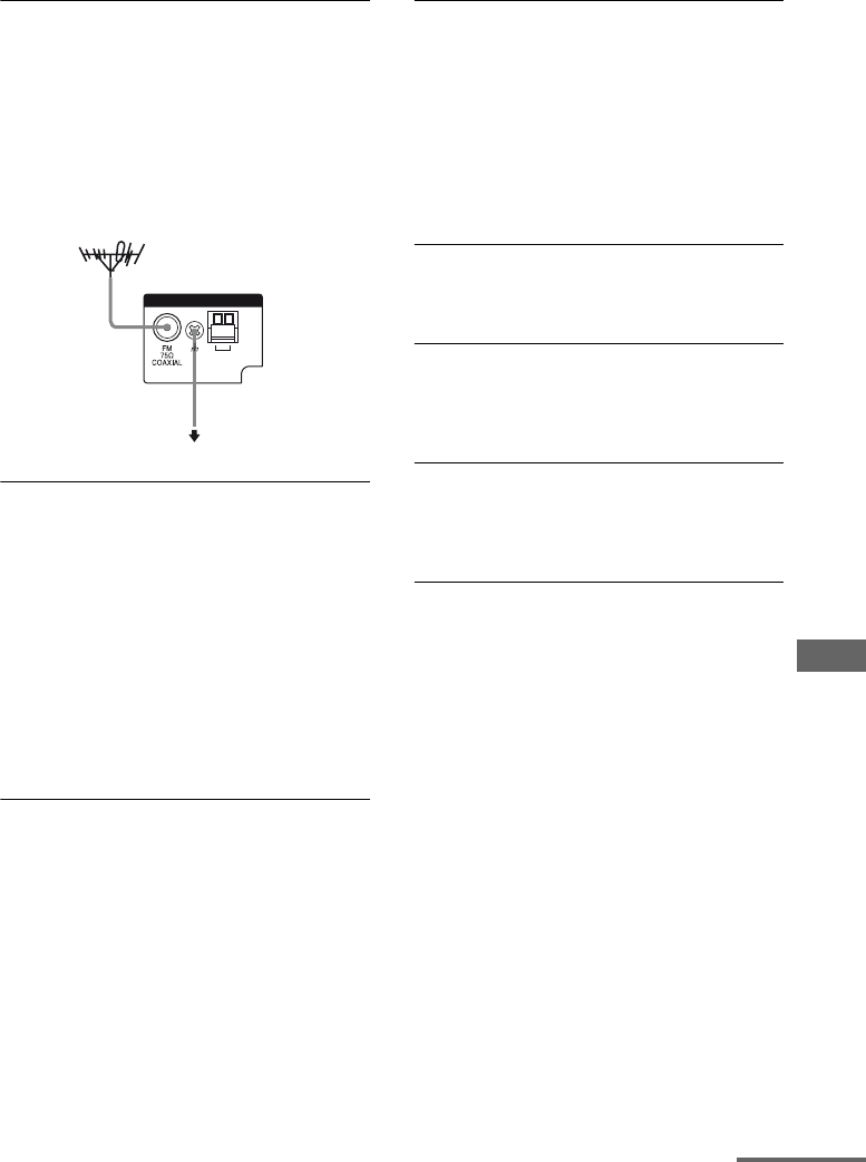
71US
Additional Information
Tuner
The FM reception is poor.
• Use a 75-ohm coaxial cable (not supplied)
to connect the receiver to an outdoor FM
antenna as shown below. If you connect
the receiver to an outdoor antenna, ground
it against lightning. To prevent a gas
explosion, do not connect the ground wire
to a gas pipe.
Radio stations cannot be tuned in.
• Check that the antennas are connected
securely. Adjust the antennas and connect
an external antenna, if necessary.
• The signal strength of the stations is too
weak (when tuning in with automatic
tuning). Change to monaural reception
(page 35).
• No stations have been preset or the preset
stations have been cleared (when tuning
by scanning preset stations). Preset the
stations (page 37).
Remote commander
The remote does not function.
• Point the remote at the remote sensor on
the receiver.
• Remove any obstacles in the path between
the remote and the receiver.
• Replace all the batteries in the remote with
new ones, if they are weak.
• Make sure you select the correct input on
the remote.
Others
The POWER/ACTIVE STANDBY
indicator is flashing.
• The receiver is in protection mode. Turn
off the receiver and turn it on again.
The receiver is turned off
automatically.
• The AUTO STBY function is working
(page 62).
AM
ANTENNA
Receiver
To ground
Ground wire
(not supplied)
Outdoor FM antenna
continued

72US
Error messages
If an error message appears while you perform
Auto Calibration, see “When error codes
appear” (page 28) to solve the problem.
If you are unable to remedy the
problem using the
troubleshooting guide
Clearing the receiver’s memory may remedy
the problem (page 24). However, note that all
memorized settings will be reset to their initial
settings and you will have to readjust all
settings on the receiver.
If the problem persist
Consult your nearest Sony dealer. Note that if
service personnel changes some parts during
repair, these parts may be retained.
In the event of a problem with S-AIR function,
have a Sony dealer check the entire system
together (S-AIR main unit and S-AIR sub
unit).
Reference sections for clearing
the receiver’s memory
Specifications
AUDIO POWER
SPECIFICATIONS
Amplifier section
POWER OUTPUT AND TOTAL HARMONIC
DISTORTION:
(FTC)
(Models of area code U2 only)
FRONT L + FRONT R
With 3 ohm loads, both
channels driven, from 180
– 20,000 Hz; rated 84 watts
per channel minimum
RMS power, with no more
than 1% total harmonic
distortion from 250
milliwatts to rated output.
POWER OUTPUT (reference)
FRONT L/FRONT R/CENTER/SUR L/SUR R
167 W (per channel at
3 ohms, 1 kHz)
SUBWOOFER 165 W (at 3 ohms, 60 Hz)
Inputs
Analog Sensitivity: 1 V/50 kohms
Digital (Coaxial) Impedance: 75 ohms
FM tuner section
Tuning range 87.5 – 108.0 MHz
(100 kHz step)
Antenna FM wire antenna
Antenna terminals 75 ohms, unbalanced
Intermediate frequency
10.7 MHz
AM tuner section
Tuning range
Antenna AM loop antenna
Intermediate frequency
450 kHz
To clear See
All memorized settings page 24
Area code Tuning scale
10 kHz step 9 kHz step
U2, CA2 530 –
1,710 kHz
531 –
1,710 kHz

73US
Additional Information
General
Power requirements
Power output (DIGITAL MEDIA PORT)
DC OUT: 5 V, 0.7A MAX
Power consumption
Power consumption (during standby mode)
0.3 W (When Control for
HDMI and S-AIR standby
are set to off)
Dimensions (w/h/d) (Approx.)
17 in × 2 5/8 in × 12 1/8 in
(430 mm × 66.5 mm ×
306 mm)
including projecting parts
and controls
Mass (Approx.) 7 lb 8 oz (3.4 kg)
Speaker section
HT-SF370 only
• Front speaker (SS-MSP37F)
• Surround speaker (SS-SRP37F)
• Center speaker (SS-CNP37)
Front/Surround speaker
Full range
Center speaker Full range, magnetically
shielded
Speaker unit
Front/Surround speaker
2 5/8 in (65 mm), cone type
Center speaker 1 3/16 in × 2 3/8 in (30 mm
× 60 mm), cone type
Enclosure type
Front/Surround speaker
Bass reflex
Center speaker Acoustic suspension
Rated impedance 3 ohms
Dimension (w/h/d) (Approx.)
Front speaker 4 1/2 in × 32 3/4 in ×
3 3/8 in (113 mm ×
830 mm × 83 mm)
(without stand)
12 1/2 in × 40 in – 53 in ×
12 1/2 in (315 mm ×
1,015 mm – 1,345 mm ×
315 mm) (with stand)
Surround speaker 4 3/8 in × 21 3/8 in ×
3 1/8 in (108 mm ×
540 mm × 78 mm)
(without stand)
11 1/2 in × 41 1/4 in –
48 5/8 in × 11 1/2 in
(290 mm × 1,045 mm –
1,235 mm × 290 mm)
(with stand)
Center speaker 15 in × 2 in × 2 5/8 in
(380 mm × 50 mm ×
64 mm) (with foot)
Mass (Approx.)
Front speaker 3 lb 9 oz (1.6 kg)
(without stand)
7 lb 5 oz (3.3 kg)
(with stand)
Surround speaker 2 lb 7 oz (1.1 kg)
(without stand)
5 lb 12 oz (2.6 kg)
(with stand)
Center speaker 0 lb 14 oz (0.38 kg)
(with foot)
• Subwoofer (SS-WP37)
Speaker unit 6 3/8 in (160 mm), cone
type
Enclosure type Bass reflex
Rated impedance 3 ohms
Dimensions (w/h/d) (Approx.)
8 3/4 in × 15 5/8 in ×
12 7/8 in (220 mm ×
395 mm × 325 mm)
(with foot)
Mass (Approx.) 12 lb 6 oz (5.6 kg)
(with foot)
Area code Power requirements
U2, CA2 120 V AC, 60 Hz
Area code Power consumption
U2, CA2 110 W
continued

74US
HT-SS370 only
• Front/Surround speaker (SS-TSB101)
• Center speaker (SS-CTB101)
Front/Surround speaker
Full range
Center speaker Full range, magnetically
shielded
Speaker unit
Front/Surround speaker
2 1/4 in × 3 1/4 in (55 mm
× 80 mm), cone type
Center speaker 1 3/16 in × 2 3/8 in (30 mm
× 60 mm), cone type
Enclosure type
Front/Surround speaker
Bass reflex
Center speaker Acoustic suspension
Rated impedance 3 ohms
Dimension (w/h/d) (Approx.)
Front/Surround speaker
3 in × 8 7/8 in × 2 7/8 in
(75 mm × 225 mm ×
71 mm) (with foot)
Center speaker 11 1/2 in × 1 15/16 in ×
1 15/16 in (290 mm ×
49 mm × 49 mm)
(with foot)
Mass (Approx.)
Front/Surround speaker
1 lb (0.45 kg) (with foot)
Center speaker 0 lb 10 oz (0.28 kg)
(with foot)
• Subwoofer (SS-WSB101)
Speaker unit 6 3/8 in (160mm),
cone type
Enclosure type Bass reflex
Rated impedance 3 ohms
Dimensions (w/h/d) (Approx.)
10 1/4 in × 12 5/8 in ×
10 1/4 in (260 mm ×
320 mm × 260 mm)
(with foot)
Mass (Approx.) 11 lb 8 oz (5.2 kg)
(with foot)
Design and specifications are subject to
change without notice.
For details on the area code of the
component you are using, see page 4.
Halogenated flame retardants are not used in
the certain printed wiring boards.

75US
Additional Information
Index
Numerics
5.1 channel 15
A
AUDIO DRC 61
Audio Return Channel
(ARC) 45
AUTO CALIBRATION 25
AUTO STBY 62
B
Blu-ray Disc player
connecting 22
playback 32
“BRAVIA” Sync
preparing 39
C
CD player
connecting 20
playback 32
D
Deep Color 63
Digital Cinema Sound
(DCS) 63
DIGITAL MEDIA PORT
adapter
connecting 20
playback 32
DIMMER 62
DISPLAY 62
Dolby Digital 63
DTS 64
DVD player
connecting 22
playback 32
DVD recorder
connecting 23
E
Error messages 72
H
HDMI
connecting 22
HDMI Pass Through 44
I
Initial setup 24
INPUT MODE 62
M
Menu
A.CAL MENU 59
AUDIO 59
LEVEL 59
S-AIR SET 59
SET HDMI 59
SP SETUP 59
SYSTEM 59
TONE 59
Muting 30
N
Naming 38
NIGHT MODE 34
O
One-Touch Play 41
P
Pairing 51
R
Remote commander 11
S
S-AIR 47
Satellite tuner, cable
television tuner
connecting 22
playback 31
Scene Select 46
Selecting
component 29
SLEEP 62
Sound fields
selecting 33
Speakers
connecting 18
installing 15
Super Audio CD player
connecting 20
playback 32
System Audio Control 41
System Power Off 43
T
Theater Mode 46
Tuner
connecting 24
Tuning
automatically 35
directly 36
to preset stations 37
TV
connecting 19, 22
playback 31
V
Volume Limit 42

Sony Corporation Printed in Malaysia
(1)
