Sophos AP55 Sophos Wireless Access Point AP55 User Manual 0224
Sophos Ltd Sophos Wireless Access Point AP55 0224
UserManual.wiki
>
Sophos
>
AP55 User Manual
>
user manual 0224
Contents
1.
user manual safety
2.
user manual 0224
3.
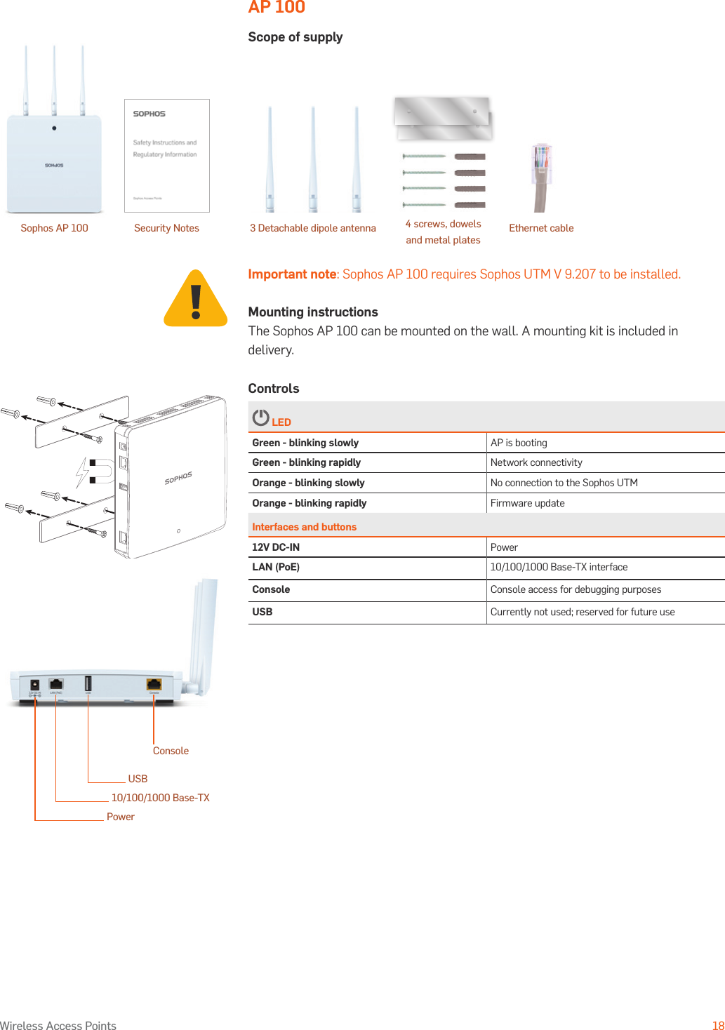
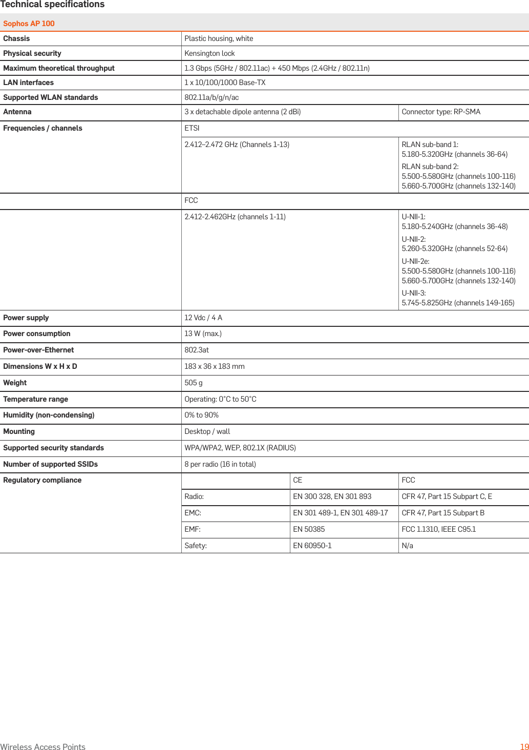
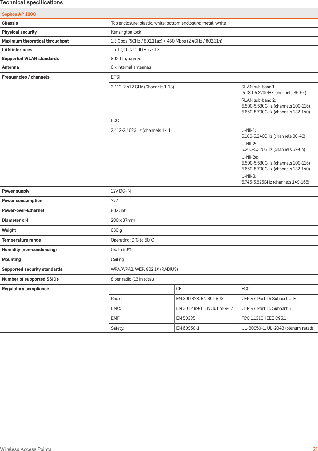
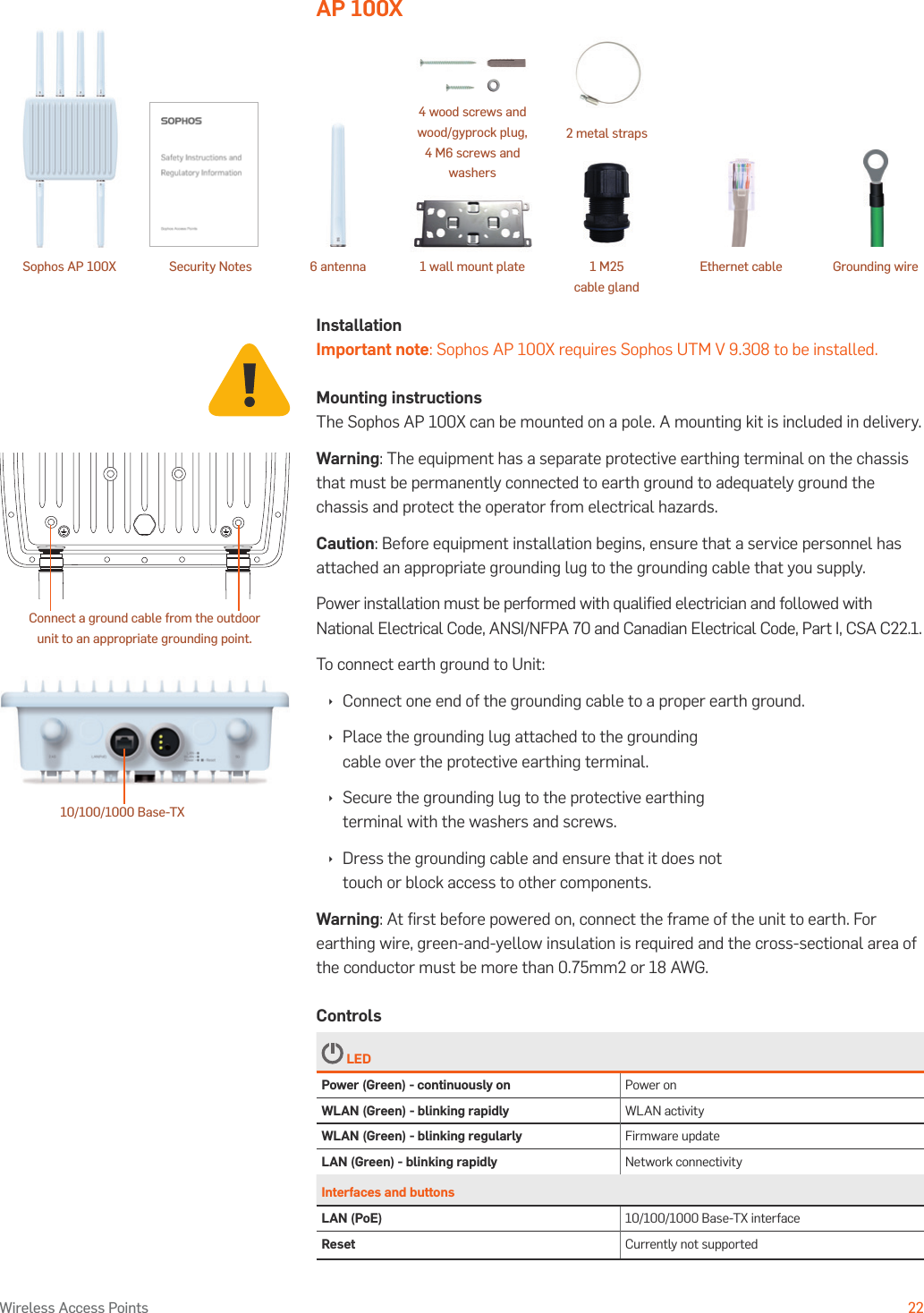
User Manual
4.
Safety Instructions
user manual 0224
Navigation menu
Upload a User Manual
Namespaces
Wiki Guide
HTML
PDF
Info
Views
User Manual
Discussion / Help
Navigation