Soundcast 50RFM Wireless Audio Device Module User Manual UserManual

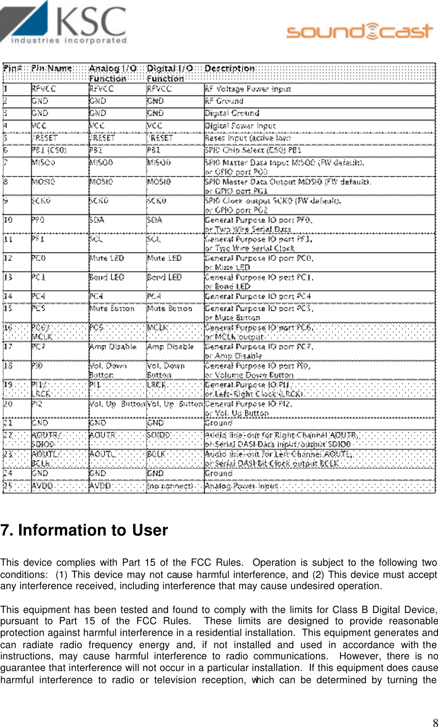
KSC Industries, Inc. Wireless Audio Device Module UserManual

user manual

                                                       USER MANUAL  SOUNDCAST 50RFM WIRELESS AUDIO SYSTEMS  KSC INDUSTRIES, INC. 881 KUHN DIRVE, BUILDING 200 CHULA VISTA, CA 91914
                                                      1 TABLE OF CONTENT  1. GENERAL DESCRIPTION ........................................................................................ 2 2. FEATURES ................................................................................................................... 2 3. ELECTRICAL SPECIFICATIONS........................................................................... 3 3.1 OPERATING CONDITIONS – SOUNDCAST 50RFM TRANSMITTER......................... 3 3.2 ABSOLUTE MAXIMUM RATINGS – SOUNDCAST 50RFM TRANSMITTER............... 3 3.3 OPERATING CONDITIONS – SOUNDCAST 50RFM RECEIVER................................ 4 3.4 ABSOLUTE MAXIMUM RATINGS – SOUNDCAST 50RFM RECEIVER...................... 4 4. AUDIO CHARACTERISTICS ................................................................................... 5 5.  RF CHARACTERISTICS .......................................................................................... 5 5.1 RF CHARACTERISTICS - SOUNDCAST 50RFM TRANSMITTER AND RECEIVER.... 5 6.  PIN DESCRIPTION .................................................................................................... 6 6.1 PIN DESCRIPTION - SOUNDCAST 50RFM TRANSMITTER...................................... 6 6.2 PIN DESCRIPTION - SOUNDCAST 50RFM RECEIVER............................................. 7 7. INFORMATION TO USER ........................................................................................ 8 8. HUMAN EXPOSURE COMPLIANCE STATEMENT ........................................... 9
                                                      2 1. General Description SoundCast 50RFM is a complete point-to-point and point-to-multipoint wireless audio solution.  SoundCast 50RFM takes a 2-channel digital stereo input signal, sends it across a robust radio frequency link, and then converts it back to a stereo analog signal for use at a remote location.  SoundCast 50RFM is ideal for home theater rear speakers, headphones, public address systems, and outdoor speakers.     2. Features v Stereo Analog In/Analog Out, Digital In/Digital Out;    v 92.4 dB SNR, 0.065% THD+N;  v Digital volume control;  v Auto Mute;  v Digital Noise Gate;  v 2.4 GHz wireless link, 1.536 Mbps data rate; v 50 m indoor range; v Each transmitter supports two receivers with stereo output from both receivers; v Up to 6 transmitters in one area; v Low latency (15 ms – 64 ms selectable); v Low power consumption; v Best in Class quality of service (QoS); v Duplex utility control channel; v Modules come with antenna soldered on for easy integration
                                                      3  3. Electrical Specifications  3.1 Operating Conditions – SoundCast 50RFM Transmitter  Note: All Min/Max characteristics and specifications are guaranteed over the Specified operating conditions. Typical performance characteristics and specifications are derived from measurements taken at typical supply voltages and TA=25oC.    3.2 Absolute Maximum Ratings – SoundCast 50RFM Transmitter
                                                      4 3.3 Operating Conditions – SoundCast 50RFM Receiver   3.4 Absolute Maximum Ratings – SoundCast 50RFM Receiver
                                                      5 4. Audio Characteristics   Notes: FS = Full Scale 1. All measurements are for 5 bit MPX encoding. 2. RX line out into a 10 kO Load. 3. All Tests Conducted with AES Filter “In” Unless Otherwise Specified. 5.  RF Characteristics  The SoundCast 50RFM algorithm is described below paying special attention to include information pertinent to FCC and ETSI regulations.  The SoundCast 50RFM software operates by selecting a palette (or group) of 15 random channels out of the total 38 to hop on. For the 15-channel palette, any channels with poor transmission rates are replaced with better channels from the remaining 23 unused channels. The hopping pattern from channel to channel is a random pattern. The following table describes some important aspects of the channel-hopping algorithm:  5.1 RF Characteristics - SoundCast 50RFM Transmitter and Receiver
                                                      6     6.  Pin Description   6.1 Pin Description - SoundCast 50RFM Transmitter
                                                      7    6.2 Pin Description - SoundCast 50RFM Receiver
                                                      8   7. Information to User  This device complies with Part 15 of the FCC Rules.  Operation is subject to the following two conditions:  (1) This device may not cause harmful interference, and (2) This device must accept any interference received, including interference that may cause undesired operation.  This equipment has been tested and found to comply with the limits for Class B Digital Device, pursuant to Part 15 of the FCC Rules.  These limits are designed to provide reasonable protection against harmful interference in a residential installation.  This equipment generates and can radiate radio frequency energy and, if not installed and used in accordance with the instructions, may cause harmful interference to radio communications.  However, there is no guarantee that interference will not occur in a particular installation.  If this equipment does cause harmful interference to radio or television reception, which can be determined by turning the
                                                      9 equipment off and on, the user is encouraged to try to correct the interference by one or more of the following measures.  • Reorient or relocate the receiving antenna • Increase the separation between the equipment and receiver • Connect the equipment into an outlet on a circuit different from that to which the receiver is connected • Consult the dealer or an experienced radio/TV technician for help  Any changes or modifications not expressly approved by the party responsible  for compliance could void the user’s authority to operate the equipment.  8. Human Exposure Compliance Statement KSC Industries, Inc. certifies that it has determined that the 50RFM complies with the RF hazard requirements applicable to transmitting equipment operating under the authority of 47 CFR Part 15, Subpart C of the FCC Rules and Regulations. This determination is dependent upon installation, operation and use of the equipment in accordance with all instructions provided.  The 50RFM is designed for and intended to be used in fixed and mobile applications. "Fixed" means that the device is physically secured at one location and is not able to be easily moved to another location. "Mobile" means that the device is designed to be used in other than fixed locations and generally in such a way that a separation distance of at least 20 cm is normally maintained between the transmitter's antenna and the body of the user or nearby persons. The EUT is not designed for or intended to be used in portable applications (within 20 cm of the body of the user) and such uses are strictly prohibited. To ensure that the 50RFM complies with current FCC regulations limiting both maximum RF output power and human exposure to radio frequency radiation, a separation distance of at least 20 cm must be maintained between the unit's antenna and the body of the user and any nearby persons at all times and in all applications and uses.

Navigation menu