Soundcraft Cps2000 Users Manual Corel Ventura COVERPG.CHP
CPS2000 to the manual bdc22507-5466-4d8f-85d7-e0719bf9e738
2015-02-02
: Soundcraft Soundcraft-Cps2000-Users-Manual-447423 soundcraft-cps2000-users-manual-447423 soundcraft pdf
Open the PDF directly: View PDF ![]() .
.
Page Count: 52

SOUNDCRAFT CPS2000
Console Power Supply
User and Technical Manual
IMPORTANT: please read this manual carefully before
connecting your Soundcraft console power supply to
the mains for the first time.
For your own safety and to avoid invalidation of the
warranty all text marked with these Warning Symbols
should be read carefully.
© Harman International Industries Ltd. 1997, 2005
All rights reserved
Parts of the design of this product may be protected by world-wide patents.
Part No. ZM0198-05
Soundcraft is a trading division of Harman International Industries Ltd.
Information in this manual is subject to change without notice and does not
represent a commitment on the part of the vendor. Soundcraft shall not be liable for
any loss or damage whatsoever arising from the use of information or any error
contained in this manual, or through any mis-operation or fault in hardware
contained in the product.
No part of this manual may be reproduced, stored in a retrieval system, or
transmitted, in any form or by any means, electronic, electrical, mechanical, optical,
chemical, including photocopying and recording, for any purpose without the
express written permission of Soundcraft.
It is recommended that all maintenance and service on the product should be
carried out by Soundcraft or its authorised agents. Soundcraft cannot accept any
liability whatsoever for any loss or damage caused by service, maintenance or
repair by unauthorised personnel.
Harman International Industries Ltd.
Cranborne House
Cranborne Road
Potters Bar
Herts.
EN6 3JN
England
Tel: 01707 665000
Fax: 01707 660482
www.soundcraft.com

Contents
Introduction 1
Mains Voltage Selection 2
Operating Voltage Range 4
Replacing Mains Fuse 4
Warranty 5
Recommendations for Installation 7
PSU Linking 10
Dimensions 11
Technical Specification 13
Circuit Description 15
Parts List 25
Fan Control 35
Technical Drawings 39
i

ii

Introduction
Introduction 1

IMPORTANT SAFETY INSTRUCTIONS
·Read these instructions.
·Keep these instructions.
·Heed all warnings.
·Follow all instructions.
·Do not use this apparatus near water.
·Clean only with a dry cloth.
·Do not block any ventilation openings. Ventilation should not be impeded by covering the ventilation
openings with items such as newspapers, table cloths, curtains etc. Install in accordance with the
manufacturer’s instructions.
·Do not install near any heat sources such as radiators, heat registers, stoves, or other apparatus (including
amplifiers) that produce heat.
·Do not defeat the safety purpose of a polarised or grounding type plug. A polarised plug has two blades with
one wider than the other. A grounding type plug has two blades and a third grounding prong. The wide
blade or the third prong are provided for your safety. If the provided plug does not fit into your outlet, consult
an electrician for replacement of the obsolete outlet
·Protect the power cord from being walked on or pinched particularly at plugs, convenience receptacles and
the point where they exit from the apparatus.
·Only use attachments/accessories specified by the manufacturer.
·Use only with the cart, stand, tripod, bracket or table specified by the manufacturer, or sold with the apparatus.
When a cart is used, use caution when moving the cart/apparatus combination to avoid injury from tip-over.
·Unplug this apparatus during lightning storms or when unused for long periods of time.
·Refer all servicing to qualified service personnel. It is recommended that all maintenance and service on the
product should be carried out by Soundcraft or its authorised agents. Soundcraft cannot accept any liability
whatsoever for any loss or damage caused by service, maintenance or repair by unauthorised personnel.
Servicing is required when the apparatus has been damaged in any way, such as power-supply cord or plug
is damaged, liquid has been spilled or objects fallen into the apparatus, the apparatus has been exposed to
rain or moisture, does not operate normally, or has been dropped.
·No naked flame sources, such as lighted candles, should be placed on the apparatus.
·WARNING: To reduce the risk of fire or electric shock, do not expose this apparatus to rain or moisture.
Do not expose the apparatus to dripping or splashing and do not place objects filled with liquids, such as
vases, on the apparatus.
·Terminals marked with the lightning symbol are hazardous live and the external wiring connected to these
terminals requires installation by an "instructed person" or the use of ready made leads or cords.
·THIS APPARATUS MUST BE EARTHED. Under no circumstances should the safety earth be
disconnected from the mains lead.
·The mains supply disconnect device is the mains plug. It must remain accessible so as to be readily operable
when the apparatus is in use.
·If any part of the mains cord set is damaged, the complete cord set should be replaced. The following
information is for reference only.
·The wires in the mains lead are coloured in accordance with the following code:
·Earth (Ground):Green and Yellow (US - Green/Yellow)
·Neutral:Blue (US - White)
·Live (Hot):Brown (US - Black)
·As the colours of the wires in the mains lead may not correspond with the coloured markings identifying the
terminals in your plug, proceed as follows:
·The wire which is coloured Green and Yellow must be connected to the terminal in the plug which is marked
with the letter E or by the earth symbol
·The wire which is coloured Blue must be connected to the terminal in the plug which is marked with the
letter N
·The wire which is coloured Brown must be connected to the terminal in the plug which is marked with the
letter L
·Ensure that these colour codes are followed carefully in the event of the plug being changed
·This unit is capable of operating over a range of mains voltages as marked on the rear panel. It is important
to ensure that the correct mains fuse is fitted before switching on the unit.
2Introduction

Introduction
WARNING: THIS APPARATUS MUST BE EARTHED
The CPS2000 is a linear power supply which, like other linear supplies, produces DC
voltages by rectifying, smoothing and regulating AC voltages from the secondary
windings of a mains transformer. Soundcraft mixing consoles employ a number of
dc voltage supply levels in their operation and these are all provided at the output of
each supply unit.
In regulating these voltages there is considerable heat generated, the dissipation of
which is achieved through a substantial heat sink on each side of the unit. Two fans
are incorporated which draw air over the heatsinks to provide adequate heat dissipation
for the regulators and reduce the outer case temperature.
The CPS2000 is designed for installation in a 19" rack unit, occupying 4U of rack
height. Refer to the section "RECOMMENDATIONS FOR INSTALLATION" on
Page 7.
LEDs are provided on the front panel to show the operation of the regulating circuits,
and a digital voltmeter monitors the mains supply voltage.
The CPS2000 may be linked to a second CPS2000 to provide automatic power backup
in the event of one of the units failing.
MAINS VOLTAGE SELECTION.
Special attention should be paid to the following information:
Do not change the voltage setting without first turning
the unit off and unplugging the mains lead. Ensure that
the cover plate over the mains voltage selection
switches is replaced after correct voltage selection
has been made and that the cover plate is positioned
to show the correct mains voltage.
This unit is capable of operating over a wide range of mains voltages by means of a
comprehensive set of selectable voltage settings. It is important to ensure that the
correct voltage setting has been selected for the level of local mains voltage supply,
for safe, uninterrupted operation of the unit.
There are two mains voltage selection switches behind a cover plate on the front of
the unit. Voltage selection is achieved by moving the switches using a screwdriver
blade, into the correct positions, as shown by the symbols marked on the front panel.
In this way the unit is set up for operation at one of the following ranges of mains
supply:
NOMINAL VOLTAGE OPERATING VOLTAGE RANGE
Vrms AC Vrms AC
230 195-253
200 170-220
115 98-126
100 85-110
Introduction 3
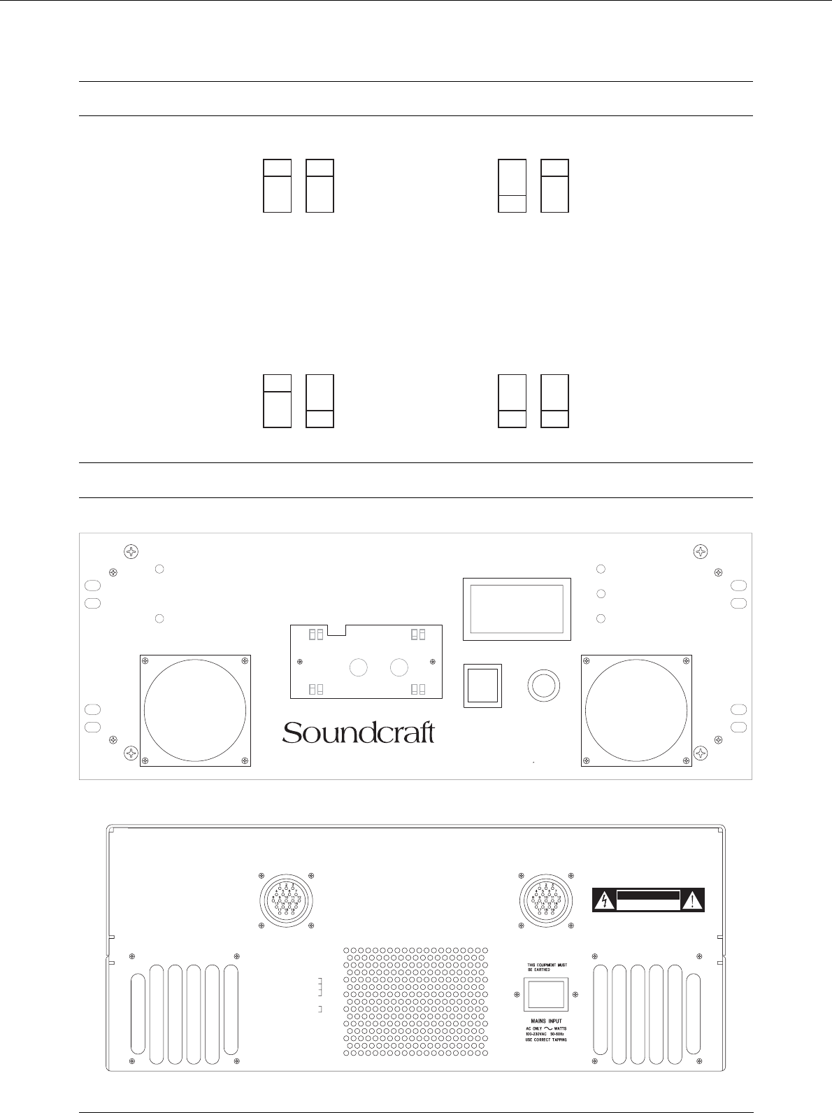
200V
230V
100V
115V
Mains Voltage Selector Positions
CAUTION
RISK OF ELECTRIC SHOCK
DO NOT OPEN
RISK OF ELECTRIC SHOCK
DO NOT OPEN
AVIS: RISQUE DE CHOC ELECTRIQUE
- NE PAS OUVRIR
AVIS: RISQUE DE CHOC ELECTRIQUE
- NE PAS OUVRIR
NO USER SERVICEABLE PARTS INSIDE
NO USER SERVICEABLE PARTS INSIDE
NO USER SERVICEABLE PARTS INSIDE
NO USER SERVICEABLE PARTS INSIDE
PIN 1, 2, 3, 4 +17V 16A
PIN 1, 2, 3, 4 +17V 16A
9, 10, 11, 12 -17V 16A
9, 10, 11, 12 -17V 16A
13 +48V
13 +48V
18 +8V
18 +8V
19
NOT USED
NOT USED
1.25A
5, 6, 7, 8 +0V
5, 6, 7, 8 +0V
16, 17 0V
16, 17 0V
0.5A
14, 15 CHASSIS GROUND
14, 15 CHASSIS GROUND
( BOTH DC CONNECTORS HAVE
IDENTICAL PINOUT )
(BOTH DC CONNECTORS HAVE
IDENTICAL PINOUT )
DC POWER OUT
TO CONSOLE
DC POWER OUT
TO CONSOLE
DC POWER IN
FROM STANDBY SUPPLY
DC POWER IN
FROM STANDBY SUPPLY
TO REDUCE THE RISK
OF FIRE OR ELECTRIC SHOCK
OF FIRE OR ELECTRIC SHOCK
DO NOT EXPOSE THIS UNIT
DO NOT EXPOSE THIS UNIT
TO RAIN OR MOISTURE
DO NOT COVER ANY VENTILATION
DO NOT COVER ANY VENTILATION
SLOTS AS THIS MAY CAUSE THE
SLOTS AS THIS MAY CAUSE THE
EQUIPMENT TO OVERHEAT
EQUIPMENT TO OVERHEAT
WARNING:
MAINS VOLTAGE SELECTION
200V
100V
115V
230V
200V
230V
100V
115V
48V
+
8V
HIGH TEMP
+
17V
CLEAN FAN FILTERS REGULARLY
DO NOT COVER
ANY VENTILATION SLOTS, AS
THIS MAY CAUSE THE EQUIPMENT
TO OVERHEAT
WARNING:
+
17V
-
ACCESS TO MAINS VOLTAGE SELECTION SWITCHES
WARNING: DISPLAY MAINS VOLTAGE SETTING IN
SIDE WINDOW WHEN REFITTING COVER PLATE.
UNDER COVER PLATE.
ENSURE CORRECT MAINS VOLTAGE
SETTING AND CORRECT FUSE BEFORE
CONNECTING MAINS SUPPLY.
DO NOT SWITCH MAINS VOLTAGE SETTINGS
WHILE MAINS SUPPLY IS CONNECTED.
DOTS LIGHT WHEN MAINS LOW
POWER
ON
1
0
OFF
MAINS VOLTAGE
CONSOLE POWER SUPPLY
CPS
2
000
MAINS FUSE:
CAUTION:
ATTENTION:
100V/230V USE T10.0A/250V
TO REDUCE THE RISK OF
AFIN DE REDUIRE LE
RISQUE DE FEU, REMPLACER SEULEMENT
AVEC FUSIBLE DE MEME TYPE.
FIRE, REPLACE WITH SAME
TYPE FUSE ONLY.
Front and Rear Panel Views
4Introduction
OPERATING VOLTAGE RANGE
It is very important to use the correct mains voltage selection. A wide operating range
of mains voltages is provided to enable the unit to function down to only 85Vrms on
the mains supply. This facility is incorporated to overcome the problems that some
power supplies have with internal regulation when operating from a poorly regulated
mains supply.
Do not operate the PSU with a consistently high (above
nominal) reading on the mains meter. Operation with
the mains higher than +10% may cause serious
damage
The mains meter is essentially a peak-reading device, as it is the peak value of the
mains waveform which is the most important factor in providing the correct mains
voltage to the power supply. For this reason, and because with long power cables it
is common for the mains waveform to become distorted, the indication of the meter
may not agree with readings taken with the usual types of quasi-RMS reading
testmeter.
Note that the meter measures the voltage actually available at the PSU, and therefore
will indicate any voltage drop on mains supply wiring.
REPLACING MAINS FUSE.
In the event of incorrect switching of the mains voltage selectors, a mains power surge
or underrated fuse value, the mains fuse in the front panel will blow and the CPS2000
will not function. Switch the ON/OFF switch to the OFF position. Check the fuse
and replace if necessary; also check that the voltage selection is correct for the mains
supply level before switching the unit ON again.
To avoid risk of fire replace only with the correct value
fuse, as indicated on the unit.
In the event of repeated failure of the mains fuse consult the Soundcraft dealer from
where the unit was purchased.
This unit contains no user serviceable parts. Refer all
servicing to a qualified service engineer, through the
appropriate Soundcraft dealer.
Introduction 5

1Soundcraft is a trading division of Harman International Industries Ltd.
End User means the person who first puts the equipment into regular operation.
Dealer means the person other than Soundcraft (if any) from whom the End User
purchased the Equipment, provided such a person is authorised for this purpose by
Soundcraft or its accredited Distributor.
Equipment means the equipment supplied with this manual.
2 If within the period of three years from the date of delivery of the Equipment to the
End User it shall prove defective by reason only of faulty materials and/or
workmanship to such an extent that the effectiveness and/or usability thereof is
materially affected the Equipment or the defective component should be returned to
the Dealer or to Soundcraft and subject to the following conditions the Dealer or
Soundcraft will repair or replace the defective components. Any components
replaced will become the property of Soundcraft.
3 Any Equipment or component returned will be at the risk of the End User whilst in
transit (both to and from the Dealer or Soundcraft) and postage must be prepaid.
4 This warranty shall only be available if:
a) the Equipment has been properly installed in accordance with instructions
contained in Soundcraft’s manual; and
b) the End User has notified Soundcraft or the Dealer within 14 days of the defect
appearing; and
c) no persons other than authorised representatives of Soundcraft or the Dealer have
effected any replacement of parts maintenance adjustments or repairs to the
Equipment; and
d) the End User has used the Equipment only for such purposes as Soundcraft
recommends, with only such operating supplies as meet Soundcraft’s specifications
and otherwise in all respects in accordance Soundcraft’s recommendations.
5 Defects arising as a result of the following are not covered by this Warranty: faulty
or negligent handling, chemical or electro-chemical or electrical influences,
accidental damage, Acts of God, neglect, deficiency in electrical power,
air-conditioning or humidity control.
6. The benefit of this Warranty may not be assigned by the End User.
7. End Users who are consumers should note their rights under this Warranty are in
addition to and do not affect any other rights to which they may be entitled against
the seller of the Equipment.
Warranty
6Introduction

Recommendations for
Installation of the CPS 2000
Installation 7

Recommendations for Installation
The CPS2000 power supply is provided with front panel fixing holes for 19"
rack-mounting and will occupy 4U of rack space. Rear support should be provided
when fitted in a 19" rack.
The CPS2000 is a heavy unit (30kg,) and should be
regarded as a two-man lift. Take suitable precautions
when lifting
As with any power supply that contains a large mains-voltage transformer, it is
preferable to provide a degree of physical isolation of the unit from other electronic
equipment, particularly that which carries low level audio signals, to avoid any
possible hum pick-up. For this reason the unit is used with a long (6.5 metres) output
cable to enable it to be positioned away from the mixing console.
For the same reason, when rack-mounting it is preferable to avoid locating the unit
adjacent to signal processing equipment.
It should be noted that if a complete rack containing a CPS2000 unit is to be operated
from a different mains supply level, then the unit should be withdrawn from the rack
in order to reselect the mains voltage setting, at the same time as resetting any other
equipment.
The other important consideration when rack-mounting the unit is the need for natural
convection of air over the case and an unrestricted air flow through the unit. Note that
air is drawn in at the front of the unit and expelled through the rear panel.
Good ventilation BELOW the unit, in the floor or back of the rack, and similarly
ABOVE the unit, at the top of the rack, will ensure a path for continuous air flow.
Other equipment in the rack which is known NOT to produce a significant amount of
heat should be mounted BELOW the unit. Equipment that also relies on good air flow
within the rack (ie. most power amplifiers and other power supplies) should be given
due consideration and some space should be provided between such units and between
these and the CPS2000 unit. Forced convection, by means of a fan-tray, may be
desirable in this situation.
The CPS2000 will operate as a free-standing unit
without requiring any special cooling arrangement,
but should not be allowed to be accidentally or
deliberately covered over in any way.
Do not operate the unit with the top cover removed as
this exposes hazardous voltages.
The filters on the cooling fans must be inspected
regularly and cleaned if necessary to maintain good
airflow through the unit. This will be particularly
important if the unit is used in a dusty environment.
8Installation

Finally, some consideration should be given to the earthing arrangement of the system
at the centre of which are the console and the CPS2000 (and any other Soundcraft
power supply units). The console chassis is earthed, through the mains earth, via the
power supply. When rack-mounting the CPS2000(and any other Soundcraft power
supply units) care should be taken to avoid any possible ‘ground loops’ in the system
which would introduce audible hum to otherwise clean audio signals. Ground loops
may occur where signal processing equipment, patched to the console, has its signal
earth commoned to the equipment chassis. The ground loop is formed if this chassis
and the power supply chassis are in electrical contact through the fixing rails they
share in the rack. To avoid this situation, standard isolating washers may be employed
when fixing the power supply (or supplies) or any other unit into the rack.
W A R N I N G : THIS APPARATUS MUST BE
EARTHED. Under no circumstances should the mains
earth be disconnected from the CPS2000 power supply
unit.
GENERAL
As with all electrical/electronic equipment care should be taken when handling this
unit. Avoid general mishandling and do not drop. Avoid storage and operation in
dusty locations and do not expose to corrosive atmospheres.
To avoid risk of fire do not expose this unit to rain or
moisture.
Retain all packaging for transportation in the event of the unit requiring servicing.
Retain this manual safely, along with all other relevant documents.
For touring/mobile transportation it is advisable to install the CPS2000 in a flight case
to provide mechanical protection. Refer to your Soundcraft dealer for a suitable case.
Where the CPS2000 is enclosed in a touring case, provision must be made for adequate
ventilation to the rear of the unit to ensure unrestricted supply of air for the cooling
fan.
Use only the 16 Amp mains lead supplied, no other
type is to be used.
Use only the DC output lead supplied, no other type is
to be used.
Installation 9
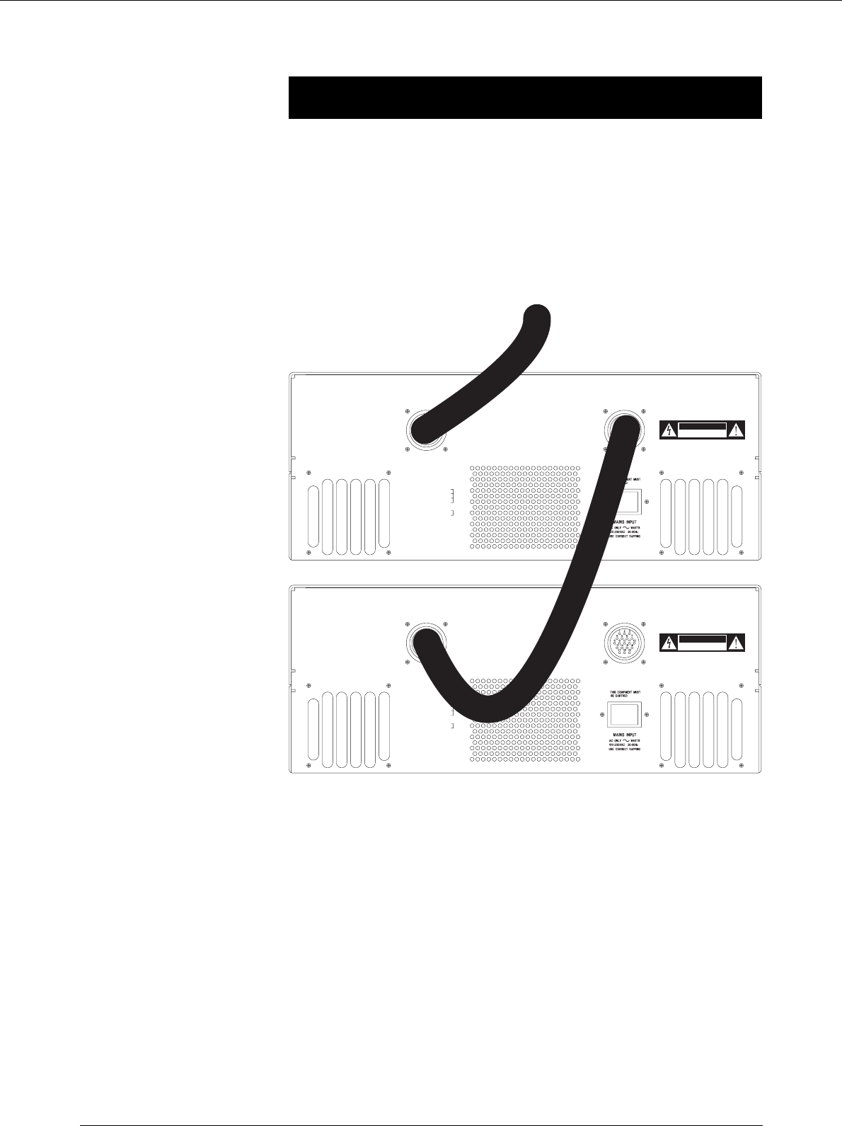
PSU Linking
Link the second PSU to the first as shown in the following diagram.
Note that the linking cable is included when a spare CPS2000 is ordered.
CAUTION
RISK OF ELECTRIC SHOCK
DO NOT OPEN
RISK OF ELECTRIC SHOCK
DO NOT OPEN
AVIS: RISQUE DE CHOC ELECTRIQUE
- NE PAS OUVRIR
AVIS: RISQUE DE CHOC ELECTRIQUE
- NE PAS OUVRIR
NO USER SERVICEABLE PARTS INSIDE
NO USER SERVICEABLE PARTS INSIDE
NO USER SERVICEABLE PARTS INSIDE
NO USER SERVICEABLE PARTS INSIDE
PIN 1, 2, 3, 4 +17V 16A
PIN 1, 2, 3, 4+17V 16A
9, 10, 11, 12 -17V 16A
9, 10, 11, 12 -17V 16A
13 +48V
13 +48V
18 +8V
18 +8V
19 NOT USED
NOT USED
1.25A
5, 6, 7, 8 +0V
5, 6, 7, 8+0V
16, 17 0V
16, 17 0V
0.5A
14, 15 CHASSIS GROUND
14, 15 CHASSIS GROUND
( BOTH DC CONNECTORS HAVE
IDENTICAL PINOUT )
(BOTH DC CONNECTORS HAVE
IDENTICAL PINOUT )
DC POWER OUT
TO CONSOLE
DC POWER OUT
TO CONSOLE
DC POWER IN
FROM STANDBY SUPPLY
DC POWER IN
FROM STANDBY SUPPLY
TO REDUCE THE RISK
OF FIRE OR ELECTRIC SHOCK
OF FIRE OR ELECTRIC SHOCK
DO NOT EXPOSE THIS UNIT
TO RAIN OR MOISTURE
TO RAIN OR MOISTURE
DO NOT COVER ANY VENTILATION
DO NOT COVER ANY VENTILATION
SLOTS AS THIS MAY CAUSE THE
SLOTS AS THIS MAY CAUSE THE
EQUIPMENT TO OVERHEAT
EQUIPMENT TO OVERHEAT
WARNING:
To Console
10 Installation
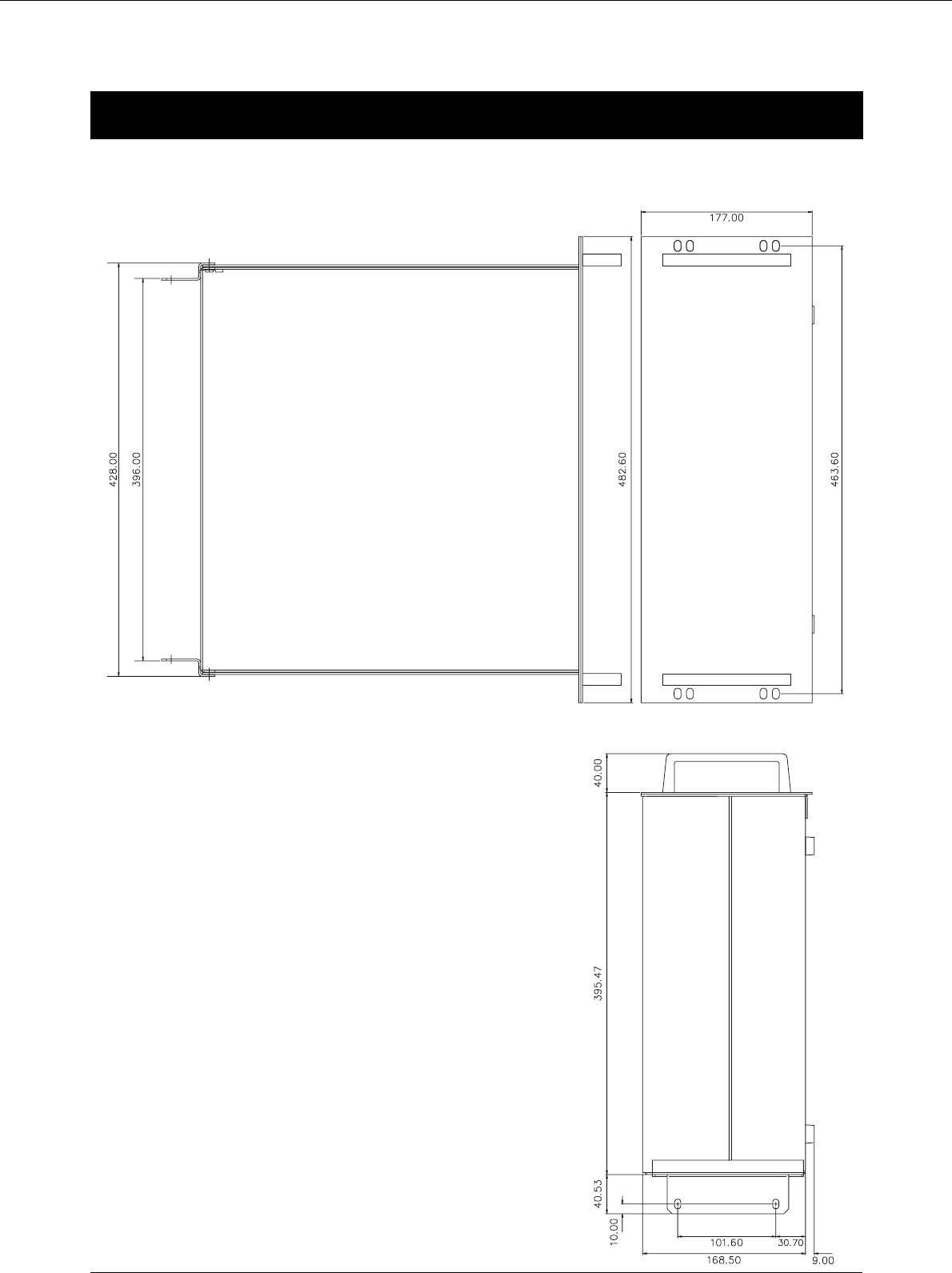
Dimensions
All dimensions in millimeters
Installation 11

12 Installation

Technical Specification
Technical Specification 13

Technical Specification
MAINS INPUT VOLTAGE RANGE:
230/200/115/100 V AC +10% / -15% @ 50/60Hz
RATED INPUT POWER (Max):
980 WATTS
MAINS FUSE RATING:
Use T10AL/250V (slow-blow).
OUTPUTS
DC. VOLTAGE RAIL MAX. OUTPUT CURRENT
+17V 16.00 AMPS
-17V 16.00 AMPS
+48V 0.30 AMPS
+8V 1.25 AMPS
All voltage and current measurements are to be taken
at the console-end of the power supply cable.
OPERATING TEMPERATURE RANGE (Ambient):
-10 TO +40°C.
HUMIDITY:
Similar unit tested at 0-90% RH non-condensing +/-5% Relative Humidity
at 40 °C for 16 hours. Load switched between 20% and 100% at regular
30 minute intervals.
OVERALL DIMENSIONS:
HEIGHT: 177.00mm. (4U)
WIDTH: Chassis 440.00mm.
Front panel 482.60mm.
DEPTH: (excl. handles) 436.00mm.
WEIGHT:
(Excl. packing): 30Kg
14 Technical Specification

Circuit Description
CAUTION:THE FOLLOWING SECTIONS ARE FOR USE
BY QUALIFIED SERVICE PERSONNEL ONLY. TO
REDUCE THE RISK OF ELECTRIC SHOCK, DO NOT
PERFORM ANY SERVICING, OTHER THAN THAT
CONTAINED IN PREVIOUS SECTIONS, UNLESS YOU
ARE QUALIFIED TO DO SO.
Circuit Description 15

Circuit Description
INTRODUCTION.
The CPS2000 power supply provides +/-17V at 16 Amps, +8V at 1.25 Amp, and +48V
at 0.3 Amp. The main PCB (SC3804) is in LH and RH halves. The LH PCB carries
the +17V and +48V supplies. The RH PCB carries the -17V and +8V supplies. A
separate PCB (SC3817) carries the mains voltage selector switches at the front of the
unit.
THE +/- 17V RAILS. SC3804
This consists of two identical +17V supplies connected together to give +/-17V.
Each 17V supply is a linear regulator with conventional fullwave rectification and a
large (100,000uF) reservoir capacitor. This is combined with a second power supply
that powers the driver transistors, the cooling fan, and the digital mains meter. The
main series pass elements are 250W discrete bipolar transistors connected in parallel
with suitable current-sharing precautions and mounted on a fan-cooled heatsink. The
voltage reference and servo control amplifier is provided by a 723 regulator IC. The
circuitry of the +17V regulator is described in detail below:
The +17V Supply. (LH PCB)
The transformer secondary is fused by means of 32 Amp Safeclip (BS88) fuses
mounted in holders on the floor of the chassis. They are NOT intended for customer
replacement. A spare fuse will be provided, but it is stressed that these fuses will only
blow in the event of catastrophic failure, such as a major short in the wiring or a failed
bridge rectifier.
The fullwave bridge rectifier is mounted on the heatsink, at the hottest end as it is the
most heat-tolerant of the semiconductors. The reservoir capacitors are mounted by
clips on the floor of the chassis. For safety reasons, the reservoir capacitor is
discharged by bleeder resistor R9 at switchoff; this takes about 30 seconds. A red
warning LED on the PCB is on whenever the capacitor is charged. The unregulated
DC is approx +26 to +29V.
The 723 IC contains a 7.15V nominal Zener diode, defining the voltage that appears
at Pin 6. Zener references generate appreciable noise, and this, plus any ripple, is
filtered out by R10,C10. R10 is in series with the positive input of the servo opamp
(Pin 5) and is made roughly equal in resistance to the feedback divider R16,17 etc to
minimise bias-current offsets.
The feedback divider R16,17,18 & PR1 derives a fraction of the output voltage and
delivers it to the negative input of the servo opamp. (Pin 4) The negative feedback
keeps this point also at 17.15V, so the actual output voltage is determined by the
feedback divider ratio, which is trimmed over a narrow range by PR3.
The output of the servo opamp controls the output through TR8, which is an emitter
follower driving the parallel pass devices TR4,5,6. R41 is included for diagnostic
purposes, so that the current being supplied by the 723 (only a few mA) can be
measured. The power supply to TR8 is taken from the +12V supply. This has its 0V
side connected to the positive unregulated DC supply of 26 - 29V, (at nominal mains)
giving a total voltage of approx 38 - 41V for the driver; this also powers the 723 IC.
This subrail markedly reduces the minimum drop across the pass elements and
therefore increases the efficiency.
16 Circuit Description

The 723 IC is powered through R11, which allows ripple filtering by C9, and voltage
protection by DZ1,2. These Zeners are not required to reduce ripple; their function is
purely protective, preventing the 40V Vmax spec of the 723 being exceeded should
the mains voltage rise above nominal.
The current through the pass devices TR4-7 is shared equally due to the
current-sharing resistors R35-45. The drop across these at full load is approx 200mV
which is more than enough to swamp Vbe differences in the main transistors.
50 Amp Schottky diode D7 on the output allows supplies to be paralleled for
redundancy.
The Mains Voltage Meter.
The incoming mains voltage is continuously indicated on the front panel by a 3.5 Digit
Panel Meter. (DPM) This is powered from a +5V supply derived from the +12V subrail
by 7805 regulator REG2.
The +5V supply is reduced to +2.5V by R30,31, and buffered by IC2-A to generate a
half-rail for the DPM input.
The incoming mains is monitored by differential amplifier IC1-A, which looks at the
voltage between Live and Neutral; this avoids problems with having one side of the
meter connected to Earth, which is often not at quite the same potential as Neutral.
The Voltage is picked off via two special BSI safety-approved 680K resistors on the
voltage select PCB (SC3817) which connect to CN3. The circuitry around IC1-A
(R21-24) gives unity gain, but the presence of the 680K resistors on the input gives
suitable scaling of the 50Hz signal.
The signal is applied to precision full-wave rectifier IC1-B, IC2-B via DC-blocking
cap C5; this circuit is biased by the +2.5V halfrail. The rectified output is smoothed
by C6 and scaled by R39 and PR1 before applying it to the DPM input on CN1 Pin
8. (IN HI)
Note the DPM has a differential input, so the cold side (IN LO, Pin 7) is connected to
the +2.5V halfrail.
The Mutual Shutdown System.
Equipment containing some kinds of op-amp is vulnerable to damage when only one
of the +/-17V rails fails, as in this case excessive supply currents can be drawn,
damaging fuse resistors on the modules.
When both 17V supplies are working normally, current flows through DZ8, OPTO1,
and across to the RH PCB. OPTO1 is on so the base drive to TR22 is shunted away
and the 723 works normally. Likewise, TR24 is kept on via R100, and ensures TR28
stays off.
If either supply fails there is insufficent voltage to keep DZ8 conducting, and current
flow ceases in the mutual shutdown line. TR22 is turned via the special supply
generated by D13, C26, and the internal node of the 723 IC3 is pulled down to ground,
turning it off. Likewise, in the -17V supply, TR28 is turned via the special supply
generated by D14, C25, and the internal node of IC4 is pulled down to ground, turning
it off.
C27,30 delay the action of mutual shutdown sufficiently to allow the supplies to start,
as they may not rise to working voltage at exactly the same rate.
Circuit Description 17

When shutdown has ocurred, the supply is reset by turning the mains briefly off and
on. R100 discharges C25 so that the circuit is ready for use at the next switch-on. The
special supplies generated by D13, C26, and D14, C25, are designed to discharge very
quickly at power-off, and it should not be necessary to turn the PSU off for more than
a second to reset it.
Overcurrent Protection.
The simplest form of overcurrent protection is the constant-current system; when an
attempt is made to draw excessive current, the output voltage is reduced so that no
more than a fixed maximum can be drawn. The high current capability of this PSU
means that constant current protection alone is not practical as the dissipation in the
pass devices is too high for the cooling system to deal with, and in the long term they
will overheat.
The standard answer to this problem is foldback current-limiting. Once again the
output voltage is reduced to prevent excessive current flow, but it is more severely
reduced so that the current flowing is not limited to a fixed maximum, but to a value
lower than that which triggered the protection originally. This greatly reduces the
dissipation in the supply in protection mode.
This system accomplishes its task, but can give trouble as the supply may work
perfectly into a resistive test load but not start into a real console load. The problem
is that a mixing console is essentially a constant-current load; as the supply voltage is
increased, almost the full current is drawn when only 2 or 3 volts are applied. There
are thus two stable states, with rails normal and the full current drawn, or with the
supply shut down to the few volts that will cause the foldback current to flow. When
the supply is switched on, it tends to stick in the second of these two states.
The CPS2000 avoids this problem by implementing constant-current protection that
causes complete shutdown (rather than foldback) after a fixed time delay. This is
described for the +17V supply; the -17V supply operates identically.
The first part of the problem is to measure the output current without dropping 0.6V
across a resistor to turn on a protection transistor. At 16 Amps the losses in this drop
would be unacceptable. Therefore supply current is measured by the voltage drop
across 0.05R resistors (R35,36 in parallel) which carry a quarter of the output current
and so drop 200 mV at full load. This is compared with a 200mV reference voltage
across R86, derived from bands-gap reference IC8 which sits on the output rail, by
differential amplifier TR18,19. When the input to TR19 exceeds the 200mV applied
to TR18, TR19 conducts and pulls down the internal 723 node at pin 13, reducing the
output voltage.
This causes current to cease in the mutual shutdown line, as described above, and after
a brief delay caused by C27,30, both 17V supplies are shut down.
ISSUE 8 operates exactly as above. The only difference is that the differential
amplifier TR18,19 has its tail fed from a negative subrail at approx -26V. This subrail
is generated from the AC input to the PCB by charge-pump C41,42,D22,23. The
resulting negative voltage is stabilised by 8V2 Zener DZ10, and applied to R73. This
keeps the tail current of TR18,19 more constant, and so maintains the
transconductance (current out for voltage in) at a higher level, giving closer feedback
control of current-limiting under extreme conditions. The RH PCB operates
identically.
18 Circuit Description

Undervoltage warning.
The supply gives a warning indication when the mains voltage has fallen so low that
regulation is about to be lost. The Headroom Indicator subsystem illuminates all the
decimal points on the DPM, giving a clear signal that something is amiss.
The voltage across the pass transistors is monitored by TR3; when this voltage falls
too low, TR3 turns off, turning off TR1. TR1 collector is then pulled up to +40V by
R26, charging C7 through D5, and so turning on TR2. This connects the DPM decimal
point connections to the local 0V (actually +26 TO +29V above supply 0V) via
current-limiting resistors R32-34. The peak-hold action of D5/C7 is required as the
voltage across the pass transistors includes a large ripple content that would leave the
decimal points rather dim if they were being strobed at 100 Hz.
An identical circuit (TR9, TR10) monitors headroom in the -17V supply. The voltage
across the pass transistors is monitored by TR10. When this voltage falls too low,
TR10 turns off, turning off TR9. TR9 collector is connected to the LH PCB via
connectors CN8-CN7, and the cessation of current drawn indicates low headroom. On
the LH PCB, when this current ceases D12 anode is pulled high by R78, and TR2
turns on, illuminating the decimal points on the meter.
The -17V Supply. (RH PCB)
The actual 17V section of this is identical to that in the +17V section.
The +12V subrail circuitry is much simpler as it only provides power for the driver
TR11, the 723, and the fan. There is no mains meter circuitry here.
The Temperature Protection System.
This is designed to protect the +/-17V rails only. The +48V and +8V regulators
incorporate internal thermal protection, and in any case, their heat dissipation is very
small compared with the heatsink size. The +/-17V rails, however are vulnerable to
blocked cooling vents or fan failure, so protection is provided that shuts down the 17V
rails if the TO3 device cans exceed 100 degC.
The thermal sensor on the RH heatsink is LM35DZ TR31. It outputs 10mV per
degreeC above freezing point (0 degC) and applies it to IC5-B non-inverting input.
IC5-B is used as a comparator, with R114,106 giving a small amount of hysteresis to
prevent dither or oscillation.
IC reference TR29 produces a stable 1.237V which is reduced to 1.00V by R104,112.
This is applied to the inverting inputs of IC5-A,B as the shutdown temperature
reference, and represents 90 degC at the TO3 can top*. TR27 senses the temperature
of the LH heatsink.
* Temperature shutdown takes place at 100 degC on some earlier issue PCB’s.
If either heat sensor exceeds 100 degC the output of the associated op-amp goes high,
applying voltage to the top of R109, and enabling the relaxation LED-flashing
oscillator IC6-B. LED7 flashes at approx 2 Hz.
If JMP2 is fitted in the "ON" position, shutdown of the +/-17V rails is also
implemented. TR30 is turned on via R117, which turns on TR28, and shuts down the
-17V supply. The mutual shutdown system then also shuts down +17V. If JMP2 is in
the "OFF" position, only the LED flashing occurs.
Circuit Description 19

The +48V Supply.
Max current rating is 0.3 Amps. The +48V phantom supply is based on the
high-voltage regulator TL783C. (REG1) The AC input is fused by F4 and fullwave
rectified by BR4; C1,24 are the reservoir capacitors. The unregulated DC may rise as
high as +85V on high mains.
The TL783C maintains a fixed 1.27 V between its ADJ and OUT pins, so the
adjustable voltage-divider R1-PR2-R2 gives an output of approx 48V. This can be
finely adjusted by PR2. The divider current is also used to power the rail indicator
LED3, minimising the current wasted inside the regulator circuit.
An output current of 0.5A and a wide (+10/-20%) mains range means that a TL783C
alone is only marginally capable of handling the power dissipation. Therefore
preregulator TR16,17, working as an emitter-follower biased from the +48V output
by zener DZ5, absorbs some of the voltage drop, so that only approx 62V appears on
the TL783C input. C28 ensures HF stability of REG1.
Two protection diodes are included. D1 protects the regulator from reverse voltage if
there is a charged capacitor across the output but the voltage on C1,24 has collapsed.
D2 prevents the ADJ pin from rising above the OUT pin (due to the charge on C2) if
the output is shorted.
Conventional diode D6 on the output allows supplies to be paralleled for redundancy.
The +8V Supply.
Max current rating 1.25 Amps. This supply is primarily intended for powering console
internal computers; it will be regulated down to +5V inside the console.
The AC input is fused by F4 and fullwave rectified by BR4. The unregulated DC is
about +15V on nominal mains. The LM317T regulator maintains a fixed 1.25V
between its ADJ and OUT pins, so fixed voltage-divider R68,69 gives an output of
approx 8.4 V. C23 reduces output ripple from 1 mV to approx 180 uV at full load.
Two protection diodes are included. D9 protects the regulator from reverse voltage if
there is a charged capacitor across the output but the voltage on C20,21 has collapsed.
D10 prevents the ADJ pin from rising above the OUT pin (due to the charge on C23)
if the output is shorted.
Conventional diode D11 on the output allows supplies to be paralleled for redundancy.
Mains Voltage Select PCB. SC3817
This PCB (SC3817) carries the inrush suppressor and two DPCO switches that select
the transformer primary connections to suit the incoming mains voltage.
The first switch A selects between EUROPE and USA/JAPAN settings. The second
switch B selects high and low variations on this:
Mains Mains Nominal Dropout Dropout
Switch A Switch B Mains Voltage Voltage
20 Circuit Description

Setting Setting Voltage Spec’d Measured
EUROPE 230/115 230 195 186
EUROPE 200/100 200 170 164
USA/JAPN 230/115 115 98 95
USA/JAPN 200/100 100 85 85
Note that the dropout voltages in the rightmost column were measured on a CPS2000,
and are significantly lower than the guaranteed dropout specification of -15%.
Fan Control PCB. SC4032.
Thermostatic fan control was fitted to the CPS2000 from February 1999. The
controller is a separate PCB (SC4032) mounted on the front heatsink bracket, with a
thermal sensor pressed against the top surface of the heatsink.
The CPS2000 fan control system adapts the fan speed to the power drawn. This gives
a substantial reduction in fan noise under almost all circumstances; the exception being
10% high mains and maximum current drawn, which naturally sets the fan to full
speed. The PCB (with associated mounting bracket) may be retrofitted to existing
CPS2000 units.
The servo circuit consists of opamp IC1-A, temperature sensor IC5, shunt regulator
IC4, and fan control devices TR7,TR10.
IC4 maintains 2.50V between its "anode" and "cathode"; this is the precise voltage
that drives the reference chain R53,55. TR8 also uses this voltage to set its emitter at
4.4V above ground; this keeps IC1’s inputs within their common-mode range. Thus
both ends of the voltage divider R53-R55 are fixed at defined voltages.
LM35DZ temperature sensor IC5 outputs 10mV per degreeC above freezing point (0
degC) and applies it to IC1-A non-inverting input. The desired heatsink temperature
is set at the junction of R53,55, which sits at +5.0V approx. This is 600mV above the
+4.4V rail, and so represents 60 degC.
R52,57 set the servo loop gain. This is designed to be safely below the level at which
slow thermal oscillations would occur. R56,D19 increase the loop gain when IC1-A
output is below 4V. This prevents the fan sitting for long periods in a not-quite-running
state where it consumes current but does not rotate. The voltage range 1-4V where
this occurs is thus skipped over quickly.
The fan is driven through feedback amplifier TR7,10, which has a voltage gain of 1.3
times. This allows the fan to be driven over its full operating voltage range despite the
output saturation limits of IC1-A. This gives improved cooling at high temperatures
and mains voltages.
The CPS2000 thermal shutdown system is quite separate and has no connection with
this PCB.
Circuit Description 21

FAULTFINDING NOTES.
SAFETY: These safety notes are directed to those
testing and repairing this power supply. Legal
requirements mean that we must not encourage
untrained personnel to take the lid off.
+/- 17V RAILS.
1) A convenient position for attaching a test meter to 0V is the top leg of bleeder
resistor R9 (top leg of R47 on RH PCB) Remember these resistors run hot.
2) If one side of the +/-17V supply is not working, the mutual shutdown system will
close down both sides of the supply. This makes faultfinding difficult as it is often not
obvious which side has failed. The mutual shutdown can be disabled by putting on
jumpers JMP1 & JMP3 on PCBs at Issue 6 and above.
IT IS ESSENTIAL THAT THESE JUMPERS ARE
REMOVED AFTER SERVICING IS COMPLETED!
FAILURE TO DO THIS MAY CAUSE SEVERE CONSOLE
DAMAGE IF ONLY ONE 17V RAIL SHUTS DOWN.
3) If the wireform connecting the two PCBs is disconnected, the mutual shutdown
will close down both sides of the supply. The Headroom Alarm dots will also show
on the DPM as an active low from the RH PCB is required to suppress them, and this
is now missing.
4) If there is no power to the 723 IC (eg if R11 or R48 is open-circuit) the output will
remain low, but no damage occurs.
5) It is possible to swop over the two 2-pin connections on the LH PCB in error. The
fan will not run, but no circuit damage occurs.
+48V SUPPLY.
1) If TR17 fails short-circuit, the regulator will appear to work, but since all voltage
is dropped across the TL783 regulator, this will overheat and shut down at high
currents. The TL783 should not be damaged if this is the only fault present.
2) If zener DZ5 fails short-circuit, the regulator will not turn on, and there will be
only 300 mV approx at the output.
3) As usual, the unregulated supply to the +48V regulator can reach +90V, and should
be treated with some respect.
+8V SUPPLY.
1) This is a completely standard IC regulator circuit. The regulator REG3 is the only
part that is likely to fail.
2) This supply contains mains voltages on the voltage select PCB, the mains switch,
etc, and the usual precautions must be taken.
3) The main reservoir capacitors have a capacity of one tenth of a Farad, and are
charged to +26V.
22 Circuit Description

THIS IS DANGEROUS.
The danger lies not in the voltage, but in the enormous currents that will flow if the
capacitor terminals are shorted. A small screwdriver will simply disappear in a violent
explosion. The main bodily danger is from metal watchstraps, etc. Serious burns are
very likely if these contact the capacitor.
For safety reasons, the reservoir capacitors are discharged at switchoff by bleeder
resistors R9 and R47; this takes about 30 seconds. Red warning LEDs on the PCB are
ON when the capacitors are charged.
Fuse Replacement
The 32A fuses mounted on either side of the transformer must be replaced with
identical parts only. Soundcraft part number ZD8900.
F1, located on the voltage selector PCB, must be replaced with an identical part.
Soundcraft part number ZD8112.
Circuit Description 23

24 Circuit Description

Parts List
Parts List 25

Spare Parts
Notes:
1) The ‘Module/PCB Assemblies’ section is indented to show those items which are part of another, higher level, item.
2) Some of the descriptions are preceded by one of the following 3 symbols:
# - STATIC SENSITIVE. Anti-static precautions must be taken whilst handling this part.
! - SAFETY CRITICAL PART. A part of a different type may not be substituted.
@ - A part from a specific Manufacturer. Using an equivalent from another manufacturer may lead to loss of performance.
Top-Level Structures
CPS2000 POWER SUPPLY RW8009
Description . . . . . . . . . . . . . . . . . . . . . Part Number
!CPS2000 WIRED TESTED PSU CHAS . . . . . . . . RY8009
!5X20MM T2A/250V AS FUSE . . . . . . . . . . . ZD8102
!5X20MM T10A/250V AS FUSE . . . . . . . . . . ZD8110
!5X20MM T12.5A/250V AS FUSE . . . . . . . . . . ZD8112
!CPS2000 FUSE 32A BS88 . . . . . . . . . . . . ZD8900
CPS2000 USER&TECH GUIDE . . . . . . . . . . ZM0198
26 Parts List

MAIN ASSEMBLIES
! CPS2000 WIRED TESTED PSU CHAS RY8009
Ident . . . . . . . . . . . . . . . . . . . . . . . . . . Description . . . . . . . . . . . . . . . . . Part Number
—- . . . . . . . . . . . . . . . . . . . . . . . . . . . . 80MM FAN FILTER ASSY . . . . . . . . HZ2211
—- . . . . . . . . . . . . . . . . . . . . . . . . . . . . CPS2000 PSU CVR PLATE . . . . . . . PB0720-02
—- . . . . . . . . . . . . . . . . . . . . . . . . . . . . CPS2000 LID . . . . . . . . . . . PH1402-03
—- . . . . . . . . . . . . . . . . . . . . . . . . . . . . CPS2000 FRONT PNL . . . . . . . . PJ1508-04
—- . . . . . . . . . . . . . . . . . . . . . . . . . . . . CPS2000 WIRED CHASSIS ASSY . . . . . RS5978
. . . . . . . . . . . . . . . . . . . . . . . . . . . . . CPS2000 TEMP SENSOR WFM. . . . . . . . RV3952
CPS2000 WIRED CHASSIS ASSY RS5978
Ident . . . . . . . . . . . . . . . . . . . . . . . . . . Description . . . . . . . . . . . . . . . . . Part Number
—- . . . . . . . . . . . . . . . . . . . . . . . . . . . . CPS2000 PSU TRANS CLAMP PLATE . . . . PF0646-01
—- . . . . . . . . . . . . . . . . . . . . . . . . . . . . CPS2000 TX GUARD PLATE . . . . . . PK2563-01
—- . . . . . . . . . . . . . . . . . . . . . . . . . . . . CPS2000 LH MODULE ASSY . . . . . . RS5974
—- . . . . . . . . . . . . . . . . . . . . . . . . . . . . CPS2000 RH MODULE ASSY . . . . . . RS5975
—- . . . . . . . . . . . . . . . . . . . . . . . . . . . . CPS2000 FRONT SUB PNL ASSY . . . . . RS5976
—- . . . . . . . . . . . . . . . . . . . . . . . . . . . . CPS2000 CHASSIS ASSY . . . . . . . RS5977
pcb . . . . . . . . . . . . . . . . . . . . . . . . . . . CPS2000 STAR POINT PCB . . . . . . . SC4066-01
W/Form . . . . . . . . . . . . . . . . . . . . . . . . CPS2000 TX WFM ASSY . . . . . . . . RV3656
W/Form . . . . . . . . . . . . . . . . . . . . . . . . CPS2000 MNS INLT TO MNS SWT WM. . . . RV3657
W/Form . . . . . . . . . . . . . . . . . . . . . . . . CPS2000 MNS TO VOL SEL PCB WFM . . . RV3659
W/Form . . . . . . . . . . . . . . . . . . . . . . . . CPS2000 MAINS METER WFM . . . . . . RV3660
W/Form . . . . . . . . . . . . . . . . . . . . . . . . CPS2000 LH/RH PCB LINKING WFM . . . . RV3661
W/Form . . . . . . . . . . . . . . . . . . . . . . . . CPS2000 DC OUTPUT WFM . . . . . . RV3662
W/Form . . . . . . . . . . . . . . . . . . . . . . . . CPS2000 OV LINK WFM . . . . . . . . RV3663
W/Form . . . . . . . . . . . . . . . . . . . . . . . . CPS2000 RESERVR CAP TO PCB WFM . . . RV3664
W/Form . . . . . . . . . . . . . . . . . . . . . . . . CHASSIS EARTH WFM 600MM . . . . . RV3695-600
CPS2000 LH MODULE ASSY RS5974
Ident . . . . . . . . . . . . . . . . . . . . . . . . . . Description . . . . . . . . . . . . . . . . . Part Number
—- . . . . . . . . . . . . . . . . . . . . . . . . . . . . 2WY MTHD .1" FML . . . . . . . . . FF0585
—- . . . . . . . . . . . . . . . . . . . . . . . . . . . . PAPST 12V 2.4W 80MM FAN . . . . . . . HD0005
—- . . . . . . . . . . . . . . . . . . . . . . . . . . . . CPS2000 EXTRUDED HEATSINK . . . . . PN1260-03
—- . . . . . . . . . . . . . . . . . . . . . . . . . . . . CPS2000 PSU PCB ASSY . . . . . . . RI3804 or RJ3804
—- . . . . . . . . . . . . . . . . . . . . . . . . . . . . 30CMX30CM THERMALLY CNDCTV SHT . . ZC0223
—- . . . . . . . . . . . . . . . . . . . . . . . . . . . . TO-220 SIL PAD SELF ADHESIVE . . . . . ZC0250
—- . . . . . . . . . . . . . . . . . . . . . . . . . . . . SIL PAD 900 .009"THK ADH BACKE . . . . . ZC0251
—- . . . . . . . . . . . . . . . . . . . . . . . . . . . . TO3 INSULATING WASHER . . . . . . . ZC10029
D7 (on SC3804-09) . . . . . . . . . . . . . . . . . DIODE MBR5025L 50A 25V SCK . . . . . . BA0023
D7 (on SC3804-10) . . . . . . . . . . . . . . . . . . . DIODE MBR6045WT. . . . . . . . . . . . . . BA10018
REG1 . . . . . . . . . . . . . . . . . . . . . . . . . VOLTAGE REG TL783CKC . . . . . . . BE0455
REG2 . . . . . . . . . . . . . . . . . . . . . . . . . V.REG LM7805 +5V 1A . . . . . . . . . BE0424
TR4 . . . . . . . . . . . . . . . . . . . . . . . . . . MJ15024 NPN POWER TRANS TO3 . . . . . BD0373
TR5 . . . . . . . . . . . . . . . . . . . . . . . . . . MJ15024 NPN POWER TRANS TO3 . . . . . BD0373
TR6 . . . . . . . . . . . . . . . . . . . . . . . . . . MJ15024 NPN POWER TRANS TO3 . . . . . BD0373
TR7 . . . . . . . . . . . . . . . . . . . . . . . . . . MJ15024 NPN POWER TRANS TO3 . . . . . BD0373
TR8 . . . . . . . . . . . . . . . . . . . . . . . . . . MJL3281A DRIVER TRANSISTOR . . . . . BD0399
TR17 . . . . . . . . . . . . . . . . . . . . . . . . . MJL3281A DRIVER TRANSISTOR . . . . . BD0399
W/Form . . . . . . . . . . . . . . . . . . . . . . . . LINK WFM(FREE ENDS)100MM . . . . . RV4084-100
pcb ass . . . . . . . . . . . . . . . . . . . . . . . . . CPS2000 FAN CONTROL PCB ASSY . . . . RA4032
Parts List 27

CPS2000 RH MODULE ASSY RS5975
Ident . . . . . . . . . . . . . . . . . . . . . . . . . . Description . . . . . . . . . . . . . . . . . Part Number
—- . . . . . . . . . . . . . . . . . . . . . . . . . . . . 2WY MTHD .1" FML . . . . . . . . . FF0585
—- . . . . . . . . . . . . . . . . . . . . . . . . . . . . PAPST 12V 2.4W 80MM FAN . . . . . . . HD0005
—- . . . . . . . . . . . . . . . . . . . . . . . . . . . . CPS2000 EXTRUDED HEATSINK . . . . . PN1260-03
—- . . . . . . . . . . . . . . . . . . . . . . . . . . . . CPS2000 PSU PCB ASSY . . . . . . . RI3804 or RJ3804
—- . . . . . . . . . . . . . . . . . . . . . . . . . . . . 30CMX30CM THERMALLY CNDCTV SHT . . ZC0223
—- . . . . . . . . . . . . . . . . . . . . . . . . . . . . TO-220 SIL PAD SELF ADHESIVE . . . . . ZC0250
—- . . . . . . . . . . . . . . . . . . . . . . . . . . . . SIL PAD 900 .009"THK ADH BACKE . . . . . ZC0251
—- . . . . . . . . . . . . . . . . . . . . . . . . . . . . TO3 INSULATING WASHER . . . . . . . ZC10029
D8 (on SC3804-09) . . . . . . . . . . . . . . . . . DIODE MBR5025L 50A 25V SCK . . . . . . BA0023
D8 (on SC3804-10) . . . . . . . . . . . . . . . . . . . DIODE MBR6045WT. . . . . . . . . . . . . . BA10018
REG3 . . . . . . . . . . . . . . . . . . . . . . . . . V.REG +1.2/37V 1.5A (LM317T) . . . . . . . BE0430
TR11 . . . . . . . . . . . . . . . . . . . . . . . . . MJL3281A DRIVER TRANSISTOR . . . . . BD0399
TR12 . . . . . . . . . . . . . . . . . . . . . . . . . MJ15024 NPN POWER TRANS TO3 . . . . . BD0373
TR13 . . . . . . . . . . . . . . . . . . . . . . . . . MJ15024 NPN POWER TRANS TO3 . . . . . BD0373
TR14 . . . . . . . . . . . . . . . . . . . . . . . . . MJ15024 NPN POWER TRANS TO3 . . . . . BD0373
TR15 . . . . . . . . . . . . . . . . . . . . . . . . . MJ15024 NPN POWER TRANS TO3 . . . . . BD0373
W/Form . . . . . . . . . . . . . . . . . . . . . . . . LINK WFM(FREE ENDS)100MM . . . . . RV4084-100
pcb ass . . . . . . . . . . . . . . . . . . . . . . . . . CPS2000 FAN CONTROL PCB ASSY . . . . RA4032
CPS2000 FRONT SUB PNL ASSY RS5976
Ident . . . . . . . . . . . . . . . . . . . . . . . . . . Description . . . . . . . . . . . . . . . . . Part Number
—- . . . . . . . . . . . . . . . . . . . . . . . . . . . . ! C1350AA HIGH INRUSH NON ILLUM . . . . DL8003
—- . . . . . . . . . . . . . . . . . . . . . . . . . . . . LED 3.5DIGIT PANEL METER . . . . . . . JE0418
—- . . . . . . . . . . . . . . . . . . . . . . . . . . . . CPS2000 FRONT SUB-PNL . . . . . . . PF0648-04
—- . . . . . . . . . . . . . . . . . . . . . . . . . . . . CPS2000 MTR BRKT . . . . . . . . . PF0653-02
—- . . . . . . . . . . . . . . . . . . . . . . . . . . . . ! SCHRTR FUSEHOLDER . . . . . . . ZD8014
—- . . . . . . . . . . . . . . . . . . . . . . . . . . . . ! SCHRTR FUSE CARRIER . . . . . . . ZD8015
—- . . . . . . . . . . . . . . . . . . . . . . . . . . . . ! SCHRTR FUSEHOLDER INSULATOR . . . ZD8016
—- . . . . . . . . . . . . . . . . . . . . . . . . . . . . ! 5X20MM T10A/250V AS FUSE . . . . . . ZD8110
W/Form . . . . . . . . . . . . . . . . . . . . . . . . CPS2000 MNS SWT TO VOLT SEL WM . . . RV3658
pcb ass . . . . . . . . . . . . . . . . . . . . . . . . . CPS2000 VOLTAGE SEL PCB ASSY . . . . RD3817
CPS2000 CHASSIS ASSY RS5977
Ident . . . . . . . . . . . . . . . . . . . . . . . . . . Description . . . . . . . . . . . . . . . . . Part Number
—- . . . . . . . . . . . . . . . . . . . . . . . . . . . . CAP ELEC VERT 10,000UF 40V DC . . . . . CE0507
—- . . . . . . . . . . . . . . . . . . . . . . . . . . . . ! IEC INLET SKT 16A PNL MNT . . . . . . FJ8010
—- . . . . . . . . . . . . . . . . . . . . . . . . . . . . CPS2000 REAR LH BRACKET . . . . . . PG1301-01
—- . . . . . . . . . . . . . . . . . . . . . . . . . . . . CPS2000 REAR RH BRACKET . . . . . . PG1302-01
—- . . . . . . . . . . . . . . . . . . . . . . . . . . . . CPS2000 BASE PANEL . . . . . . . . PJ1507-04
—- . . . . . . . . . . . . . . . . . . . . . . . . . . . . PSU EARTH SYMBOL SLF-ADH . . . . . ZA0078
28 Parts List

PCBS
CPS2000 FAN CONTROL PCB ASSY RA4032
Ident . . . . . . . . . . . . . . . . . . . . . . . . . . Description . . . . . . . . . . . . . . . . . Part Number
—- . . . . . . . . . . . . . . . . . . . . . . . . . . . . CPS2000 HEATSINK BRACKET . . . . . PF0655-02
—- . . . . . . . . . . . . . . . . . . . . . . . . . . . . TO-220 SIL PAD SELF ADHESIVE . . . . . ZC0250
pcb . . . . . . . . . . . . . . . . . . . . . . . . . . . CPS2000 FAN CONTROL PCB . . . . . . SC4032-01
C1 . . . . . . . . . . . . . . . . . . . . . . . . . . POLY-CAP 5MM 5% 63V 100N . . . . . . CC0252
CN1 . . . . . . . . . . . . . . . . . . . . . . . . . . 2WY MTHD.1"R/A LCKG ML HDR S12 . . . . FF0648
D19 . . . . . . . . . . . . . . . . . . . . . . . . . . DIODE 1N4148 . . . . . . . . . . . BA0001
IC1 . . . . . . . . . . . . . . . . . . . . . . . . . . JRC DUAL OP AMP 072BDE . . . . . . BE0413
IC4 . . . . . . . . . . . . . . . . . . . . . . . . . . TL431 SHUNT REGULATOR . . . . . . BE0503
IC5 . . . . . . . . . . . . . . . . . . . . . . . . . . LM35DZ THERMAL SENSOR . . . . . . BE0477
P1 . . . . . . . . . . . . . . . . . . . . . . . . . . CPS2000 FAN CONTROL WFM . . . . . RV4016-140
P2 . . . . . . . . . . . . . . . . . . . . . . . . . . CPS2000 FAN CONTROL WFM . . . . . RV4016-140
R32 . . . . . . . . . . . . . . . . . . . . . . . . . . MF 0.25W RES 1% 680R BL . . . . . . . AP1345
R33 . . . . . . . . . . . . . . . . . . . . . . . . . . MF 0.25W RES 1% 9K1 BL . . . . . . . AP1372
R35 . . . . . . . . . . . . . . . . . . . . . . . . . . MF 0.25W RES 1% 10K BL . . . . . . . AP1373
R36 . . . . . . . . . . . . . . . . . . . . . . . . . . MF 0.25W RES 1% 390R BL . . . . . . . AP1339
R38 . . . . . . . . . . . . . . . . . . . . . . . . . . MF 0.25W RES 1% 120R BL . . . . . . . AP1327
R52 . . . . . . . . . . . . . . . . . . . . . . . . . . MF 0.25W RES 1% 4K7 BL . . . . . . . AP1365
R53 . . . . . . . . . . . . . . . . . . . . . . . . . . MF 0.25W RES 1% 3K9 BL . . . . . . . AP1363
R55 . . . . . . . . . . . . . . . . . . . . . . . . . . AP 0.25W RES 1% 1K BL . . . . . . . . AP1349
R56 . . . . . . . . . . . . . . . . . . . . . . . . . . MF 0.25W RES 1% 100K BL . . . . . . . AP1397
R57 . . . . . . . . . . . . . . . . . . . . . . . . . . MF 0.25W RES 1% 1M BL . . . . . . . . AP1421
R58 . . . . . . . . . . . . . . . . . . . . . . . . . . MF 0.25W RES 1% 10K BL . . . . . . . AP1373
TR7 . . . . . . . . . . . . . . . . . . . . . . . . . . NPN TRANS 2SC2240BL(TAPED) . . . . . BD0302
TR8 . . . . . . . . . . . . . . . . . . . . . . . . . . PNP TRANS 2SA970GR (TAPED)TOSH . . . BD0301
TR10 . . . . . . . . . . . . . . . . . . . . . . . . . BD680 TRANS . . . . . . . . . . BD0368
TR10 . . . . . . . . . . . . . . . . . . . . . . . . . TO126 CLIP-ON H/SNK RDPT PF730. . . . . PN1235
CPS2000 VOLTAGE SEL PCB ASSY RD3817
Ident . . . . . . . . . . . . . . . . . . . . . . . . . . Description . . . . . . . . . . . . . . . . . Part Number
—- . . . . . . . . . . . . . . . . . . . . . . . . . . . . ! FUSE COVER SCHURTER 853-9561 . . . . ZD8013
—- . . . . . . . . . . . . . . . . . . . . . . . . . . . . ! 5X20MM T12.5A/250V AS FUSE . . . . . . ZD8112
pcb . . . . . . . . . . . . . . . . . . . . . . . . . . . CPS2000 PSU VOLTAGE SEL PCB . . . . . SC3817-04
CN1 . . . . . . . . . . . . . . . . . . . . . . . . . . 2WY MTHD.1"R/A LCKG ML HDR S12 . . . . FF0648
F1 . . . . . . . . . . . . . . . . . . . . . . . . . . ! SCHURTER FUSE CLIP 10A/250V . . . . . ZD0317
R1 . . . . . . . . . . . . . . . . . . . . . . . . . . ! RES MF 10M 5% 0.5W VR37 . . . . . . . AD8107
R2 . . . . . . . . . . . . . . . . . . . . . . . . . . ! RES MF 10M 5% 0.5W VR37 . . . . . . . AD8107
SW1 . . . . . . . . . . . . . . . . . . . . . . . . . ! TW VOLTAGE SELECTOR SWT . . . . . DJ8000
SW2 . . . . . . . . . . . . . . . . . . . . . . . . . ! TW VOLTAGE SELECTOR SWT . . . . . DJ8000
TH1 . . . . . . . . . . . . . . . . . . . . . . . . . . INRUSH SUPPRESSOR 20SP0R7 . . . . . AZ2265
CPS2000 PSU PCB ASSY RI3804
Ident . . . . . . . . . . . . . . . . . . . . . . . . . . Description . . . . . . . . . . . . . . . . . Part Number
pcb . . . . . . . . . . . . . . . . . . . . . . . . . . . CPS2000 PSU PCB . . . . . . . . . SC3804-09
. . . . . . . . . . . . . . . . . . . . . . . . . . . . . . . . . . . . . . . . . . . . . . . . . . . . . . . or SC3804-10
BR1 . . . . . . . . . . . . . . . . . . . . . . . . . . BDG RECT BR22 2A . . . . . . . . . BC0212
BR2 . . . . . . . . . . . . . . . . . . . . . . . . . . BDG RECT 6A 200V . . . . . . . . . BC0209
BR3 . . . . . . . . . . . . . . . . . . . . . . . . . . BDG RECT BR22 2A . . . . . . . . . BC0212
BR4 . . . . . . . . . . . . . . . . . . . . . . . . . . BDG RECT 6A 200V . . . . . . . . . BC0209
C1 . . . . . . . . . . . . . . . . . . . . . . . . . . CAP ELEC VERT 470UF 100V O/D S . . . . . CE0436
C2 . . . . . . . . . . . . . . . . . . . . . . . . . . CAP ELEC VERT 47UF 63V SKP 0.2 . . . . . CE0402
C3 . . . . . . . . . . . . . . . . . . . . . . . . . . CAP ELEC VERT 47UF 63V SKP 0.2 . . . . . CE0402
Parts List 29

C4 . . . . . . . . . . . . . . . . . . . . . . . . . . CAP ELEC VERT 47UF 25V TPD SKP . . . . CE0401
C5 . . . . . . . . . . . . . . . . . . . . . . . . . . CAP ELEC VERT 2.2UF 50V TPD SS . . . . . CE0416
C6 . . . . . . . . . . . . . . . . . . . . . . . . . . CAP ELEC TANT 2.2UF 16V . . . . . . . . . CF0504
C7 . . . . . . . . . . . . . . . . . . . . . . . . . . CAP ELEC VERT 2.2UF 50V TPD SS . . . . . CE0416
C8 . . . . . . . . . . . . . . . . . . . . . . . . . . CAP CER 470P 100V PRF TPD (N47 . . . . . CA0008
C9 . . . . . . . . . . . . . . . . . . . . . . . . . . CAP ELEC VERT 100UF 63V SKP 5M . . . . CE0430
C10 . . . . . . . . . . . . . . . . . . . . . . . . . . CAP ELEC VERT 220UF 25V SKP . . . . . CE0422
C11 . . . . . . . . . . . . . . . . . . . . . . . . . . CAP ELEC VERT 47UF 25V TPD SKP . . . . CE0401
C12 . . . . . . . . . . . . . . . . . . . . . . . . . . CAP ELEC RAD 2200UF 35V SKR . . . . . CE0443
C13 . . . . . . . . . . . . . . . . . . . . . . . . . . CAP ELEC RAD 2200UF 35V SKR . . . . . CE0443
C14 . . . . . . . . . . . . . . . . . . . . . . . . . . CAP ELEC RAD 2200UF 35V SKR . . . . . CE0443
C15 . . . . . . . . . . . . . . . . . . . . . . . . . . CAP ELEC RAD 2200UF 35V SKR . . . . . CE0443
C16 . . . . . . . . . . . . . . . . . . . . . . . . . . CAP ELEC VERT 100UF 63V SKP 5M . . . . CE0430
C17 . . . . . . . . . . . . . . . . . . . . . . . . . . CAP ELEC VERT 220UF 25V SKP . . . . . CE0422
C18 . . . . . . . . . . . . . . . . . . . . . . . . . . CAP CER 470P 100V PRF TPD (N47 . . . . . CA0008
C19 . . . . . . . . . . . . . . . . . . . . . . . . . . CAP ELEC VERT 47UF 25V TPD SKP . . . . CE0401
C20 . . . . . . . . . . . . . . . . . . . . . . . . . . CAP ELEC RAD 2200UF 35V SKR . . . . . CE0443
C21 . . . . . . . . . . . . . . . . . . . . . . . . . . CAP ELEC RAD 2200UF 35V SKR . . . . . CE0443
C22 . . . . . . . . . . . . . . . . . . . . . . . . . . CAP ELEC VERT 47UF 63V SKP 0.2 . . . . . CE0402
C23 . . . . . . . . . . . . . . . . . . . . . . . . . . CAP ELEC VERT 47UF 63V SKP 0.2 . . . . . CE0402
C24 . . . . . . . . . . . . . . . . . . . . . . . . . . CAP ELEC VERT 470UF 100V O/D S . . . . . CE0436
C25 . . . . . . . . . . . . . . . . . . . . . . . . . . CAP ELEC VERT 2.2UF 50V TPD SS . . . . . CE0416
C26 . . . . . . . . . . . . . . . . . . . . . . . . . . CAP ELEC VERT 2.2UF 50V TPD SS . . . . . CE0416
C27 . . . . . . . . . . . . . . . . . . . . . . . . . . CAP ELEC VERT 330MF 6.3V SKP 6 . . . . . CE0455
C28 . . . . . . . . . . . . . . . . . . . . . . . . . . MICRO-BOX 5MM 5% 100V 220N . . . . . CC0251
C29 . . . . . . . . . . . . . . . . . . . . . . . . . . CAP ELEC VERT 2.2UF 50V TPD SS . . . . . CE0416
C30 . . . . . . . . . . . . . . . . . . . . . . . . . . CAP ELEC VERT 330MF 6.3V SKP 6 . . . . . CE0455
C31 . . . . . . . . . . . . . . . . . . . . . . . . . . CAP CER ML 10N 100V 5MM . . . . . . . CA0027
C32 . . . . . . . . . . . . . . . . . . . . . . . . . . CAP ELEC RAD 470UF 63V SKR . . . . . CE0442
C33 . . . . . . . . . . . . . . . . . . . . . . . . . . CAP ELEC RAD 470UF 63V SKR . . . . . CE0442
C41 . . . . . . . . . . . . . . . . . . . . . . . . . . CAP ELEC RAD 470UF 63V SKR . . . . . CE0442
C42 . . . . . . . . . . . . . . . . . . . . . . . . . . CAP ELEC RAD 470UF 63V SKR . . . . . CE0442
CN1 . . . . . . . . . . . . . . . . . . . . . . . . . . 16WY G80 IDC VERT ML LTCH HDR . . . . FA0092
CN2 . . . . . . . . . . . . . . . . . . . . . . . . . . 2WY MTHD .1" VERT LCKNG ML HDR. . . . FF0641
CN3 . . . . . . . . . . . . . . . . . . . . . . . . . . 2WY MTHD .1" VERT LCKNG ML HDR. . . . FF0641
CN4 . . . . . . . . . . . . . . . . . . . . . . . . . . 4WY MLX ML HDR . . . . . . . . . FF0862
CN5 . . . . . . . . . . . . . . . . . . . . . . . . . . 4WY MLX ML HDR . . . . . . . . . FF0862
CN6 . . . . . . . . . . . . . . . . . . . . . . . . . . 2WY MTHD .1" VERT LCKNG ML HDR. . . . FF0641
CN7 . . . . . . . . . . . . . . . . . . . . . . . . . . 6WY MTHD .1" VERT LCKG ML HDR . . . . FF0649
CN8 . . . . . . . . . . . . . . . . . . . . . . . . . . 6WY MTHD .1" VERT LCKG ML HDR . . . . FF0649
CN10 . . . . . . . . . . . . . . . . . . . . . . . . . 2WY MTHD .1" VERT LCKNG ML HDR. . . . FF0641
CN11 . . . . . . . . . . . . . . . . . . . . . . . . . 2WY MTHD .1" VERT LCKNG ML HDR. . . . FF0641
D1 . . . . . . . . . . . . . . . . . . . . . . . . . . DIODE 1N4001 . . . . . . . . . . . BA0005
D2 . . . . . . . . . . . . . . . . . . . . . . . . . . DIODE 1N4001 . . . . . . . . . . . BA0005
D3 . . . . . . . . . . . . . . . . . . . . . . . . . . DIODE 1N4148 . . . . . . . . . . . BA0001
D4 . . . . . . . . . . . . . . . . . . . . . . . . . . DIODE 1N4148 . . . . . . . . . . . BA0001
D5 . . . . . . . . . . . . . . . . . . . . . . . . . . DIODE 1N4148 . . . . . . . . . . . BA0001
D6 . . . . . . . . . . . . . . . . . . . . . . . . . . DIODE 1N4001 . . . . . . . . . . . BA0005
D9 . . . . . . . . . . . . . . . . . . . . . . . . . . DIODE 1N4001 . . . . . . . . . . . BA0005
D10 . . . . . . . . . . . . . . . . . . . . . . . . . . DIODE 1N4001 . . . . . . . . . . . BA0005
D11 . . . . . . . . . . . . . . . . . . . . . . . . . . DIODE SCHOTTKY 3A 20V IN5820 . . . . . BA0028
D12 . . . . . . . . . . . . . . . . . . . . . . . . . . DIODE 1N4148 . . . . . . . . . . . BA0001
D13 . . . . . . . . . . . . . . . . . . . . . . . . . . DIODE 1N4001 . . . . . . . . . . . BA0005
D14 . . . . . . . . . . . . . . . . . . . . . . . . . . DIODE 1N4001 . . . . . . . . . . . BA0005
D16 . . . . . . . . . . . . . . . . . . . . . . . . . . DIODE 1N4148 . . . . . . . . . . . BA0001
D17 . . . . . . . . . . . . . . . . . . . . . . . . . . DIODE 1N4148 . . . . . . . . . . . BA0001
D19 . . . . . . . . . . . . . . . . . . . . . . . . . . DIODE 1N4148 . . . . . . . . . . . BA0001
D20 . . . . . . . . . . . . . . . . . . . . . . . . . . DIODE 1N4148 . . . . . . . . . . . BA0001
D21 . . . . . . . . . . . . . . . . . . . . . . . . . . DIODE 1N4148 . . . . . . . . . . . BA0001
D22 . . . . . . . . . . . . . . . . . . . . . . . . . . DIODE 1N4001 . . . . . . . . . . . BA0005
30 Parts List

D23 . . . . . . . . . . . . . . . . . . . . . . . . . . DIODE 1N4001 . . . . . . . . . . . BA0005
D24 . . . . . . . . . . . . . . . . . . . . . . . . . . DIODE 1N4001 . . . . . . . . . . . BA0005
D25 . . . . . . . . . . . . . . . . . . . . . . . . . . DIODE 1N4001 . . . . . . . . . . . BA0005
D26 . . . . . . . . . . . . . . . . . . . . . . . . . . DIODE 1N4148 . . . . . . . . . . . BA0001
D27 . . . . . . . . . . . . . . . . . . . . . . . . . . DIODE 1N4148 . . . . . . . . . . . BA0001
DZ7 . . . . . . . . . . . . . . . . . . . . . . . . . . ZENER DIODE 400MW 4.7V . . . . . . . BB0111
DZ8 . . . . . . . . . . . . . . . . . . . . . . . . . . ZENER DIODE 500MW 27V . . . . . . . BB0128
DZ1 . . . . . . . . . . . . . . . . . . . . . . . . . . ZENER DIODE 1.3W 18V BZX85 . . . . . . BB0142
DZ2 . . . . . . . . . . . . . . . . . . . . . . . . . . ZENER DIODE 1.3W 18V BZX85 . . . . . . BB0142
DZ3 . . . . . . . . . . . . . . . . . . . . . . . . . . ZENER DIODE 1.3W 18V BZX85 . . . . . . BB0142
DZ4 . . . . . . . . . . . . . . . . . . . . . . . . . . ZENER DIODE 1.3W 18V BZX85 . . . . . . BB0142
DZ5 . . . . . . . . . . . . . . . . . . . . . . . . . . ZENER DIODE 400MW 11V . . . . . . . BB0106
DZ10 . . . . . . . . . . . . . . . . . . . . . . . . . ZENER DIODE 400MW 8.2V . . . . . . . BB0113
DZ11 . . . . . . . . . . . . . . . . . . . . . . . . . ZENER DIODE 400MW 8.2V . . . . . . . BB0113
DZ18 . . . . . . . . . . . . . . . . . . . . . . . . . ZENER DIODE 400MW 3.3V . . . . . . . BB0101
F1 . . . . . . . . . . . . . . . . . . . . . . . . . . ! SCHURTER FUSE CLIP 10A/250V . . . . . ZD0317
F1 . . . . . . . . . . . . . . . . . . . . . . . . . . ! FUSE COVER SCHURTER 853-9561 . . . . ZD8013
F1 . . . . . . . . . . . . . . . . . . . . . . . . . . ! 5X20MM T3.15A/250V AS FUSE . . . . . . ZD8103
F2 . . . . . . . . . . . . . . . . . . . . . . . . . . ! SCHURTER FUSE CLIP 10A/250V . . . . . ZD0317
F2 . . . . . . . . . . . . . . . . . . . . . . . . . . ! FUSE COVER SCHURTER 853-9561 . . . . ZD8013
F2 . . . . . . . . . . . . . . . . . . . . . . . . . . ! 5X20MM T2A/250V AS FUSE . . . . . . ZD8102
F3 . . . . . . . . . . . . . . . . . . . . . . . . . . ! SCHURTER FUSE CLIP 10A/250V . . . . . ZD0317
F3 . . . . . . . . . . . . . . . . . . . . . . . . . . ! FUSE COVER SCHURTER 853-9561 . . . . ZD8013
F3 . . . . . . . . . . . . . . . . . . . . . . . . . . ! 5X20MM T3.15A/250V AS FUSE . . . . . . ZD8103
F4 . . . . . . . . . . . . . . . . . . . . . . . . . . ! SCHURTER FUSE CLIP 10A/250V . . . . . ZD0317
F4 . . . . . . . . . . . . . . . . . . . . . . . . . . ! FUSE COVER SCHURTER 853-9561 . . . . ZD8013
F4 . . . . . . . . . . . . . . . . . . . . . . . . . . ! 5X20MM T2A/250V AS FUSE . . . . . . ZD8102
IC1 . . . . . . . . . . . . . . . . . . . . . . . . . . OP297 OP AMP 8PIN DIP . . . . . . . . BE0546
IC2 . . . . . . . . . . . . . . . . . . . . . . . . . . OP297 OP AMP 8PIN DIP . . . . . . . . BE0546
IC3 . . . . . . . . . . . . . . . . . . . . . . . . . . LM723J/883 V.REG MIL SPEC . . . . . . . BE0544
IC4 . . . . . . . . . . . . . . . . . . . . . . . . . . LM723J/883 V.REG MIL SPEC . . . . . . . BE0544
IC5 . . . . . . . . . . . . . . . . . . . . . . . . . . JRC DUAL OP AMP 072BDE . . . . . . BE0413
IC6 . . . . . . . . . . . . . . . . . . . . . . . . . . JRC DUAL OP AMP 072BDE . . . . . . BE0413
IC7 . . . . . . . . . . . . . . . . . . . . . . . . . . LM385 VOLTAGE REFERENCE . . . . . BE0531
JMP1 . . . . . . . . . . . . . . . . . . . . . . . . . 2WY HONDA .1" SIL HDR (GOLD) . . . . . FF0613
JMP2 . . . . . . . . . . . . . . . . . . . . . . . . . 2WY HONDA .1" JUMPER (GOLD) . . . . . FF0614
JMP2 . . . . . . . . . . . . . . . . . . . . . . . . . 3WY .1" SIL HDR(GLD)2.54MM PIN . . . . . FF0637
JMP3 . . . . . . . . . . . . . . . . . . . . . . . . . 2WY HONDA .1" SIL HDR (GOLD) . . . . . FF0613
LED1 . . . . . . . . . . . . . . . . . . . . . . . . . LED 3MM RED S/B PRE 3/4 TP/RL . . . . . JA0167R
LED2 . . . . . . . . . . . . . . . . . . . . . . . . . T1 3/4 5MM LED GREEN . . . . . . . . JA0034
LED3 . . . . . . . . . . . . . . . . . . . . . . . . . T1 3/4 5MM LED GREEN . . . . . . . . JA0034
LED4 . . . . . . . . . . . . . . . . . . . . . . . . . LED 3MM RED S/B PRE 3/4 TP/RL . . . . . JA0167R
LED5 . . . . . . . . . . . . . . . . . . . . . . . . . T1 3/4 5MM LED GREEN . . . . . . . . JA0034
LED6 . . . . . . . . . . . . . . . . . . . . . . . . . T1 3/4 5MM LED GREEN . . . . . . . . JA0034
LED7 . . . . . . . . . . . . . . . . . . . . . . . . . T1 3/4 5MM LED RED . . . . . . . . . JA0033
OPTO1 . . . . . . . . . . . . . . . . . . . . . . . . . CNY17-1 OPTO-COUPLER . . . . . . . BD0348
PR1 . . . . . . . . . . . . . . . . . . . . . . . . . . CERMIT TRIMMER HORIZ 2K . . . . . . DE0483
PR2 . . . . . . . . . . . . . . . . . . . . . . . . . . CERMIT TRIMMER HORIZ 1K . . . . . . DE0482
PR3 . . . . . . . . . . . . . . . . . . . . . . . . . . CERMIT TRIMMER HORIZ 2K . . . . . . DE0483
PR4 . . . . . . . . . . . . . . . . . . . . . . . . . . CERMIT MULTI TRIMMER 5K SD/ADJ . . . . DE0516
PR5 . . . . . . . . . . . . . . . . . . . . . . . . . . CERMIT MULTI TRIMMER 5K SD/ADJ . . . . DE0516
R1 . . . . . . . . . . . . . . . . . . . . . . . . . . MF 0.25W RES 1% 120R BL . . . . . . . AP1327
R2 . . . . . . . . . . . . . . . . . . . . . . . . . . MF 0.25W RES 1% 3K9 BL . . . . . . . AP1363
R3 . . . . . . . . . . . . . . . . . . . . . . . . . . MF 0.25W RES 1% 100R BL . . . . . . . AP1325
R4 . . . . . . . . . . . . . . . . . . . . . . . . . . MF 0.25W RES 1% 33K BL . . . . . . . AP1385
R5 . . . . . . . . . . . . . . . . . . . . . . . . . . MF 0.25W RES 1% 2K4 BL . . . . . . . AP1358
R6 . . . . . . . . . . . . . . . . . . . . . . . . . . MF 0.25W RES 1% 33K BL . . . . . . . AP1385
R7 . . . . . . . . . . . . . . . . . . . . . . . . . . MF 0.25W RES 1% 2K4 BL . . . . . . . AP1358
R9 . . . . . . . . . . . . . . . . . . . . . . . . . . W/W RES 4W 470R VTM . . . . . . . . AH0744
R10 . . . . . . . . . . . . . . . . . . . . . . . . . . MF 0.25W RES 1% 2K2 BL . . . . . . . AP1357
Parts List 31

R11 . . . . . . . . . . . . . . . . . . . . . . . . . . CF RES 1/2W 5% 330R . . . . . . . . . AF0537
R12 . . . . . . . . . . . . . . . . . . . . . . . . . . MF 0.25W RES 1% 22K BL . . . . . . . AP1381
R13 . . . . . . . . . . . . . . . . . . . . . . . . . . MF 0.25W RES 1% 10K BL . . . . . . . AP1373
R14 . . . . . . . . . . . . . . . . . . . . . . . . . . MF 0.25W RES 1% 10K BL . . . . . . . AP1373
R15 . . . . . . . . . . . . . . . . . . . . . . . . . . MF 0.25W RES 1% 10K BL . . . . . . . AP1373
R16 . . . . . . . . . . . . . . . . . . . . . . . . . . MF 0.25W RES 1% 4K7 BL . . . . . . . AP1365
R17 . . . . . . . . . . . . . . . . . . . . . . . . . . MF 0.25W RES 1% 5K6 BL . . . . . . . AP1367
R18 . . . . . . . . . . . . . . . . . . . . . . . . . . MF 0.25W RES 1% 6K2 BL . . . . . . . AP1368
R19 . . . . . . . . . . . . . . . . . . . . . . . . . . MF 0.25W RES 1% 100R BL . . . . . . . AP1325
R20 . . . . . . . . . . . . . . . . . . . . . . . . . . MF 0.25W RES 1% 1K6 BL . . . . . . . AP1354
R21 . . . . . . . . . . . . . . . . . . . . . . . . . . MF 0.25W RES 1% 10K BL . . . . . . . AP1373
R22 . . . . . . . . . . . . . . . . . . . . . . . . . . MF 0.25W RES 1% 10K BL . . . . . . . AP1373
R23 . . . . . . . . . . . . . . . . . . . . . . . . . . MF 0.25W RES 1% 47K BL . . . . . . . AP1389
R24 . . . . . . . . . . . . . . . . . . . . . . . . . . MF 0.25W RES 1% 47K BL . . . . . . . AP1389
R25 . . . . . . . . . . . . . . . . . . . . . . . . . . MF 0.25W RES 1% 33K BL . . . . . . . AP1385
R26 . . . . . . . . . . . . . . . . . . . . . . . . . . MF 0.25W RES 1% 10K BL . . . . . . . AP1373
R26 . . . . . . . . . . . . . . . . . . . . . . . . . . MF 0.25W RES 1% 33K BL . . . . . . . AP1385
R27 . . . . . . . . . . . . . . . . . . . . . . . . . . MF 0.25W RES 1% 10K BL . . . . . . . AP1373
R28 . . . . . . . . . . . . . . . . . . . . . . . . . . MF 0.25W RES 1% 47K BL . . . . . . . AP1389
R29 . . . . . . . . . . . . . . . . . . . . . . . . . . MF 0.25W RES 1% 47K BL . . . . . . . AP1389
R30 . . . . . . . . . . . . . . . . . . . . . . . . . . MF 0.25W RES 1% 47K BL . . . . . . . AP1389
R31 . . . . . . . . . . . . . . . . . . . . . . . . . . MF 0.25W RES 1% 82K BL . . . . . . . AP1395
R32 . . . . . . . . . . . . . . . . . . . . . . . . . . AF 0.25W RES 1% 330R BL . . . . . . . AP1337
R33 . . . . . . . . . . . . . . . . . . . . . . . . . . AF 0.25W RES 1% 330R BL . . . . . . . AP1337
R34 . . . . . . . . . . . . . . . . . . . . . . . . . . AF 0.25W RES 1% 330R BL . . . . . . . AP1337
R35 . . . . . . . . . . . . . . . . . . . . . . . . . . W/W RES 2W 10% OR1 . . . . . . . . AG0654
R36 . . . . . . . . . . . . . . . . . . . . . . . . . . W/W RES 2W 10% OR1 . . . . . . . . AG0654
R37 . . . . . . . . . . . . . . . . . . . . . . . . . . W/W RES 2W 10% OR1 . . . . . . . . AG0654
R38 . . . . . . . . . . . . . . . . . . . . . . . . . . W/W RES 2W 10% OR1 . . . . . . . . AG0654
R39 . . . . . . . . . . . . . . . . . . . . . . . . . . MF 0.25W RES 1% 470K BL . . . . . . . AP1413
R41 . . . . . . . . . . . . . . . . . . . . . . . . . . MF 0.25W RES 1% 10R BL . . . . . . . AP1301
R42 . . . . . . . . . . . . . . . . . . . . . . . . . . W/W RES 2W 10% OR1 . . . . . . . . AG0654
R43 . . . . . . . . . . . . . . . . . . . . . . . . . . W/W RES 2W 10% OR1 . . . . . . . . AG0654
R44 . . . . . . . . . . . . . . . . . . . . . . . . . . W/W RES 2W 10% OR1 . . . . . . . . AG0654
R45 . . . . . . . . . . . . . . . . . . . . . . . . . . W/W RES 2W 10% OR1 . . . . . . . . AG0654
R46 . . . . . . . . . . . . . . . . . . . . . . . . . . MF 0.25W RES 1% 2K2 BL . . . . . . . AP1357
R47 . . . . . . . . . . . . . . . . . . . . . . . . . . W/W RES 4W 470R VTM . . . . . . . . AH0744
R48 . . . . . . . . . . . . . . . . . . . . . . . . . . CF RES 1/2W 5% 330R . . . . . . . . . AF0537
R49 . . . . . . . . . . . . . . . . . . . . . . . . . . MF 0.25W RES 1% 2K2 BL . . . . . . . AP1357
R50 . . . . . . . . . . . . . . . . . . . . . . . . . . MF 0.25W RES 1% 10R BL . . . . . . . AP1301
R51 . . . . . . . . . . . . . . . . . . . . . . . . . . MF 0.25W RES 1% 10K BL . . . . . . . AP1373
R52 . . . . . . . . . . . . . . . . . . . . . . . . . . MF 0.25W RES 1% 10K BL . . . . . . . AP1373
R53 . . . . . . . . . . . . . . . . . . . . . . . . . . MF 0.25W RES 1% 22K BL . . . . . . . AP1381
R54 . . . . . . . . . . . . . . . . . . . . . . . . . . MF 0.25W RES 1% 10K BL . . . . . . . AP1373
R55 . . . . . . . . . . . . . . . . . . . . . . . . . . MF 0.25W RES 1% 100R BL . . . . . . . AP1325
R56 . . . . . . . . . . . . . . . . . . . . . . . . . . W/W RES 2W 10% OR1 . . . . . . . . AG0654
R57 . . . . . . . . . . . . . . . . . . . . . . . . . . W/W RES 2W 10% OR1 . . . . . . . . AG0654
R58 . . . . . . . . . . . . . . . . . . . . . . . . . . W/W RES 2W 10% OR1 . . . . . . . . AG0654
R59 . . . . . . . . . . . . . . . . . . . . . . . . . . W/W RES 2W 10% OR1 . . . . . . . . AG0654
R60 . . . . . . . . . . . . . . . . . . . . . . . . . . W/W RES 2W 10% OR1 . . . . . . . . AG0654
R61 . . . . . . . . . . . . . . . . . . . . . . . . . . W/W RES 2W 10% OR1 . . . . . . . . AG0654
R62 . . . . . . . . . . . . . . . . . . . . . . . . . . W/W RES 2W 10% OR1 . . . . . . . . AG0654
R63 . . . . . . . . . . . . . . . . . . . . . . . . . . W/W RES 2W 10% OR1 . . . . . . . . AG0654
R64 . . . . . . . . . . . . . . . . . . . . . . . . . . MF 0.25W RES 1% 4K7 BL . . . . . . . AP1365
R65 . . . . . . . . . . . . . . . . . . . . . . . . . . MF 0.25W RES 1% 5K6 BL . . . . . . . AP1367
R66 . . . . . . . . . . . . . . . . . . . . . . . . . . MF 0.25W RES 1% 6K2 BL . . . . . . . AP1368
R67 . . . . . . . . . . . . . . . . . . . . . . . . . . MF 0.25W RES 1% 1K6 BL . . . . . . . AP1354
R68 . . . . . . . . . . . . . . . . . . . . . . . . . . MF 0.25W RES 1% 180R BL . . . . . . . AP1331
R69 . . . . . . . . . . . . . . . . . . . . . . . . . . MF 0.25W RES 1% 1K1 BL . . . . . . . AP1350
R70 . . . . . . . . . . . . . . . . . . . . . . . . . . MF 0.25W RES 1% 680R BL . . . . . . . AP1345
32 Parts List

R71 . . . . . . . . . . . . . . . . . . . . . . . . . . MF 0.25W RES 1% 10K BL . . . . . . . AP1373
R72 . . . . . . . . . . . . . . . . . . . . . . . . . . MF 0.25W RES 1% 22K BL . . . . . . . AP1381
R73 . . . . . . . . . . . . . . . . . . . . . . . . . . MF 0.25W RES 1% 7K5 BL . . . . . . . AP1370
R74 . . . . . . . . . . . . . . . . . . . . . . . . . . MF 0.25W RES 1% 47K BL . . . . . . . AP1389
R75 . . . . . . . . . . . . . . . . . . . . . . . . . . MF 0.25W RES 1% 100K BL . . . . . . . AP1397
R76 . . . . . . . . . . . . . . . . . . . . . . . . . . ZERO OHM RESISTOR (METAL SLUG) . . . AZ2222
R78 . . . . . . . . . . . . . . . . . . . . . . . . . . MF 0.25W RES 1% 10K BL . . . . . . . AP1373
R79 . . . . . . . . . . . . . . . . . . . . . . . . . . MF 0.25W RES 1% 8K2 BL . . . . . . . AP1371
R80 . . . . . . . . . . . . . . . . . . . . . . . . . . MF 0.25W RES 1% 6K8 BL . . . . . . . AP1369
R81 . . . . . . . . . . . . . . . . . . . . . . . . . . MF 0.25W RES 1% 2K2 BL . . . . . . . AP1357
R82 . . . . . . . . . . . . . . . . . . . . . . . . . . MF 0.25W RES 1% 6K8 BL . . . . . . . AP1369
R83 . . . . . . . . . . . . . . . . . . . . . . . . . . MF 0.25W RES 1% 2K2 BL . . . . . . . AP1357
R84 . . . . . . . . . . . . . . . . . . . . . . . . . . MF 0.25W RES 1% 30K BL . . . . . . . AP1384
R85 . . . . . . . . . . . . . . . . . . . . . . . . . . MF 0.25W RES 1% 2K4 BL . . . . . . . AP1358
R87 . . . . . . . . . . . . . . . . . . . . . . . . . . MF 0.25W RES 1% 1K8 BL . . . . . . . AP1355
R88 . . . . . . . . . . . . . . . . . . . . . . . . . . MF 0.25W RES 1% 47K BL . . . . . . . AP1389
R89 . . . . . . . . . . . . . . . . . . . . . . . . . . MF 0.25W RES 1% 100K BL . . . . . . . AP1397
R90 . . . . . . . . . . . . . . . . . . . . . . . . . . MF 0.25W RES 1% 2K2 BL . . . . . . . AP1357
R92 . . . . . . . . . . . . . . . . . . . . . . . . . . MF 0.25W RES 1% 30K BL . . . . . . . AP1384
R93 . . . . . . . . . . . . . . . . . . . . . . . . . . MF 0.25W RES 1% 2K4 BL . . . . . . . AP1358
R94 . . . . . . . . . . . . . . . . . . . . . . . . . . MF 0.25W RES 1% 7K5 BL . . . . . . . AP1370
R97 . . . . . . . . . . . . . . . . . . . . . . . . . . MF 0.25W RES 1% 6K8 BL . . . . . . . AP1369
R98 . . . . . . . . . . . . . . . . . . . . . . . . . . MF 0.25W RES 1% 4K3 BL . . . . . . . AP1364
R99 . . . . . . . . . . . . . . . . . . . . . . . . . . MF 0.25W RES 1% 8K2 BL . . . . . . . AP1371
R100 . . . . . . . . . . . . . . . . . . . . . . . . . MF 0.25W RES 1% 100K BL . . . . . . . AP1397
R101 . . . . . . . . . . . . . . . . . . . . . . . . . MF 0.25W RES 1% 47K BL . . . . . . . AP1389
R102 . . . . . . . . . . . . . . . . . . . . . . . . . AP 0.25W RES 1% 1K BL . . . . . . . . AP1349
R103 . . . . . . . . . . . . . . . . . . . . . . . . . MF 0.25W RES 1% 220K BL . . . . . . . AP1405
R104 . . . . . . . . . . . . . . . . . . . . . . . . . MF 0.25W RES 1% 47K BL . . . . . . . AP1389
R105 . . . . . . . . . . . . . . . . . . . . . . . . . ! RES MF 10M 5% 0.5W VR37 . . . . . . . AD8107
R107 . . . . . . . . . . . . . . . . . . . . . . . . . MF 0.25W RES 1% 4K7 BL . . . . . . . AP1365
R108 . . . . . . . . . . . . . . . . . . . . . . . . . MF 0.25W RES 1% 4K7 BL . . . . . . . AP1365
R109 . . . . . . . . . . . . . . . . . . . . . . . . . MF 0.25W RES 1% 220K BL . . . . . . . AP1405
R110 . . . . . . . . . . . . . . . . . . . . . . . . . MF 0.25W RES 1% 100K BL . . . . . . . AP1397
R111 . . . . . . . . . . . . . . . . . . . . . . . . . MF 0.25W RES 1% 680K BL . . . . . . . AP1417
R112 . . . . . . . . . . . . . . . . . . . . . . . . . MF 0.25W RES 1% 100K BL . . . . . . . AP1397
R113 . . . . . . . . . . . . . . . . . . . . . . . . . MF 0.25W RES 1% 100K BL . . . . . . . AP1397
R114 . . . . . . . . . . . . . . . . . . . . . . . . . MF 0.25W RES 1% 100K BL . . . . . . . AP1397
R115 . . . . . . . . . . . . . . . . . . . . . . . . . MF 0.25W RES 1% 47K BL . . . . . . . AP1389
R116 . . . . . . . . . . . . . . . . . . . . . . . . . MF 0.25W RES 1% 6K8 BL . . . . . . . AP1369
R117 . . . . . . . . . . . . . . . . . . . . . . . . . MF 0.25W RES 1% 100K BL . . . . . . . AP1397
R118 . . . . . . . . . . . . . . . . . . . . . . . . . MF 0.25W RES 1% 22K BL . . . . . . . AP1381
R119 . . . . . . . . . . . . . . . . . . . . . . . . . ZERO OHM RESISTOR (METAL SLUG) . . . AZ2222
R120 . . . . . . . . . . . . . . . . . . . . . . . . . MF 0.25W RES 1% 10K BL . . . . . . . AP1373
R121 . . . . . . . . . . . . . . . . . . . . . . . . . MF 0.25W RES 1% 10K BL . . . . . . . AP1373
R122 . . . . . . . . . . . . . . . . . . . . . . . . . MF 0.25W RES 1% 5K1 BL . . . . . . . AP1366
R106 . . . . . . . . . . . . . . . . . . . . . . . . . ! RES MF 10M 5% 0.5W VR37 . . . . . . . AD8107
REG1 . . . . . . . . . . . . . . . . . . . . . . . . . 3WY MTHD 0.1" R/A ML . . . . . . . . FD0309
REG2 . . . . . . . . . . . . . . . . . . . . . . . . . 3WY MTHD 0.1" R/A ML . . . . . . . . FD0309
REG3 . . . . . . . . . . . . . . . . . . . . . . . . . 3WY MTHD 0.1" R/A ML . . . . . . . . FD0309
TR2 . . . . . . . . . . . . . . . . . . . . . . . . . . NPN TRANS 2SC2240BL(TAPED) . . . . . BD0302
TR8 . . . . . . . . . . . . . . . . . . . . . . . . . . LM385 VOLTAGE REFERENCE . . . . . BE0531
TR9 . . . . . . . . . . . . . . . . . . . . . . . . . . NPN TRANS 2SC2240BL(TAPED) . . . . . BD0302
TR10 . . . . . . . . . . . . . . . . . . . . . . . . . PNP TRANS 2SA970GR (TAPED)TOSH . . . BD0301
TR16 . . . . . . . . . . . . . . . . . . . . . . . . . MPSA42 NPN TRANS . . . . . . . . BD0369
TR18 . . . . . . . . . . . . . . . . . . . . . . . . . NPN TRANS 2SC2240BL(TAPED) . . . . . BD0302
TR19 . . . . . . . . . . . . . . . . . . . . . . . . . NPN TRANS 2SC2240BL(TAPED) . . . . . BD0302
TR20 . . . . . . . . . . . . . . . . . . . . . . . . . PNP TRANS 2SA970GR (TAPED)TOSH . . . BD0301
TR21 . . . . . . . . . . . . . . . . . . . . . . . . . NPN TRANS 2SC2240BL(TAPED) . . . . . BD0302
TR22 . . . . . . . . . . . . . . . . . . . . . . . . . NPN TRANS 2SC2240BL(TAPED) . . . . . BD0302
Parts List 33

TR23 . . . . . . . . . . . . . . . . . . . . . . . . . NPN TRANS 2SC2240BL(TAPED) . . . . . BD0302
TR24 . . . . . . . . . . . . . . . . . . . . . . . . . NPN TRANS 2SC2240BL(TAPED) . . . . . BD0302
TR25 . . . . . . . . . . . . . . . . . . . . . . . . . NPN TRANS 2SC2240BL(TAPED) . . . . . BD0302
TR27 . . . . . . . . . . . . . . . . . . . . . . . . . LM35DZ THERMAL SENSOR . . . . . . BE0477
TR28 . . . . . . . . . . . . . . . . . . . . . . . . . NPN TRANS 2SC2240BL(TAPED) . . . . . BD0302
TR29 . . . . . . . . . . . . . . . . . . . . . . . . . LM385 VOLTAGE REFERENCE . . . . . BE0531
TR30 . . . . . . . . . . . . . . . . . . . . . . . . . PNP TRANS 2SA970GR (TAPED)TOSH . . . BD0301
TR31 . . . . . . . . . . . . . . . . . . . . . . . . . LM35DZ THERMAL SENSOR . . . . . . BE0477
MISCELLANEOUS HARDWARE
Description . . . . . . . . . . . . . . . . . . . . . Part Number . . . . . . . . . Used in: (part number)
2BA VIBRATION RESIST.SOLDR TAG . . . . . . . . NE0409 . . . . . . . . . RV3656, RV3662
6/32 UNCX10/16"PCB STUD . . . . . . . . . . . . . NZ2317 . . . . . . . . . RI3804
CAPACITOR MOUNTONG BRKT VERT . . . . . . . . NZ2356 . . . . . . . . . RS5977
CPS2000 TO3P MOUNTING CLIP . . . . . . . . . . . NZ2354 . . . . . . . . . RS5974, RS5975
FAN GASKET 80.00MM . . . . . . . . . . . . . . . . NZ2357-02 . . . . . . . . RS5974, RS5975
HANDLE 120MM STAINLESS STEEL . . . . . . . . . NZ2362 . . . . . . . . . RY8009
M3 BARB NUT . . . . . . . . . . . . . . . . . . . . . NB0175 . . . . . . . . . RA4032
M3 NYLON INSERT NUT ZINC . . . . . . . . . . . . NB0113 . . . . . . . . . RS5976, RS5977, RS5978
M3 S/PROOF WASHER ZINC . . . . . . . . . . . . . NC0221 . . . . . . . . . RS5974, RS5975
M3.5 NYLON BUSH . . . . . . . . . . . . . . . . . . ND0392 . . . . . . . . . RS5974, RS5975
M3X10 SPACER + STUD 6MM LG HTS . . . . . . . . ND0419 . . . . . . . . . RS5974, RS5975
M3X10MM CSK POZI SCR BLK ISO . . . . . . . . . NA0115 . . . . . . . . . RS5977
M3X12MM PAN POZI SCR BLK ISO. . . . . . . . . . NA0237 . . . . . . . . . RS5978
M3X6 PN PZI W/CAPT WASHER ZNC . . . . . . . . NA0401 . . . . . . . . . RA4032
M3X8MM PAN POZI BLK SCR ISO . . . . . . . . . . NA0130 . . . . . . . . . RS5974, RS5975, RY8009
M4 CRINKLE WSHR BERYLLIUM COPP . . . . . . . NC0278 . . . . . . . . . RS5977, RY8009
M4 NYLON INSERT NUT TYPE T ZIN . . . . . . . . . NB0127 . . . . . . . . . RS5977, RS5978, RY8009
M4 PLAIN STL WSHR ZNC CLR 9MM . . . . . . . . NC0249 . . . . . . . . . RS5978
M4 SPIRE NUT SNU1218-17-40 ZNC . . . . . . . . . NB0156 . . . . . . . . . RS5978
M4X10MM PAN POZI STL SCR BLK I . . . . . . . . . NA0146 . . . . . . . . . RS5977, RS5978, RY8009
M4X16MM PAN POZI SCR ZINC ISO . . . . . . . . . NA0125 . . . . . . . . . RS5974, RS5975
M4X20 PAN POZI ZINC . . . . . . . . . . . . . . . . NA0422 . . . . . . . . . RS5977
M4X9 1MM THICK RUBBER WASHER . . . . . . . . NC0293 . . . . . . . . . RS5974, RS5975
M5 CRINKLE WSHR BERRYLLIUM COP . . . . . . . NC0303 . . . . . . . . . RS5978
M5 NYLON INSERT NUT ZINC . . . . . . . . . . . . NB0116 . . . . . . . . . RS5974, RS5975
M5 STAR SOLDER TAG . . . . . . . . . . . . . . . . NE0418 . . . . . . . . . RS5978
M5X12 SKT CAP HD ST/STEEL . . . . . . . . . . . . NA0449 . . . . . . . . . RY8009
M5X12MM CSK POZI BLK SCR ISO . . . . . . . . . NA0091 . . . . . . . . . RS5978, RY8009
M5X30MM PAN POZI SCR ZINC ISO . . . . . . . . . NA0094 . . . . . . . . . RS5974, RS5975
M6 NYLON INSERT NUT ZINC . . . . . . . . . . . . NB0117 . . . . . . . . . RS5978
M6X20MM PAN POZI CLR SCR . . . . . . . . . . . . NA0317 . . . . . . . . . RS5978
NO.4X3/4"PAN POZI BLK S/T . . . . . . . . . . . . . NA0129 . . . . . . . . . RS5976
NO.4X7.90 RET SPACER RICHCO . . . . . . . . . . ND0454 . . . . . . . . . RS5976
NO.6 PLASTIC WASHER 1.58MM . . . . . . . . . . . NC0295 . . . . . . . . . RA4032, RS5974, RS5975
NO.6X1/2"TYPE B CSK POZI BLACK . . . . . . . . . NA0073 . . . . . . . . . RY8009
NO.8X3/8"PAN POZI B BLACK SCR . . . . . . . . . NA0372 . . . . . . . . . RS5978
NO6X5/8"TYPE B PAN POZI BLK . . . . . . . . . . . NA0258 . . . . . . . . . RS5974, RS5975
NYLOCK NUT ZINC 6-32 UNIFIED . . . . . . . . . . NB0173 . . . . . . . . . RS5974, RS5975
PLASTIC SNAP RIVET. . . . . . . . . . . . . . . . . NZ2332 . . . . . . . . . RA4032
RICHO SCREW ON PLASTIC FEET. . . . . . . . . . ZZ2541 . . . . . . . . . RS5977
VIB RES CRIMP TAG V5 TIN PLT . . . . . . . . . . . NE0416 . . . . . . . . . RV3657, RV3695-600
34 Parts List

Fan Control
Fan Control 35
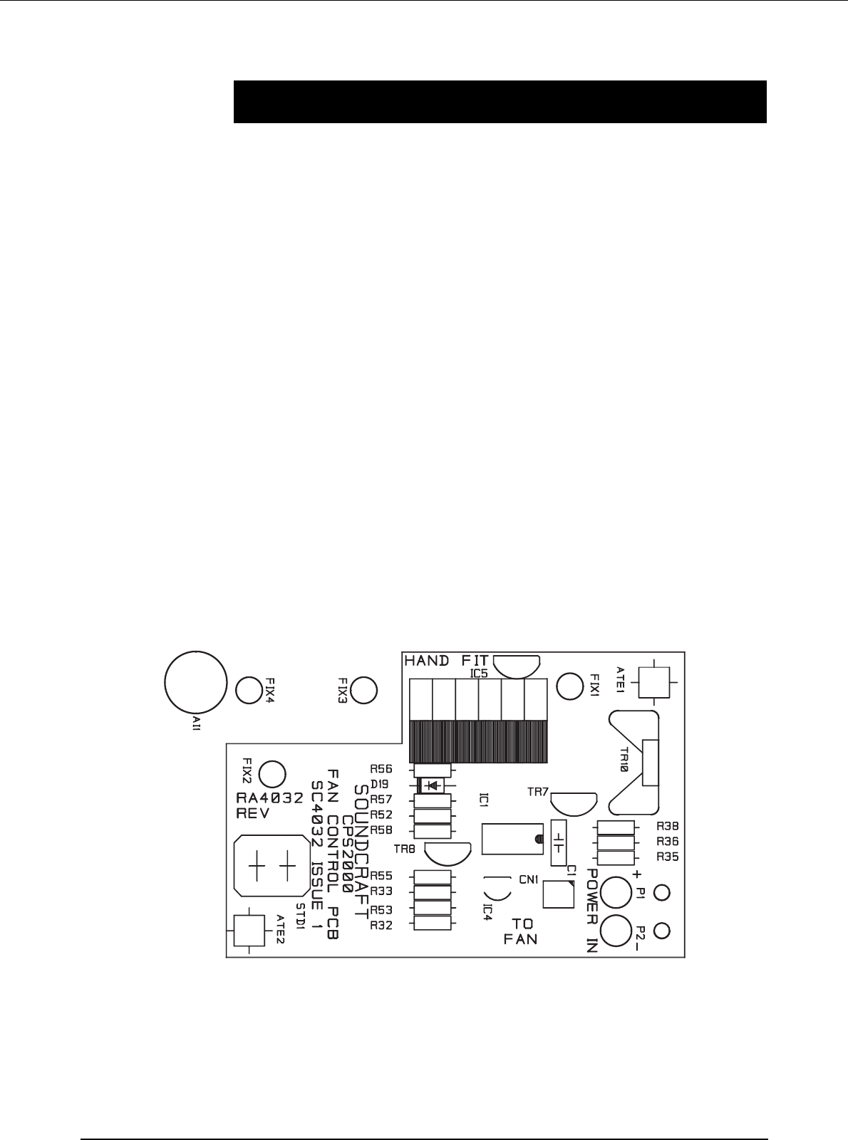
CPS2000 Fan Control & PCB SC4032
Technical Description
The later models of the CPS2000 are fitted with a fan control servo system that adapts the fan
speed to the power drawn. This gives a substantial reduction in fan noise under almost all
circumstances; the exception being 10% high mains and maximum current drawn, which
naturally sets the fan to full speed. The PCB (with associated mounting bracket) may be
retrofitted to existing CPS2000 units.
The servo circuit consists of opamp IC1-A, temperature sensor IC5, shunt regulator IC4, and
fan control devices TR7,TR10. IC4 maintains 2.50V between its "anode" and "cathode"; this is
the precise voltage that drives the reference chain R53,55. TR8 also uses this voltage to set its
emitter at 4.4V above ground; this keeps IC1’s inputs within their common-mode range. Thus
both ends of the voltage divider R53-R55 are fixed at defined voltages. LM35DZ temperature
sensor IC5 outputs 10mV per degreeC above freezing point (0 degC) and applies it to IC1-A
non-inverting input. The desired heatsink temperature is set at the junction of R53,55, which
sits at +5.0V approx. This is 600mV above the +4.4V rail, and so represents 60 degC. R52,57
set the servo loop gain. This is designed to be safely below the level at which slow thermal
oscillations would occur. R56,D19 increase the loop gain when IC1-A output is below 4V. This
prevents the fan sitting for long periods in a not-quite-running state where it consumes current
but does not rotate.
The voltage range 1-4V where this occurs is thus skipped over quickly. The fan is driven through
feedback amplifier TR7,10, which has a voltage gain of 1.3 times. This allows the fan to be
driven over its full operating voltage range despite the output saturation limits of IC1-A. This
gives improved cooling at high temperatures and mains voltages. The CPS2000 thermal
shutdown system is quite separate and has no connection with this PCB.
36 Fan Control
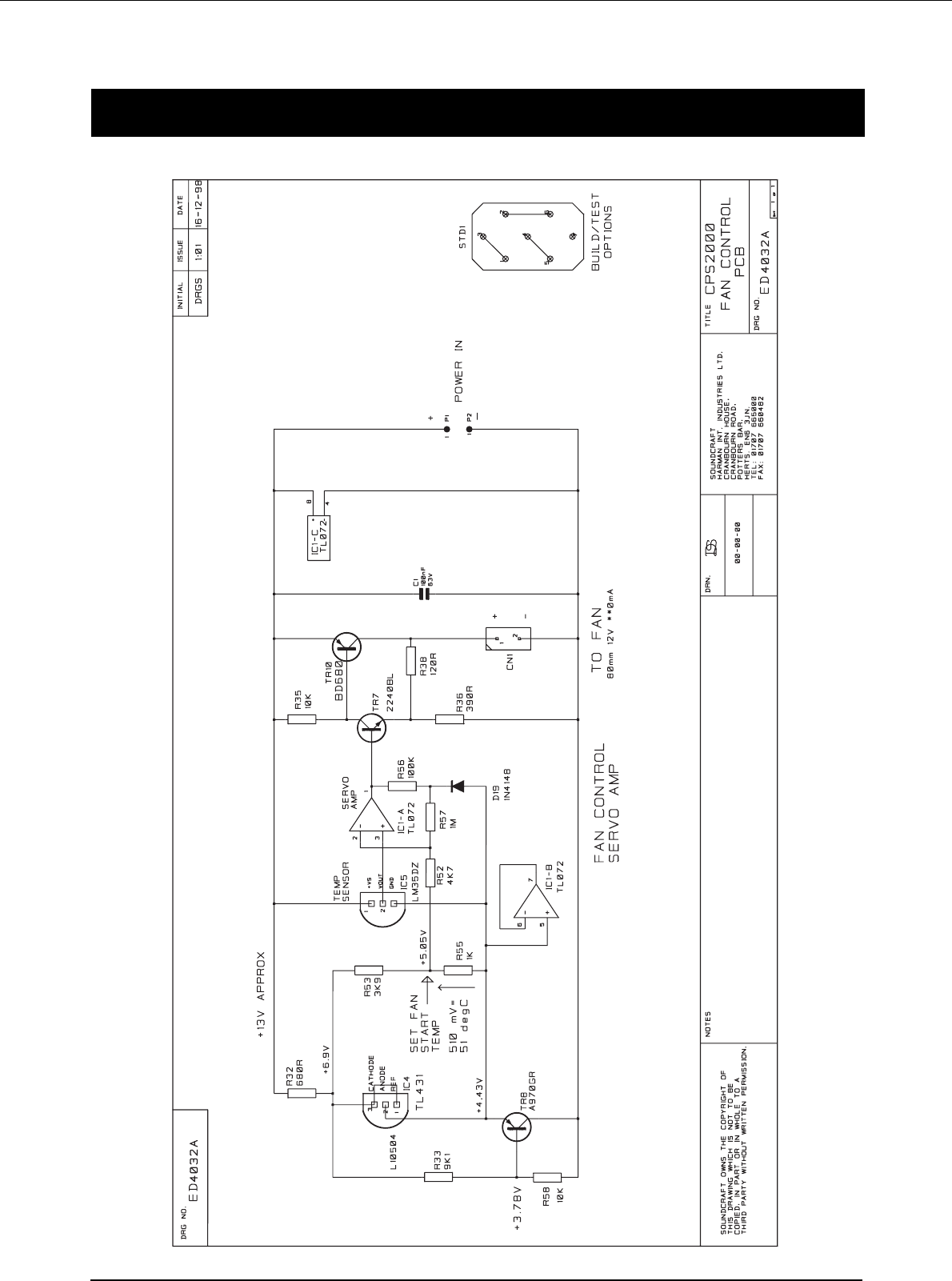
CPS2000 Fan Controller Circuit Diagram
Fan Control 37

38 Fan Control

Technical Drawings 39
Technical Drawings
Circuit Diagrams
ED3804A Issue 9
ED3804B Issue 9
ED3804A Issue 10
ED3804B Issue 10
ED3817 Issue 4
PCB Layouts
SC3804 Issue 9
SC3804 Issue 10
SC3817 Issue 4
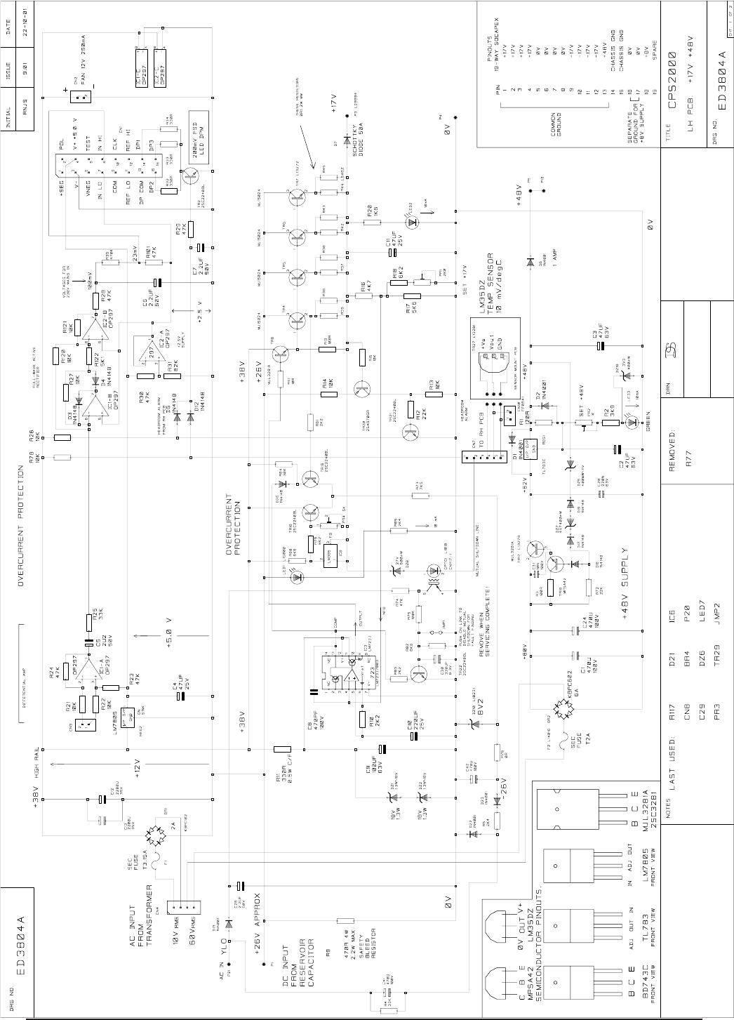
Technical Drawings40
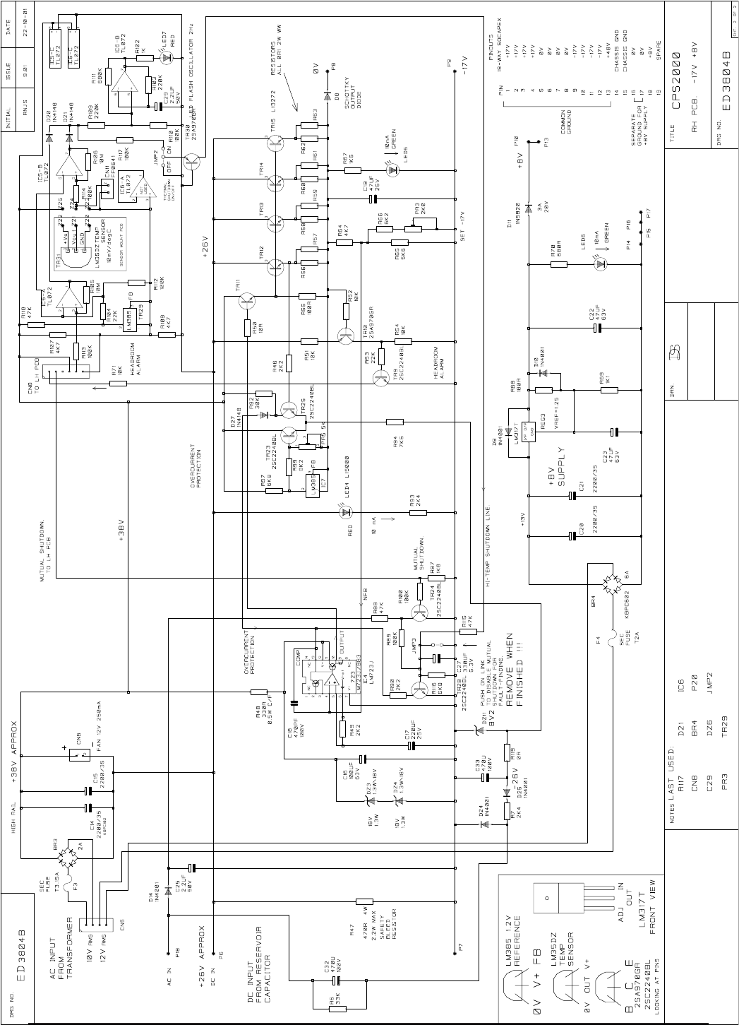
Technical Drawings 41
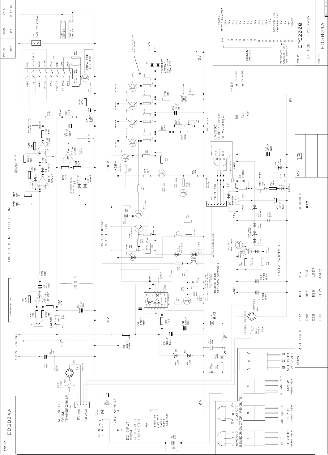
Technical Drawings42
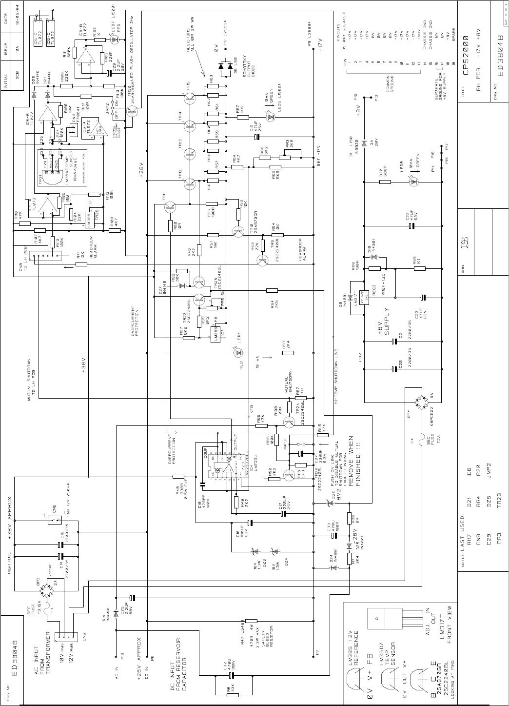
Technical Drawings 43
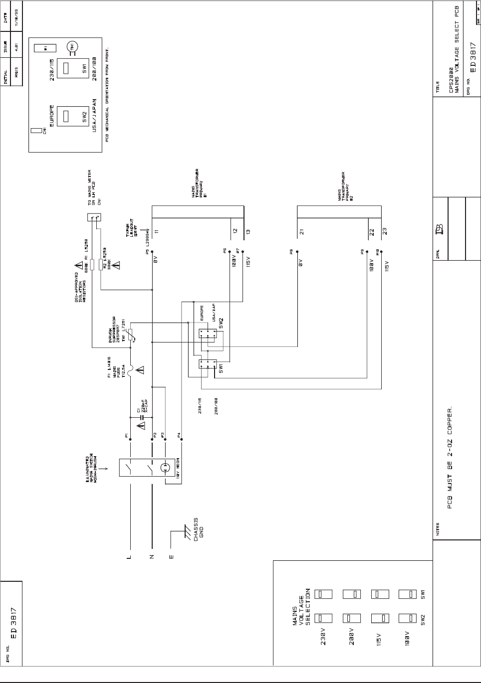
Technical Drawings44
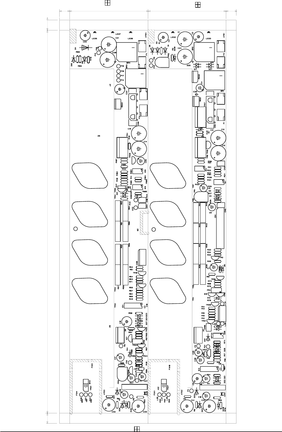
Technical Drawings 45
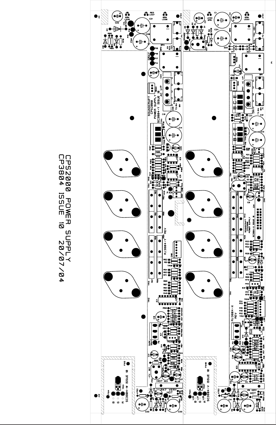
Technical Drawings46
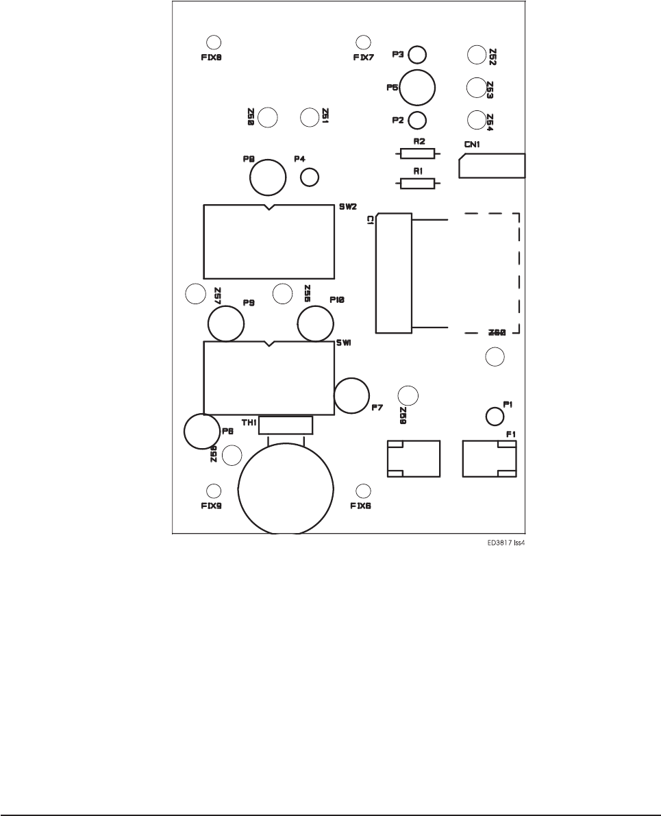
Technical Drawings 47

Technical Drawings48
