Southco H3EM62 Electronic Swing handle User Manual General open questions
Southco,. Inc Electronic Swing handle General open questions
UserManual.wiki
>
Southco
>
H3EM62 User Manual
Users Manual
Navigation menu
Upload a User Manual
Namespaces
Wiki Guide
HTML
PDF
Info
Views
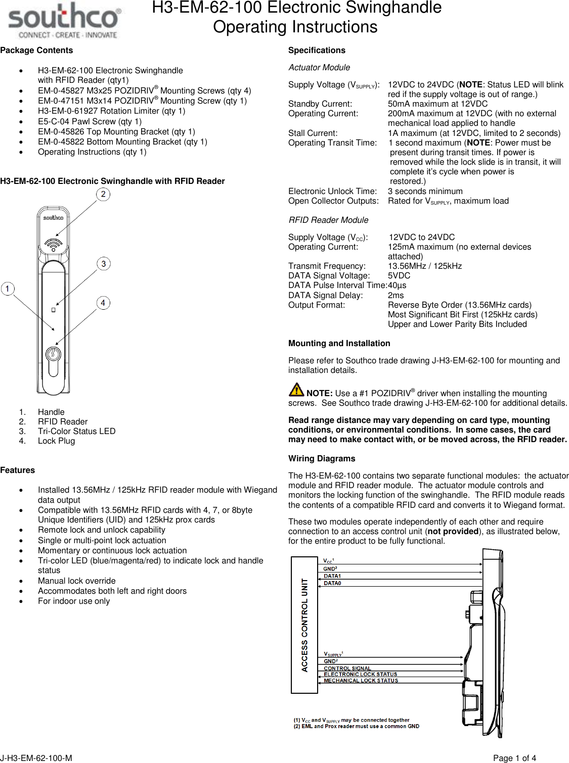
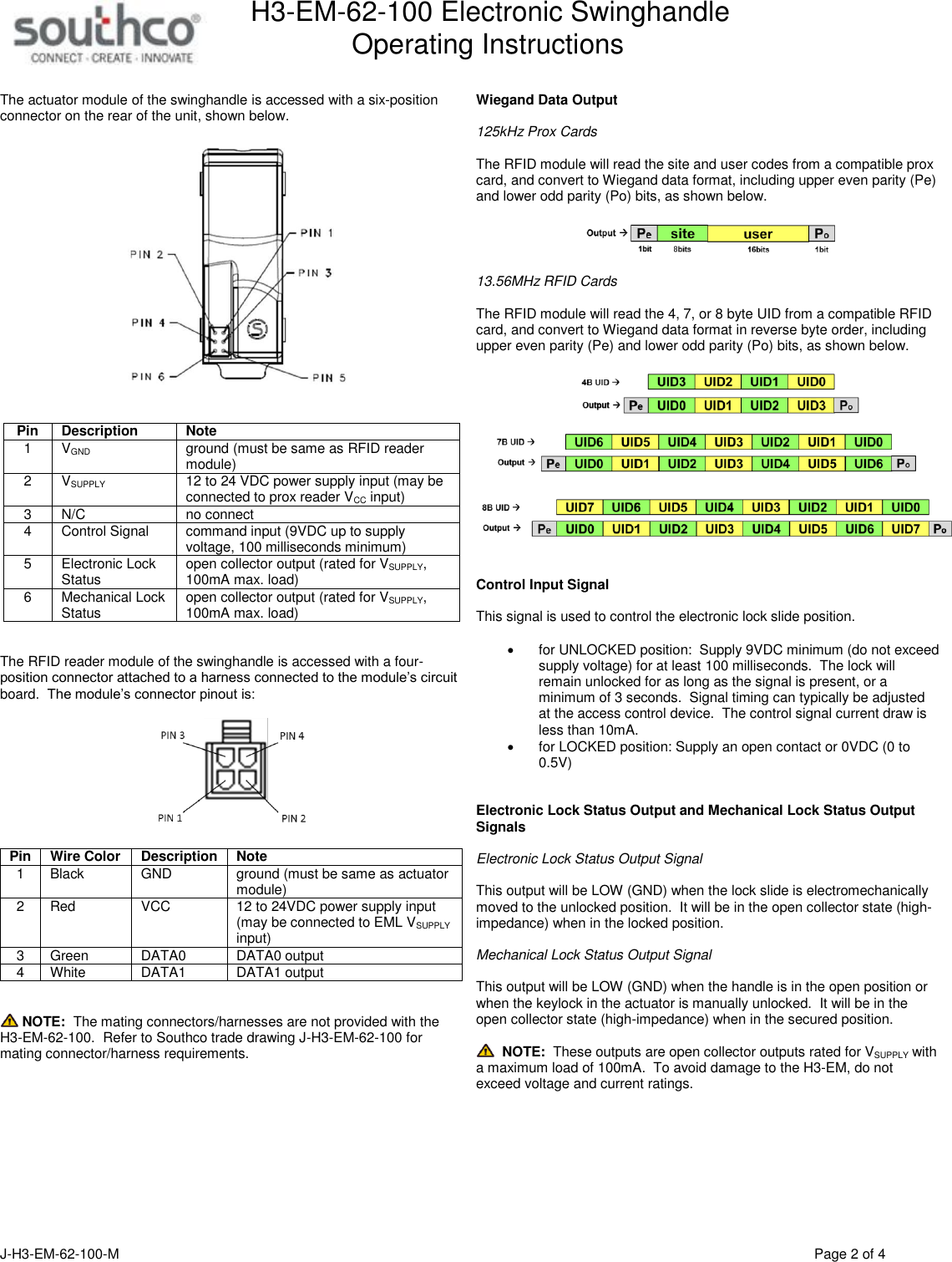
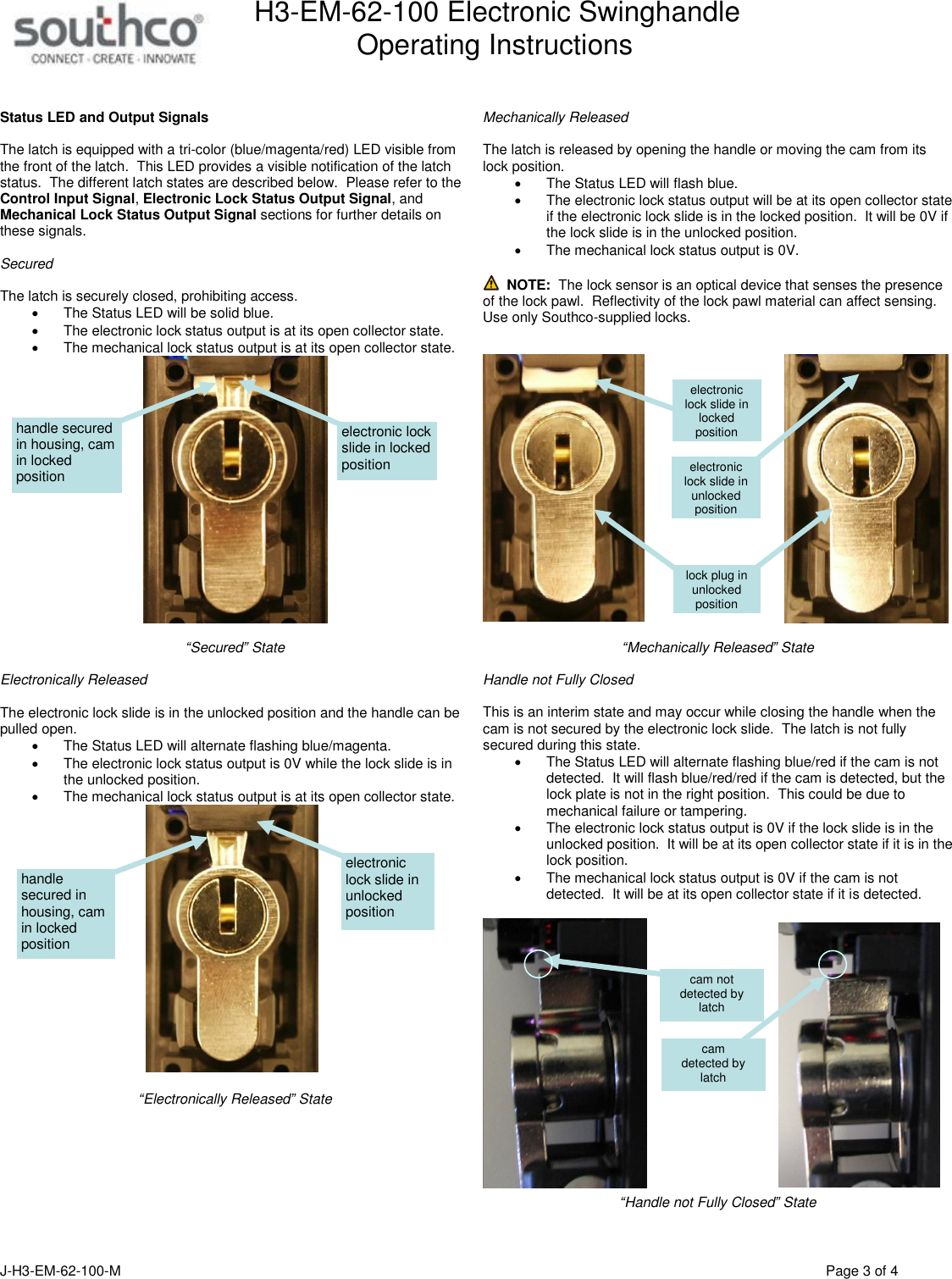
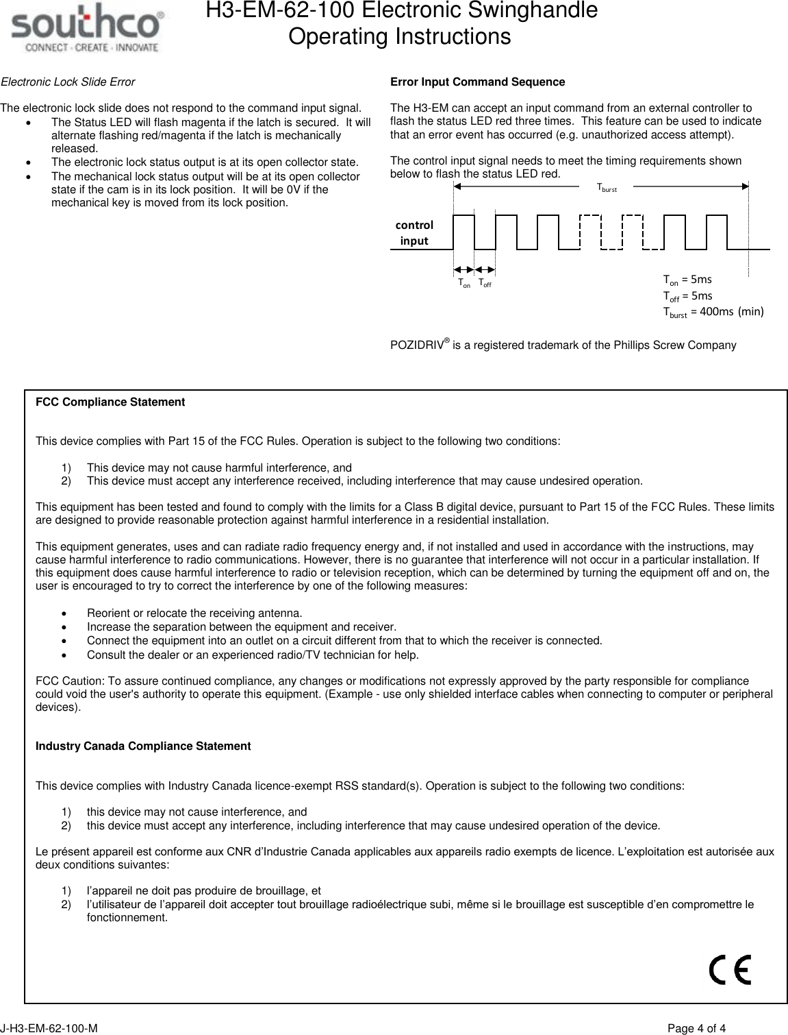
User Manual
Discussion / Help
Navigation