Southco H3EM99521 Swinghandle with RFID Reader User Manual General open questions
Southco,. Inc Swinghandle with RFID Reader General open questions
Southco >
User Manual
H3-EM-99-521 Electronic Swinghandle
Operating Instructions
J-H3-EM-99-521-M_revC Page 1 of 4
Package Contents
H3-EM-99-521 Electronic Swinghandle
with RFID Reader (qty1)
EM-0-45827 M3x25 POZIDRIV® Mounting Screws (qty 4)
EM-0-47151 M3x14 POZIDRIV® Mounting Screw (qty 1)
H3-EM-0-61927 Rotation Limiter (qty 1)
E5-C-04 Pawl Screw (qty 1)
EM-0-45826 Top Mounting Bracket (qty 1)
EM-0-45822 Bottom Mounting Bracket (qty 1)
Operating Instructions (qty 1)
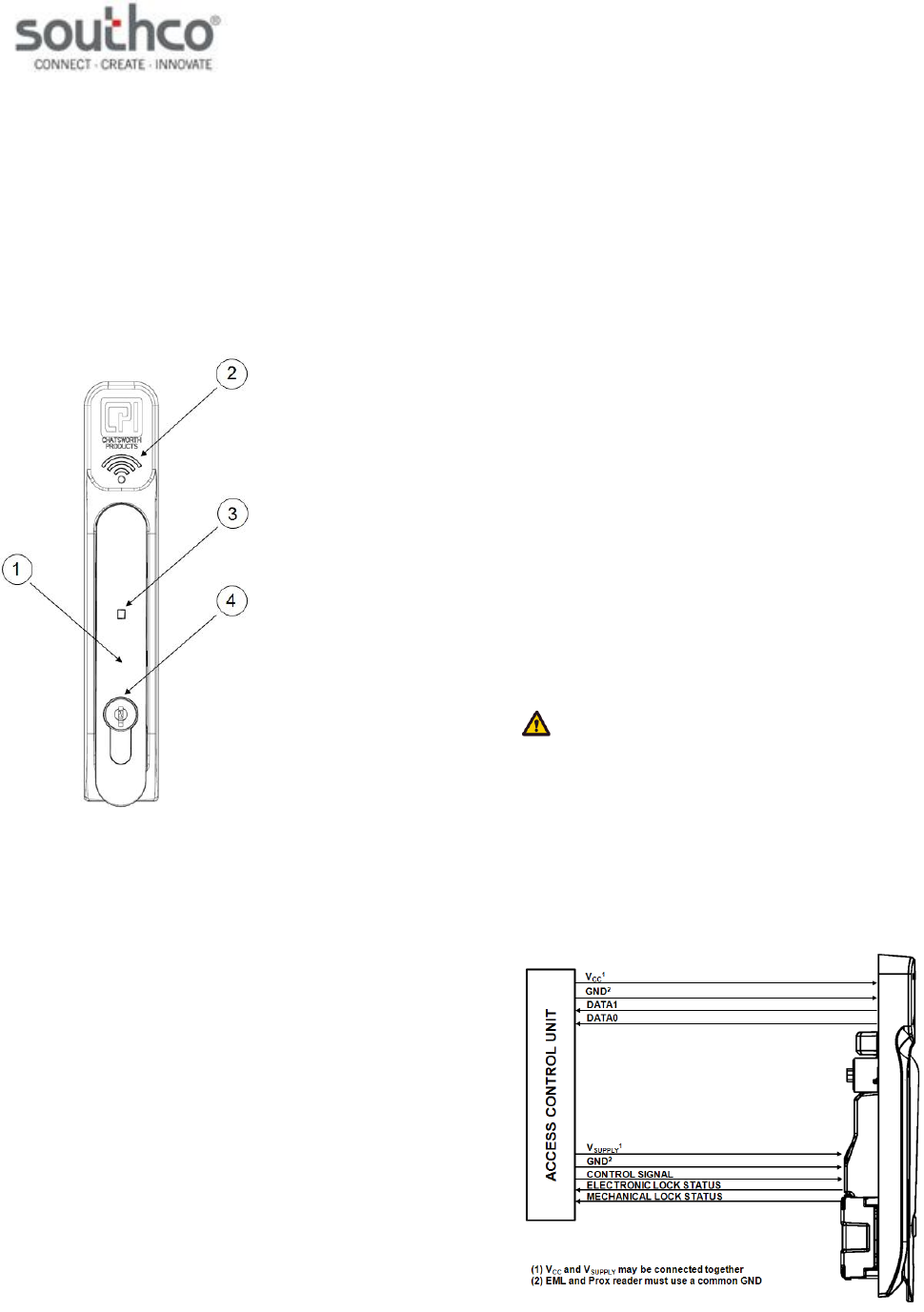
H3-EM-99-521 Electronic Swinghandle with RFID Reader
1. Handle
2. RFID Reader
3. Tri-Color Status LED
4. Lock Plug
Features
Installed 13.56MHz / 125kHz RFID reader module with Wiegand
data output
Compatible with 13.56MHz RFID cards with 4, 7, or 8byte
Unique Identifiers (UID) and 125kHz prox cards
Remote lock and unlock capability
Single or multi-point lock actuation
Momentary or continuous lock actuation
Tri-color LED (blue/magenta/red) to indicate lock and handle
status
Manual lock override
Accommodates both left and right doors
For indoor use only
Specifications
Actuator Module
Supply Voltage (VSUPPLY): 5VDC
Standby Current: 25mA maximum at 5VDC
Operating Current: 150mA maximum at 5VDC (with no external
mechanical load applied to handle
Stall Current: 650mA maximum (at 5VDC, limited to 2 sec)
Operating Transit Time: 1 second maximum (NOTE: Power must be
present during transit times. If power is
removed while the lock slide is in transit, it will
complete it’s cycle when power is
restored.)
Electronic Unlock Time: 3 seconds minimum
Open Collector Outputs: Rated for VSUPPLY, 100mA maximum load
RFID Reader Module
Supply Voltage (VCC): 5VDC (± 10%)
Operating Current: 125mA maximum (no external devices
attached)
Transmit Frequency: 13.56MHz / 125kHz
DATA Signal Voltage: 5VDC
DATA Pulse Interval Time: 40µs
DATA Signal Delay: 2ms
Output Format: Reverse Byte Order (13.56MHz cards)
Most Significant Bit First (125kHz cards)
Upper and Lower Parity Bits Included
Mounting and Installation
Please refer to Southco trade drawing J-H3-EM-99-521 for mounting and
installation details.
NOTE: Use a #1 POZIDRIV® driver when installing the mounting
screws. See Southco trade drawing J-H3-EM-99-521 for additional details.
Wiring Diagrams
The H3-EM-99-521 contains two separate functional modules: the actuator
module and RFID reader module. The actuator module controls and
monitors the locking function of the swinghandle. The RFID module reads
the contents of a compatible RFID card and converts it to Wiegand format.
These two modules operate independently of each other and require
connection to an access control unit (not provided), as illustrated below,
for the entire product to be fully functional.
H3-EM-99-521 Electronic Swinghandle
Operating Instructions
J-H3-EM-99-521-M_revC Page 2 of 4
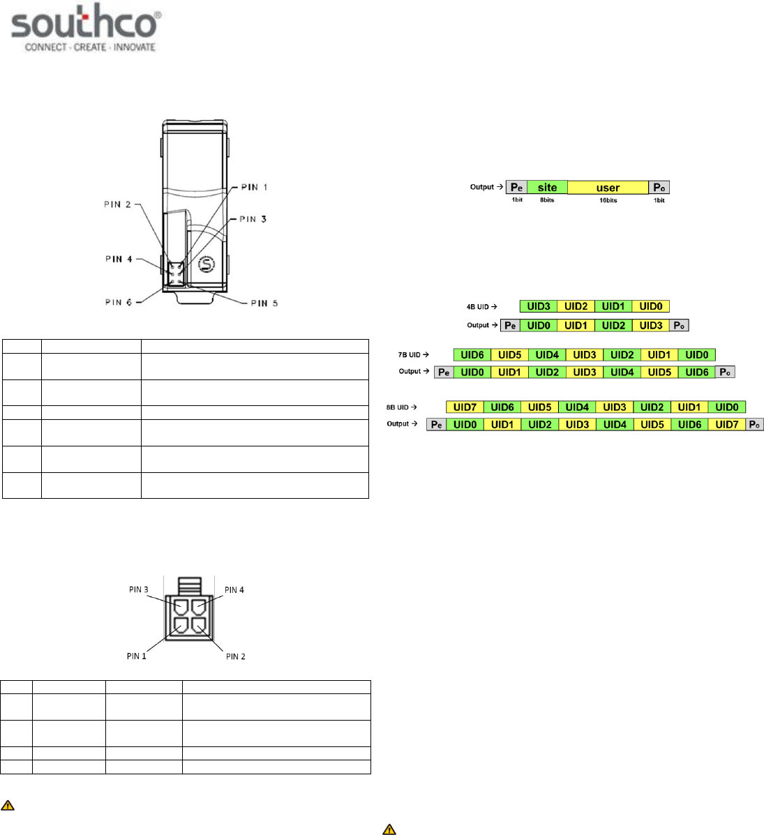
The actuator module of the swinghandle is accessed with a six-position
connector on the rear of the unit, shown below.
Pin
Description
Note
1
VGND
ground (must be same as RFID reader
module)
2
VSUPPLY
5VDC power supply input (may be
connected to RFID reader VCC input)
3
N/C
no connect
4
Control Signal
command input (5VDC, 100 milliseconds
minimum)
5
Electronic Lock
Status
open collector output (rated for VSUPPLY,
100mA max. load)
6
Mechanical Lock
Status
open collector output (rated for VSUPPLY,
100mA max. load)
The RFID reader module of the swinghandle is accessed with a four-
position connector attached to a harness connected to the module’s circuit
board. The module’s connector pinout is:
Pin
Wire Color
Description
Note
1
Black
GND
ground (must be same as actuator
module)
2
Red
VCC
5VDC power supply input (may be
connected to EML VSUPPLY input)
3
Green
DATA0
DATA0 output
4
White
DATA1
DATA1 output
NOTE: The mating connectors/harnesses are not provided with the
H3-EM-99-521. Refer to Southco trade drawing J-H3-EM-99-521 for
mating connector/harness requirements.
Wiegand Data Output
125kHz Prox Cards
The RFID module will read the site and user codes from a compatible prox
card, and convert to Wiegand data format, including upper even parity (Pe)
and lower odd parity (Po) bits, as shown below.
13.56MHz RFID Cards
The RFID module will read the 4, 7, or 8 byte UID from a compatible RFID
card, and convert to Wiegand data format in reverse byte order, including
upper even parity (Pe) and lower odd parity (Po) bits, as shown below.
Control Input Signal
This signal is used to control the electronic lock slide position.
for UNLOCKED position: Supply 5VDC for at least 100
milliseconds. The lock will remain unlocked for as long as the
signal is present, or a minimum of 3 seconds. Signal timing can
typically be adjusted at the access control device. The control
signal current draw is less than 10mA.
for LOCKED position: Supply an open contact or 0VDC (0 to
0.5V)
Electronic Lock Status Output and Mechanical Lock Status Output
Signals
Electronic Lock Status Output Signal
This output will be LOW (GND) when the lock slide is electromechanically
moved to the unlocked position. It will be in the open collector state (high-
impedance) when in the locked position.
Mechanical Lock Status Output Signal
This output will be LOW (GND) when the handle is in the open position or
when the keylock in the actuator is manually unlocked. It will be in the
open collector state (high-impedance) when in the secured position.
NOTE: These outputs are open collector outputs rated for VSUPPLY with
a maximum load of 100mA. To avoid damage to the H3-EM, do not
exceed voltage and current ratings.
H3-EM-99-521 Electronic Swinghandle
Operating Instructions
J-H3-EM-99-521-M_revC Page 3 of 4
Status LED and Output Signals
The latch is equipped with a tri-color (blue/magenta/red) LED visible from
the front of the latch. This LED provides a visible notification of the latch
status. The different latch states are described below. Please refer to the
Control Input Signal, Electronic Lock Status Output Signal, and
Mechanical Lock Status Output Signal sections for further details on
these signals.
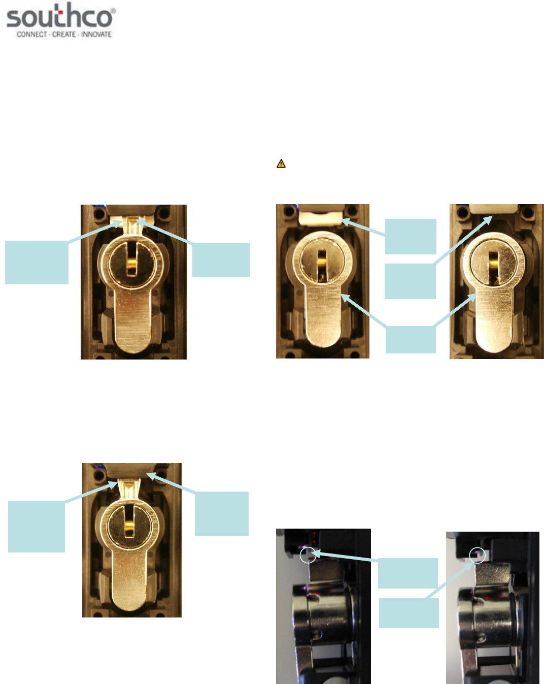
Secured
The latch is securely closed, prohibiting access.
The Status LED will be solid blue.
The electronic lock status output is at its open collector state.
The mechanical lock status output is at its open collector state.
“Secured” State
Electronically Released
The electronic lock slide is in the unlocked position and the handle can be
pulled open.
The Status LED will alternate flashing blue/magenta.
The electronic lock status output is 0V while the lock slide is in
the unlocked position.
The mechanical lock status output is at its open collector state.
“Electronically Released” State
Mechanically Released
The latch is released by opening the handle or moving the cam from its
lock position.
The Status LED will flash blue.
The electronic lock status output will be at its open collector state
if the electronic lock slide is in the locked position. It will be 0V if
the lock slide is in the unlocked position.
The mechanical lock status output is 0V.
NOTE: The lock sensor is an optical device that senses the presence
of the lock pawl. Reflectivity of the lock pawl material can affect sensing.
Use only Southco-supplied locks.
“Mechanically Released” State
Handle not Fully Closed
This is an interim state and may occur while closing the handle when the
cam is not secured by the electronic lock slide. The latch is not fully
secured during this state.
The Status LED will alternate flashing blue/red if the cam is not
detected. It will flash blue/red/red if the cam is detected, but the
lock plate is not in the right position. This could be due to
mechanical failure or tampering.
The electronic lock status output is 0V if the lock slide is in the
unlocked position. It will be at its open collector state if it is in the
lock position.
The mechanical lock status output is 0V if the cam is not
detected. It will be at its open collector state if it is detected.
“Handle not Fully Closed” State
electronic lock
slide in locked
position
handle secured
in housing, cam
in locked
position
electronic
lock slide in
unlocked
position
handle
secured in
housing, cam
in locked
position
electronic
lock slide in
unlocked
position
electronic
lock slide in
locked
position
lock plug in
unlocked
position
cam
detected by
latch
cam not
detected by
latch
H3-EM-99-521 Electronic Swinghandle
Operating Instructions
J-H3-EM-99-521-M_revC Page 4 of 4
Electronic Lock Slide Error
The electronic lock slide does not respond to the command input signal.
The Status LED will flash magenta if the latch is secured. It will
alternate flashing red/magenta if the latch is mechanically
released.
The electronic lock status output is at its open collector state.
The mechanical lock status output will be at its open collector
state if the cam is in its lock position. It will be 0V if the
mechanical key is moved from its lock position.
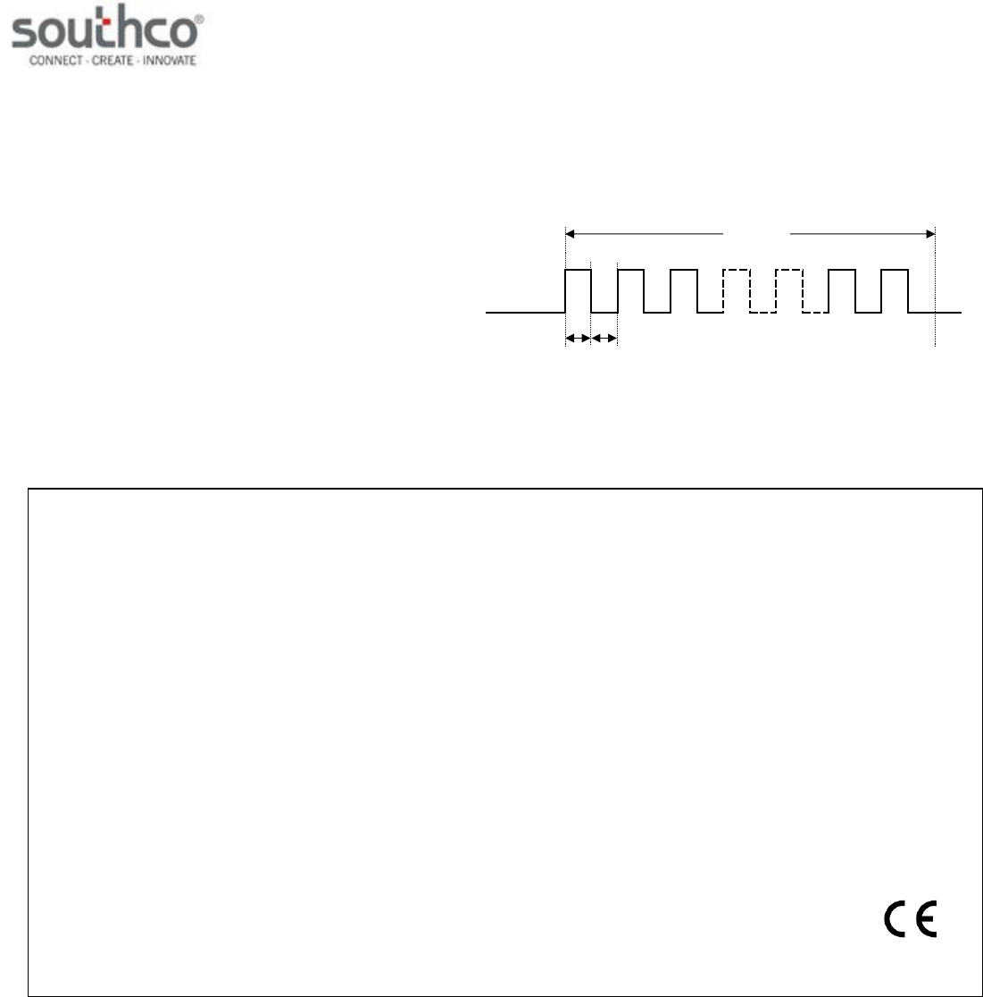
Error Input Command Sequence
The H3-EM can accept an input command from an external controller to
flash the status LED red three times. This feature can be used to indicate
that an error event has occurred (e.g. unauthorized access attempt).
The control input signal needs to meet the timing requirements shown
below to flash the status LED red.
POZIDRIV® is a registered trademark of the Phillips Screw Company
Ton = 5ms
Ton
Toff = 5ms
Toff
Tburst
Tburst = 400ms (min)
control
input
FCC Compliance Statement
This device complies with Part 15 of the FCC Rules. Operation is subject to the following two conditions:
1) This device may not cause harmful interference, and
2) This device must accept any interference received, including interference that may cause undesired operation.
This equipment has been tested and found to comply with the limits for a Class B digital device, pursuant to Part 15 of the FCC Rules. These limits
are designed to provide reasonable protection against harmful interference in a residential installation.
This equipment generates, uses and can radiate radio frequency energy and, if not installed and used in accordance with the instructions, may
cause harmful interference to radio communications. However, there is no guarantee that interference will not occur in a particular installation. If
this equipment does cause harmful interference to radio or television reception, which can be determined by turning the equipment off and on, the
user is encouraged to try to correct the interference by one of the following measures:
Reorient or relocate the receiving antenna.
Increase the separation between the equipment and receiver.
Connect the equipment into an outlet on a circuit different from that to which the receiver is connected.
Consult the dealer or an experienced radio/TV technician for help.
FCC Caution: To assure continued compliance, any changes or modifications not expressly approved by the party responsible for compliance
could void the user's authority to operate this equipment.