Southwest Microwave 380 Outdoor Microwave Transceiver User Manual 380 Tech Manual
Southwest Microwave Inc Outdoor Microwave Transceiver 380 Tech Manual
380 Tech Manual
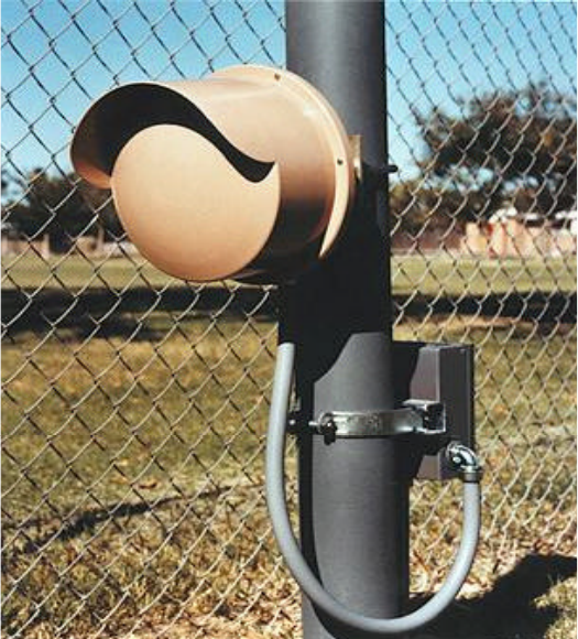
Southwest Microwave, Inc.
Security Systems Division
TECHNICAL MANUAL
MODEL 380
OUTDOOR MICROWAVE TRANSCEIVER
SOUTHWEST MICROWAVE, INC.
9055 S. McKemy Street
Tempe, Arizona 85284-2946
TEL (480) 783-0201
FAX (480) 783-0401
2
TABLE OF CONTENTS
INTRODUCTION.................................................................................................................................................................3
OPERATION.........................................................................................................................................................................3
THEORY ...............................................................................................................................................................................4
SPECIFICATIONS................................................................................................................................................................7
SITE PREPARATION ..........................................................................................................................................................8
LOCATION OF TRANSCEIVERS......................................................................................................................................9
MULTIPLE UNIT INSTALLATIONS ..............................................................................................................................11
MOUNTING........................................................................................................................................................................13
POWER WIRING ...............................................................................................................................................................14
CONNECTIONS .................................................................................................................................................................15
ALIGNMENT AND TEST .................................................................................................................................................16
PREVENTATIVE MAINTENANCE ................................................................................................................................17
OPTIONAL EQUIPMENT.................................................................................................................................................18
WARRANTY AND RETURN INFORMATION..............................................................................................................18
NOTE: This manual is for Models 380 and 380-33453 March 2003
3
INTRODUCTION_____________________________________________________________
Model 380 Outdoor Microwave Transceiver incorporates state-of-the-art technology and innovative electronic circuitry
to provide reliable detection in the outdoor environment. A unique continuously variable Range Cutoff (RCO) circuit
allows maximum detection range to be established independently of object size, thereby eliminating alarms caused by
large objects beyond the desired detection range. Model 380 is also equipped with Zero Range Suppression (ZRS)
circuitry that reduces sensitivity to small objects very close to the transceiver so that alarms due to rain or vibration are
minimized.
Model 380 includes synchronization and addressing circuitry that enables simultaneous operation of up to 16 units
without mutual interference. The Model 380 is also built with staggered RF frequencies (Channel A and B) to help
minimize mutual interference. Model 380 may be mounted to a variety of posts or wall structures by means of its
universal-mounting bracket. A military style multi-pin connector, at the rear of the transceiver housing, permits remote
monitoring and diagnostics of critical system parameters.
OPERATION_________________________________________________________________
Model 380 includes both transmitter and receiver in a single enclosure. The transmitter radiates microwave energy that
is reflected back into the receiver by objects within the detection zone. The observed detection zone is established by
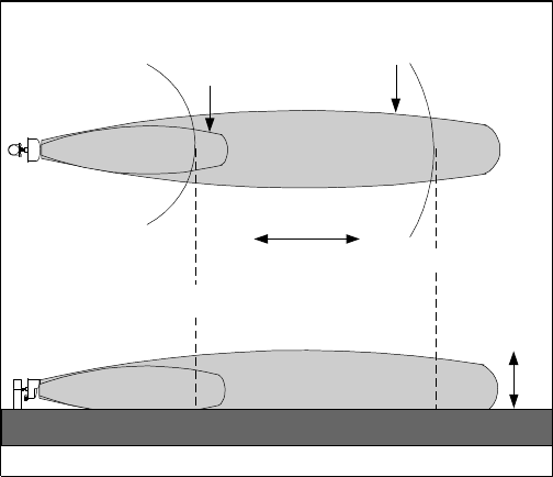
two controls - Sensitivity and Range. Figure 1A shows the zone of detection (horizontal pattern) for an upright man
when Model 380 is mounted 2.5 feet (.75 meters) above smooth earth with its beam oriented parallel to the ground. The
Range control adjusts the maximum range of the system and the Sensitivity control primarily adjusts the width. Figure
1B shows the vertical pattern for the same configuration, note that the detection zone does not extend into the small area
immediately under Model 380.
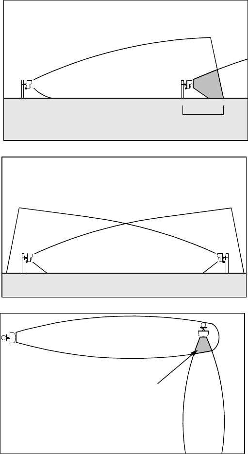
This area varies with the Sensitivity setting as shown in Figure 2. In order to provide uninterrupted detection of a man
walking or crawling on his hands and knees, an additional unit must provide overlap protection such as shown in Figure
3. Detection of a man crawling "commando-style" may require additional overlap or special site preparation.
Sensitivity should always be adjusted to the absolute lowest setting that will meet site security requirements. Excessively
high sensitivity may cause nuisance alarms from high grass, small birds or windblown debris in the detection zone.
Model 380 responds to any motion within the detection zone.
Figure 1 - Model 380 Detection Pattern
SENSITIVITY MINIMUM
SENSITIVITY MAXIMUM
ACTIVE
DETECTION
PATTERN
CUTOFF
RCO
CONTINUOUSLY
VARIABLE
50' MIN 200' MAX
(3.4m)
(15m) (122m)
A) HORIZONTAL PATTERN
B) VERTICAL PATTERN
15' MAX
PATTERN
HEIGHT

4
THEORY_____________________________________________________________________
A microwave transceiver transmits microwave energy into the detection zone, and objects in the zone reflect energy
back to its receiver. Whenever an object is moving, the Doppler effect shifts the frequency of its reflection and the
transceiver generates an alarm whenever it detects a frequency shift in the reflected energy. The size of a frequency-
shifted reflection that will cause alarms is varied by the Sensitivity control causing the detection zone for any particular
object to vary as shown in Figure 1. Note that Figure 1 applies to an upright walking man. The detection zone for a
large object such as a truck would be larger and for a small object such as a man, crawling would be smaller.
In Model 380, the transmitter is periodically turned on and off, but the receiver is turned on only for a short period after
the transmitter is turned on. Because microwave energy always travels at nearly the speed of light, elapsed time between
transmission and reception provides an accurate measurement of range (distance) from Model 380 to whatever object is
being illuminated. By turning the receiver on only during the period corresponding to maximum desired range,
reflections from objects beyond this range are ignored, even if the reflections are very large. In Model 380, the range
control determines the time that the receiver observes the reflections and thus sets the maximum (RCO) distance as
shown in Figure 1.
Reflections from small objects such as raindrops very near the transceiver are frequently as large as reflections from a
man in the detection zone. Model 380 overcomes this problem by transmitting two different microwave frequencies on
alternate transmitter pulses. Because each object reflects two different frequencies, the receiver can determine the
distance to each object. At zero range (in the vicinity of the radome), the phase difference between the two frequencies
is approximately zero. By combining the two Doppler signals in a difference amplifier, the gain is reduced significantly.
In order to insure a continuous perimeter, it is necessary to provide sufficient overlap so that the dead zone immediately
below and behind the sensor is protected. Figures 2 and 3 show required overlap information.
Figure 2 - Required Overlap vs. Sensitivity
MIN 1/2 MAX
DEAD ZONE
SENSITIVITY
REQUIRED OVERLAP
(2.5 foot (0.8m) mounting height)
40' (12.2m)
30' (9.1m)
20' (6.1m)
10' (3.0m)
5' (1.5m)
0'
50' (15.2m)
MAXIMUM SECURITY
MINIMUM SECURITY
5
Figure 3 - Overlap of Model 380 Detection Zone
Figure 4 shows a block diagram of Model 380. Logic pulses generated by the synchronization phase-locked loop (PLL)
and the associated counter and 4-bit comparator provide the command for turning the transmitter on and off at a
prescribed rate, and at one of 16 unique periods of time or addresses. A signal is also derived for switching the
transmitter alternately between the two frequencies required for Zero Range Suppression.
The Range control sets the delay generated logic functions initiated by the turn on of the transmitter.
The transmitter is a cavity stabilized fundamental GUNN oscillator that provides 32 milliwatts (peak) of microwave
power. Most of the oscillator power is transmitted into space by the parabolic antenna, but a small portion is mixed with
the reflected signal and is coupled to a microwave detector within the antenna assembly. The detector is a Schottky
diode that extracts the Doppler shift frequency from the reflected microwave energy.
OVERLAP AREA
Overlap Area

6
The Doppler signal is amplified and then gated to one of two sample and hold amplifiers. The amplifiers are selected by
means of S1 and S2 and are switched coincident with the alternate transmitter frequencies. SI and S2 are held closed for
a period of time determined by the range cut-off circuit. Range gating is accomplished by turning on the switch at the
same time the transmitter is activated. The switch is then opened at a time selected by the range cut-off circuit so that the
information entering the receiver due to targets outside the range cut-off are not processed. The sampling capacitors
following the switches hold their charge when the switches are opened. This provides a means for reconstructing each
signal after it is sampled.
At the differential amplifier input, the phase between channels is a function of distance to the target and separation of the
two transmitter frequencies. Signals arriving from RCO distance are out of phase while signals from zero distance are in
phase. Thus, amplifier output is large for signals from RCO distance and small for signals from zero distance.
The differential amplifier output is amplified by a factor established by the Sensitivity control and compared with
positive and negative voltage thresholds. Whenever the signal exceeds plus or minus one volt, a pulse is delivered to an
integrator. After a predetermined number of pulses have been stored, the integrator output voltage exceeds alarm
threshold and the alarm relay is de-energized for two seconds.
A test function is included in Model 380. When gated on by a +5 to +12 VDC command (at the terminal block), the test
function provides a phantom signal into the transmitter and receiver circuits to generate an alarm and test the entire 380
detection system.
Figure 4 - Block Diagram Model 380
4 BIT
COMP
ADDR
PLL
CTR
MASTER
OUTPUT
SLAVE
INPUT
1.0 uSec
AMP
AMP
+
-
SENS
VL
ALARM
CKTS
THRESHOLD
LOW-PASS
FILTER
RCO
TIMING
RANGE
FbFa
TX
OSC
VCO
DRIVER
Fc
Fc Fd
+
-
LOCK
S1
RELAY
TB1-6
TB1-7
TB1-8
TB1-4
TB1-5
N.O.
COM
N.C.
COM
N.C.
ALARM
ALARM
TB1-10
TB1-11
TB1-12
TB1-13
TB1-14
+
+
-
-
SUPPLY
VCO
SUPPLY
POWER
TB1-9
TB1-1
TB1-2
P1-A
POWER
P1-D
+
-
P1-B
+9V
+5V
+7V TEST
P1-F
P1-C
P1-E
LED
LED
LED
TAMPER
SWITCH
TB1-3 N.O.
ONE
SHOT
S2
VH
+5V
SYNC
ON OFF
+2
LEADING
EDGE
DETECTOR
VH
VL
7
Model 380 is also equipped with an interference/tamper detection circuit. Should a metal container be placed over the
transceiver in an attempt to reduce the detection zone, the DC amplifier will detect a change in mixer peak output, and
after about 15 seconds an alarm will be generated.
The block diagram (see Figure 4) shows location for the various terminals and test points. Terminal block points are
designated TB while P indicates pin numbers for the military-style MS connector located at the rear of the transceiver.
MS connector test points may be conveniently monitored in the field by means of Model RM82 Performance Test Set.
SPECIFICATIONS____________________________________________________________
Equipment Supplied: Model 380 Outdoor Microwave Transceiver and universal swivel ball mounting bracket.
Detection Range: Variable from 50 ft (15m) to 200 ft (61m). This varies somewhat with site reflectivity.
Detection Width: Varies with range, 3 ft (0.91m) to 24 ft (7.3m). This varies somewhat with site reflectivity.
Target Size: 0.8 square meter (man/woman) walking, running or crawling on hands and knees. 0.2 square
meter (prone crawling man/woman) or 30cm metal sphere may be detected at a maximum
range of 150 feet (45.8m) with special site preparation.
Target Velocity: 0.2 ft/sec to 26 ft/sec (.06m/sec to 7.9m/sec).
Probability of Detection 0.99 minimums on 0.8 square meter target based on equipment S/N ratio.
Self-Supervision: 1) Antenna blockage causes constant alarm.
2) Remote test checks entire transceiver circuit.
Range Cut-Off: Targets will not be detected beyond a field-selected range (50 to 200 feet ± 10%).
Modulation: 3.12% duty cycle pulsed at 32 kHz ± 10%.
Internal Clock: 1 kHz ± 5%.
Sync Selection: Internal or external.
Output Power: Transmitter output power is 32 milliwatts peak at 24.125 GHz ± 50 MHz (USA).
Spurious Emissions: Conforms to F.C.C. Regulation Part 15 (USA).
DC Input: 11.0 to 14.0 VDC, 160mA nominal multiplex disabled, 220mA multiplex operational (master unit).
Alarm Relay Contacts: SPDT-Form C, 2 amps at 28 VDC.
Tamper Switch: SPDT, 2 amps, at 28 VDC.
LED Indicators: 1) Power "ON"
2) Alarm
3) Lock
Remote Monitor: External MS connector for connection of RM82 Performance Test Set.
Operating Environment: -30°F to +150°F (-35°C to +66°C). 0 - 100% relative humidity
8
Shipping Weight: 10 lbs (4.5 kg) total.
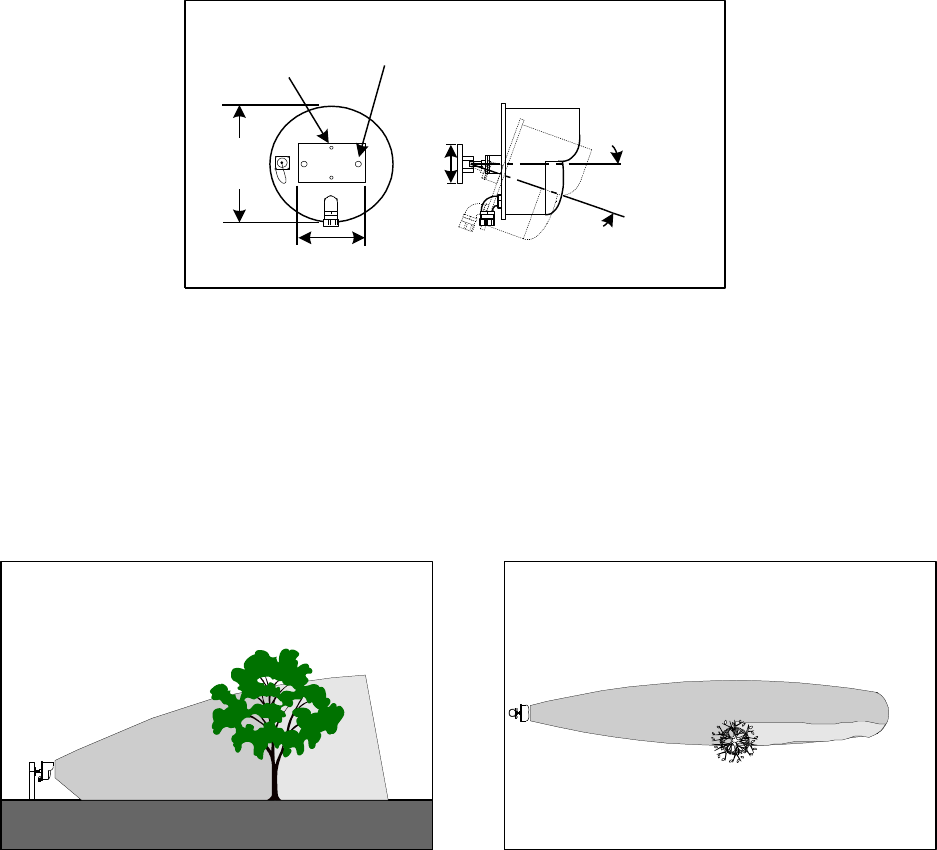
Dimensions:
Figure 5
SITE PREPARATION__________________________________________________________
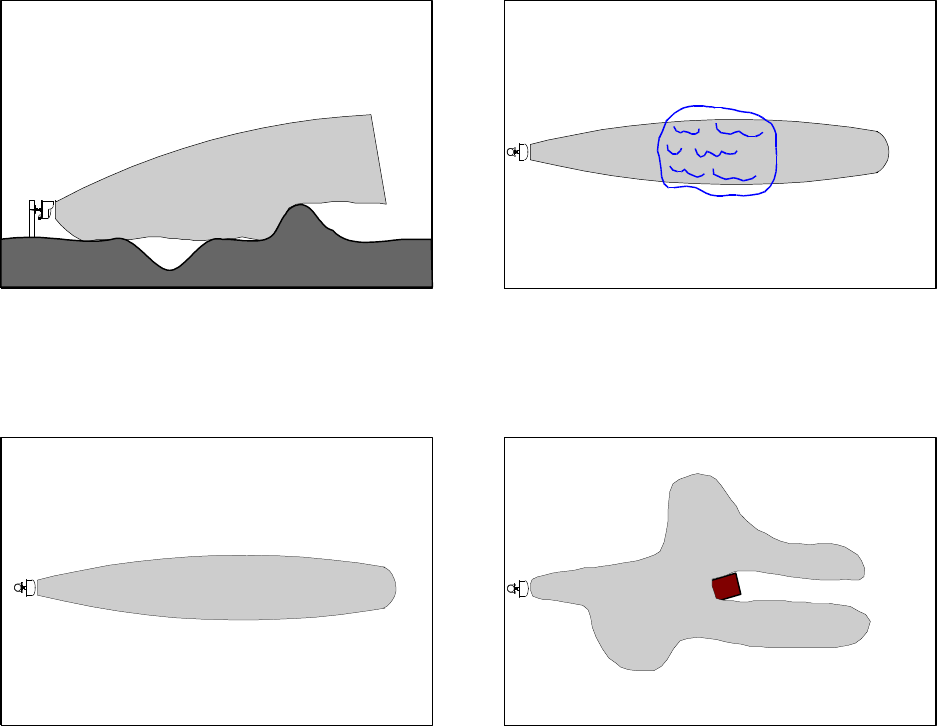
Clear the detection zone of trees, bushes, tall grass and all other objects that may obstruct, move, shake or vibrate. See
Figure 6. Detection zone for very large objects such as trees or trucks may be larger than the detection zone for man.
Figure 6
Level hills and ditches so that detection zone is flat to within six inches (15cm). For detection of prone crawling target,
detection zone should be flat to within three inches (8cm). Sharp hills or ditches may shadow an intruder. Provide good
drainage. Large puddles may cause nuisance alarms. Surface of the zone may be any stable, reasonably smooth material
such as concrete, asphalt, earth or gravel. Grass or vegetation must be kept cut to maximum of three inches (8cm) high.
See Figure 7.
3.5 in.
(8.9cm)
20
o
MAX TILT
ANY DIRECTION
Mounting Holes
4.5 in (11.4cm)
2.3 in (5.9cm)
6.0 in.
(15.2cm)
10.6 in.
(27cm)
Dia.
9
Figure 7
Be aware that large fixed objects reflect microwave energy and distort the detection zone. See Figure 8.
Figure 8
When installing Model 380 inside buildings, do not illuminate fluorescent lights. Flickering lights may cause nuisance
alarms. Be aware that detection zone pattern may penetrate windows, thin wooden doors or partition walls.
LOCATION OF TRANSCEIVERS_______________________________________________
Model 380 is normally mounted about 30 inches (76cm) above ground on a post and pointed parallel to the ground to
provide detection zone of Figure 1.
Always locate Model 380 inside a controlled access area to prevent nuisance alarms from random foot traffic, vehicles
or animals. Select locations, which provide protection from accidental damage as well as from tampering. Often simple
bumper guards will prevent damage from vehicles. See Figure 9.
Normal Detection Pattern Distorted Detection Pattern

10
Figure 9
When Model 380 is used inside a fence always orient the beam so that the detection zone does not include the fence
itself because the fence may move with high winds and cause nuisance alarms. Note that Model 380's range cutoff
(RCO) capability makes possible a variety of locations, but caution must be observed along the sides of the detection
zone to prevent alarms from large moving objects such as trucks which may pass inside the RCO distance. See Figure
10.
Figure 10
RCO DISTANCE
BUMPER GUARDS
DO DON'T
11
MULTIPLE UNIT INSTALLATIONS____________________________________________
Two or more Model 380's may be used together or with microwave T/R links such as Southwest Microwave
synchronized Model 300B/310B in order to provide a long interrupted detection zone. The unique multiplex feature of
the Model 380 allows the sensor to operate with up to 15 additional transceivers with no mutual interference, since only
one unit is activated at a time. The unit is also built with two (A and B) staggered RF frequencies to help reduce mutual
interference. Figure 11 shows the typical synchronization wiring configuration for the Model 380 transceivers. Any unit
may be selected to be the master clock but only one master is used for 15 slaves. Since all units are synchronized to a 1
kHz square wave that is supplied from the master, their turn-on time is controlled by an address code selectable at each
of the units. Table 1 gives the time slots versus address code. Unless there is no danger of interference, all units should
be set to different address codes.
When interfacing the Model 380 to microwave intrusion links, the unit that has the highest potential to cause mutual
interference is the Model 310B. This is because both units operate at the same K-band frequency. To synchronize the
Model 380 with synchronized units of Model 310B you would need to use the Model SMC10 Synchronizer Module to
act as the master clock. Contact Southwest Microwave for correct models and additional information.
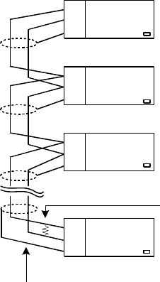
In order to properly terminate the twisted pair synchronization line it is necessary to add a 120 ohm, ¼ watt resistor
between the (+) and (-) synchronization terminals of the final unit in the chain.
When the units are synchronized, the lock LED on all "slave" units will not illuminate. Only the "master" unit will have
the lock LED illuminated.
Figure 11
MASTER
380
380
380
10 SET MASTER UNIT TO ADDRESS CODE 0
SET SECOND UNIT TO ADDRESS CODE 1
SET THIRD UNIT TO ADDRESS CODE 2
#22 or 24 GA. TWISTED SHIELDED PAIR
TERMINATE LAST UNIT OF CHAIN
WITH 120 OHM 1/4W RESISTOR
SLAVE
SLAVE
380
SLAVE
11
12
13
14
12
13
14
12
13
14
12 ADDRESS CODE 3.....F
SET SYNC ON/OFF SWITCH TO "ON"

12
ADDRESS CODE TIME SLOT
0 1
1 2
2 3
3 4
4 5
5 6
6 7
7 8
8 9
910
A11
B12
C13
D14
E15
F16
Table 1 - Address Codes
Once the system is synchronized and each sensor is operating within it's individual time slot, many new applications are
possible, especially utilizing a Model 380 to protect another unit. Figure 12A shows two Model 380’s providing overlap
coverage for each other. Figure 12B shows protection of a microwave link over uneven ground. Figure 12C shows the
Model 380 used as gap filler for irregular terrain. Figure 12D shows the possibility of utilizing multiple sensors to
provide large area coverage.
Figure 12 A and B
380 380
A
380
300BT OR 310BT 380 300BR OR 310BR
B

13
Figure 12 C and D
MOUNTING__________________________________________________________________
Prepare a rigid mounting surface. Do not mount to cyclone fence or any vibrating surface. For post mounting use a 3½
inch (9cm) galvanized pipe [outside diameter four inches (10cm)], sunk into concrete base and protruding four feet
(1.2m) above ground. See Figure 13.The concrete footer can vary depending on frost line conditions.
Model 380 may also be mounted to a rigid wall or on the side of a building using the holes in the mounting plate. It can
also be mounted to unistrut using the holes in the mounting plate. Unistrut will allow for horizontal or vertical
adjustments. Additional holes are in the mounting plate for 2.5 and 3.5 inch u-bolts (not provided).
Remove Model 380 from its shipping carton. Separate the swivel assembly from its mounting plate by rotating the large
nut (1¼ inch, 3.2cm) counterclockwise. Secure the mounting bracket to the post of Figure 13 with U-bolts provided or
to alternate mounting surface with appropriate screws or fasteners.
Connect the swivel assembly with washers and nuts to the center hub of the Model 380 baseplate. Reconnect the swivel
assembly to the mounting plate. Rotate Model 380 so that conduit fitting is pointed straight down, point Model 380
toward desired detection zone and tighten the large nut.
It is recommended that a 18 inch long, ½ inch flexible conduit be used between the Model 380 conduit fitting and the
fixed conduit or junction box in order to provide a means of swiveling the Model 380 transceiver.
100'
D
300BT OR 310BT 300BR OR 310BR
380
C

14
Figure 13
POWER WIRING_____________________________________________________________
Any regulated "12 VDC" supply will be adequate as long as noise and transients do not exceed 50mV and attention is
paid to voltage drop in connecting wires. Voltage at the transceiver must remain between 11 and 14 VDC. Voltage
drop versus wire distance is given in Table 2.
TWO WAY VOLTAGE DROP
WIRE GAUGE PER 500 FT (152m) PER TRANSCEIVER
NORMAL SYNC
No. 14 AWG (1.62mm diameter) 0.40V 0.55V
No. 16 AWG (1.29mm diameter) 0.64V 0.88V
No. 18 AWG (1.02mm diameter) 1.02V 1.40V
No. 20 AWG (0.81mm diameter) 1.61V 2.22V
No. 22 AWG (0.64mm diameter) 2.59V 3.56V
Table 2
Tamper, Alarm and Power Lines
24" Deep x 18"
to 24" Square
Typical
Grounding Rod
per Local
Electrical Code
Ground Lug
48"
1/2" x 18"
Flexible
Conduit 36"
4" O.D.
Galvanized Pipe
Cap
Gnd. Lug &
Wire
#6 AWG
GROUND BUS
Concrete
Nominal

15
Southwest Microwave recommends two optional power supply combinations. Model PS50 .3 Amp Power Supply with
Model BA30 6.5 AH battery will power one Model 380 Transceiver. Model PS50 may be mounted either indoors or
outdoors in a weatherproof enclosure such as Southwest Microwave Model BX15. Model PS40 1.6 Amp Power Supply
with Model BA30 6.5 AH battery will power up to six Model 380 Transceivers (with proper wiring per Figure 15).
Model PS40 may be mounted either indoors or outdoors in a weatherproof enclosure such as Southwest Microwave
Model BX20 or BX35.
Figure 14
CONNECTIONS______________________________________________________________
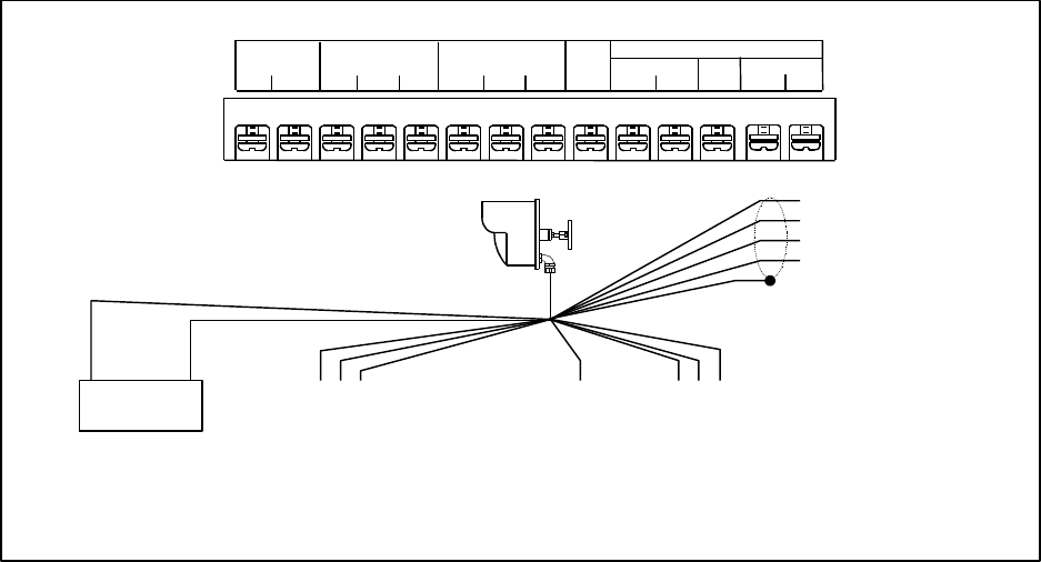
Caution: Do not apply power until all wire connections have been made. See following instructions. Figure 14 shows
physical locations of sensitivity and RCO adjustments, LED indicators and terminal strip.
1) Remove radome of Model 380 Transceiver by removing the six-radome screws.
2) Insert power wires, alarm circuit wires, tamper circuit wires and synchronization wires through conduit fitting.
Leave enough slack in wires so that transceiver may be tilted after radome is replaced.
3) Make connections to the terminal strip according to labeled terminal functions. (See Figure 15.)
4) Attach power wires to terminal identified as +12 VDC (Positive) and GND (Negative). Observe polarity.
5) For protection against unauthorized openings or tampering, a tamper switch with a separate set of contacts is
provided. Normally open and closed contacts are available at "Tamper Switch" terminal.
6) For synchronization, a #22 or #24 gauge twisted shielded pair wire must be connected between the transceivers.
One end of the wire is connected to (+) and (-) master synchronization terminals. The other end connects to (+) and
(-) slave terminal on the second transceiver. Additional slaves would be daisy chained from (+) and (-) slave
terminal (See Figure 11). The last slave unit must be terminated with a 120 ohm 1/4 watt resistor. Set the units to
the appropriate address code with the master set to zero. Set the Sync Switch to “ON” position on master.
POWER LED
LOCK LED
ALARM LED
RANGE CUT-OFF ADJUST SENSITIVITY ADJUST
(Top Front of Enclosure)
ADDRESS SELECT
SWITCH, (CAPPED)
POWER
ALARM
LOCK
ADRS
FUSE 1A
SYNC
SWITCH
TAMPER
SWITCH
16
7) A test function is included in Model 380. When gated on by a +5 to +12 VDC command (at the terminal block),
the test function provides a phantom signal into the transmitter and receiver circuits to generate an alarm and test
the entire 380 detection system.
8) After wiring is complete, it is recommended that entry conduit be filled (sealed) with non-corrosive sealant such as
Dow-Corning #738 RTV. This will prevent moist air in the conduit system from entering Model 380 Transceiver.
Non-corrosive RTV is available from electronic supply distributors or from Southwest Microwave, Inc.
Figure 15
ALIGNMENT AND TEST______________________________________________________
Model 380 requires only Southwest Microwave Model RM82 Performance Test Set for on-site alignment.
1.0 SINGLE UNIT INSTALLATION
1.1 Remove radome.
1.2 Remove dust cap from MS connector located on rear of unit.
1.3 Connect RM82 Test Meter to MS connector.
1.4 Remove cap for access to address switch and set code 0.
1.5 Replace cap.
1.6 Orient Model 380 in direction of required detection zone and apply power.
NOTE: SHIELDED WIRE
RECOMMENDED
NOTE: After wiring is complete, it is recommended that entry conduit be filled
(sealed) with non-corrosive sealant such as Dow Corning #738 RTV. This will
prevent moist air in the conduit system from entering the transmitter or receiver.
TO TAMPER
CIRCUIT
TO ALARM
CIRCUIT
TEST
TO POWER
SUPPLY
TAMPER
SWITCH
COM.
INPUT
12VDC
+-
N.O. N.C.
ALARM
RELAY
COM.N.O. N.C. T
S
E
T
SYNCHRONIZATION
+-+-
D
N
G
12VDC SUPPLY
+-
GND
SLAVE INPUT
MASTER OUTPUT
1 2 3 4 5 6 7 8 9 10 11 12 13 14
MASTER SLAVE

17
1.7 Set RM82 function switch to Power Supply position (this monitors 12 VDC supply). Should read between
0.4 and 0.6.
1.8 Set RM82 function switch Regulated Power Supply position (this checks the internal regulated supply of
the Model 380). Should read between 0.4 and 0.5.
1.9 Set RM82 function switch to Align position and insure reading is between 0.3 and 0.7.
1.10 Set RM82 function switch to Sensitivity position, meter should read between 0.4 and 0.5 (this represents
ambient “no signal” condition. Reflected signals will cause the meter to swing about this point). An alarm
will occur whenever the meter swings to below 0.2 and above 0.8.
1.11 Set alarm selector to Audio and perform a walk test to determine the actual detection pattern.
1.12 Adjust the Range control to provide the required maximum range.
1.13 Adjust the Sensitivity control clockwise to increase the detection pattern width as desired.
1.14 Return the RM82 function switch to the Sensitivity position to be sure that the meter reading remains
stable. Large variations in meter reading can indicate that the sensitivity is set too high, something is
moving or vibrating, or there is interference and may cause nuisance alarms. Recheck the site for moving
or vibrating objects within the detection pattern and possible sources for interference.
1.15 Replace the radome and repeat the walk test.
2.0 MULTIPLE UNIT INSTALLATION
Follow wiring diagram as shown in Figure 11. It is recommended that each sensor be aligned individually. Follow
the procedure outlined in section 1.0 except that the address code in step 1.4 should be set at different channels for
each unit. Insure that the lock light is out at each sensor, except the one designated as the master. This indicates
that the internal oscillator has acquired lock.
Note: Voltages at MS connector pins are:
PIN VOLTAGE FUNCTION
A10.5-14VDC Input Power
B8.5 VDC ± 10% Internal Regulated Supply
C4.0 VDC Typical Alignment
D0Chassis Ground
E4.0 VDC Typical Doppler (Sensitivity)
F0.1 VDC (Normal), Alarm Status
10-12 VDC (Alarm)
PREVENTATIVE MAINTENANCE_______________________________________________
Model 380 requires no calibration other than alignment, RCO and sensitivity adjustment during installation. To
maintain a trouble free system, the following is recommended.
1) Wax the radomes every 3 to 6 months. (At maximum security installations, where detection of prone crawling
targets is required, wax once a month.)
18
2) Keep the isolation area clean and free of tall grass, weeds, debris, obstructions and moving objects.
3) Upon initial installation, establish a zone data chart. Record input supply voltage, zone distance, transceiver
mounting height, alignment voltage, RCO setting, sensitivity setting, address codes and battery voltages.
4) If standby batteries are used, they should be functionally tested every three months.
5) A site inspection should be performed every six months. The inspection should include verifying data from Step
3, checking for physical damage (cracks, leaks, corrosion, etc.), checking for isolation zone changes (washouts,
materials placement, vegetation growth, loose fence fabric, etc.).
6) For troubleshooting information, please contact the factory about Model 380 Service Instructions.
OPTIONAL EQUIPMENT_______________________________________________________
Model PS40 Power Supply operates from 110 VAC, 50-60 Hz, and 0.5A and furnishes 13.7 VDC at up to 1.6A. Model
PS41 Power Supply operates from 220 VAC, 50-60 Hz, and 0.25A. The Power Supply contains automatic switchover
and battery charging circuitry for optional standby batteries of up to 20 AH. Power supplies are fused on both input and
output for maximum protection.
Model PS50 and Model PS51 Power Supply includes a 16.5 VAC, 50-60 Hz, plug-in transformer, Model PT61 or
PT62, and furnishes 13.7 VDC at up to 0.3A from the circuit board. Model PS50 and Model PS51 will charge a standby
battery of up to 6.5 AH. Model PT62 Plug-In Transformer provides 16.5 VAC at 15 VA from input of 110 VAC (for
Model PS50). Model PT61 Plug-In Transformer operates from 220 VAC (for Model PS51).
Rechargeable standby battery available is Model BA30-12.6V 6.5AH jelly acid battery.
Model RM82 Performance Test Set is used for setup and provides for local external monitoring of critical parameters of
Microwave Links or Transceiver manufactured by Southwest Microwave. The Model RM82 is powered from the unit
under test.
Model MB65 Mounting Bracket is a heavy duty, position locking non-corrosive mounting bracket. It provides means of
locking the angular direction setting of Model 380 Transceiver. Model MB65 mounts only to a 4" (10.2cm) O.D. post.
LIMITED WARRANTY__________________________________________________________
Southwest Microwave, Inc. warrants each of its Security Products to be free from defects in materials and workmanship.
The limit of liability under this warranty is to repair or replace any Security Product or part thereof which shall within
one year after delivery to the original user, be returned, shipping costs prepaid and insured, to Southwest Microwave,
Inc., at its plant in Tempe, Arizona, or authorized Warranty Service Company, and which shall have been found to be
defective upon examination by Southwest Microwave, Inc. or authorized Warranty Service Company.
This warranty shall be limited to the repair or replacement of Southwest Microwave, Inc. equipment and shall not extend
to any incidental or consequential damages therefrom. Disassembly of any Security Product by anyone other than an
authorized representative of Southwest Microwave, Inc. voids the obligations of Southwest Microwave, Inc., to repair or
replace any product so disassembled.
Excluded from this warranty, are light bulbs, fuses and batteries except to the extent that the original manufacturer
warrants such parts and such warranty are marked on the product. Claim under warranty for the purchaser should make
light bulbs, fuses or batteries directly to the manufacturer.
Warranty returns must first be authorized by Southwest Microwave, Inc., or an authorized Warranty Service Company.
19
Southwest Microwave, Inc., reserves the right to make changes in design on any of its products without incurring any
obligation to make the same changes on units previously purchased.
This warranty is the extent of the obligations or liabilities assumed by Southwest Microwave, Inc. with respect to
its products and is in lieu of all other warranties, express or implied, including, but not limited to, any warranty
or merchantability or fitness. Southwest Microwave, Inc. shall not be liable for consequential damages and its
liability is expressly limited to the obligations expressed herein. Southwest Microwave, Inc. neither assumes nor
authorizes any other person to assume for it any other warranty concerning its products.
THIS DEVICE COMPLIES WITH FCC RULES PART 15. Operation of this device is subject to the following two
condition: 1. This device may not cause harmful interference. 2. This device must accept any interference that may be
received, including interference that may cause undesired operation.
RETURNING EQUIPMENT UNDER WARRANTY__________________________________
As per the provisions set forth in our security products warranty, any person desiring to return equipment to Southwest
Microwave, Inc. for any reason, must first contact Southwest Microwave, Inc. for authorization of return.
An authorization number will be issued at the time of authorization, and this number will appear on all correspondence,
invoices and credits pertaining to subject equipment.
All Southwest Microwave, Inc. sensors and power supplies are provided with a serial number at the time of manufacture.
In order to accurately and efficiently supply replacement parts, perform repair service, or issue credit on equipment
being returned to Southwest Microwave, Inc. it is essential that Southwest Microwave, Inc. be advised of the serial
number of the equipment prior to authorization for return. This notification may be made by telephone or by mail.
RETURNING EQUIPMENT FOR NON-WARRANTY REPAIR_______________________
Southwest Microwave, Inc., at which time a return authorization number will be issued, must first authorize return of
equipment out of warranty. The returned equipment must be accompanied by an evaluation repair purchase order.
Returned equipment will be examined and customer advised of cost of repair or replacement.
REPLACEMENT PARTS________________________________________________________
To order a replacement or module, specify the complete part number and serial number and address the order to:
SOUTHWEST MICROWAVE, INC.
Service Department
9055 S. McKemy Street
Tempe, Arizona 85284-2946
TEL (480) 783-0201
FAX (480) 783-0401
www.southwestmicrowave.com
infossd@southwestmicrowave.com