Spacelabs Healthcare 670-1187-608 96281-A05N, 96281-A05W, 96281-B05N, 96281-B05W, 96281-C05W User Manual 070 2407 00 Rev A
Spacelabs Healthcare, Inc. 96281-A05N, 96281-A05W, 96281-B05N, 96281-B05W, 96281-C05W 070 2407 00 Rev A
UserManual.wiki
>
Spacelabs Healthcare
>
670 1187 608 User Manual
User Manual
Navigation menu
Upload a User Manual
Namespaces
Wiki Guide
HTML
PDF
Info
Views
User Manual
Discussion / Help
Navigation


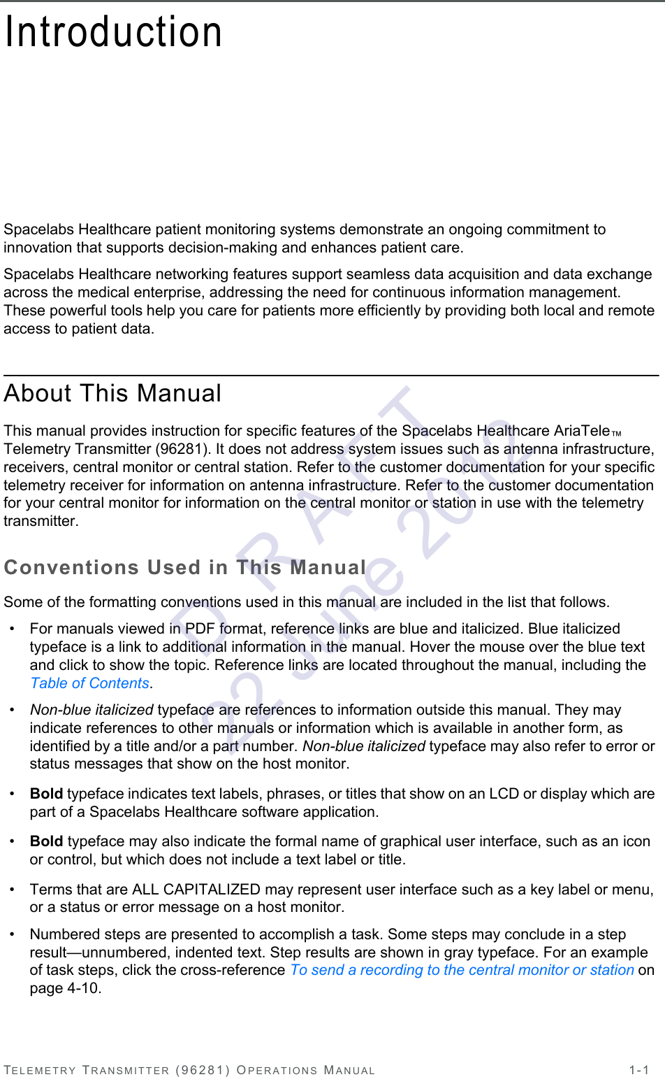

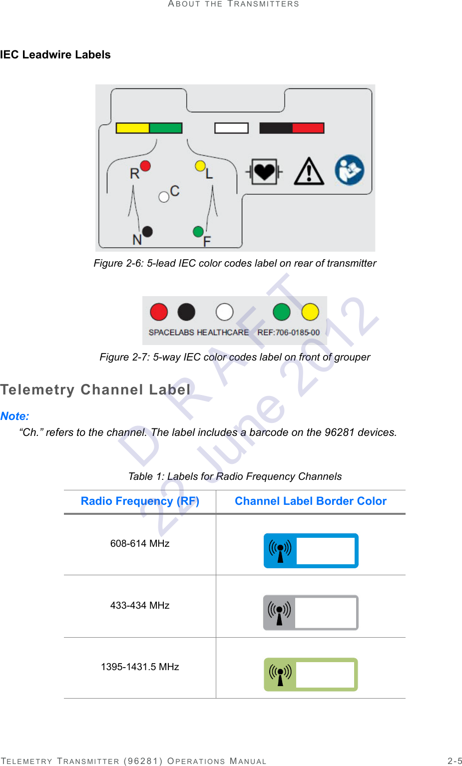

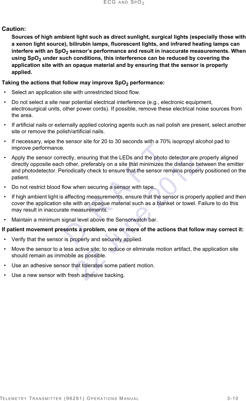
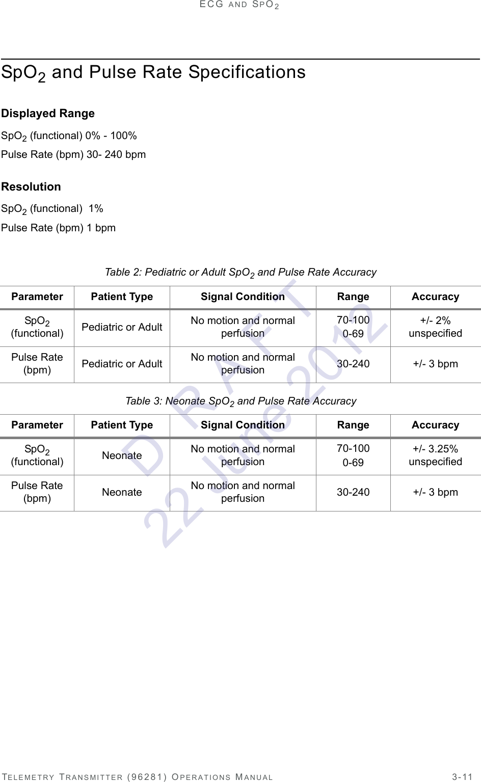
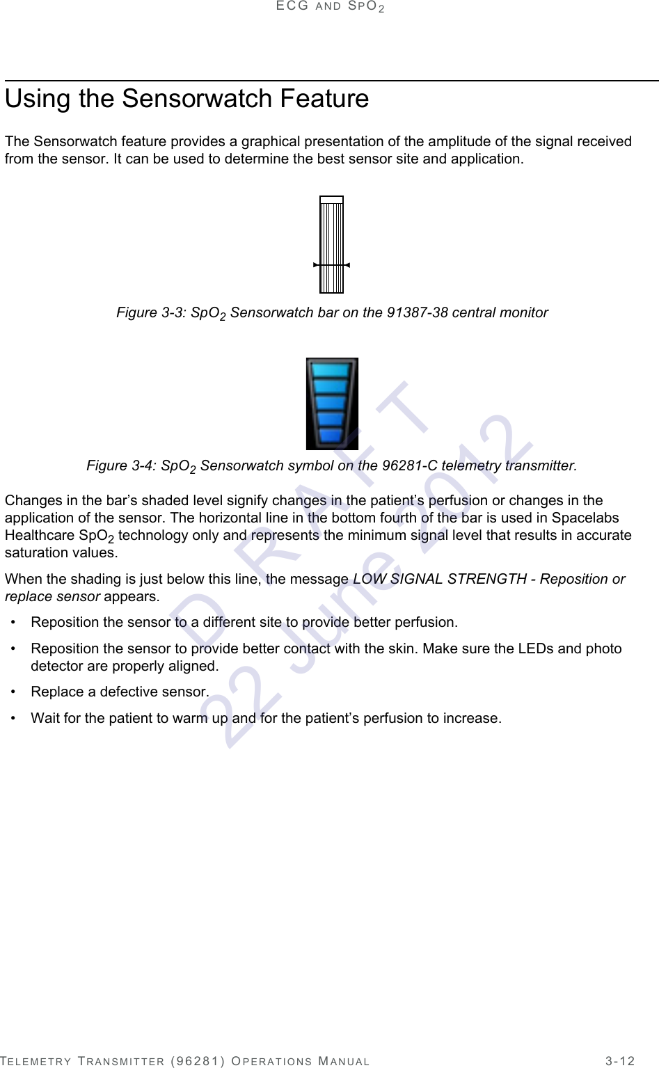
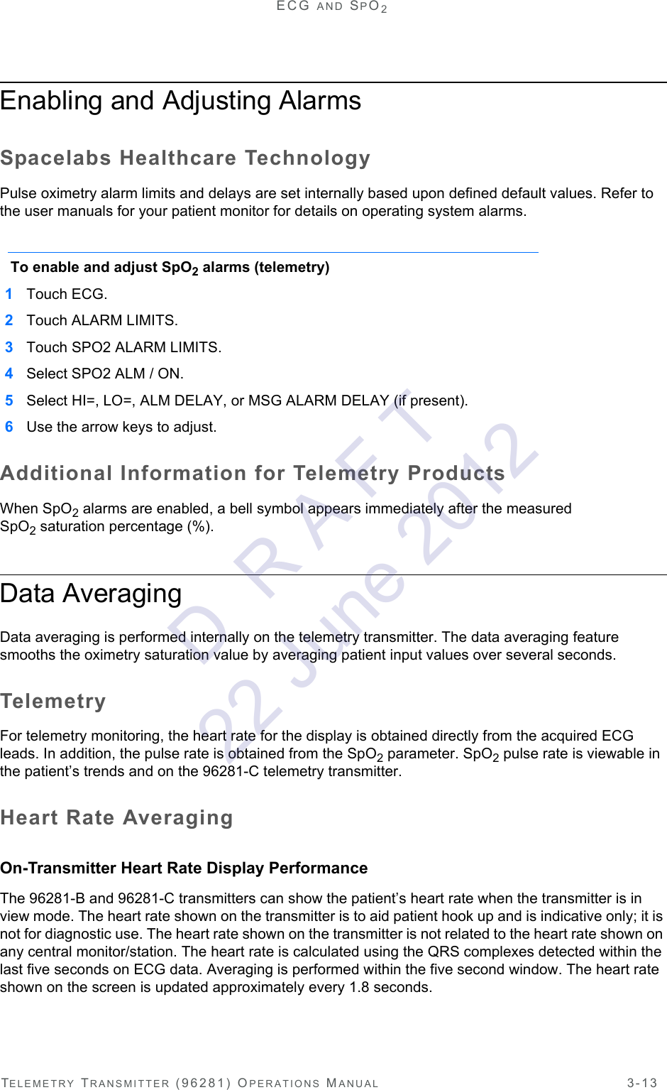

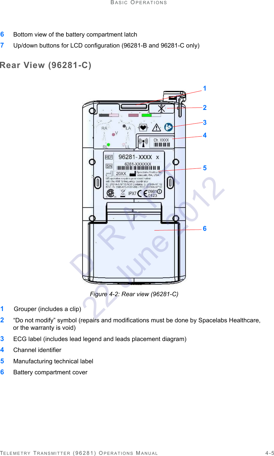
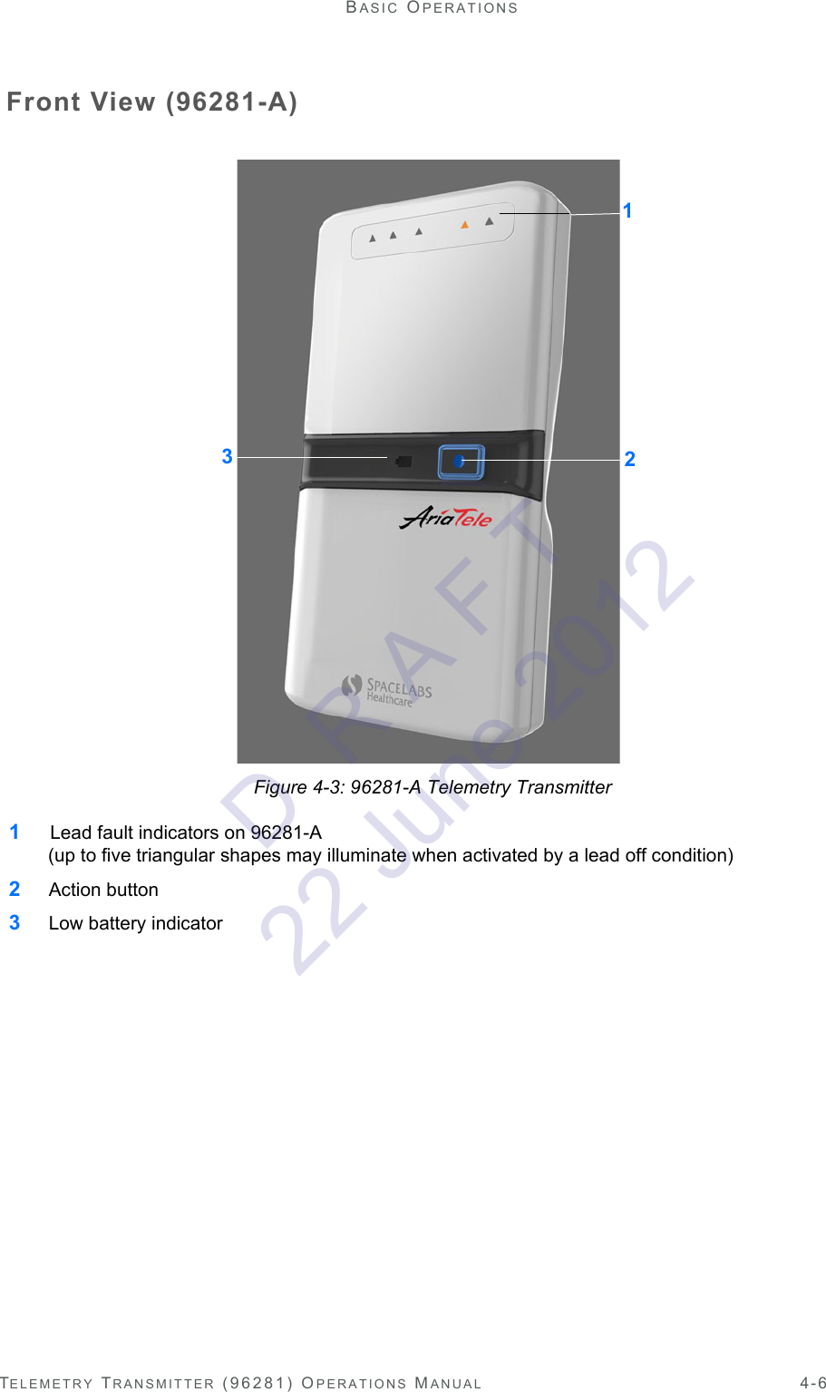
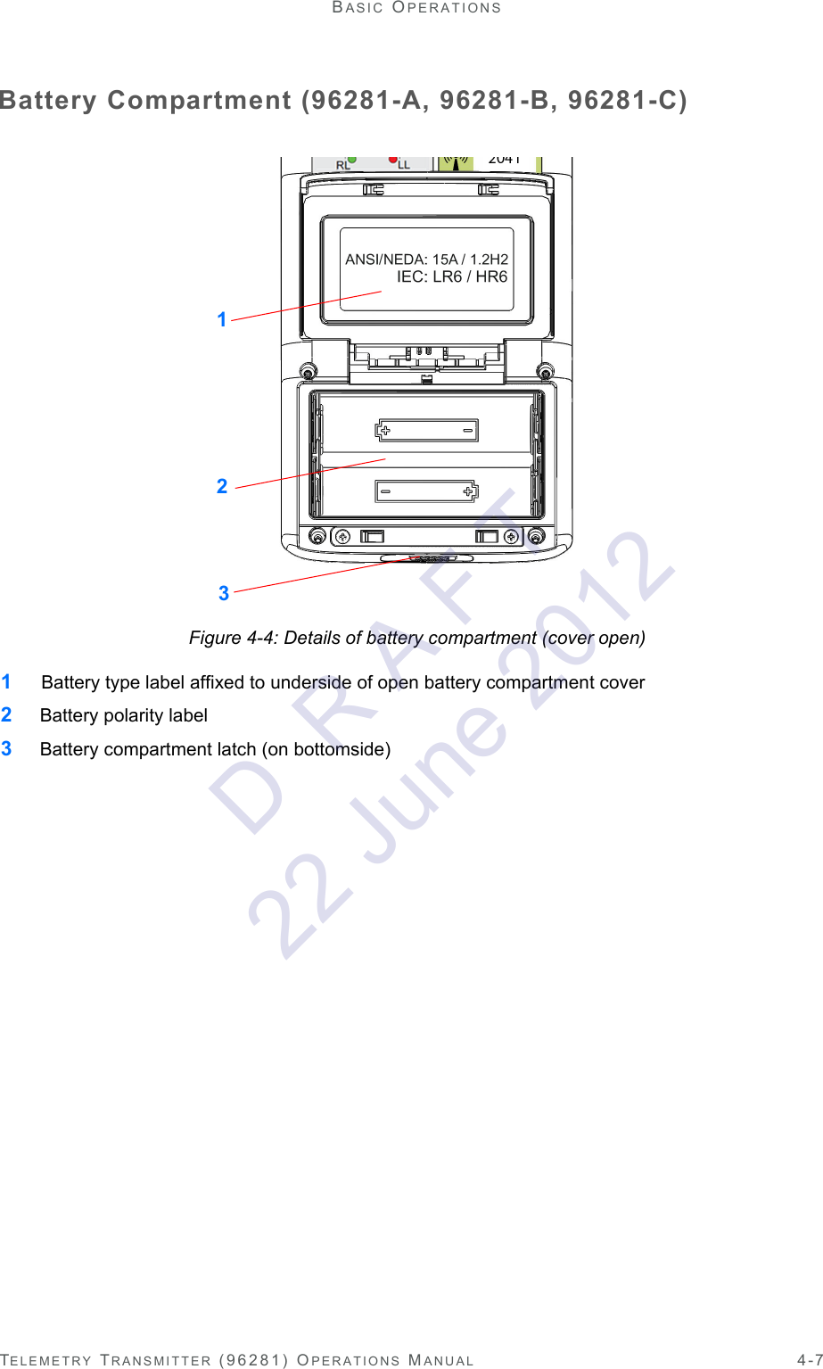
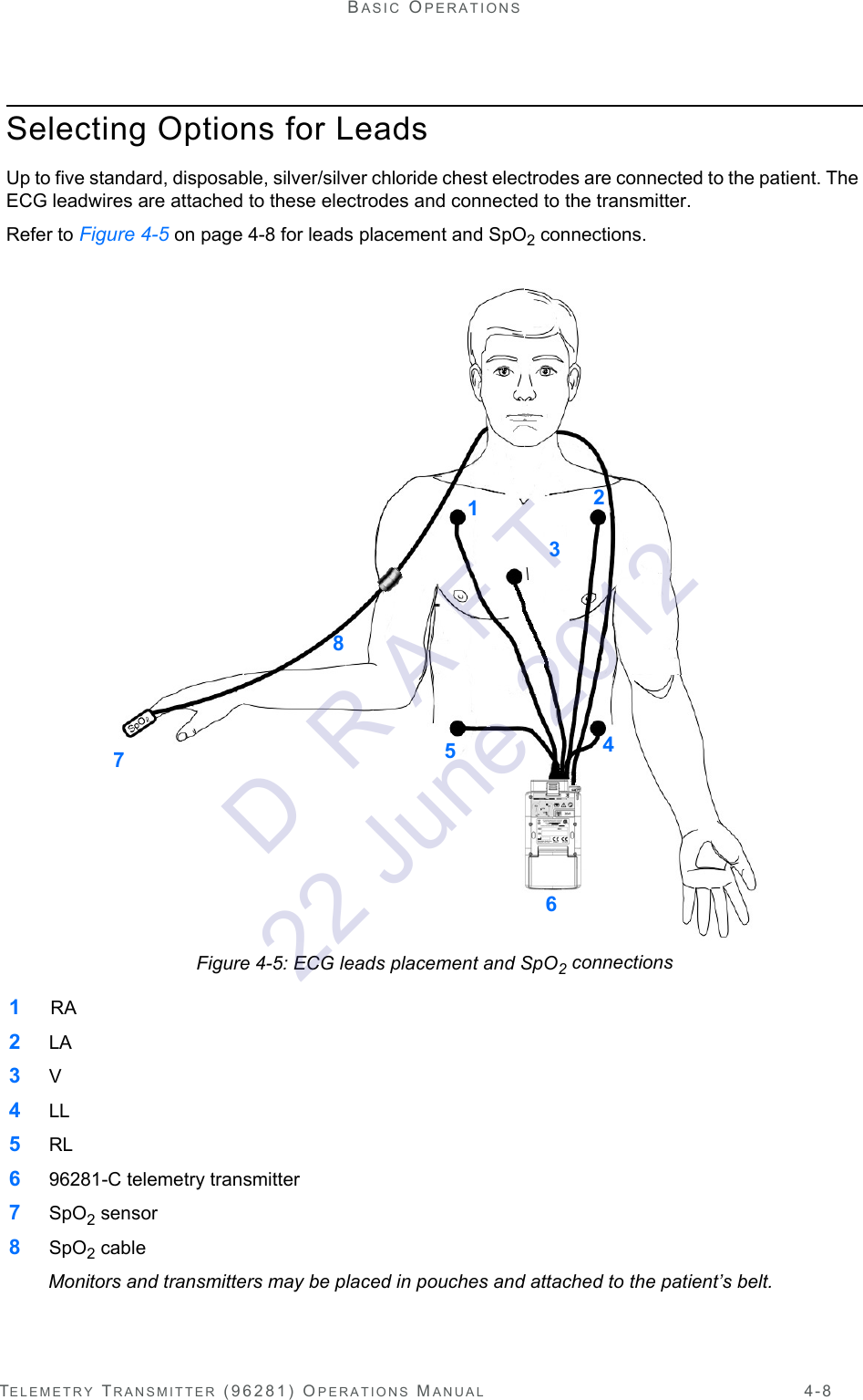
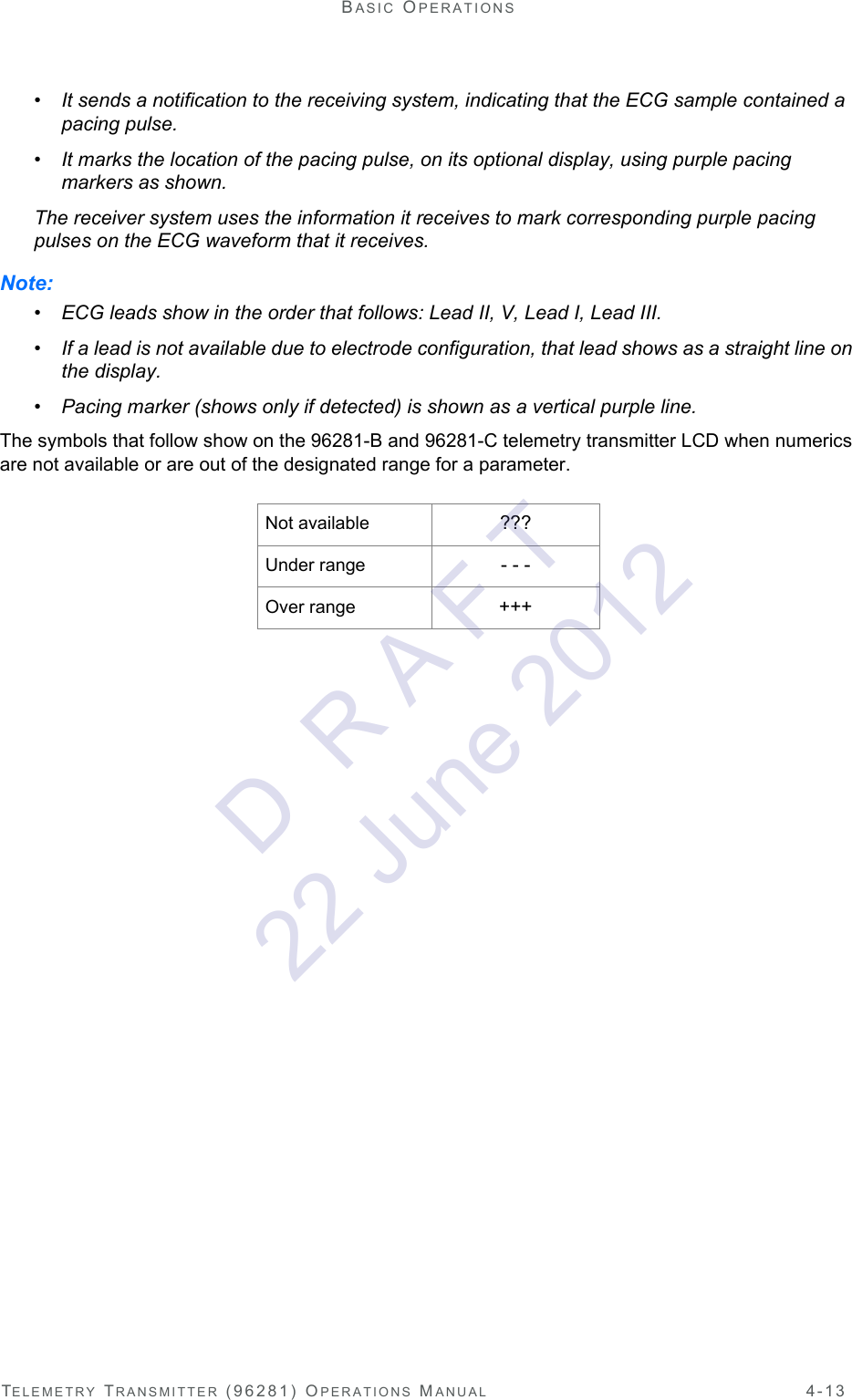
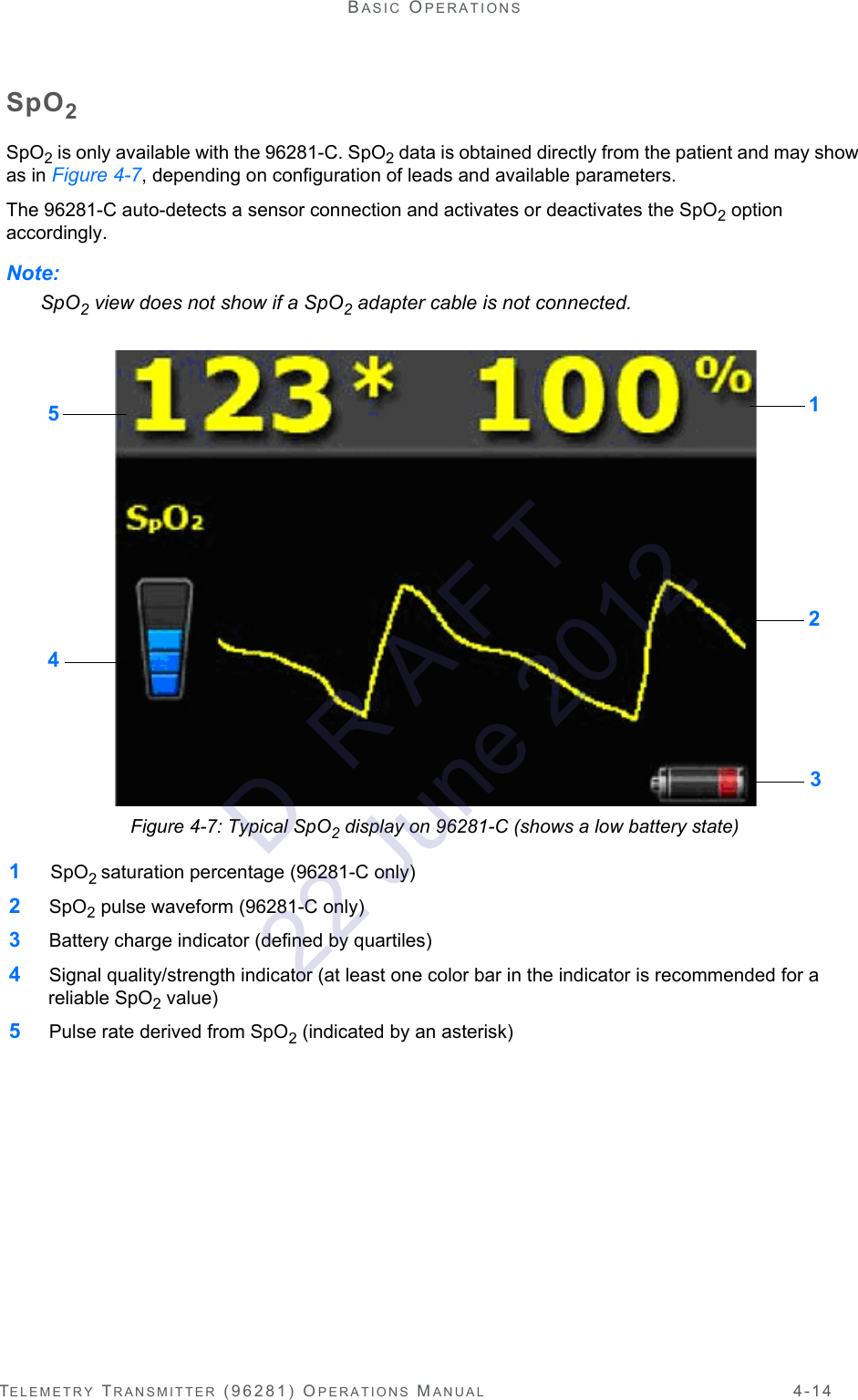
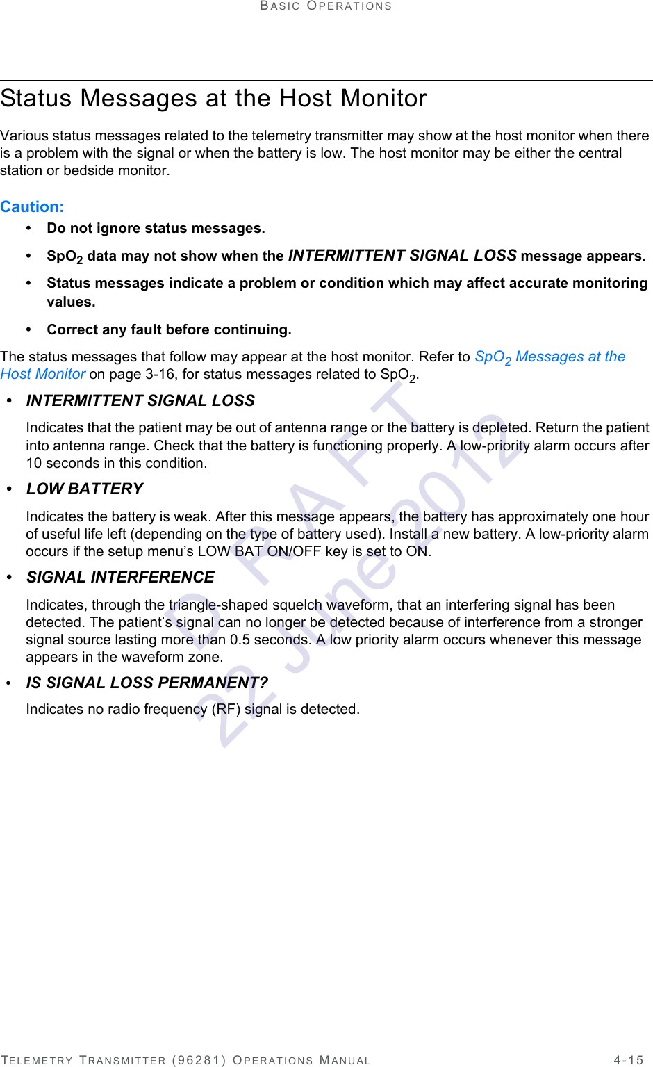
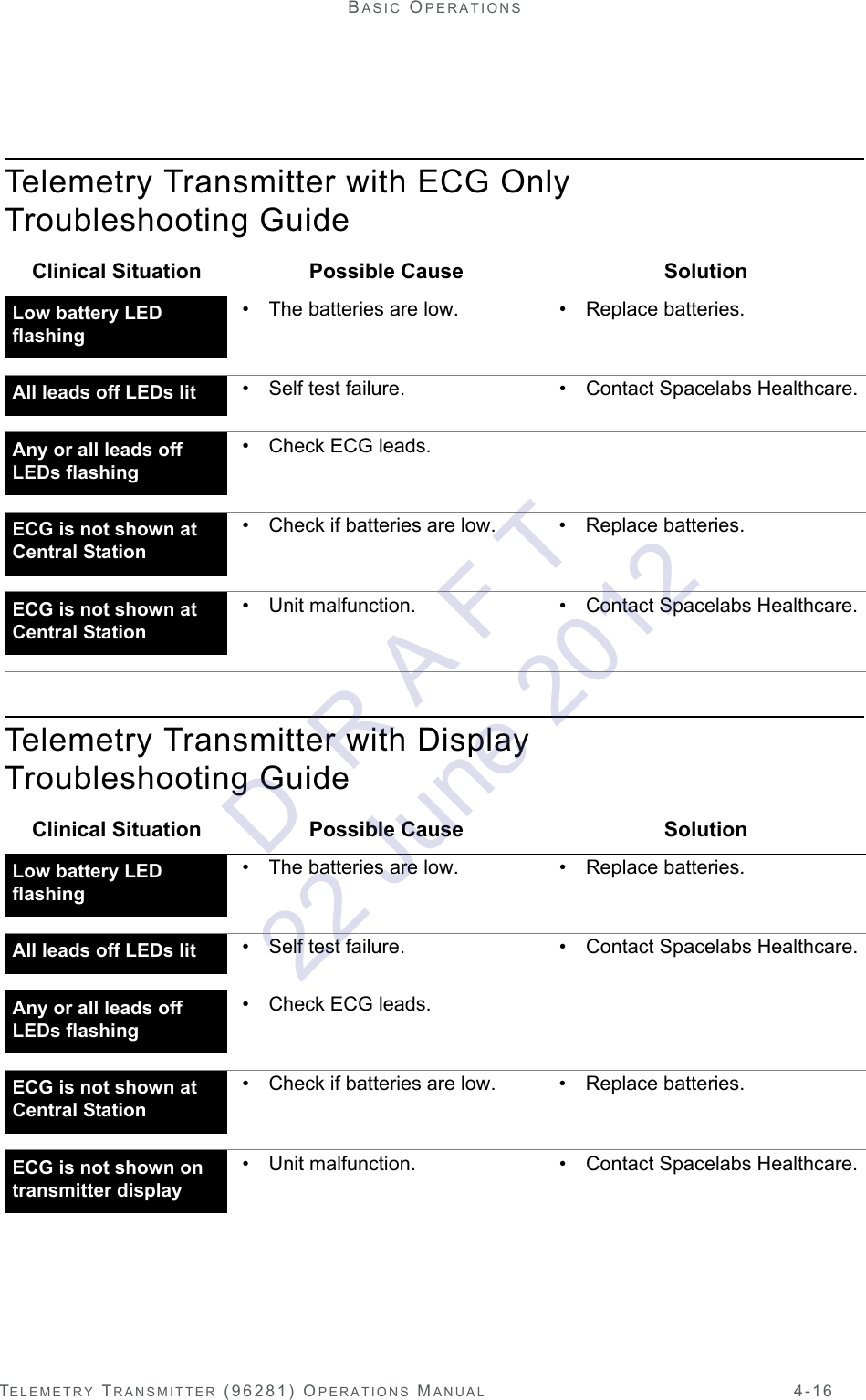


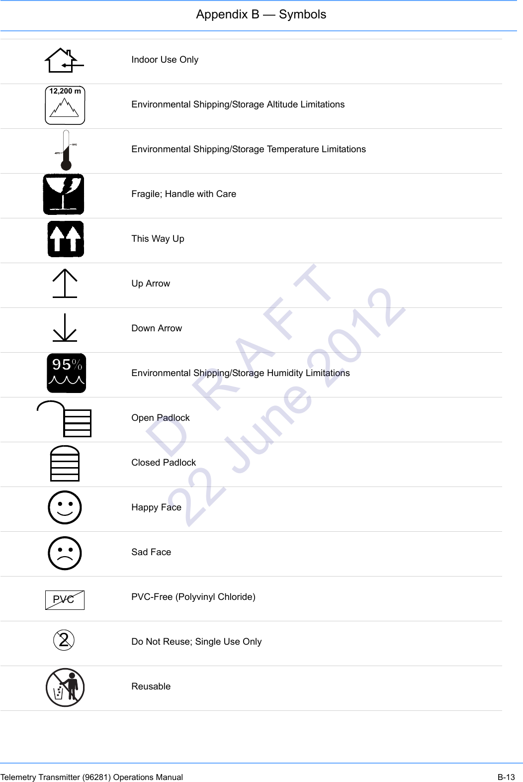
![Appendix B — SymbolsTelemetry Transmitter (96281) Operations Manual B-14Drip-ProofIPX7 Unit can withstand accidental immersion in one meter of water for up to 30 minutesReference Number or Order NumberUse by date [YYYY-MM-DD]RecycleNon SterileLatex-FreeDate of ManufactureManufacturerRadio transmitting device; elevated levels of non-ionizing radiationA CE mark certifies that a product has met EU health, safety, and environmental requirements, which ensure consumer safety. XXXX is the European Notified Body number. 0123 is the number for TÜV SÜD Product Service GmbH, München, Germany.Canadian Standards Association ApprovedBatch CodeNellcor Oxisensor II CompatibleREFXXXX®C ULOTNE2D R A F T 22 June 2012](https://usermanual.wiki/Spacelabs-Healthcare/670-1187-608/User-Guide-1745342-Page-86.png)