Spacelabs Healthcare 76A91341-600 91341-05 User Manual Exhibit H 2
Spacelabs Healthcare, Inc. 91341-05 Exhibit H 2
Contents
- 1. User Manual 1
- 2. User Manual 2
User Manual 2
Exhibit H: User Manual 2
FCC ID: CM676A91341-600

Ultraview Digital Telemetry
91341 / 91343 / 91347
Operations Manual
071-0774-00 Rev. A
®

Copyright 2002 Spacelabs Medical, Inc.
All rights reserved. Contents of this publication may not be reproduced in any form without the written permission of Spacelabs
Medical, Inc. Products of Spacelabs Medical are covered by U.S. and foreign patents and/or pending patents. Printed in U.S.A.
Specifications and price change privileges are reserved.
Spacelabs Medical considers itself responsible for the effects on safety, reliability and performance of the equipment only if:
• assembly operations, re-adjustments, modifications or repairs are carried out by persons authorized by Spacelabs
Medical, and
• the electrical installation of the relevant room complies with the requirements of the standard in force, and
• the equipment is used in accordance with the operations manual.
Spacelabs Medical will make available, on request, such circuit diagrams, component part lists, descriptions, calibration instructions
or other information which will assist appropriately qualified technical personnel to repair those parts of the equipment which are
classified by Spacelabs Medical as field repairable.
Spacelabs Medical, Inc.
15220 N.E. 40th Street
P.O. Box 97013
Redmond, WA 98073-9713
U.S.A.
Telephone: 425-882-3700
Fax: 425-885-4877
Telex: 4740085 SPL UI
Spacelabs Medical Products Pty. Ltd.
Macquarie View Estates
Unit 1, 112-118 Talavera Road
North Ryde, N.S.W. 2113
AUSTRALIA
Telephone: 61-2-9878-6644
Fax: 61-2-9878-4820
Spacelabs Medical Products GmbH
Jochen Rindt Straße 25
1230 Vienna
AUSTRIA
Telephone: 43-1-616 52 37
Fax: 43-1-616 52 37 11
Spacelabs Medical B.V.
Airport Boulevard Office Park
Bessenveldstraat 25A
1831 Diegem
BELGIUM
Telephone: 32 2 7164026
Fax: 32 2 7164114
Spacelabs Medical Products, Ltd.
151 Superior Boulevard, Unit 1
Mississauga, Ontario L5T 2L1
CANADA
Telephone: 905-670-5880
Fax: 905-670-5883
CORPORATE OFFICES
Spacelabs Medical Instruments
(Tianjin) Co. Ltd.
6th Floor, Wang Jing Building
9 Wang Jing Zhong Huan South Road
Cho Yang District, Beijing 100015
CHINA
Telephone: 86-10-64731705
Fax: 86-10-64721707
Authorized EC Representative:
Spacelabs Medical Sarl
6, Allée des Saules
Europarc
94042 Créteil Cedex
FRANCE
Telephone: 33 (0) 1 45.13.22.44
Fax: 33 (0) 1 45.13.22.00
Spacelabs Medical GmbH
Airport Park
Willicher Damm 121+123
41066 Mönchengladbach
GERMANY
Telephone: 49-2161-8209-0
Fax: 49-2161-8209-222
Spacelabs Medical Limited
Suite 901 Tower 1
China Hong Kong City
33 Canton Road, Tsimshatsui
Kowloon
HONG KONG
Telephone: 852-2376-1370
Fax: 852-2376-2502
Spacelabs Medical, Inc.
c/o Impulse Business Club
F-22 South Extension Part 1
New Delhi 110049
INDIA
Telephone: 911 1464 5002
Fax: 911 4603338
Spacelabs Medical S.r.l.
Via Montecatini, 13
20144 Milano
ITALY
Telephone: 39-0-2/48958203
Fax: 39-0-2/48958204
Spacelabs Medical Ltd.
2F-3, No. 161. Sung Te Road
Taipei, Taiwan R.O.C.
TAIWAN
Telephone: 8862-2759-7238
Fax: 8862-2759-9060
Spacelabs Medical B.V.
Ringveste 9 A
3992 DD Houten
THE NETHERLANDS
Telephone: 31-(0)-30-638 5050
Fax: 31-(0)-30-638 5059
Spacelabs Medical Ltd.
Indigo Building
Unit 9, Mulberry Business Park
Fishponds Road
Wokingham, Berkshire RG 41 2GY
UNITED KINGDOM
Telephone: 44 118 9773 100
Fax: 44 118 9798 200
CAUTION:
• US Federal law restricts the devices documented herein to sale by, or on the order of, a
physician.

Spacelabs Medical is committed to providing comprehensive customer support beginning with your initial inquiry through
purchase, training, and service for the life of your Spacelabs Medical equipment. If you need our help along the way, we
offer these guidelines for fast, efficient response.
Acquiring Equipment
Sales Representative
800-522-7025 (U.S.A.)
or call your local office
To discuss your monitoring or clinical information
needs, to schedule product demonstrations, to order
equipment, or to schedule in-service education
Delivery Information
800-251-9910 (U.S.A.)
or call your local office
To find out when you can expect delivery of your
Spacelabs Medical equipment
Supplies Products
800-223-6467 (U.S.A.)
or call your local office
To order compatible supplies and accessories for your
equipment
Getting Started
Sales Representative
800-522-7025 (U.S.A.)
or call your local office
To arrange in-service education sessions
Answering Other Needs
Clinical Applications
800-522-7025 (U.S.A.) or 425-882-3700
or call your local office
To answer specific questions on arrhythmia products
and clinically related issues
First CallSM National Dispatch Center
800-522-7025 (U.S.A.)
800-942-7968 (Canada)
To call for service or to contact your assigned customer
service representative
Technical Support - Monitoring/Anesthesia
800-522-7025 (U.S.A.) or 425-882-3700
or call your local office
For technical support of all Ultraview® Care Network™
monitoring products and anesthesia products
Technical Support - Intesys Clinical Information Systems
800-210-0247 (U.S.A.) or 425-882-3700
or call your local office
For technical support of BirthNet®, Caremaster®,
Chartmaster®, QuIC, and WinDNA® products
Service Parts Department
800-547-8805 (U.S.A.) or 425-867-2039
or call your local office
For parts ordering and pricing information
Service Training Department
800-251-9910 (U.S.A.)
or call your local office
To arrange training of hospital biomedical and
anesthesia personnel
Regional Service Manager
800-522-7025 (U.S.A.)
800-942-7968 (Canada)
or call your local office
To obtain answers to general questions concerning
service issues and service contracts
Contacting Your Local Offices Outside the U.S.
Mississauga, Ontario
Canada
905-670-5880
Mönchengladbach
Germany
49-2161-8209-0
Kowloon
Hong Kong
852-2376-1370
Taipei
Taiwan
8862-2759-7238
Créteil
France
33 (0)1 45.13.22.44
Vienna
Austria
43-1-616 52 37
Milano
Italy
39-0-2/48958203
Beijing
China
86-10-64731705
Wokingham, Berkshire
U.K.
44 118 9773 100
New Delhi
India
911 1464 5002
Diegem
Belgium
32 2 7164026
Houten,
The Netherlands
31-(0)-30 638 5050

071-0774-00 Rev. A i
Chapter Page
1Contents
Introduction
Directory of Keys - UCW and Ultraview 1700 . . . . . . . . . . . . . . . . . . . . . . . . . . . . . . . . . . . . . 1-1
Overview . . . . . . . . . . . . . . . . . . . . . . . . . . . . . . . . . . . . . . . . . . . . . . . . . . . . . . . . . . . . . . . . . 1-2
Cleaning . . . . . . . . . . . . . . . . . . . . . . . . . . . . . . . . . . . . . . . . . . . . . . . . . . . . . . . . . . . . . . . . . 1-9
Assigning a Telemetry Channel . . . . . . . . . . . . . . . . . . . . . . . . . . . . . . . . . . . . . . . . . . . . . . . 1-9
Tuning a Receiver for a Bedside . . . . . . . . . . . . . . . . . . . . . . . . . . . . . . . . . . . . . . . . . . . . . . . 1-9
Entering Patient Information . . . . . . . . . . . . . . . . . . . . . . . . . . . . . . . . . . . . . . . . . . . . . . . . . 1-10
Discharging a Patient . . . . . . . . . . . . . . . . . . . . . . . . . . . . . . . . . . . . . . . . . . . . . . . . . . . . . . 1-10
Acknowledging Signal Loss. . . . . . . . . . . . . . . . . . . . . . . . . . . . . . . . . . . . . . . . . . . . . . . . . . 1-11
Setting Battery Status Alarms . . . . . . . . . . . . . . . . . . . . . . . . . . . . . . . . . . . . . . . . . . . . . . . . 1-11
Controlling Patient-Initiated Recordings . . . . . . . . . . . . . . . . . . . . . . . . . . . . . . . . . . . . . . . . 1-11
Telemetry Alarm Message Summary . . . . . . . . . . . . . . . . . . . . . . . . . . . . . . . . . . . . . . . . . . 1-11
Accessories . . . . . . . . . . . . . . . . . . . . . . . . . . . . . . . . . . . . . . . . . . . . . . . . . . . . . . . . . . . . . . 1-12
ECG
Overview . . . . . . . . . . . . . . . . . . . . . . . . . . . . . . . . . . . . . . . . . . . . . . . . . . . . . . . . . . . . . . . . . 2-1
Setting Up ECG Monitoring . . . . . . . . . . . . . . . . . . . . . . . . . . . . . . . . . . . . . . . . . . . . . . . . . . . 2-1
Display Detail . . . . . . . . . . . . . . . . . . . . . . . . . . . . . . . . . . . . . . . . . . . . . . . . . . . . . . . . . . . . . 2-4
Monitoring Paced ECG Patients . . . . . . . . . . . . . . . . . . . . . . . . . . . . . . . . . . . . . . . . . . . . . . . 2-5
Restoring Default Settings. . . . . . . . . . . . . . . . . . . . . . . . . . . . . . . . . . . . . . . . . . . . . . . . . . . . 2-6
Changing the Display Resolution . . . . . . . . . . . . . . . . . . . . . . . . . . . . . . . . . . . . . . . . . . . . . . 2-6
Selecting Options for Lead Display . . . . . . . . . . . . . . . . . . . . . . . . . . . . . . . . . . . . . . . . . . . . . 2-7
ECG Alarm Message Summary . . . . . . . . . . . . . . . . . . . . . . . . . . . . . . . . . . . . . . . . . . . . . . . 2-9
SpO2 (91343 only)
Overview . . . . . . . . . . . . . . . . . . . . . . . . . . . . . . . . . . . . . . . . . . . . . . . . . . . . . . . . . . . . . . . . . 3-1
Setting Up SpO2 Monitoring . . . . . . . . . . . . . . . . . . . . . . . . . . . . . . . . . . . . . . . . . . . . . . . . . . 3-2
Ensuring Accurate Monitoring . . . . . . . . . . . . . . . . . . . . . . . . . . . . . . . . . . . . . . . . . . . . . . . . . 3-3
Setting or Adjusting Alarm Limits . . . . . . . . . . . . . . . . . . . . . . . . . . . . . . . . . . . . . . . . . . . . . . 3-4
Setting SpO2 Data Averaging Period and Sampling Interval . . . . . . . . . . . . . . . . . . . . . . . . . 3-6
Viewing Pulse Rate . . . . . . . . . . . . . . . . . . . . . . . . . . . . . . . . . . . . . . . . . . . . . . . . . . . . . . . . . 3-7
SpO2 with Intra-Aortic Balloon Pumps . . . . . . . . . . . . . . . . . . . . . . . . . . . . . . . . . . . . . . . . . . 3-7
Using SpO2 with Neonates . . . . . . . . . . . . . . . . . . . . . . . . . . . . . . . . . . . . . . . . . . . . . . . . . . . 3-8
SpO2 Alarm Message Summary. . . . . . . . . . . . . . . . . . . . . . . . . . . . . . . . . . . . . . . . . . . . . . . 3-8
NIBP (91343 only)
Overview . . . . . . . . . . . . . . . . . . . . . . . . . . . . . . . . . . . . . . . . . . . . . . . . . . . . . . . . . . . . . . . . . 4-1
Setting Up NIBP Monitoring . . . . . . . . . . . . . . . . . . . . . . . . . . . . . . . . . . . . . . . . . . . . . . . . . . 4-2
Setting Up the ABP Monitor . . . . . . . . . . . . . . . . . . . . . . . . . . . . . . . . . . . . . . . . . . . . . . . . . . 4-3
Setting or Adjusting Alarm Limits . . . . . . . . . . . . . . . . . . . . . . . . . . . . . . . . . . . . . . . . . . . . . . 4-7
Displaying New or Previous Readings . . . . . . . . . . . . . . . . . . . . . . . . . . . . . . . . . . . . . . . . . . 4-8
NIBP Alarm Message Summary . . . . . . . . . . . . . . . . . . . . . . . . . . . . . . . . . . . . . . . . . . . . . . . 4-9

Ultraview Care Network
ii 071-0774-00 Rev. A
Alarms
Alarm Message Summary . . . . . . . . . . . . . . . . . . . . . . . . . . . . . . . . . . . . . . . . . . . . . . . . . . . 5-1
ECG Alarm Messages . . . . . . . . . . . . . . . . . . . . . . . . . . . . . . . . . . . . . . . . . . . . . . . . . . . . . . 5-2
SpO2 Alarm Messages. . . . . . . . . . . . . . . . . . . . . . . . . . . . . . . . . . . . . . . . . . . . . . . . . . . . . . 5-3
NIBP Alarm Messages . . . . . . . . . . . . . . . . . . . . . . . . . . . . . . . . . . . . . . . . . . . . . . . . . . . . . . 5-4
Telemetry Alarm Messages . . . . . . . . . . . . . . . . . . . . . . . . . . . . . . . . . . . . . . . . . . . . . . . . . . 5-5
Symbols
1
071-0774-00 Rev. A 1-1
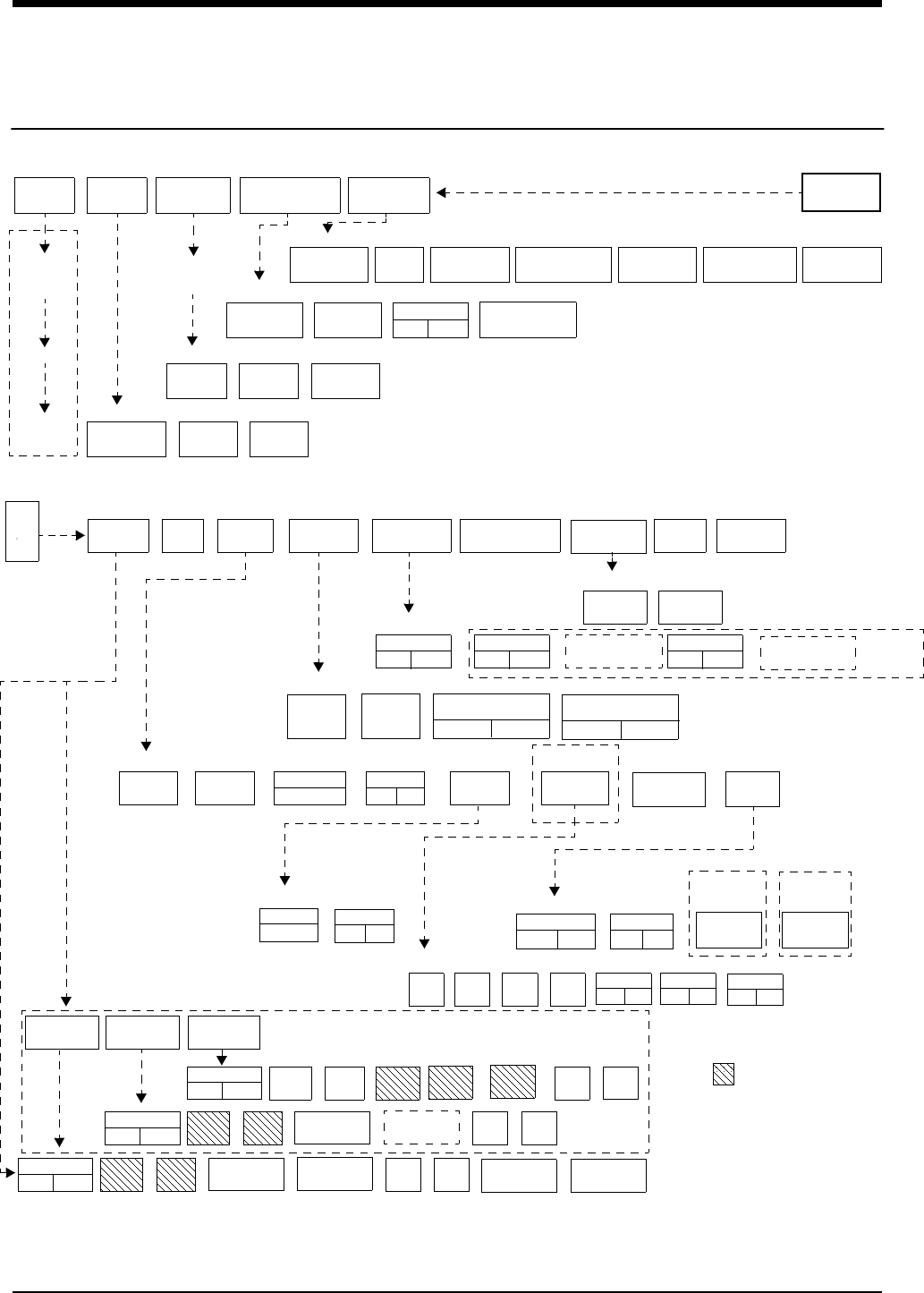
!• Based on features purchased, more or fewer keys may appear here than on your menu screens.
!• Based on features purchased, more or fewer keys may appear here than on your menu screens.
SCREEN
FORMAT TONES MONITOR
CONFIGURATION
PRIVILEGED
ACCESS.
MONITOR
SETUP
CONTRASTBRIGHTNESS
ADMIT CHANGE
DATA DISCHARGE
SCALED
DISPLAY
TIME/
DATE
REMOTE
ALARMS
ALARM
WATCH
KEY
TONE
CLINICAL LEVEL: Select Parameter
MONITOR CONFIGURATION
ADMIT/DISCHARGE - Select Function (see Admit/Discharge)
MONITOR SETUP - Select type of tone to change (see Alarms)
MONITOR SETUP
E
C
G
CLEAR
MEMORY
SAVE
MEMORY
ECG - RELEARN
2nd LEAD
ON OFF
RATE
SOURCE
SWEEP
SPEED
QRS MONITOR PA CED
YES NO CONFIG
TONE EXTENDED
ADULT
INFANT
Select primary heart rate source
ECG - CHANNEL FORMAT
ECG - SETUP
ECG - CONFIG
ALARM
LIMITS SIZE SETUP LEAD
SELECT
CHANNEL
FORMAT
SUSPEND
PROCESSING PRINT
ECG MENU - (Multi-Lead) (MultiviewTM II option with Arrhythmia and Review ON - used with 91343/91347 transmitter)
REVIEW
2nd LEAD
xx
1st LEAD
xx ON OFF
ECG ART UA SPO2
Enable alternate rate source(s)
ARR
ON OFF
UA
ON OFF
ART
ON OFF
SPO2
ON OFF
TM
SETUP
RESTORE
SETTINGS
AUTO LEAD SWITCH
ASSIGN
TM BED
PT RECORD
YES NO
LO BAT
ON OFF
SET TM
CHAN
ECG - TM SETUP
Central
only
Bedside
only
Bedside
monitors only
select bed
(or subnet,
then bed)
RELEARN
SpO2
ON OFF
NIBP
ON OFF
SpO2(IABP)(NEO)
(RATE)(AVG)
91343 only
ECG ALM
ON OFF
ST LIMITS
CH 1
ABN IN
ROW=XX
ABN PER
MIN=XX
↑
ST LIMITS
CH 2
ABN IN
ROW=XX
HI=
XXX
LO=
XXX
SPO2 ALM
ON OFF
ALM DELAY
=XXs
MSG ALM
DELAY =XXs
↑
↓
HI=
XXX
LO=
XXX
NIBP ALM
ON OFF
↑
↓
HI=
XXX
LO=
XXX
NIBP ACTIVE
(NO CABLE)
SPO2 ALARM
LIMITS
NIBP ALARM
LIMITS
LIMITS
91347
(and
91343
with
SpO2
and
NIBP
turned
OFF)
91343
select ECG 1
Select
zone
waveform
select bed
(or subnet,
then bed)
RECORDER
DESTINATION
ECG - LEAD SELECT
ON OFF
SINGLE LEAD ALARM
ECG ALARM
CLOCK
ON OFF
ACTIVATE
SCREEN SAVER
PRESELECTED
RECORDINGS
UNITS OF
MEASURE
USER ACCESS
ENABLE
ALARM
SETUP
ADMIT/
DISCHARGE
MPT=ON*
91343 only MPT=ON*
* Multi-parameter Telemetry (MPT):
required settings in
Module Configuration Manager
↑
DIA MEAN
SYS Limit keys will flash on alarm
Directory of Keys - UCW and Ultraview 1700
1Introduction

1-2 071-0774-00 Rev. A
Contents
1
1Introduction
Overview
The 90478-A digital telemetry receiver module, when used in conjunction with
Spacelabs Medical telemetry transmitters, an Ultraview or PCMS™ monitor, and
90479-A modular receiver housing, provides continuous monitoring of
electrocardiographic signals in order to detect abnormal cardiac rhythms,
including asystole, ventricular fibrillation, and ventricular tachycardia. In addition,
when used with the 91343 digital telemetry multi-parameter transmitter and the
90217 Ambulatory Blood Pressure (ABP) monitor, monitoring of
electrocardiographic signals is augmented by the availability of continuous or
episodic SpO2 measurements and episodic noninvasive blood pressure (NIBP)
measurements.
Directory of Keys - UCW and Ultraview 1700 . . . . . . . . . . . . . . . . . . . . . . . . . . .1
Overview . . . . . . . . . . . . . . . . . . . . . . . . . . . . . . . . . . . . . . . . . . . . . . . . . . . . . . .2
Cleaning . . . . . . . . . . . . . . . . . . . . . . . . . . . . . . . . . . . . . . . . . . . . . . . . . . . . . . .9
Assigning a Telemetry Channel . . . . . . . . . . . . . . . . . . . . . . . . . . . . . . . . . . . . .9
Tuning a Receiver for a Bedside. . . . . . . . . . . . . . . . . . . . . . . . . . . . . . . . . . . . .9
Entering Patient Information . . . . . . . . . . . . . . . . . . . . . . . . . . . . . . . . . . . . . . .10
Discharging a Patient . . . . . . . . . . . . . . . . . . . . . . . . . . . . . . . . . . . . . . . . . . . .10
Acknowledging Signal Loss . . . . . . . . . . . . . . . . . . . . . . . . . . . . . . . . . . . . . . .11
Setting Battery Status Alarms . . . . . . . . . . . . . . . . . . . . . . . . . . . . . . . . . . . . . .11
Controlling Patient-Initiated Recordings . . . . . . . . . . . . . . . . . . . . . . . . . . . . . .11
Telemetry Alarm Message Summary . . . . . . . . . . . . . . . . . . . . . . . . . . . . . . . .11
Accessories. . . . . . . . . . . . . . . . . . . . . . . . . . . . . . . . . . . . . . . . . . . . . . . . . . . .12

Introduction
071-0774-00 Rev. A 1-3
Intended Use
As an option, on adult patients, additional abnormal cardiac rhythms, such as
ventricular runs, tachycardia, and ST segment deviations can be detected. The
Ultraview Digital Telemetry System also provides a means for the episodic
monitoring of NIBP signals to detect abnormal events such as high and low blood
!• Spacelabs Medical’s telemetry equipment complies with Part 15
and Part 95 of the FCC Rules and with RSS-210 of Industry
Canada and with requirements of other national spectrum
management authorities. Repeated here are operational
cautions for biomedical telemetry from the FCC Rules
(47CFR15.242(f)):
“Biomedical telemetry devices must not cause harmful
interference to licensed TV broadcast stations or to other
authorized radio services, such as operations on the
broadcast frequencies under subpart G and H of part 74 of
this chapter, land mobile stations operating under part 90 of
this chapter in the 470-512 MHz band, and radio astronomy
operation in the 608-614 MHz band. (See section 15.5). If
harmful interference occurs, the interference must either be
corrected or the device must immediately cease operation
on the occupied frequency. Further, the operator of the
biomedical telemetry device must accept whatever level of
intereference is received from other radio operations. The
operator (health care facility) is responsible for resolving
any interference that occurs subsequent to the installation
of these devices.”
• Medical telemetry equipment is only for installation and use in
hospitals and health care facilities. It is not permitted for use in
vehicles that operate outside of the medical facility premises.
The user of this equipment is not authorized to make any
changes or alterations that could compromise the national
certifications.
• Operation of telemetry equipment in the 608 - 614 MHz, 1395 -
1400 MHz, 1427 - 1429.5 MHz, and 1429.5 - 1432 MHz parts of
the Wireless Medical Telemetry Service (WMTS) and in
authorized spectrum of each country, may be geographically
restricted by government regulation. Spacelabs Medical
Customer Service can assist in evaluating if a hospital’s location
requires coordination with a protected radio astronomy
observatory or other protected government site that may be
within an 80-km (54-mile) radius.
WARNING:
• Changes or modifications not expressly approved by
Spacelabs Medical will void the user’s authority to operate
the equipment.

Ultraview Digital Telemetry
1-4 071-0774-00 Rev. A
pressure. Finally, it provides a means for both continuous and episodic monitoring
of pulse blood oxygen saturation signals in order to detect oxygen desaturation
caused by abnormal pulmonary/circulatory functions.
The Spacelabs Medical 91341, 91343, and 91347 Ultraview Digital Telemetry
Systems are intended for use with either adult or neonatal patients in a hospital
environment. When the NIBP option is selected in the 91343 configuration, the
NIBP feature is to be used with adult patients only.
Transmitters
The transmitter is a small, battery-powered device carried by the patient that
monitors ECG activity and SpO2/NIBP (91343 only) data, and transmits this
information to the telemetry receiver module.
• The 91341 transmits two leads of ECG and use up to five lead wires. One or
two leads may be displayed.
• The 91343 and 91347 transmit four leads of ECG and use up to five lead
wires. However, only two leads may be displayed simultaneously.
• The 91343 is also capable of transmitting numerical NIBP and SpO2 data.
This data is displayed simultaneously with that of the ECG waveform data.
Each telemetry channel requires its own transmitter operating on a unique radio
frequency. Channel receivers are tuned from the Ultraview monitor touchscreen to
receive the available transmitter frequencies.
!• Episodic monitoring of NIBP values and continuous and
episodic monitoring of blood oxygen saturation values are only
supported in conjunction with ECG monitoring. SpO2 and NIBP
alarms are inhibited by ECG leads-off condition.
WARNING:
• The Ultraview Digital Telemetry transmitters are
contraindicated for use with other medical instrumentation
(e.g., respiration monitors using impedance
pneumography, electrocautery, etc.) that source electrical
current through the patient. Further, telemetry monitoring
is contraindicated for the Operating Room environment.
!• Operation of this equipment may be subject to licensing
requirements by your local telecommunications authority.
Please check with your Spacelabs Medical customer service
representative.

Introduction
071-0774-00 Rev. A 1-5
Up to five standard disposable silver/silver chloride chest electrodes are
connected to the patient. The ECG lead wires are attached to these electrodes
and connected to the transmitter. Lead wires that are poorly connected to the
patient (including compromised electrode connections) are locally detected and
identified with flashing indicators at the ECG patient input connector. A patient-
operated RECORD button initiates an ECG strip at the system printer, if this
feature is enabled at the central or bedside monitor.
WARNING:
• Medical telemetry spectrum allocations may be assigned to
frequencies already allotted to other priority users. This
means that telemetry operations may be exposed to radio
frequency interference that may disrupt or impede
telemetry patient monitoring during the life of this
equipment. You are urged to regularly consult with
applicable local and federal regulatory agencies (e.g., FCC,
FDA, etc.) regarding the locations and frequencies of other
spectrum users in your geographic area. Spacelabs
Medical service representatives may be able to assist you
in reconfiguring your equipment frequencies to reduce the
risk of interference. Spacelabs Medical cannot, and does
not, guarantee interference-free telemetry operation.
CAUTION:
• This device has a limited bandwidth range of .05 to 30 Hz,
which may adversely affect the recording of high
frequency components in the ECG signal, especially when
the morphology of the ECG changes rapidly.
• This device has a limited dynamic range of ±4 mV, which
may render the device vulnerable to saturation by ECG
signals with amplitudes higher than 4 mV.
• To clean the transmitter, use only the following solutions
per the manufacturer’s labeling: isopropyl alcohol (70%),
hydrogen peroxide, Cidex, Betadine, and Clorox. Use of
cleaning solutions other than those listed will VOID the
warranty of the digital telemetry transmitter cases.
• Patients should not use any type of electronic equipment
(e.g., portable radios, cellular telephones, pagers, personal
computers, etc.) while connected to any medical electronic
device without in-situ evaluation by the biomedical
engineering staff.
• Use of 2-way radio equipment and other personal
communication devices must be evaluated in-situ to
assess the potential for disruption of monitoring.
!• Clean the transmitter after each use. The transmitter does not
require any preventive maintenance other than cleaning.

Ultraview Digital Telemetry
1-6 071-0774-00 Rev. A
Transmitter Batteries
A 9-volt alkaline battery is recommended for standard use in the digital telemetry
transmitter. A 9-volt lithium battery may also be used for applications requiring
more extended battery service life.
Always observe the battery position and polarity as illustrated at the bottom of the
battery compartment. After battery installation, close and latch the compartment
cover. The transmitter begins transmitting as soon as the battery is in place.
Battery Disposal
Both the 91341, 91343, and 91347 Ultraview Digital Telemetry transmitters are
operated by 9-volt primary (non-rechargeable) batteries that must be properly
disposed when discharged. The batteries specified may be of either alkaline or
lithium chemistry. Attempting to recharge these batteries is not recommended and
can result in leaking, venting, or explosion.
Follow the battery manufacturer’s recommended handling procedure for both
types of batteries: Collect and transport the batteries in a manner that prevents
short circuit, compacting, mutilation, or any other physical abuse or electric
handling that would destroy their physical integrity. Exposure to high temperatures
or fire can cause the batteries to leak, vent, or explode.
Disposing of used batteries may be subject to national, state/provincial, and/or
local regulation, which varies depending on jurisdiction.
The recommended disposal procedure for alkaline batteries is to transport them to
a hazardous waste landfill. Since these batteries may not be classified as
hazardous waste, they may be transported to the disposal facility as non-
hazardous waste.
The recommended disposal procedure for lithium batteries is to transport them as
hazardous waste to a hazardous waste facility. If the batteries are physically
sound, disposal of these discharged batteries in a hazardous waste landfill may
be permissible. If the batteries are leaking, cracked, opened, vented, or otherwise
not physically sound, they must be transported to a qualified hazardous waste
facility.
!• Whenever the transmitter is not in use, the battery should be
removed. Insert a battery only when the transmitter is being
used with a patient.
• The LOW BATTERY message appears and an alarm tone
sounds (if LO BAT is set to ON) when the transmitter battery
voltage falls below approximately 7.0 volts. When this message
appears, the transmitter has approximately three hours of
operating time left, depending on transmitter type, selected
options, and the type of battery.
• When the battery level falls below approximately 7.0 volts, the
low battery LED on the transmitter will flash once every 15
seconds. When the battery level falls below 6.0 volts, the low
battery LED will flash once every two seconds. When the
battery level falls below 5.5 volts, the SpO2 and NIBP functions
will shut down. The LOW BATTERY message may appear after
the low battery LED on the transmitter begins to flash.

Introduction
071-0774-00 Rev. A 1-7
Digital Telemetry Receiver Module
The 90478 telemetry receiver module plugs into a bedside, central, or transport
monitor, or into a digital telemetry module housing. The receiver module receives
patient vital signs data from the transmitter. This data is reconstructed by the
receiver module, displayed on the monitor and analyzed as described in the ECG,
Arrhythmia, and ST Analysis chapters of the UCN Operations Manual, and in the
SpO2 and NIBP sections in this chapter.
Digital Telemetry Receiver Housing
The telemetry receiver housing can hold up to eight separate telemetry receiver
modules. Except for the ON/OFF switches, there are no operator controls on the
module housing. For normal operation with AC mains power applied, the AC
mains indicator light on the front panel of the housing must be illuminated.
Operating the system without AC mains power is limited to ten minutes of battery
backup time.
WARNING:
• Telemetry systems may be more susceptible to
interference than hardwired systems, which may impact
signal quality.
• Operation of hand-held, wireless telephone equipment
(e.g., cordless telephones, cellular telephones) near
telemetry systems may cause interference and should be
discouraged. While personal communication devices are
turned on, a separation of > 6.5 feet (> 2 meters) should be
maintained between personal communication devices and
interior walls, the patient cables, and any electronic
medical device to which the patient may be connected.
Patients should not use any type of electronic
communication equipment while connected to any
electronic medical device without an on-site evaluation by
the biomedical staff. Two-way radio equipment and other
personal communication devices must be evaluated on
site to determine if additional space limitations are needed.
• Do not install a telemetry receiver module into a bedside
that is currently equipped with any other ECG module,
hardwired or telemetry (or SpO2 module or NIBP module, if
the 91343 is operating with that specific receiver module).
Doing so may cause inaccurate patient data displays at
remote monitors.
Ultraview Digital Telemetry
1-8 071-0774-00 Rev. A
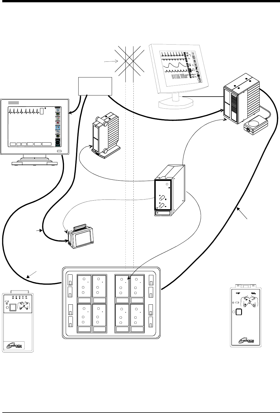
Figure 1-1: Ultraview Digital Telemetry System
Diversity
Antenna
System
Ultraview 1700
receiver module
Digital Telemetry Module Housing
SDLC
90479-A
90478-Q/T/V
E
C
G
VI
ST=0.00
A=3
70
HELP: Acce ss controls that pertain t o ECG
ECG MENU
ALARM
LIMITS SIZE SETUP LEAD
SELECT
CHANNEL
FORMAT
SUSPEND
PROCESSING
UCW bedside or central
remote module
91341/91347
SDLC
NOTE: The UCW bedside connects to
the remote module housing, and the
UCW central connects to the digital te-
lemetry module housing.
Digital Telemetry
Ultraview 1050/1030
Ultraview 1500 or
91343
Digital Telemetry
Multi-parameter Transmitter
ECG Transmitters
housing
shown with flat
panel display
ETHERNET
HUB
10BaseT
Ethernet
Option

Introduction
071-0774-00 Rev. A 1-9
Cleaning
Clean the transmitter after each use. The transmitter does not require any
preventive maintenance other than cleaning.
To clean the transmitter, use only the following agents.
• Mild soap and water solution
• U.S. Pharmacopoeia (USP) green soap
• Sodium hypochlorite solution (1:10 dilution of household bleach in water)
• Phenolic germicidal detergent solutions (1% aqueous solutions)
• Isopropyl alcohol solution (70%)
Assigning a Telemetry Channel
Telemetry transmitters have preassigned channel frequencies. This channel
number is identified on the back of the case and cannot be changed. To receive
this telemetry channel, one of the receivers in the telemetry receiver housing must
be tuned to its assigned frequency.
Tuning a Receiver for a Bedside
The central monitor must be tuned by a qualified service person, but the bedside
monitor may be tuned using the ECG TM SETUP menu. You may use this menu
to tune the receiver module to the pre-assigned channel frequencies on the
telemetry transmitter.
!• Tuning telemetry receiver modules to transmitter channels at
the central monitor must be done by a qualified service person.
• Your central monitor can be configured to remember beds that
are assigned to individual telemetry channels using the Module
Configuration Manager feature. These beds are permanently
assigned until you unassign or reassign them. Refer to the
Module Configuration Manager chapter of the UCN Operations
Manual.
!• The module default is set for North America using UHF band
operation. For alternate band operation, or if operating in
another country, you must select the appropriate frequency
band using the Module Configuration Manager.
To set up the central for ECG (if
bed name not remembered):
1Touch key label that matches
transmitter's frequency
2Select bed/room number for
transmitter channel
To set up the central for ECG
(MPT=OFF) (UCW and 1700):
1Touch MONITOR SETUP
2Touch SCREEN FORMAT
3Select subnet and bed/room
number
4Select ECG and then desired
zone
To tune a receiver module at
bedside:
1Touch ECG
2Touch SETUP
3Touch TM SETUP
4Touch SET TM CHANNEL
5Select the digit to change. Use
the ↑ ↓ keys to select the value
for that digit
6Repeat for all digits as
necessary
7Touch STORE

Ultraview Digital Telemetry
1-10 071-0774-00 Rev. A
Entering Patient Information
The ADMIT/DISCHARGE menu enables you to enter a patient identification (ID)
number, name, height, weight, and body surface area (BSA).
Discharging a Patient
A patient is discharged by first removing the battery from the 91343/91347
Ultraview Digital Telemetry Transmitter. The monitor displays the squelch
waveform followed by the message INTERMITTANT SIGNAL LOSS after a short
delay. An alarm condition is displayed on the monitor because of the signal loss.
The message IS SIGNAL LOSS PERMANENT? appears with keys labeled YES
and NO in the waveform zone. Touch YES to indicate that the signal loss is
permanent. Touch NO to cancel the discharge operation.
The next message displayed is DISCHARGE THE PATIENT?. Touch YES to
continue the discharge process. Touch NO to cancel the discharge operation.
The monitor displays PURGES DATA-ARE YOU SURE? Touch YES to discharge
the patient and erase all patient data. The intermittent signal loss alarm is then
canceled. Touch NO to cancel the discharge operation and cause the message IS
SIGNAL LOSS PERMANENT? to appear in the waveform zone.
!• Admitting a new patient purges data from the previous patient
on that telemetry channel.
WARNING:
• During INTERMITTANT SIGNAL LOSS message activation,
the display of SpO2 and NIBP data is disabled.
To admit a patient:
1Touch MONITOR SETUP
2Touch ADMIT/DISCH
3Select subnet (UCW and 1700
only)
4Select bed/room number for
channel
5Touch ADMIT
6Select YES
7Use keyboard to enter patient
info (UCW and 1700 only)
8Select ID, NAME, HEIGHT,
WEIGHT, or BSA,
UV1050/1500 only)
9Enter data using pop-up keypad
or keyboard ( UV1050/1500
only)
10 Touch ENTER
11 Repeat steps 7 - 10 until all data
has been entered
12 Touch ACCEPT (UCW and
1700 only)
To discharge a patient:
1Remove battery
2Disconnect the transmitter from
the patient
3Select YES to confirm signal
loss permanent
4Select YES to discharge
5Select YES to purge data

Introduction
071-0774-00 Rev. A 1-11
Acknowledging Signal Loss
When a telemetry signal is lost because the transmitter is out of range or the
battery is removed, the receiver initiates a squelch condition indicated by a
triangular waveform that replaces the normal ECG waveform and SQUELCH is
included in the edge print for any strip chart recording. The ECG trace
automatically begins again if the lost signal returns.
After eight seconds of signal loss, the IS SIGNAL LOSS PERMANENT? message
appears. Selecting NO suspends alarm tones. Selecting YES displays the
message DISCHARGE THE PATIENT? Selecting YES again, provides you with
the message PURGES DATA-ARE YOU SURE? Selecting YES a third time,
discharges the patient from the system and purges all data for that patient.
Selecting NO at any point in this sequence returns you to the previous option.
Setting Battery Status Alarms
The telemetry battery alarm tone, and a LOW BATTERY message in the ECG
zone involved, alerts you to a low battery condition in the transmitter. You may
disable the low battery alarm tone, if your bedside or central is configured to
do so.
The factory default setting for low battery alarm is ON.
Controlling Patient-Initiated Recordings
If the Patient Record function is activated (PT RECORD is YES) in the ECG TM
SETUP menu, the patient may initiate a recording by pressing the RECORD
button on the front of the transmitter.
Telemetry Alarm Message Summary
INTERMITTENT SIGNAL LOSS
The intermittent signal loss message indicates that the patient may be out of
antenna range, or the battery is depleted. Return the patient into antenna range.
Check that the battery is functioning properly.
LOW BATTERY
A Low Battery Message indicates that the battery is weak. After this message
appears, the battery has approximately three hours of useful life left (depending
on the type of battery used). Install new battery.
SIGNAL INTERFERENCE
The Signal Interference message indicates, via the displayed triangle squelch
waveform, that an interfering signal has been detected.
PERMANENT SIGNAL LOSS
The Permanent Signal loss message indicates that no RF signal is being
detected.
To control low battery alarms:
1Touch ECG
2Touch SETUP
3Touch TM SETUP
4Select LO BAT ON or OFF
To control transmitter's Patient
Record function:
1Touch ECG
2Touch SETUP
3Touch TM SETUP
4Select PT RECORD YES or NO

Ultraview Digital Telemetry
1-12 071-0774-00 Rev. A
Accessories
Refer to the Spacelabs Medical Supplies Products Catalog for availability of
accessories. Some of the more commonly used accessories are listed below.
Digital Telemetry Accessories
91341/91343/91347 telemetry transmitter pouch 015-0500-00
Belt clip 344-0020-00
Receiver whip antenna (UHF) 117-0040-00
Receiver housing protective cover 200-0180-00
ECG Accessories
DIN standard safety lead wire set, 5 wire 012-0605-00
Adult general purpose electrode 015-0097-01
Holter/stress disposable electrode 392015-001
SpO2 Accessories
Nellcor SpO2 adapter cable 700-0014-00
Nellcor SpO2 sensors Adult/Neonatal (N-25) 690-0006-00
Pediatric (P-20) 690-0007-00
Adult disposable (D-25) 690-0001-00
Finger clip (DS-100A) 690-0003-00
Nasal (R-15) 690-0005-00
Oxiband A/N 690-0004-00
Oxiband pediatric/infant reusable sensor P/I 690-0039-00
NIBP Accessories
ABP adapter cable 700-0015-00
ABP Pouch 015-0501-00
ABP Shoulder Strap 016-0262-00
Cuff assembly, child (13-20 cm) w/ hose 015-0118-01
Cuff assembly, small adult (17-26 cm) w/ hose 015-0067-01
Cuff assembly, adult (24-32 cm) w/ hose 015-0068-02
Cuff assembly, large adult (32-42 cm) w/ hose 016-0077-01
Cuff assembly, extra-large adult (38-50 cm)
w/ hose and cuff support harness 016-0109-01
ABP Report Management System 90121

Introduction
071-0774-00 Rev. A 1-13
ABP Report Management System
Adaptor Cable 012-0097-02
90121 ABP Report Management System
Operations Manual 070-0529-xx
90217 ABP Monitor Operations Manual 070-0137-xx
Ultraview Care Network Operations Manual 070-1001-xx


Contents
2
071-0774-00 Rev. A 2-1
Overview
Digital telemetry ECG monitoring provides continuous monitoring of
electrocardiographic signals in order to detect abnormal cardiac rhythms,
including life-threatening arrhythmias such as asystole, ventricular fibrillation, and
ventricular tachycardia.
Setting Up ECG Monitoring
To set up ECG monitoring, plug each lead wire into the transmitter, connect each
to an electrode, and then attach the leads to the patient. Match the lead wire color
to the color-coded connectors on the top of the transmitter case. Refer to the ECG
chapter in this manual for details regarding electrode application. Telemetry
patients are commonly ambulatory and require optimal skin preparation and lead
application to minimize motion artifact. After the electrodes and lead wires have
been attached, it is important to tape a loop of lead wire close to the electrode to
minimize stress or pulling on the electrode itself. This is called stress-looping.
ECG monitoring begins when the telemetry receiver module detects a signal sent
by a telemetry transmitter. The telemetry transmitter sends a signal as soon as its
battery is installed.
ECG telemetry reception requires the following minimum conditions:
• The telemetry receiver module must be connected to an Ultraview or PCMS
monitor, either directly or through a module housing, with the power ON and a
Spacelabs Medical diversity antenna connected.
• ECG electrodes must be properly attached to the patient; and lead wires
must be properly attached to the transmitter.
• The transmitter battery must be functional.
• The telemetry receiver module must be tuned to the telemetry transmitter's
frequency (channel number).
To initiate ECG monitoring:
1Select a transmitter
2Note its channel number
3Attach lead wires to transmitter
4Attach lead wires to electrodes
5Apply electrodes to patient
6Install a transmitter battery
7Close the transmitter case
Overview . . . . . . . . . . . . . . . . . . . . . . . . . . . . . . . . . . . . . . . . . . . . . . . . . . . . . . 1
Setting Up ECG Monitoring . . . . . . . . . . . . . . . . . . . . . . . . . . . . . . . . . . . . . . . . 1
Display Detail. . . . . . . . . . . . . . . . . . . . . . . . . . . . . . . . . . . . . . . . . . . . . . . . . . . 4
Monitoring Paced ECG Patients . . . . . . . . . . . . . . . . . . . . . . . . . . . . . . . . . . . . 5
Restoring Default Settings . . . . . . . . . . . . . . . . . . . . . . . . . . . . . . . . . . . . . . . . . 6
Changing the Display Resolution. . . . . . . . . . . . . . . . . . . . . . . . . . . . . . . . . . . . 6
Selecting Options for Lead Display . . . . . . . . . . . . . . . . . . . . . . . . . . . . . . . . . . 7
ECG Alarm Message Summary. . . . . . . . . . . . . . . . . . . . . . . . . . . . . . . . . . . . . 9
2ECG

Ultraview Digital Telemetry
2-2 071-0774-00 Rev. A
ECG monitoring in telemetry is identical to hardwired ECG monitoring. Refer to
the ECG, Arrhythmia, and ST Analysis chapters of the UCN Operations Manual
for detailed descriptions of configurations, displays, and controls. A brief overview
of ECG monitoring follows.
Electrodes
For ECG tracing with telemetry, use silver/silver-chloride electrodes or their
equivalent. Always connect all the electrodes required for a particular lead.
Missing electrodes may result in the loss of ECG tracing. Refer to the ECG
chapter in the UCN Operations Manual for information on placing the electrodes.
!• All system connections must be made by Spacelabs Medical
personnel only.
• Leakage currents are not affected by the high level output.
The patient is electrically isolated from the patient monitor by
the RF link.
WARNING:
• Operating television receivers or other CRT displays near
the transmitter (within 2 to 3 feet), or operation of some
pacemaker programmers may suppress the ECG
waveform, preventing QRS detection and rate counting. An
erroneous asystole alarm may result.
• Signals resulting from devices such as Automatic
Implantable Cardiac Defibrillators (AICD) may momentarily
blank the ECG trace rather than display an out-of-range
signal. In such cases, it may not be apparent that the AICD
has signaled and the condition of the patient should be
checked. In all instances of AICD signaling, the bedside or
central will redisplay the ECG waveform within 5 seconds.
WARNING:
• Use only Spacelabs Medical recommended electrodes.
Some electrodes may be subject to large offset potentials
due to polarization. Recovery time after application of
defibrillator pulses may be especially compromised.
Squeeze bulb electrodes, commonly used for diagnostic
ECG recording, may be particularly vulnerable to this
effect.

ECG
071-0774-00 Rev. A 2-3
CAUTION:
• Visually inspect each lead wire for obvious damage and
replace them as needed.
• Only use patient cables and lead wires specified by
Spacelabs Medical. Other cables and lead wires may
degrade performance and may damage the monitor during
defibrillation. Non-Spacelabs Medical cables and lead
wires may also change the required input impedance and
DC offset voltage, affecting monitor performance.
• Do not use stainless steel electrodes.
• Do not allow conductive parts of electrodes and
connectors, including the reference electrode, to contact
other conductive parts, including the ground.
• Poor cable dressing or improper electrode preparation
may cause line isolation monitor transients to resemble
actual cardiac waveforms and inhibit heart rate alarms.
Refer to the ECG chapter of the UCN Operations Manual for
details on proper electrode preparation and application.
Ultraview Digital Telemetry
2-4 071-0774-00 Rev. A
Display Detail
Signal detection is indicated on your monitor when an ECG signal appears next to
the ECG parameter key in the zone assigned to receive the transmitted telemetry
channel. The transmitter's channel number is always identified above the
waveform, to the left of the ECG key.
Figure 2-1: Display Detail
ᕡECG trace for first lead
ᕢTelemetry channel number
ᕣECG key for first lead
ᕤQRS indicator (flashes once per detected beat)
ᕥECG lead designator
ᕦDisplay resolution (monitor or extended)
ᕧPaced operation indication (pacemaker detection is enabled)
ᕨAbnormals per minute alarm limit*
ᕩST segment level for first lead **
µAbnormals in a row alarm limit *
¸ECG rate alarm limits; split screen centrals display a bell symbol when alarms
are enabled; bedsides display the rate alarm limits (120/40)
E
C
G
E
C
G
II MON PACED
ST=0.00
A=3
A/M 10
ROW 4
120
40
VI
ST=0.08
70
CHAN 2241
Split Screen Central
E
C
G
HR=70 A=3 II CHAN 2241
BED 01 DANIELS,R
VI
ᕡᕢ ᕣᕤ
*
ᕥ
ᕨ
ᕩ
µ
ᕦ
*
**
**
E
C
G
BED 01 DANIELS,R
NIBP=120/68(94) 10:20 SpO2=98% 10:20
NIBP=120/68(94) 10:20 SpO2=98% 10:20
18
Full Screen
HR=70
¸
¹
*
Ƹ
ƹ
ƺ
ƻ
ƾƽ
Ƽ
ƽᕧƿ
21
Central/Bedside

ECG
071-0774-00 Rev. A 2-5
¹Abnormals per minute counter *
ƸCurrent heart rate
ƹECG lead designator for second lead
ƺST segment level for second lead**
ƻECG key for second lead
ƼNIBP measurements: systolic/diastolic (mean) at hours:minutes; SpO2
measurement at hours:minutes (91343 only; hh:mm not seen on continuous
SpO2). Depending on the patient monitor’s display size, the title “NIBP” may
not appear.
ƽSpO2 SensorWatch bar: shaded area (waveform index) expands up
proportionally to signal strength; horizontal line is minimum signal level.
Waveform Index (WFI) is used for displaying signal strength in SensorWatch.
ƾLarge size bell indicates ECG alarms enabled.
ƿEqual sign becomes a bell when SpO2 alarms enabled.
Equal sign becomes a bell when NIBP alarms enabled.
* Only appears with the MultiView I or II option in the adult mode with Arrhythmia
detection enabled.
** Only appears in adult mode with the ST segment analysis option.
Monitoring Paced ECG Patients
When monitoring pacemaker patients, use the paced feature to automatically
enhance pacemaker spikes for display and eliminate them from the heart rate
counter. The last YES/NO setting of the paced feature you select is retained as
the default.
If the interval between the pacemaker pulse and the QRS complex is greater than
150 milliseconds, the beat is considered to have originated in the atria and is not
classified as a paced beat.
To prevent pacemaker pulses from being counted as actual beats, specialized
circuitry removes the pacemaker pulses from the ECG signal and replaces them
with pacemaker flags.
!• The optimal leads for monitoring paced patients may vary. In
telemetry monitoring, pacemaker spikes are detected on lead II.
If pacemaker spikes are not detected, change the electrode
position.
To monitor paced patients:
1Touch ECG
2Touch SETUP
3Select PACED YES

Ultraview Digital Telemetry
2-6 071-0774-00 Rev. A
Restoring Default Settings
With the Module Configuration Manager feature, you can restore all default
settings. User-configurable options are listed in the Module Configuration
Manager chapter of the UCN Operations Manual.
Changing the Display Resolution
The MONITOR/EXTENDED key determines the display resolution of the two ECG
traces, whether or not both traces are currently displayed on the monitor.
Table 1: Display Resolution
The factory default setting for display resolution is monitor mode.
WARNING:
• ECG detection circuitry may continue to count the
pacemaker rate during occurrences of cardiac arrest or
some arrhythmias. Do not rely entirely upon ECG rate
alarms. Keep pacemaker patients under close surveillance.
• The system may insert pacemaker flags into the ECG
signal in response to signals that are not pacemaker
pulses. Therefore, if you use a Spacelabs Medical monitor
to observe pacemaker performance, you must take into
account all possible sources of pacemaker flags.
• Use the pacemaker manufacturer's performance analyzer
as the primary means of evaluating pacemaker operation.
!• RESTORE SETTINGS changes the user-configurable options
for all parameters in the module.
Key Display Resolution
Monitor (0.5 – 30 Hz)
Extended (0.05 – 30 Hz)
!• Changing the display resolution does not change the waveform
bandwidth used to analyze the ECG signals for the arrhythmia
and ST segment level.
To restore default settings:
1Touch ECG
2Touch SETUP
3Touch RESTORE SETTINGS
4Select YES
To change the display resolution:
1Touch ECG
2Touch SETUP
3Select MONITOR or
EXTENDED

ECG
071-0774-00 Rev. A 2-7
Selecting Options for Lead Display
One operational mode is available with the 91343 and 91347 multi-lead
transmitters. When all electrodes are connected to the patient, leads I, II, III, AVR,
AVL, AVF, and Vx, where x = 1 to 6, are available. When no chest lead is applied,
leads I, II, III, AVR, AVL, and AVF are available using the remaining connected
electrodes.
Table 2: Lead Display Options
Connected Electrodes (X) 91343/91347
Valid Lead Vectors
RL C LL LA RA
X X X X X V1-6, I, II, III, AVR, AVL,
AVF
XX X X I
XXX X II
X X X X III
X X X X I, II, III, AVR, AVL, AVF
XXXI
XX XII
X X X III
X X X X I, II, III, AVR, AVL, AVF
XXXI
XX X II
X X X III
XX X II
!• Combinations of leads not included above produce invalid lead
vectors. In general, for at least one valid vector, either RL or C
and two limb leads must be connected.
• The RA lead wire must be connected to the transmitter at all
times. This lead wire also serves as the transmitter’s antenna.
• If automatic lead select is enabled in the telemetry receiver, the
loss of a lead wire connection on the patient shall result in the
remaining lead vectors in the above table to be available for
display. If the lead wire that was disconnected is restored, the
two existing lead vectors will remain displayed and will only
change by operator intervention.
To select ECG leads:
1Touch ECG
2Touch LEAD SELECT
3Touch 1ST or 2ND LEAD
4Select the desired lead

Ultraview Digital Telemetry
2-8 071-0774-00 Rev. A
Two Operational Modes
Two operational modes are available with the 91341 dual-lead transmitter:
• the standard mode that offers a choice of one V lead (V1-6), plus lead II; or
• the limb lead mode that offers choices of the leads I, II, III, AVR, AVL, or AVF.
The standard mode is available if the chest lead is applied. The limb lead mode is
available when there is no chest lead applied. Loss of the chest electrode
changes the ECG - Lead Select menu to the limb lead mode if the left arm, left leg,
and right arm electrodes are intact.
Table 3: Two Operational Modes
!• With dual-lead transmitters, both modes work correctly with or
without the right leg electrode attached. However, for optimum
performance, the right leg electrode should always be used.
Connected Electrodes
(X) 91341
Valid Lead Vectors
CLALLRA
X X X X V1-6 and II (standard mode)
X X X III (standard mode)
X X X I (standard mode)
X X total lead failure
(standard mode)
X X X II (standard mode)
X X None (lead failure)
X X None (lead failure)
X None (lead failure)
X None (lead failure)
X None (lead failure)
X None (lead failure)
None (lead failure)
X X III (limb lead mode)
X X I (limb lead mode)
X X II (limb lead mode)
X X X I, II, III, AVR, AVL, AVF
(limb lead mode)
!• With dual-lead transmitters, if one of the leads fails, a lead fault
message will be displayed in the upper left corner of the
waveform zone. If there is no valid lead vector, the message
LEADS OFF is displayed and an alarm tone is generated.

ECG
071-0774-00 Rev. A 2-9
ECG Alarm Message Summary
Refer to the ECG Problem Solving section in the ECG chapter of the UCN
Operations Manual for additional conditions and solutions.
CHECK XX
Displayed in the waveform zone, where XX is the name of the faulted electrode.
The message clears after 60 seconds for V1 – V6 and RL. It is not cleared for limb
lead (RA, LA, LL) faults. If multiple electrodes have faulted, only the highest
priority fault is displayed. The limb leads are highest, followed by RL, and then the
Vx leads.
ABNORMAL/MINUTE ALARM
Displayed whenever the initial abnormal in minute count (A=XX) exceeds the ABN
IN MIN alarm setting. This message is displayed for 10 seconds.
ASYSTOLE
Displayed whenever no beat is detected for 5 seconds. This message is displayed
for 10 seconds or the duration of the alarm. An ASYSTOLE message means it
has been 5 seconds or more since a QRS complex has been detected. Check the
patient. If the patient is stable:
• Check that the lead wires are inserted into the proper receptacle.
• Using the continuity tester, check that there is no damage to the lead wires.
• If the amplitude is poor, check the appropriate lead with a 12-lead ECG.
• Check that the transmitter is more than 3 feet from any television receiver or
CRT display.
COUPLET ALARM
Displayed for 10 seconds whenever a couplet is detected and the ABN IN ROW
alarm limit is ON and is set to two.
ECG ALARMS OFF
Displayed in reverse video whenever ECG alarms are OFF.
ECG ALARMS SUSPENDED
Displayed in reverse video whenever alarms have been suspended by pressing
the TONE RESET/ALM SUSPEND key.
ECG PROCESSING SUSPENDED
Appears whenever ECG and arrhythmia processing have been suspended by
pressing the SUSPEND PROCESSING key and menu. This message is
displayed until processing is resumed.
ECG VOLTAGE TOO LOW
Displayed whenever the ECG signal is below the detection threshold. This
message only applies to the ADULT mode for QRS amplitudes in the range of
160 µV to 200 µV. After 10 seconds in this condition, an alarm tone sounds if ECG
alarms are enabled and alarm tones have not been turned OFF or suspended.
The ECG amplitude may have dropped below the R-wave detector threshold
level. Reposition the electrodes to obtain a QRS amplitude of at least 0.20 mV
(adult) or 0.15 mV (neonate).
To set or adjust ECG alarms:
1Touch ECG
2Touch ALARM LIMITS
3Touch ECG ALARMS
4Select ECG ALARM ON
5Select HI, LO, ABN IN ROW,
and ABN PER MIN
6Use arrow keys to adjust
7Touch ST LIMITS CH1 or ST
LIMITS CH2 to adjust ST
segment alarm limits

Ultraview Digital Telemetry
2-10 071-0774-00 Rev. A
HI RATE ALARM
Displayed during high rate alarms for either 10 seconds or the duration of the
alarm.
IN LEARN
Displayed when the software is in learn mode.
CHAN 1 & 2 LEADS OFF
Displayed when lead failures preclude ECG monitoring in both ECG channels 1
and 2. The message is displayed in the waveform zone for the first ECG channel.
An alarm tone sounds if the module has completed its initial period of learning and
ECG processing has not been suspended.
CHAN 1 LEADS OFF
Displayed when a lead failure occurs on ECG channel 1 when automatic lead
switching is disabled.
CHAN 2 LEADS OFF
Displayed when a lead failure occurs on ECG channel 2. The message is
displayed in the waveform zone for both ECG channels 1 and 2.
LO RATE ALARM
Displayed during low rate alarms for either 10 seconds or the duration of the
alarm.
NEW DOMINANT
Displayed for 1 minute when a switch to a different dominant ECG morphology
occurs.
NOISY SIGNAL
Displayed in ECG channel 1 when the ECG software suspends processing on
either channel because of excessive noise on the ECG signal. After 10 seconds in
this condition, an alarm tone sounds if ECG alarms are enabled and alarm tones
have not been turned OFF or suspended. This message is displayed for the
duration of the noisy signal condition plus approximately three seconds. The
patient may be moving excessively. Secure the lead wires to the patient.
• Check the electrodes for good skin adhesion.
• Check lead wires at the transmitter for contact.
RUN ALARM
Displayed whenever a RUN of three or more beats is detected and the ABN IN
ROW limit is set lower than or equal to the number of beats in the run. This
message is displayed for either 10 seconds or the duration of the alarm.
V FIB
Displayed whenever ventricular fibrillation is detected. This message is displayed
for either 10 seconds or the duration of the alarm.

Contents
3
071-0774-00 Rev. A 3-1
Overview
Pulse oximetry enables you to noninvasively monitor a patient's hemoglobin
oxygen saturation either continuously or episodically. The oximetry sensor
contains two light emitting diodes (LEDs) that transmit specific wavelengths
(approximately 660 and 940 nanometers) of light that are received by a
photodetector.
Oxygen saturated blood absorbs light differently than unsaturated blood. Thus,
the amount of light absorbed by the blood can be used to calculate the ratio of
oxygenated hemoglobin to total hemoglobin in arterial blood. This ratio is
displayed as percent SpO2. Normal values range from 95 to 100%.
WARNING:
• A pulse oximeter should NOT be used as an apnea monitor.
• A pulse oximeter should be considered an early warning
device. If a trend towards patient deoxygenation is
indicated, blood samples should be analyzed by a
laboratory co-oximeter.
!• With the Module Configuration Manager feature, you can define
your own default settings for characteristics such as alarm
limits, alarm priority, and display configuration. Refer to the
Module Configuration Manager chapter in the UCN Operations
Manual for further details.
• Blood oxygen saturation monitoring must be performed in
conjunction with ECG monitoring. The ECG lead wires of the
91343 must be connected to the patient in order to perform
ECG and blood oxygen saturation monitoring.
Overview . . . . . . . . . . . . . . . . . . . . . . . . . . . . . . . . . . . . . . . . . . . . . . . . . . . . . . 1
Setting Up SpO2 Monitoring . . . . . . . . . . . . . . . . . . . . . . . . . . . . . . . . . . . . . . . 2
Ensuring Accurate Monitoring . . . . . . . . . . . . . . . . . . . . . . . . . . . . . . . . . . . . . . 3
Setting or Adjusting Alarm Limits. . . . . . . . . . . . . . . . . . . . . . . . . . . . . . . . . . . . 4
Setting SpO2 Data Averaging Period and Sampling Interval . . . . . . . . . . . . . . 6
Viewing Pulse Rate . . . . . . . . . . . . . . . . . . . . . . . . . . . . . . . . . . . . . . . . . . . . . . 7
SpO2 with Intra-Aortic Balloon Pumps . . . . . . . . . . . . . . . . . . . . . . . . . . . . . . . 7
Using SpO2 with Neonates . . . . . . . . . . . . . . . . . . . . . . . . . . . . . . . . . . . . . . . . 8
SpO2 Alarm Message Summary . . . . . . . . . . . . . . . . . . . . . . . . . . . . . . . . . . . . 8
SpO2 Troubleshooting Guide . . . . . . . . . . . . . . . . . . . . . . . . . . . . . . . . . . . . . 10
3SpO2 (91343 only)

Ultraview Digital Telemetry
3-2 071-0774-00 Rev. A
Setting Up SpO2 Monitoring
The 91343 digital telemetry multi-parameter transmitter uses Spacelabs Medical
sensors as well as those from other manufacturers. Refer to Accessories on page
1-12 for information concerning specific sensors.
All sensors require an adapter cable between the sensor and the transmitter.
Because the adaptor cable is reusable, do not discard it when you have finished
using a disposable oximetry sensor. Disconnect the sensor cable from the adapter
cable before discarding the sensor.
To connect the SpO2 adapter cable to the transmitter, align the cable with the
notch on the front of the transmitter connector, and push the cable straight down
into the transmitter. To remove the cable, press the latch release on the bottom of
the cable, and pull the cable straight out.
Figure 3-1: SpO2 Adapter Cable to Transmitter
To enable SpO2 monitoring in the 91343 digital telemetry multi-parameter
transmitter, choose an averaging interval of 4, 8, or 16, seconds by setting DIP
switches 1 and 2 as explained in Setting SpO2 Data Averaging Period and
Sampling Interval on page 3-6.
CAUTION:
• Use only patient sensors specified by Spacelabs Medical.
Using sensors other than those specified may degrade
performance and damage the transmitter during
defibrillation.
• Check the sensor site frequently. Do not allow the sensor
to remain on one site for a prolonged time, especially when
monitoring neonates. Refer to the sensor manufacturer's
instructions.
• Never attach an SpO2 sensor on a limb being monitored
with a blood pressure cuff or a limb with restricted blood
flow.
• A poorly applied sensor may give inaccurate saturation
values.
• Choose a site with sufficient perfusion to ensure accurate
oximetry values.
CAUTION:
• Never twist the cable.
To set up SpO2 monitoring:
1Open the battery cover and
remove the battery
2Confirm that the DIP switches 1
through 8 are in the correct
setting (Switch 7 must be set to
ON for neonatal use and to OFF
for adult use)
3Reinstall the battery and close
the battery cover
4Connect the SpO2 adapter
cable (P/N 700-0014-00) to the
transmitter
5Attach the sensor to the patient
and connect the sensor cable to
the SpO2 adapter cable
6Initiate ECG monitoring
7Touch ECG
8Touch CHANNEL FORMAT
9Select SpO2 ON
SpO2 (91343 only)
071-0774-00 Rev. A 3-3
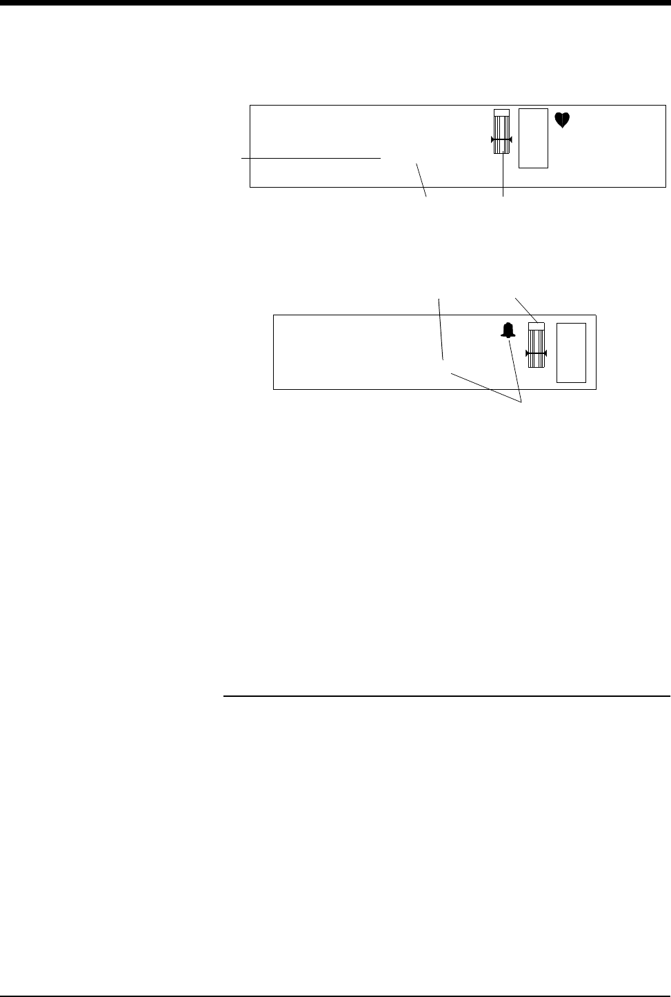
Figure 3-2: Display Zone — Full Screen
Figure 3-3: Display Zone — Split Screen
ᕡCurrent SpO2 value (percent) and episodic time of reading. (Time is not
displayed when using continuous mode of operation.)
ᕢThe bell indicates that alarms are enabled (equal sign turns to a small bell
when SpO2 alarms are enabled).
ᕣSensorWatch bar:
Shaded area (waveform index, WFI) expands up proportionally to signal
strength; horizontal line is minimum signal level.
No shading (lowest waveform index) corresponds to no detected signal
strength or a faulty sensor.
Ensuring Accurate Monitoring
Each sensor requires site specific application procedures, and the following
general points will aid oximetry monitoring success.
• Choose a site that provides proper alignment of the LEDs and receiving
photodetector.
• Reduce light interference when monitoring under bright light by using a light
block over the sensor.
• Select a site that has unrestricted blood flow and can remain as immobile as
possible to reduce or eliminate movement artifact.
• Do not restrict blood flow when securing a sensor with tape.
• Do not select a site near potential electrical interference (e.g., electrical
cords).
• The SensorWatch bar should be above the minimum signal level.
E
C
G
XX YYY PACED
A=XX A/M 10
ROW 5
130
40
78
CHAN 2241
CHECK XX
ECG WAVEFORM ZONE
BED NAME PATIENT NAME
SpO2=98% 10:22
ᕡ
ᕢ ᕣ
E
C
G
HR=XXX A=XX LEAD
ECG WAVEFORM ZONE
SpO2=98% 10:22
347-2 Jane Doe
ᕡ
ᕢ
CHAN 2241
ᕣ

Ultraview Digital Telemetry
3-4 071-0774-00 Rev. A
Setting or Adjusting Alarm Limits
Pulse oximetry alarm limits and delays are based either on factory default limits or
user-defined limits. The factory default settings for alarm limits are 100% for high
and 85% for low. For alarm delays, the factory default settings are 15 seconds for
alarm limit delay and 20 seconds for message alarm delay. Refer to the Alarms
chapter in the UCN Operations Manual for details concerning UCN alarm
operation.
When SpO2 alarms are enabled, a bell symbol will be displayed between the
“SpO2” label and the SpO2 measured saturation value. When any SpO2 alarm is
detected, the displayed parameter value (item 1 in Figure 3-2 and Figure 3-3 on
page 3-3) will blink yellow if the alarm priority is Low or Medium, and will blink red
if the alarm priority is High. This is done independently of any other ECG or NIBP
alarm indications.
When SpO2 alarms are enabled and the SpO2 high limit is exceeded, the SpO2
High=XXX key will blink in the color of the highest priority alarm present. When the
SpO2 low limit is exceeded, the SpO2 Low=XXX key will blink in the color of the
highest priority alarm present. Refer to Directory of Keys - UCW and Ultraview
1700 on page 1-1.
Refer to the Module Configuration Manager chapter of the UCN Operations
Manual for SpO2 parameter tables that list available user settings and factory
defaults for this parameter.
ALM DELAY Key
This key sets the number of seconds the system will wait before it reports that an
alarm limit has been violated. When this feature is OFF, the key label will read
“ALM DELAY OFF”. When it is on, the label will read “ALM DELAY xx”, where “xx”
is the value, in seconds, of the delay.
To set the delay time:
1. Touch ALM DELAY xx (or ALM DELAY OFF).
2. Touch the up and down arrow keys until the value is set as desired. Possible
settings are OFF, 5, 10, 15, 20, 25, or 30 seconds.
!• The following ECG alarm messages take priority over other
ECG and SpO2 alarm messages for display. Other ECG and
SpO2 alarm messages can be adjusted in priority by using the
Module Configuration Manager.
LEADS OFF
NOISY SIGNAL
ECG ALARMS SUSPENDED
!• If you press the down arrow key after the lowest value has been
reached, the following message will appear on the prompt line:
Minimum alarm delay time has been reached.
• If you press the up arrow key after the highest value has been
reached, the following message will appear on the prompt line:
Maximum alarm delay time has been reached.
To set or adjust SpO2 alarms:
1Touch ECG
2Touch ALARM LIMITS
3Touch SPO2 ALARM LIMITS
4Select SpO2 ALARMS ON
5Select HI=, LO=, ALM DELAY,
and MSG ALARM DELAY
6Use arrow keys to adjust

SpO2 (91343 only)
071-0774-00 Rev. A 3-5
MSG ALM DELAY Key
This key sets the number of seconds the system will wait before it issues an alarm
tone after any of the following messages:
•SpO
2 UNAVAILABLE
•SpO
2 FAULTY SENSOR
•SpO
2 SENSOR DISCONNECTED
•SpO
2 SENSOR OFF PATIENT
•SpO
2 INSUFFICIENT SIGNAL
•SpO
2 AMBIENT LIGHT INTF.
•SpO
2 NOISY SIGNAL
When this feature is OFF, the key label will read “MSG ALM DELAY OFF”. When
it is ON, the label will read “MSG ALM DELAY xx” where “xx” is the value, in
seconds, of the delay.
To set the message delay time:
1. Touch MSG ALM DELAY xx (or MSG ALM DELAY OFF).
2. Touch the up and down arrow keys until the value is set as desired. Possible
settings are OFF, 10, 20, 30, 40, 50, or 60 seconds.
!• If you press the down arrow key after the lowest value has been
reached, the following message will appear on the prompt line:
Minimum message alarm delay time has been reached.
• If you press the up arrow key after the highest value has been
reached, the following message will appear on the prompt line:
Maximum message alarm delay time has been reached.
Ultraview Digital Telemetry
3-6 071-0774-00 Rev. A
Setting SpO2 Data Averaging Period and
Sampling Interval
SpO2 data averaging is used to smooth the oximetry saturation value by
averaging the patient input values over 4, 8, or 16 seconds. This selection is made
by setting the DIP switches 1 and 2 beneath the battery compartment in the 91343
digital telemetry multi-parameter transmitter. The default value is 8 seconds.
Refer to Figure 3-4 on page 3-6.
Table 1: DIP Switch 1 and 2 Settings
The current setting of the SpO2 averaging period may be displayed by pressing
the ECG CHANNEL FORMAT key and enabling SpO2.
Figure 3-4: DIP Switch Setting in Battery Compartment
The sampling interval selection enables you to determine how often an SpO2
measurement will be taken. Less frequent SpO2 readings can extend the usable
life of the battery. (Refer to the Ultraview Digital Telemetry Products data sheet,
!• Setting both DIP switches 1 and 2 to ON disables SpO2 data
transmission.
• To enable SpO2, remove the battery, set the selected interval,
and re-install the battery.
• Disabling SpO2 operation in the 91343 transmitter lengthens
battery life.
CAUTION:
• Use care when configuring the DIP switches. Avoid using
pens or pencils to configure the DIP switches since they
may cause contamination. Avoid using sharp cutting
instruments which may cause physical damage.
DIP Switch 1 DIP Switch 2 Effect
OFF OFF 4 seconds averaging enabled
OFF ON 8 seconds averaging enabled (default)
ON OFF 16 seconds averaging enabled
ON ON Disable SpO2 operation
To set SpO2 data averaging
period and sampling interval, set
transmitter DIP switches 1
through 4 to correct
configuration
1 2 3 4
SpO2 averaging
period
SpO2 reading
interval
5 6 7 8
ON
OFF
enable
normal
enabledisable
IABP
disable
NIBP Adult
enable
NIBP
enable
IABP
enable
Neonate
enable
Service use
operation

SpO2 (91343 only)
071-0774-00 Rev. A 3-7
P/N 061-0801-xx, for more information on battery service life.) This selection is
made by setting DIP switches 3 and 4 beneath the battery compartment. The
default setting is in continuous.
Table 2: DIP Switch 3 and 4 Settings
Viewing Pulse Rate
In normal operations, the heart rate for display is obtained directly from the
acquired ECG leads or an alternate rate source. SpO2 can be used as the
alternate source, if it is set for continuous measurement. When it is set for
episodic measurement, SpO2 cannot be used as an alternate rate source.
SpO2 with Intra-Aortic Balloon Pumps
Enabling the intra-aortic balloon pump (IABP) feature informs the SpO2 software
that an IABP is in use. The 91343 must differentiate between true arterial
pulsations and those produced by the IABP. With the IABP feature enabled, the
transmitter excludes the IABP-generated pulsations from the calculation for SpO2.
The IABP feature also may be useful with patients experiencing irregular heart
rhythms. Enabling the IABP feature permits the transmitter to reject irregular
pulses, providing a more accurate SpO2 measurement.
CAUTION:
•No SpO
2 monitoring occurs between episodic sampling
intervals. Clinical practice or medical judgement should be
used in selecting continuous or episodic SpO2 monitoring
mode for each specific patient.
DIP Switch 3 DIP Switch 4 Effect
OFF OFF Continuous sampling (default)
OFF ON 2 minute sampling interval
ON OFF 5 minute sampling interval
ON ON 30 minute sampling interval
CAUTION:
• DIP switch 8 must remain OFF for normal operation.
!• When the IABP feature is enabled, the pulse rate obtained from
SpO2 may not match the heart rate obtained from ECG.
• In cases of excessive patient motion or artifact, the accuracy of
the SpO2 measurement may be compromised when the IABP
feature is enabled.
• When the IABP operation is selected, the SpO2 status key in
the Channel Format menu indicates IABP.
To display heart rate from SpO2
sensor:
1Touch ECG
2Touch SETUP
3Touch RATE SOURCE
4Select SpO2 ON
5Select SpO2 as rate source
To use with balloon pump:
1Set transmitter DIP switch 6 to
ON
To view the current setting of the
IABP DIP switch:
1Touch ECG
2Touch CHANNEL FORMAT
3Select SpO2 ON

Ultraview Digital Telemetry
3-8 071-0774-00 Rev. A
Using SpO2 with Neonates
Enabling neonatal operation, by setting transmitter DIP switch 7, changes the
sensor detection operation in the transmitter, improving the signal quality for
neonatal patients. This switch must be set ON for neonatal use and set OFF for
adult use. When the neonate operation is selected the SpO2 status key in the
Channel Format menu indicates NEO.
SpO2 Alarm Message Summary
SpO2 SENSOR DISCONNECTED
Displayed when the transmitter does not detect either an adapter cable or a
sensor connected to an adapter cable. If the message persists and the adapter
cable is secure, replace the adapter cable. The alarm will stop after approximately
10 seconds. On remote view, there may be no audible alarm on the remote
mainframe before the local alarm stops.
SpO2 FAULTY SENSOR
The 91343 SpO2 processor has detected a defective sensor that will require
replacement. The SensorWatch bar can be used to confirm absence of sensor
output.
SpO2 UNAVAILABLE
Displayed when the LED and/or photodiode have failed. Replace the sensor
and/or SpO2 adapter cable.
SpO2 AMBIENT LIGHT INTF.
Displayed when:
• The sensor is receiving external light interference from a bright light source
near the sensor. Shield the sensor from the external light source. If the
condition persists for more than 30 seconds, ??? will replace the data
display.
• The sensor photodiode and LEDs are misaligned on flexible sensors allowing
light to enter. Realign the sensor photodiode with LEDs.
• If a message appears with finger clip, replace the sensor.
WARNING:
• Error messages indicate a problem or condition that may
affect accurate monitoring values. Do not ignore these
messages. Correct any fault before continuing.
!• When any SpO2 alarm message is displayed, the saturation
value is immediately changed to ??? and an alarm is triggered.
If your module has been configured for an alarm using the
Module Configuration Manager the parameter display will blink
yellow for Low and Medium priority alarms, and will blink red for
High priority alarms. An alarm will begin after the message
alarm delay time has elapsed. (Refer to the Module
Configuration Manager chapter of the UCN Operations
Manual).

SpO2 (91343 only)
071-0774-00 Rev. A 3-9
SpO2 INSUFFICIENT SIGNAL
Displayed when:
• Insufficient signal for proper operation.
• Poor sensor application or site. Correctly re-apply or reposition to a more
perfused site, massage the site, or apply a new sensor.
SpO2 NOISY SIGNAL
Displayed when:
• The sensor signal is disturbed by motion or other interference. Eliminate
sensor movement. The message disappears when a value is obtained.
• The sensor is placed adjacent to power cords or other electrically noisy
devices. Move the noisy device or move the sensor to another site.
SpO2 SENSOR OFF PATIENT
Displayed when:
• The transmitter is unable to detect a valid sensor input signal. Check the
patient for proper sensor placement.This alarm is only available when the
SpO2 sensor is a reusable, finger-clip type.
• Tissue between the LED and photodiode is too transmissive. If sensor
placement seems correct and the message persists, try a sensor site with a
thicker tissue bed.
!• This message is not available with disposable SpO2 sensors or
non-clip type sensors.
!• Adapter cables and sensors are ordered separately through the
Spacelabs Medical Supplies Products Catalog.

3-10 071-0774-00 Rev. A
SpO2 Troubleshooting Guide
Clinical Situation Possible Cause Solution
No SpO2 label is
displayed
■SpO2 is not enabled at the 91343 ■ Be sure transmitter DIP switch 1 and 2
are set correctly
■SpO2 is not enabled at the 90478
receiver
■ Be sure transmitter DIP switch 8 is
OFF
SpO2 value displays ??? ■Sensor not connected to patient ■Re-attach sensor
■Adapter cable not connected to module
properly
■Correctly connect the adapter cable
■Sensor not connected to adapter cable ■Correctly connect the sensor
■Excessive patient motion ■Urge patient to remain still while
reading is in progress
■Transmitter is in the initialization phase
(the first 15 seconds after sensor
application)
■Wait until initialization is complete
■Low battery indicator constantly
illuminated
■Call qualified service person
Insufficient signal or
noisy signal
■Sensor placement not optimum ■Move sensor to a site which has better
perfusion
■Align LED with sensor photodetector
■Sensor placed below blood pressure
cuff
■Move sensor to an alternate limb
Intermittent or complete
failure to operate
■Depleted battery ■Replace battery
■Low battery light constantly illuminated ■Call qualified service person
Factors that cause
significant variances in
sensor accuracy
■Presence of dysfunctional hemoglobins
(COHb, MetHb)
■Follow hospital procedure for
determining oxygenation in these
patients
■Presence of intravascular dyes
(indocyamine green, methylene blue)
depending on their concentration in the
blood stream
■Follow hospital procedure for
determining oxygenation in these
patients
■High ambient light level ■Reduce light levels near patient; wrap
sensor with light blocking material
■Electrosurgical interference ■Ultraview digital telemetry is contra-
indicated for electrosurgical use
■Patient is significantly anemic (Hb less
than 5 gm/dl) or patient has received
large amounts of IV solutions
■Follow hospital procedure for
determining oxygenation in these
patients

071-0774-00 Rev. A 3-11
SpO2 Troubleshooting Guide (continued)
Clinical Situation Possible Cause Solution
No SpO2 alarms are
displayed
■ECG “Leads Off” condition exists
■Higher priority alarm condition is
present
■Re-attach ECG lead wires to patient and
resume ECG monitoring to clear
pending ECG alarms
■Clear current alarm condition and/or
reprioritize SpO2 alarms of interest in the
Module Configuration Manager
■When SpO2 alarms are set ON, all SpO2
alarm conditions will cause the
parameter value (or ???) to blink
according to the alarm priority set by
using the Module Configuration Manager


Contents
4
071-0774-00 Rev. A 4-1
Overview
The 91343 digital telemetry multi-parameter transmitter sends NIBP patient data,
acquired by the 90217 ambulatory blood pressure (ABP) monitor, to the 90478
digital telemetry receiver. The 90478 displays the patient’s episodic NIBP data
and trigger alarms based on thresholds set at the patient monitor.
The 90217 ABP monitor is a small, lightweight, battery-powered unit designed to
take blood pressure measurements. Refer to the 90217 Operations Manual
(070-0137-xx) for more detailed information on this product, its initialization by a
direct PC interface (90121 ABP Report Management System Operations Manual
070-0529-xx), Patient Preparation, and Event Codes.
NIBP uses oscillometric monitoring to measure systolic (S), diastolic (D), and
mean (M) arterial blood pressures. The pressure readings are sent from the
90217 ABP monitor to the 91343 transmitter by a connecting cable. The 91343
transmitter then includes the NIBP readings in the communications to the 90478
receiver using the radio frequency data link. Received NIBP measurements are
checked to eliminate the possibility of erroneous readings and valid
measurements are displayed on the patient monitor and stored in the patient
monitor for trending. The Ultraview monitor displays valid measurements and the
time the measurement was acquired. The most recent reading is displayed by the
Ultraview monitor. The most recent 120 readings are stored and may be displayed
by the monitor.
90217 ABP Monitor
Overview . . . . . . . . . . . . . . . . . . . . . . . . . . . . . . . . . . . . . . . . . . . . . . . . . . . . . . 1
Setting Up NIBP Monitoring. . . . . . . . . . . . . . . . . . . . . . . . . . . . . . . . . . . . . . . . 2
Setting Up the ABP Monitor. . . . . . . . . . . . . . . . . . . . . . . . . . . . . . . . . . . . . . . . 3
Setting or Adjusting Alarm Limits. . . . . . . . . . . . . . . . . . . . . . . . . . . . . . . . . . . . 7
Displaying New or Previous Readings. . . . . . . . . . . . . . . . . . . . . . . . . . . . . . . . 8
NIBP Alarm Message Summary . . . . . . . . . . . . . . . . . . . . . . . . . . . . . . . . . . . . 9
NIBP Troubleshooting Guide . . . . . . . . . . . . . . . . . . . . . . . . . . . . . . . . . . . . . . 11
4NIBP (91343 only)

Ultraview Digital Telemetry
4-2 071-0774-00 Rev. A
Setting Up NIBP Monitoring
Proper cuff selection and application is critical in ensuring the accuracy of NIBP
readings. To ensure proper cuff selection, first measure the circumference of the
limb at its midpoint. Match the limb measurement to the range of appropriate
circumferences (in centimeters) specified on each cuff. If the cuff bladder is too
wide for the patient, the reading will be falsely lowered; if it is too narrow, the
reading will be falsely elevated. Undersizing the cuff results in the greatest chance
of error, so a variety of cuff sizes should be available to accommodate your full
patient population.
Apply the cuff snugly. When the cuff is properly applied to an adult, you should be
able to insert one finger between the cuff and the arm. If you can insert two
fingers, the cuff is too loose, which may result in falsely elevated readings. Ensure
that the hose is not kinked when the cuff is applied.
During blood pressure measurement, the inflated cuff reduces blood flow to the
limb to which it is applied. Do not apply a cuff to a limb that has restricted blood
flow. Check the patient periodically.
!• The 90217 ABP Monitor is intended for use with adult patients
only and, when used with the 91343 Digital Telemetry System,
must also involve ECG monitoring.
• The ECG lead wires of the 91343 must be connected to the
patient in order to perform ECG and NIBP monitoring.
• The 90217 ABP, when used with the 91343 Digital Telemetry
system, purges its measurements as they are successfully sent.
This operation differs from when the 90217 ABP is used in a
stand-alone manner and stores a maximum of 240 NIBP
readings and event codes.
• NIBP readings which are not successfully transmitted by the
90217 to the 90478 within twenty-four hours of their
measurement are unavailable for patient monitor display or
trending.
!• Do not apply a blood pressure cuff to a limb being monitored
with a pulse oximetry sensor, because SpO2 is affected during
NIBP readings. Avoid applying a cuff to a limb that has an
intravenous line in place. Do not apply a cuff to a limb that has
restricted blood flow.
• Use only single hose cuffs to ensure proper operation.
Spacelabs Medical’s hoses are non-conductive with respect to
defibrillator discharge effects.
To set up NIBP monitoring:
1Configure 91343 DIP switch 5
to ON (refer to Figure 4-4 on
page 4-7)
2Initialize 90217 with 90121
ABP report management
system using the ABP Remote
Management System adapter
cable (P/N 700-0015-00)
3Apply appropriate cuff to
patient
4Attach cuff to 90217 monitor
5Connect NIBP adapter cable
(012-0588-00) between 90217
and 91343
6Touch ECG
7Touch CHANNEL FORMAT
8Select NIBP ON

NIBP (91343 only)
071-0774-00 Rev. A 4-3
Patient Factors Affecting Readings
Excess patient movement, speech, or muscle contractions as a result of severe
pain or shivering can interfere with automated NIBP readings. Ensure that the
patient is quiet and not moving during NIBP readings just as you would manual
readings. The patient must avoid applying external pressure to the cuff during
readings. Institute measures to minimize shivering and alleviate pain.
Some arrhythmias may cause beat-to-beat pressure fluctuations that can make
obtaining NIBP readings more difficult. If it becomes difficult to obtain readings in
the presence of arrhythmia, pressure should be temporarily verified using another
method (i.e., ausculatory, oscillometric, Doppler). Pressure also varies cyclically
with normal respiration. With deep respirations or in certain patients this effect
may be enhanced, increasing reading variability.
For patients in shock, indirect methods of measuring pressure (auscultatory,
oscillometric, Doppler) may not be reliable because of peripheral vascular
changes. These changes include peripheral vasoconstriction and diminished
peripheral circulation resulting from shunting of blood to central organs. In some
cases, peripheral pulses or Korotkoff sounds may be diminished or disappear in
spite of adequate blood pressure. In such cases, measuring a cuff pressure may
be impossible or give misleading results. Direct blood pressure measurements
(invasive) should be considered in patients with signs of shock or any patient who
rapidly becomes unstable for unknown reasons.
Setting Up the ABP Monitor
The 90217 ABP must be initialized prior to the monitoring of each patient.
Initialization is accomplished using the 90121 ABP report management system.
(Refer to the Setting Up the ABP Monitor chapter in the 90217 Operations
Manual, 070-0137-xx.)
After the monitor has been initialized, prepare the patient for monitoring as
follows:
1. Turn on the monitor and wait for the monitor to perform self-tests. When the
LCD displays the current time, the monitor is ready for operation.
2. Strap the monitor to the patient on the hip opposite the side on which the cuff
is worn. Secure the monitor using the patient's own belt or the ABP pouch
strapped over the opposite shoulder. When using the shoulder strap, use the
belt supplied with the monitor, or the patient’s belt, to provide additional
security.
3. To select the proper cuff, measure the circumference of the limb at the point
where the cuff is to be applied. Match the limb measurement to the range of
appropriate circumferences (in centimeters) specified on each cuff (refer to
Table 1 on page 4-4).
CAUTION:
• Failure to initialize the 90217 as specified may result in the
display and storage of measurements that are incorrect or
that were acquired from a prior patient. The operator must
initialize the 90217 before each patient use.

Ultraview Digital Telemetry
4-4 071-0774-00 Rev. A
Table 1: Cuff Size by Limb Circumference
4. Position the cuff so that the center of the inflatable bladder is directly over the
brachial artery. The center of the bladder location is marked on the outside of
the cuff. Once the proper position is determined, the cuff must be tightened to
ensure that it is equally snug at the top and bottom edges and that it is not
kinked. This is especially important on larger arms. Insert a finger between the
cuff and the limb to ensure it is not too tight. It may be necessary to wrap the
cuff with its tail at an angle to achieve uniform tightness. If the cuff is not
equally snug at the top and bottom edges, the number of readings available
will be limited and the monitor may indicate that the cuff is improperly applied.
5. Once the cuff is applied, the arm should be relaxed at the patient's side. To
avoid reading errors due to hydrostatic pressure differences, the level of the
cuff on the arm should be near the level of the heart.
Cuff Size Limb Circumference
Pediatric 13 to 20 cm
Small adult 17 to 26 cm
Average adult 24 to 32 cm
Large adult 32 to 42 cm
Extra-large adult 38 to 50 cm
!• Use only Spacelabs Medical cuffs with this monitor. Using other
manufacturer’s cuffs may result in inaccurate readings, even if
the manufacturer’s recommended size is observed.
• If the cuff is too small, pressure readings may be falsely high; a
cuff that is too large produces a falsely low reading. The bladder
can be positioned in the cuff for either the left or right arm.
CAUTION:
• Avoid compression or restriction of pressure in the NIBP
patient connector tubes. Check that operation of the
equipment does not result in prolonged impairment of
circulation.
• Do not apply cuff to areas of breached or injured skin.
• Cuff hose connections use luer fittings. Be careful not to
connect the ABP monitor into an intravenous fluid line
when working close to them.
• This product contains natural latex rubber components to
which some people may be allergic. These components
include the bladder and the first four inches of tubing
extending from the cuff.
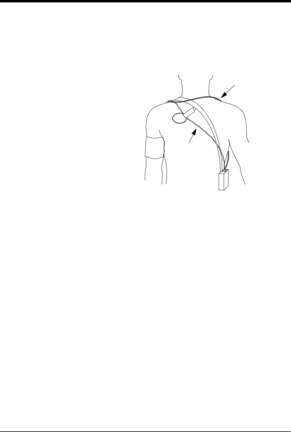
NIBP (91343 only)
071-0774-00 Rev. A 4-5
6. Lead the hose up the arm with the cuff and place it across the back of the
patient. Drape the hose so it does not cause the patient discomfort and is not
pinched shut by too tight a radius. Figure 4-1 shows the most common
positions for the cuff hose.
Figure 4-1: Common Cuff Hose Positions
7. Connect the hose to the monitor.
8. To verify proper monitor operation, take one or more blood pressure readings.
Push the START/STOP key to begin a measurement.
9. The 91343 transmitter must be configured for use with the 90217 ABP monitor
by opening the battery compartment door, removing the battery, and setting
DIP switches 5 ON and 8 OFF. Refer to Figure 4-4 on page 4-7.
10. The 90478 receiver must be configured for operation with the 91343
transmitter and attached 90217 ABP. Touch the monitor ECG key to display
the main menu. Touch CHANNEL FORMAT, then NIBP ON. The monitor will
display the NIBP measurement in a numeric format in the display zone. The
values of the measurement are displayed as ??? until a valid NIBP
measurement has been taken.
alternative #1
alternative #2
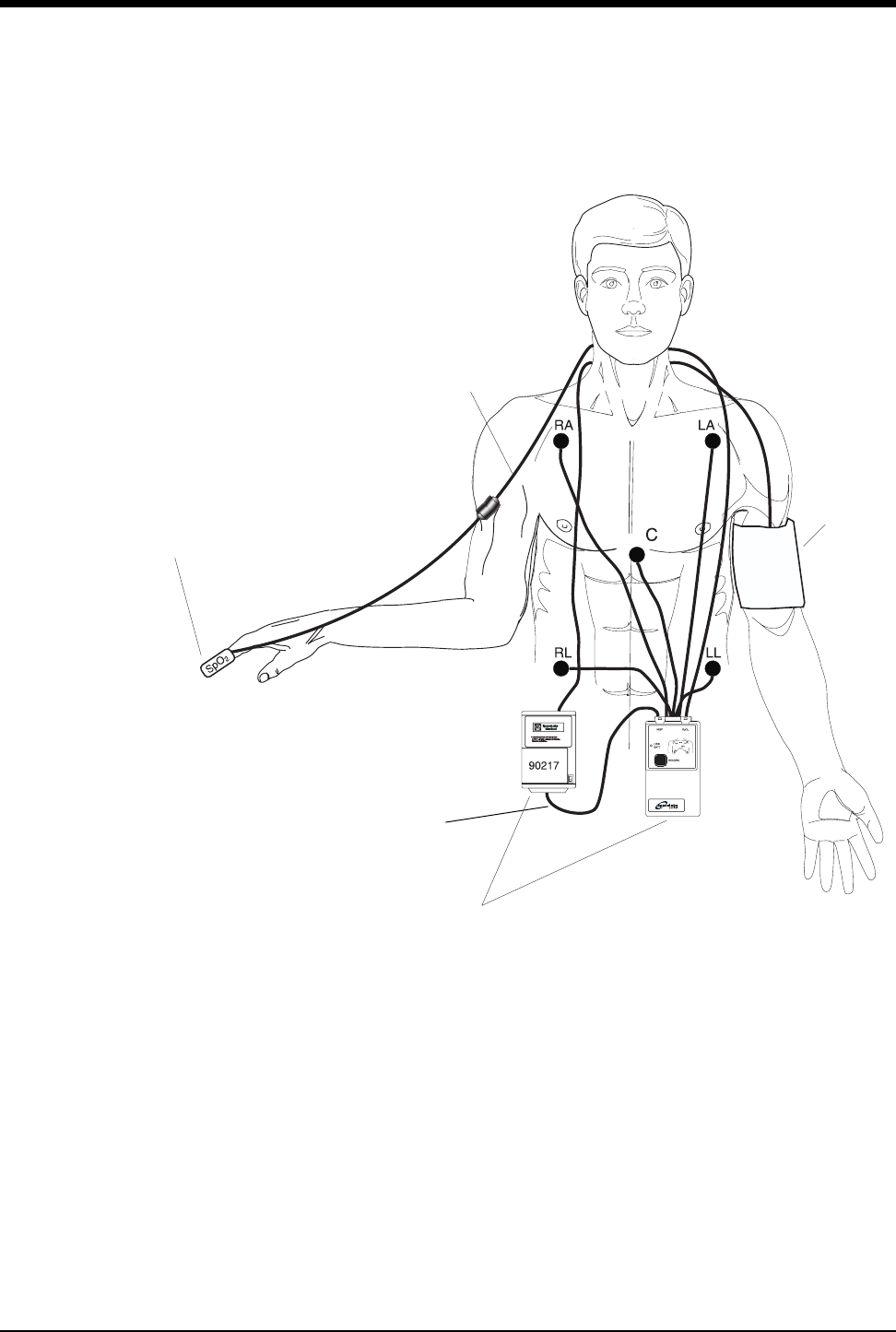
Ultraview Digital Telemetry
4-6 071-0774-00 Rev. A
11. Interconnect the adapter cable between the communications port on the
90217 and the NIBP port on the 91343 as shown in Figure 4-2.
Figure 4-2: Transmitter ECG, SpO2, and ABP Monitor Connections
Figure 4-3 and Figure 4-4 on page 4-7 illustrate typical NIBP displays. You can
view NIBP readings from any Ultraview bedside or central monitor on a network.
NIBP displays on a split screen central monitor appear in a format slightly different
from that of bedside or full screen central monitors. Depending on the patient
monitor’s display size, the title “NIBP” may not appear.
SpO2 sensor
NIBP adapter cable
NIBP cuff
SpO2
adapter cable
90217 & 91343 mount in
pouches to patient’s belt.
91343
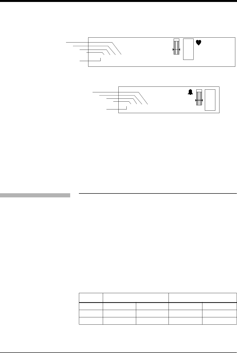
NIBP (91343 only)
071-0774-00 Rev. A 4-7
Figure 4-3: Display Zone — Full Screen
Figure 4-4: Display Zone — Split Screen
ᕡLast systolic reading
ᕢLast diastolic reading
ᕣLast mean reading
ᕤHour and minutes of last reading
ᕥEqual sign becomes bell symbol when NIBP alarms are enabled
Setting or Adjusting Alarm Limits
You can define pressure alarm limits for systolic, diastolic, and mean values. The
default setting for alarms is OFF. Refer to the Alarms chapter in the UCN
Operations Manual for Ultraview system alarm functions.
When any NIBP alarm is detected, the displayed parameter value (refer to Figure
4-3 and Figure 4-4) will blink yellow if the alarm priority is Low or Medium, and will
blink red if the alarm priority is High. This is done independently of any other ECG
or SpO2 alarm indications.
When NIBP alarms are enabled and any of Systolic, Diastolic or Mean is
exceeded (high or low), the corresponding SYS=XXX, DIA=XXX or MEAN=XXX
alarm key will blink in the color of the highest priority alarm present. More than one
alarm condition may be simultaneously present causing multiple alarm keys to
blink. Refer to the Directory of Keys - UCW and Ultraview 1700 on page 1-1.
The alarm limits defaults are below:
Table 2: Alarm Limits
High Low
Systolic 180 mmHg (24.0 kPa) 100 mmHg (13.3 kPa)
Diastolic 120 mmHg (16.0 kPa) 60 mmHg (8.0 kPa)
Mean 130 mmHg (17.3 kPa) 80 mmHg (12.0 kPa)
E
C
G
XX YYY PACED
A=XX A/M 10
ROW 5
130
40
78
CHAN xxxx
ECG WAVEFORM ZONE
BED NAME PATIENT NAME
NIBP=120/68(94) hh:mm SpO2=98% hh:mm
ᕣ
ᕤ
ᕡ
ᕢ
ᕥ
E
C
G
HR=XXX A=XX LEAD
ECG WAVEFORM ZONE
NIBP=120/68(94) hh:mm SpO2=98% hh:mm
CHAN xxxx
BED NAME PATIENT NAME
ᕣ
ᕤ
ᕢ
ᕡ
ᕥ
To set or adjust NIBP alarms:
1Touch ECG
2Touch ALARM LIMITS
3Touch NIBP ALARM LIMITS
4Select NIBP ALM ON
5Select SYS, DIA, or MEAN
6Select HI= or LO=
7Use arrow keys to adjust

Ultraview Digital Telemetry
4-8 071-0774-00 Rev. A
Refer to the Module Configuration Manager chapter in the UCN Operations
Manual for NIBP parameter tables that list available user settings and factory
defaults for this parameter.
Displaying New or Previous Readings
The current (or latest) NIBP reading taken may be displayed when the NIBP
parameter is enabled and the 90217 ABP monitor is correctly setup. The current
reading is displayed just below the isoelectric line showing systolic, diastolic, and
mean values with the time of the reading. The displayed values are replaced by
??? when no valid values have been acquired from the 90217.
The previous NIBP readings may be displayed using the Tabular Trend or
Graphic Trend monitor functions. The parameter trend information is collected
from the module on a minute-by-minute basis and stored in system memory for
retrieval. The collected NIBP trend readings may be displayed in the same
manner as any other monitored parameter. Refer to the Trends chapter in the
UCN Operations Manual for details.
!• The following ECG alarm messages take priority over other
ECG and NIBP alarm messages for display. Other ECG and
NIBP alarm messages can be adjusted in priority by using the
Module Configuration Manager.
LEADS OFF
NOISY SIGNAL
ECG ALARMS SUSPENDED
To display the current reading:
1Touch ECG
2Touch CHANNEL FORMAT
3Select NIBP ON
To display previous readings in
tabular format (1030/1050):
1Touch SPECIAL FUNCTIONS.
2Select LOCAL TRENDS or
REMOTE TRENDS.
3Select subnet and bed number.
4Touch TABULAR TRENDS.
5Select TIME INTERVAL or
ARROWS to adjust the time
interval and period.
(UCW and 1700):
1Touch SPECIAL FUNCTIONS.
2Touch TABULAR TRENDS.
3Select LOCAL BED or
REMOTE BED.
4Select bed number.
5Select TIME INTERVAL or
ARROWS to adjust the time
interval and period.
To display previous readings in
graphic format (1030/1050):
1Touch SPECIAL FUNCTIONS.
2Touch LOCAL TRENDS or
REMOTE TRENDS.
3Select bed number.
4Touch GRAPHIC TRENDS.
5Touch TOP GRAPH of
BOTTOM GRAPH.
6Touch desired parameter to
graph.
(UCW and 1700):
1Touch SPECIAL FUNCTIONS.
2Touch GRAPHIC TRENDS.
3Select LOCAL BED or
REMOTE BED.
4Select bed number.
5Touch desired parameter to
graph.

NIBP (91343 only)
071-0774-00 Rev. A 4-9
NIBP Alarm Message Summary
The 90217 ABP monitor provides an extensive set of result codes that indicate the
status of the monitor and the potential causes of an inability to take a valid
reading.
When any alarm message is displayed, the NIBP parameter value is immediately
changed to ??? and an alarm is triggered. If your module has been configured for
an alarm using the Module Configuration Manager, the parameter display will
blink yellow for Low and Medium priority alarms, and will blink red for High priority
alarms. The alarm condition will persist until a new NIBP reading is taken. (Refer
to the Module Configuration Manager chapter of the UCN Operations Manual).
The following messages are displayed on the UCN monitor to provide ABP status
information to the caregiver. These messages summarize the 90217 event codes.
Some of these messages include an event code in parentheses to provide more
detailed analysis of the event. A complete list of the event codes can be found in
the 90217 ABP Monitor Operations Manual (070-0137-xx).
NIBP UNAVAILABLE (xx)
Displayed when the 90217 ABP monitor has detected an internal condition,
defined by the code (xx). Typically, this indicates a hardware or software failure
that requires that the transmitter be removed from service.
NIBP READING FAILURE (xx)
Displayed when the ABP monitor was unable to make a reading. The code (xx)
defines the cause of failure.
NIBP AIR LEAK
Displayed when an air leak has been detected in the pneumatic system,
preventing a reading from being taken.
Tabular Trends Display
Bed: ICU1 Patient: John Smith Date: 26 FEB 2001
Time 11:32 11:33 11:34 11:35 11:36 11:37 11:38 11:39
HR (ECG) b/min 60 60 59 60 61 60 59 60
ABN b.min 00000 00 0
SpO2% 9697979697 9696 96
SpO2 PRb/min 7070707070 7070 70
SpO2 (WFI) 363 364 362 365 367 285 300 340
NIBP/s Time 11:32 11:37
mmHg 100 102
NIBP/d Time 11:32 11:37
mmHg 72 70
NIBP/m Time 11:32 11:37
mmHg 80 79

Ultraview Digital Telemetry
4-10 071-0774-00 Rev. A
NIBP LOOSE OR NO CUFF
Displayed when the cuff was able to be inflated in a manner indicating that it was
not attached to the patient correctly.
NIBP PATIENT CANCELLED
Displayed when the patient has pressed the START/STOP button on the 90217,
halting a reading in progress.
NIBP LOW BATTERY
Displayed when the primary (3xAA) battery voltage is low. Replace with fresh
batteries.
NIBP KINKED HOSE
Displayed when the pressure value increased too rapidly indicating a kinked hose
or other restriction.
NIBP EVENT CODE (xx)
Displayed when the event code returned from the 90217 monitor is not defined
into one of the other messages.

071-0774-00 Rev. A 4-11
NIBP Troubleshooting Guide
Clinical Situation Possible Cause Solution
No NIBP displays ■Adapter cable not inserted correctly ■Remove and re-insert adapter cable
■NIBP not enabled on 91343 or 90478 ■Enable NIBP function by setting transmitter
DIP switch 5 ON and setting DIP switch 8
OFF
■90217 ABP not properly initialized ■Reinitialize 90217 ABP using 90121
■91343 Low battery indicator constantly
illuminated
■Call qualified service person
No NIBP readings can
be obtained
■Incorrect or inoperative cuff in use ■Replace with cuff known to be operative
■Tubing is kinked ■Locate kink and straighten tubing
■Some arrhythmias (e.g., atrial
fibrillation and frequent ventricular
ectopy) may cause a single or repeated
failure to obtain a reading (may be due
to true beat-to-beat variations in
pressure)
■Document arrhythmia if present, verify
pressure with another method, then follow
hospital procedure for care of this type of
patient
■Excessive patient motion or muscle
contractions associated with shivering
or severe pain
■Ensure that patient is quiet with minimal
movement during NIBP readings; minimize
patient’s shivering
■Blood pressure outside of
measurement range
■Verify extremely high or low pressure with
another method
Intermittent or
complete failure to
operate
■90217 ABP error ■Remove 90217 ABP from service; record
event code; and call qualified service
person
Apparent incorrect
value
■Wrong size cuff for patient ■Measure patient’s limbs at the midpoint;
match limb measurement to range specified
on cuff (undersizing the cuff results in the
greatest degree of error)
■Cuff is damaged ■Replace with good cuff
■Excessive patient motion, shivering or
severe pain
■Ensure patient is quiet with minimal
movement during NIBP readings; minimize
patient’s shivering
■False high readings may be the result
of venous congestion caused by
frequent readings
■Reduce frequency of readings
■Cuff too loose or positioned incorrectly ■Tighten cuff or reposition appropriately

4-12 071-0774-00 Rev. A
NIBP Troubleshooting Guide (continued)
Clinical Situation Possible Cause Solution
90217 ABP Display is
incorrect
■Data not retained ■Replace backup battery
■Low or no power ■Check the batteries for a full charge; if
needed, replace or recharge the batteries
■May be one of the following: time-out,
no reading due to air leak in the
system, improper cuff size, cuff size not
properly attached to the 90217 ABP
■Isolate cause and correct
No NIBP alarms are
displayed
■ECG “Leads Off” condition exists
■Higher priority alarm condition is
present
■Re-attach ECG lead wires to the patient
and resume ECG monitoring to clear
pending ECG alarms
■Clear current alarm condition and/or
re-prioritize NIBP alarms of interest in the
Module Configuration Manager
■When NIBP alarms are set ON, all NIBP
alarm conditions will cause the parameter
value (or ???) to blink according to the
alarm priority set by using the Module
Configuration Manager
Variable readings occur ■Some arrhythmias may cause beat-to-
beat pressure and NIBP readings
■Document arrhythmia if present, verify
pressure using another method, then
follow hospital procedure for care of this
type of patient
■Larger than normal influence of
respiratory phases on blood pressure
(inspiratory fall in blood pressure;
expiratory rise)
■NIBP software usually compensates for
normal variation
No NIBP readings or
questionable values in
the presence of shock
■Peripheral vascular changes
experienced during shock may reduce
the reliability of blood pressure
readings obtained with any indirect
method; peripheral pulses may be
diminished or absent
■Consider invasive pressure
measurements in patients with symptoms
of shock or in any patient who rapidly
becomes unstable for unknown reasons
90217 displays “LLL”
and alarm sounds
■Low main battery condition ■Turn off and replace batteries within 60
seconds after removal to continue
monitoring.
Cuff too tight ■Cuff placed on patient too tightly ■Reposition the cuff
■Air pump staying on too long ■Return unit to Spacelabs Medical for
service
Cuff too loose ■Cuff placed on patient too loosely ■Reposition the cuff
■Air pump not staying on long enough ■Return unit to Spacelabs Medical for
service

Contents
5
071-0774-00 Rev. A 5-1
Alarm Message Summary
Most of the alarm message priorities in the Ultraview Digital Telemetry system are
user-preset choices in the Module Configuration Manager menus (refer to the
Module Configuration Manager chapter of the UCN Operations Manual). These
priorities are shown in the TONE column and allow selection of one out of four
possible levels.
•HIGH
•MEDIUM
•LOW
•NONE
There are a few priority choices of alarm messages that are factory-preset and
cannot be changed. When one of these choices is selected, a message displays
indicating, “This setting cannot be changed.”
The remaining alarms (and alarm messages) that can be prioritized by the user
are observed according to these preset priorities when multiple alarms are
concurrently active. The alarm with the HIGHER priority is activated and its
associated alarm message is displayed. The alarm message(s) with a LOWER
priority setting(s) in MCM is displayed when and only when the alarm message
with the HIGHER priority is cleared.
Prior to any clinical monitoring session, the user is advised to configure these
alarm priority settings in MCM and select those options that are best suited to the
desired level of patient monitoring surveillance.
Unless otherwise specified in their description, the following messages are left on
the top line (full screen monitors, medium font) or second line (split screen
monitors, small font) of the waveform zone. They are displayed for the duration of
the condition that caused the message or for the period specified in their
description unless replaced by a higher priority message. The conditions under
which these messages can be displayed are outlined below. During alarms, alarm
messages flash unless alarms are suspended.
Alarm Message Summary . . . . . . . . . . . . . . . . . . . . . . . . . . . . . . . . . . . . . . . . . 1
ECG Alarm Messages . . . . . . . . . . . . . . . . . . . . . . . . . . . . . . . . . . . . . . . . . . . . 2
SpO2 Alarm Messages . . . . . . . . . . . . . . . . . . . . . . . . . . . . . . . . . . . . . . . . . . . 3
NIBP Alarm Messages. . . . . . . . . . . . . . . . . . . . . . . . . . . . . . . . . . . . . . . . . . . . 4
Telemetry Alarm Messages . . . . . . . . . . . . . . . . . . . . . . . . . . . . . . . . . . . . . . . . 5
5Alarms

Ultraview Digital Telemetry
5-2 071-0774-00 Rev. A
ECG Alarm Messages
The following messages apply when either the 91341, 91343, or 91347 is in use.
CHECK XX
Displayed in the waveform zone, where XX is the name of the faulted electrode.
The message clears after 60 seconds for V1 – V6 and RL. It is not cleared for limb
lead (RA, LA, LL) faults. If multiple electrodes have faulted, only the highest
priority fault is displayed. The limb leads are highest, followed by RL, followed by
the Vx leads.
ABNORMAL/MINUTE ALARM
Displayed whenever the abnormal in minute count (A=XX) initially exceeds the
ABN IN MIN alarm setting. This message is displayed for 10 seconds.
ASYSTOLE
Displayed whenever no beat is detected for 5 seconds. This message is displayed
for the greater of 10 seconds or the duration of the alarm.
COUPLET ALARM
Displayed whenever a couplet is detected and the ABN IN ROW alarm limit is ON
and set to 2. This message is displayed for 10 seconds.
ECG ALARMS OFF
Displayed in reverse video whenever ECG alarms are OFF.
ECG ALARMS SUSPENDED
Displayed in reverse video whenever alarms have been suspended with the
monitor’s TONE RESET/ALM SUSPEND hard key.
ECG PROCESSING SUSPENDED
Appears whenever ECG and arrhythmia processing have been suspended with
the SUSPEND PROCESSING key and menu. This message is displayed until
processing is resumed.
ECG VOLTAGE TOO LOW
Displayed whenever the ECG signal is below the detection threshold. This
message only applies to ADULT mode for QRS amplitudes in the range of 160 µV
to 200 µV. After 10 seconds in this condition, an alarm tone sounds if ECG alarms
are enabled and alarm tones have not been turned OFF or suspended.
HI RATE ALARM
Displayed during high rate alarms for the greater of 10 seconds or for the duration
of the alarm.
IN LEARN
Displayed when the module is in learning mode.
CHAN 1 & 2 LEADS OFF
Displayed when lead failures preclude ECG monitoring in both ECG channels 1
and 2. The message in displayed in the waveform zone for the first ECG channel.
An alarm tone sounds if the module has completed its initial period of learning and
ECG processing has not been suspended.

Alarms
5-3 071-0774-00 Rev. A 5-3
CHAN 1 LEADS OFF
Displayed when a lead failure occurs on ECG channel 1 when automatic lead
switching is disabled.
CHAN 2 LEADS OFF
Displayed when a lead failure occurs on ECG channel 2. The message is
displayed in the waveform zone for both ECG channels 1 and 2.
LO RATE ALARM
Displayed during low rate alarms for the greater of 10 seconds or the duration of
the alarm.
NEW DOMINANT
Displayed for one minute when a switch to a different dominant ECG morphology
occurs.
NOISY SIGNAL
Displayed in ECG channel 1 when the ECG software suspends processing on
either channel due to excessive noise on the ECG signal. After 10 seconds in this
condition, an alarm tone sounds if ECG alarms are enabled and alarm tones have
not been turned OFF or suspended. This message is displayed for the duration of
the noisy signal condition plus approximately three seconds.
RUN ALARM
Displayed whenever a RUN of three or more beats is detected and the ABN IN
ROW limit is set lower than or equal to the number of beats in the run. This
message is displayed for the greater of 10 seconds or the duration of the alarm.
V FIB
Displayed whenever ventricular fibrillation is detected. This message is displayed
for the greater of 10 seconds or the duration of the alarm.
SpO2 Alarm Messages
The following general messages apply only when the 91343 transmitter is in use
and the SpO2 option is enabled on the transmitter and receiver. When any SpO2
alarm is detected, the displayed parameter value (refer to item 1 in Figure 3-2 and
Figure 3-3 on page 3-3) will blink yellow if the alarm priority is Low or Medium, and
will blink red if the alarm priority is High. This is done independently of any other
ECG or NIBP alarm indications.
SpO2 UNAVAILABLE
The 91343 has reported and internal error or the communications from the 91343
transmitter contain an excessive number of errors.
SpO2 FAULTY SENSOR
The 91343 SpO2 processor has detected a defective sensor that will require
replacement.
SPO2 SENSOR DISCONNECTED
The sensor is not connected properly to the adapter cable or the adapter cable is
not connected properly to the 91343 transmitter.

Ultraview Digital Telemetry
5-4 071-0774-00 Rev. A
SpO2 AMBIENT LIGHT INTF.
The ambient light present is causing interference with the signal from the sensor.
Attempt to reduce the amount of ambient light.
SENSOR OFF PATIENT
The sensor is not properly applied to the patient. (This alarm is available only with
non-disposable, finger-clip type sensors.)
SpO2 INSUFFICIENT SIGNAL
The signal amplitude from the sensor is not sufficient.
SpO2 NOISY SIGNAL
The signal is sufficiently disrupted that it may cause erroneous saturation or heart
rate data. This may be caused by patient motion, electrical interference, or other
cause.
NIBP Alarm Messages
The following general messages apply only when the 91343 transmitter is in use
and the NIBP option is enabled on the transmitter and receiver. When any NIBP
alarm is detected, the displayed parameter value (refer to Figure 4-3 and Figure
4-4 on page 4-7) will blink yellow if the alarm priority is Low or Medium, and will
blink red if the alarm priority is High. This is done independently of any other ECG
or SpO2 alarm indications.
NIBP UNAVAILABLE (xx)
The 90217 ABP monitor has detected an internal condition that is defined by the
code (xx). Typically this indicates a hardware or software failure that requires the
transmitter being removed from service.
NIBP READING FAILURE (xx)
The ABP monitor was unable to make a reading. The code (xx) defines the cause
of failure.
NIBP AIR LEAK
An air leak has been detected in the pneumatic system, preventing a reading from
being taken.
NIBP LOOSE OR NO CUFF
The cuff was able to be inflated in a manner indicating that it was not attached to
the patient correctly.
NIBP PATIENT CANCELLED
The patient has pressed the START/STOP button on the 90217, halting a reading
in progress.
NIBP LOW BATTERY
The primary (3xAA) battery voltage is low. Replace with fresh batteries.
NIBP KINKED HOSE
The pressure value increased too rapidly indicating a kinked hose or other
restriction.

Alarms
5-5 071-0774-00 Rev. A 5-5
NIBP EVENT CODE (xx)
The event code returned from the 90217 monitor is not defined as one of the other
messages.
Telemetry Alarm Messages
The following are general telemetry messages and apply to the 91341, 91343,
and 91347 transmitters.
INTERMITTENT SIGNAL LOSS
Displayed in the waveform zone whenever a minimum of the previous 100
samples were missed. A level 2/low priority alarm tone sounds after 10 seconds in
this condition.
LOW BATTERY
Displayed in the waveform zone when the transmitter voltage is low. This
message is accompanied by a level 2/low priority alarm tone if the SETUP menu’s
LOW BAT ON/OFF key is set to ON and displayed.
SIGNAL INTERFERENCE
Displayed in the waveform zone whenever a signal can no longer be detected
because of interference from a stronger signal source lasting more than 0.5
seconds. A level 2/low priority alarm tone sounds whenever this message is
displayed.

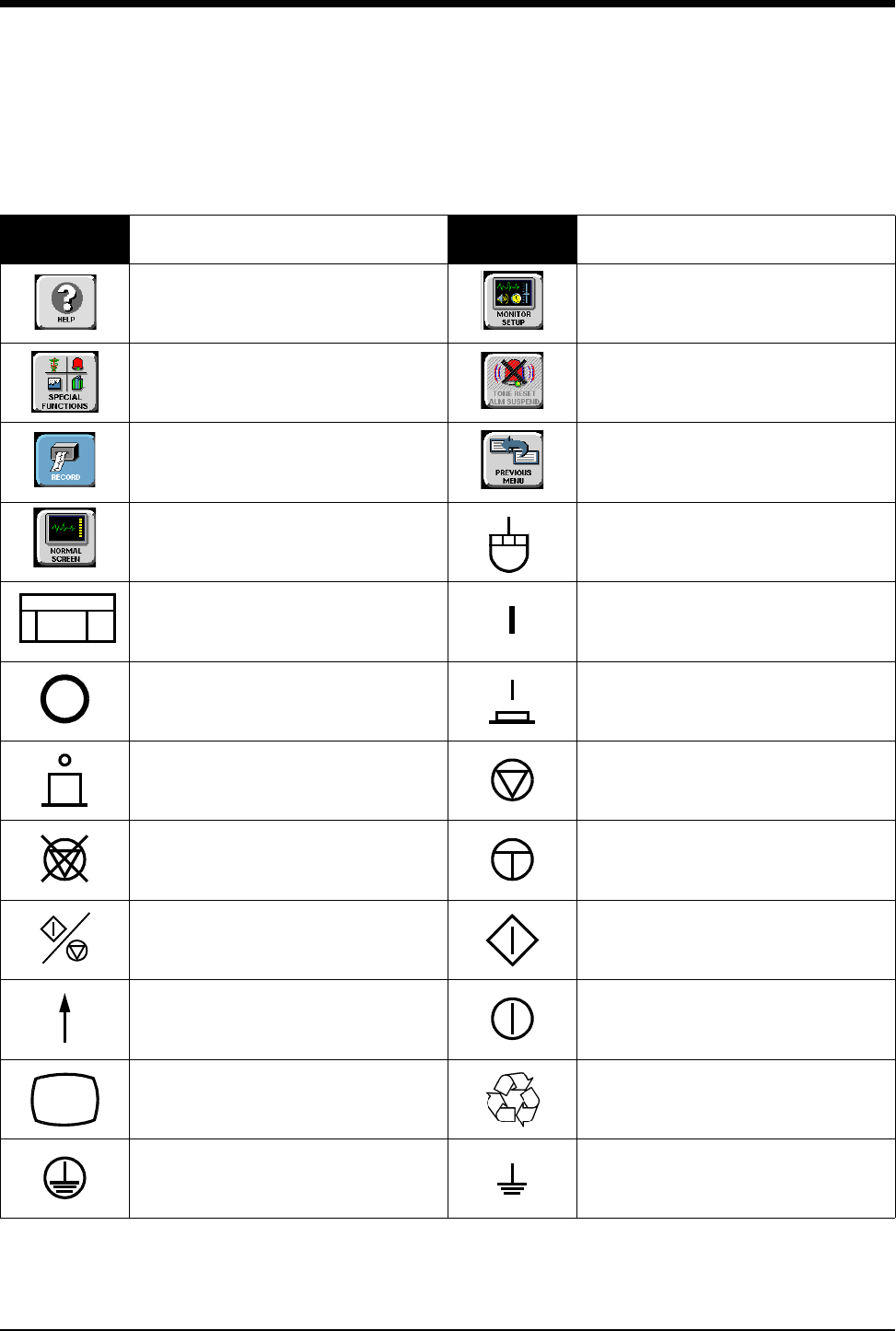
070-0774-00 Rev. A 6-1
Symbols
The following list of international and safety symbols describes all symbols used on Spacelabs Medical products. No one
product contains every symbol.
Symbol Description Symbol Description
UCW or Ultraview 1700
HELP Key
UCW or Ultraview 1700
MONITOR SETUP Key
UCW or Ultraview 1700
SPECIAL FUNCTIONS Key
UCW or Ultraview 1700
ALARMS Key
UCW or Ultraview 1700
RECORD Key
UCW or Ultraview 1700
PREVIOUS MENU Key
UCW or Ultraview 1700
NORMAL SCREEN Key
UCW or Ultraview 1700 mouse
connection
UCW or Ultraview 1700
Keyboard Connection ON — Power Connection to Mains
OFF — Power Disconnection from
Mains
On Position for Push button Power
Switch
Off Position for Push button Power
Switch STOP or CANCEL Key
CONTINUE Key START/STOP Key
START/STOP START (NIBP) Key
On Direction ON/OFF
Television; Video Display Recycle
Protective Earth Ground Functional Earth Ground
TOnE RESET
ALM SUSPEND
RECORD
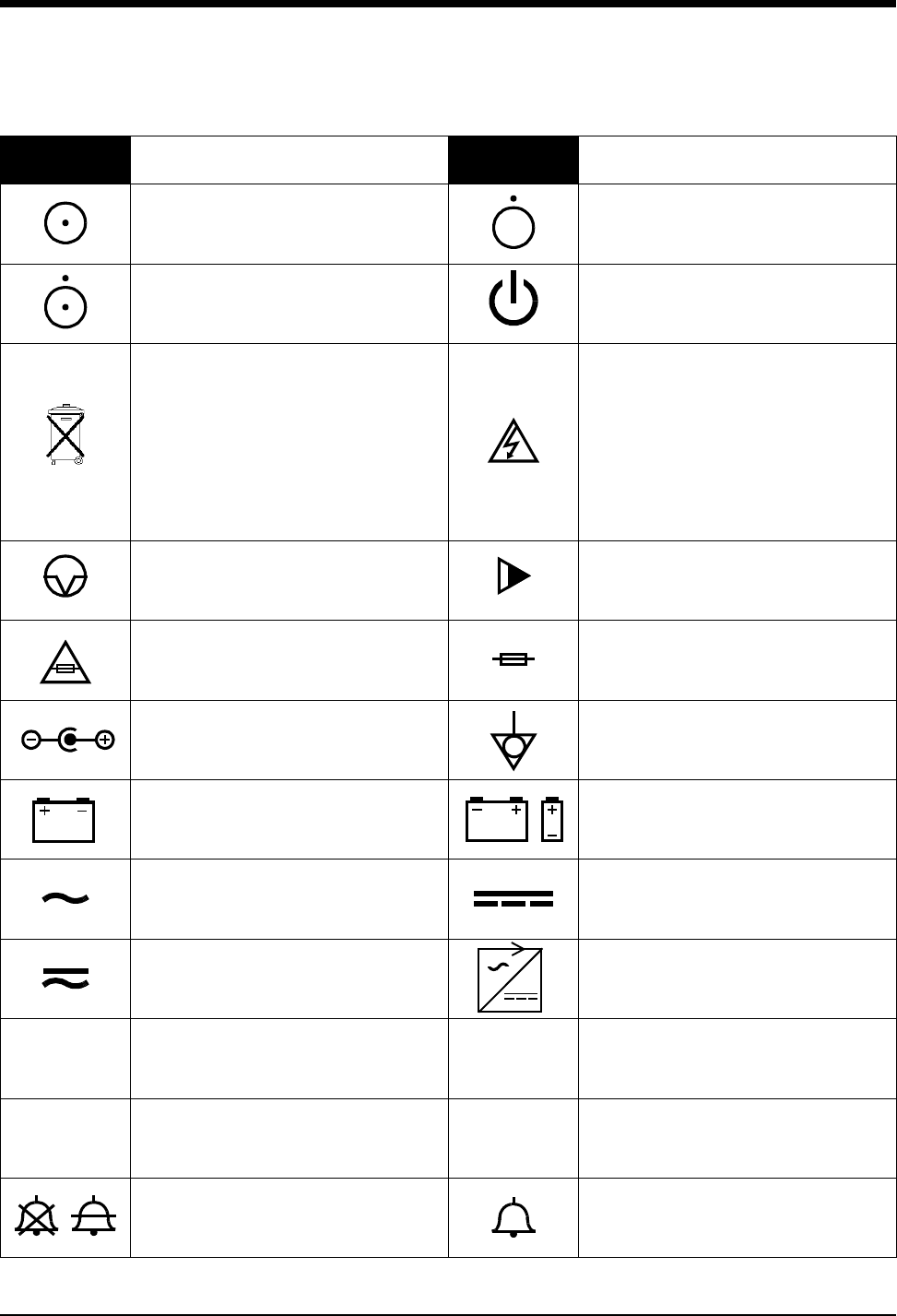
Ultraview Digital Telemetry
6-2 070-0774-00 Rev. A
ON — Part of the Instrument Only OFF — Part of the Instrument Only
Partial ON/OFF STAND-BY Key
All batteries should be disposed of
properly to protect the environment.
Lithium batteries should be fully
discharged before disposal. Batteries
such as lead-acid (Pb) and nickel-
cadmium (Ni-Cd) must be recycled.
Please follow your internal procedures
and or local (provincial) laws regarding
disposal or recycling.
Caution - hazardous voltages. To reduce
risk of electric shock, do not remove the
cover or back. Refer servicing to a
qualified service personnel (U.S.A.).
DANGER - High Voltage (International)
PAUSE or INTERRUPT Slow Run
Replace Fuse Only as Marked Fuse
Power supply jack polarity.
(+ / - Signs May be Reversed) Equipotentiality Terminal
Battery
Replace only with the appropriate
battery.
Replace only with the appropriate
battery.
(+ / - Signs May be Reversed)
Alternating Current Direct Current
Both Direct and Alternating Current AC/DC Input
Amperes Hertz
Volts Watts
Temporary Shut Off of Alarm Tone or
Screen Indicators Alarm
Symbol Description Symbol Description
AHz
VW
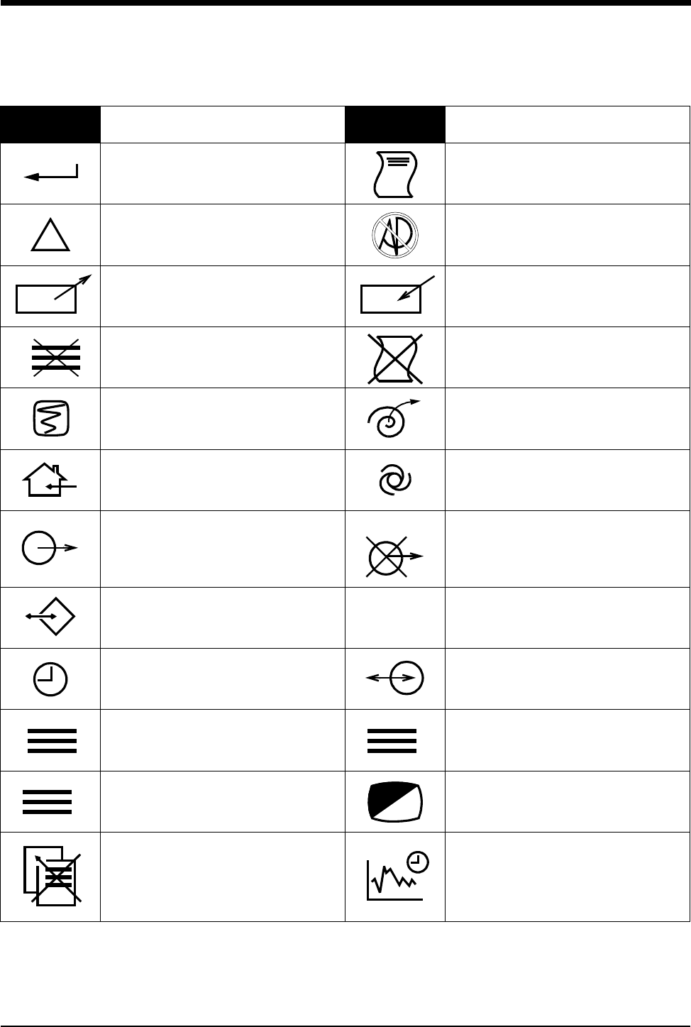
Symbols
070-0774-00 Rev. A 6-3
ENTER Key PRINT REPORT Key
Attention - Consult Operations or
Service Manual for Description
Risk of Explosion if Used in the
Presence of Flammable Anesthetics
Indicator — Remote control Indicator — Local Control
Return Unit to Monitor Mode Indicator — Out of Paper
Activate Recorder for Graphics Recorder Paper
Indoor Use Only Auto Mode (NIBP)
Output No Output (Terminated)
Data Input/Output HELP (Explain Prior Screen) Key
Clock/Time Setting Key Input/Output
Monitor Setup
Select Program Options Set Initial Conditions Menu
Access Special Function Menu Normal Screen
Return to Prior Menu TREND/TIMER Key
Symbol Description Symbol Description
!
1
2
3
?
1
2
3
1
2
3
A
1
2
3
B
1
2
31
2
3
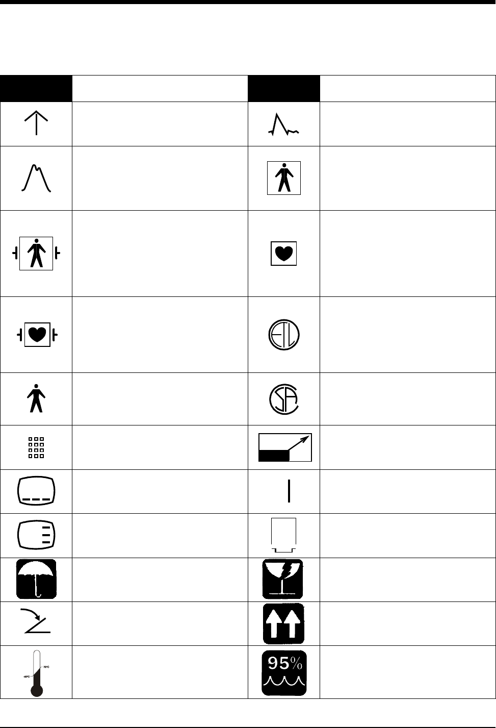
Ultraview Digital Telemetry
6-4 070-0774-00 Rev. A
Gas Exhaust Electrocardiograph or
Defibrillator Synchronization
Arterial Pulse
IEC 601-1 Type BF equipment. The unit
displaying this symbol contains an F-
type isolated (floating) patient-applied
part providing an adequate degree of
protection against electric shock.
IEC 601-1 Type BF equipment which is
defibrillator-proof. The unit displaying
this symbol contains an F-type isolated
(floating) patient-applied part which
contains an adequate degree of
protection against electric shock, and is
defibrillator-proof.
IEC 601-1 Type CF equipment. The unit
displaying this symbol contains an F-
type isolated (floating) patient-applied
part providing a high degree of
protection against electric shock.
IEC 601-1 Type CF equipment. The unit
displaying this symbol contains an F-
type isolated (floating) patient-applied
part providing a high degree of
protection against electric shock, and is
defibrillator-proof.
ETL Laboratory Approved
IEC 601-1 Type B equipment. The unit
displaying this symbol contains an
adequate degree of protection against
electric shock.
Canadian Standards Association
Approved
Keypad Enlarge, Zoom
Menu Keys Delete
Waveform/Parameter Keys PCMCIA Card
Keep Dry Fragile; handle with care
Foot Switch This Way Up
Environmental Shipping/Storage
Temperature Limitations
Environmental Shipping/Storage
Humidity Limitations
Symbol Description Symbol Description
x
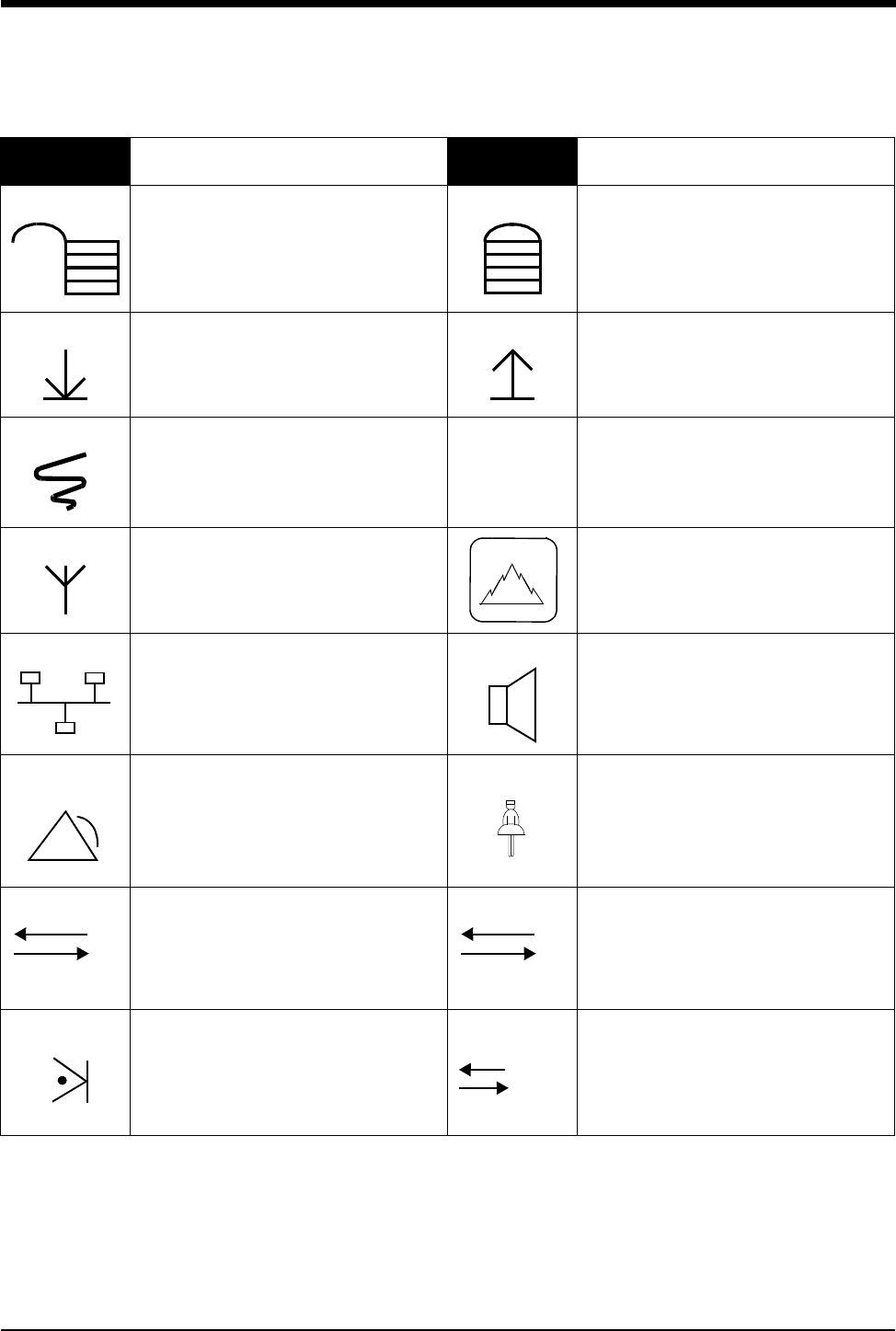
Symbols
070-0774-00 Rev. A 6-5
Open Padlock Closed Padlock
Down Arrow Up Arrow
Event TEMP
temp Temperature
Antenna Environmental Shipping/Storage
Altitude Limitations
Network Connection Audio Output, Speaker
Remote Alarm; Nurse Alert Nurse Call
Serial Port 1 Serial Port 2
External marker push button connection SDLC Port
Symbol Description Symbol Description
12,200 m
1 2
SDLC
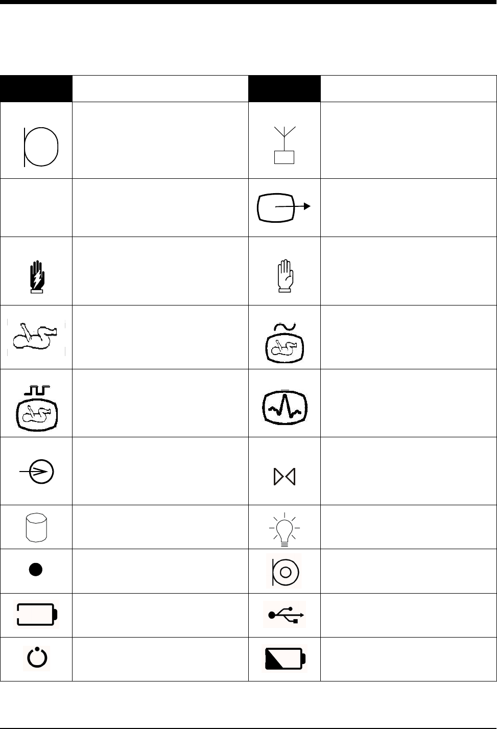
Ultraview Digital Telemetry
6-6 070-0774-00 Rev. A
Microphone Mermaid Connector
Note Video Output
Warning About Potential Danger to
Human Beings
Caution About Potential Danger to
Equipment
Non-Invasive Blood Pressure (NIBP),
Neonate Fetal Monitor Connection (Analog)
Fetal Monitor Connection
RS232 (Digital)
Physiological Monitor Connection
RS232 (Digital)
Input Reset
Hard Drive Power Indicator LED
Activate Telemetry Recorder Omnidirectional Microphone
Battery Status Universal Serial Bus
Stand-by Low Battery
Symbol Description Symbol Description
!

Symbols
070-0774-00 Rev. A 6-7
Abbreviations used as symbols are shown below.
Symbol Description Symbol Description
1 - 32 Access Codes
1 Through 32 AIR Air
ANT 1
ANT 2
Diversity Antenna System 1
Diversity Antenna System 2
Arr1
ArrNet2
Arrhythmia Net 1
Arrhythmia Net 2
CH
ch
EEG, EMG, or ECG Channel
EEG Channels - CH1, CH2, CH3, CH4
EMG Channel - CH5
cmH2OCentimeters of Water
CMV Controlled Mechanical Ventilation
C.O.
CO
co
Cardiac Output
DIA
dia Diastolic ECG
ecg Electrocardiogram
EEG
eeg Electroencephalogram EMG
emg Electromyogram
ESIS Electrosurgical Interference
Suppression EXT External
FECG Fetal Electrocardiogram FHR1
FHR2
Fetal Heart Rate, Channel 1
Fetal Heart Rate, Channel 2
GND
gnd Patient Isolated Ground HLO
hlo High-Level Output
I:E Inspiration Expiration Ratio MULTIVIEW Multi-Lead Electrocardiogram
NIBP
nibp Non-Invasive Blood Pressure N2ONitrous Oxide
O2Oxygen PEEP Positive End Expiratory Pressure

Ultraview Digital Telemetry
6-8 070-0774-00 Rev. A
BirthNet, Caremaster, Chartmaster, CVScan, Data Shuttle, FT1000, FT3000, Flexchart, Flexform, Flexport, Flextable,
Flextool, Flexview, Global Participant Index, Intesys, Multiview, Neochart, Neoscan, OR Chart, PCMS, PrintMaster,
Quicknet, Spaceview, Sensorwatch, TRU-CAP, TRU-CUFF, TRU-LINK, UCW, Ultralite, Ultraview, Ultraview Care Network,
Ultraview Clinical Messenger, Uni-Pouch, Universal Flexport, Varitrend, Vita-Stat, Web Source and WinDNA are
trademarks of Spacelabs Medical, Inc.
Other brands and product names are trademarks of their respective owners.
PRESS
press
PRS
Pressure Pmin Minimum Inspiratory Pressure
Ppeak Peak Inspiratory Pressure RESP
resp Respiration
SDLC Synchronous Data Link Control
SPO2
SpO2
SpO2
SaO2
Arterial Oxygen Saturation
as Measured by Pulse Oximetry
SVO2
SvO2
SvO2
Mixed Venous Oxygen Saturation SYS
sys Systolic
T1
T2
T3
T4
Temperature 1
Temperature 2
Temperature 3
Temperature 4
UA Uterine Activity or Umbilical Artery
VAC Vacuum connection
Symbol Description Symbol Description