Spacelabs Healthcare 76A91343-600 91343-05, 91347-05 User Manual Exhibit G 1
Spacelabs Healthcare, Inc. 91343-05, 91347-05 Exhibit G 1
Contents
- 1. User Manual 1
- 2. User Manual 2
User Manual 1
Exhibit G: User Manual 1
FCC ID: CM676A91343-600
Page 1 of 6
Ultraview
Digital
Telemetry
91341, 91343,
91347, 90478,
90479-A
■Operation in the Wireless Medical
Telemetry Service (WMTS) bands
(608-614, 1395-1400, 1427-1429.5,
1429-1431.5 MHz).
■Approved to operate under FCC Part
95 rules.
■ECG and multiparameter transmitter.
■ECG, SpO2, and NIBP (optional) for
ambulatory patients.
■Touchscreen control of all module
functions and compatible with all
Ultraview Care Network™ monitors.
■Lightweight, water resistant
transmitters.
■Tunable transmitters.
■Diversity antenna system.
■Tunable modular receiver.
■Modular receiver converts bedside
monitors to telemetry operation.
■Multi-lead ECG with ST segment
analysis option; comprehensive
arrhythmia and ST trending.
■Module Configuration Manager
enables the hospital to customize the
receiver’s ECG patient monitoring
functions to specific patient
populations, clinical protocols, or
operating preferences.
■Graded alarm functions enables the
hospital to define high, medium, or
low alarm tones according to critical,
warning, or advisory event severity.
■Expanded central monitoring of
ambulatory patients outside central
antenna coverage.
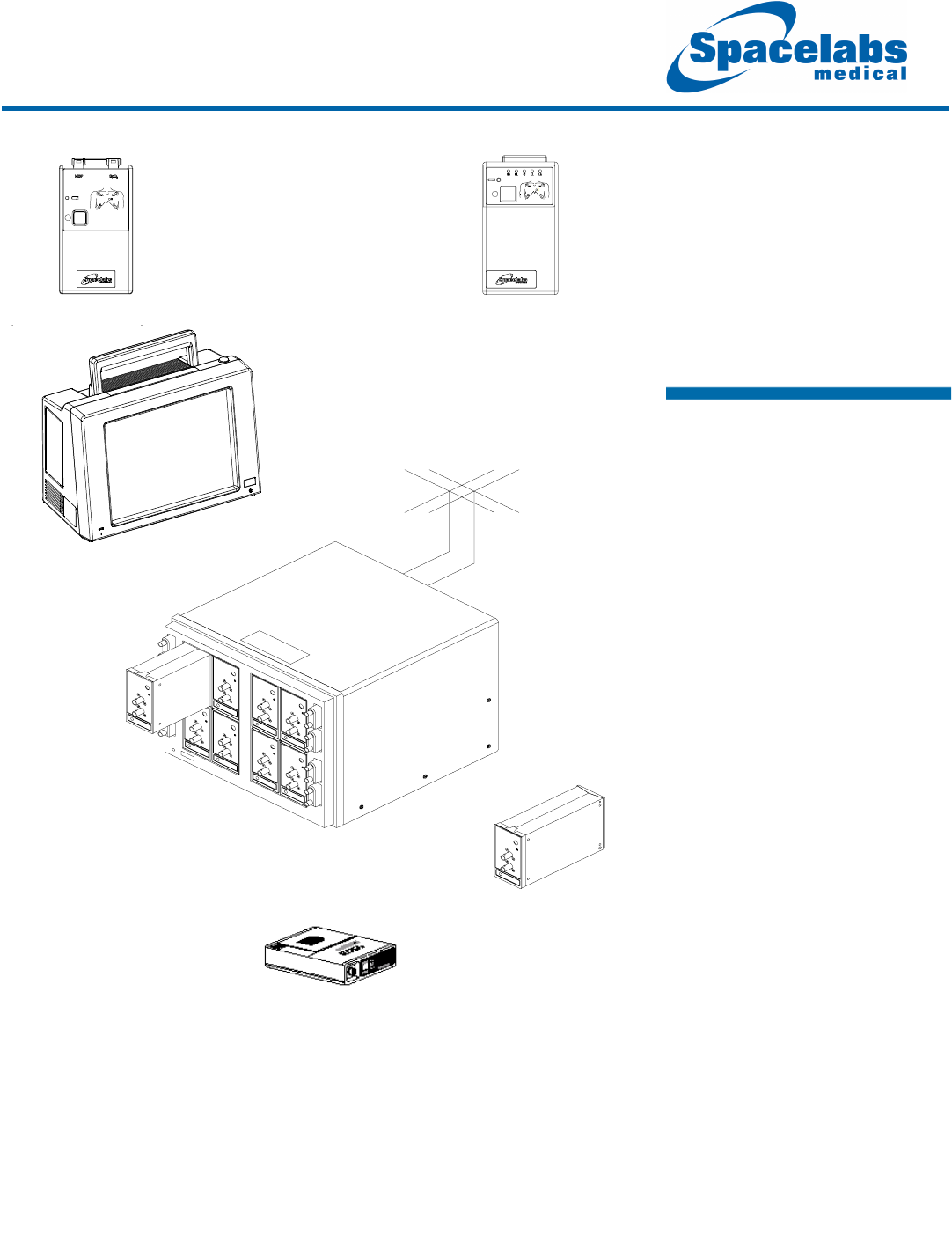
Diversity Antenna
System
90217 ABP Monitor
90478 Modular Receiver
Receiver Housing
91343
Digital
Telemetry
Multiparameter
Transmitter
91341/47
Digital
Telemetry
ECG
Transmitters
90479-A Modular
Ultraview 1030/1050
®

SPECIFICATIONS
Ultraview
Digital
Telemetry
91341,
91343,
91347,
90478,
90479-A
Page 2 of 6
PARAMETER CHARACTERISTICS
ECG
Maximum Input — ±4 mV ( ±10%)
DC Offset — Up to ±300 mV, with no more than
2% signal amplitude degradation
Overdrive Recovery Time — < 1 second
circuit settling time with offset voltage < 500
mV
Noise — < 30 µV p-v, refered to input (rti), at 30
Hz bandwidth
CMRR — > 85 dB (monitor mode)
QRS Detection — Detects QRS complexes
with durations of 40 to 120mS and
amplitudes of 0.2 to 4.0 mV (adult) or 0.15 to
4.0 mV (neonatal)
Defibrillator Protection — Meets IEC
60601-2-27, AAMI EC-13
Resolution — 2.5 µV per LSB, rti
Input Impedance — > 10 MΩ minimum
differential at 10 Hz
Gain Accuracy — ±5%
Pacer Rejection — Baseline shift < 0.2 mV
(measured at ECG x 1,000 output)
Pacer Detection — Detects pacer pulses of ±2
mV to ±700 mV with pulse widths of 0.2 to 2
msec and rise times 10% of width not to
exceed 100 µsec.
Signal Bandwidth — 0.05 to 30 Hz
±10% (-3 dB)
Sample Rate — 120 samples per second
SpO2
SpO2 Sensor Interface —
Red LED drive (max): 175 mA peak at 10%
duty cycle
IR LED drive (max): 105 mA peak at 10%
duty cycle
SpO2 Measurement Method — Functional
saturation (oxygen saturation of functional
hemoglobin).
SpO2 Measurement Mode — Continuous,
episodic (2 minutes, 5 minutes, and 30
minutes) sampling intervals; factory default
setting is continuous.
ST Segment Analysis
Resolution — 0.08 mm
Range — ±9 mm (1 mV = 10 mm)
Leads — ST Segment Analysis continously
performed on up to seven leads.
Alarms — Single lead or multiple leads;
individual leads can be deselected. Alarms
for absolute minimum and maximum ST
levels; changes in ST level over the last 5
minutes.
Displays — ST values: minimum/maximum/
current ST segment deviation and 5 minute
averaged segments for the last 30 minutes.
Measurement Points — Adjustable ST, PR,
and J Points
Trends — Up to 24 hours of trend data can be
displayed in 1.5-, 3-, 6-, 12-, or 24-hour time
tracks.
PATIENT MONITOR DISPLAY
CHARACTERISTICS
ECG Display
Heart Rate Range — 30 to 300 bpm; heart
rates > 300 bpm are displayed as “+++”.
Heart Rate Alarm Limits — High: 5 to 300
bpm, Low: 0 to 200 bpm; alarms
automatically enabled over a range of 40
(adult) or 100 (neonatal) to 300 bpm; heart
rates > 300 bpm are displayed as “+++”.
Accuracy — ±1% or ±2 beats per minute
(whichever is greater).
Numeric Update Rate — Every 3 seconds or
immediately at the onset of an alarm.
Trace Sweep Speeds — 50, 25, 12.5 mm/sec
Display Bandwidth — Two settiings: 0.5 to 30
Hz ±10% (-3 dB) in monitor mode, and 0.05
to 30 Hz ±25% (-3 dB at 50 mm per second)
in extended mode.
SpO2 Display
Measurement Range — 30 to 100% O2
Saturation
Saturation Accuracy — Sensor Dependent
Saturation Resolution — ±1%
Pulse Rate Range — 30 to 250 bpm
Pulse Rate Resolution — 1 bpm
Alarms — High and low saturation values;
factory default limits are: high 100%; low
85%.
High range: 31% – 100%
Low range: 30% – 99%
Numeric Update Rate — Every 2 seconds for
continuous SpO2 readings.

SPECIFICATIONS Ultraview
Digital
Telemetry
91341,
91343,
91347,
90478,
90479-A
Page 3 of 6
NIBP Display
(Refer to specifications for the 90217 ABP
Monitor)
Measurement Range (adult only) —
Systolic: 8.0 – 35.0 kPa
(60 – 260 mmHg)
Diastolic: 9.0 – 27.0 kPa
(30 – 200 mmHg)
Mean: 5.3 – 31.0 kPa
(40 – 230 mmHg)
Pressure Accuracy — ±2% or ±3 mmHg
(whichever is greater)
Resolution — 1 mmHg
Time Between Readings — selectable, from 6
to 120 minutes
Alarms — High and low alarms for all
measured parameters.
High range: 8.0 – 35.0 kPa
(60 – 260 mmHg)
Low range: 4.0 – 27.0 kPa
(30 – 200 mmHg)
TRANSMITTERS (91341, 91343, 90347)
ECG Transmission — View 2 of 7 available
leads from two vectors (91341) or four
vectors (91343, 91347) synchronized RF
digital signal.
Electrode Configuration — Individually
replaceable DIN standard safety lead wires.
Local lead fault indicators for each lead wire.
Multiparameter Transmission (90343) —
SpO2 (saturation, SpO2 sensor status, pulse
rate) and optional NIBP (systolic, diastolic,
mean pressure, measurement time, alarm
conditions) with the model 90217 ABP
monitor.
Additional Data Transmitted — Patient
record, low battery indicator, pacer flag,
patient ID code, and electrode connection
status.
Output Power — 1 mW ERP, typical
Spectral Efficiency — 0.11 bps/Hz
External Indicator — Yellow LED flashes
when battery level is low
Battery — 9 V battery; refer to Table 1 for
battery life expectancy
WMTS Frequency Band Option —
-05: 608-614 MHz
-09: 1395-1400 MHz
1427-1429.5 MHz
1429-1431.5 MHz
Transmitter Physical Dimensions
91343 (Multiparameter)
Height: 5.25 in (13.3 cm)
Width: 2.85 in (7.2 cm)
Depth: 1.18 in (2.9 cm)
Weight (w/out battery):
8.5 oz (241.0 gm)
91341/47 (ECG-only)
Height: 5.25 in (13.3 cm)
Width: 2.85 in (7.2 cm)
Depth: 0.98 in (2.5 cm)
Weight (w/out battery):
6.78 oz (192.7 gm)
MODULAR RECEIVER
Module Includes:
Module Configuration Manager capability
(refer to the Module Configuration Manager
chapter of the Ultraview Care Network
Operations Manual [P/N 070-1001-16] for
complete feature specifications).
Trends — (with appropriate mainframe option)
24 hours of trended data can be displayed in
1.5-, 3-, 6-, 12-, or 24-hour segments; data is
stored in 1-minute resolution.
High Level Analog Output —
ECG 1: Used for defibrillator
synchronization
Connector: 3-conductor TT phone jack
Dynamic Range: ±5 mV (±10%), rti
Gain: ECG x 1000 (±5%)
Bandwidth: 0.05 to 30 Hz
±10% (-3 dB)
Module Parameter Count — This module
counts as 1 or 2 parameters when computing
parameter capacity for monitors.
1 displayed ECG lead = 1 parameter.
2 displayed ECG leads = 2 parameters.
Receiver Sensitivity — Usable ECG signal to
-95 dBm

SPECIFICATIONS
Ultraview
Digital
Telemetry
91341,
91343,
91347,
90478,
90479-A
Page 4 of 6
Receiver Options —
The following system configuration options are
available in the 90478.
A — Basic Arrhythmia: High and low heart
rate, asystole and ventricular fibrillation
(2 leads).
B — Multiview™ I Arrhythmia — Enables
users to review trends of abnormals per
minute; provides additional alarms for
abnormals per minute and abnormals in a
row (2 leads).
C — Multiview II Arrhythmia — Enables users
to review the dominant morphology as well as
episodes or classes of ventricular fibrillation,
ventricular tachycardia (runs), couplets,
single abnormals, tachycardia, pauses,
ventricular and atrio-ventricular pacing;
provides additional alarms for abnormals in a
row, abnormals per minute, and tachycardia
(2 leads).
S — ST segment analysis/review/trend
(2 leads).
Q — Band operation, 608 to 614 MHz
T — Band operation, 1395 to 1400 MHz
V — Band operation, 1427 to 1431.5 MHz
Receiver Electrical Requirements
Power Consumption — ≤ 5.0 watts
External Indicators — LED lights when user
accesses control.
Receiver Physical Dimensions
Height: 4.46 in (11.32 cm)
Width: 2.24 in (5.68 cm)
Depth: 7.00 in (17.78 cm)
Weight: 2.4 lbs (1.11 kg)
Receiver Housing (90479-a)
Accommodates up to 8 modular receivers.
Housing Physical Dimensions
Height: 12.0 in (30.5 cm)
Width: 13.5 in (34.3 cm)
Depth: 17.5 in (44.5 cm)
(includes protective cover)
Weight: 32.0 lbs (14.6 kg)
(without modules loaded)
Receiver Housing Power Requirements
100–120 VAC, 50/60 Hz, 2A; 220–240 VAC,
50/60 Hz, 1A
ENVIRONMENTAL REQUIREMENTS
Operating —
Temperature: 50° to 104° F (10° to 40° C)
Humidity: 95% (non-condensing)
Altitude: 0 to 10,000 ft (0 to 3,030.3
m)
Storage —
Temperature: -40° to 149° F (-40° to 75°
C)
Humidity: 100% (non-condensing)
Altitude: -500 to 40,000 ft (-151.5 to
12,121.2 m)
Water Resistance:
Meets EN60529 IPX1
REGULATORY APPROVALS
All models are ETL listed and meet UL544 or
UL2601-1 standard for electrical safety;
approved by CSA; Models 91341, 91343,
90347, and 90478, approved by FCC and
Industry Canada (RSS - 210, 608-614 MHz
operation only).
ACCESSORIES
Please refer to the Spacelabs Medical Supplies
Catalog for availability of ECG lead wires and
electrodes, blood pressure cuffs, and SpO2
sensors from Spacelabs Medical.
91341/91343/91347 Transmitter Pouch
Part Number: 015-0500-00
DIN Standard Safety ECG Lead Wire Set
(5 wire) 25.2-inch snap
Part Number: 012-0605-00
Receiver Housing Protective Cover
Part Number: 200-0180-00
Whip Antenna (UHF) 608 to 614MHz
Part Number: 117-0040-00
Belt Clip
Part Number: 344-0020-00
SpO2 Adapter Cable (Nellcor)
Part Number: 700-0014-00
ABP Telemetry Adapter Cable
Part Number: 700-0015-00
ABP Pouch
Part Number: 015-0501-00
ABP Shoulder Strap
Part Number: 016-0262-00
ABP Waist Belt
Part Number: 016-0080-00

SPECIFICATIONS Ultraview
Digital
Telemetry
91341,
91343,
91347,
90478,
90479-A
Page 5 of 6
ABP Report Management System
Part Number: 90121ABP Report
Management System Adaptor Cable
Part Number: 012-0097-02
ABP Adult Adapter Assembly
Part Number: 714-0017-00
Nellcor SpO2 Sensor Accuracy and Sensor
Selections
Nellcor Reusable SpO2 Sensors —
Finger Clip (DS-100A) (P/N 690-0003-00)
70–100%, ±3% absolute saturation
OXIBAND A/N (OXI-A/N) (P/N 690-0004-00)
70–100%, ±3% absolute saturation
OXIBAND P/I (OXI-P/I) (P/N 690-0039-00)
70–100%, ±3% absolute saturation
Nellcor Disposable SpO2 Sensors —
Adult (N-25) (P/N 690-0006-00)
70–100%, ±2% absolute saturation
Neonatal (N-25) (P/N 690-0006-00)
70–100%, ±3% absolute saturation
Pediatric (D-20) (P/N 690-0007-00)
70–100%, ±2% absolute saturation
Adult (D-25) (P/N 690-0001-00)
50–69%, ±3% absolute saturation
70–100%, ±2% absolute saturation
Nasal (R-15) (P/N 690-0005-00)
80–100%, ±3.5% absolute saturation
Infant (I-20) (P/N 690-0002-00)
50–69%, ±3% absolute saturation
70–100%, ±2% absolute saturation
1 Operational service life (in hours) assuming a new
alkaline battery (minimum 580 mAH capacity) or
lithium battery (minimum 1200 mAH capacity) used
until the local low battery indicator begins to flash.
2 NIBP operations from a 90217 ABP Monitor sending
readings to the 91343 Multi-parameter telemetry
transmitter. The 90217 ABP monitor will inflate a
standard size adult cuff at least 240 times with
alkaline batteries.
Table 1: Transmitter Battery Service Life1 (hours)
Battery
Type 9 Volt Alkaline (ANSI/NEDA 1604A) 9 Volt Lithium (ANSI/NEDA 1604LC)
Load
Con-
ditions2ECG
Only
ECG
and
Con-
tinuous
SpO2
ECG and
2 minute
Episodic
SpO2
ECG and
5 minute
Episodic
SpO2
ECG and
30 minute
Episodic
SpO2 and
NIBP
ECG
Only
ECG
and
Con-
tinuous
SpO2
ECG
and 2
minute
Episodic
SpO2
ECG
and 5
minute
Episodic
SpO2
ECG
and 30
minute
Episodic
SpO2
91343 48 24 36 38 40 120 60 100 104 106
91341/47 52 Not
Applicable
Not
Applicable
Not
Applicable
Not
Applicable 132 Not
Applicable
Not
Applicable
Not
Applicable
Not
Applicable
Medical telemetry spectrum allocations may be assigned to frequencies already allotted to other priority
users. This means that telemetry operations may be exposed to radio frequency interference that may
disrupt or impede telemetry patient monitoring. Additionally, medical telemetry spectrum allocations
may be changed by government action and Spacelabs Medical accepts no responsibility for such
changes, including the possibility that the product may not operate in the modified permissible
spectrum ranges other than those expressly set forth in Spacelabs Medical’s published product data
sheets. Spacelabs Medical cannot, and does not, guarantee interference-free telemetry operation.

Ultraview
Digital
Telemetry
91341,
91343,
91347,
90478,
90479-A
Spacelabs Medical, Inc.
15220 N.E. 40th Street
P.O. Box 97013
Redmond, WA 98073-9713
Telephone: (425) 882-3700
Fax: (425) 885-4877
Telex: 4740085 SPL UI
Ultraview, Ultraview Care
Network, and Multiview are
trademarks of Spacelabs
Medical, Inc.
Other brands and product
names are trademarks of their
respective owners.
All specifications are subject to
change without notice.
www.spacelabs.com
© Spacelabs Medical, Inc. 2002
061-1317-00 Rev. A 07/2002
Page 6 of 6