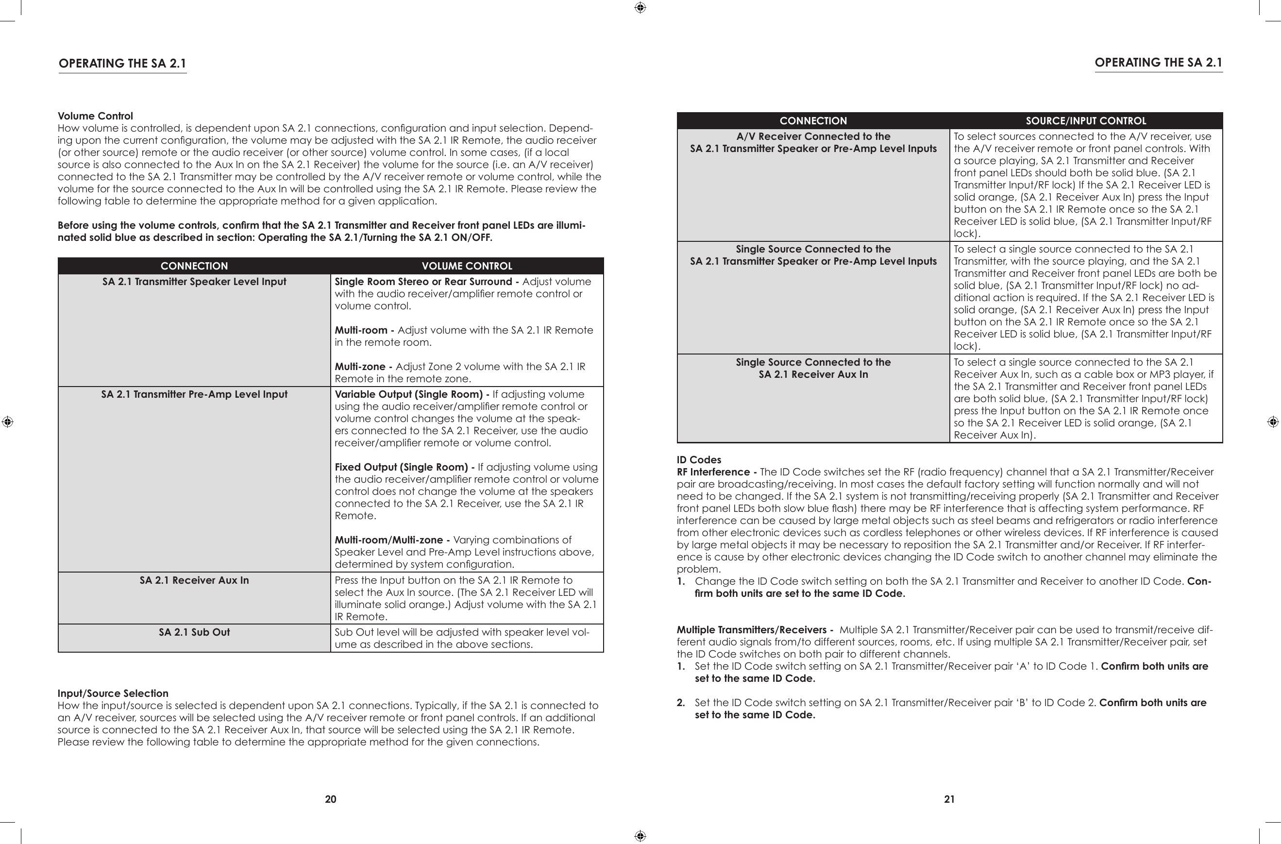
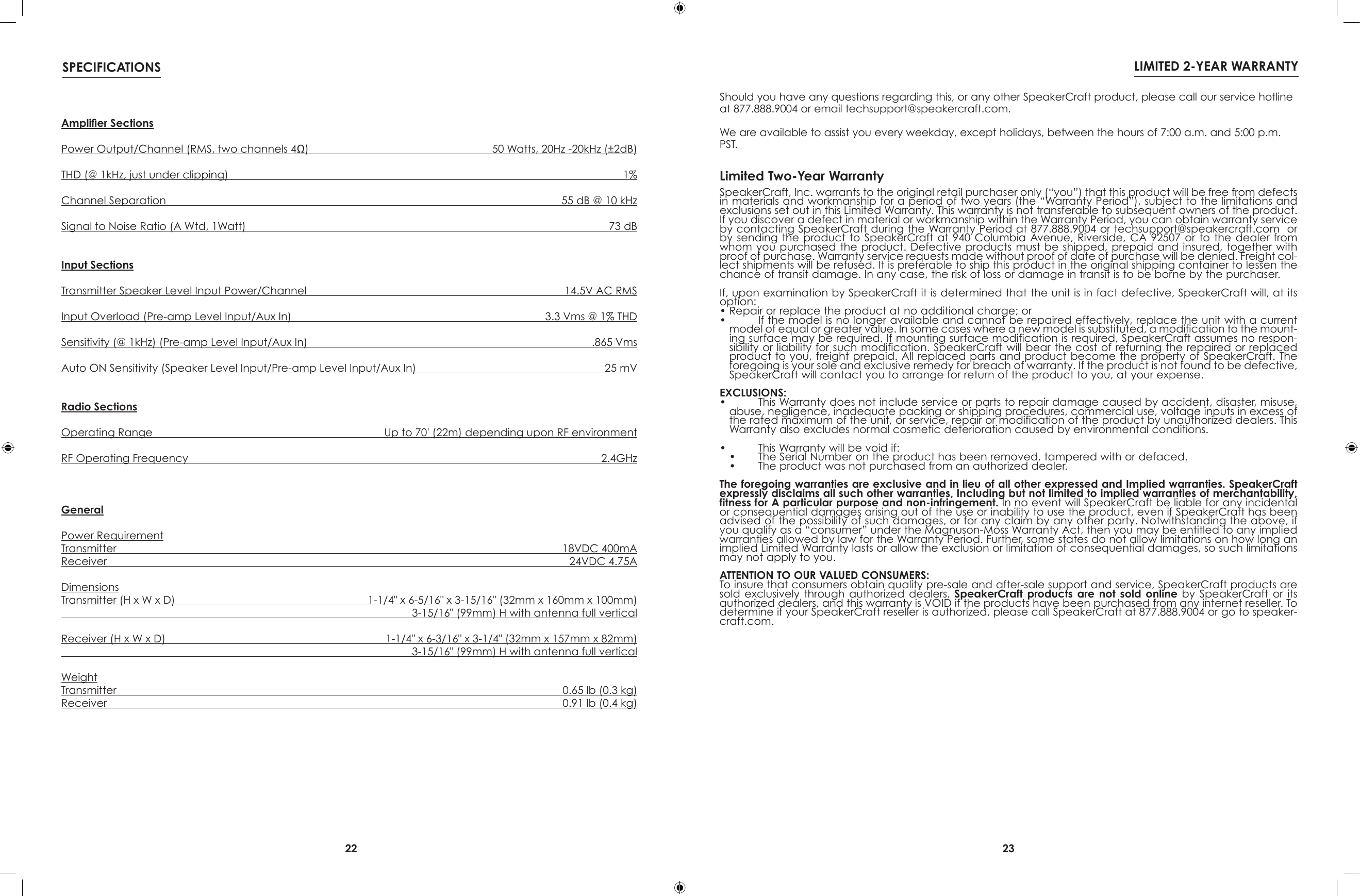
Speakercraft WRX SonicAir and Airflex (Wireless amplifier System) User Manual

Speakercraft, Inc. SonicAir and Airflex (Wireless amplifier System) Users Manual

Users Manual

INSTALLATION INSTRUCTIONSSonicAir SA 2.1Wireless Speaker Transmitter & Receiver
2 3This equipment has been tested and found to comply with the limits for a Class B digital device, pursuant to Part 15 of the FCC Rules. These limits are designed to provide reasonable protection against harmful interference in a residentialinstallation.This equipment generates, uses and can radiate radio frequency energy and, if not installed and used in accordance with the instructions, may cause harmful interference to radio communications. However, there is no guarantee that interference will not occur in a particular installation. If this equipment does cause harmful interference to radio or television reception, which can be determined by turning the equipment off and on, the user is encouraged to try to correct the interference by one or more of the following measures:•  Reorient or relocate the receiving antenna.•  Increase the separation between the equipment and receiver.•  Connect the equipment into an outlet on a circuit different from that to  which the receiver is connected.•  Consult the dealer or an experienced radio/TV technician for help.FCC Caution: To assure continued compliance, any changes or modications to this unit not expressly approved by the party responsible for compliance could void the user’s authority to operate the equipment. (Example - use only shielded interface cables when connecting to computer or peripheral devices.)FCC Radiation Exposure Statement:  this equipment complies with FCC radiation exposure limits set forth for an uncontrolled environment. This equipment should be installed and operated with a minimum distance of 20 centimeters between the radiator and your body.This transmitter must not be co-located or operating in conjunction with any other antenna or transmitter.the antenna used for this transmitter must be installed to provide a separation distance of at least 20 centimeters from all persons and must not be co-located or operating in conjunction with any other antenna or transmitter.FCC COMPLIANCE• Explanation of Graphical SymbolsThe lightning flash with arrowhead symbol, within an equilateral triangle, is intended to alert you to the presence of uninsulated “dangerous voltage” within the product’s enclosure that may be of sufficient magnitude to constitute a risk of electric shock to persons.The exclamation point within an equilateral triangle is intended to alert you to the presence of important operating and maintenance (servicing) instructions in the literature accompanying the product.APPLICABLE FOR USA, CANADA OR WHERE APPROVED FOR USAGECAUTION: TO PREVENT ELECTRIC SHOCK, MATCH WIDE BLADE PLUG TO WIDE SLOT, INSERT FULLY.ATTENTION: POUR EVITER LES CHOCS   ELECTRIQUES, INTRODUIRE LA LAME LA  PLUS LARGE DE LA FICHE DANS LA BORNE CORRESPONDANTE DE LA PRISE ET POUSSER JUSQU AU FOND. CAUTION: To reduce the risk of electric shock, do not remove cover (or back). No user-serviceable parts inside. Referservicing to qualified service personnel.1.  Read these instructions.2.  Keep these instructions.3.  Heed all warnings.4.  Follow all instructions.5.  Do not use this apparatus near water.6.  Clean only with a damp cloth.7.  Do not block any ventilation openings. Install in accordance with the manufacturer’s instructions.8.  Do not install near any heat sources such as radiators, heat registers, stoves, or other apparatus (including amplifiers) that produce heat.9.  Do not defeat the safety purpose of the polarized or grounding-type plug. A polarized plug has two blades with one wider than the other. A grounding-type plug has two blades and a third grounding prong. The wide blade or the third prong are provided for your safety. If the provided plug does not fit into your outlet, consult an electrician for replacement of the obsolete outlet.10.  Protect the power cord from being walked on or pinched particu-larly at plugs, convenience receptacles, and the point where they exit from the apparatus.11.  Only use attachments/accessories specified by the manufacturer.12.  Use only with the cart, stand, tripod, bracket, or table specified by the manufacturer, or sold with the apparatus. When a cart is used, use caution  when moving the cart/apparatus combination to avoid injury from tip-over.13.  Unplug this apparatus during lightning storms or when unused for long periods of time.14.  Refer all servicing to qualified service personnel. Servicing is required when the apparatus has been damaged in any way, such as power-supply cord or plug is damaged, liquid has been spilled or objects have fallen into the apparatus, the apparatus has been exposed to rain or moisture, does not operate normally, or has been dropped.15.  The apparatus shall not be exposed to dripping or splashing and that no objects filled with liquids, such as vases, shall be placed on the apparatus.16.  CAUTION: Servicing instructions are for use by qualified service per-sonnel only. To reduce the risk of electric shock, do not perform any servicing other than that contained in the operating instructions unless you are qualified to do so.17.  WARNING: To reduce the risk of fire or electric shock, do not expose this apparatus to rain or moisture.PORTABLE CART WARNINGSAFETY INSTRUCTIONS
4 5TABLE OF CONTENTSNOTESSAFETY INSTRUCTIONS ......................................................................................................................... 2FCC COMPLIANCE .............................................................................................................................. 3NOTES ................................................................................................................................................... 4TABLE OF CONTENTS ............................................................................................................................ 5INTRODUCTION .................................................................................................................................... 6WHAT’S INCLUDED ............................................................................................................................... 7SA 2.1 FEATURES .................................................................................................................................. 8 SA 2.1 Transmitter ............................................................................................................................... 8  SA 2.1 Receiver ................................................................................................................................ 10  SA 2.1 Remote Control .................................................................................................................... 12INSTALLATION .................................................................................................................................... 13  SA 2.1 Transmitter/Receiver Location & Transmission Range .................................................... 13  Mounting the SA 2.1 Receiver ...................................................................................................... 14  CONNECTIONS ............................................................................................................................... 16  SA 2.1 Transmitter/Receiver Connections .................................................................................. 16    Speaker Level Connections (SA 2.1 Transmitter) ....................................................................... 16    Speaker Level Connections (SA 2.1 Receiver) .......................................................................... 16 Line Level Connections (SA 2.1 Transmitter) .............................................................................. 17    Subwoofer Connections (SA 2.1 Receiver)................................................................................ 17    Aux In Connections (SA 2.1 Receiver) ........................................................................................ 18  Final Setup ...................................................................................................................................... 18   Position the Transmitter and Receiver ........................................................................................ 18    Antenna ......................................................................................................................................... 18    Power Supply Connections ......................................................................................................... 18OPERATING THE SA 2.1 ...................................................................................................................... 19 Turning the SA 2.1 ON/OFF ............................................................................................................. 19  Front Panel LEDs ............................................................................................................................... 19  Volume Control ................................................................................................................................ 20  Input/Source Selection ................................................................................................................... 20  ID Codes ........................................................................................................................................... 21SPECIFICATIONS ................................................................................................................................ 22LIMITED 2-YEAR WARRANTY .............................................................................................................. 23
6 7WHAT’S INCLUDEDINTRODUCTIONWHAT’S INCLUDEDTransmitter  1 - SA 2.1 Transmitter  1 - 18VDC 400mA Power SupplyReceiver  1 - SA 2.1 Receiver  1 - 24VDC 4.75A Power Supply  1 - SA 2.1 IR Remote1 - SA 2.1 Installation InstructionsSA 2.1 FEATURESTransmitterInputs/ConnectionsSpeaker Level - 4 ve-way binding postsPre-Amp Level - 2 RCA jacksPower - 2.1mm coaxial jackStatusMulti-color front panel LEDTransmission RangeUp to 70 feet depending upon RF environmentID CodeFour position RF channel selectorReceiverAudio Amplier50 Watts per channel x 2Outputs/ConnectionsSpeaker Level - 4 ve-way binding postsSub Out - 3.5mm stereo mini jackPower - 2.1mm coaxial jackLocal Audio InputAux In - 1 stereo 3.5mm mini jackStatusMulti-color front panel LEDID CodeFour position RF channel selectorIR RemoteVolumeMuteInputAux InCongratulations and thank you for purchasing the SpeakerCraft SonicAir SA 2.1 Wireless Speaker Transmitter and Receiver System!The SA 2.1 solves the age-old problem of how to put speakers where you want them without having unsightly speaker wire run around baseboards, across the oor or having to pull them through walls.The SA 2.1 Transmitter can connect to just about any audio source. It then broadcasts audio content as wireless RF (radio frequency) signals to the SA 2.1 Receiver, that can be placed up to seventy feet away (depending upon the local RF environment).The SA 2.1 Transmitter features both stereo line level and speaker level audio inputs. The Pre-Amp and Speaker Level Inputs both feature audio sensing circuitry that automatically turns the SA 2.1 system on when audio input signals are detected. The system will automatically turn off (standby) when no audio signals have been detected for more than ten minutes.In addition to regular stereo speaker applications, the speaker level inputs provide convenience for A/V system rear speaker placement in surround sound systems. The SA 2.1 Transmitter can be con-nected to the rear channel speaker terminals on the A/V receiver and then broadcast the rear chan-nel speaker signals to the SA 2.1 Receiver, located with the rear channel speakers. This eliminates hav-ing unsightly and potentially hazardous speaker wires run around baseboards or across the oor.The SA 2.1 system also increases the exibility of an audio system from a single room system to a multi-room system. With an audio receiver directly connected to the main room speakers in a normal con-guration, the audio receiver ‘B’ speakers or pre-amp output can be connected to the SA 2.1 Trans-mitter for broadcast to the SA 2.1 Receiver in the second room, creating a multi-room audio system without having to pull wires!The SA 2.1 Receiver adds additional exibility with its local Auxiliary Input. With the SA 2.1 system congured as a multi-room system, this line level, stereo 3.5mm mini jack allows connection of a lo-cal source in the remote room. This allows selection of the ‘house’ system audio source or the local source which could be a CD or MP3 player, video game, computer, cable box, or any other audio source with a line level output. The SA 2.1 Receiver is controlled locally with the SA 2.1 IR Remote, al-lowing independent source selection and volume/mute control in the remote room.The SA 2.1 Receiver has a solid built-in 50 Watts per channel amplier that will make any audio source sound great when driven through appropriately rated 8 ohm speakers.For those who want some extra kick, the SA 2.1 Receiver also features a full-band Sub Out that can be connected to a subwoofer with a line level input, and variable level and crossover controls. This ‘wireless subwoofer’ application allows optimizing main room subwoofer placement, without the restriction of having to run unsightly audio cable to the sub. The SA 2.1 Receiver Sub-Out adds that same exibility to multi-room applications, allowing not only the addition of a subwoofer to the sec-ond room, but unrestricted placement for optimum performance and convenience. The pre-installed Receiver Clip and included Mounting Bracket allow convenient and inconspicuous mounting of the SA 2.1 Receiver directly to a powered subwoofer.The SpeakerCraft SonicAir SA 2.1 Wireless Speaker Transmitter and Receiver System gives you music where you want it...not just where the speaker wires are.Please read and follow the instructions in this guide to assist in proper installation, connection and use of the SpeakerCraft SonicAir SA 2.1 Wireless Speaker Transmitter and Receiver System.
8 9SONICAIR SA 2.1 FEATURES SONICAIR SA 2.1 FEATURES1SA 2.1 TransmitterThe SA 2.1 Transmitter connects to the line level audio or speaker level outputs on an A/V or audio receiver, CD player, MP3 player, video game, computer audio card or other audio device to broadcast stereo audio signals to speakers in the main room or another location when running speaker wire is not convenient or possible.The SA 2.1 Transmitter is located with the audio source and positioned for optimum performance and must be connected to an AC outlet.The SA 2.1 Transmitter converts audio con-tent to RF (Radio Frequency) signals and  SA 2.1 Transmitter Front Panel FeaturesFigure 1  SA 2.1 Transmitter Front Panel Features1.  POWER LED - This multicolored LED has multiple modes to indicate SA 2.1 Transmitter status.  SOLID BLUE - SA 2.1 system is active. Transmitter and Receiver are communicating normally. (RF lock.) SLOW BLUE FLASH - Transmitter and Receiver are not communicating normally. (No RF lock. Check power connections and placement of devices that may be causing interference.) Also see section: Operating the SA 2.1/ID Codes. SOLID RED - Indicates Standby condition. (Automatic function. No audio signal sensed for more than 10 minutes.)1234R LSPEAKER LEVEL INPUTSID CODESA 2.1 TransmitterPRE-AMP INPUTSDC18V/400mA2 3 4 5 6SA 2.1 Transmitter Rear Panel Features2.  ANTENNA - Attached antenna. Position fully vertical (up/down) for optimum performance once SA 2.1 Transmitter is in place.3.  DC18V/400mA POWER JACK - One 2.1mm coaxial jack. Connect to the included power supply.4.  ID CODE - Four position slide switch. Allows changing channels if RF interfer-ence is affecting SA 2.1 performance at the factory setting. NOTE: If it is necessary to change the ID Code, be sure to change the ID Code on both the Transmitter and Receiver to the same setting.Figure 2  SA 2.1 Transmitter Rear Panel Featuresbroadcasts the RF signals to the SA 2.1 Receiver, which can be located up to 70 feet away, depending upon local conditions. (Metal construction materials, large metal objects and RF interference from microprocessors and other wireless devices.)The SA 2.1 Receiver converts the RF signals back to audio content and outputs amplied speaker level audio to drive the connected speakers. The SA 2.1 Receiver also features a full-band, line level sub output that can be connected to the LINE IN on a powered subwoofer with variable crossover and level controls or power amplier to drive more speakers.Volume for the speakers connected to the SA 2.1 Receiver may be controlled with the included SA 2.1 IR Re-mote or the audio receiver remote or front panel controls, depending upon connections and conguration. See section: Operating the SA 2.1/Volume Control for additional information.5.  PRE-AMP INPUTS - Two RCA jacks. Connect to the stereo line level analog audio outputs on the audio source to be broadcast. This can be the Pre-Out on an audio receiver such as the SpeakerCraft VITAL 710, the Zone 2 Pre-Out on an A/V receiver such as the SpeakerCraft VITAL 910 or the line level audio output on a CD player, MP3 Player, video game, computer audio card, etc.   6.  SPEAKER LEVEL INPUTS - Four ve-way binding posts. Connect to the speaker level outputs on an A/V or au-dio receiver. MAX INPUT VOLTAGE: 14.5 V AC RMS. AUDIO RECEIVER (Single Room Stereo) - Connect to the ‘A’ speaker terminals on an audio receiver such as the SpeakerCraft VITAL 710, to broadcast audio to the main room stereo speakers when it is not con-venient to run speaker wires from the audio receiver to the speakers.   AUDIO RECEIVER (Multi-room Stereo) - Connect to the ‘B’ speaker terminals on an audio receiver such as the SpeakerCraft VITAL 710, to broadcast audio to a remote speaker pair for multi-room audio, when it is not convenient to run speaker wires to the remote room. (The multi-room speakers can be turned ON/OFF by selecting/deselecting the ‘B’ speakers on the audio receiver.) NOTE: Do not connect the ‘A’ and ‘B’ speakers to the SA 2.1 Speaker Level Inputs at the same time. This will cause severe damage to the SA 2.1 Transmitter and the audio receiver. A/V RECEIVER (Surround Speakers)- Connect to the ‘Surround left and right’ or ‘Surround Back left and right’ speaker terminals, as appropriate, on an A/V receiver such as the SpeakerCraft VITAL 910, to broadcast surround audio channels to the surround speakers when it is not convenient to run speaker wires to the surround speakers.  NOTE: If using the SA 2.1 system to broadcast surround speaker channels, connecting a source to the SA 2.1 Receiver Aux In is not recommended. Surround speaker levels should be set to specic levels that are in balance with the front speakers. Selecting the source connected to the Aux In and adjusting the volume for that source will adversely affect the front/rear speaker balance when the surround speakers are selected. Use normal setup procedures, per A/V receiver manufacturer’s instructions, for setup of surround speaker levels/delays, once SA 2.1 system is connected and powered up. A/V RECEIVER (Second Zone) - Connect the ‘Zone 2’ speaker terminals on an appropriately featured surround receiver such as the SpeakerCraft VITAL 910, to broadcast second zone audio to a remote speaker pairs in a second zone, when it is not convenient to run speaker wires to the second zone’s rooms. (A second zone allows two different audio sources to play at the same time in different rooms. Multi-room has the same source playing in both rooms.) NOTE: Second Zone conguration typically requires some conguration in the A/V receiver setup. Please refer to the A/V receiver manual for additional information.
10 11SONICAIR SA 2.1 FEATURES SONICAIR SA 2.1 FEATURESAux In1 2 3SA 2.1 ReceiverThe SA 2.1 Receiver connects to speakers located where running speaker wires from an A/V or audio receiver is not convenient or possible, or when driving speakers for an audio source such as a CD player, MP3 player, video game, computer audio card or other audio device that is connected to the SA 2.1 Transmitter.The SA 2.1 receiver should be located near the remote speakers, positioned for opti-mum performance, and must be connect-ed to an AC outlet.The SA 2.1 Receiver receives RF (Radio Fre-quency) signals broadcast from the SA 2.1 Transmitter, which can be located up to 70 SA 2.1 Receiver Front Panel FeaturesFigure 3  SA 2.1 Receiver Front Panel Features1.  POWER LED - This multicolored LED has multiple modes to indicate SA 2.1 Receiver status.  SOLID BLUE - SA 2.1 system is active. Transmitter and Receiver are communicating normally. (RF lock.) SLOW BLUE FLASH - Transmitter and Receiver are not communicating normally (No RF lock. Check power connections and placement of devices that may be causing interference.) Also see section: Operating the SA 2.1/ID Codes. FAST BLUE FLASH - SA 2.1 Receiver is sensing commands from an IR remote control. SOLID RED - Indicates Standby condition. (Automatic function. No audio signal sensed for more than 10 minutes.) SOLID ORANGE - The SA 2.1 Receiver Aux Input is selected. SLOW ORANGE FLASH - SA 2.1 Receiver Speaker Level and Sub-Outs are muted. FAST ORANGE FLASH - SA 2.1 Receiver is sensing commands from an IR remote control when the Aux Input is selected.2.  IR SENSOR - IR eye, ‘sees’ the IR commands from the included SA 2.1 IR Remote or a universal programma-ble remote to control the SA 2.1 Transmitter/Receiver system.3.  AUX IN - One 3.5mm stereo mini jack. Connect to a local source such as a CD player, MP3 player, video game, cable box, computer audio card or other audio device.SA 2.1 Receiver Rear Panel Features4.  SUB-OUT - One 3.5mm stereo mini jack. The SUB-OUT is a full-band (20-20kHz) left and right channel line level output. This output can be used as  a wireless  ‘LFE’  channel or as wireless ‘full range’ chan-nels.  LFE - Using a mono mini to RCA cable, connect to the LFE IN jack on a pow-ered subwoofer. Only the frequencies output by the A/V Receiver LFE OUT (and broadcast from the SonicAir Trans-mitter) will be output. The subwoofer crossover controls will have no affect on the subwoofer LFE IN. Subwoofer - Using a stereo 3.5mm mini Figure 4  SA 2.1 Receiver Rear Panel Featuresfeet away, depending upon local conditions. (Metal construction materials, large metal objects and RF interfer-ence from microprocessors and other wireless devices.)The SA 2.1 Receiver converts the RF signals to audio content and outputs amplied speaker level audio to drive the connected speakers. The SA 2.1 also outputs a full-band, line level subwoofer channel, that can be con-nected to the LINE IN on a powered subwoofer with variable crossover and level controls.Volume for the speakers connected to the SA 2.1 Receiver may be controlled with the included SA 2.1 IR Re-mote or the audio receiver remote or front panel controls, depending upon connections and conguration. See section: Operating the SA 2.1/Volume Control for additional information.to RCA cable, connect to the L & R LINE INs on a powered subwoofer with variable crossover and level controls. Do not connect to the LFE Input on the subwoofer. The subwoofer LFE input is not adjustable with its crossover control. Without setting a crossover point on the sub, the sub will output higher frequency content with less than desirable results. Please refer to the subwoofer owners manual for instructions on setting the subwoofer crossover point and volume. 5.  SPEAKER LEVEL OUTPUTS - Four ve-way binding posts. Connect to the speaker terminals on the speakers to be driven by the SA 2.1 Receiver. POWER OUTPUT: 50 WATTS PER CHANNEL; MAX LOAD: 4 OHMS. AUDIO RECEIVER (Single Room Stereo) - If connecting the ‘A’ speakers on audio receiver, connect to the main room left and right speaker terminals. AUDIO RECEIVER (Multi-room Stereo) - If the Transmitter is connected to the ‘B’ speaker terminals on an audio receiver such as the SpeakerCraft VITAL 710 for multi-room audio, connect to the left and right speaker terminals on the remote speaker pair. (The second room speakers can be turned ON/OFF by selecting/deselecting the ‘B’ speakers on the audio receiver.)  A/V RECEIVER (Surround Speakers)- If connecting the rear channel speakers on a surround receiver, such as the SpeakerCraft VITAL 910, connect to the ‘Surround left and right’ speaker terminals (5.1 con-guration) or ‘Surround Back left and right’ speaker terminals (7.1 conguration). A/V RECEIVER (Second Zone) - If connecting second zone speakers on an appropriately featured sur-round receiver, such as the SpeakerCraft VITAL 910, connect to the ‘Second Zone’ left and right speaker terminals. NOTE: Second Zone conguration typically requires some conguration in the A/V receiver setup. Please refer to the A/V receiver manual to for additional information.)6.  ID CODE - Four position slide switch. Allows changing channels if RF interference is affecting SA 2.1 perfor-mance at the factory setting. NOTE: If it is necessary to change the ID CODE, be sure to change the ID Code on both the Transmitter and Receiver to the same setting.7.  DC24V/4.75A POWER JACK - One 2.1mm coaxial jack. Connect to the included DC24V/4.75A power supply.8.  ANTENNA - Attached antenna. Position fully vertical (up/down) for optimum reception once SA 2.1 Receiver is in place.DC 24V/4.75A ANTSUB OUT1234ID CODESA 2.1 ReceiverSPEAKER LEVEL OUTPUTS4 5 6 7 8
12 13SONICAIR SA 2.1 FEATURES INSTALLATION123SA 2.1 Remote ControlThe SA 2.1 IR Remote Control provides simple control of the SA 2.1 Wireless Speaker System. The remote must be in ‘line-of-sight’ to the SA 2.1 Receiver IR Sensor when send-ing commands for proper control.The commands from the SA 2.1 Remote can be learned by a ‘universal’ remote, for control of the SA 2.1 and other system com-ponents. The SA 2.1 Receiver can be hidden in a cabinet or closet and controlled with an IR Repeater system, provided the SA 2.1 Re-ceiver is properly receiving signals from the SA 2.1 Transmitter and the SA 2.1 Receiver can be connected to the driven speakers. (See www.speakercraft.com; navigate to: Products/Control Systems/SmartPath)SA 2.1 Remote Control FeaturesFigure 5  SA 2.1 Remote Front Panel Features1.  VOLUME UP/DOWN - Press the   button to increase volume. Press the    button to decrease volume.2.  INPUT - Press this button to select the Aux In jack on the SA 2.1 Receiver Front Panel. (The SA 2.1 Receiver LED will illuminate solid orange.) Press the button again to select the source connected to the SA 2.1 Transmitter. (The SA 2.1 Receiver LED will illuminate solid blue.)3.  MUTE - Press this button to mute the SA 2.1 audio output, (there will be no sound coming from the connect-ed speakers). The LED on the SA 2.1 Receiver will slowly ash orange. Press again to un-mute. The LED on the SA 2.1 Receiver Front Panel will illuminate solid blue, (source from Transmitter) or orange (source connected to Receiver Aux IN).WIRELESS COVERAGE AREA 70’ RADIUSBedroom 1Bedroom 2FullBathDenLivingRoomPatioDining Room KitchenEntryMaster SuiteMasterBathDeckHalfBathPantryClosetGarageBack YardAreaFront YardAreaSA 2.1 ReceiverOut of RangeSA 2.1TransmitterSA 2.1 ReceiverIn RangeAux InAux InSA 2.1 Transmitter/Receiver Location & Transmission RangeFigure 6  SA 2.1 Transmission/Reception RangeThe SA 2.1 System has a transmission/reception range of approximately seventy feet. The actual performance will vary depending upon local conditions. Metal construction materials, large metal objects such as refrigera-tors and RF interference from microprocessors and other wireless devices can all affect range performance. Both the Transmitter and Receiver must be located near and connected to AC outlets for power.1.  When locating the SA 2.1 Transmitter and SA 2.1 Receiver, be sure both are within the transmission/reception range of the system as shown in Figure 6.2.  Do not connect the power supplies at this point. Power supplies will be connected after all other connec-tions have been made.Remote Control Battery Replacement CAUTIONWhen replacing the lithium battery in the remote, make sure that the replacement battery is inserted in correct polarity. Place the battery so that its positive (+) side faces up with the tray held so that the surface with the dot and (+) is facing up.CAUTION: DANGER OF EXPLOSION IF BATTERY IS INCORRECTLY REPLACED.REPLACE ONLY WITH THE SAME OR EQUIVALENT TYPE (CR2032).WARNING: DO NOT EXPOSE BATTERIES TO EXCESSIVE HEAT SUCH AS DIRECT SUNLIGHT, FIRE OR THE LIKE.Dispose of dead batteries in accordance with local regulations.Remote Control Battery Installation Push small tab towardbattery slot.Pull battery drawer out. Insert battery with “+” side up,and slide drawer back into remote.
14 15INSTALLATION INSTALLATIONReceiver ClipDC 24V/4.75A ANTSUB OUT1234ID CODESA 2.1 ReceiverSPEAKER LEVEL OUTPUTSPush the SA 2.1 ReceiverDown so the Receiver Clipslides into theMounting BracketSubwoofer orEquipment CabinetSide WallReceiver ClipMounting BracketPosition Antenna Full VerticalAttach Mounting Bracket toSubwoofer or EquipmentCabinet side wall.(Screws not included.)Figure 7  SA 2.1 Receiver ClipFigure 8  SA 2.1 Receiver Mounting BracketFigure 9  Mounting the SA 2.1 ReceiverMounting the SA 2.1 Receiver (Optional)The included Mounting Bracket can be used to conveniently and inconspicuously mount the SA 2.1 Receiver directly to a subwoofer or cabinet sidewall.This allows greater exibility in subwoofer placement options by eliminating the restric-tion of the sub having to be directly hard-wired to the A/V Receiver.Attaching the SA 2.1 Receiver to the sub also creates a cleaner looking setup by eliminating the audio cable running around the baseboards from the A/V Receiver to the sub.All SpeakerCraft powered subwoofers fea-ture audio sensing that will automatically turn the sub ON/OFF (standby) when audio signals are output from the SA 2.1 Receiver. Additionally, all SpeakerCraft powered subs have variable volume and crossover con-trols for optimization of low frequency audio signals.Be sure that the subwoofer is turned OFF and disconnected from AC power before attach-ing the Mounting Bracket.1.  Align the Mounting Bracket in a proper vertical position on the subwoofer or cabinet sidewall as shown in Figure 8.2.  Attach the Mounting Bracket to the sub-woofer or cabinet sidewall as shown in Figure 8. (Screws not included.) Be sure to use appropriate wood screws that will rmly attach the Mounting Bracket, but will not protrude out the other side of the mounting surface. Do not overtighten the screws.3.  Align the SA 2.1 Receiver Clip over the Mounting Bracket as shown in Figure 9.4.  Carefully slide the SA 2.1 Receiver Clip into the Mounting Bracket.5.  Position subwoofer to its normal location. 6.  Extend the SA 2.1 Receiver Antenna to a full vertical position as shown in Figure 9.7.  Proceed to Connection Sections.8.  Do not reconnect AC power to the sub until all system connections are com-plete.9.  After all connections have been made and conrmed and the sub has been reconnected to AC power, set the sub-woofer Power Switch to AUTO (or other audio sensing position as dened by brand). Please refer to the Subwoofer’s Owners Manual for additional informa-tion.
16 171234R LSPEAKER LEVEL INPUTSID CODESA 2.1 TransmitterPRE-AMP INPUTSDC18V/400mA16AWG Stranded(minimum)Speaker WireWhite StripeTo PositiveWhite StripeTo PositiveReceiver/AmplifierSpeaker Out Terminals18VDC 400mAPower SupplyTo unswitched outletDC 24V/4.75A ANTSUB OUT1234ID CODESA 2.1 ReceiverSPEAKER LEVEL OUTPUTS16AWG Stranded(minimum)Speaker WireWhite StripeTo PositiveWhite StripeTo PositiveSpeaker Terminals24VDC 4.75APower SupplyTo unswitched outletCONNECTIONS CONNECTIONSSA 2.1 Transmitter/Receiver ConnectionsFigure 11  SA 2.1 Transmitter Speaker Level Input ConnectionsFigure 12  SA 2.1 Receiver Speaker Level Output Connections1234R LSPEAKER LEVEL INPUTSID CODESA 2.1 TransmitterPRE-AMP INPUTSDC18V/400mAR L PRE-AMP OUTStereo RCA-RCAPatch Cable18VDC 400mAPower SupplyTo unswitched outletDC 24V/4.75A ANTSUB OUT1234ID CODESA 2.1 ReceiverSPEAKER LEVEL OUTPUTS16AWG Stranded(minimum)Speaker WireWhite StripeTo PositiveWhite StripeTo PositiveSpeaker Terminals24VDC 4.75APower SupplyTo unswitched outletLINE INL RStereoMini-RCAPatch CableSubwooferFigure 13  SA 2.1 Transmitter Pre-amp Input ConnectionsFigure 14  SA 2.1 Receiver Speakers with Sub Out ConnectionsSpeaker Level Connections (SA 2.1 Transmitter)NOTE: Be sure all system components are turned OFF and disconnected from AC power before making any connections to avoid potential damage to the equipment and electrical shock.1.  Use 16AWG (min) 2-conductor stranded speaker wire for all speaker connections.2.  Strip approximately 1/2 to 3/4 of an inch off the ends and twist the strands together so there are no loose ends that can cause shorts.3.  If connecting the SA 2.1 Transmitter to the speaker level output on the audio receiver/amplier, connect to the audio receiver/am-plier speaker out terminals as appropriate. Please refer to the receiver/amplier owners manual for additional information.4.  Loosen the SA 2.1 Transmitter Speaker Level Input Terminals as shown in Figure 10 so there is enough room between the post and the collar to feed the stripped wire through without damaging the strands.5.  Tighten the post to secure the wire.6.  Repeat for left and right speakers, + and -.7.  Conrm connections and polarity on both the audio receiver and SA 2.1 Transmitter.Speaker Level Connections (SA 2.1 Receiver)1.  Loosen the SA 2.1 Receiver Speaker Level Output Terminals as shown in Figure 10 so there is enough room between the post and the collar to feed the stripped wire through without damaging the strands.2.  Tighten the post to secure the wire.3.  Repeat for left and right speakers, + and -.4.  Conrm connections and polarity.5.  Connect the speaker wires to the appropri-ate + and - terminals on the left and right speakers.6.  Conrm connections and polarity.Figure 10  Bare Wire ConnectionsLine Level Connections (SA 2.1 Transmitter)NOTE: Be sure all system components are turned OFF and disconnected from AC power before making any connections to avoid potential damage to the equipment and electrical shock.1.  Using a stereo RCA-RCA patch cable with gold ends, connect the left and right xed line level audio outputs of a CD player, MP3 player, etc; or variable pre-amp level output of an audio receiver to the left and right Pre-Amp Inputs on the SA 2.1 Transmitter as shown in Figure 13. Subwoofer Connections (SA 2.1 Receiver)1.  The SUB-OUT is a full-band (20-20kHz) left and right channel line level output. This output can be used as  a wireless  ‘LFE’  channel or as wireless ‘full range’ channels.  LFE - Using a mono mini to RCA cable, con-nect to the LFE IN jack on a powered sub-woofer. Only the frequencies output by the A/V Receiver LFE OUT (and broadcast from the SonicAir Transmitter) will be output. The subwoofer crossover controls will have no affect on the subwoofer LFE IN. NOTE: A/V Receiver LFE OUT should be con-nected to the Sonic Air Transmitter Left Pre-amp Input. Subwoofer - Using a stereo 3.5mm mini to RCA cable, connect to the L & R LINE INs on a powered subwoofer with variable crossover and level controls. Do not con-nect to the LFE Input on the subwoofer. The subwoofer LFE input is not adjustable with its crossover control. Without setting a cross-over point on the sub, the sub will output higher frequency content with less than de-sirable results. Please refer to the subwoofer owners manual for instructions on setting the subwoofer crossover point and volume. NOTE 2: If using the Sub Out connection, use of a subwoofer with audio sensing is recom-mended. This will allow the sub to turn ON automatically when audio signal is present on the SA 2.1 Receiver Sub Out and turn OFF after there has been no signal for the duration specied by the manufacturer. All SpeakerCraft powered subwoofers feature audio sensing.SPEAKER LEVEL INPUT MAX INPUT VOLTAGE:14.5V AC RMSSPEAKER LEVEL OUTPUT POWER: 50 WATTS PER CHANNEL; MAX LOAD: 4 OHMSSPEAKER LEVEL OUTPUT POWER: 50 WATTS PER CHANNEL; MAX LOAD: 4 OHMS
18 19CONNECTIONS OPERATING THE SA 2.1Aux InL R LINE LEVEL AUDIO  OUTCD PLAYERStereo RCA - StereoMale 3.5mm MiniplugPatch CableFigure 15  SA 2.1 Receiver Aux In ConnectionsAux In Connections (SA 2.1 Receiver)1.  Using a stereo RCA-stereo male 3.5mm mini plug patch cable with gold ends, connect the left and right line level audio outputs of a CD player, MP3 player, cable box or other audio device to the Aux In on the SA 2.1 Receiver Front Panel as shown in Figure 15. NOTE: If using the SA 2.1 system to broadcast surround speaker channels, connecting a source to the SA 2.1 Receiver Aux In is not recommended. Surround speaker levels should be set to specic levels that are in balance with the front speakers. Select-ing the source connected to the Aux In and adjusting the volume for that source will adversely affect the front/rear speaker balance when the surround speakers are selected.  This connection will allow switching the SA 2.1 Receiver to a local audio source or the main source broadcast by the SA 2.1 Trans-mitter.  The Aux In is selected by pressing the Input button on the SA 2.1 IR Remote.Position the Transmitter and ReceiverAfter all connections to the SA 2.1 Transmitter and Receiver have been made, place the Transmitter and Re-ceiver in their normal operating locations.AntennaWith the SA 2.1 Transmitter and Receiver in their normal operating positions, conrm that the antennas are ex-tended in a fully upright position as shown in the illustrations.Power Supply ConnectionsAfter all connections to the SA 2.1 Transmitter and Receiver have been made and conrmed, connect the included power supplies to the appropriate device.1.  Connect the 18VDC 400mA supply to the 18VDC 400mA jack on the SA 2.1 Transmitter.2.  Connect the 24VDC 4.75A supply to the 24VDC 4.75A jack on the SA 2.1 Receiver.3.  The Front Panel LED’s on both units will illuminate solid red (standby) until an audio signal is sensed by the SA 2.1 Transmitter Speaker Level or Pre-amp Level Inputs.4.  Conrm all other system components are connected to AC power.5.  SA 2.1 system is ready for operation.Final SetupTurning the SA 2.1 ON/OFFON - When properly set up, the SA 2.1 system will turn ON/OFF automatically. The SA 2.1 Transmitter Pre-Amp and Speaker Level Inputs feature audio sensing circuitry that instantly and automatically turns the SA 2.1 system ON when audio signals are detected.1.  Turn on all system components (Audio receiver/amplier, CD player, Blu-ray player, MP3 player, etc.) Select a source on the audio receiver/amplier and play that source.  The LEDs on the SA 2.1 Transmitter and Receiver front panels should illuminate solid blue. This will indicate that the SA 2.1 Transmitter and Receiver are communicating normally. (RF lock)  If the LEDs do not illuminate solid blue (solid red or slow blue ash) conrm all connections, conrm all system devices are connected to power and turned on and conrm that the selected source is playing.  If the LEDs still do not illuminate solid blue, check for possible interference from other devices that may be interfering with the RF (radio frequency) signals between the Transmitter and Receiver. Interference can be caused by large metal objects such as steel beams and refrigerators or radio interference from other elec-tronic devices such as cordless telephones or other wireless devices.  Repositioning the Transmitter and/or Receiver may help in eliminating RF interference that is affecting SA 2.1 system performance. Also see section: Operating the SA 2.1/ID Codes.OFF - The SA 2.1 system will automatically turn OFF (standby) when no audio signals have been detected at the Transmitter Pre-Amp or Speaker Level Inputs for more than ten minutes. The LEDs on the SA 2.1 Transmitter and Receiver will illuminate solid red to indicate standby.Front Panel LEDsThe LEDs on the SA 2.1 Transmitter and Receiver will change state (solid/ash) and color to indicate current operating status.LED COLOR SA 2.1 TRANSMITTER SA 2.1 RECEIVERSolid Blue  SA 2.1 system is active. Transmitter and Receiver are communicating normally. (RF lock) SA 2.1 system is active. Transmitter and Receiver are communicating normally. (RF lock)Slow Blue Flash Transmitter and Receiver are not communicating normally. (No RF lock.) Check power connections and placement of devices that may be causing interference.Transmitter and Receiver are not communicating normally. (No RF lock.) Check power connections and placement of devices that may be causing interference.Fast Blue Flash N/A SA 2.1 Receiver is sensing com-mands from an IR remote control.Solid Red Indicates Standby condition. (Au-tomatic function. No audio input signal for more than 10 minutes.)Indicates Standby condition. (Au-tomatic function. No audio input signal for more than 10 minutes.)Solid Orange N/A The SA 2.1 Receiver Aux Input is selected.Slow Orange Flash N/A SA 2.1 Receiver Speaker Level and Sub-Outs are muted.Fast Orange Flash N/A Receiver is sensing commands from an IR remote control when the Aux Input is selected.Operating the SA 2.1
20 21OPERATING THE SA 2.1 OPERATING THE SA 2.1Volume ControlHow volume is controlled, is dependent upon SA 2.1 connections, conguration and input selection. Depend-ing upon the current conguration, the volume may be adjusted with the SA 2.1 IR Remote, the audio receiver (or other source) remote or the audio receiver (or other source) volume control. In some cases, (if a local source is also connected to the Aux In on the SA 2.1 Receiver) the volume for the source (i.e. an A/V receiver) connected to the SA 2.1 Transmitter may be controlled by the A/V receiver remote or volume control, while the volume for the source connected to the Aux In will be controlled using the SA 2.1 IR Remote. Please review the following table to determine the appropriate method for a given application.Before using the volume controls, conrm that the SA 2.1 Transmitter and Receiver front panel LEDs are illumi-nated solid blue as described in section: Operating the SA 2.1/Turning the SA 2.1 ON/OFF.CONNECTION VOLUME CONTROLSA 2.1 Transmitter Speaker Level Input Single Room Stereo or Rear Surround - Adjust volume with the audio receiver/amplier remote control or volume control.Multi-room - Adjust volume with the SA 2.1 IR Remote in the remote room.Multi-zone - Adjust Zone 2 volume with the SA 2.1 IR Remote in the remote zone.SA 2.1 Transmitter Pre-Amp Level Input Variable Output (Single Room) - If adjusting volume using the audio receiver/amplier remote control or volume control changes the volume at the speak-ers connected to the SA 2.1 Receiver, use the audio receiver/amplier remote or volume control.Fixed Output (Single Room) - If adjusting volume using the audio receiver/amplier remote control or volume control does not change the volume at the speakers connected to the SA 2.1 Receiver, use the SA 2.1 IR Remote.Multi-room/Multi-zone - Varying combinations of Speaker Level and Pre-Amp Level instructions above, determined by system conguration.SA 2.1 Receiver Aux In Press the Input button on the SA 2.1 IR Remote to select the Aux In source. (The SA 2.1 Receiver LED will illuminate solid orange.) Adjust volume with the SA 2.1 IR Remote.SA 2.1 Sub Out Sub Out level will be adjusted with speaker level vol-ume as described in the above sections.Input/Source SelectionHow the input/source is selected is dependent upon SA 2.1 connections. Typically, if the SA 2.1 is connected to an A/V receiver, sources will be selected using the A/V receiver remote or front panel controls. If an additional source is connected to the SA 2.1 Receiver Aux In, that source will be selected using the SA 2.1 IR Remote. Please review the following table to determine the appropriate method for the given connections.CONNECTION SOURCE/INPUT CONTROLA/V Receiver Connected to theSA 2.1 Transmitter Speaker or Pre-Amp Level InputsTo select sources connected to the A/V receiver, use the A/V receiver remote or front panel controls. With a source playing, SA 2.1 Transmitter and Receiver front panel LEDs should both be solid blue. (SA 2.1 Transmitter Input/RF lock) If the SA 2.1 Receiver LED is solid orange, (SA 2.1 Receiver Aux In) press the Input button on the SA 2.1 IR Remote once so the SA 2.1 Receiver LED is solid blue, (SA 2.1 Transmitter Input/RF lock).Single Source Connected to theSA 2.1 Transmitter Speaker or Pre-Amp Level InputsTo select a single source connected to the SA 2.1 Transmitter, with the source playing, and the SA 2.1 Transmitter and Receiver front panel LEDs are both be solid blue, (SA 2.1 Transmitter Input/RF lock) no ad-ditional action is required. If the SA 2.1 Receiver LED is solid orange, (SA 2.1 Receiver Aux In) press the Input button on the SA 2.1 IR Remote once so the SA 2.1 Receiver LED is solid blue, (SA 2.1 Transmitter Input/RF lock).Single Source Connected to theSA 2.1 Receiver Aux InTo select a single source connected to the SA 2.1 Receiver Aux In, such as a cable box or MP3 player, if the SA 2.1 Transmitter and Receiver front panel LEDs are both solid blue, (SA 2.1 Transmitter Input/RF lock) press the Input button on the SA 2.1 IR Remote once so the SA 2.1 Receiver LED is solid orange, (SA 2.1 Receiver Aux In).ID CodesRF Interference - The ID Code switches set the RF (radio frequency) channel that a SA 2.1 Transmitter/Receiver pair are broadcasting/receiving. In most cases the default factory setting will function normally and will not need to be changed. If the SA 2.1 system is not transmitting/receiving properly (SA 2.1 Transmitter and Receiver front panel LEDs both slow blue ash) there may be RF interference that is affecting system performance. RF interference can be caused by large metal objects such as steel beams and refrigerators or radio interference from other electronic devices such as cordless telephones or other wireless devices. If RF interference is caused by large metal objects it may be necessary to reposition the SA 2.1 Transmitter and/or Receiver. If RF interfer-ence is cause by other electronic devices changing the ID Code switch to another channel may eliminate the problem.1.  Change the ID Code switch setting on both the SA 2.1 Transmitter and Receiver to another ID Code. Con-rm both units are set to the same ID Code. Multiple Transmitters/Receivers -  Multiple SA 2.1 Transmitter/Receiver pair can be used to transmit/receive dif-ferent audio signals from/to different sources, rooms, etc. If using multiple SA 2.1 Transmitter/Receiver pair, set the ID Code switches on both pair to different channels.1.  Set the ID Code switch setting on SA 2.1 Transmitter/Receiver pair ‘A’ to ID Code 1. Conrm both units are set to the same ID Code.2.  Set the ID Code switch setting on SA 2.1 Transmitter/Receiver pair ‘B’ to ID Code 2. Conrm both units are set to the same ID Code.
22 23SPECIFICATIONS LIMITED 2-YEAR WARRANTYAmplier SectionsPower Output/Channel (RMS, two channels 4Ω)   50 Watts, 20Hz -20kHz (±2dB)THD (@ 1kHz, just under clipping)  1%Channel Separation  55 dB @ 10 kHzSignal to Noise Ratio (A Wtd, 1Watt)  73 dBInput SectionsTransmitter Speaker Level Input Power/Channel  14.5V AC RMSInput Overload (Pre-amp Level Input/Aux In)  3.3 Vms @ 1% THDSensitivity (@ 1kHz) (Pre-amp Level Input/Aux In)  .865 VmsAuto ON Sensitivity (Speaker Level Input/Pre-amp Level Input/Aux In)  25 mVRadio SectionsOperating Range  Up to 70' (22m) depending upon RF environmentRF Operating Frequency  2.4GHzGeneralPower RequirementTransmitter  18VDC 400mAReceiver  24VDC 4.75ADimensionsTransmitter (H x W x D)  1-1/4" x 6-5/16" x 3-15/16" (32mm x 160mm x 100mm)  3-15/16" (99mm) H with antenna full verticalReceiver (H x W x D)  1-1/4" x 6-3/16" x 3-1/4" (32mm x 157mm x 82mm)  3-15/16" (99mm) H with antenna full verticalWeightTransmitter  0.65 lb (0.3 kg)Receiver  0.91 lb (0.4 kg)SpeakerCraft, Inc. warrants to the original retail purchaser only (“you”) that this product will be free from defects in materials and workmanship for a period of two years (the “Warranty Period”), subject to the limitations and exclusions set out in this Limited Warranty. This warranty is not transferable to subsequent owners of the product. If you discover a defect in material or workmanship within the Warranty Period, you can obtain warranty service by contacting SpeakerCraft during the Warranty Period at 877.888.9004 or techsupport@speakercraft.com  or by sending  the  product  to  SpeakerCraft  at  940  Columbia  Avenue, Riverside, CA 92507 or to  the  dealer  from whom you  purchased the  product. Defective  products must  be shipped, prepaid  and insured, together with proof of purchase. Warranty service requests made without proof of date of purchase will be denied. Freight col-lect shipments will be refused. It is preferable to ship this product in the original shipping container to lessen the chance of transit damage. In any case, the risk of loss or damage in transit is to be borne by the purchaser.If, upon examination by SpeakerCraft it is determined that the unit is in fact defective, SpeakerCraft will, at its option:• Repair or replace the product at no additional charge; or•   If the model is no longer available and cannot be repaired effectively, replace the unit with a current model of equal or greater value. In some cases where a new model is substituted, a modification to the mount-ing surface may be required. If mounting surface modification is required, SpeakerCraft assumes no respon-sibility or liability for such modification. SpeakerCraft will bear the cost of returning the repaired or replaced product to you, freight prepaid. All replaced parts and product become the property of SpeakerCraft. The foregoing is your sole and exclusive remedy for breach of warranty. If the product is not found to be defective, SpeakerCraft will contact you to arrange for return of the product to you, at your expense.EXCLUSIONS:•   This Warranty does not include service or parts to repair damage caused by accident, disaster, misuse, abuse, negligence, inadequate packing or shipping procedures, commercial use, voltage inputs in excess of the rated maximum of the unit, or service, repair or modification of the product by unauthorized dealers. This Warranty also excludes normal cosmetic deterioration caused by environmental conditions.•   This Warranty will be void if:•   The Serial Number on the product has been removed, tampered with or defaced.•   The product was not purchased from an authorized dealer.The foregoing warranties are exclusive and in lieu of all other expressed and Implied warranties. SpeakerCraft expressly disclaims all such other warranties, Including but not limited to implied warranties of merchantability, fitness for A particular purpose and non-infringement. In no event will SpeakerCraft be liable for any incidental or consequential damages arising out of the use or inability to use the product, even if SpeakerCraft has been advised of the possibility of such damages, or for any claim by any other party. Notwithstanding the above, if you qualify as a “consumer” under the Magnuson-Moss Warranty Act, then you may be entitled to any implied warranties allowed by law for the Warranty Period. Further, some states do not allow limitations on how long an implied Limited Warranty lasts or allow the exclusion or limitation of consequential damages, so such limitations may not apply to you.ATTENTION TO OUR VALUED CONSUMERS:To insure that consumers obtain quality pre-sale and after-sale support and service, SpeakerCraft products are sold  exclusively  through  authorized  dealers.  SpeakerCraft  products  are  not  sold  online  by  SpeakerCraft  or  its authorized dealers, and this warranty is VOID if the products have been purchased from any internet reseller. To determine if your SpeakerCraft reseller is authorized, please call SpeakerCraft at 877.888.9004 or go to speaker-craft.com. Limited Two-Year WarrantyShould you have any questions regarding this, or any other SpeakerCraft product, please call our service hotline at 877.888.9004 or email techsupport@speakercraft.com. We are available to assist you every weekday, except holidays, between the hours of 7:00 a.m. and 5:00 p.m. PST.
24940 Columbia Avenue, Riverside, CA 92507(800) 448-0976   Fax (951) 787-8747www.speakercraft.com© 2010 SpeakerCraft, Inc. LIT31000

Navigation menu