Specialized Speedzone Pro Cyclocomputer Users Manual Team
Cyclocomputer to the manual a8363714-9074-44f9-9852-1dc6e6d25fc8
2015-02-06
: Specialized Specialized-Speedzone-Pro-Cyclocomputer-Users-Manual-528139 specialized-speedzone-pro-cyclocomputer-users-manual-528139 specialized pdf
Open the PDF directly: View PDF ![]() .
.
Page Count: 7

1
Congratulations on your purchase and welcome to the growing number of cyclists who are
discovering a powerful new generation of bicycle computers. Your Specialized
SpeedZone® Team has been designed to provide the best combination of perf o rmance,
f e a t u res, durability and ease of use and installation.
The following functions available on your
SpeedZone®Team bicycle computer:
SPD - Current Speed
AVS - Average speed
MXS - Maximum Speed
ATM - Automatic Start/Stop Ti m e r
DST - Trip Distance
ODO - Odometer (total distance)
ASI - +/- Average Speed Indicator
TM - Stopwatch
Digital 12/24 Hour Clock
Analog Clock
This computer also feature s :
• Easy Calibration Mode • Second Wheel Option
• Wi r eless Mounting System • Water Resistant Housing
• Triple Display LCD • 2 Year Wa rr a n t y
• Backlit LCD display. • Sleep Mode after one-hour inactivity
to pre s e rve battery life
2 3
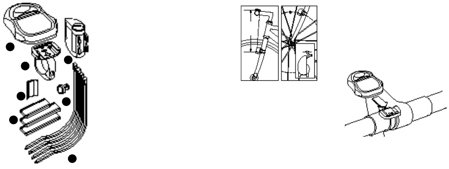
What is included in you SpeedZone® Te a m
p a c k a g e :
1. SpeedZone® Team Computer (1)
2. Mounting bracket (2)
3. Magnet with screw (1)
4. Cable tie wraps (4)
5. Mounting bracket sizing straps (3)
6. Transmitter (1)
7. Transmitter mounting bracket (1)
Mounting the SpeedZone® Te a m :
The SpeedZone® Team Wi reless transmitter can
mount on the right or the left side of the fork blade.
The right side should be used on large frames or
when a suspension fork is installed. The optimal dis-
tance between the computer and the transmitter is 24
inches (610mm) The distance may need to be less that
24 inches (610mm) if ambient temperatures are
below 40 °F (4 °C). To reduce signal loss in colder
t e m p e r a t u r es, the transmitter should be mounted as
close to the computer as possible. (maximum mount-
ing distance is 28 inches). Use the transmitter mount-
ing bracket and tie-wraps provided to position the sen-
s o r. Do not tighten the tie-wraps until final placement
of the magnet is correct. See figure 1.
Attach the magnet to a spoke across fro m
the transmitter with the magnet scre w. The
clearance between the magnet and the
transmitter should be approximately 1 / 3 2 ” -
1/16” (1-2mm). Tighten the magnet and
t r a n s m i t t e r. Do not over-tighten the magnet
s c r ew See figure 2.
Attach the mount to the handlebar using the
bracket screw provided. Tighten so that the
bracket cannot rotate on the handlebar.
T h e re are several sizing straps provided to fit
d i ff e rent diameter bars See figure 3.
the computer forw a rd onto the mounting
until it ‘snaps’ into place with an audible
click. To remove the computer, push it back-
w a r d until it releases from the mount. To test
for proper installation of the magnet, trans-
mitter and computer, activate the computer
by pushing the ‘MODE’ (right side) button
and pick up the front of the bicycle and
spin the wheel. The “wheel option” indica-
tor will flash. If it does not flash, check the
sensor and magnet alignment. Realign as
n e c e s s a ry until the “wheel option” indicator
flashes while spinning the wheel.
1
2
3
4
5
6
7
f i g . 1 f i g . 2
2 4 i n .
m a x
1 - 2 m m
f i g . 3

4 5
P ro g r a m m i n g :
P rogramming the functions of your
SpeedZone® Team re q u i res it to be placed
in various “modes” (i.e. odometer mode,
distance mode). The computer can be
cycled through these modes by pressing the
“MODE” button located on the right-hand
side of the housing. Once a specific mode
has been entered, its values can be reset or
adjusted by pressing either the “FUNC-
TION” button located on the left hand side
of the housing or by using a combination of
the “MODE” and “FUNCTION” buttons.
1. Miles or Kilometers selection:
Your SpeedZone® Team will re c o r d speed
and distance in either miles (M/h) or kilo-
meters (KM/h). To enter your selection of
miles or kilometers, push the “MODE” but-
ton until ODO (odometer) appears in the
lower left side of the display (This is called
the odometer mode). Hold down the
“FUNCTION” (left side) button and ‘tap’ the
“MODE” button once. The Km/h, m/h indi-
cator will begin blinking. You may now
a l t e rnate between miles and kilometers by
p ressing the “MODE” button. When the
c o rrect choice is flashing, select it by pre s s -
ing the “FUNCTION” button. You will now
enter the “Programmable Odometer” mode.
If the odometer setting is correct push the
“FUNCTION” button (5 times) to exit to
odometer mode (otherwise, see “Setting the
p r ogrammable odometer below).
2. Setting the
P ro g r a m m a b l e
O d o m e t e r :
The pro g r a m m a b l e
odometer mode is
accessed by enter-
ing the odometer (ODO) mode and holding
down the “FUNCTION” button and ‘tap-
ping’ the “MODE” button once. The Km/h
indicator will flash. If the Km/h setting is
c o rrect press the “FUNCTION” button once
and a five digit number will appear. Yo u
a r e now in the programmable odometer
mode. This mode is useful if you have
replaced the battery and would like to
retain the mileage you have already rid-
den. To enter a mileage into the odometer,
p ress the “MODE” button until the flashing
digit is correct. (Note: The “MODE” button
may be held to scroll to the correct digit.)
P r ess the “FUNCTION” button to select the
next digit to the right. Repeat the pro c e s s
until all five digits are entered as your exist-
ing mileage.
3. Wheel Circ u m f e r ence Selection:
To set the circ u m f e rence for the type of tire s
you are using, you can use Specialized’s
exclusive “Easy Calibration Mode” or mea-
s u r e your actual tire circ u m f e rence by the
roll-out method. Two diff e r ent tire diameters
may be entered into the computer’s
“Second Wheel Option.”
Easy Calibration Mode:
Your SpeedZone® Team has been pre p ro-
grammed with the following 14
Specialized tire sizes:
•26 X 1.0 •26 X 1.25 •26 X 1.5
•26 X 1.75 •26 X 1.9 •26 X 2.0
•26 X 2.1 •26 X 2.2 •650 X 20
•700c X 20 •700c X 23 •700c X 26
•700c X 32 •700c X 38
When using Easy Calibration Mode, the
SpeedZone® will dis-
play the tire size on
i t ’s LCD display
s c reen. (see figure 6)
The Easy Calibration
Mode is accessed by
entering the odometer (ODO)
mode and holding down the
“FUNCTION” button for three seconds.
The display will now show the curre n t l y
selected tire size for wheel option #1.
To scroll through the pre p rogrammed tire
sizes tap both the “MODE” and “FUNC-
TION” buttons simultaneously. When you
reach the desired tire size press the
“FUNCTION” button once to select it and
enter Easy Calibration Mode for wheel
option #2. Follow the same pro c e d u r e to
p r ogram the wheel #2 tire size and tap the
“FUNCTION” button to exit to odometer
mode.
f i g . 6
6 7
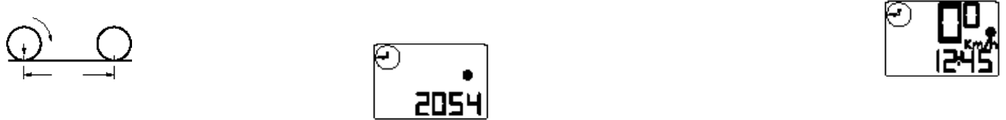
Roll Out Method
The roll out method will provide the most
accurate computer calibration and can take
into account variables such as inflation pre s-
s u r e, rim width and rider weight.
1. Extend a tape measure out to 3000mm
(120 inches) and lock it in place.
2. With your tire inflated to its proper pre s-
s u r e, place the valve at the 6:00 position (at
the bottom) directly over the start of the mea-
suring tape.
3. Roll the wheel one complete revolution until
the valve stem is again at the 6:00 position.
Read the tape directly under the valve and
note the distance in millimeters. (To convert
inches to millimeters, multiply inches by 25.4).
Use this number to replace the default
(default values are 2054 for wheel one, and
2113 for wheel two) when pro g r a m m i n g
your computer.
You may also use
the following
q u i c k
re f e r ence chart :
Generic Ti re Size Chart
This chart is for non-Specialized tire s
26 X 1.75 2 1 4 0
26 X 2.0 2 0 7 4
26 X 2.1 2 0 9 0
650C X 20 1 9 4 5
700C X 26 2 1 2 4
700C X 38 2 1 7 0
P rogramming in the circ u m f e re n c e :
To enter the tire circ u m f e r ence number,
enter the odometer (ODO) mode by hold-
ing down the “FUNCTION” button for
t h ree seconds. The display will now show
the currently selected tire size for wheel
option #1. If necessary scroll through the
p re p r ogrammed tire sizes by tapping both
the “MODE” and “FUNCTION” buttons
simultaneously until the display shows a
four digit number. This number re p re s e n t s
your tire circ u m f e rence in millimeters. Pre s s
the “MODE” button
until the flashing
digit is corre c t .
(Note: The “MODE”
button may be held
to scroll to the correct digit.) Press the
“FUNCTION” button to select the next digit
to the right. Repeat the process until all four
digits are entered as your tire circ u m f e r -
ence. Press the “FUNCTION” button once
to select it and enter the circ u m f e rence for
wheel option #2. Follow the same pro c e-
d u re to program the wheel #2 tire size
and tap the “FUNCTION” button to exit to
odometer mode.
4. Setting the Clock
Your SpeedZone® Team features two
clocks, one analog and one digital. The
hands of the analog clock will be set auto-
matically to correspond to the digital one.
To access the “clock mode” press and hold
the “MODE” button for three seconds. To
set the clock, press the “FUNCTION” but-
ton for three seconds. The display will flash
either twelve (12:) or twenty four (24:).
Select between 12: or 24: mode by pre s s-
ing the “MODE” button. Press the “FUNC-
TION” button to set the mode.
The hour digit will now begin flashing .
P ress the “MODE” button to adjust the hour
digits and press the “FUNCTION” button
to set. The minutes will flash and can be
adjusted by pressing the “MODE” button.
(hold the “MODE” button to scroll thro u g h
the digits quickly) Press the “FUNCTION”
button to set the minutes and re t u rn to clock
m o d e
N o t e : The minute-hand of the analog
clock has twelve segments and can only
display time in five minute increments. The
hand will not jump to the next segment
until the digital clock reaches whole five
minute intervals. (e.g. 12:05, 12:10,
12:15 etc.)
5. Ti m e r
S e l e c t i o n
The timer can be
selected for either
Automatic Ti m e r
Mode (ATM) or
Timer Mode (TM). The ATM selection
Roll Forw a r d
S t e m
Wheel
C i rc u m f e re n c e
8 9
allows you to keep track of your actual rid-
ing time. The timer
only operates w h e n
the wheel is ro t a t i n g
and cannot be
t u rned on or off man-
u a l l y.
The TM selection is just like a conventional
stopwatch. The timer is activated manually
and re c o r ds the time whether the wheel is
rotating or not. Tapping the “FUNCTION”
button starts and stops the stopwatch and
holding the “FUNCTION” button for thre e
seconds will reset to stopwatch.
N o t e : The average speed (AVS) will be
calculated diff e rently based upon the selec-
tion of ATM or TM. If ATM is selected,
the AVS is based upon only riding time.
If TM is selected the AVS is based on the
total time the stopwatch is turned on or
activated.
To select between ATM and TM press and
hold the “FUNCTION” and tap the
“MODE” button. Either ATM or TM will
flash. Press the “MODE” button to select
between the two modes and press “FUNC-
TION” to re t u r n to normal operating mode.
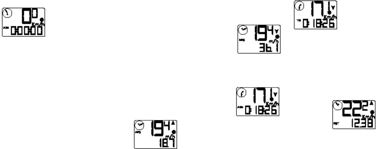
Computer Functions
S p e e d o m e t e r - Speed is always indicated
on the top line of the screen. The speed is
shown continuously up to 99.9M/h (99.9
Km/h) with a resolution of 0.1 M/h (0.1
K m / h )
Average Speed (AVS)- The average
speed is displayed on the lower line of the
s c r een when AVS is shown on the left. The
average speed is based upon whether the
ATM or the TM mode has been selected,
the resolution of the average speed is
shown in 0.1M/h or Km/h incre m e n t s .
+/- Average Speed Indicator- An up
or down arro w
displayed in the
upper right side of
the screen shows
whether the cur-
rent speed is above or below the average
speed. The arrow is always displayed so
you know if you’re maintaining your aver-
age speed while in another mode.
M a x i m u m
Speed (MXS)-
The maximum is
displayed on the
lower line of the
s c r een when MXS is shown on the left. The
maximum speed is retained in memory and
updated when a higher speed is attained.
The maximum speed can be reset by pre s s-
ing the “FUNCTION” button for three sec-
o n d s .
A u t o
S t a rt / S t o p
Timer (AT M ) -
The stop watch
function will operate only when there is
speed input and re c o rds the actual time
spent riding. Pressing the “FUNCTION” key
for 3 seconds will reset the ATM display to
z e ro .
Timer Mode
( T M ) - In TM mode
the stopwatch func-
tion will operate when the “FUNCTION”
button is pressed. The stopwatch will re c o r d
the total time after the button is pre s s e d
re g a rdless of whether there is speed input or
not. The average speed (AVS) will be calculat-
ed based on the time the timer mode is acti-
v a t e d .
Trip Distance (DST)- Trip distance mode
will re c o r d up to 999.99 miles or kilometers
and then roll to zero. The trip distance func-
tion can be re s e t
by pressing the
“FUNCTION” but-
ton for three sec-
onds. The re s o l u-
tion is 0.01 miles
(0.01Kilometers). The trip distance is shown
on the lower line of the scre e n .
10 11
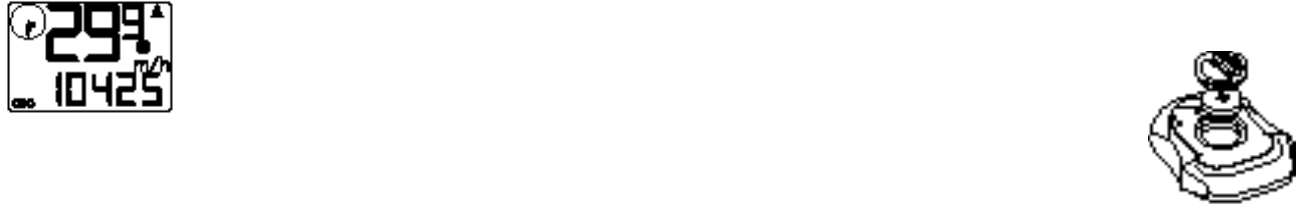
Odometer (ODO)- The odometer will
re c o r d the total distance traveled up to
99,999 miles or kilometers and then roll to
z e ro. The odometer can be reset by pre s s-
ing the “FUNC-
TION” button for
t h r ee seconds.
The total distance
is shown on the
lower line of the
s c re e n .
P rogrammable Odometer- T h e
odometer digits are user setable. This is
convenient for transferring your hard - e a rn e d
mileage that is usually lost when changing
batteries or computers.
Clock- The SpeedZone® Team has two
clocks, one digital and one analog. The
digital clock is accessed by pressing the
“MODE” button for three seconds. There is
an option of either 12 hour or 24 hour
clock settings and is shown on the lower
line of the screen. The analog clock is
always displayed in the upper right side of
the screen. The minute-hand of the analog
clock has twelve segments and can only
display time in five minute increments. The
hand will not jump to the next segment until
the digital clock reaches whole five minute
i n t e rv a l s .
Second Wheel Mode- For riders who
own more than one bicycle or who fre-
quently change tires, the SpeedZone®
Team is capable of storing two tire sizes.
You can change between the two sized by
p ressing both the “MODE” and “FUNC-
TION” buttons simultaneously for three sec-
onds. The second wheel mode indicator
will change from 1 to 2. Mileage re c o rd e d
will be cumulative between the two sizes.
(an accessory handlebar mount is available
f rom your Specialized dealer)
Backlight- The backlight feature of your
SpeedZone® Team is activated by pre s s i n g
the “BACKLIGHT” button on the top of the
c o m p u t e r. When pressed the backlight will
remain on for 5 seconds. During this time
the current-speed display will be fro z e n ,
however the SpeedZone® Team will con-
tinue to monitor time and distance functions.
Triple Display LCD- The display scre e n
on your SpeedZone® Team can pro v i d e
t h ree pieces of information simultaneously:
C u rrent Speed (always displayed on the top
line of the screen), Current Time (on analog
clock),and your choice of one of the follow-
ing: Average Speed, Maximum Speed,
C u rrent Time (digital clock), Trip Distance or
O d o m e t e r.
Installing the Battery -
Your SpeedZone® Team Computer comes
with the battery installed at the factory.
Should you need to replace the battery,
push the computer backwards to remove it
f rom the handlebar mount. Before re m o v i n g
the battery make a note of your odometer
reading and wheel circ u m f e r ence settings
so that you can re-enter them when you
re s t a rt the computer. Tu rn the computer over
so the display is facing downward. Use a
coin to unthread the battery cap from the
c o m p u t e r. Install the battery (model
CR2032) with the positive pole (+) facing
u p w a r d. Carefully thread the battery cap
back onto the case with a coin.
(See Figure 7)
If the LCD display is
blank or shows
incomplete digits, turn
the computer over
and press the “AC”
button on the bottom
of the case with the
tip of a pen or a paper clip. This will clear
all the data and re - s t a rt the computer.
Reinstall the computer by pushing it forw a rd
into the mount until it snaps into place.
The Transmitter battery can be replaced by
using a small coin to unthread the battery
cap from the transmitter, replacing the bat-
t e ry (model 23A) and carefully thre a d i n g
the battery cap back into place.
f i g . 7
12 13
Troubleshooting:
Display is blank: Change the battery
or press the AC button on the bottom of
the case
Display shows partial digits: Press
the AC button on the bottom of the case.
Speed/distance not recording:
Check transmitter/magnet alignment.
Make sure that the transmitter is no more
than 28 inches from the battery (move
the transmitter as close to the computer
as possible).l
Entire screen is dark: Did you leave
the bike parked in the hot direct sun
when it was parked? If so, move the bike
to the shade. The data will be OK.
Computer moves on handlebar:
Tighten mount or add sizing straps to
improve fit on handlebar.
Important!
Pay attention to traffic and road condi-
tions at all times. Your first obligation is
to be attentive and to ride safely.
• Keep your computer in good shape
and use it safely:
• Do not expose it to direct sunlight
except when you are riding
• Do not disassemble it
• Make sure the magnet and the
transmitter are well aligned. Check them
re g u l a r l y.
• Keep the computer and all of its com-
ponents tightly attached, and check them
regularly. If any of the components come
loose, it could become tangled in your
spokes and cause an accident.
• See your authorized Specialized deal-
er if you have any trouble installing or
maintaining your computer.
• Clean the unit with a mild detergent
and a soft dry cloth. Never use any kind
of solvent or alcohol.
• The SpeedZone® Team computer is
intended for use on bicycles only and
should not be used on any motorized
vehicle.
Wa rranty Inform a t i o n :
Specialized cycling computers are guaran-
teed to be free from defects in materials
and/or workmanship (excluding battery) for
a period of two years from the date of pur-
chase. Specialized will at its option, re p a i r
or replace your defective computer.
To receive warranty service send the unit, a
copy of the sales receipt and a brief
description of the problem to:
Specialized Bicycle Components Inc.
15130 Concord Circ l e
M o rgan Hill, CA. 95037
Attn: Product Serv i c e s / C o m p u t e r
Wa rr a n t y
S p e c i f i c a t i o n s :
C u rrent Speed: 0.0 to 99.9 MPH
0.0 to 99.9 Km/H
Average Speed 0.0 to 199.9 MPH
( AV S ) 0.0 to 199.9 Km/H
Maximum Speed 0.0 to 199.9 MPH
( M X S ) 0.0 to 199.9Km/H
Stopwatch 0 to 9hrs, 59min,
( T M ) 59sec. recycling type
Automatic Ti m e r 0 to 9hrs, 59min, )
( AT M ) 59sec. recycling type
Trip Distance 0 to 999.99 miles or Km
( D S T )
Odometer 0 to 99,999 miles or Km
( O D O )
Operating Temp 40°F to 104°F
(4°C to 40°C)
