Spectra Dg711 Users Manual DG711and511_CI_12810104_0502_JP
DG711 to the manual 50c31c45-7265-4815-86fd-f6837792c733
2015-02-06
: Spectra Spectra-Dg711-Users-Manual-528188 spectra-dg711-users-manual-528188 spectra pdf
Open the PDF directly: View PDF ![]() .
.
Page Count: 96
- DG711-511_160C_UserGuide_ENG.pdf
- DG711 and DG511 Pipe Laser
- Introduction
- Features and Functions
- Preparation Before Operation
- Getting Started
- Applications and Setups
- Grade
- Elevation
- Line
- Setup, Step-by- Step
- Set Grade
- Set Elevation for Small In-the-Pipe or Pre-cast Inverts
- Elevation of Flat Bottom Manholes
- 1230/1237 Heavy Duty Invert Plate
- 1239 Universal Fixed Pole
- Setting Line
- First Point Setup (Using Plumb-bob)
- 1211 Laser Plummet Line Setting
- Second Far-Point Alignment
- Setting Line with the Line Set/Check Featu re
- Activating the Cross Axis Roll Option
- Activating Line Set/Check Raise
- Activating Line Set/Check Lower
- Large Pipe
- In a Manhole
- Open Excavations
- Over the Top
- DG511/711 Additional Accessories
- Refraction
- DG511/711 Troubleshooting
- Calibration
- Maintenance and Care
- Laser Specifications
- DG711 and DG511 Pipe Laser
F
Version 1.6
Part Number 1281-0100
Revision C
September 2007
DG711 and DG511
Pipe Laser
User Guide
Corporate Office
Trimble Construction Division
5475 Kellenburger Road
Dayton, Ohio 45424-1099
U.S.A.
(800) 538-7800 (Toll Free in U.S.A.)
+1-937-245-5600 Phone
+1-937-233-9004 Fax
www.trimble.com
Copyright and Trademarks
© 2002-2007, Trimble Navigation
Limited. All rights reserved.
The Globe & Triangle logo, and
Trimble are trademarks of Trimble
Navigation Limited.
All other trademarks are the property
of their respective owners.
Release Notice
This is the September 2007 release
(Revision C) of the DG711 and DG511
Pipe Laser User Guide, part number
1281-0100. It applies to version 1.6 of
the DG711 and DG511 Pipe Laser
software.
The following limited warranties give
you specific legal rights. You may have
others, which vary from
state/jurisdiction to state/jurisdiction.
Hardware Limited Warranty
Trimble Navigation Limited warrants
that this hardware product (the
“Product”) will perform substantially
in accordance with published
specifications and be substantially free
of defects in material and
workmanship for a period of one (1)
year (DG511 Pipe Laser) and two (2)
years (DG711 Pipe Laser) starting
from the date of delivery. The warranty
set forth in this paragraph shall not
apply to software products.
Software License, Limited
Warranty
This Trimble software product,
whether provided as a stand-alone
computer software product, built into
hardware circuitry as firmware,
embedded in flash memory, or stored
on magnetic or other media, (the
“Software”) is licensed and not sold,
and its use is governed by the terms of
the relevant End User License
Agreement (“EULA”) included with
the Software. In the absence of a
separate EULA included with the
Software providing different limited
warranty terms, exclusions and
limitations, the following terms and
conditions shall apply. Trimble
warrants that this Trimble Software
product will substantially conform to
Trimble’s applicable published
specifications for the Software for a
period of ninety (90) days, starting
from the date of delivery.
Warranty Remedies
Trimble's sole liability and your
exclusive remedy under the warranties
set forth above shall be, at Trimble’s
option, to repair or replace any Product
or Software that fails to conform to
such warranty ("Nonconforming
Product") or refund the purchase price
paid by you for any such
Nonconforming Product, upon your
return of any Nonconforming Product
to Trimble in accordance with
Trimble’s standard return material
authorization procedures.
Warranty Exclusions and
Disclaimer
These warranties shall be applied only
in the event and to the extent that the
Products and Software are properly
and correctly installed, configured,
interfaced, maintained, stored, and
operated in accordance with Trimble's
relevant operator's manual and
specifications, and; (ii) the Products
and Software are not modified or
misused. The preceding warranties
shall not apply to, and Trimble shall
not be responsible for defects or
performance problems resulting from
(i) the combination or utilization of the
Product or Software with hardware or
software products, information, data,
systems, interfacing or devices not made,
supplied or specified by Trimble; (ii) the
operation of the Product or Software under
any specification other than, or in addition
to, Trimble's standard specifications for its
products; (iii) the unauthorized
modification or use of the Product or
Software; (iv) damage caused by accident,
lightning or other electrical discharge,
fresh or salt water immersion or spray; or
(v) normal wear and tear on consumable
parts (e.g., batteries). Trimble does not
warrant or guarantee the results obtained
through the use of the Product.
THE WARRANTIES ABOVE STATE
TRIMBLE'S ENTIRE LIABILITY, AND
YOUR EXCLUSIVE REMEDIES,
RELATING TO PERFORMANCE OF THE
PRODUCTS AND SOFTWARE. EXCEPT AS
OTHERWISE EXPRESSLY PROVIDED
HEREIN, THE PRODUCTS, SOFTWARE,
AND ACCOMPANYING
DOCUMENTATION AND MATERIALS
ARE PROVIDED “AS-IS” AND WITHOUT
EXPRESS OR IMPLIED WARRANTY OF
ANY KIND BY EITHER TRIMBLE
NAVIGATION LIMITED OR ANYONE
WHO HAS BEEN INVOLVED IN ITS
CREATION, PRODUCTION,
INSTALLATION, OR DISTRIBUTION
INCLUDING, BUT NOT LIMITED TO, THE
IMPLIED WARRANTIES OF
MERCHANTABILITY AND FITNESS FOR
A PARTICULAR PURPOSE, TITLE, AND
NONINFRINGEMENT. THE STATED
EXPRESS WARRANTIES ARE IN LIEU
OF ALL OBLIGATIONS OR
LIABILITIES ON THE PART OF
TRIMBLE ARISING OUT OF, OR IN
CONNECTION WITH, ANY
PRODUCTS OR SOFTWARE. SOME
STATES AND JURISDICTIONS DO
NOT ALLOW LIMITATIONS ON
DURATION OR THE EXCLUSION OF
AN IMPLIED WARRANTY, SO THE
ABOVE LIMITATION MAY NOT
APPLY TO YOU.
TRIMBLE NAVIGATION LIMITED IS
NOT RESPONSIBLE FOR THE
OPERATION OR FAILURE OF
OPERATION OF GPS SATELLITES OR
THE AVAILABILITY OF GPS
SATELLITE SIGNALS.
Limitation of Liability
TRIMBLE’S ENTIRE LIABILITY UNDER
ANY PROVISION HEREIN SHALL BE
LIMITED TO THE AMOUNT PAID BY YOU
FOR THE PRODUCT OR SOFTWARE
LICENSE. TO THE MAXIMUM EXTENT
PERMITTED BY APPLICABLE LAW, IN
NO EVENT SHALL TRIMBLE OR ITS
SUPPLIERS BE LIABLE FOR ANY
INDIRECT, SPECIAL, INCIDENTAL OR
CONSEQUENTIAL DAMAGES
WHATSOEVER UNDER ANY
CIRCUMSTANCE OR LEGAL THEORY
RELATING IN ANY WAY TO THE
PRODUCTS, SOFTWARE AND
ACCOMPANYING DOCUMENTATION
AND MATERIALS, (INCLUDING,
WITHOUT LIMITATION, DAMAGES FOR
LOSS OF BUSINESS PROFITS, BUSINESS
INTERRUPTION, LOSS OF BUSINESS
INFORMATION, OR ANY OTHER
PECUNIARY LOSS), REGARDLESS
WHETHER TRIMBLE HAS BEEN
ADVISED OF THE POSSIBILITY OF ANY
SUCH LOSS AND REGARDLESS OF THE
COURSE OF DEALING WHICH DEVELOPS
OR HAS DEVELOPED BETWEEN YOU
AND TRIMBLE. BECAUSE SOME STATES
AND JURISDICTIONS DO NOT ALLOW
THE EXCLUSION OR LIMITATION OF
LIABILITY FOR CONSEQUENTIAL OR
INCIDENTAL DAMAGES, THE ABOVE
LIMITATION MAY NOT APPLY TO YOU.
NOT WITHSTANDING THE ABOVE, IF
YOU PURCHASED THIS PRODUCT OR
SOFTWARE IN THE EUROPEAN
UNION, THE ABOVE WARRANTY
PROVISIONS MAY NOT APPLY.
PLEASE CONTACT YOUR DEALER
FOR APPLICABLE WARRANTY
INFORMATION.

Notices
FCC Decleration of Confirmity
Class A Statement – Notice to Users.
This equipment has been tested and
found to comply with the limits for a
Class A digital device, pursuant to Part
15 of the Federal Communication
Commission (FCC) rules. These limits
are designed to provide reasonable
protection against harmful interference
in a commercial environment. This
equipment generates, uses, and can
radiate radio frequency energy and, if
not installed and used in accordance
with the instructions, may cause
harmful interference to radio or
television communication. However,
there is no guarantee that interference
will not occur in a particular
installation. If this equipment does
cause harmful interference to radio or
television reception, which can be
determined by turning the equipment
off and on, the user is encouraged to try
to correct the interference by one or
more of the following measures:
– Reorient or relocate the receiving
antenna.
– Increase the separation between the
equipment and the receiver.
– Connect the equipment into an
outlet on a circuit different from that
to which the receiver is connected.
– Consult the dealer or an experienced
radio/TV technician for help.
Changes and modifications not
expressly approved by the
manufacturer or registrant of this
equipment can void your authority to
operate this equipment under Federal
Communications Commission rules.
Canadian regulatory notice
The digital apparatus does not exceed
the Class AA limits for radio noise for
digital apparatus set out in the Radio
Interference Regulation of the
Canadian Department of
Communications.
EEC regulatory notice
Notice to Our European Union Customers
For product recycling instructions and more information,
please go to: www.trimble.com/environment/summary.html
Recycling in Europe
To recycle Trimble WEEE,
call: +31 497 53 2430, and
ask for the "WEEE associate," or
mail a request for recycling instructions to:
Trimble Europe BV
c/o Menlo Worldwide Logistics
Meerheide 45
5521 DZ Eersel, NL
Application of
Council Directive(s)
89/336/EEC
Manufacturer’s name Trimble Navigation
Limited
Manufacturer’s
address
5475 Kellenburger Road
Dayton, Ohio
45424-1099, U.S.A.
European
representative
address
Tr i mb le Gm bH
Am Prime Parc 11
65479 Raunheim,
Germany
Model number(s) DG711 and DG511
Conformance to
directive(s)
EC Directive 89/336/EEC
using EN55022 and
EN50082-1
Equipment
type/environment
ITE/residential,
commercial and light
industrial
Product standards Product meets the limit B
and methods of EN55022
Product meets the levels
and methods of
IEC 801-2, 8 kV air, 4 kV
contact
IEC 801-3, 3 V/m 26 to
1000 MHz 80%, @ 1 kHz
IEC 801-4, ac leads 2 kV

Safety Information
For detailed installation and operating instructions, follow the instructions
given in this manual for this laser.
Laser Safety 0.0.1
The maximum radiant power
output of this laser is less than
5 mW. Use only the targets
supplied with this product.
Controls are listed on the radiation
control drawings.
CWarning – Use of controls
or adjustments
performance of
procedures other than
those specified may result
in higher dosage of laser
exposure.
To help you comply with your
government regulations, a laser
safety kit is supplied with every
laser. This kit contains operator
qualification cards and a sign that
should be posted near the laser
whenever it is in use.
As with any visible laser device,
observe the following safety rules:
• Never look directly into a laser
beam or point the beam into the
eyes of others. Set the laser at a
height that prevents the beam from
shining directly into people’s eyes.
• Do not remove any warning
signs from the laser.
• Make sure that only properly
trained people use this product.
• If service is required, which
results in the removal of the outer
protective cover, factory-trained
personnel must perform this.
Certification 0.0.2
The IEC and the United States
Government Center of Devices for
Radiology Health (CDRH) has
classified this laser as a Class
3R/3A laser product. This laser
complies with IEC/EN
60825-1:2001, CDRH 21 CFR
1040.10 and 1040.11.
Queries 0.0.3
Address any questions you may
have about laser safety to:
Trimble
5475 Kellenburger Road
Dayton, Ohio 45424-1099
U.S.A.
Attention: Quality Assurance
Group, Laser Safety Officer
Phone (937) 233-8921 ext 824 or
(800) 538-7800
Fax (937) 233-9661
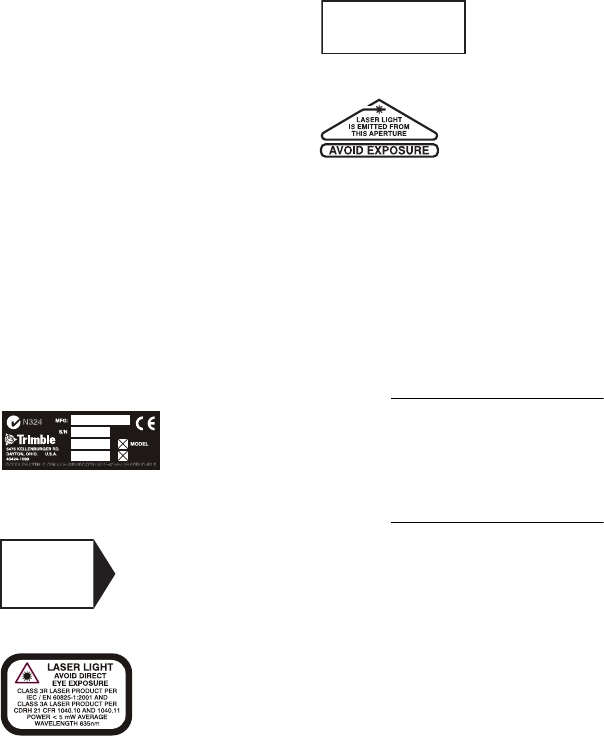
Labels 0.0.4
The labels required for this product
are:
Certification and Identification:
Non-Interlocked Protective
Housing:
Danger Logotype:
Battery:
Aperture:
Warning and
Cautions 0.0.5
Warnings and Notes in the text
indicate a level of danger or
concern. Ensure that you follow the
instructions that accompany these
alerts:
CWarning – A Warning
indicates a hazard or an
unsafe practice that could
result in minor injury or
property damage.
Note – A Note indicates important
information unrelated to safety.
DANGER
LASER LIGHT
WHEN OPEN.
AVOID DIRECT
EYE EXPOSURE
DO NOT OPEN
NON-REPLACEABLE BATTERIES
CHARGING TEMPERATURE
RANGE 0˚C TO 25˚C
DG711 and DG511 Pipe Laser User Guide i
Contents
1 Introduction
Claim for Damage in Shipment . . . . . . . . . . . . . . 6
Owner’s Record . . . . . . . . . . . . . . . . . . . . . . 6
2 Features and Functions
Laser . . . . . . . . . . . . . . . . . . . . . . . . . . . . 7
Remote Controls . . . . . . . . . . . . . . . . . . . . . 10
Model RC501, 3-Button Remote Control . . . . 10
Model RC502, 7-Button Remote Control . . . . 11
3 Preparation Before Operation
Powering the Laser. . . . . . . . . . . . . . . . . . . . 13
Ni-MH Batteries . . . . . . . . . . . . . . . . . 13
External Power Cable P21 . . . . . . . . . . . . 16
Optional Features . . . . . . . . . . . . . . . . . . . . 18
4 Getting Started
Optional Features Operating Instructions . . . . . . . . 24
5 Applications and Setups
Grade . . . . . . . . . . . . . . . . . . . . . . . . . . . 30
Elevation . . . . . . . . . . . . . . . . . . . . . . . . . 30
Line. . . . . . . . . . . . . . . . . . . . . . . . . . . . 31
Setup, Step-by-Step . . . . . . . . . . . . . . . . . . . 31
Set Grade . . . . . . . . . . . . . . . . . . . . . 31
Set Elevation for Small In-the-Pipe or
Pre-cast Inverts . . . . . . . . . . . . . . . . 32
Elevation of Flat Bottom Manholes . . . . . . . 34

Contents
ii DG711 and DG511 Pipe Laser User Guide
1230/1237 Heavy Duty Invert Plate . . . . . . . 34
1239 Universal Fixed Pole . . . . . . . . . . . . 35
Setting Line . . . . . . . . . . . . . . . . . . . . 41
First Point Setup (Using Plumb-bob). . . . . . . 41
1211 Laser Plummet Line Setting . . . . . . . . 43
Second Far-Point Alignment . . . . . . . . . . . 43
Setting Line with the Line Set/Check Feature . . 44
Activating the Cross Axis Roll Option . . . . . . 44
Activating Line Set/Check Raise . . . . . . . . . 45
Activating Line Set/Check Lower . . . . . . . . 46
Large Pipe . . . . . . . . . . . . . . . . . . . . 47
In a Manhole . . . . . . . . . . . . . . . . . . . 48
Open Excavations. . . . . . . . . . . . . . . . . 51
Over the Top . . . . . . . . . . . . . . . . . . . 52
6 DG511/711 Additional Accessories
1211 Laser Plummet . . . . . . . . . . . . . . . . . . . 55
1238/1249 Mounting Plates . . . . . . . . . . . . . . . 56
1244 and 1244-1 T-Bars . . . . . . . . . . . . . . . . . 56
Features . . . . . . . . . . . . . . . . . . . . . . 57
Setup Instructions. . . . . . . . . . . . . . . . . 59
Pipe Targets . . . . . . . . . . . . . . . . . . . . . . . 60
Through the Pipe Applications . . . . . . . . . . 60
Over the Top Applications . . . . . . . . . . . . 61
Model 936 Adjustable Pipe Target . . . . . . . . 62
Model 956 Optically Enhanced Universal Target 63
Model 1212 LineLevel . . . . . . . . . . . . . . 63
1232 Precast Invert Adapter . . . . . . . . . . . 64
Model 1214 Line String Adapter . . . . . . . . . 65

Contents
DG711 and DG511 Pipe Laser User Guide iii
7Refraction
Model 929 Blower Operating Instructions . . . . . . . . 69
8 DG511/711 Troubleshooting
9 Calibration
Checking the Calibration. . . . . . . . . . . . . . . . . 75
Adjusting the Calibration . . . . . . . . . . . . . . . . 77
Grade Check . . . . . . . . . . . . . . . . . . . . . . . 78
Example. . . . . . . . . . . . . . . . . . . . . . 79
10 Maintenance and Care
Storage . . . . . . . . . . . . . . . . . . . . . . . . . . 81
Battery Disposal . . . . . . . . . . . . . . . . . . . . . 82
System Cleaning . . . . . . . . . . . . . . . . . . . . . 82
11 Laser Specifications
Request for Service and Parts . . . . . . . . . . . . . . 86

Contents
iv DG711 and DG511 Pipe Laser User Guide

DG711 and DG511 Pipe Laser User Guide 5
CHAPTER
1
Introduction 1
Thank you for choosing from the
Trimble family of precision pipe
lasers. You’ve just made a wise
investment in field-proven products
made by Trimble, the world’s
leading manufacturer of laser-
based leveling, alignment, and
grade-control systems.
The pipe laser is an easy-to-use
tool that provides underground
contractors line, elevation, and
grade control for installing storm,
sanitary, or other gravity-flow pipe.
This system can also be used for
tunneling, boring, pipe alignment,
or any other application requiring
line, elevation, and grade control.
The pipe laser projects a highly
visible red beam of laser light in a
direction at a predetermined
(grade) for the alignment of
gravity-flow pipe. The laser light is
intercepted by a target. To align the
pipe, you need to position it so that
the pipe laser’s beam is centered in
the target.

1 Introduction
6 DG711 and DG511 Pipe Laser User Guide
Included in this manual is
information about setting up,
using, maintaining, and
troubleshooting the laser system.
Use the manual now to learn basic
skills, and use it later for reference.
For the best performance of your
laser system, follow the
maintenance and care
recommendations in this manual.
Be sure to keep this manual in a
convenient place for easy
referencing.
Your comments and suggestions
are welcome; please call the
Trimble Construction Division
listed below for your local,
authorized Trimble office.
Trimble Construction Division
5475 Kellenburger Road
Dayton, Ohio 45424-1099
U.S.A.
Phone: (937) 245-5600
(800) 538-7800
Fax: (937) 233-9004
www.trimble.com
Claim for Damage
in Shipment 1.1
The pipe laser system generally
includes a pipe laser, remote
control, laser target, optional
external power cable, operator’s
manual, laser safety kit, carrying
case, rechargeable batteries, and
battery recharger. The components
vary depending on the system that
you purchase.
You should inspect your pipe laser
system as soon as you receive it. It
has been packaged for safe
delivery. If it is damaged in any
way, immediately file a claim with
the carrier or, if insured separately,
with the insurance company.
Owner’s Record 1.2
Be sure to record the serial number
of each component in the space
provided below. Refer to these
numbers if you need to contact
your Trimble dealer regarding any
of these products.
Serial Number________________
Model # ________________
DG711 and DG511 Pipe Laser User Guide 7
CHAPTER
2
Features and
Functions 2
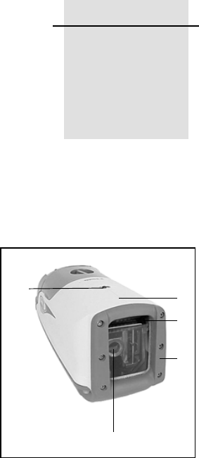
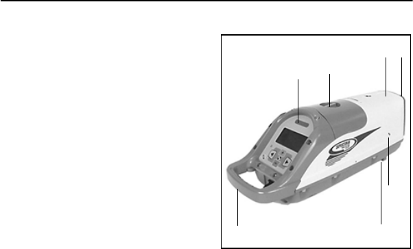
Laser 2.1
1Beam-Exit Window – provides
a clear window for the laser beam
to exit the pipe laser.
2Front and Rear Remote
Receiver Window – receives
signals from models RC501 and
RC502 Remote Control to perform
various keypad functions.
3Line-Axis Pivot Marker and
LED – identifies the pivot point for
the pipe laser’s line system. The
LED lights for 15 minutes after
turning on the pipe laser or
pressing a control-panel button.
The LED also allows you to align a
transit over the top of the pipe
laser.
4Alignment Markers –
correspond with the line system of
the pipe laser. Use them with the
Line Center feature to align the
laser with a distant control point.
1
2
4
3
20
2 Features and Functions
8 DG711 and DG511 Pipe Laser User Guide
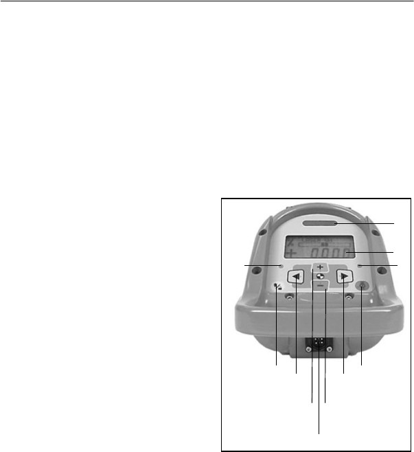
5Liquid Crystal Display (LCD)
– shows the power, grade, battery,
out-of-level, line position, and
status of the pipe laser.
6Backlight/Lock Button –
activates the LCD’s backlight and
line-pivot LED. If you
simultaneously press this button
along with one of the line control
or grade buttons, it locks/unlocks
the control panel, so that the grade
and line system are not
unintentionally changed.
7Power Button – turns the pipe
laser on/off. Press and hold the
button for about 2 seconds to turn
the unit off.
8Left Line-Control Button –
moves the laser beam to the left1.
To center the line, this button has to
be pressed simultaneously with the
right line.
9Right Line-Control Button –
moves the laser beam to the right1.
To center the line, this button has to
be pressed simultaneously with the
left line.
10 Negative Grade LED – lights
red to show that you have entered a
negative grade into the pipe laser.
11 Positive Grade LED – lights
green to show that you have
entered a positive grade into the
pipe laser.
12 Increase Button – increases the
grade.1 To zero the grade and
change the grade in quick change
mode, press and hold this button
simultaneously with the decrease
button.
13 Decrease Button – decreases
the grade1. To zero the grade and
change the grade in quick change
mode, press and hold this button
simultaneously with the increase
button.
1. Use this button in combination with others for further operations.
5
7
8 9
6
10 11
12 13
14
2
Features and Functions 2
DG711 and DG511 Pipe Laser User Guide 9
14 External Power Receptacle –
allows the pipe laser to be powered
by an optional external 6–16 VDC
power source.
15 5/8-11 Threaded Mount –
allows the pipe laser to be attached
to various setup accessories.
16 Grade-Axis Pivot Marker –
identifies the pivot point for the
pipe laser’s grade system.
17 Battery Pack – contains non-
replaceable Ni-MH batteries, or a
pack that can hold four replaceable
D-Cell alkaline batteries to power
the pipe laser (depending on
model).
18 Handle – allows you to carry
the pipe laser easily and provides a
safety-rope tie-off.
19 Armor Plated Housing – plated
with a special, hardened military
material for unsurpassed
ruggedness and reliability.
20 Protective Rubber Bumper –
protects the front end of the unit by
safeguarding the exit window.
16
18
17
15
19
2
20
2 Features and Functions
10 DG711 and DG511 Pipe Laser User Guide
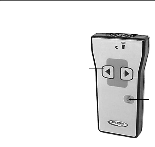
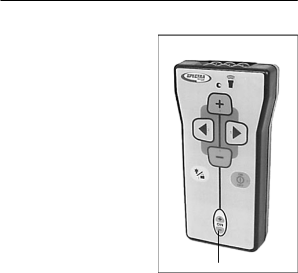
Remote Controls 2.2
Model RC501, 3-Button
Remote Control 2.2.1
1Power – turns the pipe laser
on/off. Press and hold the button
for about 2 seconds to turn the unit
off.
2Left Line-Control Button –
allows you to move the laser beam
to the left.
3Right Line-Control Button –
allows you to move the laser beam
to the right.
Note – Line Center – Press Left
Line-control and Right
Line-Control simultaneously to
center the line.
4Status LED - flashes four times
per second when a line button is
pressed or once per second to
indicate that the internal battery is
low.
5Emission Window – provides
an opening for the infrared signals
to exit from so that the remote
control and pipe laser can
communicate with each other.
2
3
4
1
5
Features and Functions 2
DG711 and DG511 Pipe Laser User Guide 11
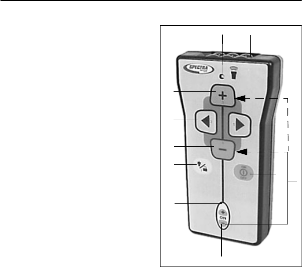
Model RC502, 7-Button
Remote Control 2.2.2
1Power – turns the pipe laser
on/off. Press and hold the button
for about 2 seconds to turn the unit
off.
2Grade-Enable LED – flashes
when the grade-enable function is
activated.
3Grade-Enable Button –
activates/deactivates the increase
and decrease button. Deactivating
the grade-enable function prevents
the pipe laser grade value from
accidentally being changed.
4Backlight/Lock Button –
activates the pipe-laser LCD’s
backlight. If this button is pressed
simultaneously with one of the line
control or grade buttons, it
locks/unlocks the control panel so
that the line and grade system do
not get accidentally changed.
5Decrease Button – allows you
to decrease the grade.
6Left Line-Control Button –
allows you to move the laser beam
to the left.
7Increase Button – allows you to
increase the grade.
8Status LED – flashes four times
per second when a control button is
pressed or once per second to
indicate that the internal battery is
low.
9Right Line-Control Button –
allows you to move the laser beam
to the right.
10 Emission Window – provides
an opening for the infrared signals
to exit from so that the remote
1
4
5
69
8
7
3
2
10
11

2 Features and Functions
12 DG711 and DG511 Pipe Laser User Guide
control and pipe laser can
communicate with each other.
11 Grade Bump – If the Grade
Enable button and either Grade
button are pressed simultaneously,
the grade changes by one
increment. This function enables
small grade changes for matching
to existing grade.
DG711 and DG511 Pipe Laser User Guide 13
CHAPTER
3
Preparation
Before
Operation 3
Powering the
Laser 3.1
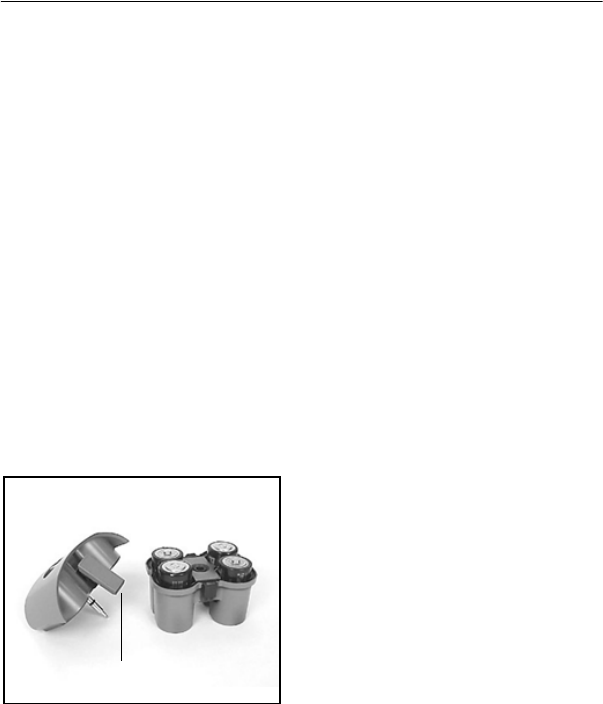
Ni-MH Batteries 3.1.1
Installing/Removing the
batteries
1Turn the battery-pack knob
counterclockwise. Lift the battery
pack from the pipe laser.
2Plug the battery-pack in place
and turn the battery knob
clockwise.
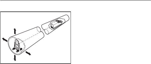
Optional Alkaline Battery
Pack
1Turn the battery-pack knob
counterclockwise. Lift the battery
pack from the pipe laser.
2Pull out on the top of the side
clips then push down on them to
release them from the side-clip
catches.
3 Preparation Before Operation
14 DG711 and DG511 Pipe Laser User Guide
3Pull on the top housing to
separate it from the bottom
housing. Make sure to detach
latches from bottom housing.
4Install/remove the batteries.
Note – When installing the
batteries, ensure that you take note
of the positive (+) and negative (-)
diagram inside of the housing.
Note – The pipe laser has reverse
polarity protection. If the batteries
are put in wrong, no damage
occurs to the pipe laser but it does
not work. Allow it one minute to
recover after the batteries have
been installed correctly.
5Put the top housing back on the
bottom housing.
6Position the side clips so that
they hold the top and bottom
housings together securely.
7Put the battery pack in place
and turn the battery-pack knob
clockwise.
6
Preparation Before Operation 3
DG711 and DG511 Pipe Laser User Guide 15
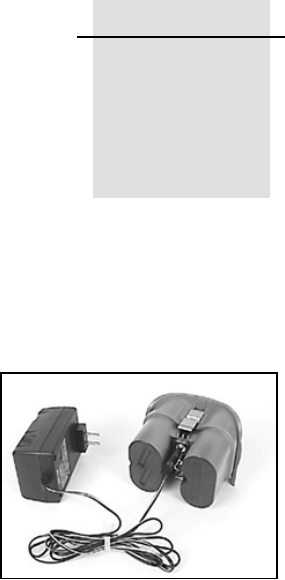
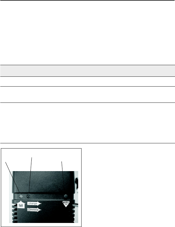
Smart Charger
The charger, to be used ONLY with the Ni-MH battery pack, starts
charging automatically as soon as a battery pack is installed and the charger
is plugged in. The LEDs on the charger indicate the condition shown in
Table 3.1.
Discharge Button: Pressing the
button for approximately 2 seconds
the charger automatically
discharges the battery and switches
over to charging. The process of
discharging the battery before
charging should be performed
every three months to help prevent
loss of battery capacity due to
frequent partly discharging.
Table 3.1 LED condition
LED condition Description
Red LED On Batteries are charging
Green LED on Batteries are fully charged, and the charger has
switched to trickle charge
Flashing red LED Battery-contact detection (test phase)
Battery-pack reversed
Battery pack broken, open or unsuitable cells
The batteries are discharging after pressing the
discharge button
Green LED
Red LED Discharge
Button

3 Preparation Before Operation
16 DG711 and DG511 Pipe Laser User Guide
Charging Time:
Table 3.2 shows the approximate charging time for 4 to10 batteries with a
7500 mAh capacity.
Recharging the batteries
Note – A sealed Ni-MH battery
pack is offered in most standard
models (P23/P23B).
1Turn the battery-pack knob
counterclockwise. Lift the battery
pack from the pipe laser.
2Plug the battery recharger's
single-socket plug into the battery
pack's recharging receptacle.
3Plug the battery recharger into
an appropriate outlet.
Note – The charger takes 10 hours
to charge the batteries to full
capacity.
Note – To extend battery life, the
charger discharge function should
be performed after every three
months of charging.
CWarning – Do not charge
the batteries above 45°C
(113°F).
External Power Cable
P21 3.1.2
In case the internal batteries
become discharged and you do not
have spare batteries available, you
can also power the pipe laser using
an optional external power cable.
This can be achieved by using a
DC regulated automotive or
motorcycle battery with the
supplied optional external power
cable on some models. The internal
batteries will not recharge while
you’re using the external power
cable.
Table 3.2 Charging time
# of Cells Cell Capacity Approximate Charging Time
4 7500 mAh 10 Hours with smart charger
4 7500 mAh 14 Hours with 12V Cigarette Lighter
Charger Model P22

Preparation Before Operation 3
DG711 and DG511 Pipe Laser User Guide 17
While using the optional external
power cable and 12-V DC battery
to power the pipe laser, you can
remove the internal batteries and
the pipe laser will continue to
operate. The battery pack however
has to be in place in order to cover
the contacts.
Connecting/Disconnecting
the external power cable
CWarning – To avoid
damaging the pipe laser
and to prevent the
possibility of creating a
spark at the battery, make
sure the pipe laser is off
before connecting/
disconnecting the external
power cable to/from the
pipe laser.
CWarning – Do not
connect the pipe laser to a
power generator where
over-voltage can occur. Do
not start the vehicle while
the pipe laser is
connected to the external
battery.
CWarning – An electrical
shock risk may occur if
you connecting/
disconnecting the power
plug or power cable from
the pipe laser with wet
hands. Make sure your
hands are dry when
performing this task.
1Turn the external-power-
receptacle cap counterclockwise
enough to remove it from the
external power receptacle.
Removing the cap exposes the
receptacle.
2Connect the alligator clips to a
12-V dc automotive or motorcycle
battery noting the correct polarity
(red = positive, black = negative).
3Insert the plug into the
receptacle on the laser.
4To disconnect the external
power cable from the pipe laser,
remove the plug from the pipe laser
first and then remove the alligator
clips from the battery.

3 Preparation Before Operation
18 DG711 and DG511 Pipe Laser User Guide
Optional Features 3.2
The DG511/711 has various
optional features that your
salesman or service personnel may
configure according to your
individual needs.
For more information, contact your
Trimble dealer.

DG711 and DG511 Pipe Laser User Guide 19
CHAPTER
4
Getting Started 4
Press the On/Off button to turn on the Laser. Press and hold the button for
about 2 seconds to turn the unit off.
If your laser displays a language other than what you need, consult your
salesman or service center for re-configuration.
The following languages are available:
• English
• Dutch / Netherlands
• French / Francais
• German / Deutsch
• Italian / Italiano
• Japanese
• Portuguese
• Spanish / Espanol
• Swedish /Svensk
• Finnish / Suomi

4 Getting Started
20 DG711 and DG511 Pipe Laser User Guide
Table 4.1 contains a list of the DG511/711 feature options.
Table 4.1 DG511/711 feature options
DG711 DG511 Main
Features
Options
Description
99
Service
Check
Selects user calibration interval reminder
99
Grade
Display
Floating Displays three (3) significant
digits on grades less than
10%, 2 digits on grades
greater than 10%
Example: 1.234% 12.34%.
Fixed Displays two (2) digit grade.
1.23% or 12.34%
Per Mille Displays grade in millimeters
per meter.
12.34‰
Rise/Run
Slope
Displays grade as Rise / Run =
1.234 rise over 100 ft run
99
Grade
Entry
Step and
Go
“Step” through grade with
single grade button actuation
or “Go” through grade changes
at an increasing rate.
Digit
Select –
Enables an individual grade
“Digit” to be “Selected” and
changed until the required
grade is entered.

Getting Started 4
DG711 and DG511 Pipe Laser User Guide 21
99
Quick
Grade
Mode
(Grade
Zero)
Enables instant resetting of the grade to
“Zero” by holding both grade buttons
simultaneously. Continuous holding of
both grade buttons puts the unit in Quick
Grade mode.
99
Grade
Lock
Prevents any changes to the grade
system.
9Line
Set/Check
Moves the laser vertically to its maximum
limit, which aids in setting line.
99
Language Sets user’s local language. For more
information, see page 19.
9Line Alert Flashes the laser beam two times per
second if the unit is disturbed after a 5
minute set up period.
99
Line
Center
Automatically centers Line system when
line is moved to a reference point.
9Line Limit Enables complete movement of the laser
to the left or right line limit.
99
Line Lock Locks out line system controls once the
required line setting is reached.
99
Low Batt
Warning
Flashes laser two times a second
indicating the low battery condition.
Table 4.1 DG511/711 feature options (Continued)
DG711 DG511 Main
Features
Options
Description

4 Getting Started
22 DG711 and DG511 Pipe Laser User Guide
99
Steep
Grade
Disables the self-leveling system but
keeps the laser beam turned on for
applications where you need to manually
point the laser beam at steeper grades
than allowed by the self-leveling system.
99
Name Displays owner’s name as entered by local
dealer.
9Power
Saver
(Standby)
Turns the laser beam off when not being
used to conserve battery life, but keeps all
other systems operational.
99
Roll Vial
Warn
Flashes the laser beam once per second
and the LCD displays that the unit is
beyond its roll leveling range.
9Security When active, the Laser prompts you for a
four-digit password before it will operate.
An incorrect password turns the unit off.
99
Status When activated, the LCD indicates which
functions have been activated and
displays the status of those activated
functions.
99
Auto Shut
Down
The unit automatically turns off after 15
minutes of an out-of-level condition.
99
Calibration
Option
Changes factory default calibration
settings.
Table 4.1 DG511/711 feature options (Continued)
DG711 DG511 Main
Features
Options
Description

Getting Started 4
DG711 and DG511 Pipe Laser User Guide 23
9Grade
Bump
The RC502 Remote Control can be used
to change current grade setting by one
value where matching of an existing grade
is required.
99Rental
Timer
Shows the number of hours the unit was
rented. It can be set to 00000 hours for
new rental customers.
9Line Scan Causes the line system to move completly
to the left or right limit without the need for
the operator to conntinuously hold down
the line switches.
Table 4.1 DG511/711 feature options (Continued)
DG711 DG511 Main
Features
Options
Description

4 Getting Started
24 DG711 and DG511 Pipe Laser User Guide
Optional Features Operating Instructions4.1
Table 4.2 details operation instructions for the optional features.
Table 4.2 Optional features
Option Operating Instructions
User preferences
Language No instructions required.
Service Check At the preset time (3, 6, 12, or 24 months) a message
will appear on the display informing the user that a unit
inspection is recommended.
System Status Quickly press and release the ON/OFF button to display
the system's status.
Name The entered name will appear for 3 seconds when first
turned on.
Security The selected 4-digit password must be entered when
prompted on power up, or the laser will turn itself off.

Getting Started 4
DG711 and DG511 Pipe Laser User Guide 25
Line Preferences
Line Set / Check 1 The manhole should be placed and dirt for the 1st 2
pipe joints excavated. A stake indicating the pipeline
direction should be placed at the end of the
excavation (usually this is done when the job is
initially laid out).
2 Place the unit in the manhole outlet, without the
first pipe joint installed.
3 To adjust the laser before line set, at the laser
press and release the ON/OFF and “+” GRADE
buttons (buttons 3 and 6) in sequence. Adjust the
roll of the unit until the roll indicator is centered.
Press and release the ON/OFF button to resume
normal operation.
4 To start line set using the remote, first press and
release the grade enable key. Then,
simultaneously, press and release the ON/OFF
and "+" GRADE button. Once the laser beam
approaches the line grade stake, use the remote
control to adjust the beam up or down (Buttons 3
and 4) or left and right (buttons 2 and 5) until it is
centered on the line stake.
5 Press and release the ON/OFF button on the
remote (button 6) to take the unit out of the line
set/check mode and resume normal operation at
your desired grade. Setup is complete.
Table 4.2 Optional features (Continued)
Option Operating Instructions

4 Getting Started
26 DG711 and DG511 Pipe Laser User Guide
Line Alert The laser beam will blink twice every second, followed
by a 1 second pause, if the laser receives a bump or
excessive vibration after its initial setup, indicating line
may need reset. To reset to normal operation, press any
button on the laser or remote control.
Line Scan To move the line position to the extreme right or left
(such as a severe dogleg right or left manhole setup),
simultaneously press the ON/OFF and LINE RIGHT
(button 5) or LINE LEFT (button 2) buttons.
Line Reference To set a second line point and save it, move the line to
the desired location and press line buttons (#2 and 5)
along with the decrease button (#4) and hold for 1
second. Press buttons #2 and #5 for 1 second to move
the move line to the the saved position.
Grade Preferences
Grade Display
Fixed*
Displays grade as a percent, to 2 decimal places
(1.23% or 12.34%)
Grade Display
Per Mille*
Displays grade as millimeters rise or fall in 1 meter
(12.34%o)
Grade Display
Slope*
Displays grade as the straight calculation of rise over
run (0.01234, or a 1.234 rise over a 100 run).
Grade Display*
Floating
Displays grade as a percent, to 3 decimal places under
10% and 2 decimal places at 10% and over (1.234% or
12.34%).
Note – Only one Grade Display Mode can be selected.
Table 4.2 Optional features (Continued)
Option Operating Instructions

Getting Started 4
DG711 and DG511 Pipe Laser User Guide 27
Grade Entry,
Step and Go
Press the + GRADE (button 3) or - GRADE (button 4)
and grade will increase or decrease accordingly. The
longer each button is held down the faster grade will
increase or decrease.
Grade Entry,
Digit Select
1 Press the + GRADE (button 3) or - GRADE
(button 4) to initiate a grade change. All grade digits
will appear and the grade polarity (+ or -) sign will
blink.
2 Use the + GRADE or - GRADE buttons to change
the blinking character to the desired polarity or
digit.
3 Use the LEFT or RIGHT line buttons (button 2 or
button 4) to select which digit to change.
4 When all digits have been changed to the desired
amount, press button 1 (backlight button) to store
the new value and resume normal operation.
(Grade Zero)
Quick Change
Mode
1 Press and hold both grade buttons to zero the
grade.
2 Continuous holding of the grade buttons
increments grade in 1% increments, until 10% is
reached.
3 Once 10% is reached, grade increments in 5%
increments until 40% is reached.
4 Once 40% is reached, grade reverts to -15%.
5 Once -15% is reached, grade reverts to -10%.
6 Once -10% is reached, grade increases in 1%
increments until 0% is reached.
Once 0% is reached, the process repeats.
Table 4.2 Optional features (Continued)
Option Operating Instructions

4 Getting Started
28 DG711 and DG511 Pipe Laser User Guide
Steep Grade Press and hold button 1 for five seconds until “STEEP
GRADE” appears.
Use button 3 or 4 to manually point the beam up or
down, and button 2 or 5 (line buttons) to move the beam
left or right to the desired position.
Grade Bump The RC502 Remote Control is used to change current
grade setting by one value where matching of an
existing grade is required.
Power Management
Low Battery
Warning
Flashes the laser 2 times per second to indicate
batteries are getting low.
Power Saver
(Standby)
On the RC502 remote control, press buttons 1 and 6
simultaneously. The laser beam will turn off while all
internal functions remain on, typically doubling the
battery life. To restore the laser beam to instantly begin
to work, press buttons 1 and 6 simultaneously again.
Auto Shut Down The unit automatically turns off after 15 minutes of an
out-of-level condition.
Table 4.2 Optional features (Continued)
Option Operating Instructions
DG711 and DG511 Pipe Laser User Guide 29
CHAPTER
5
Applications
and Setups 5
This chapter describes three
fundamentals for using the Model
DG511/711 to install gravity flow
pipe; they are Grade, Elevation,
and Line, otherwise known as
G-E-L.
To install gravity flow pipe, the
pipe is set to a percentage of
Grade that has been determined by
some engineered plans. The gravity
flow pipe is designed to be set to
some engineered Elevation.
Finally, the gravity flow pipe will
be installed between two designed
points, therefore defining Line.
Manhole
stake
Elevation
Line Grade
Manhole
stake
5 Applications and Setups
30 DG711 and DG511 Pipe Laser User Guide
The process for setting up the
Model DG511/711 remains the
same. The laser beam shall be
sloped to match the plans. The
Elevation of the pipe or cut to
invert is given from the plans at
which the laser shall be used to
control that elevation, and finally
set the laser on Line to match the
orientation of the pipe run.
After all have been set, installing
pipe is accomplished by inserting a
laser target into new pipe sections
and then aligning the pipe until the
laser targets’ bull’s-eye is centered
on the beam.
Grade 5.1
Grade establishes the slope of the
pipe and is generally displayed in
percent (%). A rise of 1 m (1ft)
over a run of 100 m (100 ft ) equals
1.00%.
After setting Grade into the unit,
the laser automatically slopes the
beam to match the slope of the pipe
and maintains its slope if disturbed.
Note – Some engineering plans list
the pipe’s grade on a per foot or
per meter basis. Before using your
Model DG511/711, transfer the
engineered slope information into
the Laser according to the Grade
Display Mode feature. Consult
your salesman or service personnel
for Grade Display Mode
configuration.
Elevation 5.2
Depending on the application and
jobsite conditions, you can set the
laser to an elevation that matches
the centerline of the pipe, at some
distance above the pipe’s invert, or
set it over the top of the pipe.
Applications and Setups 5
DG711 and DG511 Pipe Laser User Guide 31
When setting the laser, a surveyed
manhole grade hub must be
available to set the laser at the
proper elevation and the pipe will
be installed at the correct elevation.
Line 5.3
Line ensures proper direction of
the pipe run between manholes
according to the engineered plans.
Once Grade, Elevation, and Line
are set, the laser will be projected
at the proper grade, elevation, and
line for the pipe run. After a little
practice, it normally takes about 5
minutes to set up the laser and start
laying pipe.
Setup, Step-by-
Step 5.4
Set Grade 5.4.1
1Press the positive or negative
grade button to set the Laser at the
correct grade as determined by the
engineered plans.
2Engineering plans sometimes
list the pipe rise/fall on a per foot
or per meter basis. To ensure that
the correct grade display format is
entered into your DG511/711, see
the Grade Display mode
information in Table 4.1 on
page 20.
Laser beam Pipe invert Always constant distance

5 Applications and Setups
32 DG711 and DG511 Pipe Laser User Guide
Set Elevation for Small
In-the-Pipe or Pre-cast
Inverts 5.4.2
1The laser automatically centers
in the 150 mm (6 inch) diameter
pipe and pre-cast inverts without
additional accessories.
2The laser automatically centers
in 200 mm (8 inch) diameter pipe
with the 1238 mounting plate.
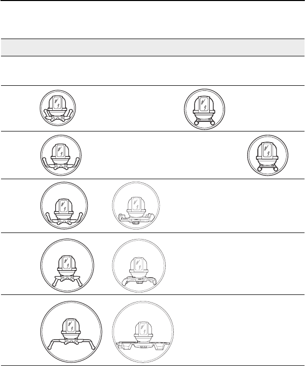
3Use the following chart to
determine how to set up the laser
so the laser beam is centered in the
following pipe sizes.
Table 5.1 Mounting Plates Setups
Pipe Diameter Required Mounting Accessories
1228 1230/1237 1238 1249 Setup
150 mm or 6 inch None 1
200 mm or 8 inch Legs Up 92
225 mm or 9 inch Legs Up 93
250 mm or 10 inch Legs Up 94
300 mm or 12 inch Legs Down 95
400 mm or 15 inch Legs Down 96
Applications and Setups 5
DG711 and DG511 Pipe Laser User Guide 33
Illustration
Setup 1228 1230/1237 1238 1249
1
2
3
4
5
6

5 Applications and Setups
34 DG711 and DG511 Pipe Laser User Guide
Elevation of Flat Bottom
Manholes 5.4.3
1When a laser is to be set on a
flat surface where the laser beam is
not centered in the pipe, use model
1230/1237 Heavy Duty Trivet
Plate and 1239 Universal Fixed
Pole.
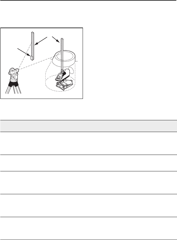
2Using this system, the elevation
of the laser beam can be set by
either measuring down from a
grade offset hub outside the trench
or up from the floor of the manhole
to the beam.
3The 1239 Universal Fixed
Trivet has both cm/mm and
tenths/hundredths scales for setting
the beam elevation.
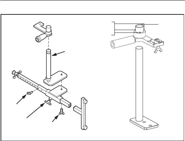
1230/1237 Heavy Duty
Invert Plate 5.4.4
The invert plates model 1230
(English) and 1237 (Metric) are
one piece cast aluminum support
plates that provides automatic self-
centering of the Laser in 250 mm
(10 in.), 300 mm (12 in.) or 400
mm (15 in.) pipe diameters. The
invert plates are used along with
the 1239 Universal Fixed Pole for
setups on the manhole bottom,
outside of the manhole or in pipes
larger than 400 mm (15 in.)
diameter.
Applications and Setups 5
DG711 and DG511 Pipe Laser User Guide 35
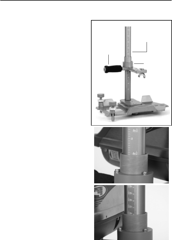
1239 Universal Fixed
Pole 5.4.5
The 1239 Universal Fixed Pole
supports a laser at a predetermined
elevation above the invert. Use the
1239 with the 1228 Universal
Adjustable Invert Plate, 1230/1237
Heavy Duty Invert Plates, or 1244
T-Bar Assembly.
Features:
1Pole Clamp #1 – slides onto the
vertical pole and is secured with
the pole clamp’s handle.
2Top Pole Scale (TPS) –
determines the distance between
the top of the pole to the center of
the laser beam.
3Mounting Plate Scale (MPS) –
determines the distance between
the center of the laser beam and the
bottom of the Model Mounting
Plate. This scale is represented
with down arrows next to the scale
numbers.
1239 universal
fixed pole mounted
on 1230/1237 heavy
duty invert plate
Clamp #2
Clamp #1
5 Applications and Setups
36 DG711 and DG511 Pipe Laser User Guide
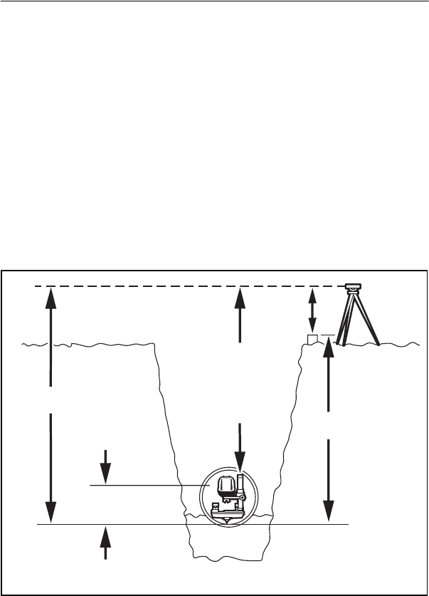
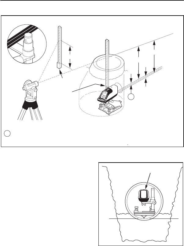
Method 1: Using the Top Pole
Scale (TPS)
Grade rod set on top of the Fixed
Pole.
Note – First decide the laser
beam’s elevation above the invert.
1Record the “cut-to-invert”
information from the grade hub.
2Set up an automatic level and
measure its elevation (HI) above
the grade hub.
3Set a grade rod on top of the
Fixed Pole and record the
measurement with the automatic
level.
4Subtract the desired laser beam
elevation above the pipe’s invert.
5Calculate the TPS setting.
Laser beam distance
above invert
Rod reading
on grade
hub
Rod reading on top
of fixed pole
Cut to invert
HIn
Applications and Setups 5
DG711 and DG511 Pipe Laser User Guide 37
The laser is now at the proper
working elevation.
Surveyor rod
Grade hub
Table 5.2 Example 1: Setting the Grade Rod on top of the Top Pole
Scale
Step Description Metric Ft / Inch
Step 1 Decide what elevation the laser
beam shall be used above the
invert.
0.152 m 0.5 ft
Step 2 Record the “Cut to Invert”
information from the grade hub.
0.805 m 2.64 ft
Step 3 Measure the elevation (HI) of the
optical instrument above the
grade hub.
1.128 m 3.70 ft
Step 4 Subtract the measured distance
from the optical instrument to the
top of 1239 Universal Fixed Pole
-1.635 m -5.38 ft
Step 5 Subtract the desired elevation of
the laser beam above the pipe’s
invert.
-0.152 m -0.50 ft

5 Applications and Setups
38 DG711 and DG511 Pipe Laser User Guide
Step 6 Calculated TPS = 0.805 m
1.128 m
-1.635 m
-0.152 m
0.146 m
2.64 ft
3.70 ft
-5.38 ft
-0.50 ft
0.46 ft
Step 7 Adjust the pole clamp until the reading edge is aligned with the
TPS reading (0.146 m or 0.46 ft)
Step 8 The laser beam is now set at your desired working elevation
(152.4 mm / 6 inches / 0.5 ft ) above the invert of the proposed
pipe.
Table 5.2 Example 1: Setting the Grade Rod on top of the Top Pole
Scale (Continued)
Step Description Metric Ft / Inch
Applications and Setups 5
DG711 and DG511 Pipe Laser User Guide 39
Method 2: Setting Grade Rod
on Top of Laser
Note – Using this method, the
offset distance of 70 mm (0.23 ft)
between the top of the Laser
housing and the center of the laser
beam will be used.
1Decide what elevation of the
laser beam shall be used above the
invert.
2Record the “cut-to-invert”
information from the grade hub.
CI = 0.805m
(2.64')
AKS = 1.933m (6.34') - 0.152m (.5') - 1.635m (5.38') = 0.146m (0.46')
1.128m (3.70')
14.6cm (0.46')
HIn = 1.933m (6.34')
1.635m (5.38')
0.152m (0.5')
A
A
Rod reading set on
top of fixed pole
Rod reading on top of laser
5 Applications and Setups
40 DG711 and DG511 Pipe Laser User Guide
3Set up an automatic level and
measure the elevation of the
automatic level above grade hub.
4Add elevation measurement of
instrument to “cut-to-invert” from
grade hub.
5Subtract the desired working of
elevation of laser beam above
invert.
6Subtract the beam offset
(70 mm / 0.23 ft).
7Calculate new rod reading.
8Set the rod on top of the laser
and adjust the elevation of the laser
until the correct rod reading is
observed.
9The laser beam is now at the
proper working elevation.
HIn
Laser beam distance
above invert
Rod reading
on top of laser
Rod reading
on grade hub
Cut to invert
Table 5.3 Example 2: Setting Grade Rod on Top of Laser
Step Description Metric Ft / Inch
Step 1 Decide what elevation the laser beam
shall be used above the invert.
0.152 m 0.5 ft
Step 2 Record the “cut-to-invert” information
from the grade hub.
0.805 m 2.64 ft
Step 3 Measure the elevation (HI) of the
optical instrument above the grade
hub.
1.128 m 3.70 ft
Step 4 Add elevation measurement of
instrument to “cut-to-invert” from grade
hub.
1.635 m 5.38 ft

Applications and Setups 5
DG711 and DG511 Pipe Laser User Guide 41
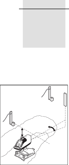
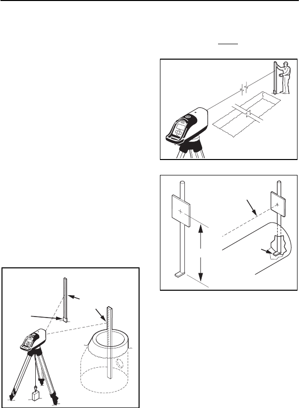
Setting Line 5.4.6
The principle for setting line is
always the same. The laser is
positioned over the starting point
of the pipe run then aimed to the
second control point on line. The
further your second point is from
the laser, the more accurate your
line will be.
First Point Setup (Using
Plumb-bob) 5.4.7
Whether using the laser in the
invert or attached to the various
mounting plates the goal is to
always set the laser’s line axis
bull’s-eye target over the vertical
centerline of the pipe.
Step 5 Subtract the desired elevation of laser
beam above the pipe’s invert.
-0.152 m -0.50 ft
Step 6 Subtract beam offset (70 mm / 0.23 ft). -.070 m -0.23 ft
Step 7 Calculated Rod Reading = 0.805 m
1.128 m
-0.152 m
-0.070 m
1.711 m
2.64 ft
3.70 ft
-0.50 ft
-0.23 ft
5.61 ft
Step 8 Set the rod on top of the Laser and
adjust elevation until the correct rod
reading is observed.
1.711 m 5.61 ft
Step 9 The laser beam is now set at your desired working elevation
(152.4 mm / 6 inches / 0.5 ft) above the invert of the proposed
pipe.
Table 5.3 Example 2: Setting Grade Rod on Top of Laser
Step Description Metric Ft / Inch
5 Applications and Setups
42 DG711 and DG511 Pipe Laser User Guide
This is accomplished by one of the
following methods:
1Place the bull’s-eye target
under a plumb bob that has been
transferred from an offset grade
hub.
2If using a transit or theodolite,
align the bull’s-eye target to the
vertical cross hair of the transit’s
telescope.
3If the bull’s-eye target cannot
be seen, use the plus sign on the
positive grade button to align the
target to the vertical cross hair of
the transit.
4In an over-the-top setup, set the
laser on a tripod and plumb bob
them over the first grade stake.
Applications and Setups 5
DG711 and DG511 Pipe Laser User Guide 43
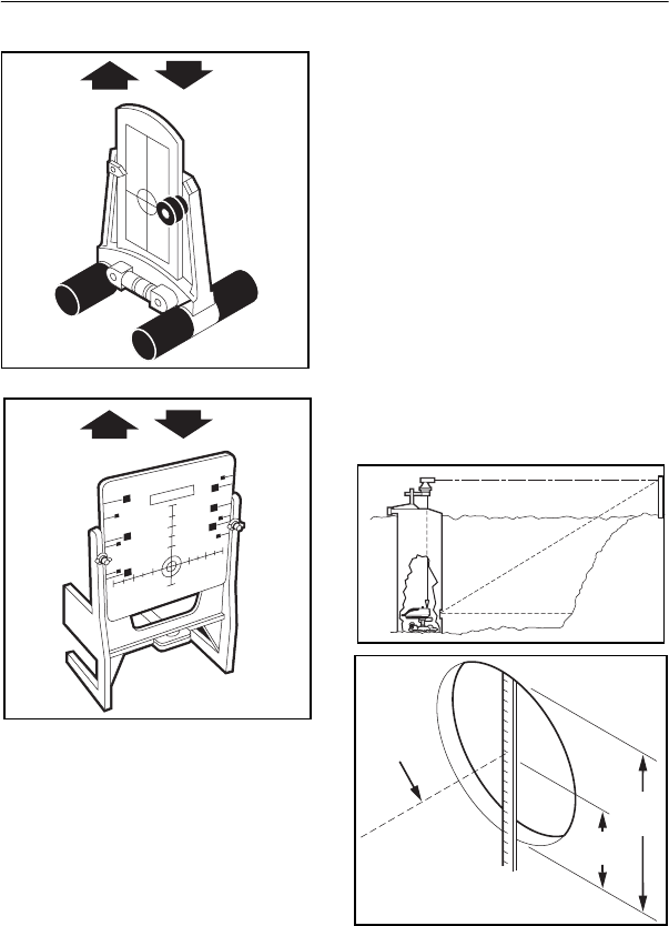
1211 Laser Plummet
Line Setting 5.4.8
The laser plummet may be used in
place of the Plumb-bob by
attaching it under the tripod or
manhole mount.
1Position the laser plummet over
the laser’s bull’s-eye reflective
target into the manhole mount or
tripod replacing the 5/8 x11
attachment thread.
2Quickly turn the product upside
down to activate the compensator
and turn the power switch "on".
3If the bull’s-eye target cannot
be seen, align the Laser Plummet
to the plus sign on the positive
grade button on the keypad or
anywhere along the center of the
laser.
4In an over-the-top setup, set the
laser on a tripod and align the
Laser Plummet over the first grade
stake.
Second Far-Point
Alignment 5.4.9
1Simultaneously press both Left
and Right Line buttons to center
the laser’s ±10° of line travel.
2Press either Line button to align
the laser beam to the second
control point. If using a wireless
remote control, point the remote
towards the laser and press the
appropriate line button.
Note – Line speed increases the
longer you press the line button. To
slow the line speed, release the line
button then press again.
Next manhole

5 Applications and Setups
44 DG711 and DG511 Pipe Laser User Guide
Setting Line with the
Line Set/Check Featu
re 5.4.10
The Line Set / Check feature,
available with the DG711, can be
used to align the beam to a forward
grade hub by moving the laser to
its maximum leveling limit then
returning it to the original grade
setting. Line Set/Check is
beneficial for setting line if a
manhole mount or transit is not
available.
Note – Before using Line
Set/Check, the Laser must be
accurately positioned for cross-
axis roll to ensure that the laser
beam will track plumb. Consult
your salesman or service personnel
to activate the Line Set/Check
feature.
Activating the Cross
Axis Roll Option 5.4.11
1Quickly press and release the
ON/OFF button to enter the Laser’s
Status mode.
2While the Battery gauge is
displayed, press and release either
Grade button to display the Laser’s
cross axis roll position.
3If the Laser is being used in a
pre-cast invert, roll the unit until
the cross-axis roll indicator is
centered and display indicates two
arrows pointing at each other (roll
center) instead of multiple arrows
pointing to the left or to the right.
4Quickly press and release the
ON/OFF button to return to the
grade display.
5If the Laser is being used with a
1228 on a flat surface, the Laser
must be attached perpendicular
(90°) to the 1228 Universal
Mounting Plate.
6The footscrews used with the
1230/1237 plate can be used to
help center the roll indicator and
display indicates two arrows
pointing at each other.
Applications and Setups 5
DG711 and DG511 Pipe Laser User Guide 45
Activating Line
Set/Check Raise 5.4.12
1Simultaneously press the
ON/OFF and the “+” Grade button
to activate Line Set/Check.
Note – For RC502 7-Button
Remote Control users, the ± Grade
enable key must be pressed and the
Red Grade enable LED must be
blinking before the remote will
active Line Set/Check.
2To stop Line Set/Check as it
approaches the line point, press
either Grade button.
3To continue raising grade,
simultaneously press the ON/OFF
and the “+” Grade button.
4If you overshoot and wish to
lower grade, simultaneously press
the ON/OFF and the “-” Grade
button.
5Once the line position is set,
press and release the ON/OFF
button to return the laser beam to
your original grade setting.
Grade enable key
5 Applications and Setups
46 DG711 and DG511 Pipe Laser User Guide
Activating Line
Set/Check Lower 5.4.13
1Use Line Set/Check Lower
when the laser is set on a tripod for
over the pipe applications.
2Simultaneously press the
ON/OFF and the “-” Grade button
to activate Grade Lower.
Laying Pipe/Setup
1First Day Setups – Use the line
buttons to align the laser to the next
manhole.
2Second day setups – Select a
target that can establish the
centerline or distance above the
invert in your pipe. Set the target in
the last pipe checked to the correct
grade, elevation, and line.
3Align the laser to the target
using the line buttons on the laser
or using the wireless remote.
4Lay Pipe – set the target in each
new section of pipe and adjust the
pipe until the laser intersects the
target’s bull’s-eye.
Level vial
Undisturbed pipe
set at correct grade
elevation & line
Next manhole
Applications and Setups 5
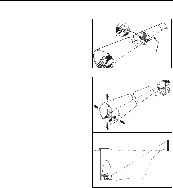
DG711 and DG511 Pipe Laser User Guide 47
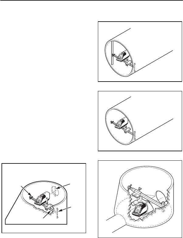
Large Pipe 5.4.14
The laser can be set directly on the
flow line using the various
mounting plates or a 1244 T-bar for
increased stability and an
unobstructed flow line.
1Set Grade Elevation, and Line
into the Laser for large pipe
applications.
2Set an adjustment pipe target so
that the targets’ bull’s-eye is at the
same distance above the invert as
your laser.
3Place the pipe target in the last
section of the pipe that has been
checked to be at the correct grade,
elevation and line.
4Adjust the pipe target until it’s
level vial reads level.
5Align the laser to the target’s
bull’s-eye using the line buttons on
the laser or the Wireless Remote.
6Lay Pipe – Set the target in
each new section of the pipe and
adjust the pipe until the laser
intersects the target’s bull’s-eye
while the target is level.
Level
vial
5 Applications and Setups
48 DG711 and DG511 Pipe Laser User Guide
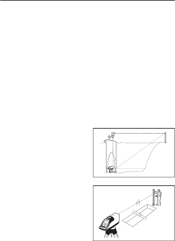
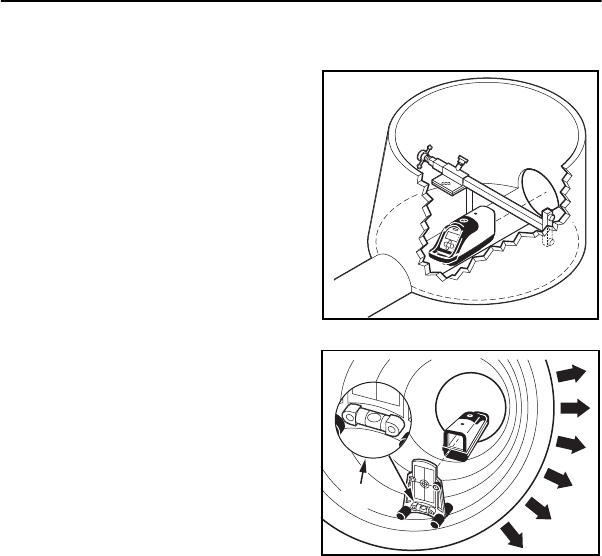
In a Manhole 5.4.15
The laser can be set up in a
manhole using a transit to
accurately set line. The transit is
plumbed over the laser on a mount
that clamps to the manhole. The
laser is projected down the center
of the pipe.
1Set the laser support in the
manhole and attach it to the
support.
2Adjust the laser to the chosen
height above the invert and on the
vertical centerline of the exit hole
for the proposed pipe.
3Point the laser towards the next
manhole.
4Hold an engineering rule on the
vertical centerline and adjust the
laser’s height to the desired height
above the invert.
Laser beam
30.5 cm pipe
15 cm radius
30.5 cm dia
(12 in.)
(6 in.)
(12 in.)
Applications and Setups 5
DG711 and DG511 Pipe Laser User Guide 49
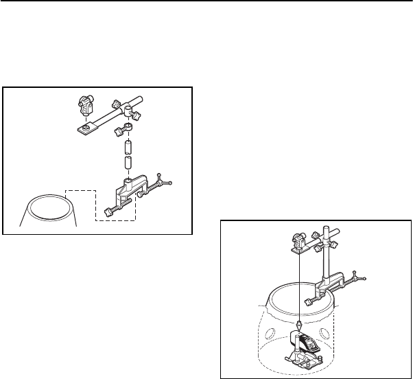
Line (transit method)
1Set a manhole mount and
transit on the manhole.
2Clamp the manhole mount base
to the side of the manhole to
establish a stable transit support.
3Secure the vertical arm into the
manhole mount base.
4Assemble the horizontal arm,
horizontal clamp, and vertical
support clamp to the vertical arm
and position over the top of the
laser.
5Attach your transit to the
5/8 ×11 threaded adapter in the
horizontal arm.
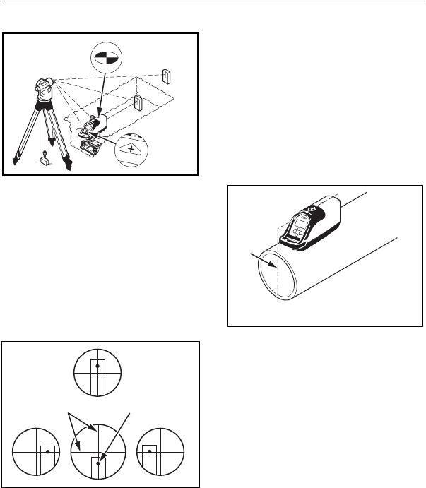
6Transit Alignment – You may
position your transit over the
laser’s bull’s-eye target in one of
the following methods:
aUse the Laser Plummet and
if your transit is equipped with
an optical plummet, adjust the
horizontal arm to position the
transit’s optical plummet over
the lasers’ bull’s-eye target.
bPlumb Bob: If your transit
does not have an optical
plummet, suspend a plumb bob
from the transit, and align it
over the lasers’ bull’s-eye
target.
7After rough positioning the
transit over the bull’s-eye target,
use the transit's leveling base to
accurately adjust the transit to the
bull’s-eye target.
8Once the transit is set over the
lasers’ bull’s-eye target, sight the
transit on the centerline of the next
manhole and lock the scope on
line.
5 Applications and Setups
50 DG711 and DG511 Pipe Laser User Guide
9Plunge the scope into the trench
and set a stake on line 6–8 m (20–
25 ft) from the first manhole.
10 Use the line buttons to intersect
the stake with the laser beam.
11 Look through the transit at the
stake and readjust the beam until it
is aligned with the vertical
crosshair of the transit.
12 Lay pipe – Set the pipe target in
each new section of pipe and adjust
the pipe until it intersects the
target’s bull’s-eye.
Note – This method assumes that
the manhole was set at the correct
elevation. If there is any question
as to the manhole accuracy, check
the manhole and pipe invert
elevation and transfer an offset to
check the line of pipe entering or
exiting the manhole.
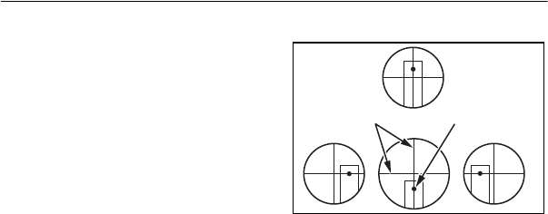
On Top of the Pipe
1Line – Set the laser until it is
over the vertical centerline of the
pipe and pointing toward the next
manhole.
Note – It may be necessary to
support the Laser with extra
gravel, dirt, or sub-base material.
2Set an adjustable pipe target
(Model 936 or 956) so that the
target’s bull’s-eye is at the same
distance above the pipe as your
laser beam.
A
B
Next manhole
No No
Transit
crosshairs
Ye s
Laser spot
Vertical centerline

Applications and Setups 5
DG711 and DG511 Pipe Laser User Guide 51
3Place the pipe target on top of
the last section of pipe that has
been checked to be at the correct
grade, elevation, and line.
4Adjust the pipe target until its
level vial reads the target is level.
5Align the laser to the targets’
bull’s-eye using the line buttons on
the laser or the Wireless Remote.
6Lay Pipe – Set the target on top
of each new section of pipe and
adjust the pipe until the laser
intersects the targets’ bull’s-eye
while the target is level.
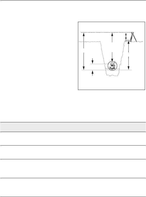
Open Excavations 5.4.16
1Set a transit over the first point
on the proposed pipeline behind
the manhole where the pipe run
starts.
2Align the transit to the next
manhole and lock the transit on
line.
3Plunge the transit into the open
excavation where the manhole will
be placed.
4Set the mounting plate and the
1239 Universal Fixed Pole on
stable sub-base material in the
open excavation and on line.
5Grade – Enter grade into the
Laser.
6Attach the laser to the 1239
Universal Fixed Pole.
7Sight through the transit at the
laser.
Level vial
Undisturbed pipe
set at correct grade
elevation & line
A
B
Next manhole
5 Applications and Setups
52 DG711 and DG511 Pipe Laser User Guide
8Adjust the laser and the
mounting plate until the bull’s-eye
target or “+” symbol on the
positive grade button is aligned
with the transit’s vertical crosshair.
9Elevation – Determine the
correct elevation for the invert of
the proposed pipe.
10 Determine if you wish to set the
laser beam on the centerline of the
pipe or at a constant distance above
the flow line.
11 Adjust the laser until you are at
the chosen height above the invert.
12 Set an adjustable pipe target
(Model 936 or 956) so that the
target’s bull’s-eye is at the same
distance above the invert as your
laser beam.
13 Plunge the transit into the open
excavation and set a stake on line
6–8 m (20–25 ft) from the next
manhole.
14 Line – Look through the transit
at the next stake; align the laser to
the vertical crosshair of the transit
using the Line buttons on the laser
or the Wireless Remote
15 Lay Pipe – Set the target in
each new section of pipe and adjust
the pipe until the laser intersects
the target’s bull’s-eye while the
target is level.
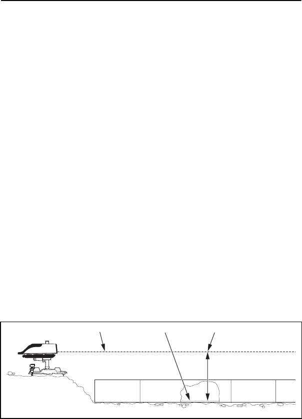
Over the Top 5.4.17
The laser can be set on a tripod or
mounting plate above the
excavation on the pipe itself. A
laser target is mounted on a pole
and is adjusted to give the correct
distance from the beam to the pipe
invert. For accurate line control, a
level vial can be attached to the
pole to ensure that the target is held
vertically. This is an excellent
setup for shallow cuts for trenches
where water is present.
1Attach the laser to a tripod
having a 5/8 inch x 11 thread.
No NoYe s
Transit
crosshairs Laser spot
Applications and Setups 5
DG711 and DG511 Pipe Laser User Guide 53
2Set the tripod and laser on line
behind the first manhole and
ensure the system is level.
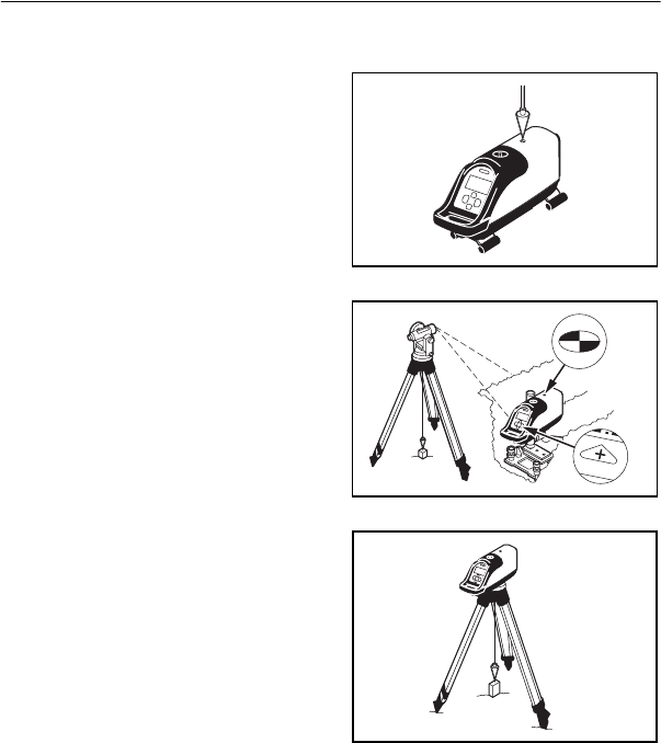
3Suspend a plumb bob from the
tripod or use a Laser Plummet over
the first point.
4Transfer the elevation into the
manhole using a level, transit, or
with your laser set to 0.00% grade.
5Set a stake on the centerline of
the pipe so the top of the stake is at
invert elevation.
6Use the wireless remote to
position the beam on the rod as you
take your readings.
7Add your grade rod reading to
your cut-to-invert reading.
8Set a target on rod at this
distance. For example:
Rod reading = 6.48
Cut-to-invert = 4.51
Set to = 10.99
Grade hub
C.I.
Grade rod
reading
Instrument method-manhole
10.99
Laser beam
Pipe
invert

5 Applications and Setups
54 DG711 and DG511 Pipe Laser User Guide
DG711 and DG511 Pipe Laser User Guide 55
CHAPTER
6
DG511/711
Additional
Accessories 6
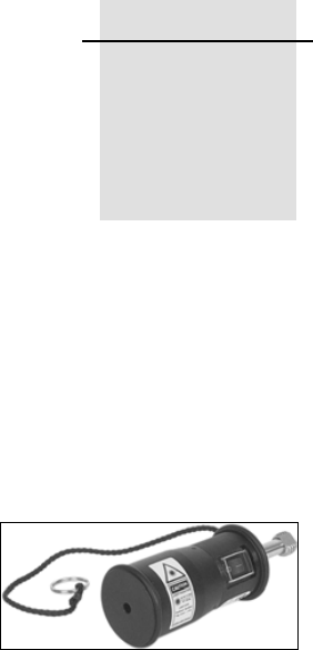
1211 Laser
Plummet 6.1
Replaces the 5/8-11 bell housing in
manhole mounts or tripods, and
provides a self plumbed laser dot
that can be quickly positioned over
the plumb point. This greatly
reduces first day setup time.
The 1211 has a self-plumbing
range of 10 degrees, a bright 635-
nm beam, safety lanyard, shock
bumpers, and operates off two
AAA batteries (included). The
1211 includes operating
instructions and a carrying pouch
with belt loop.
Note – You must turn the 1211
upside down then right-side up just
prior to each use. For setup and
operating instructions, see the
1211 operator’s manual.
6 DG511/711 Additional Accessories
56 DG711 and DG511 Pipe Laser User Guide
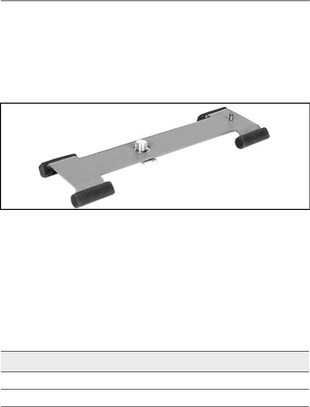
1238/1249 Mounting Plates 6.2
Allows the laser to automatically center in an 200 mm (8 inch) diameter
pipe using 1238 mounting plate and 225 mm (9 inch) diameter pipe using a
1249 mounting plate.
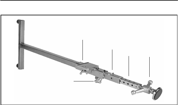
1244 and 1244-1
T-Bars 6.3
The 1244 T-Bar is a mounting
support system for using a laser in
large diameter pipe, manholes, or
open excavated trenches where
high stability and a variable
elevation adjustment is required.
Use the 1244 with a 1239
Universal Fixed Pole for precast
invert setups for unobstructed
flowlines.
Also use the 1244 in large diameter
pipe to place the laser beam
parallel to the pipe’s centerline.
Pipe Diameter Application Recommended T-Bar
1.07 to 2.03 m (42 – 80 inch) 1244
0.83 to 1.58 m (33 – 66 inch) 1244-1
DG511/711 Additional Accessories 6
DG711 and DG511 Pipe Laser User Guide 57
Note – Both models can be shortened for use in smaller diameter pipes and
manholes. The speed release handle provides 13 cm (5 inches) of fine
adjustment range.
Features 6.3.1
1Mounting Plate – supports the
laser or the 1239 Universal Fixed
Pole.
2Locking Pin – holds the
extension bar in place.
3Extension Bar – allows for 25
mm (one-inch) coarse adjustments
in the T-Bar’s overall length.
4Speed Release Handle –
tightens the T-Bar into place and
allows for quick release.
5Horizontal Lock Knob – allows
the mounting plate to slide freely
along the extension bar and
positions the laser on line.
Reverse the Teflon reading edge
assembly when used with the
T-Bar by unthreading the three
screws fastening the assembly to
the pole clamp. Reverse the unit
wing nut capturing screw on the
pole clamp as necessary based on
whether the pole is mounted above
or below the T-Bar.
1
2
34
5
6 DG511/711 Additional Accessories
58 DG711 and DG511 Pipe Laser User Guide
Fixed pole
Adjustable
pole lock
Horizontal
lock
Locking pin
Screws
Tefl o n
edge
reading
DG511/711 Additional Accessories 6
DG711 and DG511 Pipe Laser User Guide 59
Setup Instructions 6.3.2
1Attach the vertical pole to the
T-Bar.
2Adjust the length of the T-Bar
using the locking pin to fit your
setup.
Note – The “T” section of the bar
must be vertical.
3Use the speed release handle to
secure the T-Bar in the manhole or
large pipe at a position that enables
the vertical pole to support the
laser at the predetermined
elevation.
4Loosen the horizontal lock
knob to allow the laser and
mounting plate to be adjusted to
the line of the pipe.
Speed release
handle
Ver tical
centerline
T- b a r
T- b a r
section

6 DG511/711 Additional Accessories
60 DG711 and DG511 Pipe Laser User Guide
Pipe Targets 6.4
The correct target you use depends on the elevation of the laser beam above
the pipe invert and your personal preference.
Through the Pipe Applications 6.4.1
For pipes with a diameter of 500 mm (21 inches) or less, the laser beam is
normally projected on the centerline of the pipe. When the target is
calibrated to the pipe’s diameter, the target may be used in any orientation
in the pipe to maintain the target’s bull’s-eye on center with the pipe.
When the laser is set above the flow-line other than the pipe’s centerline,
the target must be leveled in the pipe. If the target is not level, the pipe may
be placed off line or grade.
Pipe Diameter Application Recommended Pipe Target
150 – 300 mm (6 – 12 inches) 956 Target w/small Pipe Target
350 – 500 mm (15 – 21 inches) 956 Target w/large Pipe Target
400 – 800 mm (15 – 30 inches) 936 Target
greater than 800 mm (30 inches) 936 Target
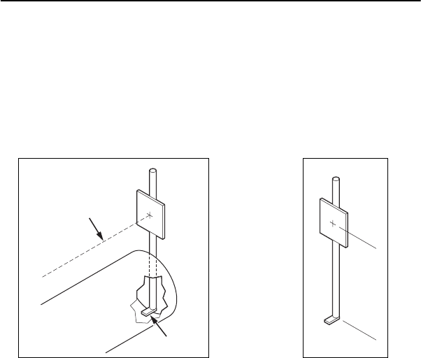
DG511/711 Additional Accessories 6
DG711 and DG511 Pipe Laser User Guide 61
Over the Top Applications 6.4.2
For over the top setups you need to assemble a target from a 25 x 25cm (10
x 10 in.) red or white Plexiglas.
You need a couple of u-bolts, and a 20 mm (¾ in.) rigid or thick walled
plastic pipe of a length to match your setup.
Laser
beam
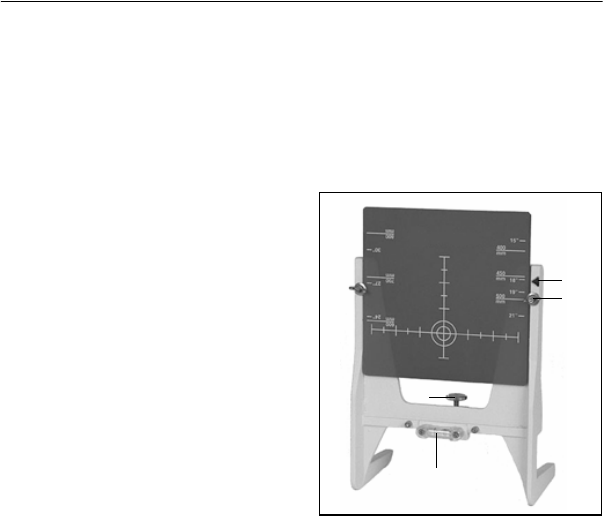
6 DG511/711 Additional Accessories
62 DG711 and DG511 Pipe Laser User Guide
Model 936 Adjustable
Pipe Target 6.4.3
The 936 Adjustable Pipe Target
centers the laser beam in 400–800
mm (15–30 in.) diameter pipes
when the target is aligned to the
scale on the target’s frame.
12 x 4 Mount – used where a
2 x 4 supports the target in a large
pipe when the laser beam is
400 mm (15 in.) above the pipe
inverts. Cut a 2 x 4 to a length and
place in the pipe so the 936
intersects the laser beam on the
bull’s-eye.
2Pipe Bore Mount – used when
the laser beam is near the top of the
pipe. The target hangs upside down
in the pipe and is adjusted until the
beam intersects the target
bull’s-eye. This frees the pipe of
obstructions in the flow line.
3Reference Arrow – calibrates
the target scales for the diameter of
pipe in which the laser is centered.
4Target Clamps – secure the
target into position.
52-Way Level Vial – provides a
level reference for the 936 whether
it is used upright or inverted. A
level target is required where the
elevation of the beam is at some
distance above the invert other than
the pipe’s centerline.
6Lock – secures the target frame
to a 2 x 4 when the 936 is being
used in large diameter pipe.
1 & 2
3
4
6
5
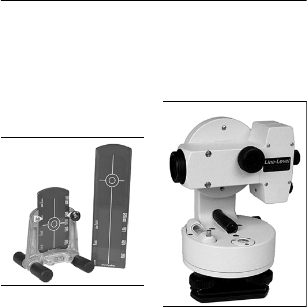
DG511/711 Additional Accessories 6
DG711 and DG511 Pipe Laser User Guide 63
Model 956 Optically
Enhanced Universal
Target 6.4.4
The 956 adjustable Pipe Target
centers the laser beam in 150 to
500 mm (6 to 21 inches) diameter
pipes when the proper target
element is aligned to the scale on
the target’s frame.
Model 1212 LineLevel 6.4.5
The 1212 LineLevel is a rugged
optical instrument that performs as
a precision automatic level and a
line transfer unit for the installation
of gravity flow pipe.
Model 956
Model 1212
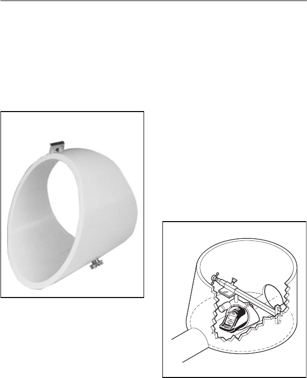
6 DG511/711 Additional Accessories
64 DG711 and DG511 Pipe Laser User Guide
1232 Precast Invert
Adapter 6.4.6
The 1232 Precast Invert Adapter is
used with a 1244 T-Bar and 1239
Universal Fixed Pole when the
laser is positioned slightly above
flowline of a precast invert.
Setup instructions
1Install the 1232 onto the 1239
Universal Fixed Pole.
2Install these components onto a
1244 T-Bar Assembly.
3Set the 1244 T-Bar with the
adjustable pole in the manhole with
the horizontal slide assembly over
the invert.
4Adjust the elevation of the pole
clamp so the laser is placed at the
desired elevation over the flow
line.
5Place a grade rod on top of the
Laser housing to set elevation.
Model 1232
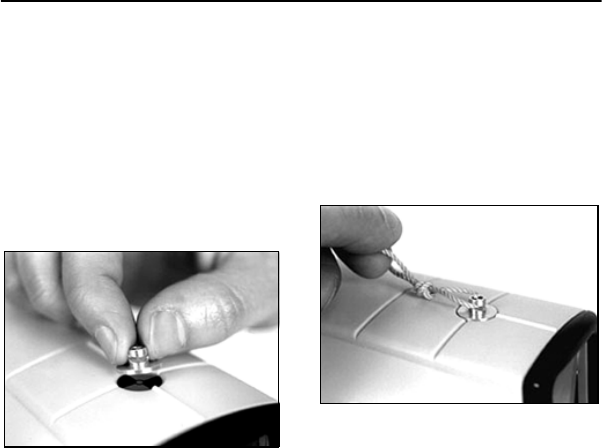
DG511/711 Additional Accessories 6
DG711 and DG511 Pipe Laser User Guide 65
Model 1214 Line String
Adapter 6.4.7
The 1214 Line String Adapter is a
machined aluminum clip with an
adhesive bottom, which is applied
over the laser’s line pivot bull’s-eye
target and used with a plumb bob
for setting the laser on line.
Operating instructions
1Remove the paper from the
adhesive pad on the 1214.
2Press the 1214 over the line
pivot bull’s-eye target on the Laser
making sure the open slot is facing
the front of the Laser.
3Loop a plumb bob string
through the slot on the 1214.
4Standing in a manhole, or
above an open cut, loop the plumb
bob about 30 cm (one foot) over
your hand.
5Move your arm until the two
plumb bob strings are parallel.
6Turn your hand until both
plumb bob strings are in line with
each other, and in line with the next
manhole’s hub.

6 DG511/711 Additional Accessories
66 DG711 and DG511 Pipe Laser User Guide
7Keep the strings parallel and in
line with the next manhole, and
adjust the Laser’s laser spot on line
with the two strings.

DG711 and DG511 Pipe Laser User Guide 67
CHAPTER
7
Refraction 7
1Refraction is the bending of
light at the interface of two
substances caused by a difference
in the speed of light. Shooting a
laser beam through a pipe having
gas and varying temperatures can
be compared to shining a flashlight
beam into a pool of water and
seeing the light bend.
2Refraction of the laser is
preceded by what appears to be a
flaming of the laser spot at the
edges. When this occurs, it is time
to mix the air within the pipe by
some external means such as a
blower. This occurs on sunny days
when a hot pipe is placed in a cool
ditch. The pipe bottom cools first
and the warmer air in the upper
half of the pipe causes the laser
beam to refract down towards the
cooler air.
3Solvent fumes can also cause
refraction from the glue used at
joints, or on very cold days when a
cold pipe is placed in a warm
trench.
4Refraction is a small diameter
pipe problem. When small
diameter pipe is set, it is
recommended to place the hot-sun-
baked side of the pipe down in the
trench so that it will cool faster
against the earth. This helps create
temperature stability in the pipe.
5Generally, refraction of the
laser beam occurs at the last four or
five joints of the pipe. This is
because the last few sun-baked
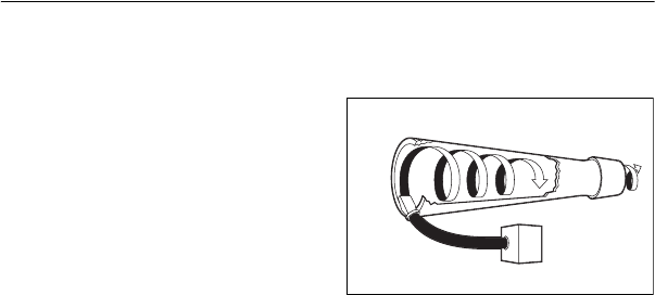
7 Refraction
68 DG711 and DG511 Pipe Laser User Guide
joints of the pipe have not had a
chance to cool in the shade of, and
against the earth of the trench.
6If possible, always back-fill the
pipe as you go. The earth is a great
temperature stabilizer as it
surrounds the pipe. The earth tends
to stabilize the temperature of the
pipe and the air inside. Use of a
blower in conjunction with back-
filling accelerates temperature
stabilization. Always back-fill
immediately unless the jobsite
condition makes it impossible.
7To fully minimize the effects of
refraction, it is advisable to use a
blower after the pipe run exceeds
15 m (50 ft). Operate the blower at
a speed that minimizes the effects
of refraction. As the pipe length
increases, increase the speed of the
blower.
8When using a blower, make
sure it is taking in fresh air through
the intake. On the discharge end,
the nozzle should be angled to
bounce the air off the side of the
pipe thereby creating a spiral or
corkscrew effect.
9If possible, mount the nozzle on
the side of the pipe or in the invert.
Avoid attaching the nozzle at the
top of the pipe unless there is no
other choice, as this will push the
warmer gas through the pipe. If a
strong wind is blowing down the
pipe and fighting the blower, it may
not be needed.
10 In large diameter pipe, 45 cm
(18 inches ) and larger, it is better
to position the blower nozzle off
the invert below the laminar
surface of the gas. If this is
insufficient, three alternatives are
possible. Use two electric blowers,
a Homelite Model III-B (or
equivalent) gas driven blower or a
short blast of air from an air
compressor, to clean out the line.
Nozzle
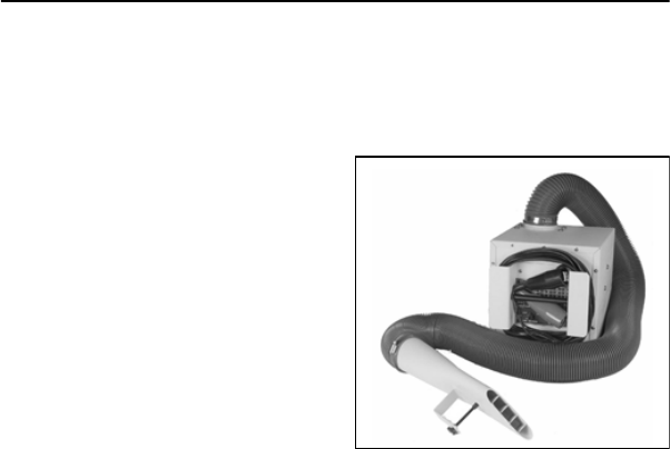
Refraction 7
DG711 and DG511 Pipe Laser User Guide 69
11 If the beam still can not be
controlled, have your backhoe
excavate five buckets full and then
one or two empty buckets as if it
were bailing water. The blower is
pushing heavy fumes in the pipe
that can not get out of the trench
without someone’s help. Cast the
empty bucket on the low side of the
surface or on the downwind side of
the cut.
12 Another solution is to have a
Homelite III-B blower (or
equivalent) at the cut end of the
trench pulling these fumes from the
cut as the electric blower blows
them out of the pipe. This method
does not tie up production and gets
the job done more efficiently.
13 In summary, if all of the above
fail to solve this problem, use the
laser in an over-the-top setup.
Model 929 Blower
Operating
Instructions 7.1
1Use a separate 12-volt
automotive battery to power the
blower.
2Point the nozzle into the pipe to
create a corkscrew effect. This is
the most effective way to create
temperature stabilization.
3Ensure the air intake is not
blocked and the 929 is not set in
water. The support handle/cord
wrap bracket is on the opposite
side of the air intake. This handle
can hook over a manhole step to
keep the unit out of water in the
pipe.

7 Refraction
70 DG711 and DG511 Pipe Laser User Guide
4Start the blower with the first
section of pipe. Use the table on
the blower to determine the blower
speed from the length and size of
pipe being installed. Although very
unlikely, be aware too much air can
also cause refraction.

DG711 and DG511 Pipe Laser User Guide 71
CHAPTER
8
DG511/711
Troubleshooting
8
Table 7.1 will help in troubleshooting your unit. It lists possible problems,
symptoms, and solutions. If the problem goes beyond what is described on
this chart, contact your service center for more information.
Table 8.1 Troubleshooting
Problem Symptom Inspect Solution
Laser does
not come on
No laser
beam
Dead or low battery Change to known
good battery
Laser does
not self-
level
Beam
flashing*
Time allowed for laser
to self-level
Out of level range
Unstable setup
Allow laser to operate
for about 5 minutes
prior to self-leveling.
Roll laser to within its
±3° roll leveling range.
Provide more stable
setup.

8 DG511/711 Troubleshooting
72 DG711 and DG511 Pipe Laser User Guide
Laser does
not respond
to remote
control
Line does
not move
left or right
Line-lock indicator
(status display).
Unlock line or use the
lasers line buttons.
Out of range. Remote
control must be within
150 m (500 ft) when
standing in front of the
pipe laser and 10 m
(30 ft) from behind.
Move the remote
control within range.
Blocked signal. If too
many obstructions are
in the way of the
remote control’s
signal, or the pipe
laser’s collector
windows are dirty, or
the remote control’s
emission window is
dirty, the line will not
operate.
Remove obstruction
and clean windows.
Emission indicator
does not blink or
seems dim.
Return the remote
control to an
authorized service
center.
Line moves
in only one
direction
Line movement is at
limit range.
Reset laser within line
movement range.
Table 8.1 Troubleshooting (Continued)
Problem Symptom Inspect Solution

DG511/711 Troubleshooting 8
DG711 and DG511 Pipe Laser User Guide 73
Grade does
not respond
to grade
control
Grade will
not change
Grade-lock indicator
(status display).
Unlock grade.
Laser beam
is high or
low
Doesn’t
match
existing
pipe
Grade, elevation, or
line is incorrect on
existing pipe.
Use a known accurate
instrument to check
existing pipe.
Unstable setup. Provide more stable
setup.
Check refraction. Use a blower or other
method to stabilize air
temperature in pipe.
Calibration. Calibrate the laser.
Table 8.1 Troubleshooting (Continued)
Problem Symptom Inspect Solution

8 DG511/711 Troubleshooting
74 DG711 and DG511 Pipe Laser User Guide
Note – Flash rate is about one flash per second.
Error
Code
Meaning Action
001 Minimum operating
temperature for the
laser has been
exceeded
Do not operate the pipe laser below
–20°C (–4° F).
Call authorized service center.
002 Maximum operating
temperature for the
laser has been
exceeded
Do not operate the pipe laser above
60° C (140° F).
Call authorized service center.
004 Laser current has
exceeded preset
maximum
Return the pipe laser to an authorized
service center for repair.
016 Grade motor has
jammed.
Check calibration or call authorized
service center.
032 Grade flags failed
initialization.
Return pipe laser to authorized
service center for repair.
064 Fatal Laser Return the pipe laser to authorized
service center for repair.
128 Internal battery
Corrupt
Return pipe laser to authorized
service canter for repair.
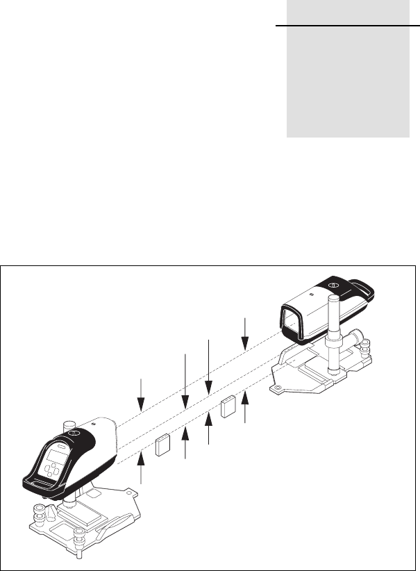
DG711 and DG511 Pipe Laser User Guide 75
CHAPTER
9
Calibration 9
Checking the Calibration 9.1
A2
A
B
A1
B1
B2

9 Calibration
76 DG711 and DG511 Pipe Laser User Guide
Checking the calibration of your
pipe laser is easy. All you need is
an engineer’s rule and your pipe
laser:
1Select a level road, parking lot
or field whose rise is not more than
10 cm in 30 m (4 inches in 100 ft).
2Choose two points (A and B)
about 30 m (100 ft) apart. The
distance does not have to be
measured, but the points must be
found, so mark them well.
3Set up the pipe laser just behind
the lowest point and rough level.
4Turn on the pipe laser and let it
warm up for about 10 minutes.
5Set the grade counter to
0.000%.
6Aim the laser beam so that it
passes over points A and B. Allow
the pipe laser to self-level.
7Accurately measure the
elevation to the center of the beam
at point A and record the elevation
as A1 in a table like the one shown
below:
8Accurately measure the
elevation to the center of the beam
at point B and record the elevation
as B1.
9Move the pipe laser behind
point B and aim the laser beam so
that it passes over points A and B.
Allow the pipe laser to self-level.
10 Accurately measure the
elevation to the center of the beam
at point B and record the elevation
as B2.
11 Accurately measure the
elevation to the center of the beam
at point A and record the elevation
as A2.
Point A Point B
Second Reading A2 B2
First Reading A1 B1
Difference A2 - A1 B2 - B1
Error in 30 m
(100 ft)
(A2 - A1) – (B2 - B1)
2

Calibration 9
DG711 and DG511 Pipe Laser User Guide 77
12 Subtract the A1 and B1
elevation readings from A2 and B2
elevation readings.
Note – Your laser is in calibration
if the difference between A2 – A1
equals B2 – B1.
Note – If A2 – A1 is greater than
B2 – B1, the laser beam is shooting
high and you should readjust the
laser’s calibration bringing the
beam to level.
Note – If A2 – A1 is less than B2 –
B1, the laser beam is shooting low
and you should readjust the laser’s
calibration bringing the beam to
level.
Note – If the error is greater than
6.4 mm/30 m (0.02 ft in 100 ft),
return the pipe laser to an
authorized Trimble service center.
Adjusting the
Calibration 9.2
The goal to adjusting the pipe
laser’s calibration is to make the
beam level, half the distance of the
total error. This will be the true
calibration point of the unit.
1Enter the Calibration feature
option by simultaneously pressing
the power, decrease, and
backlight/lock buttons (buttons 1,
4, 6).
2Press the backlighting/lock
button to enter the selection.
Note – To change the displayed
calibration constants when you are
in the Level Cal. mode, use the left-
or right-line control button
Note – For every 10 digits
changed, the beam’s elevation
changes 1.6 mm/30 m (1/16 inch
per 100 ft).
Note – The maximum adjustable
range is ±120 digits or ±19 mm/30
m (±3/4 inch per 100 ft ).
3When the pipe laser is
calibrated, press the backlight/lock
button to set the calibration.
Note – The laser beam will move to
the new calibration point AFTER
the calibration option is exited and
the normal grade display returns.
The laser will NOT move during
calibration. Verify that the
calibration is correct AFTER
exiting the calibration menu.
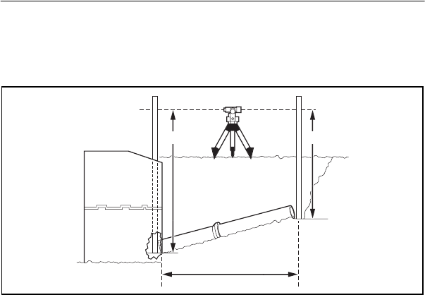
9 Calibration
78 DG711 and DG511 Pipe Laser User Guide
Grade Check 9.3
After the first 8–15 m (25–50 ft) of
pipe has been laid, it is
recommended that you make a
grade check to ensure that the setup
is correct, and that the system is
properly operating.
The illustration shows a method for
checking grade.
1Using a transit level, or an
automatic level and a grade rod,
take a reading at the beginning of
the pipe “A”.
2Using the same instruments,
obtain a level reading at the end of
the pipe “B”.
3The difference between the
readings equals the rise over the
run.
4In terms of % of grade, rise
divided by the run times 100 equals
the percent of grade.
Note – The user of this equipment
is expected to follow all operating
instructions and make periodic
checks on the proper grade,
elevation, and line of the pipe as it
is being laid. Trimble or its
representatives assumes no
responsibility for improperly laid
pipe.
A B

Calibration 9
DG711 and DG511 Pipe Laser User Guide 79
Example 9.3.1
The pipe is laid correctly when the
rod reading “A” minus rod reading
“B” equals the rise according to the
engineering plans.
Table 9.1 Grade check chart
Metric Ft / Tenths
Rod Reading at “A” 4.801 m 15.74 ft
Rod Reading at “B” 3.749 m 12.289 ft
Rise or Difference
(A – B)
1.052 m 3.451 ft
Distance from A to B 44.196 m 145 ft
Rise divided by Run 0.0238 0.0238
Rise divided by Run times
100 = Laser Setting
2.38% 2.38%
Rise according to
engineering plans
(2.38% * 44.196 m) =
1.052 m
(2.38% * 145 ft) =
3.451 ft

9 Calibration
80 DG711 and DG511 Pipe Laser User Guide

DG711 and DG511 Pipe Laser User Guide 81
CHAPTER
10
Maintenance
and Care 10
You will get years of service from
the leveling system by following
the maintenance and care
recommendations in this manual.
Carry the laser in its moisture-
resistant, field-tested carrying case
to safely move the laser from one
job to another.
However well the product is
designed, mishaps do occur. The
most common problems associated
with these are covered in the
following areas.
Storage 10.1
CWarning – Do not store
the laser in a wet carrying
case. If the case gets wet,
open it and let it dry before
storing the laser.
CWarning – Remove the
batteries from the laser
when storing it for more
than 30 days.

10 Maintenance and Care
82 DG711 and DG511 Pipe Laser User Guide
Battery Disposal 10.2
Some countries, states, and local
areas have regulations regarding
the disposal of rechargeable
batteries. Be sure that replaced
batteries are disposed of properly.
System Cleaning 10.3
Use only a good-quality glass
cleaner and a soft cloth to clean all
external optical components. A dry
cloth used on the laser’s/IR remote
control’s optical components or
displays could scratch or damage
these surfaces.
Blow off any loose debris before
cleaning any surfaces to prevent
scratching of optical surfaces.
Monthly, wipe off with a moist,
clean cloth any dust or dirt from
the laser’s outer surface, inside the
battery housing. Clean all corroded
battery contacts with a pencil
eraser or baking soda solution.

DG711 and DG511 Pipe Laser User Guide 83
CHAPTER
11
Laser
Specifications 11
Table 11.1 and Table 11.2 contain the operational specification for the
DG711 and DG511 Pipe Laser.
Table 11.1 Specifications
Performance Specifications
DG511 DG711
Grade Range –15% to +40%
Self-Leveling Range Longitudinal: Over the entire grade range
(no rough leveling required) +/- 3 degrees:
Cross Axis
Line Range 20°
Line Center Yes
Grade Zero Yes
Line Set/Check Yes
Line Alert Yes
Temperature Compensation +/- 30 arc sec. over entire operating range
on DG711

11 Laser Specifications
84 DG711 and DG511 Pipe Laser User Guide
Accuracy, Self-Leveling
(level)
+/- 10 arc seconds = +/- 1.6 mm at 30 m
(1/16 in. at 100 ft )
Maintenance Interval
Notification
Ye s
Warranty Period 1 Year 2 Years
Laser Classification
Laser Source – Visible laser
diode
Laser Wavelength 635 nm
Laser output 4.5 – 5 mW (maximum allowable)
Laser classification USA
and Canada
3A
Laser classification
International
3R
General Specifications
Weight 3.6 kg (8.0 lbs.)
Length 37.5 cm (14.75 inches)
Diameter 14 cm (5 .5 inches)
Housing Material Hard Anodized
Aluminum
Nickel Plated Die
Casting
Battery type and life Alkaline / 40 hours; Ni-MH / 64 hours
Battery pack Sealed (Ni-MH), 0-Ring replaceable
Removable (Alkaline)
Battery Charge Time 10 hrs using the smart charger
14 hrs using the cigarette lighter adapter
Operating voltage 6–16 Vdc
Table 11.1 Specifications (Continued)

Laser Specifications 11
DG711 and DG511 Pipe Laser User Guide 85
Operating temperature –20° to 60° C (–4° to 140° F)
Storage Temperature –30° to 60° C (–23° to 140° F)
Waterproof Continuous Submersion at 3 m (10 ft.)
Table 11.1 Specifications (Continued)
Table 11.2 Remote Control Specifications
Model RC501-
3-Button
Model RC502-
7-Button
Wireless Remote Specifications
Through the Pipe Range 225 m (750 ft) 225 m (750 ft)
Front / Over the Top Range 150 m (500 ft) 150 m (500 ft)
Rear Range 10 m (30 ft) 10 m (30 ft)
Battery life (normal
operation)
2 Years / 24 months 3 Years / 36 months
Functions Line Adjust
Laser On/Off
Line Grade/Adjust
Line Set/Check
Grade Bump
Laser On/Off
Waterproof 3 m (10 ft)
Impact Resistance 1.5 m (5 ft) drop onto concrete
Signal and Battery Indicator Red flashing LED @ 4 Hz
Operating Temperature –20° to 50° C (–4° to 122° F)
Storage Temperature –30° to 65° C (–23° to 149° F)


Laser Specifications 11
DG711 and DG511 Pipe Laser User Guide 87
Survey Instrument Sales
24037 Acacia
Redford, MI 48239
http://surveyinstrumentsales.com/
313-535-5252 Phone

11 Laser Specifications
88 DG711 and DG511 Pipe Laser User Guide

FOL
www.trimble.com
www.trimble.com
DG711 and DG511
Pipe Laser
User Guide
© 2002–2007, Trimble Navigation Limited. All rights reserved.
Reorder PN 1281-0100 Rev. C (09/07)
Trimble Construction Division
5475 Kellenburger Road
Dayton, Ohio 45424-1099
U.S.A.
+1-937-233-8921 Phone
