Spectralink RCH400 Standard Base Station User Manual Installation Information
Spectralink Corporation Standard Base Station Installation Information
Contents
- 1. Regulatory Guide
- 2. Installation Information
Installation Information

Installing the Outdoor Base Station
Link Wireless Telephone System
Part Number: 72-0050-00
Issue D
Supplement to: 72-0075-01 and 72-0059-01

SpectraLink Corporation Installing the Outdoor Base Station
Notice
SpectraLink Corporation has prepared this document for use by SpectraLink personnel and customers. The
drawings and specifications contained herein are the property of SpectraLink and shall be neither reproduced in
whole or in part without the prior written approval of SpectraLink, nor be implied to grant any license to make,
use, or sell equipment manufactured in accordance herewith.
SpectraLink reserves the right to make changes in specifications and other information contained in this
document without prior notice, and the reader should in all cases consult SpectraLink to determine whether
any such changes have been made.
The terms and conditions governing the sale of SpectraLink hardware products and the licensing of
SpectraLink software consist solely of those set forth in the written contracts between SpectraLink and its
customers. No representation or other affirmation of fact contained in this document including but not limited
to statements regarding capacity, response-time performance, suitability for use, or performance of products
described herein shall be deemed to be a warranty by SpectraLink for any purpose, or give rise to any liability of
SpectraLink whatsoever.
In no event shall SpectraLink be liable for any incidental, indirect, special, or consequential damages
whatsoever (including but not limited to lost profits) arising out of or related to this document, or the
information contained in it, even if SpectraLink has been advised, knew, or should have known of the
possibility of such damages.
Trademark Information
SpectraLink
The SpectraLink logo
LinkPlus
Link
NetLink
SVP
Are trademarks and registered trademarks of SpectraLink Corporation.
All other trademarks used herein are the property of their respective owners.
SpectraLink Corporation
5755 Central Avenue
Boulder, CO 80301
303 440 5330 or
800 676 5465
www.spectralink.com
Copyright © 1998 to 2006 SpectraLink Corporation. All rights reserved
Information in this document is subject to change without notice and does not represent a commitment on the
part of SpectraLink Corporation. The software described in this document is furnished under a license and/or
copyright and may only be used with the terms of SpectraLink’s software license agreement as found in this
manual or at http://www.spectralink.com/consumer/resources/software_updates.jsp. The software may be
used only in accordance with the terms of the agreement. No part of this manual, or the software described
herein, may be reproduced or transmitted in any form or by any means, electronic or mechanical, including
photocopying and recording, for any purpose except for the sole intent to operate the product or without the
express written permission of SpectraLink Corporation.
PN: 72-0050-00-D.doc Page 2

SpectraLink Corporation Installing the Outdoor Base Station
WARNING: Changes or modifications to this equipment not approved by SpectraLink
Corporation may cause this equipment to not comply with part 15 of the FCC rules and
void the user’s authority to operate this equipment.
WARNING: SpectraLink products contain no user-serviceable parts inside. Refer servicing
to qualified service personnel.
IMPORTANT SAFETY INFORMATION
Follow these general precautions while installing telephone equipment:
• Never install telephone wiring during a lightning storm.
• Never install telephone jacks in wet locations unless the jack is specifically designed for
wet locations.
• Never touch uninsulated telephone wires or terminals unless the telephone line has
been disconnected at the network interface.
• Use caution when installing or modifying telephone lines
• When installing Base Stations outside or in buildings other than the one containing the
System Controller, take the following precaution:
If wiring for a Base Station exits a building—whether to reach an outdoor Base
Station location or to reach a Base Station in another building—the wiring must be
protected at both ends by a Quick Clip Fuse from Illinois Tool Works, Linx Div
model number SCP-2X2. The Quick Clip Fuse replaces the bridging clips on the 66
blocks for all four connections to the non-internal Ba
ision,
se Station.
PN: 72-0050-00-D.doc Page 3

SpectraLink Corporation Installing the Outdoor Base Station
Table of Contents
1. About This Document 5
1.1 SpectraLink Corporation Model Numbers 5
1.2 Related Documents 5
1.3 Contacting SpectraLink 5
1.4 Icons and Conventions 5
2. Installing Flush Against a Wall or Hard Ceiling 6
3. Installing on an I-Beam 8
4. Installing on a Light Pole or Electrical Pole 9
PN: 72-0050-00-D.doc Page 4

SpectraLink Corporation Installing the Outdoor Base Station
1. About This Document
The Outdoor Base Station is designed to withstand environmental hazards such as
rain and excessive heat and cold. The outdoor enclosure is mounted into position
and the Base Station is then installed within it. The entire unit is then referred to as
an Outdoor Base Station.
This document covers the installation of the Outdoor Base Station in a variety of
situations. It supplements the installation documentation for the Link Wireless
Telephone System using either the Link 3000 MCU or the Link 150 M3 MCU.
1.1 SpectraLink Corporation Model Numbers
This document covers the following registered model numbers:
RCC400, RCO400, RCU100, RCU200, RCU201
1.2 Related Documents
Link 150 M3 MCU: Installation and Operation
(72-0075-01)
Link 3000 MCU: Installation
(72-0059-01)
Available at http://www.spectralink.com/consumer/resources/manuals.jsp.
1.3 Contacting SpectraLink
SpectraLink wants every customer to have a successful installation. Please refer
questions to the Customer Support Hotline at (800) 775-5330. The hotline is open
Monday through Friday, 6 a.m. to 6 p.m. Mountain time.
1.4 Icons and Conventions
This manual uses the following icons and conventions.
Caution! Follow these instructions carefully to avoid danger.
Note these instructions carefully.
NORM This typeface indicates a key, label, or button on SpectraLink hardware.
PN: 72-0050-00-D.doc Page 5
SpectraLink Corporation Installing the Outdoor Base Station
2. Installing Flush Against a Wall or Hard Ceiling
Items provided: Outdoor enclosure, Base Station
Items needed: 4 anchor bolts (length and type depends on wall or ceiling
material Base Station is being mounted to)
1. Mark and drill 4 holes into the wall or ceiling, using the mounting flanges of the
outdoor enclosure as a guide.
2. Mount outdoor enclosure to wall or ceiling using anchor bolts. The outdoor
enclosure can be mounted with the compression fitting in any direction.
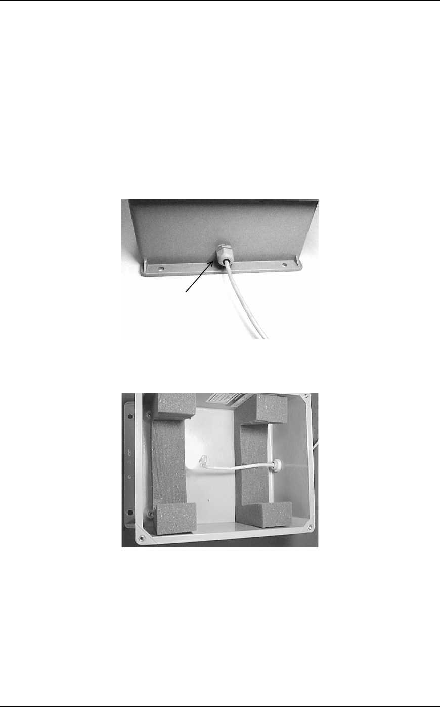
3. Slide the Base Station cable through the compression fitting and tighten fitting.
Compression
fitting
4. Crimp an RJ45 onto the Base Station cable using the same wiring guide as the
indoor Base Station.
PN: 72-0050-00-D.doc Page 6
SpectraLink Corporation Installing the Outdoor Base Station
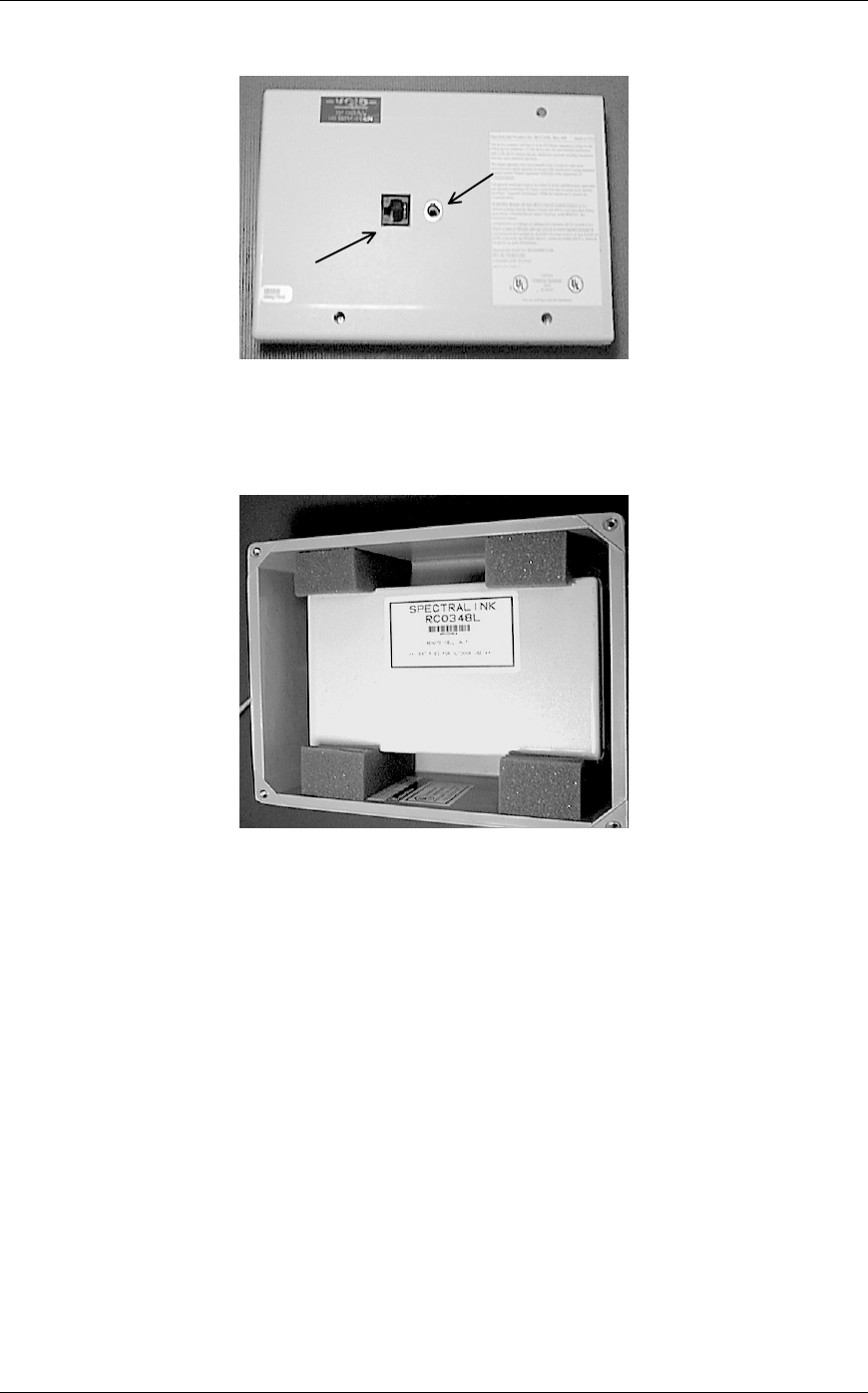
5. Plug the RJ45 into the RJ48C connector.
Mounting
hole
RJ48C
connector
6. Place the Base Station into the enclosure with the side of the Base Station with
the mounting hole facing the wall or ceiling. The Base Station should fit tightly
into the foam blocks.
7. Screw the outdoor enclosure lid back onto the enclosure.
PN: 72-0050-00-D.doc Page 7
SpectraLink Corporation Installing the Outdoor Base Station
3. Installing on an I-Beam
Items provided : Outdoor enclosure, Base Station
Items needed : 4 - “Caddy” or “B-Line” 3/8” Beam Clamps
4 - ½” ¼” x 20 bolts
4 - 2” ¼” x 20 bolts
4 - ¼” x 20 nuts
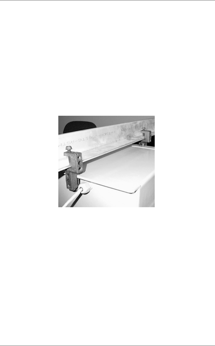
1. Attach a beam clamp to the center of the top and bottom flanges on the outdoor
enclosure.
2. Attach a second beam clamp to each of the beam clamps on the enclosure using
a ½” ¼” x 20 bolt and a nut. (See Picture Below)
3. Attach the outdoor enclosure to I-Beam using the beam clamps attached in step
2.
See figures in Section 2 for pictorial data for the remaining steps:
4. Slide the Base Station cable through the compression fitting and tighten the
fitting.
5. Crimp on RJ45 onto the Base Station cable using the same wiring guide as the
indoor Base Station.
6. Plug the RJ45 into the RJ48C connector.
7. Place the Base Station into the enclosure with the side of the Base Station with
the mounting hole facing the I-beam. The Base Station should fit tightly
between the foam.
8. Screw the outdoor enclosure lid back onto the enclosure.
PN: 72-0050-00-D.doc Page 8
SpectraLink Corporation Installing the Outdoor Base Station
4. Installing on a Light Pole or Electrical Pole
Items provided: Outdoor enclosure, Base Station
Items needed: 4 - “Caddy” or “B-Line” 3/8” Beam Clamps
2 - EOG 100 or Equivalent Band Clamps
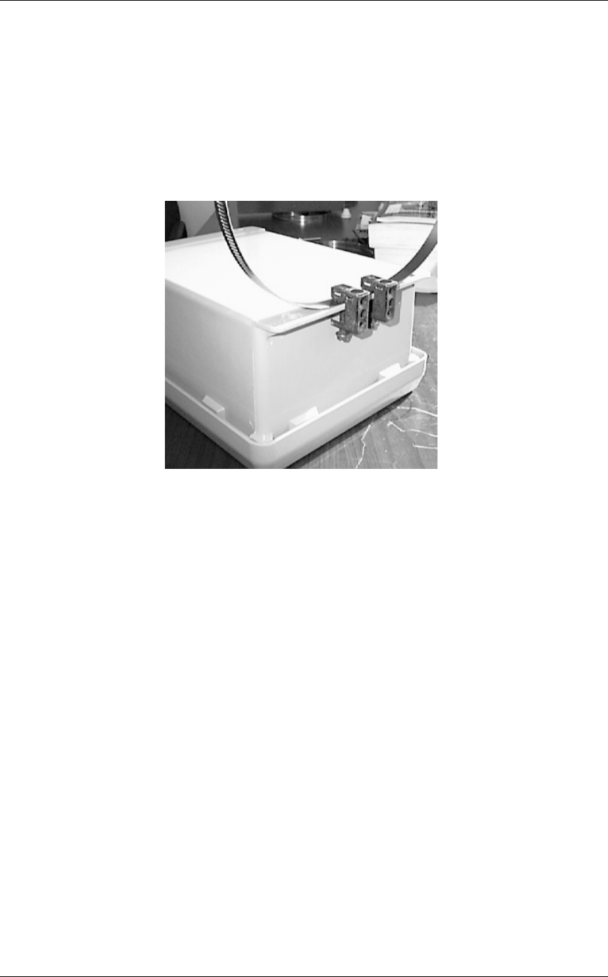
1. Attach one band to the top flange of the outdoor enclosure using 2 beam clamps
(see the figure below).
2. Attach the second band to the bottom flange of the enclosure using the
remaining 2 beam clamps.
3. Wrap the band clamps around the pole and tighten using the screw on the band
clamps.
See figures in Section 2 for pictorial data for the remaining steps:
4. Slide the Base Station cable through the compression fitting and tighten the
fitting.
5. Crimp an RJ45 onto the Base Station cable using the same wiring guide as the
indoor Base Station.
6. Plug the RJ45 into the RJ48C connector.
7. Place the Base Station into the enclosure with the side of the Base Station with
the mounting hole facing the pole. The Base Station should fit tightly between
the foam.
8. Screw the outdoor enclosure lid back onto the enclosure.
PN: 72-0050-00-D.doc Page 9