Spectronic Denmark A S INCA Wireless Audio and PSTN Monitoring System User Manual Manual
Spectronic Denmark A/S Wireless Audio and PSTN Monitoring System Manual
Manual

COMPANY CONFIDENTIAL
Spectronic Denmark A/S
Skindbjergvej 44
DK-8500 Grenaa, Denmark
Telephone +45 86 38 72 22
Fax + 45 86 38 77 04
sales@spectronic-denmark.com
www.spectronic-denmark.com
Wireless Audio and PSTN
Monitoring System
INCA

Page 2 of 48
COMPANY CONFIDENTIAL
Wireless Audio and PSTN Monitoring System INCA
Table of Contents
1 Introduction to Wireless Audio Monitoring......................................4
2 INCA System Introduction .................................................................7
2.1 General..........................................................................................9
2.2 The System ...................................................................................9
2.3 The Transmitter System ..............................................................10
2.4 Transmitter ..................................................................................10
2.5 Remote Receiver / Transmitter ...................................................11
2.6 Power Supply ..............................................................................11
2.7 Receiver ......................................................................................12
3 Technical Specifications INCA ........................................................17
3.1 Test Results – Duracell Alkaline 9V MN1604-6LR61 .................20
4 Parts List – INCA Basic Configuration 1 ........................................22
5 Parts List – INCA Basic Configuration 2 ........................................23
6 Parts List – INCA Basic Configuration 3 ........................................24
7 Parts List – INCA Options ................................................................25
8 INCA TX/RC PSTN Wireless Telephone Line Transmitter ............26
8.1 Introduction..................................................................................26
8.2 System Concept ..........................................................................26
8.2.1 General .............................................................................26
8.2.2 Application Note ................................................................27
8.2.3 Block Schematic................................................................28
8.2.4 Transmitter ........................................................................28
8.2.5 Remote Control Receiver..................................................29
8.2.6 Remote Control Upcodes..................................................30
8.3 Technical Specifications..............................................................31

Page 3 of 48
COMPANY CONFIDENTIAL
Wireless Audio and PSTN Monitoring System INCA
9 INCA TX/RC VOX Wireless Transmitter ..........................................32
9.1 Introduction..................................................................................32
9.2 System Concept ..........................................................................32
9.2.1 General .............................................................................32
9.2.2 Application Note ................................................................33
9.2.3 Block Schematic................................................................34
9.2.4 Transmitter ........................................................................34
9.2.5 Remote Control Receiver..................................................35
9.2.6 Remote Control Upcodes..................................................36
9.3 Technical Specifications..............................................................37
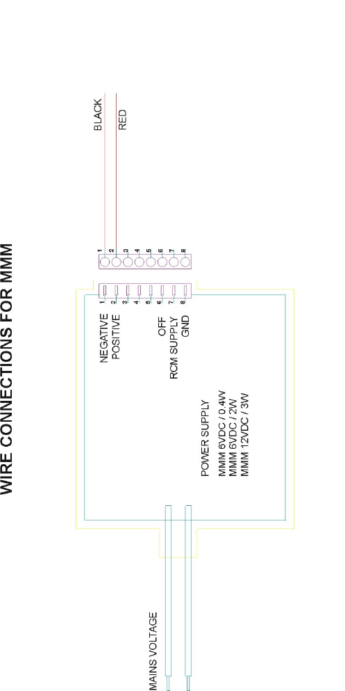
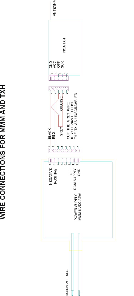
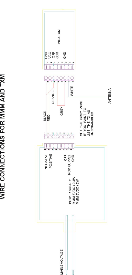
Wire Connections for MMM......................................................................38
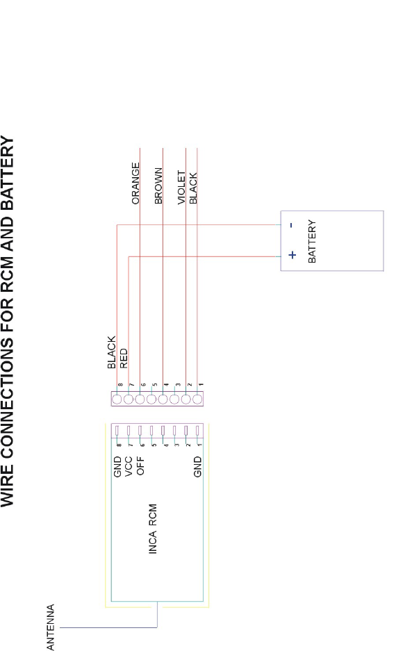
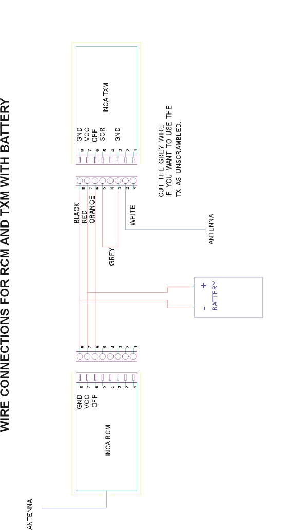
Wire Connections for RCM and Battery...................................................39
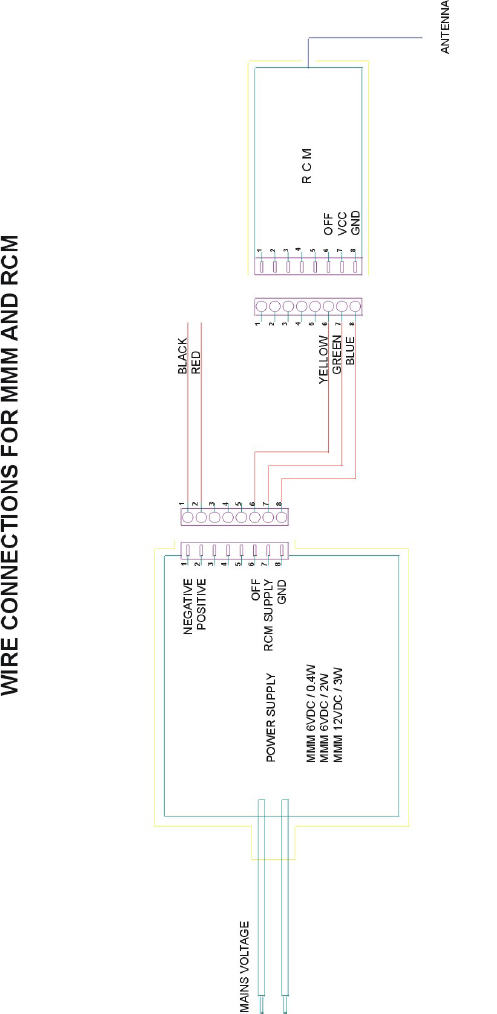
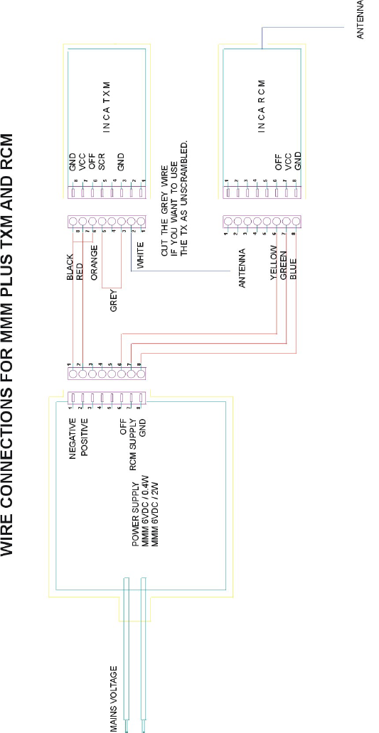
Wire Connections for MMM and RCM .....................................................40
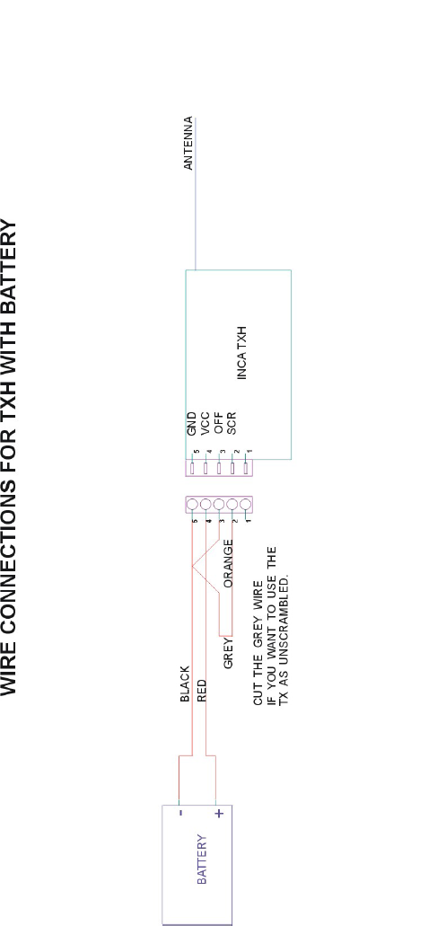
Wire Connections for TXH with Battery ...................................................41
Wire Connections for MMM and TXH ......................................................42
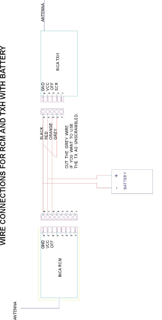
Wire Connections for RCM and TXH with Battery ...................................43
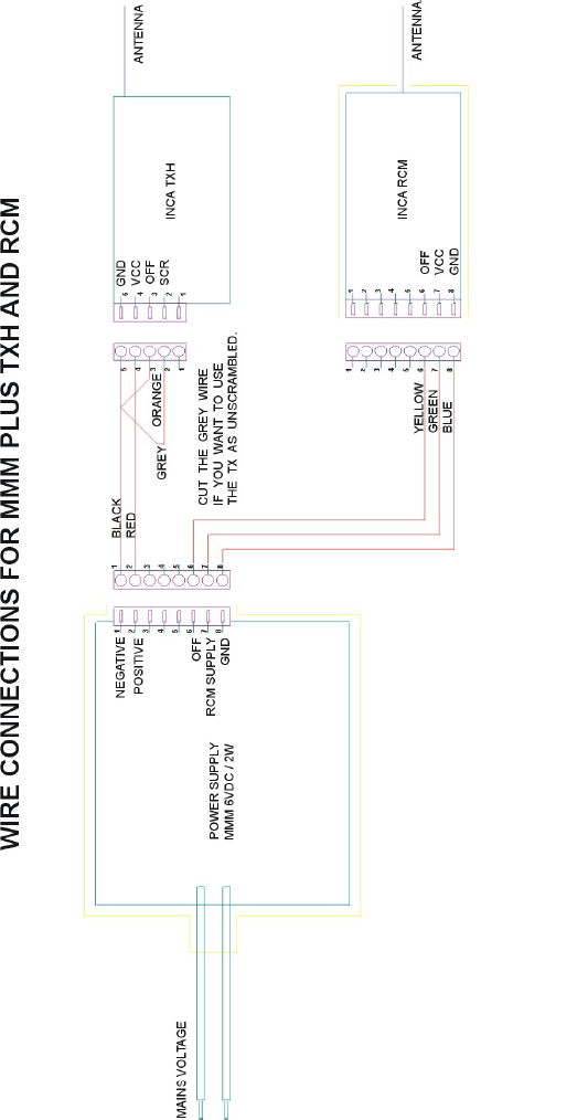
Wire Connections for MMM plus TXH and RCM .....................................44
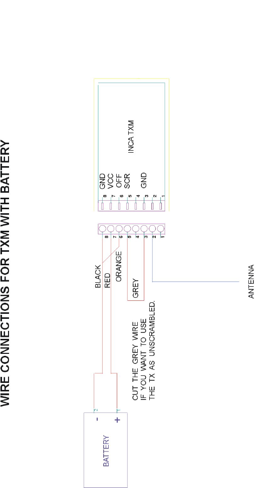
Wire Connections for TXM with Battery ...................................................45
Wire Connections for MMM and TXM......................................................46
Wire Connections for RCM and TXM with Battery...................................47
Wire Connections for MMM plus TXM and RCM .....................................48
Spectronic Denmark
reserve the right to alter all specifications without prior notice

Page 4 of 48
COMPANY CONFIDENTIAL
Wireless Audio and PSTN Monitoring System INCA
1 Introduction to Wireless Audio Monitoring
In today’s increasingly complex environment of electromagnetic
signals in the radio frequency spectrum, wireless audio surveillance
operations are subject to several hostile parameters, which are critical
for operation success and ultimately monitored high-quality audio
signal retrieval. Wireless operations are also subject to many
mysterious theories, but are fairly handable if the right natural laws are
implemented.
Several parameters has to be taken into consideration while using
wireless audio surveillance systems versus wired systems.
Convolutional and additive noise sources are the same, but other very
important matters such as; frequency area, electronic interference,
battery lifetime, operative range, receiving antenna, radio signal
reflections, building layouts and construction techniques, are often
making such operations fairly complex and require good planning
along with the use of professional audio monitoring equipment
designed for the task.
Convolutional Noises are normally related with room resonances
and reverberations as major sources of this type of noise. Large rooms
and lack of sound absorbing material contribute to undesired
convolutional effects.
Additive Noise sources erupt from e.g. radio and TV audio along with
a variety of noises entering from outside like mechanical movements
of the microphone element, air conditioners, motors, street noise or
other machinery.
Frequency Area is important for the operation, as concealment of the
surveillance carrier in the frequency spectrum is of importance if
possible, in order to avoid countermeasures or occasional interception
by third party. The frequency also has to be chosen in connection with
signal path loss i.e. operative distance, as to say the higher frequency
the shorter operative distance and signal penetration of buildings.
Electronic Interference can be avoided to a certain extent but
requires a selective receiver with very good input filtering, which
minimizes interference from other transmitting sources. Only receivers

Page 5 of 48
COMPANY CONFIDENTIAL
Wireless Audio and PSTN Monitoring System INCA
designed specially for the surveillance task, will assure the immunity
and dynamic range required for optimized audio signal retrieval,
easing the work for the transcriptor.
Battery lifetime/-type is another high priority factor, often surrounded
by lots of mystique but it is straight forward and can be calculated by
simply dividing the
transmitter current consumption (measured in mA) into the datas from
the battery specifications (specified in mA/hour).
Operative range is an unpredictable matter mainly linked up with
three major parameters; transmitting power (specified in mW),
operative frequency (specified in MHz), i.e. the higher frequency the
lower range due to signal attenuation in the radio frequency spectrum
as well as the physical surroundings (e.g. buildings or vehicles) for the
operation to be carried out.
Receiving antenna is as important as the radiated power from the
transmitter itself. Making use of the correct antenna on the receiver
side, example a narrow band directional antenna will provide a noise
free amplification of several dB, extending the operative range of a
concealed transmitter considerably e.g. 50 - 100 meter.
Radio Signal Reflection as a normal used antenna is providing a
three-dimensional transmission path, another factor to be aware of is
that a radio signal which has penetrated a buildings internal clutter,
may often be exceeded by a signal, which has taken a more in-direct
reflection route, perhaps by reflection from an adjacent building,
proving a better reception at the receiver/listening post (specially in the
microwave bands i.e. high frequency area).
Building layouts and construction techniques are other very
important factors to take into consideration, where a wireless operation
is to be accomplished.
The loss of the radiated signal will be high in a reinforced concrete
building with internal metal partitions, that impede transmission, versus
a hangar-like building which will act almost like a waveguide. The
various difficulties in such operations are of disadvantage to the audio
surveillance task-team. But if present handrules are taken into

Page 6 of 48
COMPANY CONFIDENTIAL
Wireless Audio and PSTN Monitoring System INCA
consideration, while planning and training for such operations and the
use of high-quality professional monitoring tools designed for the task
are deployed, then a maximum of parameters have been considered by
the surveillance team and a successful operation should be assured.

Page 7 of 48
COMPANY CONFIDENTIAL
Wireless Audio and PSTN Monitoring System INCA
2 INCA System Introduction
Spectronic Denmark has developed a completely new generation of
professional, highly advanced, micro-size modular and remote-
controlled, audio/signal transmitters, which satisfy the very stringent
operative requirements involved in wireless on-site target monitoring
operations.
The INCA system is fully modular, assuring maximum flexibility/-
expandability and is designed for applications, which range from single
target operations to large scale multi target operations, incorporating
an adequate number of modular INCA receivers and transmitters in
order to fulfil the operative requirement.
The INCA system forms the platform of the most flexible, expandable
and advanced wireless audio monitoring system available on today’s
world market.
With the extensive use of the absolute latest new micro computer and
SMD technology, the INCA family provides monitoring capabilities far
more advanced than ever seen before, with respect to operative
facilities, size, current consumption, ease of operation and reliability.
As well as having extremely advanced operating capabilities, the INCA
system is designed to be both rugged and highly adaptable to the
always adverse conditions in surveillance operations.
Along with highly advanced electronic performance each unit is
designed to meet requirements for shock, vibration and humidity
assuring perfect function after rapid deployment in contingency
situations at the surveillance scenario.
Page 8 of 48
COMPANY CONFIDENTIAL
Wireless Audio and PSTN Monitoring System INCA
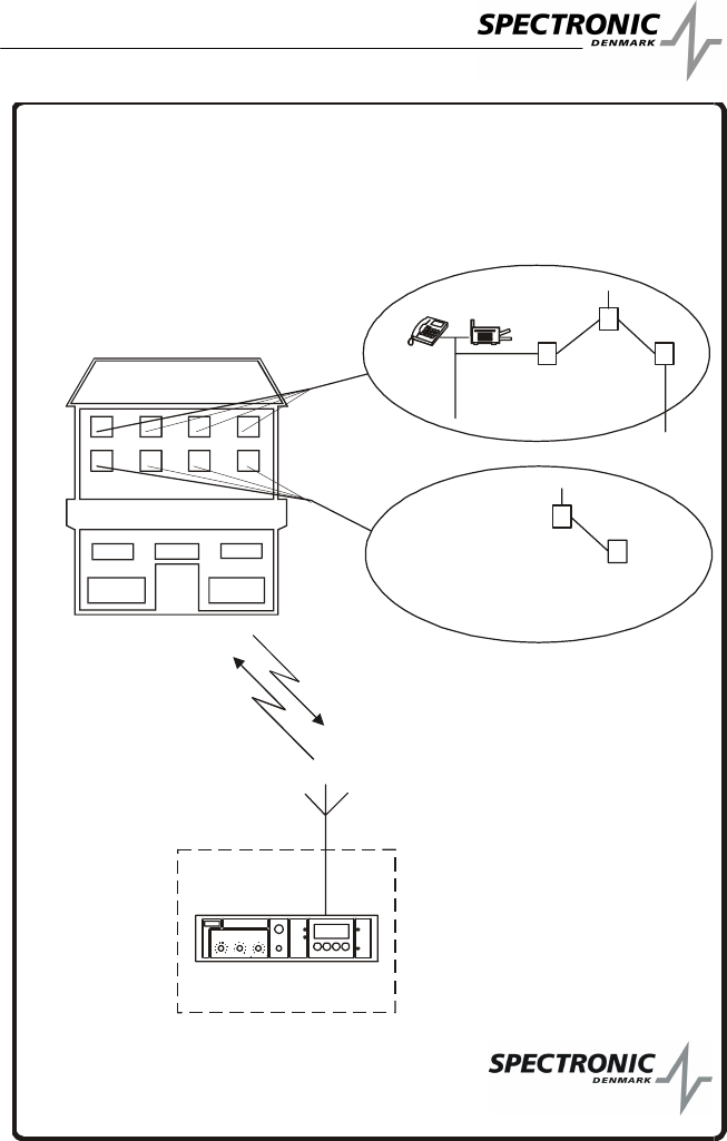
INCA SYSTEM
Target location
Listening post Audio rec.
OPERATIONAL SET-UP
INCA
TXM
PSTN
0.4
0.8
1.2
1.6
2.0 2.4
2.8
3.2
3.6
4.0 0.1
0.2
0.5
1.0
2.0
4.0
8.0
10 15
10
7
4
0
15
10
7
4
QFkHzdB
PARAMETRICEQUALIZER
AUDIO VOX
PHONES
GAIN SET DATA ENTRY
LEVEL
REL AY
SPEC TRONI C D ENM ARK
INCA
RSSI
POWER
P
O
W
E
R
Tar g et
signal
Remote
control
Main
115/230
INCA
PCI
INCA
MMM
Page 9 of 48
COMPANY CONFIDENTIAL
Wireless Audio and PSTN Monitoring System INCA
2.1 General
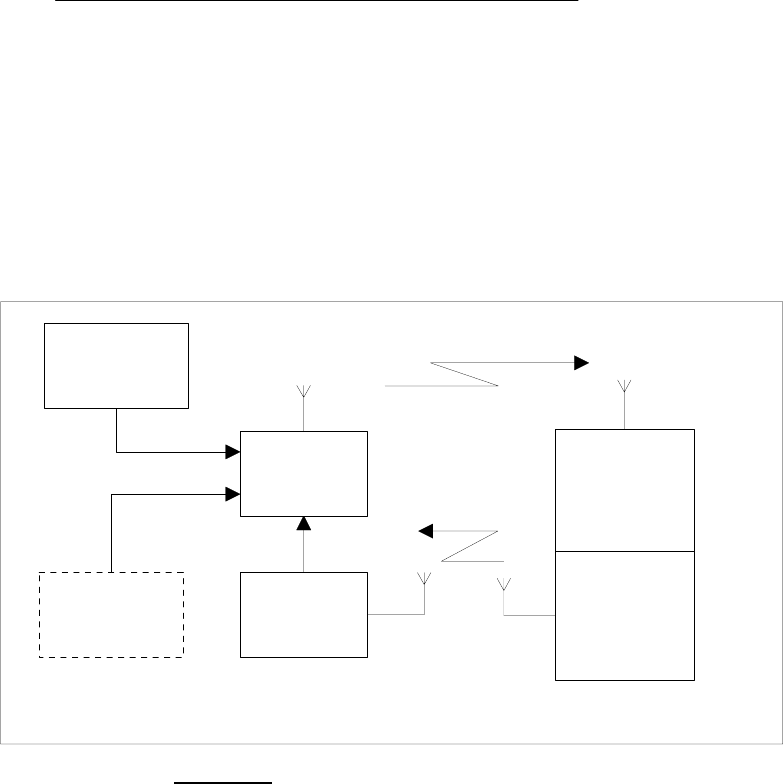
The INCA system is an advanced wireless remote controllable
transmitter/receiver set. The transmitter consists of a micro SMD
pieced module together with a remote - control module.
The receiver is a high sensitive PLL double conversion tuner and
contains a powerful remote - control transmitter.
2.2 The system
Remote -
transmitter
6
320 - 330 Mhz
433.92 Mhz
Transmitter
1
Remote -
receiver
2
115/230V
Power supply
3
3.3- 6.5V
Lithium
7
Receiver
5
FIGURE 1 Block diagram for the system

Page 10 of 48
COMPANY CONFIDENTIAL
Wireless Audio and PSTN Monitoring System INCA
2.3 The transmitter system
The transmitter system consists of 3 modules. A transmitter module
(1) which can be used as a stand-alone transmitter, a remote - control
module (2). The system is powered either from a
4 - 6V battery (7) or from the mains via a small switch - mode power
supply (3). The modules (1) and (2) measure approx
. 8.5 x 13 x 38 mm and module (3) 12 x 18 x 35 mm. The modules are
equipped with small connectors and are connected to each other by
means of flexible wires. That means that you can choose to install the
whole unit as a long “train” or folded together as a compact block.
2.4 Transmitter
The transmitter is very small that makes it is easy to conceal and is
built of high quality miniature SMD components to obtain a high
degree of reliability. It consists of a high sensitivity microphone with
low vibration sensitivity succeeded by an AGC-amplifier that is feeding
the FM modulation and output circuits. The AGC action of the amplifier
prevents over modulation at high sound levels and in the same time
makes it possible to listen to very weak conversation.
The transmitter is based on a crystal controlled PLL oscillator.
The output power is in the range from (5-30) mW depending on the
chosen power supply. With the 30 mW output power the cover range
will be app. 1000 meters at free sight and down to 50 - 100 meters in
concrete buildings. For maximum battery lifetime and for minimising
the risk to be found by “bug detectors” or “scanners” the transmitter
can be switched off into “sleep - mode by means of the remote
control. During the off state the transmitter is totally switched off, and
as the remote receiver does not contain a local oscillator as would
normally be the case, when using a heterodyne receiver, everything is
totally quiet.
Also for minimum current consumption, analogue frequency
modulation with an audio bandwidth of (300 - 5000) Hz has been
chosen.
The scrambler, which has been added for greater security and to avoid
listening in by unauthorised persons, can be switched on and off by
means of a jumper. It is based on simple frequency - inversion
technique due to the very low power needed for that sort of circuitry.

Page 11 of 48
COMPANY CONFIDENTIAL
Wireless Audio and PSTN Monitoring System INCA
In the scramble mode the audio frequency response as well as the
signal to noise ratio are somewhat degraded compared to the
unscrambled mode.
2.5 Remote receiver / transmitter
The remote - receiver module RCM is designed with a very small and
sensitive hybrid IC for unlicensed low-power remote control.
The system uses on-off keyed (OOK) modulation from a
microcontroller IC. Thus the The X-IDER remote control system can
be programmed with 4096 codes and with 8 factory pre-set into the
INCA receiver.
Normally such a system has a very limited coverage range due to the
limited output power dictated from regulations. Therefore the output
power from the remote transmitter, which is build in the main receiver,
has been “boosted” up to approx. 3 W., which will give a cover range
farbeyondthatofthemainsystem.Infreeairtheremotecontrolwill
reach up to 1 km. But inside buildings the range will be much shorter
depending on the local conditions. The remote receiver module
measures approx. 8.5 x 13 x 38 mm.
2.6 Power supply
The transmitter is powered by a 3.6 – 6.5V battery depending on the
required output power, alternatively from a small 115/230V AC mains
power supply which measures approx. 12 x 18 x 35 mm. The output
voltage is 5.75 V DC, 0.4 W max. and the mains voltage can be either
115 or 230 V AC 50/60 Hz (must be specified!). This power supply is a
unique switch-mode construction with sinusoidal voltages and
currents. This will greatly reduce the radiation of unwanted harmonics
and spurious frequencies and omit the need for bulky EMC filters and
metal screening.
Although the power supply is mains isolated to withstand a
voltage of 500 VAC it is not able to fulfil international safety
regulations. Therefore the power supply should only be used in
professional applications and is not intended for commercial use.
2.7 Receiver
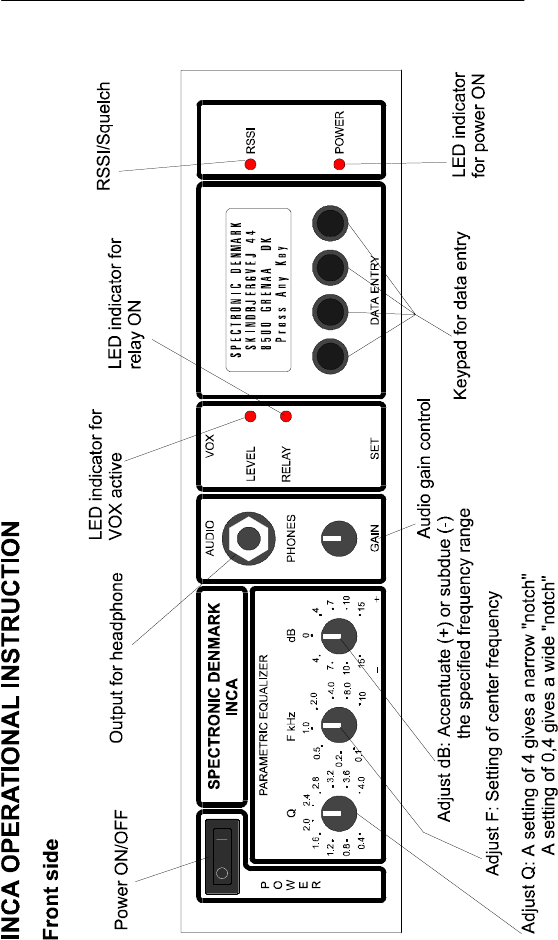
The receiver consists of a double conversion PLL tuner with very high
sensitivity. The tuner functions are controlled by means of a
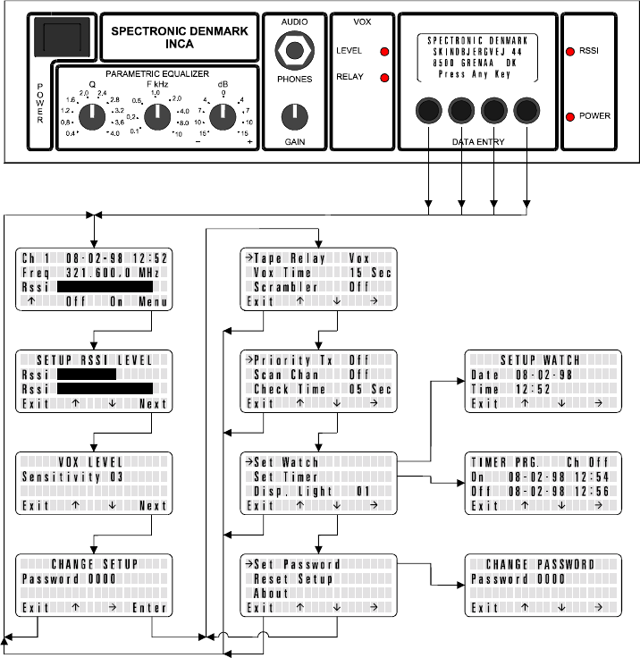
microcontroller via a LCD - display and 4 push buttons on the front.

Page 12 of 48
COMPANY CONFIDENTIAL
Wireless Audio and PSTN Monitoring System INCA
Underneath the display is placed the 4 push buttons by means of
which the different functions and set-ups of the receiver can be
controlled. The display will show the chosen channel number, one of
eight possible channels. Besides you will se the status of the four
channels, whenever they are active or not, which also can be
monitored on a RSSI bar - graph display.
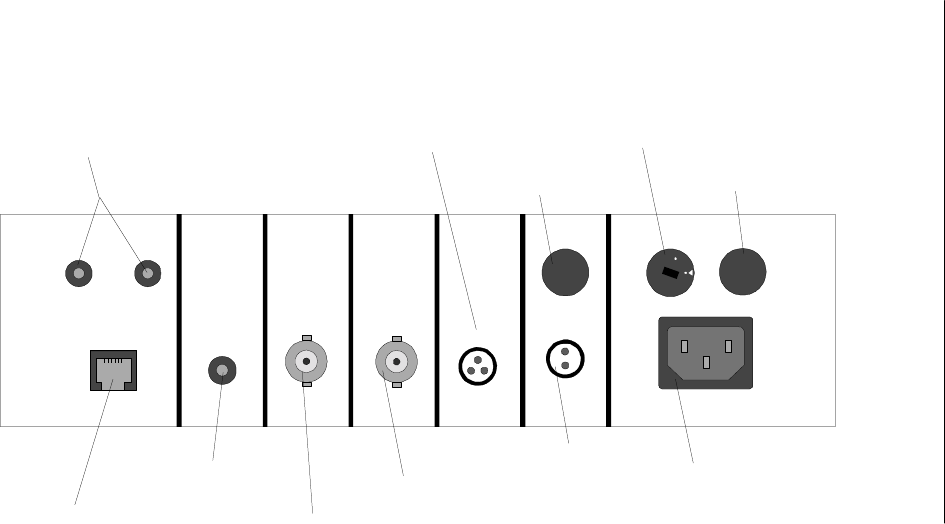
On the back of the receiver there are two antenna BNC - connectors;
one for RF input and one for remote power output, since the remote
transmitter is within the same cabinet as the receiver. You also have a
switch to bypass the build in de-scrambler, in case you have chosen
an unscrambled transmitter.
You will also find a relay output to switch a tape or a DAT recorder.
The relay is controlled either by a VOX (voice operated switch) circuit
or the RSSI level. This VOX is an advanced type of circuit that has the
ability to distinguish a voice from the background noise and trigger the
switch output circuit only by the voice signal. Therefore, the switching
operation is highly reliable in noisy environments. The sensitivity of the
switch as well as the switch-off delay of the VOX relay can also be
programmed from the front by means of the pushbuttons. The activity
of the VOX circuit as well as the function of the relay can be seen on
LED's on the front panel. The VOX relay has an adjustable switch-off
delay to avoid to many stops in the recordings during pauses in the
conversation.
There are 2 audio outputs; one line output with phono socket and a
telephone output with both 4-mm panel sockets and a standard
telephone connector. The telephone has a standard 600 ohm output
impedance and is equipped with an isolation transformer.
The audio signal is passed through a parametric equalizer that has a
variable 12dB boost or cut in the frequency range from 100 Hz to 10
kHz as well as a variable Q (the reverse of the relative bandwidth of
the boost or cut). By means of this equalizer it is possible to obtain
much better audio quality in noisy environments. The receiver has a
built-in loudspeaker that is automatically switched off when the
headphone jack is connected to the socket.
The receiver is powered from main 115/230 V AC, alternatively from
12 -15 V DC.
Page 13 of 48
COMPANY CONFIDENTIAL
Wireless Audio and PSTN Monitoring System INCA
Page 14 of 48
COMPANY CONFIDENTIAL
Wireless Audio and PSTN Monitoring System INCA
220
110
OUTPUT
LINE
TA P E
LINE OUT ANTENNA 1ANTENNA 2
RELAY OUT DC IN
FUSE
M AX. 48V /1A 12 VDC
2A
115/230VAC IN PUT
V
O
L
T
A
G
E
S
E
L
E
C
T
O
R
F
U
S
E
2
5
0
m
A
INCA OPERATIONAL INSTRUCTION
Rear side
Antenna 2:
Signal to remote control (Thin antenna)
Antenna 1:
Signal from TX (Thick antenna)
600 Ohm output for
phone line
phono connector
Output for audio
tape recorder
Mains connector
Input ext. DC
600 Ohm output for phone
line, screw terminals
Relay output for
control of tape recorder
Input ext. DC
115/230 Volt selector
250 mA system fuse
INCA OPERATIONAL
INSTRUCTION

Page 16 of 48
COMPANY CONFIDENTIAL
Wireless Audio and PSTN Monitoring System INCA
3 Technical Specifications
Receiver
Tuner
Frequency range 1 (standard) (320 - 330) MHz
Frequency range 2 (160 - 170) MHz
Sensitivity (fmod. = 1kHz, deviation ±3kHz,
20 dB SINAD) -113 dBm (0.5 uV)
Channel raster 12.5 kHz
Minimum channel spacing 25 kHz
Audio modulation FM
Frequency response (input to line out) 220 Hz - 6 kHz - 3dB
AM rejection (Vin=- 50 dBm, AMmod=30 %) 45 dB
Distortion
(Vin = - 50 dBm, deviation = ±3 kHz) < 2 %, 1kHz
Input impedance 50 ohm
Audio frequency response - 3dB (line out) 220 Hz to 6 kHz
Output voltage line out (deviation= ±3 kHz) 700 mV (no load)
Output voltage tlf. out (deviation= ±3kHz) 230 mV (600 ohm load)
Output impedance tlf. Out 600 ohm
Output impedance line out 1 kohm
Output impedance headphones out 47 ohm
Parametric equalizer frequency
adjustment range 100 Hz to 10 kHz
Parametric equalizer gain adjustment range ±12 dB
Parametric equalizer Q adjustment range 0.4 to 4
RF level meter range (-120 to -60) dBm
Remote transmitter
Remote control frequency1 (standard) 433.92 MHz
Output power into 50 ohm > 2.5 W
Modulation OOK
Coding addresses 4096
General

Page 17 of 48
COMPANY CONFIDENTIAL
Wireless Audio and PSTN Monitoring System INCA
Power supply mains feed 115/230V AC (50/60 Hz)
Power supply external DC input 12 - 15 V DC
Current consumption external DC input < 200 mA 12 V DC
Dimensions 265 x 260 x 82 mm
10.4 x 10.2 x 3.2 inches
Weight 2.8 kg / 6.17 lbs.
Transmitter module
Output frequency range 1 (standard) (320 - 330) MHz
Output frequency range 2 (160 - 170) MHz
Number of channels in the frequency range max. 8
Minimum channel spacing 25 kHz
Channel raster 12.5 kHz
Output impedance 50 ohm
Output power into 50 ohm (Vbatt. = 6V) 30 mW min.
Max. Modulation (FM) ±3kHz
Frequency response unscrambled 100 Hz to 10 kHz - 3 dB
Frequency response scrambled 280 Hz to 4 kHz - 3 dB
Audio amplifier AGC range 50 dB
Microphone vibration sensitivity: < 66 dB
Current consumption, active (Vbatt. = 6V) 300 mA DC typ.
Current consump., sleep mode (Vbatt. = 6V) <2 uA DC
Supply voltage (3.3 – 6.5) V DC
Dimensions 38 x 13.5 x 8.5 mm
1.5 x 0.5 x 0.3 inches
Remote control module
Remote control frequency1 433.92 MHz
Sensitivity - 100 dBm typ.
Modulation OOK
Coding addresses 4096
Power supply (3.3 – 6.5) V DC
Current consumption < 20 uA DC
Dimensions 38 x 13.5 x 8.5 mm
1.5 x 0.5 x 0.3 inches
Power supply 6 VDC / 0.4 W
Mains voltage 115/230 V AC
Primary current at max. load 6 mA AC

Page 18 of 48
COMPANY CONFIDENTIAL
Wireless Audio and PSTN Monitoring System INCA
Output voltage 5.75 V DC
Output current 75 mA max.
Dimensions 38 x 18 x 12 mm
1.5 x 0.7 x 0.5 inches
Transmitter system
Total current consumption, switched off <20 uA DC
Total current consumption, switched on 60 mA DC typ.
Overall unscrambled frequency response
(transmitter - receiver) 250 Hz - 6 kHz
Overall scrambled frequency response
(transmitter - receiver) 350 Hz - 4 kHz

Page 19 of 48
COMPANY CONFIDENTIAL
Wireless Audio and PSTN Monitoring System INCA
3.1 Test results for X-IDER 4096
With new Duracell Alkaline 9V MN1604-6LR61
Transmitting power (Watt) No. of transmissions Battery power by
last transmission (VDC)
Over 2.00 45 7.8
1.75 – 2.00 25 7.5
1.50 – 1.75 25 7.3
1.25 – 1.50 42 7.0
1.00 – 1.25 57 6.85
0.9 – 1.00 140 6.7
0.8 – 0.9 137 6.6 Battery LOW
starts and stops.
0.7 – 0.8 93 6.5
0.6 – 0.7 85 6.4 Battery LOW
on every time.
0.5 – 0.6 110 6.3
0.4 – 0.5 90 6.2
It is to be expected that the XIDER 4096 TX unit should be able to perform about 100
transmissions with a good distance by using a new good quality battery.
Page 21 of 48
COMPANY CONFIDENTIAL
Wireless Audio and PSTN Monitoring System INCA
INCA SYSTEM
Listening post
Multi target/large scale configuration
0.4
0.8
1.2
1.6
2.0 2. 4
2.8
3.2
3.6
4.0 0.1
0.2
0.5
1.0 2.0
4.0
8.0
10 15
10
7
4
0
15
10
7
4
QFkHz dB
PA RAM ETR IC EQ U A LIZE R
AUDIO VOX
PHONES
GAIN SET DATAENTRY
LEVEL
RELAY
SPECTRONIC DENMARK
INC A
RSSI
POWER
P
O
W
E
R
HOTEL
INCA
TXM
INCA transmit
module TXM
INCA remote
module RCM
PSTN
Main
110/240

Page 22 of 48
COMPANY CONFIDENTIAL
Wireless Audio and PSTN Monitoring System INCA
4 Parts List INCA Basic Configuration 1
Pcs Description
1 INCA RX
1 INCA TXM Opt. 003 channel 1 + INCA RCM Opt 004
1 Antenna 1, telescope
1 Antenna 2, 70 cm band
1 Headphone
1 Elbow BNC connector
1 Extra fuse 250 mA
1 Extra fuse 2 A
1Powercord
1 Cable for relay (Lemo to open end)
1 INCA User Guide
1 Suitcase
2Keys

Page 23 of 48
COMPANY CONFIDENTIAL
Wireless Audio and PSTN Monitoring System INCA
5 Parts List INCA Basic Configuration 2
Pcs Description
1 INCA RX
1 INCA TXM Opt. 003 channel 1 + INCA RCM Opt 004
1 INCA TXM Opt. 003 channel 2 + INCA RCM Opt 004
1 INCA TXM Opt. 003 channel 3 + INCA RCM Opt. 004
1 INCA TXM Opt. 003 channel 4 + INCA RCM Opt. 004
1 Antenna 1, telescope
1 Antenna 2, 70 cm band
1 Headphone
1 Elbow BNC connector
1 Extra fuse 250 mA
1 Extra fuse 2 A
1Powercord
1 Cable for relay (Lemo to open end)
1 INCA User Guide
1 Suitcase
2Keys

Page 24 of 48
COMPANY CONFIDENTIAL
Wireless Audio and PSTN Monitoring System INCA
6 Parts List INCA Basic Configuration 3
Pcs Description
1 INCA RX
1 INCA TXM Opt. 003 channel 1 + INCA RCM Opt 004
1 INCA TXM Opt. 003 channel 2 + INCA RCM Opt 004
1 INCA TXM Opt. 003 channel 3 + INCA RCM Opt. 004
1 INCA TXM Opt. 003 channel 4 + INCA RCM Opt. 004
1 INCA TXM Opt. 003 channel 5 + INCA RCM Opt 004
1 INCA TXM Opt. 003 channel 6 + INCA RCM Opt 004
1 INCA TXM Opt. 003 channel 7 + INCA RCM Opt. 004
1 INCA TXM Opt. 003 channel 8 + INCA RCM Opt 004
1 Antenna 1, telescope
1 Antenna 2, 70 cm band
1 Headphone
1 Elbow BNC connector
1 Extra fuse 250 mA
1 Extra fuse 2 A
1Powercord
1 Cable for relay (Lemo to open end)
1 LEMO plug 2-pol for DC IN
1 INCA User Guide
1 Suitcase
2Keys

Page 25 of 48
COMPANY CONFIDENTIAL
Wireless Audio and PSTN Monitoring System INCA
7 Parts List INCA Options
Pcs Description
INCA TXM Opt. 003 channel 1
INCA TXM Opt. 003 channel 2
INCA TXM Opt. 003 channel 3
INCA TXM Opt. 003 channel 4
INCA TXH Opt. 008 channel 1
INCA TXH Opt. 008 channel 2
INCA TXH Opt. 008 channel 3
INCA TXH Opt. 008 channel 4
INCA RCM Opt. 004
INCA SXM Opt. 005
INCAPCIOpt.006
INCA MMM Opt. 007
8 INCA TX/RC PSTN Wireless Telephone Line
Transmitter

Page 26 of 48
COMPANY CONFIDENTIAL
Wireless Audio and PSTN Monitoring System INCA
8.1 Introduction
This document describes the general functions and performance of the
Spectronic INCA TX/RC PSTN wireless telephone line transmitter.
Information on the items of a specific delivery is to be found in a
separate document, stating TX frequency and remote control address
codes of the individual units.
Note: The special functions/upcodes will only be available, if using an
X-IDER TX. Please refer to “Remote Control Upcodes 8.2.6” page 30.
8.2 System Concept
8.2.1 General
The INCA TX/RC PSTN is a series of wireless, remote controllable,
minimum size VHF or UHF transmitters intended for concealed room
monitoring connected in parallel to a PSTN telephone line. The input
impedance is very high, so the loading of the telephone line will be
negligible. The transmitters can be switched into a “sleep-mode” by
means of the wireless remote control X-IDER transmitter. In this
“sleep-mode” the current consumption is only app. 35 uA, which will
maximize the lifetime of the battery. Alternatively, at the expense of a
little higher current consumption (approx. 90 uA), the transmitter can
be switched into an OFF-HOOK mode. In this state the transmitter is
only running when the DC off-hook level of the telephone line is
below a predetermined value. This OFF-HOOK circuit has three
different selectable remote control turn-on levels, which are
respectively 10V, 20V and 40V DC line voltage.
The transmitter also includes audio scrambler-circuit, which can be
switched on and off by the remote control, just like the OFF-HOOK
circuit and the sleep-mode state. The TX unit comes with flying leads
for battery connection, telephone line connection and for remote RX
antenna, whereas the TX antenna terminal has a female MMCX-
connector. The TX unit is deliverable with either internal or external
microphone.
8.2.2 Application Note
When an antenna is in close proximity to metal surfaces, concrete
walls or the human body, the efficiency of the transmitter will be
Page 27 of 48
COMPANY CONFIDENTIAL
Wireless Audio and PSTN Monitoring System INCA
minimized due to power absorption and disturbance of the antenna
radiation pattern. To achieve
maximum RF range, it is therefore advisable to keep the antenna so
far away from the surroundings as possible. If you let the TX run
continuously, your operational time will be degraded seriously. When
no monitoring is wanted or you know for sure that the target person
will not be present for a certain period, it is therefore advisable to
switch off the transmitter via the X-IDER remote-control transmitter to
preserve the battery. Alternatively, you simply choose OFF-HOOK
mode, in which case the TX only will “go in the air” every time the
phone is going off-hook.
Although the transmitter will work excellently with most standard
receivers or scanners, provided they have the right audio de-
emphasis, you will get the best results by using the Spectronic INCA
receiver. Most standard receivers and scanners have an audio
bandwidth of 300-3000 Hz, whereas the INCA receiver has a
bandwidth from 300-4000 Hz, even in scramble mode. Investigations
at Spectronic have shown that the audio intelligibility is improved
substantially by increasing the upper audio band limit from 3000 Hz
to 4000 Hz. The INCA receiver also has superior selectivity and
sensitivity, which will give the best possible RF range.
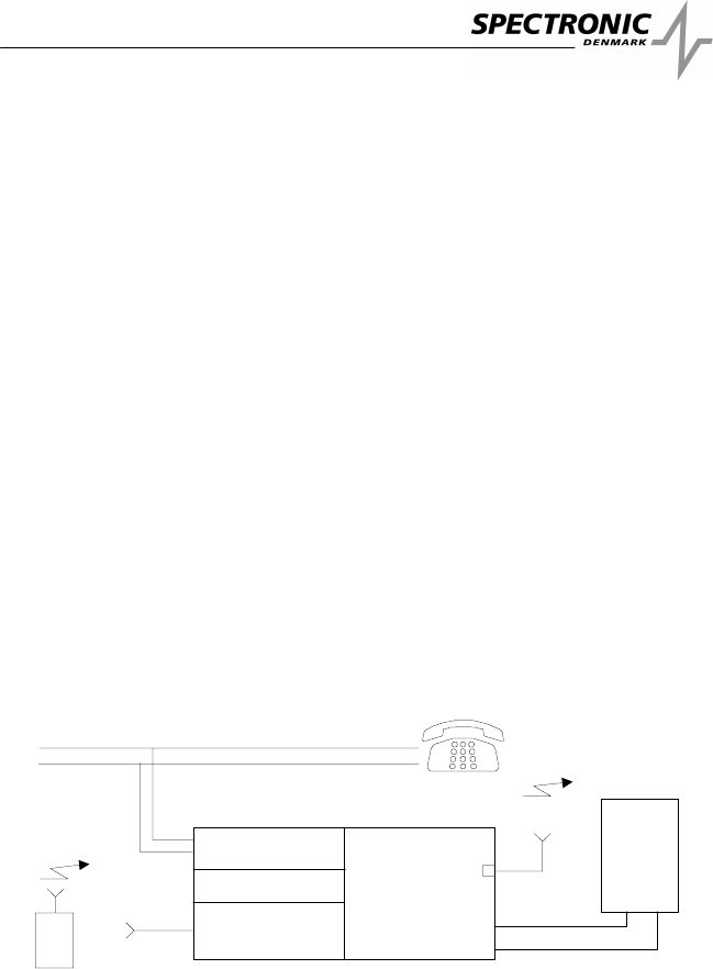
8.2.3 Block Schematic
RC-receiver
Audio-AGC
TX-part
TX antenna
RC-antenna
X-ider TX
B
attery or
mains
module
(MMM)
TX-RC -PSTN
Scrambler
Ph o n e
Ph o n e l i n e
8.2.4 Transmitter
The transmitter is made of high quality miniature SMD components
to obtain a high degree of reliability. Since is very small, it is easy to

Page 28 of 48
COMPANY CONFIDENTIAL
Wireless Audio and PSTN Monitoring System INCA
conceal. It consists of an AGC-amplifier that feeds both the
scrambler, the FM modulation and the output circuits. The AGC
action of the amplifier prevents over-modulation at high sound levels
and makes it possible to listen to very weak conversation at the
same time.
The transmitter is based on a crystal controlled PLL-synthesized
oscillator. The frequency can be chosen in the range (320-330) MHz
or (155-173) MHz.
For maximum battery lifetime and for minimizing the risk of being
found by “bug detectors” or “scanners” the transmitter can be
switched off into “sleep-mode” by means of the remote control.
Alternatively the transmitter can be switched off into a “OFF-HOOK
mode” with the same advantages. In the “sleep-mode” the receiver
only goes in the air in approx. 30 msec. for every 2.5 seconds to look
for a valid code transmission
During off state, the transmitter is completely switched off. Since the
remote receiver does not contain a local oscillator as would normally
be the case when using a heterodyne receiver, everything is totally
quiet and nothing can be traced by e.g. spectrum analyzers or
scanners.
For minimum current consumption, analogue frequency modulation
with an audio bandwidth of (280 - 5000) Hz (unscrambled mode) has
been chosen.
The scrambler, which can be switched on and off by means of the
remote control, has been added for greater security and to avoid
listening-in by unauthorized persons. It is based on simple
frequency-inversion techniques due to the very low power needed for
that sort of circuit. In the scramble mode, the audio frequency
response, as well as the signal to noise ratio, are somewhat
minimized compared to the unscrambled mode.
8.2.5 Remote Control Receiver
The remote-receiver is realized by a very small and sensitive hybrid
IC, intended for unlicensed low-power remote control. The carrier
frequency is OOK (on off keyed) modulated and the system provides
up to 4096 different address codes. The Spectronic X-IDER remote-
control transmitter is used to send different codes for setting up the
TX. By reception of a new upcode, the TX will send an acknowledge

Page 29 of 48
COMPANY CONFIDENTIAL
Wireless Audio and PSTN Monitoring System INCA
signal by toggling the RF on and off in three cycles of 0.6 Sec.
duration.
The Address Code of the Remote Control will be Factory set,
according to customer specifications or as specified for standard
frequencies by Spectronic.

Page 30 of 48
COMPANY CONFIDENTIAL
Wireless Audio and PSTN Monitoring System INCA
8.2.6 Remote Control Upcodes
X-IDER left-hand HEX switch
0TXon
1 TX off (factory default)
4 TX audio scrambler on
5 TX audio scrambler off (factory default)
A TX OOF-HOOK defeated (factory default)
B TX with OFF-HOOK control, line voltage = 10V DC
C TX with OFF-HOOK control, line voltage = 20V DC
D TX with OFF-HOOK control, line voltage = 40V DC
E Start up state after DC removal: TXoff
F Start up state after DC removal: Same as before DC
removal (factory default)

Page 31 of 48
COMPANY CONFIDENTIAL
Wireless Audio and PSTN Monitoring System INCA
8.3 Technical Specifications
Transmitter
Output frequency range UHF (standard) (320 - 330) MHz
Output frequency range VHF (155 - 173) MHz
Operational temperature range 0°-+50°C / 32F – 122F
Frequency stability (above temp. range) ±5 ppm
Minimum channel spacing 25 kHz
Channel raster 12.5 kHz
Output impedance 50 Ω
Max. Modulation: (FM) ±4kHz
Audio frequency response unscrambled 100 Hz to 5 kHz - 3 dB
Audio frequency response scrambled 280 Hz to 4 kHz - 3 dB
Audio pre-emphasis 6dB/Octave
Audio amplifier AGC range 50 dB
Current consumption, active (Vbatt. = 6V) <70 mA DC
Current consumption, sleep-mode < 40 uA DC
Current consumption, OFF-HOOK
(PhoneON-HOOK) <100uADC
Output power (Vbatt. = 6V) >50 mW @ 50 Ω
DC line input impedance >10 Meg Ω
AC line input impedance >100 k Ω
Receiver
Remote control frequency 433.92 MHz
Sensitivity < - 90 dBm
Modulation OOK
Coding addresses 4096
9. INCA TX/RC VOX Wireless Transmitter

Page 32 of 48
COMPANY CONFIDENTIAL
Wireless Audio and PSTN Monitoring System INCA
9.1 Introduction
This document describes the general functions and performance of the
Spectronic INCA TX/RC VOX transmitter.
Information on items of a specific delivery is to be found in a separate
document, stating TX frequencies and remote control address codes of the
individual units.
Note: The special functions/upcodes will only be available, if using an
X-IDER TX. Please refer to “Remote Control Upcodes 9.2.6” page 36.
9.2 System Concept
9.2.1 General
The INCA TX/RC VOX is a series of wireless, remote controllable,
minimum size VHF or UHF transmitters intended for concealed room
monitoring or as body transmitters. The transmitters can be switched
into “sleep-mode” by means of the wireless remote control X-IDER
transmitter. In this “sleep-mode” the current consumption is only app.
35 uA, which maximizes the lifetime of the battery. Alternatively, at
the expense of a little higher current consumption (app. 90 uA), the
transmitter can be switched into VOX-mode, meaning that the
transmitter will run only when the microphone hear acoustic signals
like talking or music.
This VOX is an advanced type of circuit that has the ability to
distinguish voice from background noise and the power circuit is
only switched on when a voice signal is present. Therefore, the
switching operation is highly reliable in noisy environments. The
VOX-circuit has three different, selectable remote control turn-on
levels, which are respectively 2, 5 and 10 dB above background
noise level.
The transmitter also includes audio scrambler-circuit, which can be
switched on and off by the remote control, just like the VOX-circuit
and the sleep-mode state. The TX unit comes with flying leads for
both battery connection and remote RX antenna, whereas the TX
antenna terminal has a female MMCX-connector. The TX unit is
deliverable with either internal or external microphone.

Page 33 of 48
COMPANY CONFIDENTIAL
Wireless Audio and PSTN Monitoring System INCA
9.2.2 Application Note
When an antenna is in close proximity to metal surfaces, concrete
walls or the human body, the efficiency of the transmitter will be
minimized due to power absorption and disturbance of the antenna
radiation pattern. To achieve
maximum RF range it is therefore advisable to keep the antenna as
far away from the surroundings as possible. If you let the TX run
continuously, your operational time will be minimized seriously.
When no monitoring is wanted or you know for sure that no persons
will be present in the room for a certain period, it is advisable to
switch off the transmitter via the X-IDER remote-control transmitter to
preserve the battery. Alternatively, simply choose VOX mode, when
in doubt whether persons will be present in the room being
monitored. The TX will then only go “on the air” every time
conversation is detected in the room. After app. 15 sec. without
conversation, the TX will go to sleep again and thus sawing battery
power.
Although the transmitter will work excellent with most standard
receivers or scanners, provided they have the right audio de-
emphasis, you will get the best results by using the Spectronic INCA
receiver. Most standard receivers and scanners have an audio
bandwidth of 300-3000 Hz, whereas the INCA receiver has a
bandwidth from 300-4000 Hz, even in scramble mode. Investigations
at Spectronic have shown that the audio intelligibility is improved
substantially by increasing the upper audio band limit from 3000 Hz
to 4000 Hz. The INCA receiver also has a superior selectivity and
sensitivity, which will give the best possible RF range.
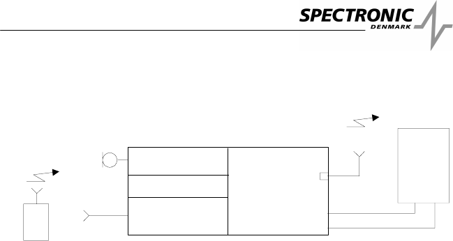
9.2.3 Block Schematic
Page 34 of 48
COMPANY CONFIDENTIAL
Wireless Audio and PSTN Monitoring System INCA
RC-receiver
Audio-AGC
TX-part
TX antenna
RC-antenna
X-ider TX
Mic Battery or
mains
module
(MMM)
TX-RC -VOX
Scrambler
9.2.4 Transmitter
The transmitter is made of high quality miniature SMD components
to obtain a high degree of reliability. Since it is very small, it is easy
to conceal. It consists of a highly sensitive microphone with low
vibration sensitivity succeeded by an AGC-amplifier that feeds both
the scrambler, the FM modulation and the output circuits. The AGC
action of the amplifier prevents over-modulation at high sound levels
and makes it possible to listen to very weak conversation at the
same time.
The transmitter is based on a crystal controlled PLL-synthesized
oscillator. The frequency can be chosen in the range (320-330) MHz
or (155-173) MHz.
For maximum battery lifetime and for minimizing the risk of being
found by “bug detectors” or “scanners”, the transmitter can be
switched off into “sleep-mode” by means of the remote control.
Alternatively the transmitter can be switched off into “VOX-mode”
with the same advantages. In “sleep-mode” the receiver only goes
on the air in app. 30 msec. for every 2.5 seconds to look for a valid
code transmission
During off state, the transmitter is completely switched off, and as the
remote receiver does not contain a local oscillator as would normally
be the case, when using a heterodyne receiver, everything is totally
quiet and nothing can be found by e.g. spectrum analyzers or
scanners.

Page 35 of 48
COMPANY CONFIDENTIAL
Wireless Audio and PSTN Monitoring System INCA
For minimum current consumption, analogue frequency modulation
with an audio bandwidth of (280 - 5000) Hz (unscrambled mode) has
been chosen.
The scrambler, which can be switched on and off by means of the
remote control, has been added for greater security and to avoid
listening-in by unauthorised persons. It is based on simple
frequency-inversion techniques due to the very low power needed for
that sort of circuit. In the scramble mode, the audio frequency
response, as well as the signal to noise ratio, are somewhat
minimized compared to the unscrambled mode.
9.2.5 Remote Control Receiver
The remote-receiver is realized by a very small and sensitive hybrid
IC, intended for unlicensed low-power remote control. The carrier
frequency is OOK (on off keyed) modulated and the system provides
up to 4096 different address codes. The Spectronic X-IDER remote-
control transmitter is used to send the different codes for setting up
the TX. By reception of a new upcode the TX will send an
acknowledge signal by toggling the RF on and off in three cycles of
0.6 Sec. duration.
The Address Code of the Remote Control is Factory set, according
to customer specifications, or as specified for standard frequencies
by Spectronic.
9.2.6 Remote Control Upcodes
X-IDER left-hand HEX switch
0TXon
1 TX off (factory default)
4 TX audio scrambler on

Page 36 of 48
COMPANY CONFIDENTIAL
Wireless Audio and PSTN Monitoring System INCA
5 TX audio scrambler off (factory default)
A TX with VOX defeated (factory default)
B TX with VOX, level 2 dB above noise
C TX with VOX, level 5 dB above noise
D TX with VOX, level 10 dB above noise
E Start up state after DC removal: TX off
F Start up state after DC removal: Same as before DC
removal (factory default)
9.3 Technical Specifications
Transmitter
Output frequency range UHF (standard) (320 – 330) MHz
Output frequency range VHF (155 – 173) MHz
Operational temperature range 0°-+50°C / 32F – 122F
Frequency stability (above temp. range) ±5 ppm
Minimum channel spacing 25 kHz
Channel raster 12.5 kHz

Page 37 of 48
COMPANY CONFIDENTIAL
Wireless Audio and PSTN Monitoring System INCA
Output impedance 50 Ω
Max. Modulation (FM) ±4kHz
Audio frequency response unscrambled 100 Hz to 5 kHz – 3 dB
Audio frequency response scrambled 280 Hz to 4 kHz – 3 dB
Audio pre-emphasis 6dB/Octave
Audio amplifier AGC range 50 dB
Microphone vibration sensitivity < 66 dB
Current consumption, active (Vbatt. = 6V) <70 mA DC
Current consumption, sleep-mode < 40 uA DC
Current consumption, VOX-mode (silent room) < 100 uA DC
Output power (Vbatt. = 6V) >50 mW @ 50 Ω
Size 33 x 24 x 7 mm
1.3 x 0.9 x 0.3 inches
Receiver
Remote control frequency 433.92 MHz
Sensitivity < - 90 dBm
Modulation OOK
Coding addresses 4096
