Spectrum Technologies SP911 Access Point User Manual users manual
Spectrum Technologies Corporation Access Point users manual
users manual

Quick Installation Guide
Access Point (AP)
Model No.: SP911
Website: http://www.micronet.com.tw
2
Federal Communications Commission Statement
This equipment has been tested and found to comply with the limits for a Class B
digital device, pursuant to part 15 of the FCC Rules. These limits are designed to
provide reasonable protection against harmful interference in a residential
installation. This equipment generates, uses and can radiate radio frequency energy
and, if not installed and used in accordance with the instructions, may cause harmful
interference to radio communications. However, there is no guarantee that
interference will not occur in a particular installation. If this equipment does cause
harmful interference to radio or television reception, which can be determined by
turning the equipment off and on, the user is encouraged to try to correct the
interference by one or more of the following measures:
— Reorient or relocate the receiving antenna.
— Increase the separation between the equipment and receiver.
— Connect the equipment into an outlet on a circuit different from that to which the
receiver is connected.
— Consult the dealer or an experienced radio/TV technician for help.
You are cautioned that changes or modifications not expressly approved by the
party responsible for compliance could void your authority to operate the equipment.
3
Introduction
Micronet SP911 Access Point is design to work with SP905 PCMCIA Adapter. Please insert SP905
into the back of SP911.
Package Content
SP911 Access Point x 1 Utility Disk or CD
AC Power Adapter x 1 Quick Installation Guide x 1
Front panel of the Access Point:
The following table provides an overview of each LED activity:
LED Activity Description
PWR Continuous Green Power enabled
AP Continuous Green The Access Point is ready in service.
Off: No activity
WLAN Flashing Green Flashing: RX/TX activity
Off: No Ethernet traffic activity
LAN Flashing Green Flashing: traffic activity
Off: no station connected to the Access Point
LINK Green On: with one or more stations connected to SP911
Table 1:LED of SP911 Front Panel
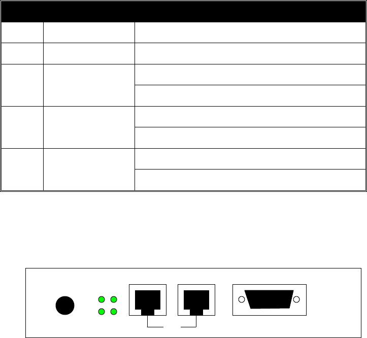
Back panel of the Access Point:
Figure 1:Back Panel of SP911
POWER MDI MDI-X RS-232
Link OR
RX
100M TX
4
Power Socket
The power adapter plugs into the socket labeled “POWER”.
Ethernet Ports
The Ethernet ports consist of RJ-45 MDI daisy-chain port (labeled “MDI”) and RJ-45 MDI-X station
port (labeled “MDI-X”). To connect the Access Point to a hub, use the MDI port; to connect the
Access Point to a computer/station, use the MDI-X port. Both connection ports are used with straight-
through UTP cable. Note that, these two RJ-45 ports cannot be used at the same time.
The four LEDs next to the Ethernet ports show the Ethernet physical link status. The ‘Link’ LED is a
good indicator for checking the correctness of Ethernet cable connection.
RS232 Port (Console Port)
The RS232 port is for configuring the Access Point. Use a null-modem RS232 cable when you desire
to configure the Access Point under console mode. See the section “Access Point Console” for detailed
information.
5
Installing the Access Point
Take the following steps to set up your Access Point.
! Site Selection
Use the Site Survey and Access Points Browser utility (The tool bundles with SP905 PC card) to
choose a proper placement for your Access Point. Typically, the best location to place your Access
Point at your site is the center of your coverage area, with line of sight to all your mobile stations.
! Connect the Ethernet Cable
The SP911 can be connected to the 10/100M Ethernet network. Connect your UTP Ethernet cable
to the RJ-45 connector of the Access Point. Specially note that, to connect the Access Point to a
hub, use the MDI port; to connect the Access Point to a computer/station, use the MDI-X port.
! Connect the Power Cable
Connect the power adapter cable to the power socket of SP911 and turn on the power. USE ONLY
the power adapter supplied with the Access Point. Otherwise, the product may be damaged.
Configuring the Access Point
SP911 Access Point is shipped with default parameters. Simply install the Access Point, power it on,
and it is ready to work. Nevertheless, you can still modify the parameters depending on your needs.
The SP911 can be configured either via the configuration utility (supplied), console mode connection,
or anywhere through TCP/IP (Telnet) connection.
Access Point Manager
Installed on your Windows 95/98/NT/2000 desktop computer, the Windows-based utility “Access Point
Manager” provides user-friendly interface, enabling you to make the configuration of all your Access
Points on the network more easily than ever before. The following outlines the installations of the
Access Point Manager utility.
1. Insert the utility disk into the floppy drive of your PC.
2. From the Start menu on the Windows desktop, choose Run.
3. In the Run dialog box, type a:\setup.exe, then click OK.
4. Follow the on-screen instructions to install the Access Point Manager.
5. Execute the Access Point Manager and it will browse all the Access Points available on the
network.
6
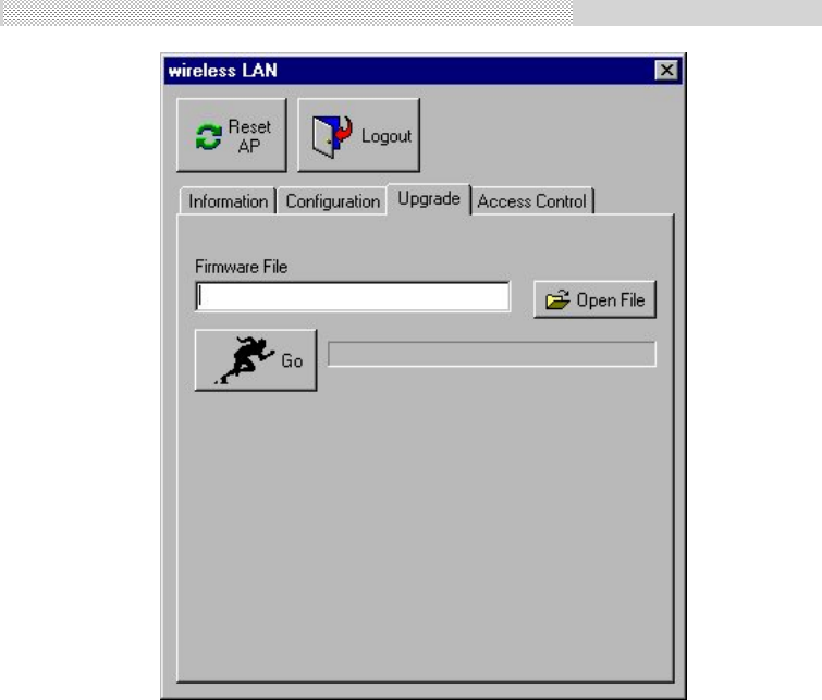
6. Double click to open an Access Point’s property dialog box to view/make the configuration as you
desire.
Note: the default password to get access to the Access Point is “default”.
Figure 2: Access Point Manager
Access Point Console
The Access Point can be configured via the command prompt console with either the RS232
connection or the Telnet (TCP/IP) connection.
" RS232 (serial) Connection: First-time users or users desiring to make changes in the default IP
address need to use the any terminal emulation program with a RS232 (serial) connection (e.g.,
Telix, ProCOMM, or Windows 95/98/NT/2000’s HyperTerminal). Use a null-modem cable to
configure the port settings: 57600 bps, 8 data bits, no parity, no flow control. An Access Point
console will pop up when the connection has been established.
" Telnet (TCP/IP) Connection: Assign an IP address for your Access Point through RS-232
connection first and then telnet to the Access Point anywhere to get access to the Access Point

7
console, then you will be able to make the configuration via the TCP/IP connection.
Note: the default password to get access to the Access Point is “default”.
The following are the commands provided for configuring the Access Point. In loader mode, i.e., no
valid firmware in the Access Point, only the commands with an asterisk (*) are provided.
Note: [xxx] stands for optional arguments.
info*
Display some basic information of the Access Point, for example, firmware version, frequency
domain, etc.
passwd
Change the password of the Access Point.
ping ip_addr [num_pings] [data_size]
Ping (ICMP echo) to an ip_addr host with optional num_pings times with optional data size in a
length of data_size.
save
Save your new configuration.
auth mode | add | del | list| clear | save|
The 'auth' command contains sub-commands that allow you to manage the access control (MAC
address filter) of the Access Point. The access control table consists of a list for you to control the
access of any stations or repeaters. The sub-commands are listed below:
mode open | allow: set the access control mode. The definition of each mode is indicated as
follows:
• open: open to public (default)
• allow: only allow access of the authorized stations/repeaters.
add mac_addr:
add an address into the access control table
del mac_addr |index:
remove an address, or index an address from the access control table
set
List the configuration information.
set default
Restore the default setting of the Access Point except for IP addresses. Take a note that a 'save'
command is required for changes to take effect.
set apname | channel | essid | rts_threshold | frag_threshold | ip_address | ip_netmask | ip_gateway
To change settings, type “set xxx (parameter) xxxx (value). For example, set channel 7 command
will set the channel to number 7; set essid “Your Network” command will set the ESSID as Your
Network. Remember that, a 'save' command is required for changes to take effect.

8
Parameter Description Default Value
apname A textual name for the identification of SP911. apXXXXXX
(where XXXXXX is
the last six octets of
SP911's MAC add.)
channel The radio channel number. 1
essid The ESS ID (a.k.a., SSID) of the Access Point. My Network
rts_threshold The threshold (bytes) for enabling RTS/CTS handshake.
Data with its frame size larger than this value will perform
the RTS/CTS handshake. Range of value: 0~2432.
2432
frag_threshold The threshold (bytes) for the fragmentation boundary. Data
will be transmitted in fragments which its size does not
exceed this value. Range of value: 256~2432.
2432
ip_address The IP address of SP911. 192.168.1.1
ip_netmask The subnet mask address of SP911. 255.255.255.0
ip_gateway The default gateway address of SP911. 192.168.1.254
Table 2: Parameter of Set command
list [start/end]:
display the content of the access control mode and the address list. The optional arguments, start
and end, can be affixed to select the range of items to be listed.
clear:
clear all the addresses in the access control table.
cls*
Clear the console screen.
exit*
Exit the console.
help*
Print a help screen.
rz*
Receive a firmware file by the Zmodem protocol. The console will enter Zmodem receiving mode
and then use the "file upload" function of your terminal emulation program to upload a new
firmware file (ap.img) to the Access Point. Upon completion, always remember to type the 'reset'
command for running the Access Point with the new firmware.
reset*
Issue a reset signal. The Access Point will be reset if user confirms.

9
Trouble Shooting for SP911
If you have trouble using the SP911 Access Point, the starting point to troubleshoot the problem with
your Access Point is looking at the LED activity of the Access Point, then checking the configuration
parameter settings of both the Access Point. The following is “LED Error Table” that can assist you in
diagnosing and solving operational problems.
PWR AP WLAN LAN LINK Description/Action
Steady
Green
Continuous
Green
Flash
Green
Flash
Green
-
Normal operation where flickering indicates
interface activity.
No action required.
Continuous
Green
On Off Off -Normal operation, indicates no LAN activity.
No action required.
Off Off Off Off Off
Power failure.
Check the power cord.
Check the power supply.
Off Off Off Off Invalid loader firmware or the micro-controller is
dead.
Blink Green - - -
Invalid Access Point firmware.
Upgrade the firmware via the console mode.
Blink Green Blink
Green --initialization failure
Continuous
Green
Blink Green - Blink
Green -Ethernet initialization failure
Table 3:LED Error Table of SP911
Technical Support
You can find the most recent software and user documentation on our Web site.
http://www.micronet.com.tw
If you have difficulty resolving the problem while installing or using the SP911,
please contact us at:
support@micronet.com.tw
P/N:50001-929110