SpiderCloud Wireless 8818C24 Universal Small Cell 8818 LTE/LTE Module User Manual Cisco USC 8718 8818 Installation Guide
SpiderCloud Wireless Universal Small Cell 8818 LTE/LTE Module Cisco USC 8718 8818 Installation Guide
UserManual.wiki
>
SpiderCloud Wireless
>
8818C24 User Manual
User Manual
Navigation menu
Upload a User Manual
Namespaces
Wiki Guide
HTML
PDF
Info
Views
User Manual
Discussion / Help
Navigation
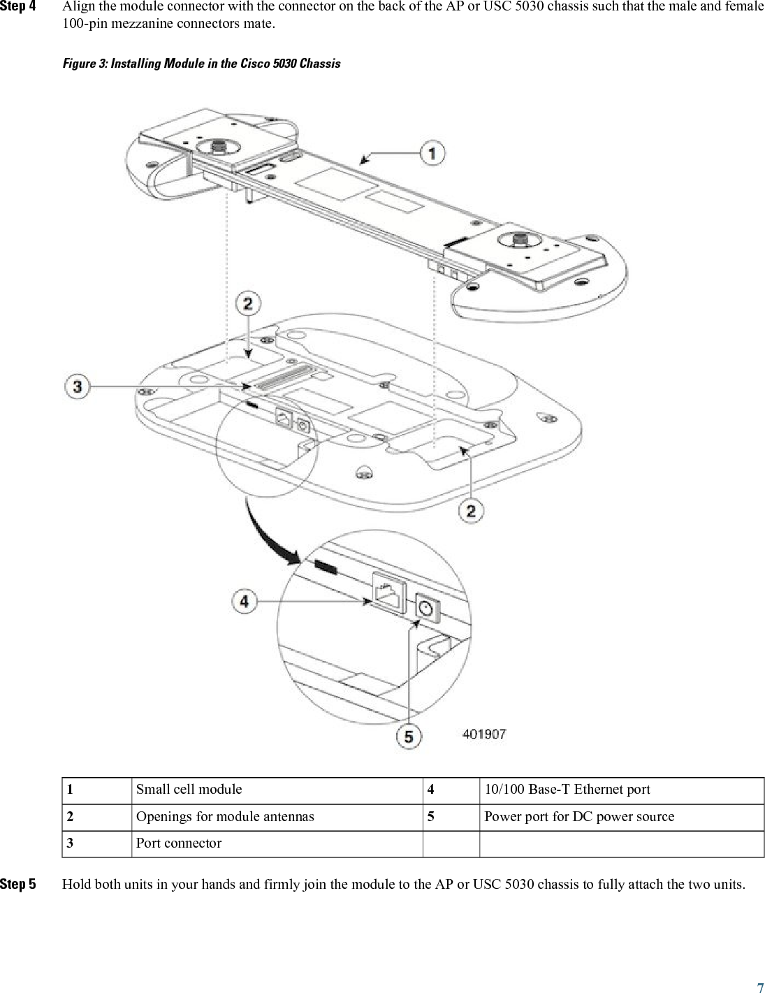

![This product is suitable for operation in a building's environmental air space, such as above suspendedceilings, in accordance with Section 300-22(C) of the National Electrical Code (NEC) and Sections 2-128,12-010(3) and 12-100 of the Canadian Electrical Code, Part 1, C22.1.Peut être utilisé dans des gaines transportant de l'air traité, conformément à la section 300-22(C) du NationalElectrical Code et aux articles 2l-128, 12-010(3) et 12-100 du Code Canadien de l'électricité, Premiérepartie, CSA C22.1.NoteThis Class [A/B] digital apparatus complies with Canadian ICES-003.Cet appareil numérique de la classe [A/B] est conforme à la norme NMB-003 du Canada.NoteStatement 8007—CE Mark for Class-II Radio EquipmentNoteUse only with listed ITE equipment.NoteIf you require assistance installing or operating your small cell, contact customer support.For warranty information, refer to: http://www.cisco-servicefinder.com/WarrantyFinder.aspx22](https://usermanual.wiki/SpiderCloud-Wireless/8818C24/User-Guide-2820729-Page-22.png)