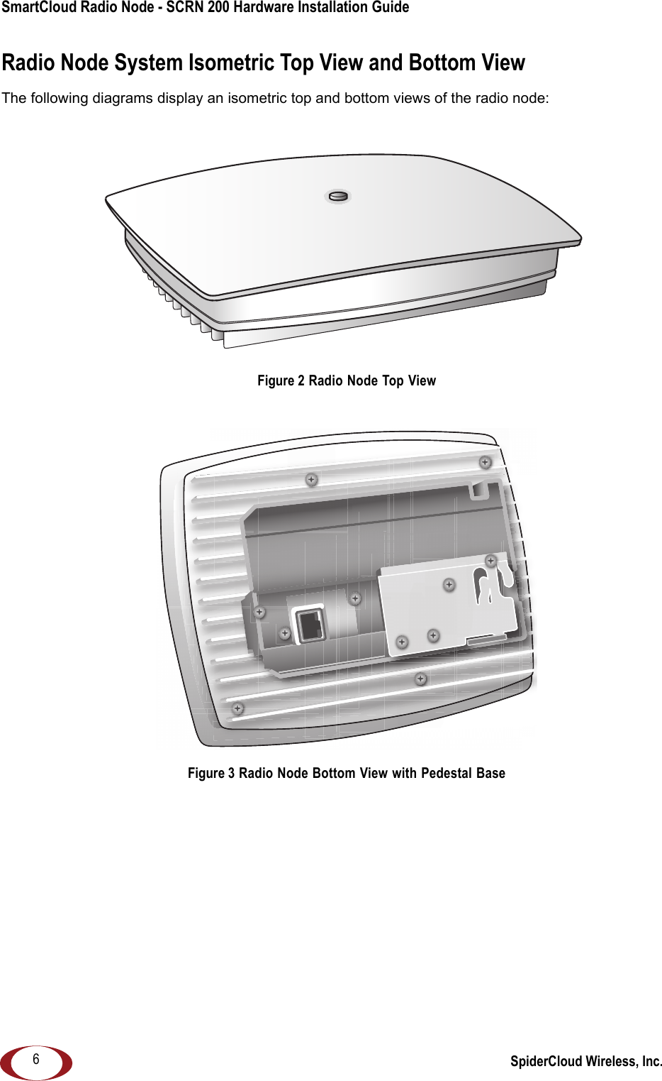
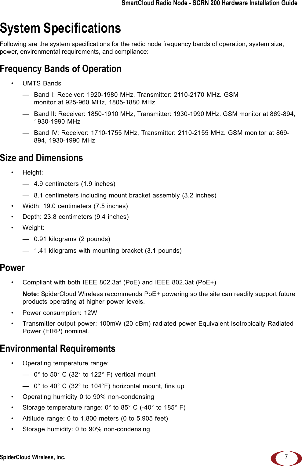
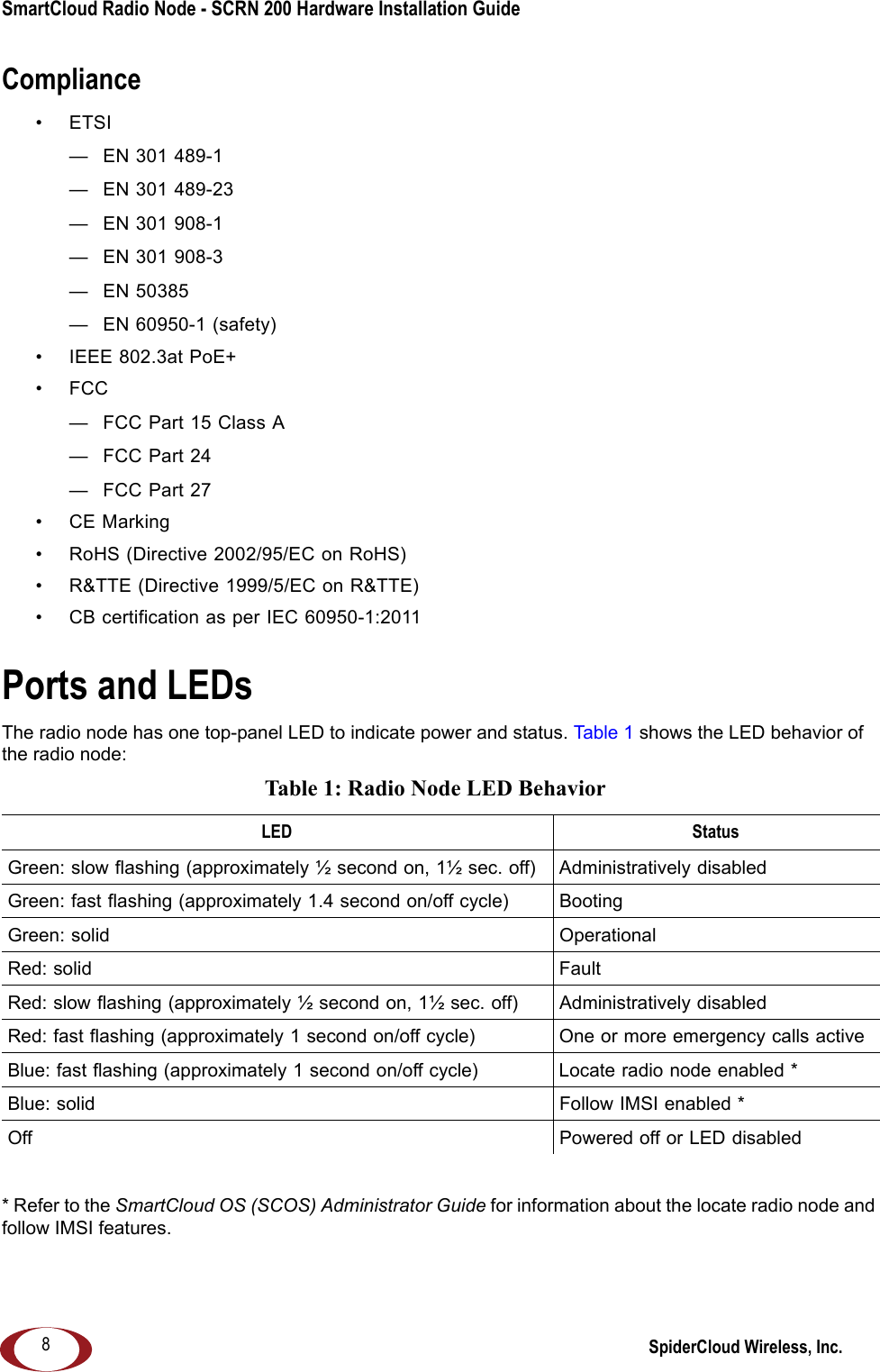
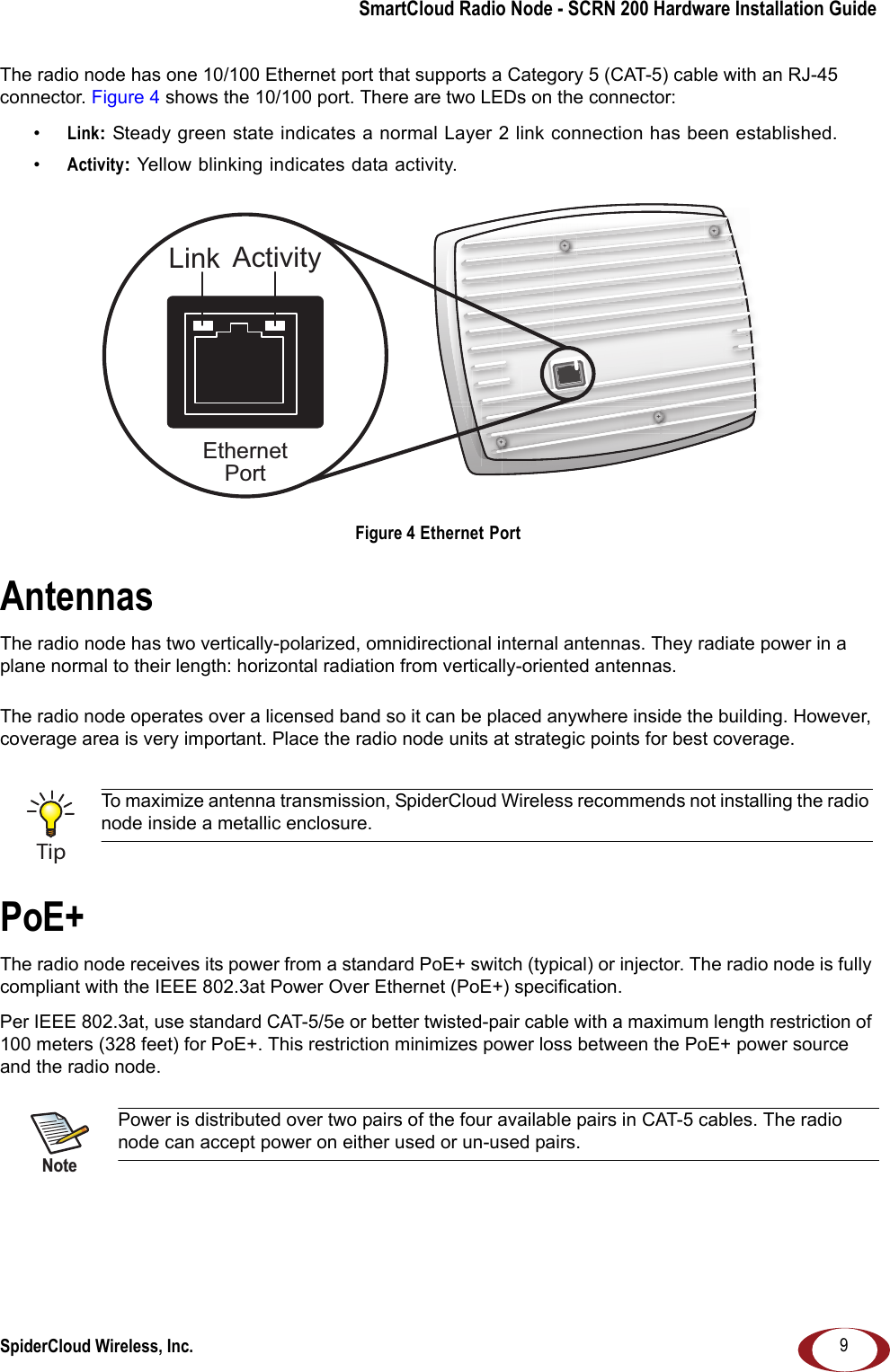
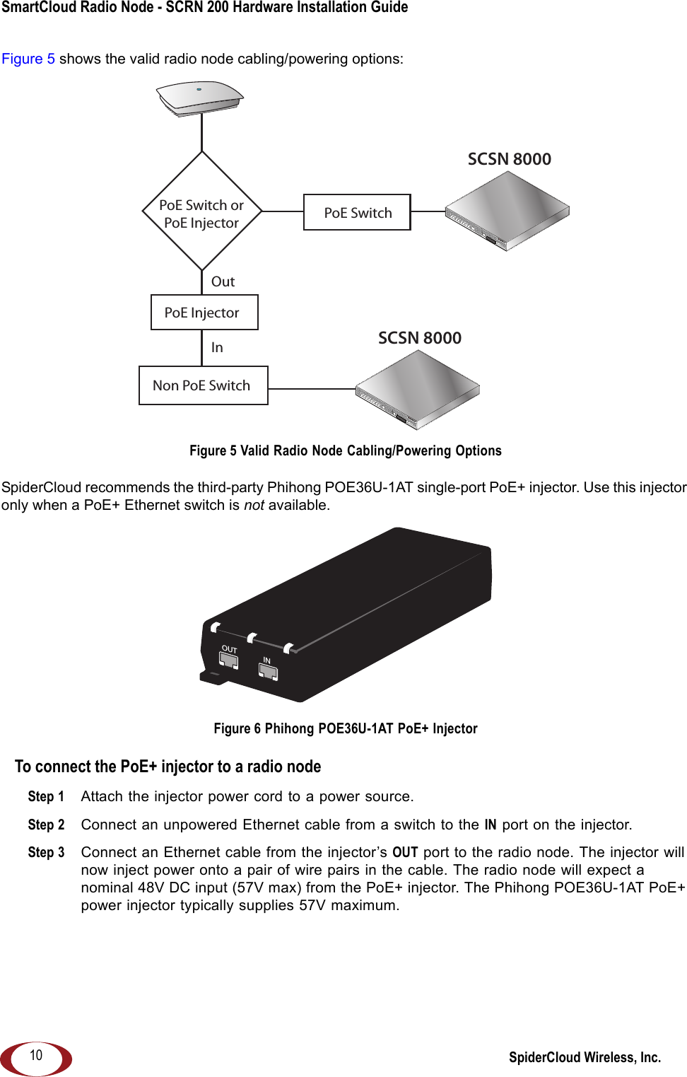
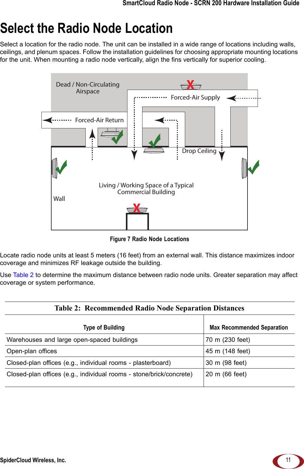
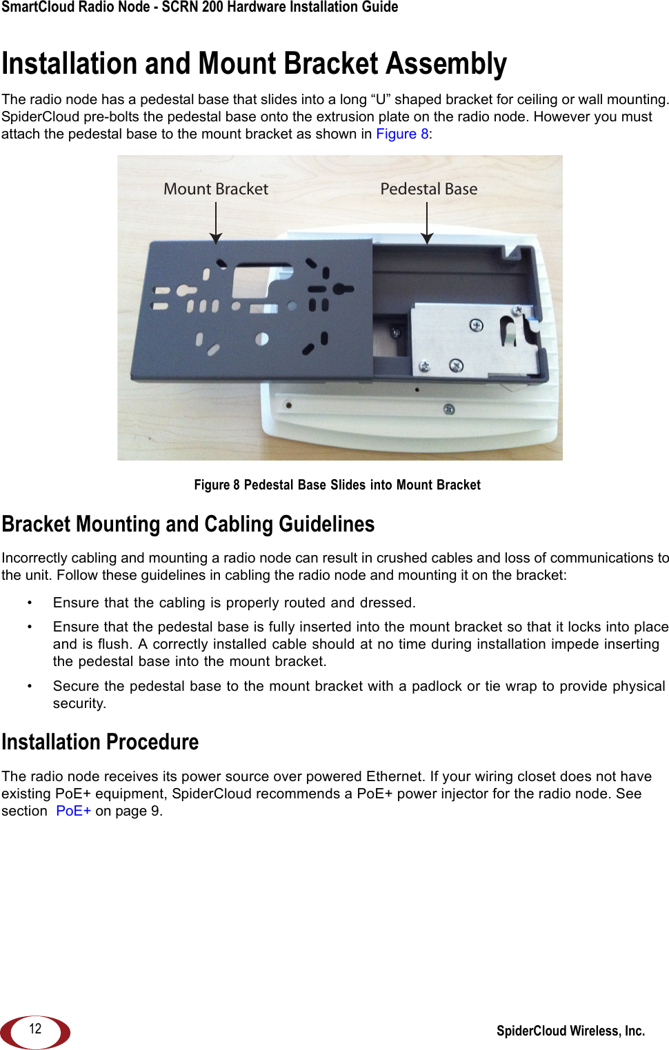
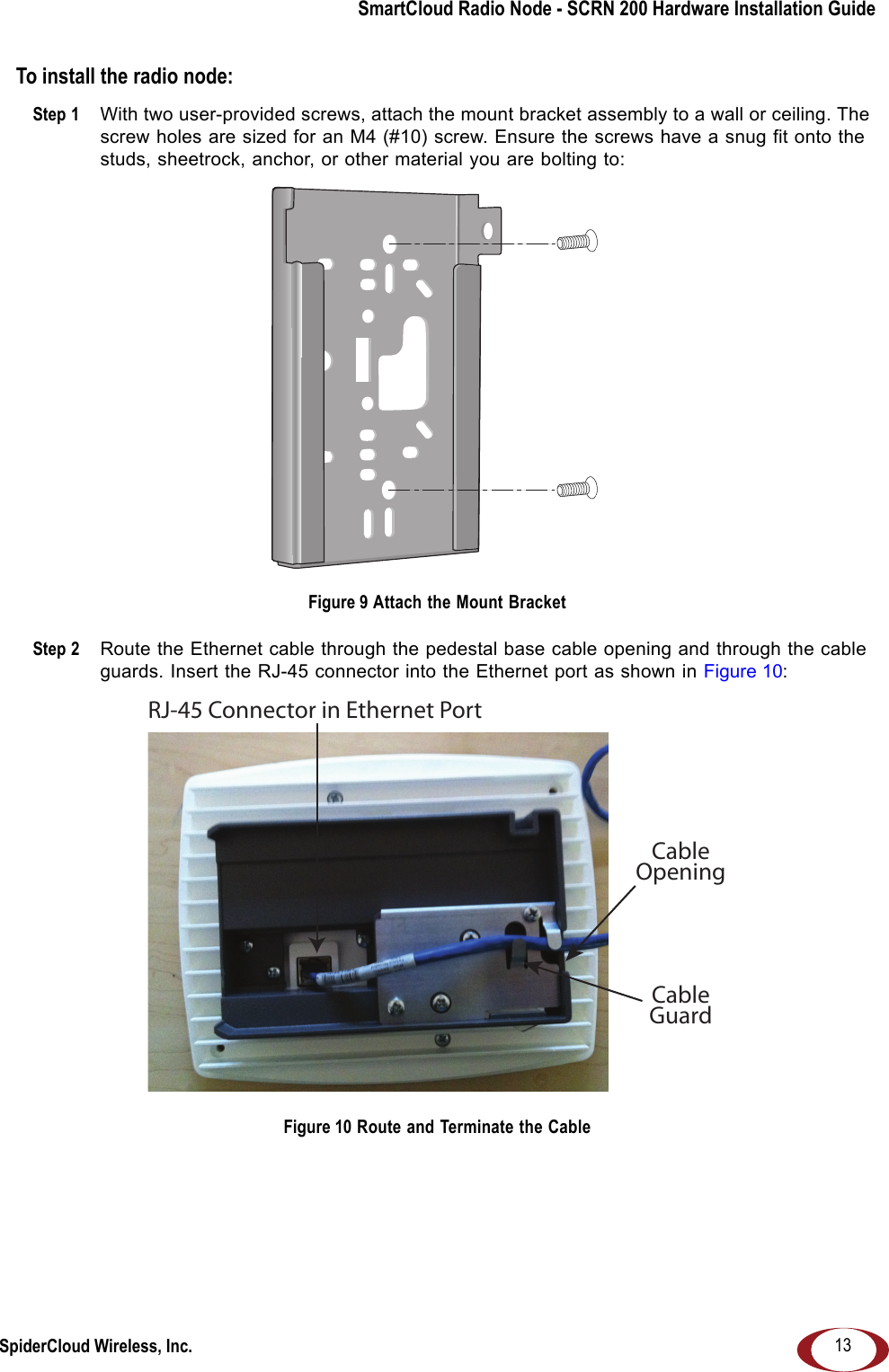
SpiderCloud Wireless RN200B2 High Capacity Indoor Radio Node for UMTS Coverage User Manual

SpiderCloud Wireless High Capacity Indoor Radio Node for UMTS Coverage Users Manual

Users Manual

SmartCloud® Radio Node - SCRN 200 Hardware Installation GuidePart number: DOC-RN-HW-05Published: December 2012
2© 2012 SpiderCloud Wireless, Inc. SpiderCloud and SmartCloud are registered trademarks of SpiderCloud Wireless, Inc. All Rights Reserved.FCC StatementsWarning: In order to avoid the possibility of exceeding the FCC radio frequency exposure limits, the SCRN 200 must have a minimum distance of 20 cm from the body during normal operation.Changes or modifications not expressly approved by SpiderCloud Wireless engineering voids the user’s authority to operate the equipment.Note: This equipment has been tested and found to comply with the limits for a Class A digital device, pursuant to part 15 of the FCC Rules. These limits are designed to provide reasonable protection against harmful interference when the equipment is operated in a commercial environment. This equipment generates, uses, and can radiate radio frequency energy and, if not installed and used in accordance with the instruction manual, may cause harmful interference to radio communications. Operation of this equipment in a residential area is likely to cause harmful interference, in which case, the user will be required to correct the interference at his own expense.SpiderCloud Wireless2500 Augustine DriveSuite 200Santa Clara, CA 95054, USAhttp://www.spidercloud.comTel: +1 408 567-9165Email: info@spidercloud.com
SpiderCloud Wireless, Inc.SmartCloud Radio Node - SCRN 200 Hardware Installation Guide3Table of ContentsSystem Overview . . . . . . . . . . . . . . . . . . . . . . . . . . . . . . . . . . . . . . . . . . . . . . . . . . . . . . . . . . . .  5Services Provided . . . . . . . . . . . . . . . . . . . . . . . . . . . . . . . . . . . . . . . . . . . . . . . . . . . . . . . . .  5Radio Node System Isometric Top View and Bottom View. . . . . . . . . . . . . . . . . . . . . . . . . .  6System Specifications. . . . . . . . . . . . . . . . . . . . . . . . . . . . . . . . . . . . . . . . . . . . . . . . . . . . . . . .  7Frequency Bands of Operation . . . . . . . . . . . . . . . . . . . . . . . . . . . . . . . . . . . . . . . . . . . . . . .  7Size and Dimensions. . . . . . . . . . . . . . . . . . . . . . . . . . . . . . . . . . . . . . . . . . . . . . . . . . . . . . . 7Power  . . . . . . . . . . . . . . . . . . . . . . . . . . . . . . . . . . . . . . . . . . . . . . . . . . . . . . . . . . . . . . . . . .  7Environmental Requirements  . . . . . . . . . . . . . . . . . . . . . . . . . . . . . . . . . . . . . . . . . . . . . . . .  7Compliance . . . . . . . . . . . . . . . . . . . . . . . . . . . . . . . . . . . . . . . . . . . . . . . . . . . . . . . . . . . . . .  8Ports and LEDs  . . . . . . . . . . . . . . . . . . . . . . . . . . . . . . . . . . . . . . . . . . . . . . . . . . . . . . . . . . . . .  8Antennas. . . . . . . . . . . . . . . . . . . . . . . . . . . . . . . . . . . . . . . . . . . . . . . . . . . . . . . . . . . . . . . . . . .  9PoE+ . . . . . . . . . . . . . . . . . . . . . . . . . . . . . . . . . . . . . . . . . . . . . . . . . . . . . . . . . . . . . . . . . . . . . .  9Select the Radio Node Location . . . . . . . . . . . . . . . . . . . . . . . . . . . . . . . . . . . . . . . . . . . . . . . .  11Installation and Mount Bracket Assembly. . . . . . . . . . . . . . . . . . . . . . . . . . . . . . . . . . . . . . . .  12Bracket Mounting and Cabling Guidelines  . . . . . . . . . . . . . . . . . . . . . . . . . . . . . . . . . . . . . .  12Installation Procedure . . . . . . . . . . . . . . . . . . . . . . . . . . . . . . . . . . . . . . . . . . . . . . . . . . . . . .  12Detaching the Radio Node from the Mount Bracket . . . . . . . . . . . . . . . . . . . . . . . . . . . . . . .  15Boot Sequence and Services Node Communication . . . . . . . . . . . . . . . . . . . . . . . . . . . . . . .  15Related Documents . . . . . . . . . . . . . . . . . . . . . . . . . . . . . . . . . . . . . . . . . . . . . . . . . . . . . . . . . .  16Index . . . . . . . . . . . . . . . . . . . . . . . . . . . . . . . . . . . . . . . . . . . . . . . . . . . . . . . . . . . . . . . . . . . . . .  17
SpiderCloud Wireless, Inc.Contents 4
SpiderCloud Wireless, Inc. 5SmartCloud Radio Node - SCRN 200 Hardware Installation GuideSystem OverviewThe SmartCloud® Radio Node 200 (SCRN 200) is a low-cost, low-power (100mW) base station designed for indoor use. The radio node is 3GPP compliant, supporting Universal Mobile Telecommunications System (UMTS) Release 6 software.The radio node provides enterprises with dedicated coverage and capacity for UMTS services. It is easy to install and connects to the existing enterprise LAN using standard Ethernet cabling. The radio node is managed by the SmartCloud Services Node 8000 (SCSN 8000) access controller. Figure 1 Radio Node Relationship to Enterprise and Carrier Core NetworksServices ProvidedThe radio node provides the following services:• Complete enterprise mobility using licensed spectrum• Radio Frequency (RF) self-calibration for autonomous setup, operation, and management• Enhanced networking• Transparent integration into enterprise network environmentsLAN IntranetDMZEnterpriseCarrier CoreDHCPEmail WebIur Interface(between Controllers/RNCs)3G CipherUu IntPoE+ InjectorSCRN 200sSGSNMSCIPSecBackhaulIPsecSwitch Switch FirewallSecurityGatewaySCSN 8000SCSN 8000Iu-CSIu-PSIPsec
SmartCloud Radio Node - SCRN 200 Hardware Installation Guide SpiderCloud Wireless, Inc.6Radio Node System Isometric Top View and Bottom ViewThe following diagrams display an isometric top and bottom views of the radio node:Figure 2 Radio Node Top ViewFigure 3 Radio Node Bottom View with Pedestal Base
SmartCloud Radio Node - SCRN 200 Hardware Installation GuideSpiderCloud Wireless, Inc. 7System SpecificationsFollowing are the system specifications for the radio node frequency bands of operation, system size, power, environmental requirements, and compliance:Frequency Bands of Operation• UMTS Bands— Band I: Receiver: 1920-1980 MHz, Transmitter: 2110-2170 MHz. GSM monitor at 925-960 MHz, 1805-1880 MHz— Band II: Receiver: 1850-1910 MHz, Transmitter: 1930-1990 MHz. GSM monitor at 869-894, 1930-1990 MHz— Band IV: Receiver: 1710-1755 MHz, Transmitter: 2110-2155 MHz. GSM monitor at 869-894, 1930-1990 MHzSize and Dimensions• Height: — 4.9 centimeters (1.9 inches)— 8.1 centimeters including mount bracket assembly (3.2 inches)• Width: 19.0 centimeters (7.5 inches)• Depth: 23.8 centimeters (9.4 inches)• Weight:— 0.91 kilograms (2 pounds)— 1.41 kilograms with mounting bracket (3.1 pounds)Power• Compliant with both IEEE 802.3af (PoE) and IEEE 802.3at (PoE+)Note: SpiderCloud Wireless recommends PoE+ powering so the site can readily support future products operating at higher power levels.• Power consumption: 12W• Transmitter output power: 100mW (20 dBm) radiated power Equivalent Isotropically Radiated Power (EIRP) nominal. Environmental Requirements• Operating temperature range: — 0° to 50° C (32° to 122° F) vertical mount— 0° to 40° C (32° to 104°F) horizontal mount, fins up• Operating humidity 0 to 90% non-condensing• Storage temperature range: 0° to 85° C (-40° to 185° F)• Altitude range: 0 to 1,800 meters (0 to 5,905 feet)• Storage humidity: 0 to 90% non-condensing
SmartCloud Radio Node - SCRN 200 Hardware Installation Guide SpiderCloud Wireless, Inc.8Compliance•ETSI— EN 301 489-1— EN 301 489-23— EN 301 908-1— EN 301 908-3— EN 50385— EN 60950-1 (safety)• IEEE 802.3at PoE+•FCC— FCC Part 15 Class A— FCC Part 24— FCC Part 27•CE Marking• RoHS (Directive 2002/95/EC on RoHS)• R&TTE (Directive 1999/5/EC on R&TTE)• CB certification as per IEC 60950-1:2011 Ports and LEDsThe radio node has one top-panel LED to indicate power and status. Tab le 1  shows the LED behavior of the radio node: * Refer to the SmartCloud OS (SCOS) Administrator Guide for information about the locate radio node and follow IMSI features.Table 1: Radio Node LED Behavior LED StatusGreen: slow flashing (approximately ½ second on, 1½ sec. off) Administratively disabledGreen: fast flashing (approximately 1.4 second on/off cycle) BootingGreen: solid OperationalRed: solid FaultRed: slow flashing (approximately ½ second on, 1½ sec. off) Administratively disabledRed: fast flashing (approximately 1 second on/off cycle) One or more emergency calls activeBlue: fast flashing (approximately 1 second on/off cycle) Locate radio node enabled *Blue: solid Follow IMSI enabled *Off Powered off or LED disabled
SmartCloud Radio Node - SCRN 200 Hardware Installation GuideSpiderCloud Wireless, Inc. 9The radio node has one 10/100 Ethernet port that supports a Category 5 (CAT-5) cable with an RJ-45 connector. Figure 4 shows the 10/100 port. There are two LEDs on the connector:•Link: Steady green state indicates a normal Layer 2 link connection has been established. •Activity: Yellow blinking indicates data activity. Figure 4 Ethernet PortAntennasThe radio node has two vertically-polarized, omnidirectional internal antennas. They radiate power in a plane normal to their length: horizontal radiation from vertically-oriented antennas.The radio node operates over a licensed band so it can be placed anywhere inside the building. However, coverage area is very important. Place the radio node units at strategic points for best coverage.PoE+The radio node receives its power from a standard PoE+ switch (typical) or injector. The radio node is fully compliant with the IEEE 802.3at Power Over Ethernet (PoE+) specification. Per IEEE 802.3at, use standard CAT-5/5e or better twisted-pair cable with a maximum length restriction of 100 meters (328 feet) for PoE+. This restriction minimizes power loss between the PoE+ power source and the radio node. To maximize antenna transmission, SpiderCloud Wireless recommends not installing the radio node inside a metallic enclosure.Power is distributed over two pairs of the four available pairs in CAT-5 cables. The radio node can accept power on either used or un-used pairs.EthernetPortLink ActivityTipNote
SmartCloud Radio Node - SCRN 200 Hardware Installation Guide SpiderCloud Wireless, Inc.10Figure 5 shows the valid radio node cabling/powering options:Figure 5 Valid Radio Node Cabling/Powering OptionsSpiderCloud recommends the third-party Phihong POE36U-1AT single-port PoE+ injector. Use this injector only when a PoE+ Ethernet switch is not available. Figure 6 Phihong POE36U-1AT PoE+ InjectorTo connect the PoE+ injector to a radio nodeStep 1  Attach the injector power cord to a power source.Step 2  Connect an unpowered Ethernet cable from a switch to the IN port on the injector. Step 3  Connect an Ethernet cable from the injector’s OUT port to the radio node. The injector will now inject power onto a pair of wire pairs in the cable. The radio node will expect a nominal 48V DC input (57V max) from the PoE+ injector. The Phihong POE36U-1AT PoE+ power injector typically supplies 57V maximum.SCSN 8000PoE SwitchOutIn SCSN 8000PoE Switch orPoE InjectorPoE InjectorNon PoE SwitchOUT INCONNECT PoEPLUS ON
SmartCloud Radio Node - SCRN 200 Hardware Installation GuideSpiderCloud Wireless, Inc. 11Select the Radio Node LocationSelect a location for the radio node. The unit can be installed in a wide range of locations including walls, ceilings, and plenum spaces. Follow the installation guidelines for choosing appropriate mounting locations for the unit. When mounting a radio node vertically, align the fins vertically for superior cooling.  Figure 7 Radio Node LocationsLocate radio node units at least 5 meters (16 feet) from an external wall. This distance maximizes indoor coverage and minimizes RF leakage outside the building. Use Table 2 to determine the maximum distance between radio node units. Greater separation may affect coverage or system performance.  Table 2:  Recommended Radio Node Separation DistancesType of Building Max Recommended SeparationWarehouses and large open-spaced buildings 70 m (230 feet)Open-plan offices 45 m (148 feet)Closed-plan offices (e.g., individual rooms - plasterboard) 30 m (98 feet)Closed-plan offices (e.g., individual rooms - stone/brick/concrete) 20 m (66 feet)Dead / Non-CirculatingAirspaceLiving / Working Space of a TypicalCommercial BuildingDrop CeilingWallForced-Air SupplyForced-Air ReturnXX
SmartCloud Radio Node - SCRN 200 Hardware Installation Guide SpiderCloud Wireless, Inc.12Installation and Mount Bracket AssemblyThe radio node has a pedestal base that slides into a long “U” shaped bracket for ceiling or wall mounting. SpiderCloud pre-bolts the pedestal base onto the extrusion plate on the radio node. However you must attach the pedestal base to the mount bracket as shown in Figure 8: Figure 8 Pedestal Base Slides into Mount BracketBracket Mounting and Cabling GuidelinesIncorrectly cabling and mounting a radio node can result in crushed cables and loss of communications to the unit. Follow these guidelines in cabling the radio node and mounting it on the bracket:• Ensure that the cabling is properly routed and dressed. • Ensure that the pedestal base is fully inserted into the mount bracket so that it locks into place and is flush. A correctly installed cable should at no time during installation impede inserting the pedestal base into the mount bracket. • Secure the pedestal base to the mount bracket with a padlock or tie wrap to provide physical security.Installation ProcedureThe radio node receives its power source over powered Ethernet. If your wiring closet does not have existing PoE+ equipment, SpiderCloud recommends a PoE+ power injector for the radio node. See section  PoE+ on page 9.Mount Bracket Pedestal Base
SmartCloud Radio Node - SCRN 200 Hardware Installation GuideSpiderCloud Wireless, Inc. 13To install the radio node:Step 1  With two user-provided screws, attach the mount bracket assembly to a wall or ceiling. The screw holes are sized for an M4 (#10) screw. Ensure the screws have a snug fit onto the studs, sheetrock, anchor, or other material you are bolting to: Figure 9 Attach the Mount BracketStep 2  Route the Ethernet cable through the pedestal base cable opening and through the cable guards. Insert the RJ-45 connector into the Ethernet port as shown in Figure 10: Figure 10 Route and Terminate the CableRJ-45 Connector in Ethernet PortCableOpeningCableGuard
SmartCloud Radio Node - SCRN 200 Hardware Installation Guide SpiderCloud Wireless, Inc.14Step 3  Slide the pedestal base of the radio node into the groove opening in the mount bracket. When the pedestal reaches the end of the trough, a spring clip will secure the unit into place: Figure 11 Slide the Mount Bracket onto the Pedestal Base Figure 12 Fully MountedStep 4  Attach a padlock or cable tie wrap through the cutout lock holes in the mount bracket and pedestal base: Figure 13 Lock Holes SpringClipLockHoles
SmartCloud Radio Node - SCRN 200 Hardware Installation GuideSpiderCloud Wireless, Inc. 15Step 5  The radio node boots up and attempts to connect to the services node. See Boot Sequence and Services Node Communication on page 15 for details.Detaching the Radio Node from the Mount BracketTo remove the radio node from the bracket assemblyStep 1  If needed, remove the padlock or cable tie wrap securing the radio node.Step 2  Depress the spring clip on the pedestal base and slide the radio node out of the mount bracket.Step 3  Detach the RJ-45 clip from the Ethernet port and remove the cable from cable brackets and cable opening.Boot Sequence and Services Node CommunicationOn initial boot, the radio node performs the following boot sequence and communicates with the services node. This sequence takes about one minute to complete. When completed, all devices are reachable:Figure 14 Radio Node Boot SequenceThe lock in the above figure is shown schematically. The orientation is for illustration purposes (not accurate) since the bracket is wall or ceiling mounted.NoteUSB CONSOLELK AT LK AT LK AT LK AT LK AT LK AT LK AT LK AT81234567LNK ACTMGMTPOWER STATUS 1 2SIM 0 SIM 1Radio Node Services Node DHCP ServerDHCP Request for IP AddressDHCP Response (RN, IP, Controller IP)Join RequestJoin Response (Join Grant, Redirect, Denied)Arrival sequence beginsSend SpiderCloud software packageMount package, join the network
SmartCloud Radio Node - SCRN 200 Hardware Installation Guide SpiderCloud Wireless, Inc.16Sequence description:1.  When the radio node is powered on, the device sends a DHCP Request to the network DHCP server to get IP information.2.  The DHCP server is configured to use vendor Option 43. The server responds with the IP addresses of the radio node and the services node (the master of the radio node). The following example shows a sample configuration from a DHCP server, where 10.1.30.99 is the IP address of the radio node’s controlling services node:option space SPIDERCLOUD;option SPIDERCLOUD.access-controller code 102 = string;option SPIDERCLOUD.access-controller "10.1.30.99;";3.  Using its own IP address, the radio node sends a Join Request message to the services node. The radio node seeks to join the cellular network. 4.  The Join Response from the services node will be one of the following:—Join Grant: Permit the radio node to join the services node.—Redirect: Redirect the radio node to join a different services node if you have multiple services node units configured in the network.—Denied: The security signature on the radio node does not match what the services node expects. The client is untrusted and treated as a rogue device. 5.  The arrival sequence begins. Based on the configuration of the radio node, the radio node will join the system and get its configuration. The services node sends the SpiderCloud software image (the system image and configuration settings) to the radio node. 6.  The radio node reboots and mounts the SpiderCloud software image as a RAM-based file system.7.  The radio node contacts the services node and joins the network.Related DocumentsRefer to the following documents for more information:•The SmartCloud System Description provides an overview of how the SmartCloud system fits within an operator’s network and in an enterprise, describes key features of the system, and provides specifications for the services and radio nodes.•The SmartCloud OS (SCOS) Administrator Guide to configure the software environment and internetworking between the services node and radio node devices.•The SmartCloud Services Node - SCSN 8000 Hardware Installation Guide for hardware specifications and installation instructions.•The SCOS NB Data Model Reference for details about objects and parameters that comprise the system configuration and operational state.
SmartCloud Radio Node - SCRN 200 Hardware Installation GuideIndex17Aactivity LED 9altitude range 7antennas 9Bboot sequence 15bottom view 6Ccabling guidelines 12CB certification 8CE marking 8compliance 8Ddepth 7detaching 15DHCP request 16EEIRP compliance 7environmental requirements 7FFCC compliance 8frequency bands of operation 7Hheight 7Iinstalling 12LLEDs 8link LED 9locating 11Mmount bracket 12Ooperating humidity range 7operating temperature range 7Ppedestal base 12PoE+ 9power 7RR&TTE compliance 8related documentation 16relative humidity range 7RoHS compliance 8Sseparation distances 11services 5specifications 7storage temperature range 7system diagram 5system specifications 7Ttop view 6UUMTS bands 7Wweight 7width 7Index
SpiderCloud Wireless, Inc.Index18

Navigation menu