SpiderCloud Wireless RN200HB2 High Capacity Indoor Radio Node for UMTS Coverage User Manual 1
SpiderCloud Wireless High Capacity Indoor Radio Node for UMTS Coverage 1
Contents
- 1. user manual 1
- 2. User Manual 2
user manual 1
SpiderCloud® Radio Node - SCRN-200
Hardware Installation Guide
Part number: DOC-SCRN-HW-07, Rev. 1
Published: December 2012
®

2
© 2012 SpiderCloud Wireless, Inc, SpiderCloud, and SpiderNet are registered trademarks of SpiderCloud
Wireless, Inc. All Rights Reserved.
FCC Statements
Caution: Any changes or modification cautions to this device not explicitly approved by manufacturer could
void your authority to operate this equipment.
This equipment complies with FCC radiation exposure limits set forth for an uncontrolled environment. This
equipment should be installed and operated with minimum 20 cm between the radiator and your body. This
transmitter must not be collocated or operating in conjunction with any other antenna or transmitter unless
authorized to do so by the FCC.
Industry Canada Statements
This Class [A/B] digital apparatus complies with Canadian ICES-003.
Cet appareil numérique de la classe [A/B] est conforme à la norme NMB-003 du Canada.
SpiderCloud Wireless
408 East Plumeria Drive
San Jose, CA 95134, USA
http://www.spidercloud.com
Tel: +1 408 567-9165
Email: info@spidercloud.com
Revision History
Revision Date Summary of Changes
1 12/04/2012 First release for SCOS R3.1

SpiderCloud Wireless, Inc.
SpiderCloud Radio Node - SCRN-200 Hardware Installation Guide
3
Table of Contents
About this Manual . . . . . . . . . . . . . . . . . . . . . . . . . . . . . . . . . . . . . . . . . . . . . . . . . . . . . . . . . . . 5
System Overview . . . . . . . . . . . . . . . . . . . . . . . . . . . . . . . . . . . . . . . . . . . . . . . . . . . . . . . . . . . . 5
Services Provided . . . . . . . . . . . . . . . . . . . . . . . . . . . . . . . . . . . . . . . . . . . . . . . . . . . . . . . . . 6
Radio Node System Isometric Top View and Bottom View. . . . . . . . . . . . . . . . . . . . . . . . . . 6
System Specifications. . . . . . . . . . . . . . . . . . . . . . . . . . . . . . . . . . . . . . . . . . . . . . . . . . . . . . . . 7
Frequency Bands of Operation . . . . . . . . . . . . . . . . . . . . . . . . . . . . . . . . . . . . . . . . . . . . . . . 7
Size and Dimensions. . . . . . . . . . . . . . . . . . . . . . . . . . . . . . . . . . . . . . . . . . . . . . . . . . . . . . . 7
Environmental Requirements . . . . . . . . . . . . . . . . . . . . . . . . . . . . . . . . . . . . . . . . . . . . . . . . 7
Power . . . . . . . . . . . . . . . . . . . . . . . . . . . . . . . . . . . . . . . . . . . . . . . . . . . . . . . . . . . . . . . . . . 7
Compliance . . . . . . . . . . . . . . . . . . . . . . . . . . . . . . . . . . . . . . . . . . . . . . . . . . . . . . . . . . . . . . 8
Radio Node Models . . . . . . . . . . . . . . . . . . . . . . . . . . . . . . . . . . . . . . . . . . . . . . . . . . . . . . . . . . 8
Antennas. . . . . . . . . . . . . . . . . . . . . . . . . . . . . . . . . . . . . . . . . . . . . . . . . . . . . . . . . . . . . . . . . . . 9
Ports . . . . . . . . . . . . . . . . . . . . . . . . . . . . . . . . . . . . . . . . . . . . . . . . . . . . . . . . . . . . . . . . . . . . . . 9
The Top-Panel LED . . . . . . . . . . . . . . . . . . . . . . . . . . . . . . . . . . . . . . . . . . . . . . . . . . . . . . . . . . 10
Input Power . . . . . . . . . . . . . . . . . . . . . . . . . . . . . . . . . . . . . . . . . . . . . . . . . . . . . . . . . . . . . . . . 10
Select the Radio Node Location . . . . . . . . . . . . . . . . . . . . . . . . . . . . . . . . . . . . . . . . . . . . . . . . 12
Installation and Mount Bracket Assembly. . . . . . . . . . . . . . . . . . . . . . . . . . . . . . . . . . . . . . . . 13
Bracket Mounting and Cabling Guidelines . . . . . . . . . . . . . . . . . . . . . . . . . . . . . . . . . . . . . . 14
Installing the Radio Node . . . . . . . . . . . . . . . . . . . . . . . . . . . . . . . . . . . . . . . . . . . . . . . . . . . 14
Installing the Radio Node (Method 1) . . . . . . . . . . . . . . . . . . . . . . . . . . . . . . . . . . . . . . . . . . 14
Installing the Radio Node (Method 2) . . . . . . . . . . . . . . . . . . . . . . . . . . . . . . . . . . . . . . . . . . 16
Completing the Installation . . . . . . . . . . . . . . . . . . . . . . . . . . . . . . . . . . . . . . . . . . . . . . . . . . 17
Detaching the Radio Node from the Mount Bracket . . . . . . . . . . . . . . . . . . . . . . . . . . . . . . . 18
Boot Sequence and Services Node Communication . . . . . . . . . . . . . . . . . . . . . . . . . . . . . . . 19
Radio Node LED Boot Sequence . . . . . . . . . . . . . . . . . . . . . . . . . . . . . . . . . . . . . . . . . . . . . . . 20
Radio Node LED Management . . . . . . . . . . . . . . . . . . . . . . . . . . . . . . . . . . . . . . . . . . . . . . . . . 21
The SpiderCloud Documentation Set . . . . . . . . . . . . . . . . . . . . . . . . . . . . . . . . . . . . . . . . . . . 22
Appendix, Antenna Patterns. . . . . . . . . . . . . . . . . . . . . . . . . . . . . . . . . . . . . . . . . . . . . . . . . . . 23
Index . . . . . . . . . . . . . . . . . . . . . . . . . . . . . . . . . . . . . . . . . . . . . . . . . . . . . . . . . . . . . . . . . . . . . . 27

SpiderCloud Wireless, Inc.
Contents
4
SpiderCloud Wireless, Inc. 5
SpiderCloud Radio Node - SCRN-200 Hardware Installation Guide
About this Manual
This guide provides the system specifications of the SpiderCloud® Radio Node 200 (SCRN-200). It
includes detailed hardware installation instructions, the boot sequence, and expected LED behavior both
during the boot-up and under operating conditions. An appendix shows the radio node antenna patterns.
The primary audience for this guide includes network planners, system administrators and installation
personnel. It assumes you have knowledge about networking principles, networking configuration, site
preparation, powering, and experience in hardware installation and maintenance.
System Overview
The SCRN-200 is a low-cost, low-power (100mW) base station designed for indoor use. The radio node is
3GPP compliant, supporting Universal Mobile Telecommunications System (UMTS) Release 6.
The radio node enables mobile operators to offer dedicated, in-building coverage and capacity for UMTS
services. It is easy to install and connects to the existing enterprise LAN using standard Ethernet cabling or
to a dedicated LAN infrastructure deployed for use by the operator. Radio nodes are managed by the
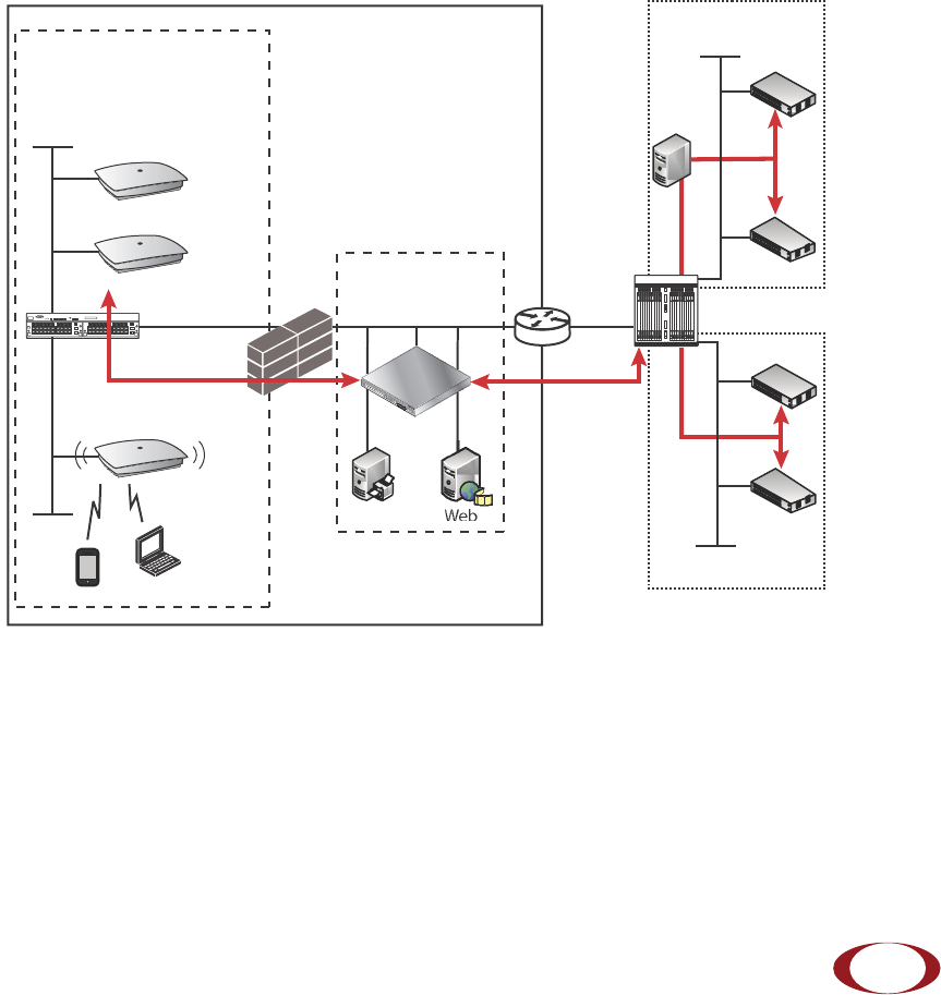
SpiderCloud Services Node 8000 (SCSN-8000) access controller, typically installed in the enterprise DMZ.
Figure 1 Radio Node Relationship to Enterprise and Mobile Operator Core Networks
LAN Intranet
DMZ
Enterprise Mobile
Operator Core
Email Web
Radio Nodes
SGSN
MSC
IPSec
Backhaul
IPsec
Switch Firewall Security
Gateway
SCSN-8000
Iu-CS
Iu-PS
IPsec
HNB
Gateway
Iuh
SGSN
MSC
Option 1
Option 2
Iu-CS
Iu-PS
3G
SpiderCloud Radio Node - SCRN-200 Hardware Installation Guide
SpiderCloud Wireless, Inc.
6
Services Provided
The radio node provides the following services:
• Complete enterprise mobility using licensed spectrum
• Radio Frequency (RF) self-calibration for autonomous setup, operation, and management
• Enhanced networking
• Transparent integration into enterprise network environments
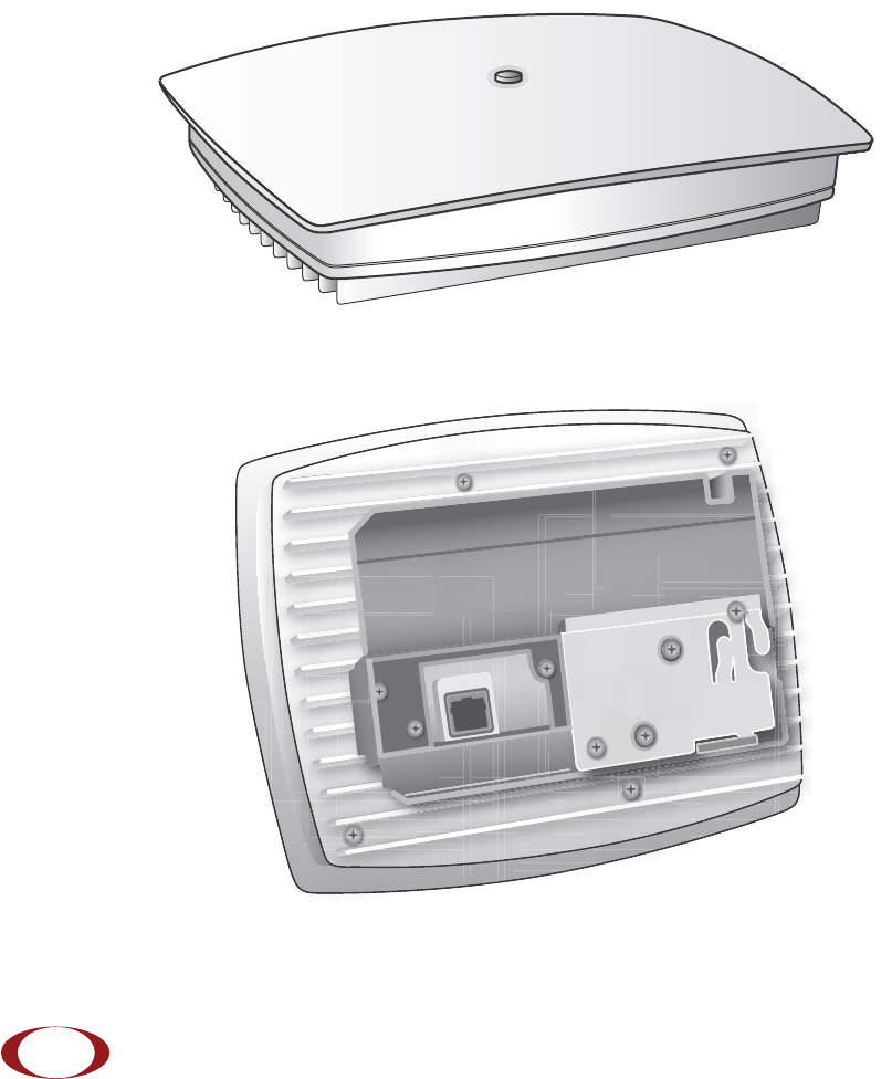
Radio Node System Isometric Top View and Bottom View
The radio node ships with either two internal antennas, or with two TNC connectors for use with external
antennas. The following drawings display an isometric top and bottom views of the radio node with internal
antennas:
Figure 2 Radio Node Top View
Figure 3 Radio Node Bottom View with Pedestal Base

SpiderCloud Radio Node - SCRN-200 Hardware Installation Guide
SpiderCloud Wireless, Inc. 7
System Specifications
Following are the system specifications for the radio node frequency bands of operation, system size,
environmental requirements, power, and compliance:
Frequency Bands of Operation
SpiderCloud Wireless provides three versions of the SCRN-200 for operation in the following bands:
• UMTS Band I: Receiver: 1920-1980 MHz, Transmitter: 2110-2170 MHz.
GSM monitor at 925-960 MHz, 1805-1880 MHz
• UMTS Band II: Receiver: 1850-1910 MHz, Transmitter: 1930-1990 MHz.
GSM monitor at 869-894, 1930-1990 MHz
• UMTS Band IV: Receiver: 1710-1755 MHz, Transmitter: 2110-2155 MHz.
GSM monitor at 869-894, 1930-1990 MHz
Size and Dimensions
• Height:
— 4.9 centimeters (1.9 inches)
— 8.1 centimeters including mount bracket assembly (3.2 inches)
• Width: 19.0 centimeters (7.5 inches)
• Length: 23.8 centimeters (9.4 inches)
• Weight (both models):
— 0.91 kilograms (2 pounds)
— 1.41 kilograms with mounting bracket (3.1 pounds)
Environmental Requirements
• Operating temperature range:
— 0° to 50° C (32° to 122° F) vertical mount
— 0° to 40° C (32° to 104°F) horizontal mount, fins up
• Operating humidity: 0 to 90% non-condensing
• Storage temperature range: 0° to 85° C (-40° to 185° F)
• Altitude range: 0 to 1,800 meters (0 to 5,905 feet)
• Storage humidity: 0 to 90% non-condensing
Power
The radio node is compliant with both IEEE 802.3af (PoE) and IEEE 802.3at (PoE+).
• Power consumption: 12W
SpiderCloud Wireless recommends PoE+ powering so the site can readily support future
products operating at higher power levels.
Note

SpiderCloud Radio Node - SCRN-200 Hardware Installation Guide
SpiderCloud Wireless, Inc.
8
• Two orderable options for transmitter output power:
— 100mW (20 dBm) RMS radio power
— 250mW (24 dBm) RMS radio power
Compliance
•ETSI:
— EN 301 489-1
— EN 301 489-23
— EN 301 908-1
— EN 301 908-3
— EN 50385
— EN 60950-1 (safety)
• IEEE 802.3at PoE+
• FCC:
— FCC Part 15 Class A
— FCC Part 24 (UMTS Band II only)
— FCC Part 27 (UMTS Band IV only)
•CE Marking
• NRTL Marking
• RoHS (Directive 2002/95/EC on RoHS)
• R&TTE (Directive 1999/5/EC on R&TTE)
• CB certification as per IEC 60950-1:2011
• Industry Canada: RSS-133, RSS-139, ICES-003 (Class A)
Radio Node Models
Tabl e 1 displays the orderable configurations of the SCRN-200 radio node:
Table 1: SCRN-200 Radio Node Configurations
Radio Node Model Description
SCRN-200-1 UMTS Band I, Internal antennas
SCRN-200-1E UMTS Band I, external antennas
SCRN 200-2 UMTS Band II, Internal antennas
SCRN-200-2E UMTS Band II, external antennas
SCRN 200-4 UMTS Band IV, external antennas
SCRN-200-4E UMTS Band IV, external antennas
SCRN-200-241 UMTS Band I, Internal antennas, 24dBm
SpiderCloud Radio Node - SCRN-200 Hardware Installation Guide
SpiderCloud Wireless, Inc. 9
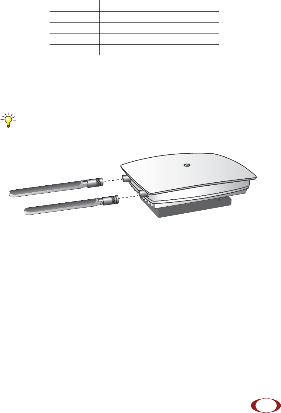
Antennas
The radio node uses two vertically-polarized, omnidirectional 2 dBi nominal gain antennas. Both antennas
receive, only one antenna transmits. One model has internal antennas. The other has two antenna ports
with TNC connectors for use with external antennas.
Figure 4 Typical External Antennas
For regulatory compliance, use only antennas certified by SpiderCloud Wireless.
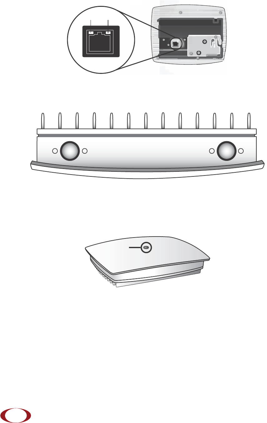
Ports
The radio node has one 10/100 Ethernet port that supports a Category 5e (Cat 5e) or better twisted-pair
cable with an RJ-45 connector. Figure 5 on page 10 shows the 10/100 port. There are two LEDs on the
connector:
•Link: Steady green state indicates a normal Layer 2 link connection has been established.
•Activity: Yellow blinking indicates data activity.
SCRN-200-242 UMTS Band II, Internal antennas, 24dBm
SCRN-200-242E UMTS Band II, external antennas, 24dBm
SCRN-200-244 UMTS Band IV, Internal antennas, 24dBm
SCRN-200-244E UMTS Band IV, external antennas, 24dBm
To maximize antenna transmission, SpiderCloud Wireless recommends not installing the radio
node inside a metallic enclosure.
Table 1: SCRN-200 Radio Node Configurations (continued)
Radio Node Model Description
Tip
SpiderCloud Radio Node - SCRN-200 Hardware Installation Guide
SpiderCloud Wireless, Inc.
10
Figure 5 Ethernet Port
The radio node for use with external antennas has two antenna ports with TNC connectors labeled A
and B. Connector A transmits and receives. Connector B is receive only.
Figure 6 Antenna Port TNC Connectors
The Top-Panel LED
The radio node has one top-panel tricolor LED to indicate power and status. This is the only LED visible
under normal operating conditions.
Figure 7 Radio Node Tricolor LED
When the radio node initially boots the LED cycles through a number of colors and flashing behaviors until
it is fully operational. Refer to Radio Node LED Boot Sequence on page 20 for more information about the
LED boot cycle and Radio Node LED Management on page 21 for information about LED management.
Input Power
The radio node receives its power from a standard PoE+ switch (typical) or injector. The radio node is fully
compliant with the IEEE 802.3at Power Over Ethernet (PoE+) specification. SpiderCloud Wireless
recommends PoE+ powering to support future products and functionalities operating at higher power
levels.
Ethernet
Port
Link Activity
AB
LED
SpiderCloud Radio Node - SCRN-200 Hardware Installation Guide
SpiderCloud Wireless, Inc. 11
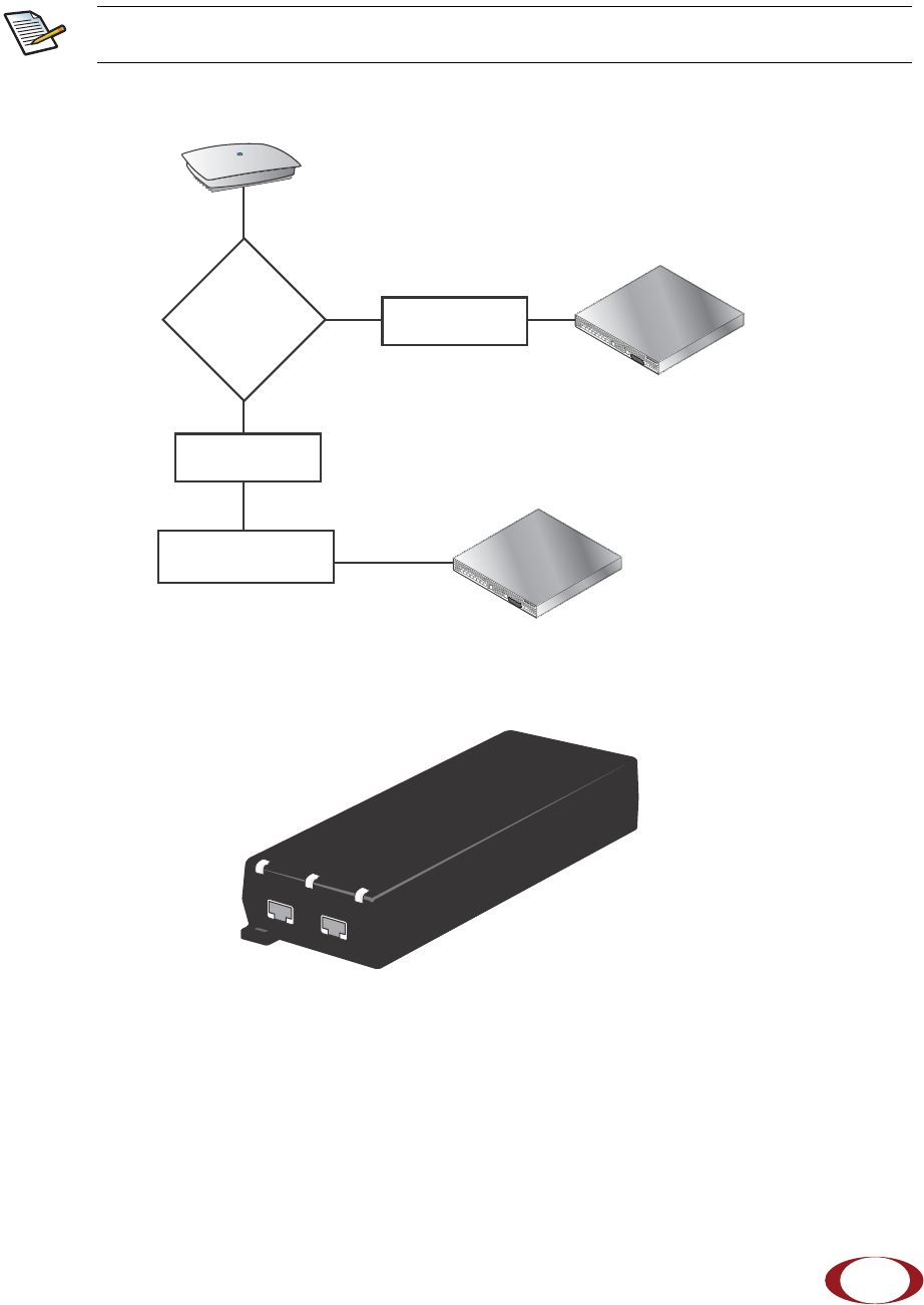
Per IEEE 802.3at, use standard Cat 5e or better twisted-pair cable with a maximum length restriction of
100 meters (328 feet) for PoE+. This restriction minimizes power loss between the PoE+ power source
and the radio node.
Figure 8 shows the valid radio node cabling/powering options:
Figure 8 Valid Radio Node Cabling/Powering Options
The illustration below shows a generic single-port PoE+ injector. Use this injector only when a PoE+
Ethernet switch is not available.
Figure 9 Typical PoE+ Injector
To connect the PoE+ injector to a radio node
Step 1 Attach the injector power cord to a power source.
Step 2 Connect an unpowered Ethernet cable from a switch to the IN port on the injector.
Power is distributed over two pairs of the four available pairs in Cat 5e cables. The radio
node can accept power on either used or un-used pairs.
Note
SCSN-8000
PoE Switch
Out
In SCSN-8000
PoE Switch or
PoE Injector
PoE Injector
Non PoE Switch
OUT IN
CONNECT PoEPLUS ON
SpiderCloud Radio Node - SCRN-200 Hardware Installation Guide
SpiderCloud Wireless, Inc.
12
Step 3 Connect an Ethernet cable from the injector’s OUT port to the radio node. The injector will
now inject power onto a pair of wire pairs in the cable. The radio node will expect a
nominal 48V DC input (57V max) from a typical PoE+ injector.
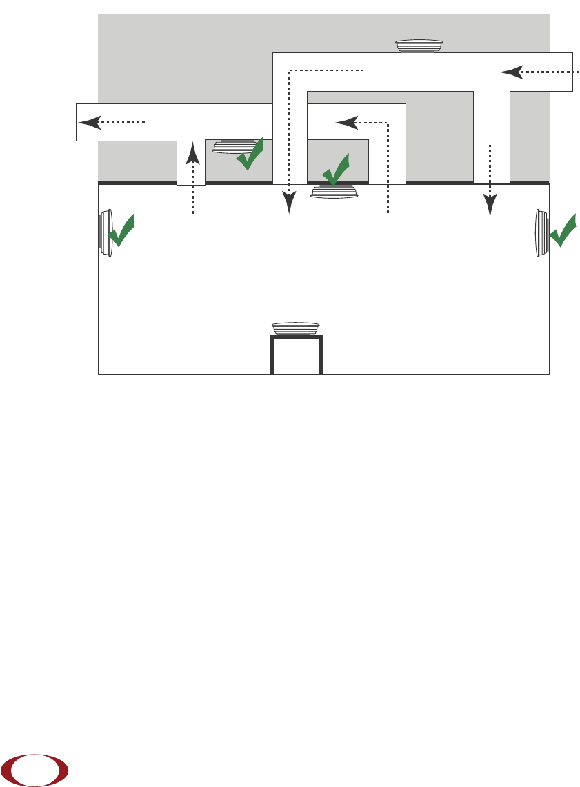
Select the Radio Node Location
Radio nodes can be installed in a wide range of locations including walls, ceilings, and plenum spaces.
Follow the installation guidelines for selecting appropriate mounting locations for the unit. When mounting
a radio node vertically, align the bottom-side fins vertically for superior cooling.
Figure 10 Radio Node Locations
When possible, locate radio node units at least 5 meters (16 feet) from an external wall. This distance
maximizes indoor coverage and minimizes RF leakage outside the building. When mounting near a wall or
other obstruction, orient the mounting bracket such that the transmit antenna faces towards the coverage
area and faces away from the wall. Refer to Bracket Mounting and Cabling Guidelines on page 14 for
more information.
Dead / Non-Circulating
Airspace
Living / Working Space of a Typical
Commercial Building
Drop Ceiling
Wall
Forced-Air Supply
Forced-Air Return
X
X
SpiderCloud Radio Node - SCRN-200 Hardware Installation Guide
SpiderCloud Wireless, Inc. 13
Use Table 2 to determine the maximum distance between radio node units. Greater separation may affect
coverage or system performance.
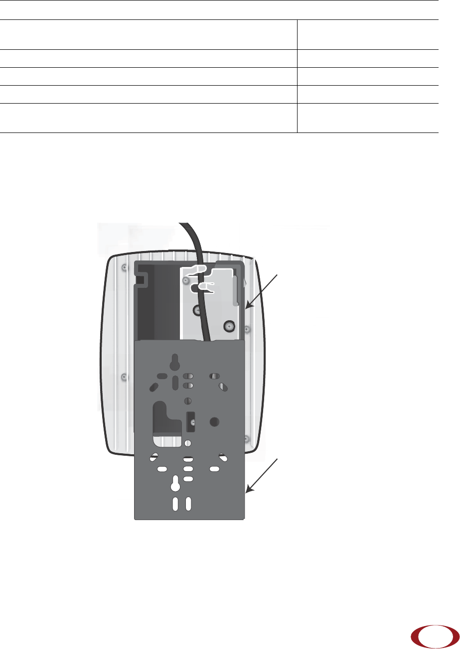
Installation and Mount Bracket Assembly
The radio node has a pedestal base that slides into a long bracket for ceiling or wall mounting. SpiderCloud
Wireless pre-bolts the pedestal base onto the extrusion plate on the radio node. However you must attach
the pedestal base to the mount bracket as shown in Figure 11:
Figure 11 Pedestal Base Slides into Mount Bracket
Table 2: Recommended Radio Node Separation Distances
Type of Building Max Recommended Separation
Warehouses and large open-spaced buildings 70 m (230 feet)
Open-plan offices 45 m (148 feet)
Closed-plan offices (e.g., individual rooms - plasterboard) 30 m (98 feet)
Closed-plan offices (e.g., individual rooms - stone/brick/concrete) 20 m (66 feet)
Mount Bracket
Pedestal Base
SpiderCloud Radio Node - SCRN-200 Hardware Installation Guide
SpiderCloud Wireless, Inc.
14
Bracket Mounting and Cabling Guidelines
Incorrectly cabling and mounting a radio node can result in crushed cables and loss of communications to
the unit. Follow these guidelines in cabling the radio node and mounting it on the bracket:
• Ensure that the cabling is properly routed and dressed.
• Ensure that the pedestal base is fully inserted into the mount bracket so that it locks into place
and is flush. A correctly installed cable should at no time during installation impede inserting
the pedestal base into the mount bracket.
• Secure the pedestal base to the mount bracket with a padlock or tie wrap to provide physical
security.
• When mounting the radio node vertically, orient the bracket with the open end on top and the
closed end on the bottom. Figure 12 on page 14 shows the proper vertical orientation.
• When mounting the radio node near a wall or other obstruction, orient the bracket such that the
radio node transmit side towards the coverage area. In vertical mountings, this is on the right
side of the radio node. Figure 12 on page 14 shows the mounting bracket orientation:
Installing the Radio Node
The radio node receives its power source over powered Ethernet. If your wiring closet does not have
existing PoE+ equipment, SpiderCloud Wireless recommends a PoE+ power injector for the radio node.
See section Input Power on page 10.
The Ethernet cable can route openly or directly through a surface such as a wall or ceiling:
• Refer to Installing the Radio Node (Method 1) on page 14 for open cable routing installation.
• Refer to Installing the Radio Node (Method 2) on page 16 for direct cable routing installation.
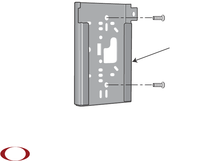
Installing the Radio Node (Method 1)
To route the cable openly and mount the radio node
Step 1 With two user-provided screws, attach the mount bracket assembly to a wall or ceiling. The
screw holes are sized for an M4 (#10) screw. Ensure the screws have a snug fit onto the
studs, sheetrock, anchor, or other material you are bolting onto.
Figure 12 Attach the Mount Bracket
Transmit Side