SpiderCloud Wireless RN800B4 A UMTS Femto Cell indoor base station to provide 3G voice and data service User Manual book
SpiderCloud Wireless A UMTS Femto Cell indoor base station to provide 3G voice and data service book
User Manual

Hardware Installation Guide for
SmartCloud® Radio Node - SCRN 800
Part number: DOC-RN-HW-02
Published: January 2011
© 2011 SpiderCloud Wireless, Inc. SpiderCloud and SmartCloud are registered trademarks of
SpiderCloud Wireless, Inc. All Rights Reserved.
FCC Statements
Warning: In order to avoid the possibility of exceeding the FCC radio frequency exposure
limits, the SCRN 800 must have a minimum distance of 20 cm from the body during normal
operation.
Changes or modifications not expressly approved by SpiderCloud Wireless engineering voids
the user’s authority to operate the equipment.
Note: This equipment has been tested and found to comply with the limits for a Class A digital
device, pursuant to part 15 of the FCC Rules. These limits are designed to provide reasonable
protection against harmful interference when the equipment is operated in a commercial
environment. This equipment generates, uses, and can radiate radio frequency energy and, if
not installed and used in accordance with the instruction manual, may cause harmful
interference to radio communications. Operation of this equipment in a residential area is
likely to cause harmful interference, in which case, the user will be required to correct the
interference at his own expense.
Industry Canada Statements
This device has been designed to operate with the antenna listed below and having a
maximum gain of 3 dB. Antennas not included in this list or having a gain greater than 3 dB
are strictly prohibited for use with this device. The required antenna impedance is 50 ohms.
• Laird MAF94307
• Larsen SPDA17806/2170
To reduce potential radio interference to other users, the antenna type and its gain should be
so chosen that the equivalent isotropically radiated power (e.i.r.p.) is not more than permitted
for successful communication.
SpiderCloud Wireless
2500 Augustine Drive
Suite 200
Santa Clara, CA 95054, USA
http://www.spidercloud.com
Tel: +1 408 567-9165
Email: info@spidercloud.com

SpiderCloud Wireless, Inc. iii
Contents
System Overview . . . . . . . . . . . . . . . . . . . . . . . . . . . . . . . . . . . . . . . . . 1
Services Provided . . . . . . . . . . . . . . . . . . . . . . . . . . . . . . . . . . . . . . 2
SCRN System Isometric Front View and Rear View . . . . . . . . . . . 2
System Specifications. . . . . . . . . . . . . . . . . . . . . . . . . . . . . . . . . . . . . . 3
Frequency Bands of Operation . . . . . . . . . . . . . . . . . . . . . . . . . . . . 3
Size and Dimensions. . . . . . . . . . . . . . . . . . . . . . . . . . . . . . . . . . . . 4
Power . . . . . . . . . . . . . . . . . . . . . . . . . . . . . . . . . . . . . . . . . . . . . . . 4
Environmental Requirements . . . . . . . . . . . . . . . . . . . . . . . . . . . . . 4
Compliance . . . . . . . . . . . . . . . . . . . . . . . . . . . . . . . . . . . . . . . . . . . 4
Ports and LEDs. . . . . . . . . . . . . . . . . . . . . . . . . . . . . . . . . . . . . . . . . . . 5
Antennas. . . . . . . . . . . . . . . . . . . . . . . . . . . . . . . . . . . . . . . . . . . . . . . . 7
Installation and Mount Bracket Assembly. . . . . . . . . . . . . . . . . . . . . . . 8
Installation Procedure . . . . . . . . . . . . . . . . . . . . . . . . . . . . . . . . . . . 9
Detaching the SCRN from the Mount Bracket. . . . . . . . . . . . . . . . . 14
PoE+. . . . . . . . . . . . . . . . . . . . . . . . . . . . . . . . . . . . . . . . . . . . . . . . . . . 15
Boot Sequence and SCSN Communication . . . . . . . . . . . . . . . . . . . . . 16
Related Documents . . . . . . . . . . . . . . . . . . . . . . . . . . . . . . . . . . . . . . . 17
Index . . . . . . . . . . . . . . . . . . . . . . . . . . . . . . . . . . . . . . . . . . . . . . . . . . . 19

SpiderCloud Wireless, Inc.
Contents
iv
SpiderCloud Wireless, Inc. 1
System Overview
The SmartCloud® Radio Node 800 (SCRN 800) is a low-cost, low-power (100mW) Node B
designed for enterprises.
The SCRN is 3GPP compliant, supporting Universal Mobile Telecommunications System
(UMTS) Release 6 software and is upgradable to Release 7 and 8.
The SCRN provides enterprises with dedicated high-quality, high-capacity UMTS coverage.
The SCRN is easy to install and connects to the existing enterprise LAN using standard
Ethernet cabling.
The SCRN is managed by the SmartCloud® Services Node 8000 (SCSN 8000).
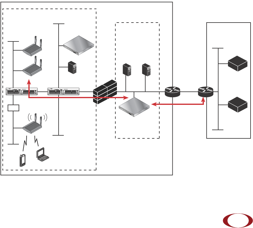
Figure 1 SCRN Relationship to Enterprise and Carrier Core Networks
LAN Intranet
DMZ
Enterprise
Carrier Core
DHCP
Email Web
Iu-CS, Iu-PS,
Iuh Interfaces
Iur Interface
(between Controllers/RNCs)
3G Cipher
Uu Int
PoE+ Injector
SCRN 800
Iu/Iuh
Aggregator
ACS
IPSec
Backhaul
1588
Iub Int
RADIO
STATUS
RADIO
STATUS
RADIO
STATUS
Switch Switch
Firewall
Security
Gateway
SCSN 8000
SCSN 8000
SpiderCloud Wireless, Inc.
System Overview
2
Services Provided
The SCRN provides the following services:
• Complete enterprise mobility using licensed spectrum.
• RF self-calibration for autonomous setup, operation, and management.
• Enhanced networking.
• Transparent integration into enterprise network environments.
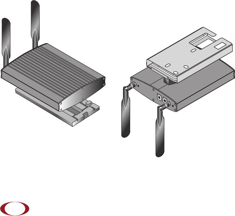
SCRN System Isometric Front View and Rear View
The following diagrams display an isometric front view and rear view of the SCRN.
Figure 2 Isometric Views with Mount-Bracket Assembly
ANT BANT A
ETHERNET CONSO LE
ANT B
RADIO
STATUS
SpiderCloud
Wireless
SCRN800
SpiderCloud Wireless, Inc.
Hardware Installation Guide for SmartCloud® Radio Node - SCRN 800
3
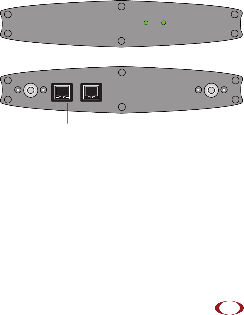
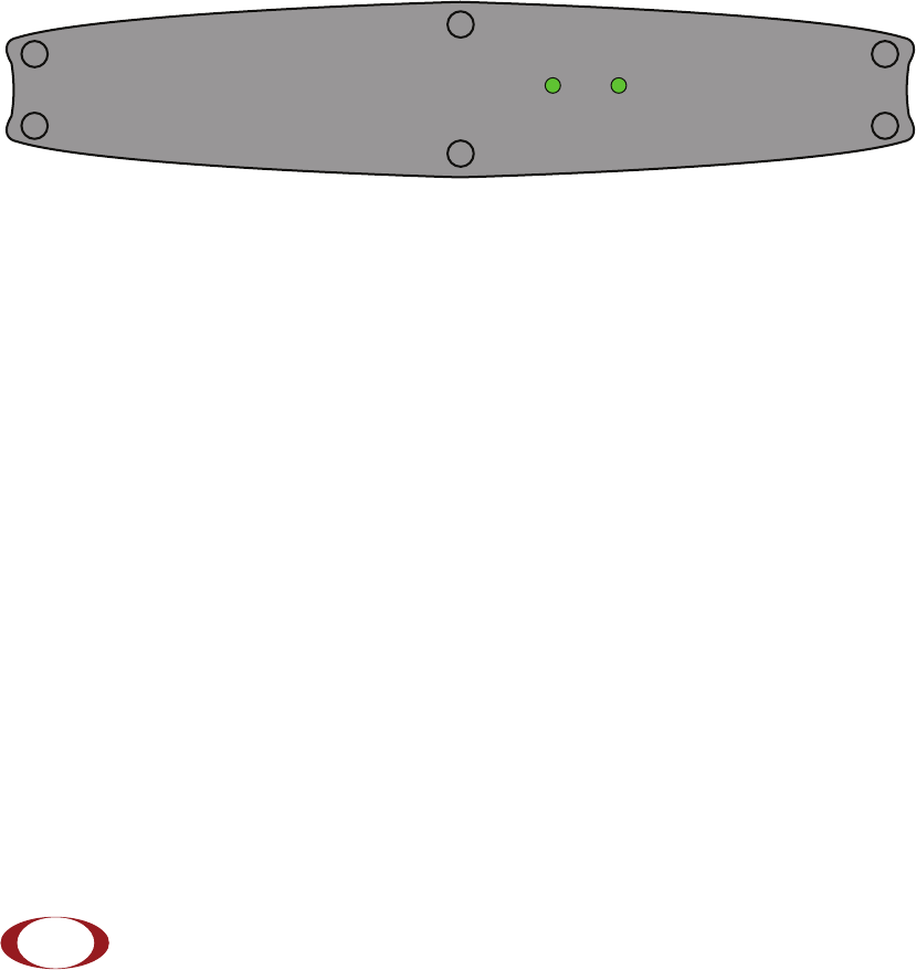
Figure 3 Front View
Figure 4 Rear View
System Specifications
Following are the system specifications for the SCRN frequency bands of operation, system
size, power, environmental requirements, and compliance.
Frequency Bands of Operation
• Transmitter = 2110-2170MHz (Downlink).
• Receiver = 1920-1980MHz (Uplink).
• UMTS Band I monitor mode = 2110-2170MHz.
• GSM low-band listen mode = 925-960MHz.
• GSM high-band listen mode = 1805-1880MHz.
RADIOSTATUS
ANT B ANT A
ETHERNET CONSOLE
Link LED
Activity LED

SpiderCloud Wireless, Inc.
System Specifications
4
Size and Dimensions
• Height:
— 3.81 centimeters (1.5 inches).
— 7.69 centimeters including mount bracket assembly (3.03 inches).
• Width: 19.4 centimeters (7.65 inches).
• Depth: 21.6 centimeters (8.51 inches).
• Weight: 1.41 kilograms without antennas (3.1 pounds).
Power
• The transmitter output power is 100mW radiated power (EIRP) nominal.
• Power over Ethernet (PoE+) can provide 25.5W maximum of delivered power and
a maximum of 600mA at the SCRN.
• The SCRN itself requires 23W of power at 48 volts nominal (41v to 57v).
Environmental Requirements
• Operating temperature range: 0 to 50° C (32 to 122° F).
• Storage temperature range: -40 to 85° C (-40 to 185° F).
• Cooling: The SCRN is cooled mainly through radiated heat loss. This approach
allows for the SCRN to be oriented at any angle.
• Relative humidity: 85% for 48 hours at 85°C, non-condensing.
• Shock and vibration: When the reference oscillator is the “weak-link”, the limits are:
IEC 60068-2-27, test Ea: 1500gn acceleration for 0.5ms duration, half-sine pulse,
three shocks in each direction along three mutually perpendicular axes.
Compliance
• EN 301 489-1.
• EN 301 489-23.
• EN 301 908-1.
• EN 301 908-3.
• EN60950-1 (safety).
SpiderCloud Wireless, Inc.
Hardware Installation Guide for SmartCloud® Radio Node - SCRN 800
5
• IEEE 802.3at PoE+ 25.5W.
• CE Marking.
• RoHS (Directive 2002/95/EC on RoHS).
• R&TTE (Directive 1999/5/EC on R&TTE).
• Directive 2001/95/EC on general product safety (EN 60950-1:2006 - IT Eq’t -
general safety reqs).
• EN 55022:2006 - IT Eq’t - Radio disturbance measurement.
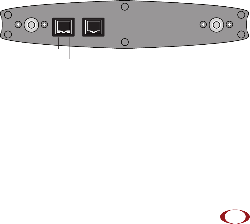
Ports and LEDs
Figure 5 Rear View
• 2 antenna ports labeled ANT B and ANT A. See “Antennas” on page 7 for more
details.
• 1 console port—For administrative CLI access to the system. Access the CLI for
advanced diagnostics, troubleshooting, and monitoring. This RS-232 serial console
port has an RJ45 connection with these settings:
— Baud rate: 115,200 bps.
— Data bits: 8.
— Stop bits: 1.
— Parity: none.
— Flow control: none.
ANT B ANT A
ETHERNET CONSOLE
Link LED
Activity LED
SpiderCloud Wireless, Inc.
Ports and LEDs
6
• 1 10/100 Ethernet port. Attach a category 5 cable to this port. Figure 5 shows the
10/100 port with the tab facing down. There are two LEDs on the connector:
Link—On the lower-right corner of the RJ45. Steady green state indicates a normal
Layer 2 link connection has been established.
Activity—On the lower-left corner of the RJ45. Yellow blinking indicates data
activity.
Figure 6 Font View
There are two LEDs on the front of the system: Status and Radio.
LED descriptions:
•Status—The overall status of the system. There are five states for this LED:
— Quick blinking green: The system is booting up.
— Solid green: When the operating system starts successfully, the LED turns to
solid green indicating normal behavior.
— Red: If the operating system cannot boot up, the LED turns to solid red
indicating a fault condition.
— Slow blinking green: The system is administratively disabled.
— Off: The system is powered down.
•Radio—The radio indicator. There are four states for this LED:
— Solid green: The radio is in normal UMTS transmitting mode.
— Blinking green: The radio is in receiving mode (network monitoring).
— Red: A radio fault has occurred.
— Off: The radio is idle (not transmitting, not receiving).
RADIOSTATUS
SpiderCloud Wireless, Inc.
Hardware Installation Guide for SmartCloud® Radio Node - SCRN 800
7
Antennas
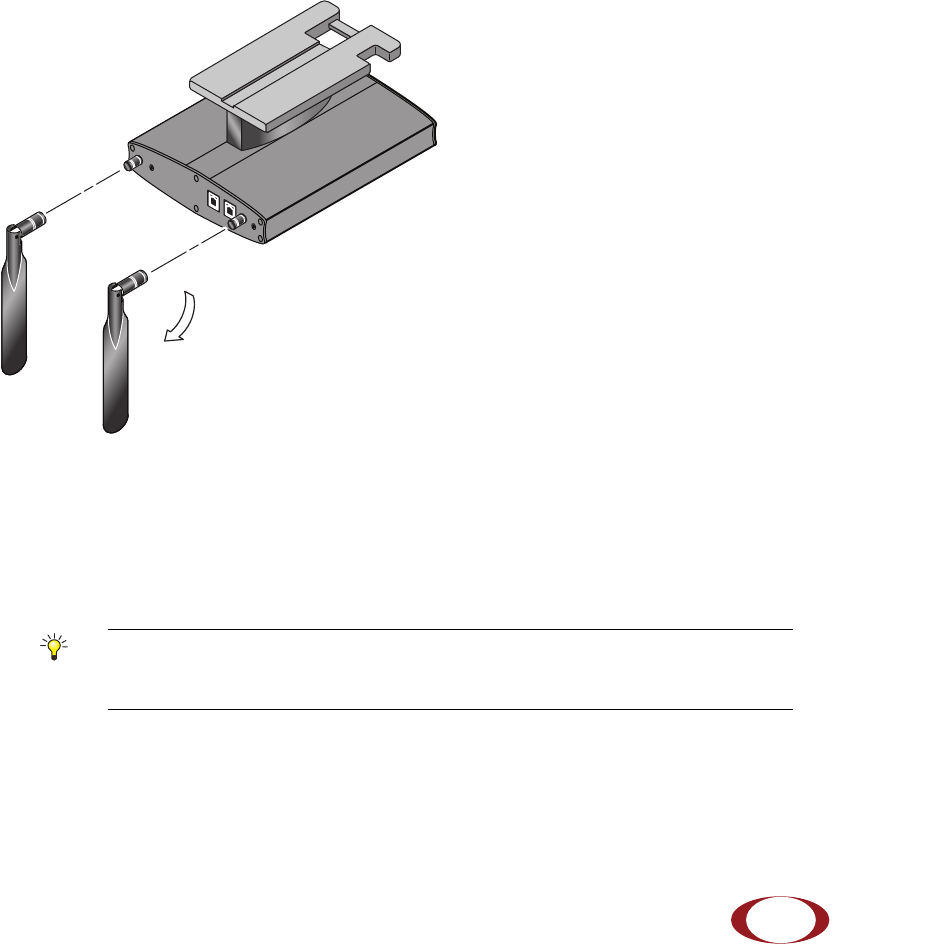
Figure 7 shows the antennas for the UMTS Band I Radio Node. These antennas have a
thread-on reverse-polarity TNC connector.
Figure 7 Antennas Rotate 90 Degrees
Vertically-polarized, omindirectional antennas are provided. They radiate power in a plane
normal to their length—horizontal radiation from vertically-oriented antennas.
The physical location of the SCRN in a building is not critical because the SCRN operates over
a licensed band. However, coverage area is very important. Place the SCRN units at strategic
points for best coverage.
Tip
To maximize antenna transmission, SpiderCloud Wireless, Inc. recommends
that you should not install the SCRN underneath or inside a metallic
enclosure.
Swivels 900
ANT BANT A
ETHERNETCONSOLE
SpiderCloud Wireless, Inc.
Installation and Mount Bracket Assembly
8
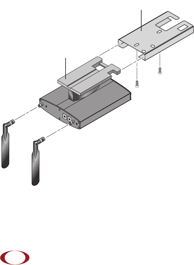
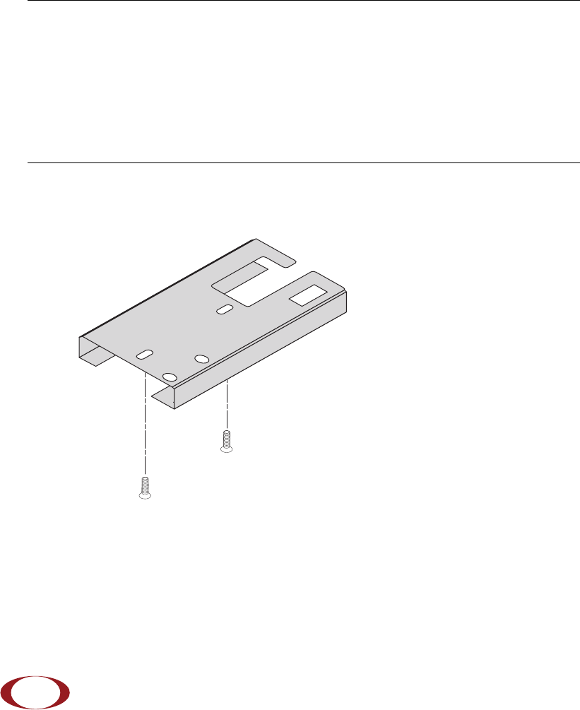
Installation and Mount Bracket Assembly
The SCRN has a pedestal base that slides into a long “U” shaped bracket for ceiling or wall
mounting. SpiderCloud pre bolts the pedestal base onto the extrusion plate on the SCRN.
However you must attach the pedestal base to the mount bracket as shown in the following
diagram:
Figure 8 Pedestal Base Slides into Mount Bracket
ANT BANT A
ETHERNETCONSOLE
Mount Bracket
Pedestal Base
SpiderCloud Wireless, Inc.
Hardware Installation Guide for SmartCloud® Radio Node - SCRN 800
9
Installation Procedure
Follow these steps to install the SCRN:
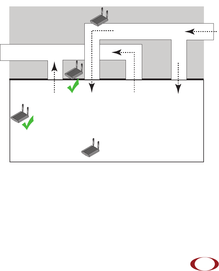
Step 1 Choose a location for the SCRN. The unit can be installed in a wide range of
locations including walls, ceilings, and plenum spaces. Follow the installation
guidelines for choosing appropriate mounting locations for the unit.
–Locate SCRN units at least 5 meters from an external wall. This distance
maximizes indoor coverage and minimizes RF leakage outside the building.
–SCRN Separation. Use the following table to determine the maximum distance
between SCRN units. Using distances greater than this may affect coverage or
system performance.
RADIO
STA
TUS
RADIO
STA
TUS
Dead / Non-Circulating
Airspace
Living / Working Space of a Typical
Commercial Building
Drop Ceiling
Wall
X
X
Forced-Air Supply
Forced-Air Return
RADIO
STA
TUS
RADIO
STA
TUS
SpiderCloud Wireless, Inc.
Installation and Mount Bracket Assembly
10
Step 2 Screw the mount bracket assembly to a wall or ceiling. The screw holes are
sized for an M4 (#10) screw. Ensure the screws have a snug fit onto the studs,
sheetrock, or whatever material you are bolting to:
Table 1 Recommended Separation Distances
Type of Building
Max Recommended SCRN
Separation (m)
Warehouses and large open-spaced buildings 70 m
Open-plan offices 45 m
Closed-plan offices (e.g., individual rooms - plasterboard) 30 m
Closed-plan offices (e.g., individual rooms - stone/brick/
concrete)
20 m
SpiderCloud Wireless, Inc.
Hardware Installation Guide for SmartCloud® Radio Node - SCRN 800
11
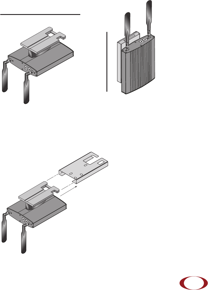
Step 3 Attach the antennas to the TNC connectors on the SCRN. If the SCRN is
mounted on the ceiling, flip the antennas pointing downward. If mounted on the
wall, flip the antennas pointing upward:
Step 4 Slide the pedestal base of the SCRN into the groove opening in the mount
bracket. When the pedestal reaches the bottom of the trough, a spring clip will
snap the unit into place:
ANT BANT A
ETHERNETCONSOLE
ANT BANT A
ETHERNET CONSOLE
Ceiling
Wall
Mount Bracket
Pedestal Base
ANT BANT A
ETHERNETCONSOLE
SpiderCloud Wireless, Inc.
Installation and Mount Bracket Assembly
12
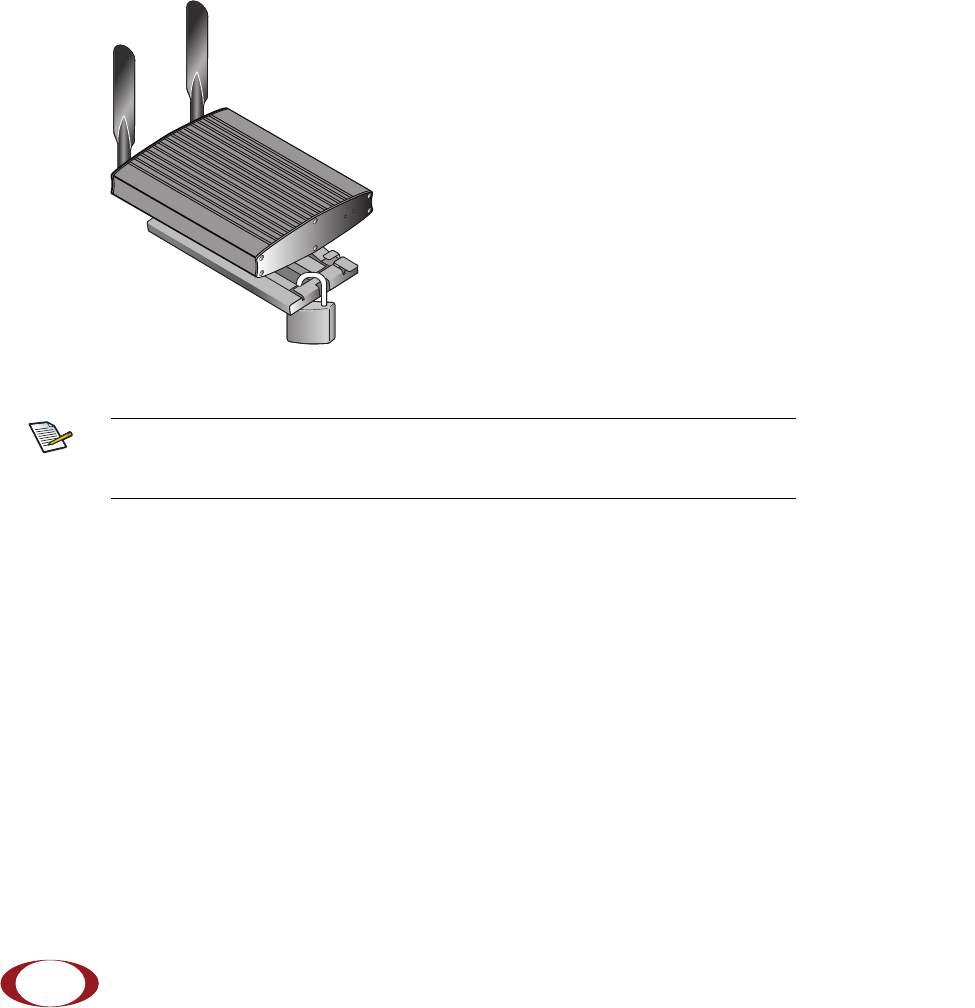
Step 5 Physically secure the SCRN. Locate the bar between the two “U” shaped
brackets. Clamp a padlock or cable tie wrap through the two cutout holes and
across the bar:
Step 6 Attach a powered Ethernet cable. The SCRN receives its power source over
powered Ethernet. If your wiring closet does not have existing PoE+ equipment,
SpiderCloud provides a PoE+ power injector for the SCRN. See “PoE+” on
page 15.
Note
The lock in the above figure is shown schematically. The orientation is for
illustration purposes (not accurate) since the bracket is wall or ceiling
mounted.
RADIO
STA
TUS
SpiderCloud
Wireless
SCRN800
SpiderCloud Wireless, Inc.
Hardware Installation Guide for SmartCloud® Radio Node - SCRN 800
13
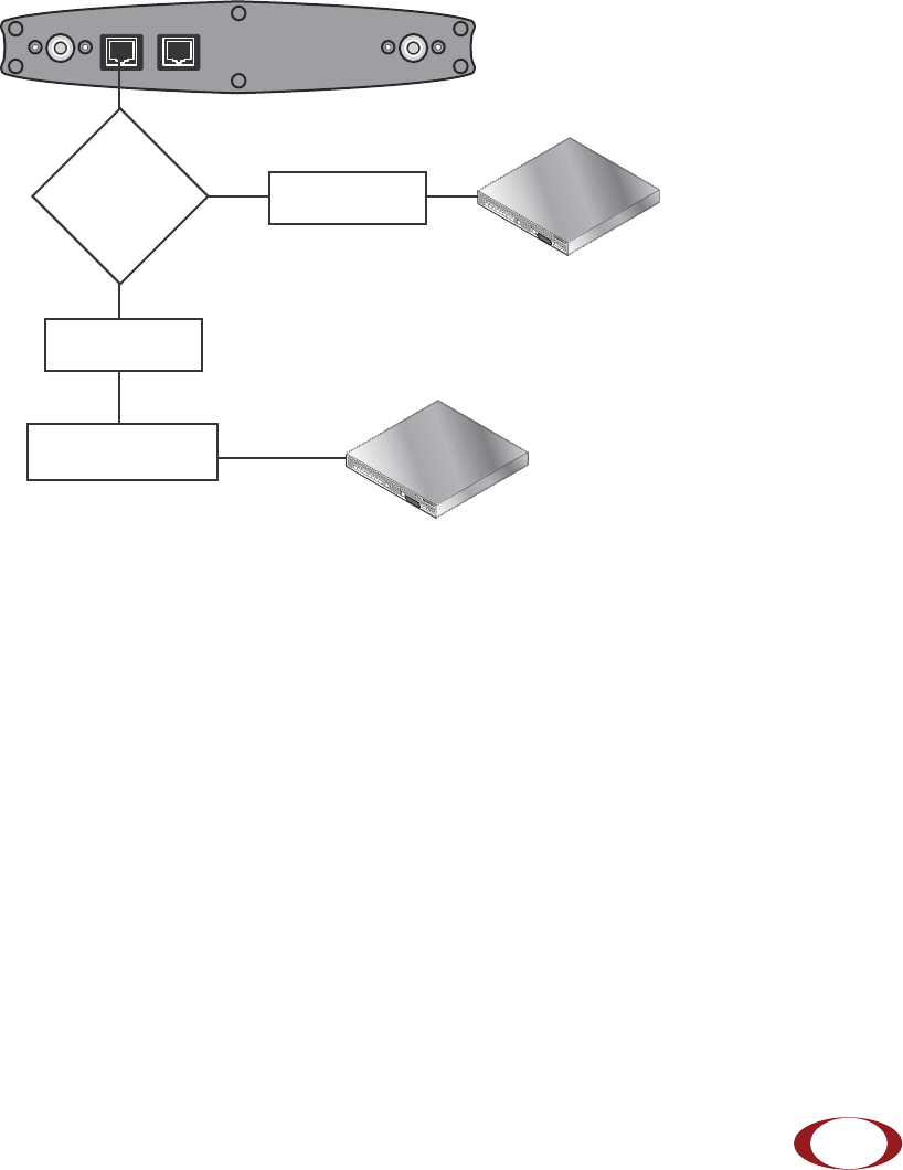
Step 7 The SCRN boots up and attempts to connect to the SCSN. See “Boot
Sequence and SCSN Communication” on page 16 for details.
SCSN 8000
PoE Switch
Out
In
ANT B ANT A
ETHERNET CONSOLE
SCSN 8000
PoE Switch or
PoE Injector
PoE Injector
Non PoE Switch
SpiderCloud Wireless, Inc.
Installation and Mount Bracket Assembly
14
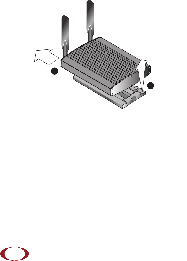
Detaching the SCRN from the Mount Bracket
To remove the SCRN from the bracket assembly:
Step 1 Lift up the release tab on the under side of the SCRN.
Step 2 Slide the SCRN out of the mount bracket.
RADIO
STATUS
SpiderCloud
Wireless
SCRN800
Lift tab up
Slide RN out
of bracket
1
2

SpiderCloud Wireless, Inc.
Hardware Installation Guide for SmartCloud® Radio Node - SCRN 800
15
PoE+
The SCRN is fully compliant with the IEEE 802.3at Power Over Ethernet (PoE+) specification.
The SCRN gets its power from a standard PoE+ switch (typical) or injector.
Per 802.3at, standard CAT-5/5e or better twisted-pair cable with a maximum length restriction
of 100 meters (328 feet) should be used for PoE+. This restriction minimizes power loss
between the PoE+ power source and the SCRN.
SpiderCloud provides an optional single-port PoE+ injector in the accessory kit. Use this
injector only when a PoE+ Ethernet switch is not available.
Figure 9 PoE+ Injector
To install the injector:
Step 1 Attach the injector’s power cord to a power source.
Step 2 Connect an unpowered Ethernet cable from a switch to the IN port on the
injector.
Step 3 Connect an Ethernet cable from the injector’s OUT port to the SCRN. The
injector will now inject power onto a pair of wire pairs in the cable. The SCRN
will expect a nominal 48V DC input (57V max) from the PoE+ injector. The
Phihong PoE+ power injector supplies 57V maximum typically.
Note
The SCRN can accept power on used or un-used pairs. Power distribution is
over two pairs of the four available pairs in Cat 5.
OUT IN
CONNECTPoEPLUSON
SpiderCloud Wireless, Inc.
Boot Sequence and SCSN Communication
16
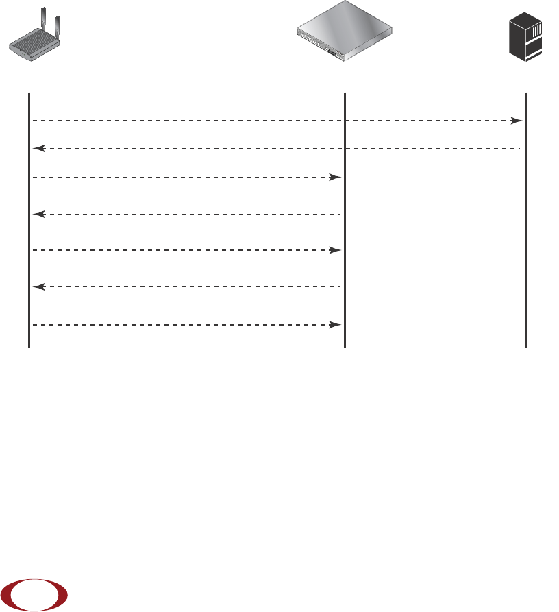
Boot Sequence and SCSN Communication
On initial boot, the SCRN performs the following boot sequence and communicates with the
SCSN. This sequence takes about 1 minute to complete. When completed, all devices are
reachable:
Figure 10 SCRN Boot Sequence
Sequence description:
1. When the SCRN is powered on, the device sends a DHCP Request to the network
DHCP server to get IP information.
2. The DHCP server is configured to use vendor option 43. The server responds with the
IP addresses of the SCRN and the SCSN (the master of the SCRN).
The following example shows a sample configuration from a DHCP server:
option space SPIDERCLOUD;
option SPIDERCLOUD.access-controller code 102 = string;
option SPIDERCLOUD.access-controller "10.1.30.99;";
SCRN 800
SCSN 8000 DHCP Server
RADIO
STATUS
DHCP Request for IP address
DHCP Response (RN IP, Controller IP)
Mount package, join the network
Join Request
Arrival sequence begins
Join Response (Join Grant, Redirect, Denied)
Send SpiderCloud software package

SpiderCloud Wireless, Inc.
Hardware Installation Guide for SmartCloud® Radio Node - SCRN 800
17
3. Using its own IP address, the SCRN sends a Join Request message to the SCSN.
The SCRN seeks to join the cellular network.
4. The Join Response from the SCSN will be one of the following:
—Join Grant: Permit the SCRN to join the SCSN.
—Redirect: Redirect the SCRN to join a different SCSN, if you have multiple
SCSN units configured in the network.
—Denied: The security signature on the SCRN does not match what the SCSN
expects. The client is untrusted and treated as a rogue device.
5. The arrival sequence begins. Based on the configuration of the SCRN, the SCRN will
join the system and get its configuration. The SCSN sends the SpiderCloud software
image (the system image and configuration settings) to the SCRN.
6. The SCRN reboots and mounts the SpiderCloud software image as a RAM-based file
system.
7. The SCRN contacts the SCSN and joins the network.
Related Documents
See the following documents for more information:
•SmartCloud® CLI Quick Start Guide Release 1.4 to configure the software
environment and internetworking between the SCSN and SCRN devices.
•See the Hardware Installation Guide for SmartCloud® Services Node - SCSN 8000
for hardware specifications and installation instructions.
•SCOS NB Data Model Reference for reference details about Operational Mode and
Configuration Mode commands.

SpiderCloud Wireless, Inc.
Hardware Installation Guide for SmartCloud® Radio Node - SCRN 800
18

SpiderCloud Wireless, Inc. 19
B
baud rate 5
boot sequence 16
C
CE 5
compliance 4
console port 5
cooling 4
D
data bits 5
depth 4
DHCP 16
E
EIRP 4
F
flow control 5
frequency bands of operation 3
front view 3
G
GSM 3
H
height 4
L
LEDs 5
M
mount bracket 8
O
operating temperature range 4
P
parity 5
pedestal base 8
PoE+ 15
ports 5
R
Radio LED 6
rear view 3
receiver 3
relative humidity 4
Reverse Polarity-TNC 7
RoHS 5
Index
