Spinal Modulation orporated MN0200 Implantable Neurostimulator User Manual LP0275 Rev B September 2011
Spinal Modulation, Incorporated Implantable Neurostimulator LP0275 Rev B September 2011
Revised user manual

Axium™NeurostimulatorSystem
PhysicianImplantManual
SpinalModulation,Inc.
1135O’BrienDrive
MenloPark,CA94025
USA
Copyright©September2011bySpinalModulation,Inc.AllRightsReserved.Noportionofthismanualmaybereproducedor
transmittedinanyformorbyanymeans,electronicormechanical,includingphotocopying,recording,oranyinformation
storageandretrievalsystems,withouttheexpresswrittenpermissionofSpinalModulation,Inc.
LP0275RevB,September2011
TM
SpinalModulation,Inc. PhysicianImplantManual
i
Contents
ExplanationofSymbolsonProductorPackageLabeling................................................. 4
INTRODUCTION ............................................................................................................................ 5
SystemOverview ............................................................................................................ 6
IndicationsforUse .......................................................................................................... 7
Contraindications............................................................................................................ 7
SYSTEMDESCRIPTION.................................................................................................................... 7
TrialNeurostimulator(TNS) ............................................................................................ 9
ImplantableNeurostimulator(INS) ................................................................................. 9
ImplantLeads/TrialLeads/LeadExtension..................................................................10
ConnectorCableKit .......................................................................................................10
LeadAccessories ............................................................................................................10
ImplantationTools.........................................................................................................11
AdditionalAccessories ...................................................................................................11
ClinicalProgrammerandPatientProgrammer ...............................................................11
SterilizationInformation ................................................................................................12
StorageConditions.........................................................................................................12
ProductMaterials ..........................................................................................................12
SAFETYINFORMATION ..................................................................................................................13
• GeneralWarnings .................................................................................................13
• Warnings–ForUseinHomeorWorkEnvironments.............................................15
• Precautions ...........................................................................................................16
AdverseEvents ..............................................................................................................17
IMPLANTINGTHENEUROSTIMULATORSYSTEM ...................................................................................18
• PrecautionsfortheImplantProcedure .................................................................18
SelectionofNeurostimulatorTrialApproach .................................................................19
PreparingthePatientandDevicesforUse .....................................................................20
PlacingtheLead .............................................................................................................20
IntraoperativeTesting....................................................................................................25
RemovingtheDeliverySystemComponents–PercutaneousLeadTrial.........................26
LeadAnchoring–PercutaneousLeadTrial .....................................................................28
NeurostimulationTrial–PercutaneousLeadTrial...........................................................28
RemovingTrialLead–PercutaneousLeadTrial ..............................................................29
RemovingtheDeliverySystemComponents–ImplantLeadTrialOnly..........................29
LeadAnchoring ..............................................................................................................31
SpinalModulation,Inc. PhysicianImplantManual
ii
PercutaneousExtensionTunneling–ImplantLeadTrialOnly ........................................32
RemovingLeadExtension–ImplantLeadTrialOnly ......................................................33
CreatingtheINSPocket–Implant..................................................................................34
LeadorExtensionTunneling ..........................................................................................35
ConnectingLeadtoExtension ........................................................................................35
ConnectingtheINS.........................................................................................................36
ImplantingtheINS .........................................................................................................37
CheckingSystemIntegrity..............................................................................................38
CompletingtheProcedure .............................................................................................38
REPLACINGANINS ......................................................................................................................38
DisposingofanExplantedDevice...................................................................................39
APPENDIXA:TRIALLEADKIT/IMPLANTLEADKIT .............................................................................40
HowSupplied.................................................................................................................40
PackageContents...........................................................................................................40
DeviceSpecification .......................................................................................................41
APPENDIXB:TRIALNEUROSTIMULATOR ..........................................................................................42
DeviceDescription .........................................................................................................42
PackageContents...........................................................................................................42
DeviceSpecifications .....................................................................................................42
Handling ........................................................................................................................43
APPENDIXC:IMPLANTABLENEUROSTIMULATOR ................................................................................44
HowSupplied.................................................................................................................44
DeviceDescription .........................................................................................................44
PackageContents...........................................................................................................44
DeviceSpecifications .....................................................................................................44
Handling ........................................................................................................................45
DeviceLongevity............................................................................................................45
COMPANYANDAUTHORIZEDREPRESENTATIVECONTACTINFORMATION ..................................................46

SpinalModulation,Inc. PhysicianImplantManual
4
ExplanationofSymbolsonProductorPackageLabeling
ModelNumber
LotNumber
ConsultInstructionsforUse
ReadtheManual
Donotresterilize
SingleUseOnly
SterilizedbyEthyleneOxideGas
UseByYYYY‐MM
Opensterilepouchbypeelingpouchcorner
Opensteriletraybypeelingtraycorner
Manufacturer
ManufacturingDate
Warning
Standby
Caution
Notwaterproof
AppliestotheProgrammerwhenitisnotinitscarryingcase

SpinalModulation,Inc. PhysicianImplantManual
5
Limitedwaterproof.AppliestotheTNS
AppliestotheProgrammerinitscarryingcase
ContentsofPackageareNon‐Sterile
KeepDry
Storagetemperature
Storebetween10%and90%humidity
SterileComponents
Storebetween0%and93%humidity
TNSandProgrammers
Thedeviceisaradiotransmitter
Magnet.ShowsthelocationoftheProgrammermagnet.
AuthorizedEuropeanRepresentative
RFOperatingFrequencies.Nearbyequipmentemittingstrongmagneticfieldscaninterferewith
RFcommunication,eveniftheotherequipmentcomplieswithCISPRemissionrequirements.The
operatingcharacteristicsareasfollows:
MICS/MedRadioband:402‐405MHz.Theeffectiveradiatedpowerisbelowthelimitsas
specifiedin
Europe:ENETSI301839‐2
USAFCC47CFRPart95;95.601‐95.673SubpartE,95.1201‐95.1219
FCCID:Y8L‐MN0200
Thisdevicemaynotinterferewithstationsoperatinginthe400.150–406.000MHzbandinthe
MeteorologicalAids,MeteorologicalSatellite,andEarthExplorationSatelliteServicesandmust
acceptanyinterferencereceived,includinginterferencethatmaycauseundesiredoperation.
Introduction
ThismanualdescribestheAxium™NeurostimulatorSystem,includinginstructionsfor
implantation.Fordetailedoperationandclinicalprogramminginstructions,refertotheClinical
ProgrammerManual.
SpinalModulation,Inc. PhysicianImplantManual
6
SystemOverview
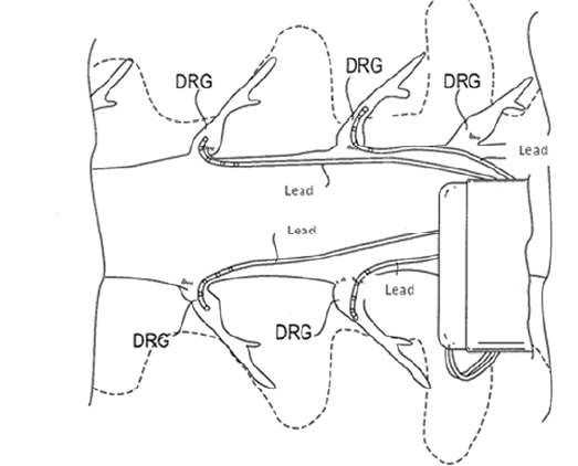
TheAxium™NeurostimulatorSystemconsistsofanImplantableNeurostimulator(INS)device,
TrialNeurostimulator(TNS)device,aClinicalProgrammer,aPatientProgrammer,oneormore
leadswhichmaybeusedincombinationwithaleadextensionandtheaccessoriesandtools
usedforimplantingthesystem.TheTNSorINSisconnectedtoleadsplacedwithintheepidural
spacenearthedorsalrootganglion(DRG).Uptofourleadsmaybeplacedandconnectedto
theneurostimulatortoprovidestimulation.
PatientswhoareindicatedfortheAxium™ImplantableNeurostimulator(INS)Systemwillfirst
undergoatemporarytrialperiodusinganexternalTrialNeurostimulator(TNS)System
connectedtoimplantedleads.Ifboththeclinicianandpatientbelievethatsufficientpainrelief
wasachieved,thenthepatientwillbescheduledforanimplant,inwhichtheINSwillbe
implanted.
NOTE:Inthismanualthegeneralabbreviation“NS”isusedforinformationwhichappliesto
bothTNSandINS.Inallothercasesthespecificabbreviations“TNS”or“INS”areused.

SpinalModulation,Inc. PhysicianImplantManual
7
IndicationsforUse
TheAxium™NeurostimulatorSystemisindicatedasanaidinthemanagementofchronic
intractablepainofthetrunkand/orlimbs.
Contraindications
PatientscontraindicatedfortheAxium™NeurostimulatorSystemarethosewho:
• Haveanactiveimplantablemedicaldeviceincludingbutnotlimitedtocardiac
pacemakersandcardiacdefibrillators
• Areunabletooperatethesystem
• Arepoorsurgicalrisks
• Arepregnant
• Areundertheageof18
SystemDescription
TheAxium™NeurostimulatorSystemconsistsofthefollowingcomponents:
Component
Name
Model
Numbers
PackageContentInstructionsforUse
Trial
Neurostimulator
MN10100
MN20100
• TrialNeurostimulatorTrialNeurostimulator
Manual
Implantable
Neurostimulator
MN10200
MN20200
• ImplantableNeurostimulator
• LeadPortPlugs(3)
• TorqueWrench
• SterileMagnetSleeve
• MedicalAlertCard
PhysicianImplant
Manual
TrialLeadKit
(lengthincm
specifiedby‐XX)
MN10350‐XX
MN20350‐XX
• TrialLead
• 22cmSmallCurveDeliverySheath
• 22cmBigCurveDeliverySheath
• Guidewire
• ComplexCurvedStylet
• 4.5”14GDeliveryNeedle
• SoftTissueAnchor(2)
PhysicianImplant
Manual

SpinalModulation,Inc. PhysicianImplantManual
8
Component
Name
Model
Numbers
PackageContentInstructionsforUse
ImplantLeadKit
(lengthincm
specifiedby‐XX)
MN10450‐XX
MN20450‐XX
• ImplantLead
• 22cmSmallCurveDeliverySheath
• 22cmBigCurveDeliverySheath
• Guidewire
• ComplexCurvedStylet
• 4.5”14GDeliveryNeedle
• SoftTissueAnchor(2)
PhysicianImplant
Manual
ConnectorCable
Kit
MN11350
MN21350
• ConnectorCable
• LeadIdentifiers(3)
PhysicianImplant
Manual
TunnelingToolKit
30/51cm
MN11900
MN21900
MN12200
MN22200
• Tunnelingtool30/51cm
• Straw
• TrocarTip
• PencilTip
• INSSizer
• PortPlugs(3)
• TorqueWrench
PhysicianImplant
Manual
Clinical
Programmer
MN10700
MN20700
• ClinicalProgrammer
• ExternalMagnet
• ProgrammerCharger
• CarryingCase
ClinicalProgrammer
Manual
Patient
Programmer
MN10600
MN20600
• PatientProgrammer
• ExternalMagnet
• ProgrammerCharger
• CarryingCase
• MedicalAlertCard
PatientProgrammer
Manual
AuxiliaryMagnet
Kit
MN13300
MN23300
• AuxiliaryMagnetAncillaryItemsManual
Programmer
ChargerKit
MN13400
MN23400
• ProgrammerChargerAncillaryItemsManual
Programmer
CarryingCase
MN13500
MN23500
• ProgrammerCarryingCaseAncillaryItemsManual
LeadAccessories
Kit
MN12050
MN22050
• 4.5”14GDeliveryNeedle
• 6.0”14GDeliveryNeedle
• SoftTissueAnchor
• ComplexCurvedStylet
• 30cmBigCurveDeliverySheath
• 30cmSmallCurveDeliverySheath
PhysicianImplant
Manual
SpinalModulation,Inc. PhysicianImplantManual
9
Component
Name
Model
Numbers
PackageContentInstructionsforUse
22cmSmallCurve
DeliverySheathKit
MN12150
MN22150
• 22cmSmallCurveDeliverySheaths(2)PhysicianImplant
Manual
22cmBigCurve
DeliverySheathKit
MN13650
MN23650
• 22cmBigCurveDeliverySheaths(2)PhysicianImplant
Manual
4.5”NeedleKitMN11700
MN21700
• 4.5”14GDeliveryNeedlePhysicianImplant
Manual
LeadExtensionKit
(lengthincm
specifiedby‐XX)
MN10550‐XX
MN20550‐XX
• LeadExtension50cm
• TorqueWrench
PhysicianImplant
Manual
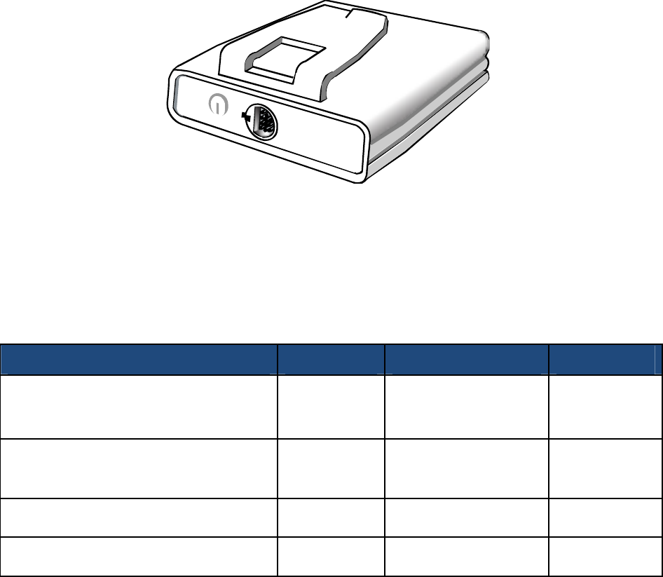
TrialNeurostimulator(TNS)
TheexternalTNSdeviceconnectstotheTrialLead(s)orLead
Extensionsandiswornbythepatientforupto30daysduring
thetrialperiod.TheTNSdevicehasabeltclipforthepatient’s
convenience.
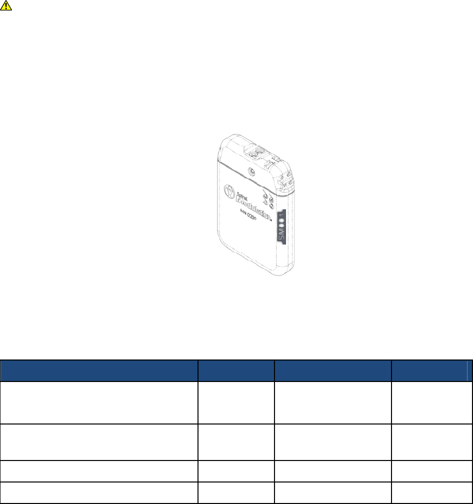
ImplantableNeurostimulator(INS)
TheAxium™ImplantableNeurostimulator(INS)isanon‐rechargeable,4channelelectronic
device.Itusesmicroelectroniccircuitry,poweredbyahermeticallysealedbattery,togenerate
apulsedwaveformtostimulateneuraltissue.Theelectroniccircuitryandbatteryarehoused
inahermeticallysealedtitaniumcase.
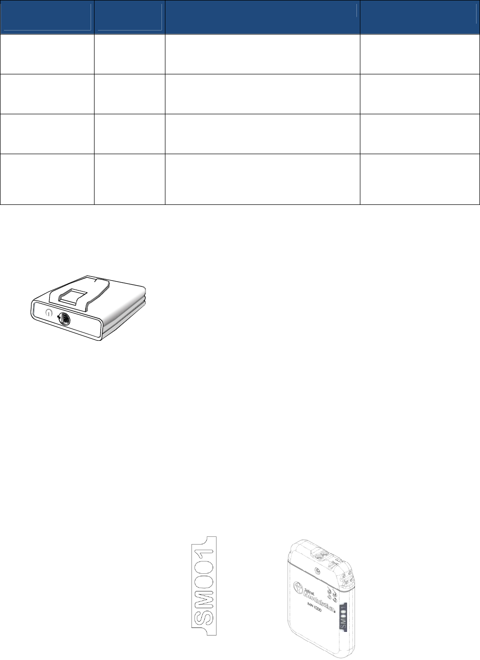
Eachneurostimulatorhasauniqueinternalidentifierthatallowsthephysiciantoidentifythe
typeofdevicethroughanX‐ray.Theradiopaqueidentifierinsidethecaseallowsidentification
ofboththedevicemanufacturerandmodelnumberusingstandardx‐rayequipment.Forthe
Axium™Neurostimulator,thecodeisSM001whichidentifiesSpinalModulationasthe
manufacturerandMN10200/MN20200asthemodelnumber.

SpinalModulation,Inc. PhysicianImplantManual
10
TheINSispackagedinasealedinnertraywithinasealedoutertray.
ImplantLeads/TrialLeads/LeadExtension
TheLeadKitscontaintheLeadsandtheindividualdeliverydevicesthatarerequiredfortheir
placement.
CAUTION:ThetemporarilyplacedTrialLeadsareintendedforuseforupto30days.
• Implant/TrialLeads:TheLeadsaredesignedforpercutaneousintroductionintothebody
usingaspecialneedleandasetofcustomdeliverytoolsprovidedintheirrespectivekits.
EachLeadisfittedwithfourcylindricalelectrodesspacedatequalintervalswhichare
intendedtoprovidestimulationatthetargetdorsalrootganglion(DRG).EachLeadis
packagedwithaComplexCurvedStyletinsertedintotheLeadandtheLeadispre‐loaded
intoa22cmSmallCurveDeliverySheathforthephysician’sconvenience.
• LeadExtension:TheLeadExtensionconsistsofasiliconeportheaderthatacceptsthe
SpinalModulationTrialLeadandImplantLead.Itisintendedtoextendthelengthofthe
leadandprovideaconnectionbetweentheleadandtheConnectorCableortheleadand
theImplantableNeurostimulatorSystem.TheLeadExtensionisintendedforchronic
implantationasacomponentoftheAxium™NeurostimulatorSystem.
ConnectorCableKit
TheConnectorCableconnectstheLeadsorLeadExtensiontotheexternalTNS.
• ConnectorCable:TheConnectorCableispackagedseparatelyfromtheLeadandLead
ExtensionKit.TheConnectorCableincludesaconnectorand2extensioncablesforuse
asneeded.
• LeadIdentifiers:TheLeadIdentifiersaresmallbentwiresthatcanbeinsertedintothe
proximalstyletlumenintheleadsandareindividuallycoloredtoidentifytheleads.
LeadAccessories
• Small/BigCurveDeliverySheath:TheDeliverySheathsareintendedtoallowpassageof
theleadpercutaneouslyintotheepiduralspace.Thelabeledlengthofthesheathisthe
distancefromthehubtothepre‐shapedtipandthelengthofthecurveatthetipis
approximately2mmfortheSmallCurveandapproximately8mmfortheBigCurve.
• ComplexCurvedStylet:TheComplexCurvedStyletisintendedtoassistinsteeringand
positioningtheleadwithintheepiduralspace.TheComplexCurvedStylethasbeenpre‐
insertedintotheLeadforthephysician’sconvenience.
• 14GDeliveryNeedles:TheDeliveryNeedleisintendedtoaccesstheepiduralspace,
providingaconduitforlead,guidewireanddeliverysheathplacement.
• Guidewire:TheGuidewireisintendedtoverifythattheneedleisintheepiduralspace
afterusingalossofresistancetechnique.
SpinalModulation,Inc. PhysicianImplantManual
11
• SoftTissueAnchor:TheSoftTissueAnchorsareintendedtoanchortheLeadinthesoft
tissueorontheskinsurfaceproximaltothedistalcontactsoftheLead.
ImplantationTools
• TunnelingTool:ThetunnelingtoolisusedtoprovideaconduitfortheTrialLead,Implant
Lead,orLeadExtensiontotheINSorawayfromthemidlineofthespine.Itispackaged
with2exchangeabletips:abluntpenciltipandasharptrocartip.Astrawisslidoverthe
tunnelingtoolandwhenthesteelhandleisremoved,thestrawprovidestheconduitfor
tunneling.
• INSSizer:TheINSSizerisapproximatelythesamesizeastheINSandallowsthephysician
toproperlysizetheINSpocket.
• PortPlugs:TheportplugsareusedtofillunusedportsintheINS.Theyarepackagedwith
theINS,butspareportplugsarealsopackagedwiththeTunnelingToolKitsforthe
convenienceofthephysician
AdditionalAccessories
• SterileMagnetSleeve:Themagnetisplacedinthesterilesleevetoallowittobeused
duringtheimplantationoftheINS.
• MedicalAlertCard:IdentifiesthepatientasauseroftheNeurostimulationSystem.
• ProgrammerCharger:TobeusedwiththeClinicalorPatientProgrammerstochargethe
batteryorallowuseoftheProgrammerswhilepluggedintostandardelectricaloutlets.
• ProgrammerCarryingCase:ProtectstheProgrammersfromwater.
• AuxiliaryMagnet:AllowstheusertotheturntheNSofforactivatesRFtoallowtheuserto
communicatewiththeNS.
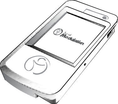
ClinicalProgrammerandPatientProgrammer
TwoprogrammersareavailabletointeractwiththeNSdevice.
1. TheClinicalProgrammerisusedtoprogramthe
stimulationparametersforboththeTNSand
theINS.Theinstructionsforprogrammingthe
TNSandINSdevicesarethesame.TheClinical
Programmerisusedbythephysicianorclinical
staff.
2. ThePatientProgrammerallowsthepatientto
adjustthestimulationsettingsoftheTNSand
INSdeviceswithinlimitspresetbytheclinician.
ThePatientProgrammeralsoallowsthepatient
toturnstimulationoff,ifnecessary.

SpinalModulation,Inc. PhysicianImplantManual
12
Note:FordetailedinformationandinstructionsrelatedtotheClinicalandPatient
ProgrammerandtheTrialNeurostimulator,refertotherespectiveusermanuals.
SterilizationInformation
Single‐use,steriledevice‐ThesterilecomponentsoftheAxium™NeurostimulatorSystemare
providedsterileinadoublepouchortrayassemblyandareintendedforsingleuseonly.An
expirationdate(or“use‐before”date)ismarkedonthelabelofeachpackage.Useproper
steriletechniquestoopenthepackaging.
WARNING:Donotresterilizeorreuseanydevicesforanyreasonbecauseofriskof
infectiontothesubjectandmalfunctionofthedevices.
Sterilization–TheSpinalModulationINS,TrialLeadKit,ImplantLeadKit,LeadExtensionKit,
LeadAccessoriesKitandTunnelingToolKitshavebeensterilizedusingethyleneoxide(EO)gas.
StorageConditions
StoreallsterileproductincludingtheINS,Leads,andLeadAccessoriesKitsasfollows:
StorageTemperature–Storecomponentsbetween14°F(‐10°C)and122°F(50°C).
Temperaturesoutsidethisrangemaydamagethecomponents.Ifatemperaturedeviationhas
occurred,donotusetheproduct.
StorageHumidity–Storecomponentsbetween10%and90%humidity.
StorageEnvironment–Storecomponentsandtheirpackagingwheretheywillnotcomein
contactwithliquidsofanykind.
ProductMaterials
PortionsoftheAxium™NeurostimulatorSystemwillcomeincontactwithbodilytissues.
WARNING:Neurostimulationsystemshavematerialsthatcomeincontactwithtissue.A
physicianshoulddeterminewhetherornotapatientmayhaveanallergicreactionto
thesematerialsbeforethesystemisimplanted.
Thefollowingmaterialsareimplantedandcomeincontactwithtissue:
• Platinumiridium• StainlessSteel
• Polyurethane• MP35N(nickel‐cobalt‐chromium‐molybdenumalloy)
• Titanium • PEEK(polyetheretherketone)
• Epotek• PFA(perfluoroalkoxycopolymerresin)
• Siliconerubber• PMMA[poly(methylmethacrylate)]

SpinalModulation,Inc. PhysicianImplantManual
13
SafetyInformation
GeneralWarnings
ThefollowingwarningsapplytotheuseoftheAxium™NeurostimulatorSystem:
• ExternalDefibrillators–Safetyforuseofexternaldefibrillatordischargesonapatient
receivingneurostimulationhasnotbeenestablished.
• MagneticResonanceImaging–Thepatientshouldbeadvisedtonotundergoany
electivemagneticresonanceimaging(MRI)withthesysteminplace.UseofMRIinthe
vicinityofthelead(s)mayresultinforcefuldislodgmentofthelead(s),ordamagetothe
Neurostimulator.Ifavoltageisinducedthroughthelead,itmaycauseuncomfortable
(“jolting”or“shocking”)levelsofstimulationorinjurytothepatient.
• UltrasonicScanning–Ultrasonicequipmentmaycausemechanicaldamagetothelead
ifuseddirectlyoverthesite.
• ElectrosurgeryDevices–Electrosurgerydevicesshouldnotbeusedincloseproximityto
implantedlead(s).Contactbetweenanactiveleadandtheelectrosurgicalpencilcan
causedirectstimulationofthecontactednerveandcancausesevereinjurytothe
patient.Electrosurgerydevicesmayalsodamagetheleadandcausealossof
stimulation.
• PediatricUse–Useofneurostimulationhasnotbeenapprovedspecificallyforchildren
lessthan18yearsofage.
• Pregnancy–Safetyandeffectivenessofneurostimulationforuseduringpregnancyand
nursinghavenotbeenestablished.
• Non‐EmergencyProcedures–Thepatientmustbeadvisedthattheymustnothavenon‐
emergencyprocedureswhiletheyareundergoingtrialstimulation.
• EmergencyProcedures–Thepatientshouldbeinstructedtodesignatearepresentative
(familymemberorclosefriend)tonotifyanyemergencymedicalpersonneloftheir
neurostimulatorimplant,ifemergencycareisrequired.Eachpatientalsowillbe
providedwithaMedicalAlertCardtocarrywiththemthatwillinformemergency
medicalpersonnelofthepatient’simplant.Thepatientshouldbeadvisedtouse
cautionwhenundergoinganyprocedurethatcouldincludeRFormicrowaveablation,
defibrillationorcardioversion.
• RoutineMedicalProcedures–Thepatientshouldbeinstructedtonottoundergo
dentalprocedures,diathermy,electrolysis,diagnosticultrasound,staticfield
therapeuticmagnets,diagnosticX‐ray,andhighoutputultrasoniclithotripsy.These
proceduresmayprovideinterferencethatcanaffectTNSorINSdeviceoperationoruse
ordamagecomponentsofthesystemthatmaycausepatientharm.
SpinalModulation,Inc. PhysicianImplantManual
14
IfthepatientwithanINSorTNSdeviceissubsequentlygivenanymedicaltreatmentin
whichanelectricalcurrentispassedthroughhis/herbodyfromanexternalsource,
eitherthedeviceshouldfirstbedeactivated,orcareshouldbetakentomonitorthe
functioningoftheneurostimulatorduringtheinitialstagesoftreatment.
• DiathermyTherapy–Donotuseshort‐wavediathermy,microwavediathermy,or
therapeuticultrasounddiathermy(allnowreferredtoasdiathermy)onpatients
implantedwithaneurostimulationsystem.Energyfromdiathermycanbetransferred
throughtheimplantedsystemandcausetissuedamageatthelocationoftheimplanted
electrodes,resultinginsevereinjuryordeath.Diathermyisfurtherprohibitedbecause
itmayalsodamagetheneurostimulationsystemcomponents.Thisdamagecouldresult
inlossoftherapy,requiringadditionalsurgeryforsystemimplantationand
replacement.Injuryordamagecanoccurduringdiathermytreatmentwhetherthe
neurostimulationsystemisturnedonoroff.Allpatientsareadvisedtoinformtheir
healthcareprofessionalsthattheyshouldnotbeexposedtodiathermytreatment.
• CardiacPacemakersandImplantableCardiacDefibrillators(ICD)–Itispossiblethatthe
devicemayaffecttheoperationofotherimplantabledevicessuchaspacemakersor
implantablecardiacdefibrillators.Thephysicianshouldbeawareofanyother
implantabledevicesthepatientmayhaveorisscheduledtoreceive.
• ExplosiveorFlammableGases–Donotusethepatientprogrammerorclinical
programmertocommunicatewiththeINSorTNSinanenvironmentwhereexplosiveor
flammablegasfumesorvaporsarepresent.Theoperationoftheprogrammercould
causethemtoignite,causingsevereburns,injury,ordeath.
• CaseDamage–IftheINScaseispiercedorruptured,anexplosioncanoccurfromthe
batterychemicals,whichcanleadtosevereburnsorevendeath.
• DeviceComponents–TheuseofnonSpinalModulationcomponentswiththesystem
mayresultindamagetothesystemandincreasedriskofharmtothepatient.
• ComponentDisposal–ReturnallexplantedNeurostimulatorstoSpinalModulationfor
safedisposal.Donotcrush,puncture,orburntheNeurostimulatorbecauseexplosion
orfiremayresult.
• ExposuretoFluids–ExposureoftheexternalTNSortheConnectorCabletowater,
bodyfluids,saline,orcleaningagentscancausecorrosionandaffectstimulation.Ifthis
occurs,dryallcomponentsthoroughlypriortoleadconnection.Donotimmersethe
externalTNSorConnectorCableinfluids.
• DeviceHandling‐ ThepatientmustbeinstructedtonotremovetheirTrialLead(s)or
ConnectorCable.Manipulationofthecomponentsmayresultinanundesiredoutcome,
suchasthepatientdevelopinganinfection,gettingundesirablestimulation,or
accidentallyturningtheirstimulationoff.Thepatientmustbeinstructedtonotrubor
exertpressureontheimplantableneurostimulatorthroughtheskinasthismaycause:
leaddislodgementleadingtostimulationattheimplantsite,deviceinversionleadingto
theinabilitytocommunicatewiththedevice,orskinerosionthatcanleadtoanother
surgicalprocedureorpossibleinfection.

SpinalModulation,Inc. PhysicianImplantManual
15
Warnings–ForUseinHomeorWorkEnvironments
• EquipmentOperation–Duringstimulation,patientsshouldbeadvisedtonotoperate
potentiallydangerousequipment,suchaspowertools,automobiles,orothermotor
vehicles.Theyshouldnotclimbladdersorparticipateinotheractivitieswherepostural
changeoranabruptmovementcouldaltertheperceptionofstimulationintensityand
causepatientstofallorlosecontrolofequipmentorvehiclesorinjureothers.
• PatientActivity–Patientsshouldbeadvisedtolimittheiractivitiestolowormoderate
levelsduringtheirtrialstimulationperiodandthefirstsixweeksofimplantationofthe
INS.Failuretodosomayresultinmigrationoftheleadscausinglossofstimulation
therapy,musclestimulationorpainfulstimulationtherebyrequiringreoperationto
reposition.
• TheftDetectorsandMetalScreeningDevices–Certaintypesofantitheftdevices,such
asthoseusedatentrances/exitsofdepartmentstores,libraries,andotherpublic
establishments,and/orairportsecurityscreeningdevicesmayaffectstimulation.Itis
possiblethatpatientswhoareimplantedwithnon‐adjacentmultipleleadsand/or
patientswhoaresensitivetolowstimulationthresholdsmayexperienceamomentary
increaseintheirperceivedstimulation,whichhasbeendescribedbysomepatientsas
uncomfortableorjolting.Itisrecommendedthatpatientsusecautionwhen
approachingsuchadeviceandthattheyrequestassistancetobypassthedevice.Ifthey
mustproceedthroughthedevice,patientsshouldturnofftheNSandproceedwith
caution,beingsuretomovethroughthedetectorquickly.
• RestrictedAreas–Thepatientshouldbewarnedtoseekmedicalguidancebefore
enteringenvironmentswhichcouldadverselyaffecttheoperationoftheimplanted
device,includingareasprotectedbyawarningnoticepreventingentrybypatientsfitted
withapacemaker.
• ElectromagneticInterference(EMI)–Certaincommercialequipmentsuchasresistance
weldersandinductionfurnaces,certaincommunicationequipmentsuchasmicrowave
transmitters,linearpoweramplifiers,andhighvoltagepowerlinesmaygenerate
sufficientEMItointerferewiththeINSandTNSSystemresultinginunderstimulation,
overstimulation,ordifficultyindevicecommunications.Certainmedicaldevicesmay
alsocauseEMIinterferenceandmakeitdifficulttocommunicatewiththeINSorTNS;
suchdevicesincludebonegrowthstimulators,transcutaneouselectricalnerve
stimulation(TENS),andimplantedcardiacdevices.
• LeadMovement–Thepatientshouldbeinstructedtoavoidexcessivebending,twisting,
andstretching,enteringhyperbaricchambersabove2.0atmosphere,andoperatingthe
neurostimulatorwhiledrivingorliftingobjectsofover2Kg(5lbs)foraminimumof6
weeksafterimplantation.Theseactivitiesmaycauseleadmovement,whichcanresult
inunderstimulationoroverstimulationforthepatient.Excessiveleadmigrationmay
leadtotheneedforreoperationtoreplacetheleads.

SpinalModulation,Inc. PhysicianImplantManual
16
• TherapeuticRadiation–Therapeuticradiationmaydamagetheelectroniccircuitryof
animplantedneurostimulationsystem,althoughnotestinghasbeenperformedandno
definiteinformationonradiationeffectsisavailable.Sourcesoftherapeuticradiation
includex‐rays,cobaltmachines,andlinearaccelerators.Ifradiationtherapyisrequired,
theareaovertheimplantedINSshouldbeshieldedwithlead.
Precautions
ThefollowingprecautionsapplytotheuseoftheAxium™NeurostimulatorSystem:
• PhysicianTraining–Implantingphysiciansshouldbeexperiencedinthediagnosisand
treatmentofchronicpainsyndromesandhaveundergonesurgicalanddevice
implantationtraining.
• PatientSelection–Itisextremelyimportanttoselectpatientsappropriatelyfor
neurostimulationandthatthoroughpsychiatricscreeningbeperformed.Patients
shouldnotbedependentondrugsandshouldbeabletooperatethespinalcord
stimulatorsystem.
• Infection–Itisimportanttofollowproperinfectioncontrolprocedures.Infections
relatedtosystemimplantationmightrequirethatthedevicebeexplanted.
• ImplantationofTwoSystems–Iftwosystemsareimplanted,ensurethatatleast15cm
(6in)separatestheimplantedINSstominimizethepossibilityofinterferenceduring
programming.
• ImplantationofMultipleLeads–Ifmultipleleadsareimplanted,leadsandextensions
shouldberoutedincloseproximity.Nonadjacentleadscanpossiblycreateaconduitfor
strayelectromagneticenergythatcouldcausethepatientunwantedstimulation.
• HighStimulationOutputs–Stimulationathighoutputsmaycauseunpleasant
sensationsormotordisturbancesormayrenderthepatientincapableofcontrollingthe
patientprogrammer.Ifunpleasantsensationsoccur,thedeviceshouldbeturnedoff
immediately.
• StimulationParameters–Patientsshouldbecautionedthatstimulationparameters
mustbedeterminedunderthesupervisionofaphysicianandthattheyshouldnot
adjuststimulationparameterswithinprescribedprogramsunlessorderedtodosobya
physician.
• CellularPhones–Theeffectofcellularphonesonneurostimulationsystemsis
unknown;patientsshouldavoidplacingcellularphonesdirectlyoverthesystem.
• TrialLeads–TrialLeadsareintendedforuseforupto30days.Useofthesedevices
mustbeperformedinaccordancewiththeinstructionsprovidedinthismanual.
• Overprogramming–Excessivecommunicationwiththedevicecanshortenthelifeof
theINS.Thepatientshouldbewarnedtocommunicatewiththedeviceonlywhen
necessary.
SpinalModulation,Inc. PhysicianImplantManual
17
• TNSDeviceCare–Thepatientmustbeinstructedtonotspillfluidson,towashor
otherwisegettheirTNSdevicewet.Thepatientmustnotshowerorbathewithit
(spongebathsareacceptableaslongastheTNSdevicedoesnotgetwet).Thepatient
mustbeinstructednottodropormishandletheirTNSdevice.Physicaldamagetothe
unitmayimpairitsfunction.ThepatientmustbeinstructedtonotopentheTNScase.
• LeadandCableCare–Thepatientmustbeinstructedtonotremovetheirlead(s)or
ConnectorCableduringthetrialperiod.Manipulationofthecomponentsmayresultin
thepatientdevelopinganinfection,gettingundesirablestimulation,oraccidentally
turningtheirstimulationoff.
• TNSDeviceFailure–Devicefailure,althoughunlikely,ispossibleduetorandom
componentfailure.IftheTNSdevicestopsworking,thepatientshouldcontacttheir
physician.
• TNSDeviceDisposal–ThepatientistobeinstructedthattheymustreturntheirTNS
deviceandPatientProgrammertotheirphysicianafterthetrialperiod.Thepatient
mustbeinstructedtonotdiscardorburntheirTNSdevice.Firemaycausetheinternal
batterytoexplode.
• TNSBatteryReplacement–Itisunlikelythatthebatterywillneedreplacementinthe
shorttimethatthepatienthastheirTNSdevice.However,iftheTNSdevicedoesnot
functionthepatientmustnottrytoopentheTNScase.Theinternalbatterymustbe
replacedbySpinalModulationpersonnelonly.Thepatientshouldbeadvisedtocontact
theirphysicianduringregularbusinesshours.
• MaterialSensitivity–Hypersensitivity(rednessintheareaofskincontact)canhappen
ifthepatienthasanallergicreactiontothematerials.Ifthisoccurs,thepatientshould
beinstructedtocontacttheirphysicianduringregulatorbusinesshours.
AdverseEvents
Theimplantationofaneurostimulationsysteminvolvesrisk.Inadditiontothoserisks
commonlyassociatedwithsurgery,thefollowingrisksarealsoassociatedwith
implantationanduseoftheAxium™NeurostimulatorSystem:
• Pain(wheretheneedlehasbeeninserted)
• Pain(causedbyunderstimulationduetoleadmigration)
• Painovertheimplantableneurostimulatorsite
• Escalatingpain
• Bleeding(wheretheneedlehasbeeninserted)
• Headache
• Infection
• Localizedcollectionofserous(clear)fluidatinjectionsite
• Discomfortduringthetreatment
• Allergicorrejectionresponsetoimplantmaterials
• Constantpainattheleadsite
• Stimulationofthechestwall
• Leadmigration(movement)and/orlocalskinbreakage

SpinalModulation,Inc. PhysicianImplantManual
18
• Weakness
• Clumsiness
• Numbness
• Temporarymuscleactivation
Veryrarerisksandsideeffectsinclude:
• CerebralSpinalFluid(CSF)leakage
• Tissuedamage
• Nervedamage
• Spinalcordcompression
• Paralysis
• Hematoma
• Swelling
• Seroma
• Sensoryloss
• SkinerosionaroundtheINSorleads
• Batteryfailureand/orbatteryleakage
• Leadbreakagerequiringreplacementofthelead
• Hardwaremalfunctionrequiringreplacementoftheneurostimulator
• Painfromanon‐injuriousstimulustotheskin(allodynia)
• Anexaggeratedsenseofpain(hyperesthesia)
Additionalriskstothesubjects,asaresultoftheplacementandstimulationoftheleadinthe
areaoftheDRG,includepotentialtissuedamageorpainduetosettingthestimulation
parameterstoohigh.Thismayoccuroncetheleadisinplaceandisconnectedtothe
neurostimulatorandactivated.Theneurostimulatoriscontrolledbyatrainedoperatorandthe
startingpointforthestimulationwillbesettothelowestavailablesettings.Additionally,all
subjectswillbeawakeandconversantduringtheproceduretominimizethelikelihoodofany
nervedamage.
ImplantingtheNeurostimulatorSystem
PrecautionsfortheImplantProcedure
• Allimplantingphysiciansshouldbeexperiencedinthediagnosisandtreatmentof
chronicpainsyndromesandhaveundergonesurgicalanddeviceimplantationtraining.
• Donotbend,kink,orstretchtheleadbody,sheaths,orothercomponentsasthismay
resultindamagetothecomponentandpoorfunction.
• Donotinsertthesheathintotheepiduralspacewithouttheleadinserted,asthismay
causeinjurytothedura.Theleadcannotbeinsertedintothesheathwiththesheathin
theepiduralspace.
SpinalModulation,Inc. PhysicianImplantManual
19
• Wheninsertingthelead/sheathassemblythroughtheneedleintotheepiduralspace,
tightentheleadstabilizertopreventleadmigrationoutofthesheath.Failuretodoso
maycauseharmtothepatientsuchasdamagetothedura.
• Donotbendthesheathwithouttheleadinsidethesheath,asthiswillpermanentlykink
itandmakeitdifficulttodeploythelead.
• Donotusesurgicalinstrumentstohandlethelead.Theforceoftheinstrumentsmay
damagetheleadorleadstylet.
• Donotbend,kinkorusesurgicalinstrumentsonthestylet,asthismaydamageit.Use
carewhenreinsertingastylet.Toomuchpressureonthestyletcoulddamagethelead,
resultinginintermittentorlossofstimulation.
• Donotovermanipulatethesheathandleadsystemasthismayresultintraumawithin
theepiduralspace.
• Donotusesalineorotherionicfluidsatornearanyoftheelectricalconnections,asthis
couldresultinshortcircuits.
• Donotplacesuturesdirectlyaroundtheleadbodysincethesuturesmaydamagethe
lead.
• Beforeopeninganysterilepackage,verifythekitmodelnumber,thatthekitiswithinits
expiration(use‐by)dateandthatthepackaginghasnotbeendamagedorcompromised
inanyway.Ifthepackaginghasbeencompromisedorthedeviceisbeyondits
expirationdate,donotusethedeviceasitmaybecompromisedandcouldcauseharm
tothepatient.
• Carefullyinspectthelead(inthesterilefield)fordamageafterremovingitfromthe
sterilepackage.Damagetotheleadbodycancauseimproperfunctionandstimulation
orstimulationtoareasotherthantheintendedtarget.
• Iftheoperatingfieldisbloody,wipegloves,lead,stylet,andsheath,beforehandlingthe
lead.Failuretodosomayresultindifficultydeliveringthelead.
• Theleads,accessories,andneurostimulatorareonlycompatiblewiththeSpinal
Modulationcomponents.Useofothermanufacturer’scomponentsmayresultin
unexpecteddeviceperformanceandincreasedriskofinjurytothepatient.
SelectionofNeurostimulatorTrialApproach
Therearetwosuggestedapproachesforaneurostimulationtrial:
A. PercutaneousLeadTrial‐AtrialisdoneusingaTrialLeadwhichexitstheskinattheneedle
entrysiteandwhichiscompletelyremovedafterthetrialperiod.Inasecondprocedure,
thesystemisimplanted,includingtheImplantLeads.

SpinalModulation,Inc. PhysicianImplantManual
20
B. ImplantedLead+PercutaneousExtensionTrial–AtrialisdonewithanImplantLead
suturedtothesofttissuejustabovethespinousprocess,usingthesofttissueanchorto
protectthelead.Anextensionistunneledawayfromtheneedleinsertionsitewhereit
exitstheskin.InasecondprocedureonlytheLeadExtensionisremovedandtheLeadora
newLeadExtensionistunneledtoapocket,theINSisimplantedinthepocket,andthe
LeadorLeadExtensionisconnectedtotheINS.
PreparingthePatientandDevicesforUse
Leadsaredesignedforplacementintheepiduralspace.EachLeadisaccompaniedby
accessoriesdesignedtoaidtheclinicianinpositioningthetipoftheLeadnearthetargetDRG.
• ToperformaPercutaneousLeadtrial,usethetemporaryTrialLeadKit.
• ToperformanImplantLeadtrial,usetheImplantLeadKit.
CAUTION:ThetemporarilyplacedTrialLeadsareintendedforuseforupto30days.Useof
thesedevicesmustbeperformedinaccordancewiththeinstructionsprovidedinthis
manual.
Usingstandardsteriletechnique,performtheappropriateskinprepping,draping,andinjection
oflocalanesthetictoperformtheepiduralapproachesforpercutaneousleadplacement.
WARNING:Theplacementoftheleadsinvolvessomerisk,aswithanysurgical
procedure.Conscioussedationcancausesideeffectssuchassystemictoxicity,or
cardiovascularorpulmonaryproblems.Usecautionwhensedatingthepatient.The
patientmustbeawakeandconversantduringportionsoftheproceduretominimizethe
likelihoodofnervedamage.
PlacingtheLead
Leadplacementshouldalwaysbedoneunderfluoroscopicguidance.Theappropriatevertebral
levelforneedleentryshouldbeidentifiedandmarked.
WARNING:Aswithanyspinalepiduralprocedure,potentialrisksofseriousinjurytothe
patient,althoughextremelyrare,includeepiduralhemorrhage,hematoma,infection,
spinalcordornervecompression,and/orparalysis.
1. Determinethelengthoftheleadrequiredtoextendfromthetargetforaminalleveltothe
Neurostimulatorimplantationsite.Usinga90cmleadinthelumbarregionmaycause
difficultyincoilingtheexcesslead.A50cmleadusedintheupperthoracicregionmaynot
belongenoughtoreachtheNeurostimulatorandaleadextensionmaybeneededtobridge
theadditionallength.
SpinalModulation,Inc. PhysicianImplantManual
21
ChoosinganApproach
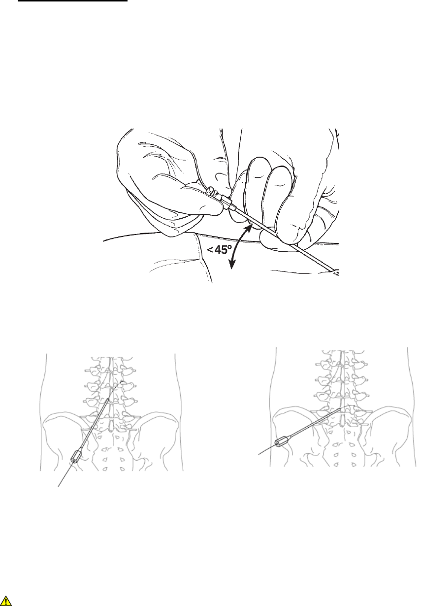
2. AntegradeApproach
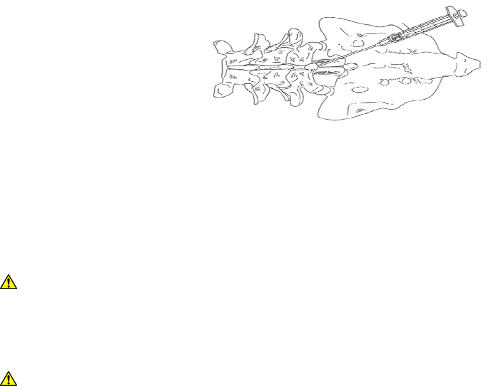
Underfluoroscopicguidance,useacontralateralapproach,withthebeveloftheneedle
facingtowardthetargetlevel,toinserttheDeliveryNeedleintotheepiduralspaceatthe
appropriateangleuntilyouencounterresistancefromtheligamentumflavum.Startoneor
twolevelsbelowthetargetsite.Theneedleangleshouldbenogreaterthan30degreesto
ensuresmoothdeliveryofthedeliverysheathandlead.
SingleLevelDeliveryApproachTwoLevelDeliveryApproach
3. ContralateralApproach
Underfluoroscopicguidance,useacontralateralapproachwiththebeveloftheneedle
facingtowardthetargetleveltoinsertthe14Gdeliveryneedleintotheepiduralspace.
WARNING:Whenusingacontralateralapproach,advancetheneedleslowlyintothe
epiduralspaceandtakecautionasitenters.Theneedlewillbeinsertedatasteeper
SpinalModulation,Inc. PhysicianImplantManual
22
anglethaninanantegradeapproachandthereisagreaterchanceofduralpuncturethat
willleadtoacerebrospinalfluidleak.
4.
Confirmentryintotheepiduralspaceusingstandardmethods,suchasalossofresistance
technique.
5. Oncelossofresistanceisachieved,theclinicianmayverifycompleteinsertionintothe
epiduralspaceusingfluoroscopicguidanceand/orinsertingtheguidewirethroughthe
needle.Ifresistanceisdiscoveredduringguidewireinsertion,eitherpulltheneedleoutand
repeatSteps1‐4usingamoreacuteangleoradvancetheneedlefurtherandreconfirm
placementusingtheguidewire.
WARNING:Usefluoroscopyandextremecarewheninserting,advancing,or
manipulatingtheguidewireorleadintheepiduralspacetominimizetheriskofadural
tear.
WARNING:Duralpuncturecanoccurifneedleorguidewireisadvancedaggressivelyonce
lossofresistanceisachieved.Advancetheneedleand/orguidewireslowly.
6. Removetheguidewire(ifused)afterconfirmationofaccesstotheepiduralspace.
NOTE:TheComplexCurvedStylethasbeenpre‐insertedintotheleadandtheleadhasbeen
loadedintoa22cmSmallCurveSheathtofacilitatedeliverybytheclinician.
7. Beforeinsertionintotheneedle,pushtheleadoutsidethesheathandverifythatthestylet
ispushedfullydistalwithinthelead.
NOTE:Failuretoensurethestyletiscompletelyinsertedmaymakedeliveryofthelead
moredifficult.
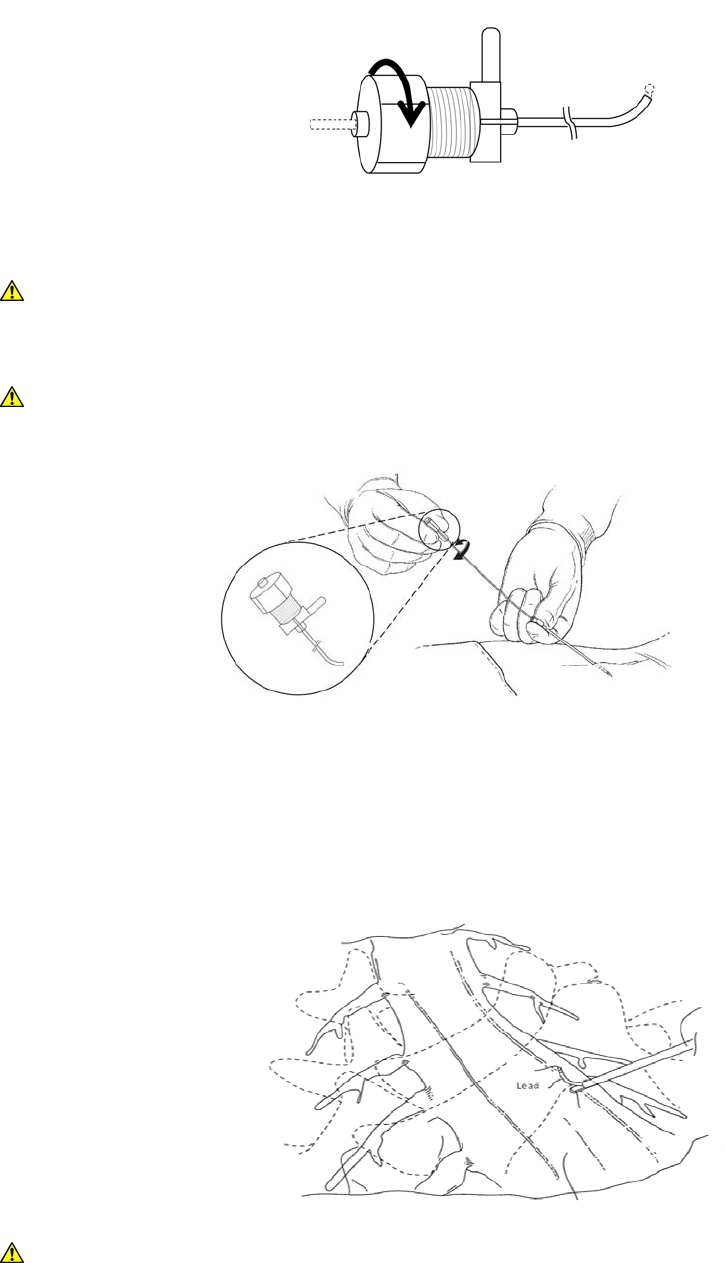
8. Beforeinsertionintotheneedle,pullbackontheleadsothattheball‐tipendoftheleadis
flushagainsttheDeliverySheathandtightendowntheleadstabilizeruntiltheleaddoes
notslidewithinthesheath.
SpinalModulation,Inc. PhysicianImplantManual
23
TighteningtheLeadStabilizer
WARNING:Insertionofasheathwithouttheleadmayresultinduralpuncture.Securing
theleadwiththeleadstabilizerwillmitigatethisrisk.
WARNING:UseofthedeliverysheathisnecessaryforsuccessfulplacementoftheLead.
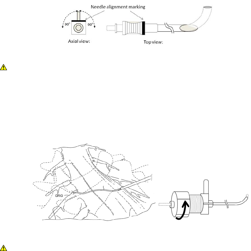
9. Notethatthesteeringwingonthesheathlinesupwiththebendinthesheath.
10. Beforeinsertingthesheathintotheneedle,verifythattheLeadisloaded.TheLeadcannot
bedeliveredthroughthesheathoncethesheathislocatedwithintheepiduralspace.
11. Insertthesheath,lead,andstyletthroughtheneedleandadvancethroughtheepidural
spacetothetargetforaminalopening.
WARNING:Ifthesheathneedstoberetractedfromtheepiduralspace,verifythatthe
steeringwingisnomorethan90degreesmisalignedwiththemarkontheneedle.Failure
SpinalModulation,Inc. PhysicianImplantManual
24
todosomayresultindamagetothesheath.Beforereinsertingsheath,verifythereisno
damagetothesheath.
WARNING:Ifthesheathisnotrespondingtorotation,donotrotatethesteeringwing
outofplanefromthecurveofthesheathmorethan90degrees.Thetipofthesheath
maywhiparoundandcouldcauseharmtothepatient.
12. Withthedistalendofthesheathinoratthetargetforamen,loosentheleadstabilizer,
andadvancetheleadsothatitmovesintotheforamen.Confirmplacementoftheleadon
thedorsalsideoftheforamenusingalateralfluoroscopicview.Verifythattheelectrodes
extendoutofthesheath.Iftheelectrodesremainwithinthesheath,stimulationwillnot
bepossiblebecauseofhighimpedancereadings.
LooseningtheLeadStabilizer
WARNING:Iftheleadisunabletodeployoutofthesheath,injectsterilewaterorsaline
slowlytoreleasetissuethatmayhaveenteredbetweenthesheathandthelead.Donot
useexcessivepressurewheninjectingthroughthesheath.
SpinalModulation,Inc. PhysicianImplantManual
25
LeadAdvancedAlongDorsalAspectofDRG
WARNING:Donotuseexcessiveforcetopushtheleadorsheathintotheneural
foramenasthismayresultinpermanentortransientnervedamage.Thepatientshould
beawakeandconversantduringthispartoftheproceduresotheycanprovidefeedback
tothephysician.
IntraoperativeTesting
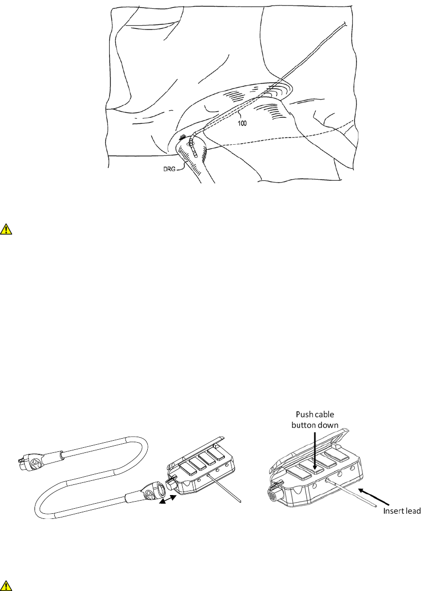
1. Connecttheheadtothecable.Pressandholdthecablebuttondowntoreleasethe
lockingmechanismandslidetheproximalendoftheleadsintothehead.Releasethe
cablebuttontolocktheleadintoplace.Verifythattheleadcomestoastopbefore
releasingthebutton.Thiswillensurethattheelectricalcontactsareintheappropriate
position.
2. PuttheTNSinstandbymodeorturntheamplitudeofeachleadsettozero.
PRECAUTION:Putthetrialstimulatorinstandbymodeorreduceamplitudeofleadsto
zerobeforeplugginginthecable.Failuretodosomayresultindeliveringan
uncomfortablestimulationtothepatient.
3. PasstheproximalendoftheConnectorCableoffthesterilefieldandconnecttotheTNS.
Head

SpinalModulation,Inc. PhysicianImplantManual
26
NOTE:RefertotheTrialNeurostimulatorUserManualandClinicalProgrammerUser
Manualforspecificinstructionsontheoperationofthesedevices.
WARNING:Maintainadequateslackinthecable.Ifthereisnotenoughslackandthe
cableispulled,theleadmaybedislodgedandwillneedtobereplaced.Thiswillextend
theprocedure.
4. UsingtheTNS,testthevariouselectrodeconfigurationsusedtoobtainappropriate
paresthesiaorpainrelief.
5. TurnofftheTrialNeurostimulatoranddisconnecttheleadfromtheconnectorcable.
6. Uptofourleadsmaybeplacedinonepatient.Referto“PlacingtheLead”toposition
subsequentleads.
WARNING:AsdescribedintheClinicalProgrammerUserManual,alwaysturnthe
externalTNSamplitudeto0µAwhenrepositioningalead,changingtheselected
electrodecombination,orattachingtheConnectorCabletotheexternalTNS.When
restartingstimulation,increasetheamplitudeSLOWLYuntilthedesiredparesthesiais
achieved.Failuretodosomayresultinuncomfortablemotoractivationorpainful
stimulation.
RemovingtheDeliverySystemComponents–PercutaneousLeadTrial
1. Beforeremovingthedeliverysystemcomponents,advancetheleadfurtherintothe
epiduralspacetocreateastrainrelief.
2. Slowlyremovethedeliverysheathbyfirstpullingbackthesheathneartheneedle.Always
holdforwardpressureontheLeadwhileretractingthedeliverysheathtopreventlead
migration.
3. Retractthestyletintotheneedlesothatitisretractedbeyondthetipofthesheath.
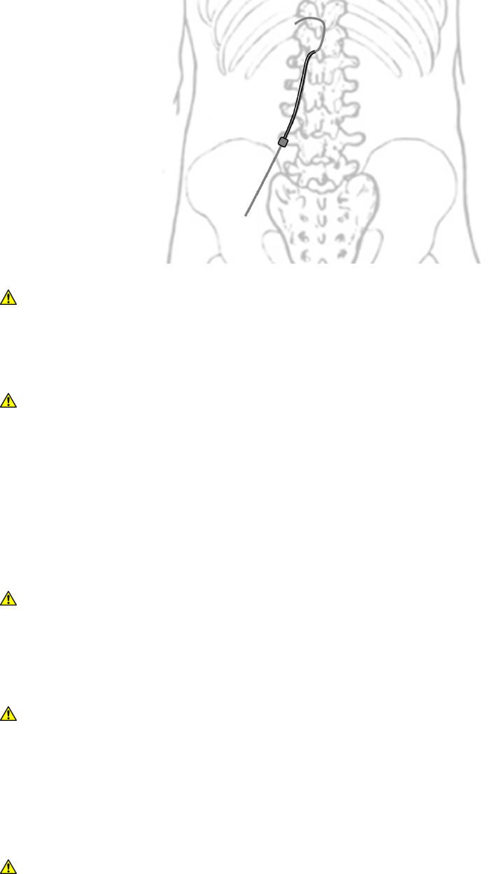
4. Turnthesheathawayfromtheopeningoftheforamenandpushouttheleadsothata
loopiscreatedintheepiduralspace.
SpinalModulation,Inc. PhysicianImplantManual
27
WARNING:Failuretoputaloopintheepiduralspacemayresultinleadmigrationand
mayleadtoaproceduretorevisetheposition.
5. Removethesheathcompletelywhileholdingforwardpressureonthelead.
WARNING:Whenremovingthesheath,verifythatthesteeringwingisnomorethan90
degreesmisalignedwiththemarkontheneedle.Failuretodosomayresultindamage
tothesheath.Beforereinsertingsheath,verifythereisnodamagetothebendofthe
sheath.
6. Removetheneedlefollowingthesameprocedure.Itisrecommendedthatthedesired
paresthesiabere‐testedaftertheremovalofthedeliverysystemcomponentsbutbefore
thecompleteremovalofthestylet.WiththeexternalTNSamplitudesetto0µA,
reconnecttheConnectorCableasdescribedbefore.
WARNING:Ifthesheathhasbeenkinkedduringdelivery,slowlyretractthroughthe
needlewiththecurvefacingthesamedirectionasthebevel.Failuretodosocan
damageorcuttheleadorsheath.Ifresistanceisencountered,pulltheneedleoutofthe
epiduralspaceandthenremovethesheath.
WARNING:Donotuseexcessiveforceiftheleadneedstoberemoved.Excessiveforce
maycauseleadfracture.
7. RecordtheleadpositionwithbothanA/Pandlateralfluoroscopicviewforcomparisonof
thepositionattimeofclosuretoensurethattheleadhasnotmoved.Removethestylet
byholdingforwardpressureontheleadwhileretractingthestylet.
WARNING:Useextremecarewhenremovingtheleadstylet,thedeliverysheath,and
theneedle,toinsurethatthedistaltipoftheleadremainsinthedesiredlocation.
Removingeachiteminslowmovements,whileholdingtheremainingcomponentsin
SpinalModulation,Inc. PhysicianImplantManual
28
place,willassistthisprocess.
LeadAnchoring–PercutaneousLeadTrial
1. AfterplacingaTrialleadinitsfinalposition,itshouldbesecuredusingaleadanchoron
theskin.
2. CarefullyslidetheleadanchorovertheproximalendoftheTrialLeadandadvanceitto
thepuncturesite.Theshortendofthesutureanchormustbefacingtowardstheincision.
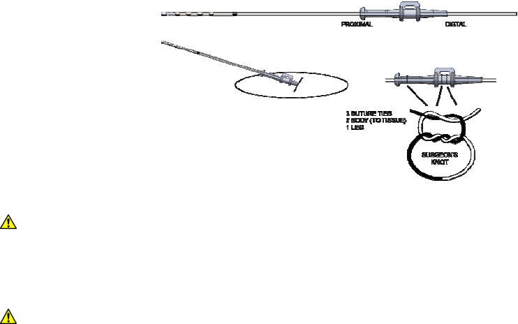
3. ApplysuturesaroundtheanchorandcinchontotheTrialLeadasshownbelow.Applyat
leasttwotiestothemainbodyandonetietotheleg.
WARNING:Donotsuturedirectlyontothelead,asthereisariskofdamagingthelead.
Failuretosecuretheleadtotheskin,orothertissue,mayresultinleadmigrationand/or
motoractivationorpainfulstimulation.
WARNING:Failuretocomplytotheanchoringtechniquemayresultinleadmigration
and/ormotoractivationorpainfulstimulation.
4. Applyanantibacterialagenttothepuncturesite,ifdesired
5. ReconnecttheconnectorcabletotheleadsandcoilanyexcessTrialLeadlengtharound
thedistalendoftheConnectorCable,foldagauzepadaroundtheblock,andapplyalarge
adhesivepatchovertheareacontainingtheTrialLead(s),puncturesiteandConnector
Cable.
6. VerifytheconnectionoftheConnectorCabletotheTrialLeadsandtheexternalTNSprior
todischargeofthepatient.
NeurostimulationTrial–PercutaneousLeadTrial
1. UsingtheClinicalProgrammer,programtheTNSwiththeneurostimulationtrial

SpinalModulation,Inc. PhysicianImplantManual
29
parameters.
NOTE:RefertotheTrialNeurostimulatorUserManualandClinicalProgrammerUserManual
forspecificinstructionsontheprogrammingofthesedevices.
RemovingTrialLead–PercutaneousLeadTrial
WARNING:AlwaysremovetheTrialLeadsbeforeimplantingtheImplantLeads,asthere
isariskofinfectionthatmaycausedeathiftheleadsarenotremoved.Alwayspractice
propersterilepracticeswhenimplantingleadsandimplantableneurostimulator.
ToremovetheTrialLead(s)fromapatient:
1. DisconnecttheConnectorCableconnectionforeachTrialLead.
2. RemoveanysuturesoranchorsecuringeachTrialLeadtothepatient’sskin.
3. SlowlyapplylighttensiontoeachTrialLeadandverifythattheleadisretractingfromthe
patient.
4. PlacetheusedTrialLead(s)intoadesignated“Biohazard”packageclearlylabeledwiththe
patient’sIDnumberandtheremovaldate.
5. SendTrialLead(s)backtoSpinalModulationforevaluationasinstructedbyclinical
personnel.
WARNING:DonotremoveaTrialLeadquickly,asthismayresultinleadbreakageand
unintentionalleadfragmentsbeingleftinthepatient.
WARNING:TakeproperprecautionswhenhandlingremovedTrialLeadcomponents.
TreatallusedTrialLeadsanddeliverycomponentsasa“biohazard”.
WARNING:DonotreuseanydevicefromtheTrialLeadKitorTrialAccessoriesKit.
RemovingtheDeliverySystemComponents–ImplantLeadTrialOnly
TheseinstructionspertainonlyafterplacingImplantLeadduringthetrialprocedure.After
placingaleadinitsfinalposition,usingthetechniquesdescribedabove,itshouldbesecured
usingaleadanchortothesupraspinousligamentorfasciaandthenconnectedtothe
externalizedleadextensions.
WARNING:Donotsuturedirectlyontothelead,asthereisariskofdamagingthelead.
Failuretosecuretheleadmayresultinleadmigrationanduncomfortablemotor
stimulationorpainfulstimulation.
PRECAUTION:Useextremecarewhenusingsharpinstrumentsorelectrocauteryaround
theleadtoavoiddamagingthelead.
1. Leavingtheneedleinplace,preparetheanchorsitebymakinganapproximatelya3‐7cm
SpinalModulation,Inc. PhysicianImplantManual
30
longitudinalincision,centeredontheneedletothedepthofthesupraspinousligament.
2. Establishhemostasisanduseretractorsforgoodvisualization.
3. Slowlyremovethedeliverysheathbyfirstpullingbackthesheathneartheneedle.Always
holdforwardpressureontheLeadwhileretractingthedeliverysheathtoprevent
movement.
4. Retractthestyletintotheneedlesothatitisretractedbeyondthetipofthesheath.
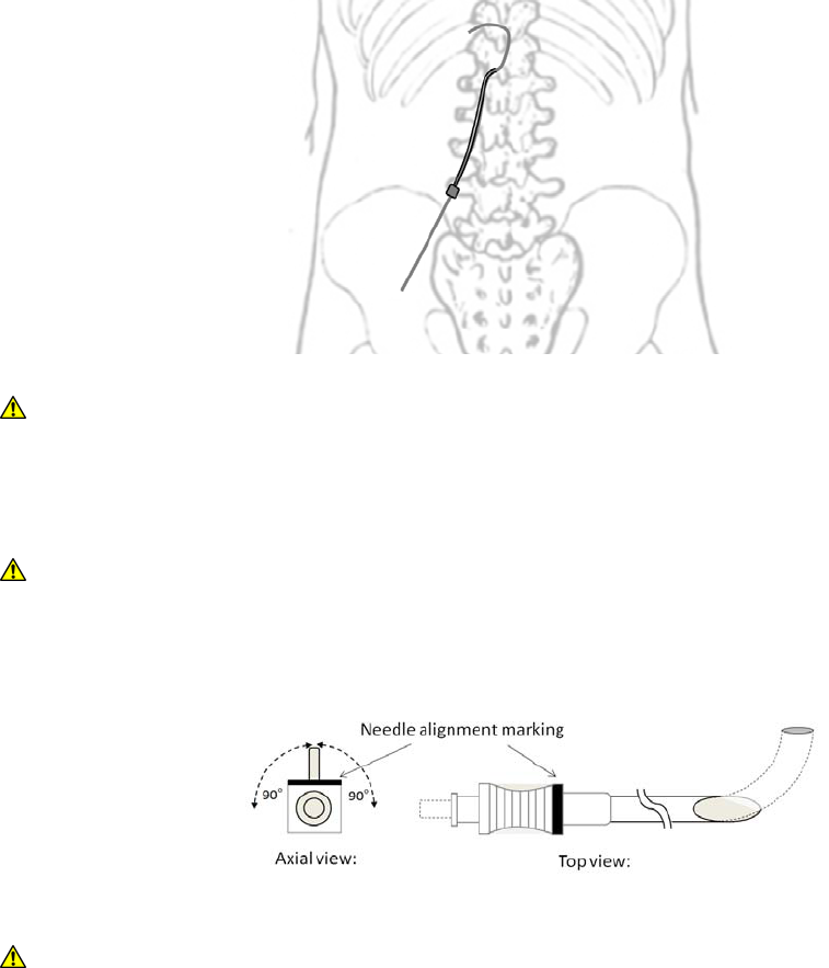
5. Turnthesheathawayfromtheopeningoftheforamenandpushouttheleadsothata
loopiscreatedintheepiduralspace.
WARNING:Failuretoputaloopintheepiduralspacemayresultinleadmigrationand
mayleadtoaproceduretorevisetheposition.
6. Removethesheathcompletelywhileholdingforwardpressureonthelead.
WARNING:Whenremovingthesheath,verifythatthesteeringwingisnomorethan90
degreesmisalignedwiththemarkontheneedle.Failuretodosomayresultindamage
tothesheath.
WARNING:Ifthesheathhasbeenkinkedduringdelivery,slowlyretractthroughthe
needlewiththecurvefacingthesamedirectionasthebevel.Ifresistanceis
encountered,pullouttheneedleandthenproceedtoremovethesheath.Failuretodo
socandamageorcuttheleadorsheath.

SpinalModulation,Inc. PhysicianImplantManual
31
7. Removetheneedlefollowingthesameprocedure.
8. Itisrecommendedthatthedesiredparesthesiabere‐testedaftertheremovalofthe
deliverysystemcomponentsbutbeforethecompleteremovalofthestylet.Withthe
externalTNSamplitudesetto0µA,reconnecttheConnectorCableasdescribedbefore.
WARNING:Donotuseexcessiveforceiftheleadneedstoberemoved.Excessiveforce
maycauseleadfracture.
9. RecordtheleadpositionwithbothanA/Pandlateralfluoroscopicviewforcomparisonof
thepositionattimeofclosuretoensurethattheleadhasnotmoved.Removethestylet
byholdingforwardpressureontheleadwhileretractingthestylet.
WARNING:Useextremecarewhenremovingtheleadstylet,thedeliverysheath,and
theneedle,toensurethatthedistaltipoftheleadremainsinthedesiredlocation.
Removingeachiteminslowmovements,whileholdingtheremainingcomponentsin
place,willassistthisprocess.
LeadAnchoring
Afterplacingaleadinitsfinalposition,itshouldbesecuredusingasofttissueanchorandthen
connectedtoexternalizedextensions.
WARNING:Donotsuturedirectlyontothelead,asthereisariskofdamagingthelead.
Failuretosecuretheleadtotheskin,orothertissue,mayresultinleadmigrationand
uncomfortablemusclestimulation.
PRECAUTION:Useextremecarewhenusingsharpinstrumentsorelectrocauteryaround
theleadtoavoiddamagingthelead.
1. Soaktheanchorinsterilewater(notsaline)tolubricateit.
2. Placetheanchorontheleadandslideitdownascloseaspossibletowherethelead
emergesfromthevertebralcolumn.Becarefulnottomovethelead.
NOTE:Ifimplantingmultipleleads,tagtheleadswithsuture(ligature)sothattheirposition
canbeidentifiedlater.
PRECAUTION:Observethesecautionswhenattachingthesofttissueanchorbecause
damagetotheanchororleadcanoccurandresultinfailureofthesystem:
• Donotusepolypropyleneormonofilamentsuture
• Donotplacesuturesdirectlyonthelead.
• Avoidsharpbendsorkinkingonthelead.
SpinalModulation,Inc. PhysicianImplantManual
32
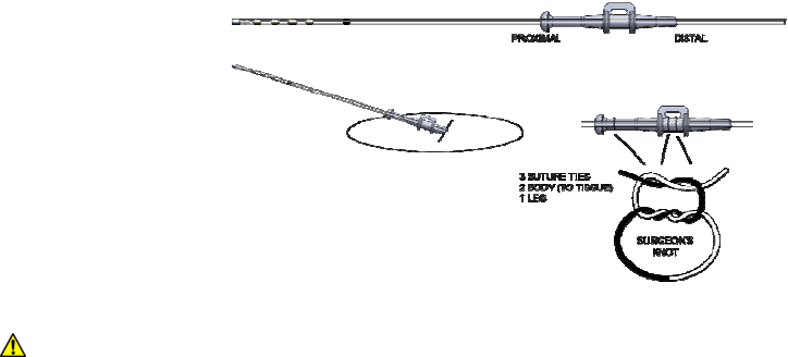
3. Usingthe2‐0silknon‐absorbablesuture,tietwoligaturesaroundthecenteroftheanchor
tosecuretheanchortothelead.Ifneeded,makeminoradjustmentstotheleadposition.
Tieoneligaturearoundtheleganddonottietothesofttissue.Verifythattheshortend
oftheanchorentersintotheligament.
PRECAUTION:Failuretopushtheshortendofthesofttissueanchorintotheligamentor
fasciamayresultinleadmigrationandaproceduretorevisetheleadlocation.
4. Itisrecommendedthattheleadpositionisverifiedunderfluoroscopyanddesired
paresthesiabere‐testedafterfixation.WiththeexternalTNSamplitudesetto0µA,
reconnecttheConnectorCableasdescribedbefore.
PercutaneousExtensionTunneling–ImplantLeadTrialOnly
1. Identifythetunnelingroutebetweentheleadincisionandtheextensionexitsite.
2. Administeranestheticattheexitsiteandalongthetunnelingroute.
3. Assemblethetunnelingtoolpackagedwiththeleadbyslippingthepassingstrawoverthe
tunnelingrod,thenattachingthetunnelingtip.
4. Bendthetunnelingtoolasnecessarytoconformtothepatient’scontouralongthe
tunnelingroute.
5. Makeastabwoundattheexitsite.
6. Beginattheexitsiteandtunnelsubcutaneouslytotheleadincision
7. Guidethetunnelingtoolsubcutaneouslyalongthetunnelingroutebypushingtheskin
overtheadvancingtooltipuntilthetipandapproximately1cmofthepassingstraware
exposedattheleadincision.
8. Withdrawthetunnelingtoolleavingthepassingstrawinplaceinthetunnel.
9. Gentlyinserttheproximalendoftheextensionthroughthepassingstrawtotheexitsite.
SpinalModulation,Inc. PhysicianImplantManual
33
10. Slidethepassingstrawovertheextensionandoutoftheskinexitsite,leavingthe
extensioninplace.
11. Ifnotdonepreviously,usebluntdissectiontoaformasubcutaneouspocketoffthelead
incisionforthelead‐extensionconnection.
12. Wipetheleadandextensionconnectorjunctionwithsterilegauze.Ifnecessary,moisten
thegauzewithsterilewateroranonionicantibioticsolution.
13. Dryallconnections.Fluidintheconnectionmayresultinstimulationattheconnection
site,intermittentstimulation,orlossofstimulation.
14. Holdtheextensionconnectorstraightwhilefirmly,butgently,insertingtheleadintothe
connectoroneortwocontactsatatimeuntileachleadcontactisalignedundereach
extensionconnectorcontact.Duringinsertion,someresistanceistypicalbecausethe
internalsealsprovideelectricalisolation.
15. Verifythatthemarkontheleadalignswiththeendoftheextensionconnector.Thiswill
verifythattheleadisfullyinserted.
16. Usethetorquewrenchsuppliedinthepackagetotightenthesetscrew.Tightenuntila
clickisheard.Usingminimalforce,andwhilesecurelyholdingtheleadtoprevent
dislodgement,pullontheconnectiontoensurethatitissecure.
17. Usingminimalforce,pulltheextensionfromtheskinexitsite,feedingthelead‐extension
connectionintothelead‐extensionconnectionpocket.
18. Inordertoaidinidentificationofeachleadafterthetrialperiod,tieasuturelightlytothe
leadandanotheronetotheleadextension.Usedifferentcolorsutureandnumbersof
suturetoidentifytheleads.Thiswillaidinidentificationduringtheimplantprocedure.
19. Createstrainreliefloopsbycoilingexcessleadproximaltothesofttissueanchorinloops.
Insertthecoiledleadintothepocket,undertheconnection,leavingasmuchslackas
possibleintheleadbetweentheanchorandthelead‐extensionconnection.
20. Closetheincisionanddresstheincisionsite.
21. Attheexitsite,coilanyexcessextensionaroundthedistalendoftheConnectorCable,
foldagauzepadaroundtheblock,andapplyalargeadhesivepatchoverthearea
containingexitpuncture,excessextension,andConnectorCable.
RemovingLeadExtension–ImplantLeadTrialOnly
1. Removethebandageneartheexitpointoftheleadextension.
2. Pulltheleadextensionlightlyoutoftheincisionandcuttheleadextension.
3. Exposethelead‐extensiontoleadconnection.
4. Whilemaintainingleadposition,carefullyremovethelead‐extensionconnectionsfromthe
incision.
5. Disconnecttheleadfromtheextension.
SpinalModulation,Inc. PhysicianImplantManual
34
6. Cuttheextensionnearthelead‐extensionconnector.
7. Discardthelead‐extensionconnector.
8. Preservingsterility,pulltheextensionoutthroughtheskinexitsite.
9. Discardtheextension.
10. Ifmultipleextensionsareimplanted,repeattheremovalstepsfortheotherextensions.
CreatingtheINSPocket–Implant
Oncethelead(s)hasbeenanchored,aNeurostimulatorpocketshouldbecreatedandthelead
tunneledforconnectiontotheINS.
ThefollowingstepsoutlinethesuggestedproceduretocreateanINSpocket:
1. DeterminethesitefortheINS.Thisshouldbedonebeforeimplantingtheleadtoverify
thereisenoughlengthtoreachtheINSpocketandprovidestrainreliefinthepocket,near
theanchor,andintheepiduralspace.
NOTE:TheINSshouldbelocatedinanareathatthepatientcaneasilyreachwiththe
magnetand/orprogrammer:
• Intheupperbuttocksalongtheposterioraxillaryline(avoidingthebeltline)
• Justovertheabdomenbelowthelowestrib
2. Administerlocalanestheticattheneurostimulatorpocketsite.
3. UsebluntdissectiontocreateapocketsothattheINSisparalleltotheskinsurfaceandno
deeperthan2.0cmbelowtheskinsurface.Useelectrocauterytomaintainhemostasis.
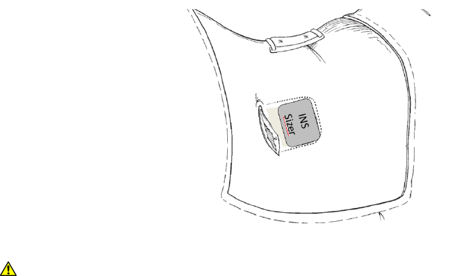
4. (Optional)InserttheINSsizertoensurethepocketislargeenoughtoaccommodatethe
INS,allowingextraroomforastrainreliefloopforeachlead.
PRECAUTION:DonotimplanttheINSdeeperthan2.0cm,astheprogrammerwillnotbe
abletocommunicatewiththeINS.

SpinalModulation,Inc. PhysicianImplantManual
35
PRECAUTION:DonotapplyelectrocauterydirectlytotheINSasthiscandamagetheINS
orcauseinterferencewhilecommunicatingwiththeINS.
LeadorExtensionTunneling
TunneltheleadsfromtheanchorsitetotheINSpocket.Whentunnelingtotheabdomen,the
clinicianhastwooptions:
• TunneltoamidpointandthencontinuetoINSsite.
• Usethe51cmtunnelingtoolandcurvetheconduitaroundthesideofthepatient.
Thefollowingstepsoutlinethesuggestedproceduretotunnelfromtheleadanchorsitetothe
INSpocket:
PRECAUTION:Useextremecaretonotdamagetheleadwiththesharppointofthe
tunnelingtool.
1. Identifythetunnelingroutebetweentheleadincisionandtheneurostimulatorpocket.
2. Administerlocalanestheticalongthetunnelingroute.Additionalsedationmaybe
administeredatthediscretionofthephysician.
3. Bendthetunnelingtoolasnecessarytoconformtothepatient’scontouralongthe
tunnelingroute
4. Withthestrawinplaceonthetunnelingtool,tunnelfromtheINSpockettothelead
anchorsite.
5. Withdrawthetunnelingtoolfromthestraw,leavingthestrawinthesubcutaneous
tunnel.
PRECAUTION:LeadsorExtensionsshouldberoutedadjacenttooneanotherastoprevent
changesinperceivedstimulationfromtheftdetectorsandmetalscreeningdetectors.
6. PasstheendoftheLead(s)orExtension(s)throughthestrawfromtheanchorsitetothe
INSpocketortothemidpointiftunnelingtotheabdomen.Ateachincisionpoint,leave
astrainreliefloopinplaceastominimizethechancesofleadmigration.
7. Removethestrawfromthetunnelbypassingitovertheleads,takingcarenottocause
tractiononthemanddisturbtheleadposition.
ConnectingLeadtoExtension
IfanextensionisusedtoconnecttheLeadtotheINS,refertothesection“Percutaneous
ExtensionTunneling”forinstructionsonhowtoconnecttheExtensiontotheLead.
SpinalModulation,Inc. PhysicianImplantManual
36
ConnectingtheINS
ThefollowingstepsoutlinetheguidelinestoconnectingaLeadorExtensiontotheINS:
PRECAUTION:Donotconnectaleadwithbodyfluidonitscontactsbecausecorrosioncan
occurandcausefailureofthesystem.
PRECAUTION:IfthereisaneedtocommunicatewiththeINSpriortoimplantation,donot
puttheINSonastainlesssteeltable,ascommunicationmaybedifficult.Thismayprolong
theprocedure.
1. Iftheleadcontactscameincontactwithbodyfluidsorsaline,thoroughlycleanwith
steriledeionizedwaterorsterilewaterforirrigationandthendrythemcompletely.
2. Usingcleangloves,carefullyslidetheleadorextensionintotheINSheaderuntilthe
depthmarkeralignswiththeedgeoftheheader.
PRECAUTION:UseonlythetorquewrenchprovidedbySpinalModulationorthedeviceor
leadmaybedamagedandunusable.Tightenuntilaclickisheardortheleadmaymake
intermittentcontactwiththestimulator.
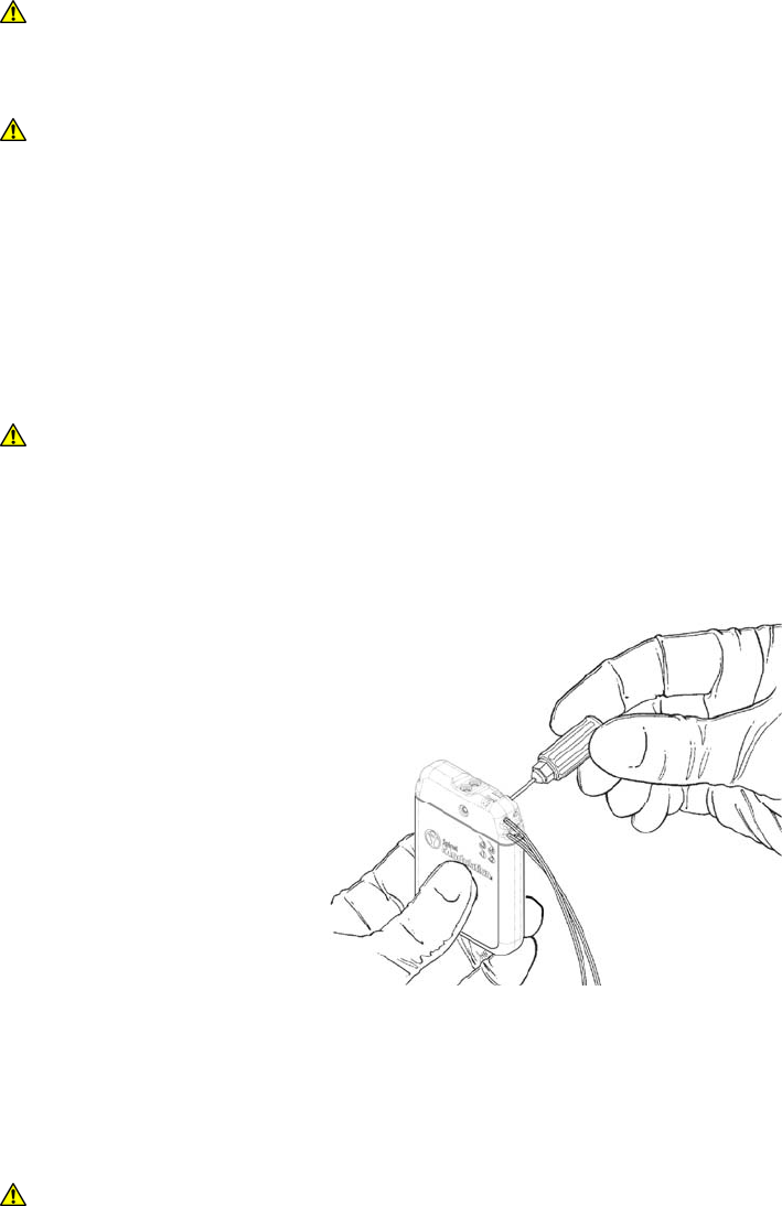
3. Insertthetorquewrenchthroughthesealplugandtightenthesetscrewbyturningit
clockwise,untilthewrenchclicks.
4. Carefullyremovethetorquewrenchandverifythattheseptumoverthesetscrewis
closed.Reseattheflapsifitisnotclosed.
5. Ifimplantinglessthan4leads,inserttheportplugsineachofthevacantheaderports.
Usethetorquewrenchtotightenthesetscrewontheportpluguntilitclicks.
PRECAUTION:InserttheleadslowlyintotheheadertopreventdamagetotheINS.Ifthe
leadneedstoberetracted,retracttheleadslowly.
SpinalModulation,Inc. PhysicianImplantManual
37
ImplantingtheINS
ThefollowingstepsoutlinetheprocedureforimplantingtheINS:
PRECAUTION:DonotimplanttheINSfacedown.Alwaysimplantwiththelabelfacingup.
Failuretodosowillpreventcommunicationwiththeprogrammerand/ormagnet.
PRECAUTION:IfusingmorethanINS,implantthematleast15cmapart.Puttingthemtoo
closetogethermayinterferewiththeprogrammer’sabilitytocommunicatewitheachone
separately.
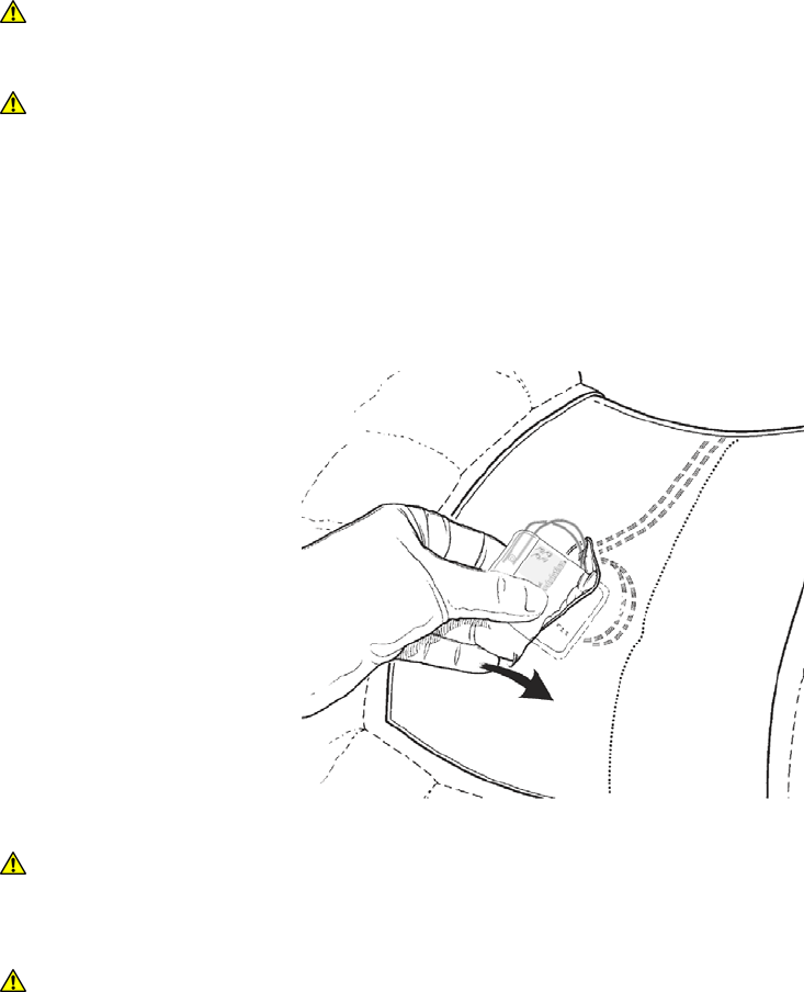
1. PlacetheINSintothepocketatadepthnogreaterthan2cmfromtheskinsurface,with
thelabelfacingtheskinsurface.
2. CarefullycoilexcessleadbehindtheINSoraroundtheINSinloopstoprovidestrain
relieffortheleadandINSconnection.
PRECAUTION:CoilingtheleadonthetopsurfaceoftheINS(closesttotheskin)will
interferewiththeabilityoftheprogrammertocommunicatewiththedevice.
PRECAUTION:DonotbringthesutureneedleincontactwiththeINS,orleadduring
sewingtheINSintothepocketorclosingthepocket.Thecomponentsmaybedamageif
thisoccurs.
3. TostabilizetheINSwithinthepocket,passasuturethroughthetwosutureholesinthe
INSandsecureittoconnectivetissue.
4. Checktheentiresystembyfluoroscopypriortoclosingtoensureproperpositioningof
theleads.Verifythattheleadshavenosharpbendsorkinks.
5. PlacethemagnetintoasterilebagandwaveovertheINS.
SpinalModulation,Inc. PhysicianImplantManual
38
6. Slowlyawakenthepatientandtestforstimulationperceptionandtherebyverifyingthe
systemisoperational.
NOTE:TheINSoutputmaynotbeidenticaltothetrialneurostimulatoroutput.Alwaysstart
stimulatingfromasettinglowerthanthatusedtostimulatewiththetrialneurostimulator.
7. EnsurethatthattheINSisawayfromthepocketincisionsutureline,closethepocket
incision,andapplyappropriatedressings.
8. FilloutthepatientregistrationinformationformandreturnittoSpinalModulation.
CheckingSystemIntegrity
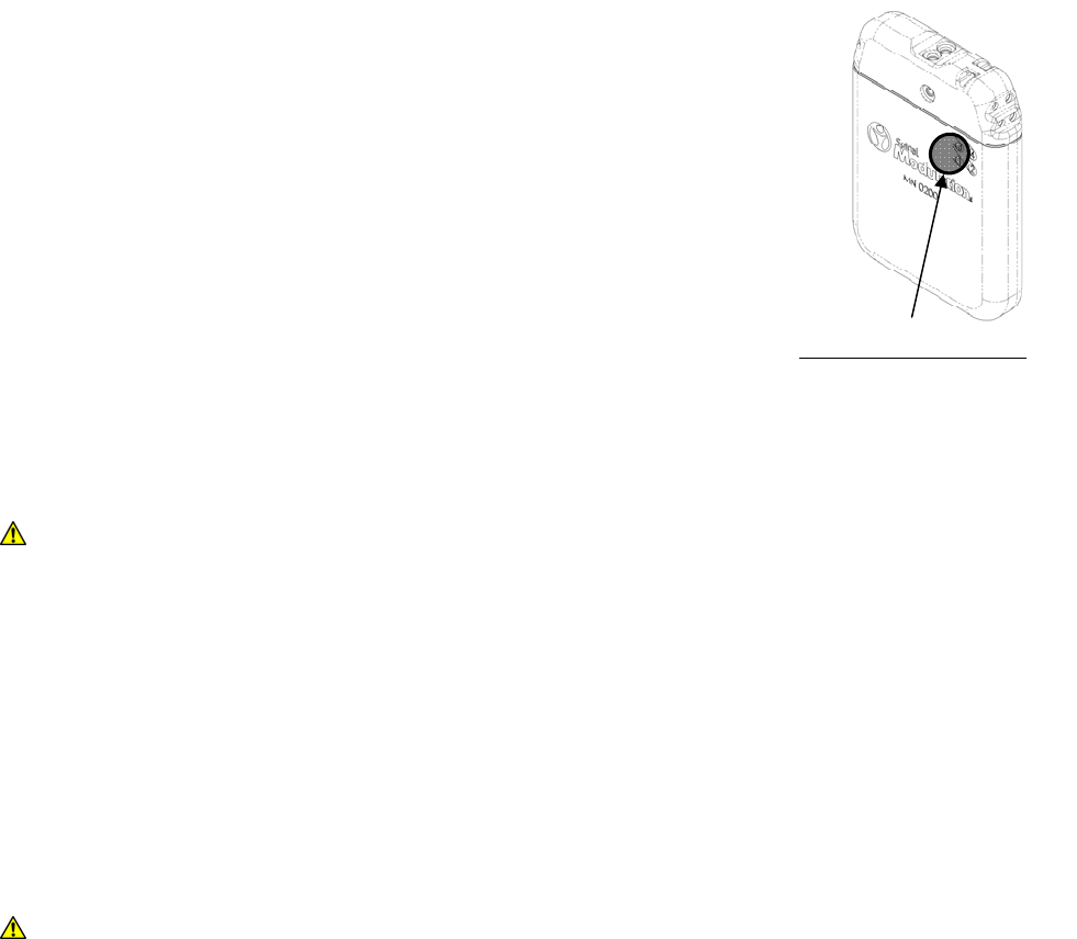
1. Placethemagnetinasterilepouchandwaveitoverthedeviceto
startprogrammercommunication.
2. Usingtheclinicalprogrammerinthenon‐sterilefield,program
thebasicstimulationparameters,checkthebatterystatus,and
checktheelectrodeimpedancestoensurethereisnoshortor
opencircuit.
3. Oncethesystem’sfunctionisverified,turntheneurostimulatoroff.
CompletingtheProcedure
1. Followstandardprocedureforwoundclosureandbandaging.
ReplacinganINS
ThefollowingstepsoutlinethesuggestedproceduretoreplaceanINS:
1. TurnofftheINSandverifythatithasbeenturnedoff.
PRECAUTION:Exercisecarewhenusingsharpinstrumentsorelectrocauteryaroundleads
ortheymightbedamaged.
2. OpentheINSimplantsitepernormalsurgicalprocedures.
3. RemovethesuturefromtheINSheader,withoutdamagingthelead,andcarefully
removetheINSfromthepocket.
4. CleantheINSheaderandtheleadwithsterilewaterandthenwipewithasurgical
sponge.
5. InsertthetorquewrenchthroughtheseptumoftheINSheaderandloosenthesetscrew
byturningitcounterclockwise.
PRECAUTION:Whenperformingthefollowingsteps,donotbendtheleadsharplyasthis
maycauseleadbreakage.
MagnetActivationTarget
Magnetmustbewithin3.5
cmofINSsurfacefor
activationof
communication.

SpinalModulation,Inc. PhysicianImplantManual
39
6. GentlyremovetheleadfromtheINSheader;thencleananddryallconnectionsonthe
lead,ensuringtheyarefreefromfluidandtissue.
PRECAUTION:Ifresistanceismetwhileremovingleadsfromtheepiduralspace,donot
useexcessiveforcetoextract.Alwaysperformremovalwiththepatientconsciousand
abletogivefeedback.
WARNING:Donotremovealeadquickly,asthismayresultinleadbreakageand
unintentionalleadfragmentsbeingleftinthepatient.
WARNING:Takeproperprecautionswhenhandlingremovedleadcomponents.Treatall
usedleadsanddeliverycomponentsasa“biohazard”.
7. Ifyouneedtoreplacealead,performthefollowingactions:
a. Makeanincisionabovethelocationofthesutureanchor.
b. Carefullycutthesuturesfromthesutureanchor.
c. Slidetheleadoutoftheepiduralspaceslowly.
8. TocompletetheINSreplacementprocedure,see“ConnectingtheLeadtotheINS”.
9. Tocompleteleadplacement,see“PlacingaLead”.
DisposingofanExplantedDevice
AllexplantedINSsshouldbereturnedtoSpinalModulationforproperdisposal.Todisposeof
anexplanteddevice,followthesesteps:
WARNING:Donotcrush,puncture,orburntheINSbecauseitmayexplodeorcatchon
fire.
1. Decontaminatetheexplanteddevice.
2. Placeitinacontainerwithabiohazardlabel.
3. Includeacompleted“ReturnedProductForm.”(OneispackagedwitheachnewINS)
4. Returntheexplanteddeviceto:
SpinalModulation
1135O’BrienDrive
MenloPark,CA94025
U.S.A.

SpinalModulation,Inc. PhysicianImplantManual
40
AppendixA:TrialLeadKit/ImplantLeadKit
HowSupplied
ThecomponentsoftheSpinalModulationTrialLeadKitandImplantLeadKitareprovided
sterileinadoublepouchassemblyandareintendedforsingleuseonly.Donotresterilizeor
reuseanydevicesfromtheLeadKits,foranyreason,becauseofriskofinfectiontothesubject
andmalfunctionofthedevices.
PRECAUTION:DonotresterilizetheLeadKitsoranyothersterilecomponentsasitwill
createariskofinfectionormalfunctionofthedevice.
StorageTemperature‐StoretheTrialLeadKitandLeadAccessoriesKitbetween14°F(‐10°C)
and122°F(50°C).Temperaturesoutsidethisrangemaydamagethecomponents.Ifa
temperaturedeviationhasoccurred,donotusetheproduct.
Sterilization‐TheTrialLeadKit,ConnectorCable,andallLeadKitAccessorieshavebeen
sterilizedusingethyleneoxide(EO)gas.
PackageContents
(1)Trial/ImplantLead50cm/90cm
(1)22cmSmallCurveDeliverySheath
(1)22cmBigCurveDeliverySheath
(1)Guidewire
(1)ComplexCurveStylet
(1)4.5”14GaugeNeedle
(2)SoftTissueAnchors
(1)PhysicianImplantManual

SpinalModulation,Inc. PhysicianImplantManual
41
DeviceSpecification
TheLeadhasfourelectrodesonthedistalendandtheproximalendfitsintoafourconductor
connectorontheConnectorCableorintotheINSports.TheComplexCurvedStylethasbeen
insertedintotheproximalendoftheleadandtheleadhasbeenpre‐loadedintoa22cmSmall
CurveDeliverySheathforuserconvenience.AnillustrationoftheTrialLeadisgiveninFigure1.
Figure1:Leadshowingfourproximalelectricalconnectorsandfourradiopaqueelectrodes
TheapproximatemeasurementsforaTrialLeadarepresentedbelow:
ProximalElectricalConnector..................Quadrapolar,in‐line
CentertoCenterConnectorSpacing ........3.3mm(0.130”)
Diameter ..................................................1.0mm(0.040”)
Length ......................................................50cm(20”)or90cm(35”)
NumberofElectrodes……………………........4
ElectrodeShape…………………………….........Cylindrical
ElectrodeLength ......................................1.25mm(0.050”)
EdgetoEdgeSpacing ...............................5mm(0.200”)
CentertoCenterSpacing.........................6.25mm(0.250”)
ArrayLength………………………………….........20mm(0.790”)
BallTipDiameter......................................1.5mm(0.060”)
StyletWireDiameter………………...............0.25mm(0.010”)
DCLeadImpedance(50cm/90cm/Extension)….<20Ω/<35Ω/<60Ω
SpinalModulation,Inc. PhysicianImplantManual
42
AppendixB:TrialNeurostimulator
DeviceDescription
SeetheTrialNeurostimulatorManualforthefulldescriptionofthedevice.TheexternalTrial
Neurostimulator(TNS)providesenergyandcontrolselectricalsignalsdeliveredtotheLeads.
TheTNSdeviceisintendedtobeconnectedtotheLeadsandwornbythesubjectforupto30
daysduringthestudyperiod.ThedeviceisintendedtobeconnectedtotheSpinalModulation
ConnectorCable.Itisnotcompatiblewithothercablesfromothermanufacturers.The
externalTNSdevicehasabeltclipthatcanbeusedorthesubjectmaychoosetouseaflexible,
elasticbandagetosecuretheirTNSdeviceduringthetrialperiod.Thepatientshouldbe
advisednottoallowtheTNStomakedirectcontactwithskin.
PackageContents
(1)TrialNeurostimulator
(1)TNSManual
DeviceSpecifications
SpecificationsRangeStepSizeDefaultValue
PulseAmplitude‐PA(µA)
(Dependingonmeasuredimpedance)
0–6000µA25µA:0‐2000µA
50µA:2000‐6000µA
0µA
MaximumPulseAmplitude‐Max(µA)
ProgrammablebyPatient
SameasPASameasPA0µA
PulseWidth–PW(µs)40–720µs10µs40µs
PulseFrequency‐PF(Hz)4–100Hz2Hz60Hz

SpinalModulation,Inc. PhysicianImplantManual
43
Handling
StorageConditions:‐10°C‐50°C
HumidityRange:10–93%
CleaningInstructionsforHealthcareProfessional:FordisinfectingtheTNSsurfacesaftergross
filthandheavysoilloadshavebeenremoved,sprayCavicideorequivalentontoapapertowel,
andthenwipethesurfaceoftheTNSwiththewetpapertowel.Allowthesurfacetoremain
dampfor2minutes.Drythesurfaceusingadrypapertowel.DonotimmersetheTNSin
liquid.AdvisethepatientnottocleantheTNSwithexcessiveliquid.Adampclothmaybeused
towipetheTNS,ifnecessary.
WARNING:AlwaysweartheTNSontheoutsideofclothingasthematerialmaycause
skinirritation.
SpinalModulation,Inc. PhysicianImplantManual
44
AppendixC:ImplantableNeurostimulator
HowSupplied
TheAxium™ImplantableNeurostimulatorisprovidedsterileinadoubletrayassemblyandis
intendedforsingleuseonly.Donotresterilizeorreuse,foranyreason,becauseofriskof
infectiontothepatientandmalfunctionofthedevices.
PRECAUTION:DonotresterilizetheINSasitwillcreateariskofinfectionormalfunction
ofthedevice.
DeviceDescription
TheImplantableNeurostimulatorisafourchannelneurostimulatorthatisonlycompatiblewith
SpinalModulationImplantLeadsandLeadExtensions.Ithasfourportstoallowforstimulation
ofuptofourleadssimultaneously.Ithasanantennaintheheaderthatallowswireless
communicationwiththedeviceusingtheSpinalModulationClinicalProgrammerorPatient
Programmer.
PackageContents
(1)ImplantableNeurostimulator
(3)LeadPortPlugs
(1)TorqueWrench
(1)SterileMagnetSleeve
(1)MedicalAlertCard
(1)ReferencetoImplantManual
DeviceSpecifications
OutputoftheINSisequivalenttotheoutputoftheTNS.Thedeviceisprogrammedincurrent,
impedanceismeasuredbythedevice,andtheappropriateoutputvoltagematchesthe
impedanceandcurrentprogrammed.
SpecificationsRangeStepSizeDefaultValue
PulseAmplitude‐PA(µA)
(Dependingonmeasuredimpedance)
0–6000µA25µA:0‐2000µA
50µA:2000‐6000µA
0µA
MaximumPulseAmplitude‐Max(µA)
ProgrammablebyPatient
SameasPASameasPA0µA
PulseWidth–PW(µs)40–720µs10µs40µs
PulseFrequency‐PF(Hz)4–100Hz2Hz60Hz

SpinalModulation,Inc. PhysicianImplantManual
45
TherapyAccuracy.....................................10%overtherangeof300to6000µA
ImpedanceMeasurementAccuracy ........5%overtherangeof400to2000Ohms
Height.......................................................6.52cm(2.57in)
Width .......................................................4.77cm(1.88in)
Thickness..................................................1.10cm(0.43in)
Volume.....................................................31cm3(1.89in3)
MaximumConnectorStrength ................10N
NumberofChannels ................................4
PowerSource ...........................................CFx,lithium‐carbonmonofluoride
StorageTemperature...............................‐10°C(14°F)to50°C(122°F)
StorageHumidity .....................................10%to90%
Handling
StorageConditions:‐10°C‐50°C
HumidityRange:10–90%
Handling:Beforeimplantation,onlywipewithsterilewateranddonotuseanycleaning
agents.
PRECAUTION:Beforeimplantation,donotusechemicalsoranycleaningagentstowipe
theINS.Thismaycauseirritationorinflammationattheimplantsite.
DeviceLongevity
Forinformationregardingdevicelongevity,contactSpinalModulation.
SpinalModulation,Inc. PhysicianImplantManual
46
TheAxium™NeurostimulatorSystemcomplieswiththefollowingInternationalStandards:
• IEC60601‐1:2005
• IEC60601‐1‐11:2010
• IEC60601‐1‐2:2007
• ISO14708‐1:2000
• ISO14708‐3:2008
CompanyandAuthorizedRepresentativeContactInformation
SpinalModulation,Inc.
1135O’BrienDrive
MenloPark,CA94025
U.S.A.
Telephone:(650)543‐6800(24‐hoursupportline)
Fax:(650)327‐2336
Email:clinicalsupport@spinalmodulation.com
HealthlinkEuropeB.V.
DeTweeling20‐22
‘sHertogenbosch5215MC
TheNetherlands
Telephone:+31135479300
Fax:+31135479301
AuthorizationtoaffixtheCEmarkgrantedin2011