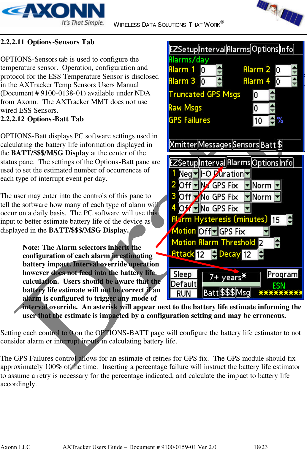
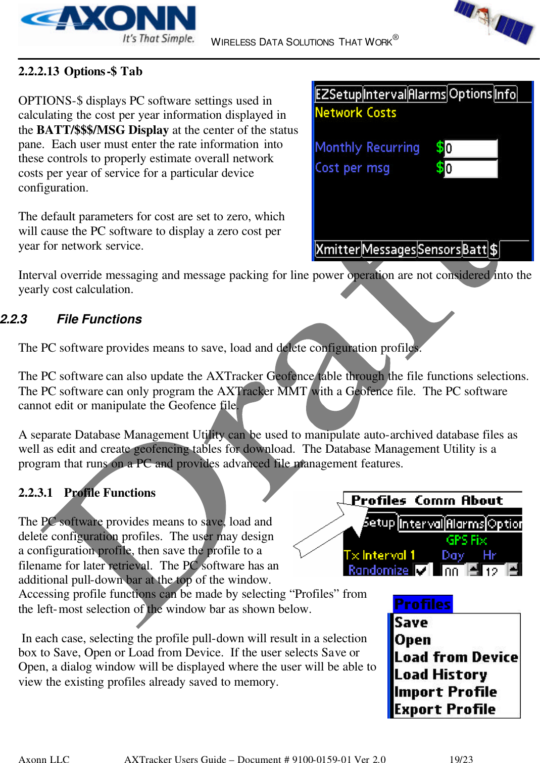
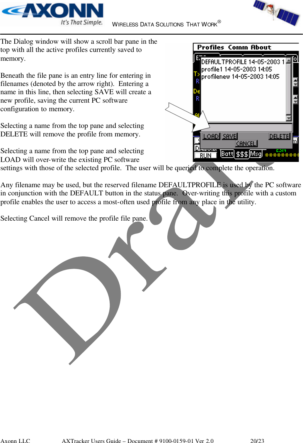
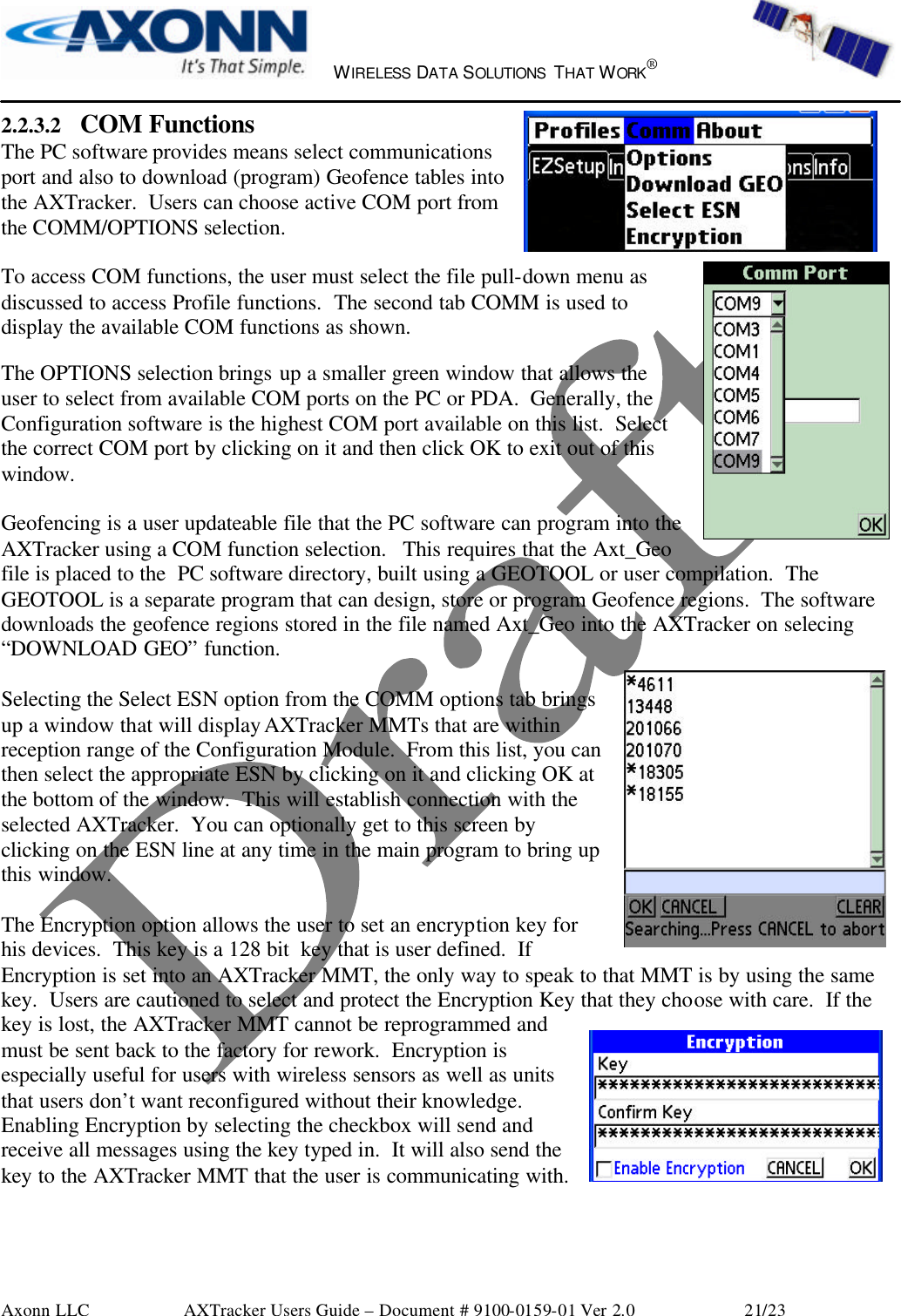
Spot CM1 MMT Configuration Tool User Manual 07 0057 Users Manual

Spot LLC MMT Configuration Tool 07 0057 Users Manual

Users Manual

    WIRELESS DATA SOLUTIONS THAT WORK®   Axonn LLC        AXTracker Users Guide – Document # 9100-0159-01 Ver 2.0                 1/23 Configuration Module Users Manual    Part Number: 9100-0159-01  Revision 2.0    Date: March 26, 2007                ®         Prepared by: Axonn LLC 19349 N 12th  Street Covington, LA 70433 PH:  (985) 893-1048
    WIRELESS DATA SOLUTIONS THAT WORK®   Axonn LLC        AXTracker Users Guide – Document # 9100-0159-01 Ver 2.0                 2/23  INDEX CONFIGURATION MODULE USERS MANUAL..........................................................................................................................1 1 CONFIGURATION TOOL HARDWARE...............................................................................................................................3 1.1 USB CONNECTION...................................................................................................................................................................3 2 TRACKER SETUP SOFTWARE...............................................................................................................................................3 2.1 PC SOFTWARE CONNECTION..................................................................................................................................................3 2.2 PC SOFTWARE LAYOUT...........................................................................................................................................................4 2.2.1 Status Pane....................................................................................................................... 4 2.2.1.1  SLEEP Button............................................................................................................... 4 2.2.1.2  PROGRAM Button....................................................................................................... 4 2.2.1.3  RUN Button.................................................................................................................. 4 2.2.1.4  DEFAULT Button........................................................................................................ 5 2.2.1.5  ESN Display ................................................................................................................. 5 2.2.1.6  BATT/$$$/MSG Display.............................................................................................. 5 2.2.2 User Data Entry Pane ...................................................................................................... 6 2.2.2.1  EZSetup Tab ................................................................................................................. 6 2.2.2.2  Interval Tab................................................................................................................... 9 2.2.2.3  Interval-Intervals Tab ................................................................................................... 9 2.2.2.4  Interval-Override Tab ................................................................................................. 10 2.2.2.5  Interval-Stats Tab........................................................................................................ 11 2.2.2.6  Interval-Advanced Tab ............................................................................................... 11 2.2.2.7  Alarms Tab ................................................................................................................. 12 2.2.2.8  Options Tab ................................................................................................................ 15 2.2.2.9  Options-Xmitter Tab................................................................................................... 15 2.2.2.10  Options-Messages Tab............................................................................................ 17 2.2.2.11  Options-Sensors Tab............................................................................................... 18 2.2.2.12  Options-Batt Tab .................................................................................................... 18 2.2.2.13  Options-$ Tab ......................................................................................................... 19 2.2.3 File Functions................................................................................................................. 19 2.2.3.1  Profile Functions......................................................................................................... 19 2.2.3.2  COM Functions .......................................................................................................... 21 3 REGULATORY APPROVALS ................................................................................................................................................22
    WIRELESS DATA SOLUTIONS THAT WORK®   Axonn LLC        AXTracker Users Guide – Document # 9100-0159-01 Ver 2.0                 3/23  1 Configuration Tool Hardware The MMT Configuration Tool hardware is a self-contained device that allows for wireless communication with the AXTracker MMT.  This is accomplished by a USB serial interface from a PC into the Tool.  From there, an Axonn 2.4 GHz Stamp radio relays information between the Tool and an MMT.  This allows for non-contact programming and configuration of the MMT as well as maintaining the waterproof nature of the MMT product.  The Configuration Tool is powered by the USB cable when connected to a PC.  The center Green LED blinks when there is communication using the 2.4 GHz Stamp radio to and from the MMT.   1.1    USB Connection The Configuration Tool has a USB port on the end of the enclosure.  A standard USB 1.0 (or higher) version cable can be connected between the Tool and a PC running Tracker Setup.  When connected, the Configuration Tool should show up as a new serial port on the computer.  To verify installation, the user can go to the Device Manager under Ports and should see an FTDI brand USB to Serial Interface COM x with x being the number of the serial port.  If there are errors, please contact Axonn Customer Service for support.  2 Tracker Setup Software The AXTracker MMT comes factory configured for use.  The factory configuration may be changed using a Personal Computer (PC) and the Configuration Tool.  This document describes the PC software feature set and its use in configuring the AXTracker MMT.    Some of the features discussed below are not supported in older versions of the product.  The setup software will auto-detect first-generation product and disable features incompatible making the setup software backward compatible with first generation product.  The AXTracker MMT uses a wireless interface for serial communications.  Older AXTracker devices rely on a wired serial connection.  Users may require a different cable interface depending on the AXTracker versions being programmed.  2.1   PC Software Connection The PC Software must be connected to the AXTracker MMT using the Configuration Tool. The Configuration Tool contains a USB port to connect to the PC.  It also has an Axonn 2.4 GHz Stamp radio for wireless connection to the AXTracker MMT.    The PC Software may be used without the Configuration Tool to prepare configurations, but must be connected using the Configuration Tool to make changes to AXTracker MMT internal configuration.
    WIRELESS DATA SOLUTIONS THAT WORK®   Axonn LLC        AXTracker Users Guide – Document # 9100-0159-01 Ver 2.0                 4/23 2.2 PC Software Layout The PC Software layout has a tab-based context-switched user data entry pane on the top 2/3 of the screen and a static status pane on the bottom 1/3 of the screen.  The top, context-switched user data entry pane displays configuration settings.  The bottom, status pane contains execution controls and status including battery life and cost estimates. 2.2.1 Status Pane  The lower 1/3 of the PC Software contains status information and execution buttons for configuring the AXTracker.  2.2.1.1   SLEEP Button  The SLEEP button in the status pane is used to force the connected AXTracker into inventory sleep mode.  The AXTracker will suspend operations and begin deep-sleep function awaiting wakeup at a later time.   The SLEEP button is used to configure a device to a custom configuration, and then return it to a mode where it can be inventoried for later installation.   The user is queried to confirm SLEEP function (inventory mode) before executing the function.  2.2.1.2 PROGRAM Button  The PROGRAM button in the status pane is used to send the data in the PC Software to the connected AXTracker.  The AXTracker will be updated with the data from the PC Software.    The user is queried to confirm device program before execution of the function.  Following PROGRAM, the AXTracker will begin a 1 minute timeout following PROGRAM and auto-enter into RUN mode.  2.2.1.3  RUN Button  The RUN button in the status pane is used to initiate the AXTracker into RUN mode.  The AXTracker will begin operation using the configuration in the device.    NOTE: THE CONFIGURATION IN THE PROGRAM MAY NOT MATCH THE CONFIGURATION IN THE DEVICE.  THE USER MUST PRESS “PROGRAM” IN ORDER TO TRANSFER PROGRAM’S CONFIGURATION TO THE AXTRACKER.
    WIRELESS DATA SOLUTIONS THAT WORK®   Axonn LLC        AXTracker Users Guide – Document # 9100-0159-01 Ver 2.0                 5/23 RUN INSTRUCTS THE AXTRACKER TO BEGIN USING ITS EXISTING CONFIGURATION PROFILE.  The RUN button may be used to begin service life of a device using the pre-programmed configuration.  It may also be used to begin service life following PC software programming.  RUN initiates a “SETUP MESSAGE” followed by begin of Delay-To-Start if programmed.    2.2.1.4   DEFAULT Button  The DEFAULT button in the status pane is used set all the configurable parameters to the special configuration profile allocated to “DEFAULTPROFILE”.  DEFAULT erases the current configuration settings in the program. The user will be prompted to accept the default settings.   DEFAULT allows for quick configuration of a custom profile.  Users may connect the AXTracker to the PC Software, select DEFAULT, PROGRAM, RUN to quickly load a configuration, program the AXTracker and enter it into RUN mode.  Users must save a profile to DEFAULTPROFILE filename to use DEFAULT for quick retrieval of custom default configuration.  See section 4.1.5 for file functions.  2.2.1.5   ESN Display  The Electronic Serial Number (ESN) of the connected AXTracker is displayed in the lower right corner of the status pane.  Each AXTracker has a unique ESN that will be automatically queried and displayed on the PC software.  The program will query an attached AXTracker for the ESN upon device program or when the user selects the ESN with the cursor.  The ESN will show asterisks in the ESN display (*******) for un-queried or unattached devices.  Selecting the ESN display with the stylus or cursor will initiate a manual seek.  Additional data queried from the device is also posted to the INFO pane (top right-most tab of the software).  Software version, device mode and statistics data is posted to this pane.  2.2.1.6   BATT/$$$/MSG Display  At the center of the status pane is a three-tab display, which shows an estimate for battery life, cost per year and messages per year.  The displayed parameters calculate conservative numbers assuming minimums of the configured randomization intervals.  An asterisk will appear behind the estimate when a setting configures the device for operation which is not considered in the battery life estimates, typically interval-override, or motion alarm.
    WIRELESS DATA SOLUTIONS THAT WORK®   Axonn LLC        AXTracker Users Guide – Document # 9100-0159-01 Ver 2.0                 6/23 BATT: Selecting the BATT tab will display the estimated battery life of a device configured with the settings currently displayed in the PC software.  Battery life estimates assume predominate visibility to the sky (predominate GPS acquire on first attempt) and moderate temperature profile. The Battery life display estimates the impact of configuration to service life of the battery.  $$$: Selecting the $$$ tab will display the estimated operational cost per year for a device configured with the settings currently displayed in the PC software.  Cost estimates are based on configuration parameters set in the OPTIONS tab of the context-sensitive users area (top of screen).  MSG: Selecting the MSG tab will display the estimated number of messages per year for a device configured with the settings currently displayed.  Messages displayed are the calculated number of supervisory interval position messages plus alarm or serial sensor generated messages as estimated from the user entry fields in the Options-Batt pane.  NOTE:  Battery usage estimates are based on the parameters of the software and do not include the impact to alarm or interval-override functions.  Users should be aware that the estimates will not be accurate if the unit is configured and encounters significant unscheduled event activity.  2.2.2   User Data Entry Pane  The upper 2/3 of the software contains a context-switched user entry area for displaying and inputting configuration data.   The information is organized in pages with page manipulation provided through tabs along the top of the pane.  Selecting a tab will change the context of the upper pane.  The tabs are named to group similar functions on the same page.  Five primary tabs are provided with the following basic function:  EZSetup: Enables quick and easy setup for                   simple configurations. Interval:  Used to display and configure                   interval position report timing. Alarms:    Used to display and configure the                    alarm capabilities of the device Options:   Used to set advanced configurations of                   the AXTracker and PC software Info:          Displays PC software l and                    AXTracker (if connected) information   The following sections describe the use of each tab and sub-functions of the page.  2.2.2.1 EZSetup Tab  The EZSetup Tab is the default page for the PC software.  This page displays and allows configuration for the most basic of AXTracker functions.  From this page, the device may be setup to perform one-
    WIRELESS DATA SOLUTIONS THAT WORK®   Axonn LLC        AXTracker Users Guide – Document # 9100-0159-01 Ver 2.0                 7/23 level interval functions, configure the delay-to-start and configure one of the four available alarm inputs to the AXTracker.  TX Interval 1:  The AXTracker can accept up to 12 interval delays for interval position reporting.  The AXTracker sequences through the table repeatedly to time GPS fix functions.  The TX Interval 1 control on the EZSetup page shows the settings of the first of twelve timer values.  Additional values may exist and are accessible on the “Interval” tab page.  For simple, one level timer values, the first interval is all that is necessary to configure a device for use.  For example, setting the AXTracker up for daily reads can be accomplished by setting the DAY field to 1.  Delay to Start:  The AXTracker will execute a one-time delay at the start of service life following activation.  This allows for units to be configured and staggered in actual start time.  Staggering unit start and interval reporting can greatly increase message success rate.   The Delay-to-Start parameter is passed to the AXTracker upon PROGRAM function.  The AXTracker begins countdown of the Delay-to-Start upon receipt of RUN or upon timeout following Program (auto-RUN).   On RUN, the AXTracker will send a SETUP message and begin executing the Delay-to-Start interval timer.  At the end of the Delay-to-Start interval the AXTracker will issue its first location message IF the Delay-to-Start is at least 30 minutes.  The first interval is then started as the device begins executing the standard interval function.  ALARM 1:  One of the four available alarm inputs to the AXTracker may be setup from the EZSetup tab page.  Alarm 1 is configurable from the EZSetup page or the ALARMS page. Changing to the alarm 1 setting is also reflected on the ALARMS tab page.  Each alarm may be configured independent of the others.  Each alarm may be configured as:  OFF:   Alarm is disabled.  Inputs on pins are ignored.  NEG:  Alarm is enabled to negative edge signals (pin short to GND) POS:   Alarm is enabled to positive edge signals (release from GND) ANY:  Alarm is enabled to either edge (short-to or release-from GND)
    WIRELESS DATA SOLUTIONS THAT WORK®   Axonn LLC        AXTracker Users Guide – Document # 9100-0159-01 Ver 2.0                 8/23 Additionally, if enabled, each alarm may be configured to perform one of 4 functions.  No GPS Fix:  Alarm generates a message with null (0’s) GPS location data. GPS Fix:   Alarm generates a message with GPS location data. I-O Duration:AXTracker enters Interval-Override mode for programmed duration. I-O Alarm: AXTracker enters Interval-Override mode for duration of alarm active.  The alarm functions are only executed on alarm if the alarm is enabled.  With “NO GPS FIX” enabled, the unit will send an AXTracker message immediately upon alarm with null (zero) LAT/LOG data.  Since it may take up to several minutes to acquire a GPS fix, this mode provides timely notification of an event and also preserves a significant amount of battery.  Up to 80% of the usable battery life is spent on GPS locations.  5 messages for Alarm notification without GPS roughly uses the same battery life as one GPS location message.  “No GPS Fix” is therefore a useful configuration for door contact switches, which may occur several times a day.  Similarly, selecting “GPS Fix” will configure the unit on alarm to ascertain GPS location, then send the alarm information with the location information.  Failure to ascertain GPS location will engage the GPS retry (if enabled) and the unit will retry again in 15 minutes.  If no GPS location can be found after retry, the alarm message is aborted with the appropriate missed alarm bits set in the status byte for later transmit.  The Interval-Override mode settings enable the AXTracker to suspend normal interval report processing and use an alternate interval for sampling GPS location.  Interval-Override for duration configures the alarm to use the programmed alternate interval for the programmed interval-override-Duration. Interval-Override-Alarm configures the alarm to use the programmed alternate interval until the alarm is unasserted (while alarm active). The normal scheduled interval reporting is delayed by the duration of the interval-override and resumes where it was left off.  This will cause a time skew for intervals set in Interval-Mode (not 24-Hour Mode).
    WIRELESS DATA SOLUTIONS THAT WORK®   Axonn LLC        AXTracker Users Guide – Document # 9100-0159-01 Ver 2.0                 9/23 2.2.2.2 Interval Tab  The INTERVAL Tab is the PC software page used for setting up the messaging intervals and messaging operation function of the AXTracker.    This page has several sub-tabs (along the bottom) which select the different interval-driven messaging produced by the AXTracker.  The Interval pane sets up standard location messaging schedules (Intervals sub-tab), Interval-Override settings (Override sub-tab), Statistics message settings (Stats sub-tab) and the Line-power messaging and GPS Retry options in the Advanced sub-tab.  2.2.2.3 Interval-Intervals Tab  The Interval-Intervals page uses a scroll-list for viewing and editing the 12 available interval timer parameters.  The top-most entry is the same entry displayed on the EZSetup page.  The list can be scrolled using the scroll-bar control on the right of the pane.    MODE: Two modes of interval entry are supported:  Interval and 24-Hour mode.  Selection of interval entry is via the Mode pull-down selector in the lower left of the Interval page.  Interval mode configures the AXTracker to accept up to 12 interval delays to be executed in series.  The delays are relative time of location determination based on previous event.  24-Hour mode configures the AXTracker to accept up to 12 time-of-day entries for location determination.  If 24-Hour mode is selected, the DAY control disappears.  CLEAR LIST:  Pressing CLEAR LIST will clear the entire interval list and disable interval reporting.  The user is prompted to complete the CLEAR LIST operation.   DELETE:  Pressing the DELETE button will remove a highlighted interval entry and move any subsequent intervals up.  ADD:  The ADD button is used to enter new intervals or modify existing intervals.  Entering a time in the control field as shown (right) then pressing ADD enters the interval (or time) into the table.  If an entry in the table is highlighted (via selecting with cursor or stylus), ADD will replace that entry with the time from the control.  In no table entries are highlighted, the time is added as a new interval.    If the interval entered is shorter than the time necessary to complete a transmission with all the redundant messages, the timing will be automatically switched to the minimum required time, which is generally between 30 and 35 minutes..
    WIRELESS DATA SOLUTIONS THAT WORK®   Axonn LLC        AXTracker Users Guide – Document # 9100-0159-01 Ver 2.0                 10/23  24-HOUR mode works similar except the DAY field is not used.  Time entries that are too close to adjacent times will result in the same minimum interval error message.  Additionally, times entered are added to the queue in GMT time order.   The time entry will query the PC for time-zone information in setting the GMT schedule.  For example, setting the device to report at 03:00 CDT (if in central US) is accomplished by entering a 3 in the hours control and pressing ADD.  The software calculates the correct GMT and enters 08:00 into the list in time order.  The software will not allow a time of 0:00 (midnight) as the entry 0 disables interval function.  For CDT, this means that an entry of 19:00 will not be allowed as it will result in a GMT of 0:00.  Adding a minute to the time will allow reporting at 0:01 GMT.  2.2.2.4 Interval-Override Tab  The Interval-Override page sets up the interval and duration to be used by all alarms configured to engage interval-override.    The Interval and Duration can be set in their respective controls.    The Interval setting accepts inputs from 5 minutes to 45 days. Users should be aware that settings for intervals inside the time required to transmit a message with all the following redundant messages as configured will result in truncated message function which may have undesired impact to message throughput or success rate.  Users are cautioned and suggested to use Interval settings which are greater than the maximum allowable time required to transmit a message.  The Duration setting accepts inputs from 0 to 45 days.  The AXTracker will remain in interval-override as long as there are integer multiples of “Intervals” in the remaining duration as it is worked off.  For example, setting an Interval to 1 hour and a duration to 2 hours and 30 minutes is the same as setting the duration to 2 hours.  Once the AXTracker executes the second hour, the remaining 30 minutes is not great enough to execute an additional interval, and thus the interval-override mode will terminate.  NOTE: All alarms use the same “interval” setting for interval-override function.  Individual alarms may however be configured to use the “duration” or ignore the duration setting and remain active while the alarm is active.
    WIRELESS DATA SOLUTIONS THAT WORK®   Axonn LLC        AXTracker Users Guide – Document # 9100-0159-01 Ver 2.0                 11/23 GEOfence Interval Override: This selector may be used to enable Geofence trigger of interval override.  It may be selected as OFF or ON.  If set to ON, the AXTracker will engage interval-override if it determines that the location found on any location determination function is not within ANY Geofence region programmed.  Additionally, the AXTracker ignores the ON setting if no Geofence table is programmed in the device.  Geofence triggered interval-override therefore occurs therefore only when the selector is set to ON, a Geofence table exists with at least one entry, and the location is found to not match any Geofence entry.  Additionally, if enabled, the battery life estimate will not include the impact based on interval-override operation triggered by Geofence exception. An asterisk will appear on the battery life estimate as a reminder that the estimate is impacted.  NOTE: Geofence I-O triggers when the device is OFF-Track of all regions, NOT when the device matches a specific Geofence region.   2.2.2.5 Interval-Stats Tab  The Interval-Stats page sets up the Statistics Message reporting interval.  The Statistics Message will be generated and transmitted by the AXTracker independent of other transmit functions as set by this control.  Setting the statistics interval to zero disables the statistics message function.  Valid range of input is from 30 minutes to 45 days.    2.2.2.6 Interval-Advanced Tab  The Interval-Advanced page sets up some miscellaneous enable flags used by the AXTracker for reporting functions.  Enable GPS Retry: The top checkbox instructs the AXTracker to attempt to retry to secure GPS location on failure.  If checked, the AXTracker will attempt a second GPS fix following failure separated by 15 minutes before aborting.    If checked, subsequent failure to secure GPS fix will result in abort with no message being sent.  If unchecked, the message is sent with null (zero) GPS data on GPS failure.
    WIRELESS DATA SOLUTIONS THAT WORK®   Axonn LLC        AXTracker Users Guide – Document # 9100-0159-01 Ver 2.0                 12/23 Line Powered Features:  Some AXTracker versions were available in Battery and Line-Powered versions.  The bottom two check boxes are used for the Line-Powered product.  The device will ignore the settings if it is not Line-Powered capable.  Enable Geofence Boundary Mode: If checked, the AXTracker will auto-sense available line power and query GPS fix every 10 minutes.  If the device detects it has transitioned from one Geofence region to another (or out of all regions), it will issue a standard location message.  Pack 1:4 Messages: If checked, the AXTracker will queue location messages until 4 are ready to go.  It will then issue a 36 byte payload message containing all 4 previously packed location messages in order.  2.2.2.7 Alarms Tab  The ALARMS Tab is the PC software page used for setting up the AXTracker MMT to process wired alarm inputs via the configuration I/O connector and internal reed switch .  The AXTracker MMT can accept up to 3 separate alarm inputs.  Older Axtracker versions could accept up to 4 wired alarm inputs.  Each alarm input is independently configurable.  Alarm 1 may also be configured from the EZSetup. Alarms 2 and 3 are only configured from this page.    Each alarm may be configured independent of the others.  Each alarm may be configured as:  OFF:   Alarm is disabled.  Inputs on pins are ignored.  NEG:  Alarm is enabled to negative edge signals (pin short to GND) POS:   Alarm is enabled to positive edge signals (release from GND) ANY:  Alarm is enabled to either edge (short-to or release-from GND)  Additionally, if enabled, each alarm may be configured to perform one of 4 functions.  No GPS Fix:  Alarm generates a message with null (0’s) GPS location data. GPS Fix:   Alarm generates a message with GPS location data.
    WIRELESS DATA SOLUTIONS THAT WORK®   Axonn LLC        AXTracker Users Guide – Document # 9100-0159-01 Ver 2.0                 13/23 I-O Duration:AXTracker enters Interval-Override mode for programmed duration. I-O Alarm: AXTracker enters Interval-Override mode for duration of alarm active.  The alarm functions are only executed on alarm if the alarm is enabled.  With “NO GPS FIX” enabled, the unit will send an AXTracker message immediately upon alarm with null (zero) LAT/LOG data.  Since it may take up to several minutes to acquire a GPS fix, this mode provides timely notification of an event and also preserves a significant amount of battery.  Up to 80% of the usable battery life is spent on GPS locations.  5 messages for Alarm notification without GPS roughly uses the same battery life as one GPS location message.  “No GPS Fix” is therefore a useful configuration for door contact switches, which may occur several times a day.  Similarly, selecting “GPS Fix” will configure the unit on alarm to ascertain GPS location, then send the alarm information with the location information.  Failure to ascertain GPS location will engage the GPS retry (if enabled) and the unit will retry again in 15 minutes.  If no GPS location can be found after retry, the alarm message is aborted with the appropriate missed alarm bits set in the status byte for later transmit.  The Interval-Override mode settings enable the AXTracker MMT to suspend normal interval report processing and use an alternate interval for sampling GPS location.  Interval-Override for duration configures the alarm to use the programmed alternate interval for the programmed interval-override-Duration. Interval-Override-Alarm configures the alarm to use the programmed alternate interval until the alarm is unasserted (while alarm active). The normal scheduled interval reporting is delayed by the duration of the interval-override and resumes where it was left off.  This will cause a time skew for intervals set in Interval-Mode (not 24-Hour Mode).   The battery life estimate of the software will not consider alarms configured for interval override.  An asterisk will appear on the battery life estimate as a reminder that the estimate does not include all messages resulting from the device configuration.  Alarm 2 & 3 Special Functions:  NOTE: Wired Alarms 2 & 3 are not accessible in the standard battery powered MMT.  The programmable features are accessible, but the connector pins are not available to the end user.  Wireless Sensors may have similar features.  Alarms 2 and 3 also have special functions which are reported in the Statistics message.  Each may be independently configured as NORM or ACCUM.  If the alarm is enabled, it will also monitor the alarm input to count alarm events or accumulate hours of activity.  NORM:  If Alarm 2 or 3 is configured for NORM, it will increment a count of alarms seen independent of if the alarm was acted upon (ignored by hysteresis).  The count is transmitted on the next Statistics message and zeroed following transmission.
    WIRELESS DATA SOLUTIONS THAT WORK®   Axonn LLC        AXTracker Users Guide – Document # 9100-0159-01 Ver 2.0                 14/23 ACCUM:  If Alarm 2 or 3 is configured for ACCUM, it will increment a count of hours of activity independent of if the alarm was acted upon (ignored by hysteresis).  The time of activity is maintained in minute increments, though time is transmitted in hour resolution. Time is transmitted on the next Statistics message and is not reset, rolling over to zero at 127 hours.  Alarm Hysteresis:  Setting the alarm hysteresis controls the blanking interval used by the AXTracker MMT to ignore alarms following previous alarms.  The Hysteresis setting provides a time window for the processing of an alarm function to enable completion of the function prior to acceptance of a new alarm.  The first generation AXTracker had this setting fixed equal to the time necessary to send all redundant messages of a transmission.  This setting provides for user control to enable alarms to interrupt ongoing alarm messages, resulting in loss of redundancy and degradation of network throughput.  Users are therefore strongly recommended to set the alarm hysteresis equal to at least the time necessary to send all the configured redundant transmissions, typically 15 to 30 minutes.  Alarms “ignored” due to occurrence inside the hysteresis window are logged to the status byte for subsequent transmission.  Motion Alarm:  The AXTracker MMT includes an internal motion sensor, which may be configured to operate as another alarm input.  The motion alarm may be controlled by selecting ON or OFF.  If enabled (ON) the directed action of the alarm is initiated on detection of motion.  The action is identical to other alarm functions discussed above.  Enabling motion as an alarm will not be calculated in the battery life estimate.  An asterisk will appear on the battery life estimate as a reminder that the estimate does not include all messages resulting from the configuration.  Motion Alarm Threshold:  The threshold setting sets the sensitivity of motion.  Lower numbers make the device more sensitive to motion.  Larger numbers select less sensitive operation.  The threshold does not change the motion hysteresis (delay to detect motion) only the number of motion interrupts per minute required to set a specific minute as a minute of motion.  A setting of 2 to 5 is normally adequate for most motion applications. Refer to Appendix E for more detailed description of the motion detect algorithm.  Motion Alarm Attack/Decay:  The Attack/Decay settings are available to unit versions 3.13 or later.  Attack sets the number of minutes of determined motion to engage the motion alarm. Decay sets the number of minutes of determined no-motion to reset the motion alarm. Version 3.12 (first release with motion sensor) has these parameters fixed to 12 minutes.  Version 3.13 and later allow users to set these
    WIRELESS DATA SOLUTIONS THAT WORK®   Axonn LLC        AXTracker Users Guide – Document # 9100-0159-01 Ver 2.0                 15/23 parameters.  These controls will not be shown on the software if a version lower than 3.13 is detected. Refer to Appendix D for more detailed description of the motion detect algorithm.  2.2.2.8 Options Tab  The OPTIONS Tab is the PC software page used for setting the default configurations of the PC software as well as the detailed settings of the AXTracker MMT.  The OPTIONS tab displays sub-tabs along the bottom of the users entry pane.  Each sub-tab selection brings up configuration controls and displays related to the sub-tab name.   2.2.2.9 Options-Xmitter Tab  OPTIONS-XMITTER selects the control dialog for setting up the AXTracker MMT satellite transmitter.   The XMITTER tab pane allows setup of the AXTracker MMT RF channel, transmit redundancy, redundant message pseudo-random transmit window, output power and dither.  NOTE:  SETTINGS IN THIS PANE IMPACT UNIT PERFORMANCE AND MUST MATCH CONFIGURATION DATA SENT TO GLOBALSTAR FOR PROPER DATA OPERATION.  RF Channels: The AXTracker MMT can transmit on one of four RF channels.  The transmit channels are typically allocated by Globalstar.  Selecting a transmit channel enables the AXTracker MMT to use that channel for sending AXTracker messages. Selecting multiple channels enables multi-frequency mode where the AXTracker MMT will pseudo-randomly select a frequency to send messages.  In multi-frequency mode the AXTracker MMT will send a message and all repetitions of the message on the same frequency selected at random from the available frequencies enabled. Not all frequencies may be available by Globalstar, so frequency assignment should be coordinated to ensure proper use.  .  Attempts: The AXTracker MMT operates using a simplex, one-way modem to the Globalstar network.  Each message sent is actually sent a multiplicity of times.  The Globalstar network removes redundant messages so the user gets only a single message.  The ATTEMPTS dialog allows the configuration of the redundant transmissions of the simplex modem.  This control must be set in accordance with Globalstar instruction and properly communicated to Globalstar for device setup to enable proper signal reception.    Note: ATTEMPTS = total number of messages per burst.  Globalstar sometimes uses terminology of #RETRIES which equals ATTEMPTS-1.  Globalstar currently recommends using up to 5 ATTEMPTS for data integrity.  As the reliability of the network has an exponential success rate based on retries, Axonn recommends using ATTEMPTS = 3 for general function.  This is the optimal tradeoff for battery life versus
    WIRELESS DATA SOLUTIONS THAT WORK®   Axonn LLC        AXTracker Users Guide – Document # 9100-0159-01 Ver 2.0                 16/23 latency versus reliability of throughput.  Users may use up to 5 ATTEMPTS without incurring additional costs from Globalstar.  Battery life may be impacted, so users should make the tradeoff per application.  The information contained in this paragraph is subject to change by Globalstar, so users are also cautioned to check the current network operational status issued in provisioning devices into the future.  Min and Max Interval: The AXTracker MMT redundant messages are sent using a pseudo-random, windowed algorithm.  The second and subsequent messages are sent inside a time window stipulated with the Min and Max Interval controls.   These controls set the time limits used by the AXTracker MMT to window the redundant satellite transmissions.   Note: Globalstar currently recommends a mean retransmit interval of 5 minutes. This allows for the satellites to move sufficiently to achieve a statistically independent configuration and thus increases network throughput reliability.  The information contained in this paragraph is subject to change by Globalstar, so users are also cautioned to check the current network operational status issued in provisioning devices into the future.  Power: The AXTracker MMT ignores the Power setting as the transmitter in the MMT is a single power unit.  In the MMT, the user can select either power setting, as both are valid.  In older version units (4.9 and earlier)  Low power is sufficient for most applications.  High power may be used for installations with constant obstructions such as heavy foliage or building overhang.  Dither: The AXTracker MMT uses Dither to pseudo-randomly send the first message of the burst.  Dither sets a window in seconds that may be added to or subtracted from the Interval Position Reporting parameters.  Dither helps randomize all transmissions and minimizes network collisions for units configured identically. Users are limited in configuration to a dither parameter of at least 5 to 255 minutes in one-minute resolution.  The dither parameter only impacts the randomization of the first message of a burst.  Message retries are randomized using the Min and Max Interval settings.  Also, dither range may overlap scheduled events.  The Setup software prevents scheduling events closer than the dither setting allowed plus the time necessary to complete the transmission.  A minimum interval alert will show if any interval settings create overlap problems.  Changing dither and min/max retransmit intervals will change the calculated minimum interval.  30 minutes is the shortest minimum interval setting allowed by the software.
    WIRELESS DATA SOLUTIONS THAT WORK®   Axonn LLC        AXTracker Users Guide – Document # 9100-0159-01 Ver 2.0                 17/23 2.2.2.10 Options-Messages Tab  OPTIONS-MESSAGES selects the control dialog for initiating manual transmission of messages from the unit.   NOTE: SENDING THE MESSAGES FROM THIS PAGE ASSUMES THE DEVICE IS PREVIOUSLY CONFIGURED AND OPERATING IN RUN MODE.     SENDING SETUP OR TRUNCATED GPS MESSAGES PRIOR TO PROPER SETUP MAY NOT BE PROPERLY RECEIVED BY THE GLOBALSTAR SYSTEM AND THEREFORE THE AXTRACKER WILL NOT ACCEPT THESE COMMANDS.  Selecting Send Setup will cause the AXTracker MMT to send the configuration setup message (type3_0) for the configuration currently in the AXTracker MMT.  NOTE: THIS SENDS THE PROGRAMMED SETUP ALREADY IN THE DEVICE.    Selecting Send Statistics will cause the AXTracker MMT to send the statistics message (type3_2).  The unit will send the message, resetting some of the fields as required by the field function.  Selecting Send Truncated GPS Message will cause the AXTracker MMT to seek a GPS location, and then send a Truncated AXTracker message (type 1).  The hex-character data in the text box below the command will be appended to the GPS data and sent.  Data is space delimited, dual hex-character data.  Truncated data is expecting three pairs of hex data separated by spaces.  For example, “FF 12 34” will send 0xFC in the 6 bit subfield, and append 0x1234 in the 16 bit payload section of the truncated message. Any hexadecimal alphanumeric character is allowed (0-9, a-f)  Selecting Send Raw Payload Message will cause the AXTracker MMT to send the first 8 bytes of data in the text box above the command as the payload for the Raw Payload Message (type 2).    The hex-character data in the text box above the command will be sent instead of the normal AXTracker position data.  Data is space delimited, dual hex-character data.  Truncated data is expecting 9 pairs of hex data separated by spaces.  For example, “FF 12 34 56 78 90 12 34 56” will send 0xFC in the 6 bit subfield, and append 0x1234567890123456 in the 64 bit payload section of the truncated message. Any hexadecimal alphanumeric character is allowed (0-9, a-f)  Selecting Get GPS Data will cause the AXTracker MMT to seek a GPS location.  The unit will respond with time to fix in a popup dialog.  Other GPS data will be posted to the INFO tab. This button supports evaluation of integral GPS capability on site.   Selecting Send Message will cause the AXTracker to seek a GPS location and send a standard location message (type 0 message).
    WIRELESS DATA SOLUTIONS THAT WORK®   Axonn LLC        AXTracker Users Guide – Document # 9100-0159-01 Ver 2.0                 18/23 2.2.2.11 Options-Sensors Tab  OPTIONS-Sensors tab is used to configure the temperature sensor.  Operation, configuration and protocol for the ESS Temperature Sensor is disclosed in the AXTracker Temp Sensors Users Manual (Document # 9100-0138-01) available under NDA from Axonn.  The AXTracker MMT does not use wired ESS Sensors. 2.2.2.12 Options-Batt Tab  OPTIONS-Batt displays PC software settings used in calculating the battery life information displayed in the BATT/$$$/MSG Display at the center of the status pane.  The settings of the Options-Batt pane are used to set the estimated number of occurrences of each type of interrupt event per day.   The user may enter into the controls of this pane to tell the software how many of each type of alarm will occur on a daily basis.  The PC software will use this input to better estimate battery life of the device as displayed in the BATT/$$$/MSG Display.  Note: The Alarm selectors inherit the configuration of each alarm in estimating battery impact. Interval override operation however does not feed into the battery life calculation.  Users should be aware that the battery life estimate will not be correct if an alarm is configured to trigger any mode of interval override.  An asterisk will appear next to the battery life estimate informing the user that the estimate is impacted by a configuration setting and may be erroneous.   Setting each control to 0 on the OPTIONS-BATT page will configure the battery life estimator to not consider alarm or interrupt inputs in calculating battery life.    The GPS Failures control allows for an estimate of retries for GPS fix.  The GPS module should fix approximately 100% of the time.  Inserting a percentage failure will instruct the battery life estimator to assume a retry is necessary for the percentage indicated, and calculate the impact to battery life accordingly.
    WIRELESS DATA SOLUTIONS THAT WORK®   Axonn LLC        AXTracker Users Guide – Document # 9100-0159-01 Ver 2.0                 19/23 2.2.2.13 Options-$ Tab  OPTIONS-$ displays PC software settings used in calculating the cost per year information displayed in the BATT/$$$/MSG Display at the center of the status pane.  Each user must enter the rate information into these controls to properly estimate overall network costs per year of service for a particular device configuration.   The default parameters for cost are set to zero, which will cause the PC software to display a zero cost per year for network service.    Interval override messaging and message packing for line power operation are not considered into the yearly cost calculation.  2.2.3 File Functions  The PC software provides means to save, load and delete configuration profiles.    The PC software can also update the AXTracker Geofence table through the file functions selections.  The PC software can only program the AXTracker MMT with a Geofence file.  The PC software cannot edit or manipulate the Geofence file.  A separate Database Management Utility can be used to manipulate auto-archived database files as well as edit and create geofencing tables for download.  The Database Management Utility is a program that runs on a PC and provides advanced file management features.  2.2.3.1 Profile Functions  The PC software provides means to save, load and delete configuration profiles.  The user may design a configuration profile, then save the profile to a filename for later retrieval.  The PC software has an additional pull-down bar at the top of the window.  Accessing profile functions can be made by selecting “Profiles” from the left-most selection of the window bar as shown below.    In each case, selecting the profile pull-down will result in a selection box to Save, Open or Load from Device.  If the user selects Save or Open, a dialog window will be displayed where the user will be able to view the existing profiles already saved to memory.
    WIRELESS DATA SOLUTIONS THAT WORK®   Axonn LLC        AXTracker Users Guide – Document # 9100-0159-01 Ver 2.0                 20/23 The Dialog window will show a scroll bar pane in the top with all the active profiles currently saved to memory.  Beneath the file pane is an entry line for entering in filenames (denoted by the arrow right).  Entering a name in this line, then selecting SAVE will create a new profile, saving the current PC software configuration to memory.  Selecting a name from the top pane and selecting DELETE will remove the profile from memory.    Selecting a name from the top pane and selecting LOAD will over-write the existing PC software settings with those of the selected profile.  The user will be queried to complete the operation.  Any filename may be used, but the reserved filename DEFAULTPROFILE is used by the PC software in conjunction with the DEFAULT button in the status pane.  Over-writing this profile with a custom profile enables the user to access a most-often used profile from any place in the utility.  Selecting Cancel will remove the profile file pane.
    WIRELESS DATA SOLUTIONS THAT WORK®   Axonn LLC        AXTracker Users Guide – Document # 9100-0159-01 Ver 2.0                 21/23 2.2.3.2 COM Functions The PC software provides means select communications port and also to download (program) Geofence tables into the AXTracker.  Users can choose active COM port from the COMM/OPTIONS selection.  To access COM functions, the user must select the file pull-down menu as discussed to access Profile functions.  The second tab COMM is used to display the available COM functions as shown.   The OPTIONS selection brings up a smaller green window that allows the user to select from available COM ports on the PC or PDA.  Generally, the Configuration software is the highest COM port available on this list.  Select the correct COM port by clicking on it and then click OK to exit out of this window.  Geofencing is a user updateable file that the PC software can program into the AXTracker using a COM function selection.   This requires that the Axt_Geo file is placed to the  PC software directory, built using a GEOTOOL or user compilation.  The GEOTOOL is a separate program that can design, store or program Geofence regions.  The software downloads the geofence regions stored in the file named Axt_Geo into the AXTracker on selecing “DOWNLOAD GEO” function.  Selecting the Select ESN option from the COMM options tab brings up a window that will display AXTracker MMTs that are within reception range of the Configuration Module.  From this list, you can then select the appropriate ESN by clicking on it and clicking OK at the bottom of the window.  This will establish connection with the selected AXTracker.  You can optionally get to this screen by clicking on the ESN line at any time in the main program to bring up this window.  The Encryption option allows the user to set an encryption key for his devices.  This key is a 128 bit  key that is user defined.  If Encryption is set into an AXTracker MMT, the only way to speak to that MMT is by using the same key.  Users are cautioned to select and protect the Encryption Key that they choose with care.  If the key is lost, the AXTracker MMT cannot be reprogrammed and must be sent back to the factory for rework.  Encryption is especially useful for users with wireless sensors as well as units that users don’t want reconfigured without their knowledge.  Enabling Encryption by selecting the checkbox will send and receive all messages using the key typed in.  It will also send the key to the AXTracker MMT that the user is communicating with.
    WIRELESS DATA SOLUTIONS THAT WORK®   Axonn LLC        AXTracker Users Guide – Document # 9100-0159-01 Ver 2.0                 22/23 3 Regulatory Approvals   For issues or information regarding this approval, contact   Axonn, LLC. 19349 N. 12th Street Suite B Covington, LA  70433   Changes or modifications not expressly approved by Axonn could void the user's authority to operate the equipment.  Note: This equipment has been tested and found to comply with the limits for a Class B digital device, pursuant to part 15 of the FCC Rules. These limits are designed to provide reasonable protection against harmful interference in a residential installation. This equipment generates, uses and can radiate radio frequency energy and, if not installed and used in accordance with the instructions, may cause harmful interference to radio communications. However, there is no guarantee that interference will not occur in a particular installation. If this equipment does cause harmful interference to radio or television reception, which can be determined by turning the equipment off and on, the user is encouraged to try to correct the interference by one or more of the following measures: —Reorient or relocate the receiving antenna.
    WIRELESS DATA SOLUTIONS THAT WORK®   Axonn LLC        AXTracker Users Guide – Document # 9100-0159-01 Ver 2.0                 23/23 —Increase the separation between the equipment and receiver. —Connect the equipment into an outlet on a circuit different from that to which the receiver is connected. —Consult the dealer or an experienced radio/TV technician for help.

Navigation menu