Spot STGR Globalstar STINGR User Manual STINGR Users Manual 0 2x
Spot LLC Globalstar STINGR STINGR Users Manual 0 2x
UserManual.wiki
>
Spot
>
STGR User Manual
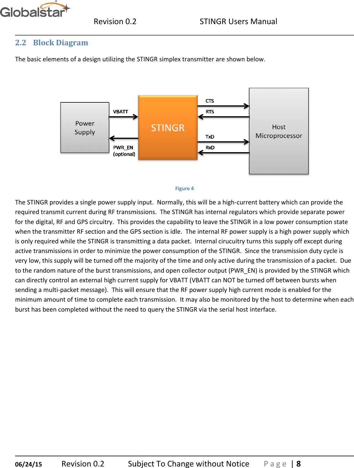
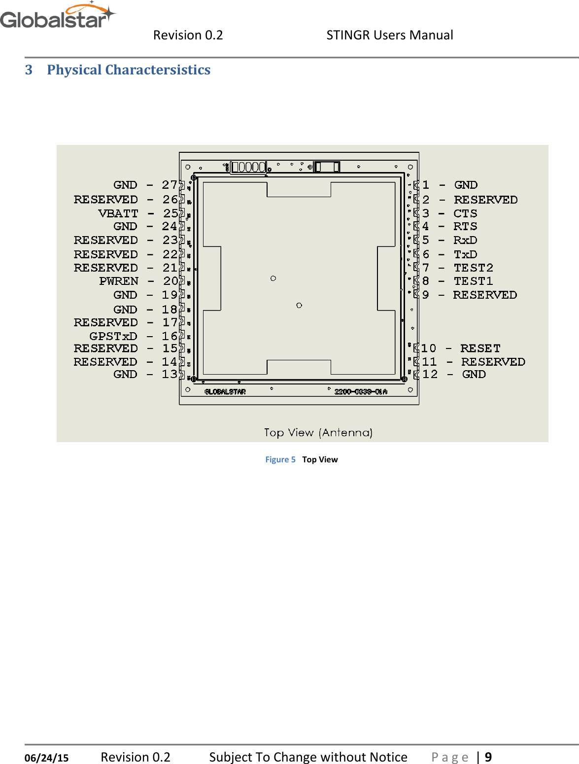
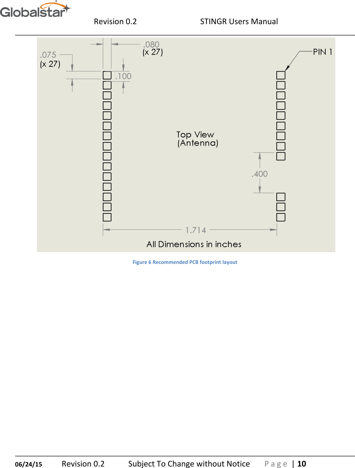
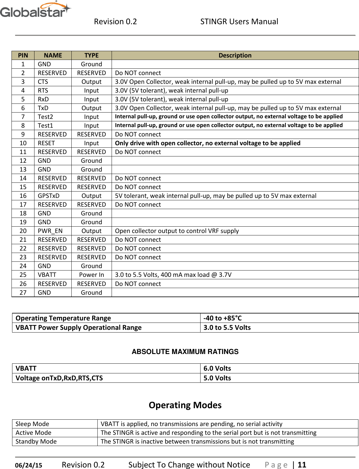
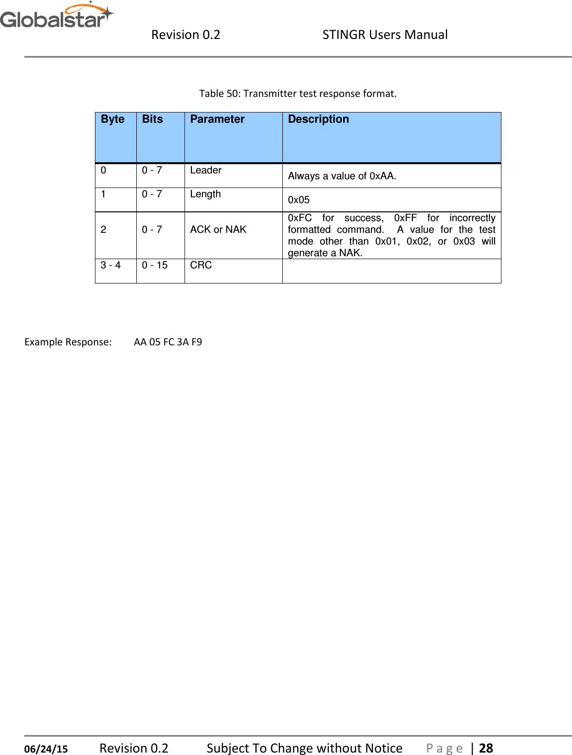
Users Manual
Navigation menu
Upload a User Manual
Namespaces
Wiki Guide
HTML
PDF
Info
Views
User Manual
Discussion / Help
Navigation
![Revision 0.2 STINGR Users Manual 06/24/15 Revision 0.2 Subject To Change without Notice P a g e | 29 5.4 Example CRC calculation routines for serial packets The following example is written in the C programming language where: int = 32 bits, short = 16 bits, char = 8 bits unsigned short crc16_lsb(unsigned char *pData, int length) { unsigned char i; unsigned short data, crc; crc = 0xFFFF; if (length == 0) return 0; do { data = (unsigned int)0x00FF & *pData++; crc = crc ^ data; for (i = 8; i > 0; i--) { if (crc & 0x0001) crc = (crc >> 1) ^ 0x8408; else crc >>= 1; } }while (--length); crc = ~crc; return (crc); } USAGE: calculate the CRC for a message and update the message CRC unsigned short crc = crc16_lsb(msg, msg [1]-2); msg [msg [1]-2] = (unsigned char) (crc&0xFF); msg [msg [1]-1] = (unsigned char) (crc>>8);](https://usermanual.wiki/Spot/STGR/User-Guide-2709484-Page-29.png)
![Revision 0.2 STINGR Users Manual 06/24/15 Revision 0.2 Subject To Change without Notice P a g e | 30 The following example is written in the Java programming language: char crc16_lsb(byte pData[], int length) { int pData_i = 0; char s1,s2; byte i; char data, crc; crc = (char) 0xFFFF; if (length == 0) return 0; do { data = (char)((char)0x00FF & pData[pData_i++]); crc = (char)(crc ^ data); for (i = 8; i > 0; i--) { if ((crc & 0x0001) != 0) crc = (char)((crc >> 1) ^ 0x8408); else crc >>= 1; } }while (--length != 0); crc = (char)~crc; return (crc); } USAGE: calculate the CRC for a message and update the message CRC byte msg[]; int len; char crc = crc16_lsb(msg,len-2); msg[len-2] = (byte)((short)crc & (short)0xff); msg[len-1] = (byte)((short)crc >> 8);](https://usermanual.wiki/Spot/STGR/User-Guide-2709484-Page-30.png)