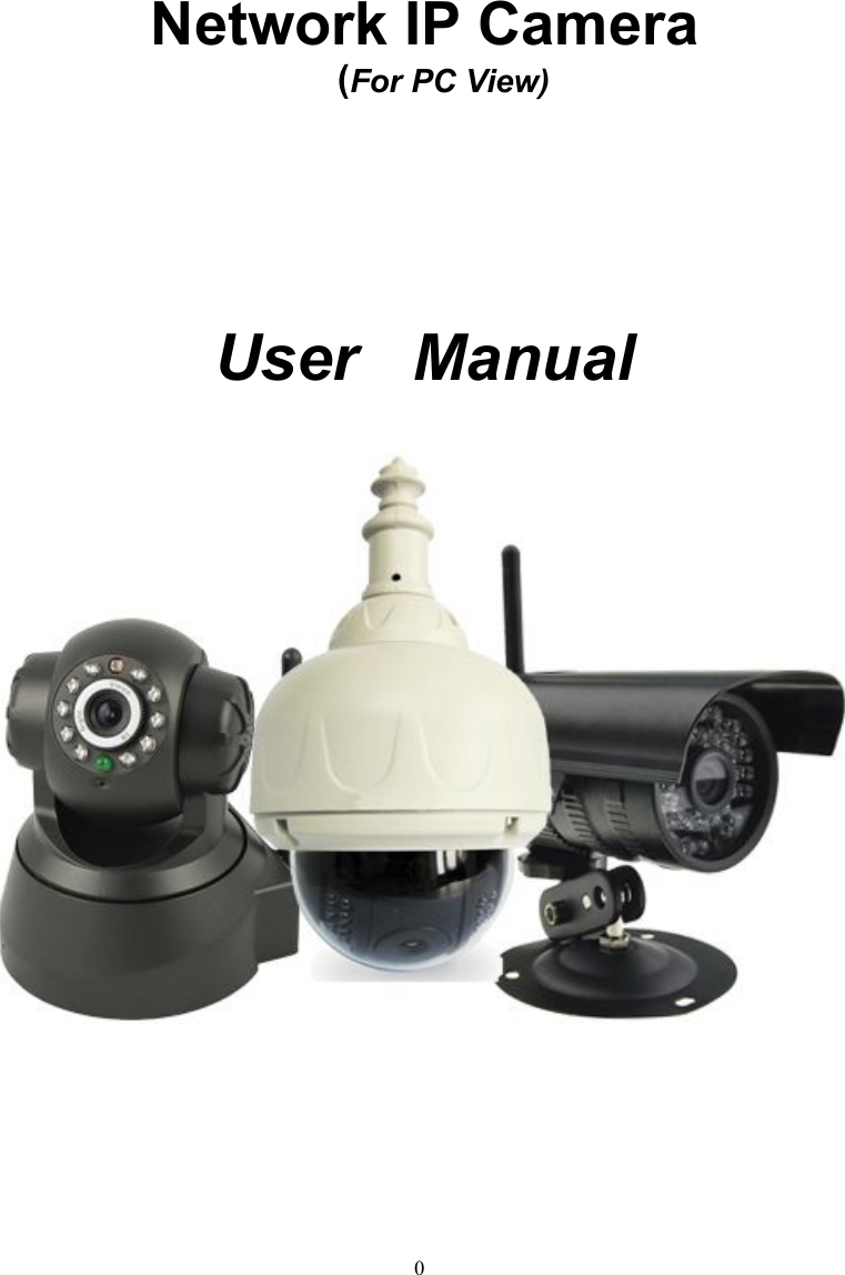
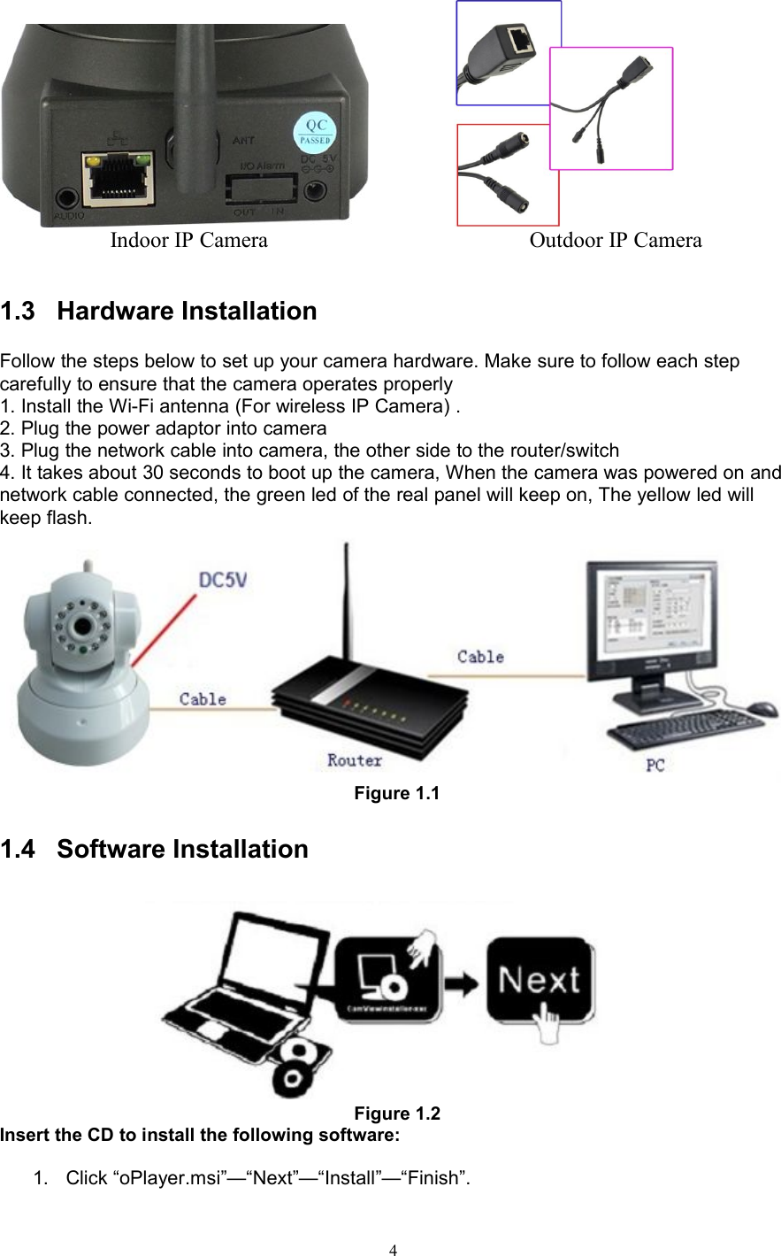
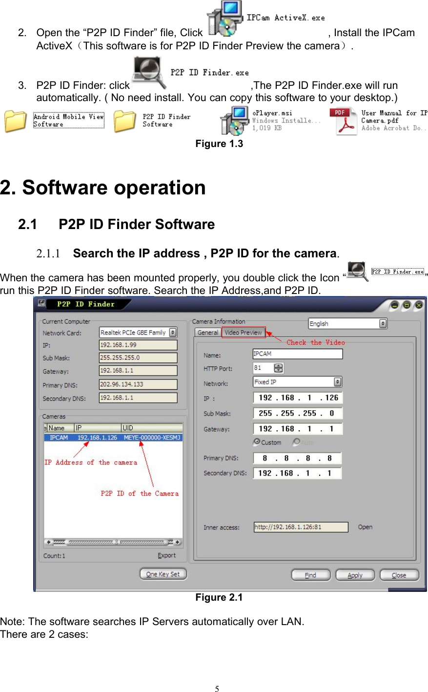
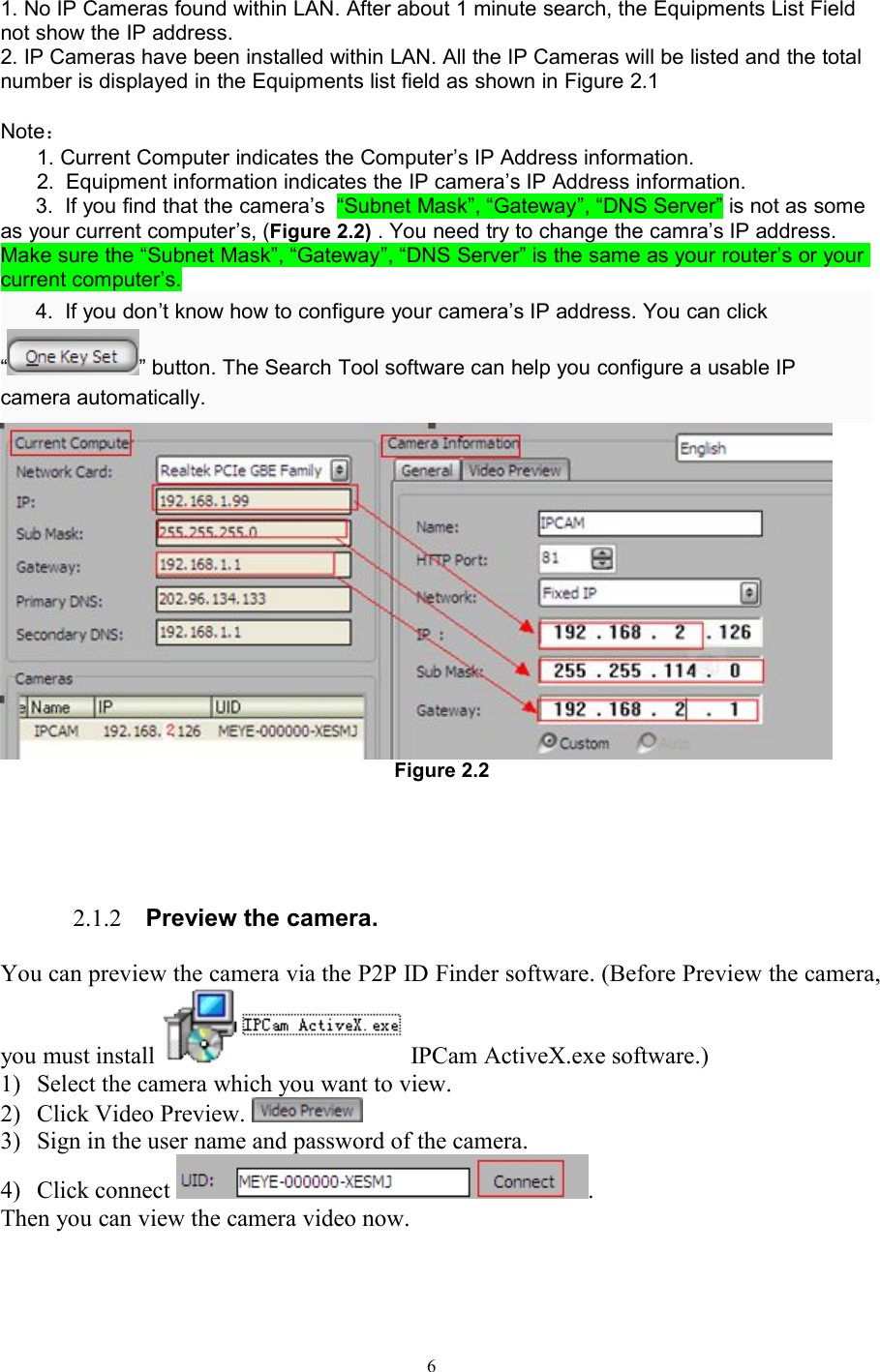
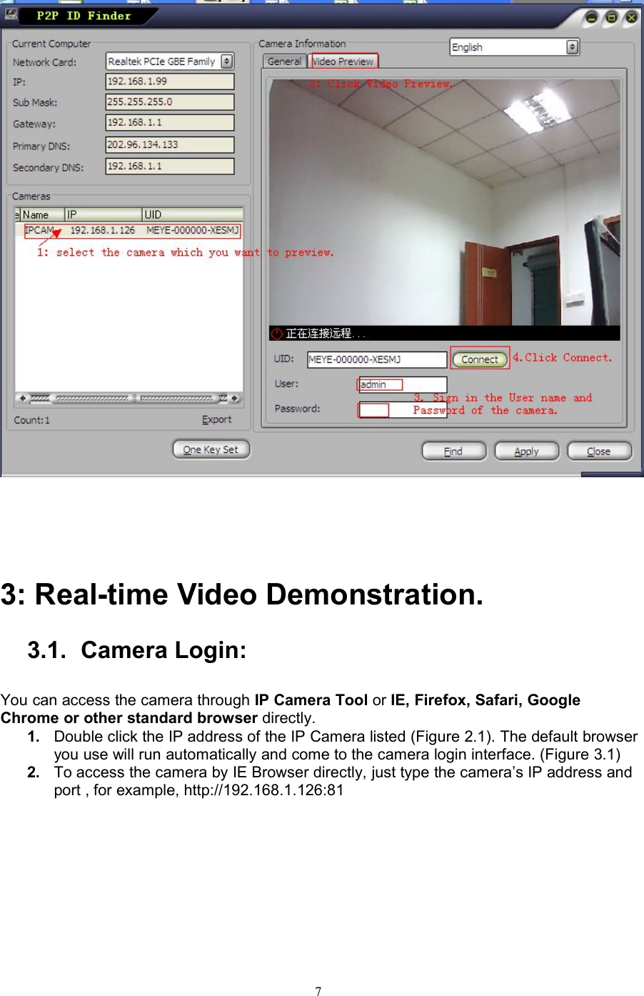
Sricctv Technology AP011 IP Camera User Manual
Shenzhen Sricctv Technology Co., Ltd. IP Camera Users Manual
UserManual.wiki
>
Sricctv Technology
>
AP011 User Manual
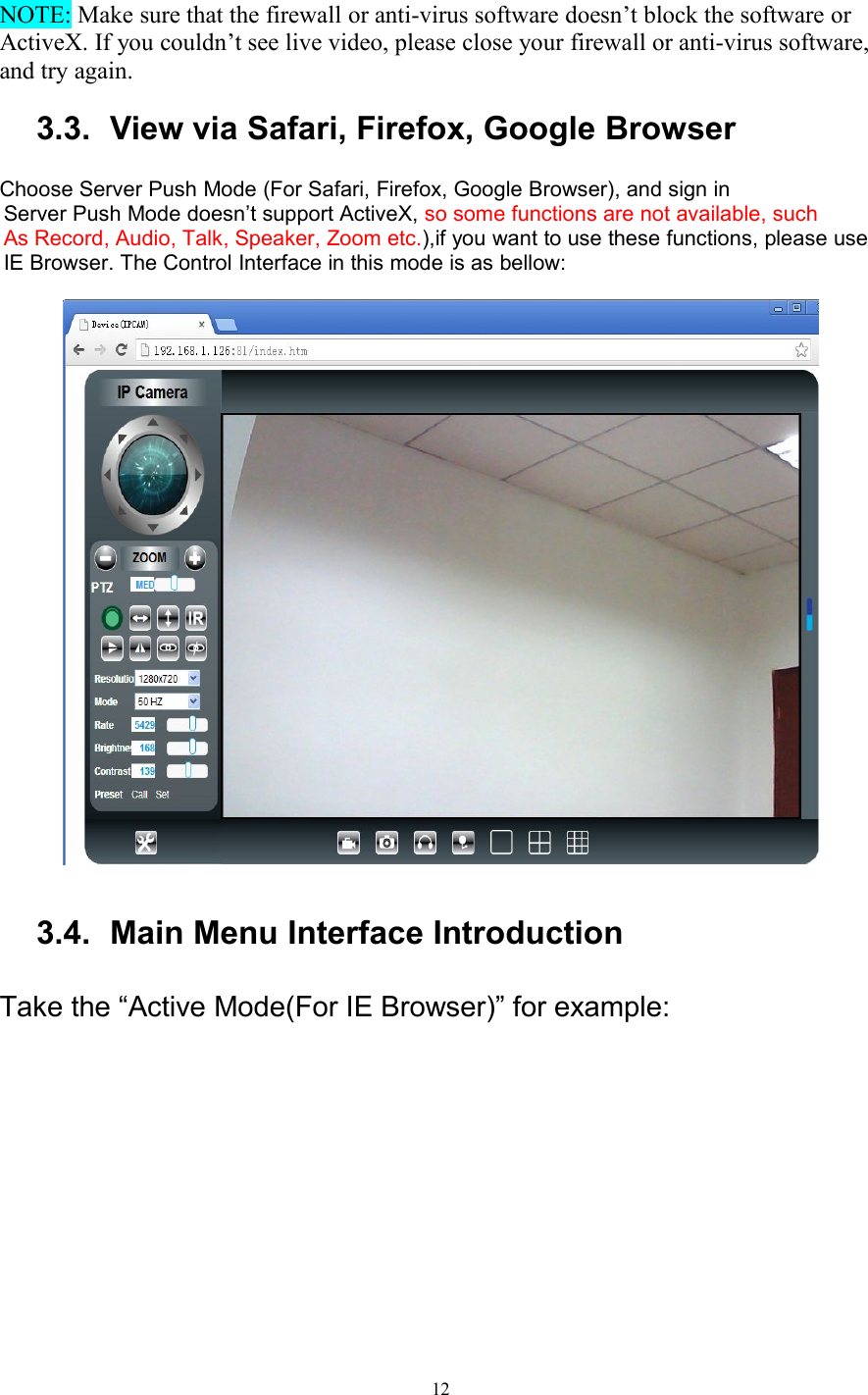
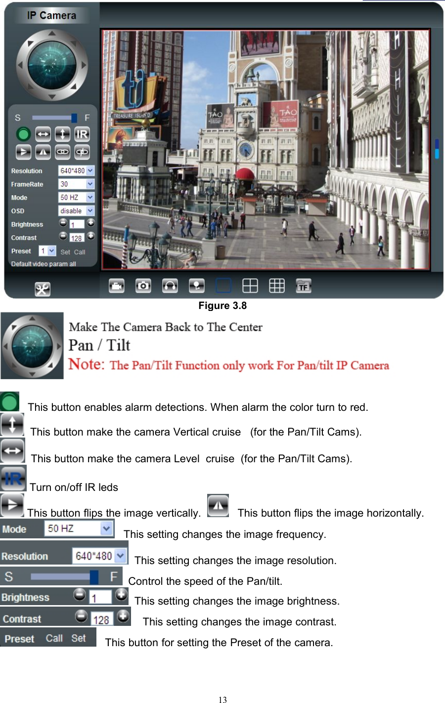
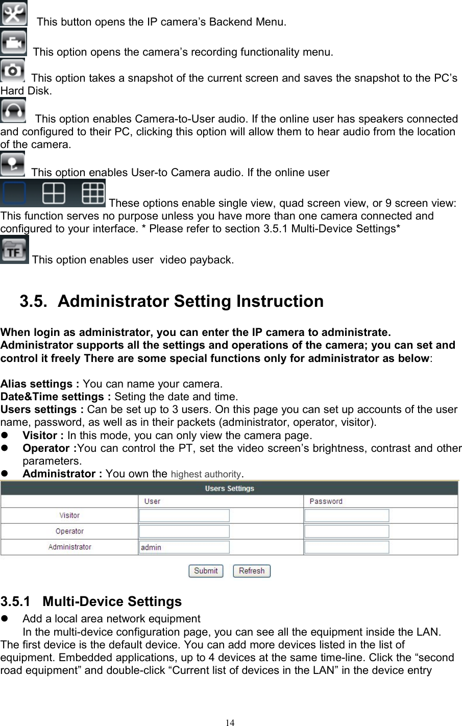
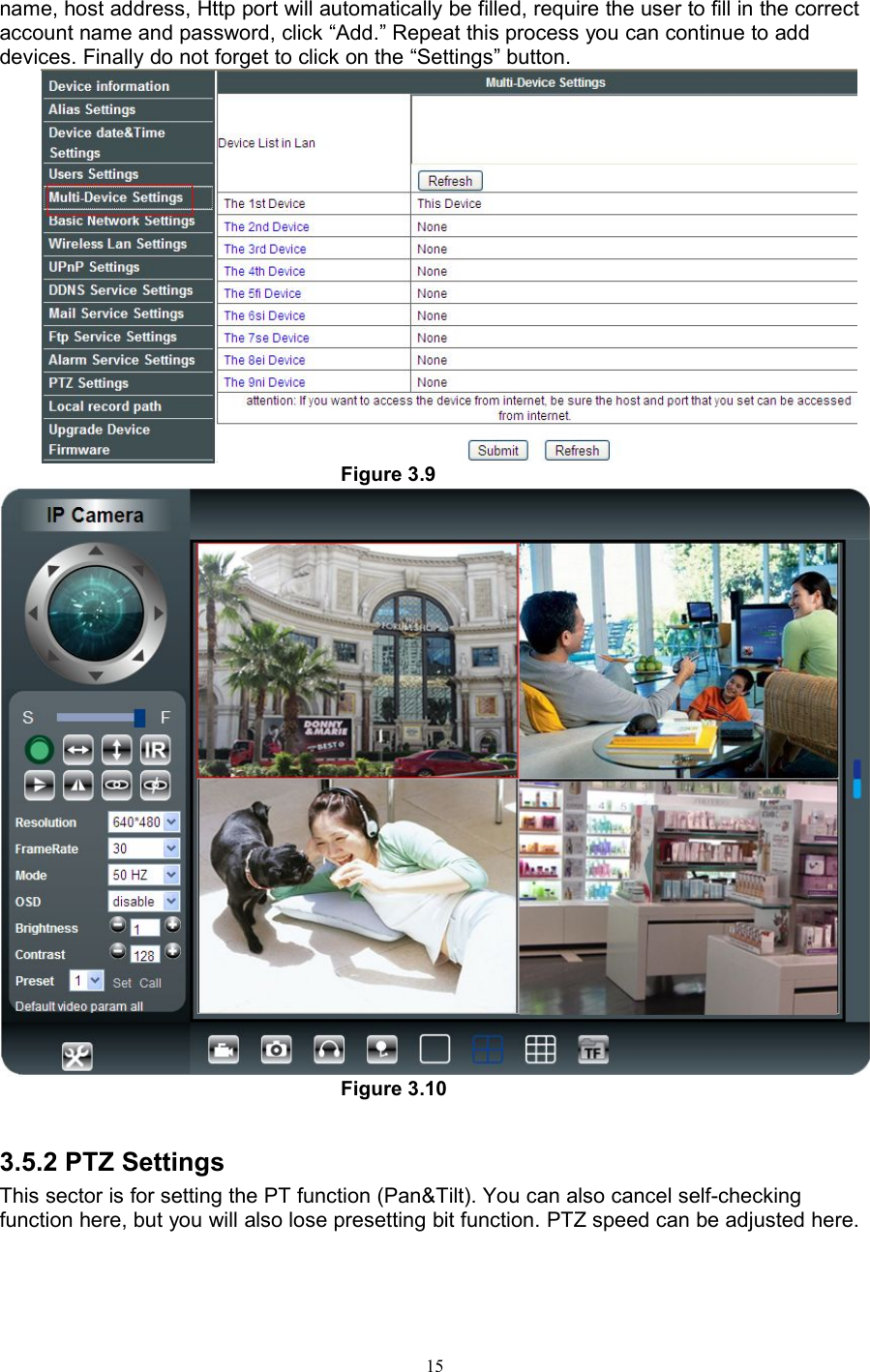
Users Manual
Navigation menu
Upload a User Manual
Namespaces
Wiki Guide
HTML
PDF
Info
Views
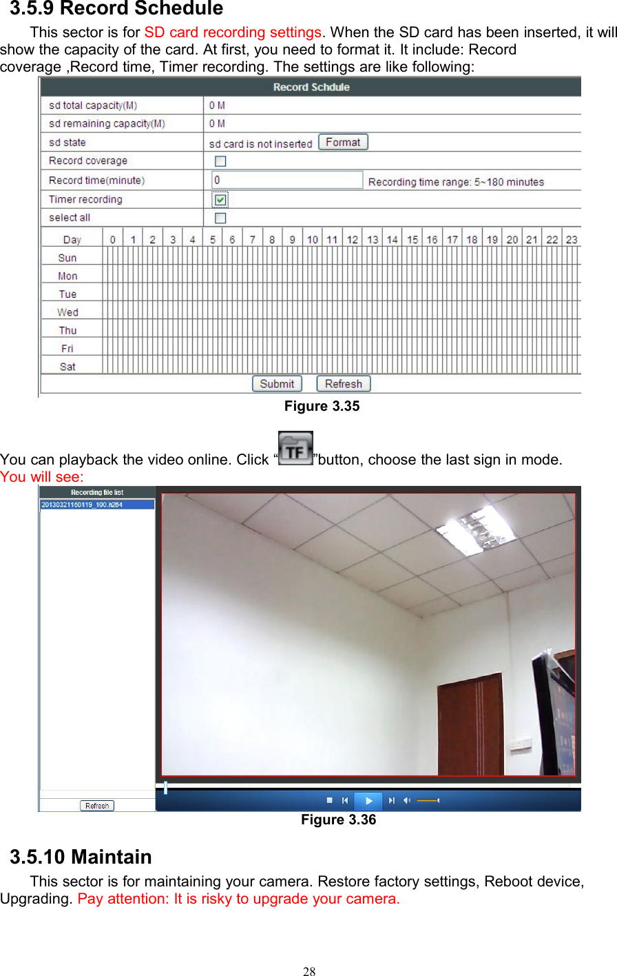
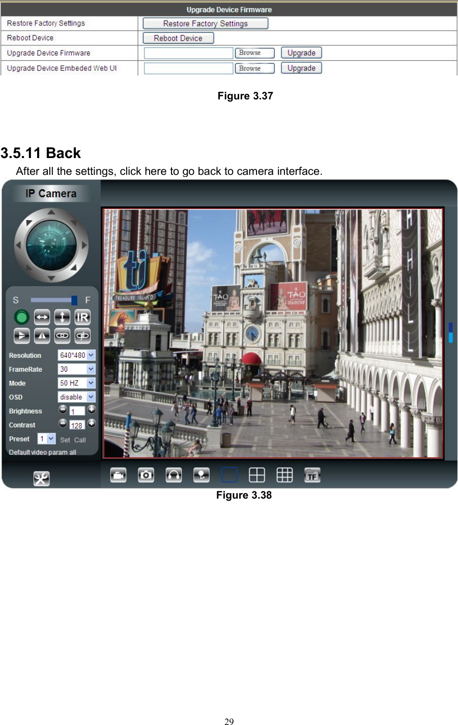
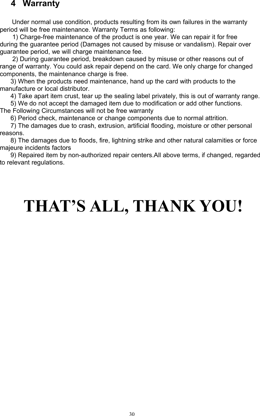
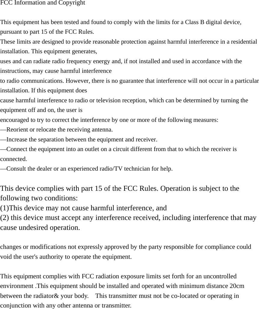
User Manual
Discussion / Help
Navigation