St Jude Medical 01080410 PressureWire® Aeris User Manual Users manual
St Jude Medical Systems AB PressureWire® Aeris Users manual
Users manual
1(17)
Instruction for Use PressureWire® Aeris, 20828 Rev 0F;
will be released as Rev 01
(Generated from approved Master Labeling Specification PW Aeris Rev 07F)
Table of Contents
CONTENTS
DESCRIPTION
1. INDICATION FOR USE
2. CONTRAINDICATIONS
3. GENERAL WARNINGS
4. GENERAL PRECAUTIONS
5. ADVERSE EVENTS
6. PREPARATIONS FOR USE
7. DIRECTIONS FOR USE, CORONARY MEASUREMENTS
8. DIRECTIONS FOR USE, INTERVENTIONAL PROCEDURE
9. DIRECTIONS FOR USE, INTRACARDIAC MEASUREMENTS
PRESSURE PERFORMANCE SPECIFICATION
RADIO SIGNAL SPECIFICATION
FCC STATEMENT
TRANSPORT
STORAGE
TRANSMITTER LIGHT INDICATORS
COMPLIANCE WITH REGULATORY REQUIREMENTS
RoHS DECLARATION (for Chinese IFU only)
PATENTS
WARRANTY AND LIMITATIONS
SYMBOLS WITH EXPLANATIONS
CONTENTS
- 0.014” (0.36 mm) guidewire
- Disconnectable transmitter – to be used with the guidewire it is delivered with
- Torque device
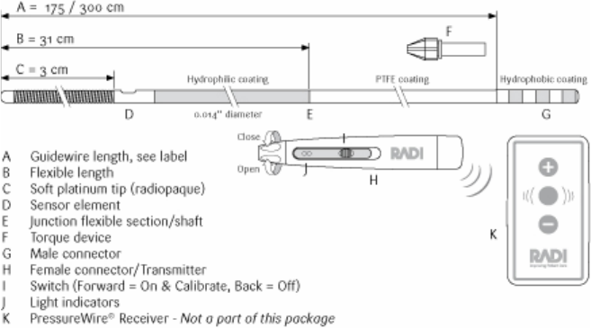
DESCRIPTION (See Diagram 1)
- PressureWire® 0.014” (0.36 mm) is a guidewire with a high fidelity sensor
located just proximal to the 3 cm radiopaque shapeable tip.
- PressureWire® has a nominal diameter of 0.014” (0.36 mm).
- Refer to product label for guidewire length.
- The signals from the sensor can be used for measurements of cardiac and
intravascular blood pressure and estimations of Fractional Flow Reserve
(FFR).
2(17)
Diagram 1: PressureWire®
1. INDICATION FOR USE
PressureWire® is indicated to direct a catheter through a blood vessel and to
measure physiological parameters in the heart and in the coronary and peripheral
blood vessels.
2. CONTRAINDICATIONS
PressureWire® is contraindicated for use in the cerebral vasculature.
3. GENERAL WARNINGS
- PressureWire® is intended for single use only.
- Do not resterilize or reuse: the contents may be damaged or distorted.
- Prior to use and when possible during the procedure, inspect PressureWire®
carefully for bends, kinks or other damage. Do not readjust any bend or kink.
- PressureWire® must not be used if it has been damaged in any way;
otherwise, vessel/ventricle damage and/or inaccurate pressure signals or
inaccurate torque response may occur.
- When introducing PressureWire® in a diagnostic case, flush the catheter and
administer anticoagulation as for a standard catheterization procedure or
clotting may occur.
- Do not torque PressureWire® without observing corresponding movement of
the tip; otherwise vessel/ventricle trauma may occur.
3(17)
- Always advance or withdraw PressureWire® slowly. Never push, withdraw or
torque PressureWire® if it meets resistance.
4. GENERAL PRECAUTIONS
- Federal (USA) law restricts this device to sale by or on the order of a
physician.
- PressureWire® is only intended to be used with PressureWire® Receiver.
- PressureWire® shall not be used with any other transmitter than the one which
it is delivered with, or unreliable readings will be registered.
- Refer to instructions supplied with any interventional devices to be used in
conjunction with PressureWire® for their intended uses, contraindications and
potential complications.
- Do not use PressureWire® with atherectomy catheters. These systems may
cause PressureWire® to fold back upon itself and become lodged in the
atherectomy catheter. If this occurs, withdraw both the atherectomy catheter
and PressureWire® simultaneously.
- PressureWire® does not give sufficient support for guiding catheter exchange.
- Do not use with interventional devices with a too short guidewire rail length as
PressureWire® may fold or fracture during manipulation.
- Confirm the compatibility of PressureWire® diameter with the interventional
device before actual use.
- Free movement of the guidewire within the interventional device is an
important feature of a steerable guidewire system because it gives the user
valuable tactile information. Test the system for any resistance prior to use.
- Adjust or replace the hemostatic valve with an adjustable valve if it is found to
inhibit guidewire movement.
- When PressureWire® is disconnected from the transmitter during the
procedure make sure the male connector does not come into contact with
conductive surfaces thus avoiding unintentional connection with other
equipment.
- False pressure readings may occur if the male connector is:
- not dry, clean and free of coagulated blood.
- not fully inserted into the bottom of the transmitter (indicated by yellow
light).
- bent or damaged.
4(17)
- The PressureWire® Transmitter housing is protected against the effects of a
discharge of a cardiac defibrillator. PressureWire® readings may however be
affected by defibrillation. Attempt recalibration
of PressureWire® after defibrillation according to “Recalibration” in the section
Preparation for use.
- Avoid abrasion of PressureWire® coating. To avoid guidewire damage and
possible shearing of the polymer coating, do not withdraw or manipulate
PressureWire® in a metal cannula or sharp-edged object.
- If PressureWire® is taken out during the procedure in order to be reintroduced
into the patient make sure the PressureWire® distal part is kept wet in the
meantime. Make sure that the transmitter is kept dry.
- For optimal pressure measurement adjust the position of PressureWire® so
that the sensor does not touch the atrial or ventricular walls, to avoid
measurement artefacts due to movement.
- After use, the product may be a potential biohazard. Handle and dispose of
PressureWire® in accordance with medical practice and applicable local, state
and federal laws and regulations.
NOTE:
The transmitter contains silver oxide button type batteries with in total < 2% mercury,
allowed to be put on the market according to the battery directive 2006/66/EG.The
signal performance requires the batteries to be permanently affixed and the
transmitter to be sealed, which, according to article 11 in the same directive, exclude
the batteries from the requirement to be possible to remove. Dispose as ordinary
potentially biohazardous material.
5. ADVERSE EVENTS
Potential complications which may be encountered during all catheterization
procedures include but are not limited to: vessel dissection or occlusion,
perforation, embolus, spasm, local and/or systemic infection, pneumothorax,
congestive heart failure, myocardial infarction, hypotension, chest pain, renal
insufficiency, serious arrhythmias or death.
6. PREPARATIONS FOR USE
Open the PressureWire® package using sterile technique and place
PressureWire®, still attached to the packaging tray, on the sterile field.
- Make sure that PressureWire® is fully inserted into the transmitter.
- Fill the packaging coil with 10 ml (10 cc) of saline solution through the flush
port located at the very inside of the coil on the packaging tray.
5(17)
- Take care that the sensor element of PressureWire® is just submerged but not
under a column of liquid (the tray should be lying flat).
- Activate the receiver by pressing the CONNECT button. The receiver is now
ready to connect to PressureWire® (during 60 s), indicated by a flashing green
light.
- Turn the transmitter on by pushing the slide button forward. A green light is
activated. PressureWire® will now calibrate and search for a connection with
the receiver.
- After successful calibration and connection to the receiver, the receiver
indicators shift to steady green light and a double beep is heard.
o If calibration fails the transmitter light turns yellow.
o If a connection is not established and the green light on the receiver is
still flashing, restart the transmitter by turning it off and then on again.
o If a connection is not established within 60s the receiver returns to
standby mode, indicated by a yellow light and a long beep. Reactivate
the receiver by pressing the CONNECT button, then restart the
transmitter by turning it off and then on again.
- After calibration, confirm that the pressure reading on the cathlab monitor is
zero; re-zero the cathlab pressure channel if necessary. PressureWire® is now
ready for use.
- Avoid turning off the transmitter during the case since PressureWire® will
require a recalibration outside of the body.
o RECALIBRATION
If recalibration is necessary during the case, remove PressureWire®
from the body and turn the transmitter off and then on again.
- Gently detach the transmitter from the packaging tray and carefully pull out the
wire from the coil.
- Refer to Instructions for use for PressureWire® Receiver for complete
instructions on handling of the receiver.
WARNING:
PressureWire® is a delicate instrument and should be handled carefully. Bending
or excessive force during removal from packaging tray may damage the
guidewire.
6(17)
7. DIRECTIONS FOR USE, CORONARY MEASUREMENTS
7.1. Engage the guiding catheter using standard practice. Flush the catheter.
CAUTION:
A guiding catheter with 6F (2 mm) size or larger should be used to prevent
damping of the arterial pressure signal. Larger size should be considered when
large interventional catheters are used.
7.2. Carefully insert the distal tip of the guidewire into the hemostatic valve of
the Y connector and then advance the wire into the catheter.
7.3. Position the sensor element of PressureWire® just outside of the tip of the
guiding catheter.
7.4. Pull back the insertion tool out of the hemostatic valve.
7.5. Tighten the hemostatic valve.
7.6. Place the aortic pressure transducer at the same height as the patient´s
heart. Make sure there is no remaining contrast fluid in the catheter, flush if
necessary.
7.7. Verify that the aortic pressure from the guiding catheter and the
PressureWire® pressure are similar.
7.8. To remove any residual pressure difference between aortic and
PressureWire® pressure use the equalization function on the Cathlab
monitor system or use the plus (+) and minus (–) buttons on
PressureWire® Receiver. Refer to the Instructions for use for the Cathlab
monitor or the Instructions for use for PressureWire® Receiver.
WARNING:
When introducing the guidewire, confirm that the catheter tip is free within the
vessel lumen and not against the vessel wall. Failure to do so may result in vessel
trauma upon guidewire exit of the catheter. Use the radiopaque marker of the
catheter to confirm position.
7.9. Advance PressureWire® out of the guiding catheter. Use the torque device
to steer PressureWire® to the desired position and perform pressure
measurement.
WARNING:
Observe all PressureWire® movement. Whenever PressureWire® is moved or
torqued, the tip movement should be examined under fluoroscopy.
CAUTION:
When difficult to reach a desired position, PressureWire® may be disconnected for
7(17)
better handling. Carefully wipe and then dry the male connector before it is
reconnected.
WARNING:
Torquing PressureWire® against resistance or repeated attempts to cross a total
vessel occlusion may cause damage and/or fracture, which may lead to a portion of
PressureWire® separating from the tip.
NOTE: To calculate Fractional Flow Reserve (FFR) apply maximum hyperemic
stimulus according to clinical standard practice.
CAUTION:
Failure to achieve maximum coronary and myocardial hyperemia may result in invalid
FFR.
CAUTION:
Do not measure pressure when the sensor element of PressureWire® is in sharp
curves, since this might result in pressure artefacts.
WARNING:
Excessive manipulation when sensor element (D) or tip of PressureWire® is located
in sharp bend may cause damage or tip fracture. If the guiding catheter is in an
anatomically severe or sharp bend, for example a tortuous subclavian artery or
adjacent vessel position, the junction between the shaft and the flexible distal section
of the wire (E), 31 cm from the tip, may be vulnerable to kinking or fracture. Avoid
use of PressureWire® via a radial or brachial approach unless this approach is based
on medical necessity.
If a decision is taken to continue with an interventional procedure, follow these
instructions:
8. DIRECTIONS FOR USE, INTERVENTIONAL PROCEDURE
CAUTION:
A guiding catheter with 6F (2 mm) size or larger should be used to prevent damping
of the arterial pressure signal. Larger size should be considered when large
interventional catheters are used.
8.1 Inspect and prepare the interventional device according to the manufacturer’s
instructions.
8.2 Disconnect the transmitter from PressureWire®, then remove the torque device by
loosening the screw and gently withdraw it.
8.3 Carefully advance the interventional device over PressureWire® male connector
and proceed according to standard clinical practice.
8.4 Carefully wipe and then dry the male connector before it is reconnected.
8(17)
8.5 Reconnect PressureWire® to the transmitter, taking care to gently and fully insert
the male connector and to tighten the cap on the transmitter.
8.6 Treat the lesion using standard practice.
8.7 To evaluate the result of the intervention, withdraw the interventional device and
perform pressure measurement.
CAUTION:
An interventional device may cause an underestimation of coronary pressure if left in
artery or guiding catheter during pressure measurement.
NOTE: To calculate Fractional Flow Reserve (FFR) apply maximum hyperemic
stimulus according to clinical standard practice.
CAUTION:
Failure to achieve maximum coronary and myocardial hyperemia may result in invalid
FFR.
8.8 When the procedure is finished, verify pressures by:
o Position the sensor element of PressureWire® just outside of the tip of the
guiding catheter.
o Flush any remaining contrast fluids.
o Pull back the insertion tool out of the hemostatic valve.
o Tighten the hemostatic valve.
o Verify that the pressures registered by the guiding catheter and
PressureWire® are the same.
9. DIRECTIONS FOR USE, INTRACARDIAC MEASUREMENTS
WARNING:
When introducing the guidewire, confirm that the catheter tip is free within the heart
lumen and not against the heart wall. Failure to do so may result in ventricle trauma
upon guidewire exit of the catheter.
WARNING:
Torquing PressureWire® against resistance may cause damage and/or fracture of
PressureWire®, which may lead to a portion of PressureWire® separating from the
tip.
WARNING:
Positioning of catheters and guide wires in the ventricles is potential arrhythmogenic.
It should never be done without ECG monitoring and the presence of a functioning
defibrillator.
9(17)
WARNING:
Avoid using PressureWire® in the ventricles if the patient has a prosthetic
mechanical valve. PressureWire® may become trapped and disrupt the function of
the valve, leading to serious injury or death.
CAUTION:
A standard 0.035” J-shaped guidewire is recommended to advance the catheter and
to give support when crossing heart valves. Never use PressureWire® for this
purpose.
9.1 Use a standard 0.035” J-shaped guidewire to position a multipurpose catheter in
the heart at the position of interest, follow standard clinical practice depending on
application.
9.2 With the catheter securely in place, replace the standard guidewire with
PressureWire®.
9.3 Insert the distal tip of PressureWire® into the hemostatic valve and then advance
the wire into catheter.
9.4 Advance PressureWire® into the position of interest.
WARNING:
Observe all PressureWire® movement. Whenever PressureWire® is moved or
torqued, the tip movement should be examined under fluoroscopy.
9.5 Pull back the catheter to a stable position outside the heart valve, leaving only
PressureWire® at the measurement position.
CAUTION:
Whenever absolute blood pressure measurements are obtained, the pressure
registered by the catheter and PressureWire® should be properly matched. For this
purpose the catheter should have a residual lumen large enough to prevent damping
of the corresponding intracardiac pressure.
PRESSURE PERFORMANCE SPECIFICATION
Operating pressure: -30 to +300 mmHg
Zero Thermal Effect: 0.3 mmHg/°C
Sensitivity Thermal Effect: 0.3%/°C
Zero drift: < 7mmHg/h
Total Accuracy for the combination
of PressureWire® and PressureWire® Receiver:
±1mmHg plus ±1% of reading (over the
pressure range – 30mmHg to 50mmHg)
±3% of reading (over the range 50mmHg to
300mmHg)
10(17)
Delay time: <10 ms
Typical performance data for pressure is valid in the temperature range of 35°C to
42°C during a measuring time of less than 1 hour.
RADIO SIGNAL SPECIFICATION
Frequency Range: 2.4000-2.4835GHz (ISM-band)
Type: Frequency Hopping Spread Spectrum
Radiated power: 1mW peak, 70µW average (EIRP)
Range: 0 - 2m
Note: Radio range is reduced by objects and walls, keep transmitter and receiver in
line of sight wherever possible.
FCC STATEMENT
FCC ID: U4L01080410 FCC identifier for the transmitter
This device complies with part 15 of the FCC Rules. Operation is subject to the
following two conditions: (1) This device may not cause harmful interference, and (2)
this device must accept any interference received, including interference that may
cause undesired operation.
WARNING - Changes or modifications not expressly approved by Radi Medical
Systems AB could void the user´s authority to operate the equipment.
ENVIRONMENTAL CONDITION
Ambient temperature: 15-35°C
Ambient temperature fluctuation : ± 5°C
Relative air humidity: 30- 75%
Ambient pressure: 425-850 mmHg
TRANSPORT
Transportation temperature: -25- 70°C
Relative air humidity: 10- 95%
STORAGE
Store at room temperature in a dry, dark place.

11(17)
TRANSMITTER LIGHT INDICATORS
Light indicators Explanation
Green steady light Transmitter on
Green pulsating light
proportional to blood pressure
Normal operation
Yellow steady light PressureWire® disconnected from transmitter.
Re-insert PressureWire® firmly into transmitter.
Green pulsating light &
Yellow slow blinking light
Battery level low
It is recommended to finish case or to exchange
PressureWire®.
Yellow fast blinking light Error. Possible cause:
o Battery level too low for operation
o Internal error
Attempt restart by removing PressureWire from
body and turn the transmitter off and on again.
COMPLIANCE WITH REGULATORY REQUIREMENTS
Hereby, Radi Medical Systems AB, declares that this PressureWire® is in
compliance with the essential requirements and other relevant provisions of Medical
Device Directive (93/42/EEC), Radio and Telecommunications Terminal Directive
(199/5/EC) and QSR
Guidance and manufacturer's declaration - electromagnetic emissions
PressureWire® system is intended for use in the electromagnetic environment specified below. The
customer or the user of PressureWire® system should assure that it is in such an environment.
Emission test Compliance Electromagnetic environment -
guidance
RF emissions
CISPR 11
Group 1
The PressureWire® system uses RF energy only
for its internal function. Therefore, its RFemissions
are very low and are not likely to cause any
interference in nearby electronic equipment.
RF emissions
CISPR 11
Class B
Harmonic emissions
IEC 61000-3-2
Class A
Voltage fluctuations
/flicker emissions
IEC 61000-3-3
Complies
The PressureWire® system is suitable for use in all
establishments including domestic establishments
and those directly connected to the public low-
voltage power supply network that supplies building
for domestic purposes.
Guidance and manufacturer's declaration - electromagnetic immunity
The PressureWire® system is intended for use in the electromagnetic environment specified below.
The customer or the user of the PressureWire® system should assure that it is in such an
environment.

12(17)
Immunity test
IEC 60601
Test level
Compliance
level
Electromagnetic
environment - guidance
Electrostatic
discharge (ESD)
IEC 61000-4-2
±6 kV contact
±8 kV air
±6 kV contact
±8 kV air
Floors should be wood, concrete
or ceramic tile. If floors are covered
with synthetic material, the relative
humidity should be at least 30%.
Electrical fast
transient/burst
IEC 61000-4-4
±2 kV for power
supply lines
±1 kV for input/
output lines
N/A
1)
2)
N/A
Surge IEC 61000-4-5
±1 kV differential mode
±2 kV common mode
N/A
2)
N/A
Voltage dips, short
interruptions and
voltage variations on
power supply input
lines IEC 61000-4-11
<5% UT
(>95% dip in UT)
for 0,5 cycle
40% UT
(60% dip in UT)
for 5 cycles
70% UT
(30% dip in UT)
for 25 cycles
<5% UT
(>95% dip in UT)
for 5 sec
N/A
1)
N/A
Power frequency
(50/60 Hz)
magnetic filed
IEC 61000-4-8
3 A/m
3 A/m
Power frequency magnetic fields
should be at levels characteristic of a
typical location in a typical commercial
or hospital environment.
NOTE: UT is the a.c. mains voltage prior to application of the test level.
1) No mains power input
2) Patient connection
Guidance and manufacturer's declaration - electromagnetic immunity
The PressureWire® system is intended for use in the electromagnetic environment specified below.
The customer or the user of the PressureWire® system should assure that it is in such an
environment.
Immunity test
IEC 60601
Test level
Compliance
level
Electromagnetic environment
- guidance
Portable and mobile RF
communication equipment should
be used no closer to any part of the
PressureWir® system, including
cables, than the recommended
separation distance calculated from
the equation applicable to the
frequency of the transmitter.
Conducted RF
3 Vrms
N/A
d = 1,2√ P
13(17)
IEC 61000-4-6
150 kHz to 80 MHz
1)
Radiated RF
IEC 61000-4-3
3 V/m
80 MHz to 2,5 GHz
3 V/m
d = 1,2√ P 80 MHz to 800 MHz
d = 2,3√P 800 MHz to 2,5 GHz
Where P is the maximum output
power rating of the transmitter in
watts (W) according to the transmitter
manufacturer and d is the recommended
separation distance in metres (m).
Field strengths from fixed RF transmitters,
as determined by an electromagnetic
site surveya, should be less
than the compliance level in each
frequency rangeb.
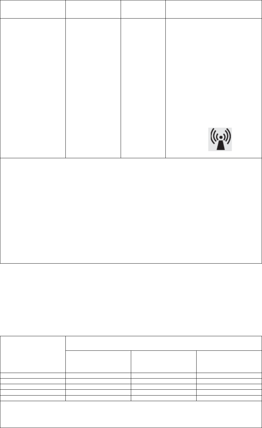
Interference may occur in the vicinity
of equipment marked with the
following symbol:
NOTE 1: At 80 MHz and 800MHz, the higher frequency range applies.
NOTE 2: These guidelines may not apply in all situations. Electromagnetic propagation is affected by
absorption and reflection from structures, objects and people.
a) Field strengths from fixed transmitters, such as base stations for radio (cellular/cordless)
telephones and land mobile radios, amateur radio, AM and FM radio broadcast and TV
broadcast cannot be predicted theoretically with accuracy. To assess the electromagnetic
environment due to fixed RF transmitters, an electromagnetic site survey
the PressureWire® system is used exceeds the applicable RF compliance level above,
the PressureWire® system should be observed to verify normal operation. If abnormal
performance is observed, additional measures may be necessary, such as reorienting
or relocating the PressureWire® system.
b) Over the frequency range 150KHz to 80MHz, field strengths should be less than 3 V/m.
1) No mains power input
Recommended separation distances between portable and mobile RF
communications equipment and the PressureWire® system
The PressureWire® system is intended for use in the electromagnetic environment in which radiated
RF disturbances are controlled. The customer or the user of the PressureWire® system can help
prevent electromagnetic interference by maintaining a minimum distance between portable and mobile
RF communications equipment (transmitters) and the PressureWire® system as recommended below,
according to the maximum output power of the communications equipment.
Separation distance to frequency of transmitter (m)
Rated maximum
output power
of transmitter
W
150 kHz to 80 MHz
d = 1,2√ P
80 MHz to 800 MHz
d = 1,2√ P
800 Mhz to 2,5 GHz
d = 2,3√ P
0,01 0,12 0,12 0,24
0,1 0,38 0,38 0,73
1 1,2 1,2 2,3
10 3,8 3,8 7,3
100 12 12 23
For transmitters rated at a maximum output power not listed above, the recommended separation
distance (d) in metres (m) can be estimated using the equation applicable to the frequency of the
transmitter, where P is the maximum output power rating of the transmitter in watts (W) according
to the transmitter manufacturer.

14(17)
NOTE 1: At 80 MHz and 800 MHz, the separation distance for the higher frequency range applies.
NOTE 2: These guidelines may not apply in all situations. Electromagnetic propagation is affected by
absorption and reflection from structures, objects and people.
RoHS DECLARATION (for the Chinese IFU only)
No toxic and hazardous substances according to RoHS contained.
PATENTS
USA: Re 35648, Re 39863, 4996082, 5085223, 5938624, 6089103,
6112598, 6142958, 6167763, 6196980, 6248083, 6336906,
6409677, 6428336, 6565514, 6615667, 6672172, 6754608,
6908442
Europe: 877574, 907335, 968547, 973438, 1012912, 1076511,
1125548, 1310215, 1475036, 1165171
Canada: 1271930
Sweden: 460396, 506135, 523337
Japan: 2659944, 2719425, 3675835, 3679419, 3692014, 3692035,
3774237, 3830528, 3880884
Other patents pending worldwide
WARRANTY AND LIMITATIONS
Although PressureWire®, hereafter referred to as “product”, has been manufactured
under carefully controlled conditions, Radi Medical Systems AB, hereafter called
Radi, has no control over the conditions under which the product is used. Radi,
therefore disclaims all warranties, both expressed and implied, with respect to the
product, including, but not limited to, any implied warranty of merchantability or
fitness for a particular purpose. Radi shall not be liable to any person or entity for any
medical expenses or any direct, incidental or consequential damages caused by any
use, defect, failure or malfunction of the product, whether a claim for such damages
is based upon warranty, contract, tort or otherwise. No person has any authority to
bind Radi to any representation or warranty with respect to the product. The
exclusions and limitations set out above are not intended to, and should not be
construed so as to contravene mandatory provisions of applicable law. If any part or
term of this Disclaimer of Warranty is held to be illegal, unenforceable or in conflict
with applicable law by court of competent jurisdiction, the validity of the remaining
portions of this Disclaimer of Warranty shall not be affected, and all rights and
obligations shall be construed and enforced as if this Disclaimer of Warranty did not
contain the particular part or term held to be invalid.

15(17)
PressureWire® is developed and manufactured according to Medical Device
Directive, Radio and Telecommunication Terminal Equipment Directive 199/5/EC and
QSR (US).
PressureWire® and RadiAnalyzer® are registered trademarks of Radi Medical
Systems AB.
Designed, developed and manufactured by:
Radi Medical Systems AB
Palmbladsgatan 10, SE-754 50 Uppsala, Sweden
Tel + 46 (0) 18 16 10 00, Fax: 46 (0) 18 16 10 99
e-mail: radi@radi.se
Radi Medical System contacts and further information:
www.radi.se
16(17)
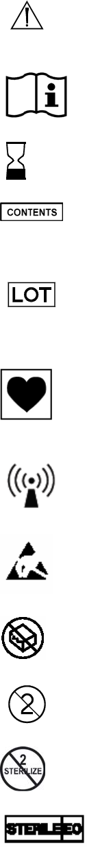
SYMBOLS WITH EXPLANATIONS:
Caution, (Attention consult accompanying documents)
Consult operating instructions
Expiry date (2 years from manufacturing date)
Contents of the package
REF Catalogue number
Lot number.
QTY Quantity
Type CF equipment
Equipment includes RF transmitter
Electrostatic sensitive device
Do not use if package is damaged.
For single use only. Do not reuse.
Do not re-sterilize
Sterilized using Ethylene Oxide

17(17)
The transmitter contains silver oxide button type batteries with in total < 2% mercury,
allowed to be put on the market according to the battery directive 2006/66/EG. The signal
performance requires the batteries to be permanently affixed and the transmitter to be sealed,
which, according to article 11 in the same directive, exclude the batteries from the
requirement to be possible to remove. Dispose as ordinary potentially biohazardous material.
Complies with the Medical Device Directive 93/42/EEC and Radio and
Telecommunication Terminal Equipment Directive 199/5/EC.
FCC ID: U4L01080410 FCC identifier for the transmitter
No toxic and hazardous substances according to RoHS contained.
(This mark for the Chinese market only!)
Rx Only
Caution: Federal law (USA) restricts this device to sale by or on the order of a
Physician
0413