Standard Industrie TELACWCA REMOTE CONTROL FOR AIRCHOC WIRELESS APPLICATION User Manual NOTTELACW US F1
Standard Industrie REMOTE CONTROL FOR AIRCHOC WIRELESS APPLICATION NOTTELACW US F1
User Manual
NOTTELACW-US.doc 1 December 6th, 2012
Produced on: December 6th, 2012
By: DESIGN OFFICE
Checked on:
By: BOISLEUX.M
Signature:
USER
MANUAL
Revision Level: F1
NOTTELACW-US Date: December 6th, 2012
HEAD OFFICE- Standard Industrie : 139-141 rue du Luxembourg-BP50207 59054
ROUBAIX CEDEX 1- FRANCE
+33 (0)3 20 28 32 32 / @ : info@standard-industrie.com

NOTTELACW-US.doc 2 December 6th, 2012
CONTENTS
1 Principle of Airchoc Wireless page 4
2 Principle of remote control page 4
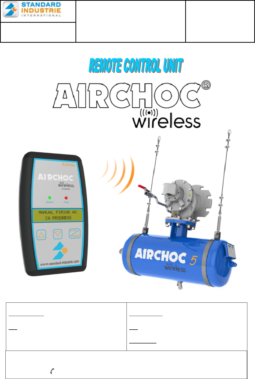
3 Remote Control Unit Presentation page 4
3-1 General Characteristics page 4
4 Installing the Battery and Starting-up page 5
5 Principle page 6
6 Remote Control Unit Indications on Start-up page 6
7 Menu Operation page 6
8 Manual Airchoc Firing page 7
9 Airchoc Consultation page 8
10 Airchoc Isolation page 8
11 Access Code page 9
12 Language Selection page 9
13 Signal Level page 9
14 General Information page 10
14-1 Instructions page 10
14-2 Remote Control Unit Auto Shut-off page 10
14-3 Additional Information page 10
14-4 Using the Battery page 10
14-5 Recycling the Battery and the Remote Control Unit page 10
14-6 Hazard Area page 10
14-7 Warranty page 10
14-8 After Sales Service page 10
NOTTELACW-US.doc 3 December 6th, 2012
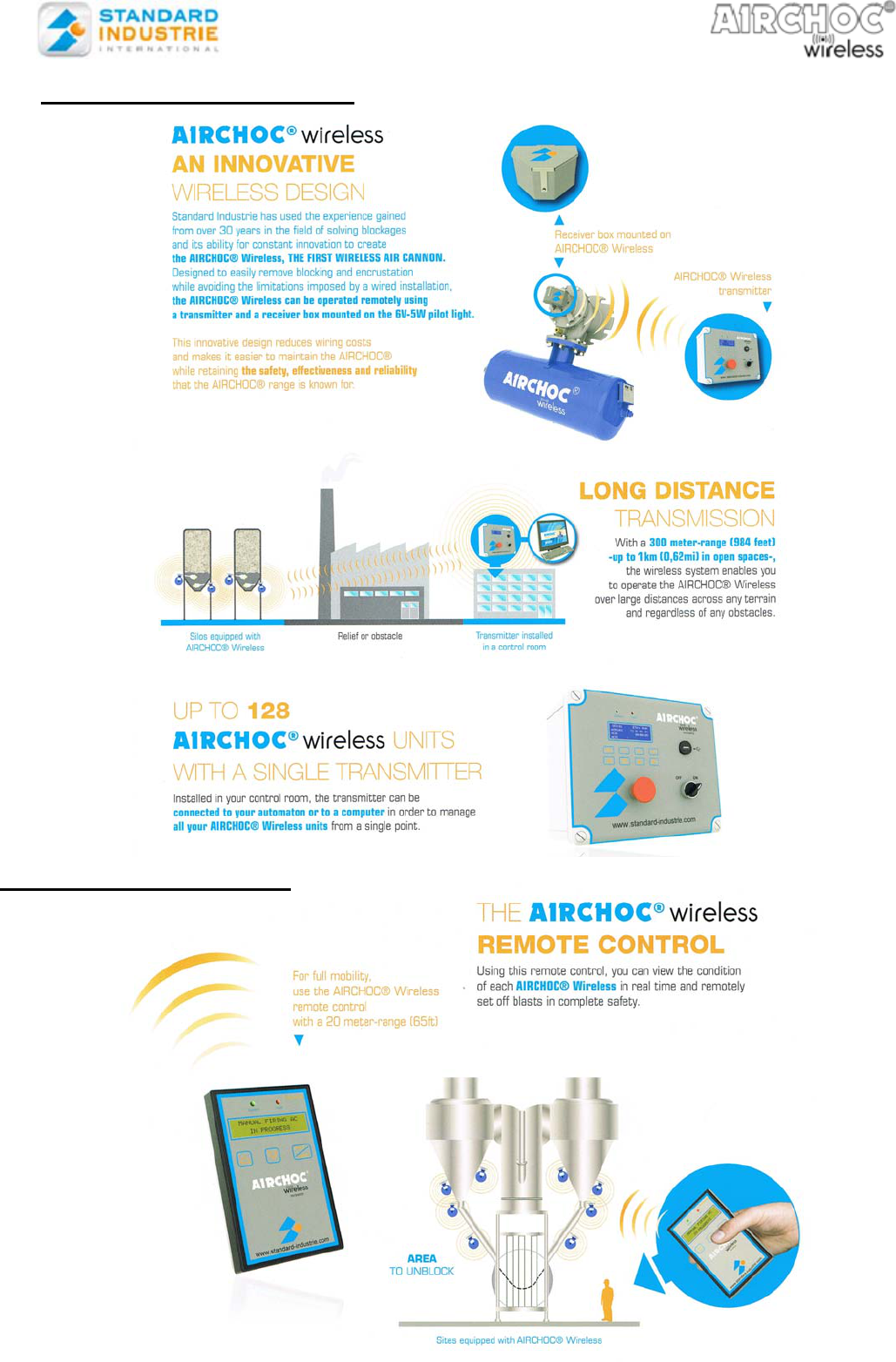
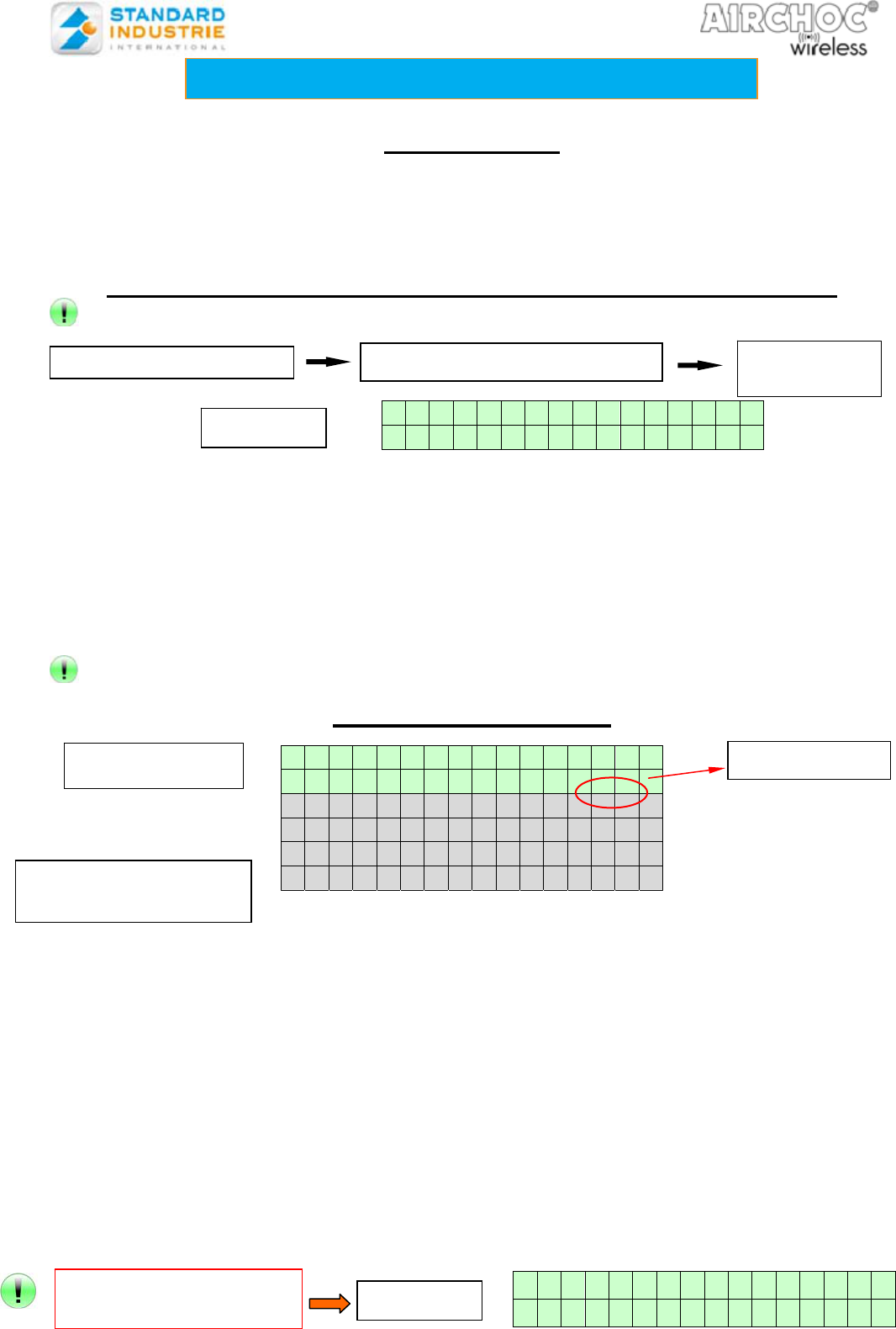
1- Principle of Airchoc Wireless
2- Principle of remote control
NOTTELACW-US.doc 4 December 6th, 2012
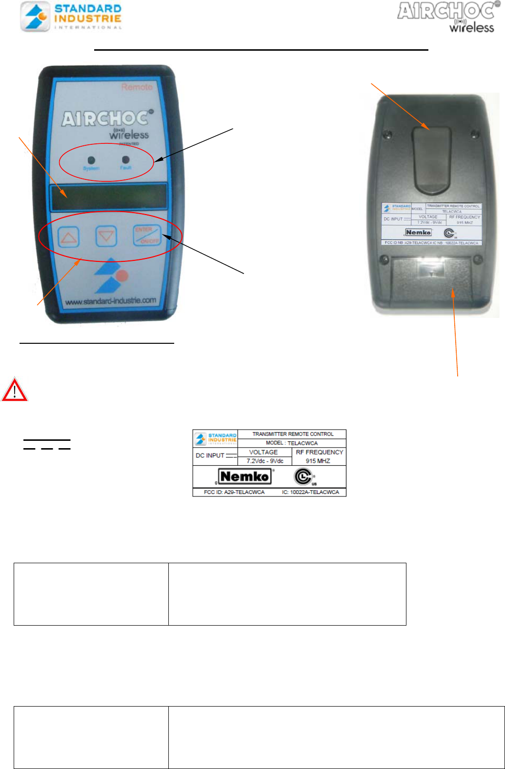
3- REMOTE CONTROL UNIT PRESENTATION
3-1. General Characteristics
3-11. Electrical Characteristics
- Battery supply voltage: 9V dc, type 6LF22 or 6LR61, included,
- Standard Industrie reference: CSMELE9V
Attention, use only alkaline in remote control.
3-12 Explanation of the symbol on the label :
Direct current
This device complies with Part 15 of the FCC Rules. Operation is subject to the following two
conditions: (1) this device may not cause harmful interference, and (2) this device must accept
any interference received, including interference that may cause undesired operation.
3-13. Environmental characteristics:
Attention : it is forbidden to clean the remote control to the high-pressure water.
The protection is impaired if equipment is used in a manner not specified by the
manufacturer.
3-14. Additional Exterior Characteristics
- Operator interface: - 2-line 16-character LCD display with low back lighting
- 3-key keyboard
- Indicator LED:
Green, system (system operational)
Red, fault (fault detected)
- Service temperature:
- Humidity :
- Max altitude
- Pollution degree
Minimum: -10°C
Maximum: +70°C
no more than 80%
e.g up to 2000 m
3
Display
Keyboard
LED
indicator
s
Enter On / Off
Button
9v battery housing
Belt clip
NOTTELACW-US.doc 5 December 6th, 2012
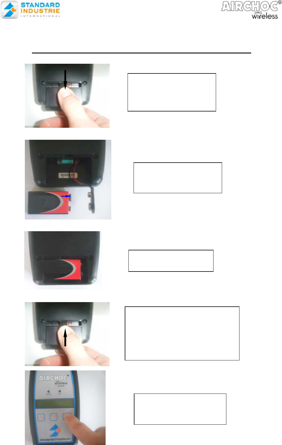
4- INSTALLING THE BATTERY AND STARTING-UP
Remove the battery
compartment cover by
lightly pressing with the
end of your finger.
Connect the 9V battery
to the connector
respecting the polarity.
To close the battery
compartment cover – follow the
slides – lightly press the cover
into place with the end of your
finger
Place the battery in its
compartment
Press the On / Off button
for at least 3 s to start
NOTTELACW-US.doc 6 December 6th, 2012
5-PRINCIPLE:
The wireless remote control unit communicates with receiver units on the Airchocs through the
wireless cabinet. Upon start-up, the remote control unit establishes communications with the
cabinet before becoming functional. If the connection with the cabinet cannot be established, a
communications fault has occurred and the unit cannot function.
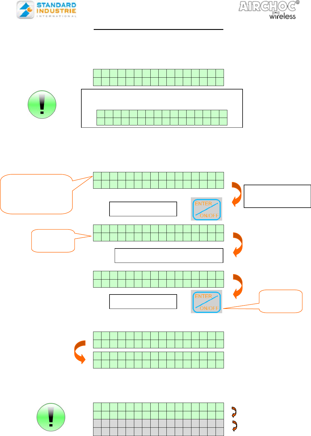
6- REMOTE CONTROL UNIT INDICATIONS ON START-UP
Ensure you are within range of the antenna or router if there is one.
When the remote control unit powers up, the display indicates the software version.
Functions may be accessed using the ▲/▼ keys and the ENTER key.
Generally:
- The ▲ ▼ keys are used for selecting a line or moving left and right
- The ENTER- ON/OFF key is used for:
validating data input (short press <1 s)
start-up / shut-off (press > 3 s)
At any time by pressing ▲ and ENTER you will be returned to the menu
7- MENU OPERATION
The various menus accessible with an access code are in orange (see page 8)
- Manual firing: this menu is used to fire a previously selected Airchoc.
- AC consultation: this menu is used to check whether the Airchocs are active or
inactive.
- AC isolation: this menu is used to activate or deactivate Airchocs for safety
during maintenance.
- Access code: this menu is used to record and modify the access code.
- Language selection: this menu is used to select the display language. English by default
- Signal level: this menu is used to verify the communications level, expressed as
a % from your location with the remote control to the cabinet
antenna module. If you have placed routers, you may do the same
to verify communications between your location with the remote
control and a router in range. This is for informational purposes
only and may vary subject to disturbances.
S o f t v e r s i o n :
1 . 0 4
S h o o t i n g m u n u a l
C o n s u l t a t i o n A C
C o n s i g n m e n t A C
A c c e s s c o d e
L a n g u a g e s e t t i n g
S i g n a l L e v e l
N o s i g n a l
WIRELESS REMOTE CONTROL UNIT
START-UP Press the ON/OFF button for 3 s The green LED
comes on
Display
If the Wireless cabinet
is not on Display
AC Airchoc
(
Visible lines
Grey lines made
visible by scrolling
NOTTELACW-US.doc 7 December 6th, 2012
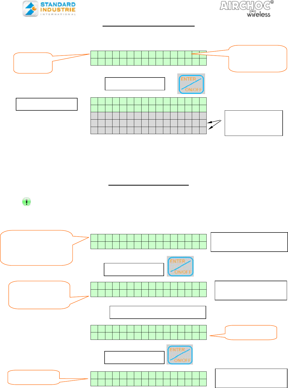
8- MANUAL AIRCHOC FIRING
MENU ACCESSED BY ACCESS CODE
After entering the access code, the remote control unit connects to the cabinet (to view the
accessible Airchocs).
If communications are not good, the display will remain locked on:
S e a r c h
A i r c h o c
CONNECTION ESTABLISHED WITH THE CABINET
When the connection is established, the display indicates the Airchocs registered with the
cabinet:
- - > 0 0 1 X X X X
0 0 2 X X X X
S h o o t i n g f o r X X X X
Q u i t V a l i d
S h o o t i n g f o r X X X X
Q u i t V a l i d
If the fire order is given, the display changes to:
S h o o t i n g f o r X X X X
I n p r o g r e s s
S h o o t i n g f o r X X X X
S u c c e s s f u l
If, in the next 10 seconds, firing is not performed communication between the remote
control and the cabinet reception is not good. The red LED comes on and the display
indicates the corresponding fault:
S h o o t i n g f o r X X X X
F a u l t c o m m
F a u l t b a t t
F a u l t s o l e n o i d
PRESS
PRESS ▼
PRESS
OR
OR
Select the
Airchoc to fire
Quit
flashes
Valid
flashes
The arrow flashes
Touch ▲ ▼ to
change the
Airchoc
After about 20 seconds, if no connection is
established, you will:
F a u l t c o m m
E x i t
NOTTELACW-US.doc 8 December 6th, 2012
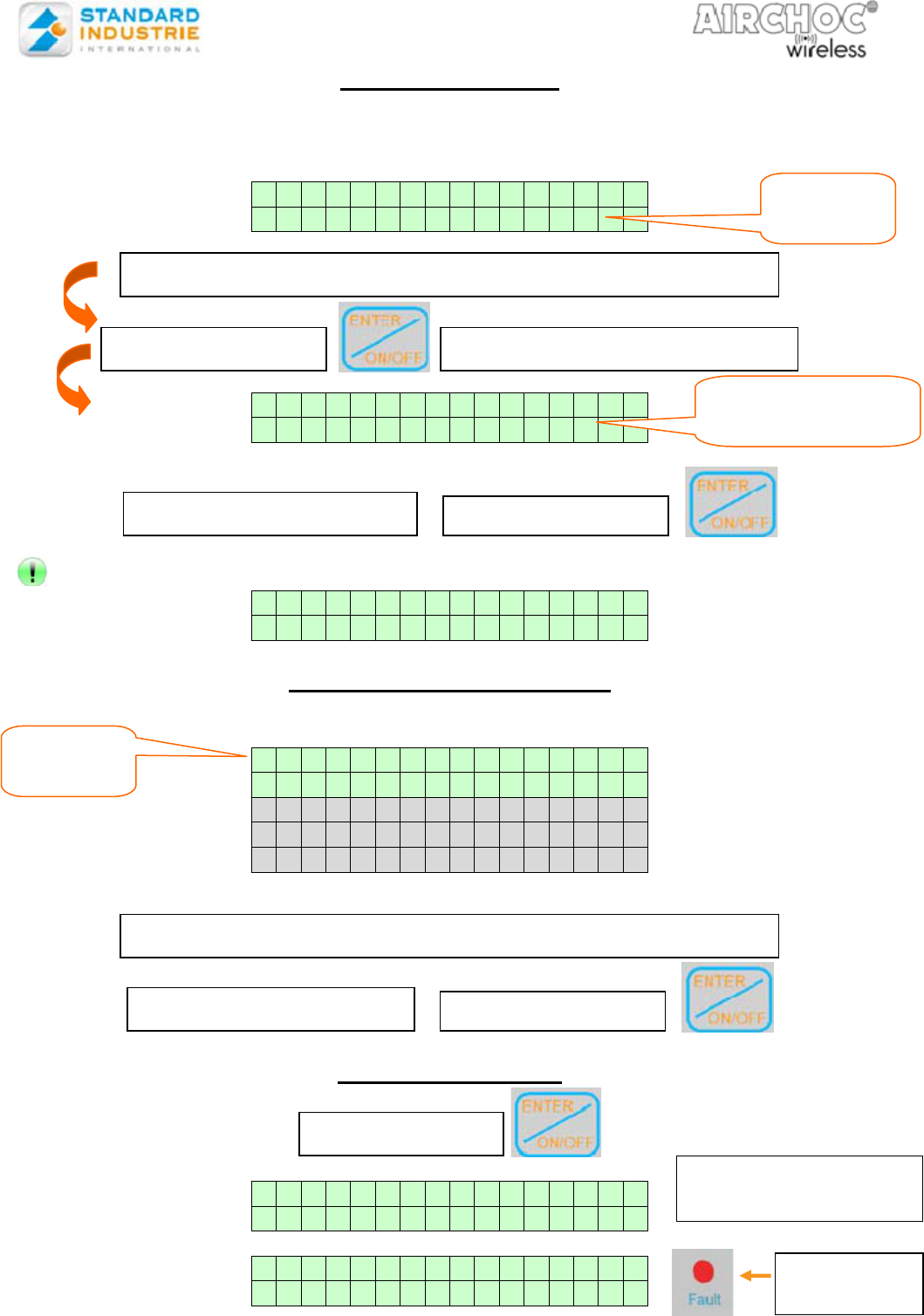
9- Airchoc Consultation
MENU ACCESSED WITHOUT AN ACCESS CODE
This menu is used to check Airchoc faults.
- - > 0 0 1 X X X X
0 0 2 X X X X
X X X X : A c t i v e
O K
f a u l t C o m m N b : 0 1
f a u l t B a t t
f a u l t S o l e n o i d
If a fault is present the red LED is lit.
Warning, if the faults are not acknowledged on the cabinet, every time you view
the selected Airchoc you will see the fault and the fault indicator will be lit.
10- Airchoc Isolation
Menu accessed by access code
After entering the password, the remote control unit connects to the cabinet (to view the
accessible Airchocs).
CONNECTION ESTABLISHED WITH THE CABINET
A C 0 1 : A c t i v e
A C 0 2 : I n a c t i v e
A C 0 1 - > I n a c t i v e
Q u i t V a l i d
A C 0 1 - > I n a c t i v e
Q u i t V a l i d
A C 0 1 : I n a c t i v e
A C 0 2 : I n a c t i v e
Perform the same steps to make the Airchoc Active again and vice-versa.
PRESS
PRESS
PRESS
PRESS ▼
The AIRCHOC
flashes Touch ▲ ▼
to change the Airchoc
Select the
Airchoc to view
with ▲ ▼
Quit flashes
Touch ▲ ▼ to
select
Valid flashes
STATUS OF VARIOUS
AIRCHOCS
To make AC01
Inactive
AC01 flashes AIRCHOC AC01 has
been made inactive
Arrow
flashes
DISPLAY
If there are
faults, the
following is
NOTTELACW-US.doc 9 December 6th, 2012
11- Access code
MENU ACCESSED BY ACCESS CODE, CODE 0000 BY DEFAULT AT DELIVERY
Save a new digital access code:
A c c e s s c o d e :
N e w : 0 0 0 0
A c c e s s c o d e :
N e w : 6430
To access the menu, if the wrong code is entered, the following is displayed:
W r o n g c o d e
12 – Language selection
MENU ACCESSED WITHOUT AN ACCESS CODE
- - > F r a n c a i s
E n g l i s h
E s p a n o l
D e u t s c h
I t a l i a n o
13 – Signal Level
S i g n a l l e v e l
6 4 % O K
S i g n a l l e v e l
1 6 % N o O K
This menu is used to check the communication level where you are located with the remote
control unit and the antenna module or router.
PRESS
PRESS
VALIDATE THE CODE
PRESS
TO GO TO THE NEXT No.
PRESS ▼ o
r
▲ to chan
g
e the values
PRESS
VALIDATE THE CODE
PRESS ▲ or ▼ to select the language
0000
flashes
The last digit
selected flashes
Arrow
flashes
The red
LED comes
AIRCHOC AC01 has
been made inactive
NOTTELACW-US.doc 10 December 6th, 2012
14 – General Information
14-1. Instructions
Changes or modifications not expressly approved by Standard Industrie could void the user's
authority to operate the equipment.
This equipment has been tested and found to comply with the limits for a Class B digital
device, pursuant to part 15 of the FCC Rules. These limits are designed to provide
reasonable protection against harmful interference in a residential installation. This
equipment generates, uses and can radiate radio frequency energy and, if not installed and
used in accordance with the instructions, may cause harmful interference to radio
communications. However, there is no guarantee that interference will not occur in a
particular installation. If this equipment does cause harmful interference to radio or television
reception, which can be determined by turning the equipment off and on, the user is
encouraged to try to correct the interference by one or more of the following measures:
—Reorient or relocate the receiving antenna.
—Increase the separation between the equipment and receiver.
—Connect the equipment into an outlet on a circuit different from that to which the receiver is
connected.
—Consult the dealer or an experienced radio/TV technician for help.
This equipment complies with FCC’s radiation exposure limits set forth for an uncontrolled
environment under the following conditions :
1. This equipment should be installed and operated such that a minimum separation distance
of 20cm is maintained between the radiator (antenna) and user’s/nearby person’s body at
all times.
2. This transmitter must not be co-located or operating in conjunction with any other antenna
or transmitter.
14-2. Remote Control Unit Auto Shut-off
This remote control unit automatically shuts-off after 5 minutes of inactivity. This is indicated
by the green system LED flashing 30 s before shut-off; simply press any key to keep it on.
14-3. Additional Information
It is not possible to use more than one active remote control unit at a time. If this occurs, the
remote control units will be inoperative.
14-4. Using the Battery
Use only 9V 6LF22 or 6LR61 batteries.
Attention, use only alkaline in remote control.
Ensure that the battery is installed in the correct direction on the connector.
Do not dispose of the battery in fire because it may explode.
14-5. Battery and Remote Control Unit Recycling
At the end of the battery or remote control unit service life, you must not dispose of
these products with ordinary household waste. They must be disposed of at an
electrical and electronic device recycling point. Comply with applicable regulations in
your country
14-6. Hazard Area
Certain areas in an industrial environment present potentially explosive atmospheres, it is
recommended that the remote control unit be turned off.

NOTTELACW-US.doc 11 December 6th, 2012
14-7. Warranty
The warranty does not cover damage caused by external factors such as lightning, water,
and fire.
No warranty shall apply if the device was repaired or modified by the purchaser or if its serial
number has been modified, removed, or rendered illegible.
Comply with the instructions for use contained in the manual.
14-8. After Sales Service
Should the remote control unit fail, contact Standard Industrie on + 33-(0)3-20-28-32-32.